MODEL UP-600/700 Dealer Knowledge Book - MS Cash Drawer
MODEL UP-600/700 Dealer Knowledge Book - MS Cash Drawer
MODEL UP-600/700 Dealer Knowledge Book - MS Cash Drawer

You also want an ePaper? Increase the reach of your titles
YUMPU automatically turns print PDFs into web optimized ePapers that Google loves.
SECTION 1. System Presets<br />
Overview…………………………………..…………<br />
Prior to Beginning.……………………..………..….<br />
System Preset Job No.……………..………………<br />
SECTION 2. Free Key Layouts<br />
Overview...…………………………………..………<br />
Free Key Layout Readings..……………………….<br />
Free Key Layout Set Up……………………………<br />
SECTION 3. File Allocation<br />
Overview……………………………………………..<br />
Allocating Memory Files........................................<br />
More on Memory Allocation………………………..<br />
SECTION 4. Peripherals<br />
Overview………………..………….………………..<br />
Peripheral Device Overview..……………….……..<br />
Printers……………………………..………………..<br />
Scanner (Barcode Reader)...………………………<br />
Coin Dispenser……………………………………...<br />
Scale………………………..……...………………...<br />
MCR Unit…………………….…………………..…..<br />
SECTION 5. Inline Setting<br />
Overview……………………………………..………<br />
Inline System Reading………………………..……<br />
Basic Inline System Set Up………………..………<br />
IRC Related Programming……………………..….<br />
Remote Printing and Printer Re-routing……….…<br />
Inline Download Jobs……………………………....<br />
Manual Clear Jobs……………………………..…...<br />
System Backup Master………………………..…...<br />
Inline System Report List…………………………..<br />
Error Handling……………………………………....<br />
SECTION 6. Communication<br />
Overview………………………………….………….<br />
Online via RS-232…………………………………..<br />
RS232 Communications Set Up…………………..<br />
MWS Set Up…………………………………………<br />
MWS Connection……………………………………<br />
MWS Communication Set Up…………………..…<br />
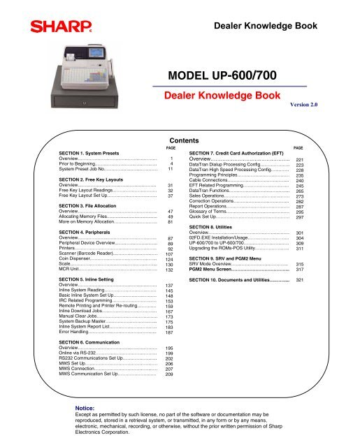
<strong>Dealer</strong> <strong>Knowledge</strong> <strong>Book</strong><br />
<strong>MODEL</strong> <strong>UP</strong>-<strong>600</strong>/<strong>700</strong><br />
<strong>Dealer</strong> <strong>Knowledge</strong> <strong>Book</strong> Version 2.0<br />
Contents<br />
PAGE PAGE<br />
1<br />
4<br />
11<br />
31<br />
32<br />
37<br />
47<br />
49<br />
81<br />
87<br />
89<br />
92<br />
107<br />
124<br />
130<br />
132<br />
137<br />
145<br />
148<br />
153<br />
159<br />
167<br />
173<br />
175<br />
183<br />
187<br />
195<br />
199<br />
202<br />
206<br />
207<br />
209<br />
SECTION 7. Credit Card Authorization (EFT)<br />
Overview………………………………………..<br />
DataTran Dialup Processing Config………………..<br />
DataTran High Speed Processing Config…………<br />
Programming Principles……………..………………<br />
Cable Connections…………………………………..<br />
EFT Related Programming………………………....<br />
DataTran Functions……………………….………....<br />
Sales Operations………………………………..……<br />
Correction Operations……………………………….<br />
Report Operations……………………………………<br />
Glossary of Terms……………………………………<br />
Quick Set Up………………………………………….<br />
SECTION 8. Utilities<br />
Overview……………...………………………...…….<br />
02FD.EXE Installation/Usage……..………………..<br />
<strong>UP</strong>-<strong>600</strong>/<strong>700</strong> to <strong>UP</strong>-<strong>600</strong>/<strong>700</strong>…………………………<br />
Upgrading the ROMs-POS Utility…………………..<br />
SECTION 9. SRV and PGM2 Menu<br />
SRV Mode Overview………………………………..<br />
PGM2 Menu Screen………………………………...<br />
SECTION 10. Documents and Utilities….……....<br />
Notice:<br />
Except as permitted by such license, no part of the software or documentation may be<br />
reproduced, stored in a retrieval system, or transmitted, in any form or by any means,<br />
electronic, mechanical, recording, or otherwise, without the prior written permission of Sharp<br />
Electronics Corporation.<br />
221<br />
223<br />
228<br />
235<br />
240<br />
245<br />
265<br />
273<br />
282<br />
287<br />
295<br />
297<br />
301<br />
304<br />
309<br />
311<br />
315<br />
317<br />
321
TRADEMARKS<br />
<strong>UP</strong>-<strong>600</strong>/<strong>700</strong> <strong>Dealer</strong> <strong>Knowledge</strong> <strong>Book</strong><br />
Sharp, <strong>UP</strong>-<strong>600</strong>, <strong>UP</strong>-<strong>700</strong> and SDW are trademarks of Sharp Electronics<br />
Corporation. Microsoft®, Windows®, Windows 2000 Professional, Windows XP<br />
Professional, and Win32 are trademarks on Microsoft Corporation. Pentium is a<br />
registered trademark of Intel Corporation. AMD and Athlon are trademarks of<br />
Advanced Micro Devices, Inc. 3Com US Robotics® are registered trade marks of<br />
3Com Corporation. All other trademarks and registered trademarks are the<br />
property of their respective holders.<br />
DISCLAIMER<br />
The information contained in this document is furnished without assurance of<br />
peripheral/software compatibility between Sharp POS products and the products<br />
of the suppliers listed.<br />
Product specifications change without notification (both Sharp’ and other<br />
supplier’s products).<br />
Sharp POS does not undertake to update materials. It is the dealer’s<br />
responsibility to keep current with all technical issues associated with these<br />
products.<br />
This Document contains or refers to proprietary information, which is protected<br />
by copyright. All rights are reserved. Copying or other reproduction of this<br />
document is prohibited without written permission of Sharp Corporation.<br />
NOTICE TO USERS<br />
This manual is intended to assist authorized Sharp dealers, with learning and<br />
understanding how to the install the <strong>UP</strong>-<strong>600</strong>/<strong>700</strong>. This documentation assumes<br />
that you are familiar with the general programming concepts of SHARP<br />
POS/ECR systems. Please read each section carefully as it will provide helpful<br />
hints and recommendations that will make your time more efficient and produce<br />
time saving results. This manual is not intended for end user customers of<br />
authorized Sharp dealers.
Section – 1: SYSTEM PRESETS<br />
-
Section-1: Overview<br />
SYSTEM PRESETS<br />
SRV-mode programming consists of service programming jobs, which define the <strong>UP</strong>-<br />
<strong>600</strong>/<strong>700</strong> system capabilities. The service program settings may be printed on the<br />
RECEIPT/JOURNAL printer or displayed on the operator display.<br />
1. SRV-mode Program Main Menu:<br />
SRV-mode Program Main Menu:<br />
Main Menu Description<br />
1 READING<br />
2 SETTING<br />
3 IRC SETTING<br />
4 DOWN LOAD<br />
5 DIAGNOSTIC<br />
Print or view system preset, device configuration, free key, file, and SSP<br />
settings.<br />
Program device configuration, system preset, Z counter, GT, mode secret #,<br />
free key, file, supervisor, memory initial, SSP settings or perform backup send<br />
and backup receive operations.<br />
Program satellite, master, and backup master, standalone with IRC and stand<br />
alone terminal settings or perform an IRC reset.<br />
In an IRC system, transfer SRV parameters (system presets) and free key<br />
program settings from a master terminal to all or an individual satellite terminal<br />
on the existing IRC network.<br />
Perform product&test, ram&rom&ssp, lock&key&switch, serial I/O,<br />
display&printer, mcr&drawer, TCP/IP diagnostic testing. Please refer to the<br />
Service Manual for requirements and possible results.<br />
For more information on SRV Mode programming please see the Service Programming<br />
Manual.<br />
Specifications subject to change without notice: Revision date 10/07 Page 1
<strong>UP</strong>-<strong>600</strong>/<strong>700</strong> <strong>Dealer</strong> <strong>Knowledge</strong> <strong>Book</strong><br />
2. Entering the SRV-Mode<br />
To enter SRV-mode programming, you must turn the SRV key counter clock wise to the 6<br />
o’clock position wait five seconds and turn the SRV key to the 7 o’clock position.<br />
Procedure:<br />
Turn the AC Power Switch “OFF”<br />
Set the mode switch to (SRV’) position<br />
Turn on the AC Power Switch “ON”<br />
Turn to the (SRV) position from (SRV’) position<br />
AC<br />
Powe r<br />
Sw i t c h<br />
The SRV-mode Main Menu will appear:<br />
CAUTION:<br />
Never place the Service key to the SRV’ or SRV position while AC power is applied –<br />
severe damage may result to the RAM and program contents.<br />
3. SRV-mode Program Jobs:<br />
Please refer to the charts below for the available programming options:<br />
NOTE: To use the job number you must be at the SRV Main Menu.<br />
SRV-mode Main Menu:<br />
Main Menu Description<br />
1 READING Reading<br />
2 SETTING Setting<br />
3 IRC SETTING IRC Setting<br />
4 DOWNLOAD Download<br />
5 DIAGNOSTIC Device Configuration (Assignment)<br />
SRV-mode READING Jobs:<br />
Job No. Description<br />
900 System Presets<br />
945 Device Configuration<br />
950 Free Key – Function keys<br />
970 File - Memory Allocation<br />
990 SSP - Special Service Patches<br />
Page 2 Specifications subject to change without notice: Revision date 10/07<br />
SRV<br />
SRV ’
SYSTEM PRESETS<br />
NOTE: To use the job number you must be at the SRV Main Menu or PGM2 Main Menu.<br />
SRV-mode SETTING Jobs:<br />
Job No. Description<br />
945 Device Configuration - R/J, Bill(Slip), Report Printer(X,Z),<br />
Validation, KP1-9, CAT1-2, Pin Pad, Scanner, Scale, Coin Disp,<br />
Online (PC), CVM Data I/F, Prepaid Card, ONL Acct Bal<br />
901 - 981 System Preset<br />
930 - 941 Z-Counters - Trans. Z1/Z2, Cons. Tran Z1/Z2, Server Z1/Z2, Hourly<br />
Z1, PLU/<strong>UP</strong>C Z1/Z2, GLU Z1, Trans Z2, Cons. Tran. Z2, Daily Net Z2<br />
Department Z1/Z2<br />
942, 943, 969 GT – positive, negative, training<br />
944 Mode Secret# - OP XZ, X1, Z1, X2, Z2, PGM1 and PGM2<br />
950 Free Key – Function keys<br />
(n/a) Key Initial – returns the keyboard to master reset settings<br />
971 File – memory allocation<br />
985 Supervisor mode On/Off<br />
989 Memory Initial<br />
- returns the all totals and counters to zero<br />
990 Special Service Patch<br />
996 Backup Send<br />
998 Backup Receive<br />
SRV-mode IRC SETTING Jobs:<br />
Job No. Description<br />
920, PGM 3610, 3611, 3616 Terminal Setting<br />
899, PGM 4900 IRC Reset – Available for Master, Back Up<br />
Master, and Satellite terminals only.<br />
SRV-mode DOWN LOAD Jobs: Available for Master Terminals Only<br />
Job No. Description<br />
800 SRV Parameter<br />
850 Free Key<br />
SRV-mode DIAGNOSTIC Menu: See Service Manual for Requirements<br />
Diagnostic Description<br />
PWB diag, SETdiag, EMI test, Temperature Test,<br />
PRODUCT&TEST DIAG Scanner Test<br />
Standand RAM Check, <strong>UP</strong>-S02MB and <strong>UP</strong>-S04MB<br />
RAM&TOM&SSP DIAG Check , Standard and Service ROM Check, SSP<br />
Check<br />
CLOCK&KEY&SWITCH Date & Time, Key Code, Clerk Code, Mode Switch<br />
SERIAL I/O RS232 I/F DIAG Requires loop back connector CH1-CH8 Check<br />
LCD, popup, pole, printer check, printer cg,<br />
DISPLAY&PRINTER<br />
PES&NES sensor and A/D Converter check<br />
MCR&DRAWER<br />
MCR, <strong>Drawer</strong> 1 and 2 check<br />
Self, Loopback (requires loop back connector), MAC<br />
TCP/IP<br />
ADDR&FIRM Read and Write, Data Trans (MA) and<br />
(SA)<br />
Specifications subject to change without notice: Revision date 10/07 Page 3
<strong>UP</strong>-<strong>600</strong>/<strong>700</strong> <strong>Dealer</strong> <strong>Knowledge</strong> <strong>Book</strong><br />
Section-2: Prior to Beginning<br />
Executing a master reset will initialize the <strong>UP</strong>-<strong>600</strong>/<strong>700</strong> POS terminal. The following three<br />
types of Program and Master Reset operations are available.<br />
Type Description<br />
Program Reset Initializes the hardware and resident program without clearing<br />
memory and totalizers<br />
Master Reset-1 Initializes the hardware and clears the entire memory – restoring<br />
factory initial values<br />
Master-Reset-2 Initializes the hardware and clears the entire memory – restoring<br />
factory initial values and enabling free key layout of the <strong>UP</strong>-<strong>600</strong>/<strong>700</strong><br />
“fixed keys”<br />
Master Reset-3 Is the same as a Master Reset-2 and requires the entry of a serial<br />
number – also prohibiting the reset of the GT totalizers<br />
Definition of Reset-switch<br />
ON position : this position places the CKDC at the “reset” state (Reset status)<br />
OFF position : this position places the CKDC to the “active” state (Normal status)<br />
1. Program Reset:<br />
Follow the below procedure when you wish to perform a program-reset (initialization)<br />
Procedure:<br />
• Turn the AC Power Switch “OFF”<br />
• Set the mode switch to (SRV’) position<br />
• Turn on the AC Power Switch “ON”.<br />
• Turn to the (SRV) position from (SRV’) position.<br />
AC<br />
Powe r<br />
Sw i t c h<br />
The SRV-mode Main Menu will appear:<br />
CAUTION:<br />
Never place the Service key to the SRV’ or SRV position while AC power is applied –<br />
severe damage may result to the RAM and program contents.<br />
Note: When disassembling and reassembling always power up using method 1 only.<br />
Method 2 will not reset the CKDC9.<br />
Note: SRV programming job#926-B must be set to “4” to allow the PGM program loop reset.<br />
Page 4 Specifications subject to change without notice: Revision date 10/07<br />
SRV<br />
SRV ’
2. Master Resets:<br />
Follow one the below procedures when you wish to perform a Master Reset<br />
Master Reset-1 Procedure:<br />
Turn the AC Power Switch “OFF”<br />
Set the MODE switch to the (SRV’) position.<br />
Turn on the AC switch “ON”.<br />
While holding down the JOURNAL FEED key,<br />
turn to the (SRV) position from the (SRV’) position.<br />
Display<br />
AC<br />
Powe r<br />
Sw i t c h<br />
*****MRS.*****<br />
SYSTEM PRESETS<br />
The Master Reset Operation will begin and is finalized upon ‘’3’’ audible beeps.<br />
The SRV-mode Main Menu will appear:<br />
Master Reset-2 Procedure:<br />
Turn the AC Power Switch “OFF”<br />
Set the MODE switch to the (SRV’) position.<br />
Turn on the AC switch “ON”.<br />
While holding down the JOURNAL FEED key, and RECEIPT FEED keys, turn to the<br />
(SRV) position from the (SRV’) position.<br />
AC<br />
Powe r<br />
Sw i t c h<br />
CAUTION:<br />
Never place the Service key to the SRV’ or SRV position while AC power is applied –<br />
severe damage may result to the RAM and program contents.<br />
Specifications subject to change without notice: Revision date 10/07 Page 5<br />
SRV<br />
SRV ’<br />
SRV<br />
SRV ’
<strong>UP</strong>-<strong>600</strong>/<strong>700</strong> <strong>Dealer</strong> <strong>Knowledge</strong> <strong>Book</strong><br />
Key position assignment.<br />
Enter the keys on the key board [0]- [9], [00], [.] [CL], [@/FOR], [SBTL], [<strong>UP</strong>], [DOWN],<br />
[LEFT], [RIGHT], [CANCEL] [ENTER], [CA/AT].<br />
When the 0 key is pressed, the key of the key number displayed is disabled.<br />
Push the key on the keyboard to be assigned. With this, the function key of the key<br />
number displayed is assigned to that key position.<br />
When relocating the keyboard, the PGM 1/2 mode uses the standard key layout.<br />
Turn on the AC switch “ON”.<br />
DISPLAY<br />
Key<br />
No.<br />
Key<br />
Name<br />
Key No.<br />
Key Name Key<br />
No.<br />
Key Name<br />
001 “0” 11 “00” Key 021 “ENTER” key<br />
002 “1” 12 Decimal Point “.” Key 022 “CA/AT” key<br />
003 “2” 13 “CL” Key<br />
004 “3” 14 “(@/FOR)” key<br />
005 “4” 15 “SBTL” key<br />
006 “5” 16 <strong>UP</strong> “”<br />
007 “6” 17 DOWN “”<br />
008 “7” 18 LEFT “<br />
009 “8” 19 RIGHT “”<br />
010 “9” 20 “CANCEL “ key<br />
*****MRS.*****<br />
The Master Reset Operation will begin and is finalized upon ‘’3’’ audible beeps.<br />
Note: After the execution of the MRS-2, only the RECEIPT FEED and JOURNAL<br />
FEED keys remain effective on the key assignment. Any key can be<br />
assigned to any key position on the main keyboard.<br />
CAUTION:<br />
Never place the Service key to the SRV’ or SRV position while AC power is applied –<br />
severe damage may result to the RAM and program contents.<br />
Page 6 Specifications subject to change without notice: Revision date 10/07
SYSTEM PRESETS<br />
Master Reset-3 Procedure:<br />
Turn the AC Power Switch “OFF”<br />
Set the MODE switch to the (SRV’) position.<br />
Turn on the AC switch “ON”.<br />
While holding down the JOURNAL FEED key, and the MRS-3 key, turn to the (SRV)<br />
position from the (SRV’) position.<br />
MRS-3 key : <strong>UP</strong><strong>600</strong>=[CANCEL] key<br />
MRS-3 key : <strong>UP</strong><strong>700</strong>=[PLU72]key<br />
The product serial No. input window is displayed as shown below<br />
Display:<br />
AC<br />
Powe r<br />
Sw i t c h<br />
Enter the product serial number of this POS and depress the [CA/AT] key.<br />
Specifications subject to change without notice: Revision date 10/07 Page 7<br />
SRV<br />
SERIAL No. 00000000<br />
SRV ’
<strong>UP</strong>-<strong>600</strong>/<strong>700</strong> <strong>Dealer</strong> <strong>Knowledge</strong> <strong>Book</strong><br />
Key position assignment.<br />
Enter the keys on the key board [0]- [9], [00], [.] [CL], [@/FOR], [SBTL], [<strong>UP</strong>], [DOWN],<br />
[LEFT], [RIGHT], [CANCEL] [ENTER], [CA/AT].<br />
Key<br />
No.<br />
Key<br />
Name<br />
Key No.<br />
Key Name Key<br />
No.<br />
Key Name<br />
001 “0” 11 “00” Key 021 “ENTER” key<br />
002 “1” 12 Decimal Point “.” Key 022 “CA/AT” key<br />
003 “2” 13 “CL” Key<br />
004 “3” 14 “(@/FOR)” key<br />
005 “4” 15 “SBTL” key<br />
006 “5” 16 <strong>UP</strong> “”<br />
007 “6” 17 DOWN “”<br />
008 “7” 18 LEFT “<br />
009 “8” 19 RIGHT “”<br />
010 “9” 20 “CANCEL “ key<br />
When the 0 key is pressed, the key of the key number displayed is disabled.<br />
Push the key on the keyboard to be assigned. With this, the function key of the<br />
key number displayed is assigned to that key position.<br />
When relocating the keyboard, the PGM1 or PGM2 mode uses the standard key<br />
layout.<br />
Turn on the AC switch “ON”.<br />
Display<br />
*****MRS.*****<br />
The Master Reset Operation will begin and is finalized upon ‘’3’’ audible beeps.<br />
Note: After the execution of the MRS-3, only the RECEIPT FEED and JOURNAL<br />
FEED keys remain effective on the key assignment. Any key can be assigned to<br />
any key position<br />
Page 8 Specifications subject to change without notice: Revision date 10/07
SYSTEM PRESETS<br />
Note: If you perform a Master Reset-3 and then wish to perform a Master Reset-1 or<br />
Master Reset-2, you must disconnect the batteries.<br />
Turn the AC Power Switch “OFF”.<br />
Remove the top cabinet. Please refer to the Installation Manual.<br />
Disconnect the battery from the main board.<br />
Leave the POS unplugged for 24 hours.<br />
Turn on the AC switch “ON”.<br />
You should get a “Ram” error. If not repeat steps 1-4.<br />
Perform the Master Reset-1 or Master Reset-2.<br />
Turn the AC Power Switch “OFF”.<br />
Reconnect the battery to the main board.<br />
CAUTION: Never place the Service key to the SRV’ or SRV position while AC power is<br />
applied – severe damage may result to the RAM and program contents.<br />
Specifications subject to change without notice: Revision date 10/07 Page 9
<strong>UP</strong>-<strong>600</strong>/<strong>700</strong> <strong>Dealer</strong> <strong>Knowledge</strong> <strong>Book</strong><br />
3. System Preset:<br />
When making entries for system presets, leading zeros are not required. Please note that<br />
trailing zeros are required and that the order of entry is from the left-most digit (A) to the<br />
right-most digit (D).<br />
Reference:<br />
1 2 3<br />
SRV MODE<br />
1 READING<br />
2 SETTING<br />
3 IRC SETTING<br />
4 DOWN LOAD<br />
5 DIAGNOSTIC<br />
SETTING <br />
1 DEVICE CONFIG<br />
2 SYSTEM PRESET<br />
3 Z REPORT COUNTER<br />
4 GT<br />
5 MODE SECRET#<br />
6 FREE KEY LAYOUT<br />
SYSTEM PRESET <br />
SRV#901<br />
SRV#902<br />
SRV#903<br />
SRV#904<br />
SRV#905<br />
SRV#906<br />
Page 10 Specifications subject to change without notice: Revision date 10/07<br />
ABCD<br />
0002<br />
0000<br />
8003<br />
0000<br />
0005<br />
0031
Section-3: System Preset Job No.<br />
System Preset: 901<br />
SYSTEM PRESETS<br />
Bit Description Data MRS<br />
---- ---<br />
A ----<br />
----<br />
---<br />
---<br />
0<br />
Enter SUM of Selection ----^<br />
B<br />
Tax System:<br />
Auto Tax 1-4 & Manual Tax System / Canadian Tax (Type 1-10) / Canadian<br />
Tax (Type-11: VAT-on-VAT)<br />
Enter SUM of Selection ----^<br />
0/6/7<br />
0<br />
C<br />
Tax Rounding System:<br />
- Singapore / Normal<br />
Enter SUM of Selection ----^<br />
8/0<br />
0<br />
D<br />
Tab Setting:<br />
- Decimal setting for display and print<br />
Enter SUM of Selection ----^<br />
3/2/1/0<br />
2<br />
NOTE:<br />
-901-C: The Singapore Tax Rounding method will round the tax to the nearest nickel.<br />
System Preset: 902<br />
Bit Description Data MRS<br />
---- ---<br />
A ----<br />
Inline operations are Enabled Yes/No<br />
Enter SUM of Selection ----^<br />
---<br />
1/0<br />
0<br />
---- ---<br />
B ----<br />
----Not Used – Do not change! Fixed at “0”<br />
Enter SUM of Selection ----^<br />
---<br />
---<br />
0<br />
C<br />
Operator Display Format<br />
----<br />
Check Out (2-Line)/GLU Mode -Hospitality<br />
(1-Line)<br />
Enter SUM of Selection ----^<br />
5/0<br />
---<br />
---<br />
<strong>UP</strong>-<strong>600</strong><br />
(5)<br />
<strong>UP</strong>-<strong>700</strong><br />
(0)<br />
---- ---<br />
D ----<br />
----Not Used – Do not change fixed at “0”<br />
---<br />
---<br />
0<br />
Enter SUM of Selection ----^<br />
NOTE:<br />
-902-A: is set automatically during the IRC Setting Terminal selection<br />
-902-C=0: Will display open GLU upon sign-on, if using GLU or GLU recall to display<br />
manually.<br />
-902-C must be set to 5 for scale interface.<br />
Specifications subject to change without notice: Revision date 10/07 Page 11
<strong>UP</strong>-<strong>600</strong>/<strong>700</strong> <strong>Dealer</strong> <strong>Knowledge</strong> <strong>Book</strong><br />
System Preset: 903<br />
Bit Description Data MRS<br />
A<br />
All RAM data Send/Receive Baud Rate (bps):<br />
115200/57<strong>600</strong>/38400/19200/9<strong>600</strong>/4800/2400<br />
8/7/6/5<br />
/4/3/2<br />
Enter SUM of Selection ----^<br />
---- ---<br />
B Measure of Weight for Scale Entries<br />
----<br />
Kg/Lb<br />
Enter SUM of Selection ----^<br />
2/0<br />
---<br />
0<br />
---- ---<br />
Tare Weight Entry is disallowed / Scale Weight System 2 decimal places 0<br />
C Tare Weight Entry is disallowed / Scale Weight System 3 decimal places<br />
Tare Weight Entry is allowed / Scale Weight System 2 decimal places<br />
1<br />
2<br />
0<br />
Tare Weight Entry is allowed / Scale Weight System 3 decimal places<br />
Enter SUM of Selection ----^<br />
3<br />
Tax is not charged on Food Stamp<br />
items<br />
3<br />
D Food Stamp System:<br />
Tax is payable w/ Food Stamps 2<br />
Tax is NOT payable w/ Food Stamps 1<br />
No Food Stamps<br />
Enter SUM of Selection ----^<br />
0<br />
NOTE:<br />
-903-A is applicable for the 02FD.exe utility (not Online communications) and ECR to ECR<br />
Data Transfer.<br />
-903C = 0 for CAS Scale<br />
System Preset: 904<br />
Page 12 Specifications subject to change without notice: Revision date 10/07<br />
8<br />
<strong>UP</strong>-<strong>600</strong><br />
(3)<br />
<strong>UP</strong>-<strong>700</strong><br />
(0)<br />
Bit Description Data MRS<br />
Date is printed No/Yes 4/0<br />
A Gas Department Fraction Calculation<br />
----<br />
Ignore/Round Up/Round Off<br />
Enter SUM of Selection ----^<br />
2/1/0<br />
---<br />
0<br />
Consecutive No. is printed No/Yes 4/0<br />
B Gas Dept. Decimal Position<br />
----<br />
Enter SUM of Selection ----^<br />
3/2/1/0<br />
---<br />
0<br />
---- ---<br />
C Gas Dept. Discount Fraction Calculation<br />
----<br />
Ignore/Round Up/Round Off<br />
Enter SUM of Selection ----^<br />
2/1/0<br />
---<br />
0<br />
---- ---<br />
D Gas Dept. Unit Price Tab Position<br />
Gas Dept. Function is Enabled<br />
3 decimal palces/2 decimal places<br />
Yes/No<br />
Enter SUM of Selection ----^<br />
2/0<br />
1/0<br />
0<br />
NOTE:
-904-A&B applies to Receipts, Guest Checks, and Kitchen Print chits<br />
System Preset: 905<br />
SYSTEM PRESETS<br />
Bit Description Data MRS<br />
Tax4 Subtotal is printed on Trans. Reports No/Yes 4/0<br />
A Gross Tax4 & Refund Tax4 Totals are printed on Trans. Reports<br />
Net Tax4 Total is printed on Trans. Reports<br />
No/Yes<br />
No/Yes<br />
2/0<br />
1/0<br />
0<br />
Enter SUM of Selection ----^<br />
Tax is printed when the Taxable Subtotal = $0.00 Yes/No 4/0<br />
B Tax is printed when GST is VAT<br />
Tax is printed when Tax = $0.00<br />
No/Yes<br />
No/Yes<br />
2/0<br />
1/0<br />
0<br />
GST Exempt is printed on Trans. Reports<br />
Enter SUM of Selection ----^<br />
No/Yes 4/0<br />
C<br />
----<br />
----<br />
Enter SUM of Selection ----^<br />
---<br />
----<br />
0<br />
D<br />
Canadian Tax System:<br />
Type10/Type9/Type8/Type7/Type6/Type5/Type4/Type3/Type2/Type1<br />
Enter SUM of Selection ----^<br />
9/8/7/6<br />
/5/4/3/<br />
2/1/0<br />
5<br />
NOTE:<br />
-Trans. Report represents both X1/Z1 and X2/Z2<br />
System Preset: 906<br />
Bit Description Data MRS<br />
Dept. & PLU/<strong>UP</strong>C Codes are printed Yes/No 4/0<br />
A PLU/<strong>UP</strong>C Stock System:<br />
Entry is Inhibited/Error Message and Operation continues/Allowed<br />
Enter SUM of Selection ----^<br />
2/1/0 0<br />
Bottle Return Function is Enabled Yes/No 4/0<br />
B Hash Dept. is Enabled<br />
----<br />
Yes/No<br />
Enter SUM of Selection ----^<br />
2/0<br />
---<br />
0<br />
C<br />
Multiplication System:<br />
Fast Food (FF sequence)/Split-Price/Successive Multiplication/Multiplication<br />
Enter SUM of Selection ----^<br />
3/2/1/0 3<br />
PLU/<strong>UP</strong>C Price Look Up at Refund Entry No/Yes 4/0<br />
D Presetting of the Consecutive No. is Enabled<br />
Fractional Qty System is enabled (3 decimal places)<br />
No/Yes<br />
Yes/No<br />
2/0<br />
1/0<br />
0<br />
Enter SUM of Selection ----^<br />
NOTE:<br />
-To enable Scale entries 906-D must be set = 1, 3, 5 or 7<br />
-To allow OPEN type PLU entries 906-C FF(Fast Food Sequence) must be disabled.<br />
-FF(Fast Food Sequence) cannot be used for Coupon Like PLU.<br />
Specifications subject to change without notice: Revision date 10/07 Page 13
<strong>UP</strong>-<strong>600</strong>/<strong>700</strong> <strong>Dealer</strong> <strong>Knowledge</strong> <strong>Book</strong><br />
System Preset: 907<br />
Bit Description Data MRS<br />
---- ---<br />
A ----<br />
----<br />
---<br />
---<br />
0<br />
Enter SUM of Selection ----^<br />
---- ---<br />
B <strong>UP</strong>C code is printed on the Journal<br />
<strong>UP</strong>C code is printed on the Receipt<br />
No/Yes<br />
No/Yes<br />
Enter SUM of Selection ----^<br />
2/0<br />
1/0<br />
0<br />
---- ---<br />
C ----<br />
Minus Dept. and PLU items are Enabled Yes/No<br />
Enter SUM of Selection ----^<br />
---<br />
1/0<br />
1<br />
---- ---<br />
D ----<br />
----<br />
Enter SUM of Selection ----^<br />
---<br />
---<br />
0<br />
NOTE:<br />
- To enable Coupon PLU items 907-C must be set = 1<br />
System Preset: 908<br />
Bit Description Data MRS<br />
GT1 is printed on the Trans.-Z Report No/Yes 4/0<br />
A GT2 is printed on the Trans.-Z Report<br />
GT3 is printed on the Trans.-Z Report<br />
No/Yes<br />
No/Yes<br />
Enter SUM of Selection ----^<br />
2/0<br />
1/0<br />
0<br />
GT1 is printed on the Trans.-X Report Yes/No 4/0<br />
B GT2 is printed on the Trans.-X Report<br />
GT3 is printed on the Trans.-X Report<br />
Yes/No<br />
Yes/No<br />
Enter SUM of Selection ----^<br />
2/0<br />
1/0<br />
0<br />
VOID-mode operations affect the Hourly Report Yes/No 4/0<br />
C ----<br />
Consecutive No. is Reset upon a Trans.-Z Report Yes/No<br />
---<br />
1/0<br />
0<br />
X/Z Report Printing:<br />
Enter SUM of Selection ----^<br />
Journal only/Receipt & Journal 4/0<br />
D ----<br />
Trans.-Z1 Report resets the GT Yes/No<br />
Enter SUM of Selection ----^<br />
---<br />
1/0<br />
0<br />
NOTE:<br />
- 908-D: The X/Z Report printing option does not apply to Individual Server Report<br />
Trans- Z1 GT reset option is not allowed if a Master Reset 3 was executed.<br />
Page 14 Specifications subject to change without notice: Revision date 10/07
System Preset: 909<br />
SYSTEM PRESETS<br />
Bit Description Data MRS<br />
---- ---<br />
A Training GT is printed on the Trans.-X Report<br />
Training GT is printed on the Trans.-Z Report<br />
Yes/No<br />
No/Yes<br />
Enter SUM of Selection ----^<br />
2/0<br />
1/0<br />
2<br />
PLU/<strong>UP</strong>C Item Data is printed on the Z Report No/Yes 4/0<br />
B ----<br />
----<br />
---<br />
---<br />
0<br />
Enter SUM of Selection ----^<br />
VOID-mode & MGR VOID is printed on the Trans.-Z2 Report No/Yes 4/0<br />
C VOID-mode & MGR VOID is printed on the Trans.-Z1 Report<br />
----<br />
No/Yes 2/0<br />
---<br />
0<br />
Enter SUM of Selection ----^<br />
---- ---<br />
D ----<br />
----<br />
---<br />
---<br />
0<br />
Enter SUM of Selection ----^<br />
NOTE:<br />
-909-B: No Sales Data is printed for the PLU-Z Report when = 4<br />
System Preset: 910<br />
Bit Description Data MRS<br />
---- ---<br />
A The <strong>Cash</strong> <strong>Drawer</strong> opens at Server Sign-On<br />
----<br />
Yes/No<br />
Enter SUM of Selection ----^<br />
2/0<br />
---<br />
0<br />
---- ---<br />
B ----<br />
----<br />
Enter SUM of Selection ----^<br />
---<br />
---<br />
0<br />
---- ---<br />
C Server/<strong>Cash</strong>ier Sign-on System<br />
----<br />
Auto Sign-Off/Stay-Down<br />
Enter SUM of Selection ----^<br />
2/0<br />
---<br />
2<br />
(Fixed): Server/<strong>Cash</strong>ier system is code entry 4<br />
D ----<br />
----<br />
Enter SUM of Selection ----^<br />
---<br />
---<br />
4<br />
NOTE:<br />
- 910-A: The <strong>Cash</strong> drawer opening is based on the Individual Server preset<br />
- 910-C: The Server stay-down system requires a manual sign-off sequence<br />
- 910-C = 0: Sign-ON/OFF chit prints.<br />
Specifications subject to change without notice: Revision date 10/07 Page 15
<strong>UP</strong>-<strong>600</strong>/<strong>700</strong> <strong>Dealer</strong> <strong>Knowledge</strong> <strong>Book</strong><br />
System Preset: 911<br />
Bit Description Data MRS<br />
---- ---<br />
A ----<br />
Fractional Qty System: Ignored/Round-Up/Round-Off<br />
Enter SUM of Selection ----^<br />
---<br />
2/1/0<br />
0<br />
<strong>UP</strong>C Check Digit System Checking is Enabled Yes/No 4/0<br />
B ----<br />
----<br />
---<br />
---<br />
0<br />
Enter SUM of Selection ----^<br />
---- ---<br />
C ----<br />
----<br />
---<br />
---<br />
0<br />
Enter SUM of Selection ----^<br />
---- ---<br />
D<br />
----<br />
Receipt/Journal/(Bill)Slip Header<br />
Format:<br />
Format-3/Format-2/Format-1<br />
Enter SUM of Selection ----^<br />
---<br />
4/2/0<br />
0<br />
NOTE:<br />
- 911-A: Must be set for rounding for Scale operations = 0<br />
- 911-B: You cannot modify this setting once <strong>UP</strong>C codes have been preset in the system<br />
- 911-D: Format-1 = Format-2 = Format-3 =<br />
System Preset: 912<br />
Bit Description Data MRS<br />
---- ---<br />
A ----<br />
Date Print Format YYMMDD/DDMMYY/MMDDYY<br />
Enter SUM of Selection ----^<br />
---<br />
2/1/0<br />
0<br />
---- ---<br />
B ----<br />
Time Clock System 24-Hour System/12-Hour System<br />
Enter SUM of Selection ----^<br />
---<br />
1/0<br />
0<br />
Receipt After-Transaction Format Detailed/Totals only 4/0<br />
C Copy Receipt Function is Enabled<br />
Receipt Footer Print Control<br />
Yes/No<br />
By Media Preset/All Receipts<br />
Enter SUM of Selection ----^<br />
2/0<br />
1/0<br />
6<br />
3-Line Header – No Stamp 0<br />
Graphic Logo Stamp only 1<br />
D Logo Message Control: Graphic Logo Stamp & 3-Line Footer<br />
6-Line Header – No Stamp<br />
2<br />
3<br />
1<br />
3-Line Header – No Stamp/3-Line Footer<br />
Enter SUM of Selection ----^<br />
5<br />
NOTE:<br />
Page 16 Specifications subject to change without notice: Revision date 10/07
- 912-D: The STAMP (Graphic Logo) selection is for the <strong>UP</strong>-<strong>700</strong> only<br />
System Preset: 913<br />
SYSTEM PRESETS<br />
Bit Description Data MRS<br />
---- ---<br />
A Validation Print Format<br />
Validation: Amount Contents<br />
Machine No. & Amount/Date & Amount<br />
Tendered Amount/Total Sale Amount<br />
Enter SUM of Selection ----^<br />
2/0<br />
1/0<br />
0<br />
Subtotal is printed when the [SBTL] key is depressed Yes/No 4/0<br />
B Merch. Subtotal is printed when the [MDSE] key is depressed<br />
Escaping Compulsory Bill print is Enabled<br />
Yes/No<br />
Yes/No<br />
2/0<br />
1/0<br />
1<br />
Enter SUM of Selection ----^<br />
---- ---<br />
C Error-Tone System<br />
Keyboard Buffering is Enabled<br />
Until [CL] is depressed/2 seconds<br />
No/Yes<br />
Enter SUM of Selection ----^<br />
2/0<br />
1/0<br />
0<br />
Compulsory <strong>Drawer</strong> Closed prior to operation is enabled Yes/No 4/0<br />
D Error System<br />
Key Touch-Tone is enabled<br />
“Misoperation”/One-Shot Error only<br />
No/Yes<br />
Enter SUM of Selection ----^<br />
2/0<br />
1/0<br />
4<br />
NOTE:<br />
- 913-A: Validation Print format selection is for the <strong>UP</strong>-<strong>600</strong> only. The <strong>UP</strong>-<strong>700</strong> uses the TM-<br />
295 for Validation. The <strong>UP</strong>-<strong>700</strong> internal printer cannot be used for VP.<br />
- 913-B: The sequence for escaping “Compulsory” Bill print operations: [.] [BILL]<br />
System Preset: 914<br />
Bit Description Data MRS<br />
Receipts are printed upon [NO SALE] operations No/Yes 4/0<br />
A The [NO SALE] function is combined with the [CASH] key<br />
Tax Delete function is Enabled<br />
Yes/No<br />
Yes/No<br />
2/0<br />
1/0<br />
1<br />
Enter SUM of Selection ----^<br />
---- ---<br />
B ----<br />
The [NO SALE] function is allowed after a Non-Add No. entry Yes/No<br />
---<br />
1/0<br />
1<br />
Paper Near End Error Sys<br />
Enter SUM of Selection ----^<br />
Enforce Paper Placement/Unlock w/ [CL] key ---<br />
C VOID-mode is Enabled<br />
Non-Add # Entry is Compulsory at the beginning of each Trans.<br />
No/Yes<br />
Yes/No<br />
2/0<br />
1/0<br />
0<br />
Manual Tax entry is Enabled<br />
Enter SUM of Selection ----^<br />
No/Yes 4/0<br />
D Check-<strong>Cash</strong>ing function is Enabled<br />
Non-Add # Entry is Enabled<br />
Yes/No<br />
No/Yes<br />
Enter SUM of Selection ----^<br />
2/0<br />
1/0<br />
0<br />
NOTE:<br />
Specifications subject to change without notice: Revision date 10/07 Page 17
<strong>UP</strong>-<strong>600</strong>/<strong>700</strong> <strong>Dealer</strong> <strong>Knowledge</strong> <strong>Book</strong><br />
System Preset: 915<br />
Bit Description Data MRS<br />
---- ---<br />
A ----<br />
Dollar Amount Symbol (Space), (*) Asterisk, ($) Dollar Symbol<br />
Enter SUM of Selection ----^<br />
---<br />
2/1/0<br />
0<br />
---- ---<br />
B ----<br />
[PO] System <strong>Cash</strong> only/Mixed-Tender<br />
Enter SUM of Selection ----^<br />
---<br />
1/0<br />
0<br />
Near-End Paper Checking function is Enabled No/Yes 4/0<br />
C SBTL (-) or SBTL (%) within the same Transaction<br />
[RA] System<br />
Once/Any No. Times<br />
<strong>Cash</strong> only/Mixed-Tender<br />
2/0<br />
1/0<br />
4<br />
Enter SUM of Selection ----^<br />
---- ---<br />
D ----<br />
----<br />
---<br />
---<br />
0<br />
Enter SUM of Selection ----^<br />
NOTE:<br />
- 915-C: The Near-End paper sensor is for the <strong>UP</strong>-<strong>600</strong> (DP-750) printer only<br />
System Preset: 916<br />
Bit Description Data MRS<br />
---- ---<br />
A ----<br />
Print when the No. Text Characters overlap the Amount 2-Line/Truncate<br />
---<br />
1/0<br />
1<br />
Enter SUM of Selection ----^<br />
Charge Media Finalization when the Amount = $0.00 Yes/No 4/0<br />
B ----<br />
Food Stamp SBTL is Compulsory before FS-Tender Yes/No<br />
---<br />
1/0<br />
4<br />
Allow the MDSE SBTL to go Negative<br />
Enter SUM of Selection ----^<br />
No/Yes 4/0<br />
C [SBTL] Entry is Compulsory before Tendering Finalization<br />
[SBTL] Entry is Compulsory before Direct Finalization<br />
Yes/No<br />
Yes/No<br />
2/0<br />
1/0<br />
0<br />
Enter SUM of Selection ----^<br />
Coupon PLU Totalizer prints on the Trans.-(X/Z) Reports No/Yes 4/0<br />
D NET Sales SBTL (NET1) is printed on the Trans.-(X/Z) Reports<br />
Check change Totalizer is printed on the Trans.-(X/Z) Reports<br />
No/Yes<br />
No/Yes<br />
2/0<br />
1/0<br />
0<br />
Enter SUM of Selection ----^<br />
NOTE:<br />
-916-C: Allow the sales transaction to go negative<br />
Page 18 Specifications subject to change without notice: Revision date 10/07
System Preset: 917<br />
SYSTEM PRESETS<br />
Bit Description Data MRS<br />
Tax1 Subtotal is printed on Trans. Reports No/Yes 4/0<br />
A Gross Tax1 & Refund Tax1 Totals are printed on Trans. Reports<br />
Net Tax1 Total is printed on Trans. Reports<br />
No/Yes<br />
No/Yes<br />
2/0<br />
1/0<br />
0<br />
Tax2 Subtotal is printed on Trans. Reports<br />
Enter SUM of Selection ----^<br />
No/Yes 4/0<br />
B Gross Tax2 & Refund Tax2 Totals are printed on Trans. Reports<br />
Net Tax2 Total is printed on Trans. Reports<br />
No/Yes<br />
No/Yes<br />
2/0<br />
1/0<br />
0<br />
Tax3 Subtotal is printed on Trans. Reports<br />
Enter SUM of Selection ----^<br />
No/Yes 4/0<br />
C Gross Tax3 & Refund Tax3 Totals are printed on Trans. Reports<br />
Net Tax1 Total is printed on Trans. Reports<br />
No/Yes<br />
No/Yes<br />
2/0<br />
1/0<br />
0<br />
Enter SUM of Selection ----^<br />
Total Tax is printed on the Trans.-(X/Z) Reports No/Yes 4/0<br />
D Gross & Ref. Manual Tax Totals are printed on Trans. Reports<br />
Net Manual Tax Totalizer is printed on Trans.-(X/Z) Reports<br />
No/Yes<br />
No/Yes<br />
2/0<br />
1/0<br />
0<br />
Enter SUM of Selection ----^<br />
NOTE:<br />
System Preset: 918<br />
Bit Description Data MRS<br />
Assoc. PLU Text of Combo Meals is printed No/Yes 4/0<br />
Direct-Tender for 2 nd A<br />
or subsequent tender is allowed Yes/No<br />
Combo Meal Kitchen Printer printing is by Combo Meal’s KP/by PLU’s KP<br />
Enter SUM of Selection ----^<br />
2/0<br />
1/0<br />
2<br />
---- ---<br />
B PLU is printed in RED when the unit price is $0.00<br />
Fractional entries allowed for non-Scalable Dept. & PLU items<br />
Yes/No<br />
No/Yes<br />
2/0<br />
1/0<br />
2<br />
Enter SUM of Selection ----^<br />
---- ---<br />
C Kitchen Printer output Groups Like Items<br />
Kitchen Printer output prints Dept. & PLU Text in Double-Sized<br />
No/Yes<br />
Yes/No<br />
2/0<br />
1/0<br />
3<br />
Tip Paid function includes <strong>Cash</strong> Tips<br />
Enter SUM of Selection ----^<br />
No/Yes 4/0<br />
D Tip Totals are Reset upon executing a Server Z1 Report<br />
Tip Totalizer is printed on the Server Report<br />
Yes/No<br />
Yes/No<br />
2/0<br />
1/0<br />
3<br />
Enter SUM of Selection ----^<br />
NOTE:<br />
- 918-C: Does not apply to items that are entered as part of a Condiment entry<br />
Specifications subject to change without notice: Revision date 10/07 Page 19
<strong>UP</strong>-<strong>600</strong>/<strong>700</strong> <strong>Dealer</strong> <strong>Knowledge</strong> <strong>Book</strong><br />
System Preset: 919<br />
Bit Description Data MRS<br />
Guest Check System GLU (detail)/PBLU (totals) 4/2<br />
A ----<br />
GLU/PBLU Entry is Compulsory for Reorder Entries No/Yes<br />
---<br />
1/0<br />
5<br />
Enter SUM of Selection ----^<br />
Checking of Server# for Guest Check Entries when re-ordering No/Yes 4/0<br />
B ----<br />
Guest Check Number-System Entry Manual/Auto-Generate<br />
Enter SUM of Selection ----^<br />
---<br />
1/0<br />
1<br />
---- ---<br />
C [GLU/PBLU] Entry is Compulsory<br />
Amount Prints when PLU Unit Price is $0.00 (recei[pt/bill)<br />
Yes/No<br />
Yes/No<br />
2/0<br />
1/0<br />
0<br />
Enter SUM of Selection ----^<br />
Normal SBTL is printed in addition to the Conversion SBTL No/Yes 4/0<br />
D ----<br />
Foreign Currency Format Omit Decimal Digits/Not<br />
Enter SUM of Selection ----^<br />
---<br />
1/0<br />
0<br />
NOTE:<br />
- 919-B: Requires that the Auto GLU Gen (File 40) is allocated.<br />
- 919-C: Text will always print even if Amount prints when PLU Unit Price is $0.00.<br />
System Preset: 920<br />
Bit Description Data MRS<br />
---- ---<br />
A (Fixed)<br />
Back-Up Master Function is Enabled Yes/No<br />
Enter SUM of Selection ----^<br />
2<br />
1/0<br />
2<br />
Back-Up Master can perform System Reports & Download Jobs No/Yes 4/0<br />
B ----<br />
----<br />
---<br />
---<br />
0<br />
Enter SUM of Selection ----^<br />
Inline Download Jobs are Broadcasted (vs. sending individual) No/Yes 4/0<br />
C ----<br />
PGM2-Mode Programming is allowed at the Satellite Terminal Yes/No<br />
---<br />
1/0<br />
4<br />
Enter SUM of Selection ----^<br />
Back-up Master 3<br />
D The POS Terminal Type<br />
Master<br />
Satellite<br />
2<br />
1 0<br />
Standalone<br />
Enter SUM of Selection ----^<br />
0<br />
NOTE:<br />
- 920-D: This is setting is determined in the IRC Setting / Terminal Setting<br />
Programming in the SRV Mode.<br />
Page 20 Specifications subject to change without notice: Revision date 10/07
System Preset: 921<br />
SYSTEM PRESETS<br />
Bit Description Data MRS<br />
Convert <strong>UP</strong>C-E codes to <strong>UP</strong>C-A Yes/No 4/0<br />
A ----<br />
----<br />
2/0<br />
1/0<br />
0<br />
GLU System Control<br />
Enter SUM of Selection ----^<br />
Each Terminal/Centralized (Master) 4/0<br />
B ----<br />
----<br />
---<br />
---<br />
0<br />
Enter SUM of Selection ----^<br />
---- ---<br />
C ----<br />
Bill Printing Method: Item Data Is Retained/Item Data is Cleared<br />
Enter SUM of Selection ----^<br />
---<br />
1/0<br />
0<br />
Individual Server Report executes the Tip Paid function No/Yes 4/0<br />
D ----<br />
----<br />
---<br />
---<br />
0<br />
Enter SUM of Selection ----^<br />
NOTE:<br />
- 921-A: Do not modify this setting once <strong>UP</strong>C codes have been preset<br />
- 921-C For roll/soft check printers only.<br />
System Preset: 922<br />
Bit Description Data MRS<br />
---- ---<br />
A ----<br />
----<br />
---<br />
---<br />
0<br />
Enter SUM of Selection ----^<br />
---- ---<br />
B ----<br />
$1 Coin Dispenser Handling is Enabled Yes/No<br />
Enter SUM of Selection ----^<br />
---<br />
1/0<br />
0<br />
---- ---<br />
C ---- ---<br />
0<br />
Enter SUM of Selection ----^<br />
---- ---<br />
D ---- ---<br />
---- ---<br />
Enter SUM of Selection ----^<br />
NOTE:<br />
Specifications subject to change without notice: Revision date 10/07 Page 21<br />
0
<strong>UP</strong>-<strong>600</strong>/<strong>700</strong> <strong>Dealer</strong> <strong>Knowledge</strong> <strong>Book</strong><br />
System Preset: 923<br />
Bit Description Data MRS<br />
A<br />
B<br />
The No. of Records which are requested for the T-Log Polling Function<br />
(x 100)<br />
example: if AB = 15; then the Satellite will request for T-Log polling when the<br />
no. of records reaches 1500 (15 x 100)<br />
* see Note below when referring to a Master or Standalone terminal<br />
0 - 99<br />
Enter SUM of Selection ----^<br />
---- ---<br />
C ---- ---<br />
T-Log Function is Enabled Yes/No<br />
Enter SUM of Selection ----^<br />
1/0<br />
---- ---<br />
D ---- ---<br />
T-Log Polling Cycle (seconds) 0 - 9<br />
Enter SUM of Selection ----^<br />
NOTE:<br />
- 923-A+B: Satellite Terminals<br />
• (AB setting) x (100) = No. Records stored before the Satellite makes its<br />
request to the Master to poll the T-Log data<br />
Master Terminals<br />
• AB = 00: T-Log Data sending to the MWS PC is disabled<br />
• AB = 01 – 99: (AB setting) x (100) = No. Records stored before the Master<br />
makes its request to the MWS PC to poll T-Log data<br />
- 923-D: This setting is the wait-cycle (in seconds) for the Master when making the next<br />
T-Log polling request<br />
Page 22 Specifications subject to change without notice: Revision date 10/07<br />
00<br />
1<br />
0
System Preset: 924<br />
SYSTEM PRESETS<br />
Bit Description Data MRS<br />
---- ---<br />
A ----<br />
(Fixed)<br />
---<br />
1<br />
1<br />
Enter SUM of Selection ----^<br />
(Fixed) 4<br />
B ----<br />
----<br />
---<br />
---<br />
4<br />
Enter SUM of Selection ----^<br />
---- ---<br />
C (Fixed)<br />
(Fixed)<br />
2<br />
1<br />
3<br />
D<br />
Inline System Control upon Individual<br />
Z2 Resetting Reports<br />
Enter SUM of Selection ----^<br />
Lock After Ind. Daily Net Z2 Report<br />
Lock after Ind. Trans. Z2 Report<br />
Enter SUM of Selection ----^<br />
2/0<br />
1/0 3<br />
NOTE:<br />
System Preset: 925<br />
Bit Description Data MRS<br />
---- ---<br />
A ----<br />
----<br />
---<br />
---<br />
0<br />
Enter SUM of Selection ----^<br />
---- ---<br />
B (Fixed)<br />
Various Individual report jobs are allowed Yes/No<br />
Enter SUM of Selection ----^<br />
2<br />
1/0<br />
3<br />
C Print format for Consol. Reports:<br />
Individual only 2<br />
Consolidated only 1 0<br />
Individual & Consolidated<br />
Enter SUM of Selection ----^<br />
0<br />
---- ---<br />
D Allow resetting reports while Server remains signed-on<br />
Allow resetting reports while the store is open<br />
Yes/No<br />
Yes/No<br />
2/0<br />
1/0<br />
3<br />
Enter SUM of Selection ----^<br />
NOTE:<br />
925-B: When selecting No = “0”, only the Master will be able to reset the reports<br />
Specifications subject to change without notice: Revision date 10/07 Page 23
<strong>UP</strong>-<strong>600</strong>/<strong>700</strong> <strong>Dealer</strong> <strong>Knowledge</strong> <strong>Book</strong><br />
System Preset: 926<br />
Bit Description Data MRS<br />
---- ---<br />
A Direct Voids and the Voided item is printed on the KP<br />
Past Voids and the Voided item is printed on the KP<br />
No/Yes<br />
No/Yes<br />
2/0<br />
1/0<br />
0<br />
Program Reset via PGM2-Mode is Enabled<br />
Enter SUM of Selection ----^<br />
Yes/No 4/0<br />
B Refunded Data is sent to the KP<br />
----<br />
No/Yes<br />
Enter SUM of Selection ----^<br />
2/0<br />
---<br />
0<br />
Open/Close Store operation is Enabled for Standalone w/ Online Yes/No 4/0<br />
C Send AT Command String when Open Store is Executed<br />
Send AT Command String when Close Store is Executed<br />
Yes/No<br />
Yes/No<br />
2/0<br />
1/0<br />
0<br />
Enter SUM of Selection ----^<br />
Online Channel is Reversed in Close Store state Yes/No 4/0<br />
D ----<br />
----<br />
---<br />
---<br />
0<br />
Enter SUM of Selection ----^<br />
NOTE:<br />
System Preset: 927<br />
Bit Description Data MRS<br />
---- ---<br />
A ----<br />
----<br />
---<br />
---<br />
0<br />
Enter SUM of Selection ----^<br />
---- ---<br />
B ----<br />
----<br />
---<br />
---<br />
0<br />
Enter SUM of Selection ----^<br />
---- ---<br />
C ----<br />
----<br />
---<br />
---<br />
0<br />
Enter SUM of Selection ----^<br />
---- ---<br />
D ----<br />
----<br />
---<br />
---<br />
0<br />
Enter SUM of Selection ----^<br />
NOTE:<br />
Page 24 Specifications subject to change without notice: Revision date 10/07
System Preset: 928<br />
SYSTEM PRESETS<br />
Bit Description Data MRS<br />
---- ---<br />
A ----<br />
SLIP Logo Text is Printed Yes/No<br />
Enter SUM of Selection ----^<br />
---<br />
1/0<br />
1<br />
---- ---<br />
B VP Message printing on Slip is Enabled for Check & Charge<br />
Header is Printed on Slip when Reorder entries are printed<br />
Yes/No<br />
No/Yes<br />
2/0<br />
1/0<br />
0<br />
Enter SUM of Selection ----^<br />
PLU is printed on the [BILL] when the unit price = $0.00 No/Yes 4/0<br />
C Combo Meal Individual PLU Item Text is printed on the [BILL]<br />
----<br />
No/Yes 2/0<br />
---<br />
6<br />
Enter SUM of Selection ----^<br />
Compulsory Bill Print System:<br />
D<br />
Compulsory for GLU/PBLU entries<br />
Compulsory for every entry<br />
2<br />
1 0<br />
NOTE:<br />
Compulsory based on Media key preset<br />
Enter SUM of Selection ----^<br />
0<br />
System Preset: 929<br />
Bit Description Data MRS<br />
---- ---<br />
A ----<br />
KP Print format for Media Keys Detailed/Summary<br />
Enter SUM of Selection ----^<br />
---<br />
1/0<br />
0<br />
---- ---<br />
B ----<br />
Server & Trans.-Z Resetting is allowed when Open GLUs exist Yes/No<br />
---<br />
1/0<br />
0<br />
Enter SUM of Selection ----^<br />
---- ---<br />
C ----<br />
Sales entries can continue when the Closed GLU file is FULL Yes/No<br />
---<br />
1/0<br />
0<br />
Tax Print Method and PLU/<strong>UP</strong>C Tax<br />
Status Setting<br />
Enter SUM of Selection ----^<br />
Every Tax is printed on bill / By each<br />
2 or 3<br />
item’s preset<br />
D Tax Print Method and PLU/<strong>UP</strong>C Tax<br />
Status Setting<br />
Every Tax is printed on bill / By the<br />
Assoc. Dept.<br />
0, 1 or<br />
4<br />
0<br />
Enter SUM of Selection ----^<br />
NOTE: Tax Print Method – The detail of tax is always printed on the bill. The Service<br />
Program Manual is incorrect.<br />
Specifications subject to change without notice: Revision date 10/07 Page 25
<strong>UP</strong>-<strong>600</strong>/<strong>700</strong> <strong>Dealer</strong> <strong>Knowledge</strong> <strong>Book</strong><br />
System Preset: 980<br />
Bit Description Data MRS<br />
---- ---<br />
A ----<br />
----<br />
---<br />
---<br />
0<br />
Enter SUM of Selection ----^<br />
---- ---<br />
B ----<br />
HASH department entries are added to the Hourly Report Yes/No<br />
---<br />
1/0<br />
0<br />
Enter SUM of Selection ----^<br />
---- ---<br />
C ----<br />
----<br />
---<br />
---<br />
0<br />
Enter SUM of Selection ----^<br />
---- ---<br />
D ----<br />
----<br />
---<br />
---<br />
0<br />
Enter SUM of Selection ----^<br />
NOTE:<br />
System Preset: 981<br />
Bit Description Data MRS<br />
---- ---<br />
A ----<br />
----<br />
---<br />
---<br />
0<br />
Enter SUM of Selection ----^<br />
---- ---<br />
B ----<br />
----<br />
---<br />
---<br />
0<br />
Enter SUM of Selection ----^<br />
---- ---<br />
C ----<br />
----<br />
---<br />
---<br />
0<br />
Enter SUM of Selection ----^<br />
---- ---<br />
D ----<br />
----<br />
---<br />
---<br />
0<br />
Enter SUM of Selection ----^<br />
NOTE:<br />
Page 26 Specifications subject to change without notice: Revision date 10/07
Z Report Counter - 930<br />
SYSTEM PRESETS<br />
Counter Description No. Digits MRS<br />
Transaction Z1 Transaction Z1 Report Counter (4 digits) 0000<br />
Consoli. Trans. Z1 System Transaction Z1 Report Counter (4 digits) 0000<br />
Server Z1/Z2 Server Z1/ Z2 Report Counter (4 digits) 0000<br />
Hourly Z1 Hourly Z1 Report Counter (4 digits) 0000<br />
PLU/<strong>UP</strong>C Z1/Z2 PLU/<strong>UP</strong>C Z1/Z2 Report Counter (4 digits) 0000<br />
GLU Z1 GLU/PBLU Z1 Report Counter (4 digits) 0000<br />
Transaction Z2 Transaction Z2 Report Counter (4 digits) 0000<br />
Consoli. Trans Z2 System Transaction Z2 Report Counter (4 digits) 0000<br />
Daily Net Z2 Daily Net Sales Z2 Report Counter (4 digits) 0000<br />
Department Z1 Department Z1 Report Counter (4 digits) 0000<br />
Department Z2 Department Z2 Report Counter (4 digits) 0000<br />
NOTE:<br />
GT Report Counter - 942<br />
Counter Description No. Digits MRS<br />
Positive GT GT2 (Positive): 13 digits (13 digits) 0000000000000<br />
Negative GT GT3 (Negative): 13 digits (13 digits) 0000000000000<br />
Training GT Training GT: 13 digits (13 digits) 0000000000000<br />
NOTE:<br />
Mode Secret Code - 944<br />
Counter Description No. Digits MRS<br />
OP X/Z Mode OP X/Z Mode Secret Code (4 digits) 0000<br />
X1 Mode X1 Mode Secret Code (4 digits) 0000<br />
Z1 Mode Z1 Mode Secret Code (4 digits) 0000<br />
X2 Mode X2 Mode Secret Code (4 digits) 0000<br />
Z2 Mode Z2 Mode Secret Code (4 digits) 0000<br />
PGM1 Mode PGM1 Mode Secret Code (4 digits) 0000<br />
PGM2 Mode PGM2 Mode Secret Code (4 digits) 0000<br />
NOTE:<br />
• If “0” is entered then compulsory secret code entry is cancelled.<br />
Specifications subject to change without notice: Revision date 10/07 Page 27
Section – 2: FREE KEY LAYOUT
Section-1: Overview<br />
FREE KEY LAYOUT<br />
Free Key programming allows you to place function keys other than department, PLU and<br />
combo table keys directly onto a key position. The Free Key programming is used to<br />
design the POS keyboard based on the end user’s requirements.<br />
Direct Key programming allows you to link a PLU, DEPT, or Combo Table to a key position<br />
on the keyboard for direct registration based on the end user’s requirements.<br />
The <strong>UP</strong><strong>600</strong> keyboard default (MRS) is raised type popular (common) to Retail<br />
environments. The <strong>UP</strong><strong>700</strong> keyboard default (MRS) is flat type offering protection against<br />
spills and wet hands common in Quick Service and Table Service establishments.<br />
Specifications subject to change without notice: Revision date 10/07 Page 31
<strong>UP</strong>-<strong>600</strong>/<strong>700</strong> <strong>Dealer</strong> <strong>Knowledge</strong> <strong>Book</strong><br />
Section-2: Free Key Layout Readings<br />
4. Entering the SRV-Mode<br />
To enter SRV-mode programming, you must turn the SRV key counter clock wise to the 6<br />
o’clock position (SRV’) wait five seconds and turn the SRV key to the 7 o’clock position.<br />
Procedure:<br />
Turn the AC Power Switch “OFF”<br />
Set the mode switch to (SRV’) position<br />
Turn on the AC Power Switch “ON”<br />
Turn to the (SRV) position from (SRV’) position<br />
The SRV-mode Main Menu will appear:<br />
SRV MODE<br />
1 READING<br />
2 SETTING<br />
3 IRC SETTING<br />
4 DOWN LOAD<br />
5 DIAGNOSTIC<br />
AC<br />
Powe r<br />
Sw i t c h<br />
CAUTION: Never place the Service key to the SRV’ or SRV position while AC power is<br />
applied – severe damage may result to the RAM and program contents.<br />
Page 32 Specifications subject to change without notice: Revision date 10/07<br />
SRV<br />
SRV ’
5. Free Key and Direct Key Program Readings:<br />
In SRV–mode, it is possible to print the Free Key assignment:<br />
SRV-mode Free Key Reading:<br />
SRV-mode Free Key (950 ) Reading<br />
Mode Main Menu Sub Menu<br />
SRV 1 READING 3 FREE KEY<br />
FREE KEY LAYOUT<br />
Procedure:<br />
To enter SRV-mode programming, you must turn the SRV key counter clock wise to the 6<br />
o’clock position (SRV’) wait five seconds and turn the SRV key to the 7 o’clock position.<br />
Turn the AC Power Switch “OFF”<br />
Set the mode switch to (SRV’) position<br />
Turn on the AC Power Switch “ON”<br />
Turn to the (SRV) position from (SRV’) position<br />
The SRV-mode Main Menu will appear<br />
Select [1 READING]<br />
Select [3 FREE KEY]<br />
The report will automatically print.<br />
AC<br />
Powe r<br />
Sw i t c h<br />
CAUTION: Never place the Service key to the SRV’ or SRV position while AC power is<br />
applied – severe damage may result to the RAM and program contents.<br />
1 2<br />
SRV MODE<br />
1<br />
2<br />
3<br />
4<br />
5<br />
READING<br />
SETTING<br />
IRC SETTING<br />
DOWN LOAD<br />
DIAGNOSTIC<br />
SRV MODE<br />
SYSTEM PRESET<br />
DEVICE CONFIG<br />
FREE KEY<br />
Specifications subject to change without notice: Revision date 10/07 Page 33<br />
SRV<br />
SRV ’<br />
1<br />
2<br />
3<br />
4<br />
5<br />
FILE<br />
SSP
<strong>UP</strong>-<strong>600</strong>/<strong>700</strong> <strong>Dealer</strong> <strong>Knowledge</strong> <strong>Book</strong><br />
Print Example <strong>UP</strong><strong>600</strong>:<br />
YOUR RECEIPT<br />
THANK YOU<br />
0 3 / 0 1 / 0 3<br />
#0101 10:13<br />
000001<br />
FREE KEY LAYOUT<br />
SHARP <strong>UP</strong><strong>600</strong> POS<br />
001 0 KEY<br />
029<br />
002 1 KEY<br />
024<br />
003 2 KEY<br />
030<br />
004 3 KEY<br />
036<br />
005 4 KEY<br />
025<br />
006 5 KEY<br />
031<br />
007 6 KEY<br />
037<br />
008 7 KEY<br />
026<br />
009 8 KEY<br />
032<br />
010 9 KEY 038 0<br />
011 00 KEY<br />
035<br />
012 000KEY<br />
---<br />
Print Example <strong>UP</strong><strong>700</strong>:<br />
YOUR RECEIPT<br />
THANK YOU<br />
0 3 / 0 1 / 0 3 000001<br />
#0101 10:13<br />
FREE KEY LAYOUT<br />
SHARP <strong>UP</strong><strong>700</strong>POS<br />
001 0 KEY<br />
098<br />
002 1 KEY<br />
099<br />
003 2 KEY<br />
108<br />
004 3 KEY<br />
117<br />
005 4 KEY<br />
100<br />
006 5 KEY<br />
109<br />
007 6 KEY<br />
118<br />
008 7 KEY<br />
101<br />
009 8 KEY<br />
110<br />
010 9 KEY 119<br />
011 00 KEY<br />
107<br />
012 000KEY<br />
116<br />
950: Function Number<br />
950: Function Name (fixed).<br />
FREE KEY POSITION NO.<br />
950: Function Number<br />
950: Function Name (fixed).<br />
FREE KEY POSITION NO.<br />
8<br />
7<br />
6<br />
5<br />
5<br />
4<br />
4<br />
3<br />
3<br />
2<br />
2<br />
1<br />
1<br />
16<br />
15<br />
14 22 22 23 31 24 40 25<br />
13 21 30 39<br />
12 20 29 38<br />
11<br />
11<br />
10<br />
9<br />
5<br />
4<br />
3<br />
2<br />
1<br />
25 34 43 52 61 70 79 88 97 106 115 124 133 142<br />
24<br />
23<br />
19<br />
18<br />
17<br />
22<br />
10<br />
9<br />
8<br />
7<br />
6<br />
33<br />
32<br />
28<br />
27<br />
26<br />
16 23<br />
15<br />
14<br />
13<br />
12<br />
11<br />
42<br />
41<br />
37<br />
36<br />
35<br />
22 24<br />
21<br />
20<br />
19<br />
18<br />
17<br />
51<br />
50<br />
49<br />
48<br />
47<br />
46<br />
45<br />
44<br />
28 25<br />
27<br />
26<br />
25<br />
24<br />
23<br />
60<br />
59<br />
58<br />
57<br />
56<br />
55<br />
54<br />
53<br />
34<br />
33<br />
32<br />
31<br />
30<br />
29<br />
69<br />
78<br />
40<br />
39<br />
38<br />
37<br />
36<br />
35<br />
87 96 105 114 123 132 141<br />
68<br />
77 86<br />
95 104 113<br />
122<br />
131 140<br />
67 76 85 94 103 112 121 130 139<br />
66 75<br />
84 93 102 111 120 129 138<br />
65<br />
74<br />
83 92 101 110 119<br />
128 137<br />
64 73 82 91 100 109 118 127 136<br />
63 72 81<br />
90<br />
99 108 117 126 135<br />
62 71 80 89 98 107 116 125 134<br />
Page 34 Specifications subject to change without notice: Revision date 10/07<br />
46<br />
45<br />
44<br />
43<br />
42<br />
41<br />
52<br />
51<br />
50<br />
49<br />
48<br />
47<br />
58<br />
57<br />
56<br />
55<br />
54<br />
53<br />
64<br />
63<br />
62<br />
61<br />
60<br />
59<br />
70<br />
69<br />
68<br />
67<br />
66<br />
65<br />
76<br />
75<br />
74<br />
73<br />
72<br />
71<br />
82<br />
81<br />
80<br />
79<br />
78<br />
77
PGM2-mode Reports:<br />
In PGM2–mode, it is possible to print the Direct Key assignment:<br />
PGM2-mode Direct Key Reading:<br />
FREE KEY LAYOUT<br />
PGM2-mode Readings<br />
Mode Main Menu Sub Menu<br />
PGM2 1 READING 30 DIRECT KEY<br />
Procedure – Direct Key:<br />
Enter the PGM2-Mode by turning the MA key counter clock wise to the PGM2 position<br />
Select [1 READING]<br />
Select [30 DIRECT KEY]<br />
This report will automatically print<br />
1 READING<br />
2 SETTING<br />
3 AUTO KEY<br />
Print Example <strong>UP</strong><strong>600</strong>:<br />
YOUR RECEIPT<br />
THANK YOU<br />
0 3 / 0 1 / 0 3 000001<br />
#0101 10:13<br />
FREE KEY LAYOUT<br />
SHARP <strong>UP</strong><strong>600</strong> POS<br />
001<br />
D01<br />
002<br />
---<br />
003<br />
---<br />
004<br />
---<br />
005<br />
---<br />
006<br />
---<br />
007<br />
---<br />
41 L1 PL0001<br />
L2 ---<br />
L3<br />
---<br />
L4<br />
---<br />
L5<br />
---<br />
L6<br />
---<br />
L7<br />
---<br />
L8<br />
---<br />
L9<br />
---<br />
L10<br />
---<br />
1 2<br />
PGM2 MODE <br />
4 D-<strong>UP</strong>C LOAD<br />
5 DATA CLEAR<br />
6 OPEN STORE<br />
Direct Key No.<br />
Menu Level 1-10<br />
Direct Dept./PLU/Combo item<br />
5<br />
4<br />
3<br />
2<br />
1<br />
22<br />
10<br />
9<br />
8<br />
7<br />
6<br />
16 23<br />
15<br />
14<br />
13<br />
12<br />
11<br />
22 24<br />
21<br />
20<br />
19<br />
18<br />
17<br />
28 25<br />
27<br />
26<br />
25<br />
24<br />
23<br />
29<br />
READING <br />
25 AUTO KEY<br />
26 MACRO KEY<br />
27 CAPTURE KEY<br />
28 CAPTURE JOB#<br />
29 DEVICE CONFIG<br />
30 DIRECT KEY<br />
Specifications subject to change without notice: Revision date 10/07 Page 35<br />
34<br />
33<br />
32<br />
31<br />
30<br />
40<br />
39<br />
38<br />
37<br />
36<br />
35<br />
46<br />
45<br />
44<br />
43<br />
42<br />
41<br />
52<br />
51<br />
50<br />
49<br />
48<br />
47<br />
58<br />
57<br />
56<br />
55<br />
54<br />
53<br />
64<br />
63<br />
62<br />
61<br />
60<br />
59<br />
70<br />
69<br />
68<br />
67<br />
66<br />
65<br />
76<br />
75<br />
74<br />
73<br />
72<br />
71<br />
82<br />
81<br />
80<br />
79<br />
78<br />
77
<strong>UP</strong>-<strong>600</strong>/<strong>700</strong> <strong>Dealer</strong> <strong>Knowledge</strong> <strong>Book</strong><br />
Print Example <strong>UP</strong><strong>700</strong>:<br />
YOUR RECEIPT<br />
THANK YOU<br />
0 3 / 0 1 / 0 3 000001<br />
#0101 10:13<br />
FREE KEY LAYOUT<br />
SHARP <strong>UP</strong><strong>700</strong> POS<br />
001<br />
D01<br />
002<br />
---<br />
003<br />
---<br />
004<br />
---<br />
005<br />
---<br />
006<br />
---<br />
007<br />
---<br />
51 L1 PL0001<br />
L2 ---<br />
L3<br />
---<br />
L4<br />
---<br />
L5 ---<br />
Direct Key No.<br />
Menu Level 1 -10<br />
Direct Dept./PLU/Combo item<br />
8<br />
7<br />
6<br />
5<br />
5<br />
5<br />
4<br />
4<br />
4<br />
3<br />
3<br />
3<br />
2<br />
2<br />
2<br />
1<br />
16<br />
15<br />
14 22<br />
13<br />
12<br />
11<br />
11<br />
10<br />
9<br />
25 34 43 52 61 70 79 88 97 106 115 124 133 142<br />
24<br />
23<br />
22 23<br />
21<br />
20<br />
19<br />
18<br />
17<br />
33<br />
32<br />
31 24<br />
30<br />
29<br />
28<br />
27<br />
26<br />
42<br />
41<br />
40 25<br />
39<br />
38<br />
37<br />
36<br />
35<br />
Page 36 Specifications subject to change without notice: Revision date 10/07<br />
51<br />
50<br />
49<br />
48<br />
47<br />
46<br />
45<br />
44<br />
60<br />
59<br />
58<br />
57<br />
56<br />
55<br />
54<br />
53<br />
69<br />
68<br />
67<br />
66<br />
65<br />
64<br />
63<br />
62<br />
78<br />
77<br />
76<br />
75<br />
74<br />
73<br />
72<br />
71<br />
87<br />
86<br />
85<br />
84<br />
83<br />
82<br />
81<br />
80<br />
96<br />
95<br />
94<br />
93<br />
92<br />
91<br />
90<br />
89<br />
105<br />
104<br />
103<br />
102<br />
101<br />
100 109<br />
99<br />
98<br />
114<br />
113<br />
112<br />
111<br />
110<br />
108<br />
107<br />
123<br />
122<br />
121<br />
120<br />
119<br />
118<br />
117<br />
116<br />
132<br />
131<br />
130<br />
129<br />
128<br />
127<br />
126<br />
125<br />
141<br />
140<br />
139<br />
138<br />
137<br />
136<br />
135<br />
134
Section-3: Free Key Layout Setup<br />
FREE KEY LAYOUT<br />
There are 246 function numbers available for assignment to a physical key position. These<br />
function numbers may be assigned to multiple key positions.<br />
Although, the Free Key job starts you with Function #24 [P <strong>UP</strong>] it is possible to enter<br />
Functions #0-23.<br />
Typically, a function must exist on the keyboard in order to update and report the<br />
associated total(s) in memory with sales amounts.<br />
A function must exist on the keyboard before any associated PGM mode programming can<br />
be performed.<br />
1. Free Key Assignment<br />
Free Key programming allows you to place function keys other than department, PLU and<br />
combo table keys directly onto a key position.<br />
Procedure:<br />
To enter SRV-mode programming, you must turn the SRV key counter clock wise to the 6<br />
o’clock position (SRV’) wait five seconds and turn the SRV key to the 7 o’clock position.<br />
Turn the AC Power Switch “OFF”<br />
Set the mode switch to (SRV’) position<br />
Turn on the AC Power<br />
Turn to the (SRV) position from (SRV’) position<br />
The SRV-mode Main Menu will appear<br />
Select [2 SETTING]<br />
Select [06 FREE KEY]<br />
Highlight the key you wish to assign to a key position and touch the key position<br />
AC<br />
Powe r<br />
Sw i t c h<br />
SRV MODE<br />
1 READING<br />
2 SETTING<br />
3 IRC SETTING<br />
4 DOWNLOAD<br />
5 DIAGNOSTIC<br />
01<br />
02<br />
03<br />
04<br />
05<br />
06<br />
DEVICE CONFIG<br />
SYSTEM PRESET<br />
Z COUNTER<br />
GT<br />
MODE SECRET<br />
FREE KEY<br />
Specifications subject to change without notice: Revision date 10/07 Page 37<br />
SRV<br />
SRV ’<br />
1 2 3<br />
SETTING <br />
FREE KEY <br />
024<br />
025<br />
026<br />
027<br />
028<br />
029<br />
P <strong>UP</strong><br />
P DOWN<br />
BKSPC<br />
DEL<br />
MDS ST<br />
TRY ST
<strong>UP</strong>-<strong>600</strong>/<strong>700</strong> <strong>Dealer</strong> <strong>Knowledge</strong> <strong>Book</strong><br />
Free Key Function List<br />
Function<br />
No.<br />
Function Description<br />
999 INHIBIT Removes previously assigned function<br />
1-12 0 KEY-000KEY Numeric Keys<br />
13 . KEY Decimal Point Key<br />
14 CL Clear Entry<br />
15 @/FOR Multiplier Key<br />
16 SBTL Displays Transaction Total with Tax<br />
17 <strong>UP</strong> Move the Cursor Up<br />
18 DOWN Move the Cursor Down<br />
19 LEFT Move the Cursor Left<br />
20 RIGHT Move the Cursor Right<br />
21 CANCEL Cancel Programming or an Entry or Page Back<br />
22 ENTER To Save an Entry or Page Forward<br />
23 CA/AT <strong>Cash</strong> Media Totalizer, Finalized Programmed Data<br />
24 P <strong>UP</strong> Page Up to the Next Screen or Menu<br />
25 P DOWN Page Down to the Next Screen or Menu<br />
26 BKSPC Back Space use when programming or editing<br />
27 DEL Deletes a highlighted item or text on the screen<br />
28 MDS ST Displays Transaction Total without Tax<br />
29 TRY ST Displays and Print s a Tray Subtotal per Order<br />
30 GAS ST Gasoline sales subtotal key<br />
31 #/TM Use to Enter Non Add Numbers<br />
32 NS No Sale Key<br />
33 SCALE Displays Weight from the Scale<br />
34 PLU Price Look Up Key<br />
35 LEVEL # Shifts Menu Levels<br />
36-40 L1-L5 Menu Level Keys<br />
41 P.SFT # Shifts Price Levels<br />
42 – 47 P1 – P6 Price Level Keys<br />
48 TAX1SF Tax Shift 1<br />
49 TAX2SF Tax Shift 2<br />
50 TAX3SF Tax Shift 3<br />
51 TAX4SF Tax Shift 4<br />
52 FS SFT Food Stamp Shift Key – Toggles Food Stamp status on/off<br />
53 GD1SFT Group Discount 1 Shift Key<br />
54 GD2SFT Group Discount 2 Shift Key<br />
55 GD3SFT Group Discount 3 Shift Key<br />
56 PRINT Validation Print Key<br />
57 BILL Use to print the bill /guest check on a soft/hard check print<br />
58 RCPT Use to issue a copy receipt<br />
59 CH TIP Use to add a charge tip to a guest check<br />
60 CA TIP Use to add a cash tip to a guest check<br />
Page 38 Specifications subject to change without notice: Revision date 10/07
FREE KEY LAYOUT<br />
Function<br />
No.<br />
Function Description<br />
61 TIP PAID Use to pay out tip amounts to the servers<br />
62 VOID Use to Void an Item Immediately and Void Mode<br />
63 I. VOID Use to Void a Previous Item Entry<br />
64 ST VOID Use to CANCEL or Void an Entire Transaction<br />
65 RFND Use to Refund an Amount or Item<br />
66 RETURN Use to Return an Amount or Item<br />
67-71 % 1 – % 5 Use as % Mark Up or Mark Up Down Keys<br />
72-76 (--) 1 – (–) 9 Use as Dollar Discount Keys<br />
77 GRP DISC %1 KEY Group discount 1% key<br />
78 GRP DISC %2 KEY Group discount 2% key<br />
79 GRP DISC %3 KEY Group discount 3% key<br />
80 TAX Use to Enter the Tax Amount Manually<br />
81 CV CNT Use to Enter the Number of Customers<br />
82-106 AUTO – AUTO 25 Programmable Macro Keys (25 Keystrokes Max)<br />
107-110 CA2-CA5 <strong>Cash</strong> 2-5 Media Totalizer<br />
111-115 CHK – CHK5 Check 1-5 Media Totalizer<br />
116-124 CH1 – CH 9 Charge 1-9 Media Totalizer<br />
125-128 CONV1 – CONV4 Currency Conversion 1-4 Keys<br />
129 PBAL Use to recall an Open Guest Look Up Order<br />
130 N.C. Use to Open / Start a new Guest Look Up Order<br />
131 SRVC Service Key – used for guest look up (GLU/PBLU) orders. Does not<br />
calculate or print tax on the guest check and/or receipt. Stores the sales<br />
taxable subtotal and other data as they are in the GLU file. Also sends<br />
orders to the remote printers<br />
132 FINAL Final Key – used for guest look up orders. Calculates and prints the order<br />
with tax on the check and/or receipt. Also Sends Order to the remote<br />
printers<br />
133 DEPO Use to Deposit a Media Amount on a Guest Check<br />
134 DEP. RF Use to Refund the Media Deposit Amount<br />
135 B.T. Use to Transfer a Bill (Guest Check) to another<br />
136 FS TENDER KEY Food Stamp Tender Key<br />
137 RA Receive on Account Key<br />
138 RA2 Receive on Account Key 2<br />
139 PO Paid Out Key<br />
140 PO2 Paid Out Key 2<br />
141 SRV# Server (<strong>Cash</strong>ier) Sign On Key<br />
142 EAT IN 1 Use as a Totalizer for Take Out or Dine In Orders<br />
143 EAT IN 2 Use as a Totalizer for Take Out or Dine In Orders<br />
144 EAT IN 3 Use as a Totalizer for Take Out or Dine In Orders<br />
145 RP SND Use to Send an item to the RP before Service of Final<br />
146 GRT EX Use to Exempt an Order from a Gratuity Amount<br />
147 OPN TR Use to Enter an Open Tare Amount<br />
148 BALANCE KEY Used with the customer management function to look up the customer’s<br />
account balance<br />
149 REPEAT Use to re-register a previously ordered item<br />
150 AMOUNT KEY Use to input an amount when required<br />
Specifications subject to change without notice: Revision date 10/07 Page 39
<strong>UP</strong>-<strong>600</strong>/<strong>700</strong> <strong>Dealer</strong> <strong>Knowledge</strong> <strong>Book</strong><br />
Function<br />
No.<br />
Function Description<br />
151 DEPT # ENTRY KEY Use to register a dept #<br />
152 INQ KEY Use to inquire a price<br />
153 PRICE CHANGE KEY Use to Change price<br />
154 CUSTOMOER KEY Use to enter Customer Account # for the customer management feature<br />
155 BIRTHDAY KEY Age Verification<br />
156 TR. OUT Use to Transfer Out a Guest Check From a Server<br />
157 TR. IN Use to Transfer In a Guest Check to a Server from Another Server<br />
158 TABLE # Use to Enter the Number of Persons on a GC<br />
Required I. Pay Buffer Created in Memory<br />
159 I. PAY Allow to Pay Out Individual Check Before Finalization<br />
Required Individual Pay Buffer Created in Memory<br />
160 M.FUNC A Fixed Set of Function Keys in a Menu Window<br />
This Menu Window Cannot be Edited<br />
161 CASH MENU KEY List CA-CA5<br />
162 CHECK MENU KEY List CHK1-CHK5<br />
163 CHARGE MENU KEY List CHG1-CHG5<br />
164 CONV MENU KEY List Conversions 1-4<br />
165 VOID MENU KEY List all Voids<br />
166 RFND SALES KEY Use for Dept and PLU/<strong>UP</strong>C entries only. Press at the<br />
beginning of the transaction to put the POS in REFUND<br />
SALES mode. Cannot finalize with a check payment.<br />
167 RCP.SW Use to Turn ON/OFF a Receipt Printer<br />
168 B.S. Use to Split a Guest Check in a Fine Dining Operation<br />
169 WASTE Use to Report Wasted Products<br />
170 C NEXT Skip the Next Condiment Table Programmed<br />
171 NEXT $ Use to Tender the Next Dollar <strong>Cash</strong> Amount<br />
172 EDIT TIP Use to Edit Charge Tip Amount on a Guest Check<br />
173 REPEAT Use to Repeat a Previous Item Ordered<br />
174 GLU RECALL Recall Checks<br />
175-179 MESSAGE 1-5 Prints doubled sized characters together with items on the remote printer<br />
or chit receipt.<br />
180 MESSAGE MENU KEY List of Message 1-5<br />
181-230 PLU MENU 1-50 KEY Pop Up Menu Selection Window (Max 50 Items Per)<br />
231-234 Macro Function 1-4 KEY Use to run a series of instructions with a single key stroke. 15 Max. mode<br />
position/auto key no. for each macro key<br />
235 <strong>UP</strong> SIZE KEY Up charge key<br />
236-245 CAPTURE 1-10 KEY Use to collect information at the POS when a specific function key is<br />
pressed.<br />
246 FUNCTION MENU KEY Allows for presetting specific functions to a single key position.<br />
Page 40 Specifications subject to change without notice: Revision date 10/07
2. Key Initial<br />
FREE KEY LAYOUT<br />
The <strong>UP</strong>-<strong>600</strong>/<strong>700</strong> Keyboard layout can be recovered to MRS defaults without risk of losing<br />
previously programmed PLU items, etc by initiating the Initial Key Layout.<br />
Procedure:<br />
To enter SRV-mode programming, you must turn the SRV key counter clock wise to the 6<br />
o’clock position (SRV’) wait five seconds and turn the SRV key to the 7 o’clock position.<br />
Turn the AC Power Switch “OFF”<br />
Set the mode switch to (SRV’) position<br />
Turn on the AC Power<br />
Turn to the (SRV) position from (SRV’) position<br />
The SRV-mode Main Menu will appear<br />
Select [2 SETTING]<br />
Select [7 INIT. KEY LAYOUT]<br />
At the “ARE YOU SURE?” prompt, select [YES] = restore to MRS1 Defaults or [NO] to<br />
cancel the request<br />
1 2 3<br />
SRV MODE<br />
1 READING<br />
2 SETTING<br />
3 IRC SETTING<br />
4 DOWN LOAD<br />
5 DIAGNOSTIC<br />
SRV MODE <br />
2 SYSTEM PRESET<br />
3 Z COUNTER<br />
4 GT<br />
5 MODE SECRET#<br />
6 FREE KEY<br />
7 KEY INITIAL<br />
ARE YOU SURE<br />
1 YES<br />
2 NO<br />
Specifications subject to change without notice: Revision date 10/07 Page 41
<strong>UP</strong>-<strong>600</strong>/<strong>700</strong> <strong>Dealer</strong> <strong>Knowledge</strong> <strong>Book</strong><br />
3. PGM Mode Programming – Direct Key<br />
Direct Key programming allows you to link a PLU, DEPT, or Combo Table to a key position<br />
for direct registration.<br />
Procedure:<br />
Enter the PGM2-Mode by turning the MA key counter clock wise to the PGM2 position<br />
Select [2 SETTING]<br />
Select [2 DIRECT KEY]<br />
Select a key location where you wish to place a direct Dept., PLU, or Combo key. Use<br />
the up/down arrows to select desired key from the menu or by pressing the key on the<br />
keyboard.<br />
Using the decimal point key or subtotal key, select the type (PLU, Combo or Dept).<br />
• When selecting a PLU, the screen on which the PLU number for Level #1-#5 will<br />
display.<br />
• When selecting a department, the screen on which a department code is entered the<br />
message (“DEPT. CODE”) will appear.<br />
• When selecting a combo, the screen on which a combo table number is entered<br />
(COMBO TBL#”) will appear.<br />
Enter the PLU code for the respective level(s), or Department code or Combo Table No.<br />
for each Menu Level<br />
1 2 3<br />
PGM2 MODE <br />
1 READING<br />
2 SETTING<br />
3 AUTO KEY<br />
4 D-<strong>UP</strong>C LOAD<br />
5 DATA CLEAR<br />
6 OPEN STORE<br />
1 ARTICLE<br />
2 DIRECT KEY<br />
4 FUNCTION<br />
5 MEDIA<br />
6 TEXT<br />
Combo Table Display Dept. Display<br />
01<br />
LEVEL 1<br />
LEVEL 2<br />
LEVEL 3<br />
LEVEL 4<br />
LEVEL 5<br />
00<br />
01<br />
SETTING <br />
41<br />
DEPT. CODE<br />
3 PLU MENU KEY<br />
4 5<br />
TYPE<br />
DIRECT KEY <br />
001 DIRECT PLU<br />
002 DIRECT PLU<br />
003 DIRECT PLU<br />
004 DIRECT PLU<br />
005 DIRECT PLU<br />
006 DIRECT PLU<br />
Page 42 Specifications subject to change without notice: Revision date 10/07<br />
00<br />
PLU<br />
41<br />
LEVEL 1<br />
LEVEL 2<br />
LEVEL 3<br />
LEVEL 4<br />
LEVEL 5<br />
00001
FREE KEY LAYOUT<br />
NOTE:<br />
On a MRS <strong>UP</strong><strong>700</strong>, only PLU #1-#20 have been associated to a department, thus any entry<br />
of PLU #21 or higher will result in an entry error. The PLU must be programmed in memory<br />
before it can be linked to a key position.<br />
On a MRS <strong>UP</strong><strong>600</strong>, only DEPT #1-#20 have been assigned to a key position, thus any entry<br />
of DEPT#21 or higher will result in an entry error. The DEPT must be programmed in<br />
memory before it can be linked to a key position.<br />
Specifications subject to change without notice: Revision date 10/07 Page 43
Section – 3: FILE ALLOCATION
Section-1: Overview<br />
FILE ALLOCATION<br />
File Allocation also known as memory file allocation and 970 programming, is used to<br />
reserve areas of memory for data storage.<br />
The concept of file allocation is similar to partitioning a hard disk drive. Instead of disk<br />
space, you are working with areas of memory. File allocation allows for dividing and<br />
dedicating memory space for the files to store its data.<br />
File allocation uses File Groups to reserve areas of memory for data storage. During file<br />
allocation, file groups work much like a batch file or command does in an operating system<br />
or software program. A single File Group may reserve areas of memory for a single file<br />
table or multiple dependent or related file tables.<br />
The <strong>UP</strong>-<strong>600</strong> and <strong>UP</strong>-<strong>700</strong> Memory:<br />
• Out of box (MRS) approximately 512K.<br />
Options:<br />
• <strong>UP</strong>-S02MB - 2MB RAM Bd. (install via side ROM/RAM case)<br />
• <strong>UP</strong>-S04MB - 4MB RAM Bd. (install via side ROM/RAM case)<br />
Memory Allocation program settings may be printed on the RECEIPT/JOURNAL printer or<br />
displayed on the operator display.<br />
6. Entering the SRV-Mode<br />
To enter SRV-mode programming, you must turn the SRV key counter clock wise to the 6<br />
o’clock position wait five seconds and turn the SRV key to the 7 o’clock position.<br />
Procedure:<br />
Turn the AC Power Switch “OFF”<br />
Set the mode switch to (SRV’) position<br />
Turn on the AC Power Switch “ON”<br />
Turn to the (SRV) position from (SRV’) position<br />
AC<br />
Powe r<br />
Sw i t c h<br />
The SRV-mode Main Menu will appear:<br />
CAUTION:<br />
Never place the Service key to the SRV’ or SRV position while AC power is applied –<br />
severe damage may result to the RAM and program contents.<br />
Specifications subject to change without notice: Revision date 10/07 Page 47<br />
SRV<br />
SRV ’
<strong>UP</strong>-<strong>600</strong>/<strong>700</strong> <strong>Dealer</strong> <strong>Knowledge</strong> <strong>Book</strong><br />
7. SRV-mode Program Readings:<br />
List of SRV-mode Program Reports:<br />
Device Assignment<br />
Mode Main Menu Sub Menu<br />
SRV-Mode 1 READING 4 FILE<br />
Procedure:<br />
Enter the SRV-Mode as previously outlined<br />
Select [1 READING]<br />
Select [4 FILE]<br />
This report will automatically start to print.<br />
1 2<br />
SRV MODE<br />
1 READING<br />
2 SETTING<br />
3 IRC SETTING<br />
4 DOWN LOAD<br />
5 DIAGNOSTIC<br />
READING<br />
1 SYSTEM PRESET<br />
2 DEVICE CONFIG<br />
3 FREE KEY<br />
4 FILE<br />
5 SSP<br />
Caution:<br />
When adding the optional memory board (<strong>UP</strong>-S02MB), (<strong>UP</strong>-S04MB), it is necessary to<br />
execute one of the Master Reset procedures outlined in Section – 1.<br />
Example: Master Reset-1, Master Reset-2, and Master Reset-3<br />
Page 48 Specifications subject to change without notice: Revision date 10/07
Section-2: Allocating Memory Files<br />
FILE ALLOCATION<br />
IMPORTANT: Memory File Allocation – Must be determined before any extensive PGM2<br />
Mode programming is started.<br />
1. File Group Tables:<br />
There are Four Types of File Groups: File Type 0, File Type 1, File Type 2, and File Type 3.<br />
• A File Group generates a file table or tables when it is created.<br />
• A File Group Type 0 (Child) is modified automatically when the parent file is changed.<br />
Create/Erase only.<br />
• A File Group Type 1 (Parent) requires a Number of Record Entry. Create/Erase and<br />
Increase/Decrease the number of records.<br />
• A File Group Type 2 requires a Number of Blocks Entry. Create/Erase and<br />
Increase/Decrease the number of blocks.<br />
• A File Group Type 3 requires an Entry of Indexes and Records. Create/Erase and<br />
Increase/Decrease the number of records for label and data individually.<br />
• A File Group Type 4 requires a Number of Record Entry. Create/Erase and<br />
Increase/Decrease the number of records for label and data individually.<br />
File Group Listing (1/2)<br />
No. File Group Name Individual File Tables Type Mandatory<br />
1 DEPT 01, 02, 03, 05,06 Parent Yes<br />
2 DEPT TEXT (8) 03 Child Min.<br />
3 DEPT TEXT (16) 04 Child Opt.<br />
4 DEPT MARK DOWN 11/12,13,14,15 Child Opt.<br />
5 PLU 16,17,18,20,26,28,30,32,34,36 Child Opt.<br />
6 PLU /<strong>UP</strong>C PRICE 1 18,28,30,32,34,36,29,31,33,35,37 Parent Min.<br />
7 PLU /<strong>UP</strong>C PRICE 1 to 6 19,38,40,42,44,46,39,41,43,45,47 Child Min.<br />
8 PLU /<strong>UP</strong>C TEXT 1 (8) 20 Child Opt.<br />
9 PLU /<strong>UP</strong>C TEXT 1 (16) 21 Child Min.<br />
10 PLU/<strong>UP</strong>C KP TEXT 1 (12) 22 Child Opt.<br />
11 PLU/<strong>UP</strong>C TEXT 1-6 (8) 23 Child Opt.<br />
12 PLU /<strong>UP</strong>C TEXT 1 - 6 (16) 24 Child Opt.<br />
13 PLU /<strong>UP</strong>C KPTEXT 1 - 6 (12) 25 Child Opt..<br />
14 PLU STOCK 27 Child Opt.<br />
15 DYNAMIC <strong>UP</strong>C 48,49,50,53,54,58,59,61,63,193 Child Opt.<br />
16 DYNAMIC PLU PRICE 1 50,59,61,63,193,60,62,64,194 Parent Opt.<br />
17 DYNAMIC PLU PRICE 1-6 51,65,67,69,195,66,68,70,196 Parent Opt.<br />
18 DYNAMIC PLU TEXT 1 (8) 52 Parent Opt.<br />
19 DYNAMIC PLU TEXT 1 (16) 53 Parent Opt.<br />
20 DYNAMIC PLU KP TEXT 1-6 (12) 54 Parent Opt.<br />
21 DYNAMIC PLU TEXT 1-6 (8) 55 Parent Opt.<br />
22 DYNAMIC PLU TEXT 1-6 (16) 56 Child Opt.<br />
23 DYNAMIC PLU KP TEXT 1-6 (12) 57 Parent Yes<br />
24 <strong>UP</strong>C PGM PICK <strong>UP</strong> 71 Parent IRC<br />
25 DYNAMIC <strong>UP</strong>C PGM PICK <strong>UP</strong> 72 Parent Opt.<br />
26 <strong>UP</strong>C X/Z PICK <strong>UP</strong> 73 Parent Opt.<br />
27 LINK PLU 74 Parent Opt.<br />
28 COMBO MEAL 75,76,78 Parent Opt.<br />
29 COMBO MEAL KP TEXT 77 Child Opt.<br />
30 CONDIMENT TABLE 81,151 Parent Opt.<br />
31 MIX & MATCH TABLE 82,83 Parent Opt.<br />
32 SERVER 90,91,92,93,94,95,96,97,98,101 Parent Opt.<br />
33 SIGN OFF CLERK (IRC) 104,105 Child Yes<br />
34 HOURLY 106,107 Parent Opt.<br />
Specifications subject to change without notice: Revision date 10/07 Page 49
<strong>UP</strong>-<strong>600</strong>/<strong>700</strong> <strong>Dealer</strong> <strong>Knowledge</strong> <strong>Book</strong><br />
No. File Group Name Individual File Tables Type Mandatory<br />
35 DAILY NET 111,112/113,115 Parent Opt.<br />
36 REG BUFFER 117,118,119,120,146,148,156,157,<br />
122,123,125,128,129,145,151,121, 158<br />
Parent Opt.<br />
37 KP BUFFER 121,158 Parent Opt.<br />
38 GLU/PBLU (PRESET+BUFFER) 130,154,155 3 Opt.<br />
39 CLOSED GLU 131,197 Parent Opt.<br />
40 AUTO GLU GENERATE CODE 132 Parent Opt.<br />
41 GLU/PBLU RCV BUFFER (IRC) 122 2 Opt.<br />
42 KP PRESET (IRC) 139,140 Parent Opt.<br />
43 CUSTOMER (PRESET) 159,169 Parent Opt.<br />
44 CUSTOMER (SALES) 161 3 Yes<br />
45 T-LOG BUFFER 124 Parent Yes<br />
46 JOURNAL-LOG BUFFER 126 Parent Opt.<br />
47 RECEIPT WINDOW BUFFER 127 Parent Opt.<br />
48 INDIVIDUAL PAY BUFFER 128,129,145,147 Child Opt.<br />
49 TERM DEPT 7,12 Child Opt.<br />
50 TERM PLU/<strong>UP</strong>C 29,31,33,35,37 Child Opt.<br />
51 TERM TRANSACTION 86 Child Opt.<br />
52 TERM SERVER 95 3 Opt.<br />
53 ALL OF TERM FILE 7,12,29,31,33,35,37,60,62,64,86,95,194 3 Opt.<br />
54 GLU/PBLU (PRESET ONLY) 130, 154, 155 3 Opt.<br />
55 B.T. BUFFER (BUFFER ONLY) 120 Child Opt.<br />
56 MESSAGE TEXT (KP) 152, 153 Child Yes<br />
57 REPEAT ROUND BUFFER 157 Child Opt.<br />
58 POSITIVE# 163 Parent Opt.<br />
59 CHARGE POSTING<br />
(POSITIVESALES)<br />
164 Parent Opt.<br />
60 NEGATIVE # 166 Child Opt.<br />
61 CAPTURE JOB 169, 170 Child Opt.<br />
62 CAPTURE JOB (SALES) 171 3<br />
63 RJE COMMAND BUFFER 172, 173, 174, 175, 176, 177, 178, 179,<br />
180,/181, 182, 183, 184, 185, 186, 187<br />
Parent<br />
64 RJE SCHEDULER BUFFER 181, 182, 183, 184, 185, 186, 187 Child<br />
65 ONLINE PRINT BUFFER 188 Parent<br />
66 <strong>MS</strong>G SPOOL (MACHINE) 189 Parent<br />
67 <strong>MS</strong>G SPOOL (SERVER) 190 4<br />
68 TERM DYNAMIC PLU 60, 62, 64, 194 Child<br />
69 DYNAMIC <strong>UP</strong>C X/Z PICK <strong>UP</strong> 192 Parent<br />
70 PLU ENH. SALES 30, 31, 32, 33, 34, 35, 36, 37, 61, 62, 63,<br />
64, 193, 194<br />
Child<br />
71 RECEIVE CHARE POSTING 165 Parent<br />
72 ACCT BAL OFFLINE FILE Used for ITC cash card system Parent<br />
IMPORTANT: Prior to beginning Memory Allocation, the following important guideline is to<br />
be observed. Develop the <strong>UP</strong>-<strong>600</strong>/<strong>700</strong> program a Standalone terminal setting.<br />
Page 50 Specifications subject to change without notice: Revision date 10/07
2. File Table Descriptions:<br />
FILE ALLOCATION<br />
Please review some of the recommended setting notes related to Memory File Group<br />
allocation. These files must be programmed individually at each terminal.<br />
Departments (File Groups #1, #2, #3, #5 #6,and #29)<br />
File Group #1 is the “parent” File Group in which the total number of Departments is set.<br />
Procedure:<br />
Enter the SRV-Mode as outlined in Section -1<br />
Select [2 SETTING]<br />
Select [8 FILE]<br />
Select [1 DEPT]<br />
Enter the desired number of departments (00 – 99)<br />
Depress the [ENTER] key<br />
1 2 3 4<br />
SRV MODE<br />
1 READING<br />
2 SETTING<br />
3 IRC SETTING<br />
4 DOWN LOAD<br />
5 DIAGNOSTIC<br />
Note: The department file is a fixed type allocation. This means that when you allocate a<br />
specific number of departments; the specific numbers of departments are held in memory.<br />
Example:<br />
YOUR RECEIPT<br />
THANK YOU<br />
03/01/03<br />
#0095 10:13<br />
FILE<br />
*001*<br />
*002*<br />
*004*<br />
*005*<br />
*006*<br />
*007*<br />
*011*<br />
*012*<br />
000001<br />
00010 /00010<br />
00010 /00010<br />
00010 /00010<br />
00010 /00010<br />
00010 /00010<br />
00010 /00010<br />
00010 /00010<br />
00010 /00010<br />
SETTING <br />
3 Z COUNTER<br />
4 GT<br />
5 MODE SECRET#<br />
6 FREE KEY LAYOUT<br />
7 KEY INITIAL<br />
8 FILE<br />
FILE <br />
1 DEPT<br />
2 DEPT TEXT (8)<br />
3 DEPT TEXT (16)<br />
4 DEPT MARK DOWN<br />
6 PLU PRICE 1<br />
RECORD<br />
10 Departments are allocated and 10 Departments are held in memory.<br />
Allocation Method:File Group #1: DEPT is allocated to the same size at the Standalone,<br />
Master and Satellite.<br />
5 PLU<br />
Specifications subject to change without notice: Revision date 10/07 Page 51<br />
DEPT<br />
(00-99)<br />
20
<strong>UP</strong>-<strong>600</strong>/<strong>700</strong> <strong>Dealer</strong> <strong>Knowledge</strong> <strong>Book</strong><br />
Department Text (File Groups #2, #3)<br />
There are 2 different lengths for text characters for departments. The default allocation<br />
uses 16 characters and if memory permits, the File Group No. 3: Dept Text (16) can be<br />
deleted to allow allocation of File Group No. 2: Dept Text (8).<br />
Procedure:<br />
Enter the SRV-Mode as outlined in Section -1<br />
Select [2 SETTING]<br />
Select [8 FILE]<br />
Select [3 DEPT TEXT (16)]<br />
Toggle the record selection to “ERASE” (depress the [.] key) followed by depressing the<br />
[ENTER] key.<br />
Select [2 DEPT TEXT (8)]<br />
Insure the record selection is set to “CREATE” and follow this by depressing the<br />
[ENTER] key.<br />
1 2 3 4<br />
SRV MODE<br />
1 READING<br />
2 SETTING<br />
3 IRC SETTING<br />
4 DOWN LOAD<br />
5 DIAGNOSTIC<br />
SETTING <br />
3 Z COUNTER<br />
4 GT<br />
5 MODE SECRET#<br />
6 FREE KEY LAYOUT<br />
7 KEY INITIAL<br />
8 FILE<br />
FILE <br />
1 DEPT<br />
2 DEPT TEXT (8)<br />
3 DEPT TEXT (16)<br />
4 DEPT MARK DOWN<br />
6 PLU PRICE 1<br />
Allocation Method:File Group #2 or #3: DEPT TEXT (8) or (16) is allocated to the same<br />
type at the Standalone, Master and Satellite and follows the File Group #1: DEPT settings<br />
Page 52 Specifications subject to change without notice: Revision date 10/07<br />
5 PLU<br />
5 6<br />
FILE <br />
1 DEPT<br />
2 DEPT TEXT (8)<br />
3 DEPT TEXT (16)<br />
4 DEPT MARK DOWN<br />
5 PLU<br />
6 PLU PRICE 1<br />
DEPT TEXT (16)<br />
RECORD<br />
DEPT TEXT (8)<br />
RECORD<br />
(ERASE)<br />
ERASE<br />
(CREATE)<br />
CREATE
Department Mark Down (File Group #5)<br />
FILE ALLOCATION<br />
It is possible to report item coupons and discounts by each department when the File<br />
Group No. 5: DEPT MARK DOWN file has been allocated. To create this file in memory<br />
you must create the file as follows:<br />
Procedure:<br />
Enter the SRV-Mode as outlined in Section -1<br />
Select [2 SETTING]<br />
Select [8 FILE]<br />
Select [4 DEPT MARK DOWN]<br />
Toggle the record selection to “CREATE” (depress the [.] key) followed by depressing<br />
the [ENTER] key.<br />
1 2 3 4<br />
SRV MODE<br />
1 READING<br />
2 SETTING<br />
3 IRC SETTING<br />
4 DOWN LOAD<br />
5 DIAGNOSTIC<br />
SETTING <br />
3 Z COUNTER<br />
4 GT<br />
5 MODE SECRET#<br />
6 FREE KEY LAYOUT<br />
7 KEY INITIAL<br />
8 FILE<br />
FILE <br />
1 DEPT<br />
2 DEPT TEXT (8)<br />
3 DEPT TEXT (16)<br />
4 DEPT MARK DOWN<br />
6 PLU PRICE 1<br />
DEPT MARK DOWN<br />
Allocation Method:File Group #5: DEPT MARK DOWN is allocated the same at the<br />
Standalone, Master and Satellite and follows the File Group #1: DEPT settings<br />
Specifications subject to change without notice: Revision date 10/07 Page 53<br />
5 PLU<br />
RECORD<br />
(CREATE)<br />
CREATE
<strong>UP</strong>-<strong>600</strong>/<strong>700</strong> <strong>Dealer</strong> <strong>Knowledge</strong> <strong>Book</strong><br />
PLU/<strong>UP</strong>C Items (File Groups #5, #6, #7, #8, #9 #10, #11, #12, and #50)<br />
In the <strong>UP</strong><strong>600</strong>/<strong>700</strong> the PLU and <strong>UP</strong>C file group is shared. The system identifies a PLU as<br />
an article item with 5 or less digits and an <strong>UP</strong>C as an article item with 6 – 13 digits. In File<br />
Allocation, PLU refers to both PLUs and <strong>UP</strong>Cs.<br />
File Group #5 is the “parent” File Group in which the total number of PLU/<strong>UP</strong>C items is set.<br />
Procedure:<br />
Enter the SRV-Mode as outlined in Section -1<br />
Select [2 SETTING]<br />
Select [8 FILE]<br />
Select [5 PLU]<br />
Enter the desired number of PLU records (00000 – 99999)<br />
Depress the [ENTER] key<br />
1 2 3 4<br />
SRV MODE<br />
1 READING<br />
2 SETTING<br />
3 IRC SETTING<br />
4 DOWN LOAD<br />
5 DIAGNOSTIC<br />
Note: The PLU/<strong>UP</strong>C file is a dynamic type allocation. In summary this means that when<br />
you allocate a specific number of PLU/<strong>UP</strong>C items; only the number of PLU items assigned<br />
to a department are held in memory. The total number of PLU/<strong>UP</strong>C records is dependent<br />
on the available memory.<br />
Example:<br />
YOUR RECEIPT<br />
THANK YOU<br />
03/01/03<br />
#0095 10:13<br />
FILE<br />
*001*<br />
*002*<br />
*016*<br />
*018*<br />
*023*<br />
*024*<br />
*051*<br />
:<br />
:<br />
000001<br />
00010 /00010<br />
00010 /00010<br />
00250 /00199<br />
00250 /00199<br />
00250 /00199<br />
00250 /00199<br />
SETTING <br />
3 Z COUNTER<br />
4 GT<br />
5 MODE SECRET#<br />
6 FREE KEY LAYOUT<br />
7 KEY INITIAL<br />
8 FILE<br />
FILE <br />
1 DEPT<br />
2 DEPT TEXT (8)<br />
3 DEPT TEXT (16)<br />
4 DEPT MARK DOWN<br />
6 PLU PRICE 1<br />
RECORD<br />
250 PLU/<strong>UP</strong>C records are allocated and 199 PLU/<strong>UP</strong>C records are<br />
used.<br />
Allocation Method:File Group #5: PLU/<strong>UP</strong>C is allocated to the same size at the<br />
Standalone, Master and Satellite.<br />
Page 54 Specifications subject to change without notice: Revision date 10/07<br />
5 PLU<br />
PLU<br />
(00000-99999)<br />
500
PLU/<strong>UP</strong>C Price Shifts (File Groups #7, #8)<br />
FILE ALLOCATION<br />
The <strong>UP</strong>-<strong>600</strong>/<strong>700</strong> PLU/<strong>UP</strong>C file may have one of two types of Price Shifts:<br />
File Group No. 6: PLU/<strong>UP</strong>C PRICE 1 or File Group No. 7: PLU/<strong>UP</strong>C PRICE 1 – 6.<br />
The MRS allocation uses 1 Price Shift. If multiple price shifts are required, you may delete<br />
File Group 6 -Price Shift 1 and create File Group 7 - Price Shift 1-6. NOTE: Price shift 1-6<br />
will accumulate more memory.<br />
Procedure:<br />
Enter the SRV-Mode as outlined in Section -1<br />
Select [2 SETTING]<br />
Select [8 FILE]<br />
Select [6 PLU PRICE 1 ]<br />
Toggle the record selection to “ERASE” (depress the [.] key) followed by depressing the<br />
[ENTER] key.<br />
Select [7 PLU PRICE 1-6]<br />
Insure the record selection is set to “CREATE” and follow this by depressing the<br />
[ENTER] key.<br />
1 2 3 4<br />
SRV MODE<br />
1 READING<br />
2 SETTING<br />
3 IRC SETTING<br />
4 DOWN LOAD<br />
5 DIAGNOSTIC<br />
SETTING <br />
3 Z COUNTER<br />
4 GT<br />
5 MODE SECRET#<br />
6 FREE KEY LAYOUT<br />
7 KEY INITIAL<br />
8 FILE<br />
FILE <br />
2 DEPT TEXT (8)<br />
3 DEPT TEXT (16)<br />
4 DEPT MARK DOWN<br />
6 PLU PRICE 1<br />
7 PLU PRICE 1-6<br />
PLU PRICE 1<br />
Allocation Method:File Group #6 or #7: PLU/<strong>UP</strong>C PRICE 1 or (1 to 6) is allocated based<br />
on the number of PLU/<strong>UP</strong>C records in File Group #5 and must be the same type at the<br />
Standalone, Master and Satellite.<br />
Specifications subject to change without notice: Revision date 10/07 Page 55<br />
5 PLU<br />
5 6<br />
FILE <br />
2 DEPT TEXT (8)<br />
3 DEPT TEXT (16)<br />
4 DEPT MARK DOWN<br />
5 PLU<br />
6 PLU PRICE 1<br />
7 PLU PRICE 1-6<br />
RECORD<br />
PLU PRICE 1-6<br />
RECORD<br />
(ERASE)<br />
ERASE<br />
(CREATE)<br />
CREATE
<strong>UP</strong>-<strong>600</strong>/<strong>700</strong> <strong>Dealer</strong> <strong>Knowledge</strong> <strong>Book</strong><br />
PLU Text (File Groups #8, #9, #11, #12)<br />
The MRS allocation uses 16 characters for PLU/<strong>UP</strong>C Text 1. There are two choices for the<br />
length of the PLU/<strong>UP</strong>C descriptor based for Price 1 or Price (1-6).<br />
File Group Number Description Comments<br />
8 PLU/<strong>UP</strong>C Text 1 (8) 1 Descriptor – 8 Characters<br />
9 PLU/<strong>UP</strong>C Text 1 (16) - DEFAULT 1 Descriptor – 16 Character<br />
11 PLU/<strong>UP</strong>C Text 1-6 (8) 6 Descriptors – 8 Characters<br />
12 PLU/<strong>UP</strong>C Text 1-6 (16) 6 Descriptors – 16 Characters<br />
If a different PLU Text is required, you may delete File Group 9 and create File Group 8, 11<br />
or 12.<br />
NOTE: PLU /<strong>UP</strong>C Text 1-6 (8 or 12) will accumulate more memory.<br />
Procedure:<br />
Enter the SRV-Mode as outlined in Section -1<br />
Select [2 SETTING]<br />
Select [8 FILE]<br />
Select [9 PLU TEXT 1 (16)]<br />
Toggle the record selection to “ERASE” (depress the [.] key) followed by depressing the<br />
[ENTER] key.<br />
Select [8 PLU PRICE 1-6 (8)]<br />
Insure the record selection is set to “CREATE” and follow this by depressing the<br />
[ENTER] key.<br />
1 2 3 4<br />
SRV MODE<br />
1 READING<br />
2 SETTING<br />
3 IRC SETTING<br />
4 DOWN LOAD<br />
5 DIAGNOSTIC<br />
SETTING <br />
3 Z COUNTER<br />
4 GT<br />
5 MODE SECRET#<br />
6 FREE KEY LAYOUT<br />
7 KEY INITIAL<br />
8 FILE<br />
FILE <br />
4 PLU PRICE 1-6<br />
5 PLU TEXT 1 (8)<br />
6 PLU TEXT 1 (16)<br />
7 PLU KP TEXT 1<br />
8 PLU TEXT 1-6 (8)<br />
9 PLU TEXT 1-6 (16)<br />
5 6<br />
FILE <br />
4 PLU PRICE 1-6<br />
5 PLU TEXT 1 (8)<br />
6 PLU TEXT 1 (16)<br />
7 PLU KP TEXT 1<br />
8 PLU TXT 1-6 (8)<br />
9 PLU TEXT 1-6 (16)<br />
PLU TEXT 1 (16)<br />
Allocation Method:File Group #8, #9, #11 or #12: PLU TEXT (8) or (16) must be<br />
consistent with the PLU/<strong>UP</strong>C Price(s). The number of records allocated is based on File<br />
Group #5 and must be allocated to the same type at the Standalone, Master and Satellite.<br />
E.g. If you choose the MRS setting of File Group #6 (PLU/<strong>UP</strong>C Price 1), you must select<br />
PLU/<strong>UP</strong>C Text Files Groups 8 (PLU/<strong>UP</strong>C Text1 (8) ) or 9 PLU/<strong>UP</strong>C Text1 (16)- MRS .<br />
Page 56 Specifications subject to change without notice: Revision date 10/07<br />
RECORD<br />
PLU TXT 1-6 (8)<br />
RECORD<br />
(ERASE)<br />
ERASE<br />
(CREATE)<br />
CREATE
PLU KP Text (File Groups #10, #13)<br />
FILE ALLOCATION<br />
The PLU KP text File Group is not allocated at MRS. If you wish to use a description other<br />
than the PLU text descriptor to print on the remoter printers, the PLU KP text file may be<br />
used.<br />
The <strong>UP</strong>-<strong>600</strong>/<strong>700</strong> PLU file may have one of two types of PLU KP Text – File Group No. 10:<br />
PLU KP Text 1 (12) or File Group No. 13: PLU KP Text 1 – 6 (12). The File Group used<br />
must be consistent with the PLU Price and Text used. Price 1 use Text 1 or Price 1-6 use<br />
Text 1-6<br />
NOTE: PLU KP Text 1-6 will accumulate more memory.<br />
Procedure:<br />
Enter the SRV-Mode as outlined in Section -1<br />
Select [2 SETTING]<br />
Select [8 FILE]<br />
Select [10 KP TEXT 1 – 6]<br />
Toggle the record selection to “ERASE” (depress the [.] key) followed by depressing the<br />
[ENTER] key.<br />
1 2 3 4<br />
SRV MODE<br />
1 READING<br />
2 SETTING<br />
3 IRC SETTING<br />
4 DOWN LOAD<br />
5 DIAGNOSTIC<br />
SETTING <br />
3 Z COUNTER<br />
4 GT<br />
5 MODE SECRET#<br />
6 FREE KEY LAYOUT<br />
7 KEY INITIAL<br />
8 FILE<br />
FILE <br />
8 PLU PRICE 1 (8)<br />
9 PLU TEXT 1 (16)<br />
10 PLU KP TEXT 1<br />
11 PLU TEXT 1-6 (8)<br />
12 PLU TEXT 1-6 (16)<br />
13 PLU KP TEXT 1-6<br />
5 6<br />
FILE <br />
8 PLU PRICE 1 (8)<br />
9 PLU TEXT 1 (16)<br />
10 PLU KP TEXT 1<br />
11 PLU TEXT 1-6 (8)<br />
12 PLU TEXT 1-6 (16)<br />
13 PLU KP TEXT 1-6<br />
PLU KP TEXT 1<br />
PLU KP TEXT 1-6<br />
Allocation Method:File Group #10, #13: KP-TEXT1 or KP-TEXT 1-6. The number of<br />
records allocated is based on File Group #5 and must be allocated to the same type at the<br />
Standalone, Master and Satellite.<br />
Specifications subject to change without notice: Revision date 10/07 Page 57<br />
RECORD<br />
RECORD<br />
(ERASE)<br />
ERASE<br />
(CREATE)<br />
CREATE
<strong>UP</strong>-<strong>600</strong>/<strong>700</strong> <strong>Dealer</strong> <strong>Knowledge</strong> <strong>Book</strong><br />
PLU/<strong>UP</strong>C Stock (File Group #15)<br />
It is possible to report PLU/<strong>UP</strong>C stock levels by each PLU when File Group No. 15: PLU<br />
STOCK has been allocated. The file is allocated based on the number of records allocated<br />
in File Group No. 5: PLU/<strong>UP</strong>C. To create this file in memory you must create the PLU<br />
STOCK file as follows:<br />
Procedure:<br />
Enter the SRV-Mode as outlined in Section -1<br />
Select [2 SETTING]<br />
Select [8 FILE]<br />
Select [14 PLU STOCK]<br />
Insure the record selection is set to “CREATE” and follow this by depressing the<br />
[ENTER] key.<br />
1 2 3 4<br />
SRV MODE<br />
1 READING<br />
2 SETTING<br />
3 IRC SETTING<br />
4 DOWN LOAD<br />
5 DIAGNOSTIC<br />
SETTING <br />
3 Z COUNTER<br />
4 GT<br />
5 MODE SECRET#<br />
6 FREE KEY LAYOUT<br />
7 KEY INITIAL<br />
8 FILE<br />
FILE <br />
10 PLU KP TEXT 1<br />
11 PLU TXT 1-6 (8)<br />
12 PLU TXT 1-6 (16)<br />
13 PLU KP TEXT 1-6<br />
14 PLU STOCK<br />
PLU STOCK<br />
Allocation Method:File Group #14: PLU STOCK must be allocated at the Standalone,<br />
Master and Satellite.<br />
Please consider the general rules listed below when using this feature:<br />
• For the In-Line Configuration, stock keeping is updated by batch processes and not<br />
kept in real-time.<br />
Page 58 Specifications subject to change without notice: Revision date 10/07<br />
RECORD<br />
(CREATE)<br />
CREATE
Dynamic <strong>UP</strong>C (File Group #15) #15,#16,#17,#18,#19,#21,#22,<br />
FILE ALLOCATION<br />
File Group #15 is the “parent” File Group in which the total number of DYN.<strong>UP</strong>C records is<br />
set. Dynamic <strong>UP</strong>C also known as the <strong>UP</strong>C Learning Function, allows you to register a<br />
<strong>UP</strong>C that has not been programmed in the PLU/<strong>UP</strong>C file. The <strong>UP</strong>C is added to the<br />
Dynamic <strong>UP</strong>C file memory space, for temporary storage or for a later upload to the<br />
PLU/<strong>UP</strong>C file. This can assist with the register traffic flow and prevent unwanted and<br />
inaccurate items from being added to the PLU/<strong>UP</strong>C file.<br />
Procedure:<br />
Enter the SRV-Mode as outlined in Section -1<br />
Select [2 SETTING]<br />
Select [8 FILE]<br />
Select [15 DYN.<strong>UP</strong>C]<br />
Enter the desired number of PLU items (00000 – 99999)<br />
Depress the [ENTER] key<br />
1 2 3 4<br />
SRV MODE<br />
1 READING<br />
2 SETTING<br />
3 IRC SETTING<br />
4 DOWN LOAD<br />
5 DIAGNOSTIC<br />
SETTING <br />
3 Z COUNTER<br />
4 GT<br />
5 MODE SECRET#<br />
6 FREE KEY LAYOUT<br />
7 KEY INITIAL<br />
8 FILE<br />
FILE <br />
14 PLU STOCK<br />
15 DYN.<strong>UP</strong>C<br />
16 DYN.PRICE 1<br />
17 DYN.PRICE 1-6<br />
18 DYN.TEXT 1 (8)<br />
19 DYN.TEXT 1 (16)<br />
DYN. <strong>UP</strong>C<br />
Specifications subject to change without notice: Revision date 10/07 Page 59<br />
RECORD<br />
(00-9999)<br />
00500
<strong>UP</strong>-<strong>600</strong>/<strong>700</strong> <strong>Dealer</strong> <strong>Knowledge</strong> <strong>Book</strong><br />
Dynamic. <strong>UP</strong>C Price Shifts (File Groups #16, #17)<br />
The <strong>UP</strong>-<strong>600</strong>/<strong>700</strong> <strong>UP</strong>C file may have one of two types of Dynamic <strong>UP</strong>C Price Shifts – File<br />
Group No. 16: Dynamic PRICE 1 or File Group No. 17: Dynamic PRICE 1 – 6. The<br />
default allocation uses Dynamic Price 1. If multiple price shifts are required, you may<br />
delete File Group #16 - Dynamic Price 1 and create File Group # 17 Dynamic Price 1-6.<br />
NOTE: Dynamic <strong>UP</strong>C Price shift 1-6 will accumulate more memory.<br />
Procedure:<br />
Enter the SRV-Mode as outlined in Section -1<br />
Select [2 SETTING]<br />
Select [8 FILE]<br />
Select [16 DYN. PRICE 1 ]<br />
Toggle the record selection to “ERASE” (depress the [.] key) followed by depressing the<br />
[ENTER] key.<br />
Select [17 DYN. PRICE 1-6]<br />
Insure the record selection is set to “CREATE” and follow this by depressing the<br />
[ENTER] key.<br />
1 2 3 4<br />
SRV MODE<br />
1 READING<br />
2 SETTING<br />
3 IRC SETTING SETTING<br />
4 DOWN LOAD<br />
5 DIAGNOSTIC<br />
SETTING <br />
3 Z COUNTER<br />
4 GT<br />
5 MODE SECRET#<br />
6 FREE KEY LAYOUT<br />
7 KEY INITIAL<br />
8 FILE<br />
FILE <br />
14 PLU STOCK<br />
15 DYN.<strong>UP</strong>C<br />
16 DYN.PRICE 1<br />
17 DYN.PRICE 1-6<br />
18 DYN.TEXT 1 (8)<br />
19 DYN.TEXT 1 (16)<br />
5 6<br />
FILE <br />
14 PLU STOCK<br />
15 DYN.<strong>UP</strong>C<br />
16 DYN.PRICE 1<br />
17 DYN.PRICE 1-6<br />
18 DYN.TEXT 1 (8)<br />
19 DYN.TEXT 1 (16)<br />
DYN.PRICE 1<br />
Allocation Method:File Group #16 or #17: DYNAMIC <strong>UP</strong>C PRICE 1 or (1 to 6) is allocated<br />
based on the number of DYN <strong>UP</strong>C items in File Group #15 and must be the same type at<br />
the Standalone, Master and Satellite.<br />
Page 60 Specifications subject to change without notice: Revision date 10/07<br />
RECORD<br />
DYN.PRICE 1-6<br />
RECORD<br />
(ERASE)<br />
ERASE<br />
(CREATE)<br />
CREATE
DYNAMIC.<strong>UP</strong>C Text (File Groups #18, #19, #21, #22)<br />
FILE ALLOCATION<br />
The default allocation uses 16 characters for DYNAMIC <strong>UP</strong>C PRICE 1. If multiple Price<br />
shifts required If memory permits, then delete the File Group No. 18: DYN. TEXT 1 (8) to<br />
allow allocation of File Group No. 19: DYN. TEXT 1 – 6 (8).<br />
If it is desired to change the number of Price Shifts, then it will be necessary to allocate the<br />
desired File Group No. 21: DYN.TEXT 1-6 (8) or File Group No. 22:DYN.TEXT 1-6 (16).<br />
Example: Assumes that the File Group No. 22: DYN. PRICE 1 to 6 has been erased and<br />
that File Group No. 16: DYN.PRICE 1 has been created.<br />
Procedure:<br />
Enter the SRV-Mode as outlined in Section -1<br />
Select [2 SETTING]<br />
Select [8 FILE]<br />
Select [19 DYN. TEXT 1 (16)]<br />
Toggle the record selection to “ERASE” (depress the [.] key) followed by depressing the<br />
[ENTER] key.<br />
Select [10 PLU PRICE 1-6 (8)]<br />
Insure the record selection is set to “CREATE” and follow this by depressing the<br />
[ENTER] key.<br />
1 2 3 4<br />
SRV MODE<br />
1 READING<br />
2 SETTING<br />
3 IRC SETTING<br />
4 DOWN LOAD<br />
5 DIAGNOSTIC<br />
SETTING <br />
3 Z COUNTER<br />
4 GT<br />
5 MODE SECRET#<br />
6 FREE KEY LAYOUT<br />
7 KEY INITIAL<br />
8 FILE<br />
FILE <br />
17 DYN.PRICE 1-6<br />
18 DYN.TEXT 1 (8)<br />
19 DYN.TEXT 1 (16)<br />
20 DYN.KP TEXT 1<br />
21 DYN.TXT 1-6 (8)<br />
22 DYN.TXT 1-6 (16)<br />
5 6<br />
FILE <br />
17 PLU STOCK<br />
18 DYN.<strong>UP</strong>C<br />
19 DYN.PRICE 1<br />
20 DYN.PRICE 1-6<br />
21 DYN.TXT 1-6 (8)<br />
22 DYN.TXT 1-6 (16)<br />
DYN.TEXT 1 (16)<br />
DYN. TXT 1-6 (8)<br />
Allocation Method: File Group #8, #9, #11 or #12: PLU TEXT (8) or (16) is allocated to<br />
the same type at the Standalone, Master and Satellite.<br />
Specifications subject to change without notice: Revision date 10/07 Page 61<br />
RECORD<br />
RECORD<br />
(ERASE)<br />
ERASE<br />
(CREATE)<br />
CREATE
<strong>UP</strong>-<strong>600</strong>/<strong>700</strong> <strong>Dealer</strong> <strong>Knowledge</strong> <strong>Book</strong><br />
DYNAMIC <strong>UP</strong>C KP Text (File Groups #20, #23)<br />
If you wish to use a description other than the DYN. Text descriptor to print on the remoter<br />
printers, the DYN. KP text file may be used.<br />
Procedure:<br />
Enter the SRV-Mode as outlined in Section -1<br />
Select [2 SETTING]<br />
Select [8 FILE]<br />
Select [20 KP TEXT 1]<br />
Toggle the record selection to “ERASE” (depress the [.] key) followed by depressing the<br />
[ENTER] key.<br />
1 2 3 4<br />
SRV MODE<br />
1 READING<br />
2 SETTING<br />
3 IRC SETTING<br />
4 DOWN LOAD<br />
5 DIAGNOSTIC<br />
SETTING <br />
3 Z COUNTER<br />
4 GT<br />
5 MODE SECRET#<br />
6 FREE KEY LAYOUT<br />
7 KEY INITIAL<br />
8 FILE<br />
FILE <br />
18 DYN.TEXT 1 (8)<br />
19 DYN.TEXT 1 (16)<br />
20 DYN. KP TEXT 1<br />
21 DYN.TXT 1-6 (8)<br />
22 DYN.TXT 1-6 (16)<br />
23 DYN. KP TEXT 1-6<br />
5 6<br />
FILE <br />
18 DYN.TEXT 1 (8)<br />
19 DYN.TEXT 1 (16)<br />
20 DYN. KP TEXT 1<br />
21 DYN.TXT 1-6 (8)<br />
22 DYN.TXT 1-6 (16)<br />
23 DYN. KP TEXT 1-6<br />
DYN. KP TEXT 1<br />
DYN. KP TEXT 1-6<br />
Allocation Method: File Group #20, #23:DYN. KP-TEXT1 or DYN. PLU KP-TEXT 1-6<br />
must be allocated to the same type at the Standalone, Master and Satellite.<br />
Page 62 Specifications subject to change without notice: Revision date 10/07<br />
RECORD<br />
RECORD<br />
(ERASE)<br />
ERASE<br />
(CREATE)<br />
CREATE
Link PLU (File Group #27)<br />
FILE ALLOCATION<br />
The link type PLU is used when more than one and up to five items are rung with one key<br />
depression. Each unit price is accumulative for those PLU items associated to the link type<br />
operation and are printed with the individual unit prices. (e.g. special menu items or<br />
messages). To change or delete this file, enter “0” to delete or “01 – 99” as follows:<br />
Procedure:<br />
Enter the SRV-Mode as outlined in Section -1<br />
Select [2 SETTING]<br />
Select [8 FILE]<br />
Select [27 LINK PLU]<br />
Enter “0” to delete (followed by “YES” at the prompt) or enter the number of Link PLU<br />
records and follow this by depressing the [ENTER] key.<br />
1 2 3 4<br />
SRV MODE<br />
1 READING<br />
2 SETTING<br />
3 IRC SETTING<br />
4 DOWN LOAD<br />
5 DIAGNOSTIC<br />
SETTING <br />
3 Z COUNTER<br />
4 GT<br />
5 MODE SECRET#<br />
6 FREE KEY LAYOUT<br />
7 KEY INITIAL<br />
8 FILE<br />
FILE <br />
23 DYN.KP TEXT 1-6<br />
24 PICK <strong>UP</strong> PGM<br />
25 PICK <strong>UP</strong> D.PGM<br />
26 PICK <strong>UP</strong> XZ<br />
27 LINK PLU<br />
28 COMBO MEAL<br />
Allocation Method: File Group #27: LINK PLU tables must be allocated to the same size at the<br />
Standalone, Master and Satellite<br />
Specifications subject to change without notice: Revision date 10/07 Page 63<br />
LINK PLU<br />
RECORD<br />
(00-99)<br />
10
<strong>UP</strong>-<strong>600</strong>/<strong>700</strong> <strong>Dealer</strong> <strong>Knowledge</strong> <strong>Book</strong><br />
Combo Meals (File Group #28)<br />
The Combo Meal Table file allocation allows for combining menu items, which exist in the<br />
PLU item file and “bundle” them together with a different unit price. The maximum number<br />
of PLU items that may be combined in a single table is “9”.<br />
When the Combo Meal key is selected, the adjusted prices are added together and the<br />
Combo Meal is entered at a single price based on the calculation. To change or delete this<br />
file, enter “0” to delete or “01 – 20” as follows:<br />
Procedure:<br />
Enter the SRV-Mode as outlined in Section -1<br />
Select [2 SETTING]<br />
Select [8 FILE]<br />
Select [28 COMBO MEAL]<br />
Enter “0” to delete (followed by “YES” at the prompt) or enter the number of Combo<br />
Meal Tables and follow this by depressing the [ENTER] key.<br />
1 2 3 4<br />
SRV MODE<br />
1 READING<br />
2 SETTING<br />
3 IRC SETTING<br />
4 DOWN LOAD<br />
5 DIAGNOSTIC<br />
SETTING <br />
3 Z COUNTER<br />
4 GT<br />
5 MODE SECRET#<br />
6 FREE KEY LAYOUT<br />
7 KEY INITIAL<br />
8 FILE<br />
FILE <br />
23 DYN.KP TEXT 1-6<br />
24 PICK <strong>UP</strong> PGM<br />
25 PICK <strong>UP</strong> D.PGM<br />
26 PICK <strong>UP</strong> XZ<br />
27 LINK PLU<br />
28 COMBO MEAL<br />
COMBO MEAL<br />
Allocation Method: File Group #28: Combo Meal tables must be allocated to the same<br />
size at the Standalone, Master and Satellite.<br />
Page 64 Specifications subject to change without notice: Revision date 10/07<br />
RECORD<br />
(00-20)<br />
10
Condiment Tables (File Group #30)<br />
FILE ALLOCATION<br />
The Condiment Table file allocation allows for assignment of prep instructions to a<br />
previously entered PLU or Combo Meal item. The condiment allows for the preset of a<br />
“Repeat Counter” as well as assignment to a “Next” table no. when it is necessary to enter<br />
more than one instruction for preparing the food.<br />
When a PLU or Combo Meal key is selected, the assigned Condiment Table appears on<br />
the keyboard. To change or delete this file, enter “0” to delete or “01 – 99” as follows:<br />
Procedure:<br />
Enter the SRV-Mode as outlined in Section -1<br />
Select [2 SETTING]<br />
Select [8 FILE]<br />
Select [30 CONDIMENT TABLE]<br />
Enter “0” to delete (followed by “YES” at the prompt) or enter the number of Condiment<br />
Tables and follow this by depressing the [ENTER] key.<br />
1<br />
SRV MODE<br />
1 READING<br />
2 SETTING<br />
3 IRC SETTING<br />
4 DOWN LOAD<br />
5 DIAGNOSTIC<br />
2 3 4<br />
SETTING <br />
3 Z COUNTER<br />
4 GT<br />
5 MODE SECRET#<br />
6 FREE KEY LAYOUT<br />
7 KEY INITIAL<br />
8 FILE<br />
FILE <br />
27 LINK PLU<br />
28 COMBO MEAL<br />
29 COMBO KP TEXT<br />
30 CONDIMENT TBL.<br />
31 MIX&MATCH TBL<br />
32 SERVER<br />
CONDIMENT TBL<br />
Allocation Method: File Group #30: Condiment tables must be allocated to the same<br />
size at the Standalone, Master and Satellite<br />
Please consider the general rules listed below when using this feature:<br />
• A maximum of (51) PLU items can be set within any one-condiment table.<br />
• The first PLU entered in a table is used as the display prompt.<br />
• Repeat times (1 – 9) the number of times the table will appear on screen.<br />
• Next table# is used to designate the next condiment table to display on screen (table<br />
linking).<br />
• Condiment type PLU items CANNOT be associated to different condiment tables.<br />
No sub-windowing.<br />
Specifications subject to change without notice: Revision date 10/07 Page 65<br />
RECORD<br />
(00-99)<br />
10
<strong>UP</strong>-<strong>600</strong>/<strong>700</strong> <strong>Dealer</strong> <strong>Knowledge</strong> <strong>Book</strong><br />
Servers (File Group #32)<br />
The Server File is mandatory for operating the <strong>UP</strong>-<strong>600</strong>/<strong>700</strong> system. In order to make sales<br />
entries a Server must be signed on to the POS terminal. The server file is a fixed-type<br />
allocation and when reports are issued, all servers are printed. To change this file in<br />
memory you must modify the Server file as follows:<br />
Procedure:<br />
Enter the SRV-Mode as outlined in Section -1<br />
Select [2 SETTING]<br />
Select [8 FILE]<br />
Select [22 SERVER]<br />
Enter “0” to delete (followed by “YES” at the prompt) or enter the number of Server<br />
records and follow this by depressing the [ENTER] key.<br />
1 2 3 4<br />
SRV MODE<br />
1 READING<br />
2 SETTING<br />
3 IRC SETTING<br />
4 DOWN LOAD<br />
5 DIAGNOSTIC<br />
SETTING <br />
3 Z COUNTER<br />
4 GT<br />
5 MODE SECRET#<br />
6 FREE KEY LAYOUT<br />
7 KEY INITIAL<br />
8 FILE<br />
FILE <br />
27 LINK PLU<br />
28 COMBO MEAL<br />
29 COMBO KP TEXT<br />
30 CONDIMENT TBL.<br />
31 MIX&MATCH TBL<br />
32 SERVER<br />
Allocation Method: File Group #22: SERVER is to be allocated at the Standalone,<br />
Master and Backup Master (based on SRV Job#920-B).<br />
Listed below are some things to consider when using this function:<br />
• The maximum number of Servers is 255<br />
• It is mandatory to have Servers allocated. Do not delete this file<br />
• For the Inline configuration, the Server system is centralized at the Master<br />
• When a terminal is a Satellite, do not modify this file – the system will modify/set this<br />
file allocation upon the IRC SETTING<br />
• Secret coded Servers are a preset 4-digit code in PGM mode<br />
• When a Back-Up Master is part of the In-Line configuration, then it is necessary to<br />
allocate the Server related File Groups to the same number of records as the Master.<br />
• Only one Server may be signed on at any terminal at a time<br />
• The <strong>UP</strong>-<strong>600</strong>/<strong>700</strong> employs two types of Server systems;<br />
o 1 st : Auto sign on/off system<br />
(Servers are automatically signed off when the transaction is finalized)<br />
o 2 nd : Stay-down system<br />
(Servers can be signed and remain signed on until physically signed off)<br />
Page 66 Specifications subject to change without notice: Revision date 10/07<br />
SERVER<br />
RECORD<br />
(01-99)<br />
10
Sign Off Server (File Group #33)<br />
FILE ALLOCATION<br />
A Master in the Inline system configuration uses the Sign-Off Server File. The usage of the<br />
file is to monitor, which Server is signed on at a particular terminal (In-Use Flag). This file<br />
does not have to be allocated and is automatically allocated during the SRV Job for IRC<br />
SETTING.<br />
Allocation Method:File Group #24: SERVER SIGN OFF is only allocated at the Master<br />
and the Backup Master (based on SRV job #920-B).<br />
Caution: This allocation is used in some error recovery procedures after a system is<br />
installed and a Server number becomes unavailable due to a malfunction at a Satellite.<br />
Avoid allocating this file unless instructed to.<br />
Specifications subject to change without notice: Revision date 10/07 Page 67
<strong>UP</strong>-<strong>600</strong>/<strong>700</strong> <strong>Dealer</strong> <strong>Knowledge</strong> <strong>Book</strong><br />
Customer (File Group #43)<br />
File Group No. 43: CUSTOMER is the file group that is used to allocate the necessary file<br />
for the dedicated collection of summary or detailed sales data by a Customers code. This<br />
file is allocated at the master.<br />
Procedure:<br />
Enter the SRV-Mode as outlined in Section -1<br />
Select [2 SETTING]<br />
Select [8 FILE]<br />
Select [43 CUSTOMER]<br />
Enter “0” to delete (followed by “YES” at the prompt) or enter the number of Customer<br />
records and follow this by depressing the [ENTER] key.<br />
1 2 3 4<br />
SRV MODE<br />
1 READING<br />
2 SETTING<br />
3 IRC SETTING<br />
4 DOWN LOAD<br />
5 DIAGNOSTIC<br />
SETTING <br />
3 Z COUNTER<br />
4 GT<br />
5 MODE SECRET#<br />
6 FREE KEY LAYOUT<br />
7 KEY INITIAL<br />
8 FILE<br />
FILE <br />
27 AUTO GLU GEN.<br />
28 GLU/PBLU RCV.<br />
29 KP<br />
30 CUSTOMER<br />
31 CUSTOMER SALES<br />
32 T-LOG BUFFER<br />
Allocation Method:File Group #43: CUSTOMER is to be allocated at the Standalone,<br />
Master and Backup Master (based on SRV Job#920-B).<br />
Listed below are some things to consider when using this function:<br />
CUSTOMER<br />
RECORD<br />
Page 68 Specifications subject to change without notice: Revision date 10/07<br />
20
Customer Sales (File Group #44)<br />
FILE ALLOCATION<br />
File Group No. 44: CUSTOMER SALES is the file allocated when the sales entries of<br />
customers are to be tracked and reported. The detail or summary information of an<br />
customer sale is tracked and may be and can be calculated as follows:<br />
Examples: Detailed Summary<br />
No. Terminals 5 5<br />
No. Total Customers (System-wide) +<br />
1<br />
101 101<br />
Avg. No. Items per Check 32 7<br />
REG BUFFER setting 150 150<br />
Calculation (101 x 32) + (5 x 150) (101 x 7) + (5 x 150)<br />
No. Records Required 3232 + 750 <strong>700</strong> + 750<br />
Allocation Entry:<br />
Index = 101<br />
Records = 3982<br />
Index = 101<br />
Records = 1450<br />
To change this file in memory you must modify the CUSTOMER as follows:<br />
Procedure:<br />
Enter the SRV-Mode as outlined in Section -1<br />
Select [2 SETTING]<br />
Select 8 FILE]<br />
Select [44 CUSTOMER SALES]<br />
Enter “0” to delete (followed by “YES” at the prompt) or enter the Index (no. Customers)<br />
and the Records (calculation) and follow each by depressing the [ENTER] key.<br />
1 2 3 4<br />
SRV MODE<br />
1 READING<br />
2 SETTING<br />
3 IRC SETTING<br />
4 DOWN LOAD<br />
5 DIAGNOSTIC<br />
SETTING <br />
3 Z COUNTER<br />
4 GT<br />
5 MODE SECRET#<br />
6 FREE KEY LAYOUT<br />
7 KEY INITIAL<br />
8 FILE<br />
FILE <br />
27 AUTO GLU GEN.<br />
28 GLU/PBLU RCV.<br />
29 KP<br />
30 CUSTOMER<br />
31 CUSTOMER SALES<br />
32 T -LOG BUFFER<br />
CUSTOMER SALES<br />
Allocation Method:File Group #43: CUSTOMER SALE is to be allocated at the Master<br />
and Backup Master (based on SRV Job#920-B).<br />
Specifications subject to change without notice: Revision date 10/07 Page 69<br />
INDEX<br />
RECORD<br />
(CALCULATED ENTRY)<br />
101<br />
3982
<strong>UP</strong>-<strong>600</strong>/<strong>700</strong> <strong>Dealer</strong> <strong>Knowledge</strong> <strong>Book</strong><br />
Hourly (File Group #34)<br />
File Group No. 34: HOURLY is the file allocated when the restaurant owner wishes to<br />
summarize “Net Sales” by specific ranges of time. This report is updated after individual<br />
sales transactions are executed and stored by a pre-defined time interval. The allocation is<br />
(no. Days +1). To change this file in memory you must modify the HOURLY as follows:<br />
Procedure:<br />
Enter the SRV-Mode as outlined in Section -1<br />
Select [2 SETTING]<br />
Select [8FILE]<br />
Select [34 HOURLY]<br />
Enter “0” to delete (followed by “YES” at the prompt) or enter the number of (days +1)<br />
required to store totals and follow this by depressing the [ENTER] key.<br />
1 2 3 4<br />
SRV MODE<br />
1 READING<br />
2 SETTING<br />
3 IRC SETTING<br />
4 DOWN LOAD<br />
5 DIAGNOSTIC<br />
SETTING <br />
3 Z COUNTER<br />
4 GT<br />
5 MODE SECRET#<br />
6 FREE KEY LAYOUT<br />
7 KEY INITIAL<br />
8 FILE<br />
FILE <br />
29 COMBO KP TEXT<br />
30 CONDIMENT TBL.<br />
31 MIX&MATCH TBL.<br />
32 SERVER<br />
33 SIGN OFF SERV.<br />
34 HOURLY<br />
Allocation Method:File Group #34: HOURLY is allocated the same at the Standalone,<br />
Master and Satellite<br />
Listed below are some things to consider when using this function:<br />
• The allocation must match the type PGM2 setting for the Hourly Time Interval: 15 min.<br />
(96), 30 min. (48) or 1 hour (24)<br />
• The recommended setting is to leave the default settings which covers all<br />
requirements<br />
Page 70 Specifications subject to change without notice: Revision date 10/07<br />
HOURLY<br />
RECORD<br />
(24,48,96)<br />
96
Daily Net (File Group #35)<br />
FILE ALLOCATION<br />
File Group No. 35: DAILY NET is the file allocated when the restaurant owner wishes to<br />
summarize “Net Sales” by calendar dates. This report is updated after individual<br />
Transaction Z1 Reports are executed. The allocation is (no. days +1). To change this file in<br />
memory you must modify the DAILY NET as follows:<br />
Procedure:<br />
Enter the SRV-Mode as outlined in Section -1<br />
Select [2 SETTING]<br />
Select [8 FILE]<br />
Select [35 DAILY NET]<br />
Enter “0” to delete (followed by “YES” at the prompt) or enter the number of (days +1)<br />
required to store totals and follow this by depressing the [ENTER] key.<br />
1 2 3 4<br />
SRV MODE<br />
1 READING<br />
2 SETTING<br />
3 IRC SETTING<br />
4 DOWN LOAD<br />
5 DIAGNOSTIC<br />
SETTING <br />
3 Z COUNTER<br />
4 GT<br />
5 MODE SECRET#<br />
6 FREE KEY LAYOUT<br />
7 KEY INITIAL<br />
8 FILE<br />
FILE <br />
30 CONDIMENT TBL.<br />
31 MIX&MATCH TBL.<br />
32 SERVER<br />
33 SIGN OFF SERV.<br />
34 HOURLY<br />
35 DAILY NET<br />
DAILY NET<br />
Allocation Method:<br />
File Group #35: DAILY NET is to be allocated the same at the Standalone, Master and<br />
Satellite<br />
Listed below are some things to consider when using this function:<br />
• The recommended setting for File Group #35: DAILY NET is 31 (31 days + 1)<br />
Specifications subject to change without notice: Revision date 10/07 Page 71<br />
RECORD<br />
(00-32)<br />
32
<strong>UP</strong>-<strong>600</strong>/<strong>700</strong> <strong>Dealer</strong> <strong>Knowledge</strong> <strong>Book</strong><br />
GLU/PBLU (ALL) (File Group #38)<br />
File Group No. 38: GLU/PBLU (ALL) is the file allocated when the GLU/PBLU Guest Check<br />
Lookup/Previous Balance Lookup function is required. A Guest Check sale is tracked in<br />
detail (GLU) or summary (PBLU) and can be calculated as follows:<br />
Method Memory Calculation<br />
Detailed Index No. Total Open Checks at a time<br />
(GLU) Record (Avg. no. Items per check) x (no. Open Checks) + (No. Terminals<br />
x REG BUFFER size)<br />
Summary Index No. Total Open Checks at a time<br />
(PBLU) Record (7) x (no. Open Checks) + (No. Terminals x REG BUFFER size)<br />
To change this file in memory you must modify the GLU/PBLU (ALL) as follows:<br />
Procedure:<br />
Enter the SRV-Mode as outlined in Section -1<br />
Select [2 SETTING]<br />
Select [8 FILE]<br />
Select [38 GLU/PBLU (ALL)]<br />
Enter “0” to delete (followed by “YES” at the prompt) or enter the Index (no. Checks) and<br />
the Records (calculation) and follow each by depressing the [ENTER] key.<br />
1 2 3 4<br />
SRV MODE<br />
1 READING<br />
2 SETTING<br />
3 IRC SETTING<br />
4 DOWN LOAD<br />
5 DIAGNOSTIC<br />
SETTING <br />
3 Z COUNTER<br />
4 GT<br />
5 MODE SECRET#<br />
6 FREE KEY LAYOUT<br />
7 KEY INITIAL<br />
8 FILE<br />
FILE <br />
33 SIGN OFF SERV.<br />
34 HOURLY<br />
35 DAILY NET<br />
36 REG BUFFER<br />
37 KP BUFFER<br />
38 GLU PBLU (ALL)<br />
GLU/PBLU (ALL)<br />
Allocation Method:<br />
File Group #38: GLU/PBLU (ALL) is to be allocated at the Standalone, Master, Satellite and<br />
Backup Master (based on SRV Job#920-B and SRV Job#921-B).<br />
Listed below is an example how to calculate the Index and Record setting for this function:<br />
Examples: Detailed Summary<br />
No. Terminals 5 5<br />
No. Total Checks (System-wide) + 1 101 101<br />
Avg. No. Items per Check 32 7<br />
REG BUFFER setting 250 250<br />
Calculation (101 x 32) + (5 x 250) (101 x 7) + (5 x 250)<br />
No. Records Required 3232 + 1250 707 + 1250<br />
Allocation Entry:<br />
Index = 101<br />
Records = 4482<br />
Index = 101<br />
Records = 1957<br />
Page 72 Specifications subject to change without notice: Revision date 10/07<br />
INDEX<br />
RECORD<br />
(CALCULATION)<br />
0000<br />
0000
FILE ALLOCATION<br />
Please consider the general rules listed below when using this feature:<br />
• Used when it is necessary to clear the Open GLU/PBLU preset area (File Group<br />
#38)<br />
• The Open GLU/PBLU file area should be erased using this File Group when:<br />
o SRV job # 919-A is changed from a GLU type system to a PBLU type system<br />
and vise-versa and preserves the GLU related buffers<br />
Specifications subject to change without notice: Revision date 10/07 Page 73
<strong>UP</strong>-<strong>600</strong>/<strong>700</strong> <strong>Dealer</strong> <strong>Knowledge</strong> <strong>Book</strong><br />
Closed GLU (File Group #39)<br />
File Group No. 39: CLOSED GLU is the file allocated in conjunction with the GLU (Guest<br />
Look Up) function and is used to track the GLU (Guest Checks), which have been closed<br />
by a Media function for payment. This file is also used for the EDIT TIP function. The<br />
Closed GLU is tracked in summary and can be calculated as follows:<br />
Method Memory Calculation<br />
Summary Index No. Total Checks closed for a reporting period (e.g. 1 day)<br />
Record (2) x (No. Checks closed)<br />
To create this file in memory you must allocate the CLOSED GLU file as follows:<br />
Procedure:<br />
Enter the SRV-Mode as outlined in Section -1<br />
Select [2 SETTING]<br />
Select [8 FILE]<br />
Select [39 CLOSED GLU]<br />
Enter “0” to delete (followed by “YES” at the prompt) or enter the Records (no. Guest<br />
Checks x 2) and follow each by depressing the [ENTER] key.<br />
1 2 3 4<br />
SRV MODE<br />
1 READING<br />
2 SETTING<br />
3 IRC SETTING<br />
4 DOWN LOAD<br />
5 DIAGNOSTIC<br />
SETTING <br />
3 Z COUNTER<br />
4 GT<br />
5 MODE SECRET#<br />
6 FREE KEY LAYOUT<br />
7 KEY INITIAL<br />
8 FILE<br />
FILE <br />
34 HOURLY<br />
35 DAILY NET<br />
36 REG BUFFER<br />
37 KP BUFFER<br />
38 GLU PBLU (ALL)<br />
39 CLOSED GLU<br />
CLOSED GLU<br />
Allocation Method:File Group #39: CLOSED GLU is to be allocated at the Standalone,<br />
Master and Backup Master (based on SRV Job#920-B and SRV Job #921-B)<br />
Listed below is an example how to calculate the Record setting for this function:<br />
Examples: Summary<br />
No. Closed Guest Checks (for 1 day) 300<br />
No. Records per Check 2<br />
Calculation 300 x 2<br />
Allocation Entry: Records = <strong>600</strong><br />
Listed below are some things to consider when using this function:<br />
• For the centralized Inline configuration, the Closed GLU file allocation is at the Master<br />
• When a terminal is a Satellite, do not modify this file – the system will modify/set this<br />
file allocation upon the IRC SETTING<br />
Page 74 Specifications subject to change without notice: Revision date 10/07<br />
RECORD<br />
(CALCULATION)<br />
0000
Auto Generation (File Groups #40)<br />
FILE ALLOCATION<br />
File Groups No. 40: AUTO GLU GEN. File that are allocated when it is desired to generate<br />
the GLU (Guest Check) numbers automatically. The allocation for these files can be<br />
calculated as follows:<br />
No. File Group Calculation<br />
40 Auto GLU Gen. Index from File Group #35: GLU/PBLU (ALL) + 1<br />
To create these files in memory you must allocate them as follows:<br />
Procedure:<br />
Enter the SRV-Mode as outlined in Section -1<br />
Select [2 SETTING]<br />
Select [8 FILE]<br />
Select [40 AUTO GLU GEN.]<br />
Enter “0” to delete (followed by “YES” at the prompt) or enter the Records and follow<br />
each by depressing the [ENTER] key.<br />
1 2 3 4<br />
SRV MODE<br />
1 READING<br />
2 SETTING<br />
3 IRC SETTING<br />
4 DOWN LOAD<br />
5 DIAGNOSTIC<br />
SETTING <br />
3 Z COUNTER<br />
4 GT<br />
5 MODE SECRET#<br />
6 FREE KEY LAYOUT<br />
7 KEY INITIAL<br />
8 FILE<br />
FILE <br />
35 DAILY NET<br />
36 REG BUFFER<br />
37 KP BUFFER<br />
38 GLU PBLU (ALL)<br />
39 CLOSED GLU<br />
40 AUTO GLU GEN.<br />
AUTO GLU GEN.<br />
Allocation Method:File Group #40: AUTO GLU GEN. and File Group #40: DRIVE THRU<br />
GEN. are allocated at the Standalone, Master, Satellite and Backup Master (based on SRV<br />
Job #921-B).<br />
Listed below are some things to consider when using this function:<br />
• The GLU number range is preset in PGM2 (e.g. 1 – 100)<br />
• The number generated will be the lowest available number within the range<br />
Specifications subject to change without notice: Revision date 10/07 Page 75<br />
RECORD<br />
(GLU INDEX + 1)<br />
0000
<strong>UP</strong>-<strong>600</strong>/<strong>700</strong> <strong>Dealer</strong> <strong>Knowledge</strong> <strong>Book</strong><br />
KP and KP Buffers (File Groups #42 and #34)<br />
File Groups No. 42: KP and File Group No. 37: KP BUFFER work together to provide a<br />
maximum of (9) Kitchen printers with a buffer allocated to provide Inline system printer<br />
routing between terminals. To change this file in memory you must modify the KP as<br />
follows:<br />
Procedure:<br />
Enter the SRV-Mode as outlined in Section -1<br />
Select [2 SETTING]<br />
Select [8 FILE]<br />
Select [42 KP]<br />
Enter “0” to delete (followed by “YES” at the prompt) or enter the number of KP (kitchen<br />
printers) and follow this by depressing the [ENTER] key.<br />
1 2 3 4<br />
SRV MODE<br />
1 READING<br />
2 SETTING<br />
3 IRC SETTING<br />
4 DOWN LOAD<br />
5 DIAGNOSTIC<br />
SETTING <br />
3 Z COUNTER<br />
4 GT<br />
5 MODE SECRET#<br />
6 FREE KEY LAYOUT<br />
7 KEY INITIAL<br />
8 FILE<br />
FILE <br />
37 KP BUFFER<br />
38 GLU/PBLU (ALL)<br />
39 CLOSED GLU<br />
40 AUTO GLU GEN.<br />
41 GLU/PBLU RCV.<br />
Allocation Method:File Group #42 and #37: KP and KP BUFFER are to be allocated the<br />
same at the Standalone, Master and Satellite<br />
Listed below are some things to consider when using this function:<br />
• The recommended setting for File Group #42: KP is 9<br />
• File Group #36: REG BUFFER controls File Group #37: KP BUFFER<br />
Page 76 Specifications subject to change without notice: Revision date 10/07<br />
42 KP<br />
KP<br />
RECORD<br />
( 0-9)<br />
9
T-Log Buffer (File Group #45)<br />
FILE ALLOCATION<br />
File Group No. 45: T-LOG BUFFER is the file allocated in certain configurations where a<br />
Back Office application collects the T-Log data for processing. The T-Log (Transaction<br />
Log) data collects and stores sales entry data made in the REG and MGR modes. To<br />
modify this file in memory you must allocate the T-LOG BUFFER file as follows:<br />
Procedure:<br />
Enter the SRV-Mode as outlined in Section -1<br />
Select [2 SETTING]<br />
Select [8 FILE]<br />
Select [45 T-LOG BUFFER]<br />
Enter “0” to delete (followed by “YES” at the prompt) or enter the Records and follow by<br />
depressing the [ENTER] key.<br />
1 2 3 4<br />
SRV MODE<br />
1 READING<br />
2 SETTING<br />
3 IRC SETTING<br />
4 DOWN LOAD<br />
5 DIAGNOSTIC<br />
SETTING <br />
3 Z COUNTER<br />
4 GT<br />
5 MODE SECRET#<br />
6 FREE KEY LAYOUT<br />
7 KEY INITIAL<br />
8 FILE<br />
FILE <br />
40 AUTO GLU GEN.<br />
41 GLU/PBLU RCV.<br />
43 CUSTOMER<br />
44 CUSTOMER SALES<br />
45 T-LOG BUFFER<br />
Allocation Method:<br />
File Group #45: T-LOG BUFFER is allocated at the Standalone, Master and Satellite and is<br />
controlled by SRV Job#923-C<br />
Listed below is an example how to calculate the Record setting for this function:<br />
Examples: Calculation<br />
Satellite (Avg. No. Items) x (No. Transactions)<br />
Master (Avg. No. Items) x (Total No.<br />
Transactions)<br />
T-LOG BUFFER<br />
Listed below are some things to consider when using this function:<br />
• For the Inline configuration, the T-LOG BUFFER file allocation is used<br />
• The actual setting for the T-Log When a terminal is a Satellite, do not modify this file –<br />
the system will upon the IRC SETTING<br />
Specifications subject to change without notice: Revision date 10/07 Page 77<br />
42 KP<br />
RECORD<br />
(0-99999))<br />
1200
<strong>UP</strong>-<strong>600</strong>/<strong>700</strong> <strong>Dealer</strong> <strong>Knowledge</strong> <strong>Book</strong><br />
Individual Pay Buffer (File Group #48)<br />
The Individual Pay Buffer is not included from MRS defaults. File Group No. 46: IND. PAY<br />
BUFFER is allocated when the Bill is separated and individual payment is desired. To<br />
create this file in memory you must create the IND.PAY BUFFER file as follows:<br />
Procedure:<br />
Enter the SRV-Mode as outlined in Section -1<br />
Select [2 SETTING]<br />
Select [8 FILE]<br />
Select [48 IND.PAY BUFFER]<br />
Insure the record selection is set to “CREATE” and follow this by depressing the<br />
[ENTER] key.<br />
1 2 3 4<br />
SRV MODE<br />
1 READING<br />
2 SETTING<br />
3 IRC SETTING<br />
4 DOWN LOAD<br />
5 DIAGNOSTIC<br />
SETTING <br />
3 Z COUNTER<br />
4 GT<br />
5 MODE SECRET#<br />
6 FREE KEY LAYOUT<br />
7 KEY INITIAL<br />
8 FILE<br />
FILE <br />
43 CUSTOMER<br />
44 CUSTOMER SALES<br />
45 T-LOG BUFFER<br />
46 J-LOG BUFFER<br />
47 RECEIPT WINDOW<br />
48 IND.PAY BUFFER<br />
IND.PAY BUFFER<br />
Allocation Method:File Group #48: IND.PAY BUFFER will automatically be set to the File<br />
Group #36: REG BUFFER and must be allocated to the same level at the Standalone,<br />
Master and Satellite.<br />
Page 78 Specifications subject to change without notice: Revision date 10/07<br />
RECORD<br />
(CREATE)<br />
CREATE
Buffers (File Groups #36, #41, #46, #47, #48, #55,)<br />
FILE ALLOCATION<br />
The <strong>UP</strong>-<strong>600</strong>/<strong>700</strong> system utilizes numerous buffers to manage the system’s functions and<br />
calculations. The following System Buffers are available for modification and are outlined<br />
below:<br />
System Buffer Descriptions<br />
No. File Group System Usage<br />
The edited registration buffer is used for<br />
36 Register Buffer<br />
consolidating like items, receipt printing,<br />
calculations and updating totalizers<br />
Used at the Master during Inline<br />
41 GLU/PBLU Receive Buffer communications as a temporary buffer for<br />
centrally controlling GLU entries and updating<br />
Used for journal printing and acts as the buffer<br />
46 J-Log Buffer<br />
for the printer re-routing function in an Inline<br />
configuration<br />
47 Receipt Window Buffer<br />
Is the display control for the Receipt Window on<br />
the screen while in REG-mode<br />
The temporary buffer for the Register Buffer<br />
48 Individual Payment Buffer during the Individual Guest Check Payment<br />
operation<br />
The temporary buffer for the Register Buffer<br />
55 B.T. Buffer<br />
during the Individual Guest Check Bill Totalizing<br />
and Transfer operation<br />
Notes:<br />
The maximum file settings for Systems Buffers are indicated below:<br />
• File Table #138 (Register Buffer): Set according to the number of items in a<br />
transaction<br />
(MRS Default = 250 – this is recommended unless otherwise informed)<br />
• File Table #117 (Edited Register Buffer): Refers to File Table #117 automatically<br />
• File Table #119 (GLU/PBLU Buffer): Refers to File Table #117 automatically<br />
• File Table #120 (B.T. Buffer): Refers to File Table #117 automatically<br />
• File Table #121 (KP Buffer): Refers to File Table #117 automatically<br />
• File Table #122 (GLU/PBLU Rcv. Buffer): Refers to File Table #117 automatically<br />
• File Table #123 (GLU/PBLU Save Buffer): Refers to File Table #117 automatically<br />
• File Table #126 (J-Log Buffer): 100 Records<br />
• File Table #127 (Receipt Window Buffer): 30 Records<br />
• File Table #128 (Individual Pay Edit Buffer): Refers to File Table #117 automatically<br />
• File Table #129 (Individual Pay Buffer): Refers to File Table #117 automatically<br />
Specifications subject to change without notice: Revision date 10/07 Page 79
<strong>UP</strong>-<strong>600</strong>/<strong>700</strong> <strong>Dealer</strong> <strong>Knowledge</strong> <strong>Book</strong><br />
Term File Groups (File Groups #49, #50, #51, #52, #53)<br />
Term files are allocated to provide “period-to-date” totalizers for Departments, PLU,<br />
transaction and Server sales. For simplified term file allocation, File Group No. 51: ALL OF<br />
TERM FILE is provided to globally create or erase all of the term files at one execution. To<br />
create these files in memory you must create the ALL OF TERM FILE as follows:<br />
Procedure:<br />
Enter the SRV-Mode as outlined in Section -1<br />
Select [2 SETTING]<br />
Select [8 FILE]<br />
Select [53 ALL OF TERM FILE]<br />
Insure the record selection is set to “CREATE” and follow this by depressing the<br />
[ENTER] key.<br />
1 2 3 4<br />
SRV MODE<br />
1 READING<br />
2 SETTING<br />
3 IRC SETTING<br />
4 DOWN LOAD<br />
5 DIAGNOSTIC<br />
SETTING <br />
3 Z COUNTER<br />
4 GT<br />
5 MODE SECRET#<br />
6 FREE KEY LAYOUT<br />
7 KEY INITIAL<br />
8 FILE<br />
FILE <br />
48 IND. PAY BUFFER<br />
49 TERM DEPT<br />
50 TERM PLU<br />
51 TERM TRANS<br />
52 TERM SERVER<br />
53 ALL OF TERM<br />
ALL OF TERM<br />
Allocation Method:<br />
File Group #53: ALL OF TERM FILE will automatically create File Groups #49 - #53 and<br />
must be allocated to the same level at the Standalone, Master and Satellite<br />
Please consider the general rules listed below when using this feature:<br />
• PLU TERM file allocation is not available at Master Reset and can be allocated if<br />
period-to-date totals are required for PLU item sales.<br />
Page 80 Specifications subject to change without notice: Revision date 10/07<br />
RECORD<br />
(CREATE)<br />
CREATE
Section-3: More on Memory Allocation<br />
FILE ALLOCATION<br />
IMPORTANT:<br />
Memory File Allocation – Must be determined before any extensive PGM2 Mode Programming is started.<br />
1. Overview:<br />
In order to store programming and sales data, not only must space in memory be available,<br />
but also the logic circuitry must know exactly where in memory it resides in order to retrieve<br />
it on demand. If an additional number of functions (such as increasing the number of PLU<br />
items from default, or the “out of box” number) were to be made available, additional RAM<br />
has to be added to the register to hold this information. Until a few years ago, RAM<br />
additions to the register were mounted in specific RAM slots, depending upon the function<br />
that was to be expanded. For example, if PLU items were to be expanded, the chip had to<br />
be mounted in the RAM slot that was used for PLU items.<br />
The limitation of additional memory chips to specific functions is a disadvantage because<br />
the unused portion of the chip could not be used for anything else. If another function, such<br />
as “Previous Balance Files”, was to be expanded, a “PB” chip had to be installed even<br />
though there may have been sufficient unused memory on the “PLU” chip.<br />
To solve this problem, the method of memory access in the register was changed so that if<br />
an optional RAM chip was installed, the memory in that chip could be used for any purpose.<br />
Instead of designating the whole chip to a function, separate portions of the memory area<br />
of the chip are set aside for any of the functions that can be expanded, utilizing the chip’s<br />
storage capabilities.<br />
Memory in this type of register is seen by the logic as one continuous block of addresses.<br />
Additional memory added to the register takes up where the last address of the previous<br />
chip left off resulting in a larger block.<br />
Before any portion of the memory can be utilized for storage of a specific function, the logic<br />
must know how large a block of the memory area needs to be set aside, or “allocated” for<br />
that function.<br />
Memory is allocated for each function by programming. This programming references the<br />
File Allocation Table (FAT) which provides the following information:<br />
• A list of the files that are in the register (FDS records)<br />
• Each file’s maximum and minimum expansion limits<br />
• The default size of each file<br />
• The amount of RAM memory (in bytes) required for each function<br />
• Each file’s reference number (Table or Group #) used for programming<br />
Specifications subject to change without notice: Revision date 10/07 Page 81
<strong>UP</strong>-<strong>600</strong>/<strong>700</strong> <strong>Dealer</strong> <strong>Knowledge</strong> <strong>Book</strong><br />
2. Glossary or Terms:<br />
The following terminology is used when discussing the Memory File Allocation Table:<br />
Table #: This is a reference number for the file and is used in the actual File Allocation<br />
Programming<br />
File Name: Indicates the purpose of the particular file.<br />
File #: Is used to indicate individual files (by giving them a unique file number) the POS<br />
terminal’s application can prevent conflicts in memory allocation by preventing selected<br />
files from being opened at the same time. For example, you cannot have memory<br />
allocated for both 8 character departments and 16 character departments at the same time.<br />
# Records: This area refers to the amount, or number, of each function that memory can<br />
be allocated for. The actual meaning of each record depends upon the file. For example,<br />
with PLU or Department Files, each PLU, or Department requires one record; with table<br />
files such as PLU Link or Condiment, each record equals one line of the table.<br />
“ # Records” is usually divided into two columns on the file table – MRS DEFAULT and<br />
MAXIMUM. When asterisks denote the Maximum number of records for the file, it is<br />
limited only by the available memory in the machine.<br />
# Blocks: The “Blocks” referred to are actually individual memory areas set aside for<br />
transaction data for each Server. Each block of memory has a fixed number of records in<br />
it. Each record corresponds to a particular piece of data that would be printed in the Server<br />
Report. Block counts other than “1” are seldom recommended.<br />
Label Size: This denotes the number of bytes in the header area of each memory file.<br />
The number of bytes in the label MUST be added to the number of bytes in the record<br />
length to get an accurate number of bytes each record requires.<br />
Record Length: Shows the number of bytes required for the data in each record within a<br />
specific file.<br />
Memory Size: Shows the total number of bytes required for the file at default. In some<br />
File Allocation Tables the total number of bytes is also shown for the file if it is opened to<br />
the maximum number of records.<br />
Page 82 Specifications subject to change without notice: Revision date 10/07
3. File Types:<br />
FILE ALLOCATION<br />
There are four types of files that can be listed in the File Allocation, depending upon the<br />
register model:<br />
Primary Files: These include functions such as Departments, PLU and Servers. The<br />
register usually references the size of these files when the other types of files are opened<br />
by the register’s logic. Operational buffers, such as the “Register Buffer”, are also<br />
considered to be Primary Files.<br />
Primary Files also include those files opened for report data storage such as Term,<br />
Gross Margin, Daily Net, Hourly, and Transaction. Without these files being opened,<br />
these reports cannot be run.<br />
Save Files (IRC – Master and Satellite): These are memory areas that hold transaction<br />
sales data to be retrieved by the Master in registers in an Inter-Register Communications<br />
(IRC) System when a Consolidation Report is performed. If SAVE Files are used, they<br />
must be present in all the registers in the IRC System. SAVE Files cannot be entered<br />
through normal (FILE Allocation) programming, if they have been programmed as<br />
“enabled” in Service Job Code 924 programming, the file memory will automatically be<br />
created when the IRC SETTING is executed. These files are always opened to the same<br />
size as the corresponding Primary File. If the number of records in the Primary File is<br />
changed, the number of records in the SAVE Files will automatically change to the same<br />
size.<br />
Receive Files (IRC – Master/Backup Master Only): These files are automatically opened<br />
in the “Master register” in an IRC System when the IRC SETTING job is executed. They<br />
provide a buffer area for transaction sales data retrieved from the Satellite(s) when a<br />
Consolidation Report is performed. The size (number of records) of the Receive Files is<br />
always opened to the same size as the corresponding Primary File in the Master. To<br />
insure there will be room for all the data from the Satellite(s), the Satellite’s memory<br />
allocation MUST match the Master’s Primary Files.<br />
Consolidation Files (IRC – Master/Backup Master Only): Data received by the Master<br />
from the Satellite(s) in its Receive Files is totaled in the Master’s Consolidation Files to<br />
provide store-wide reports. As with the other IRC Files, these files are opened when the<br />
IRC SETTING job is executed at the Master/Backup Master (based on SRV Job#920-B) to<br />
the same size as the corresponding Primary Files.<br />
Specifications subject to change without notice: Revision date 10/07 Page 83
<strong>UP</strong>-<strong>600</strong>/<strong>700</strong> <strong>Dealer</strong> <strong>Knowledge</strong> <strong>Book</strong><br />
4. Calculating Memory Usage<br />
Calculating the memory needed for specific applications is very important. This information<br />
is needed to know what RAM options are required. On the other hand, given a set amount<br />
of RAM, it enables you to determine the maximum number of functions (such as PLU items<br />
and Guest Check) that can be implemented.<br />
The general formula for calculating the memory required for any particular file requires is:<br />
Where:<br />
TN = NR (x) NB (x) RL<br />
TN = Total Number of bytes.<br />
NR = Number of Records<br />
NB = Number of Blocks<br />
RL = Record Length<br />
If the file that is being calculated is opened at default, you should subtract the number of<br />
bytes the file uses at default from the value derived by the formula shown above. The<br />
result will be the amount of ADDITIONAL RAM required, or if the file size is being<br />
decreased, the amount of RAM freed.<br />
Remember that the Label Size must be added to the Record Length in order to get the<br />
actual number of bytes required for each record.<br />
When calculating memory, it’s also important to remember that if the number of records (or<br />
blocks) of a Primary file is changed, the files that follow the primary’s size will also be<br />
changed. This is especially important in IRC. For example, if the number of PLU items is<br />
changed in an IRC Master using SAVE files, the SAVE PLU, Receive PLU, and<br />
Consolidation PLU Files will be automatically changed by the same amount.<br />
Page 84 Specifications subject to change without notice: Revision date 10/07
-<br />
Section – 4: PERIPHERALS
Section-1: Overview<br />
PERIPHERALS<br />
This section has been developed to assist in the implementation of peripheral devices that<br />
require connection to an RS232 port and are not part of the Inline system or communicate<br />
to external host devices.<br />
The following devices are considered peripheral devices:<br />
Peripheral Devices<br />
No. Device Abbreviation<br />
1 Receipt/Journal Printer 01. R/J Printer<br />
2 Bill Printer 02. Bill (SLIP)<br />
3 Report Printer 03. Report Printer<br />
4 Validation Printer 04. Validation (VP)<br />
5 CAT – Credit Card Authorization 15. CAT#2 - covered in another section<br />
6 Scanner 17. BCR(Scanner)<br />
7 Scale 18. Scale<br />
8 Coin Dispenser 19. Coin Disp.<br />
9 Online 20. Online - covered in another section<br />
Device configuration programming consists of SRV and PGM2 – mode-programming jobs,<br />
which define the peripheral devices which make up the <strong>UP</strong>-<strong>600</strong>/<strong>700</strong> system.<br />
1. Entering the SRV-Mode<br />
To enter SRV-mode programming, you must turn the SRV key counter clock wise to the 6<br />
o’clock position wait five seconds and turn the SRV key to the 7 o’clock position.<br />
Procedure:<br />
Turn the AC Power Switch “OFF”<br />
Set the mode switch to (SRV) position<br />
Turn on the AC Power Switch “ON”<br />
AC<br />
Powe r<br />
Sw i t c h<br />
The SRV-mode Main Menu will appear:<br />
CAUTION:<br />
Never place the Service key to the SRV’ or SRV position while AC power is applied –<br />
severe damage may result to the RAM and program contents.<br />
Specifications subject to change without notice: Revision date 10/07 Page 87<br />
SRV<br />
SRV ’
<strong>UP</strong>-<strong>600</strong>/<strong>700</strong> <strong>Dealer</strong> <strong>Knowledge</strong> <strong>Book</strong><br />
2. SRV-mode Program Readings:<br />
List of SRV-mode Program Reports:<br />
Device Config<br />
Mode Main Menu Sub Menu<br />
SRV-Mode 1 READING 2 DEVICE CONFIG<br />
Procedure:<br />
(1) Enter the SRV-Mode as previously outlined<br />
(2) Select [1 READING]<br />
(3) Select [2 DEVICE CONFG]<br />
1 2<br />
SRV MODE<br />
1 READING<br />
2 SETTING<br />
3 IRC SETTING<br />
4 DOWN LOAD<br />
5 DIAGNOSTIC<br />
Caution:<br />
When adding peripheral devices, it is critical not to assign more than 1-type device to the<br />
same channel no. Please verify that multiple type devices are not assigned to the same<br />
channel no.<br />
Example:<br />
- Printers “CAN” share the same Channel No. Assignment<br />
- Printers and a Scale “CANNOT” share the same Channel No. Assignment<br />
3. PGM-mode Program Readings:<br />
READING<br />
SYSTEM PRESET<br />
DEVICE CONFIG<br />
FREE KEY LAYOUT<br />
The PGM mode readings for peripheral devices are associated to the other presets<br />
readings (ex: Dept., PLU, Media Keys, etc.) which may be found within each section.<br />
Page 88 Specifications subject to change without notice: Revision date 10/07<br />
1<br />
2<br />
3<br />
4<br />
5<br />
FILE<br />
SSP
Section-2: Peripheral Device Overview<br />
PERIPHERALS<br />
Prior to programming, it is important to insure that the hardware connections necessary for<br />
each device are accomplished. As a basic rule, the following steps may be used for each<br />
peripheral device:<br />
1. Connecting the <strong>UP</strong><strong>600</strong>/<strong>700</strong>:<br />
Procedure:<br />
1 Connect the specified RS232 cable to the desired Channel to be assigned<br />
1 Install a ferrite core (part no. RCORF6699BHZZ) within 50<br />
cm of the connector on the connection cable to reduce interference<br />
2. Cabling Specifications:<br />
As a general rule, each peripheral’s manufacturer should provide their recommended<br />
specifications for cabling to the peripheral device. The below guideline for cabling should<br />
be observed when connecting a serial device to the <strong>UP</strong><strong>600</strong>/<strong>700</strong> terminal:<br />
Cabling Specifications:<br />
RS232 Serial Cable<br />
Maximum Distance from POS to Printer 50 ft. or less<br />
Type Cable Twisted Pair<br />
Wire Gauge 24 AWG / Shielded<br />
Belden Number 9540<br />
* The true maximum distance will be determined by the quality of the cable<br />
Specifications subject to change without notice: Revision date 10/07 Page 89
<strong>UP</strong>-<strong>600</strong>/<strong>700</strong> <strong>Dealer</strong> <strong>Knowledge</strong> <strong>Book</strong><br />
3. CN1 and CN2 Connector:<br />
CH1 utilizes a standard PC-type COM Port - EIA-574 RS-232 pin out on a DB-9 pin used<br />
for Asynchronous Data for RS232.<br />
CH2 utilizes a Modular Jack RJ45 8 pin type COM Port for RS232.<br />
Page 90 Specifications subject to change without notice: Revision date 10/07
4. Conversion Cable<br />
PERIPHERALS<br />
With the exception of printers, to attach devices to CN 2 a DB9 to RJ45 Conversion Cable<br />
is required. See the appropriate peripheral for other cable requirements.<br />
Modular Conversion Cable for CH2<br />
Datacomm Part# DCN100226-3E (800) 544-4627<br />
Specifications subject to change without notice: Revision date 10/07 Page 91
<strong>UP</strong>-<strong>600</strong>/<strong>700</strong> <strong>Dealer</strong> <strong>Knowledge</strong> <strong>Book</strong><br />
Section-3: Printers<br />
A variety of printers may be configured with the <strong>UP</strong><strong>600</strong>/<strong>700</strong> system. As a basic rule, the<br />
following steps may be used for each peripheral device:<br />
1. R/J Printer setup<br />
The Receipt and Journal printer are built-in (internal) to the <strong>UP</strong>-<strong>600</strong>/<strong>700</strong> POS System.<br />
Procedure<br />
Enter the SRV-Mode as outlined in Section -1<br />
Select [2 SETTING]<br />
Select [1 DEVICE CONFIG]<br />
Select [1 R/J PRINTER]<br />
1 2 3 4<br />
SRV MODE<br />
1 READING<br />
2 SETTING<br />
3 IRC SETTING<br />
4 DOWN LOAD<br />
5 DIAGNOSTIC<br />
SETTING<br />
1 DEVICE CONFIG<br />
2 SYSTEM PRESET<br />
3 Z REPORT COUNTER<br />
4 GT GT<br />
5 MODE SECRET#<br />
6 FREE KEY LAYOUT<br />
DEVICE CONFIG <br />
1 R/J PRINTER<br />
2 BILL (SLIP)<br />
3 REPORT PRINTER<br />
4 VALIDATION PRINTER<br />
Enter the desired Channel # and choose the desired parameters:<br />
° Light & Shade<br />
° Image Foot to view the choices printers depress the [DECIMAL or SBTL] key<br />
° Print (Buffering or Real Time) to view the choices printers depress the [DECIMAL or<br />
SBTL] key<br />
° Tray ST Feed#<br />
Depress the [CASH] key when all settings are completed<br />
The menu will return to the Device Config Sub-Menu<br />
Depress the [CANCEL] key to return to the SRV Mode Setting Sub-Menu<br />
NOTE:<br />
When “ALL” devices are assigned to the desired Channel No., it is recommended that a<br />
PROGRAM Reset be performed.<br />
Assignment Method:<br />
The CHANNEL NO. assignment is required at the machine where the printer is physically<br />
connected. For the Inline configuration – the TERMINAL and CHANNEL of the machine<br />
where the printer is physically located is required<br />
Please consider the general rules listed below when using this feature:<br />
• A printing device can not be assigned to a Channel where a non-printing device is<br />
already assigned (ex: SCALE)<br />
Page 92 Specifications subject to change without notice: Revision date 10/07<br />
5 KP#1<br />
6 KP#2<br />
R/J PRINTER PRINTER<br />
TRAY ST FEED#<br />
0
Related Programming Jobs: J-Printer<br />
SRV Mode<br />
SRV Menu / Job# Description<br />
Setting – System Preset 908-D Printing of X/Z Report<br />
PGM2 Mode<br />
PGM Menu Selection Description Options<br />
Journal Select<br />
2. Setting<br />
10. Optional 4. Printing Select Journal Size<br />
Tax Status<br />
Related Programming Jobs: R-Printer<br />
SRV Mode<br />
PERIPHERALS<br />
SRV Menu / Job# Description<br />
Setting –System Preset 904-A Printing of Date<br />
Setting – System Preset 904-B Printing of Consecutive Number<br />
Setting – System Preset 911-D Receipt Header Format<br />
Setting – System Preset 912-D Receipt Logo Format<br />
Setting – Free Key 950<br />
Function No. 58 RCPT (Copy Receipt)<br />
Function No. 167 RCP. SW [Receipt On/Off)]<br />
PGM2 Mode<br />
PGM Menu # Selection Description Options<br />
2. Setting<br />
1. <strong>Cash</strong><br />
2. Check<br />
5. Media 3. Charge<br />
7. Service<br />
8. Final<br />
10. Optional 3. Print Selection Formats<br />
Footer on Receipt<br />
Number of Receipt<br />
Chit Receipt<br />
Time Printing<br />
Tax Status<br />
Specifications subject to change without notice: Revision date 10/07 Page 93
<strong>UP</strong>-<strong>600</strong>/<strong>700</strong> <strong>Dealer</strong> <strong>Knowledge</strong> <strong>Book</strong><br />
2. BILL Printer setup<br />
A BILL printer may be added to the <strong>UP</strong><strong>600</strong>/<strong>700</strong> configuration for printing Guest checks. The<br />
selected Epson series printers may be used and setup as outlined below:<br />
ONLY! The <strong>UP</strong>-<strong>700</strong> ONLY ROM Version RAU2A/RAV2A may be used to allow the <strong>UP</strong>-<br />
<strong>700</strong> internal printer to also be used as a Bill Printer. The <strong>UP</strong>-<strong>600</strong> requires an external<br />
printer.<br />
Procedure<br />
Enter the SRV-Mode as outlined in Section -1<br />
Select [2 SETTING]<br />
Select [1 DEVICE CONFIG]<br />
Select [2 BILL (SLIP)]<br />
1 2 3 4<br />
SRV MODE<br />
1 READING<br />
2 SETTING<br />
3 IRC SETTING<br />
4 DOWN LOAD<br />
5 DIAGNOSTIC<br />
SETTING <br />
1 DEVICE CONFIG<br />
2 SYSTEM PRESET<br />
3 Z REPORT COUNTER<br />
4 GT<br />
5 MODE SECRET#<br />
6 FREE KEY LAYOUT<br />
DEVICE CONFIG <br />
1 R/J PRINTER<br />
2 BILL (SLIP)<br />
3 REPORT PRINTER<br />
4 VALIDATION PRINTER<br />
5 KP#1<br />
6 KP#2<br />
Enter the desired Terminal # and/or Channel # and choose the desired parameters:<br />
° Printer Name (Type) to view the available printers depress the [DECIMAL OR SBTL] key<br />
° Auto Cutter Yes/No<br />
° Initial Feed # = 02 min.<br />
° Slip Max Line = 32 or 36 to prevent the printer from going into an endless<br />
loop.<br />
Depress the [CASH] key when all settings are completed<br />
The menu will return to the Device Config Sub-Menu<br />
Depress the [CANCEL] key to return to the SRV Mode Setting Sub-Menu<br />
BILL (SLIP)<br />
TERMINAL#<br />
CHANNEL#<br />
AUTO CUTTER<br />
INITIAL FEED#<br />
SLIP MAX FEED#<br />
NOTE:<br />
When “ALL” devices are assigned to the desired Channel No., it is recommended that a<br />
PROGRAM Reset be performed.<br />
Assignment Method: The CHANNEL NO. assignment s required at the machine where<br />
the printer is physically connected. For the Inline configuration – the TERMINAL and<br />
CHANNEL of the machine where the printer is physically located is required<br />
Page 94 Specifications subject to change without notice: Revision date 10/07<br />
PRINTER<br />
000<br />
1<br />
TM-295<br />
NO<br />
00<br />
99
PERIPHERALS<br />
Please consider the general rules listed below when using this feature: A printing device<br />
cannot be assigned to a Channel where a non-printing device is already assigned (ex:<br />
SCALE)<br />
Related Programming Jobs: BILL Printer<br />
SRV Mode<br />
SRV Menu / Job# Description<br />
Setting – System Preset 911D Slip Header Detail<br />
Setting – System Preset 913-A, B Escape Compulsory Bill Printing<br />
Setting – System Preset 921C = 1 To retain detail<br />
Printing of “0” Price Items on Bill<br />
Setting – System Preset 928-C<br />
Printing of PLU Text in a Combo Meal on Bill<br />
Setting – System Preset 928-D Compulsory Bill Printing Method<br />
Function No. 57 [BILL]<br />
Function No. 129 [PBAL]<br />
Setting – Free Key 950 Function No. 130 [N.C.]<br />
Function No. 136 [SERVICE]<br />
Function No. 132 [FINAL]<br />
PGM2 Mode<br />
PGM Menu# Selection Description Option<br />
2. Setting<br />
5. Media<br />
1. <strong>Cash</strong><br />
2. Check<br />
3. Charge<br />
7. Service<br />
8. Final<br />
Header On Bill<br />
Footer On Bill<br />
Bill Print Compulsory<br />
10. Optional 4. Printing Select Print Items on Bill<br />
11. Logo Text 3 Bill Logo Header and Footer<br />
Specifications subject to change without notice: Revision date 10/07 Page 95
<strong>UP</strong>-<strong>600</strong>/<strong>700</strong> <strong>Dealer</strong> <strong>Knowledge</strong> <strong>Book</strong><br />
3. Report Printer setup<br />
The Report printer may be added to the <strong>UP</strong><strong>600</strong>/<strong>700</strong> configuration for issuing Individual or<br />
System Sales Reports. The Epson series printers may be used and may be setup as<br />
outlined below:<br />
Procedure<br />
Enter the SRV-Mode as outlined in Section -1<br />
Select [2 SETTING]<br />
Select [1 DEVICE CONFIG]<br />
Select [3 REPORT PRINTER]<br />
1 2 3 4<br />
SRV MODE<br />
1 READING<br />
2 SETTING<br />
3 IRC SETTING<br />
4 DOWN LOAD<br />
5 DIAGNOSTIC<br />
SETTING <br />
1 DEVICE CONFIG<br />
2 SYSTEM PRESET<br />
3 Z REPORT COUNTER<br />
4 GT<br />
5 MODE SECRET#<br />
6 FREE KEY LAYOUT<br />
DEVICE CONFIG <br />
1 R/J PRINTER<br />
2 BILL (SLIP)<br />
3 REPORT PRINTER<br />
4 VALIDATION PRINTER<br />
5 KP#1<br />
6 KP#2<br />
Enter the desired Terminal # and/or Channel # and choose the desired parameters:<br />
° Printer Name (Type) to view the available printers depress the [DECIMAL or SBTL] key<br />
° Auto Cutter Yes/No<br />
° Logo Text to view the choices depress the [DECIMAL or SBTL] key<br />
Depress the [CASH] key when all settings are completed<br />
The menu will return to the Device Config Sub-Menu<br />
REPORT PRINTER<br />
TERMINAL#<br />
CHANNEL#<br />
PRINTER<br />
AUTO CUTTER<br />
LOGO TEXT<br />
Depress the [CANCEL] key to return to the SRV Mode Setting Sub-Menu<br />
NOTE:<br />
When “ALL” devices are assigned to the desired Channel No., it is recommended that a<br />
PROGRAM Reset be performed.<br />
Assignment Method:<br />
The CHANNEL NO. assignment is required at the machine where the printer is physically<br />
connected. For the Inline configuration – the TERMINAL and CHANNEL of the machine<br />
where the printer is physically located is required<br />
Please consider the general rules listed below when using this feature:<br />
• A printing device can not be assigned to a Channel where a non-printing device is<br />
already assigned (ex: SCALE)<br />
Page 96 Specifications subject to change without notice: Revision date 10/07<br />
000<br />
1<br />
BUILT-IN<br />
NO<br />
Related Programming Jobs: Report Printer<br />
SRV Mode<br />
PERIPHERALS<br />
SRV Menu / Job# Description<br />
Setting – System Preset 905<br />
Taxable 4 Subtotal, Gross Tax, Refund, Net Tax GST<br />
EXPT print on X/Z Report<br />
Setting – System Preset 908-D Printing of X/Z Report<br />
Setting – System Preset 909-B Printing PLU/<strong>UP</strong>C sales data on Z Report<br />
Setting – System Preset 909 A, C Printing Training GT, VOID Mode Totalizer on X/Z Report<br />
Setting – System Preset 917 Printing Tax 1,2,3, and manual Tax on X/Z Report<br />
Setting – System Preset 918D Tip Totalizer Reset and Print<br />
Setting – System Preset 925 In-Line Reporting<br />
PGM2 Mode<br />
PGM Menu # Selection Description Options<br />
2. Setting 10. Optional<br />
1. Func. Prohibit<br />
2. Func. Select2<br />
OPX/Z Report<br />
Auto Hourly<br />
Specifications subject to change without notice: Revision date 10/07 Page 97
<strong>UP</strong>-<strong>600</strong>/<strong>700</strong> <strong>Dealer</strong> <strong>Knowledge</strong> <strong>Book</strong><br />
4. Validation Printer setup<br />
A Validation Printer may be added to the <strong>UP</strong><strong>600</strong>/<strong>700</strong> configuration to allow for the VP Text<br />
Message e.g. FOR DEPOSIT ONLY.<br />
Only the Epson TM-295 series printers may be used as a Validation Printer.<br />
Procedure<br />
Enter the SRV-Mode as outlined in Section -1<br />
Select [2 SETTING]<br />
Select [1 DEVICE CONFIG]<br />
Select [4 VALIDATION PRINTER (VP)]<br />
Enter the desired Terminal # and/or Channel # and choose the desired parameters:<br />
° Printer Name (Type) to view the available printers depress the [DECIMAL or SBTL] key<br />
° VP Times (0-9)<br />
Depress the [CASH] key when all settings are completed<br />
The menu will return to the Device Config Sub-Menu<br />
Depress the [CANCEL] key to return to the SRV Mode Setting Sub-Menu<br />
NOTE:<br />
When “ALL” devices are assigned to the desired Channel No., it is recommended that a<br />
PROGRAM Reset be performed.<br />
Assignment Method:<br />
The CHANNEL NO. assignment is required at the machine where the printer is physically<br />
connected. For the Inline configuration – the TERMINAL and CHANNEL of the machine<br />
where the printer is physically located is required<br />
Please consider the general rules listed below when using this feature:<br />
• A printing device can not be assigned to a Channel where a non-printing device is<br />
already assigned (ex: SCALE)<br />
Page 98 Specifications subject to change without notice: Revision date 10/07
Related Programming Jobs: Validation Printer<br />
SRV Mode<br />
PERIPHERALS<br />
SRV Menu# / Job# Description<br />
Setting – System Preset 913-A =1<br />
Validation Print Format and Contents (Tendered<br />
Amount)<br />
Setting – System Preset 928<br />
VP Message printing n slip enabled for Check &<br />
Charge<br />
Setting – Free Key Function No. 56 [PRINT]<br />
PGM2 Mode<br />
PGM Menu # Selection Description Options<br />
01. Article<br />
01. Department<br />
02. PLU/<strong>UP</strong>C<br />
1. <strong>Cash</strong><br />
Compulsory Validation<br />
2. Setting<br />
05. Media<br />
2. Check<br />
3. Charge<br />
7. Service<br />
8. Final<br />
VP Non-Compulsory or<br />
Compulsory<br />
10. Optional 1. Func. Select1<br />
Item, RF/RT, (-), CA/CHK<br />
RA, PO and Tip VP<br />
13. Logo Text 2 VP Text e.g. For Deposit Only<br />
Specifications subject to change without notice: Revision date 10/07 Page 99
<strong>UP</strong>-<strong>600</strong>/<strong>700</strong> <strong>Dealer</strong> <strong>Knowledge</strong> <strong>Book</strong><br />
Epson Series Printers<br />
Epson TM-U295:<br />
TM-U295 Switch–1Settings:<br />
ROM Version 1.08<br />
Switch Contents On Off Setting<br />
SW1-1 Data Receive Buffer Ignored Prints “?” OFF<br />
SW1-2 Receive Buffer Capacity 35 bytes 512 Kbytes OFF<br />
SW1-3 Handshaking XON/XOFF DTR/DSR OFF<br />
SW1-4 Data Word length 7 bits 8 bits OFF<br />
SW1-5 Parity Check With Parity Without Parity OFF<br />
SW1-6 Parity selection Even Parity Odd Parity OFF<br />
SW1-7 Baud Rate Selection (*1) OFF<br />
SW1-8 Baud Rate Selection (*1) OFF<br />
SW1-9 DSR (#6) Reset Effective Invalid OFF<br />
SW-10 Init (#25) Reset Effective Invalid ON<br />
(*1): SW1-7, 1-8 Definitions<br />
Epson TM-U300:<br />
Switch Settings<br />
Rate SW1-7 SW1-8<br />
1200 bps ON ON<br />
2400 bps OFF ON<br />
4800 bps ON OFF<br />
9<strong>600</strong> bps OFF OFF<br />
Switch Settings<br />
Switch Contents ON OFF<br />
<strong>UP</strong>-3301<br />
Requirements<br />
SW-1 Data Receive error Ignored Prints “?” OFF<br />
SW-2<br />
Receive Buffer<br />
Capacity<br />
48 bytes 4 Kbytes OFF<br />
SW-3 Handshaking XON/XOFF DTR/DSR OFF<br />
SW-4 Word Length 7 bits 8 bits OFF<br />
SW-5 Parity check with Parity without Parity OFF<br />
SW-6 Parity selection Even parity Odd parity OFF<br />
SW-7 Baud Rate setting (*1) OFF<br />
SW-8 Baud Rate setting (*1) OFF<br />
SW-9 Internal use (fixed) Ignored Prints “?” OFF<br />
SW-10 Internal use (fixed) Connect Not connected OFF<br />
(*1) Baud Rate selection<br />
Rate SW-7 SW-8<br />
1200 ON ON<br />
2400 OFF ON<br />
4800 ON OFF<br />
9<strong>600</strong> OFF OFF<br />
Page 100 Specifications subject to change without notice: Revision date 10/07
Epson TM-T80:<br />
Switch Settings<br />
PERIPHERALS<br />
Switch Settings<br />
Switch Contents ON OFF<br />
<strong>UP</strong>-3301<br />
Requirements<br />
SW1-1 Data Receive error Ignored Prints “?” OFF<br />
SW1-2<br />
Receive Buffer<br />
Capacity<br />
45 bytes 4 Kbytes OFF<br />
SW1-3 Handshaking XON/XOFF DTR/DSR OFF<br />
SW1-4 Parity check with Parity without Parity OFF<br />
SW1-5 Parity selection Even parity Odd parity OFF<br />
SW1-6 Baud Rate setting (*1)<br />
ON<br />
(9<strong>600</strong>)<br />
SW1-7 Baud Rate setting (*1) OFF<br />
SW1-8 Print Density selection (*2)<br />
OFF<br />
(Level2)<br />
SW1-9 Print Density selection (*2) OFF<br />
SW1-10 (fixed to OFF) --- --- OFF<br />
(*1) Baud Rate selection<br />
(*2) print Density selection<br />
Rate SW1-6 SW1-7<br />
1200 ON ON<br />
4800 OFF ON<br />
9<strong>600</strong> ON OFF<br />
19200 OFF OFF<br />
Level SW2-2 SW2-3<br />
Level-1 ON ON<br />
Level-2 OFF OFF<br />
Level-3 ON OFF<br />
Level-4 OFF ON<br />
Specifications subject to change without notice: Revision date 10/07 Page 101<br />
Light<br />
Dark
<strong>UP</strong>-<strong>600</strong>/<strong>700</strong> <strong>Dealer</strong> <strong>Knowledge</strong> <strong>Book</strong><br />
Epson TM-T85:<br />
Switch Settings<br />
Switch Settings<br />
Switch Contents ON OFF<br />
<strong>UP</strong>-3301<br />
Requirements<br />
SW1-1 Data Receive error Ignored Prints “?” OFF<br />
SW1-2<br />
Receive Buffer<br />
Capacity<br />
45 bytes 4 Kbytes OFF<br />
SW1-3 Handshaking XON/XOFF DTR/DSR OFF<br />
SW1-4 Parity check with Parity without Parity OFF<br />
SW1-5 Parity selection Even parity Odd parity OFF<br />
SW1-6 Baud Rate setting (*1)<br />
ON<br />
(9<strong>600</strong>)<br />
SW1-7 Baud Rate setting (*1) OFF<br />
SW1-8 Print Density selection (*2)<br />
OFF<br />
(Level2)<br />
SW1-9 Print Density selection (*2) OFF<br />
SW1-10 (fixed to OFF) --- --- OFF<br />
(*1) Baud Rate selection<br />
(*2) print Density selection<br />
Rate SW1-6 SW1-7<br />
1200 ON ON<br />
4800 OFF ON<br />
9<strong>600</strong> ON OFF<br />
19200 OFF OFF<br />
Level SW2-2 SW2-3<br />
Level-1 ON ON<br />
Level-2 OFF OFF<br />
Level-3 ON OFF<br />
Level-4 OFF ON<br />
Page 102 Specifications subject to change without notice: Revision date 10/07<br />
Light<br />
Dark
Epson TM-T88 (2):<br />
Switch Settings<br />
PERIPHERALS<br />
TM-T88(3)<br />
Switch Contents ON OFF<br />
<strong>UP</strong>-3301<br />
Requirements<br />
SW1-1 Data Receive error Ignored Prints “?” OFF<br />
SW1-2 Receive Buffer Capacity 45 bytes 4 Kbytes OFF<br />
SW1-3 Handshaking XON/XOFF DTR/DSR OFF<br />
SW1-4 Data Word length 7 bits 8 bits OFF<br />
SW1-5 Parity Check with Parity without Parity OFF<br />
SW1-6 Parity selection Even Parity Odd Parity OFF<br />
SW1-7 Transmission Speed (*1)<br />
ON<br />
(9<strong>600</strong>)<br />
SW1-8 Transmission Speed (*1) OFF<br />
SW2-1 Busy Condition Buffer Full – Off Line Buffer Full – Printer error OFF<br />
SW2-2 Do Not Change -- -- OFF<br />
SW2-3 Print Density/Low power (*2) OFF<br />
SW2-4 Print Density/Low power (*2) OFF<br />
SW2-5<br />
Release condition of<br />
Receive error<br />
Remaining receive buffer<br />
capacity reaches 138<br />
bytes<br />
Remaining receive buffer<br />
capacity reaches 256<br />
Specifications subject to change without notice: Revision date 10/07 Page 103<br />
bytes<br />
SW2-6 Do Not Change -- -- OFF<br />
SW2-7 Do Not Change -- -- OFF<br />
SW2-8 Do Not Change -- -- OFF<br />
(*1) Baud Rate selection<br />
(*2) print Density selection<br />
Data Transmission Format<br />
Rate SW1-7 SW1-8<br />
1200 ON ON<br />
4800 OFF ON<br />
9<strong>600</strong> ON OFF<br />
19200 OFF OFF<br />
Level SW2-2 SW2-3<br />
Low power consumption mode ON ON<br />
1 (Normal) OFF OFF<br />
2 (Medium) ON OFF<br />
3 (Dark) OFF ON<br />
• 7 bits ASCII code<br />
• One Start bit<br />
• Even Parity<br />
• One Stop bit<br />
• Baud Rate: 9<strong>600</strong> bps asynchronous<br />
OFF
<strong>UP</strong>-<strong>600</strong>/<strong>700</strong> <strong>Dealer</strong> <strong>Knowledge</strong> <strong>Book</strong><br />
Connection Cable<br />
The pin outs for the Epson Series printers are shown below:<br />
DB-9 to DB-25 Printer Cable<br />
Datacomm Part# DCN 99521-3E (800) 544-4627<br />
FG<br />
RXD<br />
TXD<br />
DTR<br />
S.G<br />
DSR<br />
RTS<br />
CTS<br />
CI<br />
<strong>UP</strong><strong>600</strong>/<strong>700</strong><br />
D-SUB 9 (Female)<br />
1<br />
2<br />
3<br />
4<br />
5<br />
6<br />
7<br />
8<br />
9<br />
Epson Series<br />
D-SUB 25<br />
(Female)<br />
Page 104 Specifications subject to change without notice: Revision date 10/07<br />
1<br />
2<br />
3<br />
6<br />
7<br />
4<br />
20<br />
FG<br />
TXD<br />
RXD<br />
DSR<br />
S.G<br />
RTS<br />
DTR
RJ-45 to DB-25 Printer Cable<br />
<strong>UP</strong>-<strong>600</strong>/<strong>700</strong><br />
RJ 45 Male<br />
1<br />
2<br />
3<br />
4<br />
5<br />
6<br />
7<br />
8<br />
PERIPHERALS<br />
Epson<br />
DB-25 Male<br />
Specifications subject to change without notice: Revision date 10/07 Page 105<br />
N/A<br />
6<br />
3<br />
N/A<br />
7<br />
2<br />
20<br />
4
<strong>UP</strong>-<strong>600</strong>/<strong>700</strong> <strong>Dealer</strong> <strong>Knowledge</strong> <strong>Book</strong><br />
Modular Conversion Cable for CH2<br />
Datacomm Part# DCN100226-3E (800) 544-4627<br />
Page 106 Specifications subject to change without notice: Revision date 10/07
Section-4: Scanner (Barcode Reader)<br />
PERIPHERALS<br />
A serial Scanner may be added to the <strong>UP</strong><strong>600</strong>/<strong>700</strong> configuration for reading barcodes as<br />
outlined in the examples below. The dealer must procure the scanner. Please inform the<br />
supplier that the scanner will be interfaced with a Sharp POS System.<br />
The <strong>UP</strong>-<strong>600</strong>/<strong>700</strong> is capable of scanning the following <strong>UP</strong>C (EAN) codes.<br />
1) <strong>UP</strong>C (EAN) Available Codes:<br />
<strong>UP</strong>C-A (Number System Character 0,2,3,4,5)<br />
0 * * * * * “ “ “ “ “ C/D<br />
* Maker Code “Item Code<br />
2 “ “ “ “ “ ‘ * * * * C/D<br />
“Item Code ‘P/C-Price Check Digit *Price<br />
Note: Maximum Price = $99.99<br />
The following programming is required at the POS to change the EAN 13 <strong>UP</strong>C code Non-<br />
PLU code format (flag code 02, 20-29) to allow a five-digit price. EAN-13 codes are used<br />
for in store marking, such as meats and variable weight items.<br />
Scale<br />
Change the scale from <strong>UP</strong>C A Type 2 to EAN13 code.<br />
<strong>UP</strong>-<strong>600</strong>/<strong>700</strong><br />
Turn the mode key to PGM2.<br />
Select [02 SETTING]<br />
Select [01 ARTICLE]<br />
Select [11 <strong>UP</strong>C NON-PLU]<br />
Type of Code = Non-PLU Format EAN13.<br />
System Code = Flag Code (02, 20-29).<br />
Length FLD#1 = number of digits for Field 1.<br />
Length FLD#2 = number of digits for Field 2.<br />
Field#2 Data = PRICE.<br />
TAB = number of digits after the decimal place.<br />
Specifications subject to change without notice: Revision date 10/07 Page 107
<strong>UP</strong>-<strong>600</strong>/<strong>700</strong> <strong>Dealer</strong> <strong>Knowledge</strong> <strong>Book</strong><br />
3 C/D<br />
Use for National Drug Codes or National Health Retail Item Codes<br />
4 * * * * * * * * * * C/D<br />
*Free Format<br />
5 * * * * ‘ ‘ ‘ “ “ C/D<br />
*Maker Code ‘Family Code “Coupon Price<br />
<strong>UP</strong>C-E<br />
<strong>UP</strong>C-E is a zero-suppressed version of <strong>UP</strong>C-A that conforms to the <strong>UP</strong>S-E<br />
Standards.<br />
EAN 13<br />
* * “ “ “ “ “ ‘ ‘ ‘ ‘ ‘ C/D<br />
*Nation Code “ Maker Code ‘Item Code<br />
EAN-13 plus Add-On<br />
* * “ “ “ “ “ ‘ ‘ ‘ ‘ ‘ C/D<br />
* * * * *<br />
*Nation Code “Maker Code ‘Item Code *Add On Codes (5 Digits)<br />
* * “ “ “ “ “ ‘ ‘ ‘ ‘ ‘ C/D<br />
* *<br />
*Nation Code “Maker Code ‘Item Code *Add On Codes (2 Digits)<br />
EAN8<br />
Ordinary EAN-8 Codes<br />
40 123 12 7<br />
AB CDE FG H<br />
AB: Nation Code<br />
CDE: Maker Code<br />
FG: Item Code<br />
H: Check Digit<br />
* * “ “ “ “ ‘ CD<br />
*Nation Code “Maker Code ‘Item Code<br />
Internal encoding using the EAN-8 Code (2x Code)<br />
2 * * “ “ “ “ CD<br />
*Dept Code “Price<br />
Page 108 Specifications subject to change without notice: Revision date 10/07
1. Scanner Setup<br />
PERIPHERALS<br />
Procedure<br />
Enter the SRV-Mode as outlined in Section -1<br />
Select [2 SETTING]<br />
Select [1 DEVICE CONFIG]<br />
Select [17 BCR(SCANNER)]<br />
Enter the desired Channel #. The Baud Rate, Data Bits, Parity and Stop Bit should be<br />
set as indicated in the slide.<br />
Depress the [CASH] key when all settings are completed<br />
The menu will return to the Device Config Sub-Menu<br />
Depress the [CANCEL] key to return to the SRV Mode Setting Sub-Menu<br />
Note: If you are using the ER –A5RS option board, you have two additional RS-232 ports.<br />
By default these are set to channel #5 and channel #2. Using the dipswitches on the ER-<br />
A5RS board change to CH to 3 and 4.<br />
NOTE: When “ALL” devices are assigned to the desired Channel No., it is recommended<br />
that a PROGRAM Reset be performed.<br />
Assignment Method: The CHANNEL NO. assignment is required at the machine where<br />
the Scanner is physically connected. For the Inline configuration – there is no re-routing<br />
function available<br />
Specifications subject to change without notice: Revision date 10/07 Page 109
<strong>UP</strong>-<strong>600</strong>/<strong>700</strong> <strong>Dealer</strong> <strong>Knowledge</strong> <strong>Book</strong><br />
Related Programming Jobs: Scanner<br />
SRV Mode Related Jobs<br />
SRV Menu / Job# Description<br />
Setting – System Preset 906-A Inhibit PLU/<strong>UP</strong>C (EAN) item when Stock goes Negative<br />
Setting – System Preset 906-D <strong>UP</strong>C Price Look Up at Refund Entry<br />
Setting – System Preset 907-B <strong>UP</strong>C (EAN) Codes printing on Receipt and Journal<br />
Setting – System Preset 907-C Enable Negative <strong>UP</strong>C<br />
Setting – System Preset 909-B Printing of <strong>UP</strong>C Data when resetting<br />
Setting – System Preset 911-B C/D check of <strong>UP</strong>C (EAN)<br />
Setting – System Preset 918-C Printing of <strong>UP</strong>C text on KP in double size character<br />
Setting – System Preset 920-C<br />
Automatic <strong>UP</strong>C download to all machines in an inline<br />
system<br />
Setting – System Preset 921-A Convert <strong>UP</strong>C-E code to <strong>UP</strong>C-A code<br />
Setting – File File Group No. 5 PLU/<strong>UP</strong>C<br />
Setting – File<br />
File Group No. 6 or 7 PLU/<strong>UP</strong>C Price 1 or PLU/<strong>UP</strong>C<br />
Price 1-6<br />
Setting – File<br />
File Group No. 8 or 9 PLU/<strong>UP</strong>C Text (8) or PLU/<strong>UP</strong>C<br />
Text (16)<br />
Setting – File<br />
File Group No. 10 or 13 PLU/<strong>UP</strong>C KP Text 1 (12) or<br />
PLU/<strong>UP</strong>C KP Text 1-6 (12)<br />
Setting – File<br />
File Group No. 11 or 12 PLU/<strong>UP</strong>C Text 1-6 (8) or<br />
PLU/<strong>UP</strong>C Text 1-6 (16)<br />
Setting – File File Group No.15 Dynamic <strong>UP</strong>C<br />
Setting – File<br />
File Group No. 16 or 17 Dynamic <strong>UP</strong>C Price 1 or<br />
Dynamic <strong>UP</strong>C Price 1-6<br />
Setting – File<br />
File Group No. 20 or 23 Dynamic <strong>UP</strong>C KP Text 1 (12) or<br />
Dynamic <strong>UP</strong>C KP Text 1-6 (12)<br />
Setting – File<br />
File Group No. 21 or 22 Dynamic <strong>UP</strong>C Text 1-6 (8) or<br />
Dynamic <strong>UP</strong>C Text 1-6 (16)<br />
Setting – File File Group No. 24 <strong>UP</strong>C PGM Pick Up<br />
Setting – File File Group No. 25 Dynamic PGM Pick Up<br />
Setting – File File Group No. 26 <strong>UP</strong>C X/Z Pick Up<br />
Setting – File File Group No. 68 Term Dynamic PLU<br />
Setting – File File Group No. 69 Dynamic <strong>UP</strong>C X/Z Pick Up<br />
Setting – Free Key Function No. 27 Delete key<br />
Setting – Free Key Function No. 34 PLU/<strong>UP</strong>C key<br />
Setting – Free Key Function No. 149 Repeat key<br />
Setting – Free Key Function No. 150 Amount key<br />
Setting – Free Key Function No. 151 Department number entry key<br />
Setting – Free Key Function No. 152 Inquire key<br />
Setting – Free Key Function No. 153 Price change key<br />
Page 110 Specifications subject to change without notice: Revision date 10/07
PGM2 Mode<br />
PERIPHERALS<br />
PGM Menu # Selection Description Options<br />
02. PLU/<strong>UP</strong>C <strong>UP</strong>C Programming<br />
01. Article 11. <strong>UP</strong>C Non-Plu <strong>UP</strong>C Non-PLU Programming<br />
2. Setting<br />
12. <strong>UP</strong>C Delete Non used <strong>UP</strong>C period (day)<br />
10. Optional<br />
1. Func. Prohibit<br />
3. Func. Select2<br />
<strong>UP</strong>C learning, Price Change<br />
ISBN Price<br />
4. D-<strong>UP</strong>C Load<br />
Uploading <strong>UP</strong>C from Dynamic <strong>UP</strong>C<br />
file to main <strong>UP</strong>C<br />
2. Connecting the Hardware<br />
1. Disconnect all equipment from AC power.<br />
2. Connect the scanner to the POS system (Scanner, Power Adapter, Serial<br />
(RS232) Adapter Cable and POS. as specified. Examples provided below<br />
3. Reconnect all equipment to AC power. Make sure the AC input requirements of<br />
the power supply match the AC outlet.<br />
Specifications subject to change without notice: Revision date 10/07 Page 111
<strong>UP</strong>-<strong>600</strong>/<strong>700</strong> <strong>Dealer</strong> <strong>Knowledge</strong> <strong>Book</strong><br />
Suggested Suppliers<br />
The supplier information contained in this document is furnished without assurance of peripheral/software<br />
compatibility between Sharp POS products and the products of the suppliers listed.<br />
Product specifications change without notifications (both our products and the supplier’s products).<br />
SHARP POS does not undertake to update materials. It is the dealer’s responsibility to keep current with all<br />
technical issues associated with these products<br />
AVNET CT<br />
336 Los Coches Street<br />
Milpitas, CA 95035<br />
PHONE: 1-800-767-3478<br />
FAX: 1-408-732-1744<br />
INTERNET: http://www.symbol.com<br />
SYMBOL TECHNOLOGIES INC.<br />
One Symbol Plaza<br />
Hotsville, NY 11742-1300<br />
PHONE: 1-800-722-6234<br />
INTERNET: htttp://www.symbol.com<br />
METROLOGIC INSTRUMENTS, INC.<br />
90 Coles Road<br />
Blackwood, NJ 08012<br />
PHONE: 800-ID-METRO (436-3876) or 856-228-8100<br />
FAX: 856-228-6673<br />
Email: marketing@metrologic.com<br />
INTERNET: www.metrologic.com<br />
POS SALES MANAGEMENT<br />
7405 SW Tech Center Drive<br />
Suite 120<br />
Tigard, OR 97223<br />
PHONE: 1-866-775-9999<br />
INTERNET: www.possmi.com<br />
EMAIL: sales@possmi.com<br />
Page 112 Specifications subject to change without notice: Revision date 10/07
What to purchase – Symbol Models<br />
Please inform the supplier that the scanner will be interfaced with a Sharp POS System.<br />
Scanner (Model) Power Adapter Serial (RS232) Adapter<br />
Cable<br />
PERIPHERALS<br />
POS<br />
Specifications subject to change without notice: Revision date 10/07 Page 113
<strong>UP</strong>-<strong>600</strong>/<strong>700</strong> <strong>Dealer</strong> <strong>Knowledge</strong> <strong>Book</strong><br />
Page 114 Specifications subject to change without notice: Revision date 10/07
LS1004 Programming Barcodes<br />
Scan the following four columns, in order, from top to bottom.<br />
(1) (2)<br />
PERIPHERALS<br />
Specifications subject to change without notice: Revision date 10/07 Page 115
<strong>UP</strong>-<strong>600</strong>/<strong>700</strong> <strong>Dealer</strong> <strong>Knowledge</strong> <strong>Book</strong><br />
(3) (4)<br />
Unplug the scanner power supply. Then reconnect, (power 0ff/on), This RESET is<br />
necessary for the scanner to work properly.<br />
Your Scanner is now ready for use. You will have to program the items you will be<br />
scanning into the register.<br />
Page 116 Specifications subject to change without notice: Revision date 10/07
LS 4004 Scanner Programming Barcodes<br />
1. Scan the following three columns in order from top to bottom.<br />
PERIPHERALS<br />
(1) (2) (3)<br />
SET<br />
DEFAULTS<br />
FUJITSU RS-232C<br />
CONTINUOUS ON<br />
DO NOT TRANSMIT<br />
<strong>UP</strong>C –A CHECK<br />
DIGIT<br />
DO NOT TRANSMIT<br />
<strong>UP</strong>C –E CHECK<br />
SYMBOL CODE ID<br />
CHARACTER<br />
SCAN PREFIX<br />
Specifications subject to change without notice: Revision date 10/07 Page 117<br />
1<br />
0<br />
0<br />
2<br />
SCAN OPTIONS<br />
PREFIX DATA SUFFIX<br />
ENTER<br />
BAUD RATE 4800<br />
ODD<br />
7 BIT<br />
2. Unplug the scanner power supply. Then reconnect, (power off/on), This RESET is necessary<br />
for the scanner to work properly.<br />
3. Your Scanner is now ready for use. Program the items you will be scanning into the register.
<strong>UP</strong>-<strong>600</strong>/<strong>700</strong> <strong>Dealer</strong> <strong>Knowledge</strong> <strong>Book</strong><br />
What to purchase – Metrologic Models<br />
Please inform the supplier that the scanner will be interfaced with a Sharp POS System.<br />
Scanner (Model) Power Adapter Serial (RS232) Adapter Cable POS<br />
Page 118 Specifications subject to change without notice: Revision date 10/07
PERIPHERALS<br />
Specifications subject to change without notice: Revision date 10/07 Page 119
<strong>UP</strong>-<strong>600</strong>/<strong>700</strong> <strong>Dealer</strong> <strong>Knowledge</strong> <strong>Book</strong><br />
<strong>MS</strong>-6720 Scanner Programming Barcodes<br />
1. Scan the following in order from top to bottom.<br />
ENTER PROGRAM MODE<br />
(1)<br />
RECALL DEFAULTS<br />
(2)<br />
PARITY = ODD<br />
(3)<br />
ENABLE RTS/CTS<br />
(4)<br />
DISABLE LINE FEED<br />
(5)<br />
4800 BAUD RATE<br />
(6)<br />
ENABLE STX PREFIX<br />
(7)<br />
ENABLE <strong>UP</strong>C PREFIX<br />
(8)<br />
EXIT PROGRAM MODE<br />
2. Unplug the scanner power supply. Then reconnect, (power 0ff/on), This RESET is<br />
necessary for the scanner to work properly.<br />
3. Your Scanner is now ready for use. You will have to program the items you will be<br />
scanning into the register.<br />
Page 120 Specifications subject to change without notice: Revision date 10/07<br />
(9)
Metrologic 7120 Programming Barcodes<br />
1. Scan the following in order from top to bottom.<br />
(1) ENTER PROGRAM MODE<br />
³ 9 9 9 9 9 9<br />
(2) RECALL DEFAULTS<br />
(3) BAUD RATE 4800<br />
³ 4 1 5 8 4 0<br />
(7) ENABLE RTS/CTS HAND<br />
SHAKING<br />
³ 1 1 5 8 1 6<br />
NOTE: IF YOU ARE HAVING TROUBLE<br />
SCANNING THE BAR CODES, PLEASE REFER<br />
TO YOUR METROLOGIC MANUAL.<br />
PERIPHERALS<br />
(4) ENABLE STX PREFIX<br />
³ 1 1 6 6 1 5<br />
(5) ENABLE <strong>UP</strong>C PREFIX<br />
³ 1 1 6 6 1 7<br />
(6) PARITY=ODD<br />
³ 3 1 6 0 0 5<br />
(8) DISABLE LF SUFFIX<br />
³ 1 1 6 6 0 2<br />
Specifications subject to change without notice: Revision date 10/07 Page 121
<strong>UP</strong>-<strong>600</strong>/<strong>700</strong> <strong>Dealer</strong> <strong>Knowledge</strong> <strong>Book</strong><br />
(9) ALLOW CONFIGURATION MODE<br />
ON POWER <strong>UP</strong><br />
(10) DISABLE CODABAR<br />
(11) DISABLE CODE 128<br />
(12) DISABLE CODE 93<br />
(13) DISABLE I 2 OF 5<br />
(14) EXIT PROGRAM MODE<br />
³ 9 9 9 9 9 9<br />
Your scanner is now ready for use. You will have to<br />
program the items you will be scanning into the register.<br />
Page 122 Specifications subject to change without notice: Revision date 10/07
Metrologic <strong>MS</strong>9520/40 Programming Barcodes<br />
1. Scan the following in order from top to bottom.<br />
(1)<br />
ENTER EXIT<br />
PROGRAM MODE<br />
(2) RECALL<br />
DEFAULTS<br />
(3) BAUD RATE<br />
4800<br />
(4) ENABLE STX PREFIX<br />
(5) ENABLE <strong>UP</strong>C PREFIX<br />
ID<br />
(6) PARITY = ODD<br />
(7) ENABLE<br />
RTS/CTS HAND<br />
SHAKING<br />
Your scanner is now ready for<br />
use. You will have to program<br />
the items you will be scanning<br />
into the register.<br />
(8) DISABLE LF SUFFIX<br />
(9) ALLOW<br />
CONFIGURATION ON<br />
POWER <strong>UP</strong><br />
(10) DISABLE CODABAR<br />
(11) DISABLE CODE 128<br />
(12) DISABLE CODE 93<br />
(13)<br />
DISABLE I 2 OF 5<br />
PERIPHERALS<br />
(14) ENTER EXIT<br />
PROGRAM MODE<br />
Specifications subject to change without notice: Revision date 10/07 Page 123
<strong>UP</strong>-<strong>600</strong>/<strong>700</strong> <strong>Dealer</strong> <strong>Knowledge</strong> <strong>Book</strong><br />
Section-5: Scale<br />
The Scale may be added to the <strong>UP</strong><strong>600</strong>/<strong>700</strong> configuration as outlined below. Models<br />
ERSC6710 and ERSC670 Avery/Weightronix Scales (Serial) are available from Sharp<br />
Sales.<br />
1. Scale Setup<br />
Procedure<br />
Enter the SRV-Mode as outlined in Section -1<br />
Select [2 SETTING]<br />
Select [1 DEVICE CONFIG]<br />
Select [18 SCALE]<br />
Enter the desired Channel # and choose the desired parameters:<br />
1 2 3<br />
SRV MODE<br />
1 READING<br />
2 SETTING<br />
3 IRC SETTING<br />
4 DOWN LOAD<br />
5 DIAGNOSTIC<br />
SETTING <br />
1 DEVICE CONFIG<br />
2 SYSTEM PRESET<br />
3 Z REPORT COUNTER<br />
4 GT<br />
5 MODE SECRET#<br />
6 FREE KEY LAYOUT<br />
DEVICE CONFIG<br />
<br />
18 SCALE<br />
19 COIN DISP.<br />
20 ONLINE<br />
21 CVM DATA I/F<br />
22 PREPAID CARD<br />
23 ONL ACCT BAL<br />
Depress the [CASH] key when all settings are completed<br />
The menu will return to the Device Config Sub-Menu<br />
CHANNEL#<br />
Depress the [CANCEL] key to return to the SRV Mode Setting Sub-Menu<br />
NOTE:<br />
When “ALL” devices are assigned to the desired Channel No., it is recommended that a<br />
PROGRAM Reset be performed.<br />
Assignment Method:<br />
The CHANNEL NO. assignment is required at the machine where the Scale is physically<br />
connected. For the Inline configuration – there is no re-routing function available<br />
Please consider the general rules listed below when using this feature:<br />
• Manual entry of weighed items is prohibited unless the item is Refunded<br />
• The <strong>UP</strong><strong>600</strong>/<strong>700</strong> customer display is not the certified display for the scale<br />
Page 124 Specifications subject to change without notice: Revision date 10/07<br />
4<br />
SCALE<br />
1
Related Programming Jobs: Scale<br />
SRV Mode Related Jobs<br />
PERIPHERALS<br />
SRV Job# Description<br />
Allows the item subtotal to display on screen.<br />
Setting – System Preset 902-C = 5 Otherwise only the weight ad price per pound will<br />
display. Required for scale refund operation<br />
Setting – System Preset 903-B Scale Weight System<br />
Scale is Enabled<br />
Setting – System Preset 903-C Tare Entry is Enabled<br />
Unit Weight for Scale Entry<br />
Setting – System Preset 906-C Multiplication Entry. If using, <strong>UP</strong>-P16DP set to 5.<br />
Setting – System Preset<br />
906-D = 1,3,5<br />
or 7<br />
Fractional Qty entries are Enabled<br />
Setting – Free Key<br />
950<br />
Function No. 33 [SCALE]<br />
Function No. 147 [OPEN TARE]<br />
PGM2 Mode<br />
PGM Job # Selection Description Options<br />
2. Setting<br />
01.Article<br />
01. Department<br />
02. PLU/<strong>UP</strong>C<br />
03. PLU Range<br />
Scale Compulsory / Inhibit/<br />
Enable<br />
10. Scale Tare Table Table 1 – 9 (Weight preset)<br />
Department Programming<br />
Follow the procedure outlined below to assign the Scale status to a department.<br />
Procedure<br />
Enter the PGM2-Mode by turning the MA key counter clock wise to the PGM2 position.<br />
Select [2 SETTING]<br />
Select [1 ARTICLE]<br />
Select [1 DEPT]<br />
Select the desired department from the Department list<br />
Specifications subject to change without notice: Revision date 10/07 Page 125
<strong>UP</strong>-<strong>600</strong>/<strong>700</strong> <strong>Dealer</strong> <strong>Knowledge</strong> <strong>Book</strong><br />
Go to the SCALE option and select “INHIBIT”/”ENABLE”/”COMPULSORY” by toggling<br />
the setting with the [.] decimal key or by depressing [SBTL] and making the desired<br />
setting.<br />
1 2 3<br />
PGM2 MODE <br />
1 READING<br />
2 SETTING<br />
3 AUTO KEY<br />
4 D-<strong>UP</strong>C LOAD<br />
5 DATA CLEAR<br />
6 OPEN STORE<br />
4 5<br />
DEPT<br />
01 DPT.01<br />
02 DPT.02<br />
03 DPT.03<br />
04 DPT.04<br />
05 DPT.05<br />
06 DPT.06<br />
01<br />
SETTING <br />
PRICE<br />
SIGN<br />
SCALE<br />
1 ARTICLE<br />
2 DIRECT KEY<br />
3 PLU MENU KEY<br />
4 FUNCTION<br />
5 MEDIA<br />
6 TEXT<br />
TARE NO.<br />
DEPT.18<br />
COMPULSORY<br />
Assignment Method:<br />
A Department may be preset as Scale: “Inhibited”/”Enabled”/”COMPULSORY”<br />
Please consider the general rules listed below when using this feature:<br />
• A setting of “COMPULSORY” allows scaleable registration without the depression of<br />
the [SCALE] key prior to the entry<br />
• The Fast Food multiplication sequence must be disabled in SRV Job#906-C<br />
Page 126 Specifications subject to change without notice: Revision date 10/07<br />
0.00<br />
+<br />
ITEM VP NON –COMPUL.<br />
1<br />
ARTICLE <br />
1 DEPT<br />
2 PLU/<strong>UP</strong>C<br />
3 DYNAMIC <strong>UP</strong>C<br />
4 PLU RANGE<br />
5 PLU STOCK<br />
6 LINK PLU TABLE<br />
7 LINK PLU TABLE
PLU Programming<br />
PERIPHERALS<br />
Follow the procedure outlined below to assign the Scale status toa PLU/<strong>UP</strong>C.<br />
Procedure<br />
Enter the PGM2-Mode by turning the MA key counter clock wise to the PGM2 position<br />
Select [2 SETTING]<br />
Select [1 ARTICLE]<br />
Select [2 PLU/<strong>UP</strong>C]<br />
Select the desired PLU from the PLU list<br />
Go to the SCALE option and select “INHIBIT”/”ENABLE”/”COMPULSORY” by toggling<br />
the setting with the [.] decimal key or by depressing [LIST] and making the desired<br />
setting.<br />
1 2 3 4<br />
5<br />
PGM2 MODE <br />
1 READING<br />
2 SETTING<br />
3 AUTO KEY<br />
4 D-<strong>UP</strong>C LOAD<br />
5 DATA CLEAR<br />
6 OPEN STORE<br />
00001 <br />
TARE TBL#<br />
SCALE<br />
TAXABLE 1<br />
TAXABLE 2<br />
1<br />
CONDIMENT TYPE<br />
NO<br />
CONDIMEN NON-COMPUL.<br />
COMPUL.<br />
NO<br />
NO<br />
SETTING <br />
1 ARTICLE<br />
2 DIRECT KEY<br />
3 PLU MENU KEY<br />
4 FUNCTION<br />
5 MEDIA<br />
6 TEXT<br />
ARTICLE <br />
2 PLU/<strong>UP</strong>C<br />
3 DYNAMIC <strong>UP</strong>C<br />
4 PLU RANGE<br />
5 PLU STOCK<br />
6 LINK PLU TABLE<br />
7 LINK PLU TABLE<br />
Assignment Method:<br />
A PLU may be preset as Scale: “Inhibited”/”Enabled”/”COMPULSORY”<br />
Please consider the general rules listed below when using this feature:<br />
• A setting of “COMPULSORY” allows scaleable registration without the depression of<br />
the [SCALE] key prior to the entry<br />
• The Fast Food multiplication sequence must be disabled in SRV Job#906-C<br />
Specifications subject to change without notice: Revision date 10/07 Page 127<br />
1 DEPT<br />
PLU/<strong>UP</strong>C <br />
00001<br />
00002<br />
00003<br />
PL00001<br />
PL00002<br />
PL00003
<strong>UP</strong>-<strong>600</strong>/<strong>700</strong> <strong>Dealer</strong> <strong>Knowledge</strong> <strong>Book</strong><br />
Tare Table Programming<br />
Follow the procedure outlined below to program the tare tables. A maximum of 9 scale tare<br />
tables are available. System Preset 903C = 2 or 3 to allow scale tare tables.<br />
Procedure<br />
Enter the PGM2-Mode by turning the MA key counter clock wise to the PGM2 position<br />
Select [2 SETTING]<br />
Select [10 SCALE TABLE]<br />
Select the desired Tare Weight Table<br />
Enter the Tare Weight which is to be deducted when the article is to be weighed<br />
followed by entering the [ENTER] to return to the Scale Table sub-menu.<br />
Assignment Method:<br />
A Tare (Scale Table) weight preset will be based on the setting in SRV Job#903<br />
Please consider the general rules listed below when using this feature:<br />
• The Scale Table assignment is by each Department and/or PLU<br />
1 2 3<br />
4<br />
PGM2 MODE <br />
1 READING<br />
2 SETTING<br />
3 AUTO KEY<br />
4 D-<strong>UP</strong>C LOAD<br />
5 DATA CLEAR<br />
6 OPEN STORE<br />
SCALE TABLE <br />
1<br />
2<br />
3<br />
4<br />
5<br />
6<br />
5<br />
SETTING <br />
1 ARTICLE<br />
2 DIRECT KEY<br />
3 PLU MENU KEY<br />
4 FUNCTION<br />
5 MEDIA<br />
6 TEXT<br />
1<br />
WEIGHT<br />
0.000LB<br />
ARTICLE <br />
5 PLU STOCK<br />
6 LINK PLU TABLE<br />
7 CONDIMENT TBL<br />
8 MIX&MATCH<br />
9 COMBO MEAL<br />
10 SCALE TABLE<br />
Page 128 Specifications subject to change without notice: Revision date 10/07
2. Data Transmission Format<br />
• 7 bits ASCII code<br />
• Even Parity<br />
• One Stop bit<br />
• Baud Rate: 9<strong>600</strong> bps<br />
3. Connection Cable Diagram<br />
PERIPHERALS<br />
Specifications subject to change without notice: Revision date 10/07 Page 129
<strong>UP</strong>-<strong>600</strong>/<strong>700</strong> <strong>Dealer</strong> <strong>Knowledge</strong> <strong>Book</strong><br />
Section-6: Coin Dispenser<br />
The TeleQuip Transact Coin Dispenser may be added to the <strong>UP</strong><strong>600</strong>/<strong>700</strong> configuration as<br />
outlined below:<br />
1. Coin Dispenser Setup<br />
Procedure<br />
Enter the SRV-Mode as outlined in Section -1<br />
• Select [2 SETTING]<br />
• Select [1 DEVICE CONFIG]<br />
• Select [19 COIN DISPENSER]<br />
• Enter the desired Channel # and choose the desired parameters:<br />
1 2 3<br />
SRV MODE<br />
1 READING<br />
2 SETTING<br />
3 IRC SETTING<br />
4 DOWN LOAD<br />
5 DIAGNOSTIC<br />
SETTING <br />
1 DEVICE CONFIG<br />
2 SYSTEM PRESET<br />
3 Z REPORT COUNTER<br />
4 GT<br />
5 MODE SECRET#<br />
6 FREE KEY LAYOUT<br />
DEVICE CONFIG<br />
<br />
18 SCALE<br />
19 COIN DISP.<br />
20 ONLINE<br />
21 CVM DATA I/F<br />
22 PREPAID CARD<br />
23 ONL ACCT BAL<br />
COIN DISP.<br />
CHANNEL#<br />
• Depress the [CASH] key when all settings are completed<br />
The menu will return to the Device Config Sub-Menu<br />
• Depress the [CANCEL] key to return to the SRV Mode Setting Sub-Menu<br />
NOTE:<br />
When “ALL” devices are assigned to the desired Channel No., it is recommended that a<br />
PROGRAM Reset be performed.<br />
Assignment Method:<br />
The CHANNEL NO. assignment is required at the machine where the Coin Dispenser is<br />
physically connected. For the Inline configuration – there is no re-routing function available<br />
Please consider the general rules listed below when using this feature:<br />
• In order for the Coin Dispenser to issue change, the <strong>Cash</strong>ier/Server drawer<br />
assignment must be set (“1”, or “2”)<br />
• Change due must be enabled in the Media programming.<br />
Page 130 Specifications subject to change without notice: Revision date 10/07<br />
4<br />
1
Related Programming Jobs: Coin Dispenser<br />
PGM2 Mode<br />
PERIPHERALS<br />
PGM Job# Selection Description Options<br />
1. <strong>Cash</strong><br />
Short Tender Enable<br />
2. Setting 5. Media<br />
2. Check<br />
Change Due Enable<br />
<strong>Drawer</strong> Opening Yes<br />
2. Data Transmission Format<br />
4. 7 bits ASCII code<br />
5. One Start bit<br />
6. Even Parity<br />
7. One Stop bit<br />
8. Baud Rate: 9<strong>600</strong> bps asynchronous<br />
3. Connection Cable Diagram<br />
FG<br />
RXD<br />
TXD<br />
DTR<br />
S.G<br />
DSR<br />
RTS<br />
CTS<br />
CI<br />
<strong>UP</strong><strong>600</strong>/<strong>700</strong><br />
D-SUB 9 (Female)<br />
1<br />
2<br />
3<br />
4<br />
5<br />
6<br />
7<br />
8<br />
9<br />
TeleQuip Coin<br />
Specifications subject to change without notice: Revision date 10/07 Page 131<br />
1<br />
3<br />
2<br />
4<br />
5
<strong>UP</strong>-<strong>600</strong>/<strong>700</strong> <strong>Dealer</strong> <strong>Knowledge</strong> <strong>Book</strong><br />
Section-7: MCR UNIT <strong>UP</strong>-E13MR<br />
The Magnetic Card Reader is used for account balances, Customer File, Credit Cards, and<br />
Debit card. Tracks 1, 2, and 3 are available.<br />
Se<br />
1. MCR Installation<br />
Procedure tion4: Coin Dispenser<br />
Align the MCR sheet (1) with the positioning line of the top cabinet (2).<br />
Mark 3 points of the asterisk mark on the MCR sheet (3).<br />
Aligning with the markings, secure the MCR angle 1 (3) to the top cabinet (2)<br />
with 3 screws (4).<br />
Install the MCR unit (5) to the MCR angle 1 (3) and secure with 2 screws (6).<br />
Coin Dispenser<br />
Se<br />
Page 132 Specifications subject to change without notice: Revision date 10/07
2. MCR connection<br />
Procedure tion4<br />
PERIPHERALS<br />
Remove the rear cover.<br />
Connect the MCR cable (7) to the MCR connector (8).<br />
Fix the earth wire (9) to the main chassis (10) with a screw (11).<br />
Install the core (12) to the MCR cable (7) and earth wire (9) with two wire bands.<br />
NOTE Install the ferrite core in a position less then 50mm from the cabinet.<br />
Specifications subject to change without notice: Revision date 10/07 Page 133
<strong>UP</strong>-<strong>600</strong>/<strong>700</strong> <strong>Dealer</strong> <strong>Knowledge</strong> <strong>Book</strong><br />
Section-3: More on RS232<br />
RS232 communications for peripheral devices is usually low-speed communications, which<br />
do not demand the tight specifications required for complex communications.<br />
Cabling considerations - you should use cabling made for RS-232 data communications<br />
using a high quality low capacitance data grade cable. The standard maxim length is 50'<br />
but if data is Async you can increase that distance with a good grade of cable.<br />
The RS-232 signal on a single cable is impossible to screen effectively for noise. By<br />
screening (or shielding) the entire cable you can reduce the influence of outside noise, but<br />
internally generated noise remains a problem. As the baud rate and line length increase,<br />
the effect of capacitance between the different lines introduces serious cross talk (this<br />
especially true on synchronous data - because of the clock lines) until a point is reached<br />
where the data itself is unreadable. Using low capacitance cable and shielding each pair<br />
can reduce Signal Cross talk.<br />
The maxim distance will depend on the speed and noise level around the cable run.<br />
On longer runs a line driver may be required. This is a simple modem used to increase the<br />
maxim distance you can run RS-232 data.<br />
Page 134 Specifications subject to change without notice: Revision date 10/07
Section – 5: INLINE
Section-1: Overview<br />
INLINE SYSTEM<br />
This section has been developed to assist in the implementation of inline operations for the<br />
model <strong>UP</strong>-<strong>600</strong>/<strong>700</strong> that incorporates an Ethernet topology using some of the TCP/IP suite<br />
of protocols.<br />
In simplistic terms, the <strong>UP</strong>-<strong>600</strong>/<strong>700</strong> inline system is essentially a Local Area Network (LAN)<br />
consisting of point of sale terminals, remote printers, a hub and possibly a personal<br />
computer.<br />
For additional information, please refer to the Sharp <strong>UP</strong>-<strong>600</strong>/<strong>700</strong> Inter Register<br />
Communications Manual.<br />
1. Basic Configuration<br />
Epson TM-U230<br />
Monitor Monitor Monitor<br />
RS232<br />
<strong>UP</strong>-<strong>700</strong><br />
(Satellite)<br />
<br />
Ethernet<br />
2. Inline System General Specification<br />
Ethernet<br />
<strong>UP</strong>-<strong>700</strong><br />
(Satellite)<br />
The basic <strong>UP</strong>-<strong>600</strong>/<strong>700</strong> Inline system consists of the following:<br />
Specifications & Requirements<br />
Number of Terminals Maximum 16 Terminals<br />
Maximum Cable Distance 328 Feet per run (from POS to Hub)<br />
Additional Requirements Hub 10Base-T<br />
Ethernet<br />
<strong>UP</strong>-<strong>700</strong><br />
(Master)<br />
Sharp Data Wizard<br />
1 Master / 15 Satellites<br />
1 Satellite can be a Backup<br />
Master<br />
Specifications subject to change without notice: Revision date 10/07 Page 137
<strong>UP</strong>-<strong>600</strong>/<strong>700</strong> <strong>Dealer</strong> <strong>Knowledge</strong> <strong>Book</strong><br />
3. Inline Function Principles<br />
The INLINE system enables multiple POS terminals to be connected through LAN cables<br />
for executing the following tasks:<br />
• Real time transmission between POS terminals (for select data such as Server Sign-on<br />
and Guest check data (GLU) entry) (Master Satellite)<br />
• Batch consolidation of sales data between POS terminals (Satellite Master)<br />
• Preset data downloading between POS (Master Satellite)<br />
• Automatic printout of menu data from the POS to kitchen printers (All KP)<br />
• Consolidation of sales data by T-LOG polling (Satellite Master)<br />
Note:<br />
Real time transmission is used for this inline system. Since the satellites operate by back<br />
tasks, care should be exercised for downloading<br />
The following are considered Inline functions:<br />
Inline Functions<br />
No. Functions Description<br />
1 Downloads<br />
SRV-mode<br />
System Presets<br />
Free Key Layout<br />
PGM-mode All<br />
2 Sales Data Collection Individual or All Satellites<br />
Sales Data Consolidation by the Master<br />
Report printing<br />
3 Centralized Control Guest Checks/Drive Through operations<br />
Servers/Employees<br />
4 Printer Re-routing Kitchen Printer<br />
5 Misc. Functions<br />
Open/Close Store<br />
Manager Retry Functions<br />
6 T-Log polling Transaction Log analysis<br />
Page 138 Specifications subject to change without notice: Revision date 10/07
Server Sign On/Off function:<br />
INLINE SYSTEM<br />
The Master has transaction memories dedicated to ALL Servers and utilizes a RECEIVE BUFFER to<br />
process the data.<br />
Server signs ON at a Satellite terminal:<br />
• Its Server Transaction memory is cleared<br />
• Its Server preset memory is received<br />
Server signs OFF at a Satellite Terminal:<br />
• The contents of its Server transaction memory is transferred to the Master<br />
• The transferred data is added into the Transaction memory for the specific Server that signed off<br />
<strong>UP</strong>-<strong>700</strong><br />
Master<br />
(Term No.001)<br />
Sign On<br />
Server<br />
Preset File<br />
Sign Off<br />
Sign On/Off<br />
RCV<br />
File<br />
Server<br />
Trans<br />
File<br />
Server Preset Data<br />
Server Transaction Data<br />
Server Trans. memory<br />
is added to<br />
the Main File<br />
<strong>UP</strong>-<strong>700</strong><br />
Satellite<br />
(Term No.002)<br />
Server<br />
Preset File<br />
Server Preset Data<br />
Server<br />
Trans.File<br />
Server<br />
Trans.File<br />
Server Transaction Data<br />
Cleared at<br />
Sign On<br />
<strong>UP</strong>-<strong>700</strong><br />
Satellite<br />
(Term No.003)<br />
Server<br />
Preset File<br />
Server<br />
Trans.File<br />
Server<br />
Trans.File<br />
IMPORTANT:<br />
The PROGRAM RESET can cause the system to become unbalanced when performed<br />
while Servers remain signed on. When a Backup Master exists, the same data transfer<br />
occurs (based on SRV Job #920-B)<br />
Specifications subject to change without notice: Revision date 10/07 Page 139
<strong>UP</strong>-<strong>600</strong>/<strong>700</strong> <strong>Dealer</strong> <strong>Knowledge</strong> <strong>Book</strong><br />
GLU/PBLU Lookup function:<br />
The Inline system offers a “floating” GLU/PBLU (guest check) system allowing any terminal within the<br />
system to access the Guest Check data. When the GLU file lookup entry is made in REG or MGR mode<br />
at a Satellite, inline communications are initiated with the Master under the following type entries:<br />
• New Order or Reorder – Look up<br />
• Payment entry (any Media key) or Temporary finalization ([SERVICE] or [FINAL]) - Finalization<br />
• Bill printing<br />
• Bill Transfer/Bill Totalizing (Check-Add)<br />
Inline communications for GLU/PBLU entries are classified as Look up or Finalization:<br />
<strong>UP</strong>-<strong>700</strong><br />
Master<br />
(Term No.001)<br />
Look Up<br />
GLU File<br />
Finalization<br />
GLU<br />
RCV<br />
File<br />
GLU<br />
File<br />
GLU Data<br />
GLU Data<br />
GLU Data<br />
GLU Data<br />
<strong>UP</strong>-<strong>700</strong><br />
Satellite<br />
(Term No.002)<br />
GLU Buffer<br />
GLU Buffer<br />
GLU Data<br />
<strong>UP</strong>-<strong>700</strong><br />
Satellite<br />
(Term No.003)<br />
IMPORTANT:<br />
The above data transfer illustrates why a PROGRAM RESET can cause the system to<br />
become unbalanced when performed while Guest Checks are in an open state<br />
GLU Buffer<br />
GLU Buffer<br />
Page 140 Specifications subject to change without notice: Revision date 10/07
GLU System:<br />
N.C.<br />
INLINE SYSTEM<br />
GLU/PBLU Auto Code Generation and Lookup<br />
Auto Code Generation (Looping Code Generation):<br />
example:<br />
00000001 00000002 000000003 ..... 99999999 00000001<br />
create create create create create<br />
Specifications subject to change without notice: Revision date 10/07 Page 141
<strong>UP</strong>-<strong>600</strong>/<strong>700</strong> <strong>Dealer</strong> <strong>Knowledge</strong> <strong>Book</strong><br />
T-Log Polling function:<br />
The transaction data in REG and MGR mode can be saved in the T-Log file where the Master<br />
consolidates the system’s data for further processing.<br />
T-Log Polling – Sequence<br />
T-Log polling starts by the execution of the Open Store command from the Master<br />
T-Log polling is stopped by the execution of the Close Store command from the Master<br />
T-Log polling and Consolidation occurs upon the Closed Store command<br />
When T-Log data exceeds the preset record number (defined in SRV Job#923-A&B), the Satellite<br />
will request the Master to poll the T-Log data<br />
The Master starts the T-Log polling of the Satellite and consolidates the data in its own file<br />
When the Master completes the polling of the 1 st Satellite, it will wait for a polling cycle (as defined in<br />
SRV Job#923-D) and start the consolidation of the next Satellite,<br />
<strong>UP</strong>-<strong>700</strong><br />
Master<br />
(Term No.001)<br />
T-Log Polling<br />
T-Log<br />
RCV<br />
File<br />
Master<br />
T-Log<br />
File<br />
Master’s<br />
REG<br />
Buffer<br />
T-Log Data<br />
<strong>UP</strong>-<strong>700</strong><br />
Backup Master<br />
(Term No.002)<br />
IMPORTANT:<br />
T-Log data is used to analyze transaction details by software applications such as the<br />
Sharp Data Wizard for reporting analytics down to the receipt level<br />
Please consider the general rules listed below when using this feature:<br />
• If the T-Log file becomes full, it is possible to inhibit all further REG-mode operations<br />
• The T-Log full error is printed on the Journal printer if assigned<br />
<strong>UP</strong>-<strong>700</strong><br />
Satellite<br />
(Term No.003)<br />
Page 142 Specifications subject to change without notice: Revision date 10/07<br />
REG<br />
Buffer<br />
T-Log<br />
REG<br />
Buffer<br />
T-Log
Section-2: Inline System Connection<br />
INLINE SYSTEM<br />
Prior to programming, it is important to insure that the hardware connections necessary for<br />
each terminal are accomplished. As a basic rule, the following steps may be used for each<br />
peripheral device:<br />
1. Connecting the <strong>UP</strong>-<strong>600</strong>/<strong>700</strong>:<br />
Procedure:<br />
Connect the specified LAN cable to the Ethernet port<br />
marked “LAN”<br />
Install a ferrite core (part no. RCORF6699BHZZ)<br />
within 3 cm of the connector on the connection<br />
cable to reduce interference<br />
2. Cabling Specifications:<br />
The below guideline for cabling should be observed when connecting a <strong>UP</strong>-<strong>600</strong>/<strong>700</strong> as an<br />
Inline terminal:<br />
Cabling Specifications:<br />
Specifications & Requirements<br />
Maximum Cable Distance 328 Feet per run (from POS to Hub)<br />
Requirements<br />
Hub 10Base-T<br />
Straight RJ45 CAT 5 Cable UTP 24 AWG with<br />
shielded connector.<br />
The Electrical Industries Association (EIA)<br />
divides UTP into different categories by quality<br />
grade (average wiring grade -AWG).<br />
The rating for each category refers to<br />
conductor size, electrical characteristics, and<br />
twists per foot. UTP cables consist of four<br />
pairs of unshielded copper wires twisted<br />
around each other and bundled with resin and<br />
coated as a single line. Cable connectors<br />
should be 8-core (RJ-45) shielded modular<br />
jacks.<br />
Specifications subject to change without notice: Revision date 10/07 Page 143
<strong>UP</strong>-<strong>600</strong>/<strong>700</strong> <strong>Dealer</strong> <strong>Knowledge</strong> <strong>Book</strong><br />
Connector Specifications:<br />
IMPORTANT:<br />
The <strong>UP</strong>-<strong>600</strong>/<strong>700</strong> LAN port is a shielded-type port that provides a well-grounded connection<br />
for external cabling. In order to insure a proper connection it is recommended that shielded<br />
RJ-45 connectors be used for external cabling.<br />
Page 144 Specifications subject to change without notice: Revision date 10/07
Section-3: Inline System Readings<br />
INLINE SYSTEM<br />
Inline programming consists of SRV and PGM2 – mode-programming jobs, which define<br />
the system configuration, which makes up the <strong>UP</strong>-<strong>600</strong>/<strong>700</strong> Inline system.<br />
1. Entering the SRV-Mode<br />
To enter SRV-mode programming, you must turn the SRV key counter clock wise to the 6<br />
o’clock position wait five seconds and turn the SRV key to the 7 o’clock position.<br />
Procedure:<br />
Turn the AC Power Switch “OFF”<br />
Set the mode switch to (SRV) position<br />
Turn on the AC Power Switch “ON”<br />
AC<br />
Powe r<br />
Sw i t c h<br />
The SRV-mode Main Menu will appear:<br />
CAUTION:<br />
Never place the Reset-switch in the “ON” position while AC power is applied – severe<br />
damage may result to the RAM and program contents.<br />
IMPORTANT:<br />
A program reset should NOT be performed at any terminal in an Inline configuration when the<br />
system is being used (e.g. Guest Checks are opened or servers are signed on). A safe scenario for<br />
performing a Program Reset is to only perform this when the system is in the CLOSE STORE state<br />
(executed in the PGM2 Mode)<br />
Please consider the general rules listed below when using this feature:<br />
• A Closed Store command can not be executed when Servers remain signed on at the Satellites<br />
Specifications subject to change without notice: Revision date 10/07 Page 145<br />
SRV<br />
SRV ’
<strong>UP</strong>-<strong>600</strong>/<strong>700</strong> <strong>Dealer</strong> <strong>Knowledge</strong> <strong>Book</strong><br />
2. SRV-mode Program Readings:<br />
List of SRV-mode Program Reports:<br />
Program Readings<br />
Mode Main Menu Sub Menu<br />
1 SYSTEM PRESET<br />
SRV-Mode<br />
2 SETTING<br />
2 DEVICE CONFIG<br />
3 FILE<br />
4 FREE KEY<br />
Procedure – example (System Presets):<br />
(4) Enter the SRV-Mode as previously outlined<br />
(5) Select [1 READING]<br />
(6) Select [1 SYSTEM PRESETS]<br />
(7) Select either [1 DISPLAY] or [2 PRINTER]<br />
1 2<br />
SRV MODE<br />
1 READING<br />
2 SETTING<br />
3 IRC SETTING<br />
4 DOWN LOAD<br />
5 DIAGNOSTIC<br />
READING<br />
SYSTEM PRESET<br />
DEVICE CONFIG<br />
FREE KEY<br />
Usage Method:<br />
The resulting report will provide the settings for the SRV Job# 902, #920 ~ #925 which will<br />
determine how the <strong>UP</strong>-<strong>600</strong>/<strong>700</strong> will function.<br />
Please consider the general rules listed below when using this feature:<br />
• The Master List will include the terminal number (IP ADDRESS 4 only) and the<br />
machine no. for each terminal in the system<br />
• The Master’s terminal no. must be programmed in the Master List (should be first)<br />
Page 146 Specifications subject to change without notice: Revision date 10/07<br />
1<br />
2<br />
3<br />
4<br />
5<br />
FILE<br />
SSP
3. PGM-mode Program Readings:<br />
List of PGM-mode Program Reports:<br />
INLINE SYSTEM<br />
Program Readings<br />
Mode Main Menu Sub Menu<br />
PGM2-mode<br />
08 KP READING<br />
20 INLINE READING<br />
1 INLINE PRESET<br />
2 SIGN ON SERVER<br />
Procedure – Inline Preset:<br />
Enter the PGM2-Mode by turning the MA key counter clock wise to the PGM2 position<br />
Select [20 INLINE READING]<br />
Select [1 INLINE [PRESET]<br />
This will automatically start to print.<br />
Print Example:<br />
03/01/03<br />
#0095 10:13<br />
*PGM2*<br />
INLINE PRESETS<br />
T-NO.<br />
MASTER LIST<br />
T-NO. M-NO.<br />
001 000001#<br />
002 000002#<br />
SYSTEM RETRY<br />
T-LOG FULL<br />
1 2<br />
YOUR RECEIPT<br />
THANK YOU<br />
PGM2 MODE<br />
000001<br />
192.168.000.001<br />
ENABLE<br />
CONTINUE<br />
15 CAT SETTOMG<br />
10 16 ACCT READING<br />
11 17 ACCT SETTING<br />
12 18 MWS READING<br />
13 19 MWS SETTING<br />
14 20 INLINE READING<br />
<br />
INLINE READING<br />
1 INLINE PRESET<br />
2 SIGN ON SERVER<br />
Specifications subject to change without notice: Revision date 10/07 Page 147
<strong>UP</strong>-<strong>600</strong>/<strong>700</strong> <strong>Dealer</strong> <strong>Knowledge</strong> <strong>Book</strong><br />
Section-4: Basic Inline System Setup<br />
Each Satellite and a Master is assigned a unique terminal IP Address during the IRC<br />
programming. The terminal IP Address acts as the “terminal no.” for each machine on the<br />
network. The Inline setup has been automated through the IRC SETTING job in SRVmode,<br />
which may be executed as follows:<br />
1. Satellite<br />
Procedure:<br />
Enter the SRV-Mode as outlined in Section -3<br />
Select [3 IRC SETTING]<br />
Select [1 TERMINAL SETTING]<br />
Select [1 SATELLITE]<br />
Enter the desired IP ADDRESS along with choosing the desired parameters:<br />
4. GLU System: Centralized/Individual<br />
5. Machine Location: <strong>Cash</strong>ier Station/Order Taker/Counter<br />
6. Backup Master: Not/Exist<br />
1 2 3 4<br />
SRV MODE<br />
1 READING<br />
2 SETTING<br />
3 IRC SETTING<br />
4 DOWN LOAD<br />
5 DIAGNOSTIC<br />
IRC SETTING<br />
1 TERMINAL SETTING<br />
2 IRC RESET<br />
TERMINAL SETTING<br />
1 SATELLITE<br />
2 MASTER<br />
3 BACK<strong>UP</strong> MASTER<br />
4 STD.WITH IRC<br />
5 STAND ALONE<br />
SATELLITE <br />
IP ADDRESS 1<br />
IP ADDRESS 2<br />
IP ADDRESS 3<br />
IP ADDRESS 4<br />
CENTRALIZED<br />
CENTRALIZED<br />
Assignment Method:<br />
The Satellite terminals should be setup prior to the Master. The IRC SETTING job will<br />
automatically CREATE or ERASE memory file allocation based on the terminal-type<br />
selection.<br />
Please consider the general rules listed below when using this feature:<br />
• A PROGRAM RESET is required upon completion<br />
• A journal printer should be connected in order to see that the available memory is<br />
sufficient (memory lacking errors are printed only on the journal printer)<br />
Page 148 Specifications subject to change without notice: Revision date 10/07<br />
GLU<br />
POSITIVE<br />
192<br />
168<br />
000<br />
002
2. Master<br />
INLINE SYSTEM<br />
Procedure:<br />
Enter the SRV-Mode as outlined in Section -3<br />
Select [3 IRC SETTING]<br />
Select [1 TERMINAL SETTING]<br />
Select [2 MASTER]<br />
Enter the desired IP ADDRESS along with choosing the desired parameters:<br />
7. GLU System: Centralized/Individual<br />
8. D-Thru System: Centralized/Individual<br />
9. Machine Location: <strong>Cash</strong>ier Station/Order Taker/Counter<br />
10.Back up Master Exists: Not/Exist<br />
Enter the master’s IP ADDRESS 4 followed by its machine no. followed by<br />
depressing the [ENTER] key<br />
IP ADDRESS 4 and machine number for every Satellite in the system followed by<br />
depressing the [ENTER] key a second time upon entry of the last Satellite<br />
The Master will display “processing” - automatically executing an Inline Preset download<br />
1 2 3 4<br />
SRV MODE<br />
1 READING<br />
2 SETTING<br />
3 IRC SETTING<br />
4 DOWN LOAD<br />
5 DIAGNOSTIC<br />
5<br />
IRC SETTING<br />
1 TERMINAL SETTING<br />
2 IRC RESET<br />
MASTER LIST<br />
IP ADDRESS 4<br />
TERMINAL SETTING<br />
1 SATELLITE<br />
2 MASTER<br />
3 BACK<strong>UP</strong> MASTER<br />
4 STD.WITH IRC<br />
5 STAND ALONE<br />
MASTER LIST<br />
IP ADDRESS 4<br />
MACHINE No.<br />
Assignment Method:<br />
The Master terminal should be setup after the Backup Master and Satellite terminals. After<br />
the IRC SETTING job has automatically created the necessary memory file allocation, it will<br />
automatically download the Inline Presets.<br />
Please consider the general rules listed below when using this feature:<br />
• A PROGRAM RESET is required upon completion<br />
• A journal printer should be connected in order to see that the available memory is<br />
sufficient (memory lacking errors are printed only on the journal printer)<br />
Specifications subject to change without notice: Revision date 10/07 Page 149<br />
001<br />
6<br />
MASTER <br />
IP ADDRESS 1<br />
IP ADDRESS 2<br />
IP ADDRESS 3<br />
IP ADDRESS 4<br />
GLU<br />
POSITIVE<br />
192<br />
168<br />
000<br />
002<br />
CENTRALIZED<br />
CENTRALIZED<br />
001<br />
000001
<strong>UP</strong>-<strong>600</strong>/<strong>700</strong> <strong>Dealer</strong> <strong>Knowledge</strong> <strong>Book</strong><br />
3. Memory File Allocation Usage<br />
Once the SRV Job: IRC SETTING has been executed, depending on the type of terminal; memory files<br />
are created or erased to establish the Inline system environment for data transfer. The following sections<br />
will outline which files exist and how they interact in the Inline configuration.<br />
Satellite’s File Allocation:<br />
When the type Terminal is a Satellite, selected memory files are erased from the system. The specific files<br />
erased or created upon the IRC SETTING job is determined by the setting in System Preset Job# 924<br />
and #925 and which “Parent” file is resident in the <strong>UP</strong>-<strong>600</strong>/<strong>700</strong> at the time of execution of the IRC<br />
SETTING job. The below chart represents the files allocation when the terminal is a Satellite:<br />
Dept. Preset, Totalizer, Save<br />
Transaction Preset, Totalizer, Save<br />
Server<br />
PLU<br />
Condiments<br />
Combo Meal<br />
Recipe<br />
Ingredient<br />
Link PLU<br />
Mix & Match<br />
GLU Buffer<br />
B.T. Buffer<br />
Manager<br />
Kitchen Printer<br />
Hourly<br />
Daily Net<br />
T-Log<br />
Assignment Method:<br />
The Satellite terminal should be setup prior to the Master.<br />
*2<br />
Preset, Totalizer, Save<br />
Preset<br />
Preset, Sold<br />
Preset<br />
Preset, Stock<br />
Preset<br />
Preset, Sold<br />
Preset<br />
Preset, Edit<br />
Totalizer, Save<br />
Totalizer<br />
Logging<br />
*2: The Server preset file is<br />
eliminated and only working<br />
memories are reserved<br />
Please consider the general rules listed below when using this feature:<br />
• A PROGRAM RESET is required upon completion<br />
• A journal printer should be connected in order to see that the available memory is<br />
sufficient (memory lacking errors are printed only on the journal printer)<br />
Page 150 Specifications subject to change without notice: Revision date 10/07
Inline System – Master’s File Allocation:<br />
INLINE SYSTEM<br />
When the Type Terminal has been selected as a Master; additional memory files are created. The<br />
specific files created upon the IRC SETTING job is determined by the setting in System Preset Job# 924<br />
and #925 and which “Parent” file is resident in the <strong>UP</strong>-<strong>600</strong>/<strong>700</strong> at the time of execution of the IRC<br />
SETTING job. The below chart represents the files allocation when the terminal is a Master:<br />
Dept.<br />
Transaction<br />
Server<br />
PLU<br />
Condiments<br />
Combo Meal<br />
Link PLU<br />
Mix & Match<br />
GLU<br />
Manager<br />
Kitchen Printer<br />
Hourly<br />
Daily Net<br />
T-Log<br />
Preset, Totalizer, Consolidation, Receive, Save<br />
Preset, Totalizer, Consolidation, Receive, Save<br />
Sign-On<br />
Server Rcv.<br />
Preset, Totalizer, Consolidation, Receive, Save<br />
Preset<br />
Preset, Sold<br />
Preset<br />
Preset, Sold<br />
Auto Gen. Closed GLU<br />
Preset<br />
Preset, Edit<br />
Totalizer, Consolidation, Receive, Save<br />
Totalizer, Consolidation, Receive<br />
Logging<br />
GLU Buffer B.T. Buffer<br />
Caution:<br />
The Master terminal should be setup after the Satellite terminals. The IRC SETTING job<br />
will automatically CREATE memory file allocation based on the terminal-type selection.<br />
Please consider the general rules listed below when using this feature:<br />
• A PROGRAM RESET is required upon completion<br />
• A journal printer should be connected in order to see that the available memory is<br />
sufficient (memory lacking errors are printed only on the journal printer)<br />
Specifications subject to change without notice: Revision date 10/07 Page 151
<strong>UP</strong>-<strong>600</strong>/<strong>700</strong> <strong>Dealer</strong> <strong>Knowledge</strong> <strong>Book</strong><br />
IRC Setting related errors<br />
Lacking Memory:<br />
When memory allocation has<br />
exceeded the physical capacity,<br />
then the “LACKING MEMORY”<br />
results upon executing the IRC<br />
SETTING job<br />
03/01/03<br />
000001<br />
#0095 10:13<br />
INLINE RAM CLEAR<br />
902#<br />
1000<br />
920#<br />
<strong>600</strong>2<br />
921#<br />
0000<br />
T-NO.<br />
192.168.000.001<br />
MASTER LIST<br />
T-NO. M-NO.<br />
001 000001#<br />
002 000002#<br />
*008*<br />
*094*<br />
*120*<br />
*124*<br />
*053*<br />
*058* LACKING MEMORY<br />
*063* LACKING MEMORY<br />
*068* LACKING MEMORY<br />
*073* LACKING MEMORY<br />
*185*<br />
*144*<br />
*143*<br />
*009*<br />
*014*<br />
*054* LACKING MEMORY<br />
*059*<br />
*064* LACKING MEMORY<br />
*069*<br />
*074*<br />
*089*<br />
*095*<br />
*121*<br />
*125*<br />
*134*<br />
*135*<br />
*010*<br />
*015*<br />
*055*<br />
*060*<br />
*065*<br />
*070*<br />
*075*<br />
*090*<br />
*096*<br />
*122*<br />
*126*<br />
*136*<br />
*137*<br />
*146*<br />
*111*<br />
*112*<br />
INITIAL D/L<br />
INLINE PRESET<br />
0000002 OK<br />
Page 152 Specifications subject to change without notice: Revision date 10/07
Section-5: IRC Related Programming<br />
INLINE SYSTEM<br />
IRC setup programming consists of service-mode and PGM-mode programming jobs,<br />
which define the <strong>UP</strong>-<strong>600</strong>/<strong>700</strong> Inline system capabilities.<br />
Related Programming Jobs: Inline System<br />
SRV Mode:<br />
SRV-Mode Related Jobs<br />
SRV Menu Job No. Description<br />
Setting – System Preset<br />
Setting – System Preset<br />
Setting – System Preset<br />
Setting – System Preset<br />
Setting – System Preset<br />
Setting – System Preset<br />
Setting – System Preset<br />
902-A<br />
919-A<br />
920-A, B, C, D<br />
921-B<br />
923-A, B, C, D<br />
924<br />
925-A, B, C, D<br />
Inline operations are Enabled<br />
Guest Check System / GLU/PBLU Entry is Compulsory<br />
for Reorder Entries<br />
A-Back-Up Master Function is Enabled<br />
B-Back-Up Master can perform System Reports &<br />
Download Jobs<br />
C-Inline Download Jobs are Broadcasted (vs. sending<br />
individual)<br />
D-PGM2-Mode Programming is allowed at the Satellite<br />
Terminal<br />
GLU System Control-Each Terminal/Centralized<br />
(Master)<br />
A, B- The No. of Records which are requested for the T-<br />
Log Polling Function<br />
C-T-Log Function is Enabled<br />
D-T-Log Polling Cycle (seconds)<br />
Inline System Control upon Individual Z2 Resetting<br />
Reports /<br />
Lock After Ind. Daily Net Z2 Report / Lock after Ind.<br />
Trans. Z2 Report<br />
A-Method of System Trans.-Z Resetting / Only Individual<br />
Reset/All data / System Trans.-Z Consolidation Clears<br />
Individual memory<br />
B-Various Individual report jobs are allowed<br />
C-Print format for Consol. Reports<br />
D- Allow resetting reports while Server remains signedon<br />
/ Allow resetting reports while the store is open<br />
Note: These are minimal settings for the terminals. More programming may be necessary<br />
as per end user specifications.<br />
Caution:<br />
Making changes to the Systems Presets that are related to Inline System control will<br />
require the execution of the IRC SETTING job.<br />
Please consider the general rules listed below when using this feature:<br />
• An IRC SETTING is required after modification to the above SRV Job’s<br />
• A PROGRAM RESET is required upon modification<br />
Specifications subject to change without notice: Revision date 10/07 Page 153
<strong>UP</strong>-<strong>600</strong>/<strong>700</strong> <strong>Dealer</strong> <strong>Knowledge</strong> <strong>Book</strong><br />
PGM-Mode:<br />
PGM Mode Job Listing<br />
PGM2 –Menu Description Master Satellite<br />
PGM2 05 Data Clear limited<br />
PGM2 06 Open Store <br />
PGM2 07 Close Store <br />
PGM2 08 KP Reading <br />
PGM2 09 KP Setting <br />
20 Inline Reading Inline Preset <br />
PGM2<br />
21 Inline Setting<br />
Sign On Server <br />
<br />
<br />
<br />
PGM2 22 Initial D/L <br />
PGM2 23 Mainte. D/L <br />
PGM2 24 Declaration <br />
Inline System – Terminal No. IP Address:<br />
This programming is intended to determine the terminal number of each machine within the Inline system<br />
• TERMINAL NO. IP ADDRESS 1 – 3 must be set the same for every machine within the Inline<br />
system<br />
• TERMINAL NO. IP ADDRESS 4 is different from the register’s MACHINE NO.<br />
• If TERMINAL NO. IP ADDRESS 4 is programmed at “0”, the machine’s Inline communications<br />
function is disabled<br />
• If two or more machines are assigned the same terminal number within the same Inline system,<br />
communications cannot be assured<br />
• TERMINAL NO. IP ADDRESS 4 and MACHINE NO. are independent, they correspond to one<br />
another for numerous communications functions (e.g. Backup Master, Online polling, etc)<br />
• TERMINAL NO. IP ADDRESS 4 must be 1 and 254<br />
Assignment Method:<br />
When the above guidelines are not observed, when programming the Master’s polling list, a<br />
LOCK ERROR will result<br />
Page 154 Specifications subject to change without notice: Revision date 10/07
1. Inline Setting<br />
INLINE SYSTEM<br />
The INLINE SETTING programming job is available as a standard preset in case there is<br />
the requirement for modification after the initial SRV Mode IRC SETTING job has been<br />
executed.<br />
Procedure:<br />
Enter the PGM2-Mode by turning the MA key counter clock wise to the PGM2 position<br />
Select [21 INLINE SETTING]<br />
Enter the desired IP ADDRESS along with choosing the desired parameters:<br />
11.System Retry: Enable/Disable<br />
12.T-Log Full: Continue/Lock up<br />
1 2<br />
PGM2 MODE <br />
16 ACCT READING<br />
17 ACCT SETTING<br />
18 MWS READING<br />
29 MWS SETTING<br />
20 INLINE READING<br />
21 INLINE SETTING<br />
INLINE SETTING <br />
IP ADDRESS 4<br />
001<br />
SYSTEM RETRY<br />
ENABLE<br />
LOOK<strong>UP</strong> ORDER<br />
MA<br />
Assignment Method:<br />
It is recommended that the when changing the IP ADDRESS 4 setting that this be<br />
performed through the IRC SETTING job.<br />
Please consider the general rules listed below when using this feature:<br />
• When changes are made at the Master, the Master List will be prompted (the existing Machine<br />
No. will appear at the Terminal No. input)<br />
• The INITIAL D/L: INLINE PRESET job should be performed upon completion<br />
Specifications subject to change without notice: Revision date 10/07 Page 155
<strong>UP</strong>-<strong>600</strong>/<strong>700</strong> <strong>Dealer</strong> <strong>Knowledge</strong> <strong>Book</strong><br />
2. Server Sign On Report<br />
Procedure:<br />
Enter the PGM2-Mode by turning the MA key counter clock wise to the PGM2 position<br />
Select [21 INLINE SETTING]<br />
Select [2 SIGN ON SERVER]<br />
This will automatically start to print.<br />
Print Example:<br />
03/01/03<br />
#0095 10:13<br />
*PGM2*<br />
SIGN ON<br />
YOUR RECEIPT<br />
THANK YOU<br />
NAME CODE M-NO.<br />
SERVER.001 0001 000001<br />
SERVER.002 0002 000002<br />
1 2<br />
PGM2 MODE <br />
16 ACCT READING<br />
17 ACCT SETTING<br />
18 MWS READING<br />
29 MWS SETTING<br />
20 INLINE READING<br />
21<br />
INLINE SETTING<br />
000001<br />
INLINE READING<br />
INLINE PRESET<br />
SIGN ON SERVER<br />
Important:<br />
It recommended that the SERVER SIGN ON reading is performed prior to working on an<br />
installed system to insure that when entering the SRV mode that the servers have been<br />
previously signed off<br />
Page 156 Specifications subject to change without notice: Revision date 10/07<br />
1<br />
2
3. Open Store<br />
INLINE SYSTEM<br />
The Open Store command is used to control the Inline system. Upon execution at the<br />
Master, sales entry and the T-Log polling service to Satellite machines is started.<br />
Procedure:<br />
Enter the PGM2-Mode by turning the MA key counter clock wise to the PGM2 position<br />
Select [6 OPEN STORE]<br />
The Open Store command is executed based on the Master’s polling list presets<br />
Usage Method:<br />
Notification of the Inline System status is printed on the journal printer<br />
Please consider the general rules listed below when using this feature:<br />
• Each Satellite within the system will print its status upon completion<br />
Print Example:<br />
03/01/03<br />
#0095 10:13<br />
*PGM2*<br />
OPEN STORE<br />
000002 OK<br />
000001<br />
PGM2 MODE <br />
1 READING<br />
2 SETTING<br />
3 AUTO KEY<br />
4 D-<strong>UP</strong>C LOAD<br />
5 DATA CLEAR<br />
6 OPEN STORE<br />
Specifications subject to change without notice: Revision date 10/07 Page 157
<strong>UP</strong>-<strong>600</strong>/<strong>700</strong> <strong>Dealer</strong> <strong>Knowledge</strong> <strong>Book</strong><br />
4. Close Store<br />
The Close Store command is used to control the Inline system. Upon execution at the<br />
Master, sales entries and the T-Log polling service to Satellite machines is halted.<br />
Procedure:<br />
Enter the PGM2-Mode by turning the MA key counter clock wise to the PGM2 position<br />
• Select [7 CLOSE STORE]<br />
The Closed Store command is executed based on the Master’s polling list presets<br />
Usage Method:<br />
Notification of the Inline System status is printed on the journal printer<br />
Please consider the general rules listed below when using this feature:<br />
• All servers must be signed off prior to executing the Close Store command or the “IS SIGNED<br />
ON” error will appear listing which machines have a server signed on to it<br />
Print Example:<br />
03/01/03<br />
#0096 10:13<br />
*PGM2*<br />
000002 OK<br />
CLOSE STORE<br />
000001<br />
PGM2 MODE <br />
2 SETTING<br />
3 AUTO KEY<br />
4 D-<strong>UP</strong>C LOAD<br />
5 DATA CLEAR<br />
6 OPEN STORE<br />
7 CLOSE STORE<br />
Page 158 Specifications subject to change without notice: Revision date 10/07
Section-6: Remote Printing and Printer Re-routing<br />
INLINE SYSTEM<br />
This section will assist in the implementation of printer devices used for remote printing,<br />
which require connection to an RS232 port and is considered part of the Inline system.<br />
Prior to programming, it is important to insure that the hardware connections necessary for<br />
each device are accomplished. As a basic rule, the following steps may be used for each<br />
peripheral device:<br />
1. Connecting the <strong>UP</strong>-<strong>600</strong>/<strong>700</strong>:<br />
Procedure:<br />
Connect the specified RS232 cable to the desired Channel to<br />
be assigned<br />
Install a ferrite core (part no. RCORF6699BHZZ) within 50<br />
cm of the connector on the connection cable to reduce<br />
interference<br />
2. Cabling Specifications:<br />
As a general rule, each peripheral’s manufacturer should provide their recommended<br />
specifications for cabling to the peripheral device. The below guideline for cabling should<br />
be observed when connecting a serial device to the <strong>UP</strong>-<strong>600</strong>/<strong>700</strong> terminal:<br />
Cabling Specifications:<br />
RS232 Serial Cable<br />
Maximum Distance from POS to Printer 50 ft. or less<br />
Type Cable Twisted Pair<br />
Wire Gauge 24 AWG / Shielded<br />
Belden Number 9540<br />
* The true maximum distance will be determined by the quality of the cable<br />
3. Standard D-Sub 9 Pin Connector:<br />
The <strong>UP</strong>-<strong>600</strong>/<strong>700</strong> CH1 utilizes a standard PC-type COM Port - EIA-574 RS-232 pin out on a<br />
DB-9 pin used for Asynchronous Data and CH2 utilizes a Modular Jack RJ45 8 pin type<br />
COM Port for RS232. Please refer to the Peripherals section for port and cable pinouts.<br />
<br />
Specifications subject to change without notice: Revision date 10/07 Page 159
<strong>UP</strong>-<strong>600</strong>/<strong>700</strong> <strong>Dealer</strong> <strong>Knowledge</strong> <strong>Book</strong><br />
4. KP System Overview<br />
A Remote printer (KP) may be added to the <strong>UP</strong>-<strong>600</strong>/<strong>700</strong> configuration when item printing to<br />
a remote location such as a kitchen or prep area is required. A system overview and<br />
example Device assignment assuming that KP #1 is used:<br />
Example KP Configuration:<br />
Epson TM-U200<br />
The following device assignments are considered based on the above configuration:<br />
KP Setup<br />
Term.<br />
No.<br />
RS232<br />
CH #1<br />
<strong>UP</strong>-<strong>700</strong><br />
Master<br />
(Term No.001)<br />
RS232<br />
CH #2<br />
Ethernet<br />
<strong>UP</strong>-<strong>700</strong><br />
Satellite<br />
(Term No.002)<br />
RS232<br />
CH #2<br />
Type Terminal KP #1 Device Assign Setup<br />
(Terminal No./Channel No.)<br />
<strong>UP</strong>-<strong>700</strong><br />
Satellite<br />
(Term No.003)<br />
001 Master Term. No.= 000 / Channel No.= 1<br />
002 1 st Satellite Term. No.= 001 / Channel No.= 1<br />
003 2 nd Satellite Term. No.= 001 / Channel No.= 1<br />
RS232<br />
CH #2<br />
Basically the Satellite’s are using the port settings of another terminal. This means that it is<br />
possible for the Satellites to utilize their own Channel No. 1 as a direct connection to<br />
another device.<br />
Page 160 Specifications subject to change without notice: Revision date 10/07
5. Standalone with IRC – (Minimum Setting)<br />
INLINE SYSTEM<br />
Procedure:<br />
Enter the SRV-Mode as outlined in Section -3<br />
• Select [3 IRC SETTING]<br />
• Select [1 TERMINAL SETTING]<br />
• Select [4 STD. WITH IRC]<br />
• Enter the desired IP ADDRESS followed by depressing the [ENTER] key<br />
1 2 3 4<br />
SRV MODE<br />
1 READING<br />
2 SETTING<br />
3 IRC SETTING<br />
4 DOWN LOAD<br />
5 DIAGNOSTIC<br />
IRC SETTING<br />
1 TERMINAL SETTING<br />
2 IRC RESET<br />
Assignment Method:<br />
The IRC SETTING job will automatically CREATE the memory file allocation based on the<br />
KP preset being preset and initialize the I/O control for KP printing<br />
Please consider the general rules listed below when using this feature:<br />
• A PROGRAM RESET is required upon completion<br />
• A journal printer should be connected in order to see that the available memory is<br />
sufficient (memory lacking errors are printed only on the journal printer)<br />
Printer Devices: KP Printing System<br />
TERMINAL SETTING<br />
1 SATELLITE<br />
2 MASTER<br />
3 BACK<strong>UP</strong> MASTER<br />
4 STD.WITH IRC<br />
5 STAND ALONE<br />
The following devices may be considered for KP devices:<br />
Device Type Printer<br />
KP #1 – KP #9<br />
Epson TM-U200/U230<br />
Epson TM-U300<br />
Epson TM-T80<br />
Epson TM-T85/88(3)<br />
Epson TM-T88(3)<br />
ER-01PU<br />
<strong>UP</strong>-T80BP<br />
STD. WITH IRC<br />
IP ADDRESS 1<br />
IP ADDRESS 2<br />
IP ADDRESS 3<br />
IP ADDRESS 4<br />
Specifications subject to change without notice: Revision date 10/07 Page 161<br />
192<br />
168<br />
000<br />
001
<strong>UP</strong>-<strong>600</strong>/<strong>700</strong> <strong>Dealer</strong> <strong>Knowledge</strong> <strong>Book</strong><br />
6. KP Printer Device setup<br />
Procedure<br />
Enter the SRV-Mode as outlined in Section -3<br />
Select [2 SETTING]<br />
Select [1 DEVICE CONFIG]<br />
Select [5 KP#1] – [13 KP#9]<br />
Enter the desired Channel # and Terminal # and choose the desired parameters (Printer<br />
Name: Type and Auto Cutter: Yes/No)<br />
1 2 3 4<br />
SRV MODE<br />
1 READING<br />
2 SETTING<br />
3 IRC SETTING<br />
4 DOWN LOAD<br />
5 DIAGNOSTIC<br />
SETTING<br />
<br />
1 DEVICE CONFIG<br />
2 SYSTEM PRESET<br />
3 Z COUNTER<br />
4 GT<br />
5 MODE SECRET#<br />
6 FREE KEY<br />
DEVICE CONFIG<br />
<br />
1 R/J PRINTER<br />
2<br />
DEVICE CONFIG<br />
BILL (SLIP)<br />
1 R/J PRINTER<br />
<br />
3 REPORT 2 BILL PRINTER (SLIP)<br />
4<br />
3 REPORT PRINTER<br />
VALIDATION PRINTER<br />
5<br />
4 VALIDATION PRINTER<br />
KP#1 5 KP#1<br />
6 KP#2 6 KP#2<br />
Depress the [CASH] key when all settings are completed<br />
The menu will return to the Device Assign Sub-Menu<br />
Depress the [CANCEL] key to return to the SRV Mode Setting Sub-Menu<br />
TERMINAL#<br />
CHANNEL#<br />
PRINTER NAME<br />
AUTO CUTTER<br />
PAPER SHEET<br />
NOTE:<br />
When “ALL” KP printers are assigned to the desired Channel No., it is recommended that a<br />
PROGRAM Reset be performed.<br />
Assignment Method:<br />
The CHANNEL NO. assignment is only dedicated at the machine where the printer is<br />
physically connected. For the Inline configuration – the TERMINAL and CHANNEL of the<br />
machine where the printer is physically located is required<br />
Please consider the general rules listed below when using this feature:<br />
• A printing device can not be assigned to a Channel where a non-printing device is<br />
already assigned (ex: SCALE)<br />
Page 162 Specifications subject to change without notice: Revision date 10/07<br />
KP#1<br />
000<br />
1<br />
TM-T88/85<br />
NO<br />
ONE SHEET
Related Programming Jobs: KP Printing<br />
SRV Mode<br />
INLINE SYSTEM<br />
SRV Menu / Job# Description<br />
Setting – System Preset 902-A Inline operations are ENABLED<br />
A: Combo Text print selections<br />
Setting – System Preset 918-A, B, C<br />
B: PLU text RED print selections<br />
C: KP print output selections (grouping like<br />
items/double-size)<br />
Setting – System Preset 926-A, B<br />
A: Direct Voids/Past Void printing selections<br />
B: Refund print selections<br />
Setting – System Preset 929-A<br />
Media Key KP Print Format is<br />
Detailed/Summary<br />
Setting – Free Key 950 Function No. 145 [RP SEND]<br />
PGM2 Mode<br />
PGM2 Menu /Job # Description<br />
KP Setting / Remote printer<br />
Enable data transmission for Remote printers<br />
PGM2 – KP Setting Second Remote printer number assignment<br />
Remote printer header text setting<br />
Remote printer formatting<br />
Chit Receipt print formatting<br />
KP Setting PGM Reading<br />
Procedure<br />
Enter the PGM2-Mode by turning the MA key counter clock wise to the PGM2 position<br />
Select [08 KP READING]<br />
This will automatically start to print.<br />
Note:<br />
PGM2 MODE <br />
9 AUTO KEY<br />
10 D-<strong>UP</strong>C LOAD<br />
11 DATA CLEAR<br />
12 OPEN STORE<br />
13 CLOSE STORE<br />
14 KP READING<br />
The KP may output: Item Text, Quantity, Unit Price, Amount, DEPT/PLU code, Media, Non<br />
Add # and Header information<br />
Specifications subject to change without notice: Revision date 10/07 Page 163
<strong>UP</strong>-<strong>600</strong>/<strong>700</strong> <strong>Dealer</strong> <strong>Knowledge</strong> <strong>Book</strong><br />
7. KP Printer Setting Options<br />
The option selections for KP #1 – KP #9 are preset in PGM2 mode.<br />
Second (Backup) Remote Printing:<br />
If an error occurs at the first assigned remote printer, then the system recovers<br />
automatically and prints the data at the assigned Second KP (backup).<br />
Duplicate Remote Printer Assignment:<br />
The <strong>UP</strong>-<strong>600</strong>/<strong>700</strong> system is capable of assigning two remote printers to any item<br />
(department, PLU, and media keys) simultaneously.<br />
KP PGM Presets<br />
Procedure<br />
Enter the PGM2-Mode by turning the MA key counter clock wise to the PGM2 position<br />
Select [09 KP SETTING]<br />
Select the KP (1 – 9)<br />
Enter the desired parameters followed by depressing the [CASH] key:<br />
13.Data Print: ON KP, CHIT or Nothing<br />
14.Second KP: 0 – 9<br />
15.Name: Max. 12 char.<br />
16.Qty is 1: Skip/Print<br />
17.PLU/Dept Code: Skip/Print<br />
18.Unit Price: Skip/Print<br />
19.Amount: Skip/Print<br />
1 2 3 4<br />
PGM2 MODE <br />
4 AUTO KEY<br />
5 D-<strong>UP</strong>C LOAD<br />
6 DATA CLEAR<br />
7 OPEN STORE<br />
8 KP READING<br />
9 KP SETTING<br />
KP PRESET<br />
1<br />
2<br />
3<br />
4<br />
5<br />
6<br />
7<br />
8<br />
9<br />
DATA PRINT<br />
SECOND KP<br />
PLU/DEPT CODE<br />
UNIT PRICE<br />
Page 164 Specifications subject to change without notice: Revision date 10/07<br />
1<br />
NAME<br />
QTY IS 1<br />
ON KP<br />
0<br />
SKIP<br />
SKIP<br />
SKIP<br />
CHIT FORMAT<br />
QTY IS 1<br />
PLU/DEPT CODE<br />
UNIT PRICE<br />
AMOUNT<br />
SKIP<br />
SKIP<br />
SKIP<br />
SKIP
Procedure (continued)<br />
The CHIT FORMAT settings will be prompted<br />
Enter the desired parameters followed by the [CASH] key:<br />
20.Transmission: Enable/Disable<br />
21.Second KP: 0 – 9<br />
22.Name: Max. 12 char.<br />
23.Qty is 1: Skip/Print<br />
24.PLU/Dept Code: Skip/Print<br />
25.Unit Price: Skip/Print<br />
26.Amount: Skip/Print<br />
INLINE SYSTEM<br />
Assignment Method:<br />
When a second KP is not assigned then the data is printed on a CHIT receipt if the Receipt<br />
printer is assigned at the machine<br />
Please consider the general rules listed below when using this feature:<br />
• When transmission is selected for “DISABLE” then a CHIT receipt is printed<br />
More on KP Assignments<br />
Receipt Chit Assignment:<br />
In addition to the two printer assignments per item, there is also the capability to print those<br />
same items in remote printer format at the terminals own R/J printer.<br />
Expeditor Printer Assignment:<br />
The setting is performed through the assigning of a remote printer to a specific media key.<br />
This will initiate a "receipt" type order to be printed once the previously assigned media key<br />
has concluded sales.<br />
RP Send Function:<br />
The RP Send function allows for the operator to send those items that require longer prep<br />
time first, prior to the conclusion of that order entry.<br />
Black and Red Print:<br />
The <strong>UP</strong>-<strong>600</strong>/<strong>700</strong> supports two colors for easy viewing of Condiment (zero priced PLU<br />
items) instructions, modifiers, and corrections.<br />
Kitchen Printer Recapitulation:<br />
This feature consolidates like items on the remote printer.<br />
Priority Print:<br />
This feature can send items in the programmed order of priority by assigning PLU items to priority<br />
groups (1-9).<br />
Specifications subject to change without notice: Revision date 10/07 Page 165
<strong>UP</strong>-<strong>600</strong>/<strong>700</strong> <strong>Dealer</strong> <strong>Knowledge</strong> <strong>Book</strong><br />
8. KP Print Examples<br />
Print Example – Normal Print Example – w/ Multiplication<br />
03/01/03 000001<br />
#0100 10:23<br />
GLU#00000006<br />
HOT GRILL<br />
Print Example – Summary Media Print Example – Detailed Media<br />
03/01/03 000001<br />
#0100 10:23<br />
CHARGE1<br />
BILL#0007<br />
SERV.0001<br />
P L 0 0 0 0 0 1<br />
P L 0 0 0 0 5 4<br />
P L 0 0 0 0 0 3<br />
P L 0 0 0 0 5 5<br />
FULL ORDER<br />
BILL#0007<br />
SERV.0001<br />
$5.00<br />
KP Name<br />
Qty is “1”<br />
PLU Code<br />
Print Example – KP Print Options<br />
03/01/03 000001<br />
#0100 10:23<br />
CAR#00000007<br />
HOT GRILL<br />
BILL#0007<br />
SERV.0001<br />
1 @ PL000001 0.01<br />
P L 0 0 0 0 0 1<br />
$0.01<br />
FULL ORDER<br />
03/01/03 000001<br />
#0100 10:23<br />
CAR#00000007<br />
HOT GRILL<br />
Unit Price<br />
Amount<br />
Page 166 Specifications subject to change without notice: Revision date 10/07<br />
2 @<br />
03/01/03 000001<br />
#0100 10:23<br />
***PBAL<br />
PL000003<br />
PL000054<br />
PL000013<br />
BAL FWD<br />
CHARGE1<br />
BALANCE<br />
--CHECK CLOSED<br />
BILL#0007<br />
SERV.0001<br />
P L 0 0 0 0 0 1<br />
P L 0 0 0 0 5 4<br />
P L 0 0 0 0 5 4<br />
P L 0 0 0 0 0 3<br />
P L 0 0 0 0 5 5<br />
FULL ORDER<br />
BILL#0007<br />
SERV.0001<br />
CAR#00000006<br />
$0.00<br />
$1.00<br />
$0.01<br />
$0.01<br />
$1.02<br />
$1.02<br />
$0.00
Section-7: Inline Download Jobs<br />
INLINE SYSTEM<br />
When modifications are made to the Inline Master, system presets, keyboard and preset<br />
(pgm2) data programming, you can distribute the preset data from the master to all<br />
satellites in the network.<br />
The purpose is to keep the Inline system synchronized through the usage of program data<br />
download jobs (Master Satellites).<br />
Benefits:<br />
Feature Explanation<br />
Saves Time when<br />
programming<br />
Because the Master is capable of downloading<br />
centrally, it is only necessary to make your program<br />
changes (1) time.<br />
Saves time for reporting Because the Master is capable of uploading and<br />
consolidating sales data, hours of addition are saved<br />
for more important things.<br />
Any time The <strong>UP</strong>-<strong>600</strong>/<strong>700</strong> allows for preset price changes onthe-fly".<br />
Thus, midday special prices can be change<br />
without corrupting sales totals<br />
Add new items The <strong>UP</strong>-<strong>600</strong>/<strong>700</strong> system allows for the addition of a<br />
new item at any time. This means that you do not have<br />
to wait until a daily/period Z report to make changes<br />
1. Download Methods<br />
There are three options for updating preset data in the <strong>UP</strong>-<strong>600</strong>/<strong>700</strong> Inline system:<br />
MODE Option Explanation Intended Use<br />
Downloading System Presets During setup<br />
SRV Download SRV Parameter (900s) and the Free key (950)<br />
Free Key Layout layout/keyboard<br />
Downloading the contents of During setup<br />
PGM 2 Initial D/L<br />
the file program data of the<br />
Master into the file of a Satellite<br />
after clearing the file totalizers<br />
(Z1/Z2).<br />
Downloading the contents of When Preset data is<br />
PGM 2 Maintenance D/L<br />
the file program data of the<br />
Master into the file of a Satellite<br />
without clearing the file<br />
totalizers (Z1/Z2)<br />
changed<br />
Specifications subject to change without notice: Revision date 10/07 Page 167
<strong>UP</strong>-<strong>600</strong>/<strong>700</strong> <strong>Dealer</strong> <strong>Knowledge</strong> <strong>Book</strong><br />
2. SRV Mode Download Jobs<br />
The SRV Mode Download option allows for transmitting the system presets settings and<br />
free key layout from the master to the satellite terminals. This option is used typically upon<br />
initial setup of the Inline system.<br />
SRV Mode<br />
SRV Menu / Job# Description<br />
1 SRV Parameter<br />
04 Download<br />
2 Free Key Layout<br />
Procedure<br />
Enter the SRV-Mode as outlined in Section -3<br />
Select [4 DOWN LOAD]<br />
Select [1 SRV PARAMETER]<br />
Select [1 ALL] or [2 MACHINE SELECT] (followed by selecting each machine)<br />
Execute the Download Job by depressing the [ENTER] key<br />
1 2 3<br />
SRV MODE<br />
1 READING<br />
2 SETTING<br />
3 IRC SETTING<br />
4 DOWN LOAD<br />
5 DIAGNOSTIC<br />
DOWN LOAD<br />
1 SRV PARAMETER<br />
2 FREE KEY<br />
MACHINE NO<br />
1 ALL<br />
2 MACHINE SELECT<br />
(or)<br />
MACHINE NO<br />
1 ALL<br />
2 MACHINE SELECT<br />
MACHINE SELECT<br />
Assignment Method:<br />
For 2 MACHINE SELECT: choose each machine by toggling the [.] decimal key to change<br />
the selection from “NO” to “YES”<br />
Please consider the general rules listed below when using this feature:<br />
• SRV Parameter (System Presets) jobs that may cause system malfunctions will not<br />
be downloaded<br />
Page 168 Specifications subject to change without notice: Revision date 10/07<br />
000002<br />
000003<br />
000004<br />
YES<br />
NO<br />
NO
3. PGM2 Mode Download Jobs<br />
INLINE SYSTEM<br />
The Initial Download method for distributing preset data transmits the program data from<br />
the Master after the file area is cleared. This method is used typically upon initial setup of<br />
the Inline system.<br />
PGM2 Mode<br />
PGM2 Mode Menu Description Timing<br />
01 DEPT – Department only after Z1 and Z2<br />
02 DIRECT KEY – Direct Departments<br />
and PLU<br />
anytime<br />
03 PLU – PLU presets only after Z1 and Z2<br />
04 PLU Menu Key anytime<br />
05 LINK PLU anytime<br />
06 CONDIMENT anytime<br />
07 MIX&MATCH anytime<br />
08 COMBO MEAL only after Z1 and Z2<br />
09 <strong>UP</strong>C NON-PLU only after Z1 and Z2<br />
10 TRANSACTION only after Z1 and Z2<br />
11 SERV. SIGN OFF anytime<br />
12 OPTION only after Z1 and Z2<br />
22 INITIAL D/L 13 DATE/TIME anytime<br />
14 LOGO anytime<br />
15 DEF. MENU LEVEL only after Z1 and Z2<br />
16 TAX anytime<br />
17 NEGATIVE# anytime<br />
18 POSITIVE# anytime<br />
19 MACRO KEY anytime<br />
20 FUNC. MENU KEY anytime<br />
21 CAPTURE KEY anytime<br />
22 CAPTURE JOB# only at Initial setup<br />
23 ONLINE PRESET anytime<br />
24 INLINE PRESET anytime<br />
25 KP PRESET anytime<br />
26 DEVICE CONFIG only at Initial setup<br />
27 ALL PGM only at Initial setup<br />
Procedure<br />
Enter the PGM2-Mode by turning the MA key counter clock wise to the PGM2 position<br />
Select [22 INITIAL D/L]<br />
Select the desired file data (and their parameters) to be downloaded<br />
Specifications subject to change without notice: Revision date 10/07 Page 169
<strong>UP</strong>-<strong>600</strong>/<strong>700</strong> <strong>Dealer</strong> <strong>Knowledge</strong> <strong>Book</strong><br />
Choose the Satellites to receive the file data (All/by each machine)<br />
1 2 3<br />
PGM2 MODE <br />
18 MWS READING<br />
19 MWS SETTING<br />
20 INLINE READING<br />
21 INLINE SETTING<br />
22 INITIAL D/L<br />
23 MAINTE. D/L<br />
PGM2 MODE <br />
1 DEPT<br />
2 DIRECT KEY<br />
3 PLU/<strong>UP</strong>C<br />
4 PLU MENU KEY<br />
5 LINK PLU<br />
6 CONDIMENT<br />
(or)<br />
MACHINE NO<br />
1 ALL<br />
2 MACHINE SELECT<br />
MACHINE NO<br />
1 ALL<br />
2 MACHINE SELECT<br />
MACHINE SELECT<br />
Caution<br />
INITIAL D/L Job #27 ALL PGM will clear the Satellite’s totals if executed prior to performing<br />
the Z1 or Z2 reports<br />
Page 170 Specifications subject to change without notice: Revision date 10/07<br />
000002<br />
000003<br />
000004<br />
YES<br />
NO<br />
NO
Maintenance Download Jobs<br />
INLINE SYSTEM<br />
The Maintenance Download method for distributing preset data transmits the program data<br />
from the Master without clearing the file area. This method is used when the preset data is<br />
modified after the initial installation.<br />
Job # Description Timing<br />
01 DEPT anytime<br />
02 DEPT PRICE anytime<br />
03 DEPT CVM DATA anytime<br />
04 PLU/<strong>UP</strong>C anytime<br />
MAINTENANCE D/L 05 PLU PRICE<br />
06 PLU CVM DATA<br />
anytime<br />
anytime<br />
07 LINK PLU anytime<br />
08 CONDIMENT anytime<br />
09 MIX&MATCH anytime<br />
10 COMBO MEAL anytime<br />
11 COMBO CVM DATA anytime<br />
12 TRANSACTION anytime<br />
Procedure<br />
Enter the PGM2-Mode by turning the MA key counter clock wise to the PGM2 position<br />
Select [23 MAINTE. D/L]<br />
Select the desired file data (and their parameters) to be downloaded<br />
Choose the Satellites to receive the file data (All/by each machine)<br />
1 2<br />
PGM2 MODE <br />
18 MWS READING<br />
19 MWS SETTING<br />
20 INLINE READING<br />
21 INLINE SETTING<br />
22 INITIAL D/L<br />
23 MAINTE. D/L<br />
PGM2 MODE <br />
1 DEPT<br />
2 DIRECT KEY<br />
3 PLU/<strong>UP</strong>C<br />
4 PLU MENU KEY<br />
5 LINK PLU<br />
6 CONDIMENT<br />
3<br />
(or)<br />
MACHINE NO<br />
1 ALL<br />
2 MACHINE SELECT<br />
MACHINE NO<br />
1 ALL<br />
2 MACHINE SELECT<br />
MACHINE SELECT<br />
Assignment Method:<br />
For 2 MACHINE SELECT: choose each machine by toggling the [.] decimal key to change<br />
the selection from “NO” to “YES”<br />
Specifications subject to change without notice: Revision date 10/07 Page 171<br />
000002<br />
000003<br />
000004<br />
YES<br />
NO<br />
NO
<strong>UP</strong>-<strong>600</strong>/<strong>700</strong> <strong>Dealer</strong> <strong>Knowledge</strong> <strong>Book</strong><br />
More on Download Jobs<br />
PGM download for PLU/<strong>UP</strong>C do not include Stock data.<br />
PGM download for Option includes the following:<br />
• Optional feature presets<br />
• Scale preset<br />
• Validation presets<br />
• Hourly report format presets<br />
• Stack report presets<br />
• Secret code presets (PGM mode)<br />
• Auto key presets<br />
• Location presets<br />
• GLU range<br />
The Logo file includes logo text, bill logo, dept, group text, hourly group text, currency,<br />
and descriptor.<br />
PGM download jobs for PLU/<strong>UP</strong>C include Link PLU and Set PLU presets<br />
Note:<br />
Initial D/L All PGM should not be performed when totals exist in the system. The totalizers<br />
of the receiving satellite are erased. Performed individual initial D/L jobs will result in a<br />
non-reset error.<br />
Page 172 Specifications subject to change without notice: Revision date 10/07
Section-8: Manual Clear Jobs<br />
INLINE SYSTEM<br />
In the event a problem has occurred within the Inline system, it is possible to manually clear<br />
selected status flags and memories to<br />
PGM2 Mode – Manual Clear Jobs:<br />
PGM 2 Mode Menu PGM2 –Mode Programming Master Satellite<br />
1 T-LOG <br />
2 CAPTURE DATA <br />
3 TRANSACTION <br />
05 DATA CLEAR 4 HOURLY <br />
5 DAILY NET <br />
6 SIGN ON FLAG <br />
7 GLU USED FLAG <br />
8 OFFLINE ACCT <br />
Procedure<br />
Enter the PGM2-Mode by turning the MA key counter clock wise to the PGM2 position<br />
Select [05 DATA CLEAR]<br />
Select the desired memory to be cleared followed by depressing the [ENTER] key<br />
1 2<br />
PGM2 MODE <br />
1 READING<br />
2 SETTING<br />
3 AUTO KEY<br />
4 D-<strong>UP</strong>C LOAD<br />
5 DATA CLEAR<br />
6 OPEN STORE<br />
DATA CLEAR <br />
1 T-LOG<br />
2 CAPTURE DATA<br />
3 TRANSACTION<br />
4 HOURLY<br />
5 DAILY NET<br />
6 SIGN ON FLAG<br />
Caution<br />
It is recommended to use the MANUAL CLEAR option as a last resort as they will cause<br />
the system to become unbalanced.<br />
Assignment Method:<br />
It is recommended to restrict the MANUAL CLEAR jobs from unsupervised end-user usage<br />
Please consider the general rules listed below when using this feature:<br />
• The results of the MANUAL CLEAR job are printed on the Journal printer<br />
• The TRANSACTION manual clear job clears both the Department and Transaction<br />
memories<br />
Specifications subject to change without notice: Revision date 10/07 Page 173
<strong>UP</strong>-<strong>600</strong>/<strong>700</strong> <strong>Dealer</strong> <strong>Knowledge</strong> <strong>Book</strong><br />
Print Example:<br />
03/01/03<br />
#0097 10:13<br />
*PGM2*<br />
MANUAL CLEAR<br />
*TRANS*<br />
*DEPT*<br />
000001<br />
Page 174 Specifications subject to change without notice: Revision date 10/07
Section-9: System Backup Master<br />
INLINE SYSTEM<br />
The <strong>UP</strong>-<strong>600</strong>/<strong>700</strong>’s Backup Master function is performed by one of the Satellites designated<br />
as a Backup Master that can execute the Master’s functions when trouble exists.<br />
The functions that a Backup Master may perform are as follows:<br />
• GLU Function: File lookup and Uploading, System Reports and Download Jobs<br />
1 Backup Master GLU/PBLU Lookup function:<br />
• All Satellites upload Guest Check data to the Master<br />
• The Master receives the data, processes it and sends it back to the Satellite<br />
• The Satellite then sends the data to the Backup Master<br />
• The Backup Master receives the data, processes it and sends it back to the Satellite<br />
<strong>UP</strong>-<strong>700</strong><br />
Master<br />
(Term No.001)<br />
Look Up<br />
GLU File<br />
Finalization<br />
GLU<br />
RCV<br />
File<br />
GLU<br />
File<br />
GLU Data<br />
GLU Data<br />
GLU Data<br />
GLU Data<br />
<strong>UP</strong>-<strong>700</strong><br />
Backup Master<br />
(Term No.002)<br />
GLU File<br />
<strong>UP</strong>-<strong>700</strong><br />
Satellite<br />
(Term No.003)<br />
GLU Buffer<br />
IMPORTANT:<br />
The above data transfer is only possible when SRV Job#920-B has enabled the Backup<br />
Master to provide this function (= +4)<br />
Specifications subject to change without notice: Revision date 10/07 Page 175<br />
GLU<br />
RCV<br />
File<br />
GLU<br />
File<br />
GLU Data<br />
GLU Data<br />
GLU Buffer
<strong>UP</strong>-<strong>600</strong>/<strong>700</strong> <strong>Dealer</strong> <strong>Knowledge</strong> <strong>Book</strong><br />
2 Inline System Setup – with a Backup Master<br />
Please note that the SRV mode IRC SETTING job is combined with SYSTEM PRESET<br />
settings to enable a Backup Master that can provide the functions supported by the Master.<br />
Satellite – Minimum procedure<br />
Procedure:<br />
Enter the SRV-Mode as outlined in Section -3<br />
Select [2 SETTING]<br />
Select [1 SYSTEM PRESET]<br />
Set SRV#920 = 74x1 followed by [ENTER] key and then [CASH] to return to the SRV<br />
SETTING menu<br />
Depress the [CANCEL] key to return to the SRV Main Menu<br />
Select [3 IRC SETTING]<br />
Select [1 TERMINAL SETTING]<br />
Select [1 SATELLITE]<br />
Enter the desired IP ADDRESS along with choosing the desired parameters:<br />
27.GLU System: Centralized/Individual<br />
28.Machine Location: <strong>Cash</strong>ier Station/Order Taker/Counter<br />
29.Backup Master: Exist<br />
Depress the [CASH] key to complete the IRC SETTING<br />
1<br />
SRV MODE<br />
1 READING<br />
2 SETTING<br />
3 IRC SETTING<br />
4 DOWN LOAD<br />
5 DIAGNOSTIC<br />
IRC SETTING<br />
1 TERMINAL SETTING<br />
2 IRC RESET<br />
2 3 4<br />
READING<br />
1 SYSTEM PRESET<br />
2 DEVICE CONFIG<br />
3 FREE KEY<br />
4 FILE<br />
5 SSP<br />
TERMINAL SETTING<br />
1 SATELLITE<br />
2 MASTER<br />
3 BACK<strong>UP</strong> MASTER<br />
4 STD. WITH IRC<br />
5 STAND ALONE<br />
SYSTEM PRESET<br />
SATELLITE<br />
IP ADDRESS 1<br />
IP ADDRESS 2<br />
IP ADDRESS 3<br />
IP ADDRESS 4<br />
192<br />
168<br />
000<br />
002<br />
CENTRALIZED<br />
Important<br />
A PROGRAM RESET should be performed at the completion of the IRC SETTING job<br />
Page 176 Specifications subject to change without notice: Revision date 10/07<br />
SRV#915<br />
SRV#916<br />
SRV#917<br />
SRV#918<br />
SRV#919<br />
SRV#920<br />
5 6 7<br />
GLU<br />
POSITIVE<br />
0040<br />
1400<br />
0000<br />
2233<br />
5100<br />
7401<br />
CENTRALIZED<br />
SRV MODE<br />
1 READING<br />
2 SETTING<br />
3 IRC SETTING<br />
4 DOWN LOAD<br />
5 DIAGNOSTIC
Backup Master – Minimum procedure<br />
INLINE SYSTEM<br />
Procedure:<br />
Enter the SRV-Mode as outlined in Section -3<br />
Select [2 SETTING]<br />
Select [SYSTEM PRESET]<br />
Set SRV#920 = 7413 followed by [ENTER] key and then [CASH] to return to the SRV<br />
SETTING menu<br />
Depress the [CANCEL] key to return to the SRV Main Menu<br />
Select [3 IRC SETTING]<br />
Select [1 TERMINAL SETTING]<br />
Select [3 BACK<strong>UP</strong> MASTER]<br />
Enter the desired IP ADDRESS along with choosing the desired parameters:<br />
30.GLU System: Centralized/Individual<br />
31.Machine Location: <strong>Cash</strong>ier Station/Order Taker/Counter<br />
Depress the [CASH] key to complete the IRC SETTING<br />
1<br />
SRV MODE<br />
1 READING<br />
2 SETTING<br />
3 IRC SETTING<br />
4 DOWN LOAD<br />
5 DIAGNOSTIC<br />
IRC SETTING<br />
1 TERMINAL SETTING<br />
2 IRC RESET<br />
2<br />
READING<br />
1 SYSTEM PRESET<br />
2 DEVICE CONFIG<br />
3 FREE KEY<br />
4 FILE<br />
5 SSP<br />
5 6 7<br />
TERMINAL SETTING<br />
1 SATELLITE<br />
2 MASTER<br />
3 BACK<strong>UP</strong> MASTER<br />
4 STD. WITH IRC<br />
5 STAND ALONE<br />
3 4<br />
SYSTEM PRESET<br />
BACK<strong>UP</strong> MASTER<br />
IP ADDRESS 1<br />
IP ADDRESS 2<br />
IP ADDRESS 3<br />
IP ADDRESS 4<br />
003<br />
CENTRALIZED<br />
SRV MODE<br />
1 READING<br />
2 SETTING<br />
3 IRC SETTING<br />
4 DOWN LOAD<br />
5 DIAGNOSTIC<br />
Important<br />
A PROGRAM RESET should be performed at the completion of the IRC SETTING job<br />
Specifications subject to change without notice: Revision date 10/07 Page 177<br />
SRV#915<br />
SRV#916<br />
SRV#917<br />
SRV#918<br />
SRV#919<br />
SRV#920<br />
GLU<br />
POSITIVE<br />
0040<br />
1400<br />
0000<br />
2233<br />
5100<br />
7413<br />
192<br />
168<br />
000<br />
CENTRALIZED
<strong>UP</strong>-<strong>600</strong>/<strong>700</strong> <strong>Dealer</strong> <strong>Knowledge</strong> <strong>Book</strong><br />
Master – Minimum procedure<br />
The assumption is that the machine, which is designated as the Master, has a Standalone<br />
program defined prior to the following procedure.<br />
Procedure:<br />
Enter the SRV-Mode as outlined in Section -3<br />
Select [2 SYSTEM PRESET]<br />
Select [1 TERMINAL SETTING]<br />
Set SRV#920 = 7452 followed by [ENTER] key and then [CASH] to return to the SRV<br />
SETTING menu<br />
Depress the [CANCEL] key to return to the SRV Main Menu<br />
Select [3 IRC SETTING]<br />
Select [1 TERMINAL SETTING]<br />
Select [2 MASTER]<br />
Enter the desired IP ADDRESS along with choosing the desired parameters:<br />
32.GLU System: Centralized/Individual<br />
33.D-Thru System: Centralized/Individual<br />
34.Machine Location: <strong>Cash</strong>ier Station/Order Taker/Counter<br />
35.Backup Master: Exist<br />
Depress the [CASH] key to continue the IRC SETTING preset for the Master List<br />
1<br />
SRV MODE<br />
1 READING<br />
2 SETTING<br />
3 IRC SETTING<br />
4 DOWN LOAD<br />
5 DIAGNOSTIC<br />
IRC SETTING<br />
1 TERMINAL SETTING<br />
2 IRC RESET<br />
2<br />
READING<br />
1 SYSTEM PRESET<br />
2 DEVICE CONFIG<br />
3 FREE KEY<br />
4 FILE<br />
5 SSP<br />
5 6 7<br />
TERMINAL SETTING<br />
1 SATELLITE<br />
2 MASTER<br />
3 BACK<strong>UP</strong> MASTER<br />
4 STD. WITH IRC<br />
5 STAND ALONE<br />
3 4<br />
SYSTEM PRESET<br />
IP ADDRESS 1<br />
IP ADDRESS 2<br />
IP ADDRESS 3<br />
IP ADDRESS 4<br />
001<br />
CENTRALIZED<br />
SRV MODE<br />
1 READING<br />
2 SETTING<br />
3 IRC SETTING<br />
4 DOWN LOAD<br />
5 DIAGNOSTIC<br />
Important<br />
A PROGRAM RESET should be performed at the completion of the IRC SETTING job<br />
Page 178 Specifications subject to change without notice: Revision date 10/07<br />
SRV#915<br />
SRV#916<br />
SRV#917<br />
SRV#918<br />
SRV#919<br />
SRV#920<br />
MASTER<br />
GLU<br />
POSITIVE<br />
0040<br />
1400<br />
0000<br />
2233<br />
5100<br />
7452<br />
192<br />
168<br />
000<br />
CENTRALIZED
Procedure (cont.):<br />
8<br />
MASTER LIST<br />
IP ADDRESS 4<br />
001<br />
13 14<br />
PGM2 MODE <br />
19 MWS SETTING<br />
20 INLINE READING<br />
21 INLINE SETTING<br />
22 INITIAL D/L<br />
23 MAINTE. D/L<br />
24 DECLARATION<br />
9 10 11<br />
MASTER LIST<br />
IP ADDRESS 4<br />
MACHINE No.<br />
DECLARATION<br />
1 MASTER DECLARE<br />
2 RECOVER DECLARE<br />
001<br />
000001<br />
MASTER LIST<br />
IP ADDRESS 4<br />
MACHINE No.<br />
INLINE SYSTEM<br />
Enter the IP ADDRESS4 for the Master<br />
Enter the MACHINE No. for the Master<br />
Repeat steps 10 and 11 for every terminal in the Inline system and depress [CASH]<br />
after the entry of the last terminal’s machine number has been entered<br />
The entry of the Backup Master’s machine no. will appear<br />
Enter the BMA MACHINE NO. followed by depressing the [CASH] key<br />
The Master will finalize the IRC SETTING will automatically continue and execute Inline<br />
Presets download - Perform a PROGRAM RESET<br />
While in the SRV MODE main menu select [4 DOWNLOAD] and download [1 SRV<br />
PARAMETER] and [2 FREE KEY] if required and depress [CANCEL] to exit SRV mode<br />
Enter the PGM2-Mode by turning the MA key counter clock wise to the PGM2 position<br />
Select [24 DECLARATION]<br />
Select [2 RECOVER DECLARE] to send the GLU/Server data to the Backup Master<br />
BMA MACNHINE<br />
Specifications subject to change without notice: Revision date 10/07 Page 179<br />
002<br />
000002<br />
12<br />
MASTER LIST<br />
IP ADDRESS 4<br />
MACHINE No.<br />
Important<br />
A PROGRAM RESET should be performed at the completion of the IRC SETTING job<br />
SRV<br />
003<br />
000003<br />
000003
<strong>UP</strong>-<strong>600</strong>/<strong>700</strong> <strong>Dealer</strong> <strong>Knowledge</strong> <strong>Book</strong><br />
Completing the Inline System:<br />
Select [22 INITIAL D/L]<br />
Select [27 ALL PGM] and select [1 ALL] to initiate downloading to all machines<br />
While in PGM2 MODE, select [6 OPEN STORE] prior to going to REG mode<br />
Related Programming Jobs: Backup Master<br />
SRV Mode<br />
SRV Mode Menu / Job# Description<br />
Setting – System Preset 920-A, B, C, D Inline Terminal setting<br />
No. 32: Server<br />
Setting - File<br />
No. 38: GLU/PBLU (All)<br />
No. 39: Closed GLU<br />
No. 40: Auto Generate<br />
PGM2 Mode<br />
PGM2 Mode Menu PGM2 –Mode Programming Master Backup<br />
Master<br />
Satellite<br />
24 DECLARATION 1 Master Declaration <br />
2 Recover Declaration <br />
Important<br />
To insure that the Backup Master system is fully functional when a Master breaks down, it<br />
is recommended to make sure that the physical printers required for operation be<br />
connected to each terminal separately<br />
Please consider the general rules listed below when using this feature:<br />
• The printer rerouting function for the Receipt, Journal and Report printers should be<br />
minimized when Backup Master is required<br />
• If the terminal breaks down where the Receipt, Journal or Report printer are<br />
physically attached – Printer related errors will result<br />
Page 180 Specifications subject to change without notice: Revision date 10/07
Master Declaration – Backup Master and Master<br />
INLINE SYSTEM<br />
Assignment Method:<br />
This operation is enabled for use when the Master or Backup Master breaks down<br />
Please consider the general rules listed below when using this feature:<br />
• Master Declaration is used at the Backup Master when the Master has failed<br />
communications.<br />
• Master Declaration at the Master is used when the Backup Master has failed<br />
communication<br />
• Completion of the Master Declaration executes the following processes:<br />
o Inhibits GLU data communications<br />
o Error GLU data and Error Server data is collected<br />
o Notification of the Master/Backup Master breakdown situation to the Satellites<br />
When done at the Master – the Satellites do not update the Backup<br />
Master<br />
When done at the Backup Master – Satellites do not update the Master<br />
o Restarts the GLU data communications when completed<br />
Print Example:<br />
03/01/03<br />
#0097 10:13<br />
*PGM2*<br />
MASTER DECLARE<br />
GLU STOP<br />
ERROR DATA <strong>UP</strong>LOAD<br />
000001 OK<br />
000002 OK<br />
GLU START<br />
000001 OK<br />
000002 OK<br />
000001<br />
Specifications subject to change without notice: Revision date 10/07 Page 181
<strong>UP</strong>-<strong>600</strong>/<strong>700</strong> <strong>Dealer</strong> <strong>Knowledge</strong> <strong>Book</strong><br />
Recovery Declaration – Backup Master and Master<br />
Assignment Method:<br />
This operation is enabled for use when the Master or Backup Master is recovered<br />
Please consider the general rules listed below when using this feature:<br />
• Recover Declaration is performed upon initial setup of the Inline system<br />
• Recover Declaration is used at the Backup Master when the Master has recovered<br />
• Recover Declaration is used at the Master when the Backup Master has recovered<br />
• Completion of the Master Declaration executes the following processes:<br />
o Inhibits GLU data communications<br />
o Error GLU data and Error Server data is collected<br />
o Notification of the Master/Backup Master breakdown situation to the Satellites<br />
When done at the Master – the Satellites will begin to update the<br />
Backup Master<br />
When done at the Backup Master – Satellites will begin to update the<br />
Master<br />
o Restarts the GLU data communications when completed<br />
Important<br />
When preset programming for Servers, Employees and Guest Checks is “modified” it is<br />
mandatory to synchronize the Backup Master by executing the RECOVERY DECLARE job<br />
Print Example:<br />
03/01/03<br />
#0100 10:23<br />
*PGM2*<br />
RECOVERY DECLARE<br />
GLU STOP<br />
ERROR DATA <strong>UP</strong>LOAD<br />
000001 OK<br />
000002 OK<br />
SERVER DATA DOWN LOAD<br />
000001 OK<br />
GLU DATA/CLOSED GLU<br />
DATA DOWNLOAD<br />
000001 OK<br />
GLU START<br />
000001 OK<br />
000002 OK<br />
000001<br />
The actual printed output will vary based on the<br />
features allocated.<br />
When Employees are used, the data is shown<br />
Page 182 Specifications subject to change without notice: Revision date 10/07
Section-10: Inline System Report List<br />
INLINE SYSTEM<br />
Inline system reports are differentiated from standalone reports with simply adding a<br />
leading 4 th digit to the report job number (example: 110 (standalone) 1110 (Inline)).<br />
1. Inline System Reports – Master and Backup Master<br />
Report Name<br />
OP X/Z<br />
Mode *1<br />
X1/Z1 X2/Z2 Job# *3 Data for Reading<br />
X Z X1 Z1 X2 Z2<br />
DEPT 1x10 ---<br />
DEPT.IND.GRO<strong>UP</strong> 1x12 GRO<strong>UP</strong> No.<br />
DEPT.GRO<strong>UP</strong> TOTAL 1x13 ---<br />
MARK DOWN FOR DEPT 1x19 ---<br />
PLU BY RANGE 1x20 PLU CODE<br />
PLU BY DEPT 1x21 DEPT CODE<br />
PLU IND.GRO<strong>UP</strong> TOTAL 1x22 GRO<strong>UP</strong> No.<br />
PLU GRO<strong>UP</strong> TOTAL 1x23 ---<br />
PLU STOCK 1x24 PLU CODE<br />
PLU COST 1x25 PLU CODE<br />
PLU TOP 20 1x26 AMOUNT/ QTY<br />
PLU ZERO SALES 1x27 ALL<br />
PLU ZERO SALES DEPT 1x27 DEPT CODE<br />
PLU MINIMUM STOCK 1x28 ---<br />
PLU GRO<strong>UP</strong> BY HOURLY 1x29 ---<br />
TRANSACTION 1X30 ---<br />
CID 1x31 ---<br />
TAX 1x33 ---<br />
ALL SERVER 1x40 ---<br />
IND.SERVER 1x41 Note: *2<br />
EMPLOYEE 1x55 Note: *2<br />
EMPLOYEE ADJUSTEMNT 1x56 Employee No./*2<br />
EMPLOYEE ACTIVE STATUS 1x57 Employee No./*2<br />
EMPLOYEE SALES 1x58 Detailed<br />
EMPLOYEE SALES 1x59 All<br />
HOURLY (ALL) 1x60 ---<br />
RANGE 1x60 ---<br />
LABOR COST % 1x61 ---<br />
EMPLOYEE OVERTIME 1x62 Employee No.<br />
DAILY NET 1x70<br />
INGREDIENT STOCK 1x75 Ingredient Code<br />
GLU 1x80 Note: *2<br />
GLU BY SERVER 1x81 ---<br />
CLOSED GLU 1x82 Note: *2<br />
CLOSED GLU BY SERVER 1x83 ---<br />
DRIVE THRU 1x85 Note: *2<br />
DRIVE THRU BY SERVER 1x86 ---<br />
CLOSED DRIVE THRU 1x87 Note: *2<br />
CLOSED DRIVE THRU BY<br />
SERVER<br />
1x88 ---<br />
DRIVE THRU SERVICE TIME 1x89 ---<br />
STACKED REPORT 1x90,1x91 ---<br />
RESET CLEAR 1x99 ---<br />
Specifications subject to change without notice: Revision date 10/07 Page 183
<strong>UP</strong>-<strong>600</strong>/<strong>700</strong> <strong>Dealer</strong> <strong>Knowledge</strong> <strong>Book</strong><br />
Assignment Method:<br />
All reports are printed on the Report printer if assigned as a device<br />
Please consider the general rules listed below when taking reports:<br />
• To “STOP” a report from printing you may “cancel” it by depressing the [@/FOR] key<br />
• When the printing is stopped, the following occurs:<br />
o Z-counters are incremented<br />
o When stopped during Z-Reports, the Memory is not reset<br />
• When the Master has consolidated the data, the report can not be stopped<br />
Note:<br />
*1: X1: Daily X Report, Z1: Daily Z Report, X2: Periodic X Report, Z2: Periodic Z Report<br />
*2: The Range can be specified by entering Start and End numbers (codes)<br />
*3: When a “2” is entered as the 3 rd digit – the Periodic report is selected (ex: 1110 1210)<br />
Page 184 Specifications subject to change without notice: Revision date 10/07
2. Individual Reports – All Machines<br />
INLINE SYSTEM<br />
Report Name<br />
OP X/Z<br />
Mode *1<br />
X1/Z1 X2/Z2 Job# *3 Data for Reading<br />
X Z X1 Z1 X2 Z2<br />
DEPT x10 ---<br />
DEPT.IND.GRO<strong>UP</strong> x12 GRO<strong>UP</strong> No.<br />
DEPT.GRO<strong>UP</strong> TOTAL x13 ---<br />
MARK DOWN FOR DEPT x19 ---<br />
PLU BY RANGE x20 PLU CODE<br />
PLU PICK <strong>UP</strong> x20<br />
PLU BY DEPT x21 DEPT CODE<br />
PLU IND.GRO<strong>UP</strong> TOTAL x22 GRO<strong>UP</strong> No.<br />
PLU GRO<strong>UP</strong> TOTAL x23 ---<br />
PLU STOCK x24 PLU CODE<br />
PLU COST x24 PLU CODE<br />
PLU STOCK PICK x26 AMOUNT/ QTY<br />
PLU ZERO SALES x27 ALL<br />
PLU ZERO SALES DEPT x27 DEPT CODE<br />
PLU MINIMUM STOCK x28 ---<br />
PLU CATEGORY x29 ---<br />
TRANSACTION X30 ---<br />
DYNAMIC <strong>UP</strong>C X69<br />
D-<strong>UP</strong>C PICK <strong>UP</strong> X69<br />
D-<strong>UP</strong>C By Dept X66<br />
CID X31 ---<br />
TAX X33 ---<br />
POSITIVE CHECK X39<br />
ALL SERVER x40 ---<br />
IND.SERVER x41 Note: *2<br />
HOURLY (ALL) x60 ---<br />
RANGE x60 ---<br />
DAILY NET x70<br />
GLU x80 Note: *2<br />
GLU BY SERVER x81 ---<br />
CLOSED GLU x82 Note: *2<br />
CLOSED GLU BY SERVER x83 ---<br />
CUSTOMER SALES 1 x85 Note: *2<br />
CUSTOMER SALES 2 x89 ---<br />
CUSTOMER BY AMT x86 Note: *2<br />
CHARGE ACCOUNT x88 ---<br />
NO ACCESS <strong>UP</strong>C X05 ---<br />
NO ACCESS CUSTOM X87 ---<br />
CUSTOMER DELETE X98<br />
STACKED REPORT X90, X91<br />
Specifications subject to change without notice: Revision date 10/07 Page 185
<strong>UP</strong>-<strong>600</strong>/<strong>700</strong> <strong>Dealer</strong> <strong>Knowledge</strong> <strong>Book</strong><br />
Assignment Method:<br />
All reports are printed on the Report printer if assigned as a device<br />
Please consider the general rules listed below when taking reports:<br />
• To “STOP” a report from printing you may “cancel” it by depressing the [@/FOR] key<br />
• When the printing is stopped, the following occurs:<br />
o Z-counters are incremented<br />
o When stopped during Z-Reports, the Memory is not reset<br />
• When the Master has consolidated the data, the report can not be stopped<br />
Note:<br />
*1: X1: Daily X Report, Z1: Daily Z Report, X2: Periodic X Report, Z2: Periodic Z Report<br />
*2: The Range can be specified by entering Start and End numbers (codes)<br />
*3: When a “2” is entered as the 3 rd digit – the Periodic report is selected (ex: 110 210)<br />
Page 186 Specifications subject to change without notice: Revision date 10/07
Section-11: Error Handling<br />
INLINE SYSTEM<br />
When an error in the Inline system occurs, a corresponding message is displayed. When<br />
troubleshooting an Inline system, please refer to the Error Message table below:<br />
1. Types of Errors<br />
General Error Messages:<br />
List of Error Messages<br />
Error Message Description<br />
BUSY The target machine is busy<br />
LACKING MEMORY The GLU, Drive Through code, or related file memory is full<br />
MOTOR LOCK The remote printer head did not operate correctly<br />
NO AUTHORITY The server who entered a GLU/PBLU code was not authorized to<br />
open that check number<br />
UNDEFINED CODE The specified server codes is not present in the master<br />
CODE NOT FREE<br />
The specified server was signed on at another machine<br />
The entered GLU/PBLU code is in use<br />
POWER OFF The power of the target machine is turned off<br />
T-LOG FULL The T-Log memory file is full<br />
NON RESET IRC initial D/L job is performed when totals exist at the Satellite<br />
TYPE ERROR IRC Download job encountered a different file type at the Satellite<br />
LINE ERROR Transmission error<br />
SYSTEM CLOSED The system is in a Closed Store state<br />
IS SIGNED ON Inline Server sign on error when performing a server report<br />
NO REPLY/MASTER Master does not reply to the request<br />
NO REPLY/BACK<strong>UP</strong> Backup Master does not reply to the request<br />
ATTEMPT RETRY? System retry message<br />
More on Type Errors<br />
In the event you have a different ROM version between the Master and the Satellites it is<br />
probable that you will experience a [TYPE ERROR].<br />
This will be displayed when performing the PGM2 [INITIAL D/L] – [21 ALL PGM] download<br />
function.<br />
Specifications subject to change without notice: Revision date 10/07 Page 187
<strong>UP</strong>-<strong>600</strong>/<strong>700</strong> <strong>Dealer</strong> <strong>Knowledge</strong> <strong>Book</strong><br />
Server Sign On/Off Error Processing<br />
There are two methods of error handling for the Server function. When an error occurs<br />
during the Server sign-on a “Lock” error will result. When there is an error upon Server<br />
sign-off process the Manager Function is initiated.<br />
Method-1: Lock Errors (at Sign On)<br />
List of Server Sign On Lock Errors<br />
Error Message Description<br />
NO RECORD The specified Server code is not present in the Master<br />
IRC BUSY The Master is busy – can not respond within the time out period<br />
IRC ERROR Transmission error<br />
Method-2: System Retry (at Sign Off)<br />
If the Master is busy or out of service when a Satellite attempts to send Server data to the<br />
Master, the Satellite display the Manager Retry error message and will wait for input prior to<br />
proceeding.<br />
SYSTEM RETRY? Error:<br />
To “retry” the transmission, press the [RETRY?] key<br />
To “terminate” the transmission depress the [ABORT]<br />
key and the error condition will be displayed.<br />
This causes the Satellite to place the Server’s data in an error-save file and terminates that<br />
transaction.<br />
Thereafter ordinary sales operations can be performed at the Satellite, as that server will<br />
remain “on” the specific terminal until the Master or communications are recovered.<br />
Assignment Method:<br />
Once the Master is recovered, the Server data is updated automatically<br />
Please consider the general rules listed below when using this feature:<br />
• It is not recommended to perform a PROGRAM RESET at a Satellite when the<br />
Master experiences problems preventing communications<br />
SYSTEM RETRY? Error(Backup Master):<br />
To “retry” the transmission, press the [RETRY?] key<br />
To “terminate” the transmission depress the [ABORT]<br />
key and the error condition will be displayed.<br />
To “ignore” the error depress [IGNORE]<br />
Important<br />
ATTEMPT RETRY ?<br />
ATTEMPT RETRY ?<br />
RETRY ?<br />
RETRY ?<br />
ABORT<br />
ABORT<br />
IGNORE<br />
When in an Inline system with a Backup Master, the recommended selection should be to<br />
depress [ABORT] followed by the execution of the [MASTER DECLARATION]. This causes<br />
the Satellite to place the Server/GLU data in an error-save file and terminates that<br />
transaction. Thereafter when the Master Declaration is performed, the data is recovered.<br />
Page 188 Specifications subject to change without notice: Revision date 10/07
Guest Check Lookup/Drive Thru Lookup Error Processing<br />
INLINE SYSTEM<br />
The error processing for the GLU/PBLU and Drive Through guest check operation is the<br />
same. There are two methods of error handling for the guest check functions. When an<br />
error occurs during the “look up” function a “Lock” error will result. When there is an error<br />
upon finalization process the Manager Function is initiated.<br />
Method-1: Lock Errors (at Look Up)<br />
List of Guest Check Lookup Lock Errors<br />
Error Message Description<br />
NO RECORD The GLU code is not entered (listed) at the Master<br />
NOT FREE The GLU code is already in use<br />
MEMORY FULL There is not enough available memory in the GLU file<br />
NO AUTHORITY The Server entering the GLU-code does not have permission to<br />
open that code<br />
IRC BUSY The Master is busy – can not respond within the time out period<br />
IRC ERROR Transmission error<br />
Method-2: Manager Retry (at Finalization)<br />
If the Master is busy or out of service when a Satellite attempts to send guest check data to<br />
the Master, the Satellite display the Manager Retry error message and will wait for input<br />
prior to proceeding.<br />
MANAGER RETRY? Error:<br />
To “retry” the transmission, press the [RETRY?] key<br />
To “terminate” the transmission depress the [ABORT]<br />
key and the error condition will be displayed.<br />
ATTEMPT RETRY ?<br />
RETRY ?<br />
ABORT<br />
This causes the Satellite to place the guest check data in an error-save file and terminates<br />
that transaction.<br />
Thereafter ordinary sales operations can be performed at the Satellite, as that server will<br />
remain “on” the specific terminal until the Master or communications are recovered.<br />
Guest check operation is restricted to the GLU code, which has been stored in the errorsave<br />
file since the look up function to the Master is not possible.<br />
Assignment Method:<br />
Once the Master is recovered, reopen the GLU (xxxxxxxx [PBAL]) and finalize normally<br />
Please consider the general rules listed below when using this feature:<br />
• It is possible to reopen the GLU to add items and finalize through the [SERVICE] or<br />
[FINAL] key<br />
Specifications subject to change without notice: Revision date 10/07 Page 189
<strong>UP</strong>-<strong>600</strong>/<strong>700</strong> <strong>Dealer</strong> <strong>Knowledge</strong> <strong>Book</strong><br />
KP Printer Error Processing<br />
The error processing for print data that is output to a kitchen printer using the Inline system<br />
will result in initiating the Manager Function or some related error depending on the<br />
circumstances at the time of sending the data.<br />
Manager Retry (at KP printing)<br />
If the terminal where the printer is connected is busy or out of service when the sending<br />
machine attempts to KP print data to another terminal, the sending machine may display<br />
the Manager Retry error message and will wait for input prior to proceeding.<br />
MANAGER RETRY? Error:<br />
To “retry” the transmission, press the [RETRY?] key<br />
To “terminate” the transmission depress the [ABORT]<br />
key and the error condition will be displayed.<br />
When [ABORT] is selected, based on the system setup, the KP data will be printed at the<br />
secondary KP assigned or (if a Receipt printer has been assigned), the data will be printed<br />
at as a “CHIT” receipt.<br />
Other Errors (at KP printing)<br />
Based on the physical state of the Inline system, other errors may result based on where<br />
the trouble is within the system.<br />
No power at Printer- Check Connection Error:<br />
To “retry” the transmission, press the [RETRY?] key<br />
To “terminate” the transmission depress the [ABORT]<br />
key<br />
No power at Terminal – Busy Error:<br />
To “retry” the transmission, press the [RETRY?] key<br />
To “terminate” the transmission depress the [ABORT]<br />
key<br />
ATTEMPT RETRY ?<br />
RETRY ?<br />
CHECK CONNECTION/KP#1<br />
BUSY/KP#1<br />
RETRY ?<br />
RETRY ?<br />
ABORT<br />
ABORT<br />
ABORT<br />
Caution<br />
It is recommended to program a Receipt printer as part of the secondary printer to alert the<br />
<strong>Cash</strong>ier that there is a problem somewhere in the system. This also provides a method to<br />
continue food prep when the system has troubles.<br />
Page 190 Specifications subject to change without notice: Revision date 10/07
2. Manager Retry Function<br />
INLINE SYSTEM<br />
The Manager Retry function is selected as “Enabled” or “Disabled” and related to Inline<br />
transmissions and the T-Log polling functions. This function is summarized as follows:<br />
List of Manager Retry Settings<br />
Category Description Default Setting<br />
System Retry Disable/Enable Enable<br />
T-Log Buffer Full Continue/Lockup Continue<br />
Procedure:<br />
Enter the PGM2-Mode by turning the MA key counter clock wise to the PGM2 position<br />
Select [21 INLINE SETTING]<br />
Select the setting for “SYSTEM RETRY” (ENABLE/DISABLE) and T-LOG FULL<br />
(CONTINUE/LOCK) followed by depressing the [CASH]<br />
The prompt for the Master List entry will follow and entering the terminal number will<br />
automatically display the associated.<br />
1 2<br />
PGM2 MODE <br />
16 ACCT READING<br />
17 ACCT SETTING<br />
18 MWS READING<br />
19 MWS SETTING<br />
20 INLINE READING<br />
21 INLINE SETTING<br />
INLINE SETTING<br />
IP ADDRESS 4<br />
SYSTEM RETRY<br />
LOOK<strong>UP</strong> ORDER<br />
ENABLE<br />
Assignment Method:<br />
The MGR RETRY function should be enabled (not disabled) to alert the operator of trouble<br />
within the Inline system<br />
Please consider the general rules listed below when using this feature:<br />
• When the SYSTEM RETRY is set as DISABLE, the transmission job will terminate<br />
without notification to the operator<br />
• When the T-LOG FULL setting is set to CONTINUE notification will be printed on the<br />
Journal printer<br />
Specifications subject to change without notice: Revision date 10/07 Page 191<br />
001<br />
MA
<strong>UP</strong>-<strong>600</strong>/<strong>700</strong> <strong>Dealer</strong> <strong>Knowledge</strong> <strong>Book</strong><br />
Glossary of Terms<br />
This network of point of sale systems and printers is controlled by a Master terminal. The<br />
master is analogous to the file server in a PC LAN. The Master unit controls the issuing of<br />
guest check numbers, stores sales data, and coordinates communication between all<br />
nodes (Satellites) connected to the inline system.<br />
The <strong>UP</strong>-<strong>600</strong>/<strong>700</strong> inline system also provides for a backup to the Master called the Backup<br />
Master. The Backup Master’s main function is to take over the jobs of the Master unit in<br />
the event of the Master unit failing.<br />
The satellites receive data from the master and report back sales data, guest check<br />
information, and preset data look-up requests.<br />
The final components of the <strong>UP</strong>-<strong>600</strong>/<strong>700</strong> inline system are the remote printers (or kitchen<br />
printers). The remote printers are output devices only but can communicate error codes<br />
and other status information of the network.<br />
Each satellite, each printer, the Backup Master, and the Master are assigned a unique<br />
terminal ID # during the IRC programming. The terminal ID acts as the “address” for each<br />
device on the network. When data is sent on the network, the data are contained in an<br />
entity called a frame (packet).<br />
Ethernet is a bus or star bus based technology that uses base band signaling and<br />
CSMA/CD (carrier sense multiple access with collision detection) to arbitrate network<br />
access. The Ethernet medium is passive, which means that the terminal drives the signals<br />
over the network. The <strong>UP</strong>-<strong>600</strong>/<strong>700</strong>Point of Sale systems are connected in the star topology<br />
which means each terminal has its own connection directly to the hub.<br />
Page 192 Specifications subject to change without notice: Revision date 10/07
Section – 6: COMMUNICATIONS<br />
- 1 -
Section-1: Overview<br />
COMMUNICATIONS<br />
This section has been developed to assist in the implementation of a Back Office<br />
Application, which requires connection to an RS232 port or TCP/IP external host devices.<br />
The following devices are considered peripheral devices:<br />
Communication Functions<br />
No. Function Abbreviation<br />
1 Back Office Communications Online<br />
2 Manager Work Station MWS<br />
3 Credit Card Authorization See Section - 7<br />
1. Entering the SRV-Mode<br />
To enter SRV-mode programming, you must turn the SRV key counter clock wise to the 6<br />
o’clock position wait five seconds and turn the SRV key to the 7 o’clock position.<br />
Procedure:<br />
Turn the AC Power Switch “OFF”<br />
Set the mode switch to (SRV) position<br />
Turn on the AC Power Switch “ON”<br />
AC<br />
Powe r<br />
Sw i t c h<br />
The SRV-mode Main Menu will appear:<br />
CAUTION:<br />
Never place the Service key to the SRV’ or SRV position while AC power is applied –<br />
severe damage may result to the RAM and program contents.<br />
Specifications subject to change without notice: Revision date 10/07 Page 195<br />
SRV<br />
SRV ’
<strong>UP</strong>-<strong>600</strong>/<strong>700</strong> <strong>Dealer</strong> <strong>Knowledge</strong> <strong>Book</strong><br />
2. SRV-mode Program Readings:<br />
List of SRV-mode Program Reports:<br />
Device Assignment<br />
Mode Main Menu Sub Menu<br />
SRV-Mode 1 READING 1 DEVICE ASSIGN<br />
Enter the SRV-Mode as outlined in Section -1<br />
Select [1 READING]<br />
Select [2 DEVICE CONFIG]<br />
1 2<br />
SRV MODE<br />
1 READING<br />
2 SETTING<br />
3 IRC SETTING<br />
4 DOWN LOAD<br />
5 DIAGNOSTIC<br />
READING<br />
SYSTEM PRESET<br />
DEVICE CONFIG<br />
FREE KEY LAYOUT<br />
Caution:<br />
When adding any communication functions, it is critical to note that peripheral devices<br />
cannot be assigned to the same channel no. Please verify that multiple type devices are<br />
not assigned to the same channel no.<br />
Example:<br />
- Printers “CAN” share the same Channel No. Assignment<br />
- ONLINE “CANNOT” share the same Channel No. Assignment with Printers<br />
Page 196 Specifications subject to change without notice: Revision date 10/07<br />
1<br />
2<br />
3<br />
4<br />
5<br />
FILE<br />
SSP
3. PGM-mode Program Readings:<br />
List of PGM2-mode Program Reports:<br />
Communications List<br />
Mode Main Menu<br />
PGM2-Mode 10 ONLINE READING<br />
18 MWS READING<br />
COMMUNICATIONS<br />
Procedure – Online:<br />
Enter the PGM2-Mode by turning the MA key counter clock wise to the PGM2 position<br />
Select [10 ONLINE READING]<br />
This will automatically start to print.<br />
Assignment Method:<br />
The ONLINE NO. assignment is required only at the Master or Standalone machine.<br />
Please consider the general rules listed below when using this feature:<br />
• The Online Terminal No. is not used for Inline communications and is only for host<br />
communications<br />
Print Example:<br />
03/01/03<br />
#0101 10:13<br />
*PGM2*<br />
ONLINE PRESET<br />
TERMINAL NO.<br />
MODEM CONTROL<br />
BPS<br />
START CODE<br />
END CODE<br />
TIME OUT<br />
OPEN STORE<br />
CLOSE STORE<br />
YOUR RECEIPT<br />
THANK YOU<br />
000001<br />
0000001<br />
00<br />
5<br />
002<br />
013<br />
007<br />
XXXXXXXXXXXXX<br />
XXXXXXXXXXXXX<br />
PGM2 MODE <br />
6 OPEN STORE<br />
7 CLOSE STORE<br />
8 KP READING<br />
9 KP SETTING<br />
10 ONLINE READING<br />
11 ONLINE SETTING<br />
Specifications subject to change without notice: Revision date 10/07 Page 197
<strong>UP</strong>-<strong>600</strong>/<strong>700</strong> <strong>Dealer</strong> <strong>Knowledge</strong> <strong>Book</strong><br />
Procedure – MWS:<br />
Enter the PGM2-Mode by turning the MA key counter clock wise to the PGM2 position<br />
Select [18 MWS READING ]<br />
This will automatically start to print.<br />
Assignment Method:<br />
The MWS assignment requires the Pos Terminal to be set as Std w/ Irc or Master/ Satellite<br />
terminal.<br />
Please consider the general rules listed below when using this feature:<br />
• The IRC SETTING for a terminal type STD. WITH IRC is a minimum requirement<br />
Print Example:<br />
03/01/03<br />
#0101 10:13<br />
*PGM2*<br />
MWS PRESET<br />
TERMINAL NO.<br />
TIME OUT<br />
GATEWAY NO.<br />
YOUR RECEIPT<br />
THANK YOU<br />
000001<br />
192.168.000.001<br />
007<br />
192.168.000.000<br />
PGM2 MODE <br />
14 CAT READING<br />
15 CAT SETTING<br />
16 ACCT READING<br />
17 ACCT SETTING<br />
18 MWS READING<br />
19 MWS SETTING<br />
Page 198 Specifications subject to change without notice: Revision date 10/07
Section-2: Online via RS-232<br />
COMMUNICATIONS<br />
Prior to programming, it is important that the hardware connections necessary for Online<br />
communications are accomplished. As a basic rule, the following steps may be used<br />
whether the online connection is direct to a PC or a modem.<br />
1. Connecting the <strong>UP</strong>-<strong>600</strong>/<strong>700</strong>:<br />
Procedure:<br />
Connect the specified RS232 cable to the desired Channel to be assigned<br />
Install a ferrite core (part no. RCORF6699BHZZ) within 50 cm of the connector on the<br />
connection cable to reduce interference<br />
2. Cabling Specifications:<br />
RJ -45<br />
As a general rule, each peripheral’s manufacturer should provide their recommended<br />
specifications for cabling to the peripheral device. The below guideline for cabling should<br />
be observed when connecting a serial device to the <strong>UP</strong>-<strong>600</strong>/<strong>700</strong> terminal:<br />
Cabling Specifications:<br />
RS232 Serial Cable<br />
Maximum Distance from POS to PC 50 ft. or less<br />
Type Cable Twisted Pair<br />
Wire Gauge 24 AWG / Shielded<br />
Belden Number 9540<br />
• The true maximum distance will be determined by the quality of the cable<br />
Specifications subject to change without notice: Revision date 10/07 Page 199<br />
1<br />
2<br />
D-SUB
<strong>UP</strong>-<strong>600</strong>/<strong>700</strong> <strong>Dealer</strong> <strong>Knowledge</strong> <strong>Book</strong><br />
3. CN1 and CN2 Connector:<br />
CH1 utilizes a standard PC-type COM Port - EIA-574 RS-232 pin out on a DB-9 pin used<br />
for Asynchronous Data for RS232.<br />
CH2 utilizes a Modular Jack RJ45 8 pin type COM Port for RS232.<br />
Page 200 Specifications subject to change without notice: Revision date 10/07
4. Conversion Cable<br />
COMMUNICATIONS<br />
With the exception of printers, to attach devices to CN 2 a DB9 to RJ45 Conversion Cable<br />
is required. See the appropriate peripheral for other cable requirements.<br />
Modular Conversion Cable for CH2<br />
Datacomm Part# DCN100226-3E (800) 544-4627<br />
Specifications subject to change without notice: Revision date 10/07 Page 201
<strong>UP</strong>-<strong>600</strong>/<strong>700</strong> <strong>Dealer</strong> <strong>Knowledge</strong> <strong>Book</strong><br />
Section-3: RS232 Communications Setup<br />
Communications setup programming consists of SRV and PGM2 mode programming,<br />
which define the parameters which make up the <strong>UP</strong>-<strong>600</strong>/<strong>700</strong> system.<br />
1. Related Programming Jobs: Online System<br />
SRV Mode:<br />
SRV-Mode Related Jobs<br />
SRV Mode Menu / Job No. Description<br />
Online Channel Assignment for RS232<br />
Setting – Device Config 20 Online Connection<br />
C-Open Store operation for a Standalone,<br />
Setting – System Preset 926-C, D Sending AT command<br />
D-Online channel is reversed in a Closed Store<br />
condition<br />
Procedure:<br />
Enter the SRV-Mode as outlined in Section -1<br />
Select [2 SETTING]<br />
Select [1 DEVICE CONFIG]<br />
Select [20 ONLINE]<br />
Enter the desired Channel # and depress the [CASH] key when completed<br />
The menu will return to the Device Assign Sub-Menu, Depress the [CANCEL] key to exit<br />
1 2 3<br />
SRV MODE<br />
1 READING<br />
2 SETTING<br />
3 IRC SETTING<br />
4 DOWN LOAD<br />
5 DIAGNOSTIC<br />
SETTING <br />
DEVICE CONFIG<br />
<br />
1 DEVICE CONFIG<br />
2 SYSTEM PRESET<br />
3 Z REPORT COUNTER<br />
4 GT<br />
5 MODE SECRET#<br />
6 FREE KEY LAYOUT<br />
16 PIN PAD<br />
17 BCR (SCANNER)<br />
18 SCALE<br />
19 COIN DISP.<br />
20 ONLINE<br />
21 CVM DATA I/F<br />
ONLINE<br />
CHALNNEL#<br />
NOTE:<br />
When the Online is assigned to the desired Channel No., it is recommended that a<br />
PROGRAM Reset be performed.<br />
Assignment Method:<br />
The ONLINE NO. assignment is required only at the standalone or master machine.<br />
Please consider the general rules listed below when using this feature:<br />
• A communications device can not be assigned to a Channel where a printing device<br />
is already assigned (ex: J-Printer)<br />
Page 202 Specifications subject to change without notice: Revision date 10/07<br />
4<br />
2
PGM-Mode:<br />
COMMUNICATIONS<br />
PGM Mode Job Listing<br />
PGM2 –Mode Master Satellite<br />
11 Online Setting <br />
Procedure – Online:<br />
Enter the PGM2-Mode by turning the MA key counter clock wise to the PGM2 position<br />
Select [11 ONLINE SETTING]<br />
Enter the desired parameters – usually prescribed by the application software company:<br />
• Terminal No. (000000 – 999999) usually set to 000001<br />
• CI Signal: Non/Sensing “Non” is for direct, “Sensing” is for Modems<br />
• Line: Full/Half<br />
• Baud: 38400, 19200, 9<strong>600</strong>, 4800, 1200, <strong>600</strong>, 300 bps<br />
• Start: (000 – 999)<br />
• End: (000 – 999)<br />
• Time: (000 – 999) seconds<br />
1 2<br />
PGM2 MODE<br />
6 OPEN STORE<br />
7 CLOSE STORE<br />
8 KP READING<br />
9 KP SETTING<br />
10 ONLINE READING<br />
11 ONLINE SETTING<br />
<br />
ONLINE SETTING<br />
TERMINAL No.<br />
CI SIGNAL<br />
LINE FORM<br />
BAUD RATE<br />
START CODE<br />
END CODE<br />
TIME OUT<br />
XXXXXXXXXXXX<br />
Assignment Method:<br />
The application software provider determines the settings for Online<br />
Please consider the general rules listed below when using this feature:<br />
• When connecting a modem, data compression is not recommended<br />
• The AT Command will be determined by the modem mfg.<br />
• For the Inline system, the Master terminal is connected<br />
AT<br />
AT<br />
000001<br />
9<strong>600</strong> 38400 bps<br />
002<br />
XXXXXXXXXXXX<br />
Specifications subject to change without notice: Revision date 10/07 Page 203<br />
NON<br />
FULL<br />
013<br />
007
<strong>UP</strong>-<strong>600</strong>/<strong>700</strong> <strong>Dealer</strong> <strong>Knowledge</strong> <strong>Book</strong><br />
2. Connection Cable Pin outs<br />
9-to-9 pin Connection Cable<br />
The pin outs for a direct connection to a PC are shown below:<br />
9-to-25 pin Connection Cable<br />
The pin outs for a direct connection to a PC are shown below<br />
CD<br />
RXD<br />
TXD<br />
DTR<br />
DSR<br />
CTS<br />
S.G<br />
RTS<br />
CI<br />
<strong>UP</strong><strong>600</strong>/<strong>700</strong><br />
DB 9 Female<br />
1<br />
2<br />
3<br />
4<br />
6<br />
8<br />
5<br />
7<br />
9<br />
<strong>UP</strong><strong>600</strong>/<strong>700</strong><br />
DB 9 Female<br />
1<br />
2<br />
3<br />
4<br />
6<br />
8<br />
5<br />
7<br />
9<br />
Field ground is<br />
connected to the<br />
shield of the cable<br />
PC<br />
DB9 Female<br />
Page 204 Specifications subject to change without notice: Revision date 10/07<br />
7<br />
3<br />
2<br />
6<br />
8<br />
4<br />
5<br />
1<br />
9<br />
PC<br />
DB25 Male<br />
4<br />
2<br />
3<br />
5<br />
6<br />
20<br />
7<br />
8<br />
1
9-to-25 pin Connection Cable<br />
The pin outs for a direct connection to a Hayes Modem are shown below:<br />
CD<br />
RXD<br />
TXD<br />
DTR<br />
S.G<br />
DSR<br />
RTS<br />
CTS<br />
CI<br />
<strong>UP</strong><strong>600</strong>/<strong>700</strong><br />
DB 9 Female<br />
1<br />
2<br />
3<br />
4<br />
5<br />
6<br />
7<br />
8<br />
9<br />
Field ground is<br />
connected to the<br />
shield of the cable<br />
Hayes Modem<br />
DB25 Male<br />
COMMUNICATIONS<br />
Specifications subject to change without notice: Revision date 10/07 Page 205<br />
8<br />
3<br />
2<br />
20<br />
7<br />
6<br />
4<br />
5<br />
22<br />
1
<strong>UP</strong>-<strong>600</strong>/<strong>700</strong> <strong>Dealer</strong> <strong>Knowledge</strong> <strong>Book</strong><br />
Section-4: MWS Setup<br />
In simplistic terms, the <strong>UP</strong>-<strong>600</strong>/<strong>700</strong> Online functions may be accomplished using the LAN<br />
connection instead of the RS232 connection when the PC can be directly connected to the<br />
Inline system.<br />
1. Basic Configuration<br />
Epson TM-U200<br />
RS232<br />
<strong>UP</strong>-<strong>700</strong><br />
(Satellite)<br />
2. Inline System General Specification<br />
The basic <strong>UP</strong>-<strong>600</strong>/<strong>700</strong> Inline system with MWS consists of the following:<br />
Specifications & Requirements<br />
Number of Terminals Maximum 16<br />
Terminals<br />
1 Master / 15 Satellites<br />
Host PC on LAN 1 MWS<br />
Maximum Cable Distance 328 Feet per run (from POS to Hub)<br />
Additional Requirements Hub 10Base-T<br />
3. MWS Function Principles<br />
Ethernet<br />
<strong>UP</strong>-<strong>700</strong><br />
(Satellite)<br />
<strong>UP</strong>-<strong>700</strong><br />
(Master)<br />
MWS IP<br />
connection<br />
SDW Software<br />
The MWS system enables a PC to communicate using the same online commands over<br />
the same LAN used by the Inline systems. For further information, please refer to the SDW<br />
polling software application.<br />
Page 206 Specifications subject to change without notice: Revision date 10/07
Section-5: MWS Connection using the Inline System<br />
COMMUNICATIONS<br />
Prior to programming, it is important to insure that the hardware connections necessary for<br />
each terminal are accomplished. As a basic rule, the following steps may be used for the<br />
<strong>UP</strong>-<strong>600</strong>/<strong>700</strong> connection to an Inline system:<br />
1. Connecting the <strong>UP</strong>-<strong>600</strong>/<strong>700</strong>:<br />
Procedure:<br />
1. Connect the specified LAN cable to the Ethernet<br />
port marked “LAN”<br />
2. Install a ferrite core (part no. RCORF6699BHZZ)<br />
within 3 cm of the connector on the connection<br />
cable to reduce interference<br />
2. Cabling Specifications:<br />
The cabling for the MWS specification is the same as for the Inline system. Please refer to<br />
Section 5: Inline for information for the cabling specifications.<br />
Specifications subject to change without notice: Revision date 10/07 Page 207
<strong>UP</strong>-<strong>600</strong>/<strong>700</strong> <strong>Dealer</strong> <strong>Knowledge</strong> <strong>Book</strong><br />
3. Related Programming Jobs - MWS:<br />
Once the Inline system has been properly configured, to determine the MWS settings,<br />
please refer to the PGM2- mode reading as outlined below:<br />
Program Readings<br />
PGM Menu Main Menu<br />
PGM2 Mode 18 MWS READING<br />
Procedure:<br />
Enter the PGM2-Mode by turning the MA key counter clock wise to the PGM2 position<br />
Select [18 MWS READING]<br />
This will automatically start to print<br />
Usage Method:<br />
The resulting report will provide the settings for the MWS IP ADDRESS and a Gateway IP<br />
ADDRESS, which may be used when the Inline system is an extended LAN<br />
Print Example:<br />
03/01/03<br />
#0101 10:13<br />
*PGM2*<br />
MWS PRESET<br />
TERMINAL NO.<br />
TIME OUT<br />
GATEWAY NO.<br />
YOUR RECEIPT<br />
THANK YOU<br />
000001<br />
192.168.000.001<br />
007<br />
192.168.000.000<br />
PGM2 MODE <br />
14 CAT READING<br />
15 CAT SETTING<br />
16 ACCT READING<br />
17 ACCT SETTING<br />
18 MWS READING<br />
19 MWS SETTING<br />
Page 208 Specifications subject to change without notice: Revision date 10/07
Section-6: MWS Communications Setup<br />
COMMUNICATIONS<br />
Once the Inline System has been properly established, the communications setup<br />
programming consists of a single PGM2 – mode-programming job, which defines the<br />
parameters which make up the <strong>UP</strong>-<strong>600</strong>/<strong>700</strong> MWS IP connection.<br />
1. Related Programming Jobs: MWS System<br />
Procedure – MWS:<br />
Enter the PGM2-Mode by turning the MA key counter clock wise to the PGM2 position<br />
Select [ 19 MWS SETTING]<br />
Enter the desired parameters – usually prescribed by the application software company:<br />
36.IP ADDRESS 1: (000 – 254) same as Master’s<br />
37.IP ADDRESS 2: (000 – 254) same as Master’s<br />
38.IP ADDRESS 3: (000 – 254) same as Master’s<br />
39.IP ADDRESS 4: (000 – 254) PC’s unique number (000 – 254)<br />
40.Time out: (000 – 999) leave at “007”<br />
41.G.W. ADDR 1 – 4: (000 – 255) provided by IT assignment<br />
1<br />
PGM2 MODE <br />
14 CAT READING<br />
15 CAT SETTING<br />
16 ACCT READING<br />
17 ACCT SETTING<br />
18 MWS READING<br />
19 MWS SETTING<br />
20 INLINE READING<br />
2<br />
MWS SETTING<br />
IP ADDRESS 1<br />
IP ADDRESS 2<br />
IP ADDRESS 3<br />
IP ADDRESS 4<br />
TIME OUT<br />
G.W. ADDR. 1<br />
NOTE: The <strong>UP</strong>-<strong>600</strong>/<strong>700</strong> MUST be a Master or Std With IRC to communicate through<br />
TCP/IP.<br />
Assignment Method:<br />
The MWS SETTING is only available for an Inline system or a unit that has been setup as<br />
STD. WITH IRC (standalone with Inline)<br />
Please consider the general rules listed below when using this feature:<br />
• The MWS IP ADDRESS number must be unique to the Inline system<br />
• The MWS IP ADDRESS represents the IP address of the PC to be connected<br />
Specifications subject to change without notice: Revision date 10/07 Page 209<br />
192<br />
168<br />
000<br />
254<br />
007<br />
192
<strong>UP</strong>-<strong>600</strong>/<strong>700</strong> <strong>Dealer</strong> <strong>Knowledge</strong> <strong>Book</strong><br />
Glossary - More on RS232<br />
Independent channels are established for two-way (full-duplex) communications. The<br />
RS232 signals are represented by voltage levels with respect to a system common (power /<br />
logic ground). The "idle" state (MARK) has the signal level negative with respect to<br />
common, and the "active" state (SPACE) has the signal level positive with respect to<br />
common. RS232 has numerous handshaking lines (primarily used with modems), and also<br />
specifies a communications protocol.<br />
The RS-232 interface presupposes a common ground between the DTE and DCE. This is a<br />
reasonable assumption when a short cable connects the DTE to the DCE, but with longer<br />
lines and connections between devices that may be on different electrical busses with<br />
different grounds, this may not be true.<br />
RS232 Term Definitions<br />
Glossary of Abbreviations etc.<br />
CTS Clear To Send [DCE --> DTE]<br />
DCD Data Carrier Detected (Tone from a modem) [DCE --> DTE]<br />
DCE Data Communications Equipment e.g. Modem<br />
DSR Data Set Ready [DCE --> DTE]<br />
DSRS Data Signal Rate Selector [DCE --> DTE] (Not commonly used)<br />
DTE Data Terminal Equipment e.g. computer, printer<br />
DTR Data Terminal Ready [DTE --> DCE]<br />
FG Frame Ground (screen or chassis)<br />
NC No Connection<br />
RCk Receiver (external) Clock input<br />
RI Ring Indicator (ringing tone detected)<br />
RTS Ready To Send [DTE --> DCE]<br />
RxD Received Data [DCE --> DTE]<br />
SG Signal Ground<br />
SCTS Secondary Clear To Send [DCE --> DTE]<br />
SDCD Secondary Data Carrier Detected (Tone from a modem) [DCE --> DTE]<br />
SRTS Secondary Ready To Send [DTE --> DCE]<br />
SRxD Secondary Received Data [DCE --> DTE]<br />
STxD Secondary Transmitted Data [DTE --> DTE]<br />
TxD Transmitted Data [DTE --> DTE]<br />
Page 210 Specifications subject to change without notice: Revision date 10/07
More on Cabling<br />
COMMUNICATIONS<br />
Cabling considerations - you should use cabling made for RS-232 data communications<br />
using a high quality low capacitance data grade cable. The standard maxim length is 50'<br />
but if data is Async you can increase that distance with a good grade of cable.<br />
The RS-232 signal on a single cable is impossible to screen effectively for noise. By<br />
screening (or shielding) the entire cable you can reduce the influence of outside noise, but<br />
internally generated noise remains a problem. As the baud rate and line length increase,<br />
the effect of capacitance between the different lines introduces serious cross talk (this<br />
especially true on synchronous data - because of the clock lines) until a point is reached<br />
where the data itself is unreadable. Using low capacitance cable and shielding each pair<br />
can reduce Signal Cross talk.<br />
The maximum distance will depend on the speed and noise level around the cable run.<br />
On longer runs a line driver may be required. This is a simple modem used to increase the<br />
maximum distance you can run RS-232 data.<br />
Cabling Construction<br />
Beyond the obvious traits such as number of conductors and wire gauge, cable<br />
specifications include a handful of less intuitive terms.<br />
Characteristic Impedance (Ohms): A value based on the inherent conductance, resistance,<br />
capacitance and inductance of a cable that represents the impedance of an infinitely long<br />
cable. When the cable is out to any length and terminated with this Characteristic<br />
Impedance, measurements of the cable will be identical to values obtained from the infinite<br />
length cable. That is to say that the termination of the cable with this impedance gives the<br />
cable the appearance of being infinite length, allowing no reflections of the transmitted<br />
signal. If termination is required in a system, the termination impedance value should match<br />
the Characteristic Impedance of the cable.<br />
Basic constructions<br />
Wire and cable consists, for the most part, of four basic constructions:<br />
• Single conductor<br />
o One conductor, bare or insulated.<br />
• Multiconductor<br />
o Multiple insulated wires<br />
• Twisted pairs<br />
o Two insulated wires usually twisted together<br />
• Coaxial cable<br />
o Insulated center conductor with a shield and jacket overall.<br />
Specifications subject to change without notice: Revision date 10/07 Page 211
<strong>UP</strong>-<strong>600</strong>/<strong>700</strong> <strong>Dealer</strong> <strong>Knowledge</strong> <strong>Book</strong><br />
Solid and Stranded<br />
Conductors come in two variations, solid and stranded. Solid (Figure 1) offers<br />
slightly lower resistance. The key to solid conductors is better performance at high<br />
frequencies.<br />
Figure 1<br />
Stranded (Figure 2) offers greater flexibility, that is limpness, and greater "flex-life",<br />
or flexes until failure.<br />
Multiconductor<br />
Figure 2<br />
As the name implies, multiconductor cables consist of many conductors. (Figure 3.)<br />
They are common in control applications but are rarely used for signal applications,<br />
and therefore, we will not be focusing on them for this paper.<br />
Page 212 Specifications subject to change without notice: Revision date 10/07
COMMUNICATIONS<br />
Twisted Pairs<br />
Twisted pairs (Figure 4) consist of two insulated wires twisted together. They are<br />
specifically intended for carrying. Twisted pairs offer low noise pick-up and low noise<br />
emission from a cable because it is a balanced line and because a balanced line<br />
offers "common-mode noise rejection".<br />
Balanced Line<br />
A balanced line is a configuration where two wires are kept close together, usually<br />
by twisting them (Figure 5). Conductors need to be the same length, the same size,<br />
with a constant distance between them.<br />
Figure 5<br />
It should be noted that the signal, at any instant in time, is exactly the same but<br />
opposite polarity on the two wires. Another way of saying that is, if you note the<br />
signal voltage at any point of the cable, they should add up to zero.<br />
Specifications subject to change without notice: Revision date 10/07 Page 213
<strong>UP</strong>-<strong>600</strong>/<strong>700</strong> <strong>Dealer</strong> <strong>Knowledge</strong> <strong>Book</strong><br />
When Noise Appears:<br />
Noise is a fact of life. It is electromagnetic radiation and can come from many<br />
sources including fluorescent lighting, motors, car ignition systems, equipment such<br />
as hospital analyzers, transmission equipment from CB’s, truck, taxis, radio and<br />
television broadcasters, and natural sources such as the sun.<br />
When noise appears, and hits the two wires in our twisted pairs (Figure 6), the<br />
electromagnetic radiation of the noise induces a voltage in both wires. However, the<br />
direction is the same or "common mode" in both wires.<br />
Figure 6<br />
When the two noise signals reach either end of the cable, there is either a passive<br />
balancing device (such as a transformer shown in Figure 6) or the equivalent active<br />
balanced input. As you can see, the two noise signals on the two wires cancel each<br />
other out. In this way, the noise cancels out and the signal (which is "differential<br />
mode") can continue through.<br />
Page 214 Specifications subject to change without notice: Revision date 10/07
Shielding<br />
COMMUNICATIONS<br />
Shields are added to twisted pairs, or multiconductor cables, to help prevent in<br />
ingress (interference) or egress (radiation) of noise. Shields are an inherent part of<br />
coax cable. There are six basic shield configurations:<br />
• Unshielded<br />
o Twisted pairs, especially in data, are often unshielded. Coax, by definition,<br />
cannot be unshielded.<br />
• Serve/spiral shields<br />
o Serve or spiral shields are simply wound around the inner conductors.<br />
• Braid shields<br />
o Conductors woven or braided around a core. Most effective from 1,000 Hz<br />
to 50 MHz.<br />
• French braid shields<br />
o This is a combination of serve and braid. Here two serves are braided<br />
along one axis.<br />
• Foil shields<br />
o These are the simplest, cheapest, and easiest to apply. They are most<br />
effective above 50 MHz<br />
• Combination shields<br />
o Combined foil and braid shields are effective at low and high frequencies.<br />
Unshielded<br />
Unshielded cable is appropriate where no noise is present, such as no cross talk<br />
from adjacent wires. Or it can be used if you don’t care if there is noise, that noise<br />
cannot substantially affect the signal on the cable.<br />
Unshielded cables are especially prevalent in the data world where pairs have very<br />
tight twists, or may use conductors that are bonded together. Such highperformance<br />
pairs are good to excellent at not picking up or radiating noise.<br />
Braid Shields<br />
Braid shields are formed by spinning wires or groups of wires around a core. This<br />
slow and labor-intensive process makes braiding the most expensive single step of<br />
cable manufacturing. Single braid coverage of up to 95% can be realized. Double<br />
braid coverage can be up to 98% coverage. Since braids always have "holes" where<br />
the wires cross, 100% coverage not possible with braid.<br />
Braid shields are most effective at frequencies from 1,000 Hz to 50 MHz. For these<br />
frequencies, the low resistance of a braid gives good coverage. Below 1,000 Hz<br />
there is no standard braid material, which is effective. The wavelengths are so long,<br />
and the low frequency energy so pronounced, that the only effective shielding is<br />
solid steel conduit. And, at 60 Hz, even steel conduit gives 27 dB of noise reduction.<br />
Specifications subject to change without notice: Revision date 10/07 Page 215
<strong>UP</strong>-<strong>600</strong>/<strong>700</strong> <strong>Dealer</strong> <strong>Knowledge</strong> <strong>Book</strong><br />
Foil Shields<br />
Foil shields are the easiest and cheapest to apply. They can be applied as fast as<br />
the cable will run. Foil shields actually consist of two layers, a metal layer and a<br />
plastic substrate of polyester. This can be easily seen since the foil is silver on one<br />
side and colored (red, blue green or other colors) on the plastic side.<br />
Since foil shields lack the mass and low resistance of a braid shields, the exhibit<br />
poor to average low-frequency performance. However, after 50 MHz, foil shields<br />
have excellent high frequency coverage. Since foil is a continuous sheet of metal,<br />
coverage can be 100%.<br />
Combination Shields<br />
Combination shields consist of foil and braid combined. Occasionally there can be<br />
more than one layer of each, such as "quad" cable television cable, so called<br />
because it has two layers of foil and two layers of braid. Because of this,<br />
combination shields are the most expensive of all. But they also give the best<br />
broadband coverage, since it contains a braid for low frequencies and a foil for high<br />
frequencies<br />
The difference between broadcast coax cables, which often contain foil and braid in<br />
digital applications, and CATV/broadband cable is that CATV cables use low<br />
coverage braid (sometimes as low as 40). The reason is that these cables only<br />
operate above 50 MHz. At those frequencies, braid shields are ineffective. It is<br />
actually the foil shield that is doing all the noise reduction. The braid shield is there<br />
to give the F-connector something to grab onto. It’s a reliability issue, not a<br />
performance issue. CATV braids are aluminum belying their low cost and indicating<br />
that this braid is not included for performance.<br />
Combination braids are required for digital video such as SDI or HD. The Broad<br />
frequency range of SDI (135 MHz) or HD (750 MHz) make a combination shield a<br />
requirement. That being said, it should be notes that double-braid cables (such as<br />
Belden 8281) can still operate at these high frequencies. It is simply that the<br />
effective distance they can run is severely reduced compared to cables with foil +<br />
braid (among other improvements). Most precision digital cables contain 95% braid<br />
+ 100% foil<br />
More on the Type Wire<br />
Wire Gauge<br />
The size of each wire is describes as the gauge size, and is measured in units of<br />
American Wire Gauge (AWG). Below is a list of gages with a description of how<br />
small or large that size is:<br />
40 AWG smaller than a hair<br />
30 AWG sewing thread<br />
20 AWG diameter of a pin<br />
10 AWG knitting needle<br />
1 AWG pencil<br />
1/0 "1-aught" finger<br />
Page 216 Specifications subject to change without notice: Revision date 10/07
COMMUNICATIONS<br />
Resistance<br />
The choice of metal, the gauge size of the wire, and the length of the wire can<br />
determine the resistance of any conductor. Charts are available, such as in the back<br />
pages of the Belden Master Catalog, which shows the resistance for stranded wire<br />
from 36 AWG to 10 AWG, and the resistance for solid 40 AWG to 10 AWG.<br />
All wire has resistance. Resistance affects the signal by turning part of the signal into<br />
heat. This creates a voltage drop on the wire when one end is compared to the<br />
other. The voltage drop can be determined by one of the formulas of Ohm’s Law, E<br />
=I 2 R, where E is the voltage drop on the wire, I is the current in amps, and R is the<br />
resistance in ohms.<br />
While a voltage drop in the presence of any resistance is unavoidable, picking a<br />
larger conductor with lower resistance can reduce the effect. Also, resistance is<br />
linear over frequency, meaning that resistance affects all frequencies equally. It is<br />
therefore often ignored since the effect may be a minor drop in overall level.<br />
Insulation<br />
Basic insulation prevents wires from touching each other and creating a short circuit<br />
or grounding portions of a circuit that should not be grounded.<br />
Capacitance<br />
A capacitor is a device that holds an electrical charge. It consists of two metal plates<br />
with insulation in between. Well, isn’t that exactly what a cable is? Two metal plates<br />
(or wires) with an insulator (dielectric) in between. Figure 9 shows the specific parts<br />
of a twisted pair and coax cable that are involved with capacitance.<br />
While cables do have capacitance, it is very small, due mostly to the fact that the<br />
wires are also small. Capacitance in cables is almost always measured in<br />
picofarads-per-foot. (pF/ft.) A picofarad is a trillionth of a farad, the unit of<br />
capacitance. So why would we have any interest in an effect that small? Because<br />
you don’t use just one foot of cable. Most often you are using tens, hundreds, even<br />
thousands of feet. And this capacitive effect adds up. That is, a 1,000-ft. cable will<br />
have 1,000 times the capacitance as a one-foot piece. Then you can get up to some<br />
serious capacitance!<br />
Specifications subject to change without notice: Revision date 10/07 Page 217
<strong>UP</strong>-<strong>600</strong>/<strong>700</strong> <strong>Dealer</strong> <strong>Knowledge</strong> <strong>Book</strong><br />
The real problem with capacitance is that it is affected by the frequency of the signal<br />
on the cable. The higher the frequency, the more the capacitance "stores" that signal<br />
as a charge. This "reaction" to frequency creates "capacitive reactance" also<br />
measured in Ohms, like resistance. But the effect changes with frequency, which<br />
resistance does not. Being "Frequency-dependant", capacitance is responsible for<br />
the "Frequency response curve" of any cable.<br />
Inductance<br />
The electrical signal down a wire also creates a magnetic field down that wire. This<br />
effect is called "inductance". However, on most cables, the inductive effect is so tiny,<br />
that it is never listed in a catalog. The effect, with a frequency running on the cable,<br />
is called "inductive reactance".<br />
Because the inductance is tiny on most cables, the inductive reactance is also tiny.<br />
Inductance and capacitance are reverse effects. Therefore, they cancel each other<br />
out. But, in almost every cable, the capacitance and capacitive reactance and so<br />
much greater that they cancel out the inductance and inductive reactance/ But there<br />
is still capacitance, and capacitive reactance, left. This is why capacitance is a<br />
critical number in almost every cable type from analog audio to high-speed UTP, and<br />
inductance is essentially ignored.<br />
Inductance is based mainly on the size of the wire (AWG) and can be most easily<br />
changed by changing the size of the wire.<br />
Impedance<br />
Of all the effects of frequency on a cable, impedance is the hardest specification to<br />
understand. That is because it is the sum-total effect of resistance, capacitance, and<br />
inductance when a frequency or band of frequencies is applied to the cable. Since it<br />
describes the "total opposition to current flow" caused by these three factors, it too is<br />
measured in Ohms.<br />
Fire Ratings<br />
The National Fire Protection Agency (NFPA) is a voluntary non-profit organization that puts<br />
out the National Electrical Code (NEC). This book sets suggested standards for safe<br />
construction of buildings. These standards include flammability testing of wire and cable.<br />
The NEC code is voluntary. This means that a state, county, or city may or may not adopt<br />
the code. The majority of the states and communities subscribe to the NEC, but you can’t<br />
know for sure unless you ask.<br />
The NEC book lists many different cable ratings. Unrated cables are those which will<br />
not be installed, and which will be visible when in operation such as microphone<br />
cables. In the 1999 NEC, they now state that any cable installed must carry a rating.<br />
If this is how your inspector interprets the new rules, then unrated cables cannot<br />
even be installed in a conduit.<br />
Page 218 Specifications subject to change without notice: Revision date 10/07
Section – 7: CREDIT CARD AUTHORIZATION
Section-1: Overview<br />
CREDIT CARD AUTHORIZATION<br />
Sharp has implemented one of the best-integrated credit card interfaces in the industry. Compared<br />
to purchasing terminals for a new store, payback is immediate. Payback is within a few months<br />
when replacing installed dial terminals. Selling integrated payments provides advantages to<br />
customers, additional profitable revenue opportunities for dealers, and makes it difficult for<br />
competitors to convince customers to switch systems.<br />
The <strong>UP</strong>-<strong>600</strong>/<strong>700</strong> model POS terminal provides an interface for supporting credit card and check processing, as<br />
well as, with the addition of the Peripheral Device Controller and the Verifone 1000 PIN pad, debit sales with PIN<br />
entry are possible.<br />
DataTran adds efficient, cost-effective dial-up electronic payments to Sharp <strong>UP</strong>-<strong>600</strong> and <strong>UP</strong>-<strong>700</strong><br />
single Point of Sale Systems and multiple LAN’d Point of Sale Systems.<br />
IPEnabler and IPTran are two IP options that allow 2 second internet-based transactions<br />
over a persistent Internet connection. DataTran and IPEnabler accept commands from the<br />
register(s) to handle payment authorization, and support the register settlement and reporting<br />
activities.<br />
The POS’s printer is used to print electronic payment receipts and signature drafts, and the register<br />
card reader is used to swipe cards. This is all accomplished using a single phone line or comm line<br />
and batch per store, resulting in significant cost savings compared to using separate terminals and<br />
phone/comm lines for each POS.<br />
DataTran can be used with most U.S. payment services, and some elsewhere. DataTran 162 SL is<br />
used for dial-up EFT with single registers, and DataTran 162 ML for dial-up with multiple LAN’d<br />
registers. Merchant parameter ‘factory load’ is highly recommended for fast, accurate dial-up<br />
installs.<br />
IPTran can currently be used for Internet authorizations with Vital/Visanet, Mercury Payments<br />
(Global Payments, non-tips only), and Sterling Payments (Paymentech, non-tips only), with other<br />
IP services being added.<br />
IPEnabler can currently be used for Internet authorizations with Mercury Payment, Sterling<br />
Payments, FD<strong>MS</strong>/Cardnet, Vital/Visanet, or Nova. Mercury Payments has a revenue/residual<br />
program for resellers, offering you an additional revenue stream, and with Mercury Payments the<br />
store software is less.<br />
Accepted Payment Types<br />
Credit cards, off-line debit cards (check cards or checking account cards, not requiring PINs), and<br />
check authorizations are accepted. On-line debit/ATM cards (requiring PIN pads) are also<br />
supported, requiring Datacap’s Peripheral Device Controller (PDC) and a debit PIN pad to be<br />
installed on a serial port of each register accepting debit cards. Private or in-house charges and<br />
gift/prepaid cards are not currently supported by the Sharp interface. Tips can be added at the<br />
register.<br />
Specifications subject to change without notice: Revision date 10/07 Page 221
<strong>UP</strong>-<strong>600</strong>/<strong>700</strong> <strong>Dealer</strong> <strong>Knowledge</strong> <strong>Book</strong><br />
Pricing Information<br />
When you are ready to order a DataTran configuration, get a certified network list from Datacap.<br />
Get the correct Merchant Parameter Sheet to provide payment-network setup information needed<br />
to factory load the network and parameters required (or give Datacap the bank/processor contact<br />
info on a Get-and-Load request form and have Datacap get the parameter info for an additional<br />
$25 fee).<br />
For IPEnabler installation you’ll just need the customer’s merchant id, and the payment service IP<br />
address, and perhaps a few other fields, depending on the service used. The IPEnabler install disk<br />
tells you what parameter info is needed and where to get it, or get the Datacap IP Merchant<br />
Parameter Sheet from Datacap or the Datacap web site, for the specific payment service being<br />
used.<br />
For more information about Datacap’s integrated payment solutions, services, part number and<br />
pricing, please contact:<br />
DATACAP Systems, Inc.<br />
Corporate Headquarters<br />
100 New Britain Boulevard<br />
Chalfont, PA 18914-1832<br />
PHONE: 215-997-8989 FAX: 215-997-3919<br />
INTERNET: www.dcap.com<br />
Email: datacap@dcap.com or support@dcap.com<br />
1. Types of Configurations<br />
The selection for either the Data Tran 162SL or ML is determined by the Machine Configuration<br />
outlined in the chart below;<br />
Model Configuration Credit Card Auth. (+) Debit w/ PIN entry<br />
<strong>UP</strong>-<strong>600</strong>/<strong>700</strong><br />
Standalone Data Tran 162SL<br />
*includes cable<br />
Inline System Data Tran 162ML<br />
*includes cable<br />
High Speed<br />
Processing<br />
Data Tran 162SL<br />
*includes cable<br />
Data Tran 162ML<br />
*includes cable<br />
• IPTran - high speed<br />
w/o PC<br />
or<br />
• IPEnabler - high<br />
speed w/ PC<br />
PDC<br />
(Peripheral Device Controller)<br />
*cable is separate<br />
Verifone PIN pad-1000<br />
Note: For the specific part number and pricing of Data Cap supplied equipment, please refer to<br />
Data Cap's order sheet.<br />
Page 222 Specifications subject to change without notice: Revision date 10/07
2. Types of Networks Involved<br />
Basically there are 2 Types of networks involved:<br />
i. Host based<br />
ii. Terminal based<br />
CREDIT CARD AUTHORIZATION<br />
Important:<br />
The actual network supported is determined by the merchant's (end user) account and is preset in<br />
the parameter settings of the Data Tran 162SL or ML.<br />
Section-2: Data Tran Dial Up Processing Configurations:<br />
The Data Tran equipment configuration may vary based on the <strong>UP</strong>-<strong>600</strong>/<strong>700</strong>configuration. The available<br />
configuration options are described within the following sections.<br />
Installation is simple. For DataTran installs connect the DataTran 162 SL to the register serial port<br />
or DataTran 162 ML to the master register serial port, attach a phone line and power everything<br />
up. If Merchant Parameter factory load was not ordered, arrange or do a download. Change the<br />
register set-up to address DataTran. Run a few test transactions and verify the results, and ring<br />
transactions.<br />
For all register configurations requiring a PIN pad for debit card PIN entry, when setting up the<br />
system, plug the PDC into the register serial port, and plug the PIN pad into the PDC.<br />
When a sale is rung up at the cash register, the customer’s card is swiped on the register card<br />
reader. Authorization-related messages are displayed on the register display and the sale draft<br />
(signature receipt) is printed on the register printer. Info is collected for reconciliation by register<br />
number, and for easy end-of-day closing. Additional information is in the register User Guides, and<br />
Datacap install guides.<br />
Specifications subject to change without notice: Revision date 10/07 Page 223
<strong>UP</strong>-<strong>600</strong>/<strong>700</strong> <strong>Dealer</strong> <strong>Knowledge</strong> <strong>Book</strong><br />
1. Standalone Configuration – Credit only<br />
Equipment List<br />
Provider Dial Up - Standalone Configuration Model / Part No. Qty<br />
Sharp POS Terminal <strong>UP</strong>-<strong>600</strong>/<strong>700</strong> 1<br />
Magnetic Card Reader <strong>UP</strong>-E13MR 1<br />
Memory Option<br />
*As required by File Allocation<br />
<strong>UP</strong>-S02MB <strong>UP</strong>-S04MB<br />
Local<br />
Data Cap Data Tran 162SL<br />
1800.10<br />
1<br />
Procurement • Build File – Merchant Parameter Factory<br />
Load<br />
*Connection cables are included<br />
Configuration Diagram<br />
<strong>UP</strong>-<strong>700</strong> (+) <strong>UP</strong>-E13MR<br />
IMPORTANT:<br />
The <strong>UP</strong>-<strong>600</strong>/<strong>700</strong> incorporates Batch operations, Reporting functions and Remote merchant<br />
parameter setup through Dial Out and Dial In functions<br />
Please consider the general rules listed below when using this feature:<br />
• The telephone line used for credit card processing should not be shared with any other device<br />
2. Inline Configuration – Credit only<br />
RS-232<br />
Data Tran<br />
162SL<br />
Equipment List<br />
Provider Dial Up – IRC Configuration Model / Part No. Qty<br />
Sharp<br />
POS Terminal <strong>UP</strong>-<strong>600</strong>/<strong>700</strong> (x)<br />
Magnetic Card Reader <strong>UP</strong>-E13MR (x)<br />
Memory Option<br />
*As required by File Allocation<br />
<strong>UP</strong>-S02MB <strong>UP</strong>-S04MB<br />
Ethernet Hub ER-Hub1 or ER-Hub2 1<br />
Local<br />
Data Cap Data Tran 162ML<br />
1800.20<br />
1<br />
Procurement • Build File – Merchant Parameter *Connection cables are<br />
Factory Load<br />
included<br />
(x) = No. Terminals in system<br />
Page 224 Specifications subject to change without notice: Revision date 10/07
Configuration Diagram<br />
<strong>UP</strong>-<strong>700</strong> (+) <strong>UP</strong>-E13MR<br />
CREDIT CARD AUTHORIZATION<br />
IMPORTANT:<br />
The <strong>UP</strong>-<strong>600</strong>/<strong>700</strong> incorporates Batch operations, Reporting functions and Remote merchant<br />
parameter setup through Dial Out and Dial In functions. The Data Tran 162 ML may be connected<br />
to either the Master or Satellite<br />
Please consider the general rules listed below when using this feature:<br />
• The telephone line used for credit card processing should not be shared with any other device<br />
• The Data Tran 162ML should be set for FTS MODE = Enabled for Inline operations<br />
3. Standalone Configuration – Credit and Debit<br />
Ethernet<br />
<strong>UP</strong>-<strong>700</strong> (+) <strong>UP</strong>-E13MR<br />
RS-232<br />
Data Tran<br />
162ML<br />
Equipment List<br />
Provider Dial Up - Standalone Configuration Model / Part No. Qty<br />
Sharp<br />
POS Terminal <strong>UP</strong>-<strong>600</strong>/<strong>700</strong> 1<br />
Magnetic Card Reader <strong>UP</strong>-E13MR 1<br />
Memory Option<br />
*As required<br />
<strong>UP</strong>-S02MB <strong>UP</strong>-S04MB<br />
Local<br />
Data Cap Data Tran 162SL<br />
1800.10<br />
1<br />
Procurement - • Build File – Merchant Parameter *Connection cables are<br />
Datacap<br />
Factory Load<br />
included<br />
Peripheral Device Controller includes<br />
cable<br />
1713.00 1<br />
Verifone PIN pad 1000 7020.01 1<br />
Cable-A (ECR PDC) 7866.01 1<br />
Cable B (PDC PIN pad 1000) 1332.10 1<br />
Specifications subject to change without notice: Revision date 10/07 Page 225
<strong>UP</strong>-<strong>600</strong>/<strong>700</strong> <strong>Dealer</strong> <strong>Knowledge</strong> <strong>Book</strong><br />
Configuration Diagram<br />
Data Tran<br />
PDC<br />
RS-232<br />
Verifone PIN pad-1000<br />
<strong>UP</strong>-<strong>700</strong> (+) <strong>UP</strong>-E13MR<br />
RS-232<br />
Data Tran<br />
162SL<br />
IMPORTANT:<br />
The <strong>UP</strong>-<strong>600</strong>/<strong>700</strong> incorporates Batch operations, Reporting functions and Remote merchant<br />
parameter setup through Dial Out and Dial In functions<br />
Please consider the general rules listed below when using this feature:<br />
• The telephone line used for credit card processing should not be shared with any other device<br />
• The Verifone 1000 PIN pad must be setup by Data Cap for the type encryption method<br />
Page 226 Specifications subject to change without notice: Revision date 10/07
4. Inline Configuration – Credit and Debit<br />
CREDIT CARD AUTHORIZATION<br />
Equipment List<br />
Provider Dial Up - IRC Configuration Model / Part No. Qty<br />
Sharp POS Terminal <strong>UP</strong>-<strong>600</strong>/<strong>700</strong> (x)<br />
Magnetic Card Reader <strong>UP</strong>-E13MR (x)<br />
Memory Option<br />
*As required<br />
<strong>UP</strong>-S02MB <strong>UP</strong>-S04MB<br />
Ethernet Hub ER-HUB1 or ER-HUB2 1<br />
Local Data Cap Data Tran 162ML<br />
1800.10<br />
1<br />
Procurement -<br />
Datacap<br />
• Build File – Merchant Parameter<br />
Factory Load<br />
*Connection cables are<br />
included<br />
Peripheral Device Controller includes cable 1713.00 (x)<br />
Verifone PIN pad 1000 7020.01 (x)<br />
Cable-A (ECR PDC) 7866-01 (x)<br />
Cable B (PDC PIN pad 1000)<br />
(x) = No. Terminals in system<br />
1332-10 (x)<br />
Configuration Diagram<br />
Data Tran<br />
PDC<br />
RS-232<br />
<strong>UP</strong>-<strong>700</strong> (+) <strong>UP</strong>-E13MR<br />
Data Tran<br />
PDC<br />
RS-232<br />
Ethernet<br />
Verifone PIN pad-1000 Verifone PIN pad-1000<br />
<strong>UP</strong>-<strong>700</strong> (+) <strong>UP</strong>-E13MR<br />
IMPORTANT:<br />
The <strong>UP</strong>-<strong>600</strong>/<strong>700</strong> incorporates Batch operations, Reporting functions and Remote merchant<br />
parameter setup through Dial Out and Dial In functions. The Data Tran 162 ML may be connected<br />
to either the Master or Satellite<br />
RS-232<br />
Data Tran<br />
162ML<br />
Please consider the general rules listed below when using this feature:<br />
• The telephone line used for credit card processing should not be shared with any other device<br />
• The Data Tran 162ML should be set for FTS MODE = Enabled for Inline operations<br />
• The Verifone 1000 PIN pad must be setup by Data Cap for the type encryption method<br />
Specifications subject to change without notice: Revision date 10/07 Page 227
<strong>UP</strong>-<strong>600</strong>/<strong>700</strong> <strong>Dealer</strong> <strong>Knowledge</strong> <strong>Book</strong><br />
Section-3: Data Tran High Speed Processing Configurations<br />
IPTran Overview<br />
For IPTran installs, make sure the DataTran is programmed to use IPTran (or arrange for it to be<br />
reprogrammed to do so), plug IPTran to the DataTran and into the IP connection. Power everything<br />
up. Change the register set-up to send electronic payments to DataTran/IPTran. Run a few test<br />
transactions and verify that the transactions are processed and funds deposited correctly, and<br />
you’re ready to ring transactions.<br />
Payment Processing IP Appliance<br />
• Adds fast (2-6 sec) IP transactions to dial-up payment systems<br />
• Supports up to three DataTrans<br />
• Plug-and-Play implementation for existing DataTran users<br />
• Dial backup during Internet outages is transparent & automatic<br />
IPTran allows POS systems that use DataTran to process transactions via IP with automatic direct<br />
dial back up. Integrators can offer fast IP transactions over the Internet without any code changes in<br />
their systems. Resellers can upgrade customers to fast transactions without other systems<br />
upgrades. Since DataTran continues its functions, store operations are unchanged and automatic<br />
direct dial backup to the processor provides the most reliable backup possible. Authorizations and<br />
settlements are IP fast!<br />
IPTran IP Wrapper Software requires a DataTran 162 SL/ML/LT/ND model with an AUX serial port.<br />
IPTran is cabled from the DataTran serial port to an IPTran COM port. DataTran network load<br />
version is 4.03 or later is required and the merchant parameters must be set to use IPTran as the<br />
primary means of processing.<br />
IPTran relies on the availability of a persistent IP connection (typically Internet) either through cable,<br />
DSL, dedicated line or even dial-and-hold service. A DHCP server must be available to provide the<br />
IPTran with an IP address (typically provided by an on-site router or switch). For most current<br />
DataTran installations, simply attaching the IPTran and updating the DataTran software is all that’s<br />
required.<br />
Page 228 Specifications subject to change without notice: Revision date 10/07
CREDIT CARD AUTHORIZATION<br />
Equipment List<br />
Provider Multi POS IPTran w/ DataTran Dial Up Backup Model / Part No. Qty<br />
Sharp POS Terminal <strong>UP</strong>-<strong>600</strong>/<strong>700</strong> (x)<br />
Magnetic Card Reader <strong>UP</strong>-E13MR (x)<br />
Memory Option<br />
*As required by File Allocation<br />
<strong>UP</strong>-S02MB <strong>UP</strong>-S04MB<br />
Ethernet Hub ER-Hub1 or ER-Hub2 1<br />
Local Data Cap Data Tran 162ML<br />
1800.20<br />
1<br />
Procurement • Build File – Merchant Parameter Factory *Connection cables are<br />
– Datacap Load<br />
included<br />
1900.00/9000.01 IPTran/Vital.<br />
IPTran for Mercury<br />
1<br />
IPTran includes cable and power transformer<br />
(x) = No. Terminals in system<br />
Pay/Sterling Pay (retail<br />
non-tip)<br />
Equipment List<br />
Provider Multi POS IPTran upgrade to existing DataTran<br />
ML location (Easy Migration)<br />
Model / Part No. Qty<br />
Sharp POS Terminal <strong>UP</strong>-<strong>600</strong>/<strong>700</strong> (x)<br />
Magnetic Card Reader <strong>UP</strong>-E13MR (x)<br />
Memory Option<br />
*As required by File Allocation<br />
<strong>UP</strong>-S02MB <strong>UP</strong>-S04MB<br />
Ethernet Hub ER-Hub1 or ER-Hub2 1<br />
Local Upgrade Data Cap Data Tran 162ML<br />
1800.20<br />
1<br />
Procurement parameters using Dial Download System *Connection cables are<br />
- Datacap (Build File and store on Download System) included<br />
1900.00/9000.01 IPTran/Vital.<br />
IPTran for Mercury<br />
1<br />
IPTran includes cable and power transformer Pay/Sterling Pay (retail<br />
non-tip)<br />
(x) = No. Terminals in system<br />
Equipment List<br />
Debit Pin Pad and Adapter for any of the above configurations<br />
Provider Description Model / Part No. QTty<br />
Datacap Peripheral Device Controller<br />
includes cable<br />
1713.00 (x)<br />
Datacap Verifone PIN pad 1000 7020.01 (x)<br />
Datacap Cable-A (ECR PDC) 7866-01 (x)<br />
Datacap Cable B (PDC PIN pad 1000) 1332-10 (x)<br />
Specifications subject to change without notice: Revision date 10/07 Page 229
<strong>UP</strong>-<strong>600</strong>/<strong>700</strong> <strong>Dealer</strong> <strong>Knowledge</strong> <strong>Book</strong><br />
Page 230 Specifications subject to change without notice: Revision date 10/07
IPTEnabler Overview<br />
CREDIT CARD AUTHORIZATION<br />
For IPEnabler installs, load IPEnabler, DSIClientx (included with IPEnabler) and if required load<br />
NETePay Store Server (for Vital, FD<strong>MS</strong>, Heartland and Nova) on the Windows PC using the easy<br />
auto-installer, and inputting the customer’s merchant id and merchant info provided by the payment<br />
service. Connect the register or master register serial port to the PC running IPEnabler that is also<br />
on an Internet connection, and power everything up. Change the register set-up to address<br />
electronic payments to IPEnabler (DataTran). Run a few test transactions and verify that the<br />
transactions are processed and funds deposited correctly, and you’re ready to ring transactions.<br />
For all register configurations requiring a PIN pad for debit card PIN entry, when setting up the<br />
system, plug the PDC into the register serial port, and plug the PIN pad into the PDC.<br />
When a sale is rung up at the cash register, the customer’s card is swiped on the register card<br />
reader. Authorization-related messages are displayed on the register display and the sale draft<br />
(signature receipt) is printed on the register printer. Info is collected for reconciliation by register<br />
number, and for easy end-of-day closing. Additional information is in the register User Guides, and<br />
Datacap install guides.<br />
Equipment List<br />
Provider IPEnabler Internet transaction to Mercury<br />
Payments or Sterling Payments<br />
Model / Part No. Qty<br />
Sharp POS Terminal <strong>UP</strong>-<strong>600</strong>/<strong>700</strong> (1)<br />
Magnetic Card Reader <strong>UP</strong>-E13MR (1)<br />
Memory Option<br />
*As required by File Allocation<br />
<strong>UP</strong>-S02MB <strong>UP</strong>-S04MB<br />
Ethernet Hub ER-Hub1 or ER-Hub2 1<br />
Local IPEnabler (includes DSIClientx) 8673.00 1<br />
Procurement IPEnabler Sharp <strong>600</strong>/<strong>700</strong> cable (6foot)<br />
(longer RS232 cable may be desired/required)<br />
7470.10 1<br />
(x) = No. Terminals in system<br />
Equipment List<br />
Provider IPEnabler Single POS Internet Transactions to<br />
Other Payment Services (Vital, FD<strong>MS</strong>, Nova,<br />
Heartland)<br />
Model / Part No. Qty<br />
Sharp POS Terminal <strong>UP</strong>-<strong>600</strong>/<strong>700</strong> (x)<br />
Magnetic Card Reader <strong>UP</strong>-E13MR (x)<br />
Memory Option<br />
<strong>UP</strong>-S02MB <strong>UP</strong>-S04MB<br />
Local<br />
Procurement<br />
(x) = No. Terminals in system<br />
*As required by File Allocation<br />
Ethernet Hub ER-Hub1 or ER-Hub2 1<br />
IPEnabler (includes DSIClientx) 8673.00 1<br />
NETePay SL Store Server 8660.xx<br />
IPEnabler Sharp <strong>600</strong>/<strong>700</strong> cable (6 feet)<br />
(longer RS232 cable may be desired/required)<br />
7470.10 1<br />
Specifications subject to change without notice: Revision date 10/07 Page 231
<strong>UP</strong>-<strong>600</strong>/<strong>700</strong> <strong>Dealer</strong> <strong>Knowledge</strong> <strong>Book</strong><br />
Equipment List<br />
Provider IPEnabler Multi-POS Internet Transactions to<br />
Other Payment Services (Vital, FD<strong>MS</strong>, Nova,<br />
Heartland)<br />
Model / Part No. Qty<br />
Sharp POS Terminal <strong>UP</strong>-<strong>600</strong>/<strong>700</strong> (x)<br />
Magnetic Card Reader <strong>UP</strong>-E13MR (x)<br />
Memory Option<br />
<strong>UP</strong>-S02MB <strong>UP</strong>-S04MB<br />
Local<br />
Procurement<br />
(x) = No. Terminals in system<br />
*As required by File Allocation<br />
Ethernet Hub ER-Hub1 or ER-Hub2 1<br />
IPEnabler (includes DSIClientx) 8673.00 1<br />
NETePay SL Store Server 8660.xx<br />
IPEnabler Sharp <strong>600</strong>/<strong>700</strong> cable (6 feet)<br />
(longer RS232 cable may be desired/required)<br />
7470.10 1<br />
Equipment List<br />
Debit Pin Pad and Adapter for any of the above configurations<br />
Provider Description Model / Part No. QTty<br />
Datacap Peripheral Device Controller<br />
includes cable<br />
1713.00 (x)<br />
Datacap Verifone PIN pad 1000 7020.01 (x)<br />
Datacap Cable-A (ECR PDC) 7866-01 (x)<br />
Datacap Cable B (PDC PIN pad 1000) 1332-10 (x)<br />
IPEnabler Internet to Mercury Payments or to IPEnabler Internet to other payment services<br />
Sterling Payments (Visanet, FD<strong>MS</strong>, Heartland, Nova)<br />
Page 232 Specifications subject to change without notice: Revision date 10/07
<strong>UP</strong>-<strong>600</strong>/<strong>700</strong> Supported Functions<br />
The <strong>UP</strong>-<strong>600</strong>/<strong>700</strong> POS terminal will support the following functions:<br />
CREDIT CARD AUTHORIZATION<br />
No. Procedure Function Supported<br />
1 Batch Execute<br />
Open Batch<br />
Close Batch<br />
Clear Batch<br />
Change Batch<br />
Initialize<br />
Dial Out<br />
Dial In<br />
2 Reports<br />
Local Summary<br />
Local Inquiry<br />
Local Total<br />
Batch Status<br />
Sales Functions:<br />
Function<br />
Normal<br />
Sale<br />
Refund<br />
Sale<br />
VOID<br />
Mode Sale<br />
VOID<br />
Mode<br />
Refund<br />
Edit Tip<br />
Credit: Dial O O O O O<br />
Credit: Authorization only O O X X X<br />
Credit: Post Authorization O X X X X<br />
Debit O O X X X<br />
Check O X X X X<br />
O = Yes, X = No<br />
Assignment Method:<br />
Each function is initiated through the Media key preset. The corresponding Function key must be<br />
accessible in order to execute entries and provide reporting totals.<br />
Specifications subject to change without notice: Revision date 10/07 Page 233
<strong>UP</strong>-<strong>600</strong>/<strong>700</strong> <strong>Dealer</strong> <strong>Knowledge</strong> <strong>Book</strong><br />
Please consider the general rules listed below when using this feature:<br />
• Charge Tips may be entered for Normal and Guest Check entries<br />
• The Closed Check file must be allocated to Edit Tips<br />
• When using Split-Tender the Charge Tip amount must be settled first (the Tip can not be split)<br />
• When a Guest Check is to be paid with multiple medias, then the [BS] function must be used<br />
• Check Tender is w/o MICR (manual data entry)<br />
General Guidelines<br />
The general guideline for implementing a successful installation is outlined below<br />
Schedule<br />
2 ½ Weeks<br />
from beginning<br />
to end when<br />
installing a<br />
credit card<br />
solution<br />
Week-1<br />
Week-2<br />
Week 2.5<br />
Selling Credit Card Solution<br />
Process<br />
Merchant<br />
Parameter<br />
form<br />
Order<br />
Equipment<br />
Setup<br />
Equipment<br />
Install Equipment<br />
Conduct<br />
Test w/<br />
Processor<br />
Train End User<br />
Important<br />
The merchant form must be filled out entirely<br />
Precaution<br />
It is recommended that a test is schedule at<br />
the time of installation to insure all functions<br />
are correctly working<br />
NOTE:<br />
Do not remove the previous credit card solution until it is certain that the integrated solution is<br />
proven.<br />
IMPORTANT:<br />
To simplify the installation and training process it is important to avoid taking shortcuts in procuring<br />
the product and/or taking shortcuts in the process<br />
Please consider the general rules listed below when using this feature:<br />
• Assist the store owner with obtaining the necessary information from the bank<br />
• Allow at least 1 week to obtain the merchant parameters – especially new accounts<br />
• Always set up new merchant accounts - verify each card type to be used<br />
• Schedule a test day with the processor to verify sales and batch operations<br />
Page 234 Specifications subject to change without notice: Revision date 10/07
Section-3: Programming Principles<br />
CREDIT CARD AUTHORIZATION<br />
The <strong>UP</strong>-<strong>600</strong>/<strong>700</strong> POS terminal incorporates the use of certain function keys to be used when<br />
making changes in PGM-mode.<br />
To simplify programming, please review the below list of function keys and usages listed below:<br />
Function Description<br />
<br />
<br />
<br />
<br />
PAGE<br />
<strong>UP</strong><br />
PAGE<br />
DOWN<br />
.<br />
SBTL<br />
ENTER<br />
CA/AT<br />
CL<br />
CANCEL<br />
The <strong>UP</strong>, DOWN, LEFT and RIGHT arrow keys are used to navigate within the specified menu<br />
and/or preset entry field.<br />
Used to scroll the programming window back to the previous page<br />
Used to scroll the programming window to the next page<br />
Used to “toggle” between fixed selections within a preset entry field when it is applicable<br />
The SUBTOTAL key is used to “List” available fixed selections within a present entry field when it<br />
is applicable<br />
Used to “set” each preset entry field<br />
Used to “finalize” each preset entry<br />
Used to clear the last setting you have programmed or clear an error state<br />
Used to “cancel” programming and return to the previous screen<br />
Specifications subject to change without notice: Revision date 10/07 Page 235
<strong>UP</strong>-<strong>600</strong>/<strong>700</strong> <strong>Dealer</strong> <strong>Knowledge</strong> <strong>Book</strong><br />
1. Entering the SRV-Mode<br />
To enter SRV-mode programming, you must turn the SRV key counter clock wise to the 6 o’clock<br />
position wait five seconds and turn the SRV key to the 7 o’clock position<br />
Procedure:<br />
Turn the AC Power Switch “OFF”<br />
Set the mode switch to (SRV) position<br />
Turn on the AC Power Switch “ON”<br />
AC<br />
Powe r<br />
Sw i t c h<br />
The SRV-mode Main Menu will appear:<br />
CAUTION:<br />
Never place the Service key to the SRV’ or SRV position while AC power is applied – severe<br />
damage may result to the RAM and program contents<br />
Page 236 Specifications subject to change without notice: Revision date 10/07<br />
SRV<br />
SRV ’
2. SRV-mode Program Readings:<br />
List of SRV-mode Program Reports:<br />
CREDIT CARD AUTHORIZATION<br />
CAT#2 Related Jobs<br />
Mode Main Menu Sub Menu<br />
SRV-Mode 1 READING<br />
1 SYSTEM PRESET<br />
2 DEVICE CONFIG<br />
Procedure – System Preset:<br />
Enter the SRV-Mode as previously outlined<br />
Select [1 READING]<br />
Select [1 SYSTEM PRESET]<br />
This will automatically start to print.<br />
SRV MODE<br />
1<br />
2<br />
3<br />
4<br />
5<br />
READING<br />
SETTING<br />
IRC SETTING<br />
DOWN LOAD<br />
DIAGNOSTIC<br />
Procedure – Device Assign:<br />
1 2<br />
Enter the SRV-Mode as previously outlined<br />
Select [1 READING]<br />
Select [2 DEVICE CONFIG]<br />
This will automatically start to print.<br />
1 2<br />
SRV MODE<br />
1 READING<br />
2 SETTING<br />
3 IRC SETTING<br />
4 DOWN LOAD<br />
5 DIAGNOSTIC<br />
READING<br />
SYSTEM PRESET<br />
DEVICE CONFIG<br />
FREE KEY<br />
Caution:<br />
When adding Credit Card devices, it is critical not to assign more than 1-type device to the same<br />
channel no. Please verify that multiple type devices are not assigned to the same channel no.<br />
Example: CAT#2 and Printers “CANNOT” share the same Channel No. Assignment<br />
Specifications subject to change without notice: Revision date 10/07 Page 237<br />
1<br />
2<br />
3<br />
4<br />
5<br />
FILE<br />
SSP<br />
READING<br />
1 SYSTEM PRESET<br />
2 DEVICE CONFIG<br />
3 FREE KEY<br />
4 FILE<br />
5 SSP
<strong>UP</strong>-<strong>600</strong>/<strong>700</strong> <strong>Dealer</strong> <strong>Knowledge</strong> <strong>Book</strong><br />
3. PGM-mode Program Readings:<br />
The PGM mode readings for credit card devices are also associated to the other presets readings<br />
(ex: Media Keys, etc.) that may be found within each section.<br />
List of PGM2-mode Program Reports:<br />
CAT#2 Related Jobs<br />
Mode Main Menu Sub Menu<br />
PGM2-Mode 1 READING 11 MEDIA<br />
11 CAT READING<br />
Procedure – Media:<br />
Enter the PGM2-Mode by depressing the [MODE] key<br />
Select [9 PGM2 MODE]<br />
Select [1 READING]<br />
Select [11 MEDIA]<br />
This will automatically start to print.<br />
Print Example:<br />
03/01/03<br />
#0201 10:13<br />
MEDIA<br />
CASH<br />
CASH2<br />
CHECK<br />
CHECK2<br />
CHECK3<br />
CHECK4<br />
CREDIT C<br />
CREDIT-<br />
*PGM2*<br />
:<br />
:<br />
000001<br />
KP000 L18<br />
00000000000000<br />
CA1 00000000001<br />
KP000 L18<br />
00000000000000<br />
CA2 00000000001<br />
KP000 L18<br />
00000000000000<br />
CK1 00000000001<br />
KP000 L18<br />
00000000000000<br />
CK2 00000000001<br />
KP000 L18<br />
00000000000000<br />
CK3 00000000001<br />
KP000 L18<br />
00000000000000<br />
CK4 00000000001<br />
KP000 L18<br />
00000000000000<br />
CH1 20100000001<br />
1 2<br />
PGM2 MODE <br />
1 READING<br />
2 SETTING<br />
3 AUTO KEY<br />
4 D-<strong>UP</strong>C LOAD<br />
5 DATA CLEAR<br />
6 OPEN STORE<br />
READING <br />
6 MIX & MATCH<br />
7 COMBO MEAL<br />
8 <strong>UP</strong>C OTHER<br />
9 SCALE TABLE<br />
10 FUNCTION<br />
11 MEDIA<br />
Page 238 Specifications subject to change without notice: Revision date 10/07
CREDIT CARD AUTHORIZATION<br />
Procedure – CAT:<br />
Enter the PGM2-Mode by turning the MA key counter clock wise to the PGM2 position<br />
Select [9 PGM2 MODE]<br />
Select [14 CAT READING]<br />
This will automatically start to print.<br />
Print Example:<br />
03/01/03<br />
#0202 10:13<br />
*PGM2*<br />
CAT READING<br />
CAT PRESET#1<br />
TIME OUT1<br />
TIME OUT2<br />
BAUD RATE<br />
CAT PRESET#2<br />
TIME OUT1<br />
TIME OUT2<br />
TIME OUT3<br />
TEL NO.<br />
TEL ID<br />
TEL MODE<br />
FTS MODE<br />
AMOUNT%<br />
CAT PRESET#3<br />
TIME OUT1<br />
TIME OUT2<br />
BAUD RATE<br />
PRODUCT CODE<br />
PIN PAD<br />
TIME OUT1<br />
TIME OUT2<br />
BAUD RATE<br />
000001<br />
180<br />
099<br />
9<strong>600</strong> bps<br />
010<br />
180<br />
300<br />
0<br />
0<br />
TONE<br />
DISABLE<br />
0.00%<br />
010<br />
099<br />
9<strong>600</strong> bps<br />
0<br />
010<br />
099<br />
9<strong>600</strong> bps<br />
PGM2 MODE <br />
9<br />
10<br />
11<br />
12<br />
13<br />
14<br />
KP SETTING<br />
ONLINE READING<br />
ONLINE SETTING<br />
CVM READING<br />
CVM SETTING<br />
CAT READING<br />
The Data Tran interface uses CAT PRESET#2<br />
Specifications subject to change without notice: Revision date 10/07 Page 239
<strong>UP</strong>-<strong>600</strong>/<strong>700</strong> <strong>Dealer</strong> <strong>Knowledge</strong> <strong>Book</strong><br />
Section-4: Cable Connection<br />
Prior to programming, it is important to insure that the hardware connections necessary for each<br />
device are accomplished. As a basic rule, the following steps may be used for each device:<br />
1. Connecting the <strong>UP</strong>-<strong>600</strong>/<strong>700</strong>:<br />
Procedure:<br />
4. Connect the specified RS232 cable to Channel #1<br />
5. Install a ferrite core (part no. RCORF6699BHZZ) within 50 cm of the connector on the<br />
connection cable to reduce interference<br />
1.<br />
2. Connecting the Datacap Data Tran 162 Modem – Dial Up Processing<br />
The Datacap DataTran Modem is required for credit card authorization. For single terminal sites<br />
either the DataTran 162 SL or 162 ML Modem may be used. Two or more terminal installations<br />
require the 162 ML model.<br />
1. Locate the Datacap cable (part no. SPCB-990805)<br />
2. Insure that the AC power is disconnected from the <strong>UP</strong>-<strong>700</strong><br />
3. Connect the DB9 end to CH#1 of the <strong>UP</strong>-<strong>700</strong>.<br />
Page 240 Specifications subject to change without notice: Revision date 10/07<br />
2.
CREDIT CARD AUTHORIZATION<br />
4. Connect the 8-pin DIN connector to the DataTran 162 modem as indicated below.<br />
5. Connect the RJ-11 (telephone) jack to the DataTran 162 modem as indicated below.<br />
6. Connect the external power supply to the receptacle of the DataTran 162 modem.<br />
7. Plug the external power supply to the AC power outlet.<br />
Note:<br />
1. When power is applied to the DataTran modem, there is an LED indicator in the front of the unit.<br />
2. When AC Power is removed and re-applied, it is necessary to initialize the DataTran<br />
Specifications subject to change without notice: Revision date 10/07 Page 241
<strong>UP</strong>-<strong>600</strong>/<strong>700</strong> <strong>Dealer</strong> <strong>Knowledge</strong> <strong>Book</strong><br />
3. DataTran/IPTran/IPEnabler EFT Payments for Sharp <strong>UP</strong>-<strong>600</strong>/<strong>700</strong> Registers<br />
Procedure:<br />
Connect the specified RS232 cable to the 8-pin Din-type connector on the Data Tran 162 unit<br />
If using Debit Card operations connect the <strong>UP</strong>-<strong>600</strong>/<strong>700</strong> to the 8-pin Din-type connector on the<br />
Peripheral Device Controller<br />
NOTE:<br />
The illustrations above are based on the current Data Tran 162 SL and ML units<br />
Page 242 Specifications subject to change without notice: Revision date 10/07
4. Cabling Specifications<br />
CREDIT CARD AUTHORIZATION<br />
As a general rule, each peripheral’s manufacturer should provide their recommended<br />
specifications for cabling to the peripheral device. Data Cap supplies the necessary cables<br />
between their product and the <strong>UP</strong>-<strong>600</strong>/<strong>700</strong>.<br />
Protocol:<br />
Description Specification<br />
Operation Mode Half Duplex<br />
Line Configuration Direct connection<br />
Data Rate 2400 bps<br />
Transmission Technique Asynchronous<br />
Connection Initiated by <strong>UP</strong>-<strong>600</strong>/<strong>700</strong><br />
1 Start bit<br />
8 Data bits<br />
Checking<br />
No Parity<br />
1 Stop bit<br />
Code ASCII<br />
Bit Sequence LSB first<br />
Specifications subject to change without notice: Revision date 10/07 Page 243
<strong>UP</strong>-<strong>600</strong>/<strong>700</strong> <strong>Dealer</strong> <strong>Knowledge</strong> <strong>Book</strong><br />
5. Standard D-Sub 9 Pin Connector:<br />
CH1 utilizes a standard PC-type COM Port - EIA-574 RS-232 pin out on a DB-9 pin used for<br />
Asynchronous Data<br />
Page 244 Specifications subject to change without notice: Revision date 10/07
Section-5: EFT Related Programming<br />
CREDIT CARD AUTHORIZATION<br />
EFT (Electronic Funds Transfer) related programming includes Credit, Check and Debit card<br />
authorization setup, which consist of service-mode and PGM-mode programming jobs, which<br />
define the <strong>UP</strong>-<strong>600</strong>/<strong>700</strong> system capabilities.<br />
Recommendations:<br />
Prior to programming the <strong>UP</strong>-<strong>600</strong>/<strong>700</strong>, it is recommended to upgrade to the latest version ROM<br />
object by using the POSUTILITY.exe PC utility.<br />
Recommended Sequence for programming:<br />
Please complete the SRV-mode and PGM-mode sections in the order outlined below:<br />
Always back up your existing program with the 02FD.EXE Utility prior to adding Credit<br />
and/or Debit Card Authorization.<br />
Set the Device Configuration:<br />
a. CAT#2<br />
b. PIN Pad<br />
Set any applicable SRV Mode - System Presets<br />
Place the necessary Function keys on the keyboard SRV Mode - Free Key Layout<br />
Allocate any Memory Files SRV Mode – File Allocation<br />
Perform a Program Reset (SRV Reset)<br />
Set related presets in PGM2 mode<br />
a. CAT Settings<br />
b. Media Key presets<br />
Initialize the Data Tran<br />
Conduct a Test with the merchant's processor<br />
a. Credit Card sales<br />
b. Check Card sales<br />
c. Check sale (if applicable)<br />
d. Debit sale (if applicable)<br />
Specifications subject to change without notice: Revision date 10/07 Page 245
<strong>UP</strong>-<strong>600</strong>/<strong>700</strong> <strong>Dealer</strong> <strong>Knowledge</strong> <strong>Book</strong><br />
Related Programming Jobs: CAT#2 System<br />
System Presets:<br />
SRV Menu / Job# Description<br />
SRV Mode - Device Config<br />
CAT#2<br />
PIN Pad<br />
SRV Mode – System Presets 902-C<br />
Void mode operations: AT&UI6 command is<br />
sent to the Data Tran<br />
Function No. 059 CH TIP (Charge Tip)<br />
Function No. 111 CHK (Check)<br />
Function No. 112 CHK2 (Check2)<br />
Function No. 113 CH K3 (Check3)<br />
Function No. 114 CHK4 (Check4)<br />
Function No. 115 CHK5 (Check5)<br />
Function No. 116 CH1 (Charge1)<br />
Function No. 117 CH2 (Charge2)<br />
SRV Mode – Free Key<br />
Function No. 118 CH3 (Charge3)<br />
Function No. 119 CH4 (Charge4)<br />
Function No. 120 CH5 (Charge5)<br />
Function No. 121 CH6 (Charge6)<br />
Function No. 122 CH7 (Charge7)<br />
Function No. 123 CH8 (Charge8)<br />
Function No. 124 CH9 (Charge9)<br />
Function No. 172 ED TIP (Edit Tip)<br />
Function No. 167 RCP. SW [Receipt<br />
On/Off)]<br />
File Group No.38 GLU/PBLU (All)<br />
SRV Mode – File Allocation<br />
File Group No.39 Close GLU<br />
File Group No. 40 Auto GLU Gen.<br />
File Group No.48 Ind. Pay Buffer<br />
Note: These are minimal settings related to credit card function for the terminals. More<br />
programming may be necessary as per end user specifications.<br />
Caution:<br />
Making changes to the Systems Presets that are related to Inline System control will require the<br />
execution of the IRC SETTING job.<br />
Please consider the general rules listed below when using this feature:<br />
• An IRC SETTING is required after modification to memory file allocation<br />
• A PROGRAM RESET is required upon modification<br />
Page 246 Specifications subject to change without notice: Revision date 10/07
PGM2 Mode<br />
CREDIT CARD AUTHORIZATION<br />
PGM Job # Selection Description Options<br />
2.Setting 5. Media<br />
15.CAT Setting<br />
2.CAT Preset#2<br />
3.PIN Pad<br />
1. <strong>Cash</strong><br />
2. Check<br />
3. Charge<br />
4. Employee Charge<br />
7. Service<br />
8. Final<br />
Time Out1 010<br />
Time Out2 180<br />
Time Out3 3000<br />
Tel No. 12 digits<br />
Tel ID 8 digits<br />
Tel Mode Tone/Pulse<br />
FTS Mode Disable/Enable<br />
CAT operation, CAT2 Action<br />
Code, CAT2 Type, Card# Print,<br />
Card# Format, Signature Line<br />
Print, Card Holder Print, Expiration<br />
Print, Number of Receipts<br />
Amount% 000.00% - 100.00%<br />
Time Out1 000 – 255 (recommended 010)<br />
Time Out2 000 – 255 (recommended 099)<br />
Baud Rate 300/1200/2400/4800/9<strong>600</strong>/19200<br />
Specifications subject to change without notice: Revision date 10/07 Page 247
<strong>UP</strong>-<strong>600</strong>/<strong>700</strong> <strong>Dealer</strong> <strong>Knowledge</strong> <strong>Book</strong><br />
1. Device Assign Settings<br />
The SRV-mode programming of the <strong>UP</strong>-<strong>600</strong>/<strong>700</strong> consists of Device Assignment, System Presets,<br />
Free Key layout and File Allocation. The recommended settings are described below:<br />
CAT#2<br />
The CAT#2 device may be added to the <strong>UP</strong>-<strong>600</strong>/<strong>700</strong> configuration when EFT functions are<br />
required. The Data Tran modem is used for the CAT#2 device and may be setup as outlined<br />
below:<br />
Procedure<br />
Enter the SRV-Mode as outlined in Section -1<br />
Select [2 SETTING]<br />
Select [1 DEVICE CONFIG]<br />
Select [15 CAT#2]<br />
Enter the desired parameters followed by depressing the [ENTER] key<br />
1 2 3 4<br />
SRV MODE<br />
1 READING<br />
2 SETTING<br />
3 IRC SETTING<br />
4 DOWN LOAD<br />
5 DIAGNOSTIC<br />
SETTING <br />
1 DEVICE CONFIG<br />
2 SYSTEM PRESET<br />
3 Z REPORT COUNTER<br />
4 GT<br />
5 MODE SECRET#<br />
6 FREE KEY LAYOUT<br />
DEVICE CONFIG <br />
10 KP#6<br />
11 KP#7<br />
12 KP#8<br />
13 KP#9<br />
14 CAT#1<br />
15 CAT#2<br />
Depress the [CASH] key when all settings are completed<br />
The menu will return to the Device Config Sub-Menu<br />
Depress the [CANCEL] key to return to the SRV Mode Setting Sub-Menu<br />
TERMINAL#<br />
CHANNEL#<br />
NOTE:<br />
When the CAT#2 device is assigned to the desired Channel No., it is recommended that a<br />
PROGRAM Reset be performed.<br />
Assignment Method:<br />
The CHANNEL NO. assignment is required at the machine where the CAT#2 device is physically<br />
connected. For the Inline configuration – the TERMINAL and CHANNEL of the machine where the<br />
Data Tran modem is physically located is required<br />
Please consider the general rules listed below when using this feature:<br />
• No other device can be assigned to a Channel where a the CAT#2 device is already<br />
assigned (ex: SCALE)<br />
Page 248 Specifications subject to change without notice: Revision date 10/07<br />
CAT#2<br />
000<br />
1
PIN Pad<br />
CREDIT CARD AUTHORIZATION<br />
The PIN Pad device may be added to the <strong>UP</strong>-<strong>600</strong>/<strong>700</strong> configuration when Debit Card w/ PIN entry<br />
functions are required. The Data Cap Peripheral Device Controller and Verifone PIN pad 1000 is<br />
used for the PIN entry device and may be setup as outlined below:<br />
Procedure<br />
Enter the SRV-Mode as outlined in Section -1<br />
Select [2 SETTING]<br />
Select [1 DEVICE CONFIG]<br />
Select [16 PIN PAD]<br />
Enter the desired Channel# followed by depressing the [ENTER] key<br />
1 2 3 4<br />
SRV MODE<br />
1 READING<br />
2 SETTING<br />
3 IRC SETTING<br />
4 DOWN LOAD<br />
5 DIAGNOSTIC<br />
SETTING <br />
1 DEVICE CONFIG<br />
2 SYSTEM PRESET<br />
3 Z REPORT COUNTER<br />
4 GT<br />
5 MODE SECRET#<br />
6 FREE KEY LAYOUT<br />
DEVICE CONFIG <br />
10 KP#7<br />
11 KP#8<br />
12 KP#9<br />
13 CAT#1<br />
14 CAT#2<br />
15 PIN PAD<br />
Depress the [CASH] key when all settings are completed<br />
The menu will return to the Device Config Sub-Menu<br />
PIN PAD<br />
CHANNEL#<br />
Depress the [CANCEL] key to return to the SRV Mode Setting Sub-Menu<br />
NOTE:<br />
When the PIN Pad device is assigned to the desired Channel No., it is recommended that a<br />
PROGRAM Reset be performed.<br />
Assignment Method:<br />
The CHANNEL NO. assignment is required at every machine where the PIN Pad device<br />
(Peripheral Device Controller) is physically connected.<br />
Please consider the general rules listed below when using this feature:<br />
• No other device can be assigned to a Channel where a the Peripheral Device Controller is<br />
already assigned (ex: SCALE)<br />
Specifications subject to change without notice: Revision date 10/07 Page 249<br />
2
<strong>UP</strong>-<strong>600</strong>/<strong>700</strong> <strong>Dealer</strong> <strong>Knowledge</strong> <strong>Book</strong><br />
2. System Preset Settings<br />
There are System Preset jobs that should be preset with recommended values based on the<br />
requirements of <strong>UP</strong>-<strong>600</strong>/<strong>700</strong> system configuration and are described below:<br />
Procedure<br />
Enter the SRV-Mode as outlined in Section -1<br />
Select [2 SETTING]<br />
Select [2 SYSTEM PRESET]<br />
Enter the desired parameters:<br />
42.SRV#902 = xx2x: when the Network is Host-based<br />
= xxxx: when the Network is Terminal-based (Batch operations)<br />
43.SRV#916 = x4xx, SRV#918 = xxx1 and SRV#921 = xxx4<br />
1 2 3<br />
SRV MODE<br />
1 READING<br />
2 SETTING<br />
3 IRC SETTING<br />
4 DOWN LOAD<br />
5 DIAGNOSTIC<br />
SETTING <br />
1 DEVICE CONFIG<br />
2 SYSTEM PRESET<br />
3 Z REPORT COUNTER<br />
4 GT<br />
5 MODE SECRET#<br />
6 FREE KEY LAYOUT<br />
SYSTEM PRESET<br />
SRV#916<br />
SRV#917<br />
SRV#918<br />
SRV#919<br />
SRV#920<br />
SRV#921<br />
SYSTEM PRESET<br />
SRV#916<br />
SRV#917<br />
SRV#918<br />
SRV#919<br />
SRV#920<br />
SRV#921<br />
Depress the [CASH] key when all settings are completed<br />
Depress the [CANCEL] key to return to the SRV Mode Setting Sub-Menu<br />
4<br />
5<br />
SYSTEM PRESET<br />
SRV#916<br />
SRV#917<br />
SRV#918<br />
SRV#919<br />
SRV#920<br />
SRV#921<br />
NOTE:<br />
SRV#918 and #921 are related to the Server Tip Paid function, which impacts the usage of the<br />
Edit Tip entry used for Credit Card Authorization.<br />
Page 250 Specifications subject to change without notice: Revision date 10/07<br />
1400<br />
0000<br />
2233<br />
5100<br />
2040<br />
0000<br />
1400<br />
0000<br />
2231<br />
5100<br />
2040<br />
0000<br />
1400<br />
0000<br />
2233<br />
5100<br />
2040<br />
0000<br />
SRV#902-C (based on type network)<br />
SRV#916-B = “4”<br />
SRV#918-D = “1”<br />
SRV#921-D = “4”
3. Free Key Layout Settings<br />
CREDIT CARD AUTHORIZATION<br />
The Function keys required and the description for recommended usage are shown below:<br />
Recommended Function Keys<br />
Function Description<br />
CA2<br />
CHK1-4<br />
CH1-8<br />
PAY<br />
MENT<br />
CH TIP<br />
ED<br />
TIP<br />
RCPT<br />
The CA2 (<strong>Cash</strong>2) media key is preset for Debit settlement<br />
The Check1 – 4 media keys are preset for Checks and/or Check-Card settlements (w/o MICR)<br />
The Charge1 -8 media keys are preset for Credit Card and/or Check Card settlements<br />
Used to organize all payments within a single keyboard<br />
The Charge Tip function is used to enter Tips included in Credit Card sales prior to finalization<br />
The Edit Tip function key is used in conjunction with the Closed Check file and may only be used<br />
for modifying a Tip entry for Guest Check transaction<br />
The Receipt Copy key is used to issue a receipt or generate 2 nd or subsequent copies of the sales<br />
transaction.<br />
Specifications subject to change without notice: Revision date 10/07 Page 251
<strong>UP</strong>-<strong>600</strong>/<strong>700</strong> <strong>Dealer</strong> <strong>Knowledge</strong> <strong>Book</strong><br />
Example Free Key Layout Programming<br />
Procedure<br />
Enter the SRV-Mode as outlined in Section -1<br />
Select [2 SETTING]<br />
Select [6 FREE KEY]<br />
Using the <strong>UP</strong> and DOWN arrow keys, scroll to the desired Function key and depress the<br />
desired location on the keyboard<br />
1 2 3<br />
SRV MODE SETTING<br />
<br />
FREE KEY<br />
<br />
1 READING<br />
1 DEVICE ASSIGN<br />
11 CA/AT P CA/AT P <strong>UP</strong><br />
2 SETTING<br />
2 SYSTEM PRESET<br />
025 P DOWN<br />
3 IRC SETTING<br />
3 Z REPORT COUNTER<br />
026 BKSPC<br />
4 DOWN LOAD<br />
4 GT GT GT GT<br />
027 DEL<br />
5 DIAGNOSTIC<br />
5 MODE MODE SECRET#<br />
SECRET#<br />
028 MDS ST ST<br />
6 <strong>UP</strong> -T80BP -T80BP -T80BP -T80BP UTILITY<br />
6 FREE KEY LAYOUT<br />
029 TRY ST<br />
7 DISPLAY LAYOUT LAYOUT LAYOUT LAYOUT<br />
8 INIT. KEY LAYOUT<br />
9 FILE<br />
10 S<strong>UP</strong>ERVISOR ON/OFF<br />
11 MEMORY MEMORY INTIAL<br />
INTIAL<br />
024 Scroll to the<br />
desired<br />
Function Key<br />
and depress the<br />
location<br />
Depress the [ENTER] key located on the Receipt-Window when all settings are completed<br />
Depress the [CANCEL] key to return to the SRV Mode Setting Sub-Menu<br />
NOTE:<br />
When placing Function keys on the keyboard please refer to the Section 2: Free Key Layout for<br />
further information<br />
Page 252 Specifications subject to change without notice: Revision date 10/07
4. File Allocation<br />
CREDIT CARD AUTHORIZATION<br />
Allocation of memory files is necessary when Guest Checks and the Edit Tip function are<br />
requirements. The Edit Tip function is intended for adding the CH TIP to a guest check after the<br />
check has been previously settled by the patron's credit card.<br />
Assignment Method:<br />
The below example assumes the following scenario:<br />
• The system is a 1-machine configuration<br />
• May have up to 50 guest checks open at any one time<br />
• Closing up to 500 guest checks a day<br />
Procedure<br />
Enter the SRV-Mode as outlined in Section -1<br />
Select [2 SETTING]<br />
Select [8 FILE]<br />
Select [38 GLU/PBLU (ALL)]<br />
Enter the desired parameters:<br />
44.Index: No. Open Checks at any one time (+1)<br />
45.Records: Total number of lines shared by the system (+ Reg Buffer)<br />
Depress the [ENTER] key to finalize the settings<br />
Example – GLU/PBLU (ALL):<br />
1 2 3 4<br />
SRV MODE<br />
1 READING<br />
2 SETTING<br />
3 IRC SETTING<br />
4 DOWN LOAD<br />
5 DIAGNOSTIC<br />
SETTING <br />
3 Z COUNTER<br />
4 GT<br />
5 MODE SECRET#<br />
6 FREE KEY LAYOUT<br />
7 KEY INITIAL<br />
8 FILE<br />
FILE <br />
33 SIGN OFF SERV.<br />
34 HOURLY<br />
35 DAILY NET<br />
36 REG BUFFER<br />
37 KP BUFFER<br />
38 GLU PBLU (ALL)<br />
GLU/PBLU (ALL)<br />
Allocation Method:<br />
File Group #35: GLU/PBLU (ALL) is to be allocated at the Standalone, Master, Satellite and<br />
Backup Master (based on SRV Job#920-B and SRV Job#921-B).<br />
Please refer to Section – 3: File Allocation when allocating memory for the guest check function.<br />
Specifications subject to change without notice: Revision date 10/07 Page 253<br />
INDEX<br />
RECORD<br />
(CALCULATION)<br />
0000<br />
0000
<strong>UP</strong>-<strong>600</strong>/<strong>700</strong> <strong>Dealer</strong> <strong>Knowledge</strong> <strong>Book</strong><br />
Select [39 CLOSED GLU] and input the number of closed checks (ex: 300)<br />
Enter the desired parameters:<br />
46. Index: = No. Closed Checks per day<br />
Depress the [ENTER] key to finalize the settings<br />
Example – CLOSED GLU:<br />
1 2 3 4<br />
SRV MODE<br />
1 READING<br />
2 SETTING<br />
3 IRC SETTING<br />
4 DOWN LOAD<br />
5 DIAGNOSTIC<br />
SETTING <br />
3 Z COUNTER<br />
4 GT<br />
5 MODE SECRET#<br />
6 FREE KEY LAYOUT<br />
7 KEY INITIAL<br />
8 FILE<br />
FILE <br />
34 HOURLY<br />
35 DAILY NET<br />
36 REG BUFFER<br />
37 KP BUFFER<br />
38 GLU PBLU (ALL)<br />
39 CLOSED GLU<br />
Allocation Method:<br />
File Group #36: CLOSED GLU is to be allocated at the Standalone, Master and Backup Master<br />
(based on SRV Job#920-B and SRV Job #921-B)<br />
Please refer to Section – 3: File Allocation when allocating memory for the guest check function<br />
Select [39 AUTO GLU GEN] and input the number of open checks<br />
Enter the desired parameters:<br />
47. Index: = GLU Index (+) 1<br />
Depress the [ENTER] key to finalize the settings<br />
Depress the [CANCEL] key to return to the SRV mode Main Menu<br />
Example – AUTOGLU GEN:<br />
1 2 3 4<br />
SRV MODE<br />
1 READING<br />
2 SETTING<br />
3 IRC SETTING<br />
4 DOWN LOAD<br />
5 DIAGNOSTIC<br />
SETTING <br />
3 Z COUNTER<br />
4 GT<br />
5 MODE SECRET#<br />
6 FREE KEY LAYOUT<br />
7 KEY INITIAL<br />
8 FILE<br />
FILE <br />
35 DAILY NET<br />
36 REG BUFFER<br />
37 KP BUFFER<br />
38 GLU PBLU (ALL)<br />
39 CLOSED GLU<br />
40 AUTO GLU GEN.<br />
CLOSED GLU<br />
Allocation Method:<br />
File Group #40: AUTO GLU GEN. Allocated at the Standalone, Master, Satellite and Backup<br />
Master (based on SRV Job #921-B).<br />
Please refer to Section – 3: File Allocation when allocating memory for the guest check function<br />
Page 254 Specifications subject to change without notice: Revision date 10/07<br />
RECORD<br />
AUTO GLU GEN.<br />
RECORD<br />
(CALCULATION)<br />
0000<br />
(GLU INDEX + 1)<br />
0000
5. PGM2 mode programming:<br />
CREDIT CARD AUTHORIZATION<br />
The PGM2 mode-programming settings outlined in this section are recommended settings for a<br />
typical implementation of the <strong>UP</strong>-<strong>600</strong>/<strong>700</strong> CAT#2 function for credit card, debit card and/or<br />
personal checks.<br />
CAT#2 Settings:<br />
Procedure:<br />
Place the mode key to the PGM2 position<br />
Select [15 CAT SETTING]<br />
Select [2 CAT PRESET#2]<br />
Set the following parameters time-out values as shown below followed by depressing the [ENTER] key<br />
o TIMEOUT1 = 010<br />
o TIMEOUT2 = 180<br />
o TIMEOUT3 = 3000<br />
Set the TEL NO. as instructed for DIAL OUT purposes – using the [TEXT] keyboard<br />
o Example: TEL NO. = 1,2159973963<br />
Set the TEL ID to the designated number provided by Data Cap for that merchant file or DIAL OUT purposes<br />
Set TEL MODE to the desired setting followed by depressing the [ENTER] key<br />
Set FTS MODE = ENABLE for Inline systems or DISABLE for Stand-alone machines<br />
Set the AMOUNT% only when CH. Tips are used<br />
Depress the [ENTER] key to finalize the settings<br />
Depress [CANCEL] when at the CAT SETTING sub-menu to exit to the PGM2 Main-Menu<br />
1 2 3 4<br />
PGM2 MODE <br />
10 ONLINE READING<br />
11 ONLINE SETTING<br />
12 CVM READING<br />
13 CVM SETTING<br />
14 CAT READING<br />
15 CAT SETTING<br />
CAT SETTING<br />
1 CAT PRESET#1<br />
2 CAT PRESET#2<br />
3 PIN PAD<br />
CAT PRESET #2<br />
1 INITIALIZE<br />
2 DIAL OUT<br />
3 DIAL IN<br />
4 PRESET<br />
NOTE:<br />
The AMOUNT% is used as a calculation basis for Data Tran’s Authorization Amount parameter. It<br />
is recommended to set this parameter = 15.00% - 50.00% when using the CH Tip function<br />
Assignment Method:<br />
When using Nova or any other Host-based service, the Amount% should be preset to %0. 00<br />
1400<br />
000000000000<br />
00000000<br />
TONE<br />
Specifications subject to change without notice: Revision date 10/07 Page 255<br />
PRESET<br />
TIME OUT3<br />
TEL NO.<br />
TEL ID<br />
TEL MODE<br />
FTS MODE<br />
AMOUNT%<br />
DISABLE<br />
0.00%
<strong>UP</strong>-<strong>600</strong>/<strong>700</strong> <strong>Dealer</strong> <strong>Knowledge</strong> <strong>Book</strong><br />
PIN Pad Settings:<br />
Procedure:<br />
Place the mode key to the PGM2 position<br />
Select [15 CAT SETTING]<br />
Select [3 PIN PAD]<br />
Set the following parameters time-out values as shown below followed by depressing the [ENTER] key<br />
o TIMEOUT1 = 010<br />
o TIMEOUT2 = 099<br />
o BAUD RATE = 9<strong>600</strong> bps<br />
Depress the [ENTER] key to finalize the settings<br />
Depress [CANCEL] when at the CAT SETTING sub-menu to exit to the PGM2 Main-Menu<br />
1 2 3<br />
PGM2 MODE <br />
10 ONLINE READING<br />
11 ONLINE SETTING<br />
12 CVM READING<br />
13 CVM SETTING<br />
14 CAT READING<br />
15 CAT SETTING<br />
CAT SETTING<br />
1 CAT PRESET#1<br />
2 CAT PRESET#2<br />
3<br />
PIN PAD<br />
PIN PAD<br />
TIME OUT1<br />
TIME OUT2<br />
BAUD RATE<br />
9<strong>600</strong> bps<br />
NOTE:<br />
The PIN Pad settings are preset to the recommended settings from MRS Defaults<br />
Page 256 Specifications subject to change without notice: Revision date 10/07<br />
010<br />
099
6. Media Key programming:<br />
CREDIT CARD AUTHORIZATION<br />
The media key initiates communications to the Data Tran unit based on the presets entered during setup. The<br />
below procedures are separated by the type media key:<br />
Credit Card Finalization Keys:<br />
There are 2 methods in which to set the system for credit card finalization.<br />
Method-1: for simplified operations:<br />
It is possible to provide a single Credit Card key and rely on the Data Tran terminal to track the individual credit<br />
card's totalizers<br />
Method-2: for detailed operations:<br />
It is possible to provide a media key for each type of credit card at the POS terminal and cross check the<br />
machine's totalizers against the Data Tran.<br />
Procedure:<br />
Enter the PGM2-Mode by turning the MA key counter clock wise to the PGM2 position<br />
Select [2 SETTING]<br />
Select [5 MEDIA]<br />
Select [3 CHARGE]<br />
Select the desired Charge media key(s) to be used for Credit Cards (CHARGE1 – CHARGE9)<br />
Enter the desired parameters:<br />
• CAT: CAT2 Compulsory<br />
• CAT2: Dial<br />
• CAT2: Credit<br />
• Card# Print: Yes or No<br />
• Card# Format: Full or Partial<br />
• Sign. Line Print: Yes or No<br />
• Card Holder Print: Yes or No<br />
• Expiration Date Print: Yes or No<br />
• Number of Receipts: 0 – 9 (usually 2)<br />
Depress [CA/AT] when all settings are completed to exit to the PGM2 Charge Sub-Menu<br />
Depress [CANCEL] to exit the Charge Sub-Menu and return to the Media preset menu<br />
NOTE:<br />
Repeat steps 4 thru 7 for each subsequent charge card to be programmed as a credit card<br />
finalization key. Only one charge media is required.<br />
Specifications subject to change without notice: Revision date 10/07 Page 257
<strong>UP</strong>-<strong>600</strong>/<strong>700</strong> <strong>Dealer</strong> <strong>Knowledge</strong> <strong>Book</strong><br />
1 2 3 4<br />
PGM2 MODE<br />
1 READING<br />
2 SETTING<br />
3 AUTO KEY<br />
4 D-<strong>UP</strong>C LOAD<br />
5 DATA CLEAR<br />
6 OPEN<br />
<br />
Assignment Method:<br />
For terminal-based host systems (batch operations required), it is recommended to select a single<br />
CHARGE media key when settling credit cards to simplify operations for the operator. The<br />
individual Credit Card totals are provided upon the CAT#2 reports.<br />
Please consider the general rules listed below when using this feature:<br />
• When the Tip Line is not desired, then preset Sign. Line Print = No<br />
• Preset the Footer Print related programming in SRV Job#911-C = “+1”<br />
• Enable Footer Print = Enable for the Media key preset<br />
• Partial tenders are required, the Charge media key must be preset as ‘Amount Tender = Compulsory”<br />
Check Card Finalization Keys:<br />
SETTING <br />
1 ARTICLE<br />
2 DIRECT KEY<br />
3 PLU MENU KEY KEY<br />
4 FUNCTION<br />
5 MEDIA<br />
6 TEXT<br />
CARD# PRT.<br />
CARD# FROMAT FROMAT<br />
SIGN. LINE PRT.<br />
CARD HOLD. PRT<br />
EXPIRATION PRT<br />
NUMBER OF RCPT<br />
1 ARTICLE<br />
2 CHECK<br />
3 CHARGE<br />
4 FS TEND<br />
5 CONVERSIO<br />
6 EAT-IN<br />
CHARGE<br />
1 CHARGE1<br />
2 CHARGE2<br />
3 CHARGE3<br />
4 CHARGE4<br />
5 CAHRGE5<br />
6 CHARGE6<br />
The Check card is actually a form of debit, but is processed in a similar fashion to credit cards when using the Data<br />
Tran unit. Additionally, some requirements that exist for Credit cards (ex: signature, adding tips, etc.) are also a<br />
requirement when this type of card finalizes the sales transaction.<br />
Assignment Method:<br />
To keep the system balancing simple, we recommend that a single Charge media key be preset for<br />
all Check cards. Settings for Check Cards are identical to Credit Cards with the exception of the<br />
Text parameters<br />
Page 258 Specifications subject to change without notice: Revision date 10/07<br />
MEDIA<br />
5 6 7<br />
CHARGE1 <br />
CHIT RECEIPT<br />
DATA ENT. JOB#<br />
CAT<br />
CAT1<br />
CAT2<br />
CAT2<br />
NO<br />
00<br />
NOT CAT #2 COMPUL.<br />
NOT TRANSMIT<br />
POST -AUTH - DIAL<br />
CREDIT<br />
CHARGE1 <br />
YES<br />
PARTIAL<br />
YES<br />
YES<br />
YES<br />
2<br />
<br />
CHARGE1 <br />
TAX1 DELETE<br />
TAX2 DELETE<br />
TAX3 DELETE<br />
TAX4 DELETE<br />
DRAWER OPENING<br />
AMOUNT<br />
NO<br />
NO<br />
NO<br />
NO<br />
YES<br />
INHIBIT
Check Finalization Keys: (w/ Manual Data Input):<br />
CREDIT CARD AUTHORIZATION<br />
The <strong>UP</strong>-<strong>600</strong>/<strong>700</strong> can also support end user requirements that include processing the traditional written Check as a<br />
form of sales finalization. The method that is used with Check finalization is supported with data entry versus a<br />
MICR reader.<br />
Method: The method used for Check finalization is with data entry. This model POS terminal<br />
does not support the MICR interface.<br />
Procedure:<br />
Enter the PGM2-Mode by turning the MA key counter clock wise to the PGM2 position<br />
Select [2 SETTING]<br />
Select [5 MEDIA]<br />
Select [2 CHECK]<br />
Select the desired Check media key(s) to be used for Check payments (CHECK1 – CHECK4)<br />
Enter the desired parameters:<br />
• CAT: CAT2 Compulsory<br />
• CAT2: Dial<br />
• CAT2: Check<br />
• Card# Print: YES (Driver’s License)<br />
• Card# Format: Full<br />
• Sign. Line Print: No<br />
• Card Holder Print: No<br />
• Expiration Date Print: No<br />
• Number of Receipts: 0 – 9 (usually 2)<br />
Depress [CA/AT] when all settings are completed to exit to the PGM2 Check Sub-Menu<br />
Depress [CANCEL] to exit the Charge Sub-Menu and return to the Media preset menu<br />
NOTE:<br />
Repeat steps 4 thru 7 for each subsequent check settlement key to be programmed as a check<br />
finalization key<br />
Specifications subject to change without notice: Revision date 10/07 Page 259
<strong>UP</strong>-<strong>600</strong>/<strong>700</strong> <strong>Dealer</strong> <strong>Knowledge</strong> <strong>Book</strong><br />
1 2 3 4<br />
PGM2 MODE<br />
1 READING<br />
2 SETTING<br />
3 AUTO KEY<br />
4 D-<strong>UP</strong>C LOAD<br />
5 DATA CLEAR<br />
6 OPEN STORE<br />
CHIT RECEIPT<br />
DATA ENT. JOB#<br />
CAT<br />
CAT1<br />
CAT2<br />
CAT2<br />
<br />
CHECK2 <br />
NO<br />
00<br />
NOT CAT COMPUL. #2 COMPUL.<br />
NOT TRANSMIT<br />
POST dIAL -AUTH -<br />
CHECK<br />
SETTING <br />
1 ARTICLE<br />
2 DIRECT KEY<br />
3 PLU MENU KEY KEY<br />
4 FUNCTION<br />
5 MEDIA<br />
6 TEXT<br />
CHECK2 <br />
CARD# PRT.<br />
CARD# FROMAT FROMAT<br />
SIGN. LINE PRT.<br />
CARD HOLD. PRT<br />
EXPIRATION PRT<br />
NUMBER OF RCPT<br />
Assignment Method:<br />
For terminal-based host systems (batch operations required), it is recommended to select a single<br />
CHECK media key when settling personal checks to simplify operations for the operator.<br />
Please consider the general rules listed below when using this feature:<br />
• When the Tip Line is not desired, then preset Sign. Line Print = No<br />
• Preset the Footer Print related programming in SRV Job#911-C = “+1”<br />
• Enable Footer Print = Enable for the Media key preset<br />
CHECK<br />
1 CHECK1<br />
2 CHECK2<br />
3 CHECK3<br />
4 CHECK4<br />
5 CHECK5<br />
6 CHECK6<br />
Page 260 Specifications subject to change without notice: Revision date 10/07<br />
YES<br />
PARTIAL<br />
MEDIA<br />
1 CASH<br />
2 CHECK<br />
3 CHARGE<br />
4 FS TEND<br />
5 CONVERSION<br />
6 EAT-IN<br />
5 6 7<br />
YES<br />
YES<br />
YES<br />
2<br />
<br />
CHECK2 <br />
TAX1 DELETE<br />
TAX2 DELETE<br />
TAX3 DELETE<br />
TAX4 DELETE<br />
DRAWER OPENING<br />
AMOUNT<br />
NO<br />
NO<br />
NO<br />
NO<br />
YES<br />
INHIBIT
Debit Finalization Keys (w/ PIN entry):<br />
CREDIT CARD AUTHORIZATION<br />
The <strong>UP</strong>-<strong>600</strong>/<strong>700</strong> can support end user requirements that also include processing debit card transactions that<br />
require PIN data entry using Data Cap's Peripheral Device Controller in conjunction with the Verifone 1000 PIN<br />
pad.<br />
For this example in programming a media key to be used as a Debit settlement, a CASH2 media key will be used.<br />
Procedure:<br />
Enter the PGM2-Mode by turning the MA key counter clock wise to the PGM2 position<br />
Select [2 SETTING]<br />
Select [5 MEDIA]<br />
Select [1 CASH]<br />
Select the [2 CASH2] media key to be used for Debit payments<br />
Enter the desired parameters:<br />
• CAT: CAT2 Compulsory<br />
• CAT2: Dial<br />
• CAT2: Debit<br />
• Card# Print: Yes or No<br />
• Card# Format: Full or Partial<br />
• Sign. Line Print: Yes or No<br />
• Card Holder Print: Yes or No<br />
• Expiration Date Print: Yes or No<br />
• Number of Receipts: 0 – 9 (usually 2)<br />
Depress [CA/AT] when all settings are completed to exit to the PGM2 <strong>Cash</strong> Sub-Menu<br />
Depress [CANCEL] to exit the <strong>Cash</strong> Sub-Menu and return to the Media preset menu<br />
NOTE:<br />
Repeat steps 4 thru 7 for each subsequent cash settlement key to be programmed as a debit<br />
finalization key<br />
Specifications subject to change without notice: Revision date 10/07 Page 261
<strong>UP</strong>-<strong>600</strong>/<strong>700</strong> <strong>Dealer</strong> <strong>Knowledge</strong> <strong>Book</strong><br />
L<br />
1 2 3 4<br />
Assignment Method:<br />
Debit transactions are immediate and are not part of any batch operations.<br />
Please consider the general rules listed below when using this feature:<br />
• When the Tip Line is not desired, then preset Sign. Line Print = No<br />
• Preset the Footer Print related programming in SRV Job#911-C = “+1”<br />
• Enable Footer Print = Enable for the Media key preset<br />
Print Example:<br />
03/01/03<br />
#0201 10:13<br />
MEDIA<br />
CASH<br />
DEBIT<br />
CHECK<br />
CHECK2<br />
CHECK3<br />
CHECK4<br />
CREDIT<br />
CREDIT-<br />
PGM2 MODE<br />
1 READING<br />
2 SETTIN<br />
3 AUTO KEY<br />
4 D-<strong>UP</strong>C LOAD<br />
5 DATA CLEAR<br />
6 OPEN<br />
*PGM2*<br />
:<br />
:<br />
<br />
000001<br />
KP000 L18<br />
00000000000000<br />
CA1 00000000001<br />
KP000 L18<br />
00000000000000<br />
CA2 20110000002<br />
KP000 L18<br />
20120101112<br />
CK1 00000000001<br />
KP000 L18<br />
00000000000000<br />
CK2 00000000001<br />
KP000 L18<br />
00000000000000<br />
CK3 00000000001<br />
KP000 L18<br />
00000000000000<br />
CK4 00000000001<br />
KP000 L18<br />
00000000000000<br />
CH1 20100000001<br />
SETTING<br />
1 ARTICLE<br />
2 DIRECT KEY<br />
3 PLU MENU<br />
4 FUNCTIO<br />
5 MEDIA<br />
6 TEXT<br />
CARD# PRT.<br />
CARD# FROMAT<br />
SIGN. LINE PRT.<br />
CARD HOLD. PRT<br />
EXPIRATION PRT<br />
<br />
NUMBER OF RCPT<br />
2 CHECK<br />
3 CHARGE<br />
4 FS TEND<br />
5 CONVERSIO<br />
6 EAT-IN<br />
Page 262 Specifications subject to change without notice: Revision date 10/07<br />
MEDIA<br />
CASH2 <br />
1 CASH<br />
5 6 7<br />
CASH2 <br />
CHIT RECEIPT<br />
DATA ENT. JOB#<br />
CAT<br />
CAT1<br />
CAT2<br />
CAT2<br />
NO<br />
00<br />
NOT CAT2 COMPUL. OMPUL.<br />
NOT TRANSMIT<br />
POST -AUTH - DIAL<br />
DEBIT<br />
YES<br />
PARTIAL<br />
YES<br />
YES<br />
YES<br />
2<br />
<br />
TAX1 DELETE<br />
TAX2 DELETE<br />
TAX3 DELETE<br />
TAX4 DELETE<br />
DRAWER OPENING<br />
AMOUNT<br />
CASH <br />
1 CASH1<br />
2 CASH2<br />
3 CASH3<br />
4 CASH4<br />
5 CASH5<br />
CASH2 <br />
NO<br />
NO<br />
NO<br />
NO<br />
YES<br />
INHIBIT
Auth-Only / Post-Auth Finalization Keys:<br />
CREDIT CARD AUTHORIZATION<br />
The <strong>UP</strong>-<strong>600</strong>/<strong>700</strong> can support end user requirements that include posting advances against a patron’s credit card.<br />
For this example in programming a media key to be used for an Auth-only request, a CH 2-9 media key will be<br />
used.<br />
Procedure:<br />
Enter the PGM2-Mode by turning the MA key counter clock wise to the PGM2 position<br />
Select [2 SETTING]<br />
Select [5 MEDIA]<br />
Select [3 CHARGE]<br />
Select the [2 CHARGE2 and 3 CHARGE 3] media key to be used for AUTH-ONLY and POST-<br />
AUTH payments<br />
Enter the desired parameters:<br />
• CAT Operation: CAT2 Compulsory<br />
• CAT2 Action Code: Dial<br />
• CAT2 Type: AUTH-ONLY / POST-AUTH*<br />
• Card# Print: Yes or No<br />
• Card# Format: Full or Partial<br />
• Sign. Line Print: Yes or No<br />
• Card Holder Print: Yes or No<br />
• Expiration Date Print: Yes or No<br />
• Number of Receipts: 0 – 9 (usually 2)<br />
Depress [CA/AT] when all settings are completed to exit to the PGM2 <strong>Cash</strong> Sub-Menu<br />
Depress [CANCEL] to exit the <strong>Cash</strong> Sub-Menu and return to the Media preset menu<br />
NOTE: A POST-AUTH finalization key is required to settle the Auth-Only transaction.<br />
Specifications subject to change without notice: Revision date 10/07 Page 263
<strong>UP</strong>-<strong>600</strong>/<strong>700</strong> <strong>Dealer</strong> <strong>Knowledge</strong> <strong>Book</strong><br />
1 2 3 4<br />
Assignment Method:<br />
Debit transactions are immediate and are not part of any batch operations.<br />
Please consider the general rules listed below when using this feature:<br />
• When the Tip Line is not desired, then preset Sign. Line Print = No<br />
• Preset the Footer Print related programming in SRV Job#911-C = “+1”<br />
• Enable Footer Print = Enable for the Media key preset<br />
Print Example:<br />
03/01/03<br />
#0201 10:13<br />
MEDIA<br />
CASH<br />
DEBIT<br />
CHECK<br />
CHECK2<br />
CHECK3<br />
CHECK4<br />
CREDIT<br />
CREDIT-<br />
PGM2 MODE <br />
1 READING<br />
2 SETTING<br />
3 AUTO KEY<br />
4 D-<strong>UP</strong>C LOAD<br />
5 DATA CLEAR<br />
6 OPEN STORE<br />
CHARGE2 <br />
CHIT RECEIPT<br />
DATA ENT. JOB#<br />
CAT<br />
CAT1<br />
CAT2<br />
CAT2<br />
*PGM2*<br />
:<br />
:<br />
NO<br />
00<br />
NOT COMPUL.<br />
NOT TRANSMIT<br />
POST-AUTH<br />
DEBIT<br />
000001<br />
KP000 L18<br />
00000000000000<br />
CA1 00000000001<br />
KP000 L18<br />
00000000000000<br />
CA2 20110000002<br />
KP000 L18<br />
20120101112<br />
CK1 00000000001<br />
KP000 L18<br />
00000000000000<br />
CK2 00000000001<br />
KP000 L18<br />
00000000000000<br />
CK3 00000000001<br />
KP000 L18<br />
00000000000000<br />
CK4 00000000001<br />
KP000 L18<br />
00000000000000<br />
CH1 20100000001<br />
SETTING <br />
1 ARTICLE<br />
2 DIRECT KEY<br />
3 PLU MENU KEY<br />
4 FUNCTION<br />
5 MEDIA<br />
6 TEXT<br />
MEDIA <br />
1 CASH<br />
2 CHECK<br />
3 CHARGE<br />
4 FS TEND<br />
5 CONVERSION<br />
6 EAT-IN<br />
5 6 7<br />
CHARGE2 <br />
CARD# PRT.<br />
CARD# FROMAT<br />
SIGN. LINE PRT.<br />
CARD HOLD. PRT<br />
EXPIRATION PRT<br />
NUMBER OF RCPT<br />
TAX1 DELETE<br />
TAX2 DELETE<br />
TAX3 DELETE<br />
TAX4 DELETE<br />
DRAWER OPENING<br />
CHARGE <br />
1 CHARGE1<br />
2 CHARGE2<br />
3 CHARGE3<br />
4 CHARGE4<br />
5 CAHRGE5<br />
6 CHARGE6<br />
CHARGE2 <br />
Page 264 Specifications subject to change without notice: Revision date 10/07<br />
YES<br />
PARTIAL<br />
YES<br />
YES<br />
YES<br />
2<br />
AMOUNT<br />
NO<br />
NO<br />
NO<br />
NO<br />
YES<br />
INHIBIT
Section-6: Data Tran Functions<br />
CREDIT CARD AUTHORIZATION<br />
When implementing the Data Tran modem, select functions have been incorporated to allow for<br />
remote support and management of EFT enabled terminals.<br />
Incorporated Functions:<br />
The following list of functions has been implemented in the <strong>UP</strong>-<strong>600</strong>/<strong>700</strong> POS terminal:<br />
Function Description for Usage<br />
Initialization<br />
Used after installation is complete<br />
Used to initialize the Data Tran whenever power is removed<br />
Open Batch<br />
When terminal-based processors used: must be accomplished<br />
daily prior to accepting credit cards for that business day<br />
Close Batch<br />
When terminal-based processors used: must be accomplished<br />
daily in order to settle credit card sales transaction at the host<br />
Dial Out<br />
When the Tel No. and Tel ID are preset: this is used to dial out to<br />
Data Cap’s host to download the merchant parameter file<br />
Dial In<br />
Places the Data Tran into an access state where remotely Data<br />
Cap may dial into the terminal to load a merchant parameter file<br />
Specifications subject to change without notice: Revision date 10/07 Page 265
<strong>UP</strong>-<strong>600</strong>/<strong>700</strong> <strong>Dealer</strong> <strong>Knowledge</strong> <strong>Book</strong><br />
1. Data Tran Initialization:<br />
Procedure:<br />
Enter the CAT#2 by turning the manager key to the pgm2 position.<br />
Select [15 CAT SETTING]<br />
Select [2 CAT PRESET#2]<br />
Select [1 INITIALIZE]<br />
Depress [CANCEL] to exit and return to REG-mode<br />
1 2 3<br />
PGM2 MODE <br />
10 ONLINE READING<br />
11 ONLINE SETTING<br />
12 CVM READING<br />
13 CVM SETTING<br />
14 CAT READING<br />
15 CAT SETTING<br />
NOTE:<br />
The Initialize operation does not affect the Data Tran totals and may be executed whenever<br />
necessary to insure proper operations<br />
IMPORTANT:<br />
Once the POS and CAT#2 settings have been completed and the equipment is connected, it is important that the<br />
Data Tran unit be initialized. It is also important to remember that the Initialization function should be conducted<br />
every time AC power is removed from the Data Tran unit.<br />
Print Example:<br />
03/01/03<br />
#0096 10:13<br />
*PGM2*<br />
I N I T I A L I Z E<br />
CHK DEM --- --- Ver: 3.89<br />
ON ON OFF OFF<br />
000001<br />
CAT SETTING<br />
1<br />
2<br />
3<br />
CAT PRESET#1<br />
CAT PRESET#2<br />
PIN PAD<br />
CAT PRESET #2<br />
INITIALIZE<br />
DIAL OUT<br />
DIAL IN<br />
PRESET<br />
Name of different Network Services provided and Version Application<br />
Status of each service provided<br />
Page 266 Specifications subject to change without notice: Revision date 10/07<br />
1<br />
2<br />
3<br />
4
2. Data Tran Open Batch:<br />
CREDIT CARD AUTHORIZATION<br />
Required at the start of each day, this procedure prepares the Data Tran for processing credit cards.<br />
Procedure:<br />
Enter the CAT#2 by turning the manager key to the X1/Z1 position.<br />
Select [7 CAT]<br />
Select [1 CAT#2]<br />
Select [1 BATCH EXECUTE]<br />
Select [1 OPEN BATCH] to print a receipt chit<br />
Depress [CANCEL] to exit and return to REG-mode<br />
1 2 3 4<br />
X1Z1<br />
2 RESETTING<br />
3 FLASH MODE<br />
4 SYSTEM X<br />
5 SYSTEM Z<br />
6 <strong>UP</strong>C DELETE<br />
7 CAT<br />
NOTE:<br />
When the Open Batch operation is executed when the batch is already open, the “Batch Already<br />
Open” message will be returned.<br />
Print Example:<br />
03/01/03<br />
#0097 10:13<br />
*X 1*<br />
OPEN BATCH #1<br />
YOUR RECEIPT<br />
THANK YOU<br />
000001<br />
In case the batch is already opened:<br />
Print Example:<br />
03/01/03<br />
#0097 10:13<br />
*X 1*<br />
OPEN BATCH<br />
YOUR RECEIPT<br />
THANK YOU<br />
BATCH ALREADY OPENED<br />
<br />
000001<br />
CAT<br />
21<br />
CAT#2<br />
1 BATCH EXECUTE<br />
2 REPORT<br />
OPEN BATCH message and Batch No. is printed<br />
BATCH ALREADY OPENED message is printed<br />
BATCH EXECUTE<br />
1 OPEN BATCH<br />
2 CLOSE BATCH<br />
3 CLEAR BATCH<br />
4 CHANGE BATCH<br />
Specifications subject to change without notice: Revision date 10/07 Page 267<br />
CAT#2
<strong>UP</strong>-<strong>600</strong>/<strong>700</strong> <strong>Dealer</strong> <strong>Knowledge</strong> <strong>Book</strong><br />
3. Data Tran Close Batch:<br />
Required at the end of each day, this procedure posts the credit, check and debit transactions to<br />
the clearinghouse.<br />
Procedure:<br />
Enter the CAT#2 by turning the manager key to the X1/Z1 position.<br />
Select [7 CAT]<br />
Select [1 CAT#2]<br />
Select [1 BATCH EXECUTE]<br />
Select [2 CLOSE BATCH] this will automatically start to print a chit.<br />
Depress [CANCEL] to exit and return to REG-mode<br />
1 2 3 4<br />
X1Z1 <br />
2 RESETTING<br />
3 FLASH MODE<br />
4 SYSTEM X<br />
5 SYSTEM Z<br />
6 <strong>UP</strong>C DELETE<br />
7 CAT<br />
NOTE:<br />
When the Close Batch operation is executed when the batch is already open, the “Batch Already<br />
Open” message will be returned.<br />
Print Example:<br />
03/01/03<br />
#0098 10:13<br />
*X 1*<br />
CLOSE BATCH<br />
YOUR RECEIPT<br />
THANK YOU<br />
C 8 5.00 2<br />
123456789012<br />
CAT<br />
2 CAT#2<br />
In case the batch is already closed:<br />
Print Example:<br />
03/01/03<br />
#0097 10:13<br />
*X 1*<br />
CLOSE BATCH<br />
YOUR RECEIPT<br />
THANK YOU<br />
BATCH ALREADY CLOSED<br />
000001<br />
000001<br />
1 BATCH EXECUTE<br />
2 REPORT<br />
CLOSE BATCH message, Batch No., Total Amount, Number of Credit card<br />
sales settled is printed<br />
BATCH ALREADY CLOSED message is printed<br />
Page 268 Specifications subject to change without notice: Revision date 10/07<br />
CAT#2<br />
BATCH EXECUTE<br />
1 OPEN BATCH<br />
2 CLOSE BATCH<br />
3 CLEAR BATCH<br />
4 CHANGE BATCH
4. Data Tran Clear Batch:<br />
CREDIT CARD AUTHORIZATION<br />
This procedure should only be used under the direction of Sharp or authorized dealer. All<br />
Transaction in the Data Tran will be erased.<br />
Procedure:<br />
Enter the CAT#2 by turning the manager key to the X1/Z1 position.<br />
Select [ 7 CAT]<br />
Select [1 CAT#2]<br />
Select [1 BATCH EXECUTE]<br />
Select [3 CLEAR BATCH] This will automatically start to print a chit.<br />
Depress [CANCEL] to exit and return to REG-mode<br />
1 2 3 4<br />
X1Z1<br />
2 RESETTING<br />
3 FLASH MODE<br />
4 SYSTEM X<br />
5 SYSTEM Z<br />
6 <strong>UP</strong>C DELETE<br />
7 CAT<br />
CAUTION:<br />
When the Clear Batch operation is executed the totals within the batch are eliminated. Only<br />
execute this job when informed to do during troubleshooting instructions.<br />
Print Example:<br />
03/01/03<br />
#0100 10:13<br />
*X 1*<br />
CLEAR BATCH<br />
<br />
YOUR RECEIPT<br />
THANK YOU<br />
000001<br />
CAT<br />
21<br />
CAT#2<br />
1 BATCH EXECUTE<br />
2 REPORT<br />
CLEAR BATCH message is printed<br />
BATCH EXECUTE<br />
1 OPEN BATCH<br />
2 CLOSE BATCH<br />
3 CLEAR BATCH<br />
4 CHANGE BATCH<br />
Specifications subject to change without notice: Revision date 10/07 Page 269<br />
CAT#2
<strong>UP</strong>-<strong>600</strong>/<strong>700</strong> <strong>Dealer</strong> <strong>Knowledge</strong> <strong>Book</strong><br />
5. Data Tran Change Batch:<br />
This procedure should only be used under the direction of Sharp or authorized dealer. All<br />
Transaction in the Data Tran will be erased.<br />
Procedure:<br />
Enter the CAT#2 by turning the manager key to the X1/Z1 position.<br />
Select [7 CAT]<br />
Select [1 CAT#2]<br />
Select [1 BATCH EXECUTE]<br />
Select [4 CHANGE BATCH]<br />
Enter the informed Batch Number followed by depressing the [ENTER] key<br />
This will automatically start to print a record of the change<br />
Depress [CANCEL] to exit and return to REG-mode<br />
1 2 3 4<br />
X1Z1 <br />
2 RESETTING<br />
3 FLASH MODE<br />
4 SYSTEM X<br />
5 SYSTEM Z<br />
6 <strong>UP</strong>C DELETE<br />
7 CAT<br />
5<br />
CAT<br />
2 CAT#2<br />
CHANGE BATCH<br />
BATCH NUM<br />
1 BATCH EXECUTE<br />
2 REPORT<br />
CAUTION:<br />
The Change Batch operation is executed under certain circumstances such as when the<br />
storeowner changes the type processor to be used for settlements. Only execute this job when<br />
informed to do so.<br />
Print Example:<br />
CHANGE BATCH message is printed<br />
BATCH EXECUTE<br />
1 OPEN BATCH<br />
2 CLOSE BATCH<br />
3 CLEAR BATCH<br />
4 CHANGE BATCH<br />
Page 270 Specifications subject to change without notice: Revision date 10/07<br />
0001<br />
CAT#2
6. Data Tran Dial Out:<br />
Procedure:<br />
CREDIT CARD AUTHORIZATION<br />
Enter the CAT#2 by turning the manager key to the pgm2 position.<br />
Select [15 CAT SETTING]<br />
Select [2 CAT PRESET#2]<br />
Select [2 DIAL OUT] The <strong>UP</strong>-<strong>600</strong>/<strong>700</strong> will initiate the Dial Out operation<br />
When the load is complete the version message is printed on the journal; printer<br />
Depress [CANCEL] to exit and return to REG-mode<br />
1 2 3<br />
PGM2 MODE <br />
10 ONLINE READING<br />
11 ONLINE SETTING<br />
12 CVM READING<br />
13 CVM SETTING<br />
14 CAT READING<br />
15 CAT SETTING<br />
NOTE:<br />
The Dial Out operation may be executed when the merchant’s file (TEL ID) is preset in the memory<br />
of the <strong>UP</strong>-<strong>600</strong>/<strong>700</strong>.<br />
IMPORTANT:<br />
Extra charges may apply - please verify the type of service you are eligible for.<br />
Print Example:<br />
03/01/03<br />
#0099 10:13<br />
*PGM2*<br />
D I A L O U T<br />
CHK DEM --- --- Ver: 3.89<br />
ON ON OFF OFF<br />
000001<br />
CAT SETTING<br />
1<br />
2<br />
3<br />
CAT PRESET#1<br />
CAT PRESET#2<br />
PIN PAD<br />
CAT PRESET #2<br />
1 INITIALIZE<br />
2 DIAL OUT<br />
3 DIAL IN<br />
4 PRESET<br />
Name of different Network Services provided and Version Application<br />
Status of each service provided<br />
Specifications subject to change without notice: Revision date 10/07 Page 271
<strong>UP</strong>-<strong>600</strong>/<strong>700</strong> <strong>Dealer</strong> <strong>Knowledge</strong> <strong>Book</strong><br />
7. Data Tran Dial In:<br />
Procedure:<br />
Enter the CAT#2 by turning the manager key to the pgm2 position.<br />
Select [15 CAT SETTING]<br />
Select [2 CAT PRESET#2]<br />
Select [3 DIAL IN] – the <strong>UP</strong>-<strong>600</strong>/<strong>700</strong> will initiate the Dial In operation<br />
o When the load is complete the version message is printed on the journal; printer<br />
Depress [CANCEL] to exit and return to REG-mode<br />
1 2 3<br />
PGM2 MODE <br />
10 ONLINE READING<br />
11 ONLINE SETTING<br />
12 CVM READING<br />
13 CVM SETTING<br />
14 CAT READING<br />
15 CAT SETTING<br />
NOTE:<br />
The Dial In operation may be executed when prior notification to Data Cap has been arranged and<br />
the merchant parameters are prepared.<br />
IMPORTANT:<br />
Extra charges may apply - please verify the type of service you are eligible for.<br />
Print Example:<br />
03/01/03<br />
#0101 10:13<br />
*PGM2*<br />
D I A L I N<br />
CHK DEM --- --- Ver: 3.89<br />
ON ON OFF OFF<br />
000001<br />
CAT SETTING<br />
1<br />
2<br />
3<br />
CAT PRESET#1<br />
CAT PRESET#2<br />
PIN PAD<br />
CAT PRESET #2<br />
1 INITIALIZE<br />
2 DIAL OUT<br />
3 DIAL IN<br />
4 PRESET<br />
Name of different Network Services provided and Version Application<br />
Status of each service provided<br />
Page 272 Specifications subject to change without notice: Revision date 10/07
Section-7: Sales Operations<br />
CREDIT CARD AUTHORIZATION<br />
There are three basic sales operations in REG-mode, which may or may not be settled by the EFT<br />
Finalization method outlined in the next section. They are 1-Normal, 2-Guest Check and 3-<br />
Employee Sales<br />
<strong>UP</strong>-<strong>600</strong>/<strong>700</strong> Sales Finalization Methods<br />
Finalization of sales entries that require "Electronics Funds Transfer" (EFT) may be accomplished<br />
using one of the following methods outlined in the chart below.<br />
Type Sales Type Finalization<br />
Entry Type Credit Check Check Debit Auth/Post Edit Tip<br />
Card Card<br />
(W/PIN) Auth<br />
Normal Sales O O O O X X<br />
Guest Check (GLU) O O O O O O<br />
Customer Sales<br />
O = Yes, X = No<br />
O O O O X X<br />
Additional Notes:<br />
• Edit Tips<br />
The [Edit Tip] function is designated for use when entering "CH-Tips" after the patron has<br />
indicated the tip amount while the patron is signing the restaurant's copy of the approval draft.<br />
Because the <strong>UP</strong>-<strong>600</strong>/<strong>700</strong> terminal provides 2 types of number generation systems (Auto &<br />
Table#) for opening the guest check, a unique "Bill No." is generated at the time of media<br />
payment and is stored into the "Closed Check" file for future reference when "Tip" entries are<br />
made using the [Edit Tip] function.<br />
• Guest Check Payments<br />
Based on the system setup, guest checks may be settled by either a single payment or 2-types of<br />
multiple payment methods. (1) Single payment: when a single person pays a guest check or (2)<br />
when the guest check may be split into multiple checks.<br />
Specifications subject to change without notice: Revision date 10/07 Page 273
<strong>UP</strong>-<strong>600</strong>/<strong>700</strong> <strong>Dealer</strong> <strong>Knowledge</strong> <strong>Book</strong><br />
1. Finalization with a Credit Card<br />
Finalizations of sales entries are accomplished with two methods through the Charge media keys.<br />
Credit Cards Finalization - MCR<br />
Example Operation:<br />
Card Swipe Method<br />
GLU entry<br />
Item Entry SBTL PAYMENT<br />
VISA<br />
M/C<br />
AMEX<br />
Check<br />
card<br />
Select Type Media<br />
< SWIPE CARD is PROMPTED ><br />
Swipe Card<br />
NOTE:<br />
When a [CH TIP] entry exists, the sale must be finalized to the Charge media key by the amount of<br />
the Tip at a minimum in order to complete the sale.<br />
Example: Item entry = $10.00 [CH TIP] = $ 2.00<br />
* $2.00 must be finalized to a Charge media key minimally before any other media type is selected<br />
Usage Method:<br />
For further details on making sales entries, please refer to the <strong>UP</strong>-<strong>600</strong>/<strong>700</strong>’s Instruction Manual<br />
Example Receipt:<br />
Page 274 Specifications subject to change without notice: Revision date 10/07
Credit Cards Finalization – Manual Entry<br />
Example Operation:<br />
Manual Entry Method<br />
GLU entry<br />
Item Entry SBTL PAYMENT<br />
VISA<br />
M/C<br />
AMEX<br />
Check<br />
card<br />
CREDIT CARD AUTHORIZATION<br />
Select Type Media<br />
< SWIPE CARD is PROMPTED ><br />
Enter Account No. ENTER<br />
Enter Exp. Date ENTER<br />
NOTE:<br />
When a [CH TIP] entry exists, the sale must be finalized to the Charge media key by the amount of<br />
the Tip at a minimum in order to complete the sale.<br />
Example: Item entry = $10.00 [CH TIP] = $ 2.00<br />
* $2.00 must be finalized to a Charge media key minimally before any other media type is selected<br />
Usage Method:<br />
For further details on making sales entries, please refer to the <strong>UP</strong>-<strong>600</strong>/<strong>700</strong>’s Instruction Manual<br />
Example Receipt:<br />
Specifications subject to change without notice: Revision date 10/07 Page 275
<strong>UP</strong>-<strong>600</strong>/<strong>700</strong> <strong>Dealer</strong> <strong>Knowledge</strong> <strong>Book</strong><br />
2. More on Guest Check Finalization with Credit Cards<br />
When using the Guest Check function of the <strong>UP</strong>-<strong>600</strong>/<strong>700</strong>, if multiple persons in the party wish to<br />
make payments using their individual credit cards, two methods are available for credit card<br />
settlement.:<br />
• Bill Separate<br />
• Individual Payment<br />
NOTE:<br />
A “Split-Tender” will not be sufficient nor recommended in the above situation because the Bill# is<br />
only generated upon the generation of a Guest Check.<br />
Guest Check Entry – with Bill Separate<br />
It is possible to "split" the items from the original guest check to separate checks before or during<br />
payment operations.<br />
Example Operation:<br />
B.S.<br />
Original<br />
Code<br />
When the Auto Generate System is used<br />
NC<br />
GLU<br />
New<br />
Code<br />
SRVC<br />
FINAL<br />
Charge Media<br />
<strong>Cash</strong> Media<br />
Check Media<br />
Page 276 Specifications subject to change without notice: Revision date 10/07<br />
GLU<br />
B.S.<br />
B.S.<br />
Item Select Qty ENTER<br />
Terminates operation<br />
Terminates operation<br />
Select<br />
B.S. Terminates operation<br />
NOTE:<br />
In the above cases, it is possible to utilize the [EDIT TIP] for Charge Tips when the "Tip" has not<br />
been entered, the Closed Check File exists, and the sale has been finalized through the "Charge<br />
media" which has been programmed to "Retain" the check.
CREDIT CARD AUTHORIZATION<br />
Usage Method:<br />
For further details on making sales entries, please refer to the <strong>UP</strong>-<strong>600</strong>/<strong>700</strong> Instruction Manual<br />
Please consider the general rules listed below when using this feature:<br />
• When item separation to the new guest check is followed by depression of the [Service] or<br />
[Final] key, then reorder and media payment is possible<br />
• If the entry of [B.S.] key immediately follows the first depression of the [GLU] key, the Bill<br />
Separation function is terminated without change to the Guest Check<br />
• When item separation to the new check is followed by media payment, the “CH-Tip” entry<br />
may be entered using the “Edit Tip” function.<br />
Guest Check Entry – with Individual Payment<br />
When guest check entries have been entered using [COVER COUNT] and [PERSON#] entries, it<br />
is possible to individually pay by the person, which separates the Bill into multiple payments.<br />
Example Operation:<br />
Code<br />
PBAL<br />
Ind. Pay<br />
SRVC<br />
FINAL<br />
Enter Person# Item Entry<br />
Reorder/Payment<br />
Charge Media<br />
<strong>Cash</strong> Media<br />
Check Media<br />
NOTE:<br />
In the above cases, repeat each sequence by 1 st depressing the [Ind. Pay] function key until each<br />
person(s) has paid their portion of the bill.<br />
Usage Method:<br />
For further details on making sales entries, please refer to the <strong>UP</strong>-<strong>600</strong>/<strong>700</strong> Instruction Manual<br />
Please consider the general rules listed below when using this feature:<br />
• If the entry of [B.S.] key immediately follows the first depression of the [GLU] key, the Bill<br />
Separation function is terminated without change to the Guest Check<br />
• When Individual Payment of a new check is followed by media payment, the “CH-Tip” entry<br />
may be entered using the “Edit Tip” function<br />
• When Individual Payment is followed by depression of the [Service] or [Final] key, reorder<br />
and media payment is possible.<br />
Specifications subject to change without notice: Revision date 10/07 Page 277
<strong>UP</strong>-<strong>600</strong>/<strong>700</strong> <strong>Dealer</strong> <strong>Knowledge</strong> <strong>Book</strong><br />
3. Finalization with a Check<br />
Finalizations of sales entries are accomplished with manual data entry when using the Check<br />
media keys.<br />
Example Operation:<br />
Check Entry Method<br />
GLU entry<br />
Item Entry SBTL<br />
Check<br />
1-4<br />
< AMOUNT is PROMPTED ><br />
Enter<br />
Check Amount<br />
Page 278 Specifications subject to change without notice: Revision date 10/07<br />
ENTER<br />
Enter License # ENTER<br />
Enter DOB<br />
Enter State Code<br />
Usage Method:<br />
For further details on making sales entries, please refer to the <strong>UP</strong>-<strong>600</strong>/<strong>700</strong> Instruction Manual<br />
Example Receipt:<br />
ENTER<br />
ENTER
4. Finalization with a Debit<br />
CREDIT CARD AUTHORIZATION<br />
Finalization of sales entries with a Debit media will require PIN data entry when using the Debit<br />
media keys.<br />
Example Operation:<br />
Debit Entry Method<br />
GLU entry<br />
Item Entry SBTL Debit<br />
Enter Amount ENTER<br />
< SWIPE CARD is PROMPTED ><br />
Swipe Card<br />
< ENTER PIN is PROMPTED ><br />
Enter PIN at<br />
Verifone PINpad<br />
Usage Method:<br />
For further details on making sales entries, please refer to the <strong>UP</strong>-<strong>600</strong>/<strong>700</strong> Instruction Manual<br />
Example Receipt:<br />
Specifications subject to change without notice: Revision date 10/07 Page 279
<strong>UP</strong>-<strong>600</strong>/<strong>700</strong> <strong>Dealer</strong> <strong>Knowledge</strong> <strong>Book</strong><br />
5. Edit Tip Function<br />
The Edit Tip function is provided when a Guest Check has been finalized through a Media key<br />
which has been preset to “Retain” the Closed Check with the Closed GLU file.<br />
To modify/add a Tip Amount is to be added/modified the below procedure may be used:<br />
Example Operation:<br />
EDIT<br />
TIP<br />
NOTE:<br />
Media payments must be programmed to retain the guest check sale in order to use the Edit Tip<br />
function.<br />
Usage Method:<br />
For further details on making sales entries, please refer to the <strong>UP</strong>-<strong>600</strong>/<strong>700</strong> Instruction Manual<br />
Please consider the general rules listed below when using this feature:<br />
• The Bill Number and Reference Number is obtained from the original Bill printed at the time<br />
of authorization<br />
• If necessary, the Closed Check Report and the CAT#2 Report: Local Summary report may<br />
be used to determine the Bill Number and Reference Number<br />
Example Receipt:<br />
BILL<br />
NO.<br />
TIP<br />
AMOUNT<br />
REF NUMBER ENTER<br />
ARE YOU SURE?<br />
Entry of Yes:<br />
Will result in the addition of a Tip<br />
amount to the pre-existing Guest Check<br />
with the Closed GLU file<br />
Page 280 Specifications subject to change without notice: Revision date 10/07
6. Auth-only Sales<br />
CREDIT CARD AUTHORIZATION<br />
The <strong>UP</strong>-<strong>600</strong>/<strong>700</strong> allows support for Authorization only requests, which may be used advances, will<br />
be made against a credit card (i.e. bar tab, etc).<br />
Example Operation:<br />
GLU entry<br />
Item Entry SBTL<br />
CHG<br />
MENU<br />
AUTH<br />
Select Auth-Only<br />
< SWIPE CARD is PROMPTED ><br />
Swipe Card<br />
Usage Method:<br />
For further details on making sales entries, please refer to the <strong>UP</strong>-<strong>600</strong>/<strong>700</strong> Instruction Manual<br />
Please consider the general rules listed below when using this feature:<br />
• [DEPOSIT] and [DEPOSIT RF] functions of the <strong>UP</strong>-<strong>600</strong>/<strong>700</strong> are methods that may be used<br />
in relationship to Guest Check entries to provide credit balances for sales entries to work<br />
against.<br />
7. Post - Auth Sales<br />
The Post-Auth Sales may only be entered against a sale that has been previously finalized through<br />
the "Auth-only" process.<br />
Example Operation:<br />
GLU entry<br />
Item Entry SBTL<br />
CHG<br />
MENU<br />
POST<br />
Select<br />
POST-AUTH<br />
< SWIPE CARD is PROMPTED ><br />
Swipe Card<br />
Enter A/P Code ENTER<br />
Usage Method:<br />
For further details on making sales entries, please refer to the <strong>UP</strong>-<strong>600</strong>/<strong>700</strong> Instruction Manual<br />
Please consider the general rules listed below when using this feature:<br />
• The Post-Auth allows the Auth-only sales transaction to clear during the batch process at<br />
the end-of-day<br />
Specifications subject to change without notice: Revision date 10/07 Page 281
<strong>UP</strong>-<strong>600</strong>/<strong>700</strong> <strong>Dealer</strong> <strong>Knowledge</strong> <strong>Book</strong><br />
Section-8: Correction Operations<br />
In order to provide the operator with the functions necessary to correct or adjust over rings and invalid entries, it is<br />
important to understand the correction functions available and is indicated in the chart below.<br />
<strong>UP</strong>-<strong>600</strong>/<strong>700</strong> Sales Correction Chart<br />
Type Sales Type Correction<br />
Finalization Type Direct Void Past Void Mgr Void Refund<br />
Credit Card X X O O<br />
Check Card X X O O<br />
Check X X O O<br />
Debit (w/PIN) X X X X<br />
Auth/Post Auth X X O X<br />
O = Yes, X = No<br />
Page 282 Specifications subject to change without notice: Revision date 10/07
1. Void Corrections<br />
CREDIT CARD AUTHORIZATION<br />
In the event that a sales entry was incorrectly settled, it is possible to VOID that entry.<br />
IMPORTANT:<br />
Prior to making a VOID-mode entry, it is recommended that you execute the CAT#2: Report –<br />
Local Inquiry report and locate the original receipt/bill so that all pertinent information is available<br />
Example Operation:<br />
VOID<br />
GLU entry<br />
Item Entry SBTL<br />
CHG<br />
MENU<br />
VISA<br />
M/C<br />
AMEX<br />
Check<br />
card<br />
Select Type Media<br />
NOTE:<br />
The following type settlements are valid for VOID-mode corrections:<br />
• Credit Card, Check Card, Auth-Only and Post-Auth Sales<br />
Auth<br />
Post<br />
< SWIPE CARD is PROMPTED ><br />
Swipe Card<br />
< AP CODE is PROMPTED ><br />
Enter AP Code ENTER<br />
< RF NUMBER is PROMPTED ><br />
Enter Ref No. ENTER<br />
< TRN SEQ is PROMPTED ><br />
Enter Trn Seq No. ENTER<br />
Usage Method:<br />
For further details on making sales entries, please refer to the <strong>UP</strong>-<strong>600</strong>/<strong>700</strong> Instruction Manual<br />
Please consider the general rules listed below when using this feature:<br />
• The Approval code may be obtained from the original receipt or the Data Tran report<br />
• The Reference Number may be obtained from the original receipt or the Data Tran Local<br />
Inquiry report<br />
Specifications subject to change without notice: Revision date 10/07 Page 283
<strong>UP</strong>-<strong>600</strong>/<strong>700</strong> <strong>Dealer</strong> <strong>Knowledge</strong> <strong>Book</strong><br />
Example Receipts<br />
Example:<br />
Page 284 Specifications subject to change without notice: Revision date 10/07
2. Refund Corrections<br />
CREDIT CARD AUTHORIZATION<br />
In the event that a sales item is returned, it is possible to refund that entry or sales transaction.<br />
IMPORTANT:<br />
Prior to making a Refund entry, it is recommended that you execute the CAT#2: Report – Local<br />
Inquiry report and locate the original receipt/bill so that all pertinent information is available prior to<br />
operation.<br />
Example Operation – Credit Card:<br />
Card Swipe Method<br />
GLU Refund<br />
entry<br />
Item Refund<br />
Entry<br />
SBTL PAYMENT<br />
VISA<br />
M/C<br />
AMEX<br />
Check<br />
card<br />
NOTE:<br />
The following type settlements are valid for Refund corrections:<br />
• Credit Card, Check Card and Debit Card<br />
Select Type Media < SWIPE CARD is PROMPTED ><br />
Swipe Card<br />
Usage Method:<br />
For further details on making sales entries, please refer to the <strong>UP</strong>-<strong>600</strong>/<strong>700</strong> Instruction Manual<br />
Please consider the general rules listed below when using this feature:<br />
• Manual Account number entry is not permitted for Debit-type corrections<br />
• A duplicate receipt may be obtained by depressing the [RCPT] key or the media key presets<br />
Specifications subject to change without notice: Revision date 10/07 Page 285
<strong>UP</strong>-<strong>600</strong>/<strong>700</strong> <strong>Dealer</strong> <strong>Knowledge</strong> <strong>Book</strong><br />
Example Receipt<br />
Example Receipts:<br />
Page 286 Specifications subject to change without notice: Revision date 10/07
Section-9: Reports Operations<br />
CREDIT CARD AUTHORIZATION<br />
The <strong>UP</strong>-<strong>600</strong>/<strong>700</strong> interface provides certain commands so the contents of the Data Tran may be<br />
printed in a format allowing reconciliation between the POS terminal and the Data Tran prior to<br />
executing the batch operations for closing the business day.<br />
An important factor to keep in mind is which network provider is being used and the type of service<br />
that is being provided. The results from issuing Inquiry commands will vary depending upon<br />
whether the service provided is Host-based or Terminal based.<br />
Report Command Functions:<br />
The following command functions are provided:<br />
• Local Transaction Summary<br />
• Local Transaction Inquiry<br />
• Local Status<br />
• Batch Status<br />
Report Command Functions – by Type Processor<br />
Function by Type Processor<br />
Command Function Host-Based Terminal-Based<br />
Local Summary X O<br />
Local Inquiry X O<br />
Local Status (Totals) O O<br />
Batch Status O O<br />
O = Yes, X = No<br />
NOTE:<br />
The above chart indicates the typical scenario and may not hold true for all networks.<br />
Specifications subject to change without notice: Revision date 10/07 Page 287
<strong>UP</strong>-<strong>600</strong>/<strong>700</strong> <strong>Dealer</strong> <strong>Knowledge</strong> <strong>Book</strong><br />
1. Data Tran Inquiry Report Examples<br />
Local Summary:<br />
Procedure:<br />
Enter the CAT#2 by turning the manager key to the X1Z1 position.<br />
Select [7 CAT]<br />
Select [2 CAT#2]<br />
Select [1 REPORT]<br />
Select [3 LOCAL SUMMARY] to print a hard copy of the Data Tran data<br />
Depress [CANCEL] to exit and return to REG-mode<br />
o After the Local Summary report finishes, the menu returns to the CAT#2 REPORT Sub-menu.<br />
1 2 3 4<br />
X1Z1 <br />
2 RESETTING<br />
3 FLASH MODE<br />
4 SYSTEM X<br />
5 SYSTEM Z<br />
6 <strong>UP</strong>C DELETE<br />
7 CAT<br />
Example Report:<br />
CAT<br />
21<br />
CAT#2<br />
1 BATCH EXECUTE<br />
2 REPORT<br />
1 LOCAL SUMMARY<br />
2 LOCAL INQUIRY<br />
3 LOCAL TOTAL<br />
4 BATCH STATUS<br />
Page 288 Specifications subject to change without notice: Revision date 10/07<br />
CAT#2<br />
REPORT
Local Inquiry:<br />
Procedure:<br />
Enter the CAT#2 by turning the manager key to the X1Z1 position.<br />
CREDIT CARD AUTHORIZATION<br />
Select [7 CAT]<br />
Select [1 CAT#2]<br />
Select [2 REPORT]<br />
Select [2 LOCAL INQUIRY] to print a hard copy of the Data Tran data<br />
Depress [CANCEL] to exit and return to REG-mode<br />
o After the Local Inquiry report finishes, the menu returns to the CAT#2 REPORT Sub-menu.<br />
1 2 3 4<br />
X1Z1 <br />
2 RESETTING<br />
3 FLASH MODE<br />
4 SYSTEM X<br />
5 SYSTEM Z<br />
6 <strong>UP</strong>C DELETE<br />
7 CAT<br />
Example Report:<br />
CAT<br />
21<br />
CAT#2<br />
1 BATCH EXECUTE<br />
2 REPORT<br />
REPORT<br />
1 LOCAL SUMMARY<br />
2 LOCAL INQUIRY<br />
3 LOCAL TOTAL<br />
4 BATCH STATUS<br />
Specifications subject to change without notice: Revision date 10/07 Page 289<br />
CAT#2
<strong>UP</strong>-<strong>600</strong>/<strong>700</strong> <strong>Dealer</strong> <strong>Knowledge</strong> <strong>Book</strong><br />
Local Totals:<br />
Procedure:<br />
Enter the CAT#2 by turning the manager key to the X1Z1 position.<br />
Select [7 CAT]<br />
Select [1 CAT#2]<br />
Select [2 REPORT]<br />
Select [LOCAL TOTAL] This will automatically start to print a hard copy of the Data Tran data<br />
Depress [CANCEL] to exit and return to REG-mode<br />
o After the Local Total report finishes, the menu returns to the CAT#2 REPORT Sub-menu.<br />
1 2 3 4<br />
X1Z1<br />
2 RESETTIN<br />
3 FLASH<br />
4 SYSTEM X<br />
5 SYSTEM Z<br />
6 <strong>UP</strong>C DELETE<br />
7 CAT<br />
Example Report:<br />
<br />
CAT<br />
21<br />
CAT#2<br />
CAT#2<br />
1 BATCH EXECUTE<br />
2 REPORT<br />
1 LOCAL SUMMARY<br />
2 LOCAL<br />
3 LOCAL TOTAL<br />
4 BATCH STATUS<br />
Page 290 Specifications subject to change without notice: Revision date 10/07<br />
REPORT
Batch Status<br />
Procedure:<br />
Enter the CAT#2 by turning the manager key to the X1Z1 position.<br />
Select [7 CAT]<br />
Select [1 CAT#2]<br />
Select [2 REPORT]<br />
CREDIT CARD AUTHORIZATION<br />
Select [4 BATCH STATUS] this will automatically start to print a hard copy of the Data Tran<br />
data<br />
Depress [CANCEL] to exit and return to REG-mode<br />
o After the Batch Status report finishes, the menu returns to the CAT#2 REPORT Sub-menu.<br />
1 2 3 4<br />
X1Z1<br />
2 RESETTING<br />
3 FLASH MODE<br />
4 SYSTEM X<br />
5 SYSTEM Z<br />
6 <strong>UP</strong>C DELETE<br />
7 CAT<br />
Example Report:<br />
<br />
CAT<br />
21<br />
CAT#2<br />
1 BATCH EXECUTE<br />
2 REPORT<br />
Specifications subject to change without notice: Revision date 10/07 Page 291<br />
CAT#2<br />
REPORT<br />
1 LOCAL SUMMARY<br />
2 LOCAL INQUIRY<br />
3 LOCAL TOTAL<br />
4 BATCH STATUS
<strong>UP</strong>-<strong>600</strong>/<strong>700</strong> <strong>Dealer</strong> <strong>Knowledge</strong> <strong>Book</strong><br />
2. Associated <strong>UP</strong>-<strong>600</strong>/<strong>700</strong> Report Examples<br />
Depending on the <strong>UP</strong>-<strong>600</strong>/<strong>700</strong> system configuration, the procedure will vary for taking the related<br />
reports used to cross-balance the system against the Data Tran reports.<br />
Transaction Report<br />
For this example the <strong>UP</strong>-<strong>600</strong>/<strong>700</strong> Standalone report is shown below:<br />
Procedure:<br />
Enter the <strong>UP</strong>-<strong>600</strong>/<strong>700</strong> Report menu by turning the manager key to the X1Z1 position.<br />
Select [2 RESETTING]<br />
Select [8 TRANSACTION]<br />
This will automatically start to print.<br />
Depress [CANCEL] to exit and return to REG-mode<br />
o After the Transaction report finishes, the menu returns to the CAT#2 REPORT Sub-menu.<br />
Example Report:<br />
Page 292 Specifications subject to change without notice: Revision date 10/07
Server Report – Individual or All<br />
For this example the <strong>UP</strong>-<strong>600</strong>/<strong>700</strong> Standalone report is shown below:<br />
Procedure:<br />
CREDIT CARD AUTHORIZATION<br />
Enter the <strong>UP</strong>-<strong>600</strong>/<strong>700</strong> Report menu by turning the manager key to the X1Z1 position.<br />
Select [2 RESETTING]<br />
Select [11 IND. SERVER]<br />
This will automatically start to print.<br />
Depress [CANCEL] to exit and return to REG-mode<br />
o After the Individual Server report finishes, the menu returns to the CAT#2 REPORT Sub-menu.<br />
Example Report:<br />
Specifications subject to change without notice: Revision date 10/07 Page 293
<strong>UP</strong>-<strong>600</strong>/<strong>700</strong> <strong>Dealer</strong> <strong>Knowledge</strong> <strong>Book</strong><br />
Closed GLU Report<br />
For this example the <strong>UP</strong>-<strong>600</strong>/<strong>700</strong> Standalone report is shown below:<br />
Procedure:<br />
Enter the <strong>UP</strong>-<strong>600</strong>/<strong>700</strong> Report menu by turning the manager key to the X1Z1 position.<br />
Select [2 RESETTING]<br />
Select [15 CLOSED GLU]<br />
This will automatically start to print.<br />
Depress [CANCEL] to exit and return to REG-mode<br />
o After the Closed GLU report finishes, the menu returns to the CAT#2 REPORT Sub-menu.<br />
Example Report:<br />
Page 294 Specifications subject to change without notice: Revision date 10/07
Glossary of Terms<br />
CREDIT CARD AUTHORIZATION<br />
The interface for credit and debit card authorization for the <strong>UP</strong>-<strong>600</strong>/<strong>700</strong> will introduce new<br />
terminology, which you should understand prior to installing the EFT solution. For those not already<br />
familiar with the terminology associated to processing payments electronically, the definition below<br />
may be helpful.<br />
Terminology<br />
1. Network Programming<br />
Involves the Merchant Set Up information stored within the Data Tran unit. The Merchant<br />
parameters in the Data Tran may be loaded via the <strong>UP</strong>-<strong>600</strong>/<strong>700</strong> DIAL OUT or DIAL IN<br />
commands.<br />
2. Initialization<br />
Used to synchronize/ initialize the Data Tran unit upon installation, after setting changes at the<br />
<strong>UP</strong>-<strong>600</strong>/<strong>700</strong> and for unexplained occurrences when the Data Tran ceases t function normally.<br />
3. Batch Execution<br />
There are four (4) commands supported in the <strong>UP</strong>-<strong>600</strong>/<strong>700</strong> interface.<br />
(1) Open Batch used to start the business day<br />
(2) Close Batch is used to settle the credit transaction at the end of day<br />
(3) Clear Batch is used to erase all current batch transactions when batch settlement can not<br />
be achieved<br />
(4) Change Batch No. is used to change the existing batch number when replacement (loaner)<br />
units are installed and/ or when there is a conflict at the processor and network advises you<br />
to change the batch number.<br />
4. Reports<br />
There are four (4) different reports to be used with the Data Tran interface<br />
(1) Local Summary report is used to indicate the summary information pertaining to each<br />
processed<br />
(2) Local Inquiry report retrieves each record from Data Tran in detail (ex: Date, time, etc.)<br />
(3) Local Total report summarizes the Data Tran’s totalizers by Credit Card company<br />
(4) Batch Status report is used to determine the status of the Data Tran at that specific time the<br />
repot is initiated.<br />
Specifications subject to change without notice: Revision date 10/07 Page 295
<strong>UP</strong>-<strong>600</strong>/<strong>700</strong> <strong>Dealer</strong> <strong>Knowledge</strong> <strong>Book</strong><br />
Data Tran Command Reference<br />
The following table cross-references the POS functions to the Data Tran command functions:<br />
Category ECR Function Data Tran Command Comments<br />
Setup<br />
Operations<br />
Corrections<br />
Dial In AT&UF1, AT&UH<br />
Dial Out<br />
Initialize<br />
Credit AT&UM4<br />
Check AT&UM2<br />
Debit<br />
Auth AT&UM1<br />
AT&UF1, AT&UH,<br />
AT&<strong>UP</strong>96<br />
AT&UF1, AT&C1,<br />
AT&UT0, AT&UT1,<br />
AT&<strong>UP</strong>98, AT&<strong>UP</strong>96<br />
AT&UM4, AT&US1,<br />
AT&UV3<br />
Post Auth AT&UM13<br />
VOID Credit<br />
AT&UI6, AT&UI8,<br />
AT&UM9<br />
Refund Credit AT&UM8<br />
Refund Debit<br />
AT&UM8, AT&US1,<br />
AT&UV3<br />
Tips Edit Tip AT&UM19<br />
Reports<br />
Batch Execution<br />
Local Summary AT&UI5<br />
Local Inquiry AT&UI8<br />
Local Total AT&UI7<br />
Batch Status AT&UI9<br />
Open Batch AT&UB1<br />
Close Batch AT&UB3<br />
Clear Batch AT&UB6<br />
Change Batch AT&UB7<br />
“Switches in/out of<br />
FTS Mode”<br />
“Auth amount is<br />
calculated using<br />
AMOUNT% preset in<br />
CAT#2 setting”<br />
Must Have Closed<br />
GLU file allocated<br />
“Should take these<br />
reports prior to and<br />
after closing the<br />
batch”<br />
“Beginning and<br />
Ending Day<br />
procedures should<br />
include these jobs”<br />
Page 296 Specifications subject to change without notice: Revision date 10/07
Quick Setup<br />
CREDIT CARD AUTHORIZATION<br />
The following table summarizes the quick set up procedure for the <strong>UP</strong>-<strong>600</strong>/<strong>700</strong>. It assumes that<br />
the Data Tran has been received with the merchant parameters loaded or that the Data Tran has<br />
been loaded with a Demo program.<br />
Step ECR Mode Action Related Preset<br />
1 Install all Options (RAM, Etc.)<br />
2<br />
Off<br />
Connect all Peripherals (Data<br />
Tran, etc.)<br />
3 Master Reset<br />
4 Set Device Configuration<br />
5 Set System Presets<br />
SRV<br />
6 Set Free Key Layout<br />
7<br />
Allocate Memory<br />
8 Set CAT #2 presets<br />
Depress [MASTER RESET1]<br />
and enter the password:<br />
"11111111" and wait for to SRV.<br />
2 SETTING, 01 DEVICE<br />
CONFIG. 15 CAT#2, 16 PINPAD<br />
2 SETTING, 02 SYSTEM<br />
PRESETS, JOB#902, JOB#916,<br />
JOB#918, JOB#921<br />
2 SETTING, 06 FREE KEY,<br />
FUNC#058, 060, 061, 111~124,<br />
129 ~ 136, 155, 157, 162 AND<br />
228<br />
2 SETTING, FILE GRO<strong>UP</strong> #39<br />
(Closed GLU)<br />
15 CAT SETTING, 2 CAT<br />
PRESET#2<br />
9 PGM2 Set Pin Pad presets 15 CAT SETTING, 3 PIN PAD<br />
10<br />
Set Media Key presets<br />
11 Mode Menu Initialize Data Tran<br />
2 SETTING, 05 MEDIA, 01<br />
CASH, 02 CHECK, 03 CHARGE<br />
15 CAT SETTING, 2 CAT<br />
PRESET #2, 1 INITIALIZE<br />
Specifications subject to change without notice: Revision date 10/07 Page 297
<strong>UP</strong>-<strong>600</strong>/<strong>700</strong> <strong>Dealer</strong> <strong>Knowledge</strong> <strong>Book</strong><br />
Page 298 Specifications subject to change without notice: Revision date 10/07
Section – 8: UTILITIES
Section-1: Overview<br />
UTILITIES<br />
The ER02FD.exe PC utility provides the ability to send / receive RAM data for easy storage or<br />
duplication for the <strong>UP</strong>-<strong>600</strong>/<strong>700</strong> POS Terminal. The Backup send / receive command can also be<br />
used to transfer the program directly from one <strong>UP</strong>-<strong>600</strong>/<strong>700</strong> to another <strong>UP</strong>-<strong>600</strong>/<strong>700</strong>.<br />
1. Types of RAM data supported:<br />
i. SSP data (only) Sending / receiving<br />
ii. Ram image data (including SSP data) Sending / receiving<br />
2. Functions Supported:<br />
(1) Upload: <strong>UP</strong>-<strong>600</strong>/<strong>700</strong> PC<br />
(2) Download: PC <strong>UP</strong>-<strong>600</strong>/<strong>700</strong><br />
(3) Direct: <strong>UP</strong>-<strong>600</strong>/<strong>700</strong> <strong>UP</strong>-<strong>600</strong>/<strong>700</strong><br />
3. Recommended Sequence:<br />
(1) Always prepare the receiving equipment prior to initiating the sending device.<br />
(2) Once the receiving equipment is properly set, invoke the sending device.<br />
(3) Upon completion of receiving the RAM image it is necessary to perform a “Program<br />
Reset”.<br />
4. Program Reset:<br />
To enter SRV-mode programming, you must turn the SRV key counter clock wise to the 6 o’clock<br />
position wait five seconds and turn the SRV key to the 7 o’clock position.<br />
Procedure:<br />
Turn the AC Power Switch “OFF”<br />
Set the mode switch to (SRV) position<br />
Turn on the AC Power Switch “ON”<br />
AC<br />
Powe r<br />
Sw i t c h<br />
The SRV-mode Main Menu will appear.<br />
CAUTION:<br />
Never place the Reset-switch in the “ON” position while AC power is applied – severe damage may<br />
result to the RAM and program contents.<br />
Specifications subject to change without notice: Revision date 10/07 Page 301<br />
SRV<br />
SRV ’
<strong>UP</strong>-<strong>600</strong>/<strong>700</strong> <strong>Dealer</strong> <strong>Knowledge</strong> <strong>Book</strong><br />
5. <strong>UP</strong>-<strong>600</strong>/<strong>700</strong>Baud Rate Setting:<br />
To set the Baud Rate for communications between <strong>UP</strong>-<strong>600</strong>/<strong>700</strong> units or between <strong>UP</strong>-<strong>600</strong>/<strong>700</strong> and<br />
a PC set the 903A bit as outlined below.<br />
Procedure:<br />
Program Reset the <strong>UP</strong>-<strong>600</strong>/<strong>700</strong> as previously outlined<br />
Choose [2 SETTINGS]<br />
Select [2 SYSTEM PRESET]<br />
Highlight the 903 code and set the A bit to the desired communication speed as outlined in the<br />
chart below.<br />
1 2 3<br />
SRV MODE<br />
1<br />
2<br />
3<br />
4<br />
5<br />
READING<br />
SETTING<br />
IRC SETTING<br />
DOWN LOAD<br />
DIAGNOSTIC<br />
4<br />
1<br />
2<br />
3<br />
4<br />
5<br />
SRV Job#903-A<br />
Setting Value<br />
8 115200bps<br />
7 57<strong>600</strong>bps<br />
6 38400bps<br />
5 19200bps<br />
4 9<strong>600</strong>bps<br />
3 4800bps<br />
2 2400bps<br />
0 1200bps<br />
READING<br />
SYSTEM PRESET<br />
DEVICE CONFIG<br />
FREE KEY<br />
FILE<br />
SSP<br />
SYSTEM PRESET <br />
SRV#901<br />
0002<br />
SRV#902<br />
0000<br />
SRV#903<br />
8000<br />
SRV#904<br />
0000<br />
SRV#905<br />
0005<br />
SRV#906<br />
Page 302 Specifications subject to change without notice: Revision date 10/07<br />
0010
6. Hardware / Software Required:<br />
ER02FD.EXE and POS (Initial Program Load) UTILITY<br />
(1) ER02FD.exe utility software<br />
(2) Connection cable (PC to <strong>UP</strong>-<strong>600</strong>/<strong>700</strong>)<br />
(3) Connection cable (<strong>UP</strong>-<strong>600</strong>/<strong>700</strong> to <strong>UP</strong>-<strong>600</strong>/<strong>700</strong>)<br />
7. Cable Specifications:<br />
(1) Cable: Shielded, Twisted Pair<br />
(2) Connector (PC): D-Sub 9 pin (Female type)<br />
(3) Baud Rates: 115200, 38400, 19200, 9<strong>600</strong>, 4800, 2400, 1200<br />
[PC]<br />
D-sub9pin D-sub9pin<br />
3<br />
2<br />
7 7<br />
1<br />
4<br />
6<br />
8<br />
5<br />
3<br />
2<br />
1<br />
4<br />
6<br />
8<br />
5<br />
D-sub 9pin<br />
7<br />
4<br />
3<br />
1<br />
5<br />
2<br />
6<br />
8<br />
9<br />
(OPEN)<br />
<strong>UP</strong>/<strong>600</strong>/<strong>700</strong><br />
Moduler RJ45<br />
Specifications subject to change without notice: Revision date 10/07 Page 303<br />
1<br />
2<br />
3<br />
4<br />
5<br />
6<br />
7<br />
8
<strong>UP</strong>-<strong>600</strong>/<strong>700</strong> <strong>Dealer</strong> <strong>Knowledge</strong> <strong>Book</strong><br />
Section-2: 02FD.exe Installation/Usage<br />
The <strong>UP</strong>-<strong>600</strong>/<strong>700</strong> does not support the ER-02FD for saving program data. The 02FD.exe replaces<br />
the ER-02FD Loader/Dumper device.<br />
1. ER02FD.exe Installation<br />
The ER02FD.exe utility has been created to work within the Windows 98SE® environment.<br />
NOTE: The ER02FD.exe program can be downloaded from Sharp<br />
Net www.Sharp-Service.com<br />
Procedure:<br />
1. Create a new folder on your desktop labeled ER02FD.<br />
(1) Open the Windows Explorer program (Fig. 1).<br />
(2) Under File, select NEW, then FOLDER.<br />
(3) Label the folder as ER02FD (Fig. 2).<br />
(4) Create the additional Sub-Folders if desired.<br />
example:<br />
- Create a Sub folder for each applicable program<br />
( example: <strong>UP</strong><strong>600</strong>/<strong>700</strong>) (Fig. 3)<br />
2. Copy the ER02FD.exe file to the ER02FD folder.<br />
3. Place an ER02FD.exe shortcut onto the desktop for easy<br />
reference.<br />
Page 304 Specifications subject to change without notice: Revision date 10/07<br />
(Fig. 1)<br />
(Fig. 2)<br />
(Fig. 3)
2. Upload: <strong>UP</strong>-<strong>600</strong>/<strong>700</strong> to PC<br />
ER02FD.EXE and POS (Initial Program Load) UTILITY<br />
It is recommended that when programming a <strong>UP</strong>-<strong>600</strong>/<strong>700</strong> for installation that you program the unit<br />
as a standalone and then save the program prior to initializing the IRC SETTING procedure.<br />
Invoking the Receiving PC<br />
Procedure:<br />
Enter the SRV-Mode as outlined in Section -1<br />
Start the ER02FD.exe application.<br />
Choose [SETTING]<br />
Set the [Baud Rate] to [115200]<br />
Set the [Protocol] to [SIO (MANUAL)]<br />
1 2 3<br />
02fd.exe<br />
Set [Com Port] to the correct Com Port being used on your PC and select [OK]<br />
Choose [POS PC]<br />
Type in the desired name for this program (ex.“<strong>UP</strong><strong>600</strong>/<strong>700</strong>Demo) and select [SAVE]<br />
6 7 8<br />
The PC is now waiting to receive the data from the <strong>UP</strong>-<strong>600</strong>/<strong>700</strong><br />
Usage Method:<br />
Insure that you know whether or not the optional Memory (<strong>UP</strong>-S02MB/<strong>UP</strong>-S04MB) is installed prior<br />
to saving the ALL RAM data for future reference.<br />
Please consider the general rules listed below when using this feature:<br />
• For the In-Line Configuration please insure the system is idle prior to saving the ALL RAM<br />
data<br />
Specifications subject to change without notice: Revision date 10/07 Page 305
<strong>UP</strong>-<strong>600</strong>/<strong>700</strong> <strong>Dealer</strong> <strong>Knowledge</strong> <strong>Book</strong><br />
Invoking the Sending <strong>UP</strong>-<strong>600</strong>/<strong>700</strong><br />
Insure the SYSTEM PRESET for SRV Job#903-A has been properly set (MRS Default = 8). Once<br />
the receiving PC is properly set, invoke the sending <strong>UP</strong>-<strong>600</strong>/<strong>700</strong><br />
Procedure:<br />
Enter the SRV-Mode as outlined in Section -1<br />
Select [2 SETTING]<br />
Select [12 BACK<strong>UP</strong> SEND]<br />
Select “ALL RAM” and “115200” followed by depressing the [ENTER] key<br />
1 2 3<br />
SRV MODE<br />
1 READING<br />
2 SETTING<br />
3 IRC SETTING<br />
4 DOWN LOAD<br />
5 DIAGNOSTIC<br />
SETTING <br />
8 FILE<br />
9 S<strong>UP</strong>ERVISOR<br />
10 MEMORY INITIAL<br />
11 SSP<br />
12 BACK <strong>UP</strong> SEND<br />
13 BACK <strong>UP</strong> RECEIVE<br />
BACK<strong>UP</strong> SEND<br />
SEND DATA<br />
SPEED<br />
ALL RAM<br />
115200<br />
CAUTION:<br />
Insure that ALL Guest Checks have been properly closed and that ALL Servers are signed off prior<br />
to saving the data<br />
Usage Method:<br />
Insure ALL Guest Checks are closed and ALL Servers are signed-off prior to sending the ALL RAM<br />
data<br />
Please consider the general rules listed below when using this feature:<br />
• For the In-Line Configuration please insure the system is idle prior to saving the ALL RAM<br />
data<br />
Page 306 Specifications subject to change without notice: Revision date 10/07
3. Download: PC to <strong>UP</strong>-<strong>600</strong>/<strong>700</strong><br />
ER02FD.EXE and POS (Initial Program Load) UTILITY<br />
When a program has been previously saved using the 02FD.exe utility, it is possible to transmit<br />
this data into other <strong>UP</strong>-<strong>600</strong>/<strong>700</strong> terminals.<br />
CAUTION:<br />
Please insure that the receiving <strong>UP</strong>-<strong>600</strong>/<strong>700</strong> has the equivalent or a greater memory capacity and<br />
that the ROM version is compatible<br />
Invoking the Receiving <strong>UP</strong>-<strong>600</strong>/<strong>700</strong><br />
Insure the SYSTEM PRESET for SRV Job#903-A has been properly set (MRS Default = 8). Once<br />
the receiving <strong>UP</strong><strong>600</strong>/<strong>700</strong> is properly set, invoke the sending PC.<br />
Procedure:<br />
Enter the SRV-Mode as outlined in Section -1<br />
Select [2 SETTING]<br />
Select [13 BACK<strong>UP</strong> RECEIVE]<br />
Select “SPEED 115200” followed by depressing the [ENTER] key<br />
1 2 3<br />
SRV MODE<br />
1 READING<br />
2 SETTING<br />
3 IRC SETTING<br />
4 DOWN LOAD<br />
5 DIAGNOSTIC<br />
SETTING <br />
8 FILE<br />
9 S<strong>UP</strong>ERVISOR<br />
10 MEMORY INITIAL<br />
11 SSP<br />
12 BACK <strong>UP</strong> SEND<br />
13 BACK <strong>UP</strong> RECEIVE<br />
BACK<strong>UP</strong> RECEIVE<br />
115200<br />
Usage Method:<br />
Insure that you know whether or not the optional Memory (<strong>UP</strong>-S02MB/<strong>UP</strong>-S04MB) is installed prior<br />
to receiving the ALL RAM data<br />
Please consider the general rules listed below when using this feature:<br />
• For the In-Line Configuration please insure the terminal receiving the data is not connected<br />
to an active LAN system during transmission of the All RAM data<br />
Specifications subject to change without notice: Revision date 10/07 Page 307<br />
SPEED
<strong>UP</strong>-<strong>600</strong>/<strong>700</strong> <strong>Dealer</strong> <strong>Knowledge</strong> <strong>Book</strong><br />
Invoking the Sending PC<br />
Procedure:<br />
Enter the SRV-Mode as outlined in Section -1<br />
Start the ER02FD.exe application.<br />
Choose [SETTING]<br />
Set the [Baud Rate] to [115200]<br />
Set the [Protocol] to [SIO (Manual)]<br />
1 2 3<br />
02fd.exe<br />
Set [Com Port] to the correct Com Port being used on your PC and select [OK]<br />
Choose [PC POS]<br />
Select the desired program from the (ex.“<strong>UP</strong><strong>600</strong>/<strong>700</strong>Demo) and select [OPEN]<br />
6 7 8<br />
Transmission will occur immediately to the <strong>UP</strong>-<strong>600</strong>/<strong>700</strong>.<br />
Usage Method:<br />
Insure that you know whether or not the optional Memory was installed when this program was<br />
initially saved prior to sending the ALL RAM data<br />
Please consider the general rules listed below when using this feature:<br />
• For the In-Line Configuration please insure the system is not physically connected to a<br />
network during transmission<br />
IMPORTANT:<br />
A PROGRAM RESET is MANDATORY after the completion of this function<br />
Page 308 Specifications subject to change without notice: Revision date 10/07
Section-3: <strong>UP</strong>-<strong>600</strong>/<strong>700</strong> to <strong>UP</strong>-<strong>600</strong>/<strong>700</strong><br />
ER02FD.EXE and POS (Initial Program Load) UTILITY<br />
The Program may be transferred from one <strong>UP</strong>-<strong>600</strong>/<strong>700</strong> to another <strong>UP</strong>-<strong>600</strong>/<strong>700</strong> using the Data<br />
Send/Receive function, which is standard in the firmware.<br />
Invoking the Receiving and Sending <strong>UP</strong>-<strong>600</strong>/<strong>700</strong> terminals<br />
Insure the SYSTEM PRESET for SRV Job#903-A has been properly set (MRS Default = 8).<br />
Procedure – Receiving <strong>UP</strong>-<strong>600</strong>/<strong>700</strong>:<br />
Enter the SRV-Mode as outlined in Section -1<br />
Select [2 SETTING]<br />
Select [13 BACK<strong>UP</strong> RECEIVE]<br />
Select “SPEED 115200” followed by depressing the [ENTER] key<br />
Procedure – Sending <strong>UP</strong>-<strong>600</strong>/<strong>700</strong>:<br />
Once the receiving <strong>UP</strong>-<strong>600</strong>/<strong>700</strong> is properly set, invoke the sending <strong>UP</strong>-<strong>600</strong>/<strong>700</strong><br />
Enter the SRV-Mode as outlined in Section -1<br />
Select [2 SETTING]<br />
Select [13 BACK<strong>UP</strong> SEND]<br />
Select “ALL RAM” and “SPEED 115,200” followed by depressing the [ENTER]<br />
1 2 3<br />
SRV MODE<br />
1 READING<br />
2 SETTING<br />
3 IRC SETTING<br />
4 DOWN LOAD<br />
5 DIAGNOSTIC<br />
SETTING <br />
8 FILE<br />
9 S<strong>UP</strong>ERVISOR<br />
10 MEMORY INITIAL<br />
11 SSP<br />
12 BACK <strong>UP</strong> SEND<br />
13 BACK <strong>UP</strong> RECEIVE<br />
4 5 6<br />
SRV MODE<br />
1 READING<br />
2 SETTING<br />
3 IRC SETTING<br />
4 DOWN LOAD<br />
5 DIAGNOSTIC<br />
SETTING <br />
8 FILE<br />
9 S<strong>UP</strong>ERVISOR<br />
10 MEMORY INITIAL<br />
11 SSP<br />
12 BACK <strong>UP</strong> SEND<br />
13 BACK <strong>UP</strong> RECEIVE<br />
BACK<strong>UP</strong> RECEIVE<br />
IMPORTANT:<br />
A PROGRAM RESET is MANDATORY on the Receiving unit after the completion<br />
115200<br />
Specifications subject to change without notice: Revision date 10/07 Page 309<br />
SPEED<br />
BACK<strong>UP</strong> SEND<br />
SEND DATA<br />
SPEED<br />
ALL RAM<br />
115200
<strong>UP</strong>-<strong>600</strong>/<strong>700</strong> <strong>Dealer</strong> <strong>Knowledge</strong> <strong>Book</strong><br />
To download the program from 1 <strong>UP</strong><strong>600</strong>/<strong>700</strong> to another <strong>UP</strong><strong>600</strong>/<strong>700</strong> requires 3 cables.<br />
Each conversion cable is attached to Ch2 of a <strong>UP</strong><strong>600</strong>/<strong>700</strong>. The Null Modem cable is connected<br />
between the two Conversion cables.<br />
Conversion Null Modem Conversion<br />
RJ45 M DB9 M DB9 F DB9 F DB9 M RJ45 M<br />
1<br />
2<br />
3<br />
4<br />
5<br />
6<br />
7<br />
8<br />
7 1 7 7 1<br />
4 2 3 4 2<br />
3 3 2 3 3<br />
1 4 6 1 4<br />
5 5 5 5 5<br />
2 6 4 2 6<br />
6 7 1 6 7<br />
8 8 8 8 8<br />
These cables can be purchased if you do not wish to make them yourself.<br />
Null Modem – PCM-1960-06 – Cables Unlimited 925-609-7550 / www.cablesun.com<br />
Conversion Cable – DCN100226-3E – Datacomm 800-544-4627<br />
Page 310 Specifications subject to change without notice: Revision date 10/07
Section-4: Upgrading the ROMs – POS Utility<br />
ER02FD.EXE and POS (Initial Program Load) UTILITY<br />
The POS Utility and Initial Program Loading function is required to upgrade the ROMs. See page<br />
3-2 of the Sharp Service Manual for detailed instructions and cable requirements.<br />
• Make sure to save your program prior to upgrading the ROMs. Procedure and requirements<br />
are detailed above.<br />
• CN2 must be used on the <strong>UP</strong>-<strong>600</strong>/<strong>700</strong>.<br />
Cable Specifications:<br />
(1) Cable: Shielded, Twisted Pair<br />
(2) Connector (PC): D-Sub 9 pin (Female type)<br />
(3) Baud Rates: 115200, 38400, 19200, 9<strong>600</strong>, 4800, 2400, 1200<br />
[PC]<br />
D-sub9pin D-sub9pin<br />
3<br />
2<br />
7 7<br />
1<br />
4<br />
6<br />
8<br />
5<br />
3<br />
2<br />
1<br />
4<br />
6<br />
8<br />
5<br />
D-sub 9pin<br />
7<br />
4<br />
3<br />
1<br />
5<br />
2<br />
6<br />
8<br />
9<br />
(OPEN)<br />
<strong>UP</strong>/<strong>600</strong>/<strong>700</strong><br />
Moduler RJ45<br />
Specifications subject to change without notice: Revision date 10/07 Page 311<br />
1<br />
2<br />
3<br />
4<br />
5<br />
6<br />
7<br />
8
<strong>UP</strong>-<strong>600</strong>/<strong>700</strong> <strong>Dealer</strong> <strong>Knowledge</strong> <strong>Book</strong><br />
Where to Find? POS Utility Instructions, ROMs, SSP and Utilities:<br />
Description<br />
<strong>UP</strong>-<strong>600</strong> Service Manual – POS Utility<br />
<strong>UP</strong>-<strong>700</strong> Service Manual<br />
ROMs, SSP, Bulletins<br />
See Sharp Net - Technical Link -<br />
Download<br />
POSUTILITY.EXE - POS Utility Program<br />
- Flashing RO<strong>MS</strong> on the <strong>UP</strong>-<strong>600</strong>/<strong>700</strong>,<br />
ER-A771 and <strong>UP</strong>-3301<br />
ER02FD.EXE - 02FD Loader Utility<br />
Program - Saving/Loading Programs for<br />
ER-A410/420, ER-A450T, ER-A520/530,<br />
<strong>UP</strong>-<strong>600</strong>/<strong>700</strong>, ER-A771, <strong>UP</strong>-3301<br />
Sharp NPC Part#<br />
www.sharp-service.com<br />
SM-<strong>UP</strong><strong>600</strong> incl. parts guide<br />
SM-<strong>UP</strong><strong>700</strong> incl. parts guide<br />
N/A<br />
N/A<br />
N/A<br />
SHARPNET Download File<br />
www.sharp-service.com<br />
<strong>UP</strong><strong>600</strong>SM<br />
SM-<strong>UP</strong>-<strong>700</strong><br />
See Technical Link<br />
POSUtility.exe<br />
02FD1219.EXE<br />
Page 312 Specifications subject to change without notice: Revision date 10/07
Section – 9: SRV and<br />
PGM2 Menu Options
Section-1: SRV Mode Overview<br />
SRV and PGM2 MENU OPTIONS<br />
SRV-mode programming consists of service programming jobs, which define the<br />
system capabilities. The service program settings may be printed on the<br />
RECEIPT/JOURNAL printer or displayed on the operator display.<br />
SRV-mode Program Main Menu:<br />
Main Menu Description<br />
1 READING<br />
2 SETTING<br />
3 IRC SETTING<br />
4 DOWN LOAD<br />
5 DIAGNOSTIC<br />
Print or view system preset, device configuration, free key, file,<br />
and SSP settings.<br />
Program device configuration, system preset, Z counter, GT,<br />
mode secret #, free key, file, supervisor, memory initial, SSP<br />
settings or perform backup send and backup receive operations.<br />
Program satellite, master, and backup master, standalone with<br />
IRC and stand alone terminal settings or perform an IRC reset.<br />
In an IRC system, transfer SRV parameters (system presets) and<br />
free key program settings from a master terminal to all or an<br />
individual satellite terminal on the existing IRC network.<br />
Perform product&test, ram&rom&ssp, lock&key&switch, serial I/O,<br />
display&printer, mcr&drawer, TCP/IP diagnostic testing. Please<br />
refer to the Service Manual for requirements and possible results.<br />
SRV-mode SETTING Jobs:<br />
Job No. Description<br />
945 Device Configuration - R/J, Bill(Slip), Report Printer(X,Z),<br />
Validation, KP1-9, CAT1-2, Pin Pad, Scanner, Scale, Coin Disp,<br />
Online (PC), CVM Data I/F, Prepaid Card, ONL Acct Bal<br />
901 - 981 System Preset<br />
930 - 941 Z-Counters - Trans. Z1/Z2, Cons. Tran Z1/Z2, Server Z1/Z2, Hourly<br />
Z1, PLU/<strong>UP</strong>C Z1/Z2, GLU Z1, Trans Z2, Cons. Tran. Z2, Daily Net<br />
Z2 Department Z1/Z2<br />
942, 943, 969 GT – positive, negative, training<br />
944 Mode Secret# - OP XZ, X1, Z1, X2, Z2, PGM1 and PGM2<br />
950 Free Key – Function keys<br />
(n/a) Key Initial – returns the keyboard to master reset settings<br />
971 File – memory allocation<br />
985 Supervisor mode On/Off<br />
989 Memory Initial<br />
- returns the file/memory allocation to master reset settings<br />
990 Special Service Patch<br />
996 Backup Send<br />
998 Backup Receive<br />
Specifications subject to change without notice: Revision date 10/07 Page 315
<strong>UP</strong>-<strong>600</strong>/<strong>700</strong> <strong>Dealer</strong> <strong>Knowledge</strong> <strong>Book</strong><br />
<strong>UP</strong>-<strong>600</strong>/<strong>700</strong><br />
SRV Mode Menu<br />
(1) Reading (3) IRC Setting<br />
1. System Preset 1 Terminal Setting<br />
2. Device Config 2 IRC Reset<br />
3. Free Key<br />
4. File (4) Download<br />
5. SSP 1 SRV Parameter<br />
2 Free Key<br />
(2) Setting<br />
01 Device Config (5) Diagnostics<br />
01 R/J Printer Product & Test Diagnostics<br />
02 Bill (Slip) RAM&ROM&SSP Diagnostics<br />
03 Report Printer CLOCK&KEY&Switch<br />
04 Validation Serial I/O<br />
05-13 KP# 1-9 Display&Printer<br />
14-15 CAT#1 and<br />
CAT#2 MCR&<strong>Drawer</strong><br />
16-17 BCR (Scanner) TCP/IP<br />
18 Scale<br />
19 Coin Dispenser<br />
20 On-Line<br />
21 CVM Data I/F<br />
22-23 Reserved<br />
02 System Preset<br />
03 Z Counter<br />
04 GT<br />
05 Mode Secret#<br />
06 Free Key<br />
07 Key Initial<br />
08 File/Memory Allocation<br />
09 Supervisor<br />
10 Memory Initial<br />
11 SSP<br />
12 Backup Send<br />
13 Backup Receive<br />
Page 316 Specifications subject to change without notice: Revision date 10/07
SRV and PGM2 MENU OPTIONS<br />
PGM2 Menu Screen<br />
Specifications subject to change without notice: Revision date 10/07 Page 317 -
<strong>UP</strong>-<strong>600</strong>/<strong>700</strong> <strong>Dealer</strong> <strong>Knowledge</strong> <strong>Book</strong><br />
PGM2 Mode Menu<br />
<strong>UP</strong>-<strong>600</strong>/<strong>700</strong><br />
Turn the Key to PGM2<br />
(01) Reading 06 Text 16 Customer<br />
(02) Setting 1 Function 17 Negative#<br />
01 Article 2 Dept. Group 18 Postitive#<br />
01 Department 3 PLU Group 19 Macro Key<br />
02 PLU/<strong>UP</strong>C 4 Server Group 20 Func. Menu Key<br />
03 Dynamic <strong>UP</strong>C 5 Message Text 21 Capture Key<br />
04 PLU Range 07 Personnel 22 Capture Job<br />
05 PLU Stock 1 Server 23 Tax<br />
06 Link PLU Table 08 Terminal 24 Training<br />
07 Condiment Table 1 Machine# 25 Backup Send<br />
08 Mix & Match 2 Consecutive# 26 Backup Receive<br />
09 Combo Meal 3 Interval Timer<br />
10 Scale Table 4 Def. Menu Level (03) Auto Key<br />
11 <strong>UP</strong>C Non-PLU 5 Available GLU# (04) D-<strong>UP</strong>C Load<br />
12 <strong>UP</strong>C Delete 6 Bill Number (05) Data Clear<br />
02 Direct Key 09 Date/Time 1 T-Log<br />
03 PLU Menu Key 10 Optional 2 Capture Data<br />
04 Function 1 Func. Prohibit 3 Transaction<br />
01 (-) 2 Func. Select1 4 Hourly<br />
02 (%) 3 Func. Select2 5 Daily Net<br />
03 Group Disc % 4 Print Select 6 Sign On Flag<br />
04 GAS Discount 11 Secret Code 7 GLU Used Flag<br />
05 Gratuity 12 Report (06) Open Store<br />
06 Tip 1 0 Skip (07) Close Store<br />
07 RA 2 Hourly (08) KP Reading<br />
08 PO 3 Stacked Report (09) KP Setting<br />
09 Manual Tax 13 Logo Text (10) Online Reading<br />
10 Tax Delete 1 Receipt Logo (11) Online Setting<br />
11 No Sale 2 VP Logo (12) CVM Reading<br />
12 Void 3 Bill Logo (13) CVM Setting<br />
13 Refund 14 Device Config (14) CAT Reading<br />
05 Media 01 R/J Printer (15) CAT Setting<br />
01 CASH 02 Bill (Slip) (16) ACCT Reading<br />
02 CHECK 03 Report Printer (17) ACCT Setting<br />
03 CHARGE 04 Validation (18) MWS Reading<br />
04 FS TEND 05-13 KP# 1-9 (19) MWS Setting<br />
05 CONVERSION 14 BCR (Scanner) (20) Inline Reading<br />
06 EAT-IN 15 GLU Code (21) Inline Setting<br />
07 SERVICE 1 GLU (22) Initial Download<br />
08 FINAL (23) Mainte. D/L<br />
09 CID<br />
10 CH/CG<br />
11 CA/CK<br />
Page 318 Specifications subject to change without notice: Revision date 10/07
Section – 10: Documentation and Utilities
POS<br />
<strong>MODEL</strong><br />
DOCUMENTATION AND UTILITIES<br />
<strong>UP</strong>-<strong>600</strong>/<strong>700</strong> Documentation, ROMs, SSP and Utilities:<br />
Description<br />
Sharp NPC Part #<br />
SHARPNET<br />
Download File<br />
SHARPNET www.sharp-service.com - Parts &<br />
Technical Link (Manuals, Download)<br />
<strong>UP</strong>-<strong>600</strong> <strong>UP</strong>-<strong>600</strong> Service Manual SM-<strong>UP</strong><strong>600</strong> incl. parts guide <strong>UP</strong><strong>600</strong>SM<br />
<strong>UP</strong>-<strong>600</strong> <strong>UP</strong>-<strong>600</strong> Instruction Manual n/a INS-<strong>UP</strong>-<strong>600</strong><br />
<strong>UP</strong>-<strong>600</strong> <strong>UP</strong>-<strong>600</strong> dot matrix DP750 Printer Manual SM-DP750 n/a<br />
<strong>UP</strong>-<strong>700</strong> <strong>UP</strong>-<strong>700</strong> Service Manual SM-<strong>UP</strong><strong>700</strong> incl. parts guide SM-<strong>UP</strong>-<strong>700</strong><br />
<strong>UP</strong>-<strong>700</strong> <strong>UP</strong>-<strong>700</strong> Instruction Manual n/a INS-<strong>UP</strong>-<strong>700</strong><br />
<strong>UP</strong>-<strong>700</strong> <strong>UP</strong>-<strong>700</strong> thermal PR59 Printer Manual SM-PR58HM n/a<br />
<strong>UP</strong>-<strong>700</strong> <strong>UP</strong>-<strong>700</strong> Stamp Logo Utility Manual n/a U<strong>700</strong>LOGO_CONV_<br />
LG70u1_1.exe and<br />
<strong>UP</strong>-<strong>700</strong> <strong>UP</strong>-<strong>700</strong> Stamp Logo Utility Program n/a<br />
LG70u1_2.exe<br />
<strong>UP</strong>-<strong>600</strong>/<strong>700</strong> <strong>UP</strong>-<strong>600</strong>/<strong>700</strong> Installation Manual IM-<strong>UP</strong><strong>600</strong> IM-<strong>UP</strong><strong>600</strong>_<strong>700</strong><br />
<strong>UP</strong>-<strong>600</strong>/<strong>700</strong> <strong>UP</strong>-<strong>600</strong>/<strong>700</strong> Program Manual PM-<strong>UP</strong><strong>600</strong> PM-<strong>UP</strong><strong>600</strong>/<strong>700</strong><br />
<strong>UP</strong>-<strong>600</strong>/<strong>700</strong><br />
<strong>UP</strong>-<strong>600</strong>/<strong>700</strong> Inter Register<br />
Communication Manual n/a IRC-<strong>UP</strong>-<strong>600</strong>/<strong>700</strong><br />
<strong>UP</strong>-<strong>600</strong>/<strong>700</strong> <strong>UP</strong>-<strong>600</strong>/<strong>700</strong> <strong>UP</strong>13MR Mag Card Reader SM-<strong>UP</strong>E13MR SM-<strong>UP</strong>ER13MR<br />
<strong>UP</strong>-<strong>600</strong>/<strong>700</strong><br />
<strong>UP</strong>-<strong>600</strong>/<strong>700</strong> <strong>UP</strong>S02/<strong>UP</strong>S04 Expansion<br />
RAM SM-<strong>UP</strong>S02MB n/a<br />
<strong>UP</strong>-<strong>600</strong>/<strong>700</strong> <strong>UP</strong>-<strong>600</strong>/<strong>700</strong> Parts Guide n/a <strong>UP</strong>67<strong>UP</strong>G<br />
<strong>UP</strong>-<strong>600</strong>/<strong>700</strong><br />
<strong>UP</strong>-<strong>600</strong>/<strong>700</strong><br />
<strong>UP</strong>-<strong>600</strong>/<strong>700</strong> Credit Card Installation Rom<br />
Ver 1.E n/a <strong>UP</strong>67EFTINS<br />
<strong>UP</strong>-<strong>600</strong>/<strong>700</strong> Credit Card Operations Rom<br />
Ver 1.E n/a <strong>UP</strong>67EFTOPS<br />
Specifications subject to change without notice: Revision date 10/07 Page 321
©<br />
COPYRIGHT 2007 BY SHARP ELECTRONICS CORPORATION<br />
All rights reserved.<br />
Printed in U.S.A.<br />
No part of this publication may be reproduced,<br />
Stored in a retrieval system, or transmitted.<br />
In any form or by any means,<br />
Electronic, mechanical, photocopying, recording, or otherwise,<br />
Without prior written permission of the publisher.