Through Dovetail Procedures SUPERJIG - CHAPTER 8 - Leigh Jigs
Through Dovetail Procedures SUPERJIG - CHAPTER 8 - Leigh Jigs
Through Dovetail Procedures SUPERJIG - CHAPTER 8 - Leigh Jigs

Create successful ePaper yourself
Turn your PDF publications into a flip-book with our unique Google optimized e-Paper software.
<strong>SUPERJIG</strong> - <strong>CHAPTER</strong> 8<br />
<strong>Through</strong> <strong>Dovetail</strong><br />
<strong>Procedures</strong><br />
In these instructions for using the <strong>Leigh</strong> Superjig dovetail Jig, we recommend using certain bits and board sizes<br />
just because they are easy to work with. When you have cut some practice joints and gained confidence in your<br />
ability to get the results you want, feel free to use the bit selection charts in Appendix II to plan whatever dovetail<br />
routing you need for your projects.<br />
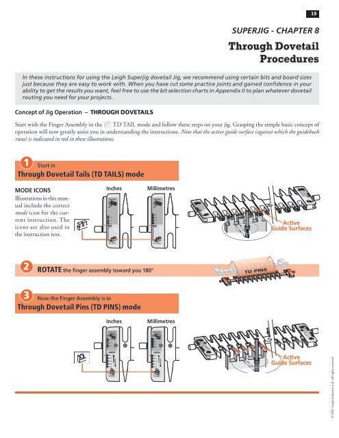
Concept of Jig Operation – THROUGH DOVETAILS<br />
Start with the Finger Assembly in the D TD TAIL mode and follow these steps on your jig. Grasping the simple basic concept of<br />
operation will now greatly assist you in understanding the instructions. Note that the active guide surface (against which the guidebush<br />
runs) is indicated in red in these illustrations.<br />
1<br />
Start in<br />
<strong>Through</strong> <strong>Dovetail</strong> Tails (TD TAILS) mode<br />
MODE ICONS<br />
Illustrations in this manual<br />
include the correct<br />
mode icon for the current<br />
instruction. The<br />
icons are also used in<br />
the instruction text.<br />
2<br />
Inches Millimetres<br />
ROTATE the finger assembly toward you 180°<br />
3 Now the Finger Assembly is in<br />
<strong>Through</strong> <strong>Dovetail</strong> Pins (TD PINS) mode<br />
Inches Millimetres<br />
TD TAILS<br />
TD PINS<br />
Active<br />
Guide Surfaces<br />
Active<br />
Guide Surfaces<br />
19<br />
© 2007 <strong>Leigh</strong> Industries Ltd. All rights reserved.
© 2007 <strong>Leigh</strong> Industries Ltd. All rights reserved.<br />
20 Chapter 8 SuperJig-12-18-24 User Guide<br />
4<br />
5<br />
2<br />
3<br />
6<br />
8-1 <strong>Through</strong> <strong>Dovetail</strong> Terminology:<br />
Pins<br />
Pin sockets<br />
Half-pins<br />
1<br />
Half-pin sockets<br />
Tails<br />
Tail sockets<br />
The pins fit in the pin sockets. Joints should almost always end<br />
each side with half-pins.<br />
8-3 For this trial you need five identical boards 3 ⁄ 4"x<br />
5- 1 ⁄2"[20x140mm] x about 8"[200mm] long. Mark inside faces for<br />
two tailboards and outside faces for three pinboards (one pinboard is<br />
a spare). Use the e7-Bush, the No. 80-8 1 ⁄2"[12,7mm]x 8° dovetail<br />
bit and 140-8 5 ⁄16 "[7,9mm] straight bit (all included with Superjig).<br />
Note: 13⁄16 "[20mm] is maximum through pin board thickness.<br />
THROUGH DOVETAIL PROCEDURES<br />
8-2 Let’s look at how to make a simple square box. When you<br />
assemble the finished pieces with the faces properly oriented, then<br />
any one of the pin ends will fit any one of the tail ends. In fact,<br />
the box can be put together in six different ways.<br />
1<br />
8-4 Fit the E-7 guidebush to the router. Align the No. 10 mark<br />
with the base mark . No guidebush adjustment is required with<br />
through dovetails. If you have a router that is incompatible with<br />
the e-Bush, you can use a standard 7 ⁄16"[11,1mm] guidebush (min.<br />
depth 1 ⁄4" see page 65) for through dovetails.<br />
Then fit the supplied 80-8 dovetail bit to the router.<br />
8-5 Clamp the finger support board in the rear clamp. 8-6 Place the finger assembly on the support brackets in<br />
the dTD PINS mode, flat on the spacer board, and with the<br />
scale set on the 1⁄2"[12,7mm] setting for now. Don’t worry about<br />
the scale’s specific meaning now. Each scale’s use will be fully<br />
explained in the appropriate section.
THROUGH DOVETAIL PROCEDURES SuperJig-12-18-24 User Guide<br />
Chapter 8<br />
8-7 Clamp a tail board against the left front side stop, top edge<br />
touching flush under the guidefingers, inside face i away from the<br />
jig body. Although you will cut tails first, adjust the guidefinger<br />
layout in dTD PINS mode. The adjustment screws are on top in<br />
this mode, and it's easier to visualize the finished joint pattern.<br />
8-9 This joint layout is just a suggestion for this trial. It has a<br />
typical, traditional symmetrical pin layout, with half-pins at each<br />
edge. The Superjig however, allows for infinite dovetail spacing.<br />
Also, boards of different thicknesses can be joined to each other<br />
as shown in this illustration. Before attempting an asymmetrical<br />
joint layout, see chapter 12.<br />
8-11 Lock the left-most guidefinger with its centre-line about<br />
1 ⁄8"[3mm] in from the left edge of the board to form a half-<br />
pin.<br />
1<br />
1<br />
21<br />
8-8 Loosen the support bracket knobs and raise the finger<br />
assembly about 1 ⁄16"[2mm] above the boards, then re-tighten<br />
the knobs. This will allow easy and accurate guidefinger adjustment.<br />
8-10 Ignoring the extreme outer guidefinger next to the scale<br />
(it just supports the router), loosen the next five guidefingers and<br />
slide them over the top of the workpiece.<br />
8-12 Leave three guidefingers over the board. Lock the rightmost<br />
guidefinger with its centre-line about 1 ⁄8"[3mm] in from<br />
the right edge of the board to form the other half-pin. Judge this<br />
distance by eye: it need not be exact. The sockets and pins will<br />
align automatically.<br />
2<br />
© 2007 <strong>Leigh</strong> Industries Ltd. All rights reserved.
© 2007 <strong>Leigh</strong> Industries Ltd. All rights reserved.<br />
22 Chapter 8 SuperJig-12-18-24 User Guide<br />
8-13 Space and lock the three remaining guidefingers as shown.<br />
Again, judge it by eye. If it looks right on the jig, the finished joint will<br />
look right.<br />
8-15 Rotate the finger assembly to DTD TAILS mode, and set<br />
it to the "ALL" position on the scale. Lower the finger assembly<br />
onto the spacer board. All TD tails are routed at this "ALL"<br />
setting. (This setting allows the dovetail bit to pass completely<br />
through all tail boards.)<br />
8-17 Place the router on the finger assembly and adjust the router<br />
until the dovetail bit tip is level with the centre of the pencil line.<br />
Note: This means the pin socket will be half a thin pencil line deeper<br />
than the thickness of the pin board, leaving minimal clean-up after<br />
assembly.<br />
Check to make sure the bit rotates freely.<br />
8-14 Tighten any other loose guidefingers.<br />
THROUGH DOVETAIL PROCEDURES<br />
8-16 Place the end of a pin board horizontally flush under the<br />
guidefingers and mark a thin pencil line partly across the tail<br />
board.<br />
REMEMBER SAFETY!<br />
8-18 Plug in the router and rout out the half-pin and pin sockets.<br />
Use only light side pressure on the guide fingers. Make sure to<br />
run the guidebush along both sides of the finger opening. Take<br />
care not to rout unwanted sockets where there are gaps between<br />
pairs of fingers . Rout only between the rounded guidefinger<br />
tips. See Hints and Tips Chapter 15.<br />
1
THROUGH DOVETAIL PROCEDURES SuperJig-12-18-24 User Guide<br />
Chapter 8<br />
8-19 Before removing the routed board from the jig, check by<br />
eye and touch to make sure no parts have been missed. Release<br />
the clamp and reverse the tail board in the jig, keeping the same<br />
inside face i away from the jig body.<br />
Rout the other end of this tail board and both ends of the second<br />
tail board in the same fashion.<br />
23<br />
8-20 Rotate the finger assembly to dTD PINS mode and set<br />
it on the 1 ⁄2"[12,7mm] mark . Do not change the guidefinger<br />
layout.<br />
1 2<br />
8-21 Finished Joint Tightness<br />
The tightness of the finished joint is determined in dTD PINS mode. The farther out toward the operator the finger assembly is<br />
set, the larger the pins will be . Moving the finger assembly in will make the pins smaller .<br />
3<br />
4<br />
1<br />
2<br />
8-22 How the TD PIN Scales Work<br />
The dimensions on the TD Pin scale indicate the major width of the pin to be routed . This matches the size of dovetail bit just<br />
used to rout the tails . The increment lines on the scale are spaced so that moving the finger assembly by one increment changes<br />
the joint glue-line gap by just 0.005"[0,125mm]. Even better, a one quarter division movement changes the fit by 0.00125"[0,03mm],<br />
a tiny one and a quarter thousandth of an inch! Once you achieve the desired joint fit, simply record the setting using the illustrations<br />
at the end of this chapter.<br />
© 2007 <strong>Leigh</strong> Industries Ltd. All rights reserved.
© 2007 <strong>Leigh</strong> Industries Ltd. All rights reserved.<br />
24 Chapter 8 SuperJig-12-18-24 User Guide<br />
8-23 Clamp a test pin board against the left hand side stop,<br />
outside face o away from the jig, with the top end flush under<br />
the guides .<br />
Place the side edge of one of the finished tail boards horizontally<br />
flush under the guidefingers and mark a thin pencil line part way<br />
across the pin board .<br />
8-25 Place the router on the finger assembly and adjust the router<br />
until the bit tip is level with the centre of the pencil line. Check<br />
to make sure the bit rotates freely.<br />
8-27 Remove the test pin board from the jig and test it for fit in<br />
one of the tail boards.<br />
Make sure the outside faces oface outward on both pieces. A firm push<br />
fit is perfect, perhaps a tap with the heel of your hand. Having to<br />
use a mallet means the joint is too tight to take glue.<br />
2<br />
1<br />
90 o<br />
THROUGH DOVETAIL PROCEDURES<br />
8-24 Unplug the router and remove the dovetail bit. Mount the<br />
included No. 140-8 straight bit to the router.<br />
8-26 Rout out the waste between the pins. Check to make sure<br />
no parts have been missed. See Chapter 15 "Hints and Tips" on<br />
how to minimize tearout.<br />
8-28 If it is too tight, move the finger assembly in (away from<br />
you) by one division on the scale. If it is only a little tight, adjust<br />
the scale by only half a division. Replace the same pin board back<br />
in the jig, carefully aligned against the same side stop. Rout off<br />
the sides of the pins and test it again for fit. Repeat as necessary<br />
to get a good fit.
THROUGH DOVETAIL PROCEDURES SuperJig-12-18-24 User Guide<br />
Chapter 8<br />
90o<br />
8-29 If the joint is loose, pull the pin board so that the angled<br />
sides of the pins and sockets jam tight together . The gap at the<br />
bottom of the pins is the amount you will have to move the<br />
finger assembly out (toward you). Reset the finger assembly and<br />
test again on the other end of this board.<br />
8-31 Rout all four ends of the pin boards, keeping the outside<br />
face o outwards. (With luck you may not have used the fifth<br />
board.)<br />
8-33 The box should be square and in plane. If it is not in plane<br />
(i.e., the side edges of each board are not in line), then either the<br />
ends of the boards are not square, the board widths are not exactly<br />
equal, or there is a concentricity problem (see 7-2 to 7-7).<br />
2<br />
1<br />
25<br />
8-30 Once the correct fit is achieved, mark the final dTD PINS<br />
scale setting on the pull-out or on one of the scale prints at the<br />
end of this chapter. Very slight variations to the scale setting may<br />
be necessary with different wood species or hardness. You can also<br />
note this on the Quick Reference pull-out card.<br />
1<br />
8-32 Assemble the box, making sure the tail boards face the<br />
proper way, i.e. tail boards inside face in i ; pin boards outside<br />
face out o . Provided you haven't already routed out the drawer<br />
bottom grooves , it doesn't matter which edge of any of the<br />
boards are at the top or bottom, the box will still fit together i.e.<br />
pin board “A” can be up either way.<br />
8-34 To form angled dovetails, refer to the Technical bulletin<br />
“How to Rout Angled <strong>Through</strong> <strong>Dovetail</strong>s on your <strong>Leigh</strong> Jig". You<br />
can download a printable file of the bulletin from our website:<br />
www.leighjigs.com/support.php. ■<br />
X<br />
A<br />
Y<br />
Y<br />
A<br />
X<br />
© 2007 <strong>Leigh</strong> Industries Ltd. All rights reserved.
© 2007 <strong>Leigh</strong> Industries Ltd. All rights reserved.<br />
26 Chapter 8 SuperJig-12-18-24 User Guide<br />
QUICK REFERENCE REMINDERS<br />
8-QR1 <strong>Through</strong> dovetails are laid out in dTD PINS mode with<br />
the finger assembly slightly raised above the spacer board and the<br />
pin board. The outside face o of the TD pins is away from the<br />
jig body.<br />
8-QR3 The finger assembly is in dTD PINS mode, with the<br />
scale set to a recorded setting (see detailed fit instructions, 8-24 to<br />
8-30). TD pins are cut with a straight bit; the only time a straight<br />
bit is used in dovetailing.<br />
This is the only one of the four main modes that puts the outside<br />
face o of the board away from the jig body.<br />
Thickness of<br />
Tail Board<br />
Thickness of<br />
Pin Board<br />
<strong>Dovetail</strong><br />
Bit<br />
up to 13/16"[21] 1/2" - 13/16" [12-20] No.80-8<br />
up to 13/16"[21] 3/8" - 5/8" [10-16] No.75-8<br />
up to 13/16"[21] 1/4" - 1/2" [6-13] No.70-8<br />
up to 13/16"[21] up to 3/8" [10] No.60-8<br />
up to 13/16"[21] up to 1/4" [6] No.50-8<br />
Numbers in brackets are millimetres<br />
Straight<br />
Bit<br />
No.140-8<br />
Guidebush<br />
Diameter<br />
e7-Bush or<br />
7/16" [11,1]<br />
diameter<br />
bush<br />
THROUGH DOVETAIL PROCEDURES<br />
8-QR2 TD tail boards are clamped vertically in the jig. The<br />
inside face i of the TD tails is away from the jig body. The finger<br />
assembly is in DTD TAILS mode, set on the “ALL” setting.<br />
There is only one setting in this mode.<br />
8-QR4 <strong>Through</strong> dovetail tails are always cut with an 8° dovetail<br />
bit to match the 8° guide finger.<br />
All through dovetail routing on the Superjig is done with the<br />
<strong>Leigh</strong> e7-Bush, or any 7 ⁄16" diameter bush (min. depth 1 /4" see<br />
page 65).<br />
1<br />
7/16"[11,1mm]<br />
8-QR5<br />
Here is a quick reference selection chart for through dovetail<br />
bits and guidebushes. Please study the bit and guidebush<br />
selection appendices for a full explanation. Note: 13⁄16"[20mm]<br />
is the maximum through pin board thickness. ■
THROUGH DOVETAIL PROCEDURES SuperJig-12-18-24 User Guide<br />
Chapter 8<br />
INCHES<br />
METRIC<br />
SAMPLE<br />
Project Settings<br />
27<br />
© 2007 <strong>Leigh</strong> Industries Ltd. All rights reserved.
© 2007 <strong>Leigh</strong> Industries Ltd. All rights reserved.<br />
28 Chapter 8 SuperJig-12-18-24 User Guide<br />
THROUGH DOVETAIL PROCEDURES
Start in<br />
Half-Blind <strong>Dovetail</strong> Pins (HB PINS) mode<br />
MODE ICONS<br />
Illustrations in this manual<br />
include the correct<br />
mode icon for the current<br />
instruction. The<br />
icons are also used in<br />
the instruction text.<br />
Inches Millimetres<br />
ROTATE the finger assembly toward you 180°<br />
<strong>SUPERJIG</strong> - <strong>CHAPTER</strong> 9<br />
Variably Spaced Half-Blind<br />
<strong>Dovetail</strong> <strong>Procedures</strong><br />
IMPORTANT! The most commonly misunderstood aspect of routing half-blind dovetails is how the dovetail bit’s<br />
depth of cut is used to adjust the joint fit, and how the angle of the bit affects that depth of cut. Review this chapter<br />
for a clear understanding of this concept.<br />
Note: Use the e7-Bush set at “10”, or any round 7/16"[11,1mm] bush (min. depth 1/4" see page 65), and any one of<br />
the five bits listed on the next page may be used for half-blind dovetails. See Appendix II “Half Blind Bit Selection”<br />
for a full description on how to select an appropriate bit.<br />
1<br />
2<br />
3 Now the Finger Assembly is in<br />
Half-Blind <strong>Dovetail</strong> Tails (HB TAILS) mode<br />
Inches Millimetres<br />
HB PINS<br />
HB TAILS<br />
Active<br />
Guide Surfaces<br />
Active<br />
Guide Surfaces<br />
29<br />
© 2007 <strong>Leigh</strong> Industries Ltd. All rights reserved.
© 2007 <strong>Leigh</strong> Industries Ltd. All rights reserved.<br />
30 Chapter 9 SuperJig-12-18-24 User Guide<br />
Board<br />
Thickness<br />
3<br />
DEPTH<br />
OF<br />
CUT<br />
6<br />
4<br />
1<br />
5<br />
2<br />
3 /8"<br />
[9mm]<br />
128-8<br />
128<br />
18 o<br />
120-8<br />
120<br />
14 o<br />
7 /16"<br />
[11mm]<br />
• Depth of cut must be as specified for each of the<br />
five bits illustrated above.<br />
• Raising the bit above its specified cutting depth<br />
will result in loose joints and may damage the jig,<br />
bit and/or guidebush. A lower setting will result<br />
in tighter joints that may not fit together.<br />
• Small Depth of Cut adjustments will change joint<br />
fit tightness. See 9-3 to 9-5 for why.<br />
112-8<br />
112<br />
12 o<br />
1 /2"<br />
[13mm]<br />
Pins h<br />
Pin sockets<br />
Half-pins<br />
VARIABLY SPACED HALF-BLIND DOVETAIL PROCEDURES<br />
9-1 Half-blind <strong>Dovetail</strong> Terminology:<br />
101-8<br />
101<br />
10 o<br />
5 /8"<br />
[16mm]<br />
Half-pin sockets<br />
Tails H<br />
DEPTH<br />
OF<br />
CUT<br />
Tail Sockets<br />
The pins fit in the pin sockets. Joints should almost always end<br />
each side with half-pins.<br />
80-8<br />
80<br />
8 o<br />
3 /4"<br />
[19mm]<br />
9-2 Important! Read This About Depth of Cut<br />
• Half-blind PINS and TAILS are routed with the<br />
same dovetail bit and must be at the same Depth<br />
of Cut.<br />
• Choose one of the five 1⁄2"[12,7mm] diameter<br />
dovetail bits shown above, and check bit selection<br />
in Appendix II.<br />
• Use the <strong>Leigh</strong> e7-Bush set at ‘10’, or any<br />
7⁄16"[11,1mm] diameter guidebush.<br />
Board<br />
Thickness
VARIABLY SPACED HALF-BLIND DOVETAIL PROCEDURES SuperJig-12-18-24 User Guide<br />
Chapter 9<br />
8˚<br />
18˚<br />
1<br />
1<br />
1<br />
1<br />
1<br />
1<br />
9-6 Bit Angle and Depth of Cut. Half-blind pins and tails<br />
are routed with the same dovetail bit, the same guidebush, and<br />
the same depth of cut. A different depth of cut requires a different<br />
angled bit. <strong>Leigh</strong> offers five different angled dovetail bits for<br />
a range of cut depths. A lesser angle, say 8˚, for a deeper cut ; a<br />
greater angle, say 18˚, for a shallower cut .<br />
PIN<br />
3<br />
2<br />
3<br />
2<br />
3<br />
2<br />
1<br />
2<br />
31<br />
9-3 Joint Fit and Depth of Cut<br />
Here’s why the depth of cut changes the fit in half-blind dovetails.<br />
Increasing or decreasing the depth of cut does not affect the<br />
pin socket width , but does affect the width of the pin that<br />
goes into the socket .<br />
9-4 Note that decreasing the bit depth makes the pin <br />
narrower while the pin socket stays the same width, producing<br />
a loose fit.<br />
Decreasing the bit depth (i.e. raise the bit into the router) produces<br />
a looser fit.<br />
9-5 Increasing the bit depth makes the pin larger while the<br />
pin socket stays the same width, producing too tight a fit.<br />
Increasing the bit depth (i.e. lower the bit) produces a tighter<br />
fit.<br />
9-7 Cumulative plus/minus tolerances in routers, bits and<br />
guidebushes, make it impossible to state exact bit depth for firsttime<br />
precision fit. All dovetail jigs require trial and error tests to<br />
attain fine fitting joints. The good news; we give a starting depth<br />
for each bit. Test and measure the successful ‘Best fit’ depth of<br />
cut or bit projection . Record for future first-time fits.<br />
© 2007 <strong>Leigh</strong> Industries Ltd. All rights reserved.
© 2007 <strong>Leigh</strong> Industries Ltd. All rights reserved.<br />
32 Chapter 9 SuperJig-12-18-24 User Guide<br />
9-8 Routing a Test Joint Use the e7-Bush or a 7 ⁄16"[11,1mm]<br />
diameter bush (min. depth 1 ⁄ 4" see page 65) and No.120-8<br />
1 ⁄2"[12,7mm] 14° dovetail bit. (80-series bits cut too deep for<br />
3 ⁄4"[20mm] boards, see HB bits, Appendix II). Select several pieces<br />
of 3 ⁄4"x5 1 ⁄2"[20x140mm] x about 8"[200mm], and the plastic<br />
bridge. Note: Half-blind pin boards must be minimum ½"[13mm]<br />
thick to clamp. Thinner boards; see 9-22.<br />
9-10 Mount the finger assembly on the support brackets in the<br />
HHB TAILS mode, flat on the spacer board, scales set on the<br />
thickness of the tail board ( 3 ⁄4"[20mm] in this instance).<br />
The HHB TAILS scale is always set at the tail board thickness.<br />
1<br />
9-12 Unlock and raise the finger assembly support brackets<br />
slightly so that the finger assembly is about 1 ⁄16"[2mm] above<br />
the boards. This will allow easy movement of the guidefingers.<br />
VARIABLY SPACED HALF-BLIND DOVETAIL PROCEDURES<br />
9-9 Clamp the spacer board in the rear clamp.<br />
9-11 Measure and mark a line on the inside face of the tail board <br />
to the bit's depth of cut as in 9-2. Clamp this test tail board in<br />
the left front clamp, against the side stop with the top edge flush<br />
under the guidefingers, and the inside face i of the drawer side<br />
away from the jig.<br />
9-13 The following joint design is suggested for this trial. It has a<br />
typical and traditional even layout of pins, with half-pins at each<br />
edge. The <strong>Leigh</strong> jig, however, allows for an infinite variety of joint<br />
designs, and boards of different thicknesses can be joined to each<br />
other as shown in this illustration. Before attempting joints of<br />
asymmetrical design, see chapter 14.<br />
1
VARIABLY SPACED HALF-BLIND DOVETAIL PROCEDURES SuperJig-12-18-24 User Guide<br />
Chapter 9<br />
9-14 Ignoring the extreme outer guidefinger next to the scale<br />
(which just supports the router), loosen enough of the adjacent<br />
guides to give the required pin socket layout. The half-pin<br />
guidefinger position illustrated will give a half-pin socket profile<br />
like that shown (dotted lines).<br />
9-16 Remember to tighten any loose guidefingers. Lower the<br />
finger assembly back onto the spacer board and workpiece. It<br />
must touch the workpiece or the depth of cut will vary and the<br />
joint won’t fit. The scale should be set on the tailboard thickness,<br />
in this case 3 ⁄4"[20mm].<br />
2<br />
9-18 Adjust the bit height until the bit tip is<br />
level with the marked line . For the first light cut<br />
move the router from right to left. Make sure you control it firmly,<br />
because it is driven in this direction by the bit. Only the tip of<br />
the bit should be cutting on the first cut . This back or climb<br />
routing leaves a very clean shoulder in side grain.<br />
1<br />
1<br />
33<br />
9-15 If the gaps between the guidefinger tails are wider than about<br />
1 ⁄8"[3mm], mark off and cut some pieces of bridge extrusion to<br />
fit into the slots in the ends of the guidefinger tails. Cut the pieces<br />
a "bare" 1 ⁄8"[3mm] more than the distance between the fingers .<br />
They are a firm friction fit.<br />
After completing a project, save the bridge pieces for future use.<br />
9-17 Attach the provided e7-Bush or a 7⁄16"[11,1mm] diameter<br />
bush securely to the router. No guidebush adjustment is required<br />
with half-blind dovetails.<br />
Fit the selected dovetail bit to the router.<br />
REMEMBER SAFETY!<br />
9-19 Now rout in and out from left to right following the guides<br />
and bridge pieces to rout out the pin sockets, leaving the tails.<br />
See Hints and Tips 15-11.<br />
2<br />
© 2007 <strong>Leigh</strong> Industries Ltd. All rights reserved.
© 2007 <strong>Leigh</strong> Industries Ltd. All rights reserved.<br />
34 Chapter 9 SuperJig-12-18-24 User Guide<br />
1<br />
9-20 Remove the test tail board, then clamp a scrap board in the<br />
front of the jig so that the top edge projects above the top face<br />
of the jig by about 1 ⁄8"[3mm] . This will keep the scrap piece<br />
below the path of the bit when routing the pin board.<br />
Remove the spacer board from the rear clamp.<br />
1<br />
9-22 Flush Drawers Place a test pin board in the left rear<br />
clamp against the side stop, its front end edge flush against the<br />
vertical scrap piece, the inside face i of the drawer front away<br />
from the jig body. The pin board is now positioned with the edge<br />
to be routed flush with the jig’s front face, correctly registered for<br />
the scale readings. For rabbeted drawer fronts, see Chapter 11.<br />
9-24 If you have difficulty leveling the finger assembly on a narrow<br />
workpiece, place a board the same thickness as the pin board<br />
under the other end of the finger assembly, but not in the rear<br />
clamp.<br />
VARIABLY SPACED HALF-BLIND DOVETAIL PROCEDURES<br />
1<br />
2<br />
9-21 If you're mounting Thin Pin Boards:<br />
Minimum recommended pin board thickness is 1 ⁄2"[13mm].<br />
Remember, No 128-8 bits rout at 3 ⁄8"[9,5mm] deep. If you rout<br />
a pin board less than minimum thickness , you need to pack<br />
the board up from the jig body. We suggest a piece of 1 ⁄4" to 3 ⁄8"[6<br />
to 9mm] plywood for this purpose .<br />
9-23 Rotate the finger assembly to hHB PINS mode. Set<br />
the HB pins scale equal to tail board thickness (i.e., same setting as<br />
tails: this example, 3 ⁄4"[20mm]). HB pins and HB tail scales are<br />
always set to tail board thickness. Make sure the finger assembly<br />
is flush and level on the pin board. The guidefingers must touch<br />
the pin board or depth of cut will vary, causing poor joint fit.<br />
9-25 Rout out the waste between the pins. Rout each space<br />
from left to right. Do not back-rout on end grain.<br />
If the bit enters on the right side of the opening there will be<br />
a very strong pull to the left, so… rout each opening in at least<br />
three or four passes, left to right.
VARIABLY SPACED HALF-BLIND DOVETAIL PROCEDURES SuperJig-12-18-24 User Guide<br />
Chapter 9<br />
90o<br />
1/64[0,3mm]<br />
9-28 When you have the proper tightness of fit, check the flushness.<br />
The tails should be under flush to the pins by no more than<br />
1⁄64"[0,3mm] to allow for cleanup (exaggerated here). Any concentricity<br />
errors in the collet and guidebush on different routers will<br />
affect this tolerance.<br />
1/64"[0,3mm]<br />
2<br />
1<br />
9-26 Remove the pin board and test the joint for fit. If the joint is<br />
loose, as shown here, you need to lower the bit by the same amount<br />
as the gap at the bottom of the pins (when the pins are pulled<br />
against the socket sides ). If the joint is too tight, raise the bit<br />
slightly. Test again. You cannot rout the same board twice with a<br />
dovetail bit, so use two fresh board ends for each test.<br />
9-30 If the tails fit in too far past the pins ends, set the hHB PINS scale toward the operator by the amount required. These<br />
adjustments for “flushness” are made only in the hHB PINS<br />
mode.<br />
1<br />
3<br />
2<br />
35<br />
9-27 Keep the test tail board that fits well, and mark it with the<br />
number of the bit you used to rout it. For quick set-up next time,<br />
clamp this tail board in the jig as a depth-of-cut gauge to show<br />
how far to lower the bit. Better yet, measure the bit projection<br />
from the end of the guidebush or guidebush flange and<br />
record this for fast set-ups in future.<br />
9-29 If the tails stand out from the pins, set the hHB PINS<br />
scale away from the operator by the amount required.<br />
9-31 To make a box, rout all four ends of the tail boards, keeping<br />
the inside face i of the tail boards away from the jig.<br />
© 2007 <strong>Leigh</strong> Industries Ltd. All rights reserved.
© 2007 <strong>Leigh</strong> Industries Ltd. All rights reserved.<br />
36 Chapter 9 SuperJig-12-18-24 User Guide<br />
9-32 Rout all four ends of the pin boards keeping the inside<br />
face i of the boards away from the jig.<br />
Note: When making drawers you may prefer to use through dovetails<br />
on the rear corners.<br />
QUICK REFERENCE REMINDERS<br />
1<br />
9-QR1 Half-blind (HB) tails: Drawer sides (tailboards) are<br />
clamped vertically in the jig. The inside face i of the drawer<br />
side goes away from the jig body. The finger assembly is in the<br />
HHB TAILS mode, set to the thickness of the drawer side. Use<br />
bridge pieces where required .<br />
Thickness of<br />
Tail Board<br />
Thickness of<br />
Pin Board<br />
Depth of<br />
Cut<br />
<strong>Dovetail</strong><br />
Bit<br />
up to 1"[26] 7/8" -1" [22] ~ 3/4" [19] No.80-8<br />
Guidebush<br />
Diameter<br />
up to 1"[26] 3/4" -up [20] ~ 5/8" [16] No.101-8 e7-Bush<br />
up to 1"[26] 5/8" -up [16] ~ 1/2" [13] No. 112-8 or<br />
up to 1"[26] 9/16" -up [14] ~ 7/16” [11] No.120-8 7/16" [11,1]<br />
up to 1"[26] 1/2" -up[12] ~ 3/8” [9] No.128-8 guidebush<br />
VARIABLY SPACED HALF-BLIND DOVETAIL PROCEDURES<br />
9-33 Assemble the box. As with through dovetails, it doesn't<br />
matter which edge of any of the boards are at the top or bottom,<br />
the box will still fit together e.g. pin board “A” can be up either<br />
way.<br />
9-QR2 Half-blind (HB) pins: Drawer fronts (pinboards) are cut<br />
with the board clamped horizontally in the jig. The inside face i of<br />
the drawer front faces away from the jig body. The finger assembly<br />
is in the hHB PINS mode, and again set on the thickness of<br />
the drawer side (but adjusted for a flush fit, see 9-29 to 9-31).<br />
7/16"[11,1mm]<br />
9-QR3 On the <strong>Leigh</strong> Superjig, all half-blind dovetails are routed<br />
using the e7-Bush or a 7 ⁄16"[11,1mm] diameter (min. depth 1 ⁄4" see<br />
page 65) bush. Instructions for end-on-end dovetails are at www.<br />
leighjigs.com/support.php. Scroll down Bulletins to “Superjig/<br />
D1600 End on End <strong>Dovetail</strong>s”. ■<br />
X<br />
A<br />
Y<br />
Y<br />
A<br />
X
<strong>SUPERJIG</strong> - <strong>CHAPTER</strong> 10<br />
One-Pass<br />
Half Blind <strong>Dovetail</strong>s<br />
Why rout “one-pass” dovetails on a variable spaced <strong>Leigh</strong> jig? Well, you just may need to reproduce or restore a<br />
late 19th or early 20th century drawer which has similar, machine made joints. Or, if you are making a lot of drawer<br />
boxes and are not so concerned with the traditional “hand-cut look”, then routing both drawer fronts and sides<br />
together does go a little faster.<br />
1 Only one mode is required:<br />
Half-Blind <strong>Dovetail</strong> Tails (HB TAILS) mode<br />
MODE ICONS<br />
Illustrations in this manual<br />
include the correct<br />
mode icon for the current<br />
instruction. The<br />
icons are also used in<br />
the instruction text.<br />
Inches Millimetres<br />
37<br />
Active<br />
Guide Surfaces<br />
© 2007 <strong>Leigh</strong> Industries Ltd. All rights reserved.
© 2007 <strong>Leigh</strong> Industries Ltd. All rights reserved.<br />
38 Chapter 10 SuperJig-12-18-24 User Guide<br />
Board<br />
Thickness<br />
4<br />
DEPTH<br />
OF CUT<br />
3<br />
6<br />
5<br />
1<br />
2<br />
7 /32"<br />
[5,56mm] 128<br />
18˚<br />
9 /32<br />
[7,13mm]<br />
120<br />
14˚<br />
3 /8"<br />
[9,52mm]<br />
112<br />
12˚<br />
MACHINE TYPE, ONE-PASS TEMPLATE HALF-BLIND DOVETAILS<br />
7 /16"<br />
[11,1mm]<br />
10-1 One-Pass Half-blind <strong>Dovetail</strong>s:<br />
Pins h<br />
Pin sockets<br />
Half-pins<br />
Half-pin sockets<br />
Tails H<br />
Tail Sockets<br />
The pins fit in the pin sockets. Joints<br />
should almost always end each side with<br />
half-pins.<br />
101<br />
10˚<br />
1 /2"<br />
[12,35mm]<br />
DEPTH<br />
OF CUT<br />
10-2 IMPORTANT!<br />
Bit depths of cut for 'one-pass' dovetails are not the same as<br />
• Depth of cut must be as specified for each of the five<br />
bits illustrated above. Note: No's 101-8, 112-8 and<br />
128-8 are optional <strong>Leigh</strong> bits.<br />
• Raising the bit above its specified cutting depth will<br />
result in loose joints and may damage the jig, bit and/or<br />
guidebush. A lower setting will result in tighter joints<br />
that may not fit together.<br />
• Small Depth of Cut adjustments will allow for joint<br />
fit tightness. See 9-3 to 9-5 for why.<br />
for variably spaced joints.<br />
80<br />
8˚<br />
Board<br />
Thickness<br />
• Choose one of the five, 1 ⁄2"[12,7 mm] diameter dovetail<br />
bits shown above.<br />
• Fit the provided <strong>Leigh</strong> e7‑Bush to the router and set<br />
at No.10, or use a standard 7 ⁄16"[11,1mm] guidebush<br />
(min. depth 1 /4" see page 65).
MACHINE TYPE, ONE-PASS TEMPLATE HALF-BLIND DOVETAILS SuperJig-12-18-24 User Guide<br />
Chapter 10<br />
8˚<br />
18˚<br />
10-3 Bit Angle and Depth of Cut. Half-blind pins and tails<br />
are routed with the same dovetail bit, the same guidebush, and<br />
the same depth of cut. A different depth of cut requires a different<br />
angled bit. <strong>Leigh</strong> offers five different angled dovetail bits for<br />
a range of cut depths. A lesser angle, say 8˚, for a deeper cut ; a<br />
greater angle, say 18˚, for a shallower cut .<br />
10-5 Routing a Test Joint You need a router, the e7‑Bush<br />
set at No.10 and note: the 80-8 1 ⁄2"[12,7mm] 8˚ dovetail bit. The<br />
No 80-8 bit routs at a shallower ~ 1 ⁄2"[13mm] depth on one-pass<br />
dovetails than on regular variably spaced joints . For this test,<br />
start with the No 80-8 bit projecting 1"[26mm] from the router<br />
base.<br />
1<br />
10-7 Superjig features two novel innovations.<br />
A Stop Rod* inserted through the fingers converts Superjig’s<br />
deep tail socket guides to function as a simple shallow fixed<br />
comb.<br />
*Patent pending.<br />
1<br />
2<br />
1<br />
39<br />
10-4 Cumulative plus/minus tolerances in routers, bits and<br />
guidebushes, make it impossible to state exact bit depth for firsttime<br />
precision fit. All dovetail jigs require trial and error tests to<br />
attain a fine fitting joint. The good news; we give a starting depth<br />
for each bit. Test and measure the successful ‘Best fit’ depth of<br />
cut or bit projection and record for future first-time fits.<br />
1<br />
10-6 This is a typical fixed template comb type jig. The comb<br />
depth is usually dimensioned to suit the most popular drawer<br />
side thickness of 1 ⁄2"[12,7mm].<br />
1<br />
3<br />
2<br />
10-8 A Spacer* slipped into the left-hand front side stop correctly<br />
offsets drawer sides from drawer fronts . The Spacer<br />
stays in place for the complete procedure.<br />
The Stop Rod stores here and the Spacer here .<br />
*Patent pending.<br />
4<br />
2<br />
5<br />
© 2007 <strong>Leigh</strong> Industries Ltd. All rights reserved.
© 2007 <strong>Leigh</strong> Industries Ltd. All rights reserved.<br />
40 Chapter 10 SuperJig-12-18-24 User Guide<br />
1<br />
2 2 2<br />
1<br />
MACHINE TYPE, ONE-PASS TEMPLATE HALF-BLIND DOVETAILS<br />
Board Width Chart<br />
Add up to ¼" [6mm] or subtract up to 1/8" [3mm]<br />
7 ⁄8 [22] 6 1 ⁄8 [156] 11 3 ⁄8 [289] (SJ-18)<br />
1 3 ⁄4 [44] 7 [178] 12 1 ⁄4 [311]<br />
2 5 ⁄8 [67] 7 7 ⁄8 [200] 13 1 ⁄8 [333]<br />
3 1 ⁄2 [89] 8 3 ⁄4 [222] (SJ-12) 14 [356] (SJ-24)<br />
4 3 ⁄8 [111] 9 5 ⁄8 [244]<br />
5 1 ⁄4 [133] 10 1 ⁄2 [267]<br />
10-9 Board Widths: To achieve equally sized half pins at each side of a fixed space joint, use chart width plus up to 1 ⁄4"[6mm],<br />
or chart width minus up to 1 ⁄8"[3mm]. This chart covers boards up to maximum width for each jig.<br />
Example: the 7"[178mm] can be up to 7 1 ⁄4"[184mm] or as small as 6 7 ⁄8"[175mm].<br />
1<br />
10-10 Slip the Spacer onto the left hand front side stop , note;<br />
No 1 to the top. With the finger assembly raised in the HHB Tails<br />
mode, clamp a drawer side in the front left side, against the Spacer<br />
and the top end edge slightly above the jig body top.<br />
Note: Drawer side thickness can be from 7 ⁄16" to 9 ⁄16"[6mm to<br />
14mm].<br />
2<br />
1<br />
10-12 Re-set the drawer side in the front clamp so that its top edge<br />
touches the guide fingers and is perfectly flush with the top face<br />
of the drawer front and the left edge is against the Spacer .<br />
! Board edges must be square.<br />
1<br />
1<br />
10-11 Place the drawer front (from 5 ⁄8" to 1" thickness [16 to<br />
25mm]) in the rear clamp. Clamp with the side edge against the<br />
left rear side stop, front end edge touching flush across the rear<br />
of the front board . Lower the finger assembly to the drawer<br />
front.<br />
! Board edges must be square.<br />
1<br />
10-13 With the scale set on 1 ⁄2"[12,7mm], raise the finger assembly<br />
to about 1 ⁄16"[2mm] above the drawer front .<br />
1
MACHINE TYPE, ONE-PASS TEMPLATE HALF-BLIND DOVETAILS SuperJig-12-18-24 User Guide<br />
Chapter 10<br />
1<br />
10-14 Slide across enough guide fingers to cover the drawer<br />
front width. Position fingers tight together and centre the group<br />
of fingers on the board .<br />
Depending on the exact board width, the outer fingers will either<br />
overhang, be inside, or flush with the board edges. Now add one more<br />
finger to the right of the group for routing the drawer side.<br />
10-16 Insert the Stop Rod through the fingers.<br />
For the first light cut move the router from right to left. Make<br />
sure you control it firmly, because it is driven in this direction<br />
by the bit. Only the tip of the bit should be cutting on the first<br />
cut . This back, or climb routing, leaves a very clean shoulder<br />
when routing side grain.<br />
90o<br />
2<br />
1<br />
10-18 Remove the boards and test the joint for fit. If the joint<br />
is loose, as shown here, lower the bit by the same amount as the<br />
gap at the bottom of the pins when the pins are pulled against<br />
the socket sides . If the joint is too tight, raise the bit slightly.<br />
Test again. You cannot rout the same board ends again with a<br />
dovetail bit, so use two fresh ends for each test.<br />
1<br />
2<br />
41<br />
10-15 Tighten the finger’s screws. Move any spare fingers so<br />
that they will support the router and tighten all loose fingers.<br />
Lower the assembly flat onto the two work pieces.<br />
REMEMBER SAFETY!<br />
10-17 Now rout in and out from left to right. Follow the guides<br />
into each finger opening to touch the stop rod. The pins, tails and<br />
sockets are formed simultaneously.<br />
1<br />
10-19 Keep the test tail board that fits well, and mark it with<br />
the number of the bit you used to rout it. For quick set-up next<br />
time, clamp this tail board in the jig as a depth-of-cut gauge to<br />
show how far to lower the bit. Better yet, measure the bit projection<br />
from the end of the guidebush or guidebush flange and<br />
record this for fast set-ups in future.<br />
3<br />
2<br />
© 2007 <strong>Leigh</strong> Industries Ltd. All rights reserved.
© 2007 <strong>Leigh</strong> Industries Ltd. All rights reserved.<br />
42 Chapter 10 SuperJig-12-18-24 User Guide<br />
1/64[0,3mm]<br />
10-20 When you have the proper tightness of fit, check the<br />
flushness. The tails should be under flush to the pins by no more<br />
than 1⁄64"[0,3mm] to allow for cleanup (exaggerated here). Any<br />
concentricity errors in the collet and guidebush on different routers<br />
will affect this tolerance.<br />
1/64[0,3mm]<br />
10-22 If the tails fit in too far past the pins ends, set the<br />
HHB TAILS scale toward the operator by half the amount<br />
required.<br />
10-24 Assemble the drawer. As with through dovetails, it doesn't<br />
matter which edge of any of the boards are at the top or bottom,<br />
the drawer will still fit together e.g. pin board “A” can be up either<br />
way.<br />
X<br />
A<br />
Y<br />
Y<br />
A<br />
X<br />
MACHINE TYPE, ONE-PASS TEMPLATE HALF-BLIND DOVETAILS<br />
10-21 If the tails stand out from the pins, set the HHB TAILS<br />
scale away from the operator by half the amount required.<br />
10-23 To make a box, repeat the procedure four times, ensuring<br />
that the drawer fronts, rears and sides are all rotated correctly in<br />
the jig, keeping the inside face i of the boards away from the<br />
jig.<br />
1<br />
10-25 Tail Boards 5/8"[16mm] and thicker.<br />
Use the same procedure to rout “one-pass” dovetails with side<br />
thicknesses from 5 ⁄8" to 1"[16 to 25mm] except:<br />
The stop rod is not used and the initial scale setting is 5 ⁄8"[16mm]<br />
for all boards . Hint: Set the e7-Bush to lower than 10 for deeper<br />
cuts in drawer fronts. ■
<strong>SUPERJIG</strong> - <strong>CHAPTER</strong> 11<br />
Rabbeted<br />
Half Blind <strong>Dovetail</strong>s<br />
Before attempting rabbeted half-blind dovetails, first master the techniques of flush half-blind dovetails in the<br />
previous two chapters.<br />
11-1 Provided the drawer front lip is 3 ⁄8"[9,5mm] or less in each<br />
direction , you can mount and rout rabbeted drawer fronts and<br />
sides exactly the same way as flush drawer fronts, except...<br />
1<br />
1<br />
1<br />
11-3 This brings the pin ends exactly in line with the front jig<br />
face , ensuring that the scale reading is accurate.<br />
2<br />
3<br />
11-2 Rabbeted Pins You will need to block the scrap stop in the<br />
front of the jig out from the jig’s front face by exactly the width of the<br />
rabbet .<br />
An easy accurate way to do this is to rabbet the end of the scrap<br />
piece ➁ vertically over a dado blade or router bit at the same time<br />
as you rabbet the drawer front (horizontally) ➂.<br />
2<br />
1<br />
3<br />
11-4 If the rabbet width is greater than the top machined side<br />
stop width of 3 ⁄8" ➁, the drawer side (tailboard) must be blocked<br />
away from the front side stop (see 10-5 below) by exactly the width<br />
of the rabbet minus 3 ⁄8" ➂. For example, a 5 ⁄8" rabbet would<br />
require the tailboard to be offset by an additional 1⁄4" ➂.<br />
Make a spacer block of the required width and…<br />
2<br />
3<br />
=<br />
=<br />
1<br />
43<br />
© 2007 <strong>Leigh</strong> Industries Ltd. All rights reserved.
© 2007 <strong>Leigh</strong> Industries Ltd. All rights reserved.<br />
44 Chapter 11 SuperJig-12-18-24 User Guide<br />
3<br />
11-5 Stick the block to the jig face with double-sided tape,<br />
making sure it touches the side stop.<br />
11-7 Make sure you select a dovetail bit that has a working depth<br />
of cut less than the rabbet height. Otherwise, you will rout into the<br />
rabbet.<br />
Note: Rabbeted one-pass dovetails:<br />
The lip of a drawer front makes it impractical to rout rabbeted halfblind<br />
dovetails in one pass. Each piece would have to be routed separately,<br />
in which case it is easier to use the variable spaced method.<br />
RABBETED HALF-BLIND DOVETAILS<br />
11-6 The drawer side will now be stepped in from the side stop<br />
by the width of the rabbet, bringing the sockets in line with<br />
the pins.<br />
11-8 It is difficult to clean up the drawer sides and front corner<br />
after assembling a rabbeted drawer, so make sure the fit is flush<br />
before you complete the drawers See 9-28 to 9-30. ■