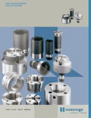
2285A Precision Length Control Draw-In Collets and Step Chucks
2285A Precision Length Control Draw-In Collets and Step Chucks
2285A Precision Length Control Draw-In Collets and Step Chucks

You also want an ePaper? Increase the reach of your titles
YUMPU automatically turns print PDFs into web optimized ePapers that Google loves.
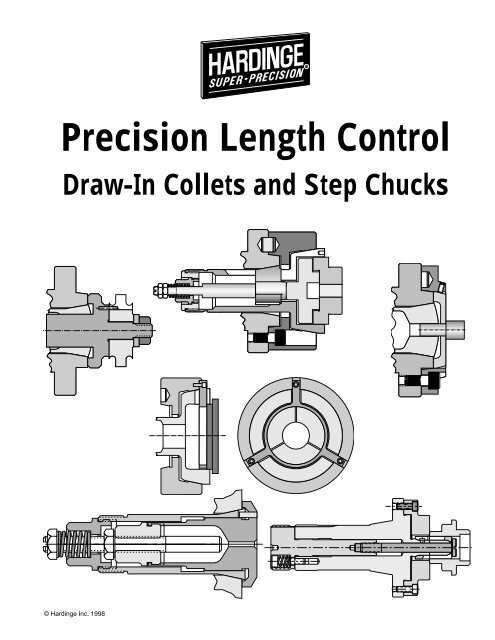
<strong>Precision</strong> <strong>Length</strong> <strong>Control</strong><br />
<strong>Draw</strong>-<strong>In</strong> <strong>Collets</strong> <strong>and</strong> <strong>Step</strong> <strong>Chucks</strong><br />
© Hardinge <strong>In</strong>c. 1998
<strong>In</strong> The Beginning<br />
the first collet was patented by Herick Aiken around 1839. It was used in a h<strong>and</strong> held<br />
device to hold a needle. The collet was eventually used on lathes <strong>and</strong> milling machines.<br />
Henry Hardinge developed the production method for making "True-hole" collets<br />
around the turn of the century (1906). Today there are basically two style collets –<br />
the draw-in-to-close <strong>and</strong> the push-to-close.<br />
The <strong>Draw</strong>-in Collet<br />
is best suited for parts where the diameters have to be machined concentric to the<br />
chucking diameter. The draw-in collet is not very accurate for holding lengths in relationship<br />
to the part shoulder, which locates against the collet, face, step, or internal<br />
stop. Because of its ability to hold parts concentric, the draw-in collet is generally used<br />
for precision machining.<br />
The Push-to-Close Collet<br />
is not very accurate for holding parts concentric, but is fairly accurate at holding lengths.<br />
The collet does not move when the collet is closed. The collet is shouldered <strong>and</strong> a<br />
sleeve moves forward, pushing against the collet head angle to close.<br />
The Purpose<br />
of this publication is to help you learn about precision length control. Throughout the years, devices have been developed<br />
to help reduce (<strong>and</strong> sometimes eliminate) the length control problems associated with draw-in collets. We will show<br />
you how these devices work <strong>and</strong> how to apply them to your particular application. Basic length control methods are easy<br />
to learn. We will begin with the most fundamental concepts <strong>and</strong> build on them until you have a thorough knowledge of<br />
precision length control for draw-in collets <strong>and</strong> step chucks.<br />
Hardinge ®<br />
has been designing <strong>and</strong> manufacturing collets <strong>and</strong> workholding devices for over 100 years. Let us use our technical<br />
expertise to help you solve your workholding problems. We can manufacture any of the devices shown in this publication<br />
to meet your specific needs. You will find a majority of the items illustrated on our shelves waiting for your order – instant<br />
solutions to your specific needs.<br />
Please<br />
read <strong>and</strong> study the information <strong>and</strong> illustrations. If you have any questions, give us a call, <strong>and</strong> we'll be glad to help<br />
(800-843-8801).<br />
2<br />
Collet Stops .................................... 4<br />
Collet-<strong>Step</strong> ..................................... 4<br />
Collet-Dead-<strong>Length</strong> ® ................. 9-10<br />
Fixture Plate ................................ 5-6<br />
Exp<strong>and</strong>ing <strong>Collets</strong> ........................ 15<br />
Methods Summary ....................... 12<br />
Mic <strong>and</strong> Stack ................................. 4<br />
Table of Contents<br />
Herrick Aiken Collet<br />
December 27, 1839<br />
Off-the-Spindle Fixturing ......... 13-14<br />
Pin <strong>and</strong> Plate <strong>Step</strong> <strong>Chucks</strong> ......... 8-9<br />
Reason for the Problem ................. 3<br />
1:3 Rule of Thumb .......................... 3<br />
Stop Plates .................................. 6-7<br />
<strong>Step</strong> <strong>Chucks</strong>—Dead <strong>Length</strong> .... 10-11<br />
<strong>Step</strong> <strong>Chucks</strong>—Spider Stop .......... 11
Why Part <strong>Length</strong> <strong>Control</strong>?<br />
The draw-in lathe collet has always been noted for holding parts concentric but is not very accurate for holding part<br />
lengths. Anyone who has operated a lathe with draw-in style collets spends considerable time trying to overcome the<br />
inherent part length problem. Many times, additional costly operations are required to hold precision lengths. Therefore,<br />
much time <strong>and</strong> money is saved when lengths are controlled during the initial or secondary lathe operation.<br />
Typical Lathe Operation – Face the Part<br />
Let's look at a typical part <strong>and</strong> the related length control problems. The draw-in<br />
collet grips on the chucking diameter "A" which varies ±.002" (figure 1). The<br />
only machining operation required is to face the part while holding the "B" length<br />
dimension to ±.001" (figure 2). We insert the setup part in the collet <strong>and</strong> face it<br />
to exactly .7500" from the shoulder "B".<br />
After making four pieces, we check our fifth piece <strong>and</strong> find the shoulder length<br />
is .006" less than our setup piece, <strong>and</strong> is below the print specifications (figure<br />
2). Being concerned, we check the shoulder length of the other parts. The fourth is +.003" over,<br />
the third is -.001" under (which is okay), the second is - .002" under, <strong>and</strong> the first one is fine. The<br />
chucking diameters "A" were all within the ±.002" print specification.<br />
Why Did The <strong>Length</strong> Vary?<br />
First let's look at the collet. It has a 10° head angle. If the .500" chucking diameter (figure 3) is<br />
reduced by .001" to .499", the collet will pull back into the spindle an additional .003" before<br />
3<br />
Setup<br />
Diameter<br />
Smaller<br />
Diameter<br />
Exact<br />
Long<br />
.750 .753<br />
Fixed<br />
Fixed<br />
Larger<br />
Diameter<br />
Short<br />
.747<br />
Fixed<br />
Note: Each style collet has a maximum chucking diameter variation it can grip before a different size collet is required.<br />
HQC ® Quick-Change collets can h<strong>and</strong>le a much greater chucking diameter variation than solid <strong>and</strong> master collets.<br />
A<br />
B<br />
1<br />
2<br />
.750<br />
±.001<br />
firmly gripping the part (figure 4). If the chucking diameter of the part is .501", the part will not be drawn into the spindle<br />
as far as the .500" diameter part. It will actually be .003" further out than the setup piece (figure 5).<br />
There are two fixed items in this setup; one is the spindle <strong>and</strong> the other is the facing tool. When the chucking diameter is<br />
.001" smaller, the part is pulled .003" further into the spindle. When faced, the finished part will be .003" longer than the<br />
setup piece (figures 3 <strong>and</strong> 4). The facing tool does not move; only the collet with the part moves. The reverse is also true;<br />
if the chucking diameter is .001", larger, the part will be .003" further out than the setup piece. After facing, it will be .003"<br />
shorter (figure 5).<br />
<strong>In</strong> Summary, always remember the 1:3 Rule of Thumb for a 10° Closing Angle: For every .001" variation on the<br />
chucking diameter of a workpiece, the finished length will vary .003" in relationship to the spindle face.<br />
.500" Chucking<br />
Diameter<br />
4<br />
.499" Chucking Dia.<br />
(Part & collet draws<br />
into Spindle)<br />
Chucking Diameter Tolerance Relationship to Expected <strong>Length</strong> Variations<br />
Diameter Tolerance .0001" .00033" .0005" .001" .002" .004" 005"<br />
<strong>Length</strong> Variation .0003" .001" .0015" .003" .006" .012" .015"<br />
5<br />
Exaggerated Views<br />
.501" Chucking Dia.<br />
(Part & Collet farther out<br />
from spindle)<br />
3
Methods That Do Not Hold <strong>Precision</strong> <strong>Length</strong>s<br />
Is a solid collet stop the answer? No! The stop will make certain that each part<br />
locates in exactly the same place, in relationship to the collet. What happens to the<br />
collet when the chucking diameter is .001" smaller than the set up piece? It pulls<br />
back into the spindle .003". The stop is attached to the collet, therefore, it <strong>and</strong> the<br />
part, go with the collet (figures 6 <strong>and</strong> 7).<br />
How about a step collet? The step is in the collet; the collet moves whenever the<br />
chucking diameter is not exactly the same as the setup piece, therefore, it will not<br />
work either (figure 8).<br />
Will a draw tube stop work? No! The draw tube stop is attached to the inside of<br />
the tube with compression rings or exp<strong>and</strong>ed "O" rings. The draw tube pulls the<br />
collet back into the spindle. If the second part is smaller or larger<br />
than the setup piece, the draw tubes position will vary. <strong>Length</strong> control<br />
is impossible (figure 9).<br />
;<br />
9<br />
; "Mic" <strong>and</strong> Stack- The Hard Way to Hold Part <strong>Length</strong>s<br />
While walking through a shop, we saw a lathe operator with several stacks of<br />
parts arranged on his work cart. We asked what the stacks were for. "<strong>Length</strong><br />
control" was his answer.<br />
He explained that the workpiece had a .500" chucking diameter<br />
"A" (figure 10) <strong>and</strong> it varied a total of -.003". The shoulder-to-face<br />
length tolerance "B" was -.002". Using the "1:3<br />
Rule-of-Thumb", it was determined that the variation on the<br />
chucking diameter would result in a length variation of .009",<br />
which was unacceptable.<br />
To hold the print lengths on this job, the operator must "mic" the chucking diameter of each piece before machining <strong>and</strong><br />
group all those with the same dimension together. A -.0005" variation on the chucking diameter would give a .0015"<br />
length variation. This would allow for a .0005" cushion within the .002" finish part length tolerance (see above chart).<br />
After measuring all the parts there would be a total of 6 stacks.<br />
The initial setup was done using the part with the largest chucking diameter from the first group. The facing tool was set<br />
to the low side of the print dimension's tolerance. <strong>In</strong> this way, the part with the smallest chucking diameter would have<br />
had a length that would fall within the print tolerance. After finishing with the first group, the operator went on to the next<br />
group, gripped the part with the largest chucking diameter <strong>and</strong> reset the facing tool the same way that was done on the<br />
first group, etc. Six setups had to be made. Note: If the chucking diameter had varied ±.003" twelve (12) setups would<br />
have been necessary.<br />
Does this method work? Yes, but it is not very productive <strong>and</strong>, unfortunately it is very common practice throughout the<br />
machining industry.<br />
What are the Alternatives? Hold a tighter tolerance on the chucking diameter during the first operation machining.<br />
This could allow the second operation finish length tolerance to be held. The cost of holding the first operation could<br />
increase the production cost considerably (see chart on previous page as a guide when holding chucking diameters).<br />
Are there better methods? Yes. They're on the following pages.<br />
4<br />
A<br />
6<br />
7<br />
10<br />
8<br />
B<br />
Part Groups Needed to Hold <strong>Length</strong>s<br />
1st 2nd 3rd 4th 5th 6th<br />
.5000" .4995" .4990" .4985" .4980" .4975"<br />
.4995" .4990" .4985" .4980" .4975" .4970"
Methods That Hold <strong>Precision</strong> <strong>Length</strong>s<br />
There are several methods for part length control, each having its advantages as well as disadvantages. Throughout the<br />
remainder of this publication various methods of length control will be presented. We will start with the simplest methods,<br />
fixture plates, <strong>and</strong> move on to the more complex methods. Once these methods are understood, precision length control<br />
will no longer be a problem.<br />
The Part is similar to the one we started with. It has a .500" (±.002") chucking<br />
diameter that is 1.5" long with a .750" diameter hub which is .750" long. The only<br />
machining that takes place is facing the part to hold the length from the back<br />
shoulder to the face; .750" (-.001") (figure 11).<br />
Choices: Let's take a look at the possible choices we have. The "Mic <strong>and</strong><br />
Stack" will require 12 separate stacks. The chucking diameters of the parts in<br />
each stack can only vary a maximum of .00033" if we are to hold the .001" length tolerance. We will also have to perform<br />
12 separate setups. This is doable but time consuming <strong>and</strong> impractical. Let's investigate the use of a fixture plate.<br />
Precise <strong>Length</strong> <strong>Control</strong> Using Fixture Plates<br />
Most people think of a fixture plate as a base for fixturing irregular shaped parts which<br />
cannot be held with a collet, step chuck, or a jaw chuck. Here is another use — a backing<br />
plate for a workpiece that has a shoulder <strong>and</strong> a long chucking diameter.<br />
How to Make a Backing Plate<br />
• Remove the flange from the fixture plate. Then hold the outside diameter of the fixture<br />
plate in a step chuck <strong>and</strong> counterbore the back face enough to clear the face of the<br />
collet when it is opened <strong>and</strong> closed (figure 13).<br />
• Remove the step chuck <strong>and</strong> closer.<br />
• Mount the collet <strong>and</strong> adjust it for the chucking diameter.<br />
• Remove the workpiece.<br />
• Mount the counterbored fixture plate to the spindle of the machine (the 5C<br />
Plates are threaded or taper locked, the 16C, 20C, 25C Plates are bolted<br />
onto the spindle).<br />
• Rough drill <strong>and</strong> then finish bore <strong>and</strong> chamfer the hole. The bore should be<br />
.005" to .010" larger than the largest chucking diameter of the workpiece.<br />
• Lightly face the fixture plate to make sure it is perpendicular to the centerline<br />
of the spindle.<br />
How to Use a Backing Plate<br />
.500"<br />
±.002<br />
Fixture Plate<br />
1.500"<br />
.750"<br />
-.001<br />
5C 16C<br />
Fixture Plates<br />
• Load the part through the fixture plate into the collet.<br />
• Close the Collet. As the collet closes, the part is drawn back against the face of the fixture plate with a tremendous<br />
amount of force.<br />
Advantages: This is one of the best methods for holding lengths. Any part that has a shoulder <strong>and</strong> a long chucking<br />
diameter can use this method to help eliminate chatter, improve surface finish <strong>and</strong> extend tool life. The tremendous force<br />
exerted when pulling the part back against the plate stabilizes the part. A part held in a collet does not have this<br />
advantage.<br />
Disadvantages: There is one major drawback with a fixture plate – the cost. Fixture plates are expensive. A different one<br />
is required for each size part, even when the chucking diameter is only 1/64" larger, <strong>and</strong> they will not work for parts<br />
without long shanks.<br />
5<br />
12<br />
Counter Bore<br />
Workpiece<br />
Drill & Bore<br />
Skim Cut<br />
Face<br />
11<br />
.750"<br />
13
Summary: The spindle of our lathe is fixed;<br />
only the collet moves in <strong>and</strong> out as the chucking<br />
diameter of the workpiece varies. For precise<br />
length control, the workpiece must locate<br />
against some portion of the spindle face or<br />
spindle seat, or against something that locates<br />
against these surfaces. (figures 14 & 15)<br />
Precise <strong>Length</strong> <strong>Control</strong> Using Stop Plates<br />
The fixture plate is the most basic method of length control. It is the basis for all other length control devices. Let's take a<br />
look at the Stop Plate. It overcomes the high cost factor of the fixture plate with very little loss<br />
in efficiency.<br />
16<br />
The Stop Plate is nothing more than a glorified hardened <strong>and</strong> ground washer (figure 16 for<br />
commercial stop plates).<br />
How To Make a Stop Plate<br />
• Counterbore the washer on one side large enough for the collet to open <strong>and</strong> close without<br />
touching the back of the plate (figure 17).<br />
• Grind the two faces of the plate parallel to each other.<br />
• Bore the stop plate .005" to .010" larger than the part's chucking diameter.<br />
How To Use a Stop Plate<br />
• Clean both sides of the plate <strong>and</strong> the face of the spindle.<br />
• Push the part through the backing plate.<br />
17<br />
Stop<br />
Plate<br />
• Place the shank of the part in the collet <strong>and</strong> push the whole assembly back<br />
firmly against the face of the spindle.<br />
• Close the collet. This action pulls the part <strong>and</strong> the stop plate firmly against the<br />
face of the spindle.<br />
Counter<br />
Bore<br />
Advantages<br />
Spindle<br />
• <strong>In</strong>expensive – Commercial stop plates are available in sets of 3 with 1/8" bores.<br />
They take up very little space for storage. A basic set can be made in 1/16" increments up to the maximum collet<br />
capacity.<br />
• Maximum stability – This is due to tremendous pressure exerted against the parts shoulder when the collet closes.<br />
This helps eliminate tool chatter <strong>and</strong> allows machining of small, long diameter parts, with shoulders, that normally<br />
cannot be successfully machined by holding them in a st<strong>and</strong>ard collet.<br />
Disadvantages<br />
• Chips & dirt – Although this process is excellent for short run jobs (5 to 25 pieces), they are very time consuming<br />
when machining large quantities. If chips are not thoroughly cleaned from both faces of the plate <strong>and</strong> the face of the<br />
spindle, perpendicularity cannot be held accurately. Even lengths can vary, depending upon chip size which gets<br />
between the spindle <strong>and</strong> plate.<br />
• Lost production time – The operator h<strong>and</strong>les two pieces all the time. The part must be assembled in the stop plate<br />
<strong>and</strong> then in the collet. The fixture plate method does not have this problem because it is one solid piece mounted to<br />
the spindle. Simply clean the face of the fixture plate <strong>and</strong> insert the part.<br />
• Is there cure for this problem? Yes, a Spindle Mount.<br />
6<br />
14<br />
15<br />
16C<br />
5C
Precise <strong>Length</strong> <strong>Control</strong> Using Spindle-Mounted Stop Plates<br />
The spindle mount is used to hold stop plates firmly against the spindle face. Stop plates can be quickly removed,<br />
replaced <strong>and</strong> centered in minutes. One spindle mount is used for an infinite number of stop plates with different size<br />
bores.<br />
The Spindle Mount for the stop plates is threaded, or taper-locked on the 5C spindle; it is<br />
bolted on the 16C spindle (A2-5).<br />
How To Assemble the Stop Plate to the mount (figures 18 <strong>and</strong> 19).<br />
• Clean all surfaces.<br />
• Slide the part through the plate into the collet. Push <strong>and</strong> hold them against the face of<br />
spindle.<br />
• Close the collet.<br />
• Adjust the four taper point screws on the 5C mount centering the plate around the part.<br />
Use the flat point screws on the 16C mount to center the plate (the set screws push the<br />
plate against the face of the spindle).<br />
• Open the collet <strong>and</strong> pull the part out 1/4" or more <strong>and</strong> finely adjust plate to center.<br />
How To Use the Spindle-Mounted Stop Plate<br />
• Clean face of stop plate <strong>and</strong> the shoulder of the part.<br />
• Open the collet.<br />
• Load the part through the stop plate <strong>and</strong> push the part firmly against the plate.<br />
• Close the collet.<br />
Advantages: We now have all the advantages of the fixture plate at an extremely low<br />
cost. Chips cannot get between the face of the backing plate <strong>and</strong> the face of the spindle.<br />
You're ready for precise length control <strong>and</strong> high production work.<br />
Disadvantages: The parts must have long chucking diameters.<br />
Summary: We have located the stop plate against the face of the spindle <strong>and</strong> the shoulder of the part against its face of<br />
the plate. The spindle doesn't move; only the collet moves. We have again achieved precise length control.<br />
20<br />
Here are some other examples<br />
to stimulate your imagination.<br />
21<br />
19<br />
18<br />
5C Spindle Mount<br />
16C Spindle Mount<br />
7
Touch-The-Spindle <strong>and</strong> Pin-Style <strong>Step</strong> <strong>Chucks</strong><br />
Precise length control requires the part to locate directly against the spindle or against a device which locates against<br />
the spindle. With a little imagination you will see other ways to accomplish this task. Any device which locates against the<br />
spindle must have its part locating surface "trued up" with a light facing cut. Make certain not to machine the face of the<br />
actual spindle. Here are some other examples of touching the spindle to hold lengths:<br />
22 23 24<br />
Pin <strong>Step</strong> <strong>Chucks</strong> are an excellent method of length control. The illustration in figure 24 shows the concept<br />
very well.<br />
• Drill holes in the step chuck on the diameter of the locating surface on the part.<br />
• Mount the closer on the spindle of the machine which<br />
is going to run the part.<br />
• Mount the step chuck in the closer (key of spindle<br />
aligned to keyway of step chuck).<br />
• Center-punch the closer through the holes in the step<br />
chuck.<br />
• Remove step chuck <strong>and</strong> closer.<br />
• Drill <strong>and</strong> tap the closer.<br />
• Threaded hex pins are made <strong>and</strong> assembled.<br />
• Mount the closer <strong>and</strong> step chuck.<br />
• <strong>In</strong>sert pins into the face of the step chuck <strong>and</strong> close<br />
the step chuck on round pins.<br />
• Lightly face the hex pins to make them perpendicular<br />
to the spindle centerline.<br />
• Remove round pins from the step chuck.<br />
• Load the part <strong>and</strong> close the step chuck.<br />
• Machine the part.<br />
Side-Pin <strong>Step</strong> Chuck: The pins are brought in from the side<br />
of the closer. This method requires more mass on the closer<br />
(figure 26).<br />
• Make a heavy-walled ring <strong>and</strong> thread or press it on the<br />
closer.<br />
• Drill <strong>and</strong> tap locating pin holes through the side of the closer<br />
assembly.<br />
• Drill large clearance holes in the step chuck for pin clearance<br />
(as shown) or widen slots to clear the pins.<br />
• Assemble the pins <strong>and</strong> face to make them perpendicular<br />
to the spindle centerline.<br />
8<br />
25<br />
26<br />
3 or 6 holes drilled <strong>and</strong><br />
tapped on locating face<br />
diameter<br />
Hex Pins threaded<br />
into closer<br />
Ring<br />
Pin<br />
Part<br />
3 or 6 holes drilled on<br />
locating face diameter<br />
to clear hex stop pins<br />
Workpiece
27<br />
Plate<br />
Part<br />
Plate-Style Pin <strong>Step</strong> <strong>Chucks</strong>: These are made with plates bolted to large pins.<br />
The plate is then machined to the configuration of the locating surface of the part<br />
(figure 27).<br />
External Spider-Style <strong>Step</strong> <strong>Chucks</strong>: (figure 28)<br />
This method<br />
has slots on the 28<br />
Plate<br />
face of the<br />
closer. The spider<br />
plate is<br />
made from<br />
heavy sheet<br />
metal <strong>and</strong><br />
bolted to the<br />
face of the slots<br />
of the closer.<br />
Part<br />
Dead-<strong>Length</strong> ® <strong>Collets</strong> <strong>and</strong> <strong>Step</strong> <strong>Chucks</strong><br />
29 Spindle<br />
<strong>In</strong>ner Collet<br />
Locates against<br />
spindle<br />
30<br />
Spring<br />
Holds inner collet<br />
against spindle<br />
Outer Collet<br />
Pulls back to close inner collet<br />
(no part in this view)<br />
The Dead-<strong>Length</strong> ® Collet, patented by Hardinge ® , brings everything that we have discussed together into one uniquely<br />
designed, high production, precision length control device.<br />
How the Dead-<strong>Length</strong> Collet Works: (figures 29 <strong>and</strong> 30)<br />
• The inner collet locates against the spindle face.<br />
• The outer collet is pulled back by the collet closer. This action closes the outer collet down on the inner collet, gripping<br />
the part. This action also draws the inner collet firmly back against the face of the spindle.<br />
• The stop in the inner collet, along with the adapter in the outer collet, <strong>and</strong> the spring <strong>and</strong> nut hold the whole assembly<br />
together. When the collet closer moves forward to open the collet, the spring holds the face of the inner collet against<br />
the spindle face.<br />
• The spring adjustment is critical. If the spring is compressed too tightly, the whole assembly will be pushed forward<br />
when opening the collet, thus moving the face of the inner collet away from the spindle face, allowing chips to fall in<br />
the gap.<br />
NOTE: If there are problems holding lengths, this is the first thing to check. Back off the spring nut one turn <strong>and</strong> check<br />
again for inner collet push out.<br />
9
Emergency <strong>In</strong>ner <strong>Collets</strong> come st<strong>and</strong>ard with the Dead-<strong>Length</strong> ® collet assembly. These soft inner collets are used for<br />
short run production jobs.<br />
How Emergency <strong>In</strong>ner <strong>Collets</strong> Are Used<br />
• Pins are inserted in the appropriate holes in the face of the<br />
collet for machining.<br />
• The collet closer is then adjusted like a normal emergency<br />
collet.<br />
• The bore is machined to the exact size of the chucking diameter<br />
of the workpiece (high side of its tolerance).<br />
• After machining remove the assembly from the spindle.<br />
• Take the pins out <strong>and</strong> debur the inner collet.<br />
• Reassemble <strong>and</strong> mount the assembly back in the spindle.<br />
Hardened <strong>and</strong> Ground <strong>In</strong>ner <strong>Collets</strong> are also available.<br />
These eliminate the time needed to bore out the collet. The collet<br />
is hardened <strong>and</strong> will last for years under normal machining conditions.<br />
The emergency collet is intended for short run jobs, or when<br />
there is no hardened <strong>and</strong> ground collet on h<strong>and</strong>.<br />
10<br />
32<br />
34<br />
Other Style Dead-<strong>Length</strong> ® <strong>Collets</strong> <strong>and</strong> <strong>Step</strong> <strong>Chucks</strong><br />
Dead-<strong>Length</strong> <strong>In</strong>ner <strong>Step</strong> Chuck Assembly<br />
33<br />
35<br />
31<br />
16C Dead-<strong>Length</strong> Thru-Collet<br />
The Dead-<strong>Length</strong> Thru-Collet is used for bar stock <strong>and</strong> has the same precise length control capabilities. The<br />
Thru-Collet feature does reduce the maximum diameter stock which can be held with the collet. Bar stock is fed thru<br />
the open collet to the revolving stop. The inner collet does not draw back when the collet closes, therefore, the length<br />
is held very accurately even when the stock diameter varies (figures 32 <strong>and</strong> 33).<br />
Dead-<strong>Length</strong> <strong>Step</strong> Chuck<br />
Spindle<br />
16C Dead-<strong>Length</strong> <strong>Step</strong> Chuck<br />
The Dead-<strong>Length</strong> <strong>Step</strong> Chuck is nearly identical to the Dead-<strong>Length</strong> collet except that it has a large diameter head for<br />
gripping parts up to 2-3/4" <strong>and</strong> to a depth of 1/2". This device is for light machining operations only (figures 34 <strong>and</strong> 35).<br />
For heavier duty machining, a step chuck must be contained with a step chuck closer. The Dead-<strong>Length</strong> Spider-Stop<br />
step chuck should be used for those applications.
The 16C Dead-<strong>Length</strong> ® Spider-Stop <strong>Step</strong> Chuck uses a<br />
heavy-duty finned stop that locates against the collet seat<br />
in the spindle. The spider is internally threaded to receive<br />
the stop button. The stop button is machined to conform<br />
to the part <strong>and</strong> its locating surface (figure 36).<br />
This device is excellent for st<strong>and</strong>ard <strong>and</strong> heavy-duty machining.<br />
There are two models, one for up to 3" diameter<br />
work <strong>and</strong> the other for up to 4" diameter work.<br />
If you have a need for holding larger diameter workpieces,<br />
Hardinge ® has a special collet department which can meet<br />
your requirements.<br />
16C HQC ® -42 Quick-Change Collet Dead-<strong>Length</strong> ®<br />
Spider-Stop Assembly also uses the collet seat in the spindle<br />
to locate the length control device. The Spider-Stop is internally<br />
threaded, 1/2"-20 TPI, but a stop button is not supplied.<br />
Advantages of Dead-<strong>Length</strong> Systems<br />
• Commercially available — off-the-shelf delivery.<br />
• Precise length control up to the capacity of the collet or step chuck.<br />
• <strong>In</strong>expensive emergency collets.<br />
• Hardened <strong>and</strong> ground inner collets.<br />
• Available for the Hardinge HQC ® Quick-Change Collet Systems.<br />
• Spider-Stop systems capable of heavy stock removal.<br />
Disadvantages<br />
• None.<br />
36<br />
Spider Stop<br />
Locates against<br />
spindle collet seat<br />
Patented<br />
Stop Button<br />
Summary: The Dead-<strong>Length</strong> collets <strong>and</strong> step chucks all use either the face of the spindle or the collet seat to guarantee<br />
precision length control. Because they are commercially available there is no lost production due to development in your<br />
own facility. The appropriate components are hardened <strong>and</strong> ground to assure maximum life of the product which may not<br />
be possible in your own facility.<br />
37<br />
Patented<br />
Part<br />
11
We have come a long way in our underst<strong>and</strong>ing of length control <strong>and</strong> should be familiar with the following methods, as<br />
well as their advantages <strong>and</strong> disadvantages. The chart below summarizes what has been covered.<br />
There are other methods which do not use the fixed spindle for length control. One method is used for parts which are<br />
difficult to hold <strong>and</strong> are usually mounted to a face plate or held with a very elaborate fixture. We call this method "Offthe-Spindle"<br />
or "Round Fixturing".<br />
12<br />
Method Advantage Disadvantage<br />
"Mic" & Stack Doable Extremely time consuming<br />
<strong>In</strong>accurate - Not considered precise<br />
Fixture Plate Precise length control Part must have a long chucking diameter<br />
Excellent for long run jobs with a locating shoulder - Fixture plates<br />
Available for the 5C & 16C spindles are expensive<br />
Stop Plates Precise length control Part must have long chucking diameter<br />
<strong>In</strong>expensive with a locating shoulder - Time Consuming<br />
Stabilizes the part Subject to chips <strong>and</strong> dirt behind plate<br />
Reduces chatter - Improves finish Not practical for long run jobs<br />
Spindle Mounted Precise length control Parts must have long chucking diameter<br />
Stop Plates Reasonably priced<br />
Excellent for short <strong>and</strong> long runs<br />
Plates quickly changed for new job<br />
Quick part loading<br />
Reduces chatter - Improves finish<br />
Available for the 5C & 16C Spindle<br />
with a locating shoulder<br />
Touch-the-Spindle Precise length control Requires custom made devices to<br />
- Pin <strong>Step</strong> <strong>Chucks</strong> - Quick part loading locate against the spindle<br />
Dead-<strong>Length</strong> ® Precise length control None<br />
Collet <strong>In</strong>expensive inner collet<br />
Quick setup<br />
Available for the 5C & 16C spindle<br />
Dead-<strong>Length</strong> ® Precise length control for bar stock Reduces maximum stock capacity<br />
Thru-Collet <strong>In</strong>expensive inner collet<br />
Quick setup<br />
Available for the 5C, 16C & 20C spindles<br />
of the inner collet<br />
Dead-<strong>Length</strong> Precise length control - nexpensive Light machining only<br />
<strong>Step</strong> Chuck inner step chuck - Available for<br />
5C, 16C & 20C spindles<br />
2-3/4" maximum diameter part<br />
Dead-<strong>Length</strong> Precise length control 4" Maximum diameter work<br />
Spider-Stop Heavy duty machining <strong>In</strong> stock for the 16C Spindle<br />
<strong>Step</strong> Chuck Quick part loading Can be special ordered for others<br />
HQC ® Quick- Precise length control for HQC ® Must be installed before HQC spindle<br />
Change Dead- Quick part loading mount - <strong>In</strong> stock for 16C <strong>and</strong> A2-5<br />
<strong>Length</strong> Spider- Spindles - Can be special ordered<br />
Stop Assembly for others<br />
There Are Other Ways!
38<br />
Closer<br />
Spider<br />
Off-the-Spindle Fixturing — Round Fixturing<br />
Round Fixture<br />
Part<br />
1st Operation<br />
Round Fixture<br />
Part<br />
1st Operation<br />
Off-the-Spindle fixturing evolved from the need to hold precise lengths when machining cast <strong>and</strong> irregular-shaped<br />
parts on machines with draw-in collet style spindles.<br />
The st<strong>and</strong>ard practice when machining castings or irregular-shaped parts<br />
is to make a special face plate to hold the part. The parts are usually<br />
piloted on a stud or located against two surfaces. The part is then bolted or<br />
clamped to the fixture plate. After the machining is completed, the part<br />
must be unclamped from the fixture. The fixture is cleaned <strong>and</strong> the new<br />
part positioned <strong>and</strong> clamped into place (figure 39). This unloading/loading<br />
process takes time, <strong>and</strong> during that time the machine tool is not cutting<br />
chips. It is totally non-productive.<br />
40<br />
41<br />
A special step chuck contoured<br />
to the shape of the part<br />
is one approach to solving this<br />
problem (figure 40). When the Face Plate, Part, Loading Pin<br />
step chuck closes it grips the<br />
part at two, three <strong>and</strong> sometimes four places. This eliminates most of the<br />
nonproductive time on the machine (time required to clamp <strong>and</strong> unclamp the<br />
parts). The disadvantage of this method is length control. The parts usually<br />
vary considerably between the chucking surfaces <strong>and</strong> the 1:3 ratio still holds<br />
true.—for every .001" variation in the diameter, the part will vary .003" in<br />
length.<br />
Spider-Stop technology or "Touch-the-Spindle" technology (figures 41 <strong>and</strong><br />
42 <strong>and</strong> pages 7 <strong>and</strong> 8) is another way step chucks can be made. Many times<br />
these work very well, especially with precision cast parts or parts which have<br />
been precision machined during previous operations.<br />
The accurate gripping range of step chucks fall within a certain tolerance range. When this range is exceeded, the<br />
parts will not be held firmly enough <strong>and</strong> the process becomes impractical. Most castings <strong>and</strong> molded parts fall within this<br />
category. The Spider-Stop <strong>and</strong> contoured technology may not be practical for your cast or irregular-shaped parts.<br />
39<br />
42<br />
13
This is where the Off-the-Spindle/Round Fixturing technique comes into play. The two main elements in this method are<br />
(figures 43 <strong>and</strong> 44):<br />
• A hardened <strong>and</strong> ground extra-depth step chuck with a chucking bore to the exact size of the chucking hub. The<br />
locating surface, which may be the bottom of the counterbore, or the face of the step chuck, should be perpendicular<br />
to the bore within .0002" or less.<br />
• The chucking hub diameter, or the OD of the round fixture, is exactly the same<br />
size as the bore in the step chuck, -.0002" or less. The locating surface is<br />
perpendicular to the chucking diameter within .0002" or less. For .0003" length<br />
control the chucking diameters between round fixtures cannot vary more than<br />
.0001".<br />
14<br />
Two or more round fixtures are required. The<br />
part is placed on the round fixture <strong>and</strong><br />
clamped in place by the most efficient<br />
method dictated by the configuration of the<br />
part. It is very important that the round fixture<br />
be precision balanced. The round fixture<br />
with the part is positioned in the step<br />
chuck <strong>and</strong> firmly held in place while the step<br />
chuck is closed.<br />
During the machining of the first part, the second round fixture is unloaded, cleaned<br />
44<br />
<strong>and</strong> reloaded. For maximum efficiency the fixture loading must take less time<br />
than the machining <strong>and</strong> gaging operations. If it takes 2 minutes to machine the<br />
part, it has to take less than that to inspect the part, empty <strong>and</strong> reload the round fixture.<br />
The Off-the-Spindle/Round Fixturing technique is extremely efficient. If the chucking diameters on the round fixtures are<br />
within .0002" of each other, we can expect to hold lengths within .0006". If your length tolerance on the parts is .001", the<br />
job is going to be easy.<br />
Pin/Plate <strong>Step</strong> Chuck technology combined with round fixturing will ensure precision length control. The pins or plate<br />
would locate against the round fixture. Any variation in the chucking hub diameter would not affect the length tolerance.<br />
It would be "dead on".<br />
Summary: The key to maximum productivity is to keep the machine cutting metal. Round fixturing techniques ensure<br />
maximum cutting time in the machine. Higher precision length control can be guaranteed when round fixturing <strong>and</strong> pin/<br />
plate step chuck technology are combined.<br />
Here are several round fixturing examples (figures 45-48). Look them over <strong>and</strong> let your imagination soar. Look over<br />
figure 38 on the previous page for an eccentric application of a molded part.<br />
45<br />
43<br />
46 47 48
Exp<strong>and</strong>ing collet assemblies have always been one method for holding precision lengths on lathes that have draw-in<br />
collet capabilities. If there is a good hole in the part it can be held with an exp<strong>and</strong>ing collet.<br />
Early exp<strong>and</strong>ing collet systems were either spindle mounted (figure 49), which were the most precise, or the collet<br />
style (figure 50). One version of the collet style uses master pads made from soft steel or aluminum which can be<br />
removed <strong>and</strong> easily replaced.<br />
49<br />
Spindle Collar<br />
<strong>Draw</strong> Collet<br />
<strong>Precision</strong> <strong>Length</strong> <strong>Control</strong> using Exp<strong>and</strong>ing <strong>Collets</strong><br />
Threaded Mount<br />
<strong>Draw</strong> Plug<br />
Adjusting Screw<br />
Work-Locatin<br />
Stop<br />
Exp<strong>and</strong>ing<br />
Collet<br />
The collet never moves, therefore, the part never moves. If the part<br />
locates against the face of the collet, or if the collet is stepped <strong>and</strong><br />
the part locates against the step, precision length control is assured.<br />
When the part cannot be located against the face of the collet, or a<br />
collet step, a work locating stop is used. Work locating stops are<br />
attached to the spindle mount to help locate each new part in the<br />
same length position as the previous part. These exp<strong>and</strong>ing collet<br />
systems are able to hold length tolerance in the low ten thous<strong>and</strong>ths<br />
of an inch.<br />
Newer style exp<strong>and</strong>ing collet systems such as the<br />
Hardinge ® Sure-Grip ® Exp<strong>and</strong>ing Collet System, use multisplit<br />
double-angle collets, which have a total expansion range<br />
of 1/64" from their nominal size. This style exp<strong>and</strong>ing collet<br />
system has a double-angle arbor which is part of the spindle<br />
mount or part of a solid collet which locates in the spindle's<br />
collet seat. The collet slides on the arbor, locating on a key.<br />
How Sure-Grip Exp<strong>and</strong>ing <strong>Collets</strong> Work (figures 51-53)<br />
How Exp<strong>and</strong>ing <strong>Collets</strong> Work (figures 49 <strong>and</strong> 50)<br />
• The back face of the draw plug pulls the collet back causing<br />
the collet to ride up on the two angles of the arbor which open the<br />
leaves of the collet parallel to each other.<br />
• The collet <strong>and</strong> the part move back until the collet has firmly gripped the<br />
bore of the workpiece. If the chucking diameter (the bore of the part)<br />
varies, the position from one part to the next part will vary longitudinally.<br />
NOTE: Locating the part against the face of the collet, or a step<br />
on the collet, will not cure this length control problem.<br />
• Because of the longitudinal movement of the collet a work stop is required<br />
to guarantee precise length control. Work stops are used on the<br />
spindle mounted exp<strong>and</strong>ing collet system as well as the collet style<br />
systems.<br />
• The exp<strong>and</strong>ing collets were initially located against a spindle collar mount.<br />
• The closing device, a tapered draw plug, is attached to a headless draw<br />
collet.<br />
• When the draw collet is pulled by the collet closer, the exp<strong>and</strong>ing collet<br />
opens up, gripping the bore of the part.<br />
50<br />
<strong>Draw</strong> Thread<br />
Nut<br />
Spring<br />
Exp<strong>and</strong>ing Collet Body<br />
51 Spindle Arbor 52<br />
<strong>Draw</strong> Plug<br />
53<br />
Work<br />
Stop<br />
Collet<br />
<strong>Draw</strong> Plug<br />
Limit Ring<br />
Spindle Arbor<br />
Screw<br />
Work Stop<br />
Pads<br />
Part<br />
<strong>Draw</strong> Plug<br />
Spindle Arbor<br />
<strong>Draw</strong> Plug<br />
Collet<br />
Part<br />
Work Stop<br />
Part<br />
15
Conclusion: Our objective was to give you a basic underst<strong>and</strong>ing of precision length control for machines<br />
which use draw-in collets. There are literally hundreds of ways to make precision length control devices,<br />
but they all boil down to the basics shown in this publication. If you have any questions about the information<br />
in this book, please give us a call <strong>and</strong> we will be happy to help you.<br />
If you don't have the facilities or expertise <strong>and</strong> have a workholding situation that needs a solution, please<br />
give us a call. We have hundreds of workholding systems sitting on the shelf waiting to be instantly shipped<br />
to you. Our Special Collet Department <strong>and</strong> Engineering Department are devoted to designing <strong>and</strong> manufacturing<br />
custom devices to meet your most stringent requirements. Let our one hundred plus years of<br />
experience in the design <strong>and</strong> manufacturing of collets work for you.<br />
16<br />
All products described in this chapter are manufactured by Hardinge <strong>In</strong>c. The Dead-<strong>Length</strong> ® series<br />
of collets <strong>and</strong> step chucks as well as the HQC ® Quick-Change collet system are patented by<br />
Hardinge <strong>In</strong>c. Any reproduction of the illustrations, photographs or text by any form of media<br />
(including but not limited to, written, videotape, CD ROM, video disk, computer disk, film or any<br />
form of media communications) is illegal, except with written permission from Hardinge <strong>In</strong>c., One<br />
Hardinge Drive, PO Box 1507, Elmira, New York, 14902-1507.<br />
Hardinge <strong>In</strong>c.<br />
One Hardinge Drive<br />
P.O. Box 1507<br />
Elmira, New York 14902-1507 USA<br />
To Order, Call: USA 800-843-8801; Canada: 800-468-5946<br />
Phone: USA <strong>and</strong> all other countries — 607-734-2281<br />
Fax: USA 607-734-3886; <strong>In</strong>t’l. 607-734-1701<br />
<strong>In</strong>ternet: http://www.hardinge.com<br />
World-Class Manufacturer of SUPER-PRECISION® Machine Tools <strong>and</strong> Workholding/<strong>In</strong>dustrial Products<br />
Brochure <strong>2285A</strong><br />
part No. HAA-0009500-2285<br />
November 1995<br />
All Specifications subject to change without notice.<br />
All marks indicated by ® or are trademarks of Hardinge <strong>In</strong>c.<br />
Litho in U.S.A.<br />
© Hardinge <strong>In</strong>c. 1995