S Model Tech - Manitowoc Ice
S Model Tech - Manitowoc Ice
S Model Tech - Manitowoc Ice

You also want an ePaper? Increase the reach of your titles
YUMPU automatically turns print PDFs into web optimized ePapers that Google loves.
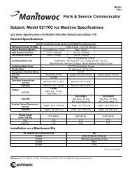
<strong>Manitowoc</strong><br />
S <strong>Model</strong><br />
<strong>Ice</strong> Machines<br />
<strong>Tech</strong>nician’s<br />
Handbook<br />
This manual is updated as new information and models<br />
are released. Visit our website for the latest manual.<br />
www.manitowocice.com<br />
America’s #1 Selling <strong>Ice</strong> Machine<br />
Part Number 80-1479-3 6/11
Safety Notices<br />
As you work on <strong>Manitowoc</strong> equipment, be sure to pay<br />
close attention to the safety notices in this handbook.<br />
Disregarding the notices may lead to serious injury<br />
and/or damage to the equipment.<br />
Throughout this handbook, you will see the following<br />
types of safety notices:<br />
! Warning<br />
Text in a Warning box alerts you to a potential<br />
personal injury situation. Be sure to read the<br />
Warning statement before proceeding, and work<br />
carefully.<br />
! Caution<br />
Text in a Caution box alerts you to a situation in<br />
which you could damage the equipment. Be sure<br />
to read the Caution statement before proceeding,<br />
and work carefully.<br />
Procedural Notices<br />
As you work on <strong>Manitowoc</strong> equipment, be sure to read<br />
the procedural notices in this handbook. These notices<br />
supply helpful information which may assist you as<br />
you work.<br />
Throughout this handbook, you will see the following<br />
types of procedural notices:<br />
Important<br />
Text in an Important box provides you with<br />
information that may help you perform a<br />
procedure more efficiently. Disregarding this<br />
information will not cause damage or injury, but it<br />
may slow you down as you work.
NOTE: Text set off as a Note provides you with simple,<br />
but useful, extra information about the procedure you<br />
are performing.<br />
Read These Before Proceeding:<br />
! Caution<br />
Proper installation, care and maintenance are<br />
essential for maximum performance and troublefree<br />
operation of your <strong>Manitowoc</strong> equipment. If<br />
you encounter problems not covered by this<br />
handbook, do not proceed, contact <strong>Manitowoc</strong><br />
Foodservice. We will be happy to provide<br />
assistance.<br />
Important<br />
Routine adjustments and maintenance<br />
procedures outlined in this handbook are not<br />
covered by the warranty.<br />
! Warning<br />
PERSONAL INJURY POTENTIAL<br />
Do not operate equipment that has been<br />
misused, abused, neglected, damaged, or<br />
altered/modified from that of original<br />
manufactured specifications.<br />
We reserve the right to make product<br />
improvements at any time. Specifications and<br />
design are subject to change without notice.
Table of Contents<br />
General Information<br />
<strong>Model</strong> Numbers . . . . . . . . . . . . . . . . . . . . . 9<br />
How to Read a <strong>Model</strong> Number . . . . . . 10<br />
<strong>Ice</strong> Cube Sizes . . . . . . . . . . . . . . . . . . . . . 10<br />
<strong>Model</strong>/Serial Number Location . . . . . . . . 11<br />
Energy Efficient <strong>Ice</strong> Machine<br />
Serial Breaks . . . . . . . . . . . . . . . . . . . . . . . 12<br />
<strong>Ice</strong> Machine Warranty Information . . . . . 13<br />
Owner Warranty Registration Card . . . 13<br />
Commercial Warranty Coverage . . . . . 14<br />
Residential <strong>Ice</strong> Machine Limited Warranty<br />
. . . . . . . . . . . . . . . . . . . . . . . . . . . . . . . 16<br />
Installation<br />
Location of <strong>Ice</strong> Machine . . . . . . . . . . . . . . 21<br />
<strong>Ice</strong> Machine Clearance Requirements . . 22<br />
<strong>Ice</strong> Machine Heat of Rejection . . . . . . . . . 23<br />
Remote Condenser Line Set Installation 24<br />
Calculating Remote Condenser<br />
Installation Distances . . . . . . . . . . . . . 25<br />
Lengthening or Reducing Line Set Lengths<br />
. . . . . . . . . . . . . . . . . . . . . . . . . . . . . . . 27<br />
Connecting A Line Set . . . . . . . . . . . . 28<br />
Component Identification<br />
S <strong>Model</strong> Single Evaporator <strong>Model</strong>s . . . . . 29<br />
S <strong>Model</strong> Quad Evaporator <strong>Model</strong>s . . . . . 30<br />
Maintenance<br />
General . . . . . . . . . . . . . . . . . . . . . . . . . . . 31<br />
Cleaning / Sanitizing Procedure . . . . . . . 32<br />
Cleaning Procedure . . . . . . . . . . . . . . 32<br />
Parts Removal for Cleaning/Sanitizing 34<br />
Procedure to Clean Heavily Scaled<br />
<strong>Ice</strong> Machines . . . . . . . . . . . . . . . . . . . . . . . 40<br />
General . . . . . . . . . . . . . . . . . . . . . . . . 40<br />
Cleaning Procedure . . . . . . . . . . . . . . 40<br />
Parts Removal for Cleaning/Sanitizing 43<br />
Part Number 80-1479-3 6/11 5
Removal from Service/Winterization . . . 57<br />
Self-Contained Air-Cooled <strong>Ice</strong> Machines 57<br />
Water-Cooled <strong>Ice</strong> Machines . . . . . . . . 58<br />
Remote <strong>Ice</strong> Machines . . . . . . . . . . . . . 58<br />
Sequence of Operation<br />
Self Contained Air or Water Cooled . . . . 59<br />
Single & Quad Evaporator <strong>Model</strong>s . . . 59<br />
Safety Timers . . . . . . . . . . . . . . . . . . . . . . 64<br />
Safety Limits . . . . . . . . . . . . . . . . . . . . . . 65<br />
Remotes . . . . . . . . . . . . . . . . . . . . . . . 72<br />
Troubleshooting<br />
Safety Limits . . . . . . . . . . . . . . . . . . . . . . 81<br />
Quad Evaporator Machines Only . . . . 82<br />
Analyzing Why a Safety Limit Stopped the<br />
<strong>Ice</strong> Machine . . . . . . . . . . . . . . . . . . . . 84<br />
Safety Limit #1 . . . . . . . . . . . . . . . . . . 85<br />
Safety Limit #2 . . . . . . . . . . . . . . . . . . 86<br />
Safety Limit #3 . . . . . . . . . . . . . . . . . . 87<br />
Control Board Testing . . . . . . . . . . . . . . . 88<br />
Control Board Test Cycle . . . . . . . . . . 88<br />
Troubleshooting By Symptom . . . . . . . . 89<br />
Symptom #1 <strong>Ice</strong> Machine will not run . 90<br />
Diagnosing an <strong>Ice</strong> Machine that Will Not Run<br />
. . . . . . . . . . . . . . . . . . . . . . . . . . . . . . 92<br />
Compressor Electrical Diagnostics . . . 93<br />
Symptom #2 Low Production, Long Freeze<br />
. . . . . . . . . . . . . . . . . . . . . . . . . . . . . . 95<br />
Symptom #2 - Freeze Cycle Refrigeration<br />
System Operational Analysis Tables . 97<br />
Freeze Cycle Refrigeration System Operational<br />
Analysis Table Procedures . . . . 106<br />
Harvest Problems . . . . . . . . . . . . . . . . . . 127<br />
Symptom #3 <strong>Ice</strong> Will Not Harvest, Cubes<br />
Are Not Melted . . . . . . . . . . . . . . . . . . 128<br />
Symptom #3 - Traditional Remotes Only<br />
. . . . . . . . . . . . . . . . . . . . . . . . . . . . . . 130<br />
Symptom #4 Will Not Harvest, Melted<br />
Cubes . . . . . . . . . . . . . . . . . . . . . . . . . 132<br />
6 Part Number 80-1479-3 6/11
Component Check Procedures<br />
Electrical Components . . . . . . . . . . . . . . . 135<br />
Main Fuse . . . . . . . . . . . . . . . . . . . . . . 135<br />
ICE/OFF/CLEAN Toggle Switch . . . . . 136<br />
Bin Switch . . . . . . . . . . . . . . . . . . . . . . 137<br />
Cleaning the <strong>Ice</strong> Thickness or Water Level<br />
Probe . . . . . . . . . . . . . . . . . . . . . . . . . . 140<br />
Water Level Control Circuitry . . . . . . . 141<br />
<strong>Ice</strong> Thickness Probe (Harvest Initiation)<br />
. . . . . . . . . . . . . . . . . . . . . . . . . . . . . . . 146<br />
Harvest Assist Air Pump . . . . . . . . . . . 151<br />
Compressor Electrical Diagnostics . . . . 152<br />
Diagnosing Start Components . . . . . . 154<br />
Refrigeration Components . . . . . . . . . . . 158<br />
High Pressure Cutout (HPCO) Control 158<br />
Fan Cycle Control . . . . . . . . . . . . . . . . 159<br />
Water Regulating Valve . . . . . . . . . . . 160<br />
Harvest Pressure Regulating (HPR) System<br />
Remotes Only . . . . . . . . . . . . . . . . . . . 161<br />
Head Pressure Control Valve . . . . . . . 164<br />
Low Pressure Cutout (LPCO) Control . 167<br />
Harvest Pressure Solenoid Valve . . . . 168<br />
Refrigerant Recovery/Evacuation . . . . . . 169<br />
Normal Self-Contained <strong>Model</strong> Procedures<br />
. . . . . . . . . . . . . . . . . . . . . . . . . . . . . . . 169<br />
Normal Remote <strong>Model</strong> Procedures . . . 173<br />
System Contamination Clean-Up . . . . . . 178<br />
Determining Severity Of Contamination 178<br />
Cleanup Procedure . . . . . . . . . . . . . . . 180<br />
Replacing Pressure Controls Without Removing<br />
Refrigerant Charge . . . . . . . . . 183<br />
Specifications<br />
Main Fuse . . . . . . . . . . . . . . . . . . . . . . 185<br />
Fan Cycle Control . . . . . . . . . . . . . . . . 185<br />
High Pressure Cutout (HPCO) Control 185<br />
Filter-Driers . . . . . . . . . . . . . . . . . . . . . 186<br />
Total System Refrigerant Charge . . . . 187<br />
Part Number 80-1479-3 6/11 7
Charts<br />
Cycle Times/24-Hour <strong>Ice</strong> Production/<br />
Refrigerant Pressure Charts . . . . . . . . . . 191<br />
S300 Series . . . . . . . . . . . . . . . . . . . . 192<br />
S320 Series . . . . . . . . . . . . . . . . . . . . 196<br />
S420 Series . . . . . . . . . . . . . . . . . . . . 198<br />
S450 Series . . . . . . . . . . . . . . . . . . . . 202<br />
S500 Series . . . . . . . . . . . . . . . . . . . . 206<br />
S600 Series . . . . . . . . . . . . . . . . . . . . 215<br />
S850 Series . . . . . . . . . . . . . . . . . . . . 218<br />
S1000 Series . . . . . . . . . . . . . . . . . . . 227<br />
S1200 Series . . . . . . . . . . . . . . . . . . . 236<br />
S1400 Series . . . . . . . . . . . . . . . . . . . 242<br />
S1600 Series . . . . . . . . . . . . . . . . . . . 253<br />
S1800 Series . . . . . . . . . . . . . . . . . . . 256<br />
S3300 Series . . . . . . . . . . . . . . . . . . . 265<br />
Diagrams<br />
Wiring Diagrams . . . . . . . . . . . . . . . . . . . 267<br />
Wiring Diagram Legend . . . . . . . . . . . 267<br />
Wiring Diagrams Before Energy Efficient &<br />
EnergyStar Machines . . . . . . . . . . . . . 268<br />
Wiring Diagrams for Energy Efficient & EnergyStar<br />
Machines . . . . . . . . . . . . . . . 279<br />
Electronic Control Board . . . . . . . . . . . . 290<br />
Single and Twin Evaporator Without Test<br />
Button . . . . . . . . . . . . . . . . . . . . . . . . . 290<br />
Single and Twin Evaporator With Test Button<br />
. . . . . . . . . . . . . . . . . . . . . . . . . . . 291<br />
Quad Evaporator <strong>Ice</strong> Machines . . . . . 292<br />
Refrigeration Tubing Schematics . . . . . 293<br />
Self-Contained Air- or<br />
Water -Cooled <strong>Model</strong>s . . . . . . . . . . . . 293<br />
Remote <strong>Model</strong>s . . . . . . . . . . . . . . . . . 295<br />
8 Part Number 80-1479-3 6/11
General Information<br />
<strong>Model</strong> Numbers<br />
This manual covers the following models:<br />
Self-Contained<br />
Air-Cooled<br />
SD0302A<br />
SY0304A<br />
SD0322A<br />
SY0324A<br />
SR0420A<br />
SD0422A<br />
SY0424A<br />
SD0452A<br />
SY0454A<br />
SR0500A<br />
SD0502A<br />
SY0504A<br />
SD0602A<br />
SY0604A<br />
SR0850A<br />
SD0852A<br />
SY0854A<br />
SR1000A<br />
SD1002A<br />
SY1004A<br />
SD1202A<br />
SY1204A<br />
SD1402A<br />
SY1404A<br />
SR1600A<br />
SD1602A<br />
SY1604A<br />
SR1800A<br />
SD1802A<br />
SY1804A<br />
---<br />
---<br />
---<br />
---<br />
Self-Contained<br />
Water-Cooled<br />
SD0303W<br />
SY0305W<br />
SD0323W<br />
SY0325W<br />
SR0421W<br />
SD0423W<br />
SY0425W<br />
SD0453W<br />
SY0455W<br />
SR0501W<br />
SD0503W<br />
SY0505W<br />
SD0603W<br />
SY0605W<br />
SR0851W<br />
SD0853W<br />
SY0855W<br />
SR1001W<br />
SD1003W<br />
SY1005W<br />
SD1203W<br />
SY1205W<br />
SD1403W<br />
SY1405W<br />
SR1601W<br />
SD1603W<br />
SY1605W<br />
SR1801W<br />
SD1803W<br />
SY1805W<br />
SD3303W<br />
SD3303WHP<br />
SY3305W<br />
SY3305WHP<br />
Remote<br />
NOTE: <strong>Model</strong> numbers ending in 3 indicate a 3<br />
phase unit. Example: SY1004A3.<br />
Part Number 80-1479-3 6/11 9<br />
---<br />
---<br />
---<br />
---<br />
---<br />
---<br />
---<br />
---<br />
SD0592N<br />
SY0594N<br />
SD0692N<br />
SY0694N<br />
SR0890N<br />
SD0892N<br />
SY0894N<br />
SR1090N<br />
SD1092N<br />
SY1094N<br />
---<br />
---<br />
SD1492N<br />
SY1494N<br />
SR1690N<br />
SD1692N<br />
SY1694N<br />
SR1890N<br />
SD1892N<br />
SY1894N<br />
---<br />
---<br />
---<br />
---
HOW TO READ A MODEL NUMBER<br />
9 REMOTE<br />
AIR-COOLED<br />
ICE MACHINE<br />
MODEL<br />
ICE CUBE SIZE<br />
R REGULAR<br />
D DICE<br />
Y HALF DICE<br />
<strong>Ice</strong> Cube Sizes<br />
Regular<br />
1-1/8" x 1-1/8" x 7/8"<br />
2.86 x 2.86 x 2.22 cm<br />
# CUBE SIZE CONDENSER TYPE<br />
0<br />
1<br />
2<br />
3<br />
4<br />
5<br />
REGULAR<br />
REGULAR<br />
DICE<br />
DICE<br />
HALF-DICE<br />
HALF-DICE<br />
AIR-COOLED<br />
WATER-COOLED<br />
AIR-COOLED<br />
WATER-COOLED<br />
AIR-COOLED<br />
WATER-COOLED<br />
S Y 1094 N SI<br />
ICE MACHINE<br />
SERIES<br />
CONDENSER TYPE<br />
A SELF-CONTAINED AIR-COOLED<br />
W SELF-CONTAINED WATER-COOLED<br />
N REMOTE AIR-COOLED<br />
Dice<br />
7/8" x 7/8" x 7/8"<br />
2.22 x 2.22 x2.22 cm<br />
ADDITIONAL SPECS<br />
3 PHASE<br />
M MARINE UNIT<br />
HP HIGH PRESSURE<br />
WATER VALVE<br />
SI AUCS-SI INCLUDED<br />
Half Dice<br />
3/8" x 1-1/8" x 7/8"<br />
0.95 x 2.86 x 2.22 cm<br />
! Warning<br />
Personal Injury Potential<br />
Do not operate equipment that has been misused,<br />
abused, neglected, damaged, or altered/modified<br />
from that of original manufactured specifications.<br />
10 Part Number 80-1479-3 6/11
! Warning<br />
All <strong>Manitowoc</strong> ice machines require the ice<br />
storage system (bin, dispenser, etc.) to<br />
incorporate an ice deflector.<br />
48” wide S <strong>Model</strong> ice machines require adding<br />
<strong>Manitowoc</strong> <strong>Ice</strong> Deflector Kit K00349 when<br />
installing with non-<strong>Manitowoc</strong> ice storage<br />
systems.<br />
30” wide S <strong>Model</strong> ice machines require adding<br />
<strong>Manitowoc</strong> <strong>Ice</strong> Deflector Kit K00347 when<br />
installing with non-<strong>Manitowoc</strong> ice storage<br />
systems.<br />
Prior to using a non-<strong>Manitowoc</strong> ice storage<br />
system with other <strong>Manitowoc</strong> ice machines,<br />
contact the manufacturer to assure their ice<br />
deflector is compatible with <strong>Manitowoc</strong> ice<br />
machines.<br />
<strong>Model</strong>/Serial Number Location<br />
These numbers are required when requesting<br />
information from your local <strong>Manitowoc</strong> Distributor,<br />
service representative, or <strong>Manitowoc</strong> <strong>Ice</strong>, Inc. The<br />
model and serial number are listed on the OWNER<br />
WARRANTY REGISTRATION CARD. They are also<br />
listed on the MODEL/SERIAL NUMBER DECAL<br />
affixed to the ice machine.<br />
Part Number 80-1479-3 6/11 11
Energy Efficient <strong>Ice</strong> Machine<br />
Serial Breaks<br />
Some specifications have changed with our release of<br />
more Energy Efficient machines. The following<br />
machines have a serial break to indicate when they<br />
became more Energy Efficient.<br />
Series <strong>Ice</strong><br />
Machine<br />
Serial Break/Manufacture Date for<br />
Energy Efficient Machines<br />
S300 110704351<br />
S420 110667970<br />
S450 110670157<br />
S500 110684316<br />
S850 110683282<br />
S1000 110697023<br />
S1200 110707329<br />
S1400W<br />
S1400W<br />
S1400A<br />
S1400W<br />
S1400N<br />
S1800A<br />
S1800W<br />
S1800N<br />
Manufacture Date After 0711<br />
(November 2007)<br />
Manufacture Date Between<br />
0711 & 0905<br />
(November 2007 & May 2009)<br />
Manufacture Date After 0905<br />
(May 2009)<br />
Manufacture Date After 0910<br />
(October 2009)<br />
12 Part Number 80-1479-3 6/11
<strong>Ice</strong> Machine Warranty Information<br />
OWNER WARRANTY REGISTRATION CARD<br />
Warranty coverage begins the day the ice machine is<br />
installed.<br />
Important<br />
Complete and mail the OWNER WARRANTY<br />
REGISTRATION CARD as soon as possible to<br />
validate the installation date.<br />
If the OWNER WARRANTY REGISTRATION CARD is<br />
not returned, <strong>Manitowoc</strong> will use the date of sale to the<br />
<strong>Manitowoc</strong> Distributor as the first day of warranty<br />
coverage for your new ice machine.<br />
Part Number 80-1479-3 6/11 13
COMMERCIAL WARRANTY COVERAGE<br />
<strong>Manitowoc</strong> <strong>Ice</strong>, (hereinafter referred to as the<br />
"COMPANY") warrants for a period of thirty-six months<br />
from the installation date (except as limited below) that<br />
new ice machines manufactured by the COMPANY<br />
shall be free of defects in material or workmanship<br />
under normal and proper use and maintenance as<br />
specified by the COMPANY and upon proper<br />
installation and start-up in accordance with the<br />
instruction manual supplied with the ice machine.<br />
The COMPANY'S warranty hereunder with respect to<br />
the compressor shall apply for an additional twentyfour<br />
months, excluding all labor charges, and with<br />
respect to the evaporator for an additional twenty-four<br />
months, including labor charges.<br />
The obligation of the COMPANY under this warranty is<br />
limited to the repair or replacement of parts,<br />
components, or assemblies that in the opinion of the<br />
COMPANY are defective. This warranty is further<br />
limited to the cost of parts, components or assemblies<br />
and standard straight time labor charges at the<br />
servicing location. Time and hourly rate schedules, as<br />
published from time to time by the COMPANY, apply to<br />
all service procedures.<br />
Additional expenses including without limitation, travel<br />
time, overtime premium, material cost, accessing or<br />
removal of the ice machine, or shipping are the<br />
responsibility of the owner, along with all maintenance,<br />
adjustments, cleaning, and ice purchases.<br />
Labor covered under this warranty must be performed<br />
by a COMPANY Contracted Service Representative or<br />
a refrigeration service agency as qualified and<br />
authorized by the COMPANY'S local Distributor.<br />
The COMPANY'S liability under this warranty shall in<br />
no event be greater than the actual purchase price<br />
paid by customer for the ice machine.<br />
14 Part Number 80-1479-3 6/11
The foregoing warranty shall not apply to (1) any part<br />
or assembly that has been altered, modified, or<br />
changed; (2) any part or assembly that has been<br />
subjected to misuse, abuse, neglect, or accidents; (3)<br />
any ice machine that has been installed and/or<br />
maintained inconsistent with the technical instructions<br />
provided by the COMPANY; or (4) any ice machine<br />
initially installed more than five years from the serial<br />
number production date. This warranty shall not apply<br />
if the <strong>Ice</strong> Machine's refrigeration system is modified<br />
with a condenser, heat reclaim device, or parts and<br />
assemblies other than those manufactured by the<br />
COMPANY, unless the COMPANY approves these<br />
modifications for specific locations in writing.<br />
THIS WARRANTY IS IN LIEU OF ALL OTHER<br />
WARRANTIES OR GUARANTEES OF ANY<br />
KIND, EXPRESSED OR IMPLIED, INCLUDING ANY<br />
IMPLIED WARRANTY OF MERCHANTABILITY<br />
OR FITNESS FOR A PARTICULAR PURPOSE.<br />
In no event shall the COMPANY be liable for any<br />
special, indirect, incidental or consequential damages.<br />
Upon the expiration of the warranty period, the<br />
COMPANY'S liability under this warranty shall<br />
terminate. The foregoing warranty shall constitute the<br />
sole liability of the COMPANY and the exclusive<br />
remedy of the customer or user.<br />
To secure prompt and continuing warranty service, the<br />
warranty registration card must be completed and sent<br />
to the COMPANY within five (5) days from the<br />
installation date.<br />
To obtain warranty service or information regarding<br />
your Product, please contact us at:<br />
MANITOWOC ICE<br />
2110 So. 26th St. P.O. Box 1720,<br />
<strong>Manitowoc</strong>, WI 54221-1720<br />
Telephone: 920-682-0161 Fax: 920-683-7585<br />
www.manitowocice.com<br />
Part Number 80-1479-3 6/11 15
RESIDENTIAL ICE MACHINE LIMITED WARRANTY<br />
WHAT DOES THIS LIMITED WARRANTY COVER?<br />
Subject to the exclusions and limitations below,<br />
<strong>Manitowoc</strong> <strong>Ice</strong>, Inc. (“<strong>Manitowoc</strong>”) warrants to the<br />
original consumer that any new ice machine<br />
manufactured by <strong>Manitowoc</strong> (the “Product”) shall be<br />
free of defects in material or workmanship for the<br />
warranty period outlined below under normal use and<br />
maintenance, and upon proper installation and startup<br />
in accordance with the instruction manual supplied<br />
with the Product.<br />
HOW LONG DOES THIS LIMITED WARRANTY<br />
LAST?<br />
Product Covered Warranty Period<br />
<strong>Ice</strong> Machine<br />
Twelve months from the<br />
sale date<br />
WHO IS COVERED BY THIS LIMITED WARRANTY?<br />
This limited warranty only applies to the original<br />
consumer of the Product and is not transferable.<br />
16 Part Number 80-1479-3 6/11
WHAT ARE MANITOWOC ICE’S OBLIGATIONS<br />
UNDER THIS LIMITED WARRANTY?<br />
If a defect arises and <strong>Manitowoc</strong> receives a valid<br />
warranty claim prior to the expiration of the warranty<br />
period, <strong>Manitowoc</strong> shall, at its option: (1) repair the<br />
Product at <strong>Manitowoc</strong>’s cost, including standard<br />
straight time labor charges, (2) replace the Product<br />
with one that is new or at least as functionally<br />
equivalent as the original, or (3) refund the purchase<br />
price for the Product. Replacement parts are<br />
warranted for 90 days or the balance of the original<br />
warranty period, whichever is longer. The foregoing<br />
constitutes <strong>Manitowoc</strong>’s sole obligation and the<br />
consumer’s exclusive remedy for any breach of this<br />
limited warranty. <strong>Manitowoc</strong>’s liability under this limited<br />
warranty is limited to the purchase price of Product.<br />
Additional expenses including, without limitation,<br />
service travel time, overtime or premium labor<br />
charges, accessing or removing the Product, or<br />
shipping are the responsibility of the consumer.<br />
HOW TO OBTAIN WARRANTY SERVICE<br />
To obtain warranty service or information regarding<br />
your Product, please contact us at:<br />
MANITOWOC ICE<br />
2110 So. 26th St.<br />
P.O. Box 1720,<br />
<strong>Manitowoc</strong>, WI 54221-1720<br />
Telephone: 920-682-0161 Fax: 920-683-7585<br />
www.manitowocice.com<br />
Part Number 80-1479-3 6/11 17
WHAT IS NOT COVERED?<br />
This limited warranty does not cover, and you are<br />
solely responsible for the costs of: (1) periodic or<br />
routine maintenance, (2) repair or replacement of the<br />
Product or parts due to normal wear and tear, (3)<br />
defects or damage to the Product or parts resulting<br />
from misuse, abuse, neglect, or accidents, (4) defects<br />
or damage to the Product or parts resulting from<br />
improper or unauthorized alterations, modifications, or<br />
changes; and (5) defects or damage to any Product<br />
that has not been installed and/or maintained in<br />
accordance with the instruction manual or technical<br />
instructions provided by <strong>Manitowoc</strong>. To the extent that<br />
warranty exclusions are not permitted under some<br />
state laws, these exclusions may not apply to you.<br />
EXCEPT AS STATED IN THE FOLLOWING SENTENCE, THIS<br />
LIMITED WARRANTY IS THE SOLE AND EXCLUSIVE<br />
WARRANTY OF MANITOWOC WITH REGARD TO THE<br />
PRODUCT. ALL IMPLIED WARRANTIES ARE STRICTLY<br />
LIMITED TO THE DURATION OF THE LIMITED WARRANTY<br />
APPLICABLE TO THE PRODUCTS AS STATED ABOVE,<br />
INCLUDING BUT NOT LIMITED TO, ANY WARRANTY OF<br />
MERCHANTABILITY OR OF FITNESS FOR A PARTICULAR<br />
PURPOSE.<br />
Some states do not allow limitations on how long an<br />
implied warranty lasts, so the above limitation may not<br />
apply to you.<br />
18 Part Number 80-1479-3 6/11
IN NO EVENT SHALL MANITOWOC OR ANY OF ITS<br />
AFFILIATES BE LIABLE TO THE CONSUMER OR ANY<br />
OTHER PERSON FOR ANY INCIDENTAL, CONSEQUENTIAL<br />
OR SPECIAL DAMAGES OF ANY KIND (INCLUDING,<br />
WITHOUT LIMITATION, LOSS OF PROFITS, REVENUE OR<br />
BUSINESS) ARISING FROM OR IN ANY MANNER<br />
CONNECTED WITH THE PRODUCT, ANY BREACH OF THIS<br />
LIMITED WARRANTY, OR ANY OTHER CAUSE<br />
WHATSOEVER, WHETHER BASED ON CONTRACT, TORT<br />
OR ANY OTHER THEORY OF LIABILITY.<br />
Some states do not allow the exclusion or limitation of<br />
incidental or consequential damages, so the above<br />
limitation or exclusion may not apply to you.<br />
HOW STATE LAW APPLIES<br />
This limited warranty gives you specific legal rights,<br />
and you may also have rights that vary from state to<br />
state or from one jurisdiction to another.<br />
REGISTRATION CARD<br />
To secure prompt and continuing warranty service, this<br />
warranty registration card must be completed and sent<br />
to <strong>Manitowoc</strong> within thirty (30) days from the sale date.<br />
Complete the registration card and send it to<br />
<strong>Manitowoc</strong>.<br />
Part Number 80-1479-3 6/11 19
This Page Intentionally Left Blank<br />
20 Part Number 80-1479-3 6/11
Installation<br />
! Warning<br />
PERSONAL INJURY POTENTIAL<br />
Remove all ice machine panels before lifting and<br />
installing.<br />
Location of <strong>Ice</strong> Machine<br />
The location selected for the ice machine head section<br />
must meet the following criteria. If any of these criteria<br />
are not met, select another location.<br />
• The location must be free of airborne and other<br />
contaminants.<br />
• Self contained air and water cooled - The air<br />
temperature must be at least 35°F (1.6°C), but<br />
must not exceed 110°F (43.4°C).<br />
• Remote air cooled - The air temperature must be<br />
at least -20°F (-29°C), but must not exceed 120°F<br />
(49°C)<br />
• <strong>Ice</strong> Making Water Inlet - Water Pressure must be<br />
at least 20 psi (1.38 bar), but must not exceed 80<br />
psi (5.52 bar).<br />
• Condenser Water Inlet - Water Pressure must be<br />
at least 20 psi (1.38 bar), but must not exceed<br />
150 psi (10.34 bar). S3300W-HP units allow water<br />
pressure up to 350 psig (24.13 bar).<br />
• The location must not be near heat-generating<br />
equipment or in direct sunlight and protected from<br />
weather.<br />
• The location must not obstruct air flow through or<br />
around the ice machine. Refer to chart below for<br />
clearance requirements.<br />
• The ice machine must be protected if it will be<br />
subjected to temperatures below 32°F (0°C).<br />
Failure caused by exposure to freezing<br />
temperatures is not covered by the warranty. See<br />
“Removal from Service/Winterization”<br />
Part Number 80-1479-3 6/11 21
<strong>Ice</strong> Machine Clearance Requirements<br />
S300<br />
Self-Contained<br />
Air-Cooled<br />
Self-Contained<br />
Water-Cooled<br />
Top/Sides 16" (40.6 cm) 8" (20.3 cm)<br />
Back 5" (12.7 cm) 5" (12.7 cm)<br />
S320/S450/S500/<br />
S600/S850/S1000<br />
Self-Contained<br />
Air-Cooled<br />
Water-Cooled and<br />
Remote*<br />
Top/Sides 8" (20.3 cm) 8" (20.3 cm)<br />
Back 5" (12.7 cm) 5" (12.7 cm)<br />
S420<br />
Self-Contained<br />
Air-Cooled<br />
Water-Cooled and<br />
Remote*<br />
Top/Sides 12" (30.5 cm) 8" (20.3 cm)<br />
Back 5" (12.7 cm) 5" (12.7 cm)<br />
S1200<br />
Self-Contained<br />
Air-Cooled<br />
Water-Cooled and<br />
Remote*<br />
Top 8" (20.3 cm) 8" (20.3 cm)<br />
Sides 12" (30.5 cm) 8" (20.3 cm)<br />
Back 5" (12.7 cm) 5" (12.7 cm)<br />
S1400/S1600/<br />
S1800<br />
Self-Contained<br />
Air-Cooled<br />
Water-Cooled<br />
and Remote*<br />
Top/Sides 24" (61.0 cm) 8" (20.3 cm)<br />
Back 12" (30.5 cm) 5" (12.7 cm) *<br />
S3300 **<br />
Water-Cooled<br />
Top/Sides 8" (20.3 cm)<br />
Back 24" (61.0 cm)<br />
* There is no minimum clearance required for water-cooled or<br />
remote ice machines. This value is recommended for efficient<br />
operation and servicing only.<br />
** S3300 - 24” on all sides is recommended to allow access without<br />
moving the bin/ice machine.<br />
22 Part Number 80-1479-3 6/11
<strong>Ice</strong> Machine Heat of Rejection<br />
Heat of Rejection<br />
Series <strong>Ice</strong><br />
Machine<br />
Air<br />
Conditioning*<br />
Peak<br />
S300 3,800 6,000<br />
S320 3,800 6,000<br />
S420/S450 7,000 9,600<br />
S500 7,000 9,600<br />
S600 9,000 13,900<br />
S850 12,000 18,000<br />
S1000 16,000 22,000<br />
S1200 19,000 28,000<br />
S1400 19,000 28,000<br />
S1600 21,000 31,000<br />
S1800 24,000<br />
Energy Efficient Machines<br />
36,000<br />
S300 5,000 6,000<br />
S420/S450 5,900 6,900<br />
S500 6,100 6,900<br />
S850 13,000 16,000<br />
S1000 17,700 21,000<br />
S1200 20,700 24,500<br />
S1400W 25,000 28,000<br />
S1400A/<br />
S1400N<br />
23,500 27,000<br />
S1800 31,000 36,000<br />
S3300 45,000 51,000<br />
*BTU/Hour<br />
Because the heat of rejection varies during the ice making<br />
cycle, the figure shown is an average.<br />
Part Number 80-1479-3 6/11 23
REMOTE CONDENSER LINE SET INSTALLATION<br />
<strong>Ice</strong> Machine<br />
Remote Single<br />
Circuit<br />
Condenser<br />
S500 JC0495<br />
S600<br />
S800<br />
S1000<br />
S1400<br />
S1600<br />
S1800<br />
JC0895<br />
JC1395<br />
Line Set*<br />
RT-20-R404A<br />
RT-35-R404A<br />
RT-50-R404A<br />
RT-20-R404A<br />
RT-35-R404A<br />
RT-50-R404A<br />
RL-20-R404A<br />
RL-35-R404A<br />
RL-50-R404A<br />
*Line Set Discharge Line Liquid Line<br />
RT 1/2" (1.27 cm) 5/16" (.79 cm)<br />
RL 1/2" (1.27 cm) 3/8" (.95 cm)<br />
Air Temperature Around the Condenser<br />
Minimum Maximum<br />
-20°F (-29°C) 120°F (49°C)<br />
Important<br />
<strong>Manitowoc</strong> remote systems are only approved<br />
and warranted as a complete new package.<br />
Warranty on the refrigeration system will be<br />
void if a new ice machine head section is<br />
connected to pre-existing (used) tubing or<br />
remote condensers or vice versa.<br />
24 Part Number 80-1479-3 6/11
CALCULATING REMOTE CONDENSER<br />
INSTALLATION DISTANCES<br />
NOTE: <strong>Manitowoc</strong> warrants only complete new and<br />
unused remote packages. Warranty on the<br />
refrigeration system will be void if a new ice machine<br />
head section is connected to existing (used) tubing or<br />
condensers.<br />
Line Set Length<br />
The maximum length is 100' (30.5 m).<br />
The ice machine compressor must have the proper oil<br />
return. The receiver is designed to hold a charge<br />
sufficient to operate the ice machine in ambient<br />
temperatures between -20°F (-28.9°C) and 120°F<br />
(49°C), with line set lengths of up to 100' (30.5 m).<br />
Line Set Rise/Drop<br />
The maximum rise is 35' (10.7 m).<br />
The maximum drop is 15' (4.5 m).<br />
! Caution<br />
If a line set has a rise followed by a drop, another<br />
rise cannot be made. Likewise, if a line set has a<br />
drop followed by a rise, another drop cannot be<br />
made.<br />
Part Number 80-1479-3 6/11 25
Calculated Line Set Distance<br />
The maximum calculated distance is 150' (45.7 m).<br />
Line set rises, drops, horizontal runs (or combinations<br />
of these) in excess of the stated maximums will<br />
exceed compressor start-up and design limits. This will<br />
cause poor oil return to the compressor.<br />
Make the following calculations to make sure the line<br />
set layout is within specifications.<br />
1. Insert the measured rise into the formula below.<br />
Multiply by 1.7 to get the calculated rise.<br />
(Example: A condenser located 10 feet above the<br />
ice machine has a calculated rise of 17 feet.)<br />
2. Insert the measured drop into the formula below.<br />
Multiply by 6.6 to get the calculated drop.<br />
(Example. A condenser located 10 feet below the<br />
ice machine has a calculated drop of 66 feet.)<br />
3. Insert the measured horizontal distance into the<br />
formula below. No calculation is necessary.<br />
4. Add together the calculated rise, calculated<br />
drop, and horizontal distance to get the total<br />
calculated distance. If this total exceeds 150'<br />
(45.7 m), move the condenser to a new location<br />
and perform the calculations again.<br />
26 Part Number 80-1479-3 6/11
Maximum Line Set Distance Formula<br />
Step 1<br />
Measured Rise ____ X 1.7 = ______Calculated Rise<br />
(35 ft. Max)<br />
Step 2<br />
Measured Drop ____ X 6.6 = ______Calculated Drop<br />
(15 ft. Max.)<br />
Step 3<br />
Measured Horizontal Distance = _________Horizontal<br />
(100 ft. Max.) Distance<br />
Step 4<br />
Total Calculated Distance = ________Total Calculated<br />
(150 ft. Max.) Distance<br />
LENGTHENING OR REDUCING LINE SET<br />
LENGTHS<br />
In most cases, by routing the line set properly,<br />
shortening will not be necessary. When shortening or<br />
lengthening is required, do so before connecting the<br />
line set to the ice machine or the remote condenser.<br />
This prevents the loss of refrigerant in the ice machine<br />
or condenser.<br />
The quick connect fittings on the line sets are<br />
equipped with Schraeder valves. Use these valves to<br />
recover any vapor charge from the line set. When<br />
lengthening or shortening lines follow good<br />
refrigeration practices, purge with nitrogen and<br />
insulate all tubing. Do not change the tube sizes.<br />
Evacuate the lines and place about 5 oz (143g) of<br />
vapor refrigerant charge in each line.<br />
Part Number 80-1479-3 6/11 27
CONNECTING A LINE SET<br />
1. Remove the dust caps from the line set,<br />
condenser and ice machine.<br />
2. Apply refrigeration oil to the threads on the quick<br />
disconnect couplers before connecting them to<br />
the condenser.<br />
3. Carefully thread the female fitting to the<br />
condenser or ice machine by hand.<br />
4. Tighten the couplings with a wrench until they<br />
bottom out.<br />
5. Turn an additional 1/4 turn to ensure proper<br />
brass-to-brass seating. Torque to the following<br />
specifications:<br />
Liquid Line Discharge Line<br />
10-12 ft lb.<br />
(13.5-16.2 N•m)<br />
35-45 ft lb.<br />
(47.5-61.0 N•m)<br />
6. Check all fittings and valve caps for leaks.<br />
7. Make sure Schraeder cores are seated and<br />
Schraeder caps are on and tight.<br />
28 Part Number 80-1479-3 6/11
Component Identification<br />
S <strong>Model</strong> Single Evaporator <strong>Model</strong>s<br />
WATER<br />
DISTRIBUTION<br />
TUBE<br />
WATER<br />
TROUGH<br />
WATER LEVEL<br />
PROBE<br />
ICE<br />
THICKNESS<br />
CONTROL<br />
EVAPORATOR<br />
REFRIGERATION<br />
ACCESS VALVES<br />
TOGGLE<br />
SWITCH<br />
WATER CURTAIN CONTROL BOX<br />
WATER PUMP<br />
WATER INLET<br />
LOCATION, THE<br />
WATER INLET VALVE<br />
IS LOCATED IN THE<br />
REFRIGERATION<br />
COMPARTMENT<br />
Part Number 80-1479-3 6/11 29
S <strong>Model</strong> Quad Evaporator <strong>Model</strong>s<br />
CONTROL<br />
BOX<br />
EVAPORATORS<br />
WATER<br />
PUMPS<br />
WATER LEVEL<br />
PROBE<br />
WATER<br />
TROUGH<br />
30 Part Number 80-1479-3 6/11<br />
ICE DAMPERS
Maintenance<br />
General<br />
Clean and sanitize the ice machine every six months<br />
for efficient operation. If the ice machine requires more<br />
frequent cleaning and sanitizing, consult a water care<br />
professional to test the water quality and recommend<br />
appropriate water treatment. An extremely dirty ice<br />
machine must be taken apart for cleaning and<br />
sanitizing.<br />
<strong>Manitowoc</strong> <strong>Ice</strong> Machine Cleaner and Sanitizer are the<br />
only products approved for use in <strong>Manitowoc</strong> ice<br />
machines.<br />
This <strong>Manitowoc</strong> <strong>Ice</strong> Machine has two separate<br />
cleaning procedures.<br />
Cleaning/Sanitizing Procedure<br />
This procedure must be performed a minimum of once<br />
every six months.<br />
• The ice machine and bin must be disassembled<br />
cleaned and sanitized<br />
• All ice produced during the cleaning and sanitizing<br />
procedures must be discarded<br />
• Removes mineral deposits from areas or surfaces<br />
that are in direct contact with water<br />
Heavily Scaled Cleaning Procedure<br />
Perform this procedure if you have some or all of these<br />
symptoms.<br />
• <strong>Ice</strong> machine stops on Safety Shutdown<br />
• Your water has a high concentration of minerals<br />
• The ice machine has not been on a regular<br />
maintenance schedule.<br />
Part Number 80-1479-3 6/11 31
Cleaning / Sanitizing Procedure<br />
! Caution<br />
Use only <strong>Manitowoc</strong> approved <strong>Ice</strong> Machine<br />
Cleaner and Sanitizer for this application<br />
(<strong>Manitowoc</strong> Cleaner part number 94-0546-3 and<br />
<strong>Manitowoc</strong> Sanitizer part number 94-0565-3). It is<br />
a violation of Federal law to use these solutions in<br />
a manner inconsistent with their labeling. Read<br />
and understand all labels printed on bottles<br />
before use.<br />
CLEANING PROCEDURE<br />
! Caution<br />
Do not mix Cleaner and Sanitizer solutions<br />
together. It is a violation of Federal law to use<br />
these solutions in a manner inconsistent with their<br />
labeling.<br />
! Warning<br />
Wear rubber gloves and safety goggles (and/or<br />
face shield) when handling ice machine Cleaner<br />
or Sanitizer.<br />
<strong>Ice</strong> machine cleaner is used to remove lime scale and<br />
mineral deposits. <strong>Ice</strong> machine sanitizer disinfects and<br />
removes algae and slime.<br />
Step 1 Remove front door and top cover. This will<br />
allow easiest access for adding cleaning and<br />
sanitizing solutions.<br />
Step 2 Set the toggle switch to the OFF position after<br />
ice falls from the evaporator at the end of a Harvest<br />
cycle. Or, set the switch to the OFF position and allow<br />
the ice to melt off the evaporator.<br />
! Caution<br />
Never use anything to force ice from the<br />
evaporator. Damage may result.<br />
32 Part Number 80-1479-3 6/11
Step 3 Remove all ice from the bin.<br />
Step 4 Place the toggle switch in the CLEAN<br />
position. The water will flow through the water dump<br />
valve and down the drain. Wait until the water trough<br />
refills and water flows over the evaporator, then add<br />
the proper amount of ice machine cleaner.<br />
<strong>Model</strong> Amount of Cleaner<br />
S300/S320/S420 3 ounces (90 ml)<br />
S450/S500/S600/S850/<br />
5 ounces (150 ml)<br />
S1000/S1200<br />
S1400/S1600/S1800 9 ounces (265 ml)<br />
S3300 16 ounces (475 ml)<br />
Step 5 Wait until the clean cycle is complete<br />
(approximately *35 minutes). then place the toggle<br />
switch in the OFF position and disconnect power to<br />
the ice machine (and dispenser when used).<br />
NOTE: *S3300 Only - 80 minutes..<br />
! Warning<br />
Disconnect the electric power to the ice machine<br />
at the electric service switch box.<br />
Step 6 Remove parts for cleaning.<br />
Please refer to the proper parts removal for your<br />
ice machine.<br />
Single Evaporator <strong>Ice</strong> Machines - page 34.<br />
Quad Evaporator <strong>Ice</strong> Machines - page 35.<br />
Part Number 80-1479-3 6/11 33
PARTS REMOVAL FOR CLEANING/SANITIZING<br />
Single Evaporator <strong>Ice</strong> Machines<br />
A. Remove the water curtain<br />
• Gently flex the curtain in the center and remove it<br />
from the right side.<br />
• Slide the left pin out.<br />
B. Remove the ice thickness probe<br />
• Compress the hinge pin on the top of the ice<br />
thickness probe.<br />
• Pivot the ice thickness probe to disengage one pin<br />
then the other. The ice thickness probe can be<br />
cleaned at this point without complete removal. If<br />
complete removal is desired, disconnect the ice<br />
thickness control wiring from the control board.<br />
C. Remove the water trough<br />
• Depress tabs on right and left side of the water<br />
trough.<br />
• Allow front of water trough to drop as you pull<br />
forward to disengage the rear pins.<br />
NOTE: Proceed to page 37, Step 7.<br />
A.<br />
C.<br />
34 Part Number 80-1479-3 6/11<br />
B.
Quad Evaporator <strong>Ice</strong> Machines<br />
A.Remove the water trough shield.<br />
• Grasp the water trough shield in the center and the<br />
left end.<br />
• Flex the water trough shield in the center and pull<br />
the left end forward until clear of the side wall.<br />
Repeat for the right end.<br />
• Pull water trough shield forward to remove.<br />
B. Remove Splash Shields.<br />
• Grasp the top center of splash shields.<br />
• Lift up and then out.<br />
C. Remove ice thickness probe.<br />
• Compress the hinge pin on the top of the ice<br />
thickness probe.<br />
• Pivot the ice thickness probe to disengage one pin<br />
then the other. The ice thickness probe can be<br />
cleaned at this point without complete removal. If<br />
complete removal is desired, disconnect the ice<br />
thickness control wiring from the control board.<br />
D. Remove the water pump assembly<br />
• Disconnect the vinyl distribution tube from both<br />
water pumps.<br />
• Disconnect the water pump and water level probe<br />
electrical connections.<br />
• Remove two thumbscrews and lift the water pump<br />
assembly out of the ice machine.<br />
E. Remove the water trough.<br />
• Depress the two tabs on the top of the water<br />
trough.<br />
• Turn left and right ice dampers down to clear water<br />
trough.<br />
• Pull forward on the water trough to remove.<br />
NOTE: Proceed to page 37, Step 7.<br />
Continued on next page …<br />
Part Number 80-1479-3 6/11 35
D<br />
C<br />
E<br />
36 Part Number 80-1479-3 6/11<br />
B<br />
A
Step 7 Mix a solution of cleaner and warm water.<br />
Depending upon the amount of mineral buildup, a<br />
larger quantity of solution may be required. Use the<br />
ratio in the table below to mix enough solution to<br />
thoroughly clean all parts.<br />
Solution Type Water Mixed With<br />
Cleaner 1 gal. (4 l)<br />
16 oz (500 ml)<br />
cleaner<br />
Step 8 Use 1/2 of the cleaner/water mixture to clean<br />
all components. The cleaner solution will foam when it<br />
contacts lime scale and mineral deposits; once the<br />
foaming stops use a soft-bristle nylon brush, sponge<br />
or cloth (NOT a wire brush) to carefully clean the parts.<br />
Soak parts for 5 minutes (15 - 20 minutes for heavily<br />
scaled parts). Rinse all components with clean water.<br />
Step 9 While components are soaking, use 1/2 of the<br />
cleaner/water solution to clean all foodzone surfaces<br />
of the ice machine and bin (or dispenser). Use a nylon<br />
brush or cloth to thoroughly clean the following ice<br />
machine areas:<br />
• Side walls<br />
• Base (area above water trough)<br />
• Evaporator plastic parts - including top, bottom,<br />
and sides<br />
• Bin or dispenser<br />
Rinse all areas thoroughly with clean water.<br />
Continued on next page …<br />
Step 10 Mix a solution of sanitizer and warm water.<br />
Solution Type Water Mixed With<br />
Sanitizer 6 gal. (23 l)<br />
4 oz (120 ml)<br />
sanitizer<br />
Step 11 Use 1/2 of the sanitizer/water solution to<br />
sanitize all removed components. Use a spray bottle<br />
to liberally apply the solution to all surfaces of the<br />
removed parts or soak the removed parts in the<br />
sanitizer/water solution. Do not rinse parts after<br />
sanitizing.<br />
Part Number 80-1479-3 6/11 37
Step 12 Use 1/2 of the sanitizer/water solution to<br />
sanitize all foodzone surfaces of the ice machine and<br />
bin (or dispenser). Use a spray bottle to liberally apply<br />
the solution. When sanitizing, pay particular attention<br />
to the following areas:<br />
• Side walls<br />
• Base (area above water trough)<br />
• Evaporator plastic parts - including top, bottom and<br />
sides<br />
• Bin or dispenser<br />
Do not rinse the sanitized areas.<br />
Step 13 Replace all removed components.<br />
Step 14 Wait 30 minutes.<br />
38 Part Number 80-1479-3 6/11
Step 15 Reapply power to the ice machine and place<br />
the toggle switch in the CLEAN position.<br />
Step 16 Wait until the water trough refills and water<br />
flows over the evaporator (approximately 3 minutes).<br />
Add the proper amount of <strong>Manitowoc</strong> <strong>Ice</strong> Machine<br />
Sanitizer to the water trough by pouring between the<br />
water curtain/splash shields and evaporator..<br />
<strong>Model</strong> Amount of Sanitizer<br />
S300/S320/S420 3 ounces (90 ml)<br />
S450/S500/S600/S850/<br />
3 ounces (90 ml)<br />
S1000/S1200<br />
S1400/S1600/S1800 6 ounces (180 ml)<br />
S3300 25 ounces (740 ml)<br />
Step 17 Move the toggle switch to the ICE position<br />
and replace the front panel. The ice machine will<br />
automatically start ice making after the sanitize cycle<br />
is complete (approximately 35 minutes, S3300 - 80<br />
minutes).<br />
Part Number 80-1479-3 6/11 39
Procedure to Clean Heavily Scaled<br />
<strong>Ice</strong> Machines<br />
<strong>Ice</strong> machines that are heavily scaled or have not been<br />
cleaned on a regular basis will need to run this<br />
procedure.<br />
GENERAL<br />
Clean and sanitize the ice machine every six months<br />
for efficient operation. If the ice machine requires more<br />
frequent cleaning and sanitizing, consult a qualified<br />
service company to test the water quality and<br />
recommend appropriate water treatment. The ice<br />
machine must be taken apart for cleaning and<br />
sanitizing.<br />
! Caution<br />
Use only <strong>Manitowoc</strong> approved <strong>Ice</strong> Machine<br />
Cleaner and Sanitizer for this application<br />
(<strong>Manitowoc</strong> Cleaner part number 94-0546-3 and<br />
<strong>Manitowoc</strong> Sanitizer part number 94-0565-3). It is<br />
a violation of Federal law to use these solutions in<br />
a manner inconsistent with their labeling. Read<br />
and understand all labels printed on bottles<br />
before use.<br />
CLEANING PROCEDURE<br />
! Caution<br />
Do not mix Cleaner and Sanitizer solutions<br />
together. It is a violation of Federal law to use<br />
these solutions in a manner inconsistent with<br />
their labeling.<br />
! Warning<br />
Wear rubber gloves and safety goggles (and/or<br />
face shield) when handling ice machine Cleaner<br />
or Sanitizer.<br />
40 Part Number 80-1479-3 6/11
<strong>Ice</strong> machine cleaner is used to remove lime scale and<br />
mineral deposits. <strong>Ice</strong> machine sanitizer disinfects and<br />
removes algae and slime.<br />
Step 1 Set the toggle switch to the OFF position after<br />
ice falls from the evaporator at the end of a Harvest<br />
cycle. Or, set the switch to the OFF position and allow<br />
the ice to melt off the evaporator.<br />
! Caution<br />
Never use anything to force ice from the<br />
evaporator. Damage may result.<br />
Step 2 Remove top cover. This will allow easiest<br />
access for adding cleaning and sanitizing solutions.<br />
Step 3 Remove all ice from the bin.<br />
Step 4 Place the toggle switch in the CLEAN<br />
position. The water will flow through the water dump<br />
valve and down the drain. Wait until the water trough<br />
refills and water flows over the evaporator, then add<br />
the proper amount of ice machine cleaner.<br />
<strong>Model</strong> Amount of Cleaner<br />
S300/S320/S420 3 ounces (90 ml)<br />
S450/S500/S600/S850/<br />
S1000/S1200<br />
5 ounces (150 ml)<br />
S1400/S1600/S1800 9 ounces (265 ml)<br />
S3300 16 ounces (475 ml)<br />
Continued on next page …<br />
Part Number 80-1479-3 6/11 41
Step 5 Wait until the clean cycle is complete<br />
(approximately *35 minutes). then place the toggle<br />
switch in the OFF position and disconnect power to<br />
the ice machine (and dispenser when used)<br />
NOTE: *S3300 Only - 80 minutes..<br />
! Warning<br />
Disconnect the electric power to the ice machine<br />
at the electric service switch box.<br />
Step 6 Remove parts for cleaning.<br />
Please refer to the proper parts removal for your ice<br />
machine.<br />
Single Evaporator <strong>Ice</strong> Machines - page 43.<br />
Quad Evaporator <strong>Ice</strong> Machines - page 46.<br />
42 Part Number 80-1479-3 6/11
PARTS REMOVAL FOR CLEANING/SANITIZING<br />
Single Evaporator <strong>Ice</strong> Machines<br />
A. Remove the water curtain<br />
• Gently flex the curtain in the center and remove it<br />
from the right side.<br />
• Slide the left pin out.<br />
B. Remove the ice thickness probe<br />
• Compress the hinge pin on the top of the ice<br />
thickness probe.<br />
• Pivot the ice thickness probe to disengage one pin<br />
then the other. The ice thickness probe can be<br />
cleaned at this point without complete removal. If<br />
complete removal is desired, disconnect the ice<br />
thickness control wiring from the control board.<br />
C. Remove the water distribution tube<br />
NOTE: Distribution tube thumbscrews are retained to<br />
prevent loss. Loosen thumbscrews but do not pull<br />
thumbscrews out of distribution tube.<br />
• Loosen the two outer screws (do not remove<br />
screws completely they are retained to prevent<br />
loss) and pull forward on the distribution tube to<br />
release from slip joint.<br />
• Disassemble distribution tube by loosening the two<br />
(2) middle thumbscrews and dividing the<br />
distribution tube into two pieces.<br />
D. Remove the water trough<br />
• Depress tabs on right and left side of the water<br />
trough.<br />
• Allow front of water trough to drop as you pull<br />
forward to disengage the rear pins.<br />
Part Number 80-1479-3 6/11 43
E. Remove the water level probe<br />
• Pull the water level probe straight down to<br />
disengage.<br />
• Lower the water level probe until the wiring<br />
connector is visible.<br />
• Disconnect the wire lead from the water level<br />
probe.<br />
• Remove the water level probe from the ice<br />
machine.<br />
F. Remove the water pump.<br />
• Grasp pump and pull straight down on pump<br />
assembly until water pump disengages and<br />
electrical connector is visible.<br />
• Disconnect the electrical connector.<br />
• Remove the water pump assembly from ice<br />
machine.<br />
• Do not soak the water pump motor in cleaner or<br />
sanitizer solution.<br />
G. Remove the evaporator tray or water diverter<br />
from the bottom of the evaporator.<br />
• Loosen thumbscrew on left side of tray.<br />
• Allow left side of tray to drop as you pull the tray to<br />
the left side. Continue until the outlet tube<br />
disengages from the right side.<br />
NOTE: Proceed to page 49, Step 7.<br />
44 Part Number 80-1479-3 6/11
A.<br />
G.<br />
C.<br />
Part Number 80-1479-3 6/11 45<br />
D.<br />
E.<br />
F.<br />
B.
Quad Evaporator <strong>Ice</strong> Machines<br />
A. Remove panels<br />
• Remove both front panels<br />
• Remove top panel<br />
B. Remove front evaporator shield.<br />
• Remove four quarter turn connectors<br />
• Remove splash shield<br />
C. Remove left and right evaporator top covers.<br />
• Remove two thumbscrews from the front of each<br />
evaporator top cover.<br />
• Lift front of cover, pull forward to remove.<br />
D. Remove Splash Shields.<br />
• Grasp the top center of splash shields.<br />
• Lift up and then out.<br />
NOTE: Each evaporator has a splash shield that must<br />
be removed - total of four splash shields.<br />
E. Remove ice thickness probe.<br />
• Compress the hinge pin on the top of the ice<br />
thickness probe.<br />
• Pivot the ice thickness probe to disengage one pin<br />
then the other. The ice thickness probe can be<br />
cleaned at this point without complete removal. If<br />
complete removal is desired, disconnect the ice<br />
thickness control wiring from the control board.<br />
46 Part Number 80-1479-3 6/11
F. Remove distribution tubes.<br />
• Distribution tube thumbscrews are retained to<br />
prevent loss. Loosen thumbscrews but do not pull<br />
thumbscrews out of distribution tube.<br />
• Loosen the two outer screws and pull forward on<br />
the distribution tube to release from slip joint.<br />
• Disassemble distribution tube by loosening the two<br />
(2) middle thumbscrews and dividing the<br />
distribution tube into two pieces.<br />
NOTE: Each evaporator has a distribution tube that<br />
must be removed - total of four distribution tubes.<br />
G. Remove ice dampers.<br />
• Grasp ice damper and apply pressure toward the<br />
back mounting bracket.<br />
• Apply pressure to the front mounting bracket with<br />
thumb.<br />
• Pull ice damper downward when the front ice<br />
damper pin disengages.<br />
NOTE: Each evaporator has an ice damper that must<br />
be removed - total of four ice dampers.<br />
H. Remove the water pump assembly.<br />
• Disconnect the vinyl distribution tube from both<br />
water pumps.<br />
• Disconnect the water pump and water level probe<br />
electrical connections.<br />
• After the wires are disconnected remove the two<br />
thumbscrews and lift the water pump assembly out<br />
of the ice machine.<br />
• Remove the thumbscrews securing the water<br />
pumps (2 each pump) and remove water pumps.<br />
Do not immerse the water pump motor in cleaner<br />
or sanitizer solutions.<br />
• Remove the water level probe from the assembly<br />
housing.<br />
I. Remove the water trough.<br />
• Pull forward on the water trough to remove.<br />
NOTE: Proceed to page 49, Step 7.<br />
Part Number 80-1479-3 6/11 47
G<br />
C<br />
A<br />
H<br />
E<br />
F<br />
48 Part Number 80-1479-3 6/11<br />
D<br />
I<br />
B<br />
A
Step 7 Mix a solution of cleaner and warm water.<br />
Depending upon the amount of mineral buildup, a<br />
larger quantity of solution may be required. Use the<br />
ratio in the table below to mix enough solution to<br />
thoroughly clean all parts.<br />
Solution Type Water Mixed With<br />
Cleaner 1 gal. (4 l) 16 oz (500 ml) cleaner<br />
Step 8 Use 1/2 of the cleaner/water mixture to clean<br />
all components. The cleaner solution will foam when it<br />
contacts lime scale and mineral deposits; once the<br />
foaming stops use a soft-bristle nylon brush, sponge<br />
or cloth (NOT a wire brush) to carefully clean the parts.<br />
Soak parts for 5 minutes (15 - 20 minutes for heavily<br />
scaled parts). Rinse all components with clean water.<br />
Step 9 While components are soaking, use 1/2 of the<br />
cleaner/water solution to clean all foodzone surfaces<br />
of the ice machine and bin (or dispenser). Use a nylon<br />
brush or cloth to thoroughly clean the following ice<br />
machine areas:<br />
• Side walls<br />
• Base (area above water trough)<br />
• Evaporator plastic parts - including top, bottom,<br />
and sides<br />
• Bin or dispenser<br />
Rinse all areas thoroughly with clean water.<br />
Step 10 Mix a solution of sanitizer and warm water.<br />
Solution Type Water Mixed With<br />
Sanitizer 6 gal. (23 l)<br />
4 oz (120 ml)<br />
sanitizer<br />
Step 11 Use 1/2 of the sanitizer/water solution to<br />
sanitize all removed components. Use a cloth or<br />
sponge to liberally apply the solution to all surfaces of<br />
the removed parts or soak the removed parts in the<br />
sanitizer/water solution. Do not rinse parts after<br />
sanitizing.<br />
Step 12 Use 1/2 of the sanitizer/water solution to<br />
sanitize all foodzone surfaces of the ice machine and<br />
Part Number 80-1479-3 6/11 49
in (or dispenser). Use a cloth or sponge to liberally<br />
apply the solution. When sanitizing, pay particular<br />
attention to the following areas:<br />
• Side walls<br />
• Base (area above water trough)<br />
• Evaporator plastic parts - including top, bottom and<br />
sides<br />
• Bin or dispenser<br />
Do not rinse the sanitized areas.<br />
Step 13 Replace all removed components.<br />
Step 14 Reapply power to the ice machine and place<br />
the toggle switch in the CLEAN position.<br />
Step 15 Wait about two minutes or until water starts<br />
to flow over the evaporator. Add the proper amount of<br />
<strong>Manitowoc</strong> <strong>Ice</strong> Machine Sanitizer to the water trough<br />
by pouring between the water curtain/splash shields<br />
and evaporator.<br />
<strong>Model</strong> Amount of Sanitizer<br />
S300/S320/S420 3 ounces (90 ml)<br />
S450/S500/S600/S850/<br />
S1000/S1200<br />
3 ounces (90 ml)<br />
S1400/S1600/S1800 6 ounces (180 ml)<br />
S3300 25 ounces (740 ml)<br />
Step 16 The ice machine will stop after the sanitize<br />
cycle (approximately *35 minutes). Place the toggle<br />
switch in the OFF position and disconnect power to<br />
the ice machine.<br />
*S3300 Only - 80 minutes.<br />
! Warning<br />
Disconnect the electric power to the ice<br />
machine at the electric service switch box.<br />
Step 17 Refer to step 6 and disassemble<br />
components. After dissembling proceed to step 18.<br />
Step 18 Mix a solution of sanitizer and warm water.<br />
50 Part Number 80-1479-3 6/11
Solution<br />
Type<br />
Water Mixed With<br />
Sanitizer 6 gal. (23 l) 4 oz (120 ml) sanitizer<br />
Step 19 Use 1/2 of the sanitizer/water solution to<br />
sanitize all removed components. Use a cloth or<br />
sponge to liberally apply the solution to all surfaces of<br />
the removed parts or soak the removed parts in the<br />
sanitizer/water solution. Do not rinse parts after<br />
sanitizing.<br />
Step 20 Use 1/2 of the sanitizer/water solution to<br />
sanitize all foodzone surfaces of the ice machine and<br />
bin (or dispenser). Use a cloth or sponge to liberally<br />
apply the solution. When sanitizing, pay particular<br />
attention to the following areas:<br />
• Side walls<br />
• Base (area above water trough)<br />
• Evaporator plastic parts - including top, bottom and<br />
sides<br />
• Bin or dispenser<br />
Do not rinse the sanitized areas.<br />
Step 21 Install the removed parts, restore power and<br />
place the toggle switch in the ICE position.<br />
Part Number 80-1479-3 6/11 51
<strong>Ice</strong> Thickness Probe & Water Level Probe<br />
Clean the probes using the following procedure.<br />
1. Mix a solution of <strong>Manitowoc</strong> ice machine cleaner<br />
and water (2 ounces of cleaner to 16 ounces of<br />
water) in a container.<br />
2. Soak probes in container of cleaner/water solution<br />
while disassembling and cleaning water circuit<br />
components (soak probes for 10 minutes or<br />
longer).<br />
3. Clean all probe surfaces including all plastic parts<br />
(do not use abrasives). Verify all cavities are<br />
clean. Thoroughly rinse probes (including cavity)<br />
with clean water, then dry completely. Incomplete<br />
rinsing and drying of the ice thickness probe<br />
can cause premature harvest.<br />
4. Reinstall probes, then sanitize all ice machine and<br />
bin/dispenser interior surfaces.<br />
52 Part Number 80-1479-3 6/11
Water Inlet Valve<br />
The water inlet valve normally does not require<br />
removal for cleaning. Refer to “Water System<br />
Checklist” page 110, if you are troubleshooting water<br />
related problems.<br />
1. When the ice machine is off, the water inlet valve<br />
must completely stop water flow into the machine.<br />
Watch for water flow.<br />
When the ice machine is on, the water inlet valve must<br />
allow the proper water flow through it. Set the toggle<br />
switch to ON. Watch for water flow into the ice<br />
machine. If the water flow is slow or only trickles into<br />
the ice machine, refer to water system checklist.<br />
! Warning<br />
Disconnect the electric power to the ice machine<br />
and dispenser at the electric service switch box and<br />
turn off the water supply before proceeding.<br />
Follow the procedure below to remove the water inlet<br />
valve.<br />
1. Remove the 1/4” hex head screws.<br />
2. Remove, clean, and install the filter screen.<br />
4 Hex Head<br />
Screws<br />
Part Number 80-1479-3 6/11 53
Water Dump Valve<br />
The water dump valve normally does not require<br />
removal for cleaning. To determine if removal is<br />
necessary:<br />
1. Locate the water dump valve.<br />
2. Set the toggle switch to ICE.<br />
3. While the ice machine is in the freeze mode,<br />
check the water trough to determine if the dump<br />
valve is leaking. If there is no or little water in the<br />
water trough (during the freeze cycle) the dump<br />
valve is leaking.<br />
A. If the dump valve is leaking, remove,<br />
disassemble and clean it.<br />
B. If the dump valve is not leaking, do not<br />
remove it. Instead, follow the “<strong>Ice</strong> Machine<br />
Cleaning Procedure”.<br />
Follow the procedure below to remove the dump<br />
valve.<br />
! Warning<br />
Disconnect the electric power to the ice machine<br />
at the electric service switch box and turn off the<br />
water supply before proceeding.<br />
4. If so equipped, remove the water dump valve<br />
shield from its mounting bracket.<br />
5. Leaving the wires attached, twist coil and rotate it<br />
counter-clockwise1/4 turn.<br />
6. Lift the coil assembly off the valve body.<br />
7. Remove the spring, plunger, and nylon gasket<br />
from the valve body.<br />
NOTE: At this point, the water dump valve can easily<br />
be cleaned. If complete removal is desired, continue<br />
with step 5.<br />
Important<br />
The plunger and the inside of the enclosing tube<br />
must be completely dry before assembly.<br />
54 Part Number 80-1479-3 6/11
NOTE: During cleaning, do not stretch or damage the<br />
spring.<br />
1. Remove the tubing from the dump valve by<br />
twisting the clamps off.<br />
2. Remove the valve body, twist off.<br />
NYLON GASKET<br />
SPRING<br />
MOUNTING BRACKET<br />
VALVE BODY<br />
Dump Valve Disassembly<br />
COIL<br />
PLUNGER<br />
DIAPHRAM<br />
Part Number 80-1479-3 6/11 55
Drain Line Check Valve<br />
The drain line check valve (not used on all models)<br />
should be inspected and cleaned, whenever the ice<br />
machine is cleaned.<br />
CHECK VALVE<br />
ASSEMBLY<br />
CHECK VALVE<br />
1. Remove check valve and tube assembly.<br />
A. Tip assembly to right until tubing disengages.<br />
B. Lift up on assembly to remove.<br />
2. Remove insulation from check valve assembly.<br />
3. Remove vinyl tubing from top of check valve.<br />
4. Soak in cleaner solution 10 minutes, and then<br />
flush with water to remove debris.<br />
56 Part Number 80-1479-3 6/11
Removal from Service/Winterization<br />
General<br />
Special precautions must be taken if the ice machine is<br />
to be removed from service for an extended period of<br />
time or exposed to ambient temperatures of 32°F<br />
(0°C) or below.<br />
! Caution<br />
If water is allowed to remain in the ice machine in<br />
freezing temperatures, severe damage to some<br />
components could result. Damage of this nature is<br />
not covered by the warranty.<br />
Follow the applicable procedure below.<br />
SELF-CONTAINED AIR-COOLED ICE MACHINES<br />
1. Move the ICE/OFF/CLEAN switch ot OFF.<br />
2. Disconnect the electric power at the circuit<br />
breaker or the electric service switch.<br />
3. Turn off the water supply.<br />
4. Remove the water from the water trough.<br />
5. Disconnect and drain the incoming ice-making<br />
water line at the rear of the ice machine.<br />
6. Energize the ice machine and wait one minute for<br />
the water inlet valve to open.<br />
7. Blow compressed air in both the incoming water<br />
and the drain openings in the rear of the ice<br />
machine until no more water comes out of the<br />
water inlet lines or the drain.<br />
8. Make sure water is not trapped in any of the water<br />
lines, drain lines, distribution tubes, etc.<br />
Part Number 80-1479-3 6/11 57
WATER-COOLED ICE MACHINES<br />
1. Perform steps 1-6 under “Self-Contained Air-<br />
Cooled <strong>Ice</strong> Machines.”<br />
2. Disconnect the incoming water and drain line from<br />
the water-cooled condenser.<br />
3. Insert a large screwdriver between the bottom<br />
spring coils of the water regulating valve. Pry<br />
upward to open the valve.<br />
SV1624<br />
4. Hold the valve open and blow compressed air<br />
through the condenser until no water remains.<br />
REMOTE ICE MACHINES<br />
1. Move the ICE/OFF/CLEAN switch to OFF.<br />
2. “Frontseat” (shut off) the receiver service valve.<br />
Hang a tag on the switch as a reminder to open<br />
the valves before restarting.<br />
3. Perform steps 1-6 under “Self-Contained Air-<br />
Cooled <strong>Ice</strong> Machines.”<br />
58 Part Number 80-1479-3 6/11
Sequence of Operation<br />
Self Contained Air or Water Cooled<br />
SINGLE & QUAD EVAPORATOR MODELS<br />
NOTE: The toggle switch must be in the ice position<br />
and the water curtain/ice dampers must be in place on<br />
the evaporator before the ice machine will start.<br />
Initial Start-Up or Start-Up After<br />
Automatic Shut-Off<br />
1. Water Purge<br />
Before the refrigerant compressor starts, the water<br />
pump and water dump solenoid energize to purge the<br />
ice machine of old water. This feature ensures that the<br />
ice making cycle starts with fresh water.<br />
Single evaporator models energize the harvest<br />
valve(s) and air compressor (when used) at the end of<br />
the water purge and they remain energized during<br />
refrigeration startup.<br />
Energized Control Board Lights-<br />
Single Evaporators = Left Bin (green)<br />
Quad Evaporators = All Curtain Switches (green),<br />
Dump Valve (red), Water Pump (red)<br />
2. Refrigeration System Start-Up<br />
The compressor, condenser fan motor and water fill<br />
valve energize and 5 seconds later the harvest<br />
valve(s) and air compressor(s) de-energize.<br />
The fan motor is wired through a fan cycle pressure<br />
control and will cycle on and off when the room<br />
temperatures is below 70°F (21°C) .<br />
Energized Control Board Lights-<br />
Single Evaporators = Left Bin (green)<br />
Quad Evaporators = All Curtain Switches (green),<br />
Water Solenoid (red), Liquid Solenoid (red)<br />
Part Number 80-1479-3 6/11 59
Freeze Sequence<br />
3. Prechill<br />
The compressor lowers the temperature of the<br />
evaporator(s) before the water pump is energized. The<br />
water fill valve will remain energized until water<br />
contacts the water level probe.<br />
Energized Control Board Lights-<br />
Single Evaporators = Left Bin (green)<br />
Quad Evaporators = All Curtain Switches (green),<br />
Water Solenoid (red), Liquid Solenoid (red)<br />
4. Freeze<br />
The water pump(s) energizes and water flows over the<br />
evaporator. After water contacts the water level probe<br />
the water fill valve de-energizes. The water fill valve<br />
will cycle on and off one more time.<br />
The freeze cycle continues until the six minute freeze<br />
lock expires and enough ice has formed to allow water<br />
to contact the ice thickness probe. After approximately<br />
10 seconds of continual water contact, the harvest<br />
sequence is initiated.<br />
NOTE: Freeze lock is bypassed after moving the<br />
toggle switch from OFF to ICE position for the first<br />
cycle only.<br />
Energized Control Board Lights-<br />
Single Evaporators = Left Bin (green), water probe<br />
(green), Harvest (red when water contacts the ice<br />
thickness probe)<br />
Quad Evaporators = All Curtain Switches (green),<br />
Water Level (green), Water Solenoid (red), Liquid<br />
Solenoid (red), Water Pump (red), Harvest (red when<br />
water contacts the ice thickness probe)<br />
60 Part Number 80-1479-3 6/11
Harvest Sequence<br />
5. Water Purge<br />
The air compressor (when used) and the harvest<br />
valve(s) open at the beginning of the water purge to<br />
divert hot refrigerant gas into the evaporator.<br />
The water pump continues to run, and the water dump<br />
valve energizes to purge the water in the water trough.<br />
Single evaporator models energize the water fill valve<br />
for the last 15 seconds of the water purge cycle.<br />
Energized Control Board Lights-<br />
Single Evaporators = Left Bin (green), Harvest (red)<br />
Quad Evaporators = All Curtain Switches (green),<br />
Liquid Solenoid (red), Dump Valve (red), Water Pump<br />
(red), Harvest (red), All Harvest Valves (red)<br />
Part Number 80-1479-3 6/11 61
6. Harvest<br />
The air compressor (when used) remains energized<br />
and the harvest valve(s) remains open. The refrigerant<br />
gas warms the evaporator causing the cubes to slide,<br />
as a sheet, off the evaporator and into the storage bin.<br />
Energized Control Board Lights-<br />
Single Evaporators = Left Bin (green), Harvest (red)<br />
Quad Evaporators = All Curtain Switches (green),<br />
Liquid Solenoid (red), Harvest (red), All Harvest Valves<br />
(red)<br />
Single evaporator models - The sliding sheet of<br />
cubes opens the water curtain and bin switch.<br />
The momentary opening and re-closing of the bin<br />
switch terminates the harvest sequence and return to<br />
the freeze sequence (Step 3 - 4.)<br />
Quad evaporator models - The sliding sheet of<br />
cubes opens the ice damper and bin switch. The<br />
momentary opening and re-closing of the bin switch<br />
de-energized the harvest valve for the evaporator.<br />
When all of the bin switches have opened and closed<br />
the ice machine will terminate the harvest sequence<br />
and return to the freeze sequence (Step 3 - 4.)<br />
Energized Control Board Lights (once ice drops)-<br />
Single Evaporators = Left Bin (green flashes once)<br />
Quad Evaporators = All Curtain Switches (green<br />
flashes once), Liquid Solenoid (red)<br />
62 Part Number 80-1479-3 6/11
Automatic Shut-Off<br />
7. Automatic Shut-Off<br />
When the storage bin is full at the end of a harvest<br />
sequence, the sheet of cubes fails to clear the water<br />
curtain/ice damper and will hold it open. After the<br />
water curtain/ice damper is held open for 30 seconds,<br />
the ice machine shuts off. The ice machine remains off<br />
for 3 minutes before it can automatically restart.<br />
The ice machine remains off until enough ice has been<br />
removed from the storage bin to allow the ice to fall<br />
clear of the water curtain or all of the ice dampers. As<br />
the water curtain/ice dampers swing back to the<br />
closed position, the bin switch re-closes and the ice<br />
machine restarts (steps 1 - 2), provided the 3 minute<br />
delay period is complete.<br />
Energized Control Board Lights-<br />
Single Evaporators = No Lights<br />
Quad Evaporators = Depending on which damper is<br />
open, the closed dampers will be lit (green)<br />
Part Number 80-1479-3 6/11 63
Safety Timers<br />
The control board has the following non-adjustable<br />
safety timers:<br />
• The ice machine is locked into the freeze cycle for<br />
6 minutes before a harvest cycle can be initiated.<br />
Freeze lock is bypassed after moving the toggle<br />
switch from OFF to ICE position for the first cycle<br />
only.<br />
• The maximum freeze time is 60 minutes at which<br />
time the control board automatically initiates a<br />
harvest sequence (steps 5 & 6).<br />
• The maximum harvest time is 3.5 minutes for<br />
single evaporators and 7 minutes for Quad<br />
evaporator model. The control board automatically<br />
initiates a freeze sequence (steps 3 & 4) when<br />
these times are exceeded.<br />
64 Part Number 80-1479-3 6/11
Safety Limits<br />
Safety limits are stored and indicated by the control<br />
board after three cycles. The number of cycles<br />
required to stop the ice machine varies for each safety<br />
limit.<br />
• Safety Limit 1 - If the freeze time reaches 60<br />
minutes, the control board automatically initiates a<br />
harvest cycle. If 6 consecutive 60-minute freeze<br />
cycles occur, the ice machine stops<br />
• Safety Limit 2 single evaporator models - If the<br />
harvest time reaches 3.5 minutes, the control<br />
board automatically returns the ice machine to the<br />
freeze cycle. If 500 consecutive 3.5 minute harvest<br />
cycles occur, the ice machine stops.<br />
• Safety Limit 2 Quad evaporator models - If the<br />
harvest time reaches 7 minutes, the control board<br />
automatically returns the ice machine to the freeze<br />
cycle. If 500 consecutive 7 minute harvest cycles<br />
occur, the ice machine stops.<br />
• Safety Limit 3 Quad evaporator models - If the low<br />
refrigerant pressure control opens, the ice<br />
machine shuts off and starts a 5 minute delay<br />
period. If 3 consecutive low pressure esvents<br />
occur the ice machine stops and flashes the<br />
safety/harvest light.<br />
Use the following procedures to determine if the<br />
control board contains a safety limit indication.<br />
1. Move the toggle switch to OFF.<br />
2. Move the toggle switch back to ICE. Watch the<br />
safety limit/harvest lights on the control board. If a<br />
safety limit has been recorded, the corresponding<br />
light will flash once, twice or three times to<br />
indicate which safety limit stopped the ice<br />
machine.<br />
Part Number 80-1479-3 6/11 65
Safety Limit Stand-By Mode<br />
(Quad Evaporators Only)<br />
The first time a safety limit shut down occurs, (three<br />
consecutive long freeze or harvest cycles) the ice<br />
machine will turn off for 60 minutes (Stand-By Mode).<br />
During the Stand-By Mode the harvest light will be<br />
flashing continuously and a safety limit indication can<br />
be viewed. After 60 minutes the ice machine will<br />
automatically restart to see if the problem re-occurs. If<br />
the same safety limit is reached a second time (three<br />
more consecutive long freeze or harvest cycles) the<br />
ice machine will initiate a safety limit shut down and<br />
remain off until it is manually restarted. During a safety<br />
limit shut down the harvest light will be flashing<br />
continuously.<br />
66 Part Number 80-1479-3 6/11
Warm Water Rinse Cycle<br />
Single evaporator models only - Closing the back of<br />
the evaporator allows ice to build up on the rear of the<br />
evaporator and the plastic evaporator frame parts.<br />
After 200 freeze/harvest cycles have been completed<br />
the control board will initiate a warm water rinse.<br />
After the 200th harvest cycle ends:<br />
• The Clean and Harvest LEDs energize to indicate<br />
the ice machine is in a warm water rinse.<br />
• The compressor and harvest valve remain<br />
energized.<br />
• The water pump energizes.<br />
• The water inlet valve energizes until water<br />
contacts the water level probe.<br />
• The compressor and harvest valve warm the water<br />
for 5 minutes, then de-energize.<br />
• The water pump remains energized for an<br />
additional 5 minutes (10 minute total on time) then<br />
de-energizes.<br />
NOTE: The warm water rinse cycle can be terminated<br />
by moving the toggle switch to the OFF position, then<br />
back to ICE.<br />
Part Number 80-1479-3 6/11 67
68 Part Number 80-1479-3 6/11<br />
<strong>Ice</strong> Making<br />
Sequence of<br />
Operation<br />
Start-Up<br />
1. Water Purge<br />
2. Refrigeration<br />
System Start-up<br />
Freeze Sequence<br />
Water<br />
Pump<br />
Self Contained Air & Water-Cooled<br />
Single Evaporator <strong>Model</strong> Energized Parts Chart<br />
Harvest<br />
Valve(s)<br />
On On<br />
Air<br />
Pump(s)*<br />
35 sec.<br />
Off<br />
10 sec.<br />
On<br />
Water<br />
Inlet<br />
Valve<br />
Water<br />
Dump<br />
Valve<br />
Contactor<br />
Coil<br />
Compressor<br />
Condenser<br />
Fan Motor<br />
Length<br />
of Time<br />
Off On Off Off Off 45 Seconds<br />
Off On Off On Off On On<br />
3. Prechill Off Off Off<br />
4. Freeze<br />
On Off Off<br />
May<br />
Cycle<br />
On/Off<br />
during<br />
pre-chill<br />
Cycles<br />
Off then<br />
On one<br />
more<br />
time<br />
Off On On<br />
Off On On<br />
May Cycle<br />
On/Off<br />
May Cycle<br />
On/Off<br />
May Cycle<br />
On/Off<br />
5 Seconds<br />
Initial Start-Up is<br />
60 Seconds<br />
30 Seconds thereafter<br />
Unil 10 Sec.<br />
Water Contact<br />
w/<strong>Ice</strong> Thickness Probe
Part Number 80-1479-3 6/11 69<br />
<strong>Ice</strong> Making<br />
Sequence of<br />
Operation<br />
Harvest Sequence<br />
5. Water Purge<br />
On On On<br />
30 sec.<br />
Off<br />
15 sec.<br />
On<br />
On On On<br />
May Cycle<br />
On/Off<br />
6. Harvest Off On On Off Off On On<br />
May Cycle<br />
On/Off<br />
7. Automatic<br />
Shut-Off Off Off Off Off Off Off Off Off<br />
* NOT USED ON ALL MODELS<br />
Self Contained Air & Water-Cooled<br />
Single Evaporator <strong>Model</strong> Energized Parts Chart (Continued)<br />
Water<br />
Pump<br />
Harvest<br />
Valve(s)<br />
Air<br />
Pump(s)*<br />
Water<br />
Inlet<br />
Valve<br />
Water<br />
Dump<br />
Valve<br />
Contactor<br />
Coil<br />
Compressor<br />
Condenser<br />
Fan Motor<br />
Length<br />
of Time<br />
Factory<br />
Set at<br />
45 Seconds<br />
Bin Switch<br />
Activation<br />
Until Bin Switch<br />
Re-closes & 3 min.<br />
delay
70 Part Number 80-1479-3 6/11<br />
<strong>Ice</strong> Making<br />
Sequence of<br />
Operation<br />
Start-Up<br />
1. Water Purge<br />
2. Refrigeration<br />
System Start-up<br />
Freeze Sequence<br />
3. Prechill<br />
4. Freeze<br />
Water<br />
Pumps<br />
Self Contained Water-Cooled<br />
Quad Evaporator <strong>Model</strong> Energized Parts Chart<br />
Harvest<br />
Valves<br />
Air<br />
Pumps<br />
Water<br />
Inlet Valve<br />
Water<br />
Dump<br />
Valves<br />
Contactor<br />
Coil<br />
Compressor<br />
On Off Off Off On Off Off<br />
Length<br />
of Time<br />
Initial Start-Up is<br />
45 Seconds<br />
30 Seconds thereafter<br />
Off Off Off On Off On On 5 Seconds<br />
Off Off Off<br />
On Off Off<br />
May Cycle<br />
On/Off<br />
during<br />
pre-chill<br />
Cycles Off<br />
then On<br />
up to two<br />
more<br />
times<br />
Off On On 30 Seconds thereafter<br />
Off On On<br />
Unil 10 Sec.<br />
Water Contact<br />
w/<strong>Ice</strong> Thickness Probe
Part Number 80-1479-3 6/11 71<br />
Self Contained Water-Cooled<br />
Quad Evaporator <strong>Model</strong> Energized Parts Chart (Continued)<br />
<strong>Ice</strong> Making<br />
Sequence of<br />
Operation<br />
Water<br />
Pumps<br />
Harvest<br />
Valves<br />
Air<br />
Pumps<br />
Water<br />
Inlet Valve<br />
Water<br />
Dump<br />
Valves<br />
Contactor<br />
Coil<br />
Compressor<br />
Harvest Sequence<br />
On On On<br />
On<br />
from 30-45 On On On<br />
5. Water Purge<br />
seconds<br />
6. Harvest Off On On Off Off On On<br />
7. Automatic<br />
Shut-Off Off Off Off Off Off Off Off<br />
Length<br />
of Time<br />
Factory<br />
Set at<br />
30 Seconds<br />
Bin Switch<br />
Activation<br />
Until Bin Switch<br />
Re-closes & 3 min. delay<br />
expires
REMOTES<br />
Single Evaporator <strong>Model</strong>s<br />
NOTE: The toggle switch must be in the ice position<br />
and the water curtain must be in place on the<br />
evaporator before the ice machine will start.<br />
Initial Start-Up or Start-Up After<br />
Automatic Shut-Off<br />
1. Water Purge<br />
Before the compressor starts, the water pump and<br />
water dump solenoid are energized for 45 seconds, to<br />
completely purge the ice machine of old water. This<br />
feature ensures that the ice making cycle starts with<br />
fresh water.<br />
The harvest valve and harvest pressure regulating<br />
(HPR) solenoid valves also energize during water<br />
purge, although they stay on for an additional 5<br />
seconds (50 seconds total on time) during the initial<br />
refrigeration system start-up.<br />
When Used - The air pump energizes for the last 10<br />
seconds of the cycle.<br />
Energized Control Board Lights-<br />
Left Bin (green)<br />
72 Part Number 80-1479-3 6/11
2. Refrigeration System Start-Up<br />
The compressor and liquid line solenoid valve<br />
energize after the 45 second water purge and remain<br />
on throughout the entire Freeze and Harvest<br />
Sequences. The water fill valve is energized at the<br />
same time as the compressor. It remains on until the<br />
water level sensor closes for 3 continuous seconds, or<br />
until a six-minute time period has expired. The harvest<br />
valve and HPR solenoid valves remain on for 5<br />
seconds during initial compressor start-up and then<br />
shut off.<br />
The remote condenser fan motor starts at the same<br />
time the compressor starts and remains on throughout<br />
the entire Freeze and Harvest Sequences.<br />
Energized Control Board Lights-<br />
Left Bin (green)<br />
Part Number 80-1479-3 6/11 73
Freeze Sequence<br />
3. Prechill<br />
The compressor is on for 30 seconds (60 seconds<br />
initial cycle) prior to water flow, to prechill the<br />
evaporator.<br />
Energized Control Board Lights-<br />
Left Bin (green)<br />
4. Freeze<br />
The water pump restarts after the prechill. An even<br />
flow of water is directed across the evaporator and into<br />
each cube cell, where it freezes. The water fill valve<br />
will cycle on and then off one more time to refill the<br />
water trough.<br />
When sufficient ice has formed, the water flow (not the<br />
ice) contacts the ice thickness probe. After<br />
approximately 10 seconds of continual water contact,<br />
the harvest sequence is initiated. The ice machine<br />
cannot initiate a harvest sequence until a 6 minute<br />
freeze lock has been surpassed.<br />
Energized Control Board Lights-<br />
Left Bin (green), water probe (green), Harvest (red<br />
when water contacts the ice thickness probe)<br />
74 Part Number 80-1479-3 6/11
Harvest Sequence<br />
5. Water Purge<br />
The water pump continues to run, and the water dump<br />
valve energizes for 45 seconds to purge the water in<br />
the sump trough. The water fill valve energizes (turns<br />
on) and de-energizes (turns off) strictly by time. The<br />
water fill valve energizes for the last 15 seconds of the<br />
45-second water purge. The water purge must be at<br />
the factory setting of 45 seconds for the fill valve to<br />
energize during the last 15 seconds of the Water<br />
Purge. If set at less than 45 seconds the water fill<br />
valve does not energize during the water purge.<br />
After the 45 second water purge, the water fill valve,<br />
water pump and dump valve de-energize. (Refer to<br />
“Water Purge Adjustment”) The harvest valve(s) and<br />
HPR solenoid valve also open at the beginning of the<br />
water purge.<br />
Energized Control Board Lights-<br />
Left Bin (green), Harvest (red)<br />
6. Harvest<br />
The HPR valve and the harvest valve(s) remain open<br />
and the refrigerant gas warms the evaporator causing<br />
the cubes to slide, as a sheet, off the evaporator and<br />
into the storage bin. The sliding sheet of cubes swings<br />
the water curtain out, opening the bin switch. The<br />
momentary opening and re-closing of the bin switch<br />
terminates the harvest sequence and returns the ice<br />
machine to the freeze sequence (Step 3 - 4.)<br />
When Used - The air pump energizes after 35 seconds<br />
and remains energized throughout the entire harvest<br />
cycle. The air pump will automatically energize after<br />
60 seconds when the harvest cycle time exceeded 75<br />
seconds the previous cycle<br />
Energized Control Board Lights-<br />
Left Bin (green), Harvest (red) - when the ice drops the<br />
harvest light turns off<br />
Part Number 80-1479-3 6/11 75
Automatic Shut-Off<br />
7. Automatic Shut-Off<br />
When the storage bin is full at the end of a harvest<br />
sequence, the sheet of cubes fails to clear the water<br />
curtain and will hold it open. After the water curtain is<br />
held open for 30 seconds, the ice machine shuts off.<br />
The ice machine remains off for 3 minutes before it<br />
can automatically restart.<br />
The ice machine remains off until enough ice has been<br />
removed from the storage bin to allow the ice to drop<br />
clear of the water curtain. As the water curtain swings<br />
back to the operating position, the bin switch re-closes<br />
and the ice machine restarts (steps 1 - 2) provided the<br />
3 minute delay period is complete.<br />
Energized Control Board Lights-<br />
No Lights<br />
76 Part Number 80-1479-3 6/11
Part Number 80-1479-3 6/11 77<br />
<strong>Ice</strong> Making<br />
Sequence of<br />
Operation<br />
Initial Start-Up<br />
1. Water Purge<br />
2. Refrigeration<br />
System Startup<br />
Freeze Sequence<br />
3. Prechill<br />
4. Freeze<br />
Water<br />
Pump<br />
Remote Air-Cooled<br />
Single Evaporator <strong>Model</strong> Energized Parts Chart<br />
Harvest<br />
Valve<br />
(Left)<br />
HPR<br />
Valve<br />
Harvest<br />
Valve<br />
(Right)<br />
(When<br />
Used)<br />
On On On<br />
Air<br />
Comp.<br />
(When<br />
Used)<br />
35 sec.<br />
Off<br />
10 sec.<br />
On.<br />
Water<br />
Inlet<br />
Valve<br />
Water<br />
Dump<br />
Valve<br />
Contactor<br />
Coil<br />
Liquid Line<br />
Solenoid<br />
Compressor<br />
Condenser<br />
Fan Motor<br />
Length<br />
of Time<br />
Off On Off Off Off 45 Seconds<br />
Off On On On On Off On On On 5 Seconds<br />
Off Off Off Off<br />
On Off Off Off<br />
May<br />
Cycle<br />
On/Off<br />
during<br />
pre-chill<br />
Cycles<br />
Off<br />
Then On<br />
one<br />
more<br />
time<br />
Off On On On<br />
Off On On On<br />
Initial Start-Up is<br />
60 Seconds<br />
30 Seconds thereafter<br />
Unil 10 Sec.<br />
Water Contact<br />
w/<strong>Ice</strong> Thickness Probe
78 Part Number 80-1479-3 6/11<br />
<strong>Ice</strong> Making<br />
Sequence of<br />
Operation<br />
Harvest Sequence<br />
5. Water Purge<br />
On On On<br />
On<br />
After<br />
35 sec.<br />
30 sec.<br />
Off<br />
15 sec.<br />
On<br />
On On On On<br />
6. Harvest Off On On On Off Off On On On<br />
7. Automatic<br />
Shut-Off<br />
Water<br />
Pump<br />
Remote Air-Cooled<br />
Single Evaporator <strong>Model</strong> Energized Parts Chart (Continued)<br />
Harvest<br />
Valve<br />
(Left)<br />
HPR<br />
Valve<br />
Harvest<br />
Valve<br />
(Right)<br />
(When<br />
Used)<br />
Air<br />
Comp.<br />
(When<br />
Used)<br />
Water<br />
Inlet<br />
Valve<br />
Water<br />
Dump<br />
Valve<br />
Contactor<br />
Coil<br />
Liquid Line<br />
Solenoid<br />
Compressor<br />
Condenser<br />
Fan Motor<br />
Off Off Off Off Off Off Off Off Off<br />
Length<br />
of Time<br />
Factory<br />
Set at<br />
45 Seconds<br />
Bin Switch<br />
Activation<br />
Until Bin Switch<br />
Re-closes & 3 min.<br />
delay
This Page Intentionally Left Blank<br />
Part Number 80-1479-3 6/11 79
This Page Intentionally Left Blank<br />
80 Part Number 80-1479-3 6/11
Troubleshooting<br />
Safety Limits<br />
In addition to standard safety controls, the control<br />
board has built in safety limit controls which protect the<br />
ice machine from major component failures.<br />
Use the following procedures to determine if the<br />
control board contains a safety limit indication.<br />
1. Move the toggle switch to OFF.<br />
2. Move the toggle switch back to ICE.<br />
3. Watch the safety limit lights/harvest light on the<br />
control board. If a safety limit has been recorded,<br />
the corresponding light will flash once, twice or<br />
three times to indicate which safety limit stopped<br />
the ice machine.<br />
Safety limits are stored and indicated by the control<br />
board after three cycles. The number of cycles<br />
required to stop the ice machine varies for each safety<br />
limit.<br />
• Safety Limit 1 all models - If the freeze time<br />
reaches 60 minutes, the control board<br />
automatically initiates a harvest cycle. If 6<br />
consecutive 60-minute freeze cycles occur, the ice<br />
machine stops<br />
• Safety Limit 2 single evaporator models - If the<br />
harvest time reaches 3.5 minutes, the control<br />
board automatically returns the ice machine to the<br />
freeze cycle. If 500 consecutive 3.5 minute harvest<br />
cycles occur, the ice machine stops.<br />
• Safety Limit 2 quad evaporator models - If the<br />
harvest time reaches 7 minutes, the control board<br />
automatically returns the ice machine to the freeze<br />
cycle. If 500 consecutive 7 minute harvest cycles<br />
occur, the ice machine stops.<br />
• Safety Limit 3 quad evaporator models - If the<br />
low refrigerant pressure control opens, the ice<br />
machine shuts off and starts a 5 minute delay<br />
period. If 3 consecutive low pressure events occur<br />
the ice machine stops and flashes the harvest<br />
light.<br />
Part Number 80-1479-3 6/11 81
QUAD EVAPORATOR MACHINES ONLY<br />
When a safety limit condition causes the ice machine<br />
to stop, the harvest light on the control board<br />
continually flashes on and off. Use the following<br />
procedures to determine which safety limit has<br />
stopped the ice machine.<br />
1. Move the toggle switch to OFF.<br />
2. Move the toggle switch back to ICE.<br />
3. Watch the harvest light. It will flash one or two<br />
times, corresponding to safety limits 1 and 2, to<br />
indicate which safety limit stopped the ice<br />
machine.<br />
After safety limit indication, the ice machine will restart<br />
and run until a safety limit is exceeded again.<br />
When a safety limit condition is exceeded for 3<br />
consecutive cycles the control board enters the limit to<br />
memory and the ice machine continues to run. Use the<br />
following procedure to determine if the control board<br />
contains a safety limit indication.<br />
1. Move the toggle switch to OFF.<br />
2. Move the toggle switch back to ICE.<br />
3. Watch the harvest light. It will flash one or two<br />
times, corresponding to safety limits 1 and 2, to<br />
indicate which safety limit stopped the ice<br />
machine.<br />
When a safety limit condition is exceeded (6<br />
consecutive cycles for safety limit #1 or 500 cycles for<br />
safety limit #2) the ice machine stops, and the harvest<br />
light on the control board flashes on and off. Use the<br />
following procedure to determine which safety limit<br />
has stopped the ice machine.<br />
1. Move the toggle switch to OFF.<br />
2. Move the toggle switch back to ICE.<br />
3. Watch the harvest light. It will flash one or two<br />
times, corresponding to safety limits 1 and 2, to<br />
indicate which safety limit stopped the ice<br />
machine.<br />
After safety limit indication, the ice machine will restart<br />
and run until a safety limit is exceeded again.<br />
82 Part Number 80-1479-3 6/11
Safety Limit Stand-By Mode:<br />
The first time a safety limit shut down occurs, (three<br />
consecutive long freeze or harvest cycles) the ice<br />
machine will turn off for 60 minutes (Stand-By Mode).<br />
During the Stand-By Mode the harvest light will be<br />
flashing continuously and a safety limit indication can<br />
be viewed. After 60 minutes the ice machine will<br />
automatically restart to see if the problem re-occurs. If<br />
the same safety limit is reached a second time (three<br />
more consecutive long freeze or harvest cycles) the<br />
ice machine will initiate a safety limit shut down and<br />
remain off until it is manually restarted. During a safety<br />
limit shut down the harvest light will be flashing<br />
continuously.<br />
Part Number 80-1479-3 6/11 83
ANALYZING WHY A SAFETY LIMIT STOPPED THE<br />
ICE MACHINE<br />
According to the refrigeration industry, a high<br />
percentage of compressors fail as a result of external<br />
causes. These can include: flooding or starving<br />
expansion valves, dirty condensers, water loss to the<br />
ice machine, etc. The safety limits protect the ice<br />
machine (primarily the compressor) from external<br />
failures by stopping ice machine operation before<br />
major component damage occurs.<br />
The safety limit system is similar to a high pressure<br />
cut-out control. It stops the ice machine, but does not<br />
tell what is wrong. The service technician must<br />
analyze the system to determine what caused the high<br />
pressure cut-out, or a particular safety limit, to stop the<br />
ice machine.<br />
The safety limits are designed to stop the ice machine<br />
prior to major component failures, most often a minor<br />
problem or something external to the ice machine.<br />
This may be difficult to diagnose, as many external<br />
problems occur intermittently.<br />
Example: An ice machine stops intermittently on safety<br />
limit #1 (long freeze times). The problem could be a<br />
low ambient temperature at night, a water pressure<br />
drop, the water is turned off one night a week, etc.<br />
Refrigeration and electrical component failures will<br />
cause a safety limit trip. Eliminate all electrical<br />
components and external causes first. If it appears<br />
that the refrigeration system is causing the problem,<br />
use <strong>Manitowoc</strong>’s Freeze Cycle Refrigeration System<br />
Operational Analysis Table, along with detailed charts,<br />
checklists, and other references to determine the<br />
cause.<br />
The following checklists are designed to assist the<br />
service technician in analysis. However, because<br />
there are many possible external problems, do not<br />
limit your diagnosis to only the items listed.<br />
84 Part Number 80-1479-3 6/11
SAFETY LIMIT #1<br />
Water System<br />
1. Water supply to machine is being interrupted<br />
2. Water leaking down the drain during freeze (dump<br />
valve or water tracking into condensate tray)<br />
3. Water tracking into bin<br />
4. Uneven water flow over evaporator<br />
5. Water pump not pumping<br />
Electrical System<br />
1. Improper voltage (low)<br />
2. <strong>Ice</strong> thickness probe adjustment too thick<br />
3. Water level probe open / dirty<br />
4. Water inlet valve failure<br />
5. Contactor failure<br />
6. Compressor failure / start component failure<br />
page 146<br />
Refrigeration System<br />
1. Dirty condenser<br />
2. Low on Refrigerant<br />
3. Starving TXV<br />
4. Head Pressure Control Valve stuck in Bypass<br />
5. Harvest valve leaking through or stuck open<br />
6. Inefficient compressor<br />
Part Number 80-1479-3 6/11 85
SAFETY LIMIT #2<br />
Water System<br />
1. <strong>Ice</strong> thickness control probe is dirty causing a<br />
premature harvest with no ice on the plate.<br />
page 149<br />
2. Dirty evaporator causing a long harvest and ice<br />
melt out. page 132<br />
Electrical System<br />
1. <strong>Ice</strong> thickness probe adjustment too close<br />
2. Bin switch failed closed<br />
3. Harvest valve not energizing<br />
4. Quad Evaporator Only - Harvest pressure<br />
solenoid valve not energizing.<br />
Refrigeration System<br />
1. Non-<strong>Manitowoc</strong> components<br />
2. Incorrect refrigerant charge<br />
3. TXV flooding<br />
4. Defective harvest valve<br />
5. Defective fan cycle control - will not open<br />
(page 167)<br />
6. Defective Head Pressure Control Valve - will not<br />
bypass (page 164)<br />
7. Quad Evaporator Only - Harvest pressure<br />
solenoid valve not energizing.<br />
86 Part Number 80-1479-3 6/11
SAFETY LIMIT #3<br />
Water System<br />
1. Water supply to machine is being interrupted<br />
2. Water leaking down the drain during freeze (dump<br />
valve or water tracking into condensate tray)<br />
3. Water tracking into bin<br />
4. Uneven water flow over evaporator<br />
5. Water pump not pumping<br />
Electrical System<br />
1. Water level probe prematurely statisfied<br />
2. Water inlet valve failure<br />
3. Water pump failure<br />
Refrigeration System<br />
1. Low on Refrigerant<br />
2. Starving TXV<br />
Part Number 80-1479-3 6/11 87
Control Board Testing<br />
All replacement S <strong>Model</strong> control boards and ice<br />
machines with serial numbers larger than 110924847<br />
have a control board that includes a diagnostic test<br />
cycle. The control board can be identified by the blue<br />
printed circuit board and a push button switch on the<br />
bottom left corner labeled “service mode”.<br />
CONTROL BOARD TEST CYCLE<br />
1. Place the toggle switch in the ice position.<br />
2. Press and hold the test button for 5 seconds.<br />
3. The control board memory is cleared.<br />
A. All safety limits are cleared<br />
B. Resets to factory default settings<br />
C. Calibration is cleared for ice thickness &<br />
water level probe.<br />
4. The control board relays close at 1 second<br />
intervals and energize the corresponding control<br />
board light.<br />
5. The relays remain closed and the lights remain<br />
energized for 3.5 minutes to allow time to test<br />
voltage at components.<br />
6. After 3.5 minutes the ice machine automatically<br />
exits the test cycle.<br />
7. An ice making cycle will automatically start<br />
(unless the toggle switch is moved to OFF).<br />
8. Water level and ice thickness probe calibration<br />
are processed and stored in control board<br />
memory during the second ice making cycle.<br />
The test cycle can be terminated at anytime by moving<br />
the toggle switch from ICE to OFF, or by disconnecting<br />
and reapplying line voltage to the ice machine.<br />
88 Part Number 80-1479-3 6/11
Troubleshooting By Symptom<br />
The troubleshooting procedures follow flow charts.<br />
There are four symptoms, the symptom that you are<br />
experiencing will determine which flow chart to use.<br />
The flow chart asks yes and no questions to determine<br />
the problem. The flow chart will direct you to a<br />
procedure to correct the problem. Traditional remote<br />
and self contained models use seperate charts.<br />
SYMPTOM #1<br />
<strong>Ice</strong> Machine Stops Running<br />
Toggle Switch is in the ICE position<br />
or<br />
Has a History of Shutting Down<br />
• Refer to <strong>Ice</strong> Machine Stops Running Flow Chart<br />
(page 90)<br />
SYMPTOM #2<br />
<strong>Ice</strong> Machine has a Long Freeze Cycle.<br />
<strong>Ice</strong> Formation is Thick<br />
or<br />
Thin <strong>Ice</strong> Fill on Top or Bottom of Evaporator<br />
or<br />
Low Production<br />
Safety Limit #1 (possible)<br />
• Refer to Freeze Cycle Refrigeration System<br />
Operational Analysis Table<br />
(page 106)<br />
SYMPTOM #3<br />
<strong>Ice</strong> Machine Will Not Harvest - Freeze Cycle is<br />
Normal and <strong>Ice</strong> Cubes are Not Melted After Harvest<br />
Safety Limit #2 (possible)<br />
• Refer to Refrigeration Harvest Flow Chart<br />
(page 128)<br />
Symptom #4<br />
<strong>Ice</strong> Machine Will Not Harvest - Freeze Cycle is<br />
Normal and <strong>Ice</strong> Cubes are Melted After Harvest<br />
• Refer to <strong>Ice</strong> Meltout Flow Chart<br />
(page 132)<br />
Part Number 80-1479-3 6/11 89
90 Part Number 80-1479-3 6/11<br />
SYMPTOM #1 ICE MACHINE WILL NOT RUN<br />
NO<br />
Refer to<br />
“Diagnosing an<br />
<strong>Ice</strong> Machine that Will Not Run”<br />
<strong>Ice</strong> Machine Stops Running or Has a History of Shutting Down<br />
YES<br />
NO<br />
Does ice machine run in CLEAN?<br />
Control board has<br />
energized lights?<br />
NO<br />
YES<br />
Does the<br />
ice machine start when toggle switch is<br />
moved to ICE?<br />
YES<br />
Continued on Next Page...
Part Number 80-1479-3 6/11 91<br />
Install<br />
Water Curtain/<br />
<strong>Ice</strong> Dampers<br />
NO<br />
Replace the Water Curtain/<br />
<strong>Ice</strong> Dampers<br />
YES<br />
Are<br />
Water Curtain/<strong>Ice</strong> Dampers<br />
in place?<br />
NO<br />
YES<br />
Are<br />
Water Curtain/<strong>Ice</strong> Damper<br />
magnets attached?<br />
YES<br />
Run machine &<br />
check for<br />
Normal Operation Refer to Bin<br />
Switch Diagnostics<br />
SL1/<br />
Harvest (once)<br />
YES<br />
Which light flashed immediately after<br />
resetting the toggle switch?<br />
SL2/<br />
Harvest (twice)<br />
Harvest (3 times)<br />
Refer to Safety Limit #1<br />
Long Freeze Cycle<br />
Refer to Safety Limit #2<br />
Long Harvest Cycle<br />
Refer to Safety Limit #3<br />
Low Pressure
DIAGNOSING AN ICE MACHINE THAT WILL NOT<br />
RUN<br />
! Warning<br />
High (line) voltage is applied to the control board<br />
(terminals #55 and #56) at all times. Removing<br />
control board fuse or moving the toggle switch to<br />
OFF will not remove the power supplied to the<br />
control board.<br />
1. Verify primary voltage is supplied to ice machine<br />
and the fuse/circuit breaker is closed.<br />
2. Verify the High Pressure cutout is closed. The<br />
HPCO is closed if primary power voltage is<br />
present at terminals #55 and #56 on the control<br />
board.<br />
3. Verify control board fuse is okay. If the bin switch<br />
or water level probe light functions, the fuse is<br />
okay.<br />
4. Verify all bin switches function properly. A<br />
defective bin switch can falsely indicate a full bin<br />
of ice.<br />
5. Verify ICE/OFF/CLEAN toggle switch functions<br />
properly. A defective toggle switch may keep the<br />
ice machine in the OFF mode.<br />
6. Verify low DC voltage is properly grounded. Loose<br />
DC wire connections may intermittently stop the<br />
ice machine on a safety limit.<br />
7. Replace the control board. Be sure steps 1-6<br />
were followed thoroughly. Intermittent problems<br />
are not usually related to the control board.<br />
92 Part Number 80-1479-3 6/11
COMPRESSOR ELECTRICAL DIAGNOSTICS<br />
The compressor does not start or will trip repeatedly<br />
on overload.<br />
Check Resistance (Ohm) Values<br />
NOTE: Compressor windings can have very low ohm<br />
values. Use a properly calibrated meter.<br />
Perform the resistance test after the compressor<br />
cools. The compressor dome should be cool enough<br />
to touch (below 120°F/49°C) to assure that the<br />
overload is closed and the resistance readings will be<br />
accurate.<br />
SINGLE PHASE COMPRESSORS<br />
1. Disconnect power then remove the wires from the<br />
compressor terminals.<br />
2. The resistance values between C and S and<br />
between C and R, when added together, should<br />
equal the resistance value between S and R.<br />
3. If the overload is open, there will be a resistance<br />
reading between S and R, and open readings<br />
between C and S and between C and R. Allow the<br />
compressor to cool, then check the readings<br />
again.<br />
THREE PHASE COMPRESSORS<br />
1. Disconnect power and remove the wires from the<br />
compressor terminals.<br />
2. The resistance values between L1 and L2,<br />
between L2 and L3, and between L3 and L1<br />
should all be equal.<br />
3. If the overload is open, there will be open<br />
readings between L1 and L2, between L2 and L3,<br />
and between L3 and L1. Allow the compressor to<br />
cool, then check the readings again.<br />
Part Number 80-1479-3 6/11 93
CHECK MOTOR WINDINGS TO GROUND<br />
Check continuity between all three terminals and the<br />
compressor shell or copper refrigeration line. Scrape<br />
metal surface to get good contact. If continuity is<br />
present, the compressor windings are grounded and<br />
the compressor should be replaced.<br />
COMPRESSOR DRAWING LOCKED ROTOR<br />
To determine if the compressor is seized, check the<br />
amp draw while the compressor is trying to start.<br />
The two likely causes of this are a defective starting<br />
component and a mechanically seized compressor.<br />
To determine which you have:<br />
1. Install high and low side gauges.<br />
2. Try to start the compressor.<br />
3. Watch the pressures closely.<br />
A. If the pressures do not move, the compressor<br />
is seized. Replace the compressor.<br />
B. If the pressures move, the compressor is<br />
turning slowly and is not seized. Check the<br />
capacitors and relay.<br />
COMPRESSOR DRAWING HIGH AMPS<br />
The continuous amperage draw on start-up should not<br />
be near the maximum fuse size indicated on the serial<br />
tag.<br />
94 Part Number 80-1479-3 6/11
SYMPTOM #2 LOW PRODUCTION, LONG FREEZE<br />
<strong>Ice</strong> Machine has a Long Freeze Cycle.<br />
<strong>Ice</strong> Formation is Thick<br />
or<br />
Thin <strong>Ice</strong> Fill on Top or Bottom of Evaporator<br />
or<br />
Low Production<br />
How to Use the Freeze Cycle Refrigeration System<br />
Operational Analysis Table<br />
GENERAL<br />
These tables must be used with charts, checklists and<br />
other references to eliminate refrigeration components<br />
not listed on the tables and external items and<br />
problems which can cause good refrigeration<br />
components to appear defective.<br />
The tables list five different defects that may affect the<br />
ice machine’s operation.<br />
NOTE: A low-on-charge ice machine and a starving<br />
expansion valve have very similar characteristics and<br />
are listed under the same column.<br />
NOTE: Before starting, see “Before Beginning<br />
Service” for a few questions to ask when talking to the<br />
ice machine owner.<br />
Part Number 80-1479-3 6/11 95
PROCEDURE<br />
Step 1 Complete the “Operation Analysis”<br />
column.<br />
Read down the left “Operational Analysis” column.<br />
Perform all procedures and check all information<br />
listed. Each item in this column has supporting<br />
reference material to help analyze each step.<br />
While analyzing each item separately, you may find an<br />
“external problem” causing a good refrigerant<br />
component to appear bad. Correct problems as they<br />
are found. If the operational problem is found, it is not<br />
necessary to complete the remaining procedures.<br />
Step 2 Enter check marks ().<br />
Each time the actual findings of an item in the<br />
“Operational Analysis” column matches the published<br />
findings on the table, enter a check mark.<br />
Example: Freeze cycle suction pressure is determined<br />
to be low. Enter a check mark in the “low” column.<br />
Step 3 Add the check marks listed under each of<br />
the four columns. Note the column number with<br />
the highest total and proceed to “Final Analysis.”<br />
NOTE: If two columns have matching high numbers,<br />
a procedure was not performed properly, supporting<br />
material was not analyzed correctly or the problem<br />
component is not covered by the analysis table.<br />
96 Part Number 80-1479-3 6/11
Part Number 80-1479-3 6/11 97<br />
SYMPTOM #2 - FREEZE CYCLE REFRIGERATION SYSTEM OPERATIONAL ANALYSIS TABLES<br />
S MODELS SINGLE EXPANSION VALVE<br />
Operational Analysis 1 2 3 4<br />
<strong>Ice</strong> Production Air-Temperature Entering Condenser_____________<br />
Water Temperature Entering <strong>Ice</strong> Machine_________<br />
Published 24 hour ice production________________<br />
Calculated (actual) ice production_______________<br />
NOTE: The ice machine is operating properly if the ice fill patterns is normal and ice<br />
production is within 10% of charted capacity.<br />
Installation and Water<br />
System<br />
<strong>Ice</strong> Formation Pattern<br />
All installation and water related problems must be corrected before proceeding with chart.<br />
Freeze Cycle<br />
Discharge Pressure<br />
_______ ______ ______<br />
1 minute Middle End<br />
into cycle<br />
<strong>Ice</strong> formation is extremely<br />
thin on outlet of<br />
evaporator<br />
-or-<br />
No ice formation on the<br />
entire evaporator<br />
<strong>Ice</strong> formation is<br />
extremely thin on outlet<br />
of evaporator<br />
-or-<br />
No ice formation on<br />
entire evaporator<br />
<strong>Ice</strong> formation normal<br />
-or-<br />
<strong>Ice</strong> formation is<br />
extremely thin on inlet of<br />
evaporator<br />
-or-<br />
No ice formation on<br />
entire evaporator<br />
<strong>Ice</strong> formation normal<br />
-or-<br />
No ice formation on<br />
entire evaporator<br />
If discharge pressure is High or Low refer to freeze cycle high or low discharge pressure problem checklist<br />
page 113 to eliminate problems and/or components not listed on this table before proceeding.
98 Part Number 80-1479-3 6/11<br />
S MODELS SINGLE EXPANSION VALVE<br />
Operational Analysis 1 2 3 4<br />
Freeze Cycle<br />
Suction Pressure<br />
_______ ______ _____<br />
1 minute Middle End<br />
Wait 5 minutes into the<br />
freeze cycle.<br />
Compare temperatures of<br />
evaporator inlet and<br />
evaporator outlet.<br />
Inlet _____________° F (°C)<br />
Outlet ___________ ° F (°C)<br />
Difference________ ° F (°C)<br />
If suction pressure is High or Low refer to freeze cycle high or low suction pressure problem checklist<br />
page 116 to eliminate problems and/or components not listed on this table before proceeding.<br />
Suction pressure is High<br />
Inlet and outlet<br />
within 7° F (4°C)<br />
of each other<br />
Suction pressure is<br />
Low or Normal<br />
Inlet and outlet<br />
not within 7° F (4°C)<br />
of each other<br />
-and-<br />
Inlet is colder than<br />
outlet<br />
Suction pressure is<br />
High<br />
Inlet and outlet<br />
within 7°F (4°C)<br />
of each other<br />
-or-<br />
Inlet and outlet<br />
not within 7°F (4°C)<br />
of each other<br />
-and-<br />
Inlet is warmer than<br />
outlet<br />
Suction pressure is<br />
High<br />
Inlet and outlet<br />
within 7°F (4°C)<br />
of each other
Part Number 80-1479-3 6/11 99<br />
S MODELS SINGLE EXPANSION VALVE<br />
Operational Analysis 1 2 3 4<br />
Wait 5 minutes into the<br />
freeze cycle.<br />
Compare temperatures of<br />
compressor discharge line<br />
and harvest valve inlet.<br />
Discharge Line<br />
Temperature<br />
Record freeze cycle<br />
discharge line temperature at<br />
the end of the freeze cycle<br />
_________°F (°C)<br />
Final Analysis<br />
Enter total number of boxes<br />
checked in each column.<br />
The harvest valve inlet is<br />
Hot<br />
-andapproaches<br />
the<br />
temperature of a Hot<br />
compressor discharge<br />
line.<br />
Discharge line temp.<br />
150°F (65°C)<br />
or higher at the end of the<br />
freeze cycle<br />
--------------------------------<br />
S850/S1000<br />
Air & Water Only<br />
Discharge line temp.<br />
140°F (60°C) or higher at<br />
the end of the freeze<br />
cycle<br />
Harvest Valve<br />
Leaking<br />
The harvest valve inlet<br />
is Cool enough to hold<br />
hand on<br />
-andthe<br />
compressor<br />
discharge line is Hot.<br />
Discharge line temp.<br />
150°F (65°C)<br />
or higher at the end of<br />
the freeze cycle<br />
------------------------------<br />
S850/S1000<br />
Air & Water Only<br />
Discharge line temp.<br />
140°F (60°C)<br />
or higher at the end of<br />
the freeze cycle<br />
Low On Charge<br />
-Or-<br />
TXV Starving<br />
The harvest valve inlet<br />
is Cool enough to hold<br />
hand on<br />
-andthe<br />
compressor<br />
discharge line is Cool<br />
enough to hold hand on.<br />
Discharge line temp.<br />
less than<br />
150°F (65°C) at the end<br />
of the freeze cycle<br />
--------------------------------<br />
S850/S1000<br />
Air & Water Only<br />
Discharge line temp.<br />
less than<br />
140°F (60°C) at the end<br />
of the freeze cycle<br />
The harvest valve inlet<br />
is Cool enough to hold<br />
hand on<br />
-andthe<br />
compressor<br />
discharge line is Hot.<br />
Discharge line temp.<br />
150°F (65°C) or higher<br />
at the end of the freeze<br />
cycle<br />
--------------------------------<br />
S850/S1000<br />
Air & Water Only<br />
Discharge line temp.<br />
140°F (60°C)<br />
or higher at the end of<br />
the freeze cycle<br />
TXV Flooding Compressor
100 Part Number 80-1479-3 6/11<br />
Freeze Cycle Refrigeration System Operational Analysis Tables<br />
S MODELS DUAL EXPANSION VALVE<br />
Operational Analysis 1 2 3 4<br />
<strong>Ice</strong> Production<br />
Installation and Water<br />
System<br />
<strong>Ice</strong> Formation Pattern<br />
Air-Temperature Entering Condenser_____________<br />
Water Temperature Entering <strong>Ice</strong> Machine_________<br />
Published 24 hour ice production________________<br />
Calculated (actual) ice production_______________<br />
NOTE: The ice machine is operating properly if the ice fill patterns is normal and ice<br />
production is within 10% of charted capacity.<br />
Left Side_______________<br />
Right Side______________<br />
Freeze Cycle<br />
Discharge Pressure<br />
_______ ______ ______<br />
1 minute Middle End<br />
into cycle<br />
All installation and water related problems must be corrected before proceeding with table.<br />
<strong>Ice</strong> formation is extremely<br />
thin on outlet of<br />
evaporator<br />
-or-<br />
No ice formation on the<br />
one side of evaporator<br />
<strong>Ice</strong> formation is<br />
extremely thin on outlet<br />
of one side of<br />
evaporator<br />
-or-<br />
No ice formation on<br />
entire evaporator<br />
<strong>Ice</strong> formation normal<br />
-or-<br />
<strong>Ice</strong> formation is<br />
extremely thin at inlet of<br />
one side of evaporator<br />
-or-<br />
No ice formation on<br />
entire evaporator<br />
<strong>Ice</strong> formation normal<br />
-or-<br />
No ice formation on<br />
entire evaporator<br />
If discharge pressure is High or Low refer to freeze cycle high or low discharge pressure problem checklist<br />
page 113 to eliminate problems and/or components not listed on this table before proceeding.
Part Number 80-1479-3 6/11 101<br />
Freeze Cycle<br />
Suction Pressure<br />
_______ ______ _____<br />
1 minute Middle End<br />
Wait 5 minutes into the<br />
freeze cycle.<br />
Compare temperatures of<br />
compressor discharge line<br />
and both harvest valve<br />
inlets.<br />
S MODELS DUAL EXPANSION VALVE<br />
Operational Analysis 1 2 3 4<br />
If suction pressure is High or Low refer to freeze cycle high or low suction pressure problem checklist<br />
page 116 to eliminate problems and/or components not listed on this table before proceeding.<br />
Suction pressure is High Suction pressure is Low<br />
or Normal<br />
The harvest valve inlet is<br />
Hot<br />
-andapproaches<br />
the<br />
temperature of a Hot<br />
compressor discharge<br />
line.<br />
The harvest valve inlet<br />
is Cool enough to hold<br />
hand on<br />
-andthe<br />
compressor<br />
discharge line is Hot.<br />
Suction pressure is<br />
High<br />
The harvest valve inlet<br />
is Cool enough to hold<br />
hand on<br />
-andthe<br />
compressor<br />
discharge line is Cool<br />
enough to hold hand on.<br />
Suction pressure is<br />
High<br />
The harvest valve inlet<br />
is Cool enough to hold<br />
hand on<br />
-andthe<br />
compressor<br />
discharge line is Hot.
102 Part Number 80-1479-3 6/11<br />
S MODELS DUAL EXPANSION VALVE<br />
Operational Analysis 1 2 3 4<br />
Discharge Line<br />
Temperature<br />
Record freeze cycle<br />
discharge line temperature at<br />
the end of the freeze cycle<br />
_________°F (°C)<br />
Final Analysis<br />
Enter total number of boxes<br />
checked in each column.<br />
Discharge line temp.<br />
150°F (65°C)<br />
or higher at the end of<br />
the freeze cycle<br />
Harvest Valve<br />
Leaking<br />
Discharge line temp.<br />
150°F (65°C)<br />
or higher at the end of<br />
the freeze cycle<br />
Low On Charge<br />
-Or-<br />
TXV Starving<br />
Discharge line temp.<br />
less than<br />
150°F (65°C) at the end<br />
of the freeze cycle<br />
Discharge line temp.<br />
150°F (65°C) or higher<br />
at the end of the<br />
freeze cycle<br />
TXV Flooding Compressor
Part Number 80-1479-3 6/11 103<br />
Freeze Cycle Refrigeration System Operational Analysis Tables<br />
S MODELS FOUR EXPANSION VALVES<br />
Operational Analysis 1 2 3 4 5<br />
<strong>Ice</strong> Production Ambient Air-Temperature_____________<br />
Water Temperature Entering <strong>Ice</strong> Machine_________<br />
Published 24 hour ice production________________<br />
Calculated (actual) ice production_______________<br />
NOTE: The ice machine is operating properly if the ice fill patterns is normal and ice production is within<br />
10% of charted capacity.<br />
Installation & Water<br />
System<br />
All installation and water related problems must be corrected before proceeding with chart.<br />
<strong>Ice</strong> Formation Pattern<br />
<strong>Ice</strong> formation is<br />
Evaporators are numbered left to<br />
right viewed from the front of the<br />
ice machine<br />
Evaporator #1______________<br />
Evaporator #2______________<br />
Evaporator #3______________<br />
<strong>Ice</strong> formation is<br />
normal<br />
extremely thin on<br />
outlet of 1 or more<br />
evaporators<br />
-or-<br />
No ice formation<br />
on entire<br />
<strong>Ice</strong> formation<br />
normal<br />
<strong>Ice</strong> formation<br />
normal<br />
or<br />
No ice formation on<br />
entire evaporator<br />
<strong>Ice</strong> formation is<br />
normal<br />
Evaporator #4______________<br />
evaporator<br />
Safety Limits<br />
Refer to “Analyzing Safety Limits”<br />
page 84 to eliminate all non<br />
refrigeration problems<br />
Stops on Safety<br />
Limit:<br />
2<br />
Stops on Safety<br />
Limit:<br />
1 or 2<br />
Stops on Safety<br />
Limit:<br />
2<br />
Stops on Safety<br />
Limit:<br />
1<br />
Stops on Safety<br />
Limit:<br />
2
104 Part Number 80-1479-3 6/11<br />
S MODELS FOUR EXPANSION VALVES<br />
Operational Analysis 1 2 3 4 5<br />
Freeze Cycle<br />
Discharge Pressure<br />
_____ ______ _____<br />
1 minute Middle End<br />
Freeze Cycle<br />
Suction Pressure<br />
_____ ______ _____<br />
1 minute Middle End<br />
Evaporator Outlet<br />
Temperature Comparison<br />
Attach and insulate temperature<br />
probes between evaporator outlet<br />
and 90° elbow<br />
If discharge pressure is High or Low refer to freeze cycle high or low discharge pressure problem checklist<br />
page 113 and eliminate problems and/or components not listed on this table before proceeding.<br />
If suction pressure is High or Low refer to freeze cycle high or low suction pressure problem checklist<br />
page 116 and eliminate problems and/or components not listed on this table before proceeding.<br />
Suction pressure is<br />
High<br />
Evaporator outlet<br />
temperatures are<br />
within 10°F of<br />
each other<br />
Suction pressure<br />
is<br />
Normal or Low<br />
Evaporator outlet<br />
temperatures are<br />
NOT within<br />
10°F of each<br />
other<br />
or<br />
Within 10°F of<br />
each other and<br />
above 32°F<br />
Suction pressure<br />
is<br />
Normal or High<br />
Evaporator outlet<br />
temperatures are<br />
NOT within<br />
10°F of each<br />
other<br />
Suction pressure is<br />
High<br />
Evaporator outlet<br />
temperatures are<br />
within 10°F of<br />
each other<br />
Suction pressure is<br />
High<br />
Evaporator outlet<br />
temperatures are<br />
within 10°F of<br />
each other
Part Number 80-1479-3 6/11 105<br />
S MODELS FOUR EXPANSION VALVES<br />
Operational Analysis 1 2 3 4 5<br />
Harvest Valve Temperature<br />
Wait 5 minutes into the freeze<br />
cycle.<br />
Compare temperatures of<br />
compressor discharge line and<br />
harvest valve inlets.<br />
Discharge Line<br />
Temperature<br />
Record freeze cycle discharge<br />
line temperature at the end of the<br />
freeze cycle<br />
_________°F (°C)<br />
Final Analysis<br />
Enter total number of boxes<br />
checked in each column.<br />
One harvest valve<br />
inlet is Hot<br />
-andapproaches<br />
the<br />
temperature of a<br />
Hot compressor<br />
discharge line.<br />
Discharge line<br />
temperature 150°F<br />
(65°C)<br />
or higher at the<br />
end of the freeze<br />
cycle<br />
Harvest Valve<br />
Leaking<br />
All harvest valve<br />
inlets are Cool<br />
enough to hold<br />
and<br />
the compressor<br />
discharge line is<br />
Hot.<br />
Discharge line<br />
temperature<br />
150°F (65°C)<br />
or higher at the<br />
end of the freeze<br />
cycle<br />
Low On Charge<br />
-Or-<br />
TXV Starving<br />
All harvest valve<br />
inlets are Cool<br />
enough to hold<br />
andthe<br />
compressor<br />
discharge line is<br />
Cool<br />
enough to hold<br />
hand on.<br />
Discharge line<br />
temperature<br />
less than<br />
150°F (65°C) at<br />
the end of the<br />
freeze cycle<br />
or<br />
Compressor<br />
shell is frosted<br />
All harvest valve<br />
inlets are Cool<br />
enough to hold<br />
andthe<br />
compressor<br />
discharge line is<br />
Hot.<br />
Discharge line<br />
temperature 150°F<br />
(65°C) or higher at<br />
the end of the<br />
freeze cycle<br />
TXV Flooding Compressor<br />
All harvest valve<br />
inlets are Cool<br />
enough to hold<br />
andthe<br />
compressor<br />
discharge line is<br />
Cool<br />
enough to hold<br />
hand on.<br />
Discharge line<br />
temperature<br />
less than<br />
150°F (65°C) at<br />
the end of the<br />
freeze cycle<br />
or<br />
Compressor shell<br />
is frosted<br />
Harvest Pressure<br />
Valve Leaking
FREEZE CYCLE REFRIGERATION SYSTEM<br />
OPERATIONAL ANALYSIS TABLE PROCEDURES<br />
The following is the procedures for completing each<br />
step of the Freeze Cycle Refrigeration System<br />
Operational Analysis Tables. Each procedure must be<br />
performed exactly for the table to work correctly.<br />
Before Beginning Service<br />
<strong>Ice</strong> machines may experience operational problems<br />
only during certain times of the day or night. A machine<br />
may function properly while it is being serviced, but<br />
malfunctions later. Information provided by the user<br />
can help the technician start in the right direction, and<br />
may be a determining factor in the final diagnosis.<br />
Ask these questions before beginning service:<br />
• When does the ice machine malfunction? (night,<br />
day, all the time, only during the Freeze cycle, etc.)<br />
• When do you notice low ice production? (one day<br />
a week, every day, on weekends, etc.)<br />
• Can you describe exactly what the ice machine<br />
seems to be doing?<br />
• Has anyone been working on the ice machine?<br />
• During “store shutdown,” is the circuit breaker,<br />
water supply or air temperature altered?<br />
• Is there any reason why incoming water pressure<br />
might rise or drop substantially?<br />
106 Part Number 80-1479-3 6/11
<strong>Ice</strong> Production Check<br />
The amount of ice a machine produces directly relates to<br />
the operating water and air temperatures. This means a<br />
condensing unit with a 70°F (21°C) outdoor ambient<br />
temperature and 50°F (10°C) water produces more ice<br />
than the same model condensing unit with a 90°F<br />
(32°C) outdoor ambient temperature and 70°F (21°C)<br />
water.<br />
1. Determine the ice machine operating conditions:<br />
Air temp entering condenser:____°<br />
Air temp around ice machine:____°<br />
Water temp entering sump trough:____°<br />
2. Refer to the appropriate 24-Hour <strong>Ice</strong> Production<br />
Chart (starting on page 191). Use the operating<br />
conditions determined in step 1 to find published<br />
24-Hour <strong>Ice</strong> Production:_____<br />
• Times are in minutes.<br />
Example: 1 min. 15 sec. converts to 1.25 min.<br />
(15 seconds ÷ 60 seconds = .25 minutes)<br />
• Weights are in pounds.<br />
Example: 2 lb. 6 oz. converts to 2.375 lb.<br />
(6 oz. ÷ 16 oz. = .375 lb.)<br />
3. Perform an ice production check using the<br />
formula below.<br />
1. _________<br />
Freeze Time<br />
2. _________ 1440<br />
Minutes in<br />
24 Hrs.<br />
3. _________<br />
Weight of<br />
One Harvest<br />
+ _________<br />
Harvest Time<br />
÷ _________<br />
Total Cycle<br />
Time<br />
× _________<br />
Cycles per<br />
Day<br />
= _________<br />
Total Cycle<br />
Time<br />
= _________<br />
Cycles per<br />
Day<br />
= _________<br />
Actual 24-<br />
Hour<br />
Production<br />
Part Number 80-1479-3 6/11 107
Weighing the ice is the only 100% accurate check.<br />
However, if the ice pattern is normal and the<br />
1/8 in. thickness is maintained, the ice slab weights<br />
listed with the 24-Hour <strong>Ice</strong> Production Charts may be<br />
used.<br />
4. Compare the results of step 3 with step 2. <strong>Ice</strong><br />
production checks that are within 10% of the chart<br />
are considered normal. If they match closely,<br />
determine if:<br />
• Another ice machine is required.<br />
• More storage capacity is required.<br />
• Relocating the existing equipment to lower the<br />
load conditions is required.<br />
Contact the local <strong>Manitowoc</strong> Distributor for information<br />
on available options and accessories.<br />
108 Part Number 80-1479-3 6/11
Installation/Visual Inspection Checklist<br />
Inadequate Clearances<br />
• Check all clearances on sides, back and top.<br />
<strong>Ice</strong> machine is not level<br />
• Level the ice machine<br />
Condenser is dirty<br />
• Clean the condenser<br />
Water filtration is plugged (if used)<br />
• Install a new water filter<br />
Water drains are not run separately and/or are not<br />
vented<br />
• Run and vent drains according to the Installation<br />
Manual<br />
Line set is improperly installed<br />
• Reinstall according to the Installation Manual<br />
Part Number 80-1479-3 6/11 109
Water System Checklist<br />
A water-related problem often causes the same<br />
symptoms as a refrigeration system component<br />
malfunction.<br />
Water system problems must be identified and<br />
eliminated prior to replacing refrigeration components.<br />
Water area (evaporator) is dirty<br />
• Clean as needed<br />
Water inlet pressure not between 20 and 80 psig<br />
(1-5 Bar, 138-552 kPa).<br />
• Install water regulator or increase water pressure<br />
Incoming water temperature is not between 35°F<br />
(2°C) and 90°F (32°C)<br />
• If too hot, check the hot water line check valves in<br />
other store equipment<br />
Water filtration is plugged (if used)<br />
• Install a new water filter<br />
Water dump valve leaking during the Freeze cycle<br />
• Clean/replace dump valve as needed<br />
Vent tube is not installed on water outlet drain<br />
• See Installation Instructions<br />
Hoses, fittings, etc., are leaking water<br />
• Repair/replace as needed<br />
Water fill valve is stuck open or closed<br />
• Clean/replace as needed<br />
Water is leaking out of the sump trough area<br />
• Stop the water loss<br />
Uneven water flow across the evaporator<br />
• Clean the ice machine<br />
Plastic extrusions and gaskets are not secured to<br />
the evaporator<br />
• Remount/replace as needed<br />
110 Part Number 80-1479-3 6/11
<strong>Ice</strong> Formation Pattern<br />
Evaporator ice formation pattern analysis is helpful in<br />
ice machine diagnostics.<br />
Analyzing the ice formation pattern alone cannot<br />
diagnose an ice machine malfunction. However, when<br />
this analysis is used along with <strong>Manitowoc</strong>’s Freeze<br />
Cycle Refrigeration System Operational Analysis<br />
Tables, it can help diagnose an ice machine<br />
malfunction.<br />
Any number of problems can cause improper ice<br />
formation.<br />
Important<br />
Keep the water curtain/ice dampers in place while<br />
checking the ice formation pattern to ensure no<br />
water is lost.<br />
1. Normal <strong>Ice</strong> Formation<br />
<strong>Ice</strong> forms across the entire evaporator surface.<br />
At the beginning of the Freeze cycle, it may appear<br />
that more ice is forming on the inlet of the evaporator<br />
than on the outlet. At the end of the Freeze cycle, ice<br />
formation at the outlet will be close to, or just a bit<br />
thinner than, ice formation at the inlet. The dimples in<br />
the cubes at the outlet of the evaporator may be more<br />
pronounced than those on the inlet. This is normal.<br />
It is normal for ice thickness to vary up to 1/16" across<br />
the surface of the evaporator. The ice bridge thickness<br />
at the ice thickness control probe should be at least<br />
1/8".<br />
The ice thickness probe must be set to maintain the<br />
ice bridge thickness at approximately 1/8 in. If ice<br />
forms uniformly across the evaporator surface, but<br />
does not reach 1/8 in. in the proper amount of time,<br />
this is still considered a normal ice fill pattern.<br />
Part Number 80-1479-3 6/11 111
2. Extremely Thin at Evaporator Outlet<br />
There is no ice, or a considerable lack of ice formation,<br />
at the outlet of the evaporator.<br />
Examples: No ice at all on the outlet half of the<br />
evaporator, but ice forms on the inlet half of the<br />
evaporator. Or, the ice at the outlet of the evaporator<br />
reaches 1/8 in. to initiate a harvest, but the inlet of the<br />
evaporator already has 1/2 in. to 1 in. of ice formation.<br />
3. Extremely Thin at Evaporator Inlet<br />
There is no ice, or a considerable lack of ice formation<br />
at the inlet of the evaporator. Examples: The ice at the<br />
outlet of the evaporator reaches 1/8 in. to initiate a<br />
harvest, but there is no ice formation at all on the inlet<br />
of the evaporator.<br />
4. No <strong>Ice</strong> Formation<br />
The ice machine operates for an extended period, but<br />
there is no ice formation at all on the evaporator.<br />
112 Part Number 80-1479-3 6/11
Analyzing Discharge Pressure in the Freeze Cycle<br />
1. Determine the ice machine operating conditions:<br />
Air temp. entering condenser______<br />
Air temp. around ice machine______<br />
Water temp. entering sump trough______<br />
2. Refer to Operating Pressure table (starting on<br />
page 191) for ice machine being checked.<br />
Use the operating conditions determined in step 1<br />
to find the published normal discharge pressures.<br />
Freeze Cycle______<br />
Harvest Cycle______<br />
3. Perform an actual discharge pressure check.<br />
Freeze Cycle<br />
psig (kPa)<br />
1 Minute into the<br />
Freeze Cycle __________<br />
Middle of Freeze Cycle __________<br />
End of Freeze Cycle __________<br />
4. Compare the actual discharge pressure (step 3)<br />
with the published discharge pressure (step 2).<br />
The discharge pressure is normal when the actual<br />
pressure falls within the published pressure range<br />
for the ice machine’s operating conditions. It is<br />
normal for the discharge pressure to be higher at<br />
the beginning of the Freeze cycle (when load is<br />
greatest), then drop throughout the Freeze cycle.<br />
Part Number 80-1479-3 6/11 113
FREEZE CYCLE DISCHARGE PRESSURE<br />
HIGH CHECKLIST<br />
Improper Installation<br />
• Refer to “Installation/Visual Inspection Checklist”<br />
(page 109)<br />
Air Condenser<br />
• Dirty condenser filter<br />
• Dirty condenser fins<br />
• High inlet air temperature (Self contained 110°F/<br />
43°C max. Remote 120°F/49°C max.).<br />
• Condenser discharge air recirculation<br />
• Defective fan cycling control (page 167)<br />
• Defective fan motor<br />
• Defective head pressure control valve {Remotes}<br />
(page 164)<br />
Water Condenser<br />
• Low water pressure [20 psig (138 kPa) min.]<br />
• High inlet water temperature (90°F/32°C max.)<br />
• Dirty condenser<br />
• Dirty/Defective water regulating valve<br />
• Water regulating valve out of adjustment<br />
Other<br />
• Overcharged<br />
• Non-condensable (air) in system<br />
• Wrong type of refrigerant<br />
• Non-<strong>Manitowoc</strong> components in system<br />
• High side refrigerant lines/component restricted<br />
114 Part Number 80-1479-3 6/11
FREEZE CYCLE DISCHARGE PRESSURE<br />
LOW CHECKLIST<br />
Improper Installation<br />
• Refer to “Installation/Visual Inspection Checklist”<br />
(page 109)<br />
Air Cooled Condensers<br />
• Defective head pressure control valve, won’t<br />
bypass<br />
(page 164)<br />
• Defective fan cycle control, stuck closed<br />
(page 167)<br />
Water Cooled Condensers<br />
• Water Regulating Valve out of adjustment<br />
• Water Regulating Valve Defective<br />
Other<br />
• Undercharged<br />
• Wrong type of refrigerant<br />
• Non-<strong>Manitowoc</strong> components in system<br />
Part Number 80-1479-3 6/11 115
Analyzing Suction Pressure<br />
The suction pressure gradually drops throughout the<br />
Freeze cycle. The actual suction pressure (and drop<br />
rate) changes as the air and water temperature<br />
entering the ice machine changes. These variables<br />
also determine the Freeze cycle times.<br />
To analyze and identify the proper suction pressure<br />
drop throughout the Freeze cycle, compare the<br />
published suction pressure to the published Freeze<br />
cycle time.<br />
NOTE: Analyze discharge pressure before analyzing<br />
suction pressure. High or low discharge pressure may<br />
be causing high or low suction pressure.<br />
Procedure<br />
Step<br />
1. Determine the ice machine operating<br />
conditions. *Temperature of air entering the<br />
condenser. Look up and determine the<br />
published suction pressure.<br />
2. Perform an actual suction pressure check at the<br />
beginning, middle and end of the Freeze cycle.<br />
*Freeze cycle begins when the water pump<br />
starts<br />
3. Compare the actual Freeze cycle suction<br />
pressure (step 2) to the published Freeze cycle<br />
pressure. Determine if the suction pressure is<br />
high, low or normal.<br />
116 Part Number 80-1479-3 6/11
Suction Pressure High Checklist<br />
Improper Installation<br />
• Refer to “Installation/Visual Inspection Checklist”<br />
page 109<br />
Discharge Pressure<br />
• Discharge pressure is too high and is affecting low<br />
side – refer to “Freeze Cycle Discharge Pressure<br />
High Checklist” (page 114)<br />
Improper Refrigerant Charge<br />
• Overcharged (also see “Freeze Cycle Discharge<br />
Pressure High Checklist” page 114)<br />
• Wrong type of refrigerant<br />
Components<br />
• Harvest valve leaking - continue the table<br />
• Harvest pressure solenoid valve leaking - continue<br />
the table<br />
• TXV flooding - continue the table<br />
• Defective compressor - continue the table<br />
Other<br />
• Non-<strong>Manitowoc</strong> components in system<br />
Part Number 80-1479-3 6/11 117
SUCTION PRESSURE LOW CHECKLIST<br />
Improper Installation<br />
• Refer to “Installation/Visual Inspection Checklist”<br />
(page 109)<br />
Discharge Pressure<br />
• Discharge pressure is too low and is affecting low<br />
side – refer to “Freeze Cycle Discharge Pressure<br />
High Checklist” (page 114)<br />
Improper Refrigerant Charge<br />
• Undercharged<br />
• Wrong type of refrigerant<br />
Other<br />
• Non-<strong>Manitowoc</strong> components in system<br />
• Improper water supply over evaporator – refer to<br />
“Water System Checklist” (page 110)<br />
• Restricted/plugged liquid line drier<br />
• Restricted/plugged tubing in suction side of<br />
refrigeration system<br />
• TXV starving - continue the table<br />
118 Part Number 80-1479-3 6/11
Single Expansion Valve <strong>Ice</strong> Machines Comparing<br />
Evaporator Inlet and Outlet Temperatures<br />
NOTE: This procedure will not work on dual or Quad<br />
expansion valve ice machines.<br />
The temperatures of the suction lines entering and<br />
leaving the evaporator alone cannot diagnose an ice<br />
machine. However, comparing these temperatures<br />
during the freeze cycle, along with using <strong>Manitowoc</strong>’s<br />
Freeze Cycle Refrigeration System Operational<br />
Analysis Table, can help diagnose an ice machine<br />
malfunction.<br />
The actual temperatures entering and leaving the<br />
evaporator vary by model, and change throughout the<br />
freeze cycle. This makes documenting the “normal”<br />
inlet and outlet temperature readings difficult. The key<br />
to the diagnosis lies in the difference between the two<br />
temperatures five minutes into the freeze cycle. These<br />
temperatures should be within 7° of each other.<br />
Use this procedure to document freeze cycle inlet and<br />
outlet temperatures.<br />
1. Use a quality temperature meter, capable of<br />
taking temperature readings on curved copper<br />
lines.<br />
2. Attach the temperature meter sensing device to<br />
the copper lines entering and leaving the<br />
evaporator.<br />
Important<br />
Do not simply insert the sensing device under the<br />
insulation. It must be attached to and reading the<br />
actual temperature of the copper line.<br />
3. Wait five minutes into the freeze cycle.<br />
4. Record the evaporator inlet and outlet<br />
temperatures after 5 minutes into the freeze cycle.<br />
Determine the difference.<br />
5. Record the information on the table.<br />
Part Number 80-1479-3 6/11 119
Multiple Expansion Valve <strong>Ice</strong> Machines Comparing<br />
Evaporator Inlet and Outlet Temperatures<br />
The temperatures of the suction lines entering and<br />
leaving the evaporator alone cannot diagnose an ice<br />
machine. However, comparing these temperatures<br />
during the freeze cycle, along with using <strong>Manitowoc</strong>’s<br />
Freeze Cycle Refrigeration System Operational<br />
Analysis Table, can help diagnose an ice machine<br />
malfunction.<br />
The temperature difference between evaporator<br />
outlets vary throughout the freeze cycle. Compare the<br />
evaporator outlet temperatures to each other during<br />
the last 60 seconds of the freeze cycle. The end of<br />
freeze cycle temperatures vary with ambient and<br />
water temperature, but the temperatures of all<br />
evaporators will always be within 10 degrees of each<br />
other in a correctly operating ice machine. Use this<br />
procedure to document freeze cycle inlet and outlet<br />
temperatures.<br />
1. Use a quality temperature meter, capable of<br />
taking temperature readings on curved copper<br />
lines.<br />
2. Attach the temperature meter sensing device to<br />
the copper lines entering and leaving the<br />
evaporator.<br />
Important<br />
Do not simply insert the sensing device under the<br />
insulation. It must be attached to and reading the<br />
actual temperature of the copper line.<br />
3. Estimate end of freeze cycle and take multiple<br />
readings to assure the comparison was taken in<br />
the last 60 seconds of the freeze cycle.<br />
4. Record the temperatures and compare the<br />
difference.<br />
5. Record the information on the table.<br />
120 Part Number 80-1479-3 6/11
Harvest Valve Analysis<br />
Symptoms of a harvest valve remaining partially open<br />
during the freeze cycle can be similar to symptoms of<br />
either an expansion valve or compressor problem. The<br />
best way to diagnose a harvest valve is by using<br />
<strong>Manitowoc</strong>’s <strong>Ice</strong> Machine Freeze Cycle Refrigeration<br />
System Operational Analysis Table.<br />
Use the following procedure and table to help<br />
determine if a harvest valve is remaining partially open<br />
during the freeze cycle.<br />
1. Wait five minutes into the freeze cycle.<br />
2. Feel the inlet of the harvest valve(s).<br />
Important<br />
Feeling the harvest valve outlet or across the<br />
harvest valve itself will not work for this<br />
comparison.<br />
The harvest valve outlet is on the suction side<br />
(cool refrigerant). It may be cool enough to touch<br />
even if the valve is leaking.<br />
3. Feel the compressor discharge line.<br />
4. Compare the temperature of the inlet of the<br />
harvest valves to the temperature of the<br />
compressor discharge line.<br />
! Warning<br />
The inlet of the harvest valve and the compressor<br />
discharge line could be hot enough to burn your<br />
hand. Just touch them momentarily.<br />
Part Number 80-1479-3 6/11 121
Findings Comments<br />
The inlet of the harvest<br />
valve is cool enough to<br />
touch and the<br />
compressor discharge<br />
line is hot.<br />
Cool & Hot<br />
The inlet of the harvest<br />
valve is hot and<br />
approaches the<br />
temperature of a hot<br />
compressor discharge<br />
line.<br />
Hot & Hot<br />
Both the inlet of the<br />
harvest valve and the<br />
compressor discharge<br />
line are cool enough to<br />
touch.<br />
Cool & Cool<br />
5. Record your findings on the table.<br />
This is normal as the discharge<br />
line should always be too hot to<br />
touch and the harvest valve<br />
inlet, although too hot to touch<br />
during harvest, should be cool<br />
enough to touch after 5 minutes<br />
into the freeze cycle.<br />
This is an indication something<br />
is wrong, as the harvest valve<br />
inlet did not cool down during<br />
the freeze cycle. If the<br />
compressor dome is also<br />
entirely hot, the problem is not a<br />
harvest valve leaking, but rather<br />
something causing the<br />
compressor (and the entire ice<br />
machine) to get hot.<br />
This is an indication something<br />
is wrong, causing the<br />
compressor discharge line to be<br />
cool to the touch. This is not<br />
caused by a harvest valve<br />
leaking.<br />
122 Part Number 80-1479-3 6/11
Discharge Line Temperature Analysis<br />
GENERAL<br />
Knowing if the discharge line temperature is<br />
increasing, decreasing or remaining constant can be<br />
an important diagnostic tool. Compressor discharge<br />
line temperature on a normally operating ice machine<br />
steadily increases throughout the freeze cycle.<br />
Ambient air temperatures affect the discharge line<br />
temperature.<br />
Higher ambient air temperatures at the condenser<br />
and/or higher inlet water temperature = higher<br />
discharge line temperatures at the compressor.<br />
Lower ambient air temperatures at the condenser and/<br />
or lower supply water temperature= lower discharge<br />
line temperatures at the compressor.<br />
Regardless of ambient and water temperatures, the<br />
freeze cycle discharge line temperature will be higher<br />
than 150°F (66°C) [S850/S1000 Air & Water Machines<br />
Only - 140°F (60°C)] at the end of the freeze cycle.<br />
PROCEDURE<br />
Connect a temperature probe on the compressor<br />
discharge line with-in 6" of the compressor and<br />
insulate.<br />
Observe the discharge line temperature for the last<br />
three minutes of the freeze cycle and record on the<br />
table.<br />
Discharge Line Temperature Above 150°F (66°C)<br />
[S850/S1000 Air & Water Machines Only - 140°F<br />
(60°C)] At End Of Freeze Cycle:<br />
<strong>Ice</strong> machines that are operating normally will have<br />
consistent minimum discharge line temperature of<br />
150°F (66°C) [S850/S1000 Air & Water Machines Only<br />
- 140°F (60°C)].<br />
Part Number 80-1479-3 6/11 123
Water Regulating Valve<br />
Problem (Freeze Cycle)<br />
Valve not maintaining discharge pressure.<br />
• Valve incorrectly set, dirty or defective. Adjust<br />
valve to 240 psig, clean or replace valve.<br />
Discharge pressure extremely high; Liquid line<br />
entering receiver feels hot.<br />
• Water regulating valve incorrectly set or not<br />
opening. Verify Head Pressure Control Valve<br />
operation before changing water regulating valve.<br />
Discharge pressure low, Liquid line entering<br />
receiver feels warm to hot.<br />
• <strong>Ice</strong> machine low on charge. Verify Total System<br />
Refrigerant Charge page 187.<br />
124 Part Number 80-1479-3 6/11
Final Analysis<br />
The column with the highest number of check marks<br />
identifies the refrigeration problem.<br />
COLUMN 1 - HARVEST VALVE LEAKING<br />
Replace the valve as required.<br />
COLUMN 2 - LOW CHARGE/TXV STARVING<br />
Normally, a starving expansion valve only affects the<br />
freeze cycle pressures, not the harvest cycle<br />
pressures. A low refrigerant charge normally affects<br />
both pressures. Verify the ice machine is not low on<br />
charge before replacing an expansion valve.<br />
1. Add refrigerant charge to verify a low charge (air<br />
and water self-contained only). Do not add more<br />
than 30% of nameplate refrigerant charge. If the<br />
problem is corrected, the ice machine is low on<br />
charge.<br />
*Do not add charge to remotes. The symptoms of<br />
a remote low on charge will result in a safety limit<br />
#1 in cool ambient temperatures. Check the liquid<br />
line temperature at the ice machine. The liquid<br />
line will be hot with a normal or below normal<br />
head pressure in freeze when the ice machine is<br />
low on refrigerant.<br />
2. Find the refrigerant leak. The ice machine must<br />
operate with the nameplate charge. If the leak<br />
cannot be found, proper refrigerant procedures<br />
must still be followed Change the liquid line drier.<br />
Then, evacuate and weigh in the proper charge.<br />
3. If the problem is not corrected by adding charge,<br />
the expansion valve is faulty.<br />
Part Number 80-1479-3 6/11 125
COLUMN 3 - TXV FLOODING<br />
A loose or improperly mounted expansion valve bulb<br />
causes the expansion valve to flood. Check bulb<br />
mounting, insulation, etc., before changing the valve.<br />
On dual expansion valve machines, change both<br />
valves.<br />
COLUMN 4 - COMPRESSOR<br />
Replace the compressor. To receive warranty credit,<br />
the compressor ports must be properly sealed by<br />
crimping and soldering them closed.<br />
COLUMN 5 - HARVEST PRESSURE VALVE<br />
LEAKING (4 EVAPORATOR MODELS ONLY)<br />
Replace the valve as required.<br />
126 Part Number 80-1479-3 6/11
Harvest Problems<br />
Normal <strong>Ice</strong> Cube Melted Out <strong>Ice</strong> Cube<br />
Definition of a harvest problem; At the end of a 3.5<br />
minute harvest cycle the slab of ice is still contacting<br />
the evaporator. The slab of ice may or may not be<br />
removable by hand.<br />
Harvest problems can be split into two categorizes.<br />
• Melted sheet of cubes at the end of the harvest<br />
cycle. <strong>Ice</strong> can be removed rather easily by hand.<br />
The back of the cubes are misshapen and melted.<br />
This indicates something is on the evaporator<br />
preventing the ice slab from releasing. Follow the<br />
appropriate flow chart (in Troubleshooting) to<br />
determine the cause of the problem. A manual<br />
cleaning procedure must always be performed<br />
when this problem is encountered.<br />
• Normal sheet of cubes at the end of the harvest<br />
cycle. <strong>Ice</strong> is difficult to remove from the evaporator<br />
by hand. Once removed the back of the cubes are<br />
square and show no signs of melting. This<br />
indicates a refrigeration problem. The source of<br />
the problem could be in the freeze or harvest<br />
cycle. Use the appropriate flow chart (in<br />
Troubleshooting) to determine the cause of the<br />
problem.<br />
Part Number 80-1479-3 6/11 127
128 Part Number 80-1479-3 6/11<br />
SYMPTOM #3 ICE WILL NOT HARVEST, CUBES ARE NOT MELTED<br />
<strong>Ice</strong> Machine Will Not Harvest - Freeze Cycle is Normal and <strong>Ice</strong> Cubes are Not Melted After Harvest<br />
Low production,<br />
Normal fill pattern, long<br />
harvest cycle, Possible SL #2,<br />
Back of cubes are not melted<br />
YES<br />
NO<br />
Is head pressure high &<br />
suction pressure low<br />
in harvest?<br />
(Refer to Pressure Charts)<br />
YES<br />
Continued on Next Page...<br />
Discharge line temperature is normal<br />
at the end of the freeze cycle?<br />
S850/S1000 (A/W) = >140F/60C<br />
All other S <strong>Model</strong>s = >150F/65C<br />
YES<br />
Is harvest valve energized?<br />
YES<br />
NO<br />
NO<br />
Refer to<br />
Symptom #2<br />
Freeze Cycle<br />
Operational<br />
Analysis Table<br />
Refer to Sequence of<br />
Operation &<br />
Wiring Diagrams<br />
Replace<br />
harvest<br />
valve
Part Number 80-1479-3 6/11 129<br />
Self Contained<br />
Air-cooled Condenser?<br />
NO<br />
Self Contained<br />
Water-cooled<br />
Condenser?<br />
YES<br />
YES<br />
YES<br />
Fan cycling<br />
control operates correctly<br />
in freeze cycle?<br />
YES<br />
Replace Fan<br />
NO NO<br />
Cycling Control<br />
Adjust or Replace<br />
NO NO Water Regulating<br />
Valve<br />
NO<br />
Traditional Remote<br />
Air-cooled Condenser?<br />
Maintains correct<br />
pressure in freeze cycle?<br />
Refer to Symptom #3<br />
Traditional Remotes Only Chart<br />
YES<br />
Fan cycling<br />
control opens below setpoint<br />
in harvest cycle?<br />
Stops water flow 100%<br />
in harvest cycle?<br />
YES<br />
Are you sure Discharge line<br />
temperature is normal?<br />
Repeat this flowchart<br />
& verify all data<br />
YES
130 Part Number 80-1479-3 6/11<br />
SYMPTOM #3 - TRADITIONAL REMOTES ONLY<br />
Traditional Remote <strong>Ice</strong> Machine - Long Harvest/Low Production/Intermittent Safety Limit 2<br />
Liquid Line<br />
Temperature Hot<br />
Fails at night or in low<br />
ambient - Operates<br />
normally above 70F/21C<br />
YES<br />
Wet condenser<br />
with water during<br />
freeze cycle<br />
Liquid Line Temperature Cool<br />
Replace Headmaster<br />
System low on refrigerant<br />
NO<br />
Liquid Line<br />
Temperature Warm<br />
(body temperature)<br />
YES<br />
Normal ice fill, long harvest cycle,<br />
possible SL #2, back of cubes are<br />
not melted at the end of harvest cycle<br />
YES<br />
Discharge line temperature<br />
is normal at the end of the<br />
freeze cycle?<br />
All S <strong>Model</strong> Remotes = >150F/65C<br />
NO<br />
Refer to Symptom<br />
#2 - Freeze Cycle<br />
Analysis Chart
Part Number 80-1479-3 6/11 131<br />
NO<br />
Refer to Sequence of<br />
Operation &<br />
Wiring Diagrams<br />
YES<br />
Is harvest valve energized?<br />
Refer to Symptom #4 -<br />
Will Not Harvest, Freeze<br />
Cycle Normal & <strong>Ice</strong> Cubes are<br />
Melted Flowchart<br />
YES<br />
YES<br />
Is head pressure high &<br />
suction pressure low<br />
in harvest?<br />
NO<br />
Is head pressure low &<br />
suction pressure low<br />
in harvest?<br />
NO<br />
Is head pressure normal &<br />
suction pressure normal<br />
in harvest?<br />
Single Evaporator Systems with Dual Harvest Valves: If one Harvest Vavle is open and the other is restricted / stuck closed you may have<br />
normal harvest pressures. Look for ice not melting on one side of the evaporator.<br />
NO<br />
YES<br />
Replace Harvest Valve<br />
YES<br />
Refer to Harvest Pressure<br />
Regulating Valve<br />
Diagnostics<br />
Repeat this flowchart &<br />
verify all data
132 Part Number 80-1479-3 6/11<br />
NO<br />
SYMPTOM #4 WILL NOT HARVEST, MELTED CUBES<br />
<strong>Ice</strong> Machine Will Not Harvest - Freeze Cycle is Normal and <strong>Ice</strong> Cubes are Melted After Harvest<br />
Are back of the cubes<br />
melted at end of<br />
harvest cycle?<br />
NO<br />
Does ice remain frozen to<br />
the evaporator at the end of<br />
the harvest cycle?<br />
YES<br />
YES<br />
Refer to<br />
Symptom #2<br />
Freeze Cycle<br />
Operational<br />
Analysis Table<br />
Is <strong>Ice</strong><br />
Machine level?<br />
YES<br />
Is water flowing over the<br />
evaporator in the first 45 seconds<br />
of harvest?<br />
NO<br />
NO<br />
YES<br />
Level <strong>Ice</strong><br />
Machine<br />
Refer to<br />
Dump Valve<br />
Diagnostics<br />
Continued on Next Page...
Part Number 80-1479-3 6/11 133<br />
YES<br />
Refer to Heavily Scaled<br />
Cleaning Procedure<br />
Is the evaporator dirty?<br />
(Dry evaporator first then check)<br />
NO<br />
Discharge line temperature is normal<br />
at the end of the freeze cycle?<br />
S850/S1000 (A/W) = >140F/60C<br />
All other S <strong>Model</strong>s = >150F/65C<br />
NO<br />
Refer to Symptom #2<br />
Freeze Cycle Operational<br />
Analysis Table<br />
NO<br />
YES<br />
Refer to Manual<br />
Cleaning Procedure
This Page Intentionally Left Blank<br />
134 Part Number 80-1479-3 6/11
Component Check Procedures<br />
Electrical Components<br />
MAIN FUSE<br />
FUNCTION<br />
The control board fuse stops ice machine operation if<br />
electrical components fail, causing high amp draw.<br />
SPECIFICATIONS<br />
The main fuse is 250 Volt, 7 amp.<br />
! Warning<br />
High (line) voltage is applied to the control board<br />
(terminals #55 and #56) at all times. Removing the<br />
control board fuse or moving the toggle switch to<br />
OFF will not remove the power supplied to the<br />
control board.<br />
CHECK PROCEDURE<br />
1. If the bin switch light is on with the water curtain/<br />
ice dampers closed, the fuse is good.<br />
! Warning<br />
Disconnect electrical power to the entire ice<br />
machine before proceeding.<br />
2. Remove the fuse. Check for continuity across the<br />
fuse with an ohmmeter.<br />
Reading Result<br />
Open (OL) Replace fuse<br />
Closed (O) Fuse is good<br />
Part Number 80-1479-3 6/11 135
ICE/OFF/CLEAN TOGGLE SWITCH<br />
FUNCTION<br />
The switch is used to place the ice machine in ICE,<br />
OFF or CLEAN mode of operation.<br />
SPECIFICATIONS<br />
Single-pole, double-throw switch. The switch is<br />
connected into a varying low D.C. voltage circuit.<br />
CHECK PROCEDURE<br />
NOTE: Because of a wide variation in D.C. voltage, it<br />
is not recommended that a voltmeter be used to check<br />
toggle switch operation.<br />
1. Inspect the toggle switch for correct wiring.<br />
2. Isolate the toggle switch by disconnecting the<br />
Molex connector.<br />
3. Check continuity across the toggle switch<br />
terminals. Note where the wire numbers are<br />
connected to the switch terminals, or refer to the<br />
wiring diagram to take proper readings.<br />
Switch<br />
Setting<br />
ICE<br />
CLEAN<br />
OFF<br />
Terminals Ohm Reading<br />
1-6 Open<br />
1-2 Closed<br />
2-6 Open<br />
1-6 Closed<br />
1-2 Open<br />
2-6 Open<br />
1-6 Open<br />
1-2 Open<br />
2-6 Open<br />
4. Replace the toggle switch if continuity readings do<br />
not match all three switch settings.<br />
136 Part Number 80-1479-3 6/11
BIN SWITCH<br />
FUNCTION<br />
Movement of the water curtain/ice dampers control bin<br />
switch operation. The bin switch has two main<br />
functions:<br />
1. Terminating the Harvest cycle and returning the<br />
ice machine to the Freeze cycle. This occurs<br />
when the bin switch is opened and closed again<br />
within 30 seconds during the Harvest cycle.<br />
2. Automatic ice machine shut-off.<br />
If the storage bin is full at the end of a Harvest<br />
cycle, the sheet of cubes fails to clear the water<br />
curtain/ice dampers and holds it open. After the<br />
water curtain/ice dampers are held open for 30<br />
seconds, the ice machine shuts off. The ice<br />
machine remains off until enough ice is removed<br />
from the storage bin to allow the sheet of cubes to<br />
drop clear of the water curtain/ice dampers. As<br />
the water curtain/ice dampers swing back to the<br />
operating position, the bin switch closes and the<br />
ice machine restarts, provide the 3-minute delay<br />
has expired.<br />
Important<br />
The water curtain/ice dampers must be ON (bin<br />
switch closed) to start ice making.<br />
SPECIFICATIONS<br />
The bin switch is a magnetically operated reed switch.<br />
The magnet is attached to the lower right corner of the<br />
water curtain/ice dampers. The switch is attached to<br />
the right bulkhead wall.<br />
The bin switch is connected to a varying D.C. voltage<br />
circuit. (Voltage does not remain constant.)<br />
NOTE: Because of a wide variation in D.C. voltage, it<br />
is not recommended that a voltmeter be used to check<br />
bin switch operation.<br />
Part Number 80-1479-3 6/11 137
SYMPTOMS<br />
Bin Switch Fails Open<br />
• The ice machine will not start with the toggle<br />
switch in the ice position, but runs normally with<br />
the toggle switch in the clean position.<br />
Bin Switch Fails Closed<br />
• Safety limit 2 is recorded in the control board<br />
memory and the harvest cycle continues after the<br />
ice opens and closes the water curtain/ice<br />
dampers (harvest cycle is 3.5 minutes for single<br />
evaporators and 7 minutes for Quad evaporator<br />
models).<br />
DIAGNOSTIC AIDS:<br />
• Always use the water curtain/ice dampers magnet<br />
to cycle the switch (a larger or smaller magnet will<br />
affect switch operation).<br />
• Readings are affected by your test lead connection<br />
and VOM battery strength. Verify you have solid<br />
connections and a correctly functioning VOM<br />
before testing bin switch.<br />
• Open the curtain/ice dampers for 3 seconds, then<br />
close the curtain/ice dampers for 3 seconds. This<br />
will allow your VOM display to settle.<br />
• With the bin switch closed your meter reading<br />
should be 0 (0 to 10 is acceptable). With the<br />
curtain/ice dampers open the reading must be<br />
infinity (OL).<br />
CONTINUITY TEST<br />
1. Disconnect the bin switch wires to isolate the bin<br />
switch from the control board.<br />
2. Connect an ohmmeter to the disconnected bin<br />
switch wires.<br />
3. Cycle the bin switch open and closed 25 times by<br />
opening and closing the water curtain/ice<br />
dampers. Watch for consistent readings each time<br />
the bin switch is cycled open and closed (bin<br />
switch failure could be erratic).<br />
138 Part Number 80-1479-3 6/11
Water Curtain/<strong>Ice</strong> Damper Removal Notes<br />
The water curtain must be on (bin switch closed) to<br />
start ice making. While a Freeze cycle is in progress,<br />
the water curtain can be removed and installed at any<br />
time without interfering with the electrical control<br />
sequence.<br />
If the ice machine goes into Harvest sequence while<br />
the water curtain is removed, one of the following will<br />
happen:<br />
• Water curtain remains off:<br />
When the Harvest cycle time reaches 3.5 minutes<br />
and the bin switch is not closed, the ice machine<br />
stops as though the bin were full.<br />
• Water curtain is put back on:<br />
If the bin switch closes prior to reaching the<br />
3.5-minute point, the ice machine immediately<br />
returns to another Freeze sequence prechill.<br />
Part Number 80-1479-3 6/11 139
CLEANING THE ICE THICKNESS OR WATER<br />
LEVEL PROBE<br />
Clean the probes using the following procedure.<br />
1. Mix a solution of <strong>Manitowoc</strong> ice machine cleaner<br />
and water (2 ounces of cleaner to 16 ounces of<br />
water) in a container.<br />
2. Soak probes in container of cleaner/water solution<br />
while disassembling and cleaning water circuit<br />
components (soak probes for 10 minutes or<br />
longer).<br />
3. Clean all probe surfaces including all plastic parts<br />
(do not use abrasives). Verify all cavities are<br />
clean. Thoroughly rinse probes (including cavity)<br />
with clean water, then dry completely. Incomplete<br />
rinsing and drying of the ice thickness probe<br />
can cause premature harvest.<br />
Reinstall probes, then sanitize all ice machine and bin/<br />
dispenser interior surfaces.<br />
140 Part Number 80-1479-3 6/11
WATER LEVEL CONTROL CIRCUITRY<br />
The water level probe circuit can be monitored by<br />
watching the water level light. The water level light is<br />
on when water contacts the probe, and off when no<br />
water is in contact with the probe. The water level light<br />
functions any time power is applied to the ice machine,<br />
regardless of toggle switch position.<br />
FREEZE CYCLE WATER LEVEL SETTING<br />
During the Freeze cycle, the water level probe is set to<br />
maintain the proper water level above the water pump<br />
housing. The water level is not adjustable. If the water<br />
level is incorrect, check the water level probe position.<br />
Reposition or replace the probe as necessary.<br />
WATER INLET VALVE SAFETY SHUT-OFF<br />
In the event of a water level probe failure, this feature<br />
limits the water inlet valve to a six-minute on time.<br />
Regardless of the water level probe input, the control<br />
board automatically shuts off the water inlet valve if it<br />
remains on for 12 continuous minutes. This is<br />
important to remember when performing diagnostic<br />
procedures on the water level control circuitry.<br />
FREEZE CYCLE CIRCUITRY<br />
<strong>Manitowoc</strong>’s electronic sensing circuit does not rely on<br />
float switches or timers to maintain consistent water<br />
level control. During the Freeze cycle, the water inlet<br />
valve energizes and de-energizes in conjunction with<br />
the water level probe located in the water trough.<br />
During the first 45 seconds of the Freeze cycle:<br />
• The water inlet valve is ON when there is no water<br />
in contact with the water level probe.<br />
• The water inlet valve turns OFF after water<br />
contacts the water level probe for 3 continuous<br />
seconds.<br />
• The water inlet valve will cycle ON and OFF as<br />
many times as needed to fill the water trough.<br />
After 45 seconds into the Freeze cycle:<br />
The water inlet valve will cycle ON, and then OFF one<br />
more time to refill the water trough. The water inlet<br />
valve is now OFF for the duration of the freeze cycle.<br />
4.<br />
Part Number 80-1479-3 6/11 141
Diagnosing Water Level Control Circuitry<br />
PROBLEM: WATER TROUGH OVERFILLING<br />
DURING THE FREEZE CYCLE<br />
Step 1 Start a new Freeze sequence by moving the<br />
ICE/OFF/CLEAN toggle switch to OFF and then back<br />
to ICE.(if water flows with the switch off, check the<br />
water inlet valve).<br />
Important<br />
This restart must be done prior to performing<br />
diagnostic procedures. This assures the ice machine<br />
is not in a Freeze cycle water inlet valve safety shutoff<br />
mode. You must complete the entire diagnostic<br />
procedure within 6 minutes of starting.<br />
Step 2 Wait until the Freeze cycle starts (the Freeze<br />
cycle starts when the water pump energizes).<br />
Step 3 Disconnect the water level probe from the<br />
control board, then connect a jumper from the control<br />
board terminal and any cabinet ground, & refer to<br />
chart on the next page.<br />
Important<br />
For the test to work properly you must wait until the<br />
Freeze cycle starts, prior to disconnecting the water<br />
level probe. If you restart the test, you must<br />
reconnect the water level probe, restart the ice<br />
machine (step 1), and then disconnect the water<br />
level probe after the compressor starts.<br />
142 Part Number 80-1479-3 6/11
WATER TROUGH OVERFILLING CONTINUED<br />
Is Water<br />
Flowing<br />
into the<br />
Water<br />
Trough?<br />
Step 3. Jumper Wire Connected from<br />
Control Board Terminal to Ground<br />
The<br />
Water<br />
Level<br />
Light Is:<br />
The Water<br />
Inlet Valve<br />
Solenoid<br />
Coil Is:<br />
No On De-energized<br />
Yes Off Energized<br />
Yes On De-energized<br />
Cause<br />
The water level<br />
probe is<br />
causing the<br />
problem. Ohm,<br />
then clean or<br />
replace the<br />
water level<br />
probe.<br />
The control<br />
board is<br />
causing the<br />
problem.<br />
The water fill<br />
valve is<br />
causing the<br />
problem.<br />
Part Number 80-1479-3 6/11 143
PROBLEM: WATER WILL NOT RUN INTO THE<br />
SUMP TROUGH DURING THE FREEZE CYCLE<br />
Step 1 Verify water is supplied to the ice<br />
machine.Start a new Freeze sequence by moving the<br />
ICE/OFF/CLEAN toggle switch to OFF, then back to<br />
ICE.<br />
Step 2 Wait until the freeze cycle starts<br />
(approximately 45 seconds, the freeze cycle starts<br />
when the compressor energizes).<br />
Important<br />
This restart must be done prior to performing<br />
diagnostic procedures. This assures the ice machine<br />
is not in a freeze cycle water inlet valve safety shutoff<br />
mode. You must complete the entire diagnostics<br />
within 6 minutes of starting.<br />
144 Part Number 80-1479-3 6/11
Step 3 Disconnect the water level probe from the<br />
water level probe terminal on the control board.<br />
Important<br />
For the test to work properly you must wait until the<br />
Freeze cycle starts, prior to disconnecting the water<br />
level probe. If you restart the test, you must<br />
reconnect the water level probe, restart the ice<br />
machine (step 1), and then disconnect the water<br />
level probe after the compressor starts.<br />
Step 3. Disconnect Probe from Control Board<br />
Is Water<br />
Flowing<br />
into the<br />
Water<br />
Trough?<br />
The<br />
Water<br />
Level<br />
Light Is:<br />
The Water<br />
Inlet Valve<br />
Solenoid<br />
Coil Is:<br />
Yes Off Energized<br />
No Off Energized<br />
No On or Off De-energized<br />
Cause<br />
The water level<br />
probe is<br />
causing the<br />
problem.<br />
Clean or<br />
replace the<br />
water level<br />
probe.<br />
The water inlet<br />
valve is causing<br />
the problem.<br />
The control<br />
board is<br />
causing the<br />
problem.<br />
Part Number 80-1479-3 6/11 145
ICE THICKNESS PROBE (HARVEST INITIATION)<br />
HOW THE PROBE WORKS<br />
<strong>Manitowoc</strong>’s electronic sensing circuit does not rely on<br />
refrigerant pressure, evaporator temperature, water<br />
levels or timers to produce consistent ice formation.<br />
As ice forms on the evaporator, water (not ice)<br />
contacts the ice thickness probe. After the water<br />
completes this circuit across the probe continuously<br />
for 6-10 seconds, a Harvest cycle is initiated.<br />
ICE PROBE LIGHT<br />
This light’s primary function is to be on as water<br />
contacts the ice thickness probe during the freeze<br />
cycle, and remain on throughout the entire harvest<br />
cycle. The light will flicker as water splashes on the<br />
probe.<br />
FREEZE TIME LOCK-IN FEATURE<br />
The ice machine control system incorporates a freeze<br />
time lock-in feature. This prevents the ice machine<br />
from short cycling in and out of harvest.<br />
The control board locks the ice machine in the freeze<br />
cycle for six minutes. If water contacts the ice<br />
thickness probe during these six minutes, the ice<br />
probe or harvest light will come on (to indicate that<br />
water is in contact with the probe), but the ice machine<br />
will stay in the freeze cycle. After the six minutes are<br />
up, a harvest cycle is initiated. This is important to<br />
remember when performing diagnostic procedures on<br />
the ice thickness control circuitry.<br />
To allow the service technician to initiate a harvest<br />
cycle without delay, this feature is not used on the first<br />
cycle after moving the toggle switch OFF and back to<br />
ICE.<br />
146 Part Number 80-1479-3 6/11
MAXIMUM FREEZE TIME<br />
The control system includes a built-in safety which will<br />
automatically cycle the ice machine into harvest after<br />
60 minutes in the freeze cycle.<br />
ICE THICKNESS CHECK<br />
The ice thickness probe is factory-set to maintain the<br />
ice bridge thickness at 1/8 in. (32 mm).<br />
NOTE: Make sure the water curtain/splash shields<br />
are in place when performing this check. It prevents<br />
water from splashing out of the water trough.<br />
1. Inspect the bridge connecting the cubes. It should<br />
be about 1/8 in. (32 mm) thick.<br />
2. If adjustment is necessary, turn the ice thickness<br />
probe adjustment screw clockwise to increase<br />
bridge thickness or counterclockwise to decrease<br />
bridge thickness. Set a 1/4” gap between the ice<br />
thickness probe and evaporator as a starting<br />
point. Then adjust to achieve 1/8” ice thickness.<br />
NOTE: The starting point before final adjustment is<br />
approximately a 1/4 in. gap.<br />
Make sure the ice thickness probe wire and the<br />
bracket do not restrict movement of the probe<br />
ADJUSTING<br />
SCREW<br />
1/8” ICE BRIDGE THICKNESS<br />
ICE THICKNESS ADJUSTMENT<br />
SV3132<br />
Part Number 80-1479-3 6/11 147
Diagnosing <strong>Ice</strong> Thickness Control Circuitry<br />
PROBLEM: ICE MACHINE DOES NOT CYCLE INTO<br />
HARVEST WHEN WATER CONTACTS THE ICE<br />
THICKNESS CONTROL PROBE<br />
Step 1 Bypass the freeze time lock-in feature by<br />
moving the ICE/OFF/CLEAN switch to OFF and back<br />
to ICE.<br />
Step 2 Wait until water starts to flow over the<br />
evaporator (freeze cycle).<br />
Step 3 Disconnect the ice thickness control from the<br />
control board, then connect a jumper wire from the<br />
control board to any cabinet ground and monitor the<br />
ice probe light.<br />
<strong>Ice</strong> Probe Light On<br />
• The ice probe light comes on, and 10 seconds<br />
later, the ice machine cycles from Freeze to<br />
Harvest.<br />
• The ice thickness probe is causing the<br />
malfunction.<br />
• The ice probe light comes on, but the ice machine<br />
stays in the Freeze sequence.<br />
The control board is causing the malfunction.<br />
<strong>Ice</strong> Probe Light Off<br />
• The ice probe light does not come on.<br />
The control board is causing the malfunction.<br />
If you suspect a defective probe check for continuity<br />
from the ice thickness probe to the connector.<br />
• With continuity DO NOT change the probe.<br />
• Without continuity, the probe is defective.<br />
148 Part Number 80-1479-3 6/11
PROBLEM: ICE MACHINE CYCLES INTO HARVEST<br />
BEFORE WATER CONTACT WITH THE ICE<br />
THICKNESS PROBE<br />
Step 1 Bypass the freeze time lock-in feature by<br />
moving the ICE/OFF/CLEAN switch to OFF and back<br />
to ICE.<br />
Step 2 Disconnect the ice thickness probe from the<br />
control board.<br />
Step 3 Wait until water starts to flow over the<br />
evaporator, then monitor the ice probe light:<br />
<strong>Ice</strong> Probe Light Off<br />
• The ice probe light stays off, and the ice machine<br />
remains in the Freeze sequence.<br />
The ice thickness probe is causing the malfunction.<br />
Verify that the ice thickness probe is adjusted correctly<br />
and clean.<br />
<strong>Ice</strong> Probe Light On<br />
• The ice probe light comes on, and 10 seconds<br />
later, the ice machine cycles from Freeze to<br />
Harvest.<br />
The control board is causing the malfunction.<br />
Part Number 80-1479-3 6/11 149
HARVEST CYCLE CIRCUITRY<br />
The water level probe does not control the water inlet<br />
valve during the harvest cycle. During the harvest<br />
cycle water purge, the water inlet valve energizes and<br />
de-energizes strictly by time. The harvest water purge<br />
may be set at 45 seconds (top and center terminals) or<br />
0 seconds (center and bottom terminals). Set the<br />
harvest water purge to 0 seconds when reverse<br />
osmosis or deionized water is used. Use the factory<br />
setting of 45 seconds for all other types of water.<br />
45 Second<br />
Jumper<br />
Position<br />
0 Second<br />
Jumper<br />
Position<br />
150 Part Number 80-1479-3 6/11
HARVEST ASSIST AIR PUMP<br />
FUNCTION<br />
The air pump breaks the vacuum between the sheet of<br />
ice and the evaporator which results in shorter harvest<br />
cycles.<br />
SPECIFICATIONS<br />
115 Volt or 230 Volt - matches the ice machine<br />
voltage.<br />
CHECK PROCEDURE<br />
1. Verify when the air pump should be running in the<br />
sequence of operation.<br />
2. If the compressor is not running when it should be<br />
check voltage at the control board.<br />
3. If there is no voltage present at the control board,<br />
replace the control board.<br />
4. If there is voltage present at the control board<br />
check for voltage at the air pump connector.<br />
5. If there is no voltage present at the air pump<br />
connector replace wire.<br />
6. If there is voltage at the air pump connector, use a<br />
volt ohm meter to verify there is no continuity<br />
through the motor windings then replace motor.<br />
Part Number 80-1479-3 6/11 151
Compressor Electrical Diagnostics<br />
The compressor does not start or will trip repeatedly<br />
on overload.<br />
Check Resistance (Ohm) Values<br />
NOTE: Compressor windings can have very low ohm<br />
values. Use a properly calibrated meter.<br />
Perform the resistance test after the compressor<br />
cools. The compressor dome should be cool enough<br />
to touch (below 120°F/49°C) to assure that the<br />
overload is closed and the resistance readings will be<br />
accurate.<br />
SINGLE PHASE COMPRESSORS<br />
1. Disconnect power then remove the wires from the<br />
compressor terminals.<br />
2. The resistance values between C and S and<br />
between C and R, when added together, should<br />
equal the resistance value between S and R.<br />
3. If the overload is open, there will be a resistance<br />
reading between S and R, and open readings<br />
between C and S and between C and R. Allow the<br />
compressor to cool, then check the readings<br />
again.<br />
THREE PHASE COMPRESSORS<br />
1. Disconnect power and remove the wires from the<br />
compressor terminals.<br />
2. The resistance values between L1 and L2,<br />
between L2 and L3, and between L3 and L1<br />
should all be equal.<br />
3. If the overload is open, there will be open<br />
readings between L1 and L2, between L2 and L3,<br />
and between L3 and L1. Allow the compressor to<br />
cool, then check the readings again.<br />
152 Part Number 80-1479-3 6/11
CHECK MOTOR WINDINGS TO GROUND<br />
Check continuity between all three terminals and the<br />
compressor shell or copper refrigeration line. Scrape<br />
metal surface to get good contact. If continuity is<br />
present, the compressor windings are grounded and<br />
the compressor should be replaced.<br />
COMPRESSOR DRAWING LOCKED ROTOR<br />
To determine if the compressor is seized, check the<br />
amp draw while the compressor is trying to start.<br />
The two likely causes of this are a defective starting<br />
component and a mechanically seized compressor.<br />
To determine which you have:<br />
1. Install high and low side gauges.<br />
2. Try to start the compressor.<br />
3. Watch the pressures closely.<br />
A. If the pressures do not move, the compressor<br />
is seized. Replace the compressor.<br />
B. If the pressures move, the compressor is<br />
turning slowly and is not seized. Check the<br />
capacitors and relay.<br />
COMPRESSOR DRAWING HIGH AMPS<br />
The continuous amperage draw on start-up should not<br />
be near the maximum fuse size indicated on the serial<br />
tag.<br />
Part Number 80-1479-3 6/11 153
DIAGNOSING START COMPONENTS<br />
If the compressor attempts to start, or hums and trips<br />
the overload protector, check the start components<br />
before replacing the compressor.<br />
Capacitor<br />
Visual evidence of capacitor failure can include a<br />
bulged terminal end or a ruptured membrane. Do not<br />
assume a capacitor is good if no visual evidence is<br />
present. A good test is to install a known good<br />
substitute capacitor. Use a capacitor tester when<br />
checking a suspect capacitor. Clip the bleed resistor<br />
off the capacitor terminals before testing.<br />
• If the compressor attempts to start, or hums and<br />
trips the overload protector, check the starting<br />
components before replacing the compressor.<br />
• Visual evidence of capacitor failure can include a<br />
bulged terminal end or a ruptured membrane. Do<br />
not assume a capacitor is good if no visual<br />
evidence is present.<br />
• A good test is to install a known good substitute<br />
capacitor.<br />
• Use a capacitor tester when checking a suspect<br />
capacitor. Clip the bleed resistor off the capacitor<br />
terminals before testing.<br />
154 Part Number 80-1479-3 6/11
Relay<br />
The relay has a set of contacts that connect and<br />
disconnect the start capacitor from the compressor<br />
start winding. The contacts on the relay are normally<br />
closed (start capacitor in series with the start winding).<br />
The relay senses the voltage generated by the start<br />
winding and opens the contacts as the compressor<br />
motor starts. The contacts remain open until the<br />
compressor is de-energized.<br />
RELAY OPERATION CHECK<br />
1. Disconnect wires from relay terminals.<br />
2. Verify the contacts are closed.<br />
Measure the resistance between terminals 1 and<br />
2. No continuity indicates open contacts. Replace<br />
the relay.<br />
3. Check the relay coil.<br />
Measure the resistance between terminals 2 and<br />
5. No resistance indicates an open coil. Replace<br />
the relay.<br />
Part Number 80-1479-3 6/11 155
PTCR<br />
The PTCR allows current to flow through the start<br />
winding at compressor startup. Current flow heats the<br />
ceramic discs in the PTCR. The electrical resistance<br />
increases with temperature and stops all except a<br />
trickle of current flow through the start winding. The<br />
small flow of current keeps the PTCR hot (260°F/<br />
127°C) and the start winding out of the circuit.<br />
The PTCR must be cooled before attempting to start<br />
the compressor, otherwise the PTCR will heat up too<br />
quickly and stop current flow through the start winding<br />
before the compressor motor reaches full speed..<br />
! Warning<br />
Disconnect electrical power to the entire ice<br />
machine at the building electrical disconnect box<br />
before proceeding.<br />
NOTE: If a PTCR is dropped internal damage can<br />
occur to the ceramic PTCR discs. The ceramic disc<br />
can chip and cause arcing which leads to PTCR<br />
failure. Since there is no way to open the PTCR in<br />
order to determine if the ceramic disc is chipped or<br />
not, it must be discarded when dropped.<br />
156 Part Number 80-1479-3 6/11
PTCR Operation Check<br />
1. Visually inspect the PTCR. Check for signs of<br />
physical damage.<br />
NOTE: The PTCR case temperature may reach<br />
210°F (100°C) while the compressor is running. This is<br />
normal. Do not change a PTCR just because it is hot.<br />
2. Wait at least 10 minutes for the PTCR to cool to<br />
room temperature.<br />
3. Remove the PTCR from the ice machine.<br />
4. Measure the resistance of the PTCR as shown.<br />
The resistance reading must be between:<br />
• S600/S850/S1000 =18 to 40 ohms<br />
• S1200/S1400/S1600/S1800 = 8 to 22 ohms.<br />
S600/S850/S1000<br />
S1200/S1400/S1600/S1800<br />
Part Number 80-1479-3 6/11 157
Refrigeration Components<br />
HIGH PRESSURE CUTOUT (HPCO) CONTROL<br />
FUNCTION<br />
Stops the ice machine if subjected to excessive highside<br />
pressure. The HPCO control is normally closed,<br />
and opens on a rise in discharge pressure.<br />
CHECK PROCEDURE<br />
Specifications<br />
Cut-Out Cut-In<br />
450 psig ±10<br />
(3103 kPa ±69 31 bar ±.69)<br />
Automatic Reset<br />
(Must be below 300 psig (2068 kPa 20.68 bar) to reset.)<br />
1. Set ICE/OFF/CLEAN switch to OFF, (Manual<br />
reset HPCO reset if tripped).<br />
2. Connect manifold gauges.<br />
3. Hook voltmeter in parallel across the HPCO,<br />
leaving wires attached.<br />
4. On water-cooled models, close the water service<br />
valve to the water condenser inlet. On selfcontained<br />
air-cooled and remote models,<br />
disconnect the fan motor.<br />
5. Set ICE/OFF/CLEAN switch to ICE.<br />
6. No water or air flowing through the condenser will<br />
cause the HPCO control to open because of<br />
excessive pressure. Watch the pressure gauge<br />
and record the cut-out pressure.<br />
! Warning<br />
If discharge pressure exceeds 460 psig (3172 kPa<br />
31.72 bar) and the HPCO control does not cut out,<br />
set ICE/OFF/CLEAN switch to OFF to stop ice<br />
machine operation.<br />
Replace the HPCO control if it:<br />
7. Will not reset [below 300 psig (2068 kPa 20.68<br />
bar).<br />
8. Does not open at the specified cut-out point.<br />
158 Part Number 80-1479-3 6/11
FAN CYCLE CONTROL<br />
Self-Contained Air-Cooled <strong>Model</strong>s Only<br />
FUNCTION<br />
Cycles the fan motor on and off to maintain proper<br />
operating discharge pressure.<br />
The fan cycle control closes on an increase, and<br />
opens on a decrease in discharge pressure.<br />
CHECK PROCEDURE<br />
Specifications<br />
<strong>Model</strong> Cut-In (Close) Cut-Out (Open)<br />
S300 / S320<br />
S420 / S450<br />
S500 / S600<br />
S850<br />
S1000 / S1200<br />
S1400 / S1600<br />
S1800<br />
250 ±5<br />
(1723 kPa ±.34)<br />
(17.23 bar ±.34)<br />
200 ±5<br />
(1517 kPa ±.34)<br />
(15.17 bar ±.34)<br />
1. Verify fan motor windings are not open or<br />
grounded, and fan spins freely.<br />
2. Connect manifold gauges to ice machine.<br />
3. Hook voltmeter in parallel across the fan cycle<br />
control, leaving wires attached.<br />
4. Refer to chart below.<br />
FCC Setpoint:<br />
275 psig ±5<br />
(1896 kPa ±34)<br />
(18.96 bar±.34)<br />
Reading Should<br />
Be:<br />
225 psig ±5<br />
(1551 kPa ±34)<br />
(15.51 bar ±.34)<br />
Fan<br />
Should Be:<br />
Above Cut-In 0 Volts Running<br />
Below Cut-Out Line Voltage Off<br />
Part Number 80-1479-3 6/11 159
WATER REGULATING VALVE<br />
Self-Contained Water-Cooled <strong>Model</strong>s Only<br />
FUNCTION<br />
The water regulating valve maintains the freeze cycle<br />
discharge pressure. The valve setting for the<br />
S3300W-HP is 240 psig.<br />
CHECK PROCEDURE<br />
1. Determine if the head pressure is high or low<br />
(refer to Operational Pressure Chart page 191).<br />
2. Verify the condenser water meets specifications.<br />
3. Adjust valve to increase or decrease discharge<br />
pressure (if discharge pressure remains high<br />
(refer to Headmaster Control Valve Diagnostics<br />
page 164 before replacing valve).<br />
4. Determine the temperature of the liquid line<br />
entering the receiver by feeling it. This line is<br />
normally warm; body temperature.<br />
5. Using the information gathered, refer to the list for<br />
diagnosis.<br />
Problem (Freeze Cycle)<br />
Valve not maintaining discharge pressure.<br />
• Valve incorrectly set, dirty or defective. Adjust<br />
valve to 240 psig, clean or replace valve.<br />
Discharge pressure extremely high; Liquid line<br />
entering receiver feels hot.<br />
• Water regulating valve incorrectly set or not<br />
opening. Verify Head Pressure Control Valve<br />
operation before changing water regulating valve.<br />
Discharge pressure low, Liquid line entering<br />
receiver feels warm to hot.<br />
• <strong>Ice</strong> machine low on charge. Verify Total System<br />
Refrigerant Charge page 187.<br />
160 Part Number 80-1479-3 6/11
HARVEST PRESSURE REGULATING (HPR)<br />
SYSTEM REMOTES ONLY<br />
GENERAL<br />
The harvest pressure regulating (H.P.R.) system<br />
includes:<br />
• Harvest pressure regulating solenoid valve (H.P.R.<br />
solenoid). This is an electrically operated valve<br />
which opens when energized, and closes when<br />
de-energized.<br />
INLET<br />
FLOW<br />
HPR SOLENOID<br />
OUTLET<br />
• Harvest pressure regulating valve (H.P.R. valve).<br />
This is a pressure regulating valve which<br />
modulates open and closed, based on the<br />
refrigerant pressure at the outlet of the valve. The<br />
valve closes completely and stops refrigerant flow<br />
when the pressure at the outlet rises above the<br />
valve setting.<br />
HPR VALVE<br />
OUTLET<br />
INLET<br />
SV3053<br />
Part Number 80-1479-3 6/11 161
FREEZE CYCLE<br />
The H.P.R. system is not used during the freeze cycle.<br />
The H.P.R. solenoid is closed (de-energized),<br />
preventing refrigerant flow into the H.P.R. valve.<br />
HARVEST CYCLE<br />
During the harvest cycle, the check valve in the<br />
discharge line prevents refrigerant in the remote<br />
condenser and receiver from backfeeding into the<br />
evaporator and condensing to liquid.<br />
The H.P.R. solenoid is opened (energized) during the<br />
harvest cycle, allowing refrigerant gas from the top of<br />
the receiver to flow into the H.P.R. valve. The H.P.R.<br />
valve modulates open and closed, raising the suction<br />
pressure high enough to sustain heat for the harvest<br />
cycle, without allowing refrigerant to condense to liquid<br />
in the evaporator.<br />
In general, harvest cycle suction pressure rises, then<br />
stabilizes in the range of 70-100 psig (517-758 kPA).<br />
Exact pressures vary from model to model. Refer to<br />
the “Operational Refrigerant Pressures” charts<br />
page 191.<br />
HPR DIAGNOSTICS<br />
Steps 1 through 4 can be quickly verified without<br />
attaching a manifold gauge set or thermometer.<br />
All questions must have a yes answer to continue<br />
the diagnostic procedure.<br />
1. Liquid line warm?<br />
(Body temperature is normal)<br />
If liquid line is cooler than body temperature, refer<br />
to head pressure control valve diagnostics<br />
page 164.<br />
2. <strong>Ice</strong> fill pattern normal?<br />
Refer to “<strong>Ice</strong> Formation Pattern” if ice fill is not<br />
normal page 111.<br />
162 Part Number 80-1479-3 6/11
3. Freeze time normal?<br />
(Refer to Cycle Times/Refrigerant Pressures/24<br />
Hour <strong>Ice</strong> Production Charts page 191)<br />
Shorter freeze cycles - Refer to head pressure<br />
control valve diagnostics page 164.<br />
Longer freeze cycles - Refer to water system<br />
checklist page 110, then refer to Refrigeration<br />
Diagnostic Procedures .<br />
4. Harvest time is longer than normal and control<br />
board indicates safety limit #2?<br />
(Refer to Cycle Times/Refrigerant Pressures/24<br />
Hour <strong>Ice</strong> Production Charts page 191)<br />
Connect refrigeration manifold gauge set to the<br />
access valves on the front of the ice machine.<br />
Establish baseline by recording suction and<br />
discharge pressure and freeze & harvest cycle<br />
times. (Refer to “Freeze Cycle Refrigeration<br />
System Operational Analysis Tables” for data<br />
collection detail page 92).<br />
5. Discharge line temperature is greater than 150°F<br />
(66°C) [S850/S1000 Air/Water Only -<br />
140°F (60°C)] at the end of the freeze cycle? (See<br />
Discharge Line Temperature Analysis on<br />
page 123)<br />
6. Freeze cycle Head Pressure 220 psig<br />
(1517 kPa 15.17 bar) or higher?<br />
If the head pressure is lower than 220 psig<br />
(1517 kPa 15.17 bar) refer to head pressure<br />
control valve diagnostics page 164.<br />
7. Freeze cycle Suction Pressure normal?<br />
Refer to analyzing suction pressure if suction<br />
pressure is high or low page 116.<br />
8. Harvest cycle suction and discharge pressures<br />
are lower than indicated in the cycle times/<br />
refrigerant pressures/24 hour ice production<br />
chart?<br />
Replace Harvest Pressure Regulating solenoid.<br />
Part Number 80-1479-3 6/11 163
HEAD PRESSURE CONTROL VALVE<br />
<strong>Manitowoc</strong> remote systems require head pressure<br />
control valves with special settings. Replace defective<br />
head pressure control valves only with “original”<br />
<strong>Manitowoc</strong> replacement parts.<br />
OPERATION<br />
The R404A head pressure control valve is non<br />
adjustable.<br />
At ambient temperatures of approximately 70°F (21°C)<br />
or above, refrigerant flows through the valve from the<br />
condenser to the receiver inlet. At temperatures below<br />
this (or at higher temperatures if it is raining), the head<br />
pressure control dome’s nitrogen charge closes the<br />
condenser port and opens the bypass port from the<br />
compressor discharge line.<br />
In this modulating mode, the valve maintains minimum<br />
head pressure by building up liquid in the condenser<br />
and bypassing discharge gas directly to the receiver.<br />
DIAGNOSING<br />
1. Determine if the coil is clean. Air passes through<br />
the condenser from the bottom up. Verify the coil<br />
is clean by looking from the bottom up. Do not<br />
look down through the fan.<br />
2. Determine the air temperature entering the<br />
remote condenser.<br />
3. Determine if the head pressure is high or low in<br />
relationship to the outside temperature. (Refer to<br />
the proper “Cycle Times/24-Hour <strong>Ice</strong> Production/<br />
Refrigerant Pressure Charts” page 191).<br />
4. Determine the temperature of the liquid line<br />
entering the receiver by feeling it. This line is<br />
normally warm; “body temperature.”<br />
164 Part Number 80-1479-3 6/11
5. Using the information gathered, refer to the chart<br />
below.<br />
NOTE: A head pressure control valve that will not<br />
bypass, will function properly with condenser air<br />
temperatures of approximately 70°F (21°C) or above.<br />
When the temperature drops below 70°F (21°C), the<br />
head pressure control valve fails to bypass and the ice<br />
machine malfunctions. Lower ambient conditions can<br />
be simulated by rinsing the condenser with cool water<br />
during the freeze cycle.<br />
Condition<br />
Discharge Pressure - High<br />
Liquid Line Temperature -<br />
Hot<br />
Discharge Pressure - Low<br />
Liquid Line Temperature -<br />
Cold<br />
Discharge Pressure - Low<br />
Liquid Line Temperature -<br />
Hot<br />
Probable<br />
Cause<br />
Valve stuck in<br />
bypass<br />
Valve not<br />
bypassing<br />
<strong>Ice</strong> Machine<br />
Low on<br />
Charge<br />
Corrective<br />
Measure<br />
Replace<br />
valve<br />
Replace<br />
valve<br />
Low on<br />
Charge<br />
Verification<br />
Part Number 80-1479-3 6/11 165
FAN CYCLE CONTROL VS. HEAD PRESSURE<br />
CONTROL VALVE<br />
A fan cycle control cannot be used in place of a head<br />
pressure control valve. The fan cycle control is not<br />
capable of bypassing the condenser coil and keeping<br />
the liquid line temperature and pressure up.<br />
This is very apparent when it rains or the outside<br />
temperature drops. When it rains or the outside<br />
temperature drops, the fan begins to cycle on and off.<br />
At first, everything appears normal. But, as it continues<br />
raining or getting colder, the fan cycle control can only<br />
turn the fan off. All the refrigerant must continue to flow<br />
through the condenser coil, being cooled by the rain or<br />
low outside temperature.<br />
This causes excessive sub-cooling of the refrigerant.<br />
As a result, the liquid line temperature and pressure<br />
are not maintained for proper operation.<br />
166 Part Number 80-1479-3 6/11
LOW PRESSURE CUTOUT (LPCO) CONTROL<br />
(S3300 Only)<br />
FUNCTION<br />
Signals the control board to energize and de-energize<br />
the ice machine when suction pressure rises above or<br />
falls below setpoint.<br />
The LPCO control is closed at pressures above<br />
setpoint and opens at pressures below setpoint..<br />
Specifications<br />
Cut-Out Cut-In<br />
12 psig ±3 35 psig ±3<br />
CHECK PROCEDURE<br />
1. Connect manifold gauges at suction and<br />
discharge access valves and verify refrigerant<br />
pressure exceeds LPCO cut-in.<br />
2. Isolate LPCO electrical leads, connect a<br />
multimeter and read resistance.<br />
Open = Replace Switch<br />
Closed = Switch OK<br />
Part Number 80-1479-3 6/11 167
HARVEST PRESSURE SOLENOID VALVE<br />
(S3300 Only)<br />
FUNCTION<br />
Transfers refrigerant from the high side to the low side<br />
during the harvest cycle.<br />
CHECK PROCEDURE<br />
1. Reset the ice machine with the toggle switch to<br />
over ride the 6 minute freeze lock.<br />
2. Initiate a premature harvest by grounding the ice<br />
thickness probe.<br />
3. Verify the coil has line voltage supplied in the<br />
harvest cycle and magnetism is present<br />
4. If voltage and magnetism are present Refer to S<br />
<strong>Model</strong> Quad evaporator operational analysis chart<br />
page 100.<br />
168 Part Number 80-1479-3 6/11
Refrigerant Recovery/Evacuation<br />
NORMAL SELF-CONTAINED MODEL<br />
PROCEDURES<br />
Do not purge refrigerant to the atmosphere. Capture<br />
refrigerant using recovery equipment. Follow the<br />
manufacturer’s recommendations.<br />
Important<br />
<strong>Manitowoc</strong> assumes no responsibility for the use of<br />
contaminated refrigerant. Damage resulting from the<br />
use of contaminated refrigerant is the sole<br />
responsibility of the servicing company.<br />
Important<br />
Replace the liquid line drier before evacuating and<br />
recharging. Use only a <strong>Manitowoc</strong> (OEM) liquid line<br />
filter-drier to prevent voiding the warranty.<br />
Connections<br />
Manifold gauge sets must utilize low loss fittings to<br />
comply with U.S. Government rules and regulations.<br />
Make these connections:<br />
• Suction side of the compressor through the suction<br />
service valve.<br />
• Discharge side of the compressor through the<br />
discharge service valve.<br />
Part Number 80-1479-3 6/11 169
Self-Contained Recovery/Evacuation<br />
1. Place the toggle switch in the OFF position.<br />
2. Install manifold gauges, scale and recovery unit or<br />
two-stage vacuum pump.<br />
LOW SIDE<br />
SERVICE<br />
VALVE<br />
OPEN<br />
BACKSEATED<br />
CLOSED<br />
MANIFOLD SET<br />
OPEN<br />
BACKSEATED<br />
OPEN<br />
RECOVERY/EVACUATION<br />
CONNECTIONS<br />
HIGH SIDE<br />
SERVICE<br />
VALVE<br />
VACUUM PUMP/<br />
RECOVERY UNIT<br />
3. Open (backseat) the high and low side ice<br />
machine service valves if required, and open high<br />
and low side on manifold gauges.<br />
4. Perform recovery or evacuation:<br />
A. Recovery: Operate the recovery unit as<br />
directed by the manufacturer’s instructions.<br />
B. Evacuation prior to recharging: Pull the<br />
system down to 500 microns. Then, allow the<br />
pump to run for an additional half hour. Turn<br />
off the pump and perform a standing vacuum<br />
leak check.<br />
5. Follow the Charging Procedures.<br />
170 Part Number 80-1479-3 6/11
Self-Contained Charging Procedures<br />
Important<br />
The charge is critical on all <strong>Manitowoc</strong> ice<br />
machines. Use a scale to ensure the proper<br />
charge is installed.<br />
1. Be sure the toggle switch is in the OFF position.<br />
SCALE<br />
LOW SIDE<br />
SERVICE<br />
VALVE<br />
REFRIGERANT<br />
CYLINDER<br />
CLOSED<br />
FRONTSEATED<br />
OPEN<br />
MANIFOLD SET<br />
OPEN<br />
BACKSEATED<br />
CHARGING CONNECTIONS<br />
HIGH SIDE<br />
SERVICE<br />
VALVE<br />
CLOSED<br />
VACUUM PUMP/<br />
RECOVERY UNIT<br />
Part Number 80-1479-3 6/11 171
2. Close the vacuum pump valve, the low side<br />
service valve, and the low side manifold gauge<br />
valve.<br />
3. Open the high side manifold gauge valve, and<br />
backseat the high side service valve.<br />
4. Open the charging cylinder and add the proper<br />
refrigerant charge (shown on nameplate) through<br />
the discharge service valve.<br />
5. Let the system “settle” for 2 to 3 minutes.<br />
6. Place the toggle switch in the ICE position.<br />
7. Close the high side on the manifold gauge set.<br />
Add any remaining vapor charge through the<br />
suction service valve (if necessary).<br />
NOTE: Manifold gauges must be removed properly to<br />
ensure that no refrigerant contamination or loss<br />
occurs.<br />
8. Make sure that all of the vapor in the charging<br />
hoses is drawn into the ice machine before<br />
disconnecting the charging hoses.<br />
A. Run the ice machine in freeze cycle.<br />
B. Close the high side service valve at the ice<br />
machine.<br />
C. Open the low side service valve at the ice<br />
machine.<br />
D. Open the high and low side valves on the<br />
manifold gauge set. Any refrigerant in the<br />
lines will be pulled into the low side of the<br />
system.<br />
E. Allow the pressures to equalize while the ice<br />
machine is in the freeze cycle.<br />
F. Close the low side service valve at the ice<br />
machine.<br />
G. Remove the hoses from the ice machine and<br />
install the caps.<br />
172 Part Number 80-1479-3 6/11
NORMAL REMOTE MODEL PROCEDURES<br />
Refrigerant Recovery/Evacuation<br />
Do not purge refrigerant to the atmosphere. Capture<br />
refrigerant using recovery equipment. Follow the<br />
manufacturer’s recommendations.<br />
Important<br />
<strong>Manitowoc</strong> <strong>Ice</strong>, Inc. assumes no responsibility for<br />
the use of contaminated refrigerant. Damage<br />
resulting from the use of contaminated<br />
refrigerant is the sole responsibility of the<br />
servicing company.<br />
Important<br />
Replace the liquid line drier before evacuating<br />
and recharging. Use only a <strong>Manitowoc</strong> (O.E.M.)<br />
liquid line filter drier to prevent voiding the<br />
warranty.<br />
CONNECTIONS<br />
Important<br />
Recovery/evacuation of a remote system<br />
requires connections at four points for complete<br />
system evacuation.<br />
Make these connections:<br />
• Suction side of the compressor through the suction<br />
service valve.<br />
• Discharge side of the compressor through the<br />
discharge service valve.<br />
• Receiver outlet service valve, which evacuates the<br />
area between the check valve in the liquid line and<br />
the pump down solenoid.<br />
• Access (Schraeder) valve on the discharge line<br />
quick-connect fitting, located on the outside of the<br />
compressor/evaporator compartment. This<br />
connection evacuates the condenser. Without it,<br />
the magnetic check valves would close when the<br />
pressure drops during evacuation, preventing<br />
complete evacuation of the condenser.<br />
Part Number 80-1479-3 6/11 173
NOTE: <strong>Manitowoc</strong> recommends using an access<br />
valve core removal and installation tool on the<br />
discharge line quick-connect fitting. This permits<br />
access valve core removal. This allows for faster<br />
evacuation and charging, without removing the<br />
manifold gauge hose.<br />
REMOTE RECOVERY/EVACUATION<br />
1. Place the toggle switch in the OFF position.<br />
2. Install manifold gauges, scale and recovery unit or<br />
two-stage vacuum pump.<br />
3. Open (backseat) the high and low side ice<br />
machine service valves.<br />
4. Open the receiver service valve halfway.<br />
5. Open high and low side on the manifold gauge<br />
set.<br />
6. Perform recovery or evacuation:<br />
A. Recovery: Operate the recovery unit as<br />
directed by the manufacturer’s instructions.<br />
B. Evacuation prior to recharging: Pull the<br />
system down to 500 microns. Then, allow the<br />
pump to run for an additional hour. Turn off<br />
the pump and perform a standing vacuum<br />
leak check.<br />
NOTE: Check for leaks using a halide or electronic<br />
leak detector after charging the ice machine.<br />
7. Follow the Charging Procedures.<br />
174 Part Number 80-1479-3 6/11
REMOTE<br />
RECOVERY/EVACUATION<br />
CONNECTIONS<br />
Part Number 80-1479-3 6/11 175
Remote Charging Procedures<br />
1. Be sure the toggle switch is in the OFF position.<br />
2. Close the vacuum pump valve, the low and high<br />
side service valves (frontseat), and the low side<br />
manifold gauge valve.<br />
3. Open the refrigerant cylinder and add the proper<br />
refrigerant charge (shown on nameplate) into the<br />
system high side (receiver outlet valve and<br />
discharge lines quick-connect fitting).<br />
4. If the high side does not take the entire charge,<br />
close the high side on the manifold gauge set,<br />
and backseat (open) the low side service valve<br />
and receiver outlet service valve. Start the ice<br />
machine and add the remaining charge through<br />
the low side (in vapor form) until the machine is<br />
fully charged.<br />
5. Ensure all vapor in charging hoses is drawn into<br />
the machine, then disconnect the manifold<br />
gauges.<br />
NOTE: Backseat the receiver outlet service valve<br />
after charging is complete and before operating the ice<br />
machine. If the access valve core removal and<br />
installation tool is used on the discharge quick-connect<br />
fitting, reinstall the Schraeder valve core before<br />
disconnecting the access tool and hose.<br />
6. Run the ice machine in freeze cycle.<br />
7. Close the high side service valve at the ice<br />
machine.<br />
8. Open the low side service valve at the ice<br />
machine.<br />
9. Open the high and low side valves on the<br />
manifold gauge set. Any refrigerant in the lines<br />
will be pulled into the low side of the system.<br />
10. Allow the pressures to equalize while the ice<br />
machine is in the freeze cycle.<br />
11. Close the low side service valve at the ice<br />
machine.<br />
12. Remove the hoses from the ice machine and<br />
install the caps.<br />
176 Part Number 80-1479-3 6/11
x<br />
HEAT EXCHANGER EVAPORATOR<br />
LIQUID<br />
LINE<br />
SOLENOID<br />
SCALE<br />
DRIER<br />
MANIFOLD SET<br />
RECEIVER<br />
SERVICE VALVE<br />
1/2 OPEN<br />
CLOSED<br />
LOW SIDE<br />
SERVICE VALVE<br />
(BACKSEATED)<br />
HARVEST<br />
PRESSURE<br />
REGULATING<br />
VALVE<br />
OPEN<br />
COMPRESSOR<br />
x<br />
OPEN<br />
HARVEST<br />
PRESSURE<br />
SOLENOID<br />
VALVE<br />
EXPANSION<br />
VALVE<br />
Part Number 80-1479-3 6/11 177<br />
x<br />
HIGH SIDE<br />
SERVICE VALVE<br />
(BACKSEATED)<br />
TEE<br />
CHECK VALVE<br />
SOLENOID<br />
VALVES<br />
STRAINER<br />
CHECK<br />
VALVE<br />
REMOTE CHARGING<br />
CONNECTIONS<br />
CLOSED<br />
DISCHARGE LINE<br />
QUICK CONNECT<br />
SCHRAEDER FITTING<br />
R<br />
HEAD PRESSURE<br />
CONTROL VALVE<br />
REMOTE CONDENSER<br />
C<br />
B<br />
VACUUM PUMP/<br />
RECOVERY UNIT
System Contamination Clean-Up<br />
General<br />
This section describes the basic requirements for<br />
restoring contaminated systems to reliable service.<br />
Important<br />
<strong>Manitowoc</strong> <strong>Ice</strong>, Inc. assumes no responsibility for<br />
the use of contaminated refrigerant. Damage<br />
resulting from the use of contaminated refrigerant is<br />
the sole responsibility of the servicing company.<br />
DETERMINING SEVERITY OF CONTAMINATION<br />
System contamination is generally caused by either<br />
moisture or residue from compressor burnout entering<br />
the refrigeration system.<br />
Inspection of the refrigerant usually provides the first<br />
indication of system contamination. Obvious moisture<br />
or an acrid odor in the refrigerant indicates<br />
contamination.<br />
If either condition is found, or if contamination is<br />
suspected, use a Total Test Kit from Totaline or a<br />
similar diagnostic tool. These devices sample<br />
refrigerant, eliminating the need to take an oil sample.<br />
Follow the manufacturer’s directions.<br />
If a refrigerant test kit indicates harmful levels of<br />
contamination, or if a test kit is not available, inspect<br />
the compressor oil.<br />
1. Remove the refrigerant charge from the ice<br />
machine.<br />
2. Remove the compressor from the system.<br />
3. Check the odor and appearance of the oil.<br />
4. Inspect open suction and discharge lines at the<br />
compressor for burnout deposits.<br />
5. If no signs of contamination are present, perform<br />
an acid oil test.<br />
Check the chart on the next page to determine the<br />
type of cleanup required.<br />
178 Part Number 80-1479-3 6/11
Contamination Cleanup Chart<br />
Symptoms/Findings<br />
No symptoms or suspicion of<br />
contamination<br />
Moisture/Air Contamination<br />
symptoms<br />
Refrigeration system open to<br />
atmosphere for longer than<br />
15 minutes<br />
Refrigeration test kit and/or<br />
acid oil test shows<br />
contamination<br />
Leak in water cooled<br />
condenser<br />
No burnout deposits in open<br />
compressor lines<br />
Mild Compressor Burnout<br />
symptoms<br />
Oil appears clean but smells<br />
acrid<br />
Refrigeration test kit or acid<br />
oil test shows harmful acid<br />
content<br />
No burnout deposits in open<br />
compressor lines<br />
Severe Compressor Burnout<br />
symptoms<br />
Oil is discolored, acidic, and<br />
smells acrid<br />
Burnout deposits found in the<br />
compressor, lines, and other<br />
components<br />
Required Cleanup<br />
Procedure<br />
Normal<br />
evacuation/recharging<br />
procedure<br />
Mild contamination<br />
cleanup procedure<br />
Mild contamination<br />
cleanup procedure<br />
Severe contamination<br />
cleanup procedure<br />
Part Number 80-1479-3 6/11 179
CLEANUP PROCEDURE<br />
Mild System Contamination<br />
1. Replace any failed components.<br />
2. If the compressor is good, change the oil.<br />
3. Replace the liquid line drier.<br />
NOTE: If the contamination is from moisture, use<br />
heat lamps during evacuation. Position them at the<br />
compressor, condenser and evaporator prior to<br />
evacuation. Do not position heat lamps too close to<br />
plastic components, or they may melt or warp.<br />
Important<br />
Dry nitrogen is recommended for this procedure.<br />
This will prevent CFC release.<br />
4. Follow the normal evacuation procedure, except<br />
replace the evacuation step with the following:<br />
A. Pull vacuum to 1000 microns. Break the<br />
vacuum with dry nitrogen and sweep the<br />
system. Pressurize to a minimum of 5 psig<br />
(35 kPa, .35 bar).<br />
B. Pull vacuum to 500 microns. Break the<br />
vacuum with dry nitrogen and sweep the<br />
system. Pressurize to a minimum of 5 psig<br />
(35 kPa, .35 bar).<br />
C. Change the vacuum pump oil.<br />
D. Pull vacuum to 500 microns. Run the vacuum<br />
pump for 1/2 hour on self-contained models,<br />
1 hour on remotes.<br />
NOTE: You may perform a standing vacuum test to<br />
make a preliminary leak check. You should use an<br />
electronic leak detector after system charging to be<br />
sure there are no leaks.<br />
5. Charge the system with the proper refrigerant to<br />
the nameplate charge.<br />
6. Operate the ice machine.<br />
180 Part Number 80-1479-3 6/11
Severe System Contamination<br />
1. Remove the refrigerant charge.<br />
2. Remove the compressor.<br />
3. Disassemble the harvest solenoid valve. If<br />
burnout deposits are found inside the valve, install<br />
a new harvest valve, replace the manifold<br />
strainer, TXV and harvest pressure regulating<br />
valve.<br />
4. Wipe away any burnout deposits from suction and<br />
discharge lines at compressor.<br />
5. Sweep through the open system with dry<br />
nitrogen.<br />
Important<br />
Refrigerant sweeps are not recommended, as they<br />
release CFCs into the atmosphere.<br />
6. Install a new compressor and new start<br />
components.<br />
7. Install a suction line filter-drier with acid and<br />
moisture removal capability. Place the filter drier<br />
as close to the compressor as possible.<br />
8. Install an access valve at the inlet of the suction<br />
line drier.<br />
9. Install a new liquid line drier.<br />
Part Number 80-1479-3 6/11 181
Important<br />
Dry nitrogen is recommended for this procedure.<br />
This will prevent CFC release.<br />
10. Follow the normal evacuation procedure, except<br />
replace the evacuation step with the following:<br />
A. Pull vacuum to 1000 microns. Break the<br />
vacuum with dry nitrogen and sweep the<br />
system. Pressurize to a minimum of 5 psig<br />
(35 kPa, .35 bar).<br />
B. Change the vacuum pump oil.<br />
C. Pull vacuum to 500 microns. Break the<br />
vacuum with dry nitrogen and sweep the<br />
system. Pressurize to a minimum of 5 psig<br />
(35 kPa, .35 bar).<br />
D. Change the vacuum pump oil.<br />
E. Pull vacuum to 500 microns. Run the vacuum<br />
pump for 1/2 hour on self-contained models,<br />
1 hour on remotes.<br />
NOTE: You may perform a standing vacuum test to<br />
make a preliminary leak check. You should use an<br />
electronic leak detector after system charging to be<br />
sure there are no leaks.<br />
11. Charge the system with the proper refrigerant to<br />
the nameplate charge.<br />
12. Operate the ice machine for one hour. Then,<br />
check the pressure drop across the suction line<br />
filter-drier.<br />
A. If the pressure drop is less than 1 psig<br />
(7 kPa, .7 bar), the filter-drier should be<br />
adequate for complete cleanup.<br />
B. If the pressure drop exceeds 1 psig (7 kPa, .7<br />
bar), change the suction line filter-drier and<br />
the liquid line drier. Repeat until the pressure<br />
drop is acceptable.<br />
13. Operate the ice machine for 48-72 hours. Then<br />
remove the suction line drier and change the<br />
liquid line drier.<br />
14. Follow normal evacuation procedures.<br />
182 Part Number 80-1479-3 6/11
REPLACING PRESSURE CONTROLS WITHOUT<br />
REMOVING REFRIGERANT CHARGE<br />
This procedure reduces repair time and cost. Use it<br />
when any of the following components require<br />
replacement, and the refrigeration system is<br />
operational and leak-free.<br />
• Fan cycle control (air cooled only)<br />
• Water regulating valve (water cooled only)<br />
• High pressure cut-out control<br />
• High side service valve<br />
• Low side service valve<br />
Important<br />
This is a required in-warranty repair procedure.<br />
1. Disconnect power to the ice machine.<br />
2. Follow all manufacturer’s instructions supplied<br />
with the pinch-off tool. Position the pinch-off tool<br />
around the tubing as far from the pressure control<br />
as feasible. (See the figure on next page.) Clamp<br />
down on the tubing until the pinch-off is complete.<br />
! Warning<br />
Do not unsolder a defective component. Cut it out of<br />
the system. Do not remove the pinch-off tool until the<br />
new component is securely in place.<br />
3. Cut the tubing of the defective component with a<br />
small tubing cutter.<br />
4. Solder the replacement component in place.<br />
Allow the solder joint to cool.<br />
5. Remove the pinch-off tool.<br />
6. Re-round the tubing. Position the flattened tubing<br />
in the proper hole in the pinch-off tool. Tighten the<br />
wing nuts until the block is tight and the tubing is<br />
rounded.<br />
NOTE: The pressure controls will operate normally<br />
once the tubing is re-rounded. Tubing may not reround<br />
100%.<br />
Part Number 80-1479-3 6/11 183
USING PINCH-OFF TOOL<br />
SV1406<br />
184 Part Number 80-1479-3 6/11
Specifications<br />
MAIN FUSE<br />
The main fuse is 250 Volt, 7 amp.<br />
FAN CYCLE CONTROL<br />
(Self-Contained Air-Cooled <strong>Model</strong>s Only)<br />
<strong>Model</strong> Cut-In (Close) Cut-Out (Open)<br />
S300 / S320<br />
S420 / S450<br />
S500 / S600<br />
S850<br />
S1000 / S1200<br />
S1400 / S1600<br />
S1800<br />
250 ±5<br />
(1723 kPa ±.34)<br />
(17.23 bar ±.34)<br />
275 psig ±5<br />
(1896 kPa ±34)<br />
(18.96 bar±.34)<br />
200 ±5<br />
(1517 kPa ±.34)<br />
(15.17 bar ±.34)<br />
225 psig ±5<br />
(1551 kPa ±34)<br />
(15.51 bar ±.34)<br />
HIGH PRESSURE CUTOUT (HPCO) CONTROL<br />
Cut-Out Cut-In<br />
450 psig ±10<br />
(3103 kPa ±69)<br />
Automatic Reset<br />
31 bar ±.69<br />
(Must be below 300 psig<br />
(2068 kPa 20.68 bar) to reset.)<br />
Part Number 80-1479-3 6/11 185
FILTER-DRIERS<br />
The filter-driers used on <strong>Manitowoc</strong> ice machines are<br />
manufactured to <strong>Manitowoc</strong> specifications.<br />
The difference between a <strong>Manitowoc</strong> drier and an offthe-shelf<br />
drier is in filtration. A <strong>Manitowoc</strong> drier has<br />
dirt-retaining filtration, with fiberglass filters on both the<br />
inlet and outlet ends. This is very important because<br />
ice machines have a back-flushing action that takes<br />
place during every Harvest cycle.<br />
A <strong>Manitowoc</strong> filter-drier has high moisture and acid<br />
removal capability.<br />
The size of the filter-drier is important. The refrigerant<br />
charge is critical. Using an improperly sized filter-drier<br />
will cause the ice machine to be improperly charged<br />
with refrigerant.<br />
Listed below is the recommended OEM field<br />
replacement drier:<br />
<strong>Model</strong><br />
S300A S300W S320A S320W<br />
S420A S420W S450A S450W<br />
S500A S500W S600A S600W<br />
S850A S850W S1000A<br />
S1000W<br />
Drier<br />
Size<br />
End<br />
Connection<br />
Size<br />
DML-032S 1/4"<br />
S1200A S1200W DML-052S 1/4"<br />
S500N S600N S850N S1000N<br />
S1400A S1400W S1400N<br />
S1600A S1600W S1600N<br />
S1800A S1800W S1800N<br />
DML-053S 3/8"<br />
S3300W DML-084S 1/2"<br />
Important<br />
Driers are covered as a warranty part. The drier<br />
must be replaced any time the system is opened for<br />
repairs.<br />
186 Part Number 80-1479-3 6/11
Part Number 80-1479-3 6/11 187<br />
TOTAL SYSTEM REFRIGERANT CHARGE<br />
NOTE: All machines listed use R-404A refrigerant.<br />
Important<br />
This information is for reference only. Refer to the ice machine serial number tag to verify<br />
the system charge. Serial plate information overrides information listed on this page.<br />
<strong>Model</strong> Air Cooled Water Cooled Remote<br />
Additional<br />
Refrigerant for Line<br />
Sets 51’-100’<br />
Maximum<br />
System Charge<br />
S300 18 oz. 11 oz. NA NA NA<br />
S320 20 oz. 15 oz. NA NA NA<br />
S420/S450 21 oz. 14 oz. NA NA NA<br />
S500 Before 110684316 24 oz. 20 oz. 6 lb. 1.5 lb. 7.5 lb.<br />
S500 After 110684316 24 oz. 23 oz. 6 lb. 1.5 lb. 7.5 lb.<br />
S600 32 oz. 28 oz. 6.5 lb. 1.5 lb. 8 lb.<br />
S850 Before 110683282 36 oz. 26 oz. 8.5 lb. 2 lb. 10.5 lb.<br />
S850 After 110683282 34 oz. 26 oz. 8.5 lb. 2 lb. 10.5 lb.<br />
S1000 Before 110697023 36 oz. 26 oz. 8.5 lb. 2 lb. 10.5 lb.
188 Part Number 80-1479-3 6/11<br />
<strong>Model</strong> Air Cooled Water Cooled Remote<br />
Additional<br />
Refrigerant for Line<br />
Sets 51’-100’<br />
Maximum<br />
System Charge<br />
S1000 After 110697023 34 oz. 28 oz. 8.5 lb. 2 lb. 10.5 lb.<br />
S1200 Before 110560252 42 oz. 42 oz. NA NA NA<br />
S1200 After 110560252 42 oz. 34 oz. NA NA NA<br />
S1400 Before<br />
Manufacture Date 0711<br />
44 oz. 30 oz. 11 lb. 2 lb. 13 lb.<br />
S1400 Between<br />
0711 & 0905<br />
Manufacture Date<br />
44 oz. 52 oz. 11 lb. 2 lb. 13 lb.<br />
S1400 After 0905<br />
Manufacture Date<br />
46 oz. 40 oz. 11 lb. 2 lb. 13 lb.<br />
S1600 Before 110566844 48 oz. 46 oz. 11.5 lb. 2 lb. 13.5 lb.<br />
S1600 After 110566844 48 oz. 36 oz. 11.5 lb. 2 lb. 13.5 lb.<br />
S1800 Before 0910<br />
Manufacture Date<br />
52 oz. 48 oz. 12.5 lb. 1 lb. 13.5 lb.<br />
S1800 After 0910<br />
Manufacture Date<br />
52 oz. 40 oz. 12.5 lb. 1 lb. 13.5 lb.<br />
S3300 NA 6 lb. NA NA NA
This Page Intentionally Left Blank<br />
Part Number 80-1479-3 6/11 189
This Page Intentionally Left Blank<br />
190 Part Number 80-1479-3 6/11
Charts<br />
Cycle Times/24-Hour <strong>Ice</strong> Production/<br />
Refrigerant Pressure Charts<br />
These charts are used as guidelines to verify correct<br />
ice machine operation.<br />
Accurate collection of data is essential to obtain the<br />
correct diagnosis.<br />
• Refer to “Symptom #2 - Operational Analysis<br />
Table” page 92 for the list of data that must be<br />
collected for refrigeration diagnostics. This list<br />
includes: before beginning service, ice production<br />
check, installation/visual inspection, water system<br />
checklist, ice formation pattern, safety limits,<br />
comparing evaporator inlet/outlet temperatures,<br />
discharge and suction pressure analysis.<br />
• <strong>Ice</strong> production checks that are within 10% of the<br />
chart are considered normal. This is due to<br />
variances in water and air temperature. Actual<br />
temperatures will seldom match the chart exactly.<br />
• Zero out manifold gauge set before obtaining<br />
pressure readings to avoid misdiagnosis.<br />
• Discharge and suction pressure are highest at the<br />
beginning of the cycle. Suction pressure will drop<br />
throughout the cycle. Verify the pressures are<br />
within the range indicated.<br />
• Record beginning of freeze cycle suction pressure<br />
one minute after water pump energizes.<br />
• Regular cube production derate is 7%.<br />
• 50Hz production derate is 7%.<br />
• 50Hz regular cube total production derate is 14%.<br />
Part Number 80-1479-3 6/11 191
S300 SERIES<br />
S300A<br />
All Self-Contained Air-cooled <strong>Model</strong>s Before Serial<br />
Number 110704351<br />
Characteristics may vary depending on operating conditions.<br />
CYCLE TIMES<br />
Freeze Time + Harvest Time = Total Cycle Time<br />
Air Temp.<br />
Freeze Time<br />
Entering<br />
Condenser<br />
Water Temperature °F/°C<br />
°F/°C 50/10 70/21 90/32<br />
70/21 9.3-11.0 10.4-12.2 11.5-13.5<br />
80/27 10.0-11.8 11.3-13.2 12.6-14.7<br />
90/32 10.8-12.7 12.3-14.4 13.5-15.7<br />
100/38 12.3-14.4 13.5-15.7 14.8-17.3<br />
1 Times in minutes<br />
Harvest<br />
Time 1<br />
1-2.5<br />
24 HOUR ICE PRODUCTION<br />
Air Temp. Entering<br />
Condenser °F/°C<br />
Water Temperature °F/°C1 50/10 70/21 90/32<br />
70/21 325 295 270<br />
80/27 305 275 250<br />
90/32 285 255 235<br />
100/38 255 235 215<br />
1 Based on average ice slab weight of 2.44 - 2.81 lb.<br />
OPERATING PRESSURES<br />
Air Temp Freeze Cycle Harvest Cycle<br />
Entering<br />
Condenser<br />
°F/°C<br />
Discharge<br />
Pressure<br />
PSIG<br />
Suction<br />
Pressure<br />
PSIG<br />
Discharge<br />
Pressure<br />
PSIG<br />
Suction<br />
Pressure<br />
PSIG1 50/10 195-255 50-23 135-160 75-110<br />
70/21 195-260 55-24 135-165 80-110<br />
80/27 220-290 60-25 150-170 90-120<br />
90/32 250-330 70-27 170-195 115-135<br />
100/38 285-370 74-28 200-220 130-155<br />
110/43 330-415 78-30 230-250 150-175<br />
1 Suction pressure drops gradually throughout the freeze cycle<br />
192 Part Number 80-1479-3 6/11
S300A<br />
All Self-Contained Air-cooled <strong>Model</strong>s After Serial Number<br />
110704351<br />
Characteristics may vary depending on operating conditions.<br />
CYCLE TIMES<br />
Freeze Time + Harvest Time = Total Cycle Time<br />
Air Temp.<br />
Freeze Time<br />
Entering<br />
Condenser<br />
Water Temperature °F/°C<br />
°F/°C 50/10 70/21 90/32<br />
70/21 8.7-10.4 9.5-11.3 10.4-12.4<br />
80/27 9.6-11.5 10.6-12.6 11.5-13.7<br />
90/32 10.8-12.9 11.3-13.4 12.9-15.3<br />
100/38 12.3-14.6 13.5-16.0 14.6-17.3<br />
110/43 14.2-16.8 15.4-18.2 16.7-18.7<br />
1 Times in minutes<br />
Harvest<br />
Time 1<br />
1-2.5<br />
24 HOUR ICE PRODUCTION<br />
Air Temp. Entering<br />
Water Temperature °F/°C<br />
Condenser °F/°C<br />
1<br />
50/10 70/21 90/32<br />
70/21 340 315 290<br />
80/27 310 285 265<br />
90/32 280 270 240<br />
100/38 250 230 215<br />
110/43 220 205 190<br />
1 Based on average ice slab weight of 2.44 - 2.81 lb.<br />
OPERATING PRESSURES<br />
Air Temp Freeze Cycle Harvest Cycle<br />
Entering<br />
Condenser<br />
°F/°C<br />
Discharge<br />
Pressure<br />
PSIG<br />
Suction<br />
Pressure<br />
PSIG<br />
Discharge<br />
Pressure<br />
PSIG<br />
Suction<br />
Pressure<br />
PSIG1 50/10 195-245 50-23 135-160 75-100<br />
70/21 195-260 60-24 135-165 80-110<br />
80/27 220-290 60-25 150-170 90-120<br />
90/32 250-330 60-27 170-195 115-135<br />
100/38 285-370 70-30 200-220 130-155<br />
110/43 330-415 78-32 230-250 150-175<br />
1 Suction pressure drops gradually throughout the freeze cycle<br />
Part Number 80-1479-3 6/11 193
S300W<br />
All Self-Contained Water-cooled <strong>Model</strong>s Before Serial<br />
Number 110704351<br />
Characteristics may vary depending on operating conditions.<br />
CYCLE TIMES<br />
Freeze Time + Harvest Time = Total Cycle Time<br />
Air Temp. Around<br />
Freeze Time<br />
<strong>Ice</strong> Machine<br />
°F/°C<br />
Water Temperature °F/°C<br />
50/10 70/21 90/32<br />
70/21 9.8-11.6 10.8-12.7 12.0-14.7<br />
80/27 10.0-11.8 11.0-13.0 12.3-14.4<br />
90/32 10.4-12.2 11.5-13.5 12.6-14.7<br />
100/38 10.6-12.5 11.8-13.8 12.8-15.0<br />
1 Times in minutes<br />
24 HOUR ICE PRODUCTION<br />
Air Temp. Around <strong>Ice</strong> Water Temperature °F/°C<br />
Machine °F/°C<br />
1<br />
50/10 70/21 90/32<br />
70/21 310 285 260<br />
80/27 305 280 255<br />
90/32 295 270 250<br />
100/38 290 265 245<br />
1 Based on average ice slab weight of 2.44-2.81 lb.<br />
CONDENSER WATER CONSUMPTION<br />
Air Temp. Around <strong>Ice</strong> Water Temperature °F/°C<br />
Machine 90°F/32°C<br />
1<br />
50/10 70/21 90/32<br />
Gal/24 hours 250 485 2100<br />
Harvest<br />
Time 1<br />
1-2.5<br />
1 Water regulating valve set to maintain 240 PSIG discharge pressure<br />
OPERATING PRESSURES<br />
Air Temp. Freeze Cycle Harvest Cycle<br />
Around <strong>Ice</strong><br />
Machine<br />
°F/°C<br />
Discharge<br />
Pressure<br />
Suction<br />
Pressure<br />
PSIG<br />
Discharge<br />
Pressure<br />
PSIG<br />
Suction<br />
Pressure<br />
PSIG 1<br />
50/10 235-245 50-24 140-180 75-100<br />
70/21 235-245 60-25 160-190 90-120<br />
80/27 235-265 65-27 160-190 100-130<br />
90/32 235-275 65-27 160-190 100-135<br />
100/38 235-275 65-28 160-190 100-140<br />
110/43 235-275 65-28 170-200 100-140<br />
1 Suction pressure drops gradually throughout the freeze cycle<br />
194 Part Number 80-1479-3 6/11
S300W<br />
All Self-Contained Water-cooled <strong>Model</strong>s After Serial<br />
Number 110704351<br />
Characteristics may vary depending on operating conditions.<br />
CYCLE TIMES<br />
Freeze Time + Harvest Time = Total Cycle Time<br />
Air Temp.<br />
Freeze Time<br />
Entering<br />
Condenser<br />
Water Temperature °F/°C<br />
°F/°C 50/10 70/21 90/32<br />
70/21 9.1-10.9 10.0-11.9 11.1-13.2<br />
80/27 9.3-11.1 10.2-12.2 11.3-13.4<br />
90/32 9.5-11.3 10.4-12.4 11.5-13.7<br />
100/38 9.6-11.5 10.6-12.6 11.8-14.0<br />
110/43 9.8-11.7 10.8-12.9 12.1-14.3<br />
Harvest<br />
Time 1<br />
1-2.5<br />
1 Times in minutes<br />
24 HOUR ICE PRODUCTION<br />
Air Temp. Entering<br />
Condenser °F/°C<br />
Water Temperature °F/°C1 50/10 70/21 90/32<br />
70/21 325 300 275<br />
80/27 320 295 270<br />
90/32 315 290 265<br />
100/38 310 285 260<br />
110/43 305 280 255<br />
1 Based on average ice slab weight of 2.44 - 2.81 lb.<br />
CONDENSER WATER CONSUMPTION<br />
Air Temp. Around <strong>Ice</strong> Water Temperature °F/°C<br />
Machine 90°F/32°C<br />
1<br />
50/10 70/21 90/32<br />
Gal/24 hours 250 510 3300<br />
1 Water regulating valve set to maintain 240 PSIG discharge pressure<br />
OPERATING PRESSURES<br />
Air Temp Freeze Cycle Harvest Cycle<br />
Entering<br />
Condenser<br />
°F/°C<br />
Discharge<br />
Pressure<br />
PSIG<br />
Suction<br />
Pressure<br />
PSIG<br />
Discharge<br />
Pressure<br />
PSIG<br />
Suction<br />
Pressure<br />
PSIG1 50/10 220-230 50-24 130-170 75-100<br />
70/21 220-230 60-25 140-180 90-100<br />
80/27 225-245 65-26 140-185 90-125<br />
90/32 230-250 65-27 145-185 90-130<br />
100/38 230-260 70-28 145-190 90-135<br />
110/43 235-260 70-28 150-190 90-140<br />
1 Suction pressure drops gradually throughout the freeze cycle<br />
Part Number 80-1479-3 6/11 195
S320 SERIES<br />
S300A<br />
All Self-Contained Air-Cooled <strong>Model</strong>s<br />
Characteristics may vary depending on operating conditions.<br />
CYCLE TIMES<br />
Freeze Time + Harvest Time = Total Cycle Time<br />
Air Temp.<br />
Freeze Time<br />
Entering<br />
Condenser<br />
Water Temperature °F/°C<br />
°F/°C 50/10 70/21 90/32<br />
70/21 12.3-14.0 13.1-14.9 14.1-16.0<br />
80/27 13.1-14.9 14.6-16.6 15.8-18.0<br />
90/32 15.2-17.3 17.2-19.5 18.0-20.4<br />
100/38 18.0-20.4 19.8-22.4 20.8-23.5<br />
1 Times in minutes<br />
Harvest<br />
Time 1<br />
1-2.5<br />
24 HOUR ICE PRODUCTION<br />
Air Temp. Entering<br />
Water Temperature °F/°C<br />
Condenser °F/°C<br />
1<br />
50/10 70/21 90/32<br />
70/21 340 320 300<br />
80/27 320 290 270<br />
90/32 280 250 240<br />
100/38 240 220 210<br />
1 Based on average ice slab weight of 3.25 - 3.65 lb.<br />
OPERATING PRESSURES<br />
Air Temp Freeze Cycle Harvest Cycle<br />
Entering<br />
Condenser<br />
°F/°C<br />
Discharge<br />
Pressure<br />
PSIG<br />
Suction<br />
Pressure<br />
PSIG<br />
Discharge<br />
Pressure<br />
PSIG<br />
Suction<br />
Pressure<br />
PSIG1 50/10 195-260 60-34 130-160 80-115<br />
70/21 195-260 70-36 130-165 90-120<br />
80/27 215-295 75-36 140-165 110-125<br />
90/32 240-320 80-38 155-180 120-135<br />
100/38 290-365 90-40 175-215 140-165<br />
110/43 325-415 95-42 200-230 160-185<br />
1 Suction pressure drops gradually throughout the freeze cycle<br />
196 Part Number 80-1479-3 6/11
S320 Series<br />
All Self-Contained Water-Cooled <strong>Model</strong>s<br />
Characteristics may vary depending on operating conditions.<br />
CYCLE TIMES<br />
Freeze Time + Harvest Time = Total Cycle Time<br />
Air Temp.<br />
Freeze Time<br />
Around <strong>Ice</strong><br />
Machine<br />
Water Temperature °F/°C<br />
°F/°C 50/10 70/21 90/32<br />
70/21 12.7-14.4 13.6-15.5 15.2-17.3<br />
80/27 13.1-14.9 14.1-16.0 15.2-17.3<br />
90/32 13.6-15.5 14.6-16.6 15.8-18.0<br />
100/38 14.1-16.0 15.2-17.3 16.5-18.7<br />
1 Times in minutes<br />
Harvest<br />
Time 1<br />
1-2.5<br />
24 HOUR ICE PRODUCTION<br />
Air Temp. Around <strong>Ice</strong><br />
Machine °F/°C<br />
Water Temperature °F/°C1 50/10 70/21 90/32<br />
70/21 330 310 280<br />
80/27 320 300 280<br />
90/32 310 290 270<br />
100/38 300 280 260<br />
1 Based on average ice slab weight of 3.25-3.65 lb.<br />
CONDENSER WATER CONSUMPTION<br />
Air Temp. Around <strong>Ice</strong> Water Temperature °F/°C<br />
Machine 90°F/32°C<br />
1<br />
50/10 70/21 90/32<br />
Gal/100 lbs. of <strong>Ice</strong> 90 160 1010<br />
1 Water regulating valve set to maintain 240 PSIG discharge pressure<br />
OPERATING PRESSURES<br />
Air Temp. Freeze Cycle Harvest Cycle<br />
Around <strong>Ice</strong><br />
Machine<br />
°F/°C<br />
Discharge<br />
Pressure<br />
PSIG<br />
Suction<br />
Pressure<br />
PSIG<br />
Discharge<br />
Pressure<br />
PSIG<br />
Suction<br />
Pressure<br />
PSIG 1<br />
50/10 235-245 60-38 150-185 85-105<br />
70/21 235-245 68-38 150-190 100-120<br />
80/27 235-250 78-39 155-195 110-145<br />
90/32 235-255 80-40 155-200 115-145<br />
100/38 235-260 82-41 155-205 120-150<br />
110/43 235-265 85-42 155-210 120-150<br />
1 Suction pressure drops gradually throughout the freeze cycle<br />
Part Number 80-1479-3 6/11 197
S420 SERIES<br />
S420A<br />
All Self-Contained Air-cooled <strong>Model</strong>s Before Serial<br />
Number110667970<br />
Characteristics may vary depending on operating conditions.<br />
CYCLE TIMES<br />
Freeze Time + Harvest Time = Total Cycle Time<br />
Air Temp.<br />
Freeze Time<br />
Entering<br />
Condenser<br />
Water Temperature °F/°C<br />
°F/°C 50/10 70/21 90/32<br />
70/21 11.9-12.7 13.1-14.0 14.6-15.5<br />
80/27 13.1-14.0 14.3-15.2 16.0-17.0<br />
90/32 14.6-15.5 16.3-17.4 17.3-18.4<br />
100/38 16.3-17.4 17.3-18.4 18.9-20.1<br />
110/43 18.1-19.2 19.8-21.0 21.3-22.6<br />
1 Times in minutes<br />
Harvest<br />
Time 1<br />
1-2.5<br />
24 HOUR ICE PRODUCTION<br />
Air Temp. Entering<br />
Condenser °F/°C<br />
Water Temperature °F/°C1 50/10 70/21 90/32<br />
70/21 365 335 305<br />
80/27 335 310 280<br />
90/32 305 275 260<br />
100/38 275 260 240<br />
110/43 250 230 215<br />
1 Based on average ice slab weight of 3.4 - 3.6 lb.<br />
OPERATING PRESSURES<br />
Air Temp Freeze Cycle Harvest Cycle<br />
Entering<br />
Condenser<br />
°F/°C<br />
Discharge<br />
Pressure<br />
PSIG<br />
Suction<br />
Pressure<br />
PSIG<br />
Discharge<br />
Pressure<br />
PSIG<br />
Suction<br />
Pressure<br />
PSIG1 50/10 195-255 50-30 125-185 70-90<br />
70/21 195-270 60-30 135-190 80-115<br />
80/27 220-285 62-32 135-195 80-115<br />
90/32 250-320 70-34 175-195 85-115<br />
100/38 290-390 75-35 190-215 115-140<br />
110/43 320-400 80-37 225-250 130-170<br />
1 Suction pressure drops gradually throughout the freeze cycle<br />
198 Part Number 80-1479-3 6/11
S420A<br />
All Self-Contained Air-cooled <strong>Model</strong>s After Serial Number<br />
110667970<br />
Characteristics may vary depending on operating conditions.<br />
CYCLE TIMES<br />
Freeze Time + Harvest Time = Total Cycle Time<br />
Air Temp.<br />
Freeze Time<br />
Entering<br />
Condenser<br />
Water Temperature °F/°C<br />
°F/°C 50/10 70/21 90/32<br />
70/21 11.9-12.7 13.1-14.0 14.6-15.5<br />
80/27 13.1-14.0 14.3-15.2 16.0-17.0<br />
90/32 14.6-15.5 16.3-17.4 17.3-18.4<br />
100/38 16.3-17.4 17.3-18.4 18.9-20.1<br />
110/43 18.1-19.2 19.8-21.0 21.3-22.6<br />
1 Times in minutes<br />
Harvest<br />
Time 1<br />
1-2.5<br />
24 HOUR ICE PRODUCTION<br />
Air Temp. Entering Water Temperature °F/°C<br />
Condenser °F/°C<br />
1<br />
50/10 70/21 90/32<br />
70/21 365 335 305<br />
80/27 335 310 280<br />
90/32 305 275 260<br />
100/38 275 260 240<br />
110/43 250 230 215<br />
1 Based on average ice slab weight of 3.4 - 3.6 lb.<br />
OPERATING PRESSURES<br />
Air Temp Freeze Cycle Harvest Cycle<br />
Entering<br />
Condenser<br />
°F/°C<br />
Discharge<br />
Pressure<br />
PSIG<br />
Suction<br />
Pressure<br />
PSIG<br />
Discharge<br />
Pressure<br />
PSIG<br />
Suction<br />
Pressure<br />
PSIG1 50/10 195-255 50-30 125-185 70-90<br />
70/21 195-270 60-30 135-190 80-115<br />
80/27 220-285 62-32 135-195 80-115<br />
90/32 250-320 70-34 175-195 85-115<br />
100/38 290-390 75-35 190-215 115-140<br />
110/43 320-400 80-37 225-250 130-170<br />
1 Suction pressure drops gradually throughout the freeze cycle<br />
Part Number 80-1479-3 6/11 199
S420W<br />
All Self-Contained Water-cooled <strong>Model</strong>s Before Serial<br />
Number 110667970<br />
Characteristics vary depending on operating conditions.<br />
CYCLE TIMES<br />
Air Temp.<br />
Freeze Time<br />
Around <strong>Ice</strong><br />
Machine<br />
Water Temperature °F/°C<br />
°F/°C 50/10 70/21 90/32<br />
70/21 12.7-13.5 11.2-15.2 12.7-13.5<br />
80/27 13.1-14.0 14.6-15.5 12.9-17.7<br />
90/32 13.3-14.2 11.7-15.8 13.1-18.1<br />
110/43 14.0-15.0 15.4-16.4 17.7-18.8<br />
Harvest<br />
Time 1<br />
1-2.5<br />
1 Times in minutes<br />
24 HOUR ICE PRODUCTION<br />
Air Temp. Around <strong>Ice</strong> Water Temperature °F/°C<br />
Machine °F/°C<br />
1<br />
50/10 70/21 90/32<br />
70/21 345 310 275<br />
80/27 335 305 270<br />
90/32 330 300 265<br />
110/43 315 290 255<br />
1 Based on average ice slab weight of 3.40-3.60 lb.<br />
CONDENSER WATER CONSUMPTION<br />
Air Temp. Around <strong>Ice</strong> Water Temperature °F/°C<br />
Machine 90°F/32°C<br />
1<br />
50/10 70/21 90/32<br />
Gal/100 lbs. of <strong>Ice</strong> NA 200 NA<br />
1 Water regulating valve set to maintain 240 PSIG discharge pressure<br />
OPERATING PRESSURES<br />
Air Temp. Freeze Cycle Harvest Cycle<br />
Around <strong>Ice</strong><br />
Machine<br />
°F/°C<br />
Discharge<br />
Pressure<br />
PSIG<br />
Suction<br />
Pressure<br />
PSIG<br />
Discharge<br />
Pressure<br />
PSIG<br />
Suction<br />
Pressure<br />
PSIG 1<br />
50/10 235-240 48-29 150-185 70-95<br />
70/21 235-265 52-30 160-190 85-100<br />
80/27 235-265 56-30 170-190 90-110<br />
90/32 235-270 62-31 170-195 95-115<br />
100/38 235-275 65-31 170-200 100-120<br />
110/43 240-280 65-32 170-205 100-120<br />
1 Suction pressure drops gradually throughout the freeze cycle<br />
200 Part Number 80-1479-3 6/11
S420W<br />
All Self-Contained Water-cooled <strong>Model</strong>s After Serial<br />
Number 110667970<br />
Characteristics vary depending on operating conditions.<br />
CYCLE TIMES<br />
Air Temp.<br />
Freeze Time<br />
Around <strong>Ice</strong><br />
Machine<br />
Water Temperature °F/°C<br />
°F/°C 50/10 70/21 90/32<br />
70/21 12.7-13.5 11.2-15.2 12.7-13.5<br />
80/27 13.1-14.0 14.6-15.5 12.9-17.7<br />
90/32 13.3-14.2 11.7-15.8 13.1-18.1<br />
110/43 14.0-15.0 15.4-16.4 17.7-18.8<br />
Harvest<br />
Time 1<br />
1-2.5<br />
1 Times in minutes<br />
24 HOUR ICE PRODUCTION<br />
Air Temp. Around <strong>Ice</strong> Water Temperature °F/°C<br />
Machine °F/°C<br />
1<br />
50/10 70/21 90/32<br />
70/21 345 310 275<br />
80/27 335 305 270<br />
90/32 330 300 265<br />
110/43 315 290 255<br />
1 Based on average ice slab weight of 3.40-3.60 lb.<br />
CONDENSER WATER CONSUMPTION<br />
Air Temp. Around <strong>Ice</strong> Water Temperature °F/°C<br />
Machine 90°F/32°C<br />
1<br />
50/10 70/21 90/32<br />
Gal/100 lbs. of <strong>Ice</strong> NA 200 NA<br />
1 Water regulating valve set to maintain 240 PSIG discharge pressure<br />
OPERATING PRESSURES<br />
Air Temp. Freeze Cycle Harvest Cycle<br />
Around <strong>Ice</strong><br />
Machine<br />
°F/°C<br />
Discharge<br />
Pressure<br />
PSIG<br />
Suction<br />
Pressure<br />
PSIG<br />
Discharge<br />
Pressure<br />
PSIG<br />
Suction<br />
Pressure<br />
PSIG 1<br />
50/10 235-240 48-29 150-185 70-95<br />
70/21 235-265 52-30 160-190 85-100<br />
80/27 235-265 56-30 170-190 90-110<br />
90/32 235-270 62-31 170-195 95-115<br />
100/38 235-275 65-31 170-200 100-120<br />
110/43 240-280 65-32 170-205 100-120<br />
1 Suction pressure drops gradually throughout the freeze cycle<br />
Part Number 80-1479-3 6/11 201
S450 SERIES<br />
S450A<br />
All Self-Contained Air-cooled <strong>Model</strong>s Before Serial<br />
Number 110670157<br />
Characteristics may vary depending on operating conditions.<br />
CYCLE TIMES<br />
Freeze Time + Harvest Time = Total Cycle Time<br />
Air Temp.<br />
Freeze Time<br />
Entering<br />
Condenser<br />
Water Temperature °F/°C<br />
°F/°C 50/10 70/21 90/32<br />
70/21 11.9-12.7 13.1-14.0 14.6-15.5<br />
80/27 13.1-14.0 14.3-15.2 16.0-17.0<br />
90/32 14.6-15.5 16.3-17.4 17.3-18.4<br />
100/38 16.3-17.4 17.3-18.4 18.9-20.1<br />
110/43 18.1-19.2 19.8-21.0 21.3-22.6<br />
1 Times in minutes<br />
Harvest<br />
Time 1<br />
1-2.5<br />
24 HOUR ICE PRODUCTION<br />
Air Temp. Entering<br />
Condenser °F/°C<br />
Water Temperature °F/°C1 50/10 70/21 90/32<br />
70/21 365 335 305<br />
80/27 335 310 280<br />
90/32 305 275 260<br />
100/38 275 260 240<br />
110/43 250 230 215<br />
1 Based on average ice slab weight of 3.4 - 3.6 lb.<br />
OPERATING PRESSURES<br />
Air Temp Freeze Cycle Harvest Cycle<br />
Entering<br />
Condenser<br />
°F/°C<br />
Discharge<br />
Pressure<br />
PSIG<br />
Suction<br />
Pressure<br />
PSIG<br />
Discharge<br />
Pressure<br />
PSIG<br />
Suction<br />
Pressure<br />
PSIG1 50/10 195-255 50-30 125-185 70-90<br />
70/21 195-270 60-30 135-190 80-115<br />
80/27 220-285 62-32 135-195 80-115<br />
90/32 250-320 70-34 175-195 85-115<br />
100/38 290-390 75-35 190-215 115-140<br />
110/43 320-400 80-37 225-250 130-170<br />
1 Suction pressure drops gradually throughout the freeze cycle<br />
202 Part Number 80-1479-3 6/11
S450A<br />
All Self-Contained Air-cooled <strong>Model</strong>s After Serial Number<br />
110670157<br />
Characteristics may vary depending on operating conditions.<br />
CYCLE TIMES<br />
Freeze Time + Harvest Time = Total Cycle Time<br />
Air Temp.<br />
Freeze Time<br />
Entering<br />
Condenser<br />
Water Temperature °F/°C<br />
°F/°C 50/10 70/21 90/32<br />
70/21 11.9-12.7 13.1-14.0 14.6-15.5<br />
80/27 13.1-14.0 14.3-15.2 16.0-17.0<br />
90/32 14.6-15.5 16.3-17.4 17.3-18.4<br />
100/38 16.3-17.4 17.3-18.4 18.9-20.1<br />
110/43 18.1-19.2 19.8-21.0 21.3-22.6<br />
1 Times in minutes<br />
Harvest<br />
Time 1<br />
1-2.5<br />
24 HOUR ICE PRODUCTION<br />
Air Temp. Entering Water Temperature °F/°C<br />
Condenser °F/°C<br />
1<br />
50/10 70/21 90/32<br />
70/21 365 335 305<br />
80/27 335 310 280<br />
90/32 305 275 260<br />
100/38 275 260 240<br />
110/43 250 230 215<br />
1 Based on average ice slab weight of 3.4 - 3.6 lb.<br />
OPERATING PRESSURES<br />
Air Temp Freeze Cycle Harvest Cycle<br />
Entering<br />
Condenser<br />
°F/°C<br />
Discharge<br />
Pressure<br />
PSIG<br />
Suction<br />
Pressure<br />
PSIG<br />
Discharge<br />
Pressure<br />
PSIG<br />
Suction<br />
Pressure<br />
PSIG1 50/10 195-255 50-30 125-185 70-90<br />
70/21 195-270 60-30 135-190 80-115<br />
80/27 220-285 62-32 135-195 80-115<br />
90/32 250-320 70-34 175-195 85-115<br />
100/38 290-390 75-35 190-215 115-140<br />
110/43 320-400 80-37 225-250 130-170<br />
1 Suction pressure drops gradually throughout the freeze cycle<br />
Part Number 80-1479-3 6/11 203
S450W<br />
All Self-Contained Water-cooled <strong>Model</strong>s Before Serial<br />
Number 110670157<br />
Characteristics vary depending on operating conditions.<br />
CYCLE TIMES<br />
Air Temp.<br />
Freeze Time<br />
Around <strong>Ice</strong><br />
Machine<br />
Water Temperature °F/°C<br />
°F/°C 50/10 70/21 90/32<br />
70/21 12.7-13.5 11.2-15.2 12.7-13.5<br />
80/27 13.1-14.0 14.6-15.5 12.9-17.7<br />
90/32 13.3-14.2 11.7-15.8 13.1-18.1<br />
110/43 14.0-15.0 15.4-16.4 17.7-18.8<br />
Harvest<br />
Time 1<br />
1-2.5<br />
1 Times in minutes<br />
24 HOUR ICE PRODUCTION<br />
Air Temp. Around <strong>Ice</strong> Water Temperature °F/°C<br />
Machine °F/°C<br />
1<br />
50/10 70/21 90/32<br />
70/21 345 310 275<br />
80/27 335 305 270<br />
90/32 330 300 265<br />
110/43 315 290 255<br />
1 Based on average ice slab weight of 3.40-3.60 lb.<br />
CONDENSER WATER CONSUMPTION<br />
Air Temp. Around <strong>Ice</strong> Water Temperature °F/°C<br />
Machine 90°F/32°C<br />
1<br />
50/10 70/21 90/32<br />
Gal/100 lbs. of <strong>Ice</strong> NA 200 NA<br />
1 Water regulating valve set to maintain 240 PSIG discharge pressure<br />
OPERATING PRESSURES<br />
Air Temp. Freeze Cycle Harvest Cycle<br />
Around <strong>Ice</strong><br />
Machine<br />
°F/°C<br />
Discharge<br />
Pressure<br />
PSIG<br />
Suction<br />
Pressure<br />
PSIG<br />
Discharge<br />
Pressure<br />
PSIG<br />
Suction<br />
Pressure<br />
PSIG 1<br />
50/10 235-240 48-29 150-185 70-95<br />
70/21 235-265 52-30 160-190 85-100<br />
80/27 235-265 56-30 170-190 90-110<br />
90/32 235-270 62-31 170-195 95-115<br />
100/38 235-275 65-31 170-200 100-120<br />
110/43 240-280 65-32 170-205 100-120<br />
1 Suction pressure drops gradually throughout the freeze cycle<br />
204 Part Number 80-1479-3 6/11
S450W<br />
All Self-Contained Water-cooled <strong>Model</strong>s After Serial<br />
Number 110670157<br />
Characteristics vary depending on operating conditions.<br />
CYCLE TIMES<br />
Air Temp.<br />
Freeze Time<br />
Around <strong>Ice</strong><br />
Machine<br />
Water Temperature °F/°C<br />
°F/°C 50/10 70/21 90/32<br />
70/21 12.7-13.5 11.2-15.2 12.7-13.5<br />
80/27 13.1-14.0 14.6-15.5 12.9-17.7<br />
90/32 13.3-14.2 11.7-15.8 13.1-18.1<br />
110/43 14.0-15.0 15.4-16.4 17.7-18.8<br />
Harvest<br />
Time 1<br />
1-2.5<br />
1 Times in minutes<br />
24 HOUR ICE PRODUCTION<br />
Air Temp. Around <strong>Ice</strong> Water Temperature °F/°C<br />
Machine °F/°C<br />
1<br />
50/10 70/21 90/32<br />
70/21 345 310 275<br />
80/27 335 305 270<br />
90/32 330 300 265<br />
110/43 315 290 255<br />
1 Based on average ice slab weight of 3.40-3.60 lb.<br />
CONDENSER WATER CONSUMPTION<br />
Air Temp. Around <strong>Ice</strong> Water Temperature °F/°C<br />
Machine 90°F/32°C<br />
1<br />
50/10 70/21 90/32<br />
Gal/100 lbs. of <strong>Ice</strong> NA 200 NA<br />
1 Water regulating valve set to maintain 240 PSIG discharge pressure<br />
OPERATING PRESSURES<br />
Air Temp. Freeze Cycle Harvest Cycle<br />
Around <strong>Ice</strong><br />
Machine<br />
°F/°C<br />
Discharge<br />
Pressure<br />
PSIG<br />
Suction<br />
Pressure<br />
PSIG<br />
Discharge<br />
Pressure<br />
PSIG<br />
Suction<br />
Pressure<br />
PSIG 1<br />
50/10 235-240 48-29 150-185 70-95<br />
70/21 235-265 52-30 160-190 85-100<br />
80/27 235-265 56-30 170-190 90-110<br />
90/32 235-270 62-31 170-195 95-115<br />
100/38 235-275 65-31 170-200 100-120<br />
110/43 240-280 65-32 170-205 100-120<br />
1 Suction pressure drops gradually throughout the freeze cycle<br />
Part Number 80-1479-3 6/11 205
S500 SERIES<br />
S500A<br />
All Self-Contained Air-cooled <strong>Model</strong>s Before Serial<br />
Number 110684316<br />
Characteristics may vary depending on operating conditions.<br />
CYCLE TIMES<br />
Freeze Time + Harvest Time = Total Cycle Time<br />
Air Temp.<br />
Freeze Time<br />
Entering<br />
Condenser<br />
Water Temperature °F/°C<br />
°F/°C 50/10 70/21 90/32<br />
70/21 9.5-11.2 11.1-13.1 12.0-14.0<br />
80/27 10.4-12.2 12.3-14.4 12.6-14.8<br />
90/32 11.4-13.4 13.3-15.6 14.1-16.5<br />
100/38 13.7-16.0 15.0-17.5 15.9-18.6<br />
1 Times in minutes<br />
Harvest<br />
Time 1<br />
1-2.5<br />
24 HOUR ICE PRODUCTION<br />
Air Temp. Entering<br />
Water Temperature °F/°C<br />
Condenser °F/°C<br />
1<br />
50/10 70/21 90/32<br />
70/21 540 470 440<br />
80/27 500 430 420<br />
90/32 460 400 380<br />
100/38 390 360 340<br />
1 Based on average ice slab weight of 4.12-4.75 lb.<br />
OPERATING PRESSURES<br />
Air Temp Freeze Cycle Harvest Cycle<br />
Entering<br />
Condenser<br />
°F/°C<br />
Discharge<br />
Pressure<br />
PSIG<br />
Suction<br />
Pressure<br />
PSIG<br />
Discharge<br />
Pressure<br />
PSIG<br />
Suction<br />
Pressure<br />
PSIG1 50/10 195-255 44-26 130-160 75-90<br />
70/21 195-255 47-28 135-160 80-95<br />
80/27 220-295 50-29 160-175 90-105<br />
90/32 250-325 55-31 175-205 105-120<br />
100/38 270-370 60-32 200-225 120-145<br />
110/43 290-425 75-36 220-260 150-165<br />
1 Suction pressure drops gradually throughout the freeze cycle<br />
206 Part Number 80-1479-3 6/11
SD0502A<br />
Dice Cube, Self-Contained Air-cooled After Serial<br />
Number<br />
Characteristics may vary depending on operating conditions.<br />
CYCLE TIMES<br />
Freeze Time + Harvest Time = Total Cycle Time<br />
Air Temp.<br />
Freeze Time<br />
Entering<br />
Condenser<br />
Water Temperature °F/°C<br />
°F/°C 50/10 70/21 90/32<br />
35/2 to<br />
70/21<br />
10.4-12.1 11.5-13.3 12.7-14.7<br />
90/32 12.8-14.9 13.5-15.6 15.5-18.0<br />
100/38 14.5-16.7 15.8-18.2 17.6-20.3<br />
110/43 16.5-19.1 18.2-21.0 19.9-22.9<br />
1 Times in minutes<br />
Harvest<br />
Time 1<br />
0.75-2.0<br />
24 HOUR ICE PRODUCTION<br />
Air Temp. Entering Water Temperature °F/°C<br />
Condenser<br />
°F/°C<br />
12<br />
50/10 70/21 90/32<br />
35/2 to 70/21 530 485 445<br />
90/32 440 420 370<br />
100/38 395 365 330<br />
110/43 350 320 295<br />
1 Based on average ice slab weight of 4.38 - 5.0 lb<br />
2 230/50/1 is approximately 12% lower than 230/60/1<br />
OPERATING PRESSURES<br />
Air Temp. Freeze Cycle Harvest Cycle<br />
Entering<br />
Condenser<br />
°F/°C<br />
Discharge<br />
Pressure<br />
PSIG<br />
Suction<br />
Pressure<br />
PSIG<br />
Discharge<br />
Pressure<br />
PSIG<br />
Suction<br />
Pressure<br />
PSIG1 50/10 200-255 50-33 120-145 70-100<br />
70/21 205-260 70-35 1230-150 80-110<br />
80/27 210-270 70-36 145-165 80-110<br />
90/32 270-325 70-37 165-190 100-120<br />
100/38 300-400 90-38 210-230 130-150<br />
110/43 330-425 100-38 220-240 140-160<br />
1 Suction pressure drops gradually throughout the freeze cycle<br />
Part Number 80-1479-3 6/11 207
SY0504A<br />
Half Dice Cube, Self-Contained Air-cooled After Serial<br />
Number 110684316<br />
Characteristics may vary depending on operating conditions.<br />
CYCLE TIMES<br />
Freeze Time + Harvest Time = Total Cycle Time<br />
Air Temp.<br />
Freeze Time<br />
Entering<br />
Condenser<br />
Water Temperature °F/°C<br />
°F/°C 50/10 70/21 90/32<br />
35/2 to<br />
70/21<br />
9.8-11.4 10.9-12.6 12.1-14.0<br />
90/32 12.2-14.2 12.8-14.9 14.7-17.0<br />
100/38 13.9-16.1 15.1-17.4 16.5-19.1<br />
110/43 16.0-18.5 17.3-20.0 18.8-21.7<br />
1 Times in minutes<br />
Harvest<br />
Time 1<br />
0.75-2.0<br />
24 HOUR ICE PRODUCTION<br />
Air Temp. Entering Water Temperature °F/°C<br />
Condenser<br />
°F/°C<br />
12<br />
50/10 70/21 90/32<br />
35/2 to 70/21 560 510 465<br />
90/32 560 440 390<br />
100/38 410 380 350<br />
110/43 360 335 310<br />
1 Based on average ice slab weight of 4.38 - 5.0 lb<br />
2 230/50/1 is approximately 12% lower than 230/60/1<br />
OPERATING PRESSURES<br />
Air Temp. Freeze Cycle Harvest Cycle<br />
Entering<br />
Condenser<br />
°F/°C<br />
Discharge<br />
Pressure<br />
PSIG<br />
Suction<br />
Pressure<br />
PSIG<br />
Discharge<br />
Pressure<br />
PSIG<br />
Suction<br />
Pressure<br />
PSIG1 -20/-29 to<br />
50/10<br />
200-255 50-33 120-145 70-100<br />
70/21 205-260 70-35 130-150 80-110<br />
80/27 210-270 70-36 145-165 80-110<br />
90/32 270-325 70-37 165-190 100-120<br />
100/38 300-400 90-38 210-230 130-150<br />
110/43 330-425 100-38 220-240 140-160<br />
1 Suction pressure drops gradually throughout the freeze cycle<br />
208 Part Number 80-1479-3 6/11
S500W<br />
All Self-Contained Water-cooled <strong>Model</strong>s Before Serial<br />
Number 110684316<br />
Characteristics may vary depending on operating conditions.<br />
CYCLE TIMES<br />
Freeze Time + Harvest Time = Total Cycle Time<br />
Air Temp.<br />
Freeze Time<br />
Around <strong>Ice</strong> Water Temperature °F/°C<br />
Machine °F/°C<br />
50/10 70/21 90/32<br />
70/21 9.3-10.9 10.6-12.5 12.0-14.0<br />
80/27 9.7-11.4 10.9-12.8 12.3-14.4<br />
90/32 9.9-11.7 10.9-12.8 12.6-14.8<br />
100/38 10.1-11.9 11.4-13.4 13.0-15.2<br />
1 Times in minutes<br />
Harvest<br />
Time 1<br />
1-2.5<br />
24 HOUR ICE PRODUCTION<br />
Air Temp. Around <strong>Ice</strong> Water Temperature °F/°C<br />
Machine °F/°C<br />
1<br />
50/10 70/21 90/32<br />
70/21 550 490 440<br />
80/27 530 480 430<br />
90/32 520 480 420<br />
100/38 510 460 410<br />
1 Based on average ice slab weight of 4.12-4.75 lb.<br />
CONDENSER WATER CONSUMPTION<br />
Air Temp. Around <strong>Ice</strong> Water Temperature °F/°C<br />
Machine 90°F/32.2°C<br />
1<br />
50/10 70/21 90/32<br />
Gal/100 lbs. of <strong>Ice</strong> 87 138 458<br />
1 Water regulating valve set to maintain 240 PSIG discharge pressure<br />
OPERATING PRESSURES<br />
Air Temp. Freeze Cycle Harvest Cycle<br />
Around <strong>Ice</strong><br />
Machine<br />
°F/°C<br />
Discharge<br />
Pressure<br />
PSIG<br />
Suction<br />
Pressure<br />
PSIG<br />
Discharge<br />
Pressure<br />
PSIG<br />
Suction<br />
Pressure<br />
PSIG 1<br />
50/10 235-240 45-30 160-180 80-115<br />
70/21 235-260 45-30 165-195 90-120<br />
80/27 235-265 46-31 165-195 95-120<br />
90/32 235-265 46-32 165-195 95-120<br />
100/38 235-270 48-32 165-200 100-125<br />
110/43 235-270 50-32 165-205 105-125<br />
1 Suction pressure drops gradually throughout the freeze cycle<br />
Part Number 80-1479-3 6/11 209
SD0503W<br />
Dice Cube, Self-Contained Water-cooled <strong>Model</strong>s After<br />
Serial Number 110684316<br />
Characteristics may vary depending on operating conditions.<br />
CYCLE TIMES<br />
Freeze Time + Harvest Time = Total Cycle Time<br />
Air Temp.<br />
Freeze Time<br />
Around <strong>Ice</strong> Water Temperature °F/°C<br />
Machine °F/°C<br />
50/10 70/21 90/32<br />
35/2 to 70/21 10.0-11.6 11.1-12.9 12.8-14.9<br />
90/32 10.4-12.1 11.9-13.8 13.3-15.4<br />
100/38 10.6-12.3 12.1-14.0 13.7-15.8<br />
110/43 10.9-12.6 12.2-14.2 14.1-16.3<br />
1 Times in minutes<br />
24 HOUR ICE PRODUCTION<br />
Air Temp. Around <strong>Ice</strong> Water Temperature °F/°C<br />
Machine °F/°C<br />
1<br />
50/10 70/21 90/32<br />
35/2 to 70/21 550 500 440<br />
1 Based on average ice slab weight of 4.38 - 5.0 lb<br />
CONDENSER WATER CONSUMPTION<br />
Harvest<br />
Time 1<br />
0.75-2.0<br />
90/32 530 470 425<br />
100/38 520 465 415<br />
110/43 510 460 405<br />
Air Temp. Around <strong>Ice</strong> Water Temperature °F/°C<br />
Machine 90°F/32.2°C<br />
1<br />
50/10 70/21 90/32<br />
Gal/100 lbs. of <strong>Ice</strong> 355 700 3160<br />
1 Water regulating valve set to maintain 240 PSIG discharge pressure<br />
OPERATING PRESSURES<br />
Air Temp. Freeze Cycle Harvest Cycle<br />
Around <strong>Ice</strong><br />
Machine<br />
°F/°C<br />
Discharge<br />
Pressure<br />
PSIG<br />
Suction<br />
Pressure<br />
PSIG<br />
Discharge<br />
Pressure<br />
PSIG<br />
Suction<br />
Pressure<br />
PSIG 1<br />
50/10 220-230 50-33 125-140 75-110<br />
70/21 220-230 60-33 130-150 95-120<br />
80/27 220-240 65-33 130-160 95-120<br />
90/32 230-250 70-33 170-190 95-120<br />
100/38 235-250 75-33 170-190 95-120<br />
110/43 235-250 75-33 170-190 95-120<br />
1 Suction pressure drops gradually throughout the freeze cycle<br />
210 Part Number 80-1479-3 6/11
SY0505W<br />
Half Dice Cube, Self-Contained Water-cooled After Serial<br />
Number 110684316<br />
Characteristics may vary depending on operating conditions.<br />
CYCLE TIMES<br />
Freeze Time + Harvest Time = Total Cycle Time<br />
Air Temp.<br />
Freeze Time<br />
Around <strong>Ice</strong> Water Temperature °F/°C<br />
Machine °F/°C<br />
50/10 70/21 90/32<br />
35/2 to 70/21 10.0-11.6 11.1-12.9 12.8-14.9<br />
90/32 10.4-12.1 11.5-13.3 13.3-15.4<br />
100/38 10.5-12.2 11.9-13.8 13.5-15.6<br />
110/43 10.7-12.5 12.1-14.0 13.9-16.1<br />
1 Times in minutes<br />
Harvest<br />
Time 1<br />
0.75-2.0<br />
24 HOUR ICE PRODUCTION<br />
Air Temp. Around <strong>Ice</strong> Water Temperature °F/°C<br />
Machine °F/°C<br />
1<br />
50/10 70/21 90/32<br />
35/2 to 70/21 550 500 440<br />
90/32 530 485 425<br />
100/38 525 470 420<br />
110/43 515 465 410<br />
1 Based on average ice slab weight of 4.38 - 5.0 lb<br />
CONDENSER WATER CONSUMPTION<br />
Air Temp. Around <strong>Ice</strong> Water Temperature °F/°C<br />
Machine 90°F/32.2°C<br />
1<br />
50/10 70/21 90/32<br />
Gal/100 lbs. of <strong>Ice</strong> 355 700 3160<br />
1 Water regulating valve set to maintain 240 PSIG discharge pressure<br />
OPERATING PRESSURES<br />
Air Temp. Freeze Cycle Harvest Cycle<br />
Around <strong>Ice</strong><br />
Machine<br />
°F/°C<br />
Discharge<br />
Pressure<br />
PSIG<br />
Suction<br />
Pressure<br />
PSIG<br />
Discharge<br />
Pressure<br />
PSIG<br />
Suction<br />
Pressure<br />
PSIG 1<br />
50/10 220-230 50-33 125-140 75-110<br />
70/21 220-230 60-33 130-150 95-120<br />
80/27 220-240 65-33 130-160 95-120<br />
90/32 230-250 70-33 170-190 95-120<br />
100/38 235-250 75-33 170-190 95-120<br />
110/43 235-250 75-33 170-190 95-120<br />
1 Suction pressure drops gradually throughout the freeze cycle<br />
Part Number 80-1479-3 6/11 211
S500N<br />
All Remote Air-cooled Condenser <strong>Model</strong>s Before Serial<br />
Number 110684316<br />
Characteristics may vary depending on operating conditions.<br />
CYCLE TIMES<br />
Freeze Time + Harvest Time = Total Cycle Time<br />
Air Temp.<br />
Entering<br />
Condenser<br />
°F/°C<br />
-20/-29 to<br />
70/21<br />
1 Times in minutes<br />
Freeze Time<br />
Water Temperature °F/°C<br />
50/10 70/21 90/32<br />
9.9-11.7 11.1-13.1 12.6-14.8<br />
80/27 9.9-11.7 11.4-13.4 12.6-14.8<br />
90/32 10.1-11.9 11.4-13.4 12.6-14.8<br />
100/38 10.9-12.8 12.3-14.4 13.3-15.6<br />
110/43 12.0-14.0 13.3-15.6 14.1-16.5<br />
Harvest<br />
Time 1<br />
1-2.5<br />
24 HOUR ICE PRODUCTION<br />
Air Temp. Entering Water Temperature °F/°C<br />
Condenser<br />
°F/°C<br />
12<br />
50/10 70/21 90/32<br />
-20/-29 to 70/21 520 470 420<br />
80/27 520 460 420<br />
90/32 510 460 420<br />
100/38 480 430 400<br />
110/43 440 400 380<br />
1 Based on average ice slab weight of 4.12 - 4.75 lb<br />
2 Ratings with JC0495 condenser dice or half dice cubes<br />
OPERATING PRESSURES<br />
Air Temp. Freeze Cycle Harvest Cycle<br />
Entering<br />
Condenser<br />
°F/°C<br />
Discharge<br />
Pressure<br />
PSIG<br />
Suction<br />
Pressure<br />
PSIG<br />
Discharge<br />
Pressure<br />
PSIG<br />
Suction<br />
Pressure<br />
PSIG1 -20/-29 to<br />
50/10<br />
210-240 42-29 105-160 75-100<br />
70/21 235-250 48-31 105-165 85-100<br />
80/27 245-260 50-32 110-165 85-100<br />
90/32 250-270 52-33 110-170 90-105<br />
100/38 265-315 60-34 125-175 90-110<br />
110/43 295-365 62-35 130-185 95-115<br />
1 Suction pressure drops gradually throughout the freeze cycle<br />
212 Part Number 80-1479-3 6/11
SD0592N<br />
Dice Cube, Remote Air-cooled Condenser <strong>Model</strong>s After<br />
Serial Number 110684316<br />
Characteristics may vary depending on operating conditions.<br />
CYCLE TIMES<br />
Freeze Time + Harvest Time = Total Cycle Time<br />
Air Temp.<br />
Freeze Time<br />
Entering<br />
Condenser<br />
Water Temperature °F/°C<br />
°F/°C 50/10 70/21 90/32<br />
-20/-29 to<br />
70/21<br />
11.6-13.5 12.7-14.7 13.7-15.8<br />
90/32 12.4-14.3 13.3-15.4 14.7-17.0<br />
100/38 12.8-14.9 14.1-16.3 15.3-17.7<br />
110/43 13.3-15.4 14.5-16.7 16.0-18.5<br />
1 Times in minutes<br />
Harvest<br />
Time 1<br />
0.75-2.0<br />
24 HOUR ICE PRODUCTION<br />
Air Temp. Entering<br />
Water Temperature °F/°C<br />
Condenser<br />
°F/°C<br />
1<br />
50/10 70/21 90/32<br />
-20/-29 to 70/21 480 445 415<br />
90/32 455 425 390<br />
100/38 440 405 375<br />
110/43 425 395 360<br />
1 Based on average ice slab weight of 4.38 - 5.0 lb<br />
OPERATING PRESSURES<br />
Air Temp. Freeze Cycle Harvest Cycle<br />
Entering<br />
Condenser<br />
°F/°C<br />
Discharge<br />
Pressure<br />
PSIG<br />
Suction<br />
Pressure<br />
PSIG<br />
Discharge<br />
Pressure<br />
PSIG<br />
Suction<br />
Pressure<br />
PSIG1 50/10 205-220 50-32 100-150 75-100<br />
70/21 240-260 60-32 110-160 75-100<br />
80/27 240-270 60-32 110-160 75-100<br />
90/32 250-270 60-32 120-160 80-100<br />
100/38 300-375 85-35 130-170 80-100<br />
110/43 310-375 90-36 130-170 80-100<br />
1 Suction pressure drops gradually throughout the freeze cycle<br />
Part Number 80-1479-3 6/11 213
SY0594N<br />
Half Dice Cube, Remote Air-cooled Condenser <strong>Model</strong>s<br />
After Serial Number 110684316<br />
Characteristics may vary depending on operating conditions.<br />
CYCLE TIMES<br />
Freeze Time + Harvest Time = Total Cycle Time<br />
Air Temp.<br />
Freeze Time<br />
Entering<br />
Condenser<br />
Water Temperature °F/°C<br />
°F/°C 50/10 70/21 90/32<br />
-20/-29 to<br />
70/21<br />
10.9-12.6 12.1-14.0 13.3-15.4<br />
90/32 11.8-13.7 12.5-14.5 14.3-16.5<br />
100/38 12.2-14.2 13.5-15.6 14.9-17.2<br />
110/43 12.8-14.9 14.1-16.3 15.5-18.0<br />
1 Times in minutes<br />
Harvest<br />
Time 1<br />
0.75-2.0<br />
24 HOUR ICE PRODUCTION<br />
Air Temp. Entering<br />
Water Temperature °F/°C<br />
Condenser<br />
°F/°C<br />
1<br />
50/10 70/21 90/32<br />
-20/-29 to 70/21 510 465 425<br />
90/32 475 450 400<br />
100/38 460 420 385<br />
110/43 440 405 370<br />
1 Based on average ice slab weight of 4.38 - 5.0 lb<br />
OPERATING PRESSURES<br />
Air Temp. Freeze Cycle Harvest Cycle<br />
Entering<br />
Condenser<br />
°F/°C<br />
Discharge<br />
Pressure<br />
PSIG<br />
Suction<br />
Pressure<br />
PSIG<br />
Discharge<br />
Pressure<br />
PSIG<br />
Suction<br />
Pressure<br />
PSIG1 50/10 205-220 50-32 100-150 75-100<br />
70/21 240-260 60-32 110-160 75-100<br />
80/27 240-270 60-32 110-160 75-100<br />
90/32 250-270 60-32 120-160 80-100<br />
100/38 300-375 85-35 130-170 80-100<br />
110/43 310-375 90-36 130-170 80-100<br />
1 Suction pressure drops gradually throughout the freeze cycle<br />
214 Part Number 80-1479-3 6/11
S600 SERIES<br />
S600A<br />
All Self-Contained Air-Cooled <strong>Model</strong>s<br />
Characteristics may vary depending on operating conditions.<br />
CYCLE TIMES<br />
Freeze Time + Harvest Time = Total Cycle Time<br />
Air Temp.<br />
Entering<br />
Condenser<br />
Freeze Time Harvest<br />
Time<br />
°F/°C<br />
1<br />
Water Temperature °F/°C<br />
50/10.0 70/21.1 90/32.2<br />
70/21 7.6-9.0 8.4-9.9 9.1-10.7<br />
80/27 7.8-9.2 8.8-10.3 9.3-10.9<br />
90/32 8.6-10.1 9.5-11.2 10.2-11.9<br />
100/38 9.9-11.7 10.9-12.8 11.4-13.4<br />
1 Times in minutes<br />
1-2.5<br />
24 HOUR ICE PRODUCTION<br />
Air Temp. Entering<br />
Water Temperature °F/°C<br />
Condenser °F/°C<br />
1<br />
50/10.0 70/21.1 90/32.2<br />
70/21 650 600 560<br />
80/27 640 580 550<br />
90/32 590 540 510<br />
100/38 520 480 460<br />
1 Based on average ice slab weight of 4.12-4.75 lb.<br />
OPERATING PRESSURES<br />
Air Temp Freeze Cycle Harvest Cycle<br />
Entering<br />
Condenser<br />
°F/°C<br />
Discharge<br />
Pressure<br />
PSIG<br />
Suction<br />
Pressure<br />
PSIG<br />
Discharge<br />
Pressure<br />
PSIG<br />
Suction<br />
Pressure<br />
PSIG1 50/10 220-255 45-27 140-160 60-80<br />
70/21 220-270 45-28 145-170 70-90<br />
80/27 230-300 50-30 165-185 75-95<br />
90/32 265-345 54-32 180-215 80-105<br />
100/38 300-395 60-35 210-245 85-120<br />
110/43 340-430 65-39 240-280 100-140<br />
1 Suction pressure drops gradually throughout the freeze cycle<br />
Part Number 80-1479-3 6/11 215
S600W<br />
All Self-Contained Water-Cooled <strong>Model</strong>s<br />
Characteristics may vary depending on operating conditions.<br />
CYCLE TIMES<br />
Freeze Time + Harvest Time = Total Cycle Time<br />
Air Temp.<br />
Freeze Time<br />
Around <strong>Ice</strong><br />
Machine °F/°C<br />
Water Temperature °F/°C<br />
50/10 70/21 90/32<br />
70/21 7.6-9.0 7.9-9.4 8.6-10.1<br />
80/27 7.8-9.2 8.1-9.5 8.8-10.3<br />
90/32 7.9-9.4 8.2-9.7 8.8-10.3<br />
100/38 8.1-9.5 8.4-9.9 9.1-10.7<br />
1 Times in minutes<br />
Harvest<br />
Time 1<br />
1-2.5<br />
24 HOUR ICE PRODUCTION<br />
Air Temp. Around <strong>Ice</strong> Water Temperature °F/°C<br />
Machine °F/°C<br />
1<br />
50/10 70/21 90/32<br />
70/21 650 630 590<br />
80/27 640 620 580<br />
90/32 630 610 580<br />
100/38 620 600 560<br />
1 Based on average ice slab weight of 4.12-4.75 lb.<br />
CONDENSER WATER CONSUMPTION<br />
Air Temp. Around <strong>Ice</strong> Water Temperature °F/°C<br />
Machine 90°F/32°C<br />
1<br />
50/10 70/21 90/32<br />
Gal/100 lbs. of <strong>Ice</strong> 110 170 870<br />
1 Water regulating valve set to maintain 240 PSIG discharge pressure<br />
OPERATING PRESSURES<br />
Air Temp. Freeze Cycle Harvest Cycle<br />
Around <strong>Ice</strong><br />
Machine<br />
°F/°C<br />
Discharge<br />
Pressure<br />
PSIG<br />
Suction<br />
Pressure<br />
PSIG<br />
Discharge<br />
Pressure<br />
PSIG<br />
Suction<br />
Pressure<br />
PSIG 1<br />
50/10 235-245 36-26 140-190 65-95<br />
70/21 235-245 36-26 140-190 65-95<br />
80/27 235-245 40-28 150-195 70-100<br />
90/32 235-255 40-29 160-200 70-100<br />
100/38 235-260 40-30 170-205 75-105<br />
110/43 235-260 40-30 180-210 80-110<br />
1 Suction pressure drops gradually throughout the freeze cycle<br />
216 Part Number 80-1479-3 6/11
S600N<br />
All Remote Air-Cooled Condenser <strong>Model</strong>s<br />
Characteristics may vary depending on operating conditions.<br />
CYCLE TIMES<br />
Freeze Time + Harvest Time = Total Cycle Time<br />
Air Temp.<br />
Freeze Time<br />
Entering<br />
Condenser<br />
Water Temperature °F/°C<br />
°F/°C 50/10 70/21 90/32<br />
-20/-29 to 70/21 7.9-9.4 8.8-10.3 9.3-10.9<br />
80/27 7.9-94 8.9-10.5- 9.5-11.2<br />
90/32 8.1-9.5 8.9-10.5 9.7-11.4<br />
100/38 8.8-10.3 9.7-11.4 10.4-12.2<br />
110/43 9.7-11.4 10.6-12.5 11.4-13.4<br />
1 Times in minutes<br />
Harvest<br />
Time 1<br />
1-2.5<br />
24 HOUR ICE PRODUCTION<br />
Air Temp. Entering<br />
Condenser<br />
°F/°C<br />
Water Temperature °F/°C12 50/10 70/21 90/32<br />
-20/-29 to 70/21 630 580 550<br />
80/27 630 570 530<br />
90/32 620 570 540<br />
100/38 580 530 500<br />
110/43 530 490 460<br />
1 Based on average ice slab weight of 4.12 - 4.75 lb<br />
2 Ratings with JC0895 condenser dice or half dice cubes<br />
OPERATING PRESSURES<br />
Air Temp. Freeze Cycle Harvest Cycle<br />
Entering<br />
Condenser<br />
°F/°C<br />
Discharge<br />
Pressure<br />
PSIG<br />
Suction<br />
Pressure<br />
PSIG<br />
Discharge<br />
Pressure<br />
PSIG<br />
Suction<br />
Pressure<br />
PSIG1 -20/-29 to<br />
50/10<br />
210-240 40-29 130-190 62-80<br />
70/21 225-250 50-30 130-200 75-95<br />
80/27 245-275 52-31 130-200 75-100<br />
90/32 245-285 52-32 135-200 80-100<br />
100/38 260-315 55-32 140-200 80-100<br />
110/43 290-365 60-34 170-200 85-100<br />
1 Suction pressure drops gradually throughout the freeze cycle<br />
Part Number 80-1479-3 6/11 217
S850 SERIES<br />
S850A<br />
All Self-Contained Air-Cooled <strong>Model</strong>s Before Serial<br />
Number 110683282<br />
Characteristics may vary depending on operating conditions.<br />
CYCLE TIMES<br />
Freeze Time + Harvest Time = Total Cycle Time<br />
Air Temp.<br />
Freeze Time<br />
Entering<br />
Condenser<br />
Water Temperature °F/°C<br />
°F/°C 50/10 70/21 90/32<br />
70/21 8.0-9.3 8.9-10.2 9.3-10.7<br />
80/27 8.5-9.8 9.4-10.8 9.8-11.3<br />
90/32 9.7-11.1 10.9-12.5 11.4-13.1<br />
100/38 10.7-12.3 12.1-13.8 12.8-14.6<br />
1 Times in minutes<br />
Harvest<br />
Time 1<br />
1-2.5<br />
24 HOUR ICE PRODUCTION<br />
Air Temp. Entering Water Temperature °F/°C<br />
Condenser °F/°C<br />
1<br />
50/10 70/21 90/32<br />
70/21 870 800 770<br />
80/27 830 760 730<br />
90/32 740 670 640<br />
100/38 680 610 580<br />
1 Based on average ice slab weight of 5.75 - 6.50 lb.<br />
OPERATING PRESSURES<br />
Air Temp Freeze Cycle Harvest Cycle<br />
Entering<br />
Condenser<br />
°F/°C<br />
Discharge<br />
Pressure<br />
PSIG<br />
Suction<br />
Pressure<br />
PSIG<br />
Discharge<br />
Pressure<br />
PSIG<br />
Suction<br />
Pressure<br />
PSIG1 50/10 195-250 40-28 130-145 70-85<br />
70/21 195-250 40-28 130-145 70-85<br />
80/27 230-275 50-28 150-165 70-90<br />
90/32 260-310 54-32 165-185 85-105<br />
100/38 300-355 65-32 180-210 105-125<br />
110/43 325-405 70-38 215-235 120-150<br />
1 Suction pressure drops gradually throughout the freeze cycle<br />
218 Part Number 80-1479-3 6/11
SD0852A<br />
Dice Cube, Self-Contained Air-Cooled <strong>Model</strong>s After Serial<br />
Number 110683282<br />
Characteristics may vary depending on operating conditions.<br />
CYCLE TIMES<br />
Freeze Time + Harvest Time = Total Cycle Time<br />
Air Temp.<br />
Freeze Time<br />
Entering<br />
Condenser<br />
Water Temperature °F/°C<br />
°F/°C 50/10 70/21 90/32<br />
35/2 to<br />
70/21<br />
9.0-10.4 9.8-11.2 10.5-11.2<br />
90/32 11.3-13.0 12.0-13.7 12.9-14.8<br />
100/38 12.9-14.8 13.7-15.7 14.6-16.7<br />
110/43 14.9-17.0 15.8-18.0 16.5-18.8<br />
1 Times in minutes<br />
Harvest<br />
Time 1<br />
0.75-2.0<br />
24 HOUR ICE PRODUCTION<br />
Air Temp. Entering Water Temperature °F/°C<br />
Condenser<br />
°F/°C<br />
12<br />
50/10 70/21 90/32<br />
35/2 to 70/21 785 735 690<br />
90/32 645 615 575<br />
100/38 575 545 515<br />
110/43 505 480 460<br />
1 Based on average ice slab weight of 5.75 -6.5 lb<br />
2 230/50/1 is approximately 12% lower than 230/60/1<br />
OPERATING PRESSURES<br />
Air Temp. Freeze Cycle Harvest Cycle<br />
Entering<br />
Condenser<br />
°F/°C<br />
Discharge<br />
Pressure<br />
PSIG<br />
Suction<br />
Pressure<br />
PSIG<br />
Discharge<br />
Pressure<br />
PSIG<br />
Suction<br />
Pressure<br />
PSIG1 50/10 200-255 45-25 125-140 70-90<br />
70/21 200-255 45-26 125-140 75-90<br />
80/27 250-275 50-28 130-160 80-100<br />
90/32 315-260 55-30 160-175 90-115<br />
100/38 330-385 75-34 200-225 130-160<br />
110/43 335-400 78-35 200-230 130-160<br />
1 Suction pressure drops gradually throughout the freeze cycle<br />
Part Number 80-1479-3 6/11 219
SY0854A<br />
Half Dice Cube, Self-Contained Air-Cooled <strong>Model</strong>s After<br />
Serial Number 110683282<br />
Characteristics may vary depending on operating conditions.<br />
CYCLE TIMES<br />
Freeze Time + Harvest Time = Total Cycle Time<br />
Air Temp.<br />
Freeze Time<br />
Entering<br />
Condenser<br />
Water Temperature °F/°C<br />
°F/°C 50/10 70/21 90/32<br />
35/2 to<br />
70/21<br />
7.3-8.5 8.0-9.3 8.9-10.2<br />
90/32 9.4-10.8 9.9-11.4 11.2-12.9<br />
100/38 10.8-12.4 11.7-13.5 12.9-14.8<br />
110/43 12.7-14.5 13.7-15.7 14.9-17.0<br />
1 Times in minutes<br />
Harvest<br />
Time 1<br />
0.75-2.0<br />
24 HOUR ICE PRODUCTION<br />
Air Temp. Entering Water Temperature °F/°C<br />
Condenser<br />
°F/°C<br />
12<br />
50/10 70/21 90/32<br />
35/2 to 70/21 940 870 800<br />
90/32 760 725 650<br />
100/38 675 625 575<br />
110/43 585 545 505<br />
1 Based on average ice slab weight of 5.75 -6.5 lb<br />
2 230/50/1 is approximately 12% lower than 230/60/1<br />
OPERATING PRESSURES<br />
Air Temp. Freeze Cycle Harvest Cycle<br />
Entering<br />
Condenser<br />
°F/°C<br />
Discharge<br />
Pressure<br />
PSIG<br />
Suction<br />
Pressure<br />
PSIG<br />
Discharge<br />
Pressure<br />
PSIG<br />
Suction<br />
Pressure<br />
PSIG1 50/10 200-255 45-25 125-140 70-90<br />
70/21 200-255 45-26 125-140 75-90<br />
80/27 250-275 50-28 130-160 80-100<br />
90/32 315-260 55-30 160-175 90-115<br />
100/38 330-385 75-34 200-225 130-160<br />
110/43 335-400 78-35 200-230 130-160<br />
1 Suction pressure drops gradually throughout the freeze cycle<br />
220 Part Number 80-1479-3 6/11
S850W<br />
All Self-Contained Water-Cooled <strong>Model</strong>s Before Serial<br />
Number 110683282<br />
Characteristics may vary depending on operating conditions.<br />
CYCLE TIMES<br />
Freeze Time + Harvest Time = Total Cycle Time<br />
Air Temp.<br />
Freeze Time<br />
Around <strong>Ice</strong><br />
Machine °F/°C<br />
Water Temperature °F/°C<br />
50/10 70/21 90/32<br />
70/21 7.9-9.1 8.7-10.1 9.8-11.3<br />
80/27 8.0-9.3 8.9-10.2 10.0-11.5<br />
90/32 8.1-9.4 9.0-10.3 10.2-11.7<br />
100/38 8.2-9.5 9.1-10.5 10.3-11.9<br />
1 Times in minutes<br />
Harvest<br />
Time 1<br />
1-2.5<br />
24 HOUR ICE PRODUCTION<br />
Air Temp. Around <strong>Ice</strong><br />
Machine °F/°C<br />
Water Temperature °F/°C1 50/10 70/21 90/32<br />
70/21 880 810 730<br />
80/27 870 800 720<br />
90/32 860 790 710<br />
100/38 850 780 700<br />
1 Based on average ice slab weight of 5.75 - 6.50 lb.<br />
CONDENSER WATER CONSUMPTION<br />
Air Temp. Around <strong>Ice</strong> Water Temperature °F/°C<br />
Machine 90°F/32°C<br />
1<br />
50/10 70/21 90/32<br />
Gal/24 hours 690 1420 5200<br />
1 Water regulating valve set to maintain 240 PSIG discharge pressure<br />
OPERATING PRESSURES<br />
Air Temp. Freeze Cycle Harvest Cycle<br />
Around <strong>Ice</strong><br />
Machine<br />
°F/°C<br />
Discharge<br />
Pressure<br />
PSIG<br />
Suction<br />
Pressure<br />
PSIG<br />
Discharge<br />
Pressure<br />
PSIG<br />
Suction<br />
Pressure<br />
PSIG 1<br />
50/10 235-245 46-28 150-160 75-90<br />
70/21 235-245 46-28 150-160 75-90<br />
80/27 235-245 50-30 155-175 80-95<br />
90/32 235-270 60-30 155-185 85-105<br />
100/38 240-275 60-30 165-185 90-110<br />
110/43 245-280 60-30 175-190 95-115<br />
1 Suction pressure drops gradually throughout the freeze cycle<br />
Part Number 80-1479-3 6/11 221
SD0853W<br />
Dice Cube, Self-Contained Water-Cooled <strong>Model</strong>s After<br />
Serial Number 110683282<br />
Characteristics may vary depending on operating conditions.<br />
CYCLE TIMES<br />
Freeze Time + Harvest Time = Total Cycle Time<br />
Air Temp.<br />
Freeze Time<br />
Around <strong>Ice</strong><br />
Machine °F/°C<br />
Water Temperature °F/°C<br />
50/10 70/21 90/32<br />
70/21 8.4-9.7 9.5-10.9 10.7-12.3<br />
80/27 9.1-10.5 9.7-11.1 11.1-12.8<br />
90/32 9.5-10.9 10.3-11.9 11.3-13.0<br />
100/38 9.8-11.3 10.7-12.3 11.5-13.2<br />
Harvest<br />
Time 1<br />
1-2.5<br />
1 Times in minutes<br />
24 HOUR ICE PRODUCTION<br />
Air Temp. Around <strong>Ice</strong> Water Temperature °F/°C<br />
Machine °F/°C<br />
1<br />
50/10 70/21 90/32<br />
70/21 835 755 680<br />
80/27 780 740 655<br />
90/32 755 700 645<br />
100/38 730 680 635<br />
1 Based on average ice slab weight of 5.75 - 6.50 lb.<br />
CONDENSER WATER CONSUMPTION<br />
Air Temp. Around <strong>Ice</strong> Water Temperature °F/°C<br />
Machine 90°F/32°C<br />
1<br />
50/10 70/21 90/32<br />
Gal/24 hours 580 1150 4200<br />
1 Water regulating valve set to maintain 230 PSIG discharge pressure<br />
OPERATING PRESSURES<br />
Air Temp. Freeze Cycle Harvest Cycle<br />
Around <strong>Ice</strong><br />
Machine<br />
°F/°C<br />
Discharge<br />
Pressure<br />
PSIG<br />
Suction<br />
Pressure<br />
PSIG<br />
Discharge<br />
Pressure<br />
PSIG<br />
Suction<br />
Pressure<br />
PSIG 1<br />
50/10 235-225 45-30 140-160 70-85<br />
70/21 235-225 60-30 140-160 70-85<br />
80/27 235-225 65-30 140-160 70-85<br />
90/32 250-230 65-30 140-160 70-90<br />
100/38 255-240 70-33 140-160 75-95<br />
110/43 260-240 70-34 140-160 75-95<br />
1 Suction pressure drops gradually throughout the freeze cycle<br />
222 Part Number 80-1479-3 6/11
SY0855W<br />
Half Dice Cube, Self-Contained Water-Cooled <strong>Model</strong>s<br />
After Serial Number 110683282<br />
Characteristics may vary depending on operating conditions.<br />
CYCLE TIMES<br />
Freeze Time + Harvest Time = Total Cycle Time<br />
Air Temp.<br />
Freeze Time<br />
Around <strong>Ice</strong><br />
Machine °F/°C<br />
Water Temperature °F/°C<br />
50/10 70/21 90/32<br />
70/21 8.0-9.2 8.9-10.2 10.0-11.5<br />
80/27 8.2-9.4 8.7-10.1 10.2-11.7<br />
90/32 8.3-9.6 9.2-10.6 10.2-11.8<br />
100/38 8.4-9.7 9.3-10.7 10.3-11.9<br />
Harvest<br />
Time 1<br />
1-2.5<br />
1 Times in minutes<br />
24 HOUR ICE PRODUCTION<br />
Air Temp. Around <strong>Ice</strong> Water Temperature °F/°C<br />
Machine °F/°C<br />
1<br />
50/10 70/21 90/32<br />
70/21 875 800 720<br />
80/27 855 810 710<br />
90/32 845 775 705<br />
100/38 835 765 700<br />
1 Based on average ice slab weight of 5.75 - 6.50 lb.<br />
CONDENSER WATER CONSUMPTION<br />
Air Temp. Around <strong>Ice</strong> Water Temperature °F/°C<br />
Machine 90°F/32°C<br />
1<br />
50/10 70/21 90/32<br />
Gal/24 hours 580 1150 4200<br />
1 Water regulating valve set to maintain 230 PSIG discharge pressure<br />
OPERATING PRESSURES<br />
Air Temp. Freeze Cycle Harvest Cycle<br />
Around <strong>Ice</strong><br />
Machine<br />
°F/°C<br />
Discharge<br />
Pressure<br />
PSIG<br />
Suction<br />
Pressure<br />
PSIG<br />
Discharge<br />
Pressure<br />
PSIG<br />
Suction<br />
Pressure<br />
PSIG 1<br />
50/10 235-225 45-30 140-160 70-85<br />
70/21 235-225 60-30 140-160 70-85<br />
80/27 235-225 65-30 140-160 70-85<br />
90/32 250-230 65-30 140-160 70-90<br />
100/38 255-240 70-33 140-160 75-95<br />
110/43 260-240 70-34 140-160 75-95<br />
1 Suction pressure drops gradually throughout the freeze cycle<br />
Part Number 80-1479-3 6/11 223
S850N Remote Air-cooled Condenser<br />
All Remote Condenser Air-Cooled Before Serial Number<br />
110682385<br />
Characteristics may vary depending on operating conditions.<br />
CYCLE TIMES<br />
Freeze Time + Harvest Time = Total Cycle Time<br />
Air Temp.<br />
Freeze Time<br />
Entering<br />
Condenser<br />
Water Temperature °F/°C<br />
°F/°C 50/10 70/21 90/32<br />
-20/-29 to 70/21 8.6-9.9 9.1-10.5 9.7-11.1<br />
80/27 8.9-10.2 9.5-11.0 10.0-11.5<br />
90/32 9.1-10.5 9.8-11.3 11.3-11.9<br />
100/38 9.8-11.3 10.7-12.3 11.2-12.9<br />
110/43 10.9-12.5 11.9-13.6 12.5-14.4<br />
1 Times in minutes<br />
Harvest<br />
Time 1<br />
1-2.5<br />
24 HOUR ICE PRODUCTION<br />
Air Temp. Entering Water Temperature °F/°C<br />
Condenser<br />
°F/°C<br />
12<br />
50/10 70/21 90/32<br />
-20/-29 to 70/21 820 780 740<br />
80/27 800 750 720<br />
90/32 780 730 700<br />
100/38 730 680 650<br />
110/43 670 620 590<br />
1 Based on average ice slab weight of 5.75 -6.50 lb<br />
2 Ratings with JC0895 condenser<br />
OPERATING PRESSURES<br />
Air Temp. Freeze Cycle Harvest Cycle<br />
Entering<br />
Condenser<br />
°F/°C<br />
Discharge<br />
Pressure<br />
PSIG<br />
Suction<br />
Pressure<br />
PSIG<br />
Discharge<br />
Pressure<br />
PSIG<br />
Suction<br />
Pressure<br />
PSIG1 -20/-29 to<br />
50/10<br />
220-250 50-30 100-160 70-90<br />
70/21 220-260 50-30 100-160 70-90<br />
80/27 240-265 50-30 100-160 75-90<br />
90/32 250-280 52-30 100-160 75-95<br />
100/38 280-320 56-30 110-165 75-95<br />
110/43 310-365 62-31 125-170 80-100<br />
1 Suction pressure drops gradually throughout the freeze cycle<br />
224 Part Number 80-1479-3 6/11
SD0892N<br />
Dice Cube, Remote Condenser Air-Cooled After Serial<br />
Number 110682385<br />
Characteristics may vary depending on operating conditions.<br />
CYCLE TIMES<br />
Freeze Time + Harvest Time = Total Cycle Time<br />
Air Temp.<br />
Freeze Time<br />
Entering<br />
Condenser<br />
Water Temperature °F/°C<br />
°F/°C 50/10 70/21 90/32<br />
-20/-29 to<br />
70/21<br />
9.5-11.0 10.3-11.9 11.3-13.0<br />
90/32 10.7-12.3 11.3-13.0 12.7-14.5<br />
100/38 11.3-13.0 12.3-14.1 13.3-15.2<br />
110/43 12.1-13.8 13.0-14.9 14.1-16.2<br />
1 Times in minutes<br />
Harvest<br />
Time 1<br />
0.75-2.0<br />
24 HOUR ICE PRODUCTION<br />
Air Temp. Entering<br />
Water Temperature °F/°C<br />
Condenser<br />
°F/°C<br />
1<br />
50/10 70/21 90/32<br />
-20/-29 to 70/21 750 700 645<br />
90/32 680 645 585<br />
100/38 645 600 560<br />
110/43 610 570 530<br />
1 Based on average ice slab weight of 5.75 -6.5 lb<br />
OPERATING PRESSURES<br />
Air Temp. Freeze Cycle Harvest Cycle<br />
Entering<br />
Condenser<br />
°F/°C<br />
Discharge<br />
Pressure<br />
PSIG<br />
Suction<br />
Pressure<br />
PSIG<br />
Discharge<br />
Pressure<br />
PSIG<br />
Suction<br />
Pressure<br />
PSIG1 50/10 200-220 40-21 140-160 70-85<br />
70/21 225-250 50-30 140-160 70-90<br />
80/27 250-265 55-31 140-160 70-95<br />
90/32 260-295 60-32 140-160 70-95<br />
100/38 310-375 65-35 145-170 75-100<br />
110/43 325-390 70-36 145-170 80-100<br />
1 Suction pressure drops gradually throughout the freeze cycle<br />
Part Number 80-1479-3 6/11 225
SY0894N<br />
Half Dice Cube, Remote Condenser Air-Cooled After<br />
Serial Number 110682385<br />
Characteristics may vary depending on operating conditions.<br />
CYCLE TIMES<br />
Freeze Time + Harvest Time = Total Cycle Time<br />
Air Temp.<br />
Freeze Time<br />
Entering<br />
Condenser<br />
Water Temperature °F/°C<br />
°F/°C 50/10 70/21 90/32<br />
-20/-29 to<br />
70/21<br />
8.1-9.4 8.9-10.3 9.8-11.3<br />
90/32 9.1-10.5 9.5-11.0 11.1-12.8<br />
100/38 9.7-11.1 10.7-12.3 11.8-13.6<br />
110/43 10.3-11.9 11.3-13.0 12.7-14.5<br />
1 Times in minutes<br />
Harvest<br />
Time 1<br />
0.75-2.0<br />
24 HOUR ICE PRODUCTION<br />
Air Temp. Entering<br />
Water Temperature °F/°C<br />
Condenser<br />
°F/°C<br />
1<br />
50/10 70/21 90/32<br />
-20/-29 to 70/21 860 795 730<br />
90/32 780 750 655<br />
100/38 740 680 620<br />
110/43 700 645 585<br />
1 Based on average ice slab weight of 5.75 -6.5 lb<br />
OPERATING PRESSURES<br />
Air Temp. Freeze Cycle Harvest Cycle<br />
Entering<br />
Condenser<br />
°F/°C<br />
Discharge<br />
Pressure<br />
PSIG<br />
Suction<br />
Pressure<br />
PSIG<br />
Discharge<br />
Pressure<br />
PSIG<br />
Suction<br />
Pressure<br />
PSIG1 50/10 200-220 40-21 140-160 70-85<br />
70/21 225-250 50-30 140-160 70-90<br />
80/27 250-265 55-31 140-160 70-95<br />
90/32 260-295 60-32 140-160 70-95<br />
100/38 310-375 65-35 145-170 75-100<br />
110/43 325-390 70-36 145-170 80-100<br />
1 Suction pressure drops gradually throughout the freeze cycle<br />
226 Part Number 80-1479-3 6/11
S1000 SERIES<br />
S1000A<br />
All Self-Contained Air-cooled Before Serial Number<br />
110697023<br />
Characteristics may vary depending on operating conditions.<br />
CYCLE TIMES<br />
Freeze Time + Harvest Time = Total Cycle Time<br />
Air Temp.<br />
Freeze Time<br />
Entering<br />
Condenser<br />
Water Temperature °F/°C<br />
°F/°C 50/10 70/21 90/32<br />
70/21 6.3-7.3 6.9-8.0 7.6-8.8<br />
80/27 6.9-8.1 7.6-8.8 8.4-9.6<br />
90/32 7.8-9.0 8.5-9.8 9.4-10.8<br />
100/38 9.3-10.7 10.2-11.7 11.0-12.7<br />
1 Times in minutes<br />
Harvest<br />
Time 1<br />
.75-2.0<br />
24 HOUR ICE PRODUCTION<br />
Air Temp. Entering<br />
Water Temperature °F/°C<br />
Condenser °F/°C<br />
1<br />
50/10 70/21 90/32<br />
70/21 1060 990 910<br />
80/27 980 910 840<br />
90/32 890 830 760<br />
100/38 770 710 660<br />
1 Based on average ice slab weight of 5.75 - 6.50 lb.<br />
OPERATING PRESSURES<br />
Air Temp Freeze Cycle Harvest Cycle<br />
Entering<br />
Condenser<br />
°F/°C<br />
Discharge<br />
Pressure<br />
PSIG<br />
Suction<br />
Pressure<br />
PSIG<br />
Discharge<br />
Pressure<br />
PSIG<br />
Suction<br />
Pressure<br />
PSIG1 50/10 195-255 50-26 130-145 70-90<br />
70/21 220-275 50-26 130-145 70-90<br />
80/27 235-290 52-28 150-165 75-95<br />
90/32 265-330 58-28 165-185 85-110<br />
100/38 300-360 60-31 180-210 95-120<br />
110/43 330-415 66-32 215-235 115-145<br />
1 Suction pressure drops gradually throughout the freeze cycle<br />
Part Number 80-1479-3 6/11 227
SD1002A<br />
Dice Cube, Self-Contained Air-cooled After Serial<br />
Number 110697023<br />
Characteristics may vary depending on operating conditions.<br />
CYCLE TIMES<br />
Freeze Time + Harvest Time = Total Cycle Time<br />
Air Temp.<br />
Freeze Time<br />
Entering<br />
Condenser<br />
Water Temperature °F/°C<br />
°F/°C 50/10 70/21 90/32<br />
70/21 6.4-7.4 7.0-8.1 7.8-9.0<br />
90/32 7.9-9.1 8.4-9.6 9.6-11.1<br />
100/38 8.9-10.2 9.7-11.1 10.7-12.3<br />
110/43 10.2-11.7 11.0-12.7 12.0-13.7<br />
1 Times in minutes<br />
Harvest<br />
Time 1<br />
0.75-2.0<br />
24 HOUR ICE PRODUCTION<br />
Air Temp. Entering Water Temperature °F/°C<br />
Condenser<br />
°F/°C<br />
12<br />
50/10 70/21 90/32<br />
70/21 1050 970 890<br />
90/32 880 840 745<br />
100/38 800 740 680<br />
110/43 710 660 615<br />
1 Based on average ice slab weight of 5.75 -6.5 lb<br />
2 230/50/1 is approximately 12% lower than 230/60/1<br />
OPERATING PRESSURES<br />
Air Temp. Freeze Cycle Harvest Cycle<br />
Entering<br />
Condenser<br />
°F/°C<br />
Discharge<br />
Pressure<br />
PSIG<br />
Suction<br />
Pressure<br />
PSIG<br />
Discharge<br />
Pressure<br />
PSIG<br />
Suction<br />
Pressure<br />
PSIG1 50/10 195-255 45-26 130-145 70-90<br />
70/21 220-275 50-27 130-145 70-90<br />
80/27 235-290 50-28 150-165 75-95<br />
90/32 265-330 55-30 165-185 85-110<br />
100/38 300-360 60-35 180-210 95-120<br />
110/43 330-415 60-37 215-235 115-145<br />
1 Suction pressure drops gradually throughout the freeze cycle<br />
228 Part Number 80-1479-3 6/11
SY1004A<br />
Half Dice Cube, Self-Contained Air-cooled After Serial<br />
Number 110697023<br />
Characteristics may vary depending on operating conditions.<br />
CYCLE TIMES<br />
Freeze Time + Harvest Time = Total Cycle Time<br />
Air Temp.<br />
Freeze Time<br />
Entering<br />
Condenser<br />
Water Temperature °F/°C<br />
°F/°C 50/10 70/21 90/32<br />
35/2 to<br />
70/21<br />
6.4-7.4 7.0-8.1 7.8-9.0<br />
90/32 7.9-9.1 8.4-9.6 9.6-11.1<br />
100/38 8.9-10.2 9.7-11.1 10.7-12.3<br />
110/43 10.2-11.7 11.0-12.7 12.0-13.7<br />
1 Times in minutes<br />
Harvest<br />
Time 1<br />
0.75-2.0<br />
24 HOUR ICE PRODUCTION<br />
Air Temp. Entering Water Temperature °F/°C<br />
Condenser<br />
°F/°C<br />
12<br />
50/10 70/21 90/32<br />
35/2 to 70/21 1050 970 890<br />
90/32 880 840 745<br />
100/38 800 740 680<br />
110/43 710 660 615<br />
1 Based on average ice slab weight of 5.75 -6.5 lb<br />
2 230/50/1 is approximately 12% lower than 230/60/1<br />
OPERATING PRESSURES<br />
Air Temp. Freeze Cycle Harvest Cycle<br />
Entering<br />
Condenser<br />
°F/°C<br />
Discharge<br />
Pressure<br />
PSIG<br />
Suction<br />
Pressure<br />
PSIG<br />
Discharge<br />
Pressure<br />
PSIG<br />
Suction<br />
Pressure<br />
PSIG1 50/10 195-255 45-26 130-145 70-90<br />
70/21 220-275 50-27 130-145 70-90<br />
80/27 235-290 50-28 150-165 75-95<br />
90/32 265-330 55-30 165-185 85-110<br />
100/38 300-360 60-35 180-210 95-120<br />
110/43 330-415 60-37 215-235 115-145<br />
1 Suction pressure drops gradually throughout the freeze cycle<br />
Part Number 80-1479-3 6/11 229
S1000W<br />
All Self-Contained Water-cooled Before Serial Number<br />
110697023<br />
Characteristics may vary depending on operating conditions.<br />
CYCLE TIMES<br />
Freeze Time + Harvest Time = Total Cycle Time<br />
Air Temp.<br />
Freeze Time<br />
Around <strong>Ice</strong><br />
Machine °F/°C<br />
Water Temperature °F/°C<br />
50/10 70/21 90/32<br />
70/21 6.8-7.9 7.4-8.6 8.5-9.8<br />
80/27 6.9-8.0 7.5-8.7 8.6-9.9<br />
90/32 6.9-8.1 7.6-8.8 8.7-10.1<br />
100/38 7.0-8.1 7.7-8.9 8.9-10.2<br />
1 Times in minutes<br />
Harvest<br />
Time 1<br />
.75-2.0<br />
24 HOUR ICE PRODUCTION<br />
Air Temp. Around <strong>Ice</strong> Water Temperature °F/°C<br />
Machine °F/°C<br />
1<br />
50/10 70/21 90/32<br />
70/21 1000 930 830<br />
80/27 990 920 820<br />
90/32 980 910 810<br />
100/38 970 900 800<br />
1 Based on average ice slab weight of 5.75 - 6.50 lb.<br />
CONDENSER WATER CONSUMPTION<br />
Air Temp. Around <strong>Ice</strong> Water Temperature °F/°C<br />
Machine 90°F/32°C<br />
1<br />
50/10 70/21 90/32<br />
Gal/24 hours 710 1500 5100<br />
1 Water regulating valve set to maintain 240 PSIG discharge pressure<br />
OPERATING PRESSURES<br />
Air Temp. Freeze Cycle Harvest Cycle<br />
Around <strong>Ice</strong><br />
Machine<br />
°F/°C<br />
Discharge<br />
Pressure<br />
PSIG<br />
Suction<br />
Pressure<br />
PSIG<br />
Discharge<br />
Pressure<br />
PSIG<br />
Suction<br />
Pressure<br />
PSIG 1<br />
50/10 235-245 40-24 160-175 75-90<br />
70/21 235-245 40-25 160-175 75-90<br />
80/27 235-250 42-26 170-185 80-95<br />
90/32 240-270 48-28 175-205 85-105<br />
100/38 250-280 52-28 180-210 90-110<br />
110/43 250-285 54-28 185-215 95-115<br />
1 Suction pressure drops gradually throughout the freeze cycle<br />
230 Part Number 80-1479-3 6/11
SD1003W<br />
Dice Cube, Self-Contained Water-cooled After Serial<br />
Number 110697023<br />
Characteristics may vary depending on operating conditions.<br />
CYCLE TIMES<br />
Freeze Time + Harvest Time = Total Cycle Time<br />
Air Temp.<br />
Freeze Time<br />
Around <strong>Ice</strong> Water Temperature °F/°C<br />
Machine °F/°C<br />
50/10 70/21 90/32<br />
70/21 6.8-7.9 7.1-8.2 8.2-9.5<br />
90/32 7.0-8.1 7.2-8.3 8.4-9.6<br />
100/38 7.1-8.2 7.7-8.9 8.5-9.8<br />
110/43 7.2-8.3 7.8-9.0 8.5-9.8<br />
1 Times in minutes<br />
24 HOUR ICE PRODUCTION<br />
Air Temp. Around <strong>Ice</strong> Water Temperature °F/°C<br />
Machine °F/°C<br />
1<br />
50/10 70/21 90/32<br />
70/21 1000 965 850<br />
1 Based on average ice slab weight of 5.75 -6.5 lb<br />
CONDENSER WATER CONSUMPTION<br />
Harvest<br />
Time 1<br />
0.75-2.0<br />
90/32 975 955 840<br />
100/38 965 900 930<br />
110/43 955 890 825<br />
Air Temp. Around <strong>Ice</strong> Water Temperature °F/°C<br />
Machine 90°F/32°C<br />
1<br />
50/10 70/21 90/32<br />
Gal/24 Hours 760 1600 5500<br />
1 Water regulating valve set to maintain 220 PSIG discharge pressure<br />
OPERATING PRESSURES<br />
Air Temp. Freeze Cycle Harvest Cycle<br />
Around <strong>Ice</strong><br />
Machine<br />
°F/°C<br />
Discharge<br />
Pressure<br />
PSIG<br />
Suction<br />
Pressure<br />
PSIG<br />
Discharge<br />
Pressure<br />
PSIG<br />
Suction<br />
Pressure<br />
PSIG 1<br />
50/10 215-225 45-22 145-170 75-85<br />
70/21 215-225 45-23 150-170 75-90<br />
80/27 220-225 45-24 150-175 75-95<br />
90/32 220-230 45-25 155-175 80-100<br />
100/38 230-250 50-26 160-195 80-110<br />
110/43 240-260 50-27 170-200 80-115<br />
1 Suction pressure drops gradually throughout the freeze cycle<br />
Part Number 80-1479-3 6/11 231
SY1005W<br />
Half Dice Cube, Self-Contained Water-cooled After Serial<br />
Number 110697023<br />
Characteristics may vary depending on operating conditions.<br />
CYCLE TIMES<br />
Freeze Time + Harvest Time = Total Cycle Time<br />
Air Temp.<br />
Freeze Time<br />
Around <strong>Ice</strong> Water Temperature °F/°C<br />
Machine °F/°C<br />
50/10 70/21 90/32<br />
70/21 6.2-7.2 7.0-8.1 8.0-9.3<br />
90/32 6.5-7.6 7.1-8.3 8.2-9.4<br />
100/38 6.7-7.8 7.4-8.6 8.2-9.5<br />
110/43 6.9-8.0 7.5-8.7 8.3-9.6<br />
1 Times in minutes<br />
Harvest<br />
Time 1<br />
0.75-2.0<br />
24 HOUR ICE PRODUCTION<br />
Air Temp. Around <strong>Ice</strong> Water Temperature °F/°C<br />
Machine °F/°C<br />
1<br />
50/10 70/21 90/32<br />
70/21 1075 970 870<br />
90/32 1030 960 855<br />
100/38 1010 930 850<br />
110/43 990 915 845<br />
1 Based on average ice slab weight of 5.75 -6.5 lb<br />
CONDENSER WATER CONSUMPTION<br />
Air Temp. Around <strong>Ice</strong> Water Temperature °F/°C<br />
Machine 90°F/32°C<br />
1<br />
50/10 70/21 90/32<br />
Gal/24 Hours 760 1600 5500<br />
1 Water regulating valve set to maintain 220 PSIG discharge pressure<br />
OPERATING PRESSURES<br />
Air Temp. Freeze Cycle Harvest Cycle<br />
Around <strong>Ice</strong><br />
Machine<br />
°F/°C<br />
Discharge<br />
Pressure<br />
PSIG<br />
Suction<br />
Pressure<br />
PSIG<br />
Discharge<br />
Pressure<br />
PSIG<br />
Suction<br />
Pressure<br />
PSIG 1<br />
50/10 215-225 45-22 145-170 75-85<br />
70/21 215-225 45-23 150-170 75-90<br />
80/27 220-225 45-24 150-175 75-95<br />
90/32 220-230 45-25 155-175 80-100<br />
100/38 230-250 50-26 160-195 80-110<br />
110/43 240-260 50-27 170-200 80-115<br />
1 Suction pressure drops gradually throughout the freeze cycle<br />
232 Part Number 80-1479-3 6/11
S1000N<br />
All Remote Condenser Air-cooled Before Serial Number<br />
110697023<br />
Characteristics may vary depending on operating conditions.<br />
CYCLE TIMES<br />
Freeze Time + Harvest Time = Total Cycle Time<br />
Air Temp.<br />
Freeze Time<br />
Entering<br />
Condenser<br />
Water Temperature °F/°C<br />
°F/°C 50/10 70/21 90/32<br />
-20/-29 to 70/21 7.1-8.3 7.6-8.8 8.4-9.6<br />
80/27 7.5-8.7 8.0-9.3 8.9-10.2<br />
90/32 7.7-8.9 8.2-9.5 9.1-10.5<br />
100/38 8.1-9.4 8.7-10.1 9.7-11.1<br />
110/43 8.7-10.1 9.4-10.8 10.7-12.3<br />
1 Times in minutes<br />
Harvest<br />
Time 1<br />
.75-2.0<br />
24 HOUR ICE PRODUCTION<br />
Air Temp. Entering Water Temperature °F/°C<br />
Condenser<br />
°F/°C<br />
12<br />
50/10 70/21 90/32<br />
-20/-29 to 70/21 960 910 840<br />
80/27 920 870 800<br />
90/32 900 850 780<br />
100/38 860 810 740<br />
110/43 810 760 680<br />
1 Based on average ice slab weight of 5.75 - 6.50 lb<br />
2 Ratings with JC0895 condenser<br />
OPERATING PRESSURES<br />
Air Temp. Freeze Cycle Harvest Cycle<br />
Entering<br />
Condenser<br />
°F/°C<br />
Discharge<br />
Pressure<br />
PSIG<br />
Suction<br />
Pressure<br />
PSIG<br />
Discharge<br />
Pressure<br />
PSIG<br />
Suction<br />
Pressure<br />
PSIG1 -20/-29 to<br />
50/10<br />
220-255 40-26 100-170 65-90<br />
70/21 245-260 40-27 100-170 65-90<br />
80/27 245-285 42-28 100-170 65-95<br />
90/32 250-300 44-28 100-175 65-100<br />
100/38 275-330 48-29 115-180 65-105<br />
110/43 310-375 56-31 125-195 65-105<br />
1 Suction pressure drops gradually throughout the freeze cycle<br />
Part Number 80-1479-3 6/11 233
SD1092N<br />
Dice Cube, Remote Condenser Air-cooled After Serial<br />
Number 110697023<br />
Characteristics may vary depending on operating conditions.<br />
CYCLE TIMES<br />
Freeze Time + Harvest Time = Total Cycle Time<br />
Air Temp.<br />
Freeze Time<br />
Entering<br />
Condenser<br />
Water Temperature °F/°C<br />
°F/°C 50/10 70/21 90/32<br />
70/21 6.5-7.6 7.1-8.3 7.9-9.1<br />
90/32 7.5-8.7 8.0-9.3 9.1-10.5<br />
100/38 8.1-9.3 8.9-10.2 9.8-11.3<br />
110/43 8.7-10.1 9.6-11.1 10.8-12.4<br />
1 Times in minutes<br />
Harvest<br />
Time 1<br />
0.75-2.0<br />
24 HOUR ICE PRODUCTION<br />
Air Temp. Entering<br />
Water Temperature °F/°C<br />
Condenser<br />
°F/°C<br />
1<br />
50/10 70/21 90/32<br />
70/21 1030 960 885<br />
90/32 920 870 780<br />
100/38 865 800 730<br />
110/43 810 745 675<br />
1 Based on average ice slab weight of 5.75 -6.5 lb<br />
OPERATING PRESSURES<br />
Air Temp. Freeze Cycle Harvest Cycle<br />
Entering<br />
Condenser<br />
°F/°C<br />
Discharge<br />
Pressure<br />
PSIG<br />
Suction<br />
Pressure<br />
PSIG<br />
Discharge<br />
Pressure<br />
PSIG<br />
Suction<br />
Pressure<br />
PSIG1 50/10 200-220 35-22 100-165 70-85<br />
70/21 220-260 40-24 100-170 70-90<br />
80/27 245-285 45-25 100-170 70-95<br />
90/32 250-300 50-27 100-170 70-95<br />
100/38 285-330 60-32 130-180 75-100<br />
110/43 300-375 60-32 130-190 80-100<br />
1 Suction pressure drops gradually throughout the freeze cycle<br />
234 Part Number 80-1479-3 6/11
SY1094N<br />
Half Dice Cube, Remote Condenser Air-cooled After<br />
Serial Number 110697023<br />
Characteristics may vary depending on operating conditions.<br />
CYCLE TIMES<br />
Freeze Time + Harvest Time = Total Cycle Time<br />
Air Temp.<br />
Freeze Time<br />
Entering<br />
Condenser<br />
Water Temperature °F/°C<br />
°F/°C 50/10 70/21 90/32<br />
70/21 6.3-7.3 6.8-7.9 7.4-8.5<br />
90/32 7.2-8.4 7.5-8.7 8.5-9.8<br />
100/38 7.7-8.9 8.4-9.6 9.2-10.6<br />
110/43 8.3-9.6 9.0-10.4 9.9-11.4<br />
1 Times in minutes<br />
Harvest<br />
Time 1<br />
0.75-2.0<br />
24 HOUR ICE PRODUCTION<br />
Air Temp. Entering<br />
Water Temperature °F/°C<br />
Condenser<br />
°F/°C<br />
1<br />
50/10 70/21 90/32<br />
70/21 1060 1000 935<br />
90/32 950 920 830<br />
100/38 900 840 775<br />
110/43 845 785 725<br />
1 Based on average ice slab weight of 5.75 -6.5 lb<br />
OPERATING PRESSURES<br />
Air Temp. Freeze Cycle Harvest Cycle<br />
Entering<br />
Condenser<br />
°F/°C<br />
Discharge<br />
Pressure<br />
PSIG<br />
Suction<br />
Pressure<br />
PSIG<br />
Discharge<br />
Pressure<br />
PSIG<br />
Suction<br />
Pressure<br />
PSIG1 50/10 200-220 35-22 100-165 70-85<br />
70/21 220-260 40-24 100-170 70-90<br />
80/27 245-285 45-25 100-170 70-95<br />
90/32 250-300 50-27 100-170 70-95<br />
100/38 285-330 60-32 130-180 75-100<br />
110/43 300-375 60-32 130-190 80-100<br />
1 Suction pressure drops gradually throughout the freeze cycle<br />
Part Number 80-1479-3 6/11 235
S1200 SERIES<br />
S1200A<br />
All Self-Contained Air-cooled Before Serial Number<br />
110697023<br />
Characteristics may vary depending on operating conditions.<br />
CYCLE TIMES<br />
Freeze Time + Harvest Time = Total Cycle Time<br />
Air Temp.<br />
Freeze Time<br />
Entering<br />
Condenser<br />
Water Temperature °F/°C<br />
°F/°C 50/10 70/21 90/32<br />
70/21 7.3-8.2 8.3-9.3 8.8-9.8<br />
80/27 7.6-8.5 8.6-9.6 9.2-10.3<br />
90/32 8.4-9.4 9.2-10.3 10.1-11.3<br />
100/38 9.5-10.6 10.5-11.7 11.4-12.6<br />
1 Times in minutes<br />
Harvest<br />
Time 1<br />
1-2.5<br />
24 HOUR ICE PRODUCTION<br />
Air Temp. Entering<br />
Water Temperature °F/°C<br />
Condenser °F/°C<br />
1<br />
50/10 70/21 90/32<br />
70/21 1230 1100 1050<br />
80/27 1190 1070 1010<br />
90/32 1090 1010 930<br />
100/38 980 900 840<br />
1 Based on average ice slab weight of 7.5 - 8.25 lb.<br />
OPERATING PRESSURES<br />
Air Temp Freeze Cycle Harvest Cycle<br />
Entering<br />
Condenser<br />
°F/°C<br />
Discharge<br />
Pressure<br />
PSIG<br />
Suction<br />
Pressure<br />
PSIG<br />
Discharge<br />
Pressure<br />
PSIG<br />
Suction<br />
Pressure<br />
PSIG1 50/10 195-255 36-23 135-155 65-85<br />
70/21 220-275 38-24 140-180 70-90<br />
80/27 240-300 38-25 155-180 75-95<br />
90/32 265-340 38-26 175-195 85-100<br />
100/38 310-390 40-27 200-215 95-110<br />
110/43 340-430 42-29 225-240 115-130<br />
1 Suction pressure drops gradually throughout the freeze cycle<br />
236 Part Number 80-1479-3 6/11
SD1202A<br />
Dice Cube, Self-Contained Air-cooled After Serial<br />
Number 110697023<br />
Characteristics may vary depending on operating conditions.<br />
CYCLE TIMES<br />
Freeze Time + Harvest Time = Total Cycle Time<br />
Air Temp.<br />
Freeze Time<br />
Entering<br />
Condenser<br />
Water Temperature °F/°C<br />
°F/°C 50/10 70/21 90/32<br />
70/21 8.3-9.3 8.9-10.0 9.7-10.8<br />
80/27 9.2-10.3 9.9-11.0 10.6-11.8<br />
90/32 10.2-11.3 10.6-11.8 11.8-13.2<br />
100/38 11.4-12.6 12.3-13.6 13.3-14.8<br />
110/43 12.9-14.3 13.9-15.5 15.1-16.8<br />
1 Times in minutes<br />
Harvest<br />
Time 1<br />
0.75-2.0<br />
24 HOUR ICE PRODUCTION<br />
Air Temp. Entering Water Temperature °F/°C<br />
Condenser<br />
°F/°C<br />
12<br />
50/10 70/21 90/32<br />
70/21 1100 1035 965<br />
80/27 1010 950 890<br />
90/32 925 890 810<br />
100/38 840 785 730<br />
110/43 750 700 650<br />
1 Based on average ice slab weight of 7.5 - 8.25 lb<br />
2 230/50/1 is approximately 12% lower than 230/60/1<br />
OPERATING PRESSURES<br />
Air Temp. Freeze Cycle Harvest Cycle<br />
Entering<br />
Condenser<br />
°F/°C<br />
Discharge<br />
Pressure<br />
PSIG<br />
Suction<br />
Pressure<br />
PSIG<br />
Discharge<br />
Pressure<br />
PSIG<br />
Suction<br />
Pressure<br />
PSIG1 50/10 195-255 40-23 135-155 65-85<br />
70/21 220-280 50-24 140-180 70-90<br />
80/27 240-300 50-24 155-180 75-95<br />
90/32 265-340 55-25 175-195 85-100<br />
100/38 310-390 60-28 200-215 95-110<br />
110/43 340-430 60-30 225-240 115-130<br />
1 Suction pressure drops gradually throughout the freeze cycle<br />
Part Number 80-1479-3 6/11 237
SY1204A<br />
Half Dice Cube, Self-Contained Air-cooled After Serial<br />
Number 110697023<br />
Characteristics may vary depending on operating conditions.<br />
CYCLE TIMES<br />
Freeze Time + Harvest Time = Total Cycle Time<br />
Air Temp.<br />
Freeze Time<br />
Entering<br />
Condenser<br />
Water Temperature °F/°C<br />
°F/°C 50/10 70/21 90/32<br />
70/21 7.5-8.4 8.2-9.2 9.1-10.2<br />
80/27 8.2-9.2 9.0-10.0 10.0-11.1<br />
90/32 9.0-10.1 9.9-11.1 11.0-12.2<br />
100/38 10.1-11.2 11.0-12.2 12.1-13.4<br />
110/43 11.3-12.6 12.3-13.6 13.5-15.0<br />
1 Times in minutes<br />
Harvest<br />
Time 1<br />
0.75-2.0<br />
24 HOUR ICE PRODUCTION<br />
Air Temp. Entering Water Temperature °F/°C<br />
Condenser<br />
°F/°C<br />
12<br />
50/10 70/21 90/32<br />
70/21 1205 1110 1015<br />
80/27 1115 1030 940<br />
90/32 1025 945 865<br />
100/38 935 865 795<br />
110/43 845 785 720<br />
1 Based on average ice slab weight of 5.75 -6.5 lb<br />
2 230/50/1 is approximately 12% lower than 230/60/1<br />
OPERATING PRESSURES<br />
Air Temp. Freeze Cycle Harvest Cycle<br />
Entering<br />
Condenser<br />
°F/°C<br />
Discharge<br />
Pressure<br />
PSIG<br />
Suction<br />
Pressure<br />
PSIG<br />
Discharge<br />
Pressure<br />
PSIG<br />
Suction<br />
Pressure<br />
PSIG1 50/10 195-255 40-23 135-155 65-85<br />
70/21 220-280 50-24 140-180 70-90<br />
80/27 240-300 50-24 155-180 75-95<br />
90/32 265-340 55-25 175-195 85-100<br />
100/38 310-390 60-28 200-215 95-110<br />
110/43 340-430 60-30 225-240 115-130<br />
1 Suction pressure drops gradually throughout the freeze cycle<br />
238 Part Number 80-1479-3 6/11
S1200W<br />
All Self-Contained Water-cooled Before Serial Number<br />
110697023<br />
Characteristics may vary depending on operating conditions.<br />
CYCLE TIMES<br />
Freeze Time + Harvest Time = Total Cycle Time<br />
Air Temp.<br />
Freeze Time<br />
Around <strong>Ice</strong> Water Temperature °F/°C<br />
Machine °F/°C 50/10 70/21 90/32<br />
70/21 7.1-7.9 7.8-8.7 9.1-10.1<br />
80/27 7.4-8.2 7.9-8.8 9.1-10.1<br />
90/32 7.5-8.4 8.1-9.1 9.3-10.4<br />
100/38 7.9-8.8 8.2-9.2 9.4-10.5<br />
1 Times in minutes<br />
Harvest<br />
Time 1<br />
1-2.5<br />
24 HOUR ICE PRODUCTION<br />
Air Temp. Around <strong>Ice</strong> Water Temperature °F/°C<br />
Machine °F/°C<br />
1<br />
50/10 70/21 90/32<br />
70/21 1260 1160 1020<br />
80/27 1220 1150 1020<br />
90/32 1200 1120 1000<br />
100/38 1150 1110 990<br />
1 Based on average ice slab weight of 7.5 - 8.25 lb.<br />
CONDENSER WATER CONSUMPTION<br />
Air Temp. Around <strong>Ice</strong> Water Temperature °F/°C<br />
Machine 90°F/32°C<br />
1<br />
50/10 70/21 90/32<br />
Gal/100 lbs. of <strong>Ice</strong> 91 150 660<br />
1 Water regulating valve set to maintain 240 PSIG discharge pressure<br />
OPERATING PRESSURES<br />
Air Temp. Freeze Cycle Harvest Cycle<br />
Around <strong>Ice</strong><br />
Machine<br />
°F/°C<br />
Discharge<br />
Pressure<br />
PSIG<br />
Suction<br />
Pressure<br />
PSIG<br />
Discharge<br />
Pressure<br />
PSIG<br />
Suction<br />
Pressure<br />
PSIG 1<br />
50/10 235-245 36-24 150-175 70-85<br />
70/21 235-245 36-24 150-185 70-90<br />
80/27 235-250 38-25 160-190 80-95<br />
90/32 240-270 40-26 170-195 80-105<br />
100/38 250-280 40-26 175-205 85-110<br />
110/43 250-285 42-26 180-215 90-115<br />
1 Suction pressure drops gradually throughout the freeze cycle<br />
Part Number 80-1479-3 6/11 239
SD1203W<br />
Dice Cube, Self-Contained Water-cooled After Serial<br />
Number 110697023<br />
Characteristics may vary depending on operating conditions.<br />
CYCLE TIMES<br />
Freeze Time + Harvest Time = Total Cycle Time<br />
Air Temp.<br />
Freeze Time<br />
Around <strong>Ice</strong> Water Temperature °F/°C<br />
Machine °F/°C<br />
50/10 70/21 90/32<br />
70/21 7.8-8.7 8.8-8.9 10.1-11.3<br />
80/27 7.9-8.8 8.9-9.9 10.2-11.3<br />
90/32 7.9-8.9 9.0-10.0 10.2-11.4<br />
100/38 8.0-9.0 9.0-10.1 10.3-11.5<br />
110/43 8.1-9.1 9.1-10.2 10.4-11.6<br />
1 Times in minutes<br />
24 HOUR ICE PRODUCTION<br />
Air Temp. Around <strong>Ice</strong> Water Temperature °F/°C<br />
Machine °F/°C<br />
1<br />
50/10 70/21 90/32<br />
70/21 1165 1050 930<br />
1 Based on average ice slab weight of 5.75 -6.5 lb<br />
CONDENSER WATER CONSUMPTION<br />
Harvest<br />
Time 1<br />
0.75-2.0<br />
80/27 1155 1040 925<br />
90/32 1145 1030 920<br />
100/38 1135 1025 915<br />
110/43 1125 1015 905<br />
Air Temp. Around <strong>Ice</strong> Water Temperature °F/°C<br />
Machine 90°F/32°C<br />
1<br />
50/10 70/21 90/32<br />
Gal/24 Hours 770 1560 5700<br />
1 Water regulating valve set to maintain 225 PSIG discharge pressure<br />
OPERATING PRESSURES<br />
Air Temp. Freeze Cycle Harvest Cycle<br />
Around <strong>Ice</strong><br />
Machine<br />
°F/°C<br />
Discharge<br />
Pressure<br />
PSIG<br />
Suction<br />
Pressure<br />
PSIG<br />
Discharge<br />
Pressure<br />
PSIG<br />
Suction<br />
Pressure<br />
PSIG 1<br />
50/10 215-225 40-20 150-175 70-85<br />
70/21 215-225 42-20 150-185 70-90<br />
80/27 235-250 44-22 160-190 80-95<br />
90/32 240-270 45-22 170-195 80-105<br />
100/38 240-280 50-22 175-205 85-110<br />
110/43 240-280 50-23 180-215 85-115<br />
1 Suction pressure drops gradually throughout the freeze cycle<br />
240 Part Number 80-1479-3 6/11
SY1205W<br />
Half Dice Cube, Self-Contained Water-cooled After Serial<br />
Number 110697023<br />
Characteristics may vary depending on operating conditions.<br />
CYCLE TIMES<br />
Freeze Time + Harvest Time = Total Cycle Time<br />
Air Temp.<br />
Freeze Time<br />
Around <strong>Ice</strong> Water Temperature °F/°C<br />
Machine °F/°C<br />
50/10 70/21 90/32<br />
70/21 7.7-8.7 8.5-9.4 9.8-10.9<br />
80/27 7.8-8.7 8.5-9.6 9.9-11.0<br />
90/32 7.8-8.7 8.6-9.7 9.9-11.1<br />
100/38 7.9-8.8 8.8-9.8 10.0-11.1<br />
110/43 7.9-8.9 8.9-9.9 10.1-11.2<br />
Harvest<br />
Time 1<br />
0.75-2.0<br />
1 Times in minutes<br />
24 HOUR ICE PRODUCTION<br />
Air Temp. Around <strong>Ice</strong> Water Temperature °F/°C<br />
Machine °F/°C<br />
1<br />
50/10 70/21 90/32<br />
70/21 1170 1085 955<br />
80/27 1165 1075 950<br />
90/32 1160 1065 945<br />
100/38 1155 1050 940<br />
110/43 1145 1040 935<br />
1 Based on average ice slab weight of 5.75 -6.5 lb<br />
CONDENSER WATER CONSUMPTION<br />
Air Temp. Around <strong>Ice</strong> Water Temperature °F/°C<br />
Machine 90°F/32°C<br />
1<br />
50/10 70/21 90/32<br />
Gal/24 Hours 770 1560 5700<br />
1 Water regulating valve set to maintain 225 PSIG discharge pressure<br />
OPERATING PRESSURES<br />
Air Temp. Freeze Cycle Harvest Cycle<br />
Around <strong>Ice</strong><br />
Machine<br />
°F/°C<br />
Discharge<br />
Pressure<br />
PSIG<br />
Suction<br />
Pressure<br />
PSIG<br />
Discharge<br />
Pressure<br />
PSIG<br />
Suction<br />
Pressure<br />
PSIG 1<br />
50/10 215-225 40-20 150-175 70-85<br />
70/21 215-225 42-20 150-185 70-90<br />
80/27 235-250 44-22 160-190 80-95<br />
90/32 240-270 45-22 170-195 80-105<br />
100/38 240-280 50-22 175-205 85-110<br />
110/43 240-280 50-23 180-215 85-115<br />
1 Suction pressure drops gradually throughout the freeze cycle<br />
Part Number 80-1479-3 6/11 241
S1400 SERIES<br />
S1400 Self-contained air-cooled<br />
All Self-Contained Air-cooled with a Manufacture Date<br />
Before 0905 (May 2009)<br />
Characteristics may vary depending on operating conditions.<br />
CYCLE TIMES<br />
Freeze Time + Harvest Time = Total Cycle Time<br />
Air Temp.<br />
Freeze Time<br />
Entering<br />
Condenser<br />
Water Temperature °F/°C<br />
°F/°C 50/10 70/21 90/32<br />
70/21 8.4-9.4 9.4-10.5 10.0-11.2<br />
80/27 8.9-9.9 9.9-11.1 10.8-12.0<br />
90/32 10.2-11.2 10.9-12.2 11.8-13.2<br />
100/38 11.6-12.9 12.8-14.2 13.8-15.4<br />
1 Times in minutes<br />
Harvest<br />
Time 1<br />
1 - 2.5<br />
24 HOUR ICE PRODUCTION<br />
Air Temp. Entering<br />
Water Temperature °F/°C<br />
Condenser °F/°C<br />
1<br />
50/10 70/21 90/32<br />
70/21 1450 1320 1250<br />
80/27 1390 1260 1170<br />
90/32 1250 1160 1080<br />
100/38 1100 1010 940<br />
1 Based on average ice slab weight of 10 - 11 lb.<br />
OPERATING PRESSURES<br />
Air Temp Freeze Cycle Harvest Cycle<br />
Entering<br />
Condenser<br />
°F/°C<br />
Discharge<br />
Pressure<br />
PSIG<br />
Suction<br />
Pressure<br />
PSIG<br />
Discharge<br />
Pressure<br />
PSIG<br />
Suction<br />
Pressure<br />
PSIG1 50/10 220-280 40-28 150-180 70-90<br />
70/21 220-280 42-28 160-180 70-90<br />
80/27 225-290 44-30 160-180 70-90<br />
90/32 260-310 46-30 180-200 80-100<br />
100/38 290-360 48-31 200-220 90-115<br />
110/43 320-400 50-32 220-250 100-140<br />
1 Suction pressure drops gradually throughout the freeze cycle<br />
242 Part Number 80-1479-3 6/11
SD1402A<br />
Dice Cube, Self-Contained Air-Cooled With a<br />
Manufacture Date of 0905 (May 2009) or Later<br />
Characteristics may vary depending on operating conditions.<br />
CYCLE TIMES<br />
Freeze Time + Harvest Time = Total Cycle Time<br />
Air Temp.<br />
Freeze Time<br />
Entering<br />
Condenser<br />
Water Temperature °F/°C<br />
°F/°C 50/10 70/21 90/32<br />
70/21 8.8-10.0 9.6-11.0 10.3-11.7<br />
80/27 9.5-10.9 10.4-11.9 11.2-12.8<br />
90/32 10.1-11.5 11.1-12.7 12.0-13.7<br />
100/38 11.3-12.9 12.6-14.3 13.7-15.6<br />
110/43 13.0-14.7 14.5-16.5 16.1-18.2<br />
1 Times in minutes<br />
Harvest<br />
Time 1<br />
0.75 - 2.5<br />
24 HOUR ICE PRODUCTION<br />
Air Temp. Entering<br />
Water Temperature °F/°C<br />
Condenser °F/°C<br />
1<br />
50/10 70/21 90/32<br />
70/21 1440 1330 1250<br />
80/27 1340 1240 1160<br />
90/32 1270 1170 1090<br />
100/38 1150 1050 970<br />
110/43 1020 920 840<br />
1 Based on average ice slab weight of 10.25 - 11.5 lb.<br />
OPERATING PRESSURES<br />
Air Temp Freeze Cycle Harvest Cycle<br />
Entering<br />
Condenser<br />
°F/°C<br />
Discharge<br />
Pressure<br />
PSIG<br />
Suction<br />
Pressure<br />
PSIG<br />
Discharge<br />
Pressure<br />
PSIG<br />
Suction<br />
Pressure<br />
PSIG1 50/10 220-280 40-24 150-180 70-90<br />
70/21 220-280 40-26 160-180 70-90<br />
80/27 240-290 50-27 160-180 70-90<br />
90/32 260-330 50-27 180-200 80-100<br />
100/38 300-370 54-28 200-220 90-115<br />
110/43 330-410 60-29 220-250 100-130<br />
1 Suction pressure drops gradually throughout the freeze cycle<br />
Part Number 80-1479-3 6/11 243
SY1404A<br />
Half Dice Cube, Self-Contained Air-Cooled With a<br />
Manufacture Date of 0905 (May 2009) or Later<br />
Characteristics may vary depending on operating conditions.<br />
CYCLE TIMES<br />
Freeze Time + Harvest Time = Total Cycle Time<br />
Air Temp.<br />
Freeze Time<br />
Entering<br />
Condenser<br />
Water Temperature °F/°C<br />
°F/°C 50/10 70/21 90/32<br />
70/21 8.7-9.9 9.6-11.0 10.2-11.6<br />
80/27 9.1-10.4 10.1-11.5 10.8-12.3<br />
90/32 9.7-11.0 10.8-12.3 11.6-13.2<br />
100/38 10.6-12.1 11.9-13.6 12.8-14.6<br />
110/43 11.9-13.6 13.6-15.4 14.7-16.7<br />
1 Times in minutes<br />
Harvest<br />
Time 1<br />
0.75 - 2.5<br />
24 HOUR ICE PRODUCTION<br />
Air Temp. Entering<br />
Water Temperature °F/°C<br />
Condenser °F/°C<br />
1<br />
50/10 70/21 90/32<br />
70/21 1450 1330 1260<br />
80/27 1390 1270 1200<br />
90/32 1320 1200 1130<br />
100/38 1220 1100 1030<br />
110/43 1100 980 910<br />
1 Based on average ice slab weight of 10.25 - 11.5 lb.<br />
OPERATING PRESSURES<br />
Air Temp Freeze Cycle Harvest Cycle<br />
Entering<br />
Condenser<br />
°F/°C<br />
Discharge<br />
Pressure<br />
PSIG<br />
Suction<br />
Pressure<br />
PSIG<br />
Discharge<br />
Pressure<br />
PSIG<br />
Suction<br />
Pressure<br />
PSIG1 50/10 220-280 40-24 150-180 70-90<br />
70/21 220-280 40-26 160-180 70-90<br />
80/27 240-290 50-27 160-180 70-90<br />
90/32 260-330 50-27 180-200 80-100<br />
100/38 300-370 54-28 200-220 90-115<br />
110/43 330-410 60-29 220-250 100-130<br />
1 Suction pressure drops gradually throughout the freeze cycle<br />
244 Part Number 80-1479-3 6/11
S1400 Self-contained Water-cooled<br />
All Self-Contained Water-cooled with a Manufacture Date<br />
Before 0711 (November 2007)<br />
Characteristics may vary depending on operating conditions.<br />
CYCLE TIMES<br />
Freeze Time + Harvest Time = Total Cycle Time<br />
Air Temp.<br />
Freeze Time<br />
Around <strong>Ice</strong> Water Temperature °F/°C<br />
Machine °F/°C<br />
50/10 70/21 90/32<br />
70/21 8.9-10.0 9.8-10.9 11.2-12.5<br />
80/27 8.9-10.0 9.8-10.9 11.4-12.6<br />
90/32 8.9-10.0 9.6-10.7 11.6-12.9<br />
100/38 9.0-10.1 10.0-11.2 11.7-13.0<br />
1 Times in minutes<br />
Harvest<br />
Time 1<br />
1 - 2.5<br />
24 HOUR ICE PRODUCTION<br />
Air Temp. Around <strong>Ice</strong> Water Temperature °F/°C<br />
Machine °F/°C<br />
1<br />
50/10 70/21 90/32<br />
70/21 1380 1280 1130<br />
80/27 1380 1280 1120<br />
90/32 1380 1300 1100<br />
100/38 1370 1250 1090<br />
1 Based on average ice slab weight of 10 - 11 lb.<br />
CONDENSER WATER CONSUMPTION<br />
Air Temp. Around <strong>Ice</strong> Water Temperature °F/°C<br />
Machine 90°F/32°C<br />
1<br />
50/10 70/21 90/32<br />
Gal/100 lbs. of <strong>Ice</strong> 90 145 590<br />
1 Water regulating valve set to maintain 240 PSIG discharge pressure<br />
OPERATING PRESSURES<br />
Air Temp. Freeze Cycle Harvest Cycle<br />
Around <strong>Ice</strong><br />
Machine<br />
°F/°C<br />
Discharge<br />
Pressure<br />
PSIG<br />
Suction<br />
Pressure<br />
PSIG<br />
Discharge<br />
Pressure<br />
PSIG<br />
Suction<br />
Pressure<br />
PSIG 1<br />
50/10 235-245 40-28 160-175 70-90<br />
70/21 235-245 42-29 160-175 75-100<br />
80/27 235-260 42-30 170-195 80-105<br />
90/32 240-270 42-30 180-200 85-110<br />
100/38 250-280 43-30 185-200 90-110<br />
110/43 250-285 44-31 190-205 90-115<br />
1 Suction pressure drops gradually throughout the freeze cycle<br />
Part Number 80-1479-3 6/11 245
SD1403W<br />
Dice Cube, Self-Contained Water-Cooled With a<br />
Manufacture Date From 0711 to 0905 (November 2007 to<br />
May 2009)<br />
Characteristics may vary depending on operating conditions.<br />
CYCLE TIMES<br />
Freeze Time + Harvest Time = Total Cycle Time<br />
Air Temp.<br />
Freeze Time<br />
Around <strong>Ice</strong> Water Temperature °F/°C<br />
Machine °F/°C<br />
50/10 70/21 90/32<br />
70/21 9.0-10.0 10.0-11.2 11.3-12.6<br />
90/32 9.4-10.5 10.4-11.6 11.8-13.1<br />
100/38 9.6-10.7 10.7-11.9 12.0-13.3<br />
110/43 9.8-10.9 10.9-12.1 12.2-13.6<br />
1 Times in minutes<br />
Harvest<br />
Time 1<br />
0.75-2.0<br />
24 HOUR ICE PRODUCTION<br />
Air Temp. Around <strong>Ice</strong> Water Temperature °F/°C<br />
Machine °F/°C<br />
1<br />
50/10 70/21 90/32<br />
70/21 1375 1250 1125<br />
90/32 1325 1210 1085<br />
100/38 1300 1185 1070<br />
110/43 1280 1165 1050<br />
1 Based on average ice slab weight of 10 - 11 lb.<br />
CONDENSER WATER CONSUMPTION<br />
Air Temp. Around <strong>Ice</strong> Water Temperature °F/°C<br />
Machine 90°F/32°C<br />
1<br />
50/10 70/21 90/32<br />
Gal/100 lbs. of <strong>Ice</strong> 85 140 510<br />
1 Water regulating valve set to maintain 230 PSIG discharge pressure<br />
OPERATING PRESSURES<br />
Air Temp. Freeze Cycle Harvest Cycle<br />
Around <strong>Ice</strong><br />
Machine<br />
°F/°C<br />
Discharge<br />
Pressure<br />
PSIG<br />
Suction<br />
Pressure<br />
PSIG<br />
Discharge<br />
Pressure<br />
PSIG<br />
Suction<br />
Pressure<br />
PSIG 1<br />
50/10 225-235 40-28 160-175 70-90<br />
70/21 225-235 42-28 160-175 75-100<br />
80/27 230-260 42-28 170-195 80-105<br />
90/32 240-270 42-28 180-200 85-110<br />
100/38 250-280 43-30 185-200 90-110<br />
110/43 250-285 44-31 190-205 90-115<br />
1 Suction pressure drops gradually throughout the freeze cycle<br />
246 Part Number 80-1479-3 6/11
SY1405W<br />
Half Dice Cube, Self-Contained Water-Cooled With a<br />
Manufacture Date From 0711 to 0905 (November 2007 to<br />
May 2009)<br />
Characteristics may vary depending on operating conditions.<br />
CYCLE TIMES -<br />
Freeze Time + Harvest Time = Total Cycle Time<br />
Air Temp.<br />
Freeze Time<br />
Around <strong>Ice</strong> Water Temperature °F/°C<br />
Machine °F/°C<br />
50/10 70/21 90/32<br />
70/21 8.6-9.8 9.4-10.8 10.8-12.3<br />
80/27 8.8-10.0 9.6-11.0 11.0-12.5<br />
90/32 8.8-10.1 9.8-11.1 11.2-12.8<br />
100/38 8.9-10.2 9.9-11.2 11.3-12.9<br />
110/43 9.0-10.2 9.9-11.3 11.4-13.0<br />
Harvest<br />
Time 1<br />
0.75-2.0<br />
1 Times in minutes<br />
24 HOUR ICE PRODUCTION<br />
Air Temp. Around <strong>Ice</strong> Water Temperature °F/°C<br />
Machine °F/°C<br />
1<br />
50/10 70/21 90/32<br />
70/21 1460 1350 1200<br />
90/32 1430 1310 1160<br />
100/38 1420 1300 1150<br />
110/43 1410 1290 1140<br />
1 Based on average ice slab weight of 10.25 - 11.5 lb.<br />
CONDENSER WATER CONSUMPTION<br />
Air Temp. Around <strong>Ice</strong> Water Temperature °F/°C<br />
Machine 90°F/32°C<br />
1<br />
50/10 70/21 90/32<br />
Gal/100 lbs. of <strong>Ice</strong> 82 143 430<br />
1 Water regulating valve set to maintain 230 PSIG discharge pressure<br />
OPERATING PRESSURES<br />
Air Temp. Freeze Cycle Harvest Cycle<br />
Around <strong>Ice</strong><br />
Machine<br />
°F/°C<br />
Discharge<br />
Pressure<br />
PSIG<br />
Suction<br />
Pressure<br />
PSIG<br />
Discharge<br />
Pressure<br />
PSIG<br />
Suction<br />
Pressure<br />
PSIG 1<br />
50/10 220-280 40-24 150-180 70-90<br />
70/21 220-280 40-26 160-180 70-90<br />
80/27 240-290 50-27 160-180 70-90<br />
90/32 260-330 50-27 180-200 80-100<br />
100/38 300-370 54-28 200-220 90-115<br />
110/43 330-410 60-29 220-250 100-130<br />
1 Suction pressure drops gradually throughout the freeze cycle<br />
Part Number 80-1479-3 6/11 247
SD1403W<br />
Dice Cube, Self-Contained Water-Cooled With a<br />
Manufacture Date of 0905 (May 2009) or Later<br />
Characteristics may vary depending on operating conditions.<br />
CYCLE TIMES<br />
Freeze Time + Harvest Time = Total Cycle Time<br />
Air Temp.<br />
Freeze Time<br />
Around <strong>Ice</strong> Water Temperature °F/°C<br />
Machine °F/°C<br />
50/10 70/21 90/32<br />
70/21 8.8-10.1 9.8-11.1 11.2-12.8<br />
80/27 8.9-10.2 9.9-11.2 11.3-12.9<br />
90/32 9.0-10.2 9.9-11.3 11.4-13.0<br />
100/38 9.0-10.3 10.0-11.4 11.6-13.2<br />
110/43 9.1-10.4 10.1-11.5 11.7-13.3<br />
1 Times in minutes<br />
Harvest<br />
Time 1<br />
0.75-2.0<br />
24 HOUR ICE PRODUCTION<br />
Air Temp. Around <strong>Ice</strong> Water Temperature °F/°C<br />
Machine °F/°C<br />
1<br />
50/10 70/21 90/32<br />
70/21 1430 1310 1160<br />
90/32 1410 1290 1140<br />
100/38 1400 1280 1130<br />
110/43 1390 1270 1120<br />
1 Based on average ice slab weight of 10.25 - 11.5 lb.<br />
CONDENSER WATER CONSUMPTION<br />
Air Temp. Around <strong>Ice</strong> Water Temperature °F/°C<br />
Machine 90°F/32°C<br />
1<br />
50/10 70/21 90/32<br />
Gal/100 lbs. of <strong>Ice</strong> 82 143 430<br />
1 Water regulating valve set to maintain 230 PSIG discharge pressure<br />
OPERATING PRESSURES<br />
Air Temp. Freeze Cycle Harvest Cycle<br />
Around <strong>Ice</strong><br />
Machine<br />
°F/°C<br />
Discharge<br />
Pressure<br />
PSIG<br />
Suction<br />
Pressure<br />
PSIG<br />
Discharge<br />
Pressure<br />
PSIG<br />
Suction<br />
Pressure<br />
PSIG 1<br />
50/10 220-280 40-24 150-180 70-90<br />
70/21 220-280 40-26 160-180 70-90<br />
80/27 240-290 50-27 160-180 70-90<br />
90/32 260-330 50-27 180-200 80-100<br />
100/38 300-370 54-28 200-220 90-115<br />
110/43 330-410 60-29 220-250 100-130<br />
1 Suction pressure drops gradually throughout the freeze cycle<br />
248 Part Number 80-1479-3 6/11
SY1405W<br />
Half Dice Cube, Self-Contained Water-Cooled With a<br />
Manufacture Date of 0905 (May 2009) or Later<br />
Characteristics may vary depending on operating conditions.<br />
CYCLE TIMES<br />
Freeze Time + Harvest Time = Total Cycle Time<br />
Air Temp.<br />
Freeze Time<br />
Around <strong>Ice</strong> Water Temperature °F/°C<br />
Machine °F/°C<br />
50/10 70/21 90/32<br />
70/21 8.6-9.6 9.6-10.7 10.9-12.2<br />
90/32 8.8-9.9 9.8-10.9 11.2-12.5<br />
100/38 9.0-10.0 10.1-11.2 11.4-12.7<br />
110/43 9.1-10.1 10.2-11.4 11.6-12.9<br />
1 Times in minutes<br />
Harvest<br />
Time 1<br />
0.75-2.0<br />
24 HOUR ICE PRODUCTION<br />
Air Temp. Around <strong>Ice</strong> Water Temperature °F/°C<br />
Machine °F/°C<br />
1<br />
50/10 70/21 90/32<br />
70/21 1430 1300 1160<br />
90/32 1395 1275 1130<br />
100/38 1375 1245 1115<br />
110/43 1360 1230 1100<br />
1 Based on average ice slab weight of 10 - 11 lb.<br />
CONDENSER WATER CONSUMPTION<br />
Air Temp. Around <strong>Ice</strong> Water Temperature °F/°C<br />
Machine 90°F/32°C<br />
1<br />
50/10 70/21 90/32<br />
Gal/100 lbs. of <strong>Ice</strong> 85 140 510<br />
1 Water regulating valve set to maintain 230 PSIG discharge pressure<br />
OPERATING PRESSURES<br />
Air Temp. Freeze Cycle Harvest Cycle<br />
Around <strong>Ice</strong><br />
Machine<br />
°F/°C<br />
Discharge<br />
Pressure<br />
PSIG<br />
Suction<br />
Pressure<br />
PSIG<br />
Discharge<br />
Pressure<br />
PSIG<br />
Suction<br />
Pressure<br />
PSIG 1<br />
50/10 225-235 40-28 160-175 70-90<br />
70/21 225-235 42-28 160-175 75-100<br />
80/27 230-260 42-28 170-195 80-105<br />
90/32 240-270 42-28 180-200 85-110<br />
100/38 250-280 43-30 185-200 90-110<br />
110/43 250-285 44-31 190-205 90-115<br />
1 Suction pressure drops gradually throughout the freeze cycle<br />
Part Number 80-1479-3 6/11 249
S1400 Remote Air-cooled Condenser<br />
All Remote Condenser Air-cooled with a Manufacture<br />
Date Before 0905 (May 2009)<br />
Characteristics may vary depending on operating conditions.<br />
CYCLE TIMES<br />
Freeze Time + Harvest Time = Total Cycle Time<br />
Air Temp.<br />
Freeze Time<br />
Entering<br />
Condenser<br />
Water Temperature °F/°C<br />
°F/°C 50/10 70/21 90/32<br />
-20/-29 to 70/21 9.1-10.1 10.1-11.3 11.0-12.3<br />
80/27 9.2-10.2 10.0-11.2 11.2-12.5<br />
90/32 9.4-10.5 10.4-11.6 11.4-12.6<br />
100/38 9.9-11.1 11.1-12.4 12.3-13.7<br />
110/43 9.1-10.1 10.1-11.3 11.0-12.3<br />
1 Times in minutes<br />
Harvest<br />
Time 1<br />
1 - 2.5<br />
24 HOUR ICE PRODUCTION<br />
Air Temp. Entering Water Temperature °F/°C<br />
Condenser<br />
°F/°C<br />
12<br />
50/10 70/21 90/32<br />
-20/-29 to 70/21 1360 1240 1150<br />
80/37 1350 1250 1130<br />
90/32 1320 1210 1120<br />
100/38 1260 1140 1040<br />
110/43 1360 1240 1150<br />
1 Based on average ice slab weight of 10 - 11 lb<br />
2 Ratings with JC1395 condenser<br />
OPERATING PRESSURES<br />
Air Temp. Freeze Cycle Harvest Cycle<br />
Entering<br />
Condenser<br />
°F/°C<br />
Discharge<br />
Pressure<br />
PSIG<br />
Suction<br />
Pressure<br />
PSIG<br />
Discharge<br />
Pressure<br />
PSIG<br />
Suction<br />
Pressure<br />
PSIG1 -20/-29 to<br />
50/10<br />
210-240 38-28 100-160 70-85<br />
70/21 240-265 40-28 110-170 70-90<br />
80/27 250-275 41-29 110-180 70-95<br />
90/32 250-290 42-30 110-180 70-95<br />
100/38 275-335 43-31 110-185 75-100<br />
110/43 310-375 45-32 120-190 80-100<br />
1 Suction pressure drops gradually throughout the freeze cycle<br />
250 Part Number 80-1479-3 6/11
SD1492N<br />
Dice Cube, Remote Condenser Air-Cooled With a<br />
Manufacture Date of 0905 (May 2009) or Later<br />
Characteristics may vary depending on operating conditions.<br />
CYCLE TIMES<br />
Freeze Time + Harvest Time = Total Cycle Time<br />
Air Temp.<br />
Freeze Time<br />
Entering<br />
Condenser<br />
Water Temperature °F/°C<br />
°F/°C 50/10 70/21 90/32<br />
70/21 9.2-10.5 10.1-11.5 10.8-12.3<br />
80/27 9.4-10.7 10.3-11.7 11.0-12.5<br />
90/32 9.6-11.0 10.7-12.2 11.4-13.0<br />
100/38 10.4-11.9 11.7-13.3 12.6-14.3<br />
110/43 11.2-12.8 12.7-14.4 13.7-15.6<br />
1 Times in minutes<br />
Harvest<br />
Time 1<br />
0.75 - 2.5<br />
24 HOUR ICE PRODUCTION<br />
Air Temp. Entering Water Temperature °F/°C<br />
Condenser<br />
°F/°C<br />
12<br />
50/10 70/21 90/32<br />
70/21 1380 1270 1200<br />
80/37 1360 1250 1180<br />
90/32 1330 1210 1140<br />
100/38 1240 1120 1050<br />
110/43 1160 1040 970<br />
1 Based on average ice slab weight of 10.25 - 11.5 lb<br />
2 Ratings with JC1395 condenser<br />
OPERATING PRESSURES<br />
Air Temp. Freeze Cycle Harvest Cycle<br />
Entering<br />
Condenser<br />
°F/°C<br />
Discharge<br />
Pressure<br />
PSIG<br />
Suction<br />
Pressure<br />
PSIG<br />
Discharge<br />
Pressure<br />
PSIG<br />
Suction<br />
Pressure<br />
PSIG1 -20/-29 to<br />
50/10<br />
210-240 38-24 100-160 70-85<br />
70/21 240-265 40-26 110-170 70-90<br />
80/27 250-275 45-28 110-180 70-95<br />
90/32 250-290 48-29 110-180 70-95<br />
100/38 275-335 51-31 110-185 75-100<br />
110/43 310-375 55-32 120-190 80-110<br />
1 Suction pressure drops gradually throughout the freeze cycle<br />
Part Number 80-1479-3 6/11 251
SY1494N<br />
Half Dice Cube, Remote Condenser Air-Cooled With a<br />
Manufacture Date of 0905 (May 2009) or Later<br />
Characteristics may vary depending on operating conditions.<br />
CYCLE TIMES<br />
Freeze Time + Harvest Time = Total Cycle Time<br />
Air Temp.<br />
Freeze Time<br />
Entering<br />
Condenser<br />
Water Temperature °F/°C<br />
°F/°C 50/10 70/21 90/32<br />
70/21 8.8-10.1 9.7-11.0 10.6-12.1<br />
80/27 9.0-10.3 9.9-11.3 10.9-12.4<br />
90/32 9.3-10.6 10.5-12.0 11.2-12.8<br />
100/38 9.9-11.2 11.2-12.8 12.0-13.7<br />
110/43 10.6-12.1 12.0-13.7 13.1-14.9<br />
1 Times in minutes<br />
Harvest<br />
Time 1<br />
0.75 - 2.5<br />
24 HOUR ICE PRODUCTION<br />
Air Temp. Entering Water Temperature °F/°C<br />
Condenser<br />
°F/°C<br />
12<br />
50/10 70/21 90/32<br />
70/21 1430 1320 1220<br />
80/37 1400 1290 1190<br />
90/32 1370 1230 1160<br />
100/38 1300 1160 1090<br />
110/43 1220 1090 1010<br />
1 Based on average ice slab weight of 10.25 - 11.5 lb<br />
2 Ratings with JC1395 condenser<br />
OPERATING PRESSURES<br />
Air Temp. Freeze Cycle Harvest Cycle<br />
Entering<br />
Condenser<br />
°F/°C<br />
Discharge<br />
Pressure<br />
PSIG<br />
Suction<br />
Pressure<br />
PSIG<br />
Discharge<br />
Pressure<br />
PSIG<br />
Suction<br />
Pressure<br />
PSIG1 -20/-29 to<br />
50/10<br />
210-240 38-24 100-160 70-85<br />
70/21 240-265 40-26 110-170 70-90<br />
80/27 250-275 45-28 110-180 70-95<br />
90/32 250-290 48-29 110-180 70-95<br />
100/38 275-335 51-31 110-185 75-100<br />
110/43 310-375 55-32 120-190 80-110<br />
1 Suction pressure drops gradually throughout the freeze cycle<br />
252 Part Number 80-1479-3 6/11
S1600 SERIES<br />
S1600A<br />
All Self-Contained Air-cooled<br />
Characteristics may vary depending on operating conditions.<br />
CYCLE TIMES<br />
Freeze Time + Harvest Time = Total Cycle Time<br />
Air Temp.<br />
Freeze Time<br />
Entering<br />
Condenser<br />
Water Temperature °F/°C<br />
°F/°C 50/10 70/21 90/32<br />
70/21 9.6-10.5 10.7-11.7 11.1-12.2<br />
80/27 10.0-11.0 11.3-12.4 12.1-13.2<br />
90/32 11.1-12.2 12.2-13.3 12.2-13.3<br />
100/38 12.5-13.7 13.7-15.0 15.1-16.5<br />
1 Times in minutes<br />
Harvest<br />
Time 1<br />
1 - 2.5<br />
24 HOUR ICE PRODUCTION<br />
Air Temp. Entering<br />
Water Temperature °F/°C<br />
Condenser °F/°C<br />
1<br />
50/10 70/21 90/32<br />
70/21 1690 1540 1480<br />
80/27 1630 1460 1380<br />
90/32 1490 1370 1370<br />
100/38 1340 1230 1130<br />
1 Based on average ice slab weight of 13 - 14.125 lb.<br />
OPERATING PRESSURES<br />
Air Temp Freeze Cycle Harvest Cycle<br />
Entering<br />
Condenser<br />
°F/°C<br />
Discharge<br />
Pressure<br />
PSIG<br />
Suction<br />
Pressure<br />
PSIG<br />
Discharge<br />
Pressure<br />
PSIG<br />
Suction<br />
Pressure<br />
PSIG1 50/10 220-280 46-27 150-165 70-90<br />
70/21 220-280 50-28 150-165 70-90<br />
80/27 240-300 55-32 155-175 75-95<br />
90/32 270-330 58-34 165-185 80-100<br />
100/38 310-375 65-36 185-200 90-105<br />
110/43 330-415 70-38 200-245 95-115<br />
1 Suction pressure drops gradually throughout the freeze cycle<br />
Part Number 80-1479-3 6/11 253
S1600W<br />
All Self-Contained Water-cooled<br />
Characteristics may vary depending on operating conditions.<br />
CYCLE TIMES<br />
Freeze Time + Harvest Time = Total Cycle Time<br />
Air Temp.<br />
Freeze Time<br />
Around <strong>Ice</strong><br />
Machine °F/°C<br />
Water Temperature °F/°C<br />
50/10 70/21 90/32<br />
70/21 9.8-10.8 10.9-12.0 12.4-13.6<br />
80/27 10.1-11.1 11.0-12.1 12.7-13.9<br />
90/32 10.2-11.2 11.1-12.2 12.8-14.0<br />
100/38 10.4-11.5 11.4-12.5 13.0-14.3<br />
1 Times in minutes<br />
Harvest<br />
Time 1<br />
1 - 2.5<br />
24 HOUR ICE PRODUCTION<br />
Air Temp. Around <strong>Ice</strong> Water Temperature °F/°C<br />
Machine °F/°C<br />
1<br />
50/10 70/21 90/32<br />
70/21 1660 1510 1350<br />
80/27 1610 1500 1320<br />
90/32 1600 1480 1310<br />
100/38 1570 1450 1290<br />
1 Based on average ice slab weight of 13 - 14.125 lb.<br />
CONDENSER WATER CONSUMPTION<br />
Air Temp. Around <strong>Ice</strong><br />
Water Temperature °F/°C<br />
Machine 90°F/32°C<br />
Gal/100 lbs. of <strong>Ice</strong><br />
1<br />
50/10 70/21 90/32<br />
100 150 550<br />
1 Water regulating valve set to maintain 240 PSIG discharge pressure<br />
OPERATING PRESSURES<br />
Air Temp. Freeze Cycle Harvest Cycle<br />
Around <strong>Ice</strong><br />
Machine<br />
°F/°C<br />
Discharge<br />
Pressure<br />
PSIG<br />
Suction<br />
Pressure<br />
PSIG<br />
Discharge<br />
Pressure<br />
PSIG<br />
Suction<br />
Pressure<br />
PSIG 1<br />
50/10.0 235-245 46-27 160-175 70-90<br />
70/21.1 235-275 50-27 160-180 70-95<br />
80/26.7 240-280 52-28 160-190 70-100<br />
90/32.2 240-285 52-28 160-190 75-100<br />
100/37.8 250-290 52-29 165-195 75-100<br />
110/43.3 255-295 52-30 170-200 80-100<br />
1 Suction pressure drops gradually throughout the freeze cycle<br />
254 Part Number 80-1479-3 6/11
S1600N<br />
All Remote Air-cooled Condenser<br />
Characteristics may vary depending on operating conditions.<br />
CYCLE TIMES<br />
Freeze Time + Harvest Time = Total Cycle Time<br />
Air Temp.<br />
Freeze Time<br />
Entering<br />
Condenser<br />
Water Temperature °F/°C<br />
°F/°C 50/10 70/21 90/32<br />
-20/-29 to 70/21 10.4-11.5 11.2-12.3 12.4-13.6<br />
80/27 10.5-11.5 11.7-12.8 12.5-13.7<br />
90/32 10.8-11.9 11.7-12.8 13.0-14.3<br />
100/38 11.7-12.8 12.9-14.1 13.8-15.2<br />
110/43 10.4-11.5 11.2-12.3 12.4-13.6<br />
1 Times in minutes<br />
Harvest<br />
Time 1<br />
1 - 2.5<br />
24 HOUR ICE PRODUCTION<br />
Air Temp. Entering<br />
Condenser<br />
°F/°C<br />
Water Temperature °F/°C12 50/10 70/21 90/32<br />
-20/-29 to 70/21 1570 1470 1350<br />
80/27 1560 1420 1340<br />
90/32 1520 1420 1290<br />
100/38 1420 1300 1220<br />
110/43 1570 1470 1350<br />
1 Based on average ice slab weight of 13 - 14.125 lb.<br />
2 Ratings with JC1395 condenser<br />
OPERATING PRESSURES<br />
Air Temp. Freeze Cycle Harvest Cycle<br />
Entering<br />
Condenser<br />
°F/°C<br />
Discharge<br />
Pressure<br />
PSIG<br />
Suction<br />
Pressure<br />
PSIG<br />
Discharge<br />
Pressure<br />
PSIG<br />
Suction<br />
Pressure<br />
PSIG1 -20/-29 to<br />
50/10<br />
220-230 40-28 100-160 65-85<br />
70/21 250-275 50-28 100-170 70-85<br />
80/27 250-290 50-28 100-175 70-90<br />
90/32 255-300 52-30 100-175 75-95<br />
100/38 270-340 54-31 110-180 75-95<br />
110/43 310-370 56-32 120-190 80-100<br />
1 Suction pressure drops gradually throughout the freeze cycle<br />
Part Number 80-1479-3 6/11 255
S1800 SERIES<br />
S1800 Self-contained air-cooled<br />
All Self-Contained Air-cooled with a Manufacture Date<br />
Before 0910 (October 2009)<br />
Characteristics may vary depending on operating conditions.<br />
CYCLE TIMES<br />
Freeze Time + Harvest Time = Total Cycle Time<br />
Air Temp.<br />
Freeze Time<br />
Entering<br />
Condenser<br />
Water Temperature °F/°C<br />
°F/°C 50/10 70/21 90/32<br />
70/21 8.7-9.6 9.6-10.6 10.4-11.5<br />
80/27 9.4-10.3 10.2-11.2 10.9-12.0<br />
90/32 10.0-11.0 10.7-11.8 11.8-12.9<br />
100/38 11.2-12.3 12.2-13.3 13.0-14.3<br />
1 Times in minutes<br />
Harvest<br />
Time 1<br />
1 - 2.5<br />
24 HOUR ICE PRODUCTION<br />
Air Temp. Entering<br />
Water Temperature °F/°C<br />
Condenser °F/°C<br />
1<br />
50/10 70/21 90/32<br />
70/21 1830 1680 1570<br />
80/27 1720 1600 1510<br />
90/32 1630 1530 1410<br />
100/38 1470 1370 1290<br />
1 Based on average ice slab weight of 13 - 14.125 lb.<br />
OPERATING PRESSURES<br />
Air Temp Freeze Cycle Harvest Cycle<br />
Entering<br />
Condenser<br />
°F/°C<br />
Discharge<br />
Pressure<br />
PSIG<br />
Suction<br />
Pressure<br />
PSIG<br />
Discharge<br />
Pressure<br />
PSIG<br />
Suction<br />
Pressure<br />
PSIG1 50/10 220-280 40-25 160-170 70-85<br />
70/21 220-280 40-26 160-180 70-85<br />
80/27 225-290 42-28 175-200 80-95<br />
90/32 260-330 44-28 175-200 80-95<br />
100/38 300-380 46-30 190-215 90-110<br />
110/43 320-415 50-30 210-250 105-140<br />
1 Suction pressure drops gradually throughout the freeze cycle<br />
256 Part Number 80-1479-3 6/11
SD1802A<br />
Dice Cube, Self-Contained Air-cooled with a Manufacture<br />
Date After 0910 (October 2009)<br />
Characteristics may vary depending on operating conditions.<br />
CYCLE TIMES<br />
Freeze Time + Harvest Time = Total Cycle Time<br />
Air Temp.<br />
Freeze Time<br />
Entering<br />
Condenser<br />
Water Temperature °F/°C<br />
°F/°C 50/10 70/21 90/32<br />
70/21 8.9-10.1 9.7-11.0 10.5-12.0<br />
80/27 9.7-11.0 10.6-12.1 11.6-13.2<br />
90/32 10.5-11.9 11.5-13.1 12.7-14.4<br />
100/38 11.5-13.1 12.8-14.5 14.2-16.1<br />
110/43 12.9-14.6 14.5-16.4 16.3-18.4<br />
1 Times in minutes<br />
Harvest<br />
Time 1<br />
1 - 2.5<br />
24 HOUR ICE PRODUCTION<br />
Air Temp. Entering<br />
Water Temperature °F/°C<br />
Condenser °F/°C<br />
1<br />
50/10 70/21 90/32<br />
70/21 1830 1700 1580<br />
80/27 1700 1570 1450<br />
90/32 1590 1460 1340<br />
100/38 1460 1330 1210<br />
110/43 1320 1190 1070<br />
1 Based on average ice slab weight of 13 - 14.125 lb.<br />
OPERATING PRESSURES<br />
Air Temp Freeze Cycle Harvest Cycle<br />
Entering<br />
Condenser<br />
°F/°C<br />
Discharge<br />
Pressure<br />
PSIG<br />
Suction<br />
Pressure<br />
PSIG<br />
Discharge<br />
Pressure<br />
PSIG<br />
Suction<br />
Pressure<br />
PSIG1 50/10 220-280 40-24 150-180 70-90<br />
70/21 220-280 40-26 160-180 70-90<br />
80/27 240-290 50-27 160-180 70-90<br />
90/32 260-330 50-27 180-200 80-100<br />
100/38 300-370 54-28 200-220 90-115<br />
110/43 330-410 60-30 220-250 100-130<br />
1 Suction pressure drops gradually throughout the freeze cycle<br />
Part Number 80-1479-3 6/11 257
SY1804A<br />
Half Dice Cube, Self-Contained Air-cooled with a<br />
Manufacture Date After 0910 (October 2009)<br />
Characteristics may vary depending on operating conditions.<br />
CYCLE TIMES<br />
Freeze Time + Harvest Time = Total Cycle Time<br />
Air Temp.<br />
Freeze Time<br />
Entering<br />
Condenser<br />
Water Temperature °F/°C<br />
°F/°C 50/10 70/21 90/32<br />
70/21 8.6-9.8 9.6-10.9 10.2-11.7<br />
80/27 8.9-10.2 10.0-11.4 10.8-12.2<br />
90/32 9.7-11.1 11.0-12.5 11.9-13.5<br />
100/38 10.7-12.2 12.2-13.8 13.2-15.0<br />
1 Times in minutes<br />
Harvest<br />
Time 1<br />
1 - 2.5<br />
24 HOUR ICE PRODUCTION<br />
Air Temp. Entering<br />
Water Temperature °F/°C<br />
Condenser °F/°C<br />
1<br />
50/10 70/21 90/32<br />
70/21 1890 1720 1620<br />
80/27 1820 1650 1550<br />
90/32 1690 1520 1420<br />
100/38 1560 1390 1290<br />
1 Based on average ice slab weight of 13 - 14.125 lb.<br />
OPERATING PRESSURES<br />
Air Temp Freeze Cycle Harvest Cycle<br />
Entering<br />
Condenser<br />
°F/°C<br />
Discharge<br />
Pressure<br />
PSIG<br />
Suction<br />
Pressure<br />
PSIG<br />
Discharge<br />
Pressure<br />
PSIG<br />
Suction<br />
Pressure<br />
PSIG1 50/10 220-280 40-24 150-180 70-90<br />
70/21 220-280 40-26 160-180 70-90<br />
80/27 240-290 50-27 160-180 70-90<br />
90/32 260-330 50-27 180-200 80-100<br />
100/38 300-370 54-28 200-220 90-115<br />
110/43 330-410 60-30 220-250 100-130<br />
1 Suction pressure drops gradually throughout the freeze cycle<br />
258 Part Number 80-1479-3 6/11
S1800 Self-Contained Water-Cooled<br />
All Self-Contained Water-cooled with a Manufacture Date<br />
Before 0910 (October 2009)<br />
Characteristics may vary depending on operating conditions.<br />
CYCLE TIMES<br />
Freeze Time + Harvest Time = Total Cycle Time<br />
Air Temp.<br />
Freeze Time<br />
Around <strong>Ice</strong> Water Temperature °F/°C<br />
Machine °F/°C<br />
50/10 70/21 90/32<br />
70/21 8.5-9.4 9.2-10.1 10.7-11.8<br />
80/27 8.5-9.4 9.3-10.3 10.9-12.0<br />
90/32 8.6-9.4 9.4-10.4 11.1-12.2<br />
100/38 8.7-9.6 9.6-10.5 11.2-12.3<br />
1 Times in minutes<br />
Harvest<br />
Time 1<br />
1 - 2.5<br />
24 HOUR ICE PRODUCTION<br />
Air Temp. Around <strong>Ice</strong> Water Temperature °F/°C<br />
Machine °F/°C<br />
1<br />
50/10 70/21 90/32<br />
70/21 1870 1750 1530<br />
80/27 1870 1730 1510<br />
90/32 1860 1710 1490<br />
100/38 1830 1690 1470<br />
1 Based on average ice slab weight of 13 - 14.125 lb.<br />
CONDENSER WATER CONSUMPTION<br />
Air Temp. Around <strong>Ice</strong> Water Temperature °F/°C<br />
Machine 90°F/32°C<br />
1<br />
50/10 70/21 90/32<br />
Gal/100 lbs. of <strong>Ice</strong> 95 155 510<br />
1 Water regulating valve set to maintain 240 PSIG discharge pressure<br />
OPERATING PRESSURES<br />
Air Temp. Freeze Cycle Harvest Cycle<br />
Around <strong>Ice</strong><br />
Machine<br />
°F/°C<br />
Discharge<br />
Pressure<br />
PSIG<br />
Suction<br />
Pressure<br />
PSIG<br />
Discharge<br />
Pressure<br />
PSIG<br />
Suction<br />
Pressure<br />
PSIG 1<br />
50/10 235-245 40-25 160-190 70-90<br />
70/21 235-265 40-26 160-190 70-90<br />
80/27 240-270 42-26 165-190 70-90<br />
90/32 240-275 45-27 165-190 70-90<br />
100/38 245-280 50-28 165-190 70-95<br />
110/43 245-290 52-28 175-200 80-100<br />
1 Suction pressure drops gradually throughout the freeze cycle<br />
Part Number 80-1479-3 6/11 259
SD1803W<br />
Dice Cube, Self-Contained Water-cooled with a<br />
Manufacture Date After 0910 (October 2009)<br />
Characteristics may vary depending on operating conditions.<br />
CYCLE TIMES<br />
Freeze Time + Harvest Time = Total Cycle Time<br />
Air Temp.<br />
Freeze Time<br />
Entering<br />
Condenser<br />
Water Temperature °F/°C<br />
°F/°C 50/10 70/21 90/32<br />
70/21 8.6-9.8 9.6-11.0 10.8-12.2<br />
80/27 8.8-10.0 9.8-11.2 11.0-12.5<br />
90/32 8.8-10.1 9.9-11.3 11.1-12.6<br />
100/38 9.0-10.3 10.1-11.5 11.3-12.9<br />
110/43 9.1-10.4 10.2-11.7 11.5-13.1<br />
1 Times in minutes<br />
Harvest<br />
Time 1<br />
1 - 2.5<br />
24 HOUR ICE PRODUCTION<br />
Air Temp. Entering<br />
Water Temperature °F/°C<br />
Condenser °F/°C<br />
1<br />
50/10 70/21 90/32<br />
70/21 1880 1710 1550<br />
80/27 1850 1680 1520<br />
90/32 1840 1670 1510<br />
100/38 1810 1640 1480<br />
110/43 1790 1620 1460<br />
1 Based on average ice slab weight of 13 - 14.125 lb.<br />
OPERATING PRESSURES<br />
Air Temp Freeze Cycle Harvest Cycle<br />
Entering<br />
Condenser<br />
°F/°C<br />
Discharge<br />
Pressure<br />
PSIG<br />
Suction<br />
Pressure<br />
PSIG<br />
Discharge<br />
Pressure<br />
PSIG<br />
Suction<br />
Pressure<br />
PSIG1 50/10 230-240 45-25 145-165 65-80<br />
70/21 220-280 40-26 160-180 70-90<br />
80/27 230-240 45-25 145-165 65-80<br />
90/32 240-270 50-25 150-190 70-90<br />
100/38 240-270 55-25 155-190 70-90<br />
110/43 240-270 55-25 155-190 70-90<br />
1 Suction pressure drops gradually throughout the freeze cycle<br />
260 Part Number 80-1479-3 6/11
SY1805W<br />
Half Dice Cube, Self-Contained Water-cooled with a<br />
Manufacture Date After 0910 (October 2009)<br />
Characteristics may vary depending on operating conditions.<br />
CYCLE TIMES<br />
Freeze Time + Harvest Time = Total Cycle Time<br />
Air Temp.<br />
Freeze Time<br />
Entering<br />
Condenser<br />
Water Temperature °F/°C<br />
°F/°C 50/10 70/21 90/32<br />
70/21 8.6-9.8 9.1-10.4 10.6-12.1<br />
80/27 8.7-10.0 9.3-10.6 10.8-12.3<br />
90/32 8.8-10.0 9.4-10.7 10.9-12.4<br />
100/38 8.9-10.1 9.5-10.8 11.1-12.6<br />
1 Times in minutes<br />
Harvest<br />
Time 1<br />
1 - 2.5<br />
24 HOUR ICE PRODUCTION<br />
Air Temp. Entering<br />
Water Temperature °F/°C<br />
Condenser °F/°C<br />
1<br />
50/10 70/21 90/32<br />
70/21 1890 1790 1570<br />
80/27 1860 1760 1540<br />
90/32 1850 1750 1530<br />
100/38 1830 1730 1510<br />
1 Based on average ice slab weight of 13 - 14.125 lb.<br />
OPERATING PRESSURES<br />
Air Temp Freeze Cycle Harvest Cycle<br />
Entering<br />
Condenser<br />
°F/°C<br />
Discharge<br />
Pressure<br />
PSIG<br />
Suction<br />
Pressure<br />
PSIG<br />
Discharge<br />
Pressure<br />
PSIG<br />
Suction<br />
Pressure<br />
PSIG1 50/10 230-240 45-25 145-165 65-80<br />
70/21 220-280 40-26 160-180 70-90<br />
80/27 230-240 45-25 145-165 65-80<br />
90/32 240-270 50-25 150-190 70-90<br />
100/38 240-270 55-25 155-190 70-90<br />
110/43 240-270 55-25 155-190 70-90<br />
1 Suction pressure drops gradually throughout the freeze cycle<br />
Part Number 80-1479-3 6/11 261
S1800 Remote Air-cooled Condenser<br />
All Remote Condenser Air-cooled with a Manufacture<br />
Date Before 0910 (October 2009)<br />
Characteristics may vary depending on operating conditions.<br />
CYCLE TIMES<br />
Freeze Time + Harvest Time = Total Cycle Time<br />
Air Temp.<br />
Freeze Time<br />
Entering<br />
Condenser<br />
Water Temperature °F/°C<br />
°F/°C 50/10 70/21 90/32<br />
-20/-29 to 70/21 8.9-9.8 10.0-11.0 10.7-11.7<br />
80/27 9.0-9.9 10.1-11.1 10.8-11.9<br />
90/32 9.2-10.1 10.1-11.1 10.8-11.9<br />
100/38 9.6-10.5 10.0-11.0 11.6-12.7<br />
110/43 10.4-11.5 11.5-12.6 12.5-13.7<br />
1 Times in minutes<br />
Harvest<br />
Time 1<br />
1 - 2.5<br />
24 HOUR ICE PRODUCTION<br />
Air Temp. Entering Water Temperature °F/°C<br />
Condenser<br />
°F/°C<br />
12<br />
50/10 70/21 90/32<br />
-20/-29 to 70/21 1800 1630 1540<br />
80/27 1780 1620 1520<br />
90/32 1750 1610 1520<br />
100/38 1690 1630 1430<br />
110/43 1570 1440 1340<br />
1 Based on average ice slab weight of 13 - 14.125 lb<br />
2 Ratings with JC1395 condenser<br />
OPERATING PRESSURES<br />
Air Temp. Freeze Cycle Harvest Cycle<br />
Entering<br />
Condenser<br />
°F/°C<br />
Discharge<br />
Pressure<br />
PSIG<br />
Suction<br />
Pressure<br />
PSIG<br />
Discharge<br />
Pressure<br />
PSIG<br />
Suction<br />
Pressure<br />
PSIG1 -20/-29 to<br />
50/10<br />
220-250 44-26 110-170 65-85<br />
70/21 240-280 50-28 115-180 70-90<br />
80/27 245-290 50-28 115-180 70-90<br />
90/32 250-300 52-28 120-195 70-90<br />
100/38 260-340 60-28 125-210 70-90<br />
110/43 295-390 60-30 125-220 80-100<br />
1 Suction pressure drops gradually throughout the freeze cycle<br />
262 Part Number 80-1479-3 6/11
SD1892N<br />
Dice Cube, Remote Condenser Air-cooled with a<br />
Manufacture Date After 0910 (October 2009)<br />
Characteristics may vary depending on operating conditions.<br />
CYCLE TIMES<br />
Freeze Time + Harvest Time = Total Cycle Time<br />
Air Temp.<br />
Freeze Time<br />
Entering<br />
Condenser<br />
Water Temperature °F/°C<br />
°F/°C 50/10 70/21 90/32<br />
-20/-29 to 70/21 9.4-10.7 10.3-11.7 11.1-12.6<br />
80/27 9.5-10.8 10.5-11.9 11.3-12.8<br />
90/32 10.0-11.4 11.1-12.6 12.0-13.6<br />
100/38 10.8-12.2 12.0-13.6 13.0-14.8<br />
110/43 11.7-13.3 13.1-14.9 14.3-16.3<br />
1 Times in minutes<br />
Harvest<br />
Time 1<br />
1 - 2.5<br />
24 HOUR ICE PRODUCTION<br />
Air Temp. Entering Water Temperature °F/°C<br />
Condenser<br />
°F/°C<br />
12<br />
50/10 70/21 90/32<br />
-20/-29 to 70/21 1750 1610 1510<br />
80/27 1730 1590 1490<br />
90/32 1650 1510 1410<br />
100/38 1550 1410 1310<br />
110/43 1440 1300 1200<br />
1 Based on average ice slab weight of 13 - 14.125 lb<br />
2 Ratings with JC1395 condenser<br />
OPERATING PRESSURES<br />
Air Temp. Freeze Cycle Harvest Cycle<br />
Entering<br />
Condenser<br />
°F/°C<br />
Discharge<br />
Pressure<br />
PSIG<br />
Suction<br />
Pressure<br />
PSIG<br />
Discharge<br />
Pressure<br />
PSIG<br />
Suction<br />
Pressure<br />
PSIG1 -20/-29 to<br />
50/10<br />
230-265 38-24 100-160 70-85<br />
70/21 240-265 40-26 110-170 70-90<br />
80/27 250-275 45-28 110-180 70-95<br />
90/32 250-300 52-29 110-180 70-95<br />
100/38 275-335 55-31 110-185 75-100<br />
110/43 310-385 55-32 120-190 80-110<br />
1 Suction pressure drops gradually throughout the freeze cycle<br />
Part Number 80-1479-3 6/11 263
SY1894N<br />
Half Dice Cube, Remote Condenser Air-cooled with a<br />
Manufacture Date After 0910 (October 2009)<br />
Characteristics may vary depending on operating conditions.<br />
CYCLE TIMES<br />
Freeze Time + Harvest Time = Total Cycle Time<br />
Air Temp.<br />
Freeze Time<br />
Entering<br />
Condenser<br />
Water Temperature °F/°C<br />
°F/°C 50/10 70/21 90/32<br />
-20/-29 to 70/21 9.2-10.5 10.0-11.4 10.8-12.2<br />
80/27 9.6-10.9 10.4-11.8 11.2-12.7<br />
90/32 10.2-11.6 10.8-12.3 11.7-13.3<br />
100/38 10.8-12.2 11.5-13.1 12.5-14.2<br />
110/43 11.8-13.4 12.7-14.4 13.8-15.7<br />
1 Times in minutes<br />
Harvest<br />
Time 1<br />
1 - 2.5<br />
24 HOUR ICE PRODUCTION<br />
Air Temp. Entering Water Temperature °F/°C<br />
Condenser<br />
°F/°C<br />
12<br />
50/10 70/21 90/32<br />
-20/-29 to 70/21 1770 1650 1550<br />
80/27 1720 1600 1500<br />
90/32 1630 1540 1440<br />
100/38 1550 1460 1360<br />
110/43 1430 1340 1240<br />
1 Based on average ice slab weight of 13 - 14.125 lb<br />
2 Ratings with JC1395 condenser<br />
OPERATING PRESSURES<br />
Air Temp. Freeze Cycle Harvest Cycle<br />
Entering<br />
Condenser<br />
°F/°C<br />
Discharge<br />
Pressure<br />
PSIG<br />
Suction<br />
Pressure<br />
PSIG<br />
Discharge<br />
Pressure<br />
PSIG<br />
Suction<br />
Pressure<br />
PSIG1 -20/-29 to<br />
50/10<br />
230-265 38-24 100-160 70-85<br />
70/21 240-265 40-26 110-170 70-90<br />
80/27 250-275 45-28 110-180 70-95<br />
90/32 250-300 52-29 110-180 70-95<br />
100/38 275-335 55-31 110-185 75-100<br />
110/43 310-385 55-32 120-190 80-110<br />
1 Suction pressure drops gradually throughout the freeze cycle<br />
264 Part Number 80-1479-3 6/11
S3300 SERIES<br />
SD3303W Self-Contained Water-Cooled<br />
All Dice Cube, Self-Contained Water-cooled <strong>Ice</strong> Machines<br />
Characteristics may vary depending on operating conditions.<br />
CYCLE TIMES<br />
Freeze Time + Harvest Time = Total Cycle Time<br />
Air Temp.<br />
Freeze Time<br />
Around <strong>Ice</strong> Water Temperature °F/°C<br />
Machine °F/°C<br />
50/10 70/21 90/32<br />
70/21 9.6-10.9 11.1-12.6 12.7-14.4<br />
80/27 9.7-11.0 11.3-12.8 13.0-14.7<br />
90/32 9.9-11.2 11.5-13.1 13.3-15.0<br />
100/38 10.0-11.4 11.7-13.3 13.5-15.3<br />
Harvest<br />
Time 1<br />
0.75 - 2.5<br />
1 Times in minutes<br />
24 HOUR ICE PRODUCTION<br />
Air Temp. Around <strong>Ice</strong> Water Temperature °F/°C<br />
Machine °F/°C<br />
1<br />
50/10 70/21 90/32<br />
70/21 3320 2920 2580<br />
80/27 3280 2880 2540<br />
90/32 3220 2820 2480<br />
100/38 3180 2780 2440<br />
1 Based on average ice slab weight of 6.38-7.13 lb. per evaporator.<br />
CONDENSER WATER CONSUMPTION<br />
Air Temp. Around <strong>Ice</strong> Water Temperature °F/°C<br />
Machine 90°F/32°C<br />
1<br />
50/10 70/21 90/32<br />
Gal/100 lbs. of <strong>Ice</strong> 97 166 419<br />
1 Water regulating valve set to maintain 240 PSIG discharge pressure<br />
OPERATING PRESSURES<br />
Air Temp. Freeze Cycle Harvest Cycle<br />
Around <strong>Ice</strong><br />
Machine<br />
°F/°C<br />
Discharge<br />
Pressure<br />
PSIG<br />
Suction<br />
Pressure<br />
PSIG<br />
Discharge<br />
Pressure<br />
PSIG<br />
Suction<br />
Pressure<br />
PSIG 1<br />
50/10 230-240 40-30 110-160 75-100<br />
70/21 230-250 45-30 125-160 75-100<br />
80/27 230-250 50-31 125-160 75-100<br />
90/32 260-280 50-31 130-160 75-110<br />
100/38 260-290 50-31 130-180 75-110<br />
110/43 260-290 50-31 130-190 80-110<br />
1 Suction pressure drops gradually throughout the freeze cycle<br />
Part Number 80-1479-3 6/11 265
SY3305W<br />
All Half Dice Cube, Self-Contained Water-cooled <strong>Ice</strong><br />
Machines<br />
Characteristics may vary depending on operating conditions.<br />
CYCLE TIMES<br />
Freeze Time + Harvest Time = Total Cycle Time<br />
Air Temp.<br />
Freeze Time<br />
Around <strong>Ice</strong> Water Temperature °F/°C<br />
Machine °F/°C<br />
50/10 70/21 90/32<br />
70/21 9.4-10.6 10.5-12.0 12.4-14.0<br />
80/27 9.6-10.9 10.9-12.3 12.8-14.5<br />
90/32 9.8-11.1 11.0-12.5 13.1-14.8<br />
100/38 9.9-11.3 11.2-12.7 13.3-15.0<br />
1 Times in minutes<br />
Harvest<br />
Time 1<br />
0.75 - 2.5<br />
24 HOUR ICE PRODUCTION<br />
Air Temp. Around <strong>Ice</strong> Water Temperature °F/°C<br />
Machine °F/°C<br />
1<br />
50/10 70/21 90/32<br />
70/21 3380 3050 2640<br />
80/27 3300 2970 2560<br />
90/32 3260 2930 2520<br />
100/38 3210 2890 2480<br />
1 Based on average ice slab weight of 6.38-7.13 lb. per evaporator<br />
CONDENSER WATER CONSUMPTION<br />
Air Temp. Around <strong>Ice</strong> Water Temperature °F/°C<br />
Machine 90°F/32°C<br />
1<br />
50/10 70/21 90/32<br />
Gal/100 lbs. of <strong>Ice</strong> 97 166 419<br />
1 Water regulating valve set to maintain 240 PSIG discharge pressure<br />
OPERATING PRESSURES<br />
Air Temp. Freeze Cycle Harvest Cycle<br />
Around <strong>Ice</strong><br />
Machine<br />
°F/°C<br />
Discharge<br />
Pressure<br />
PSIG<br />
Suction<br />
Pressure<br />
PSIG<br />
Discharge<br />
Pressure<br />
PSIG<br />
Suction<br />
Pressure<br />
PSIG 1<br />
50/10 230-240 40-30 110-160 75-100<br />
70/21 230-250 45-30 125-160 75-100<br />
80/27 230-250 50-31 125-160 75-100<br />
90/32 260-280 50-31 130-160 75-110<br />
100/38 260-290 50-31 130-180 75-110<br />
110/43 260-290 50-31 130-190 80-110<br />
1 Suction pressure drops gradually throughout the freeze cycle<br />
266 Part Number 80-1479-3 6/11
Diagrams<br />
Wiring Diagrams<br />
The following pages contain electrical wiring diagrams.<br />
Be sure you are referring to the correct diagram for the<br />
ice machine you are servicing.<br />
! Warning<br />
Always disconnect power before working on<br />
electrical circuitry.<br />
Some components are wired differently on energy<br />
efficient machines. Please verify your serial number<br />
(page 12) to reference the correct diagrams.<br />
WIRING DIAGRAM LEGEND<br />
The following symbols are used on all of the wiring<br />
diagrams:<br />
* Internal Compressor Overload<br />
(Some models have external<br />
compressor overloads)<br />
** Fan Motor Run Capacitor<br />
(Some models do not incorporate fan<br />
motor run capacitor)<br />
( ) Wire Number Designation<br />
(The number is marked at each end of<br />
the wire)<br />
—>>— Multi-Pin Connection<br />
(Electrical Box Side) —>>—<br />
(Compressor Compartment Side)<br />
Part Number 80-1479-3 6/11 267
WIRING DIAGRAMS BEFORE ENERGY EFFICIENT<br />
& ENERGYSTAR MACHINES<br />
S320<br />
Self Contained - 1 Phase<br />
L1<br />
(88)<br />
(42)<br />
HIGH PRESSURE<br />
CUTOUT<br />
L1<br />
GROUND<br />
(89)<br />
(55)<br />
ICE THICKNESS<br />
PROBE<br />
WATER LEVEL<br />
PROBE<br />
CONTACTOR<br />
CONTACTS<br />
(51)<br />
(2)<br />
(6)<br />
(5)<br />
(1)<br />
(7)<br />
(4)<br />
CONTROL BOARD<br />
TRANS.<br />
FUSE (7A)<br />
CLEAN<br />
LEFT BIN<br />
RIGHT BIN<br />
RMT BIN<br />
WTR PROBE<br />
ICE PROBE<br />
HARV<br />
SL-1<br />
SL-2<br />
LOW D.C.<br />
VOLTAGE<br />
PLUG<br />
(85)<br />
C<br />
R<br />
S<br />
(48)<br />
(9)<br />
(8)<br />
FAN CYCLE CONTROL<br />
BIN<br />
SWITCH<br />
CLEAN<br />
OFF<br />
ICE<br />
CONTACTOR<br />
COIL<br />
268 Part Number 80-1479-3 6/11<br />
(61)<br />
(2) (1)<br />
(57)<br />
12<br />
SEE SERIAL PLATE FOR VOLTAGE<br />
(60)<br />
(6)<br />
(58)<br />
10<br />
14<br />
(20)<br />
(56)<br />
(98)<br />
CURRENT<br />
RELAY<br />
(21)<br />
WATER<br />
VALVE<br />
(77)<br />
HARVEST<br />
SOLENOID<br />
(59)<br />
(76)<br />
DUMP (81)<br />
SOLENOID<br />
WATER<br />
PUMP<br />
11<br />
13<br />
RUN CAPACITOR**<br />
(22)<br />
(80)<br />
TERMINATES AT<br />
PIN CONNECTION<br />
START<br />
CAPACITOR<br />
(74)<br />
FAN MOTOR<br />
(AIR COOLED ONLY)<br />
(99)<br />
(49)<br />
(75)<br />
L2 OR N
S300/S420/S450/<br />
S500 (after serial number 110074051) -<br />
Self Contained - 1 Phase<br />
L1<br />
(88)<br />
L1<br />
(42)<br />
Ground<br />
(89) (55)<br />
High Pressure<br />
Cutout<br />
Water Valve L2 or N<br />
(61)<br />
(20) (21)<br />
(22)<br />
Control Board<br />
Harvest Valve<br />
(2)<br />
(6)<br />
(5)<br />
(1)<br />
(7)<br />
(4)<br />
(60)<br />
(57)<br />
(80)<br />
(77)<br />
Dump Valve (75)<br />
(76) (81)<br />
(98) (99)<br />
Trans.<br />
Fuse (7a)<br />
(58) Water Pump<br />
Terminates at<br />
(59) Pin Connection<br />
L2 Contactor Coil<br />
(56)<br />
<strong>Ice</strong> Thickness<br />
Probe<br />
Water Level<br />
Probe<br />
(9)<br />
Low DC<br />
Voltage<br />
(8) Bin Switch<br />
(6)<br />
(74)<br />
Plug<br />
(2)<br />
(1) Clean<br />
OFF<br />
ICE<br />
(49)<br />
Overload<br />
Compressor<br />
(47)<br />
Run<br />
Capacitor<br />
Contactor<br />
Contacts<br />
(51)<br />
(48)<br />
(46)<br />
(50)<br />
(85)<br />
(53)<br />
5 2 (44)<br />
4 1<br />
(45) (52)<br />
R S<br />
C<br />
Compressor<br />
Terminal Layout<br />
Viewed from End<br />
of Compressor<br />
(86) Fan Motor<br />
Fan Cycle<br />
Control<br />
Run<br />
Capacitor<br />
SV3137A<br />
Part Number 80-1479-3 6/11 269
S500 (before serial number 110074051)<br />
S600/S850/S1000/S1200-<br />
Self Contained- 1 Phase<br />
L1<br />
(42)<br />
(89) (55)<br />
High Pressure<br />
Cutout<br />
(88)<br />
<strong>Ice</strong> Thickness<br />
Probe<br />
Water Level<br />
Probe<br />
L1<br />
Ground<br />
Contactor<br />
Contacts<br />
Overload<br />
(Black)<br />
(51)<br />
Control Board<br />
(2)<br />
(6)<br />
(5)<br />
(1)<br />
(7)<br />
(4)<br />
(85)<br />
Trans.<br />
Fuse (7a)<br />
Fan Cycle<br />
Control<br />
(86)<br />
L2<br />
(25)<br />
(9)<br />
(8)<br />
Low DC<br />
Voltage<br />
Plug<br />
(Red) (2)<br />
Compressor<br />
(Yellow)<br />
(61)<br />
(20)<br />
Water Valve<br />
(21)<br />
(22)<br />
Air<br />
Comp<br />
Harvest Valve<br />
(60) (77)<br />
Dump Valve<br />
(57) (98) (99)<br />
Water Pump<br />
Terminates at<br />
(59) Pin Connection<br />
SV3130<br />
270 Part Number 80-1479-3 6/11<br />
(58)<br />
(76)<br />
Contactor Coil<br />
(56)<br />
(26) Air Pump<br />
Bin Switch<br />
(6)<br />
(1)<br />
(46)<br />
PTCR<br />
Clean<br />
OFF<br />
ICE<br />
Fan Motor<br />
Run Capacitor<br />
(81)<br />
(74)<br />
(80)<br />
L2 or N<br />
(75)<br />
Run Capacitor<br />
(50)<br />
(45)
S850/S1000/S1200 -<br />
Self Contained - 3 Phase<br />
L3<br />
L2 L1<br />
L3L2<br />
T3<br />
L1<br />
T2<br />
T1<br />
(88)<br />
(42)<br />
Ground<br />
(89)<br />
(55)<br />
High Pressure<br />
Cutout<br />
<strong>Ice</strong> Thickness<br />
Probe<br />
Water Level<br />
Probe<br />
Contactor<br />
Contacts<br />
Compressor<br />
(61)<br />
(20)<br />
Water Valve<br />
(21)<br />
Control Board<br />
(2)<br />
(6)<br />
(5)<br />
(1)<br />
(7)<br />
(60)<br />
Harvest Valve<br />
(77)<br />
(80)<br />
Dump Valve<br />
(76) (75)<br />
(81)<br />
(4)<br />
Trans.<br />
(57) (98) (99)<br />
Fuse (7a) (58)<br />
Water Pump<br />
Terminates at<br />
Air (59) Pin Connection<br />
L2 Comp<br />
Contactor Coil<br />
(25)<br />
(26)<br />
(56)<br />
Air Pump<br />
Low DC<br />
Voltage<br />
Plug<br />
(51) (85) (86)<br />
Fan Cycle<br />
Control<br />
Fan Motor<br />
Run Capacitor<br />
Bin Switch<br />
Clean<br />
OFF<br />
ICE<br />
SV3131<br />
Part Number 80-1479-3 6/11 271<br />
(9)<br />
(8)<br />
(1)<br />
(2)<br />
(6)<br />
(74)
S500 Danfoss Compressor<br />
(after serial number 110074051) -<br />
Remote - 1 Phase<br />
L1<br />
(88)<br />
(42)<br />
L1<br />
(89)<br />
HIGH PRESSURE<br />
CUTOUT<br />
ICE THICKNESS<br />
PROBE<br />
WATER LEVEL<br />
PROBE<br />
CAUTION: DISCONNECT POWER BEFORE<br />
WORKING ON ELECTRICAL<br />
CIRCUITRY.<br />
(55)<br />
CONTACTOR<br />
CONTACTS<br />
OVERLOAD INTERNAL<br />
{230V 50/60 HZ}<br />
(51)<br />
CONTROL BOARD<br />
(2)<br />
(6)<br />
(5)<br />
(1)<br />
(7)<br />
(4)<br />
TRANS.<br />
FUSE (7A)<br />
CLEAN<br />
LEFT BIN<br />
RIGHT BIN<br />
RMT BIN<br />
WTR PROBE<br />
ICE PROBE<br />
HARV<br />
SL-1<br />
SL-2<br />
LOW D.C.<br />
VOLTAGE<br />
PLUG<br />
(46)<br />
(85)<br />
R<br />
C<br />
POTENTIAL<br />
RELAY<br />
(86)<br />
(48)<br />
FAN CYCLE CONTROL<br />
S<br />
L2 AIR<br />
PUMP<br />
(9)<br />
(8)<br />
(2)<br />
COMPRESSOR<br />
272 Part Number 80-1479-3 6/11<br />
(47)<br />
5 2<br />
START<br />
CAPACITOR<br />
(44)<br />
4<br />
(26)<br />
(25)<br />
(1)<br />
1<br />
(45)<br />
(6)<br />
(20)<br />
(61)<br />
(60)<br />
(57)<br />
(58)<br />
(56)<br />
RUN<br />
CAPACITOR<br />
(53)<br />
SEE SERIAL PLATE FOR VOLTAGE<br />
BIN<br />
SWITCH<br />
HPR<br />
SOLENOID (82)<br />
(78)<br />
CLEAN<br />
OFF<br />
ICE<br />
(52)<br />
(59)<br />
(21)<br />
(83)<br />
AIR<br />
PUMP<br />
WHEN USED<br />
CONTACTOR<br />
COIL<br />
(49)<br />
(50)<br />
WATER<br />
VALVE<br />
FAN MOTOR<br />
(AIR COOLED ONLY)<br />
RUN CAPACITOR**<br />
LIQUID<br />
SOLENOID<br />
(74)<br />
R<br />
C<br />
(22)<br />
(79)<br />
(77)<br />
HARVEST (80)<br />
SOLENOID<br />
(76)<br />
DUMP (81)<br />
SOLENOID<br />
(99)<br />
(98)<br />
WATER<br />
PUMP<br />
COMPRESSOR<br />
TERMINAL LAYOUT<br />
VIEWED FROM END<br />
OF COMPRESSOR<br />
S<br />
(75)<br />
L2 OR N
S500 (before serial number 110074051)/<br />
S600/S850/S1000/S1200 -<br />
Remote - 1 Phase<br />
L1<br />
(88)<br />
(42)<br />
Ground<br />
(89) (55)<br />
High Pressure<br />
Cutout<br />
<strong>Ice</strong> Thickness<br />
Probe<br />
Water Level<br />
Probe<br />
(20)<br />
Water Valve<br />
(21) (22)<br />
HPR Valve<br />
L2 or<br />
N<br />
(78)<br />
(61)<br />
(79)<br />
Harvest Valve<br />
Control Board<br />
(77)<br />
(2)<br />
(60)<br />
(80)<br />
(6)<br />
Dump Valve<br />
(5)<br />
(1)<br />
(76) (81)<br />
(7)<br />
(4)<br />
(57) (98) (99)<br />
Trans.<br />
(58) Water Pump (22)<br />
Fuse (7a)<br />
L2<br />
(25) (26)<br />
(83)<br />
(59)<br />
(56)<br />
Air Pump<br />
Liquid<br />
Solenoid<br />
Contactor<br />
Coil<br />
(75)<br />
Low DC<br />
Voltage<br />
Plug<br />
(Red)<br />
(9)<br />
(2)<br />
Bin Switch<br />
(6)<br />
Clean<br />
OFF<br />
ICE<br />
Fan Motor<br />
Run Capacitor<br />
SV3158<br />
Part Number 80-1479-3 6/11 273<br />
(74)<br />
Contactor<br />
Contacts<br />
Overload<br />
(Black)<br />
Compressor<br />
(Yellow)<br />
(46)<br />
Run Capacitor<br />
(50)<br />
L1<br />
(51) (F1) PTCR<br />
(45)<br />
(F2)<br />
(8)<br />
(1)<br />
Remote Condenser
S850/S1000/S1200 -<br />
Remote - 3 Phase<br />
L3 L2 L1<br />
L3L2<br />
T3<br />
T2<br />
L1<br />
(88)<br />
T1<br />
(42)<br />
Ground<br />
(89) (55)<br />
High Pressure<br />
Cutout<br />
<strong>Ice</strong> Thickness<br />
Probe<br />
Water Level<br />
Probe<br />
Contactor<br />
Contacts<br />
Compressor<br />
(51)<br />
Water Valve<br />
(20) (21) (22)<br />
(61)<br />
Control Board<br />
(2)<br />
(6)<br />
(60)<br />
(5)<br />
(1)<br />
(7)<br />
(4)<br />
(57)<br />
HPR Valve<br />
(78) (79)<br />
Harvest Valve<br />
(77) (80)<br />
Dump Valve<br />
(76) (81)<br />
Water Pump<br />
(98) (99)<br />
Trans.<br />
(58)<br />
(82)<br />
Liquid Solenoid<br />
Fuse (7a)<br />
L2<br />
(25) (26)<br />
(83) (22)<br />
(59)<br />
Contactor<br />
(56)<br />
Coil<br />
Air Pump<br />
(75)<br />
Low DC<br />
Voltage<br />
Plug<br />
(F1)<br />
(9)<br />
Bin Switch<br />
Fan<br />
Motor<br />
(6)<br />
Clean<br />
OFF<br />
ICE<br />
Run Capacitor<br />
SV3131<br />
274 Part Number 80-1479-3 6/11<br />
(2)<br />
(8)<br />
(1)<br />
(74)<br />
(F2)
S1400/S1600/S1800 -<br />
Self-Contained - 1 Phase<br />
L1<br />
HIGH PRESSURE<br />
CUTOUT<br />
(88)<br />
(42)<br />
CONTACTOR<br />
CONTACTS<br />
L1<br />
(89)<br />
ICE THICKNESS<br />
PROBE<br />
WATER LEVEL<br />
PROBE<br />
(51)<br />
(55)<br />
*OVERLOAD C<br />
(BLACK)<br />
(85)<br />
R<br />
CLEAN<br />
LEFT BIN<br />
RIGHT BIN<br />
RMT BIN<br />
WTR PROBE<br />
ICE PROBE<br />
HARVEST<br />
SL-1<br />
SL-2<br />
(86)<br />
FAN CYCLE<br />
CONTROL<br />
CONTROL BOARD<br />
(2)<br />
(6)<br />
(5)<br />
(1)<br />
(7)<br />
(4)<br />
TRANS.<br />
FUSE (7A)<br />
LOW D.C.<br />
VOLTAGE<br />
PLUG<br />
L2<br />
(9)<br />
(8)<br />
(RED)<br />
COMPRESSOR<br />
S (YELLOW)<br />
Part Number 80-1479-3 6/11 275<br />
(61)<br />
AIR<br />
PUMP<br />
PTCR<br />
(26)<br />
(25)<br />
(1)<br />
(2)<br />
(20)<br />
(57)<br />
(58)<br />
(6)<br />
(46)<br />
(60)<br />
(56)<br />
(98)<br />
CLEAN<br />
OFF<br />
ICE<br />
RUN<br />
CAPACITOR<br />
R<br />
(44)<br />
FAN MOTOR<br />
(AIR COOLED ONLY)<br />
RUN CAPACITOR**<br />
(21)<br />
LH HARVEST<br />
(77)<br />
SOLENOID<br />
(59)<br />
BIN<br />
SWITCH<br />
(76)<br />
DUMP<br />
SOLENOID<br />
R<br />
(45)<br />
(88)<br />
RH HARVEST<br />
SOLENOID<br />
AIR<br />
PUMP<br />
WHEN USED<br />
WATER<br />
VALVE<br />
TERMINATES AT<br />
PIN CONNECTION<br />
CONTACTOR<br />
COIL<br />
(22)<br />
(81)<br />
WATER<br />
PUMP<br />
(74)<br />
(50)<br />
(87)<br />
(80)<br />
(99)<br />
(75)<br />
L2 OR N
S1400/S1600/S1800 -<br />
Self-Contained - 3 Phase<br />
L3 L2 L1<br />
L3 L2<br />
T2<br />
L1<br />
T3 T1<br />
COMPRESSOR<br />
HIGH PRESSURE<br />
CUTOUT<br />
(88)<br />
(42)<br />
(89)<br />
CONTACTOR<br />
CONTACTS<br />
(55)<br />
ICE THICKNESS<br />
PROBE<br />
WATER LEVEL<br />
PROBE<br />
CONTROL BOARD<br />
(2)<br />
(6)<br />
(5)<br />
(1)<br />
(7)<br />
(4)<br />
(51) (85) (86)<br />
TRANS.<br />
LOW D.C.<br />
VOLTAGE<br />
PLUG<br />
FAN CYCLE CONTROL<br />
FUSE (7A)<br />
CLEAN<br />
LEFT BIN<br />
RIGHT BIN<br />
RMT BIN<br />
WTR PROBE<br />
ICE PROBE<br />
HARV<br />
SL-1<br />
SL-2<br />
BIN<br />
SWITCH<br />
276 Part Number 80-1479-3 6/11<br />
(9)<br />
(8)<br />
(61)<br />
L2 AIR<br />
PUMP<br />
(26)<br />
(25)<br />
(1)<br />
(2)<br />
(57)<br />
(20)<br />
(60)<br />
(58)<br />
(6)<br />
(56)<br />
FAN MOTOR<br />
(AIR COOLED ONLY)<br />
RUN CAPACITOR**<br />
(98)<br />
(59)<br />
CLEAN<br />
OFF<br />
ICE<br />
(21)<br />
(77)<br />
(76)<br />
LH HARVEST<br />
SOLENOID<br />
(88)<br />
RH HARVEST<br />
SOLENOID<br />
DUMP<br />
SOLENOID<br />
AIR<br />
PUMP<br />
WHEN USED<br />
WATER<br />
VALVE<br />
TERMINATES AT<br />
PIN CONNECTION<br />
CONTACTOR<br />
COIL<br />
(81)<br />
WATER<br />
PUMP<br />
(74)<br />
(22)<br />
(87)<br />
(99)<br />
(80)<br />
(75)
S1400/S1600/S1800 -<br />
Remote - 1 Phase<br />
L1<br />
HIGH PRESSURE<br />
CUTOUT<br />
(88)<br />
(42)<br />
CONTACTOR<br />
CONTACTS<br />
L1<br />
(89)<br />
(51)<br />
(55)<br />
ICE THICKNESS<br />
PROBE<br />
WATER LEVEL<br />
PROBE<br />
(BLACK)<br />
R<br />
(F1)<br />
CONTROL BOARD<br />
(2)<br />
(6)<br />
(5)<br />
(1)<br />
(7)<br />
(4)<br />
*OVERLOAD C<br />
TRANS.<br />
FUSE (7A)<br />
CLEAN<br />
LEFT BIN<br />
RIGHT BIN<br />
RMT BIN<br />
WTR PROBE<br />
ICE PROBE<br />
HARV<br />
SL-1<br />
SL-2<br />
LOW D.C.<br />
VOLTAGE<br />
PLUG<br />
L2 AIR<br />
PUMP<br />
(9)<br />
(8)<br />
(RED)<br />
COMPRESSOR<br />
S (YELLOW)<br />
PTCR<br />
RUN<br />
CAPACITOR<br />
R<br />
(46)<br />
R<br />
(45)<br />
(44)<br />
Part Number 80-1479-3 6/11 277<br />
(26)<br />
(25)<br />
(1)<br />
(2)<br />
(61)<br />
(6)<br />
(20)<br />
(60)<br />
(57)<br />
(58)<br />
(56)<br />
BIN<br />
SWITCH<br />
REMOTE<br />
FAN MOTOR<br />
CLEAN<br />
OFF<br />
ICE<br />
RUN CAPACITOR<br />
RH HARVEST<br />
SOLENOID<br />
(88)<br />
LH HARVEST<br />
SOLENOID<br />
(76)<br />
(98)<br />
HPR<br />
SOLENOID<br />
(78)<br />
(77)<br />
(21)<br />
DUMP<br />
SOLENOID<br />
(83)<br />
(59)<br />
AIR<br />
PUMP<br />
WHEN USED<br />
WATER<br />
VALVE<br />
CONTACTOR<br />
COIL<br />
(80)<br />
(82)<br />
(87)<br />
(81)<br />
(74)<br />
(50)<br />
(79)<br />
WATER<br />
PUMP<br />
(22)<br />
(99)<br />
LIQUID<br />
SOLENOID<br />
(F2)<br />
REMOTE CONDENSER<br />
(75)<br />
L2 OR N
S1400/S1600/S1800 -<br />
Remote - 3 Phase<br />
L3 L2 L1<br />
L3 L2<br />
L1<br />
T2<br />
T3 T1<br />
COMPRESSOR<br />
(88)<br />
HIGH PRESSURE<br />
CUTOUT<br />
(42)<br />
CONTACTOR<br />
CONTACTS<br />
(89)<br />
ICE THICKNESS<br />
PROBE<br />
WATER LEVEL<br />
PROBE<br />
(51)<br />
(55)<br />
(2)<br />
(6)<br />
(5)<br />
(1)<br />
(7)<br />
(4)<br />
(F1)<br />
CONTROL BOARD<br />
TRANS.<br />
FUSE (7A)<br />
CLEAN<br />
LEFT BIN<br />
RIGHT BIN<br />
RMT BIN<br />
WTR PROBE<br />
ICE PROBE<br />
HARV<br />
SL-1<br />
SL-2<br />
LOW D.C.<br />
VOLTAGE<br />
PLUG<br />
L2 AIR<br />
PUMP<br />
(9)<br />
(8)<br />
BIN<br />
SWITCH<br />
278 Part Number 80-1479-3 6/11<br />
(26)<br />
(2)<br />
(25)<br />
(6)<br />
(1)<br />
(20)<br />
(61)<br />
(60)<br />
(57)<br />
(58)<br />
(56)<br />
REMOTE<br />
FAN MOTOR<br />
RH HARVEST<br />
SOLENOID<br />
(88)<br />
(59)<br />
CLEAN<br />
OFF<br />
ICE<br />
RUN CAPACITOR<br />
(98)<br />
REMOTE CONDENSER<br />
(21)<br />
HPR<br />
SOLENOID<br />
(78)<br />
(76)<br />
AIR<br />
PUMP<br />
WHEN USED<br />
DUMP<br />
SOLENOID<br />
(83)<br />
WATER<br />
VALVE<br />
CONTACTOR<br />
COIL<br />
(81)<br />
WATER<br />
PUMP<br />
(74)<br />
(82)<br />
(79)<br />
(87)<br />
(77) (80)<br />
LH HARVEST<br />
SOLENOID<br />
LIQUID<br />
SOLENOID<br />
(F2)<br />
(22)<br />
(99)<br />
(75)
WIRING DIAGRAMS FOR ENERGY EFFICIENT &<br />
ENERGYSTAR MACHINES<br />
S300/S420/S450/S500<br />
Self-Contained - 1 Phase<br />
L1<br />
SEE SERIAL PLATE FOR VOLTAGE<br />
Caution: Disconnect Power Before Working on Electrical Circuitry<br />
HIGH PRESSURE<br />
CUTOUT<br />
(89)<br />
CONTROL BOARD<br />
(2)<br />
(6)<br />
(5)<br />
(1)<br />
(7)<br />
(4)<br />
Part Number 80-1479-3 6/11 279<br />
(61)<br />
(60)<br />
(57)<br />
(20) (21)<br />
WATER VALVE<br />
AIR PUMP<br />
WHEN USED<br />
(27)<br />
(77)<br />
HARVEST<br />
SOLENOID<br />
(76)<br />
DUMP<br />
SOLENOID<br />
(22)<br />
(28)<br />
(80)<br />
(81)<br />
(99)<br />
L2 OR N<br />
(98)<br />
(88)<br />
TRANS.<br />
WATER<br />
PUMP<br />
FUSE (7A)<br />
(58) (59) TERMINATES AT<br />
PIN CONNECTION<br />
CLEAN<br />
(55)<br />
LEFT BIN<br />
CONTACTOR<br />
RIGHT BIN<br />
(56)<br />
COIL<br />
RMT BIN<br />
WTR PROBE<br />
ICE PROBE<br />
HARV<br />
SL-1<br />
(75)<br />
ICE THICKNESS PROBE SL-2 (9)<br />
(8)<br />
BIN SWITCH<br />
(74)<br />
WATER LEVEL PROBE LOW D.C.<br />
VOLTAGE<br />
PLUG<br />
(6)<br />
(1)<br />
CLEAN<br />
OFF<br />
ICE<br />
POTENTIAL<br />
RELAY (47)<br />
R S<br />
(2)<br />
(48)<br />
START<br />
CAPACITOR<br />
C<br />
COMPRESSOR<br />
TERMINAL LAYOUT<br />
VIEWED FROM END<br />
(46)<br />
5<br />
4<br />
2<br />
1<br />
(44)<br />
OF COMPRESSOR<br />
(45)<br />
R<br />
C<br />
OVERLOAD INTERNAL<br />
COMPRESSOR<br />
S<br />
(47)<br />
RUN<br />
CAPACITOR<br />
(50)<br />
(49)<br />
WIRING FOR S300 ONLY<br />
(NO RUN CAPACITOR)<br />
(230V 50/60 HZ)<br />
(53)<br />
(42)<br />
(48)<br />
L1<br />
(46)<br />
CONTACTOR<br />
CONTACTS<br />
POTENTIAL<br />
RELAY<br />
5<br />
4<br />
2<br />
1<br />
(45)<br />
(44) START<br />
CAPACITOR<br />
(52)<br />
(49)<br />
* - COMPRESSOR HAS<br />
INTERNAL OVERLOAD<br />
* * - SOME AIR COOLED MODELS<br />
MAY NOT HAVE RUN CAPACITOR<br />
(85)<br />
(50)<br />
ON FAN MOTOR<br />
FAN MOTOR<br />
(AIR COOLED ONLY)<br />
FAN CYCLE CONTROL<br />
RUN CAPACITOR**
S600/S850/S1000/S1200<br />
Self-Contained - 1 Phase<br />
L1<br />
HIGH PRESSURE<br />
CUTOUT<br />
(88)<br />
(42)<br />
SEE SERIAL PLATE FOR VOLTAGE<br />
Caution: Disconnect Power Before Working on Electrical Circuitry<br />
(89)<br />
(55)<br />
ICE THICKNESS PROBE<br />
CONTACTOR<br />
CONTACTS<br />
L1<br />
WATER LEVEL PROBE<br />
(51)<br />
CONTROL BOARD<br />
(2)<br />
(6)<br />
(5)<br />
(1)<br />
(7)<br />
(4)<br />
TRANS.<br />
FUSE (7A)<br />
280 Part Number 80-1479-3 6/11<br />
(61)<br />
CLEAN<br />
LEFT BIN<br />
RIGHT BIN<br />
RMT BIN<br />
WTR PROBE<br />
ICE PROBE<br />
HARV<br />
SL-1<br />
SL-2 (9)<br />
(8)<br />
LOW D.C.<br />
VOLTAGE<br />
PLUG<br />
R S<br />
*OVERLOAD C<br />
(BLACK)<br />
(85) (86)<br />
FAN CYCLE<br />
CONTROL<br />
(RED)<br />
COMPRESSOR<br />
* - COMPRESSOR HAS INTERNAL OVERLOAD<br />
* * - SOME AIR COOLED MODELS MAY NOT HAVE<br />
RUN CAPACITOR ON FAN MOTOR<br />
(1)<br />
(2)<br />
(YELLOW)<br />
(46)<br />
(57)<br />
(60)<br />
(58)<br />
(20)<br />
(56)<br />
BIN SWITCH<br />
(6)<br />
CLEAN<br />
OFF<br />
ICE<br />
RUN<br />
CAPACITOR<br />
R<br />
R<br />
(45)<br />
RUN CAPACITOR**<br />
WATER VALVE<br />
(21)<br />
AIR PUMP<br />
WHEN USED<br />
(27)<br />
(77)<br />
HARVEST<br />
SOLENOID<br />
(76)<br />
DUMP<br />
SOLENOID<br />
(98)<br />
CONTACTOR<br />
COIL<br />
FAN MOTOR<br />
(AIR COOLED ONLY)<br />
(22)<br />
(28)<br />
(80)<br />
(81)<br />
WATER<br />
PUMP<br />
TERMINATES AT<br />
PIN CONNECTION<br />
(59)<br />
(74)<br />
(50)<br />
(99)<br />
(75)<br />
L2 OR N
S850/S1000/S1200<br />
Self-Contained - 3 Phase<br />
L3 L2 L1<br />
L3 L2<br />
L1<br />
T2<br />
HIGH PRESSURE<br />
CUTOUT<br />
(88)<br />
(42)<br />
CONTACTOR<br />
CONTACTS<br />
SEE SERIAL PLATE FOR VOLTAGE<br />
Caution: Disconnect Power Before Working on Electrical Circuitry<br />
(89)<br />
(55)<br />
ICE THICKNESS PROBE<br />
(51)<br />
T3 T1<br />
COMPRESSOR<br />
WATER LEVEL PROBE<br />
(85)<br />
CONTROL BOARD<br />
(2)<br />
(6)<br />
(5)<br />
(1)<br />
(7)<br />
(4)<br />
TRANS.<br />
FUSE (7A)<br />
Part Number 80-1479-3 6/11 281<br />
(61)<br />
CLEAN<br />
LEFT BIN<br />
RIGHT BIN<br />
RMT BIN<br />
WTR PROBE<br />
ICE PROBE<br />
HARV<br />
SL-1<br />
SL-2 (9)<br />
(8)<br />
LOW D.C.<br />
VOLTAGE<br />
PLUG<br />
(86)<br />
FAN CYCLE CONTROL<br />
(1)<br />
(56)<br />
BIN SWITCH<br />
(6)<br />
(2)<br />
(57)<br />
(20)<br />
(60)<br />
(58)<br />
CLEAN<br />
OFF<br />
ICE<br />
(21)<br />
FAN MOTOR<br />
(AIR COOLED ONLY)<br />
RUN CAPACITOR**<br />
WATER VALVE<br />
AIR PUMP<br />
WHEN USED<br />
(27)<br />
(77)<br />
HARVEST<br />
SOLENOID<br />
(98)<br />
(76)<br />
DUMP<br />
SOLENOID<br />
WATER<br />
PUMP<br />
(59)<br />
CONTACTOR<br />
COIL<br />
* * - SOME AIR COOLED MODELS MAY NOT HAVE RUN CAPACITOR ON FAN MOTOR<br />
(22)<br />
(28)<br />
(80)<br />
(81)<br />
TERMINATES AT<br />
PIN CONNECTION<br />
(74)<br />
(99)<br />
(75)
S1400/S1800<br />
Self-Contained - 1 Phase<br />
L1<br />
HIGH PRESSURE<br />
CUTOUT<br />
(88)<br />
(42)<br />
CONTACTOR<br />
CONTACTS<br />
L1<br />
(89)<br />
ICE THICKNESS<br />
PROBE<br />
WATER LEVEL<br />
PROBE<br />
(51)<br />
(55)<br />
*OVERLOAD C<br />
(BLACK)<br />
(85)<br />
R<br />
CLEAN<br />
LEFT BIN<br />
RIGHT BIN<br />
RMT BIN<br />
WTR PROBE<br />
ICE PROBE<br />
HARVEST<br />
SL-1<br />
SL-2<br />
(86)<br />
FAN CYCLE<br />
CONTROL<br />
CONTROL BOARD<br />
(2)<br />
(6)<br />
(5)<br />
(1)<br />
(7)<br />
(4)<br />
TRANS.<br />
FUSE (7A)<br />
LOW D.C.<br />
VOLTAGE<br />
PLUG<br />
L2<br />
(9)<br />
(8)<br />
(RED)<br />
COMPRESSOR<br />
S (YELLOW)<br />
282 Part Number 80-1479-3 6/11<br />
(61)<br />
(1)<br />
(2)<br />
(20)<br />
(57)<br />
(58)<br />
(6)<br />
(60)<br />
(46)<br />
(44)<br />
(56)<br />
BIN<br />
SWITCH<br />
CLEAN<br />
OFF<br />
ICE<br />
RUN<br />
CAPACITOR<br />
R<br />
(77)<br />
(98)<br />
3 TERMINAL PTCR<br />
FAN MOTOR<br />
(AIR COOLED ONLY)<br />
WATER<br />
VALVE<br />
(21)<br />
LH HARVEST<br />
SOLENOID<br />
RH HARVEST<br />
SOLENOID<br />
DUMP (81)<br />
SOLENOID<br />
WATER<br />
PUMP<br />
TERMINATES AT<br />
PIN CONNECTION<br />
(59)<br />
CONTACTOR<br />
COIL<br />
R<br />
(76)<br />
(45)<br />
RUN CAPACITOR**<br />
(22)<br />
(25) (26)<br />
(88)<br />
AIR<br />
PUMP<br />
(80)<br />
(74)<br />
(50)<br />
(87)<br />
(99)<br />
(75)<br />
L2 OR N
S1400/S1800<br />
Self-Contained - 3 Phase<br />
L3 L2 L1<br />
L3 L2<br />
L1<br />
T2<br />
HIGH PRESSURE<br />
CUTOUT<br />
(88)<br />
(42)<br />
(89)<br />
CONTACTOR<br />
CONTACTS<br />
T3 T1 COMPRESSOR<br />
(55)<br />
ICE THICKNESS<br />
PROBE<br />
WATER LEVEL<br />
PROBE<br />
CONTROL BOARD<br />
(2)<br />
(6)<br />
(5)<br />
(1)<br />
(7)<br />
(4)<br />
(51) (85) (86)<br />
LOW D.C.<br />
VOLTAGE<br />
PLUG<br />
FAN CYCLE CONTROL<br />
TRANS.<br />
FUSE (7A)<br />
CLEAN<br />
LEFT BIN<br />
RIGHT BIN<br />
RMT BIN<br />
WTR PROBE<br />
ICE PROBE<br />
HARV<br />
SL-1<br />
SL-2<br />
BIN<br />
SWITCH<br />
Part Number 80-1479-3 6/11 283<br />
(9)<br />
L2<br />
(8)<br />
(61)<br />
(1)<br />
(2)<br />
(20)<br />
(57)<br />
(58)<br />
(6)<br />
(60)<br />
(56)<br />
FAN MOTOR<br />
(AIR COOLED ONLY)<br />
RUN CAPACITOR**<br />
(77)<br />
CLEAN<br />
OFF<br />
ICE<br />
WATER<br />
VALVE<br />
(21)<br />
LH HARVEST<br />
SOLENOID<br />
(76)<br />
DUMP<br />
SOLENOID<br />
WATER<br />
PUMP<br />
(59)<br />
TERMINATES AT<br />
PIN CONNECTION<br />
CONTACTOR<br />
COIL<br />
(22)<br />
(25) (26)<br />
(88)<br />
AIR<br />
PUMP<br />
RH HARVEST<br />
SOLENOID<br />
(98)<br />
(80)<br />
(81)<br />
(74)<br />
(87)<br />
(75)<br />
(99)
S3300<br />
Water-Cooled - 3 phase<br />
COMPRESSOR<br />
HARVEST<br />
SOLENOID 1<br />
(75)<br />
(71)<br />
T3<br />
CURTAIN SWITCH 4<br />
AIR<br />
PUMP<br />
1<br />
T2<br />
(24)<br />
(71)<br />
T1<br />
HARVEST<br />
SOLENOID 2<br />
CURTAIN SWITCH 3<br />
CLEAN<br />
OFF<br />
ICE<br />
(72)<br />
AIR<br />
PUMP<br />
2<br />
(22)<br />
CURTAIN SWITCH 2<br />
(72)<br />
(23)<br />
(82)<br />
CONTACTOR<br />
CONTACTS<br />
CURTAIN SWITCH 1<br />
(82)<br />
L3 L2 L1<br />
* OPTIONAL<br />
BIN THERMO<br />
SWITCH<br />
HARVEST<br />
SOLENOID 3<br />
(19)<br />
LOW PRES<br />
SWITCH<br />
(1)<br />
(73)<br />
AIR<br />
PUMP<br />
3<br />
(2)<br />
(73)<br />
HARVEST<br />
SOLENOID 4<br />
(3)<br />
(74A)<br />
(4)<br />
(20)<br />
(74)<br />
AIR<br />
PUMP<br />
4<br />
(74B)<br />
HARVEST PRES<br />
SOLENOID<br />
WATER LEVEL PROBE<br />
CS2<br />
HG2<br />
CS1<br />
HG1<br />
(61)<br />
DUMP<br />
SOLENOID 2<br />
284 Part Number 80-1479-3 6/11<br />
WFS<br />
LIQ SOL<br />
DUMP<br />
PUMP<br />
ICE THICKNESS PROBE<br />
CLN<br />
HARV<br />
WTR LEV<br />
(76B)<br />
(62)<br />
(63)<br />
(64)<br />
DUMP<br />
SOLENOID 1<br />
(76A)<br />
6<br />
4<br />
5<br />
(21)<br />
HIGH PRES<br />
CUTOUT<br />
WATER FILL<br />
SOLENOID<br />
(55)<br />
1<br />
3<br />
2<br />
(60)<br />
(98B)<br />
WATER<br />
PUMP 2<br />
(20)<br />
(57)<br />
(98A)<br />
WATER<br />
PUMP 1<br />
(56)<br />
CONTACTOR<br />
COIL<br />
(84)<br />
GROUND<br />
SEE SERIAL PLATE FOR VOLTAGE<br />
L3 L2 L1
S500<br />
Remote - 1 Phase<br />
L1<br />
HIGH PRESSURE<br />
CUTOUT<br />
(88)<br />
L1<br />
SEE SERIAL PLATE FOR VOLTAGE<br />
Caution: Disconnect Power Before Working on Electrical Circuitry<br />
(89)<br />
ICE THICKNESS PROBE<br />
WATER LEVEL PROBE<br />
(42)<br />
R<br />
C<br />
COMPRESSOR<br />
TERMINAL LAYOUT<br />
VIEWED FROM END<br />
OF COMPRESSOR<br />
S<br />
CONTACTOR<br />
CONTACTS<br />
CONTROL BOARD<br />
(2)<br />
(6)<br />
(5)<br />
(1)<br />
(7)<br />
(4)<br />
OVERLOAD INTERNAL<br />
(230V 50/60 HZ)<br />
TRANS.<br />
FUSE (7A)<br />
CLEAN<br />
LEFT BIN<br />
RIGHT BIN<br />
RMT BIN<br />
WTR PROBE<br />
ICE PROBE<br />
HARV<br />
SL-1<br />
SL-2 (9)<br />
(8)<br />
LOW D.C.<br />
VOLTAGE<br />
PLUG<br />
(46)<br />
POTENTIAL<br />
(51) RELAY<br />
(86)<br />
(F1)<br />
* - COMPRESSOR HAS INTERNAL OVERLOAD<br />
* * - SOME AIR COOLED MODELS MAY NOT HAVE<br />
RUN CAPACITOR ON FAN MOTOR<br />
(2)<br />
Part Number 80-1479-3 6/11 285<br />
(1)<br />
(61)<br />
(56)<br />
BIN SWITCH<br />
(6)<br />
COMPRESSOR<br />
RUN<br />
R S<br />
CAPACITOR<br />
C<br />
(48)<br />
(47)<br />
(53)<br />
(49)<br />
5 2<br />
4 1<br />
(45)<br />
REMOTE<br />
FAN MOTOR<br />
(20)<br />
CLEAN<br />
OFF<br />
ICE<br />
(44) START<br />
CAPACITOR<br />
(52)<br />
(50)<br />
RUN CAPACITOR<br />
WATER VALVE<br />
(21)<br />
AIR PUMP (82)<br />
WHEN USED (28)<br />
(27) HPR<br />
SOLENOID<br />
(60)<br />
(57)<br />
(58)<br />
(77)<br />
HARVEST<br />
SOLENOID<br />
(98)<br />
(76)<br />
DUMP<br />
SOLENOID<br />
(59)<br />
(78) (79)<br />
(83)<br />
CONTACTOR<br />
COIL<br />
(F2)<br />
(80)<br />
(81)<br />
WATER<br />
PUMP<br />
(74)<br />
REMOTE CONDENSER<br />
(22)<br />
(99)<br />
LIQUID LINE<br />
SOLENOID<br />
(75)<br />
L2 OR N
S600/S850/S1000/S1200<br />
Remote - 1 Phase<br />
L1<br />
HIGH PRESSURE<br />
CUTOUT<br />
(88)<br />
(42)<br />
SEE SERIAL PLATE FOR VOLTAGE<br />
Caution: Disconnect Power Before Working on Electrical Circuitry<br />
(89)<br />
(55)<br />
ICE THICKNESS PROBE<br />
WATER LEVEL PROBE<br />
CONTACTOR<br />
CONTACTS<br />
L1<br />
(51)<br />
CONTROL BOARD<br />
(2)<br />
(6)<br />
(5)<br />
(1)<br />
(7)<br />
(4)<br />
TRANS.<br />
FUSE (7A)<br />
CLEAN<br />
LEFT BIN<br />
RIGHT BIN<br />
RMT BIN<br />
WTR PROBE<br />
ICE PROBE<br />
HARV<br />
SL-1<br />
SL-2 (9)<br />
(8)<br />
LOW D.C.<br />
VOLTAGE<br />
PLUG<br />
R S<br />
*OVERLOAD C<br />
(BLACK)<br />
(F1)<br />
(RED)<br />
COMPRESSOR<br />
(YELLOW)<br />
286 Part Number 80-1479-3 6/11<br />
(1)<br />
(2)<br />
WATER VALVE<br />
(20)<br />
(21)<br />
AIR PUMP<br />
WHEN USED (28)<br />
(61)<br />
(27)<br />
HPR<br />
SOLENOID (82)<br />
(60)<br />
(78)<br />
(77)<br />
(79)<br />
(57)<br />
(6)<br />
(58)<br />
(56)<br />
BIN SWITCH<br />
CLEAN<br />
OFF<br />
ICE<br />
REMOTE<br />
FAN MOTOR<br />
(98)<br />
RUN<br />
CAPACITOR<br />
RUN CAPACITOR<br />
HARVEST<br />
SOLENOID<br />
(76)<br />
DUMP<br />
SOLENOID<br />
(59)<br />
(83)<br />
(46) R<br />
R<br />
(45)<br />
CONTACTOR<br />
COIL<br />
(80)<br />
(81)<br />
WATER<br />
PUMP<br />
LIQUID<br />
SOLENOID<br />
(74)<br />
(50)<br />
(22)<br />
(99)<br />
(F2)<br />
L2 OR N<br />
(75)<br />
REMOTE CONDENSER
S850/S1000/S1200<br />
Remote - 3 Phase<br />
L3 L2 L1<br />
L3 L2<br />
L1<br />
T2<br />
HIGH PRESSURE<br />
CUTOUT<br />
(88)<br />
(42)<br />
SEE SERIAL PLATE FOR VOLTAGE<br />
Caution: Disconnect Power Before Working on Electrical Circuitry<br />
(89)<br />
CONTACTOR<br />
CONTACTS<br />
T3 T1<br />
COMPRESSOR<br />
(55)<br />
ICE THICKNESS PROBE<br />
(51)<br />
WATER LEVEL PROBE<br />
CONTROL BOARD<br />
(2)<br />
(6)<br />
(5)<br />
(1)<br />
(7)<br />
(4)<br />
TRANS.<br />
FUSE (7A)<br />
CLEAN<br />
LEFT BIN<br />
RIGHT BIN<br />
RMT BIN<br />
WTR PROBE<br />
ICE PROBE<br />
HARV<br />
SL-1<br />
SL-2 (9)<br />
(8)<br />
LOW D.C.<br />
VOLTAGE<br />
PLUG<br />
(F1)<br />
REMOTE CONDENSER<br />
* - COMPRESSOR HAS INTERNAL OVERLOAD<br />
* * - SOME AIR COOLED MODELS MAY NOT HAVE RUN CAPACITOR ON FAN MOTOR<br />
Part Number 80-1479-3 6/11 287<br />
(1)<br />
(2)<br />
(57)<br />
(6)<br />
WATER VALVE<br />
(20) (21)<br />
(61)<br />
(60)<br />
(58)<br />
(56)<br />
(27)<br />
BIN SWITCH<br />
CLEAN<br />
OFF<br />
ICE<br />
REMOTE<br />
FAN MOTOR<br />
RUN CAPACITOR**<br />
AIR PUMP<br />
WHEN USED<br />
(98)<br />
HPR<br />
SOLENOID<br />
(77)<br />
HARVEST<br />
SOLENOID<br />
(76)<br />
DUMP<br />
SOLENOID<br />
(59)<br />
(78)<br />
(83)<br />
CONTACTOR<br />
COIL<br />
(82)<br />
(79)<br />
(28)<br />
(80)<br />
(81)<br />
WATER<br />
PUMP<br />
LIQUID<br />
SOLENOID<br />
(74)<br />
(F2)<br />
(22)<br />
(99)<br />
(75)
S1400/S1800<br />
Remote - 1 Phase<br />
L1<br />
HIGH PRESSURE<br />
CUTOUT<br />
(88)<br />
(42)<br />
CONTACTOR<br />
CONTACTS<br />
L1<br />
(89)<br />
(51)<br />
(55)<br />
ICE THICKNESS<br />
PROBE<br />
WATER LEVEL<br />
PROBE<br />
R<br />
*OVERLOAD C<br />
(BLACK)<br />
(F1)<br />
CONTROL BOARD<br />
(2)<br />
(6)<br />
(5)<br />
(1)<br />
(7)<br />
(4)<br />
TRANS.<br />
FUSE (7A)<br />
CLEAN<br />
LEFT BIN<br />
RIGHT BIN<br />
RMT BIN<br />
WTR PROBE<br />
ICE PROBE<br />
HARV<br />
SL-1<br />
SL-2<br />
LOW D.C.<br />
VOLTAGE<br />
PLUG<br />
(RED)<br />
288 Part Number 80-1479-3 6/11<br />
L2<br />
(9)<br />
(8)<br />
COMPRESSOR<br />
S (YELLOW)<br />
(61)<br />
(2)<br />
(60)<br />
(6)<br />
(1)<br />
(20)<br />
(57)<br />
(46)<br />
(58)<br />
(56)<br />
(77)<br />
LH HARVEST<br />
SOLENOID<br />
(25)<br />
BIN<br />
SWITCH<br />
(44)<br />
CLEAN<br />
OFF<br />
ICE<br />
REMOTE<br />
FAN MOTOR<br />
(83)<br />
(59)<br />
RUN<br />
CAPACITOR<br />
RUN CAPACITOR<br />
RH HARVEST<br />
SOLENOID<br />
(88)<br />
(98)<br />
(21)<br />
HPR<br />
SOLENOID<br />
(78)<br />
(76)<br />
R R<br />
AIR<br />
PUMP<br />
DUMP<br />
SOLENOID<br />
CONTACTOR<br />
COIL<br />
(45)<br />
3 TERMINAL<br />
PTCR<br />
WATER<br />
VALVE<br />
(82)<br />
(87)<br />
(80)<br />
(26)<br />
(81)<br />
(74)<br />
(50)<br />
(79)<br />
WATER<br />
PUMP<br />
(22)<br />
(99)<br />
LIQUID<br />
SOLENOID<br />
(F2)<br />
REMOTE CONDENSER<br />
(75)<br />
L2 OR N
S1400/S1800<br />
Remote - 3 Phase<br />
L3 L2 L1<br />
L3 L2 L1<br />
T2<br />
(88)<br />
(42)<br />
T3 T1<br />
COMPRESSOR<br />
(89)<br />
HIGH PRESSURE<br />
CUTOUT<br />
CONTACTOR<br />
CONTACTS<br />
ICE THICKNESS<br />
PROBE<br />
WATER LEVEL<br />
PROBE<br />
(51)<br />
(55)<br />
CONTROL BOARD<br />
(2)<br />
(6)<br />
(5)<br />
(1)<br />
(7)<br />
(4)<br />
TRANS.<br />
FUSE (7A)<br />
CLEAN<br />
LEFT BIN<br />
RIGHT BIN<br />
RMT BIN<br />
WTR PROBE<br />
ICE PROBE<br />
HARV<br />
SL-1<br />
SL-2<br />
LOW D.C.<br />
VOLTAGE<br />
PLUG<br />
(F1)<br />
BIN<br />
SWITCH<br />
Part Number 80-1479-3 6/11 289<br />
(9)<br />
L2<br />
REMOTE CONDENSER<br />
(8)<br />
(1)<br />
(2)<br />
(61)<br />
(60)<br />
(57)<br />
(6)<br />
(20)<br />
(58)<br />
(56)<br />
REMOTE<br />
FAN MOTOR<br />
RH HARVEST<br />
SOLENOID<br />
(88)<br />
CLEAN<br />
OFF<br />
ICE<br />
RUN CAPACITOR<br />
(98)<br />
HPR<br />
SOLENOID<br />
(77)<br />
(59)<br />
(21)<br />
(78)<br />
LH HARVEST<br />
SOLENOID<br />
(76)<br />
(25)<br />
AIR<br />
PUMP<br />
DUMP<br />
SOLENOID<br />
(83)<br />
CONTACTOR<br />
COIL<br />
WATER<br />
VALVE<br />
(26)<br />
(82)<br />
(80)<br />
(81)<br />
WATER<br />
PUMP<br />
(74)<br />
(79)<br />
(87)<br />
LIQUID<br />
SOLENOID<br />
(22)<br />
(99)<br />
(F2)<br />
(75)
Electronic Control Board<br />
Single and Twin Evaporator Without Test Button<br />
(56)<br />
ICE THICKNESS PROBE<br />
(3/16" CONNECTION)<br />
WATER LEVEL PROBE<br />
AC LINE VOLTAGE<br />
ELECTRICAL PLUG<br />
MAIN FUSE<br />
(7A)<br />
N 115V<br />
L2 208-230V<br />
PRIMARY POWER<br />
SUPPLY<br />
AIR PUMP<br />
(NOT USED ON<br />
ALL MODELS)<br />
CLEAN LIGHT (YELLOW) WATER PURGE<br />
LEFT BIN LIGHT (GREEN) ADJUSTMENT<br />
RIGHT BIN LIGHT (GREEN)<br />
REMOTE BIN LIGHT (NOT USED)<br />
WATER PROBE LIGHT (GREEN)<br />
ICE PROBE LIGHT (GREEN)<br />
HARVEST LIGHT (RED)<br />
SAFETY LIMIT 1 LIGHT (RED)<br />
SAFETY LIMIT 2 LIGHT (RED)<br />
REMOTE BIN<br />
(55)<br />
AUTOMATIC CLEANING<br />
SYSTEM PLUG<br />
(AuCS)<br />
DC LOW VOLTAGE<br />
ELECTRICAL PLUG<br />
{BIN SWITCH(ES)&<br />
TOGGLE SWITCH}<br />
290 Part Number 80-1479-3 6/11
Single and Twin Evaporator With Test Button<br />
(56)<br />
ICE THICKNESS PROBE<br />
(3/16" CONNECTION)<br />
WATER LEVEL PROBE<br />
AC LINE VOLTAGE<br />
ELECTRICAL PLUG<br />
MAIN FUSE<br />
(7A)<br />
N 115V<br />
L2 208-230V<br />
PRIMARY POWER<br />
SUPPLY<br />
AIR COMPRESSOR<br />
(NOT USED ON<br />
ALL MODELS)<br />
CLEAN LIGHT (YELLOW) WATER PURGE<br />
LEFT BIN LIGHT (GREEN) ADJUSTMENT<br />
RIGHT BIN LIGHT (GREEN)<br />
REMOTE BIN LIGHT (GREEN)<br />
WATER PROBE LIGHT (GREEN)<br />
ICE PROBE LIGHT (GREEN)<br />
HARVEST LIGHT (RED)<br />
SAFETY LIMIT 1 LIGHT (RED)<br />
SAFETY LIMIT 2 LIGHT (RED)<br />
SERVICE<br />
MODE<br />
AUTOMATIC CLEANING<br />
SYSTEM PLUG<br />
(AuCS)<br />
DC LOW VOLTAGE<br />
ELECTRICAL PLUG<br />
{BIN SWITCH(ES)&<br />
TOGGLE SWITCH}<br />
Part Number 80-1479-3 6/11 291<br />
(55)
Quad Evaporator <strong>Ice</strong> Machines<br />
FUSE 7A<br />
ICE PROBE<br />
AC LINE<br />
VOLTAGE PLUG<br />
HARVEST VALVES<br />
WATER LEVEL PROBE<br />
TOGGLE<br />
SWITCH<br />
LOW PRESSURE SWITCH<br />
&<br />
OPTIONAL BIN THERMOSTAT<br />
CURTAIN SWITCHES<br />
CLEAN (YELLOW)<br />
HARVEST (RED)<br />
WATER LEVEL (GREEN)<br />
WATER SOLENOID (RED)<br />
LIQUID SOLENOID (RED)<br />
DUMP VALVE (RED)<br />
WATER PUMP (RED)<br />
CURTAIN SWITCH 4 (GREEN)<br />
HARVEST VALVE 4 (RED)<br />
CURTAIN SWITCH 3 (GREEN)<br />
HARVEST VALVE 3 (RED)<br />
CURTAIN SWITCH 2 (GREEN)<br />
HARVEST VALVE 2 (RED)<br />
CURTAIN SWITCH 1 (GREEN)<br />
HARVEST VALVE 1 (RED)<br />
292 Part Number 80-1479-3 6/11
Refrigeration Tubing Schematics<br />
SELF-CONTAINED AIR- OR<br />
WATER -COOLED MODELS<br />
S300/S320/S420/S450/S500/S600/S850/S1000/S1200<br />
DRIER<br />
HEAT<br />
EXCHANGER<br />
HIGH PRESSURE VAPOR<br />
COMPRESSOR<br />
S1400/S1600/S1800<br />
HEAT<br />
EXCHANGER<br />
DRIER<br />
RECEIVER<br />
RECEIVER<br />
(WATER COOLED ONLY)<br />
HIGH PRESSURE LIQUID<br />
COMPRESSOR<br />
EXPANSION<br />
VALVE<br />
HOT GAS SOLENOID VALVE<br />
x<br />
STRAINER<br />
LOW PRESSURE LIQUID<br />
EVAPORATOR<br />
HARVEST<br />
SOLENOID VALVE<br />
STRAINER<br />
EVAPORATOR<br />
AIR OR WATER<br />
CONDENSER<br />
LOW PRESSURE VAPOR<br />
Part Number 80-1479-3 6/11 293<br />
x<br />
X<br />
EXPANSION<br />
VALVE<br />
HARVEST<br />
SOLENOID VALVE<br />
CONDENSER<br />
EXPANSION<br />
VALVE
S3300<br />
RECEIVER<br />
WATER-COOLED<br />
CONDENSER<br />
x<br />
HARVEST PRESSURE<br />
SOLENOID VALVE<br />
DRIER<br />
SCROLL<br />
COMPRESSOR<br />
HARVEST SOLENOID<br />
VALVE<br />
HARVEST SOLENOID<br />
VALVE HARVEST SOLENOID<br />
VALVE<br />
x<br />
HARVEST SOLENOID<br />
VALVE<br />
x<br />
x<br />
x<br />
294 Part Number 80-1479-3 6/11<br />
EVAPORATOR 3 EVAPORATOR 4<br />
EVAPORATOR 1 EVAPORATOR 2<br />
EXPANSION<br />
VALVE<br />
EXPANSION<br />
VALVE<br />
EXPANSION<br />
VALVE<br />
EXPANSION<br />
VALVE<br />
HEAT<br />
EXCHANGER<br />
HEAT<br />
EXCHANGER
REMOTE MODELS<br />
S500/S600/S850/S1000<br />
LIQUID<br />
LINE<br />
SOLENOID<br />
VALVE<br />
DRIER<br />
HEAT<br />
EXCHANGER<br />
COMPRESSOR<br />
RECEIVER<br />
SERVICE<br />
VALVE<br />
S1400/S1600/S1800<br />
STRAINER<br />
HARVEST PRESSURE<br />
REGULATING VALVE<br />
X<br />
H.P.R. SOLENOID<br />
VALVE<br />
CHECK VALVE<br />
Part Number 80-1479-3 6/11 295<br />
X<br />
RECEIVER<br />
EXPANSION<br />
VALVE<br />
CHECK VALVE<br />
EVAPORATOR<br />
HOT GAS SOLENOID VALVE<br />
HEAD<br />
PRESSURE<br />
CONTROL<br />
VALVE<br />
R<br />
C<br />
B<br />
REMOTE<br />
CONDENSER<br />
HIGH PRESSURE VAPOR HIGH PRESSURE LIQUID LOW PRESSURE LIQUID LOW PRESSURE VAPOR<br />
HEAT<br />
EXCHANGER<br />
LLSV<br />
DRIER<br />
COMPRESSOR<br />
x<br />
HARVEST<br />
SOLENOID VALVE<br />
EXPANSION<br />
VALVE<br />
HPR VALVE<br />
x<br />
x<br />
HARVEST<br />
SOLENOID VALVE<br />
STRAINER<br />
RECEIVER<br />
CHECK VALVE<br />
EVAPORATOR<br />
CHECK VALVE<br />
HEAD<br />
PRESSURE<br />
CONTROL<br />
VALVE<br />
EXPANSION<br />
VALVE<br />
REMOTE<br />
CONDENSER
This Page Intentionally Left Blank<br />
296 Part Number 80-1479-3 6/11
This Page Intentionally Left Blank<br />
Part Number 80-1479-3 6/11 297
298 Part Number 80-1479-3 6/11
© 2010 <strong>Manitowoc</strong><br />
Part Number 80-1479-3 6/11<br />
<strong>Manitowoc</strong> <strong>Ice</strong><br />
2110 South 26th Street, P.O. Box 1720<br />
<strong>Manitowoc</strong>, WI 54221-1720, USA<br />
Ph: 920-682-0161 Fax: 920-683-7589<br />
Visit us online at: www.manitowocice.com