S1800 Marine Model Ice Machines – Service Manual - Manitowoc Ice
S1800 Marine Model Ice Machines – Service Manual - Manitowoc Ice
S1800 Marine Model Ice Machines – Service Manual - Manitowoc Ice

You also want an ePaper? Increase the reach of your titles
YUMPU automatically turns print PDFs into web optimized ePapers that Google loves.
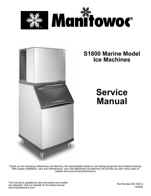
<strong>S1800</strong> <strong>Marine</strong> <strong>Model</strong><br />
<strong>Ice</strong> <strong>Machines</strong><br />
<strong>Service</strong><br />
<strong>Manual</strong><br />
Thank you for selecting a <strong>Manitowoc</strong> <strong>Ice</strong> Machine, the dependability leader in ice making equipment and related products.<br />
With proper installation, care and maintenance, your new <strong>Manitowoc</strong> <strong>Ice</strong> Machine will provide you with many years of<br />
reliable and economical performance.<br />
This manual is updated as new information and models<br />
are released. Visit our website for the latest manual.<br />
www.manitowocice.com<br />
Part Number 80-1634-3<br />
9/2004
Safety Notices<br />
As you work on a S-Series <strong>Ice</strong> Machine, be sure to pay<br />
close attention to the safety notices in this manual.<br />
Disregarding the notices may lead to serious injury and/<br />
or damage to the ice machine.<br />
Throughout this manual, you will see the following types<br />
of safety notices:<br />
! Warning<br />
PERSONAL INJURY POTENTIAL<br />
Do not operate equipment that has been misused,<br />
abused, neglected, damaged, or altered/modified<br />
from that of original manufactured specifications.<br />
! Warning<br />
Text in a Warning box alerts you to a potential<br />
personal injury situation. Be sure to read the<br />
Warning statement before proceeding, and work<br />
carefully.<br />
! Caution<br />
Text in a Caution box alerts you to a situation in<br />
which you could damage the ice machine. Be sure<br />
to read the Caution statement before proceeding,<br />
and work carefully.<br />
Procedural Notices<br />
As you work on a S-Series <strong>Ice</strong> Machine, be sure to read<br />
the procedural notices in this manual. These notices<br />
supply helpful information which may assist you as you<br />
work.<br />
Throughout this manual, you will see the following types<br />
of procedural notices:<br />
Important<br />
Text in an Important box provides you with<br />
information that may help you perform a procedure<br />
more efficiently. Disregarding this information will<br />
not cause damage or injury, but it may slow you<br />
down as you work.<br />
NOTE: Text set off as a Note provides you with simple,<br />
but useful, extra information about the procedure you<br />
are performing.<br />
Read These Before Proceeding:<br />
! Caution<br />
Proper installation, care and maintenance are<br />
essential for maximum ice production and troublefree<br />
operation of you <strong>Manitowoc</strong> <strong>Ice</strong> Machine.<br />
Read and understand this manual. It contains<br />
valuable care and maintenance information. If you<br />
encounter problems not covered by this manual, do<br />
not proceed, contact <strong>Manitowoc</strong> <strong>Ice</strong>, Inc. We will be<br />
happy to provide assistance.<br />
Important<br />
Routine adjustments and maintenance procedures<br />
outlined in this manual are not covered by the<br />
warranty.<br />
We reserve the right to make product improvements at any time.<br />
Specifications and design are subject to change without notice.
Section 1<br />
General Information<br />
Section 2<br />
Installation Instructions<br />
Table of Contents<br />
<strong>Model</strong> Numbers . . . . . . . . . . . . . . . . . . . . . . . . . . . . . . . . . . . . . . . . . . . . . . . . . 1-1<br />
How to Read a <strong>Model</strong> Number . . . . . . . . . . . . . . . . . . . . . . . . . . . . . . . . . . . . . 1-1<br />
<strong>Ice</strong> Cube Sizes . . . . . . . . . . . . . . . . . . . . . . . . . . . . . . . . . . . . . . . . . . . . . . . . . . 1-1<br />
Accessories . . . . . . . . . . . . . . . . . . . . . . . . . . . . . . . . . . . . . . . . . . . . . . . . . . . . 1-2<br />
Bin Caster . . . . . . . . . . . . . . . . . . . . . . . . . . . . . . . . . . . . . . . . . . . . . . . . . . 1-2<br />
<strong>Ice</strong> Bagger . . . . . . . . . . . . . . . . . . . . . . . . . . . . . . . . . . . . . . . . . . . . . . . . . . 1-2<br />
Guardian Sachet Packets . . . . . . . . . . . . . . . . . . . . . . . . . . . . . . . . . . . . . . 1-2<br />
Arctic Pure Water Filter System . . . . . . . . . . . . . . . . . . . . . . . . . . . . . . . . . 1-2<br />
<strong>Manitowoc</strong> Cleaner and Sanitizer . . . . . . . . . . . . . . . . . . . . . . . . . . . . . . . . 1-2<br />
AuCS® Automatic Cleaning System . . . . . . . . . . . . . . . . . . . . . . . . . . . . . . 1-2<br />
Dispenser . . . . . . . . . . . . . . . . . . . . . . . . . . . . . . . . . . . . . . . . . . . . . . . . . . 1-2<br />
<strong>Model</strong>/Serial Number Location . . . . . . . . . . . . . . . . . . . . . . . . . . . . . . . . . . . . . 1-3<br />
Owner Warranty Registration Card . . . . . . . . . . . . . . . . . . . . . . . . . . . . . . . . . 1-4<br />
General . . . . . . . . . . . . . . . . . . . . . . . . . . . . . . . . . . . . . . . . . . . . . . . . . . . . 1-4<br />
Warranty Coverage . . . . . . . . . . . . . . . . . . . . . . . . . . . . . . . . . . . . . . . . . . . . . . 1-4<br />
General . . . . . . . . . . . . . . . . . . . . . . . . . . . . . . . . . . . . . . . . . . . . . . . . . . . . 1-4<br />
Parts . . . . . . . . . . . . . . . . . . . . . . . . . . . . . . . . . . . . . . . . . . . . . . . . . . . . . . 1-4<br />
Labor . . . . . . . . . . . . . . . . . . . . . . . . . . . . . . . . . . . . . . . . . . . . . . . . . . . . . . 1-4<br />
Exclusions . . . . . . . . . . . . . . . . . . . . . . . . . . . . . . . . . . . . . . . . . . . . . . . . . . 1-4<br />
Authorized Warranty <strong>Service</strong> . . . . . . . . . . . . . . . . . . . . . . . . . . . . . . . . . . . 1-4<br />
General . . . . . . . . . . . . . . . . . . . . . . . . . . . . . . . . . . . . . . . . . . . . . . . . . . . . . . . . 2-1<br />
<strong>Ice</strong> Machine Dimensions . . . . . . . . . . . . . . . . . . . . . . . . . . . . . . . . . . . . . . . . . . 2-1<br />
<strong>S1800</strong> Water-Cooled <strong>Ice</strong> <strong>Machines</strong> . . . . . . . . . . . . . . . . . . . . . . . . . . . . . . 2-1<br />
Location of <strong>Ice</strong> Machine . . . . . . . . . . . . . . . . . . . . . . . . . . . . . . . . . . . . . . . . . . 2-2<br />
<strong>Ice</strong> Machine Heat of Rejection . . . . . . . . . . . . . . . . . . . . . . . . . . . . . . . . . . . . . 2-2<br />
Electrical <strong>Service</strong> . . . . . . . . . . . . . . . . . . . . . . . . . . . . . . . . . . . . . . . . . . . . . . . . 2-3<br />
General . . . . . . . . . . . . . . . . . . . . . . . . . . . . . . . . . . . . . . . . . . . . . . . . . . . . 2-3<br />
Voltage . . . . . . . . . . . . . . . . . . . . . . . . . . . . . . . . . . . . . . . . . . . . . . . . . . . . 2-3<br />
Minimum Circuit Ampacity . . . . . . . . . . . . . . . . . . . . . . . . . . . . . . . . . . . . . 2-3<br />
Electrical Requirements . . . . . . . . . . . . . . . . . . . . . . . . . . . . . . . . . . . . . . . 2-3<br />
Self-Contained Electrical Wiring Connections . . . . . . . . . . . . . . . . . . . . . . . . 2-4<br />
Self Contained <strong>Ice</strong> Machine<br />
115/1/60 or 208-230/1/60 . . . . . . . . . . . . . . . . . . . . . . . . . . . . . . . . . . . . . . 2-4<br />
Self Contained <strong>Ice</strong> Machine<br />
208-230/3/60 . . . . . . . . . . . . . . . . . . . . . . . . . . . . . . . . . . . . . . . . . . . . . . . . 2-4<br />
Self Contained <strong>Ice</strong> Machine<br />
230/1/50 . . . . . . . . . . . . . . . . . . . . . . . . . . . . . . . . . . . . . . . . . . . . . . . . . . . 2-4<br />
For United Kingdom Only . . . . . . . . . . . . . . . . . . . . . . . . . . . . . . . . . . . . . . . . . 2-4<br />
Water Supply and Drain Requirements . . . . . . . . . . . . . . . . . . . . . . . . . . . . . . 2-5<br />
Water Supply . . . . . . . . . . . . . . . . . . . . . . . . . . . . . . . . . . . . . . . . . . . . . . . 2-5<br />
Water Inlet Lines . . . . . . . . . . . . . . . . . . . . . . . . . . . . . . . . . . . . . . . . . . . . . 2-5<br />
Drain Connections . . . . . . . . . . . . . . . . . . . . . . . . . . . . . . . . . . . . . . . . . . . 2-5<br />
Cooling Tower Applications . . . . . . . . . . . . . . . . . . . . . . . . . . . . . . . . . . . . . . . 2-5<br />
Water Supply and Drain Line Sizing/Connections . . . . . . . . . . . . . . . . . . . 2-6<br />
Installation Check List . . . . . . . . . . . . . . . . . . . . . . . . . . . . . . . . . . . . . . . . . . . . 2-7<br />
Before Starting the <strong>Ice</strong> Machine . . . . . . . . . . . . . . . . . . . . . . . . . . . . . . . . . . . . 2-8<br />
AuCS® Automatic Cleaning System . . . . . . . . . . . . . . . . . . . . . . . . . . . . . . . . 2-8<br />
Part No. 80-1634-3 1
Section 3<br />
<strong>Ice</strong> Machine Operation<br />
Section 4<br />
Maintenance<br />
Section 5<br />
Before Calling For <strong>Service</strong><br />
Table of Contents (continued)<br />
Component Identification . . . . . . . . . . . . . . . . . . . . . . . . . . . . . . . . . . . . . . . . . 3-1<br />
Sequence Of Operation . . . . . . . . . . . . . . . . . . . . . . . . . . . . . . . . . . . . . . . . . . . 3-2<br />
Initial Start-Up or Start-Up After Automatic Shut-Off . . . . . . . . . . . . . . . . . . 3-2<br />
Freeze Sequence . . . . . . . . . . . . . . . . . . . . . . . . . . . . . . . . . . . . . . . . . . . . 3-2<br />
Harvest Sequence . . . . . . . . . . . . . . . . . . . . . . . . . . . . . . . . . . . . . . . . . . . . 3-3<br />
Automatic Shut-Off . . . . . . . . . . . . . . . . . . . . . . . . . . . . . . . . . . . . . . . . . . . 3-3<br />
Safety Timers . . . . . . . . . . . . . . . . . . . . . . . . . . . . . . . . . . . . . . . . . . . . . . . . 3-3<br />
Warm Water Rinse Cycle . . . . . . . . . . . . . . . . . . . . . . . . . . . . . . . . . . . . . . 3-3<br />
Operational Checks . . . . . . . . . . . . . . . . . . . . . . . . . . . . . . . . . . . . . . . . . . . . . . 3-4<br />
General . . . . . . . . . . . . . . . . . . . . . . . . . . . . . . . . . . . . . . . . . . . . . . . . . . . . 3-4<br />
Water Level . . . . . . . . . . . . . . . . . . . . . . . . . . . . . . . . . . . . . . . . . . . . . . . . . 3-4<br />
<strong>Ice</strong> Thickness Check . . . . . . . . . . . . . . . . . . . . . . . . . . . . . . . . . . . . . . . . . . 3-4<br />
Harvest Sequence Water Purge . . . . . . . . . . . . . . . . . . . . . . . . . . . . . . . . . 3-5<br />
General . . . . . . . . . . . . . . . . . . . . . . . . . . . . . . . . . . . . . . . . . . . . . . . . . . . . . . . . 4-1<br />
<strong>Ice</strong> Machine Inspection . . . . . . . . . . . . . . . . . . . . . . . . . . . . . . . . . . . . . . . . . . . 4-1<br />
Exterior Cleaning . . . . . . . . . . . . . . . . . . . . . . . . . . . . . . . . . . . . . . . . . . . . . . . . 4-1<br />
Water-Cooled Condenser and Water Regulating Valve . . . . . . . . . . . . . . . . . 4-1<br />
AlphaSan . . . . . . . . . . . . . . . . . . . . . . . . . . . . . . . . . . . . . . . . . . . . . . . . . . . . . . . 4-1<br />
Guardian . . . . . . . . . . . . . . . . . . . . . . . . . . . . . . . . . . . . . . . . . . . . . . . . . . . . . . . 4-2<br />
Installation . . . . . . . . . . . . . . . . . . . . . . . . . . . . . . . . . . . . . . . . . . . . . . . . . . 4-2<br />
Sachet Replacement Frequency . . . . . . . . . . . . . . . . . . . . . . . . . . . . . . . . . 4-2<br />
Sachet Replacement Procedure . . . . . . . . . . . . . . . . . . . . . . . . . . . . . . . . . 4-2<br />
Clean Up Procedure for Damaged Packet . . . . . . . . . . . . . . . . . . . . . . . . . 4-2<br />
Interior Cleaning and Sanitizing . . . . . . . . . . . . . . . . . . . . . . . . . . . . . . . . . . . . 4-3<br />
General . . . . . . . . . . . . . . . . . . . . . . . . . . . . . . . . . . . . . . . . . . . . . . . . . . . . 4-3<br />
Cleaning Procedure . . . . . . . . . . . . . . . . . . . . . . . . . . . . . . . . . . . . . . . . . . . 4-3<br />
Sanitizing Procedure . . . . . . . . . . . . . . . . . . . . . . . . . . . . . . . . . . . . . . . . . . 4-4<br />
Removal of Parts For Cleaning/Sanitizing . . . . . . . . . . . . . . . . . . . . . . . . . . 4-5<br />
Removal from <strong>Service</strong>/Winterization . . . . . . . . . . . . . . . . . . . . . . . . . . . . . . . . 4-12<br />
General . . . . . . . . . . . . . . . . . . . . . . . . . . . . . . . . . . . . . . . . . . . . . . . . . . . . 4-12<br />
Self-Contained Water-Cooled <strong>Ice</strong> <strong>Machines</strong> . . . . . . . . . . . . . . . . . . . . . . . . 4-12<br />
AuCS Accessory . . . . . . . . . . . . . . . . . . . . . . . . . . . . . . . . . . . . . . . . . . . . . 4-12<br />
Checklist . . . . . . . . . . . . . . . . . . . . . . . . . . . . . . . . . . . . . . . . . . . . . . . . . . . . . . . 5-1<br />
Safety Limit Feature . . . . . . . . . . . . . . . . . . . . . . . . . . . . . . . . . . . . . . . . . . . . . . 5-2<br />
2 Part No. 80-1634-3
Section 6<br />
Electrical System<br />
Section 7<br />
Refrigeration System<br />
Table of Contents (continued)<br />
Energized Parts Charts . . . . . . . . . . . . . . . . . . . . . . . . . . . . . . . . . . . . . . . . . . . 6-1<br />
Self-Contained Water-Cooled <strong>Model</strong>s . . . . . . . . . . . . . . . . . . . . . . . . . . . . 6-1<br />
Wiring Diagram Sequence of Operation . . . . . . . . . . . . . . . . . . . . . . . . . . . . . 6-2<br />
Self-Contained <strong>Model</strong>s . . . . . . . . . . . . . . . . . . . . . . . . . . . . . . . . . . . . . . . . 6-2<br />
Wiring Diagrams . . . . . . . . . . . . . . . . . . . . . . . . . . . . . . . . . . . . . . . . . . . . . . . . 6-9<br />
Wiring Diagram Legend . . . . . . . . . . . . . . . . . . . . . . . . . . . . . . . . . . . . . . . 6-9<br />
<strong>S1800</strong> - Self-Contained - 1 Phase . . . . . . . . . . . . . . . . . . . . . . . . . . . . . . . 6-10<br />
<strong>S1800</strong> - Self-Contained - 3 Phase . . . . . . . . . . . . . . . . . . . . . . . . . . . . . . . 6-11<br />
Component Specifications and Diagnostics . . . . . . . . . . . . . . . . . . . . . . . . . . 6-12<br />
Main Fuse . . . . . . . . . . . . . . . . . . . . . . . . . . . . . . . . . . . . . . . . . . . . . . . . . . 6-12<br />
Bin Switch . . . . . . . . . . . . . . . . . . . . . . . . . . . . . . . . . . . . . . . . . . . . . . . . . . 6-12<br />
Compressor Electrical Diagnostics . . . . . . . . . . . . . . . . . . . . . . . . . . . . . . . 6-14<br />
PTCR Diagnostics . . . . . . . . . . . . . . . . . . . . . . . . . . . . . . . . . . . . . . . . . . . . 6-15<br />
Diagnosing Start Components . . . . . . . . . . . . . . . . . . . . . . . . . . . . . . . . . . 6-18<br />
Harvest Assist Air Compressor . . . . . . . . . . . . . . . . . . . . . . . . . . . . . . . . . . 6-18<br />
ICE/OFF/CLEAN Toggle Switch . . . . . . . . . . . . . . . . . . . . . . . . . . . . . . . . . 6-19<br />
Electronic Control Board . . . . . . . . . . . . . . . . . . . . . . . . . . . . . . . . . . . . . . . 6-20<br />
<strong>Ice</strong> Thickness Probe (Harvest Initiation) . . . . . . . . . . . . . . . . . . . . . . . . . . . . . 6-22<br />
How The Probe Works . . . . . . . . . . . . . . . . . . . . . . . . . . . . . . . . . . . . . . . . 6-22<br />
Harvest Light . . . . . . . . . . . . . . . . . . . . . . . . . . . . . . . . . . . . . . . . . . . . . . . . 6-22<br />
Freeze Time Lock-In Feature . . . . . . . . . . . . . . . . . . . . . . . . . . . . . . . . . . . 6-22<br />
Maximum Freeze Time . . . . . . . . . . . . . . . . . . . . . . . . . . . . . . . . . . . . . . . . 6-22<br />
<strong>Ice</strong> Thickness Check . . . . . . . . . . . . . . . . . . . . . . . . . . . . . . . . . . . . . . . . . . 6-22<br />
Diagnosing <strong>Ice</strong> Thickness Control Circuitry . . . . . . . . . . . . . . . . . . . . . . . . 6-23<br />
Water Level Control Circuitry . . . . . . . . . . . . . . . . . . . . . . . . . . . . . . . . . . . . . . 6-24<br />
Water Level Probe Light . . . . . . . . . . . . . . . . . . . . . . . . . . . . . . . . . . . . . . . 6-24<br />
Water Inlet Valve Safety Shut-Off . . . . . . . . . . . . . . . . . . . . . . . . . . . . . . . . 6-24<br />
Freeze Cycle Circuitry . . . . . . . . . . . . . . . . . . . . . . . . . . . . . . . . . . . . . . . . . 6-24<br />
Harvest Cycle Circuitry . . . . . . . . . . . . . . . . . . . . . . . . . . . . . . . . . . . . . . . . 6-24<br />
Diagnosing Water Level Control Circuitry . . . . . . . . . . . . . . . . . . . . . . . . . . 6-25<br />
Diagnosing An <strong>Ice</strong> Machine That Will Not Run . . . . . . . . . . . . . . . . . . . . . . . . 6-27<br />
Sequence of Operation . . . . . . . . . . . . . . . . . . . . . . . . . . . . . . . . . . . . . . . . . . . 7-1<br />
Self-Contained Water-Cooled <strong>Model</strong>s . . . . . . . . . . . . . . . . . . . . . . . . . . . . 7-1<br />
<strong>S1800</strong> Self-Contained Tubing Schematic . . . . . . . . . . . . . . . . . . . . . . . . . . 7-3<br />
Operational Analysis (Diagnostics) . . . . . . . . . . . . . . . . . . . . . . . . . . . . . . . . . 7-4<br />
General . . . . . . . . . . . . . . . . . . . . . . . . . . . . . . . . . . . . . . . . . . . . . . . . . . . . 7-4<br />
Before Beginning <strong>Service</strong> . . . . . . . . . . . . . . . . . . . . . . . . . . . . . . . . . . . . . . 7-5<br />
<strong>Ice</strong> Production Check . . . . . . . . . . . . . . . . . . . . . . . . . . . . . . . . . . . . . . . . . 7-5<br />
Installation/Visual Inspection Checklist . . . . . . . . . . . . . . . . . . . . . . . . . . . . 7-6<br />
Water System Checklist . . . . . . . . . . . . . . . . . . . . . . . . . . . . . . . . . . . . . . . 7-6<br />
<strong>Ice</strong> Formation Pattern . . . . . . . . . . . . . . . . . . . . . . . . . . . . . . . . . . . . . . . . . 7-7<br />
Safety Limits . . . . . . . . . . . . . . . . . . . . . . . . . . . . . . . . . . . . . . . . . . . . . . . . 7-9<br />
Analyzing Discharge Pressure<br />
During Freeze or Harvest Cycle . . . . . . . . . . . . . . . . . . . . . . . . . . . . . . . . . 7-12<br />
Analyzing Suction Pressure<br />
During Freeze Cycle . . . . . . . . . . . . . . . . . . . . . . . . . . . . . . . . . . . . . . . . . . 7-13<br />
Harvest Valve Temperature Check . . . . . . . . . . . . . . . . . . . . . . . . . . . . . . . 7-15<br />
Discharge Line Temperature Analysis . . . . . . . . . . . . . . . . . . . . . . . . . . . . 7-16<br />
How to Use the Refrigeration System<br />
Operational Analysis Tables . . . . . . . . . . . . . . . . . . . . . . . . . . . . . . . . . . . . 7-17<br />
Refrigeration System Operational Analysis Tables . . . . . . . . . . . . . . . . . . . 7-18<br />
Pressure Control Specifications and Diagnostics . . . . . . . . . . . . . . . . . . . . . 7-19<br />
High Pressure Cut-Out (HPCO) Control . . . . . . . . . . . . . . . . . . . . . . . . . . . 7-19<br />
Cycle Time/24 Hour <strong>Ice</strong> Production/Refrigerant Pressure Charts . . . . . . . . . 7-20<br />
Part No. 80-1634-3 3
Table of Contents (continued)<br />
Refrigerant Recovery/Evacuation and Recharging . . . . . . . . . . . . . . . . . . . . . 7-21<br />
Normal Self-Contained <strong>Model</strong> Procedures . . . . . . . . . . . . . . . . . . . . . . . . . 7-21<br />
System Contamination Clean-Up . . . . . . . . . . . . . . . . . . . . . . . . . . . . . . . . 7-23<br />
Replacing Pressure Controls Without<br />
Removing Refrigerant Charge . . . . . . . . . . . . . . . . . . . . . . . . . . . . . . . . . . . 7-25<br />
Filter-Driers . . . . . . . . . . . . . . . . . . . . . . . . . . . . . . . . . . . . . . . . . . . . . . . . . 7-27<br />
Total System Refrigerant Charges . . . . . . . . . . . . . . . . . . . . . . . . . . . . . . . 7-28<br />
Refrigerant Definitions . . . . . . . . . . . . . . . . . . . . . . . . . . . . . . . . . . . . . . . . . 7-29<br />
Refrigerant Re-Use Policy . . . . . . . . . . . . . . . . . . . . . . . . . . . . . . . . . . . . . . 7-30<br />
HFC Refrigerant Questions and Answers . . . . . . . . . . . . . . . . . . . . . . . . . . 7-31<br />
4 Part No. 80-1634-3
Section 1 General Information<br />
<strong>Model</strong> Numbers<br />
This manual covers the following models:<br />
Self-Contained<br />
Water-Cooled<br />
SR1801WM<br />
SD1803WM<br />
SY1805WM<br />
NOTE: <strong>Model</strong> numbers ending in 3 indicate a 3-phase<br />
unit. Example: SY1805WM3<br />
! Warning<br />
PERSONAL INJURY POTENTIAL<br />
Do not operate equipment that has been misused,<br />
abused, neglected, damaged, or altered/modified<br />
from that of original manufactured specifications.<br />
! Warning<br />
PERSONAL INJURY POTENTIAL<br />
Remove all ice machine panels before lifting and<br />
installing.<br />
Section 1<br />
General Information<br />
How to Read a <strong>Model</strong> Number<br />
ICE MACHINE<br />
MODEL<br />
ICE CUBE SIZE<br />
R REGULAR<br />
D DICE<br />
Y HALF DICE<br />
<strong>Ice</strong> Cube Sizes<br />
# CUBE SIZE CONDENSER TYPE<br />
1 REGULAR WATER-COOLED<br />
3 DICE WATER-COOLED<br />
5 HALF-DICE WATER-COOLED<br />
S R 1801 W M<br />
ICE MACHINE<br />
SERIES<br />
CONDENSER TYPE<br />
MARINE MODEL<br />
W SELF-CONTAINED WATER-COOLED<br />
Regular<br />
Dice<br />
Half Dice<br />
1-1/8" x 1-1/8" x 7/8" 7/8" x 7/8" x 7/8" 3/8" x 1-1/8" x 7/8"<br />
2.86 x 2.86 x 2.22 cm 2.22 x 2.22 x 2.22 cm 0.95 x 2.86 x 2.22 cm<br />
Part Number 80-1634-3 1-1
General Information Section 1<br />
Accessories<br />
Contact your <strong>Manitowoc</strong> distributor for these optional<br />
accessories:<br />
BIN CASTER<br />
Replaces standard legs.<br />
ICE BAGGER<br />
Maximize profits from bagged ice sales with this<br />
convenient accessory. This sturdy unit rests on the bin<br />
door frame, and adapts for left or right side filling.<br />
GUARDIAN SACHET PACKETS<br />
Guardian sachet packets release chlorine dioxide on a<br />
controlled basis to inhibit the growth of bacteria and<br />
slime.<br />
Guardian sachet packets are available through your<br />
local <strong>Manitowoc</strong> <strong>Ice</strong> Machine dealer.<br />
ARCTIC PURE WATER FILTER SYSTEM<br />
Engineered specifically for <strong>Manitowoc</strong> ice machines,<br />
This water filter is an efficient, dependable, and<br />
affordable method of inhibiting scale formation, filtering<br />
sediment, and removing chlorine taste and odor.<br />
MANITOWOC CLEANER AND SANITIZER<br />
<strong>Manitowoc</strong> <strong>Ice</strong> Machine Cleaner and Sanitizer are<br />
available in convenient 16 oz. (473 ml) bottles. These<br />
are the only cleaner and sanitizer approved for use with<br />
<strong>Manitowoc</strong> products.<br />
Cleaner Part Number Sanitizer Part Number<br />
16 ounce Bottle - 94-0546-3 16 ounce Bottle - 94-0565-3<br />
AuCS®-SO - 94-0546-3 AuCS®-SO - 94-0565-3<br />
AuCS®-SI - 40-1326-3 AuCS®-SI - 40-1327-3<br />
AUCS® AUTOMATIC CLEANING SYSTEM<br />
This accessory reduces equipment cleaning expense.<br />
The AuCS® accessory monitors ice making cycles and<br />
initiates cleaning procedures automatically.<br />
DISPENSER<br />
A counter-top dispenser is ideal for cafeterias and many<br />
types of self-service facilities. <strong>Manitowoc</strong> auto-fill, floorstanding<br />
ice dispensers meet the strict sanitary<br />
requirements of the food service, lodging and health<br />
care industries.<br />
1-2 Part Number 80-1634-3
Section 1 General Information<br />
<strong>Model</strong>/Serial Number Location<br />
These numbers are required when requesting<br />
information from your local <strong>Manitowoc</strong> distributor, or<br />
<strong>Manitowoc</strong> <strong>Ice</strong>, Inc.<br />
SV13147<br />
MODEL/SERIAL DECAL<br />
LOCATION<br />
<strong>Model</strong>/Serial Number Location<br />
The model and serial number are listed on the MODEL/<br />
SERIAL NUMBER DECAL affixed to the ice machine,<br />
remote condenser and storage bin.<br />
Part Number 80-1634-3 1-3
General Information Section 1<br />
Owner Warranty Registration Card<br />
GENERAL<br />
The packet containing this manual also includes<br />
warranty information. Warranty coverage begins the day<br />
your new ice machine is installed.<br />
Important<br />
Complete and mail the OWNER WARRANTY<br />
REGISTARATION CARD as soon as possible to<br />
validate the installation date.<br />
If you do not return your OWNER WARRANTY<br />
REGISTRATION CARD, <strong>Manitowoc</strong> will use the date of<br />
sale to the <strong>Manitowoc</strong> Distributor as the first day of<br />
warranty coverage for your new ice machine.<br />
Warranty Coverage<br />
GENERAL<br />
The following Warranty outline is provided for your<br />
convenience. For a detailed explanation, read the<br />
warranty bond shipped with each product.<br />
Contact your local <strong>Manitowoc</strong> Distributor, <strong>Manitowoc</strong> <strong>Ice</strong>,<br />
Inc. or visit our website at www.manitowocice.com if you<br />
need further warranty information.<br />
Important<br />
This product is intended exclusively for commercial<br />
application. No warranty is extended for personal,<br />
family, or household purposes.<br />
PARTS<br />
1. <strong>Manitowoc</strong> warrants the ice machine against defects<br />
in materials and workmanship, under normal use<br />
and service for three (3) years from the date of<br />
original installation.<br />
2. The evaporator and compressor are covered by an<br />
additional two (2) year (five years total) warranty<br />
beginning on the date of the original installation.<br />
LABOR<br />
1. Labor required to repair or replace defective<br />
components is covered for three (3) years from the<br />
date of original installation.<br />
2. The evaporator is covered by an additional two (2)<br />
year (five years total) labor warranty beginning on<br />
the date of the original installation.<br />
EXCLUSIONS<br />
The following items are not included in the ice machine’s<br />
warranty coverage:<br />
1. Normal maintenance, adjustments and cleaning.<br />
2. Repairs due to unauthorized modifications to the<br />
ice machine or use of non-standard parts without<br />
prior written approval from <strong>Manitowoc</strong> <strong>Ice</strong>, Inc.<br />
3. Damage caused by improper installation of the ice<br />
machine, electrical supply, water supply or drainage,<br />
or damage caused by floods, storms, or other acts of<br />
God.<br />
4. Premium labor rates due to holidays, overtime,<br />
etc.; travel time; flat rate service call charges;<br />
mileage and miscellaneous tools and material<br />
charges not listed on the payment schedule.<br />
Additional labor charges resulting from the<br />
inaccessibility of equipment are also excluded.<br />
5. Parts or assemblies subjected to misuse, abuse,<br />
neglect or accidents.<br />
6. Damage or problems caused by installation,<br />
cleaning and/or maintenance procedures<br />
inconsistent with the technical instructions<br />
provided in this manual.<br />
7. This product is intended exclusively for<br />
commercial application. No warranty is extended<br />
for personal, family, or household purposes.<br />
AUTHORIZED WARRANTY SERVICE<br />
To comply with the provisions of the warranty, a<br />
refrigeration service company qualified and<br />
authorized by a <strong>Manitowoc</strong> distributor, or a<br />
Contracted <strong>Service</strong> Representative must perform the<br />
warranty repair.<br />
NOTE: If the dealer you purchased the ice machine from<br />
is not authorized to perform warranty service, contact<br />
your <strong>Manitowoc</strong> distributor or <strong>Manitowoc</strong> <strong>Ice</strong>, Inc. for the<br />
name of the nearest authorized service representative.<br />
<strong>Service</strong> Calls<br />
Normal maintenance, adjustments and cleaning as<br />
outlined in this manual are not covered by the<br />
warranty. If you have followed the procedures listed on<br />
page 5-1 of this manual, and the ice machine still does<br />
not perform properly, call your authorized service<br />
company.<br />
1-4 Part Number 80-1634-3
Section 2 Installation Instructions<br />
General<br />
These instructions are provided to assist the qualified<br />
installer. Check your local Yellow Pages for the name of<br />
the nearest <strong>Manitowoc</strong> distributor, or call <strong>Manitowoc</strong> <strong>Ice</strong>,<br />
Inc. for information regarding start-up services.<br />
<strong>Ice</strong> Machine Dimensions<br />
<strong>S1800</strong> WATER-COOLED ICE MACHINES<br />
A<br />
B<br />
4.0"<br />
(10.2cm)<br />
2.50" (6.35cm)<br />
1.1" (2.8cm)<br />
7.8" (19.8cm)<br />
C<br />
10.25" (26.0cm)<br />
11.0" (27.9cm)<br />
2.0" (5.1cm)<br />
E<br />
F<br />
Width, Depth, and Height Dimensions<br />
Electrical and AuCS Dimensions<br />
W<br />
11.0" (27.9cm)<br />
Section 2<br />
Installation Instructions<br />
5.75" (14.6cm)<br />
3.0" (7.6cm)<br />
3.75" (9.5cm)<br />
D<br />
H<br />
Important<br />
Failure to follow these installation guidelines may<br />
affect warranty coverage.<br />
Part Number 80-1634-3 2-1<br />
ELECTRICAL<br />
AUXILLARY BASE DRAIN<br />
1/2"CPVC SOCKET<br />
WATER INLET<br />
3/8"FPT<br />
AuCS<br />
Connections<br />
DRAIN 1/2"NPTF<br />
CONDENSER WATER<br />
OUTLET 1/2"FPT<br />
(Water-Cooled Only)<br />
CONDENSER WATER<br />
INLET 3/8"FPT<br />
(Water-Cooled Only)<br />
<strong>Ice</strong> Machine Dimension W Dimension D Dimension H<br />
<strong>S1800</strong>M 48 in. (121.9 cm) 24.5 in. (62.2 cm) 29.5 in (74.9 cm)<br />
<strong>Ice</strong> Machine<br />
Electrical<br />
Dimension A Dimension B Dimension C<br />
AuCS<br />
Dimension E Dimension F<br />
<strong>S1800</strong>M 22.75 in (57.8 cm) 22.25 in (56.5 cm) 14.0 in (35.6 cm) 9.5 in (24.1 cm) 7.5 in (19.1 cm)
Installation Instructions Section 2<br />
Location of <strong>Ice</strong> Machine<br />
The location selected for the ice machine must meet the<br />
following criteria. If any of these criteria are not met,<br />
select another location.<br />
• The location must be free of airborne and other<br />
contaminants.<br />
• The air temperature must be at least 35°F (1.6°C),<br />
but must not exceed 110°F (43.4°C).<br />
• The location must not be near heat-generating<br />
equipment or in direct sunlight and must be protected<br />
from weather.<br />
• The location must not obstruct air flow through or<br />
around the ice machine. Refer to the chart below for<br />
clearance requirements.<br />
<strong>S1800</strong>M Water-Cooled*<br />
Top/Sides 8" (20.3 cm)<br />
Back 5" (12.7 cm)<br />
*There is no minimum clearance required for water-cooled or remote<br />
ice machines. This value is recommended for efficient operation and<br />
servicing only.<br />
! Caution<br />
The ice machine must be protected if it will be<br />
subjected to temperatures below 32°F (0°C).<br />
Failure caused by exposure to freezing<br />
temperatures is not covered by the warranty. See<br />
“Removal from <strong>Service</strong>/Winterization”.<br />
<strong>Ice</strong> Machine Heat of Rejection<br />
Series<br />
Heat of Rejection<br />
<strong>Ice</strong> Machine Air Conditioning Peak<br />
<strong>S1800</strong>M 24000 36000<br />
B.T.U./Hour<br />
Because the heat of rejection varies during the ice making cycle,<br />
the figure shown is an average.<br />
<strong>Ice</strong> machines, like other refrigeration equipment, reject<br />
heat through the condenser. It is helpful to know the<br />
amount of heat rejected by the ice machine when sizing<br />
air conditioning equipment where self-contained aircooled<br />
ice machines are installed.<br />
This information is also necessary when evaluating the<br />
benefits of using water-cooled or remote condensers to<br />
reduce air conditioning loads. The amount of heat added<br />
to an air conditioned environment by an ice machine<br />
using a water-cooled or remote condenser is negligible.<br />
Knowing the amount of heat rejected is also important<br />
when sizing a cooling tower for a water-cooled<br />
condenser. Use the peak figure for sizing the cooling<br />
tower.<br />
2-2 Part Number 80-1634-3
Section 2 Installation Instructions<br />
Electrical <strong>Service</strong><br />
GENERAL<br />
! Warning<br />
All wiring must conform to local, state and national<br />
codes.<br />
VOLTAGE<br />
The maximum allowable voltage variation is ±10% of the<br />
rated voltage at ice machine start-up (when the electrical<br />
load is highest).<br />
! Warning<br />
The ice machine must be grounded in accordance<br />
with national and local electrical codes.<br />
Important<br />
Observe correct polarity of incoming line voltage.<br />
Fuse/Circuit Breaker<br />
A separate fuse/circuit breaker must be provided for<br />
each ice machine. Circuit breakers must be H.A.C.R.<br />
rated (does not apply in Canada).<br />
MINIMUM CIRCUIT AMPACITY<br />
The minimum circuit ampacity is used to help select the<br />
wire size of the electrical supply. (Minimum circuit<br />
ampacity is not the ice machine’s running amp load.)<br />
The wire size (or gauge) is also dependent upon<br />
location, materials used, length of run, etc., so it must be<br />
determined by a qualified electrician.<br />
ELECTRICAL REQUIREMENTS<br />
Refer to <strong>Ice</strong> Machine <strong>Model</strong>/Serial Plate for voltage/<br />
amperage specifications.<br />
S Series <strong>Ice</strong> <strong>Machines</strong> (* indicates preliminary data)<br />
<strong>Ice</strong> Machine<br />
Voltage Phase<br />
Cycle<br />
Water Cooled<br />
Maximum Fuse/Circuit<br />
Minimum Circuit Amps<br />
Breaker<br />
208-230/1/60 40 22.1<br />
<strong>S1800</strong><br />
208-230/3/60 20 12.0<br />
230/1/50 40 20.5<br />
Part Number 80-1634-3 2-3
Installation Instructions Section 2<br />
Self-Contained Electrical Wiring Connections<br />
! Warning<br />
These diagrams are not intended to show proper<br />
wire routing, wire sizing, disconnects, etc., only the<br />
correct wire connections.<br />
All electrical work, including wire routing and<br />
grounding, must conform to local, state and national<br />
electrical codes.<br />
Though wire nuts are shown in the drawings, the ice<br />
machine field wiring connections may use either<br />
wire nuts or screw terminals.<br />
SELF CONTAINED ICE MACHINE<br />
115/1/60 OR 208-230/1/60<br />
SV1258<br />
L 1<br />
GROUND<br />
ICE MACHINE<br />
CONNECTIONS<br />
For United Kingdom Only<br />
N=115V<br />
OR<br />
L2=208-230V<br />
L 1<br />
GROUND<br />
TO SEPARATE<br />
FUSE/BREAKER<br />
SELF CONTAINED ICE MACHINE<br />
208-230/3/60<br />
SELF CONTAINED ICE MACHINE<br />
230/1/50<br />
2-4 Part Number 80-1634-3<br />
SV1190<br />
SV1191<br />
L 1<br />
L 2<br />
L 3<br />
GROUND<br />
L 1<br />
N<br />
GROUND<br />
ICE MACHINE<br />
CONNECTIONS<br />
ICE MACHINE<br />
CONNECTIONS<br />
L 1<br />
L 2<br />
L 3<br />
GROUND<br />
TO SEPARATE<br />
FUSE/BREAKER<br />
L1<br />
N<br />
GROUND<br />
TO SEPARATE<br />
FUSE/BREAKER.<br />
DISCONNECT ALL<br />
POLES.<br />
As the colors of the wires in the mains lead of the appliance may not correspond with the colored markings<br />
identifying the terminals in your plug, proceed as follows:<br />
• The wire which is colored green and yellow must be connected to the terminal in the plug which is marked with<br />
the letter E or by the earth ground symbol or colored green or green and yellow.<br />
• The wire colored blue must be connected to the terminal which is marked with the letter N or colored black.<br />
• The wire colored brown must be connected to the terminal which is marked with the letter L or colored red.
Section 2 Installation Instructions<br />
Water Supply and Drain Requirements<br />
WATER SUPPLY<br />
Local water conditions may require treatment of the<br />
water to inhibit scale formation, filter sediment, and<br />
remove chlorine odor and taste.<br />
Important<br />
If you are installing a <strong>Manitowoc</strong> Arctic Pure water<br />
filter system, refer to the Installation Instructions<br />
supplied with the filter system for ice making water<br />
inlet connections.<br />
WATER INLET LINES<br />
Follow these guidelines to install water inlet lines:<br />
• Do not connect the ice machine to a hot water<br />
supply. Be sure all hot water restrictors installed for<br />
other equipment are working. (Check valves on sink<br />
faucets, dishwashers, etc.)<br />
• If water pressure exceeds the maximum<br />
recommended pressure, obtain a water pressure<br />
regulator from your <strong>Manitowoc</strong> distributor.<br />
• Install a water shut-off valve for both the ice making<br />
and condenser water lines.<br />
• Insulate water inlet lines to prevent condensation.<br />
! Caution<br />
Do not apply heat to water valve inlet fitting. This will<br />
damage plastic valve body.<br />
DRAIN CONNECTIONS<br />
Follow these guidelines when installing drain lines to<br />
prevent drain water from flowing back into the ice<br />
machine and storage bin:<br />
• Drain lines must have a 1.5 inch drop per 5 feet of<br />
run (2.5 cm per meter), and must not create traps.<br />
• The floor drain must be large enough to<br />
accommodate drainage from all drains.<br />
• Run separate bin and ice machine drain lines.<br />
Insulate them to prevent condensation.<br />
• Vent the bin and ice machine drain to the<br />
atmosphere. Do not vent the condenser drain on<br />
water-cooled models.<br />
Cooling Tower Applications<br />
A water cooling tower installation does not require<br />
modification of the ice machine. The water regulator<br />
valve for the condenser continues to control the<br />
refrigeration discharge pressure.<br />
It is necessary to know the amount of heat rejection, and<br />
the pressure drop through the condenser and water<br />
valves (inlet and outlet) when using a cooling tower on<br />
an ice machine.<br />
• Water entering the condenser must not exceed 90°F<br />
(32.2°C).<br />
• Water flow through the condenser must not exceed 5<br />
gallons (19 liters) per minute.<br />
• Allow for a pressure drop of 7 psi (48 kPA) between<br />
the condenser water inlet and the outlet of the ice<br />
machine.<br />
• Water exiting the condenser must not exceed 110°F<br />
(43.3°C).<br />
Part Number 80-1634-3 2-5
Installation Instructions Section 2<br />
WATER SUPPLY AND DRAIN LINE SIZING/CONNECTIONS<br />
! Caution<br />
Plumbing must conform to state and local codes.<br />
Location Water Temperature Water Pressure <strong>Ice</strong> Machine Fitting<br />
<strong>Ice</strong> Making<br />
Water Inlet<br />
<strong>Ice</strong> Making<br />
Water Drain<br />
Condenser<br />
Water Inlet<br />
Condenser<br />
Water Drain<br />
35°F (1.6°C) Min.<br />
90°F (32.2°C) Max.<br />
20 psi (137.9 kPA) Min.<br />
80 psi (551.5 kPA) Max.<br />
--- ---<br />
40°F (4.4°C) Min.<br />
90°F (32.2°C) Max.<br />
20 psi (137.9 kPA) Min.<br />
150 psi (1034.2 kPA) Max.<br />
--- ---<br />
Bin Drain --- ---<br />
ELECTRICAL ENTRANCE<br />
18” (46 CM) VENT TUBE<br />
1/2” DRAIN CONNECTION<br />
PLASTIC FITTING ON OPPOSITE<br />
SIDE DO NOT APPLY HEAT<br />
1/2” (1.3 CM) MIN<br />
DRAIN ID<br />
AIR GAP<br />
OPEN, TRAPPED AND<br />
VENTED DRAIN<br />
Typical Water Supply Drain Installation<br />
3/8" Female Pipe<br />
Thread<br />
1/2" Female<br />
Pipe Thread<br />
1/2" Female<br />
Pipe Thread<br />
3/4" Female<br />
Pipe Thread<br />
3/8" Female Pipe Thread<br />
Tubing Size Up to <strong>Ice</strong><br />
Machine Fitting<br />
3/8" (.95 cm) minimum<br />
inside diameter<br />
1/2" (1.27 cm) minimum<br />
inside diameter<br />
1/2" (1.27 cm) minimum<br />
inside diameter<br />
3/4" (1.91 cm) minimum<br />
inside diameter<br />
3/8” FPT ICE MAKING WATER INLET FITTING,<br />
PLASTIC FITTING ON OPPOSITE SIDE DO NOT<br />
APPLY HEAT<br />
3/8” FPT CONDENSER WATER INLET<br />
(WATER COOLED UNITS ONLY<br />
1/2” FPT CONDENSER WATER DRAIN<br />
(WATER COOLED UNITS ONLY)<br />
1/2” CPVC SOCKET AUXILLARY BASE<br />
DRAIN<br />
DO NOT TRAP DRAIN LINE,<br />
LEAVE AIR GAP BETWEEN<br />
DRAIN TUBE AND DRAIN<br />
2-6 Part Number 80-1634-3<br />
SV3142
Section 2 Installation Instructions<br />
Installation Check List<br />
Is the <strong>Ice</strong> Machine level?<br />
Has all of the internal packing been<br />
removed?<br />
Have all of the electrical and water<br />
connections been made?<br />
Has the supply voltage been tested and<br />
checked against the rating on the nameplate?<br />
Is there proper clearance around the ice<br />
machine for air circulation?<br />
Has the ice machine been installed where<br />
ambient temperatures will remain in the<br />
range of 35° - 110°F (1.6° - 43.3°C)?<br />
Has the ice machine been installed where the<br />
incoming water temperature will remain in the<br />
range of 35° - 90°F (1.6° - 32.2°C)?<br />
Is there a separate drain for the water-cooled<br />
condenser?<br />
Is there a separate drain for the bin?<br />
Are the ice machine and bin drains vented?<br />
Are all electrical leads free from contact with<br />
refrigeration lines and moving equipment?<br />
Has the owner/operator been instructed<br />
regarding maintenance and the use of<br />
<strong>Manitowoc</strong> Cleaner and Sanitizer?<br />
Has the owner/operator completed the<br />
warranty registration card?<br />
Has the ice machine and bin been sanitized?<br />
Is the toggle switch set to ice? (The toggle<br />
switch is located directly behind the front<br />
panel).<br />
Is the ice thickness control set correctly?<br />
(Refer to Operational Checks to check/set<br />
the correct ice bridge thickness).<br />
Part Number 80-1634-3 2-7
Installation Instructions Section 2<br />
Before Starting the <strong>Ice</strong> Machine<br />
All <strong>Manitowoc</strong> ice machines are factory-operated and<br />
adjusted before shipment. Normally, new installations do<br />
not require any adjustment.<br />
To ensure proper operation, follow the Operational<br />
Checks in Section 3 of this manual. Starting the ice<br />
machine and completing the Operational Checks are the<br />
responsibilities of the owner/operator.<br />
Adjustments and maintenance procedures outlined in<br />
this manual are not covered by the warranty.<br />
! Warning<br />
Potential Personal Injury Situation<br />
Do not operate equipment that has been misused.<br />
abused, neglected, damaged, or altered/modified<br />
from that of original manufactured specifications.<br />
AuCS® Automatic Cleaning System<br />
This optional accessory monitors ice making cycles and<br />
initiates cleaning procedures automatically. The AuCS®<br />
accessory can be set to automatically clean or sanitize<br />
the ice machine every 2, 4 or 12 weeks. Refer to the<br />
AuCS® Installation, Use and Care <strong>Manual</strong> for details.<br />
2-8 Part Number 80-1634-3
Section 3 <strong>Ice</strong> Machine Operation<br />
Component Identification<br />
sv3149<br />
Water Curtain<br />
<strong>Ice</strong> Thickness Probe<br />
Section 3<br />
<strong>Ice</strong> Machine Operation<br />
Bin Switch<br />
Water Level Probe<br />
Water Pump<br />
Water Distribution Tube<br />
Toggle Switch<br />
Dump Valve<br />
Check Valve<br />
Water Inlet Location<br />
Water Inlet Valve<br />
(Located in Refrigeration Compartment)<br />
Part Number 80-1634-3 3-1<br />
sv3150
<strong>Ice</strong> Machine Operation Section 3<br />
Sequence Of Operation<br />
NOTE: The toggle switch must be in the ice position and<br />
the water curtain must be in place on the evaporator<br />
before the ice machine will start.<br />
INITIAL START-UP OR START-UP AFTER<br />
AUTOMATIC SHUT-OFF<br />
1. Water Purge<br />
Before the compressor starts, the water pump and water<br />
dump solenoid are energized for 45 seconds, to<br />
completely purge the ice machine of old water. This<br />
feature ensures that the ice making cycle starts with<br />
fresh water.<br />
The harvest valve(s) is also energized during water<br />
purge, although it stays on for an additional 5 seconds<br />
(50 seconds total on time) during the initial refrigeration<br />
system start-up.<br />
When Used - The air compressor energizes for the last<br />
10 seconds of the cycle.<br />
2. Refrigeration System Start-Up<br />
The compressor starts after the 45 second water purge,<br />
and it remains on throughout the entire Freeze and<br />
Harvest Sequences. The water fill valve is energized at<br />
the same time as the compressor. The harvest valve(s)<br />
remains on for 5 seconds during initial compressor startup<br />
and then shuts off.<br />
At the same time the compressor starts, the condenser<br />
fan motor (air-cooled models) is supplied with power<br />
throughout the entire Freeze and Harvest Sequences.<br />
The fan motor is wired through a fan cycle pressure<br />
control, therefore it may cycle on and off. (The<br />
compressor and condenser fan motor are wired through<br />
the contactor. As a result, anytime the contactor coil is<br />
energized, the compressor and fan motor are supplied<br />
with power.)<br />
FREEZE SEQUENCE<br />
3. Prechill<br />
The compressor is on for 30 seconds (60 seconds initial<br />
cycle) prior to water flow, to prechill the evaporator. The<br />
water fill valve remains on until the water level probe is<br />
satisfied.<br />
4. Freeze<br />
The water pump restarts after the prechill. An even flow<br />
of water is directed across the evaporator and into each<br />
cube cell, where it freezes. The water fill valve will cycle<br />
on and then off one more time to refill the water trough.<br />
When sufficient ice has formed, the water flow (not the<br />
ice) contacts the ice thickness probe. After<br />
approximately 10 seconds of continual water contact,<br />
the harvest sequence is initiated. The ice machine<br />
cannot initiate a harvest sequence until a 6 minute<br />
freeze lock has been surpassed.<br />
NOTE: Freeze lock is bypassed after moving the toggle<br />
switch from OFF to ICE position for the first cycle only.<br />
3-2 Part Number 80-1634-3
Section 3 <strong>Ice</strong> Machine Operation<br />
HARVEST SEQUENCE<br />
5. Water Purge<br />
The harvest valve(s) opens at the beginning of the water<br />
purge to divert hot refrigerant gas into the evaporator.<br />
The water pump continues to run, and the water dump<br />
valve energizes for 45 seconds to purge the water in the<br />
sump trough. The water fill valve energizes (turns on)<br />
and de-energizes (turns off) strictly by time. The water fill<br />
valve energizes for the last 15 seconds of the 45-second<br />
water purge.<br />
After the 45 second water purge, the water fill valve,<br />
water pump and dump valve de-energize. (Refer to<br />
“Water Purge Adjustment” for details.)<br />
6. Harvest<br />
The harvest valve(s) remains open and the refrigerant<br />
gas warms the evaporator causing the cubes to slide, as<br />
a sheet, off the evaporator and into the storage bin. The<br />
sliding sheet of cubes swings the water curtain out,<br />
opening the bin switch.<br />
The momentary opening and re-closing of the bin switch<br />
terminates the harvest sequence and returns the ice<br />
machine to the freeze sequence (Step 3 - 4.)<br />
When Used - The air compressor energizes after 35<br />
seconds and remains energized throughout the entire<br />
harvest cycle. The air compressor will automatically<br />
energize for 60 seconds when the harvest cycle time<br />
exceeded 75 seconds in the previous cycle.<br />
AUTOMATIC SHUT-OFF<br />
7. Automatic Shut-Off<br />
When the storage bin is full at the end of a harvest<br />
sequence, the sheet of cubes fails to clear the water<br />
curtain and will hold it open. After the water curtain is<br />
held open for 30 seconds, the ice machine shuts off. The<br />
ice machine remains off for 3 minutes before it can<br />
automatically restart.<br />
The ice machine remains off until enough ice has been<br />
removed from the storage bin to allow the ice to fall clear<br />
of the water curtain. As the water curtain swings back to<br />
the operating position, the bin switch re-closes and the<br />
ice machine restarts (steps 1 - 2), provided the 3 minute<br />
delay period is complete.<br />
SAFETY TIMERS<br />
The control board has the following non-adjustable<br />
safety timers:<br />
• The ice machine is locked into the freeze cycle for 6<br />
minutes before a harvest cycle can be initiated.<br />
Freeze lock is bypassed after moving the toggle<br />
switch from OFF to ICE position for the first cycle<br />
only.<br />
• The maximum freeze time is 60 minutes at which<br />
time the control board automatically initiates a<br />
harvest sequence (steps 5 & 6).<br />
• The maximum harvest time is 3.5 minutes at which<br />
time the control board automatically initiates a freeze<br />
sequence (steps 3 & 4).<br />
WARM WATER RINSE CYCLE<br />
Closing the back of the evaporator allows ice to build up<br />
on the rear of the evaporator and the plastic evaporator<br />
frame parts. After 200 freeze/harvest cycles have been<br />
complete the control board will initiate a warm water<br />
rinse.<br />
After the 200th harvest cycle ends:<br />
• The Clean and Harvest LED’s energize to indicate<br />
the ice machine is in a warm water rinse.<br />
• The compressor and harvest valve remain<br />
energized.<br />
• The water pump energizes.<br />
• The water inlet valve energizes until water contacts<br />
the water level probe.<br />
• The compressor and harvest valve warm the water<br />
for 5 minutes, then de-energize.<br />
• The water pump remains energized for an additional<br />
5 minutes (10 minute total on time) then deenergizes.<br />
NOTE: The warm water rinse cycle can be terminated by<br />
moving the toggle switch to the OFF position, then back to ICE.<br />
Part Number 80-1634-3 3-3
<strong>Ice</strong> Machine Operation Section 3<br />
Operational Checks<br />
GENERAL<br />
<strong>Manitowoc</strong> ice machines are factory-operated and<br />
adjusted before shipment. Normally, new installations do<br />
not require any adjustment.<br />
To ensure proper operation, always follow the<br />
Operational Checks:<br />
• when starting the ice machine for the first time<br />
• after a prolonged out of service period<br />
• after cleaning and sanitizing<br />
NOTE: Routine adjustments and maintenance<br />
procedures are not covered by the warranty.<br />
WATER LEVEL<br />
The water level sensor is set to maintain the proper<br />
water level above the water pump housing. The water<br />
level is not adjustable. If the water level is incorrect,<br />
check the water level probe for damage (probe bent,<br />
etc.). Clean the water level probe with ice machine<br />
cleaner, rinse thoroughly and re-check operation. Repair<br />
or replace the probe as necessary.<br />
Water Level Probe Location<br />
ICE THICKNESS CHECK<br />
The ice thickness probe is factory-set to maintain the ice<br />
bridge thickness at 1/8" (.32 cm).<br />
NOTE: Make sure the water curtain is in place when<br />
performing this check. It prevents water from splashing<br />
out of the water trough.<br />
1. Inspect the bridge connecting the cubes. It should<br />
be about 1/8" (.32 cm) thick.<br />
2. If adjustment is necessary, turn the ice thickness<br />
probe adjustment screw clockwise to increase<br />
bridge thickness, counterclockwise to decrease<br />
bridge thickness. Set at 1/4” gap between ice<br />
machine and evaporator as starting point, then<br />
adjust to achieve a 1/8” bridge thickness.<br />
ADJUSTING SCREW<br />
1/8” ICE BRIDGE THICKNESS<br />
<strong>Ice</strong> Thickness Check<br />
3. Make sure the ice thickness probe wire and the<br />
bracket do not restrict movement of the probe.<br />
3-4 Part Number 80-1634-3<br />
SV3132
Section 3 <strong>Ice</strong> Machine Operation<br />
HARVEST SEQUENCE WATER PURGE<br />
The harvest sequence water purge adjustment may be<br />
used when the ice machine is hooked up to special<br />
water systems, such as a de-ionized water treatment<br />
system.<br />
! Warning<br />
Disconnect electric power to the ice machine at the<br />
electrical disconnect before proceeding.<br />
Important<br />
The harvest sequence water purge is factory-set at<br />
45 seconds. A shorter purge setting (with standard<br />
water supplies such as city water) is not<br />
recommended. This can increase water system<br />
cleaning and sanitizing requirements.<br />
• The harvest sequence water purge is factory set for<br />
45 seconds. Repositioning the jumper will set the<br />
harvest water purge to 0 seconds. This setting does<br />
not affect the SeCs or AuCs (cleaning) sequences.<br />
• During the harvest sequence water purge, the water<br />
fill valve energizes and de-energizes by time. The<br />
water purge must be at the factory setting of 45<br />
seconds for the water fill valve to energize during the<br />
last 15 seconds of the water purge. If it is set to less<br />
than 45 seconds, the water fill valve will not energize<br />
during the water purge.<br />
45 second<br />
setting<br />
0 second<br />
setting<br />
SV3139<br />
SV3140<br />
Water Purge Adjustment<br />
For your safety and to eliminate errors, we recommend<br />
that a qualified service technician make the harvest<br />
water purge adjustment.<br />
Part Number 80-1634-3 3-5
<strong>Ice</strong> Machine Operation Section 3<br />
THIS PAGE INTENTIONALLY LEFT BLANK<br />
3-6 Part Number 80-1634-3
Section 4 Maintenance<br />
General<br />
You are responsible for maintaining the ice machine in<br />
accordance with the instructions in this manual.<br />
Maintenance procedures are not covered by the<br />
warranty.<br />
! Warning<br />
If you do not understand the procedures or the<br />
safety precautions that must be followed, call your<br />
local <strong>Manitowoc</strong> service representative to perform<br />
the maintenance procedures for you.<br />
We recommend that you perform the following<br />
maintenance procedures a minimum of once every six<br />
months to ensure reliable, trouble-free operation and<br />
maximum ice production.<br />
<strong>Ice</strong> Machine Inspection<br />
! Warning<br />
Disconnect electric power to the ice machine and<br />
the remote condensing unit at the electric service<br />
switch before cleaning the condenser.<br />
Check all water fittings and lines for leaks. Also, make<br />
sure the refrigeration tubing is not rubbing or vibrating<br />
against other tubing, panels, etc.<br />
Do not put anything (boxes, etc.) on the sides or back of<br />
the ice machine. There must be adequate airflow<br />
through and around the ice machine to maximize ice<br />
production and ensure long component life.<br />
Exterior Cleaning<br />
Clean the area around the ice machine as often as<br />
necessary to maintain cleanliness and efficient<br />
operation. Use cleaners designed for use with stainless<br />
steel products.<br />
Sponge any dust and dirt off the outside of the ice<br />
machine with mild soap and water. Wipe dry with a<br />
clean, soft cloth.<br />
Heavy stains should be removed with stainless steel<br />
wool. Never use plain steel wool or abrasive pads. They<br />
will scratch the panels.<br />
Section 4<br />
Maintenance<br />
Water-Cooled Condenser<br />
and Water Regulating Valve<br />
Symptoms of restrictions in the condenser water circuit<br />
include:<br />
• Low ice production<br />
• High water consumption<br />
• High operating temperatures<br />
• High operating pressures<br />
If the ice machine is experiencing any of these symptoms,<br />
the water-cooled condenser and water regulating valve<br />
may require cleaning due to scale build-up.<br />
Because the cleaning procedures require special pumps<br />
and cleaning solutions, qualified maintenance or service<br />
personnel must perform them.<br />
AlphaSan ®<br />
The goal of AlphaSan ® is to keep the plastic surfaces of<br />
an ice machine cleaner, by reducing or delaying the<br />
formation of bio-film. The active ingredient in<br />
AlphaSan ® is the element silver in the form of silver ions<br />
(Ag+). AlphaSan ® slowly releases silver ions via an ion<br />
exchange mechanism. When AlphaSan ® is<br />
compounded directly into a plastic part, a controlled<br />
release of silver ions from the surface is regulated to<br />
maintain an effective concentration at or near the<br />
surface of the plastic ice machine part. AlphaSan’s ®<br />
unique ability to effectively control the release of silver<br />
not only protects against undesired discoloration of the<br />
plastic, but also will last the life of the plastic part.<br />
Although AlphaSan ® helps prevent bio-film build up it<br />
does not eliminate the need for periodic cleaning and<br />
maintenance. AlphaSan ® has no adverse effect on the<br />
taste of the ice or beverage.<br />
Part Number 80-1634-3 4-1
Maintenance Section 4<br />
Guardian<br />
Slime is a leading cause of ice machine breakdowns and biological growth is a health concern. The Guardian<br />
system releases chlorine dioxide on a controlled basis to inhibit the growth of bacteria and fungi that form slime and<br />
cause malodors in the food zone of ice machines. The Guardian will not control mineral or other water borne<br />
buildup. Your water quality will determine the length of time before mineral buildup affects ice machine performance.<br />
Mineral buildup must be removed as often as necessary to ensure trouble-free operation of the ice machine.<br />
INSTALLATION<br />
SACHET REPLACEMENT FREQUENCY<br />
If the Guardian system has been ordered, install the<br />
sachet holder in the inside of the front panel.<br />
1. Loosen the left screw and open the left front door.<br />
The right front panel does not need to be removed.<br />
Screw Location<br />
2. Inside the front panel there are two thumbscrew<br />
holes covered by stickers, pierce the sticker with a<br />
screwdriver.<br />
3. Attach the sachet holder to the front panel by<br />
inserting the thumbsrews through the holes in the<br />
sachet holder and tightening the thumbscrews<br />
4. Remove the new sachet packet from foil package<br />
and install into holder. Removing the foil package<br />
allows moisture in the air to activate the sachet<br />
contents.<br />
5. Close the left front door and tighten the screw.<br />
Inside Left<br />
Front Door<br />
Guardian<br />
Guardian Location<br />
Loosen<br />
Screw<br />
Sachet packet(s) require replacement every thirty (30)<br />
days or whenever they come in direct contact with water.<br />
Refer to chart below for requirements.<br />
<strong>Ice</strong> Machine Sachet Use<br />
<strong>S1800</strong>M 1 or 2*<br />
*Although one sachet is recommended, extreme conditions may<br />
necessitate using two sachet packets.<br />
Guardian sachet packets are available through your<br />
local <strong>Manitowoc</strong> ice machine dealer.<br />
SACHET REPLACEMENT PROCEDURE<br />
1. Loosen the left screw and open the left front door.<br />
The right front panel does not need to be removed.<br />
2. Remove and discard spent Guardian sachet<br />
packets.<br />
3. Remove the new sachet packet from foil package<br />
and install into holder. Removing the foil package<br />
allows moisture in the air to activate the sachet<br />
contents.<br />
4. Close the left front door and tighten the screw.<br />
5. Discard the use sachet packet in the trash.<br />
CLEAN UP PROCEDURE FOR DAMAGED PACKET<br />
1. Remove all ice from bin/dispenser and discard.<br />
2. Initiate a cleaning and sanitizing sequence on the<br />
ice machine (see next pages).<br />
3. Clean the bin/dispenser. Flush the drain thoroughly<br />
to prevent future drain blockage.<br />
4. Sanitize the bin/dispenser.<br />
5. Install a replacement sachet packet and reinstall all<br />
panels.<br />
4-2 Part Number 80-1634-3
Section 4 Maintenance<br />
Interior Cleaning and Sanitizing<br />
GENERAL<br />
Clean and sanitize the ice machine every six months for<br />
efficient operation. If the ice machine requires more<br />
frequent cleaning and sanitizing, consult a qualified<br />
service company to test the water quality and<br />
recommend appropriate water treatment. An extremely<br />
dirty ice machine must be taken apart for cleaning and<br />
sanitizing.<br />
! Caution<br />
Use only <strong>Manitowoc</strong> approved <strong>Ice</strong> Machine Cleaner<br />
(part number 94-0546-3) and Sanitizer (part number<br />
94-0565-3). It is a violation of Federal law to use<br />
these solutions in a manner inconsistent with their<br />
labeling. Read and understand all labels printed on<br />
bottles before use.<br />
CLEANING PROCEDURE<br />
! Caution<br />
Do not mix Cleaner and Sanitizer solutions together.<br />
It is a violation of Federal law to use these solutions<br />
in a manner inconsistent with their labeling.<br />
! Warning<br />
Wear rubber gloves and safety goggles (and/or face<br />
shield) when handling ice machine Cleaner or<br />
Sanitizer.<br />
<strong>Ice</strong> machine cleaner is used to remove lime scale or<br />
other mineral deposits. It is not used to remove algae or<br />
slime. Refer to the section on Sanitizing for removal of<br />
algae and slime.<br />
Step 1 Set the toggle switch to the OFF position after<br />
ice falls from the evaporator at the end of a Harvest<br />
cycle. Or, set the switch to the OFF position and allow<br />
the ice to melt off the evaporator.<br />
! Caution<br />
Never use anything to force ice from the evaporator.<br />
Damage may result.<br />
Step 2 To start cleaning, place the toggle switch in the<br />
CLEAN position. The water will flow through the water<br />
dump valve and down the drain. The Clean light will turn<br />
on to indicate the ice machine is in the Cleaning mode.<br />
Step 3 Wait about two minutes or until water starts to<br />
flow over the evaporator.<br />
Step 4 Add the proper amount of <strong>Manitowoc</strong> <strong>Ice</strong><br />
Machine Cleaner to the water trough.<br />
<strong>Model</strong> Amount of Cleaner<br />
<strong>S1800</strong>M 9 ounces (266 ml)<br />
Step 5 The ice machine will automatically time out a<br />
ten minute cleaning cycle, followed by six rinse cycles,<br />
and stop. The Clean light will turn off to indicate the<br />
Cleaning cycle is completed. This entire cycle lasts<br />
approximately 30 minutes.<br />
Step 6 When the cleaning process stops, move the<br />
toggle switch to OFF position. Refer to “Sanitizing<br />
Procedure” on the next page.<br />
Step 7<br />
A. The ice machine may be set to start and finish a<br />
self-cleaning procedure then automatically start<br />
ice making again.<br />
B. You must wait about one minute into the<br />
cleaning cycle (until water starts to flow over the<br />
evaporator) then move the switch from CLEAN<br />
to ICE position.<br />
C. When the self-cleaning cycle is completed, an<br />
ice making sequence will start automatically.<br />
Important<br />
After the toggle switch is moved to the ICE position,<br />
opening the curtain switch will interrupt the cleaning<br />
sequence. The sequence will resume from the point<br />
of interruption when the curtain switch closes.<br />
Part Number 80-1634-3 4-3
Maintenance Section 4<br />
SANITIZING PROCEDURE<br />
Use sanitizer to remove algae or slime. Do not use it to<br />
remove lime scale or other mineral deposits.<br />
Step 1 Set the toggle switch to the OFF position after<br />
ice falls from the evaporator at the end of a Harvest<br />
cycle. Or, set the switch to the OFF position and allow<br />
the ice to melt off the evaporator.<br />
! Caution<br />
Never use anything to force ice from the evaporator.<br />
Damage may result.<br />
! Warning<br />
Disconnect electric power to the ice machine (and<br />
dispenser if applicable) at the electric switch box<br />
before proceeding.<br />
Step 2 Refer to Removal of Parts For Cleaning/<br />
Sanitizing and remove ice machine parts.<br />
Step 3 Mix a solution of water and sanitizer.<br />
Solution Type Water Mixed With<br />
Sanitizer 4 gal. (15 l) 3 oz (90 ml) sanitizer<br />
Step 4 Use the sanitizing solution and a sponge or<br />
cloth to sanitize (wipe) all parts and interior surfaces of<br />
the ice machine. Sanitize the following areas:<br />
A. Side walls<br />
B. Base (area above water trough)<br />
C. Evaporator plastic parts<br />
D. Bin or dispenser<br />
Step 5 Rinse all sanitized areas with clear water.<br />
Step 6 Install the removed parts, restore power and<br />
place toggle switch in the ice position.<br />
4-4 Part Number 80-1634-3
Section 4 Maintenance<br />
REMOVAL OF PARTS FOR CLEANING/SANITIZING<br />
1. Turn off the electrical and water supply to the ice<br />
machine (and dispenser when applicable).<br />
! Warning<br />
Disconnect electric power to the ice machine (and<br />
dispenser if applicable) at the electric switch box<br />
before proceeding.<br />
2. Remove all ice from the bin.<br />
3. Remove the water curtain and the components you<br />
want to clean or sanitize. See the following pages for<br />
removal procedures for these parts.<br />
! Warning<br />
Wear rubber gloves and safety goggles (and/or face<br />
shield) when handling <strong>Ice</strong> Machine Cleaner or<br />
Sanitizer.<br />
4. Soak the removed part(s) in a properly mixed<br />
solution.<br />
Solution Type Water Mixed With<br />
Cleaner 1 gal. (4 l) 16 oz (500 ml) cleaner<br />
Sanitizer 4 gal. (15 l) 3 oz (90 ml) sanitizer<br />
5. Use a soft-bristle brush or sponge (NOT a wire<br />
brush) to carefully clean the parts.<br />
! Caution<br />
Do not mix Cleaner and Sanitizer solutions together.<br />
It is a violation of Federal law to use these solutions<br />
in a manner inconsistent with their labeling.<br />
! Caution<br />
Do not immerse the water pump motor in the<br />
cleaning or sanitizing solution.<br />
6. Use the sanitizing solution and a sponge or cloth to<br />
sanitize (wipe) the interior of the ice machine and<br />
the entire inside of the bin/dispenser.<br />
7. Thoroughly rinse all of the parts and surfaces with<br />
clear water.<br />
8. Install the removed parts.<br />
NOTE: Incomplete rinsing of the ice thickness probe or<br />
water level probe may leave a residue. This could cause<br />
the ice machine to malfunction. For best results, brush or<br />
wipe the probes off while rinsing it. Thoroughly dry the<br />
probes before installing them.<br />
9. Turn on the water and electrical supply.<br />
Part Number 80-1634-3 4-5
Maintenance Section 4<br />
1. Water Curtain<br />
A. Gently flex the curtain in the center and remove<br />
it from the right side.<br />
B. Slide the left pin out.<br />
STEP 2<br />
Water Curtain Removal<br />
STEP 1<br />
SV3153<br />
2. <strong>Ice</strong> Thickness Probe<br />
A. Compress the hinge pin on the top of the ice<br />
thickness probe.<br />
COMPRESS<br />
HINGE PIN TO<br />
REMOVE<br />
<strong>Ice</strong> Thickness Probe Removal<br />
B. Pivot the ice thickness probe to disengage one<br />
pin then the other. The ice thickness probe can<br />
be cleaned at this point without complete<br />
removal. Follow Step C for complete removal.<br />
! Warning<br />
Disconnect the electric power to the ice machine at<br />
the electric service switch box.<br />
C. Disconnect the ice thickness control wiring from<br />
the control board.<br />
4-6 Part Number 80-1634-3<br />
SV3135
Section 4 Maintenance<br />
3. Water Distribution Tube<br />
! Warning<br />
Removing the distribution tube while the water<br />
pump is running will allow water to spray from ice<br />
machine. Disconnect the electrical power to the ice<br />
machine and dispenser at the electric service switch<br />
box and turn off the water supply.<br />
NOTE: Distribution tube thumbscrews are retained by orings<br />
to prevent loss. Loosen thumbscrews but do not<br />
pull thumbscrews out of distribution tube.<br />
B<br />
A<br />
Water Distribution Tube Removal<br />
A. Remove outer half of distribution tube by<br />
loosening the four (4) thumbscrews (o-rings<br />
retain thumbscrews to distribution tube).<br />
B. Pull inner half of water distribution tube forward<br />
to release slip joint from water pump tubing<br />
connection.<br />
4. Water Trough<br />
A. Depress tabs on right and left side of the water<br />
trough.<br />
B. Allow front of water trough to drop as you pull<br />
forward to disengage the rear pins.<br />
DEPRESS TABS<br />
Part Number 80-1634-3 4-7
Maintenance Section 4<br />
Water Level Probe<br />
1. Remove the water trough.<br />
! Warning<br />
Disconnect the electrical power to the ice machine<br />
at the electrical disconnect before proceeding.<br />
2. The water level probe normally does not require<br />
removal for cleaning. The probe can be wiped and<br />
cleaned in place or proceed to step 3.<br />
3. Pull the water level probe straight down to<br />
disengage.<br />
4. Lower the water level probe until the wiring<br />
connector is visible. Disconnect the wire lead from<br />
the water level probe.<br />
5. Remove the water level probe from the ice machine.<br />
WATER LEVEL PROBE<br />
SV3141<br />
Water Pump<br />
! Warning<br />
Disconnect the electric power to the ice machine at<br />
the electric service switch box and turn off the water<br />
supply before proceeding.<br />
1. Empty the water trough.<br />
A. Move the toggle switch from OFF to ICE.<br />
B. Wait 45 seconds.<br />
C. Place toggle switch in OFF position.<br />
Water Pump Removal<br />
2. Remove the water trough.<br />
3. The water pump normally does not require removal<br />
for cleaning. The water pump base can be wiped<br />
and cleaned in place or proceed to step 4.<br />
4. Grasp pump and pull straight down on pump<br />
assembly until water pump disengages and<br />
electrical connector is visible.<br />
5. Disconnect the electrical connector.<br />
6. Remove the water pump assembly from ice<br />
machine.<br />
7. Do not soak the water pump in cleaner or sanitizer.<br />
Wipe the pump and ice machine base clean.<br />
4-8 Part Number 80-1634-3<br />
WATER<br />
PUMP<br />
WATER<br />
PUMP BASE<br />
SV3091
Section 4 Maintenance<br />
Water Dump Valve<br />
The water dump valve normally does not require<br />
removal for cleaning. To determine if removal is<br />
necessary:<br />
1. Locate the water dump valve.<br />
2. Set the toggle switch to ICE.<br />
3. While the ice machine is in the freeze mode, check<br />
the dump valve’s clear plastic outlet drain hose for<br />
leakage.<br />
A. If the dump valve is leaking, remove,<br />
disassemble and clean it.<br />
B. If the dump valve is not leaking, do not remove<br />
it. Instead, follow the “<strong>Ice</strong> Machine Cleaning<br />
Procedure”.<br />
Follow the procedure below to remove the dump valve.<br />
! Warning<br />
Disconnect the electric power to the ice machine at<br />
the electric service switch box and turn off the water<br />
supply before proceeding.<br />
1. If so equipped, remove the water dump valve shield<br />
from its mounting bracket.<br />
2. Lift and slide the coil retainer cap from the top of the<br />
coil.<br />
3. Note the position of the coil assembly on the valve<br />
for assembly later. Leaving the wires attached, lift<br />
the coil assembly off the valve body and the<br />
enclosing tube.<br />
4. Press down on the plastic nut on the enclosing tube<br />
and rotate it 1/4 turn. Remove the enclosing tube,<br />
plunger, and plastic gasket from the valve body.<br />
NOTE: At this point, the water dump valve can easily be<br />
cleaned. If complete removal is desired, continue with<br />
step 5.<br />
Important<br />
The plunger and the inside of the enclosing tube<br />
must be completely dry before assembly.<br />
NOTE: During cleaning, do not stretch, damage or<br />
remove the spring from the plunger. If it is removed, slide<br />
the spring’s flared end into the plunger’s slotted top<br />
opening until the spring contacts the plunger spring stop.<br />
5. Remove the valve body.<br />
6. Remove the tubing from the dump valve by twisting<br />
the clamps off.<br />
7. Remove the two screws securing the dump valve<br />
and the mounting bracket.<br />
Dump Valve Disassembly<br />
Part Number 80-1634-3 4-9<br />
CAP<br />
COIL<br />
ENCLOSING<br />
TUBE<br />
PLUNGER<br />
SPRING STOP<br />
SPRING<br />
PLUNGER<br />
DIAPHRAM<br />
VALVE BODY
Maintenance Section 4<br />
Evaporator Tray Removal<br />
1. Remove the water trough.<br />
2. Remove thumbscrew on left side of tray.<br />
3. Allow left side of tray to drop as you pull the tray to<br />
the left side. Continue until the outlet tube<br />
disengages from the right side.<br />
Drain Line Check Valve<br />
The drain line check valve normally does not require<br />
removal for cleaning. Water loss from the sump trough<br />
will indicate removal and cleaning are required.<br />
sv3154<br />
1. Remove check valve and tube assembly.<br />
A. Tip assembly to right until tubing disengages.<br />
B. Lift up on assembly to remove.<br />
2. Remove insulation from check valve assembly.<br />
3. Remove vinyl tubing from top of check valve.<br />
4. Soak in cleaner solution 10 minutes, and then flush<br />
with water to remove debris.<br />
4-10 Part Number 80-1634-3
Section 4 Maintenance<br />
Water Inlet Valve<br />
The water inlet valve normally does not require removal<br />
for cleaning. Refer to Section 5 for a list of causes for<br />
“No Water Entering Water Trough” or “Water Overflows<br />
Water Trough.<br />
1. When the ice machine is off, the water inlet valve<br />
must completely stop water flow into the machine.<br />
2. When the ice machine is on, the water inlet valve<br />
must allow the proper water flow through it. Set the<br />
toggle switch to ON. Watch for water flow into the ice<br />
machine. If the water flow is slow or only trickles into<br />
the ice machine, refer to Section 5.<br />
Follow the procedure below to remove the water inlet<br />
valve.<br />
! Warning<br />
Disconnect the electric power to the ice machine<br />
and dispenser at the electric service switch box and<br />
turn off the water supply before proceeding.<br />
1. Remove the 1/4” hex head screws.<br />
2. Remove, clean, and install the filter screen.<br />
FILTER<br />
ACCESS<br />
SCREWS<br />
WATER<br />
INLET<br />
VALVE<br />
SV1622<br />
Part Number 80-1634-3 4-11
Maintenance Section 4<br />
Removal from <strong>Service</strong>/Winterization<br />
GENERAL<br />
Special precautions must be taken if the ice machine is<br />
to be removed from service for an extended period of<br />
time or exposed to ambient temperatures of 32°F (0°C)<br />
or below.<br />
! Caution<br />
If water is allowed to remain in the ice machine in<br />
freezing temperatures, severe damage to some<br />
components could result. Damage of this nature is<br />
not covered by the warranty.<br />
Follow the applicable procedure below.<br />
SELF-CONTAINED WATER-COOLED ICE MACHINES<br />
1. Disconnect the electric power at the circuit breaker<br />
or the electric service switch.<br />
2. Turn off the water supply.<br />
3. Remove the water from the water trough.<br />
4. Disconnect and drain the incoming ice-making water<br />
line at the rear of the ice machine.<br />
5. Blow compressed air in both the incoming water and<br />
the drain openings in the rear of the ice machine<br />
until no more water comes out of the inlet water lines<br />
or the drain.<br />
6. Make sure water is not trapped in any of the water<br />
lines, drain lines, distribution tubes, etc.<br />
7. Disconnect the incoming water and drain lines from<br />
the water-cooled condenser.<br />
8. Insert a large screwdriver between the bottom spring<br />
coils of the water regulating valve. Pry upward to<br />
open the valve.<br />
9. Hold the valve open and blow compressed air<br />
through the condenser until no water remains.<br />
SV1624<br />
Pry Open the Water Regulating Valve<br />
AUCS ® Accessory<br />
Refer to the AuCS ® Accessory manual for winterization<br />
of the AuCS ® Accessory.<br />
4-12 Part Number 80-1634-3
Section 5 Before Calling For <strong>Service</strong><br />
Checklist<br />
Section 5<br />
Before Calling For <strong>Service</strong><br />
If a problem arises during operation of your ice machine, follow the checklist below before calling service. Routine<br />
adjustments and maintenance procedures are not covered by the warranty.<br />
Problem Possible Cause To Correct<br />
<strong>Ice</strong> machine does not operate. No electrical power to the ice machine<br />
and/or condensing unit.<br />
<strong>Ice</strong> machine stops, and can be restarted<br />
by moving the toggle switch to OFF and<br />
back to ICE.<br />
<strong>Ice</strong> machine does not release ice or is<br />
slow to harvest.<br />
<strong>Ice</strong> machine does not cycle into harvest<br />
mode.<br />
Replace the fuse/reset the breaker/turn<br />
on the main switch.<br />
High pressure cutout tripping. Clean condenser coil. (See Section 4)<br />
ICE/OFF/CLEAN toggle switch set<br />
improperly.<br />
Move the toggle switch to the ICE<br />
position.<br />
Water curtain stuck open. Water curtain must be installed and<br />
swinging freely. (See Section 4)<br />
Safety limit feature stopping the ice<br />
machine.<br />
Refer to “Safety Limit Feature” on the<br />
next page.<br />
<strong>Ice</strong> machine is dirty. Clean and sanitize the ice machine.<br />
(See Section 4)<br />
<strong>Ice</strong> machine is not level. Level the ice machine. (See Section 2)<br />
Low air temperature around ice machine<br />
head section.<br />
The six-minute freeze time lock-in has<br />
not expired yet.<br />
Air temperature must be at least 35°F<br />
(1.6°C).<br />
Wait for the freeze lock-in to expire.<br />
<strong>Ice</strong> thickness probe is dirty. Clean and sanitize the ice machine.<br />
(See Section 4)<br />
<strong>Ice</strong> thickness probe is disconnected. Connect the wire.<br />
<strong>Ice</strong> thickness probe is out of adjustment. Adjust the ice thickness probe.<br />
(See Section 3)<br />
Uneven ice fill (thin at the top of<br />
evaporator).<br />
Verify sufficient water level in sump<br />
trough. Contact a qualified service<br />
company to check refrigeration system.<br />
<strong>Ice</strong> quality is poor (soft or not clear). Poor incoming water quality. Contact a qualified service company to<br />
test the quality of the incoming water and<br />
make appropriate filter<br />
recommendations.<br />
Water filtration is poor. Replace the filter.<br />
<strong>Ice</strong> machine is dirty. Clean and sanitize the ice machine.<br />
(See Section 4)<br />
Water dump valve is not working. Disassemble and clean the water dump<br />
valve. (See Section 4)<br />
Water softener is working improperly (if<br />
applicable).<br />
Repair the water softener.<br />
Part Number 80-1634-3 5-1
Before Calling For <strong>Service</strong> Section 5<br />
Safety Limit Feature<br />
Problem Possible Cause To Correct<br />
<strong>Ice</strong> machine produces shallow or<br />
incomplete cubes, or the ice fill pattern on<br />
the evaporator is incomplete.<br />
In addition to the standard safety controls, such as the<br />
high pressure cutout, your <strong>Manitowoc</strong> ice machine<br />
features built-in safety limits which will stop the ice<br />
machine if conditions arise which could cause a major<br />
component failure.<br />
Before calling for service, re-start the ice machine using<br />
the following procedure:<br />
<strong>Ice</strong> thickness probe is out of adjustment. Adjust the ice thickness probe.<br />
(See Section 4)<br />
Water trough level is too low. Check the water level probe for damage.<br />
(See Section 3)<br />
Water inlet valve filter screen is dirty. Remove the water inlet valve and clean<br />
the filter screen. (See Section 4)<br />
Water filtration is poor. Replace the filter.<br />
Hot incoming water. Connect the ice machine to a cold water<br />
supply. (See Section 2)<br />
Water inlet valve is not working. Replace the water inlet valve.<br />
Incorrect incoming water pressure. Water pressure must be 20-80 psi<br />
(1.4 bar - 5.5 bar)<br />
<strong>Ice</strong> machine is not level. Level the ice machine.<br />
(See Section 2)<br />
Low ice capacity. Water inlet valve filter screen is dirty. Remove the water inlet valve and clean<br />
the filter screen. (See Section 4)<br />
Incoming water supply is shut off. Open the water service valve.<br />
Water inlet valve stuck open or leaking. Place toggle switch in OFF position, if<br />
water continues to enter water trough<br />
replace the water inlet valve.<br />
The harvest assist air compressor is not<br />
functioning.<br />
Call for service.<br />
1. Move the ICE/OFF/CLEAN switch to OFF and then<br />
back to ICE.<br />
A. If the safety limit feature has stopped the ice<br />
machine, it will restart after a short delay.<br />
Proceed to step 2.<br />
B. If the ice machine does not restart, see “<strong>Ice</strong><br />
machine does not operate” on the previous<br />
page.<br />
2. Allow the ice machine to run to determine if the<br />
condition is recurring.<br />
A. If the ice machine stops again, the condition has<br />
recurred. Call for service.<br />
B. If the ice machine continues to run, the condition<br />
has corrected itself. Allow the ice machine to<br />
continue running.<br />
5-2 Part Number 80-1634-3
Section 6 Electrical System<br />
Energized Parts Charts<br />
SELF-CONTAINED WATER-COOLED MODELS<br />
<strong>Ice</strong> Making<br />
Sequence Of<br />
Operation<br />
START-UP 1<br />
1. Water Purge<br />
2. Refrigeration<br />
System Start-Up<br />
FREEZE<br />
SEQUENCE<br />
3. Pre-Chill<br />
1. Initial Start-Up or Start-Up After Automatic Shut-Off<br />
* Not Used on all <strong>Model</strong>s<br />
On<br />
(when<br />
used)<br />
Condenser Fan Motor<br />
The fan motor is wired through a fan cycle pressure control, therefore,<br />
it may cycle on and off.<br />
Harvest Water Purge<br />
The circuit board has an adjustable water purge in the harvest cycle.<br />
This permits a 0 or 45 second purge cycle.<br />
Auto Shut-Off<br />
The ice machine remains off for 3 minutes before it can automatically<br />
restart. The ice machine restarts (steps 1-2) immediately after the<br />
delay period, if the bin switch re-closes prior to 3 minutes.<br />
Section 6<br />
Electrical System<br />
Control Board Relays Contactor<br />
1<br />
Water<br />
Pump<br />
2<br />
Harvest<br />
Valve<br />
(Left)<br />
3<br />
Harvest<br />
Valve<br />
(Right)*<br />
4<br />
Air<br />
Comp.*<br />
35 sec.<br />
Off<br />
5<br />
Water<br />
Inlet<br />
Valve<br />
6<br />
Dump<br />
Valve<br />
7<br />
Contactor<br />
Coil<br />
7A<br />
Comp.<br />
7B<br />
Cond.<br />
Fan<br />
Motor<br />
Length<br />
Of Time<br />
On On<br />
Off On Off Off Off 45 Seconds<br />
10 sec.<br />
On<br />
Off On Off Off On Off On On Off 5 Seconds<br />
Off Off Off Off<br />
May<br />
Cycle<br />
On/Off<br />
during<br />
the first<br />
45 sec.<br />
Off On On<br />
4. Freeze On Off Off Off<br />
Cycles<br />
Off, then<br />
On one<br />
more<br />
time<br />
Off On On<br />
HARVEST<br />
SEQUENCE<br />
5. Water Purge<br />
On On On<br />
On; after<br />
35 sec.<br />
30 sec.<br />
Off,<br />
15 sec.<br />
On<br />
On On On<br />
6. Harvest Off On On On Off Off On On<br />
7. AUTOMATIC<br />
SHUT-OFF<br />
May Cycle<br />
On/Off<br />
May Cycle<br />
On/Off<br />
May Cycle<br />
On/Off<br />
May Cycle<br />
On/Off<br />
Off Off Off Off Off Off Off Off Off<br />
Initial Start-Up<br />
is 60 Seconds<br />
30 Seconds<br />
thereafter<br />
Until 10 sec.<br />
water contact<br />
with ice<br />
thickness<br />
probe<br />
Factory-set at<br />
45 Seconds<br />
Bin switch<br />
activation<br />
Until bin<br />
switch<br />
re-closes &<br />
3 min. delay<br />
Safety Timers<br />
The control board has the following non-adjustable safety timers:<br />
• The ice machine is locked into the freeze cycle for 6 minutes,<br />
before a harvest sequence can be initiated. The freeze lock is<br />
bypassed when the toggle switch is moved from the OFF to ICE<br />
position on the first cycle only.<br />
• The maximum freeze time is 60 minutes, at which time the control<br />
board automatically initiates a harvest sequence (steps 5-6).<br />
• The maximum harvest time is 3-1/2 minutes, at which time the<br />
control board automatically terminates the harvest sequence. If<br />
the bin switch is open, the ice machine will go to automatic shut-off<br />
(step 7). If the bin switch is closed, the ice machine will go to the<br />
freeze sequence (steps 3-4).<br />
Part Number 80-1634-3 6-1
Electrical System Section 6<br />
Wiring Diagram Sequence of<br />
Operation<br />
SELF-CONTAINED MODELS<br />
Initial Start-Up or Start-Up After<br />
Automatic Shut-Off<br />
1. WATER PURGE<br />
Before the compressor starts, the<br />
water pump and water dump<br />
solenoid are energized for 45<br />
seconds to purge old water from the<br />
ice machine. This ensures that the<br />
ice-making cycle starts with fresh<br />
water.<br />
The harvest valve(s) is also<br />
energized during the water purge. In<br />
the case of an initial refrigeration<br />
start-up or auto shut-off, it stays on<br />
for an additional<br />
5 seconds (50 seconds total).<br />
The air compressor energizes for the<br />
last 10 seconds of the cycle.<br />
L1<br />
(88)<br />
Ground<br />
(89)<br />
High<br />
Pressure<br />
Cutout<br />
(42)<br />
(55)<br />
<strong>Ice</strong> Thickness<br />
Probe<br />
Water Level Probe<br />
Contactor<br />
Contacts<br />
(Black)<br />
L1<br />
Overload<br />
(51) (85)<br />
Control Board<br />
(2)<br />
(6)<br />
(5)<br />
(1)<br />
(7)<br />
(4)<br />
Trans.<br />
Fuse (7a)<br />
Water Valve<br />
(21)<br />
(22)<br />
Harvest Valve<br />
(77)<br />
(80)<br />
Dump Valve<br />
SV3137-2<br />
Self-Contained — Water Purge<br />
Table 6-1. Self-Contained <strong>Model</strong>s<br />
1. Water Purge (45 Seconds)<br />
Toggle Switch ICE<br />
Bin Switch<br />
Control Board Relays<br />
Closed<br />
#1 Water Pump ON<br />
#2 Harvest Valve (Left) ON<br />
#3 Harvest Valve (Right) ON (When Used)<br />
#4 Air Compressor 35 sec. OFF / 10 sec. ON<br />
#5 Water Inlet Valve OFF<br />
#6 Water Dump Valve ON<br />
#7 Contactor Coil Open / OFF<br />
#7A Compressor OFF<br />
#7B Condenser Fan Motor OFF<br />
Safety Controls (Which could stop ice machine operation)<br />
High Pressure Cut-Out Closed<br />
Main Fuse (On Control Board) Closed<br />
6-2 Part Number 80-1634-3<br />
Low DC<br />
Voltage<br />
Plug<br />
(Red)<br />
Fan Cycle<br />
Control<br />
(9)<br />
L2<br />
(25)<br />
(8)<br />
Compressor<br />
(86)<br />
(Yellow)<br />
(61)<br />
(26)<br />
(1)<br />
(2)<br />
(20)<br />
(60)<br />
(57)<br />
(6)<br />
(46)<br />
(58)<br />
(76) (81)<br />
Water Pump<br />
(98)<br />
(59)<br />
Contactor Coil<br />
(56)<br />
Air Compressor<br />
Bin Switch<br />
PTCR<br />
Fan Motor<br />
Clean<br />
OFF<br />
ICE<br />
Run Capacitor<br />
Terminates at<br />
Pin Connection<br />
Run Capacitor<br />
(45)<br />
(74)<br />
(50)<br />
(99)<br />
L2 or N<br />
(75)
Section 6 Electrical System<br />
2. REFRIGERATION SYSTEM<br />
START-UP<br />
The compressor starts after the 45second<br />
water purge, and it remains<br />
on throughout the Freeze and<br />
Harvest cycles.<br />
The water fill valve is energized at<br />
the same time as the compressor.<br />
The harvest valve(s) remains on for<br />
the first 5 seconds of the initial<br />
compressor start-up and then shuts<br />
off.<br />
At the same time the compressor<br />
starts, the condenser fan motor (aircooled<br />
models) is supplied with<br />
power throughout the entire freeze<br />
and harvest sequences.<br />
The fan motor is wired through a fan<br />
cycle pressure control, and may<br />
cycle on and off. (The compressor<br />
and the condenser fan motor are<br />
wired through the contactor. Any time<br />
the contactor coil is energized, the<br />
compressor and fan motor are<br />
supplied with power.)<br />
L1<br />
(88)<br />
Ground<br />
(89)<br />
High<br />
Pressure<br />
Cutout<br />
(42)<br />
Self-Contained — Refrigeration System Start-Up<br />
Table 6-2. Self-Contained <strong>Model</strong>s<br />
2. Refrigeration System Start Up (5 Seconds)<br />
Toggle Switch ICE<br />
Bin Switch<br />
Control Board Relays<br />
Closed<br />
#1 Water Pump OFF<br />
#2 Harvest Valve (Left) ON<br />
#3 Harvest Valve (Right) ON (When Used)<br />
#4 Air Compressor ON (When Used)<br />
#5 Water Inlet Valve ON<br />
#6 Water Dump Valve OFF<br />
#7 Contactor Coil Closed / ON<br />
#7A Compressor ON<br />
#7B Condenser Fan Motor OFF<br />
Safety Controls (Which could stop ice machine operation)<br />
High Pressure Cut-Out Closed<br />
Main Fuse (On Control Board) Closed<br />
(55)<br />
<strong>Ice</strong> Thickness<br />
Probe<br />
Water Level Probe<br />
Contactor<br />
Contacts<br />
(Black)<br />
L1<br />
Overload<br />
(51) (85)<br />
Control Board<br />
(2)<br />
(6)<br />
(5)<br />
(1)<br />
(7)<br />
(4)<br />
Trans.<br />
Fuse (7a)<br />
Water Valve<br />
(21)<br />
(22)<br />
Harvest Valve<br />
(77)<br />
(80)<br />
SV3137-4<br />
Part Number 80-1634-3 6-3<br />
Low DC<br />
Voltage<br />
Plug<br />
(Red)<br />
Fan Cycle<br />
Control<br />
(9)<br />
L2<br />
(25)<br />
(8)<br />
Compressor<br />
(86)<br />
(Yellow)<br />
(61)<br />
(26)<br />
(1)<br />
(2)<br />
(20)<br />
(60)<br />
(57)<br />
(6)<br />
(46)<br />
(58)<br />
Dump Valve<br />
(76)<br />
(81)<br />
Water Pump<br />
(98)<br />
(59)<br />
Terminates at<br />
Pin Connection<br />
Contactor Coil<br />
(56)<br />
Air Compressor<br />
Bin Switch<br />
PTCR<br />
Fan Motor<br />
Clean<br />
OFF<br />
ICE<br />
Run Capacitor<br />
Run Capacitor<br />
(45)<br />
(74)<br />
(50)<br />
(99)<br />
L2 or N<br />
(75)
Electrical System Section 6<br />
Freeze Sequence<br />
3. PRE-CHILL<br />
To pre-chill the evaporator, the<br />
compressor runs for 30 seconds (60<br />
seconds initial cycle) prior to water<br />
flow.<br />
The water fill valve remains on until<br />
the water level probe is satisfied.<br />
L1<br />
(88)<br />
Ground<br />
(89)<br />
High<br />
Pressure<br />
Cutout<br />
(42)<br />
Self-Contained — Pre-Chill<br />
Table 6-3. Self-Contained <strong>Model</strong>s<br />
3. Pre-Chill (60 Seconds Initial Cycle - 30 Seconds thereafter)<br />
Toggle Switch ICE<br />
Bin Switch<br />
Control Board Relays<br />
Closed<br />
#1 Water Pump OFF<br />
#2 Harvest Valve (Left) OFF<br />
#3 Harvest Valve (Right) OFF (When Used)<br />
#4 Air Compressor OFF (When Used)<br />
#5 Water Inlet Valve On<br />
#6 Water Dump Valve OFF<br />
#7 Contactor Coil Closed / ON<br />
#7A Compressor ON<br />
#7B Condenser Fan Motor May Cycle ON / OFF<br />
Safety Controls (Which could stop ice machine operation)<br />
High Pressure Cut-Out Closed<br />
Main Fuse (On Control Board) Closed<br />
(55)<br />
<strong>Ice</strong> Thickness<br />
Probe<br />
Water Level Probe<br />
Contactor<br />
Contacts<br />
(Black)<br />
L1<br />
Overload<br />
(51) (85)<br />
Control Board<br />
(2)<br />
(6)<br />
(5)<br />
(1)<br />
(7)<br />
(4)<br />
Trans.<br />
Fuse (7a)<br />
Water Valve<br />
(21)<br />
(22)<br />
Harvest Valve<br />
(77)<br />
(80)<br />
SV3137-3<br />
6-4 Part Number 80-1634-3<br />
Low DC<br />
Voltage<br />
Plug<br />
(Red)<br />
Fan Cycle<br />
Control<br />
(9)<br />
L2<br />
(25)<br />
(8)<br />
Compressor<br />
(86)<br />
(Yellow)<br />
(61)<br />
(26)<br />
(1)<br />
(2)<br />
(20)<br />
(60)<br />
(57)<br />
(6)<br />
(46)<br />
(58)<br />
Dump Valve<br />
(76)<br />
(81)<br />
Water Pump<br />
(98)<br />
(59)<br />
Contactor Coil<br />
(56)<br />
Air Compressor<br />
Bin Switch<br />
PTCR<br />
Fan Motor<br />
Clean<br />
OFF<br />
ICE<br />
Run Capacitor<br />
Terminates at<br />
Pin Connection<br />
(74)<br />
Run Capacitor<br />
(45)<br />
(50)<br />
(99)<br />
L2 or N<br />
(75)
Section 6 Electrical System<br />
4. FREEZE<br />
The water pump starts after the prechill.<br />
An even flow of water is directed<br />
across the evaporator and into each<br />
cube cell, where it freezes.<br />
The water fill valve will cycle off then<br />
on one more time to refill the water<br />
trough.<br />
When sufficient ice has formed, the<br />
water flow (not the ice) contacts the<br />
ice thickness probes. After<br />
approximately 10 seconds of<br />
continual contact, a harvest cycle is<br />
initiated.<br />
NOTE: The ice machine cannot<br />
initiate a harvest cycle until a 6minute<br />
freeze lock has expired.<br />
L1<br />
(88)<br />
Ground<br />
(89)<br />
High<br />
Pressure<br />
Cutout<br />
(42)<br />
SV3137-5<br />
Self-Contained — Freeze<br />
Table 6-4. Self-Contained <strong>Model</strong>s<br />
4. Freeze (Until 10 Seconds of Water Contact with <strong>Ice</strong> Thickness Probe)<br />
Toggle Switch ICE<br />
Bin Switch<br />
Control Board Relays<br />
Closed<br />
#1 Water Pump ON<br />
#2 Harvest Valve (Left) OFF<br />
#3 Harvest Valve (Right) OFF (When Used)<br />
#4 Air Compressor OFF (When Used)<br />
#5 Water Inlet Valve<br />
Cycles OFF, then ON<br />
one more time<br />
#6 Water Dump Valve OFF<br />
#7 Contactor Coil Closed / ON<br />
#7A Compressor ON<br />
#7B Condenser Fan Motor May Cycle ON / OFF<br />
Safety Controls (Which could stop ice machine operation)<br />
High Pressure Cut-Out Closed<br />
Main Fuse (On Control Board) Closed<br />
(55)<br />
<strong>Ice</strong> Thickness<br />
Probe<br />
Water Level Probe<br />
Contactor<br />
Contacts<br />
(Black)<br />
L1<br />
Overload<br />
(51) (85)<br />
Control Board<br />
(2)<br />
(6)<br />
(5)<br />
(1)<br />
(7)<br />
(4)<br />
Trans.<br />
Fuse (7a)<br />
Water Valve<br />
(21)<br />
(22)<br />
Harvest Valve<br />
(77)<br />
(80)<br />
Part Number 80-1634-3 6-5<br />
Low DC<br />
Voltage<br />
Plug<br />
(Red)<br />
Fan Cycle<br />
Control<br />
(9)<br />
L2<br />
(25)<br />
(8)<br />
Compressor<br />
(86)<br />
(Yellow)<br />
(61)<br />
(26)<br />
(1)<br />
(2)<br />
(20)<br />
(60)<br />
(57)<br />
(6)<br />
(46)<br />
(58)<br />
Dump Valve<br />
(76)<br />
(81)<br />
Water Pump<br />
(98)<br />
(59)<br />
Terminates at<br />
Pin Connection<br />
Contactor Coil<br />
(56)<br />
Air Compressor<br />
Bin Switch<br />
PTCR<br />
Fan Motor<br />
Clean<br />
OFF<br />
ICE<br />
Run Capacitor<br />
(45)<br />
(74)<br />
Run Capacitor<br />
(50)<br />
(99)<br />
(75)<br />
L2 or N
Electrical System Section 6<br />
Harvest Sequence<br />
5. WATER PURGE<br />
The harvest valve(s) opens at the<br />
beginning of the water purge to divert<br />
hot refrigerant gas into the<br />
evaporator.<br />
The water pump continues to run,<br />
and the water dump valve energizes<br />
for 45 seconds to purge the water in<br />
the sump trough. The water fill valve<br />
energizes and de-energizes strictly<br />
by time. The water fill valve energizes<br />
for the last 15 seconds of the 45second<br />
water purge.<br />
After the 45 second water purge, the<br />
water fill valve, water pump and<br />
dump valve de-energize. (Refer to<br />
“Water Purge Adjustment” for<br />
details.)<br />
The air compressor (when used) will<br />
energize after 35 seconds.<br />
L1<br />
(88)<br />
Ground<br />
(89)<br />
High<br />
Pressure<br />
Cutout<br />
(42)<br />
Self-Contained — Water Purge<br />
Table 6-5. Self-Contained <strong>Model</strong>s<br />
5. Water Purge (45 Seconds)<br />
Toggle Switch ICE<br />
Bin Switch<br />
Control Board Relays<br />
Closed<br />
#1 Water Pump ON<br />
#2 Harvest Valve (Left) ON<br />
#3 Harvest Valve (Right) ON (When Used)<br />
#4 Air Compressor ON; after 35 seconds<br />
#5 Water Inlet Valve<br />
30 seconds OFF,<br />
15 seconds ON<br />
#6 Water Dump Valve ON<br />
#7 Contactor Coil Closed / ON<br />
#7A Compressor ON<br />
#7B Condenser Fan Motor OFF; May Cycle ON<br />
Safety Controls (Which could stop ice machine operation)<br />
High Pressure Cut-Out Closed<br />
Main Fuse (On Control Board) Closed<br />
(55)<br />
<strong>Ice</strong> Thickness<br />
Probe<br />
Water Level Probe<br />
Contactor<br />
Contacts<br />
(Black)<br />
L1<br />
Overload<br />
(51) (85)<br />
Control Board<br />
(2)<br />
(6)<br />
(5)<br />
(1)<br />
(7)<br />
(4)<br />
Trans.<br />
Fuse (7a)<br />
Water Valve<br />
(21)<br />
(22)<br />
Harvest Valve<br />
(77)<br />
(80)<br />
SV3137-6<br />
6-6 Part Number 80-1634-3<br />
Low DC<br />
Voltage<br />
Plug<br />
(Red)<br />
Fan Cycle<br />
Control<br />
(9)<br />
L2<br />
(25)<br />
(8)<br />
Compressor<br />
(86)<br />
(Yellow)<br />
(61)<br />
(26)<br />
(1)<br />
(2)<br />
(20)<br />
(60)<br />
(57)<br />
(6)<br />
(46)<br />
(58)<br />
Dump Valve<br />
(76)<br />
(81)<br />
Water Pump<br />
(98)<br />
(59)<br />
Terminates at<br />
Pin Connection<br />
Contactor Coil<br />
(56)<br />
Air Compressor<br />
Bin Switch<br />
PTCR<br />
Fan Motor<br />
Clean<br />
OFF<br />
ICE<br />
Run Capacitor<br />
(74)<br />
Run Capacitor<br />
(45)<br />
(50)<br />
(99)<br />
L2 or N<br />
(75)
Section 6 Electrical System<br />
6. HARVEST<br />
The harvest valve(s) remains open<br />
and the refrigerant gas warms the<br />
evaporator. This causes the cubes to<br />
slide, as a sheet, off the evaporator<br />
and into the storage bin.<br />
The sliding sheet of cubes swings the<br />
water curtain out, opening the bin<br />
switch. This momentary opening and<br />
closing of the bin switch terminates<br />
the Harvest Cycle and returns the ice<br />
machine to the Freeze Cycle (steps<br />
3-4).<br />
The air compressor (when used)<br />
remains energized throughout the<br />
entire harvest cycle. The air<br />
compressor will automatically<br />
energize after 60 seconds when the<br />
harvest cycle time exceeded 75<br />
seconds in the previous cycle.<br />
Table 6-6. Self-Contained <strong>Model</strong>s<br />
L1<br />
(88)<br />
Ground<br />
(89)<br />
High<br />
Pressure<br />
Cutout<br />
(42)<br />
(55)<br />
<strong>Ice</strong> Thickness<br />
Probe<br />
Water Level Probe<br />
Contactor<br />
Contacts<br />
(Black)<br />
L1<br />
Overload<br />
(51) (85)<br />
Control Board<br />
(2)<br />
(6)<br />
(5)<br />
(1)<br />
(7)<br />
(4)<br />
Trans.<br />
Fuse (7a)<br />
Water Valve<br />
(21)<br />
(22)<br />
Harvest Valve<br />
(77)<br />
(80)<br />
SV3137-7<br />
6. Harvest (Until Bin Switch Activation)<br />
Toggle Switch ICE<br />
Bin Switch Closed<br />
Control Board Relays<br />
#1 Water Pump OFF<br />
#2 Harvest Valve (Left) ON<br />
#3 Harvest Valve (Right) ON (When Used)<br />
#4 Air Compressor ON (When Used)<br />
#5 Water Inlet Valve OFF<br />
#6 Water Dump Valve OFF<br />
#7 Contactor Coil Closed / ON<br />
#7A Compressor ON<br />
#7B Condenser Fan Motor OFF; May Cycle ON<br />
Safety Controls (Which could stop ice machine operation)<br />
High Pressure Cut-Out Closed<br />
Main Fuse (On Control Board) Closed<br />
Part Number 80-1634-3 6-7<br />
Low DC<br />
Voltage<br />
Plug<br />
(Red)<br />
Fan Cycle<br />
Control<br />
(9)<br />
L2<br />
(25)<br />
(8)<br />
Compressor<br />
(86)<br />
(Yellow)<br />
(61)<br />
(26)<br />
(1)<br />
(2)<br />
(20)<br />
(60)<br />
(57)<br />
(6)<br />
(46)<br />
(58)<br />
Dump Valve<br />
(76)<br />
(81)<br />
Water Pump<br />
(98)<br />
(59)<br />
Terminates at<br />
Pin Connection<br />
Contactor Coil<br />
(56)<br />
Air Compressor<br />
Bin Switch<br />
PTCR<br />
Fan Motor<br />
Clean<br />
OFF<br />
ICE<br />
Run Capacitor<br />
(74)<br />
Run Capacitor<br />
(45)<br />
(50)<br />
(99)<br />
(75)<br />
L2 or N
Electrical System Section 6<br />
Automatic Shut-Off<br />
7. AUTOMATIC SHUT-OFF<br />
When the storage bin is full at the<br />
end of a harvest cycle, the sheet of<br />
cubes fails to clear the water curtain<br />
and holds it open. After the water<br />
curtain is held open for 30 seconds,<br />
the ice machine shuts off.<br />
The ice machine remains off until<br />
enough ice is removed from the<br />
storage bin to allow the sheet of<br />
cubes to drop clear of the water<br />
curtain. As the water curtain swings<br />
back to the operating position, the bin<br />
switch closes and the ice machine<br />
restarts (steps 1-2), provided the 3<br />
minute delay period is complete.<br />
NOTE: The ice machine must remain<br />
off for 3 minutes before it can<br />
automatically restart.<br />
L1<br />
(88)<br />
Ground<br />
(89)<br />
High<br />
Pressure<br />
Cutout<br />
(42)<br />
Self-Contained — Automatic Shut-Off<br />
Table 6-7. Self-Contained <strong>Model</strong>s<br />
7. Automatic Shut-Off (Until Bin Switch Closes)<br />
Toggle Switch ICE<br />
Bin Switch<br />
Control Board Relays<br />
Open<br />
#1 Water Pump OFF<br />
#2 Harvest Valve (Left) OFF<br />
#3 Harvest Valve (Right) OFF (When Used)<br />
#4 Air Compressor OFF (When Used)<br />
#5 Water Inlet Valve OFF<br />
#6 Water Dump Valve OFF<br />
#7 Contactor Coil Open / OFF<br />
#7A Compressor OFF<br />
#7B Condenser Fan Motor OFF<br />
Safety Controls (Which could stop ice machine operation)<br />
High Pressure Cut-Out Closed<br />
Main Fuse (On Control Board) Closed<br />
(55)<br />
<strong>Ice</strong> Thickness<br />
Probe<br />
Water Level Probe<br />
Contactor<br />
Contacts<br />
(Black)<br />
L1<br />
Overload<br />
(51) (85)<br />
Control Board<br />
(2)<br />
(6)<br />
(5)<br />
(1)<br />
(7)<br />
(4)<br />
Trans.<br />
Fuse (7a)<br />
Water Valve<br />
(21)<br />
(22)<br />
Harvest Valve<br />
(77)<br />
(80)<br />
SV3137-1<br />
6-8 Part Number 80-1634-3<br />
Low DC<br />
Voltage<br />
Plug<br />
(Red)<br />
Fan Cycle<br />
Control<br />
(9)<br />
L2<br />
(25)<br />
(8)<br />
Compressor<br />
(86)<br />
(Yellow)<br />
(61)<br />
(26)<br />
(1)<br />
(2)<br />
(20)<br />
(60)<br />
(57)<br />
(6)<br />
(46)<br />
(58)<br />
Dump Valve<br />
(76)<br />
(81)<br />
Water Pump<br />
(98)<br />
(59)<br />
Terminates at<br />
Pin Connection<br />
Contactor Coil<br />
(56)<br />
Air Compressor<br />
Bin Switch<br />
PTCR<br />
Fan Motor<br />
Clean<br />
OFF<br />
ICE<br />
Run Capacitor<br />
(74)<br />
Run Capacitor<br />
(50)<br />
(45)<br />
(99)<br />
(75)<br />
L2 or N
Section 6 Electrical System<br />
Wiring Diagrams<br />
The following pages contain electrical wiring diagrams. Be sure you are referring to the correct diagram for the ice<br />
machine which you are servicing.<br />
! Warning<br />
Always disconnect power before working on electrical circuitry.<br />
WIRING DIAGRAM LEGEND<br />
The following symbols are used on all of the wiring diagrams:<br />
* Internal Compressor Overload<br />
(Some models have external compressor overloads)<br />
** Fan Motor Run Capacitor<br />
(Some models do not incorporate fan motor run capacitor)<br />
TB Terminal Board Connection<br />
(Terminal board numbers are printed on the actual terminal board)<br />
( ) Wire Number Designation<br />
(The number is marked at each end of the wire)<br />
—>>— Multi-Pin Connection<br />
(Electrical Box Side) —>>— (Compressor Compartment Side)<br />
Part Number 80-1634-3 6-9
Electrical System Section 6<br />
<strong>S1800</strong> - SELF-CONTAINED - 1 PHASE<br />
L1<br />
HIGH PRESSURE<br />
CUTOUT<br />
(88)<br />
(42)<br />
CONTACTOR<br />
CONTACTS<br />
L1<br />
(89)<br />
ICE THICKNESS<br />
PROBE<br />
WATER LEVEL<br />
PROBE<br />
(51)<br />
(55)<br />
*OVERLOAD C<br />
(BLACK)<br />
(85)<br />
R<br />
(86)<br />
FAN CYCLE<br />
CONTROL<br />
CONTROL BOARD<br />
(2)<br />
(6)<br />
(5)<br />
(1)<br />
(7)<br />
(4)<br />
TRANS.<br />
FUSE (7A)<br />
CLEAN<br />
LEFT BIN<br />
RIGHT BIN<br />
RMT BIN<br />
WTR PROBE<br />
ICE PROBE<br />
HARVEST<br />
SL-1<br />
SL-2<br />
LOW D.C.<br />
VOLTAGE<br />
PLUG<br />
COMPRESSOR<br />
S<br />
(9)<br />
L2<br />
(RED)<br />
(YELLOW)<br />
6-10 Part Number 80-1634-3<br />
(8)<br />
(61)<br />
AIR<br />
COMP<br />
PTCR<br />
(26)<br />
(25)<br />
(1)<br />
(2)<br />
(20)<br />
(57)<br />
(58)<br />
(6)<br />
(46)<br />
(60)<br />
(44)<br />
(56)<br />
BIN<br />
SWITCH<br />
CLEAN<br />
OFF<br />
ICE<br />
RUN<br />
CAPACITOR<br />
R<br />
(77)<br />
(98)<br />
FAN MOTOR<br />
(AIR COOLED ONLY)<br />
RUN CAPACITOR**<br />
(21)<br />
LH HARVEST<br />
SOLENOID<br />
(59)<br />
(76)<br />
R<br />
(45)<br />
(88)<br />
RH HARVEST<br />
SOLENOID<br />
DUMP<br />
SOLENOID<br />
AIR<br />
COMPRESSOR<br />
WHEN USED<br />
WATER<br />
VALVE<br />
TERMINATES AT<br />
PIN CONNECTION<br />
CONTACTOR<br />
COIL<br />
(22)<br />
(81)<br />
WATER<br />
PUMP<br />
(74)<br />
(50)<br />
(87)<br />
(80)<br />
(99)<br />
(75)<br />
L2 OR N
Section 6 Electrical System<br />
<strong>S1800</strong> - SELF-CONTAINED - 3 PHASE<br />
L3<br />
L3<br />
L2<br />
L2<br />
T2<br />
L1<br />
T3 T1<br />
L1<br />
COMPRESSOR<br />
HIGH PRESSURE<br />
CUTOUT<br />
(88)<br />
(42)<br />
(89)<br />
CONTACTOR<br />
CONTACTS<br />
(55)<br />
ICE THICKNESS<br />
PROBE<br />
WATER LEVEL<br />
PROBE<br />
CONTROL BOARD<br />
(2)<br />
(6)<br />
(5)<br />
(1)<br />
(7)<br />
(4)<br />
(51) (85) (86)<br />
TRANS.<br />
LOW D.C.<br />
VOLTAGE<br />
PLUG<br />
FAN CYCLE CONTROL<br />
FUSE (7A)<br />
CLEAN<br />
LEFT BIN<br />
RIGHT BIN<br />
RMT BIN<br />
WTR PROBE<br />
ICE PROBE<br />
HARV<br />
SL-1<br />
SL-2<br />
BIN<br />
SWITCH<br />
Part Number 80-1634-3 6-11<br />
(9)<br />
(8)<br />
(61)<br />
L2 AIR<br />
COMP<br />
(26)<br />
(25)<br />
(1)<br />
(2)<br />
(57)<br />
(20)<br />
(60)<br />
(58)<br />
(6)<br />
(56)<br />
FAN MOTOR<br />
(AIR COOLED ONLY)<br />
RUN CAPACITOR**<br />
(98)<br />
(59)<br />
CLEAN<br />
OFF<br />
ICE<br />
(21)<br />
(77)<br />
(76)<br />
(88)<br />
RH HARVEST<br />
SOLENOID<br />
LH HARVEST<br />
SOLENOID<br />
DUMP<br />
SOLENOID<br />
AIR<br />
COMPRESSOR<br />
WHEN USED<br />
WATER<br />
VALVE<br />
TERMINATES AT<br />
PIN CONNECTION<br />
CONTACTOR<br />
COIL<br />
(81)<br />
WATER<br />
PUMP<br />
(74)<br />
(22)<br />
(87)<br />
(80)<br />
(99)<br />
(75)
Electrical System Section 6<br />
Component Specifications and Diagnostics<br />
MAIN FUSE<br />
Function<br />
The control board fuse stops ice machine operation if<br />
electrical components fail causing high amp draw.<br />
Specifications<br />
The main fuse is 250 Volt, 7 amp.<br />
Check Procedure<br />
! Warning<br />
High (line) voltage is applied to the control board<br />
(terminals #55 and #56) at all times. Removing the<br />
control board fuse or moving the toggle switch to<br />
OFF will not remove the power supplied to the<br />
control board.<br />
1. If the bin switch light is on with the water curtain<br />
closed, the fuse is good.<br />
! Warning<br />
Disconnect electrical power to the entire ice<br />
machine before proceeding.<br />
2. Remove the fuse. Check the resistance across the<br />
fuse with an ohm meter.<br />
Reading Result<br />
Open (OL) Replace fuse<br />
Closed (O) Fuse is good<br />
BIN SWITCH<br />
Function<br />
Movement of the water curtain controls bin switch<br />
operation. The bin switch has two main functions:<br />
1. Terminating the harvest cycle and returning the ice<br />
machine to the freeze cycle.<br />
This occurs when the bin switch is opened and<br />
closed again within 30 seconds during the harvest<br />
cycle.<br />
2. Automatic ice machine shut-off.<br />
If the storage bin is full at the end of a harvest cycle,<br />
the sheet of cubes fails to clear the water curtain and<br />
holds it open. After the water curtain is held open for<br />
30 seconds, the ice machine shuts off. The ice<br />
machine remains off until enough ice is removed<br />
from the storage bin to allow the sheet of cubes to<br />
drop clear of the water curtain. As the water curtain<br />
swings back to the operating position, the bin switch<br />
closes and the ice machine restarts, provide the<br />
three-minute delay has expired.<br />
Important<br />
The water curtain must be ON (bin switch(s) closed)<br />
to start ice making.<br />
Specifications<br />
The bin switch is a magnetically operated reed switch.<br />
The magnet is attached to the lower right corner of the<br />
water curtain. The switch is attached to the right<br />
bulkhead wall.<br />
The bin switch is connected to a varying D.C. voltage<br />
circuit. (Voltage does not remain constant.)<br />
NOTE: Because of a wide variation in D.C. voltage, it is<br />
not recommended that a voltmeter be used to check bin<br />
switch operation.<br />
6-12 Part Number 80-1634-3
Section 6 Electrical System<br />
Symptoms<br />
Bin Switch Fails Open<br />
• The ice machine will not start with the toggle switch<br />
in the ice position, but runs normally with the toggle<br />
switch in the clean position.<br />
Bin Switch Fails Closed<br />
• Safety limit 2 is recorded in the control board<br />
memory and the harvest cycle continues after the ice<br />
opens and closes the water curtain (harvest cycle is<br />
3.5 minutes long).<br />
Diagnostic Aids:<br />
• Always use the water curtain magnet to cycle the<br />
switch (a larger or smaller magnet will affect switch<br />
operation).<br />
• Readings are affected by your test lead connection<br />
and VOM battery strength. Verify you have solid<br />
connections and a correctly functioning VOM before<br />
testing bin switch.<br />
• Open the curtain for 3 seconds, then close the<br />
curtain for 3 seconds. This will allow your VOM<br />
display to settle.<br />
• With the bin switch closed your meter reading should<br />
be 0 (0 to 10 is acceptable). With the curtain open the<br />
reading must be infinity (OL).<br />
Continuity Test<br />
1. Disconnect the bin switch wires to isolate the bin<br />
switch from the control board.<br />
2. Connect an ohmmeter to the disconnected bin<br />
switch wires.<br />
3. Cycle the bin switch open and closed 25 times by<br />
opening and closing the water curtain. Watch for<br />
consistent readings each time the bin switch is<br />
cycled open and closed (bin switch failure could be<br />
erratic).<br />
Water Curtain Removal Notes<br />
The water curtain must be on (bin switch closed) to start<br />
ice making. While a freeze cycle is in progress, the water<br />
curtain can be removed and installed at any time without<br />
interfering with the electrical control sequence.<br />
If the ice machine goes into harvest sequence while the<br />
water curtain is removed, one of the following will<br />
happen:<br />
• Water curtain remains off:<br />
When the harvest cycle time reaches 3.5 minutes<br />
and the bin switch is not closed, the ice machine<br />
stops as though the bin were full.<br />
• Water curtain is put back on:<br />
If the bin switch closes prior to reaching the 3.5minute<br />
point, the ice machine immediately returns to<br />
another freeze sequence prechill.<br />
Part Number 80-1634-3 6-13
Electrical System Section 6<br />
COMPRESSOR ELECTRICAL DIAGNOSTICS<br />
The compressor will not start or will trip repeatedly on<br />
overload.<br />
Check Resistance (Ohm) Values<br />
NOTE: Compressor windings can have very low ohm<br />
values. Use a properly calibrated meter.<br />
Perform the resistance test after the compressor cools.<br />
The compressor dome should be cool enough to touch<br />
(below 120°F/49°C) to assure that the overload is closed<br />
and the resistance readings will be accurate.<br />
SINGLE PHASE COMPRESSORS<br />
1. Disconnect power from the cuber and remove the<br />
wires from the compressor terminals.<br />
2. The resistance values between C and S and<br />
between C and R, when added together, should<br />
equal the resistance value between S and R.<br />
3. If the overload is open, there will be a resistance<br />
reading between S and R, and open readings<br />
between C and S and between C and R. Allow the<br />
compressor to cool, then check the readings again.<br />
THREE PHASE COMPRESSORS<br />
1. Disconnect power from the cuber and remove the<br />
wires from the compressor terminals.<br />
2. The resistance values between L1 and L2, between<br />
L2 and L3, and between L3 and L1 should all be<br />
equal.<br />
3. If the overload is open, there will be open readings<br />
between L1 and L2, between L2 and L3, and<br />
between L3 and L1. Allow the compressor to cool,<br />
then check the readings again.<br />
Check Motor Windings to Ground<br />
Check continuity between all three terminals and the<br />
compressor shell or copper refrigeration line. Scrape<br />
metal surface to get good contact. If continuity is<br />
present, the compressor windings are grounded and the<br />
compressor should be replaced.<br />
Determine if the Compressor is Seized<br />
Check the amp draw while the compressor is trying to<br />
start.<br />
COMPRESSOR DRAWING LOCKED ROTOR<br />
The two likely causes of this are:<br />
• Defective starting component<br />
• Mechanically seized compressor<br />
To determine which you have:<br />
1. Install high and low side gauges.<br />
2. Try to start the compressor.<br />
3. Watch the pressures closely.<br />
A. If the pressures do not move, the compressor is<br />
seized. Replace the compressor.<br />
B. If the pressures move, the compressor is turning<br />
slowly and is not seized. Check the capacitors<br />
and start relay.<br />
COMPRESSOR DRAWING HIGH AMPS<br />
The continuous amperage draw on start-up should not<br />
be near the maximum fuse size indicated on the serial<br />
tag.<br />
Diagnosing Capacitors<br />
• If the compressor attempts to start, or hums and trips<br />
the overload protector, check the starting<br />
components before replacing the compressor.<br />
• Visual evidence of capacitor failure can include a<br />
bulged terminal end or a ruptured membrane. Do not<br />
assume a capacitor is good if no visual evidence is<br />
present.<br />
• A good test is to install a known good substitute<br />
capacitor.<br />
• Use a capacitor tester when checking a suspect<br />
capacitor. Clip the bleed resistor off the capacitor<br />
terminals before testing.<br />
6-14 Part Number 80-1634-3
Section 6 Electrical System<br />
PTCR DIAGNOSTICS<br />
What is a PTCR?<br />
A PTCR (or Positive Temperature Coefficient Resistor) is<br />
made from high-purity, semi-conducting ceramics.<br />
A PTCR is useful because of its resistance versus<br />
temperature characteristic. The PTCR has a low<br />
resistance over a wide (low) temperature range, but<br />
upon reaching a certain higher temperature, its<br />
resistance greatly increases, virtually stopping current<br />
flow. When the source of heat is removed, the PTCR<br />
returns to its initial base resistance.<br />
In severe duty cycles, it can be used to repeatedly<br />
switch (virtually stop) large currents at line voltages.<br />
PTCR’s have been used for many years in millions of<br />
HVAC applications. In place of using the conventional<br />
start relay/start capacitor, a simple PTCR provides the<br />
starting torque assistance to PSC (Permanent Split<br />
Capacitor) single-phase compressors, which can<br />
equalize pressures before starting.<br />
Compressor Start Sequence<br />
PTCR’s provide additional starting torque by increasing<br />
the current in the auxiliary (start) winding during starting.<br />
The PTCR is wired across the run capacitor (in series<br />
with the start winding).<br />
1. It is important for the refrigerant discharge and<br />
suction pressures to be somewhat equalized prior to<br />
the compressor starting. To assure equalization of<br />
pressures the harvest valve (and HPR valve on<br />
remotes) will energize for 45 seconds prior to<br />
compressor starting. The harvest valve (and HPR<br />
valve on remotes) remains on for an additional 5<br />
seconds while the compressor is starting.<br />
2. When starting the compressor, the contactor closes<br />
and the PTCR, which is at a low resistance value,<br />
allows high starting current to flow in the start<br />
winding.<br />
3. The current passing through the PTCR causes it to<br />
rapidly heat up, and after approximately .25-1<br />
second it abruptly “switches” to a very high<br />
resistance, virtually stopping current flow through it.<br />
4. At this point the motor is up to speed and all current<br />
going through the start winding will now pass<br />
through the run capacitor.<br />
5. The PTCR remains hot and at a high resistance as<br />
long as voltage remains on the circuit.<br />
6. It is important to provide time between compressor<br />
restarts to allow the PTCR to cool down to near its<br />
SV3158-6<br />
initial temperature (low resistance). When the<br />
contactor opens to stop the compressor, the PTCR<br />
cools down to its initial low resistance and is again<br />
ready to provide starting torque assistance. To<br />
assure the PTCR has cooled down, during an<br />
automatic shut-off, the S model ice machines have a<br />
built-in 3-minute off time before it can restart.<br />
Part Number 80-1634-3 6-15
Electrical System Section 6<br />
S-<strong>Model</strong> Automatic Shut-Off and Restart<br />
When the storage bin is full at the end of a harvest cycle,<br />
the sheet of cubes fails to clear the water curtain and will<br />
hold it open. After the water curtain is held open for 30<br />
seconds, the ice machine shuts off. To assure the PTCR<br />
has cooled, the ice machine remains off for 3 minutes<br />
before it can automatically restart.<br />
The ice machine remains off until enough ice has been<br />
removed from the storage bin to allow the ice to fall clear<br />
of the water curtain. As the water curtain swings back to<br />
operating position, the bin switch closes and the ice<br />
machine restarts, provided the three-minute delay period<br />
is complete.<br />
L1<br />
L1<br />
CONTACTOR<br />
CONTACTS<br />
C<br />
R<br />
S<br />
COMPRESSOR<br />
RUN CAPACITOR<br />
R R<br />
PTCR<br />
During Start-Up (First .25 - 1.0 Seconds)<br />
CONTACTOR<br />
CONTACTS<br />
C<br />
R<br />
S<br />
RUN CAPACITOR<br />
R R<br />
COMPRESSOR<br />
PTCR<br />
After Start-Up<br />
(Current Flows Through Run Capacitor)<br />
L2<br />
SV1506<br />
L2<br />
SV1507<br />
Troubleshooting PTCR’s<br />
WHY A GOOD PTCR MAY FAIL<br />
TO START THE COMPRESSOR<br />
The PTCR must be cooled before attempting to start the<br />
compressor, otherwise the high starting torque may not<br />
last long enough.<br />
For example, if the PTCR is properly cooled, say 60°F<br />
(15.6°C) when the compressor starts, it will take .25 to<br />
1.0 seconds before its temperature reaches 260°F<br />
(126.6°C), and current flow is stopped.<br />
If the PTCR is still warm, say 160°F (71.1°C) when the<br />
compressor starts, it will take only .125 to .50 seconds<br />
before its temperature reaches 260°F (126.6°C), and<br />
current flow is stopped. This decreased time may be<br />
insufficient to start the compressor.<br />
A good PTCR may be too hot to operate properly at<br />
start-up because:<br />
• The ice machine’s 3-minute delay has been<br />
overridden. Opening and closing the service<br />
disconnect or cycling the toggle switch from OFF to<br />
ICE will override the delay period.<br />
• The control box temperature is too high. Though<br />
rare, very high air temperatures (intense sunlight,<br />
etc.) can greatly increase the temperature of the<br />
control box and its contents. This may require a<br />
longer off time to allow the PTCR to cool.<br />
• The compressor has short-cycled, or the compressor<br />
overload has opened. Move the toggle switch to OFF<br />
and allow the compressor and PTCR to cool.<br />
Continued on next page …<br />
6-16 Part Number 80-1634-3
Section 6 Electrical System<br />
There are other problems that may cause compressor<br />
start-up failure with a good PTCR in a new, properly<br />
wired ice machine.<br />
• The voltage at the compressor during start-up is too<br />
low.<br />
<strong>Manitowoc</strong> ice machines are rated at ±10% of<br />
nameplate voltage at compressor start-up. (Ex: An<br />
ice machine rated at 208-230 should have a<br />
compressor start-up voltage between 187 and 253<br />
volts.)<br />
• The compressor discharge and suction pressures<br />
are not matched closely enough or equalized.<br />
These two pressures must be somewhat equalized<br />
before attempting to start the compressor. The<br />
harvest valve (and HPR valve on remotes) energizes<br />
for 45 seconds before the compressor starts, and<br />
remains on 5 seconds after the compressor starts.<br />
Make sure this is occurring and the harvest valve<br />
(and HPR solenoid) coil is functional before<br />
assuming that the PTCR is bad.<br />
CHECKING THE PTCR<br />
! Warning<br />
Disconnect electrical power to the entire ice<br />
machine at the building electrical disconnect box<br />
before proceeding.<br />
1. Visually inspect the PTCR. Check for signs of<br />
physical damage.<br />
NOTE: The PTCR case temperature may reach 210°F<br />
(100°C) while the compressor is running. This is normal.<br />
Do not change a PTCR just because it is hot.<br />
2. Wait at least 10 minutes for the PTCR to cool to<br />
room temperature.<br />
3. Remove the PTCR from the ice machine.<br />
4. Measure the resistance of the PTCR as shown<br />
below. If the resistance falls outside of the<br />
acceptable range, replace it.<br />
<strong>Model</strong><br />
<strong>Manitowoc</strong><br />
Part Number<br />
Cera-Mite<br />
Part Number<br />
<strong>Manitowoc</strong> PTCR 8504913<br />
Room<br />
Temperature<br />
Resistance<br />
<strong>S1800</strong>M 8504913 305C9 8-22 Ohms<br />
SV1541<br />
Part Number 80-1634-3 6-17
Electrical System Section 6<br />
DIAGNOSING START COMPONENTS<br />
If the compressor attempts to start, or hums and trips the<br />
overload protector, check the start components before<br />
replacing the compressor.<br />
Capacitor<br />
Visual evidence of capacitor failure can include a bulged<br />
terminal end or a ruptured membrane. Do not assume a<br />
capacitor is good if no visual evidence is present. A good<br />
test is to install a known good substitute capacitor. Use a<br />
capacitor tester when checking a suspect capacitor. Clip<br />
the bleed resistor off the capacitor terminals before<br />
testing.<br />
Relay<br />
The relay has a set of contacts that connect and<br />
disconnect the start capacitor from the compressor start<br />
winding. The contacts on the relay are normally closed<br />
(start capacitor in series with the start winding). The<br />
relay senses the voltage generated by the start winding<br />
and opens the contacts as the compressor motor starts.<br />
The contacts remain open until the compressor is deenergized.<br />
Relay Operation Check<br />
1. Disconnect wires from relay terminals.<br />
2. Verify the contacts are closed.<br />
Measure the resistance between terminals 1 and 2.<br />
No continuity indicates open contacts. Replace the<br />
relay.<br />
3. Check the relay coil.<br />
Measure the resistance between terminals 2 and 5.<br />
No resistance indicates an open coil. Replace the<br />
relay.<br />
HARVEST ASSIST AIR COMPRESSOR<br />
Function<br />
The air compressor breaks the vacuum between the<br />
sheet of ice and the evaporator which results in shorter<br />
harvest cycles.<br />
Specifications<br />
115 Volt or 230 Volt - matches the ice machine voltage.<br />
Check Procedure<br />
1. Verify when the air compressor should be running in<br />
the sequence of operation.<br />
2. If the compressor is not running when it should be<br />
check voltage at the control board.<br />
3. If there is no voltage present at the control board,<br />
replace the control board.<br />
4. If there is voltage present at the control board check<br />
for voltage at the air compressor connector.<br />
5. If there is no voltage present at the air compressor<br />
connector replace wire.<br />
6. If there is voltage at the air compressor connector,<br />
use a volt ohm meter to verify there is no continuity<br />
through the motor windings then replace motor.<br />
6-18 Part Number 80-1634-3
Section 6 Electrical System<br />
ICE/OFF/CLEAN TOGGLE SWITCH<br />
Function<br />
The switch is used to place the ice machine in ICE, OFF<br />
or CLEAN mode of operation.<br />
Specifications<br />
Single-pole, single-throw switch. The switch is<br />
connected into a varying low D.C. voltage circuit.<br />
Check Procedure<br />
NOTE: Because of a wide variation in D.C. voltage, it is<br />
not recommended that a volt meter be used to check<br />
toggle switch operation.<br />
1. Inspect the toggle switch for correct wiring.<br />
2. Isolate the toggle switch by disconnecting the Molex<br />
connector.<br />
3. Check continuity across the toggle switch terminals.<br />
Note where the wire numbers are connected to the<br />
switch terminals, or refer to the wiring diagram to<br />
take proper readings.<br />
Switch Setting Terminals Ohm Reading<br />
1-6 Open<br />
ICE<br />
1-2 Closed<br />
2-6 Open<br />
1-6 Closed<br />
CLEAN<br />
1-2 Open<br />
2-6 Open<br />
1-6 Open<br />
OFF<br />
1-2 Open<br />
2-6 Open<br />
4. Replace the toggle switch if ohm readings do not<br />
match all three switch settings.<br />
Part Number 80-1634-3 6-19
Electrical System Section 6<br />
ELECTRONIC CONTROL BOARD<br />
AC LINE VOLTAGE<br />
ELECTRICAL<br />
PLUG (NUMBERS<br />
MARKED ON<br />
WIRES)<br />
MAIN FUSE (7A)<br />
REMOTE BIN<br />
CLEAN LIGHT (YELLOW)<br />
LEFT BIN LIGHT (GREEN)<br />
RIGHT BIN LIGHT (GREEN)<br />
REMOTE BIN LIGHT (GREEN)<br />
WATER PROBE LIGHT (GREEN)<br />
ICE PROBE LIGHT (GREEN)<br />
HARVEST LIGHT (RED)<br />
SAFETY LIMIT 1 LIGHT (RED)<br />
SAFETY LIMIT 2 LIGHT (RED)<br />
ICE THICKNESS<br />
PROBE (3/16''<br />
CONNECTION)<br />
WATER LEVEL PROBE<br />
AUTOMATIC CLEANING<br />
SYSTEM (AuCS) PLUG<br />
Control Board<br />
N 115V<br />
L2 208-230V<br />
PRIMARY POWER SUPPLY<br />
AIR COMPRESSOR<br />
(NOT USED ON<br />
ALL MODELS)<br />
WATER PURGE<br />
ADJUSTMENT<br />
DC LOW VOLTAGE<br />
ELECTRICAL PLUG<br />
(NUMBERS MARKED ON<br />
WIRES)<br />
6-20 Part Number 80-1634-3<br />
SV3129
Section 6 Electrical System<br />
General<br />
S-<strong>Model</strong> control boards use a dual voltage transformer.<br />
This means only one control board is needed for both<br />
115V and 208-230V use.<br />
Safety Limits<br />
In addition to standard safety controls, such as the high<br />
pressure cut-out, the control board has built-in safety<br />
limits.<br />
These safety limits protect the ice machine from major<br />
component failures. For more information, see “Safety<br />
Limits” in Section 7.<br />
Inputs<br />
The control board, along with inputs, controls all<br />
electrical components, including the ice machine<br />
sequence of operation. Prior to diagnosing, you must<br />
understand how the inputs affect the control board<br />
operation.<br />
Refer to specific component specifications (inputs),<br />
wiring diagrams and ice machine sequence of operation<br />
sections for details.<br />
As an example, refer to “<strong>Ice</strong> Thickness Probe” on the<br />
next page for information relating to how the probe and<br />
control board function together.<br />
This section will include items such as:<br />
• How a harvest cycle is initiated<br />
• How the harvest light functions with the probe<br />
• Freeze time lock-in feature<br />
• Maximum freeze time<br />
• Diagnosing ice thickness control circuitry<br />
Part Number 80-1634-3 6-21
Electrical System Section 6<br />
<strong>Ice</strong> Thickness Probe (Harvest Initiation)<br />
HOW THE PROBE WORKS<br />
<strong>Manitowoc</strong>’s electronic sensing circuit does not rely on<br />
refrigerant pressure, evaporator temperature, water<br />
levels or timers to produce consistent ice formation.<br />
As ice forms on the evaporator, water (not ice) contacts<br />
the ice thickness probe. After the water completes this<br />
circuit across the probe continuously for 6-10 seconds, a<br />
harvest cycle is initiated.<br />
SV3135<br />
<strong>Ice</strong> Thickness Probe<br />
HARVEST LIGHT<br />
This light’s function is to be on as water contacts the ice<br />
thickness probe during the freeze cycle, and remain on<br />
throughout the entire harvest cycle. The light will flicker<br />
as water splashes on the probes.<br />
FREEZE TIME LOCK-IN FEATURE<br />
The ice machine control system incorporates a freeze<br />
time lock-in feature. This prevents the ice machine from<br />
short cycling in and out of harvest.<br />
The control board locks the ice machine in the freeze<br />
cycle for six minutes. If water contacts the ice thickness<br />
probe during these six minutes, the harvest light will<br />
come on (to indicate that water is in contact with the<br />
probe), but the ice machine will stay in the freeze cycle.<br />
After the six minutes are up, a harvest cycle is initiated.<br />
This is important to remember when performing<br />
diagnostic procedures on the ice thickness control<br />
circuitry.<br />
To allow the service technician to initiate a harvest cycle<br />
without delay, this feature is not used on the first cycle<br />
after moving the toggle switch OFF and back to ICE.<br />
MAXIMUM FREEZE TIME<br />
The control system includes a built-in safety which will<br />
automatically cycle the ice machine into harvest after 60<br />
minutes in the freeze cycle.<br />
ICE THICKNESS CHECK<br />
The ice thickness probe is factory-set to maintain the ice<br />
bridge thickness at 1/8" (.32 cm).<br />
NOTE: Make sure the water curtain is in place when<br />
performing this check. It prevents water from splashing<br />
out of the water trough.<br />
1. Inspect the bridge connecting the cubes. It should<br />
be about 1/8" (.32 cm) thick.<br />
2. If adjustment is necessary, turn the ice thickness<br />
probe adjustment screw clockwise to increase<br />
bridge thickness, or counterclockwise to decrease<br />
bridge thickness. Set a 1/4” gap between the ice<br />
thickness probe and evaporator as a starting point.<br />
Then adjust to achieve a 1/8” bridge thickness.<br />
NOTE: The starting point before final adjustment is<br />
approximately a 3/16 inch gap.<br />
ADJUSTING SCREW<br />
1/8” ICE BRIDGE THICKNESS<br />
<strong>Ice</strong> Thickness Check<br />
Make sure the ice thickness probe wire and the bracket<br />
do not restrict movement of the probe.<br />
<strong>Ice</strong> Thickness Probe Cleaning<br />
1. Mix a solution of <strong>Manitowoc</strong> ice machine cleaner<br />
and water (2 ounces of cleaner to 16 ounces of<br />
water) in a container.<br />
2. Soak ice thickness probe in container of cleaner/<br />
water solution while disassembling and cleaning<br />
water circuit components (soak ice thickness probe<br />
for 10 minutes or longer).<br />
3. Clean all ice thickness probe surfaces including all<br />
plastic parts (do not use abrasives). Verify the ice<br />
thickness probe cavity is clean. Thoroughly rinse ice<br />
thickness probe (including cavity) with clean water,<br />
then dry completely. Incomplete rinsing and<br />
drying of the ice thickness probe can cause<br />
premature harvest.<br />
4. Reinstall ice thickness probe, then sanitize all ice<br />
machine and bin/dispenser interior surfaces.<br />
6-22 Part Number 80-1634-3<br />
SV3132
Section 6 Electrical System<br />
DIAGNOSING ICE THICKNESS CONTROL CIRCUITRY<br />
<strong>Ice</strong> Machine Does Not Cycle Into Harvest When Water Contacts The <strong>Ice</strong> Thickness Control Probe<br />
Step 1 Bypass the freeze time lock-in feature by moving the ICE/OFF/CLEAN switch to OFF and back to ICE.<br />
Step 2 Wait until the water starts to flow over the evaporator (freeze cycle).<br />
Step 3 Disconnect the ice thickness control from the control board, then connect a jumper wire from the control<br />
board to any cabinet ground and monitor the harvest light.<br />
Monitoring of Harvest Light Correction<br />
The harvest light comes on, and 10 seconds later, ice machine<br />
cycles from freeze to harvest.<br />
The ice thickness probe is causing the malfunction.<br />
The harvest light comes on but the ice machine stays in the The control circuitry is functioning properly. The ice machine is<br />
freeze sequence.<br />
in a six-minute freeze time lock-in (verify step 1 of this<br />
procedure was followed correctly).<br />
The harvest light does not come on. The control board is causing the malfunction.<br />
HARVEST LIGHT<br />
ICE THICKNESS<br />
PROBE CONNECTION<br />
<strong>Ice</strong> Machine Cycles Into Harvest Before Water Contact With The <strong>Ice</strong> Thickness Probe<br />
Step 1 Disconnect the ice thickness probe from the control board.<br />
Step 2 Wait until water starts to flow over the evaporator, then monitor the harvest light:<br />
Monitoring of Harvest Light Correction<br />
The harvest light stays off and the ice machine remains in the<br />
freeze sequence.<br />
The harvest light comes on, and 10 seconds later, the ice<br />
machine cycles from freeze to harvest.<br />
The ice thickness probe is causing the malfunction.<br />
Verify that the <strong>Ice</strong> Thickness probe is adjusted correctly.<br />
The control board is causing the malfunction.<br />
Part Number 80-1634-3 6-23
Electrical System Section 6<br />
Water Level Control Circuitry<br />
WATER LEVEL PROBE LIGHT<br />
The water level probe circuit can be monitored by<br />
watching the water level light. The water level light is on<br />
when water contacts the probe, and off when no water is<br />
in contact with the probe. The water level light functions<br />
any time power is applied to the ice machine, regardless<br />
of toggle switch position.<br />
During the freeze cycle, the water level probe is set to<br />
maintain the proper water level above the water pump<br />
housing. The water level is not adjustable. If the water<br />
level is incorrect, check the water level probe position.<br />
Reposition or replace the probe as necessary.<br />
WATER INLET VALVE SAFETY SHUT-OFF<br />
In the event of a water level probe failure, this feature<br />
limits the water inlet valve to a 6-minute on time.<br />
Regardless of the water level probe input, the control<br />
board automatically shuts off the water inlet valve if it<br />
remains on for 6 continuous minutes.<br />
FREEZE CYCLE CIRCUITRY<br />
<strong>Manitowoc</strong>’s electronic sensing circuit does not rely on<br />
float switches or timers to maintain consistent water<br />
level control. During the freeze cycle, the water inlet<br />
valve energizes (turns on) and de-energizes (turns off) in<br />
conjunction with the water level probe located in the<br />
water trough.<br />
During the first 45 seconds of the Freeze Cycle:<br />
• The water inlet valve is on when there is no water in<br />
contact with the water level probe.<br />
• The water inlet valve turns off after water contacts<br />
the water level probe for 3 continuous seconds.<br />
• The water inlet valve will cycle on and off as many<br />
times as needed to fill the water trough.<br />
After 45 seconds into the Freeze Cycle:<br />
The water inlet valve will cycle on, and then off one more<br />
time to refill the water trough. The water inlet valve is<br />
now off for the duration of the freeze sequence.<br />
HARVEST CYCLE CIRCUITRY<br />
The water level probe does not control the water inlet<br />
valve during the harvest cycle. During the harvest cycle<br />
water purge, the water inlet valve energizes and deenergizes<br />
strictly by time. The harvest water purge<br />
jumper may be set at 45 seconds (top and center<br />
terminals) or 0 seconds (center and bottom terminals).<br />
Set the harvest water purge to 0 seconds when reverse<br />
osmosis or deionized water is used. Use the factory<br />
setting of 45 seconds for all other types of water.<br />
HARVEST WATER PURGE ADJUSTMENT<br />
45 SECOND<br />
JUMPER<br />
POSITION<br />
0 SECOND<br />
JUMPER<br />
POSITION<br />
SV3139<br />
SV3140<br />
6-24 Part Number 80-1634-3
Section 6 Electrical System<br />
DIAGNOSING WATER LEVEL CONTROL CIRCUITRY<br />
Problem: Water Trough Overfilling During The<br />
Freeze Cycle<br />
Step 1 Start a new freeze sequence by moving the ICE/<br />
OFF/CLEAN toggle switch to OFF, then back to ICE. (if<br />
water flows with the switch off, check the water inlet<br />
valve).<br />
Important<br />
This restart must be done prior to performing<br />
diagnostic procedures. This assures the ice<br />
machine is not in a freeze cycle water inlet valve<br />
safety shut off mode. You must complete the entire<br />
diagnostic procedure within 6 minutes of starting.<br />
Is water flowing into<br />
the water trough?<br />
GREEN WATER LEVEL LIGHT<br />
WATER LEVEL PROBE CONNECTION<br />
Step 3<br />
Step 2 Wait until the freeze cycle starts<br />
(the freeze cycle starts when the water pump energizes).<br />
Step 3 Disconnect water level probe wire from control<br />
board and connect a jumper from the control board<br />
terminal and any cabinet ground, then refer to chart.<br />
Important<br />
For the test to work properly you must wait until the<br />
freeze cycle starts, prior to connecting the jumper<br />
wire. If you restart the test you must disconnect the<br />
jumper wire, restart the ice machine, (step 1) and<br />
then reinstall the jumper wire after the compressor<br />
starts.<br />
Step 3 Jumper wire connected from control board terminal to ground<br />
The Water Level<br />
Light is:<br />
The Water Inlet Valve<br />
Solenoid Coil is:<br />
Cause<br />
Part Number 80-1634-3 6-25<br />
SV3135<br />
NO ON De-Energized<br />
The water level probe is causing the problem.<br />
Clean or replace the water level probe.<br />
YES ON Energized The control board is causing the problem.<br />
YES OFF De-Energized The water fill valve is causing the problem.
Electrical System Section 6<br />
Problem: Water Will Not Run Into The Sump Trough<br />
During The Freeze Cycle<br />
Step 1 Verify water is supplied to the ice machine, and<br />
then start a new freeze sequence by moving the ICE/<br />
OFF/CLEAN toggle switch to OFF then back to ICE.<br />
Important<br />
This restart must be done prior to performing<br />
diagnostic procedures. This assures the ice machine<br />
is not in a freeze cycle water inlet valve safety shutoff<br />
mode. You must complete the entire diagnostic<br />
procedure within 6 minutes of starting.<br />
Is water flowing into<br />
the water trough?<br />
GREEN WATER LEVEL LIGHT<br />
DISCONNECT WATER<br />
LEVEL PROBE FROM<br />
CONTROL BOARD<br />
TERMINAL<br />
Step 3<br />
Step 2 Wait until the freeze cycle starts (approximately<br />
45 seconds, the freeze cycle starts when the<br />
compressor energizes).<br />
Step 3 Disconnect the water level probe from the water<br />
level probe terminal on the control board.<br />
Important<br />
For the test to work properly you must wait until the<br />
freeze cycle starts, prior to disconnecting the water<br />
level probe. If you restart the test you must<br />
reconnect the water level probe, restart the ice<br />
machine, (step 1) and then disconnect the water<br />
level probe after the compressor starts.<br />
Step 3 Disconnect water level probe from control board terminal<br />
The Water Level<br />
Light is:<br />
The Water Inlet Valve<br />
Solenoid Coil is:<br />
Cause<br />
YES OFF Energized<br />
The water level probe is causing the problem.<br />
Clean or replace the water level probe.<br />
NO OFF Energized The water inlet valve is causing the problem.<br />
NO ON OR OFF De-Energized The control board is causing the problem.<br />
6-26 Part Number 80-1634-3<br />
SV3135
Section 6 Electrical System<br />
Diagnosing An <strong>Ice</strong> Machine That Will Not Run<br />
! Warning<br />
High (line) voltage is applied to the control board<br />
(terminals #55 and #56) at all times. Removing<br />
control board fuse or moving the toggle switch to<br />
OFF will not remove the power supplied to the<br />
control board.<br />
Step Check Notes<br />
1 Verify primary voltage supply to ice<br />
machine.<br />
Verify that the fuse or circuit breaker is closed.<br />
2 Verify the high-pressure cutout is closed. The H.P.C.O. is closed if primary power voltage is present at terminals<br />
#55 and #56 on the control board.<br />
3 Verify control board fuse is OK. If the bin switch light functions, the fuse is OK.<br />
4 Verify the bin switch functions properly. A defective bin switch can falsely indicate a full bin of ice.<br />
5 Verify ICE/OFF/CLEAN toggle switch<br />
functions properly.<br />
A defective toggle switch may keep the ice machine in the OFF mode.<br />
6 Verify low DC voltage is properly<br />
grounded.<br />
Loose DC wire connections may intermittently stop the ice machine.<br />
7 Replace the control board. Be sure Steps 1-6 were followed thoroughly. Intermittent problems are<br />
not usually related to the control board.<br />
Part Number 80-1634-3 6-27
Electrical System Section 6<br />
SELF CONTAINED - 1 PHASE WITH TERMINAL BOARD<br />
3<br />
2<br />
6<br />
1<br />
6-28 Part Number 80-1634-3<br />
5<br />
4<br />
SV2071
Section 7 Refrigeration System<br />
Sequence of Operation<br />
SELF-CONTAINED WATER -COOLED MODELS<br />
DRIER<br />
HEAT<br />
EXCHANGER<br />
HIGH PRESSURE VAPOR<br />
COMPRESSOR<br />
Section 7<br />
Refrigeration System<br />
RECEIVER<br />
(WATER COOLED ONLY)<br />
HIGH PRESSURE LIQUID<br />
EXPANSION VALVE<br />
HOT GAS SOLENOID VALVE<br />
STRAINER<br />
LOW PRESSURE LIQUID<br />
EVAPORATOR<br />
AIR OR WATER<br />
CONDENSER<br />
LOW PRESSURE VAPOR<br />
SV1569<br />
Figure 7-1. Self-Contained Prechill and Freeze Cycle<br />
Prechill Refrigeration Sequence<br />
Freeze Cycle Refrigeration Sequence<br />
No water flows over the evaporator during the prechill. The refrigerant absorbs heat from water running over the<br />
The refrigerant absorbs heat (picked up during the evaporator surface. The suction pressure gradually<br />
harvest cycle) from the evaporator. The suction pressure<br />
decreases during the prechill.<br />
drops as ice forms.<br />
Part Number 80-1634-3 7-1<br />
X
Refrigeration System Section 7<br />
DRIER<br />
HEAT<br />
EXCHANGER<br />
HIGH PRESSURE VAPOR<br />
COMPRESSOR<br />
RECEIVER<br />
(WATER COOLED ONLY)<br />
HIGH PRESSURE LIQUID<br />
EXPANSION VALVE<br />
HOT GAS SOLENOID VALVE<br />
STRAINER<br />
LOW PRESSURE LIQUID<br />
Figure 7-2. Self-Contained Harvest Cycle<br />
Harvest Cycle Refrigeration Sequence<br />
Hot gas flows through the energized harvest valve,<br />
heating the evaporator. The harvest valve is sized to<br />
allow the proper amount of refrigerant into the<br />
evaporator. This specific sizing (along with the proper<br />
system refrigerant charge) assures proper heat transfer,<br />
without the refrigerant condensing and slugging the<br />
compressor.<br />
EVAPORATOR<br />
AIR OR WATER<br />
CONDENSER<br />
LOW PRESSURE VAPOR<br />
SV1570<br />
7-2 Part Number 80-1634-3
Section 7 Refrigeration System<br />
<strong>S1800</strong> SELF-CONTAINED TUBING SCHEMATIC<br />
HEAT<br />
EXCHANGER<br />
DRIER<br />
RECEIVER<br />
EXPANSION VALVE EXPANSION VALVE<br />
COMPRESSOR<br />
NOTE: The refrigeration sequence for self-contained<br />
dual expansion valve ice machines is identical to selfcontained<br />
single expansion valve ice machines. See<br />
Pages 7-1 and 7-2 for sequence of operation.<br />
x<br />
HARVEST<br />
SOLENOID VALVE<br />
EVAPORATOR<br />
Part Number 80-1634-3 7-3<br />
x<br />
HARVEST<br />
SOLENOID VALVE<br />
STRAINER<br />
AIR OR WATER COOLED<br />
CONDENSER
Refrigeration System Section 7<br />
Operational Analysis (Diagnostics)<br />
GENERAL<br />
When analyzing the refrigeration system, it is important<br />
to understand that different refrigeration component<br />
malfunctions may cause very similar symptoms.<br />
Also, many external factors can make good refrigeration<br />
components appear bad. These factors can include<br />
improper installation, or water system malfunctions such<br />
as hot incoming water supply or water loss.<br />
The following two examples illustrate how similar<br />
symptoms can result in a misdiagnosis.<br />
1. An expansion valve bulb that is not securely<br />
fastened to the suction line and/or not insulated will<br />
cause a good expansion valve to flood. If a service<br />
technician fails to check for proper expansion valve<br />
bulb mounting, he may replace the expansion valve<br />
in error.<br />
The ice machine now functions normally. The<br />
technician erroneously thinks that the problem was<br />
properly diagnosed and corrected by replacing the<br />
expansion valve. Actually, the problem (loose bulb)<br />
was corrected when the technician properly<br />
mounted the bulb of the replacement expansion<br />
valve.<br />
The service technician’s failure to check the<br />
expansion valve bulb for proper mounting (an<br />
external check) resulted in a misdiagnosis and the<br />
needless replacement of a good expansion valve.<br />
2. An ice machine that is low on charge may cause a<br />
good expansion valve to starve. If a service<br />
technician fails to verify the system charge, he may<br />
replace the expansion valve in error.<br />
During the replacement procedure, recovery,<br />
evacuation and recharging are performed correctly.<br />
The ice machine now functions normally. The<br />
technician erroneously thinks that the problem was<br />
properly diagnosed and corrected by replacing the<br />
expansion valve.<br />
The service technician’s failure to check the ice<br />
machine for a low charge condition resulted in a<br />
misdiagnosis and the needless replacement of a<br />
good expansion valve.<br />
When analyzing the refrigeration system, use the<br />
Refrigeration System Operational Analysis Table. This<br />
table, along with detailed checklists and references, will<br />
help prevent replacing good refrigeration components<br />
due to external problems.<br />
7-4 Part Number 80-1634-3
Section 7 Refrigeration System<br />
BEFORE BEGINNING SERVICE<br />
<strong>Ice</strong> machines may experience operational problems only<br />
during certain times of the day or night. A machine may<br />
function properly while it is being serviced, but<br />
malfunctions later. Information provided by the user can<br />
help the technician start in the right direction, and may<br />
be a determining factor in the final diagnosis.<br />
Ask these questions before beginning service:<br />
• When does the ice machine malfunction? (night, day,<br />
all the time, only during the freeze cycle, etc.)<br />
• When do you notice low ice production? (one day a<br />
week, every day, on weekends, etc.)<br />
• Can you describe exactly what the ice machine<br />
seems to be doing?<br />
• Has anyone been working on the ice machine?<br />
• During “store shutdown,” is the circuit breaker, water<br />
supply or air temperature altered?<br />
• Is there any reason why incoming water pressure<br />
might rise or drop substantially?<br />
ICE PRODUCTION CHECK<br />
The amount of ice a machine produces directly relates to<br />
the operating water and air temperatures. This means<br />
an ice machine in a 70°F (21.1°C) room with 50°F<br />
(10.0°C) water produces more ice than the same model<br />
condensing unit with a 90°F (32.2°C) outdoor ambient<br />
temperature and 70°F (21.1°C) water.<br />
1. Determine the ice machine operating conditions:<br />
Air temp. entering condenser: _______ °<br />
Air temp. around ice machine: _______ °<br />
Water temp. entering sump trough: _______ °<br />
2. Refer to the appropriate 24 Hour <strong>Ice</strong> Production<br />
Chart. Use the operating conditions determined in<br />
Step 1 to find published 24 hour ice production.<br />
3. Perform an actual ice production check. Use the<br />
formula below.<br />
4. Compare the results of step 3 with step 2. <strong>Ice</strong><br />
production checks that are within 10% of the chart<br />
are considered normal. If they match closely,<br />
determine if:<br />
• another ice machine is required.<br />
• more storage capacity is required.<br />
• relocating the existing equipment to lower the<br />
load conditions is required.<br />
Contact the local <strong>Manitowoc</strong> distributor for<br />
information on available options and accessories.<br />
Part Number 80-1634-3 7-5<br />
1.<br />
2.<br />
3.<br />
__________<br />
Freeze Time<br />
1440<br />
Minutes in 24<br />
Hours<br />
__________<br />
Weight of One<br />
Harvest<br />
+ __________<br />
Harvest Time<br />
÷ __________<br />
Total Cycle Time<br />
x __________<br />
Cycles Per Day<br />
= __________<br />
Total Cycle Time<br />
= __________<br />
Cycles Per Day<br />
= __________<br />
Actual 24 Hour <strong>Ice</strong><br />
Production<br />
Important<br />
Times are in minutes.<br />
Example: 1 min., 15 sec. converts to 1.25 min.<br />
(15 seconds ÷ 60 seconds = .25 minutes)<br />
Weights are in pounds.<br />
Example: 2 lb., 6 oz. converts to 2.375 lb.<br />
(6 oz. ÷ 16 oz. = .375 lb.)<br />
Weighing the ice is the only 100% accurate<br />
check. However, if the ice pattern is normal and the<br />
1/8" thickness is maintained, the ice slab weights<br />
listed with the 24 Hour <strong>Ice</strong> Production Charts may<br />
be used.
Refrigeration System Section 7<br />
INSTALLATION/VISUAL INSPECTION CHECKLIST WATER SYSTEM CHECKLIST<br />
Possible Problem Corrective Action<br />
<strong>Ice</strong> machine is not level Level the ice machine<br />
Condenser is dirty Clean the condenser<br />
Water filtration is plugged (if<br />
used)<br />
Install a new water filter<br />
Water drains are not run<br />
separately and/or are not<br />
vented<br />
Line set is improperly<br />
installed<br />
Run and vent drains<br />
according to the Installation<br />
<strong>Manual</strong><br />
Reinstall according to the<br />
Installation <strong>Manual</strong><br />
A water-related problem often causes the same<br />
symptoms as a refrigeration system component<br />
malfunction.<br />
Water system problems must be identified and<br />
eliminated prior to replacing refrigeration components.<br />
Possible Problem Corrective Action<br />
Water area (evaporator) is<br />
dirty<br />
Clean as needed<br />
Water inlet pressure not<br />
between 20 and 80 psi<br />
(1-5 Bar, 138- 552 kPa)<br />
Incoming water temperature<br />
is not between 35°F (1.6°C)<br />
and 90°F (32.2°C).<br />
Water filtration is plugged (if<br />
used)<br />
Water dump valve leaking<br />
during the freeze cycle<br />
Vent tube is not installed on<br />
water outlet drain<br />
Hoses, fittings, etc., are<br />
leaking water<br />
Install a water regulator valve<br />
or increase the water<br />
pressure<br />
If too hot, check the hot water<br />
line check valves in other<br />
store equipment<br />
Install a new water filter<br />
Clean/replace dump valve as<br />
needed<br />
See Installation Instructions<br />
Repair/replace as needed<br />
Water fill valve is stuck open Clean/replace as needed<br />
Water is spraying out of the Stop the water spray<br />
sump trough area<br />
Uneven water flow across the Clean the ice machine<br />
evaporator<br />
Water is freezing behind the Correct the water flow<br />
evaporator<br />
Plastic extrusions and Remount/replace as needed<br />
gaskets are not secured to<br />
the evaporator<br />
7-6 Part Number 80-1634-3
Section 7 Refrigeration System<br />
ICE FORMATION PATTERN<br />
Evaporator ice formation pattern analysis is helpful in ice<br />
machine diagnostics.<br />
Analyzing the ice formation pattern alone cannot<br />
diagnose an ice machine malfunction. However, when<br />
this analysis is used along with <strong>Manitowoc</strong>’s<br />
Refrigeration System Operational Analysis Table, it can<br />
help diagnose an ice machine malfunction.<br />
Improper ice formation can be caused by any number of<br />
problems.<br />
Important<br />
Keep the water curtain in place while checking the<br />
ice formation pattern to ensure no water is lost.<br />
1. Normal <strong>Ice</strong> Formation<br />
<strong>Ice</strong> forms across the entire evaporator surface.<br />
At the beginning of the freeze cycle, it may appear that<br />
more ice is forming at the inlet of the evaporator than at<br />
the outlet. At the end of the freeze cycle, ice formation at<br />
the outlet will be close to, or just a bit thinner than, ice<br />
formation at the inlet. The dimples in the cubes at the<br />
outlet of the evaporator may be more pronounced than<br />
those at the inlet. This is normal.<br />
The ice thickness probe must be set to maintain the ice<br />
bridge thickness at approximately 1/8". If ice forms<br />
uniformly across the evaporator surface, but does not<br />
reach 1/8" in the proper amount of time, this is still<br />
considered normal.<br />
2. Extremely Thin at Evaporator Outlet<br />
There is no ice, or a considerable lack of ice formation at<br />
the outlet of the evaporator.<br />
Examples: No ice at all at the outlet half of the<br />
evaporator, but ice forms at the inlet half of the<br />
evaporator. Or, the ice at the outlet of the evaporator<br />
reaches 1/8" to initiate a harvest, but the inlet of the<br />
evaporator already has 1/2" to 1" of ice formation.<br />
Possible cause: Water loss, low on refrigerant, starving<br />
TXV, faulty water fill valve etc.<br />
OUTLET<br />
Figure 7-3. Extremely Thin <strong>Ice</strong> Formation at<br />
Evaporator Outlet<br />
Part Number 80-1634-3 7-7<br />
INLET<br />
NO ICE or THIN ICE<br />
ICE
Refrigeration System Section 7<br />
3. Extremely Thin at Evaporator Inlet<br />
There is no ice, or a considerable lack of ice formation at<br />
the inlet of the evaporator. Examples: The ice at the<br />
outlet of the evaporator reaches 1/8" to initiate a harvest,<br />
but there is no ice formation at all at the inlet of the<br />
evaporator.<br />
Possible causes: Insufficient water flow, flooding TXV,<br />
etc.<br />
OUTLET<br />
INLET<br />
Figure 7-4. Extremely Thin <strong>Ice</strong> Formation at<br />
Evaporator Inlet<br />
4. Spotty <strong>Ice</strong> Formation<br />
There are small sections on the evaporator where there<br />
is no ice formation. This could be a single corner, or a<br />
single spot in the middle of the evaporator. This is<br />
generally caused by loss of heat transfer from the tubing<br />
on the back side of the evaporator.<br />
OUTLET<br />
INLET<br />
ICE<br />
ICE<br />
Figure 7-5. Spotty <strong>Ice</strong> Formation<br />
5. No <strong>Ice</strong> Formation<br />
The ice machine operates for an extended period, but<br />
there is no ice formation at all on the evaporator.<br />
Possible causes: Water inlet valve, water pump, starving<br />
expansion valve, low refrigerant charge, compressor,<br />
etc.<br />
Figure 7-6. No <strong>Ice</strong> Formation<br />
Important<br />
The <strong>S1800</strong> model machines have left and right<br />
expansion valves and separate evaporator circuits.<br />
These circuits operate independently from each<br />
other. Therefore, one may operate properly while<br />
the other is malfunctioning.<br />
Example: If the left expansion valve is starving, it<br />
may not affect the ice formation pattern on the entire<br />
right side of the evaporator.<br />
OUTLET<br />
OUTLET<br />
Figure 7-7. <strong>S1800</strong> Evaporator Tubing<br />
7-8 Part Number 80-1634-3<br />
INLET<br />
INLET
Section 7 Refrigeration System<br />
SAFETY LIMITS<br />
General<br />
In addition to standard safety controls, such as high<br />
pressure cut-out, the control board has two built in safety<br />
limit controls which protect the ice machine from major<br />
component failures.<br />
Safety Limit #1: If the freeze time reaches 60 minutes,<br />
the control board automatically initiates a harvest cycle.<br />
If 6 consecutive 60-minute freeze cycles occur, the ice<br />
machine stops.<br />
Safety Limit #2: If the harvest time reaches 3.5 minutes,<br />
the control board automatically returns the ice machine<br />
to the freeze cycle.<br />
If 500 consecutive 3.5 minute harvest cycles occur, the<br />
ice machine stops.<br />
Safety Limit Indication<br />
When a safety limit condition is exceeded:<br />
• Six consecutive cycles for safety limit 1 - the<br />
control board enters the limit into memory.<br />
• Three consecutive cycles for safety limit 2 - the<br />
control board enters the limit into memory and<br />
the ice machine continues to run.<br />
Use the following procedures to determine if the control<br />
board contains a safety limit indication.<br />
1. Move the toggle switch to OFF.<br />
2. Move the toggle switch back to ICE.<br />
3. Watch the safety limit lights (SL-1 and SL-2). If a<br />
safety limit has been recorded, either the SL-1 light<br />
will flash once or the SL-2 light will flash twice,<br />
corresponding to safety limit 1 or 2 to indicate which<br />
safety limit stopped the ice machine.<br />
Analyzing Why Safety Limits May Stop the <strong>Ice</strong><br />
Machine<br />
According to the refrigeration industry, a high percentage<br />
of compressors fail as a result of external causes. These<br />
can include: flooding or starving expansion valves, dirty<br />
condensers, water loss to the ice machine, etc. The<br />
safety limits protect the ice machine (primarily the<br />
compressor) from external failures by stopping ice<br />
machine operation before major component damage<br />
occurs.<br />
The safety limit system is similar to a high pressure cutout<br />
control. It stops the ice machine, but does not tell<br />
what is wrong. The service technician must analyze the<br />
system to determine what caused the high pressure cutout,<br />
or a particular safety limit, to stop the ice machine.<br />
The safety limits are designed to stop the ice machine<br />
prior to major component failures, most often a minor<br />
problem or something external to the ice machine. This<br />
may be difficult to diagnose, as many external problems<br />
occur intermittently.<br />
Example: An ice machine stops intermittently on safety<br />
limit #1 (long freeze times). The problem could be a low<br />
ambient temperature at night, a water pressure drop, the<br />
water is turned off one night a week, etc.<br />
Refrigeration and electrical component failures may also<br />
trip a safety limit. Eliminate all electrical components and<br />
external causes first. If it appears that the refrigeration<br />
system is causing the problem, use <strong>Manitowoc</strong>’s<br />
Refrigeration System Operational Analysis Table, along<br />
with detailed charts, checklists, and other references to<br />
determine the cause.<br />
The following checklists are designed to assist the<br />
service technician in analysis. However, because there<br />
are many possible external problems, do not limit your<br />
diagnosis to only the items listed.<br />
Part Number 80-1634-3 7-9
Refrigeration System Section 7<br />
Safety Limit #1<br />
Refer to previous page for safety limit operation.<br />
Freeze time exceeds 60 minutes for 6 consecutive freeze cycles.<br />
Possible Cause Check/Correct<br />
Improper installation See “Installation/Visual Inspection Checklist”<br />
Water system Low water pressure [20 psi (138 kPa) min.]<br />
High water pressure [80 psi (552 kPa) max.]<br />
High water temperature (90°F/32.2°C max.)<br />
Clogged water distribution tube<br />
Dirty/defective water fill valve<br />
Dirty/defective water dump valve<br />
Defective water pump<br />
Loss of water from sump area<br />
Electrical system Low incoming voltage<br />
<strong>Ice</strong> thickness probe out of adjustment<br />
Harvest cycle not initiated electrically<br />
Contactor not energizing<br />
Compressor electrically non-operational<br />
Miscellaneous Restricted condenser airflow<br />
High inlet air temperature (Self-Contained -110°F/43.3°C max.;<br />
Remote - 120°F/49°C max.)<br />
Condenser discharge air recirculation<br />
Dirty condenser filter<br />
Dirty condenser<br />
Restricted condenser water flow<br />
Low water pressure [20 psi (138 kPa) min.]<br />
High water temperature (90°F/32.2°C max.)<br />
Dirty/defective water regulating valve<br />
Water regulating valve out of adjustment<br />
Refrigeration system Improper refrigerant charge<br />
Non-<strong>Manitowoc</strong> components<br />
Defective harvest valve<br />
Defective compressor<br />
TXV starving or flooding (check bulb mounting)<br />
Non-condensables in refrigeration system<br />
Plugged or restricted high side refrigerant lines or component<br />
SAFETY LIMIT NOTES<br />
• Because there are many possible external problems,<br />
do not limit your diagnosis to only the items listed in<br />
this chart.<br />
• A continuous run of 100 harvests automatically<br />
erases the safety limit code.<br />
• The control board will store and indicate only one<br />
safety limit <strong>–</strong> the last one exceeded.<br />
• If the toggle switch is moved to the OFF position and<br />
then back to the ICE position prior to reaching the<br />
100-harvest point, the last safety limit exceeded will<br />
be indicated.<br />
• If a Safety Limit light did not flash prior to the ice<br />
machine restarting, then the ice machine did not stop<br />
because it exceeded a safety limit.<br />
7-10 Part Number 80-1634-3
Section 7 Refrigeration System<br />
Safety Limit #2<br />
Refer to page 7-11 for safety limit operation.<br />
Harvest time exceeds 3.5 minutes for 500 consecutive harvest cycles.<br />
Possible Cause Check/Correct<br />
Improper installation See “Installation/Visual Inspection Checklist”<br />
Water system Water area (evaporator) dirty<br />
Dirty/defective water dump valve<br />
Vent tube not installed on water outlet drain<br />
Water freezing behind evaporator<br />
Plastic extrusions and gaskets not securely mounted to the<br />
evaporator<br />
Low water pressure [20 psi (138 kPa) min.]<br />
Loss of water from sump area<br />
Clogged water distribution tube<br />
Dirty/defective water fill valve<br />
Defective water pump<br />
Electrical system <strong>Ice</strong> thickness probe out of adjustment<br />
<strong>Ice</strong> thickness probe dirty<br />
Bin switch defective<br />
Premature harvest<br />
Refrigeration system Non-<strong>Manitowoc</strong> components<br />
Water regulating valve dirty/defective<br />
Improper refrigerant charge<br />
Defective harvest valve<br />
TXV flooding (check bulb mounting)<br />
SAFETY LIMIT NOTES<br />
• Because there are many possible external problems,<br />
do not limit your diagnosis to only the items listed in<br />
this chart.<br />
• A continuous run of 100 harvests automatically<br />
erases the safety limit code.<br />
• The control board will store and indicate only one<br />
safety limit <strong>–</strong> the last one exceeded.<br />
• If the toggle switch is moved to the OFF position and<br />
then back to the ICE position prior to reaching the<br />
100-harvest point, the last safety limit exceeded will<br />
be indicated.<br />
• If a Safety Limit light did not flash prior to the ice<br />
machine restarting, then the ice machine did not stop<br />
because it exceeded a safety limit.<br />
Part Number 80-1634-3 7-11
Refrigeration System Section 7<br />
ANALYZING DISCHARGE PRESSURE<br />
DURING FREEZE OR HARVEST CYCLE<br />
Procedure<br />
1. Determine the ice machine operating conditions:<br />
Air temp. entering condenser ______<br />
Air temp. around ice machine ______<br />
Water temp. entering sump trough ______<br />
2. Refer to Operating Pressure Chart for ice machine<br />
being checked.<br />
Use the operating conditions determined in step 1 to<br />
find the published normal discharge pressures.<br />
Freeze Cycle _______ Harvest Cycle _______<br />
Freeze Cycle Discharge Pressure High Checklist<br />
Freeze Cycle Discharge Pressure Low Checklist<br />
NOTE: Do not limit your diagnosis to only the items listed in the checklists.<br />
3. Perform an actual discharge pressure check.<br />
Freeze Cycle<br />
PSIG (kPa)<br />
Harvest Cycle<br />
PSIG (kPa)<br />
Beginning of Cycle __________ __________<br />
Middle of Cycle __________ __________<br />
End of Cycle __________ __________<br />
4. Compare the actual discharge pressure (step 3) with<br />
the published discharge pressure (step 2).<br />
The discharge pressure is normal when the actual<br />
pressure falls within the published pressure range for the<br />
ice machine’s operating conditions.<br />
Possible Cause Check/Correct<br />
Improper installation See “Installation/Visual Inspection Checklist”<br />
Restricted condenser water flow Low water pressure [20 psi (138 kPa) min.]<br />
High inlet water temperature (90°F/32.2°C max.)<br />
Dirty condenser<br />
Dirty/defective water regulating valve<br />
Water regulating valve out of adjustment<br />
Improper refrigerant charge Overcharged<br />
Non-condensables in system<br />
Wrong type of refrigerant<br />
Other Non-<strong>Manitowoc</strong> components in system<br />
High side refrigerant lines/component restricted (before mid-condenser)<br />
Possible Cause Check/Correct<br />
Improper installation See “Installation/Visual Inspection Checklist”<br />
Improper refrigerant charge Undercharged<br />
Wrong type of refrigerant<br />
Water regulating valve Out of adjustment<br />
Defective<br />
Other Non-<strong>Manitowoc</strong> components in system<br />
7-12 Part Number 80-1634-3
Section 7 Refrigeration System<br />
ANALYZING SUCTION PRESSURE<br />
DURING FREEZE CYCLE<br />
The suction pressure gradually drops throughout the<br />
freeze cycle. The actual suction pressure (and drop rate)<br />
changes as the air and water temperatures entering the<br />
ice machine change. This affects freeze cycle times.<br />
To analyze and identify the proper suction pressure drop<br />
throughout the freeze cycle, compare the published<br />
suction pressure to the published freeze cycle time.<br />
“Operating Pressure” and “Freeze Cycle Time” charts<br />
can be found later in this section.<br />
Procedure<br />
1. Determine the ice machine operating<br />
conditions.<br />
NOTE: Analyze discharge pressure before analyzing<br />
suction pressure. High or low discharge pressure may<br />
be causing high or low suction pressure.<br />
Step Example Using SY1004A <strong>Model</strong> <strong>Ice</strong> Machine<br />
2A. Refer to “Cycle Time” and “Operating<br />
Pressure” charts for ice machine model being<br />
checked. Using operating conditions from Step<br />
1, determine published freeze cycle time and<br />
published freeze cycle suction pressure.<br />
2B. Compare the published freeze cycle time<br />
and published freeze cycle suction pressure.<br />
Develop a chart.<br />
3. Perform an actual suction pressure check at<br />
the beginning, middle and end of the freeze<br />
cycle. Note the times at which the readings are<br />
taken.<br />
4. Compare the actual freeze cycle suction<br />
pressure (Step 3) to the published freeze cycle<br />
time and pressure comparison (Step 2B).<br />
Determine if the suction pressure is high, low<br />
or acceptable.<br />
Air temp. entering condenser: 90°F/32.2°C<br />
Air temp. around ice machine: 80°F/26.7°C<br />
Water temp. entering water fill valve: 70°F/21.1°C<br />
Published freeze cycle time: Published freeze cycle suction pressure:<br />
8.5 - 9.8 minutes 58-28 PSIG<br />
Published Freeze Cycle Time (minutes)<br />
Published Freeze Cycle Suction Pressure (psig)<br />
Beginning of freeze cycle: 70 PSIG at 1 minute<br />
Middle of freeze cycle: 57 PSIG at 7 minutes<br />
End of freeze cycle: 40 PSIG at 14 minutes<br />
Time Into<br />
Freeze Cycle<br />
1 minutes<br />
5 minutes<br />
10 minutes<br />
1 3 5 8 10<br />
58 52 43 33 28<br />
Published<br />
Pressure<br />
58 PSIG<br />
43 PSIG<br />
28 PSIG<br />
Actual<br />
Pressure<br />
70 PSIG<br />
48 PSIG<br />
40 PSIG<br />
Part Number 80-1634-3 7-13<br />
Result<br />
High<br />
High<br />
High
Refrigeration System Section 7<br />
Freeze Cycle Suction Pressure High Checklist<br />
Possible Cause Check/Correct<br />
Improper installation See “Installation/Visual Inspection Checklist”<br />
Discharge pressure Discharge pressure is too high, and is affecting low side<br />
(See “Freeze Cycle Discharge Pressure High Checklist” )<br />
Improper refrigerant charge Overcharged<br />
Wrong type of refrigerant<br />
Other Non-<strong>Manitowoc</strong> components in system<br />
Harvest valve stuck open<br />
TXV flooding (check bulb mounting)<br />
Defective compressor<br />
Freeze Cycle Suction Pressure Low Checklist<br />
Possible Cause Check/Correct<br />
Improper installation See “Installation/Visual Inspection Checklist”<br />
Discharge pressure Discharge pressure is too low, and is affecting low side<br />
(See “Freeze Cycle Discharge Pressure Low Checklist”)<br />
Improper refrigerant charge Undercharged<br />
Wrong type of refrigerant<br />
Other Non-<strong>Manitowoc</strong> components in system<br />
Improper water supply over evaporator (See “Water System Checklist” )<br />
Loss of heat transfer from tubing on back side of evaporator<br />
Restricted/plugged liquid line drier<br />
Restricted/plugged tubing in suction side of refrigeration system<br />
TXV starving<br />
NOTE: Do not limit your diagnosis to only the items listed in the checklists.<br />
7-14 Part Number 80-1634-3
Section 7 Refrigeration System<br />
HARVEST VALVE TEMPERATURE CHECK<br />
General<br />
NOTE: This procedure requires checking both harvest<br />
valves.<br />
A harvest valve requires a critical orifice size. This<br />
meters the amount of hot gas flowing into the evaporator<br />
during the harvest cycle. If the orifice is even slightly too<br />
large or too small, long harvest cycles will result.<br />
A too-large orifice causes refrigerant to condense to<br />
liquid in the evaporator during the harvest cycle. This<br />
liquid will cause compressor damage. A too-small orifice<br />
does not allow enough hot gas into the evaporator. This<br />
causes low suction pressure, and insufficient heat for a<br />
harvest cycle.<br />
Refer to the Parts <strong>Manual</strong> for proper valve application. If<br />
replacement is necessary, Use only “original” <strong>Manitowoc</strong><br />
replacement parts.<br />
Harvest Valve Analysis<br />
Symptoms of a harvest valve remaining partially open<br />
during the freeze cycle can be similar to symptoms of<br />
either an expansion valve or compressor problem. The<br />
best way to diagnose a harvest valve is by using<br />
<strong>Manitowoc</strong>’s <strong>Ice</strong> Machine Refrigeration System<br />
Operational Analysis Table.<br />
Use the following procedure and table to help determine<br />
if a harvest valve is remaining partially open during the<br />
freeze cycle.<br />
1. Wait five minutes into the freeze cycle.<br />
2. Feel the inlet of the harvest valve(s).<br />
Important<br />
Feeling the harvest valve outlet or across the<br />
harvest valve itself will not work for this comparison.<br />
The harvest valve outlet is on the suction side (cool<br />
refrigerant). It may be cool enough to touch even if<br />
the valve is leaking.<br />
3. Feel the compressor discharge line.<br />
! Warning<br />
The inlet of the harvest valve and the compressor<br />
discharge line could be hot enough to burn your<br />
hand. Just touch them momentarily.<br />
4. Compare the temperature of the inlet of the harvest<br />
valves to the temperature of the compressor<br />
discharge line.<br />
Findings Comments<br />
The inlet of the<br />
harvest valve is cool<br />
enough to touch and<br />
the compressor<br />
discharge line is hot.<br />
The inlet of the<br />
harvest valve is hot<br />
and approaches the<br />
temperature of a hot<br />
compressor<br />
discharge line.<br />
Both the inlet of the<br />
harvest valve and<br />
the compressor<br />
discharge line are<br />
cool enough to<br />
touch.<br />
This is normal as the discharge line<br />
should always be too hot to touch and<br />
the harvest valve inlet, although too<br />
hot to touch during harvest, should be<br />
cool enough to touch after 5 minutes<br />
into the freeze cycle.<br />
This is an indication something is<br />
wrong, as the harvest valve inlet did<br />
not cool down during the freeze cycle.<br />
If the compressor dome is also entirely<br />
hot, the problem is not a harvest valve<br />
leaking, but rather something causing<br />
the compressor (and the entire ice<br />
machine) to get hot.<br />
This is an indication something is<br />
wrong, causing the compressor<br />
discharge line to be cool to the touch.<br />
This is not caused by a harvest valve<br />
leaking.<br />
Part Number 80-1634-3 7-15
Refrigeration System Section 7<br />
DISCHARGE LINE TEMPERATURE ANALYSIS<br />
General<br />
Knowing if the discharge line temperature is increasing,<br />
decreasing or remaining constant can be an important<br />
diagnostic tool. Maximum compressor discharge line<br />
temperature on a normally operating ice machine<br />
steadily increases throughout the freeze cycle.<br />
Comparing the temperatures over several cycles will<br />
result in a consistent maximum discharge line<br />
temperature.<br />
Ambient air temperatures affect the maximum discharge<br />
line temperature.<br />
Higher ambient air temperatures at the condenser and/<br />
or higher inlet water temperature = higher discharge line<br />
temperatures at the compressor.<br />
Lower ambient air temperatures at the condenser and/or<br />
lower supply water temperature= lower discharge line<br />
temperatures at the compressor.<br />
Regardless of ambient and water temperatures, the<br />
freeze cycle discharge line temperature will be higher<br />
than 160°F (71.1°C) on a normally operating ice<br />
machine.<br />
Procedure<br />
Connect a temperature probe on the compressor<br />
discharge line with-in 6" of the compressor and insulate.<br />
Observe the discharge line temperature for the last three<br />
minutes of the freeze cycle and record the maximum<br />
discharge line temperature.<br />
Discharge Line Temperature Above 160°F (71.1°C) At<br />
End Of Freeze Cycle:<br />
<strong>Ice</strong> machines that are operating normally will have<br />
consistent maximum discharge line temperatures above<br />
160°F (71.1°C).<br />
Discharge Line Temperature Below 160°F (71.1°C) At<br />
End Of Freeze Cycle<br />
<strong>Ice</strong> machines that have a flooding expansion valve will<br />
have a maximum discharge line temperature that<br />
decreases each cycle.<br />
Verify the expansion valve sensing bulb is 100%<br />
insulated and sealed airtight. Condenser air contacting<br />
an incorrectly insulated sensing bulb will cause<br />
overfeeding of the expansion valve.<br />
Verify the expansion valve sensing bulb is positioned<br />
and secured correctly.<br />
7-16 Part Number 80-1634-3
Section 7 Refrigeration System<br />
HOW TO USE THE REFRIGERATION SYSTEM<br />
OPERATIONAL ANALYSIS TABLES<br />
General<br />
These tables must be used with charts, checklists and<br />
other references to eliminate refrigeration components<br />
not listed on the tables and external items and problems<br />
which can cause good refrigeration components to<br />
appear defective.<br />
The tables list five different defects that may affect the<br />
ice machine’s operation.<br />
NOTE: A low-on-charge ice machine and a starving<br />
expansion valve have very similar characteristics and<br />
are listed under the same column.<br />
NOTE: Before starting, see “Before Beginning <strong>Service</strong>”<br />
for a few questions to ask when talking to the ice<br />
machine owner.<br />
Procedure<br />
Step 1 Record the ice machine model number.<br />
Step 2 Complete the “Operation Analysis” column.<br />
Read down the left “Operational Analysis” column.<br />
Perform all procedures and check all information listed.<br />
Each item in this column has supporting reference<br />
material to help analyze each step.<br />
While analyzing each item separately, you may find an<br />
“external problem” causing a good refrigerant<br />
component to appear bad. Correct problems as they are<br />
found. If the operational problem is found, it is not<br />
necessary to complete the remaining procedures.<br />
NOTE: Discharge Line Temperature will vary by model.<br />
Refer to the model number to verify the correct<br />
temperature to analyze.<br />
Step 3 Enter check marks (√) in the small boxes.<br />
Each time the actual findings of an item in the<br />
“Operational Analysis” column matches the published<br />
findings on the table, enter a check mark.<br />
Example: Freeze cycle suction pressure is determined<br />
to be low. Enter a check mark in the “low” box.<br />
Step 4 Add the check marks listed under each of the<br />
four columns. Note the column number with the highest<br />
total and proceed to “Final Analysis.”<br />
NOTE: If two columns have matching high numbers, a<br />
procedure was not performed properly and/or supporting<br />
material was not analyzed correctly.<br />
Final Analysis<br />
The column with the highest number of check marks<br />
identifies the refrigeration problem.<br />
COLUMN 1 - HARVEST VALVE LEAKING<br />
A leaking harvest valve must be replaced.<br />
COLUMN 2 - LOW CHARGE/TXV STARVING<br />
Normally, a starving expansion valve only affects the<br />
freeze cycle pressures, not the harvest cycle pressures.<br />
A low refrigerant charge normally affects both pressures.<br />
Verify the ice machine is not low on charge before<br />
replacing an expansion valve.<br />
1. Add refrigerant charge in 2 to 4 oz. increments as a<br />
diagnostic procedure to verify a low charge. If the<br />
problem is corrected, the ice machine is low on<br />
charge. Find the refrigerant leak.<br />
The ice machine must operate with the nameplate<br />
charge. If the leak cannot be found, proper<br />
refrigerant procedures must still be followed Change<br />
the liquid line drier. Then, evacuate and weigh in the<br />
proper charge.<br />
2. If the problem is not corrected by adding charge, the<br />
expansion valve is faulty.<br />
On dual expansion valve ice machines, change only<br />
the TXV that is starving. If both TXV’s are starving,<br />
they are probably good and they are being affected<br />
by some other malfunction; such as low charge.<br />
COLUMN 3 - TXV FLOODING<br />
A loose or improperly mounted expansion valve bulb<br />
causes the expansion valve to flood. Check bulb<br />
mounting, insulation, etc., before changing the valve. On<br />
dual expansion valve machines, the service technician<br />
should be able to tell which TXV is flooding by analyzing<br />
ice formation patterns. Change only the flooding<br />
expansion valve.<br />
COLUMN 4 - COMPRESSOR<br />
Replace the compressor and start components. To<br />
receive warranty credit, the compressor ports must be<br />
properly sealed by crimping and soldering them closed.<br />
Old start components must be returned with the faulty<br />
compressor.<br />
Part Number 80-1634-3 7-17
Refrigeration System Section 7<br />
REFRIGERATION SYSTEM OPERATIONAL ANALYSIS TABLES<br />
S <strong>Model</strong>s Dual Expansion Valve - <strong>Ice</strong> Machine <strong>Model</strong> Number_________________<br />
This table must be used with charts, checklists and other references to eliminate refrigeration<br />
components not listed on the table and external items and problems, which can cause good<br />
refrigeration components to appear defective.<br />
Operational Analysis 1 2 3 4<br />
<strong>Ice</strong> Production<br />
Air-Temperature Entering Condenser_____________<br />
Water Temperature Entering <strong>Ice</strong> Machine_________<br />
Published 24 hour ice production________________<br />
Calculated (actual) ice production_______________<br />
NOTE: The ice machine is operating properly if the ice fill patterns is normal and ice production is within 10% of charted<br />
capacity.<br />
Installation and Water System<br />
<strong>Ice</strong> Formation Pattern<br />
All installation and water related problems must be corrected before proceeding with chart.<br />
Left Side__________________<br />
Right Side_________________<br />
Safety Limits<br />
Refer to “Analyzing Safety Limits” to<br />
eliminate all non-refrigeration<br />
problems.<br />
Freeze Cycle<br />
Discharge Pressure<br />
_____ ______ ______<br />
1 minute Middle End<br />
into cycle<br />
Freeze Cycle<br />
Suction Pressure<br />
_____ ______ ______<br />
1 minute Middle End<br />
Wait 5 minutes into the freeze cycle.<br />
Compare temperatures of<br />
compressor discharge line<br />
and both harvest valve inlets.<br />
Discharge Line Temperature<br />
Record freeze cycle discharge line<br />
temperature at the end of the freeze<br />
cycle<br />
_________°F (°C)<br />
Final Analysis<br />
Enter total number of boxes checked<br />
in each column.<br />
<strong>Ice</strong> formation is extremely<br />
thin on outlet of evaporator<br />
-or-<br />
No ice formation on the one<br />
side of evaporator<br />
Stops on safety limit:<br />
1 or 2<br />
<strong>Ice</strong> formation is extremely<br />
thin on outlet of one side of<br />
evaporator<br />
-or-<br />
No ice formation on entire<br />
evaporator<br />
Stops on safety limit:<br />
1 or 2<br />
<strong>Ice</strong> formation normal<br />
-or-<br />
<strong>Ice</strong> formation is extremely<br />
thin at inlet of one side of<br />
evaporator<br />
-or-<br />
No ice formation on entire<br />
evaporator<br />
Stops on safety limit:<br />
1 or 2<br />
<strong>Ice</strong> formation normal<br />
-or-<br />
No ice formation on entire<br />
evaporator<br />
Stops on safety limit:<br />
1 or 2<br />
If discharge pressure is High or Low refer to freeze cycle high or low discharge pressure problem checklist to eliminate<br />
problems and/or components not listed on this table before proceeding.<br />
If suction pressure is High or Low refer to freeze cycle high or low suction pressure problem checklist to eliminate<br />
problems and/or components not listed on this table before proceeding.<br />
Suction pressure is<br />
High<br />
One harvest valve inlet is<br />
Hot<br />
-andapproaches<br />
the temperature<br />
of a Hot compressor<br />
discharge line.<br />
Discharge line temperature<br />
160°F (71.1°C)<br />
or higher at the end of the<br />
freeze cycle<br />
Harvest Valve Leaking<br />
Suction pressure is<br />
Low or Normal<br />
Both harvest valve inlets are<br />
Cool enough to hold hand<br />
on<br />
-andthe<br />
compressor discharge<br />
line is Hot.<br />
Discharge line temperature<br />
160°F (71.1°C)<br />
or higher at the end of the<br />
freeze cycle<br />
Low On Charge<br />
-Or-<br />
TXV Starving<br />
Suction pressure is<br />
High<br />
Both harvest valve inlets are<br />
Cool enough to hold hand<br />
on<br />
-andthe<br />
compressor discharge<br />
line is Cool<br />
enough to hold hand on.<br />
Discharge line temperature<br />
less than<br />
160°F (71.1°C) at the end<br />
of the freeze cycle<br />
Suction pressure is<br />
High<br />
Both harvest valve inlets<br />
are Cool enough to hold<br />
hand on<br />
-andthe<br />
compressor discharge<br />
line is Hot.<br />
Discharge line<br />
temperature 160°F<br />
(71.1°C) or higher at the<br />
end of the freeze cycle<br />
TXV Flooding Compressor<br />
7-18 Part Number 80-1634-3
Section 7 Refrigeration System<br />
Pressure Control Specifications and Diagnostics<br />
HIGH PRESSURE CUT-OUT (HPCO) CONTROL<br />
Function<br />
Stops the ice machine if subjected to excessive highside<br />
pressure.<br />
The HPCO control is normally closed, and opens on a<br />
rise in discharge pressure.<br />
Specifications<br />
Cut-out: 450 psig ±10 (3103 kPa ±69, 31 Bar ±.69)<br />
Cut-in: <strong>Manual</strong> or automatic reset<br />
Must be below 300 psig (2068 kPa, 20.68<br />
Bar ±.69) to reset<br />
Check Procedure<br />
1. Set ICE/OFF/CLEAN switch to OFF.<br />
2. Connect manifold gauges.<br />
3. Hook voltmeter in parallel across the HPCO, leaving<br />
wires attached.<br />
4. Close the water service valve to the water<br />
condenser inlet.<br />
5. Set ICE/OFF/CLEAN switch to ICE.<br />
6. No water flowing through the condenser will cause<br />
the HPCO control to open because of excessive<br />
pressure. Watch the pressure gauge and record the<br />
cut-out pressure.<br />
! Warning<br />
If discharge pressure exceeds 460 psig (2068 kPa,<br />
20.68 Bar ) and the HPCO control does not cut out,<br />
set ICE/OFF/CLEAN switch to OFF to stop ice<br />
machine operation.<br />
Replace the HPCO control if it:<br />
• Will not reset [below 300 psig (2068 kPa, 20.68 Bar )]<br />
• Does not open at the specified cut-out point<br />
Part Number 80-1634-3 7-19
Refrigeration System Section 7<br />
Cycle Time/24 Hour <strong>Ice</strong> Production/<br />
Refrigerant Pressure Charts<br />
These charts are used as guidelines to verify correct ice<br />
machine operation.<br />
Accurate collection of data is essential to obtain the<br />
correct diagnosis.<br />
• Refer to “OPERATIONAL ANALYSIS TABLE” for the<br />
list of data that must be collected for refrigeration<br />
diagnostics. This list includes: before beginning<br />
service, ice production check, installation/visual<br />
inspection, water system checklist, ice formation<br />
pattern, safety limits, comparing evaporator inlet/<br />
outlet temperatures, discharge and suction pressure<br />
analysis.<br />
• <strong>Ice</strong> production checks that are within 10% of the<br />
chart are considered normal. This is due to variances<br />
in water and air temperature. Actual temperatures<br />
will seldom match the chart exactly.<br />
• Zero out manifold gauge set before obtaining<br />
pressure readings to avoid misdiagnosis.<br />
• Discharge and suction pressure are highest at the<br />
beginning of the cycle. Suction pressure will drop<br />
throughout the cycle. Verify the pressures are within<br />
the range indicated.<br />
• Record beginning of freeze cycle suction pressure<br />
one minute after water pump energizes.<br />
• Regular cube production derate is 7%<br />
• 50Hz production derate is 7%<br />
• 50Hz regular cube total production derate is 14%<br />
<strong>S1800</strong> SERIES<br />
Self-Contained Water-Cooled<br />
NOTE: These characteristics may vary depending on<br />
operating conditions.<br />
Cycle Times<br />
Freeze Time + Harvest Time = Total Cycle Time<br />
Air Temp.<br />
Freeze Time<br />
Around <strong>Ice</strong> Water Temperature °F/°C<br />
Machine<br />
°F/°C 50/10.0 70/21.1 90/32.2<br />
70/21.1 8.5-9.4 9.2-10.1 10.7-11.8<br />
80/26.7 8.5-9.4 9.3-10.3 10.9-12.0<br />
90/32.2 8.6-9.4 9.4-10.4 11.1-12.2<br />
100/37.8<br />
Times in minutes<br />
8.7-9.6 9.6-10.5 11.2-12.3<br />
24 Hour <strong>Ice</strong> Production<br />
Operating Pressures<br />
Harvest<br />
Time<br />
.75-2.00<br />
Air Temp.<br />
Around <strong>Ice</strong><br />
Water Temperature °F/°C<br />
Machine<br />
°F/°C<br />
50/10.0 70/21.1 90/32.2<br />
70/21.1 1870 1750 1530<br />
80/26.7 1870 1730 1510<br />
90/32.2 1860 1710 1490<br />
100/37.8 1830 1690 1470<br />
Based on average ice slab weight of 13- 14.125 lb<br />
Condenser<br />
Water<br />
Consumption<br />
Gal / per<br />
100 lbs of ice<br />
Air Temperature / Water Temperature °F<br />
77/59 90/70 110/90<br />
95 155 510<br />
Water regulating valve set to maintain 240 PSIG discharge pressure<br />
Air Temp.<br />
Around <strong>Ice</strong><br />
Machine<br />
°F/°C<br />
Freeze Cycle Harvest Cycle<br />
Discharge<br />
Pressure<br />
PSIG<br />
Suction<br />
Pressure<br />
PSIG<br />
Discharge<br />
Pressure<br />
PSIG<br />
Suction<br />
Pressure<br />
PSIG<br />
50/10.0 225-235 40-24 140-160 60-80<br />
70/21.1 225-275 45-26 155-175 60-85<br />
80/26.7 230-295 45-28 160-180 70-90<br />
90/32.2 255-320 46-29 170-195 80-100<br />
100/37.8 290-360 48-30 190-215 95-115<br />
110/43.3 325-400 49-30 225-250 110-130<br />
Suction pressure drops gradually throughout the freeze cycle<br />
7-20 Part Number 80-1634-3
Section 7 Refrigeration System<br />
Refrigerant Recovery/Evacuation and Recharging<br />
NORMAL SELF-CONTAINED MODEL PROCEDURES<br />
Refrigerant Recovery/Evacuation<br />
Do not purge refrigerant to the atmosphere. Capture<br />
refrigerant using recovery equipment. Follow the<br />
manufacturer’s recommendations.<br />
Important<br />
<strong>Manitowoc</strong> <strong>Ice</strong>, Inc. assumes no responsibility for<br />
the use of contaminated refrigerant. Damage<br />
resulting from the use of contaminated refrigerant is<br />
the sole responsibility of the servicing company.<br />
Important<br />
Replace the liquid line drier before evacuating and<br />
recharging. Use only a <strong>Manitowoc</strong> (O.E.M.) liquid<br />
line filter drier to prevent voiding the warranty.<br />
CONNECTIONS<br />
Manifold gauge sets must utilize low loss fittings to<br />
comply with U.S. Government rules and regulations.<br />
Make these connections:<br />
1. Suction side of the compressor through the suction<br />
service valve.<br />
2. Discharge side of the compressor through the<br />
discharge service valve.<br />
SELF-CONTAINED RECOVERY/EVACUATION<br />
1. Place the toggle switch in the OFF position.<br />
2. Install manifold gauges, scale, and recovery unit or<br />
two-stage vacuum pump.<br />
LOW SIDE<br />
SERVICE<br />
VALVE<br />
MANIFOLD SET<br />
Figure 7-8. Recovery/Evacuation Connections<br />
3. Open (backseat) the high and low side ice machine<br />
service valves, and open high and low side on<br />
manifold gauges.<br />
4. Perform recovery or evacuation:<br />
A. Recovery: Operate the recovery unit as directed<br />
by the manufacturer’s instructions.<br />
B. Evacuation prior to recharging: Pull the system<br />
down to 500 microns. Then, allow the pump to<br />
run for an additional half hour. Turn off the pump<br />
and perform a standing vacuum leak check.<br />
5. Follow the Charging Procedures.<br />
Part Number 80-1634-3 7-21<br />
OPEN<br />
BACKSEATED<br />
CLOSED<br />
OPEN<br />
BACKSEATED<br />
HIGH SIDE<br />
SERVICE<br />
VALVE<br />
OPEN<br />
VACUUM PUMP/<br />
RECOVERY UNIT<br />
SV1404A
Refrigeration System Section 7<br />
Self-Contained Charging Procedures<br />
Important<br />
The charge is critical on all <strong>Manitowoc</strong> ice<br />
machines. Use a scale or a charging cylinder to<br />
ensure the proper charge is installed.<br />
1. Be sure the toggle switch is in the OFF position.<br />
LOW SIDE<br />
SERVICE<br />
VALVE<br />
CLOSED<br />
FRONTSEATED<br />
MANIFOLD SET<br />
CHARGING<br />
CYLINDER VACUUM PUMP/<br />
RECOVERY UNIT<br />
OPEN<br />
OPEN<br />
BACKSEATED<br />
HIGH SIDE<br />
SERVICE<br />
VALVE<br />
CLOSED<br />
Figure 7-9. Charging Connections<br />
SV1404B<br />
2. Close the vacuum pump valve, the low side service<br />
valve, and the low side manifold gauge valve.<br />
3. Open the high side manifold gauge valve, and<br />
backseat the high side service valve.<br />
4. Open the charging cylinder and add the proper<br />
refrigerant charge (shown on nameplate) through<br />
the discharge service valve.<br />
5. Let the system “settle” for 2 to 3 minutes.<br />
6. Place the toggle switch in the ICE position.<br />
7. Close the high side on the manifold gauge set. Add<br />
any remaining vapor charge through the suction<br />
service valve (if necessary).<br />
NOTE: Manifold gauges must be removed properly to<br />
ensure that no refrigerant contamination or loss occurs.<br />
8. Make sure that all of the vapor in the charging hoses<br />
is drawn into the ice machine before disconnecting<br />
the charging hoses.<br />
A. Run the ice machine in freeze cycle.<br />
B. Close the high side service valve at the ice<br />
machine.<br />
C. Open the low side service valve at the ice<br />
machine.<br />
D. Open the high and low side valves on the<br />
manifold gauge set. Any refrigerant in the lines<br />
will be pulled into the low side of the system.<br />
E. Allow the pressures to equalize while the ice<br />
machine is in the freeze cycle.<br />
F. Close the low side service valve at the ice<br />
machine.<br />
G. Remove the hoses from the ice machine and<br />
install the caps.<br />
7-22 Part Number 80-1634-3
Section 7 Refrigeration System<br />
SYSTEM CONTAMINATION CLEAN-UP<br />
General<br />
This section describes the basic requirements for<br />
restoring contaminated systems to reliable service.<br />
Important<br />
<strong>Manitowoc</strong> <strong>Ice</strong>, Inc. assumes no responsibility for<br />
the use of contaminated refrigerant. Damage<br />
resulting from the use of contaminated refrigerant is<br />
the sole responsibility of the servicing company.<br />
Determining Severity Of Contamination<br />
System contamination is generally caused by either<br />
moisture or residue from compressor burnout entering<br />
the refrigeration system.<br />
Inspection of the refrigerant usually provides the first<br />
indication of system contamination. Obvious moisture or<br />
an acrid odor in the refrigerant indicates contamination.<br />
If either condition is found, or if contamination is<br />
suspected, use a Total Test Kit from Totaline or a similar<br />
diagnostic tool. These devices sample refrigerant,<br />
eliminating the need to take an oil sample. Follow the<br />
manufacturer’s directions.<br />
If a refrigerant test kit indicates harmful levels of<br />
contamination, or if a test kit is not available, inspect the<br />
compressor oil.<br />
1. Remove the refrigerant charge from the ice<br />
machine.<br />
2. Remove the compressor from the system.<br />
3. Check the odor and appearance of the oil.<br />
4. Inspect open suction and discharge lines at the<br />
compressor for burnout deposits.<br />
5. If no signs of contamination are present, perform an<br />
acid oil test.<br />
Check the chart below to determine the type of cleanup<br />
required.<br />
Contamination/Cleanup Chart<br />
Symptoms/Findings Required Cleanup Procedure<br />
No symptoms or suspicion of contamination Normal evacuation/recharging procedure<br />
Moisture/Air Contamination symptoms<br />
Refrigeration system open to atmosphere for longer than 15<br />
minutes<br />
Mild contamination cleanup procedure<br />
Refrigeration test kit and/or acid oil test shows contamination<br />
Leak in water-cooled condenser<br />
No burnout deposits in open compressor lines<br />
Mild Compressor Burnout symptoms<br />
Oil appears clean but smells acrid<br />
Mild contamination cleanup procedure<br />
Refrigeration test kit or acid oil test shows harmful acid content<br />
No burnout deposits in open compressor lines<br />
Severe Compressor Burnout symptoms<br />
Oil is discolored, acidic, and smells acrid<br />
Severe contamination cleanup procedure<br />
Burnout deposits found in the compressor and lines, and in<br />
other components<br />
Part Number 80-1634-3 7-23
Refrigeration System Section 7<br />
Mild System Contamination Cleanup Procedure<br />
1. Replace any failed components.<br />
2. If the compressor is good, change the oil.<br />
3. Replace the liquid line drier.<br />
NOTE: If the contamination is from moisture, use heat<br />
lamps during evacuation. Position them at the<br />
compressor, condenser and evaporator prior to<br />
evacuation. Do not position heat lamps too close to<br />
plastic components, or they may melt or warp.<br />
Important<br />
Dry nitrogen is recommended for this procedure.<br />
This will prevent CFC release.<br />
4. Follow the normal evacuation procedure, except<br />
replace the evacuation step with the following:<br />
A. Pull vacuum to 1000 microns. Break the vacuum<br />
with dry nitrogen and sweep the system.<br />
Pressurize to a minimum of 5 psi (35 kPa).<br />
B. Pull vacuum to 500 microns. Break the vacuum<br />
with dry nitrogen and sweep the system.<br />
Pressurize to a minimum of 5 psi (35 kPa).<br />
C. Change the vacuum pump oil.<br />
D. Pull vacuum to 500 microns. Run the vacuum<br />
pump for 1/2 hour on self-contained models, 1<br />
hour on remotes.<br />
NOTE: You may perform a standing vacuum test to<br />
make a preliminary leak check. You should use an<br />
electronic leak detector after system charging to be sure<br />
there is no leak.<br />
5. Charge the system with the proper refrigerant to the<br />
nameplate charge.<br />
6. Operate the ice machine.<br />
Severe System Contamination Cleanup Procedure<br />
1. Remove the refrigerant charge.<br />
2. Remove the compressor.<br />
3. Disassemble the harvest solenoid valve. If burnout<br />
deposits are found inside the valve, install a new<br />
harvest valve, and replace manifold strainer, TXV<br />
and harvest pressure regulating valve.<br />
4. Wipe away any burnout deposits from suction and<br />
discharge lines at compressor.<br />
5. Sweep through the open system with dry nitrogen.<br />
Important<br />
Refrigerant sweeps are not recommended, as they<br />
release CFC’s into the atmosphere.<br />
6. Install a new compressor and new start components.<br />
7. Install a suction line filter-drier with acid and<br />
moisture removal capability (P/N 89-3028-3). Place<br />
the filter drier as close to the compressor as<br />
possible.<br />
8. Install an access valve at the inlet of the suction line<br />
drier.<br />
9. Install a new liquid line drier.<br />
Continued on next page …<br />
7-24 Part Number 80-1634-3
Section 7 Refrigeration System<br />
10. Follow the normal evacuation procedure, except<br />
replace the evacuation step with the following:<br />
Important<br />
Dry nitrogen is recommended for this procedure.<br />
This will prevent CFC release.<br />
A. Pull vacuum to 1000 microns. Break the vacuum<br />
with dry nitrogen and sweep the system.<br />
Pressurize to a minimum of 5 psi (35 kPa .35 bar).<br />
B. Change the vacuum pump oil.<br />
C. Pull vacuum to 500 microns. Break the vacuum<br />
with dry nitrogen and sweep the system.<br />
Pressurize to a minimum of 5 psi (35 kPa .35 bar).<br />
D. Change the vacuum pump oil.<br />
E. Pull vacuum to 500 microns. Run the vacuum<br />
pump for 1/2 hour on self-contained models, 1<br />
hour on remotes.<br />
NOTE: You may perform a standing vacuum test to<br />
make a preliminary leak check. You should use an<br />
electronic leak detector after system charging to be sure<br />
there is no leak.<br />
11. Charge the system with the proper refrigerant to the<br />
nameplate charge.<br />
12. Operate the ice machine for one hour. Then, check<br />
the pressure drop across the suction line filter-drier.<br />
A. If the pressure drop is less than 1 psi (7 kPa,<br />
.7 bar), the filter-drier should be adequate for<br />
complete cleanup.<br />
B. If the pressure drop exceeds 1 psi (7 kPa, .7 bar),<br />
change the suction line filter-drier and the liquid<br />
line drier. Repeat until the pressure drop is<br />
acceptable.<br />
13. Operate the ice machine for 48-72 hours. Then,<br />
remove the suction line drier and change the liquid<br />
line drier.<br />
14. Follow normal evacuation procedures.<br />
REPLACING PRESSURE CONTROLS WITHOUT<br />
REMOVING REFRIGERANT CHARGE<br />
This procedure reduces repair time and cost. Use it<br />
when any of the following components require<br />
replacement, and the refrigeration system is operational<br />
and leak-free.<br />
• Water regulating valve<br />
• High pressure cut-out control<br />
• High side service valve<br />
• Low side service valve<br />
Important<br />
This is a required in-warranty repair procedure.<br />
1. Disconnect power to the ice machine.<br />
2. Follow all manufacturer’s instructions supplied with<br />
the pinch-off tool. Position the pinch-off tool around<br />
the tubing as far from the pressure control as<br />
feasible. (See the figure on next page.) Clamp down<br />
on the tubing until the pinch-off is complete.<br />
! Warning<br />
Do not unsolder a defective component. Cut it out of<br />
the system. Do not remove the pinch-off tool until<br />
the new component is securely in place.<br />
3. Cut the tubing of the defective component with a<br />
small tubing cutter.<br />
4. Solder the replacement component in place. Allow<br />
the solder joint to cool.<br />
5. Remove the pinch-off tool.<br />
6. Re-round the tubing. Position the flattened tubing in<br />
the proper hole in the pinch off tool. Tighten the<br />
wingnuts until the block is tight and the tubing is<br />
rounded. (See the drawing on next page.)<br />
NOTE: The pressure controls will operate normally once<br />
the tubing is re-rounded. Tubing may not re-round<br />
100%.<br />
Part Number 80-1634-3 7-25
Refrigeration System Section 7<br />
Figure 7-10. Using Pinch-Off Tool<br />
SV1406<br />
7-26 Part Number 80-1634-3
Section 7 Refrigeration System<br />
FILTER-DRIERS<br />
The filter-driers used on <strong>Manitowoc</strong> ice machines are<br />
manufactured to <strong>Manitowoc</strong> specifications.<br />
The difference between <strong>Manitowoc</strong> driers and off-theshelf<br />
driers is in filtration. <strong>Manitowoc</strong> driers have dirtretaining<br />
filtration, with fiberglass filters on both the inlet<br />
and outlet ends. This is very important because ice<br />
machines have a back-flushing action which takes place<br />
during every harvest cycle.<br />
These filter-driers have a very high moisture removal<br />
capability and a good acid removal capability.<br />
The size of the filter-drier is important. The refrigerant<br />
charge is critical. Using an improperly sized filter-drier<br />
will cause the ice machine to be improperly charged with<br />
refrigerant.<br />
Important<br />
Driers are covered as a warranty part. The drier<br />
must be replaced any time the system is opened for<br />
repairs.<br />
Listed below are the recommended O.E.M. field<br />
replacement driers:<br />
<strong>Model</strong><br />
Part Number 80-1634-3 7-27<br />
Drier<br />
Size<br />
End<br />
Connection<br />
Size<br />
Part<br />
Number<br />
<strong>S1800</strong>M UK-053S 3/8" 82-5333-3<br />
Suction Filter UK-165S 5/8" 89-3028-3<br />
Suction Filter used when cleaning up severely contaminated systems
Refrigeration System Section 7<br />
TOTAL SYSTEM REFRIGERANT CHARGES<br />
Important<br />
This information is for reference only. Refer to the<br />
ice machine serial number tag to verify the system<br />
charge. Serial plate information overrides<br />
information listed on this page.<br />
Series Version Charge<br />
<strong>S1800</strong>M Water-Cooled 48 oz.<br />
NOTE: All ice machines are charged using R-404A<br />
refrigerant.<br />
7-28 Part Number 80-1634-3
Section 7 Refrigeration System<br />
REFRIGERANT DEFINITIONS<br />
Recover<br />
To remove refrigerant, in any condition, from a system<br />
and store it in an external container, without necessarily<br />
testing or processing it in any way.<br />
Recycle<br />
To clean refrigerant for re-use by oil separation and<br />
single or multiple passes through devices, such as<br />
replaceable core filter-driers, which reduce moisture,<br />
acidity and particulate matter. This term usually applies<br />
to procedures implemented at the field job site or at a<br />
local service shop.<br />
Reclaim<br />
To reprocess refrigerant to new product specifications<br />
(see below) by means which may include distillation. A<br />
chemical analysis of the refrigerant is required after<br />
processing to be sure that product specifications are<br />
met. This term usually implies the use of processes and<br />
procedures available only at a reprocessing or<br />
manufacturing facility.<br />
Chemical analysis is the key requirement in this<br />
definition. Regardless of the purity levels reached by a<br />
reprocessing method, refrigerant is not considered<br />
“reclaimed” unless it has been chemically analyzed and<br />
meets ARI Standard 700 (latest edition).<br />
New Product Specifications<br />
This means ARI Standard 700 (latest edition). Chemical<br />
analysis is required to assure that this standard is met.<br />
Part Number 80-1634-3 7-29
Refrigeration System Section 7<br />
REFRIGERANT RE-USE POLICY<br />
<strong>Manitowoc</strong> recognizes and supports the need for proper<br />
handling, re-use, and disposal of, CFC and HCFC<br />
refrigerants. <strong>Manitowoc</strong> service procedures require<br />
recapturing refrigerants, not venting them to the<br />
atmosphere.<br />
It is not necessary, in or out of warranty, to reduce or<br />
compromise the quality and reliability of your customers’<br />
products to achieve this.<br />
Important<br />
<strong>Manitowoc</strong> <strong>Ice</strong>, Inc. assumes no responsibility for<br />
use of contaminated refrigerant. Damage resulting<br />
from the use of contaminated, recovered, or<br />
recycled refrigerant is the sole responsibility of the<br />
servicing company.<br />
<strong>Manitowoc</strong> approves the use of:<br />
1. New Refrigerant<br />
• Must be of original nameplate type.<br />
2. Reclaimed Refrigerant<br />
• Must be of original nameplate type.<br />
• Must meet ARI Standard 700 (latest edition)<br />
specifications.<br />
3. Recovered or Recycled Refrigerant<br />
• Must be recovered or recycled in accordance<br />
with current local, state and federal laws.<br />
• Must be recovered from and re-used in the same<br />
<strong>Manitowoc</strong> product. Re-use of recovered or<br />
recycled refrigerant from other products is not<br />
approved.<br />
• Recycling equipment must be certified to ARI<br />
Standard 740 (latest edition) and be maintained<br />
to consistently meet this standard.<br />
• Recovered refrigerant must come from a<br />
“contaminant-free” system. To decide whether<br />
the system is contaminant free, consider:<br />
<strong>–</strong> Type(s) of previous failure(s)<br />
<strong>–</strong> Whether the system was cleaned, evacuated<br />
and recharged properly following failure(s)<br />
<strong>–</strong> Whether the system has been contaminated<br />
by this failure<br />
<strong>–</strong> Compressor motor burnouts and improper<br />
past service prevent refrigerant re-use.<br />
<strong>–</strong> Refer to “System Contamination Cleanup” to<br />
test for contamination.<br />
4. “Substitute” or “Alternative” Refrigerant<br />
• Must use only <strong>Manitowoc</strong>-approved alternative<br />
refrigerants.<br />
• Must follow <strong>Manitowoc</strong>-published conversion<br />
procedures.<br />
7-30 Part Number 80-1634-3
Section 7 Refrigeration System<br />
HFC REFRIGERANT QUESTIONS AND ANSWERS<br />
<strong>Manitowoc</strong> ice machines use R-404A HFC refrigerant with ozone depletion potential (ODP) factors of zero (0.0).<br />
1. What compressor oil does <strong>Manitowoc</strong> require for 5. How do I leak-check a system containing HFC<br />
use with HFC refrigerants?<br />
refrigerant?<br />
<strong>Manitowoc</strong> products use Polyol Ester (POE) type<br />
Use equipment designed for HFC detection. Do not<br />
compressor oil. It is the lubricant of choice among use equipment designed for CFC detection. Consult<br />
compressor manufacturers.<br />
leak detection equipment manufacturers for their<br />
2. What are some of the characteristics of POE oils?<br />
recommendations. Also, standard soap bubbles will<br />
work with HFC refrigerants.<br />
They are hygroscopic, which means they have the<br />
ability to absorb moisture. POE oils are 100 times<br />
more hygroscopic than mineral oils. Once moisture<br />
6. Does <strong>Manitowoc</strong> use a special liquid line filter-drier<br />
with HFC refrigerants?<br />
is absorbed into the oil, it is difficult to remove, even Yes. <strong>Manitowoc</strong> uses an ALCO “UK” series filter-<br />
with heat and vacuum. POE oils are also excellent drier for increased filtration and moisture removal.<br />
solvents, and tend to “solvent clean” everything<br />
During a repair, <strong>Manitowoc</strong> recommends installing<br />
inside the system, depositing material where it is not the drier just before hooking up a vacuum pump.<br />
wanted.<br />
7. Is other special equipment required to service HFC<br />
3. What do these POE oil characteristics mean to me? refrigerants?<br />
You must be more exacting in your procedures. Take No. Standard refrigeration equipment such as<br />
utmost care to prevent moisture from entering the gauges, hoses, recovery systems, vacuum pumps,<br />
refrigeration system. Refrigeration systems and<br />
etc., are generally compatible with HFC refrigerants.<br />
compressors should not be left open to the<br />
Consult your equipment manufacturer for specific<br />
atmosphere for more than 15 minutes. Keep oil<br />
recommendations for converting existing equipment<br />
containers and compressors capped at all times to to HFC usage. Once designated (and calibrated, if<br />
minimize moisture entry. Before removing the<br />
needed) for HFC use, this equipment should be<br />
system charge to replace a faulty component, be<br />
used specifically with HFC refrigerants only.<br />
sure you have all of the needed components at the<br />
site. Remove new system component plugs and<br />
8. Do I have to recover HFC refrigerants?<br />
caps just prior to brazing. Be prepared to connect a Yes. Like other refrigerants, government regulations<br />
vacuum pump immediately after brazing.<br />
require recovering HFC refrigerants.<br />
4. Are there any special procedures required if a POE 9. Will R-404A separate if there is a leak in the<br />
system is diagnosed with a refrigerant leak?<br />
system?<br />
For systems found with positive refrigerant system No. Like R-502, the degree of separation is too small<br />
pressure, no special procedures are required.<br />
to detect.<br />
For systems found without any positive refrigerant 10. How do I charge a system with HFC refrigerant?<br />
pressure, assume that moisture has entered the<br />
POE oil. After the leak is found and repaired, the<br />
compressor oil must be changed. The compressor<br />
must be removed and at least 95% of the oil drained<br />
from the suction port of the compressor. Use a<br />
“measuring cup” to replace the old oil with exactly<br />
the same amount of new POE oil, such as Mobil<br />
EAL22A.<br />
Remember, care must be taken to prevent moisture<br />
from getting into the refrigeration system during<br />
refrigeration repairs.<br />
The same as R-502. <strong>Manitowoc</strong> recommends<br />
charging only liquid refrigerant into the high side of<br />
the system.<br />
Part Number 80-1634-3 7-31
Refrigeration System Section 7<br />
THIS PAGE INTENTIONALLY LEFT BLANK<br />
7-32 Part Number 80-1634-3
Attend A <strong>Manitowoc</strong> Factory <strong>Service</strong> School<br />
• Improve Your <strong>Service</strong> Techniques<br />
• Network with Your Peers<br />
• 4 1/2 Days of Intensive Training on <strong>Manitowoc</strong> <strong>Ice</strong> <strong>Machines</strong><br />
• Extensive “Hands On” Training on a Variety of Equipment<br />
• Breakfast, Lunch and Hotel Room Included with Tuition<br />
• Contact Your Distributor or <strong>Manitowoc</strong> <strong>Ice</strong>, Inc. for Details<br />
OR<br />
• Visit Our Website at www.manitowocice.com for School Dates<br />
MANITOWOC ICE, INC.<br />
2110 South 26th Street P.O. Box 1720<br />
<strong>Manitowoc</strong>, WI 54221-1720<br />
Phone: (920) 682-0161<br />
<strong>Service</strong> Fax: (920) 683-7585<br />
Web Site - www.manitowocice.com<br />
© 2004 <strong>Manitowoc</strong> <strong>Ice</strong>, Inc.