Electric Make-up Air, Space Heating and Ventilating Units - Brasch
Electric Make-up Air, Space Heating and Ventilating Units - Brasch
Electric Make-up Air, Space Heating and Ventilating Units - Brasch

Create successful ePaper yourself
Turn your PDF publications into a flip-book with our unique Google optimized e-Paper software.
The <strong>Make</strong>-<strong>up</strong> <strong>Air</strong> <strong>Units</strong> are now ETL listed under St<strong>and</strong>ard for Safety ANSI/UL 1996. The following KW limitations apply:<br />
M110E (1000 - 3000 CFM) 60 KW<br />
M115E (2500 - 6000 CFM) 120 KW<br />
M118E (5000 - 10000 CFM) 200 KW<br />
St<strong>and</strong>ard for Safety ANSI/UL 1996 specifies (for test purposes only) an entering air temperature of 77° F which limits KWs to the<br />
figures above for ETL listing purposes. The maximum heating capacities shown on page 3 exceed, in some cases, the ETL limits.<br />
ETL limits will not be exceeded in straight heating applications furnished with a TC-4 temperature control system which is operated<br />
by a room temperature thermostat.<br />
The normal condition for make-<strong>up</strong> air units is for full heat to be energized only when the minimum outdoor design temperature is<br />
experienced. <strong>Units</strong> for make-<strong>up</strong> air applications with KWs <strong>up</strong> to the ETL limits will carry an ETL label. <strong>Units</strong> for make-<strong>up</strong> air<br />
applications with KWs in excess of ETL limits but within the maximum heating capacities shown on page 3 will be furnished with<br />
TC-1, TC-2, or TC-3 temperature control systems which are operated by a discharge temperature thermostat <strong>and</strong> effectively prevent<br />
overheating conditions. These units will not carry the ETL label. When ordering non-ETL listed units, the minimum entering air<br />
temperature must be provided.<br />
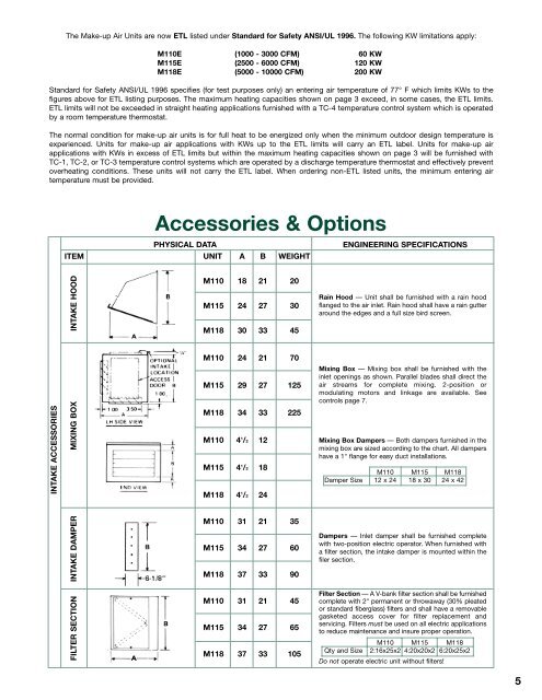
INTAKE ACCESSORIES<br />
ITEM<br />
INTAKE HOOD<br />
MIXING BOX<br />
INTAKE DAMPER<br />
FILTER SECTION<br />
Accessories & Options<br />
PHYSICAL DATA ENGINEERING SPECIFICATIONS<br />
UNIT A B WEIGHT<br />
M11018 21 20<br />
M115 24 27 30<br />
M118 3033 45<br />
M11024 21 70<br />
M115 29 27 125<br />
M118 34 33 225<br />
M1104 1 /2 12<br />
M115 4 1 /2 18<br />
M118 4 1 /2 24<br />
M11031 21 35<br />
M115 34 27 60<br />
M118 37 33 90<br />
M11031 21 45<br />
M115 34 27 65<br />
M118 37 33 105<br />
Rain Hood — Unit shall be furnished with a rain hood<br />
flanged to the air inlet. Rain hood shall have a rain gutter<br />
around the edges <strong>and</strong> a full size bird screen.<br />
Mixing Box — Mixing box shall be furnished with the<br />
inlet openings as shown. Parallel blades shall direct the<br />
air streams for complete mixing. 2-position or<br />
modulating motors <strong>and</strong> linkage are available. See<br />
controls page 7.<br />
Mixing Box Dampers — Both dampers furnished in the<br />
mixing box are sized according to the chart. All dampers<br />
have a 1" flange for easy duct installations.<br />
M110 M115 M118<br />
Damper Size 12 x 24 18 x 30 24 x 42<br />
Dampers — Inlet damper shall be furnished complete<br />
with two-position electric operator. When furnished with<br />
a filter section, the intake damper is mounted within the<br />
filer section.<br />
Filter Section — A V-bank filter section shall be furnished<br />
complete with 2" permanent or throwaway (30% pleated<br />
or st<strong>and</strong>ard fiberglass) filters <strong>and</strong> shall have a removable<br />
gasketed access cover for filter replacement <strong>and</strong><br />
servicing. Filters must be used on all electric applications<br />
to reduce maintenance <strong>and</strong> insure proper operation.<br />
M110 M115 M118<br />
Qty <strong>and</strong> Size 2:16x25x2 4:20x20x2 6:20x25x2<br />
Do not operate electric unit without filters!<br />
5