Electric Make-up Air, Space Heating and Ventilating Units - Brasch
Electric Make-up Air, Space Heating and Ventilating Units - Brasch
Electric Make-up Air, Space Heating and Ventilating Units - Brasch

Create successful ePaper yourself
Turn your PDF publications into a flip-book with our unique Google optimized e-Paper software.
BULLETIN A170-1<br />
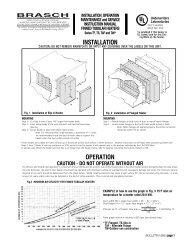
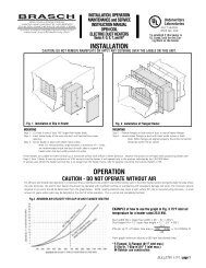
<strong>Electric</strong><br />
<strong>Make</strong>-<strong>up</strong> <strong>Air</strong>,<br />
<strong>Space</strong> <strong>Heating</strong><br />
<strong>and</strong> <strong>Ventilating</strong> <strong>Units</strong>
2<br />
NOTE: Selection of the proper unit, heating load <strong>and</strong> temperature control<br />
system is dependent on the application of the unit.<br />
A. <strong>Make</strong>-<strong>up</strong> <strong>Air</strong> Unit - used for heating 100% outside air to the indoor design<br />
temperature with discharge temperature of 70° F.<br />
B. <strong>Space</strong> <strong>Heating</strong> Unit - used for heating 100% return air from the<br />
conditioned space to make <strong>up</strong> for building heat loss only with a<br />
maximum discharge temperature of 120° F.<br />
C. Combination <strong>Make</strong>-<strong>up</strong> <strong>Air</strong> <strong>and</strong> <strong>Space</strong> <strong>Heating</strong> Unit - used to heat outside<br />
<strong>and</strong> return air combined through the mixing box option.<br />
D. Ventilation Unit - used to replace air exhausted from the space <strong>and</strong><br />
without heating capability.<br />
I. Determine <strong>Heating</strong> Load — KW<br />
A. <strong>Make</strong>-<strong>up</strong> <strong>Air</strong> Only — discharge temperature of 70° F. Use the following<br />
formula to compute the total KW needed when air volume (CFM) <strong>and</strong><br />
the indoor-outdoor design temperature difference (▲ T) are known:<br />
KW =<br />
CFM x ▲ T (° F) Note: Based on 0° F<br />
2745 entering air.<br />
B. <strong>Space</strong> <strong>Heating</strong> Only<br />
1. Calculate building design heat loss. Then,<br />
KW =<br />
BTUH<br />
3413<br />
2. Determine the minimum CFM required in order not to exceed 120° F<br />
discharge temperature:<br />
CFM =<br />
BTUH<br />
(120° F — indoor design temp) x 1.085<br />
C. Combined <strong>Make</strong>-<strong>up</strong> <strong>Air</strong> <strong>and</strong> <strong>Space</strong> <strong>Heating</strong> (heating <strong>and</strong> ventilating).<br />
The two KW’s found in A <strong>and</strong> B above may be added together,<br />
provided the following limitations are met:<br />
1. The make-<strong>up</strong> CFM must equal or exceed the value found in B-2.<br />
2. The total KW must not exceed the maximum value given in<br />
capacity table.<br />
Adjustment of the CFM, heating capacity or both may be required.<br />
Unit Selection<br />
Example<br />
How to Select The Unit<br />
II. Determine unit size <strong>and</strong> motor horsepower.<br />
A. Find the smallest applicable unit size from table for the required CFM<br />
<strong>and</strong> specified system static pressure.<br />
B. Add pressure drop for accessories <strong>and</strong> any external duct-work to<br />
obtain total system static pressure.<br />
C. Note motor horsepower for the unit selected, at the specified CFM<br />
<strong>and</strong> total system static pressure. If no motor horsepower is given in<br />
table for the specified system static pressure <strong>and</strong> CFM combination,<br />
check the next larger unit size.<br />
III.Select the Temperature Control System.<br />
A. Determine the number of temperature controller steps. Average<br />
temperature control is from 6 to 14° F rise per step. Finer or coarser<br />
control can be utilized.<br />
3160 x Total KW<br />
= Number of Controller Steps<br />
CFM x Degrees per step<br />
B. Select the type of control system desired.<br />
TC-1 1 to 14* step discharge temperature control for make-<strong>up</strong> air<br />
application where tamper-proof air temperature control is<br />
required.<br />
TC-2 1 to 14* step discharge temperature control for make-<strong>up</strong> air<br />
applications with a remote set point.<br />
TC-3 1 to 14* step discharge temperature control for make-<strong>up</strong> air <strong>and</strong><br />
space heating applications with remote set point <strong>and</strong> room<br />
thermostat.<br />
TC-4 1 to 14* step room temperature control for space heating<br />
applications.<br />
(* - Max. 13 steps on unit size M110)<br />
Given: Indoor design temperature 70° F<br />
Outdoor design temperature 0° F<br />
Desired ▲ t per step 10° F<br />
Building heat loss 200,000 BTUH<br />
<strong>Make</strong>-<strong>up</strong> <strong>Air</strong> CFM 4000<br />
External static pressure 0.5 in. W.C.<br />
<strong>Electric</strong>al power service 240 Volts, 3 Phase, 60 HZ<br />
I-A.<br />
Accessories: Rain hood, Permanent filters, inlet damper.<br />
4000 x 70 = 102.0 KW make-<strong>up</strong> air heating load.<br />
2745<br />
I-B. 200,000 = 58.6 KW space heating load.<br />
3413<br />
200,000<br />
(120-70) 1.085<br />
= 3686 CFM<br />
I-C. 4000 CFM O.K. (3686 CFM minimum)<br />
102.0 + 58.6 = 160.6 KW total heating load<br />
(170 KW allowed.)<br />
II-A. Select M115E unit.<br />
II-B. Total system static pressure = external + rain hood + filters<br />
+ inlet damper = .5 + .02 + .10 + .02 = 0.64 in W.C.<br />
II-C. 2 HP motor. (Note that 1 HP motor could have been used if no<br />
accessories had been specified.)<br />
III-A. 3160 x 160 = 12.6 Use 12 control steps.<br />
4000 x 10<br />
III-B. Select TC-3 temperature control system for make-<strong>up</strong> air <strong>and</strong><br />
space temperature controls.
M-110<br />
M-115<br />
M-118<br />
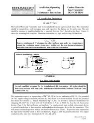
AIR CAPACITIES, PRESSURE DROP DATA-MAX. KW.<br />
CFM<br />
Outlet Motor Horsepower at System Static pressure of (Inches W.C.):<br />
Velocity 0.0 0.1 0.2 0.3 0.4 0.5 0.6 0.7 0.8 0.9 1.0 1.1 1.2<br />
1000 890 — — 1/2 1/2 1/2 1/2 1/2 1/2 1/2 — — — — .10 .12 .13<br />
1250 1110 — 1/2 1/2 1/2 1/2 1/2 1/2 1/2 1/2 1/2 1/2 — — .10 .17.18 .20<br />
1500 1340 1/2 1/2 1/2 1/2 1/2 1/2 1/2 1/2 1/2 1 1 1 1 .07.10 .25 .26 .28<br />
1750 1560 1/2 1/2 1/2 1/2 1/2 1/2 1/2 1 1 1 1 1 1 .15 0.10 .32 .34 .37<br />
2000 1780 1/2 1/2 1/2 1/2 1/2 1 1 1 1 1 1 1 1 61.2 61.2 61.2 N/A .10 .20 .15 0.02 0.02 .42 .44 .48<br />
2250 2000 1/2 1 1 1 1 1 1 1 1 1 1 1 1 .52 .55 .60<br />
2500 2230 1 1 1 1 1 1 1 1 1 1 1 1 — .15 .25 .20<br />
.64 .68 .74<br />
2750 2450 1 1 1 1 1 1 1 1 — — — — — .18 .30<br />
0.15 — — —<br />
3000 2670 1 1 1 1 — — — — — — — — — .20 .35 N/A — — —<br />
2500 1150 — — 1/2 1/2 1/2 1/2 1 1 1 1 — — — .16 .17.18<br />
2750 1260 — 1/2 1/2 1/2 1/2 1/2 1 1 1 1 1 1 — .10 .18 .20 .22<br />
3000 1380 — 1/2 1/2 1/2 1/2 1 1 1 1 1 1 1 1 .07.10 .22 .24 .26<br />
3250 1490 1/2 1/2 1/2 1/2 1 1 1 1 1 1 1 1 1 120.0 120.0 .26 .28 .30<br />
3500 1610 1/2 1/2 1 1 1 1 1 1 1 1 2 2 2 .15 0.10 .30 .32 .34<br />
3750 1720 1 1 1 1 1 1 1 1 2 2 2 2 2 .34 .37.40<br />
4000 1840 1 1 1 1 1 1 1 2 2 2 2 2 2 .8 .10 .15 .38 .40 .45<br />
4250 1950 1 1 1 1 1 2 2 2 2 2 2 2 2 120.0 @ 5000 .20 0.02 0.02 .44 .46 .50<br />
4500 2070 1 1 1 2 2 2 2 2 2 2 2 2 2 CFM .48 .52 .57<br />
4750 2180 1 2 2 2 2 2 2 2 2 2 2 2 — .15 .25 .55 .58 .63<br />
5000 2300 2 2 2 2 2 2 2 2 2 2 2 2 — 120.0 120.0 .20 .60 .63 .70<br />
5250 2410 2 2 2 2 2 2 2 2 2 2 2 — — .18 .30 0.15 .65 .68 .75<br />
5500 2530 2 2 2 2 2 2 2 2 2 — — — — .70 .75 —<br />
5750 2640 2 2 2 2 2 2 2 — — — — — — .20 .35 N/A — — —<br />
6000 2760 2 2 2 2 2 — — — — — — — — — — —<br />
5000 1660 — — — 1 1 1 2 2 2 2 2 2 2 .24 .26 .28<br />
5250 1740 — — 1 1 2 2 2 2 2 2 2 2 2 .10 .26 .28 .30<br />
5500 1830 — — 1 2 2 2 2 2 2 2 2 2 3 .28 .30 .33<br />
5750 1910 — — 2 2 2 2 2 2 2 2 2 3 3 178.8 189.7 .07.10 0.10 .30 .33 .35<br />
6000 1990 — 2 2 2 2 2 2 2 2 2 3 3 3 .33 .36 .38<br />
6250 2080 — 2 2 2 2 2 2 2 2 3 3 3 3 .37.39 .42<br />
6500 2160 2 2 2 2 2 2 2 2 3 3 3 3 3 .15 .40 .45 .46<br />
6750 2240 2 2 2 2 2 2 3 3 3 3 3 3 3 0.02 0.02 .42 .45 .48<br />
7000 2330 2 2 2 2 2 3 3 3 3 3 3 3 5 1.2 .45 .48 .52<br />
7250 2410 2 2 2 2 3 3 3 3 3 3 3 5 5 200.0 @ 8000 0.15 .48 .52 .57<br />
7500 2490 2 2 2 3 3 3 3 3 3 3 5 5 5 CFM .10 .15 .52 .55 .60<br />
7750 2570 2 2 3 3 3 3 3 3 3 5 5 5 5 .56 .60 .64<br />
8000 2660 3 3 3 3 3 3 3 5 5 5 5 5 5 .20 .60 .63 .68<br />
8250 2740 3 3 3 3 3 3 5 5 5 5 5 5 5 200.0 200.0 .63 .67.72<br />
8500 2820 3 3 3 3 3 5 5 5 5 5 5 5 5 .66 .70 .77<br />
8750 2910 3 3 3 5 5 5 5 5 5 5 5 5 — 0.20 .70 .73 .80<br />
9000 2990 3 3 5 5 5 5 5 5 5 5 5 5 — .15 .25 .74 .78 .84<br />
9250 3070 5 5 5 5 5 5 5 5 5 5 5 5 — .20 0.03 0.03 .77 .82 .88<br />
9500 3160 5 5 5 5 5 5 5 5 5 5 5 — — .80 .86 .93<br />
9750 3240 5 5 5 5 5 5 5 5 5 5 — — — .18 .30 0.25 .86 .90 —<br />
10000 3320 5 5 5 5 5 5 5 5 — — — — — — — —<br />
NOTE: <strong>Air</strong> Volume <strong>and</strong> <strong>Heating</strong> Capacities are good <strong>up</strong> to 1000 ft. elevation.<br />
Consult <strong>Brasch</strong> Factory for higher altitudes.<br />
LEGEND<br />
BM Blower Motor<br />
MS Motor Starter<br />
MF Motor Fuses<br />
ID Interlocking Disconnect<br />
(Unfused)<br />
GS Ground Screw<br />
SV S<strong>up</strong>ply Voltage (Fused)<br />
HC <strong>Heating</strong> Coils<br />
HF Heater Fuses<br />
HL Heater Limiters<br />
IT Inlet Thermostat<br />
OC Operating Contactor<br />
CT Control Transformer<br />
DM Damper Motor (Inlet)<br />
ES End Switch<br />
DT Discharge Thermostat<br />
AF <strong>Air</strong> Flow Switch<br />
AR Automatic Reset<br />
ST <strong>Space</strong> Thermostat<br />
HS Heat Switch (On-Off)<br />
FS Fan Switch (On-Off)<br />
FO Fan On Pilot Light<br />
HO Heat On Pilot Light<br />
___ Factory Wired<br />
- - - Field Wired<br />
Maximum <strong>Heating</strong><br />
Capacity-KW<br />
(See I-C under selection)<br />
208 240 480<br />
Unit <strong>Electric</strong>al Information<br />
Linear<br />
Slot<br />
Diffuser<br />
<strong>Brasch</strong> offers a variety of control options utilizing discharge, room <strong>and</strong> inlet thermostats<br />
<strong>and</strong> fast response electronic step controllers for <strong>up</strong> to 14 steps of heat control.<br />
Cleanable<br />
Type<br />
Pressure Drop Data<br />
Filters<br />
Rain Hood<br />
Throwaway Inlet<br />
Std. Dampers<br />
<strong>and</strong> Inlet<br />
30%<br />
Pleated<br />
Fiberglass<br />
Screen<br />
Discharge Louvers<br />
Discharge<br />
Elbow 0° 221 /2° 45°<br />
3
4<br />
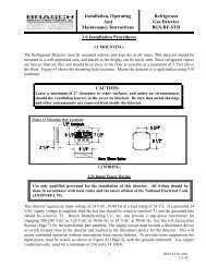
E (<strong>Electric</strong>) & V (Ventilation) DIMENSIONS<br />
A B C D E F G H J WEIGHT<br />
M110 48 21 30 19 28 11-7/8 13-5/8 8-3/16 13 300<br />
M115 58 27 42 25 40 16-3/8 19-1/8 11-7/16 13 475<br />
M118 6733 51 31 49 19-3/8 22-3/8 14-5/16 13 725<br />
DO NOT USE THESE DIMENSIONS FOR CONSTRUCTION PURPOSES.<br />
REQUEST CERTIFIED PRINTS FROM FACTORY.<br />
Sample Engineering Specifications<br />
GENERAL: Furnish <strong>and</strong> install BRASCH ETL listed units(s) where<br />
indicated on the plans, Series M _______ E (electric air heater) or V<br />
(ventilation air h<strong>and</strong>ler) as manufactured by <strong>Brasch</strong> Manufacturing<br />
Co. of Maryl<strong>and</strong> Heights, Missouri. Unit(s) shall be factory run <strong>and</strong><br />
tested in order to assure proper assembly <strong>and</strong> performance of<br />
controls <strong>and</strong> other components.<br />
INSTALLATION, wiring, adjustment <strong>and</strong> start-<strong>up</strong> shall be in<br />
accordance with the manufacturer’s installation <strong>and</strong> operation<br />
manual provided with each unit. Unit(s) shall be installed as<br />
indicated on plans.<br />
CONSTRUCTION of the unit shall include a unitary steel frame, <strong>and</strong><br />
a corrosion resistant, zinc-coated <strong>and</strong> bonderized steel casing with<br />
a finish coat of high-build industrial grade enamel. Finish color shall<br />
be gray. Unit shall have a service panel for access to an internally<br />
mounted motor, fan drive <strong>and</strong> temperature controller. Shall be<br />
suitable for indoor (outdoor) installation. The interior of the unit shall<br />
be insulated with 1" thick fiberglass, 1 1 /2 lb. per cubic foot density<br />
per NFPA-90. The fan shall discharge horizontally into a full size<br />
internal static regain duct section. A protective screen shall be<br />
provided on the inlet.<br />
BLOWER shall be a double width-double inlet (DWDI), forwardcurved,<br />
centrifugal fan, with a steel wheel <strong>and</strong> housing. Fan shall be<br />
arranged for draw-through operation, <strong>and</strong> wheel shall be statically<br />
<strong>and</strong> dynamically balanced. Fan speed shall be at least 25% below<br />
the first critical speed for the shaft. Fan shaft bearings shall be<br />
permanently lubricated, self-aligning sealed ball bearings, rubbermounted<br />
for sound <strong>and</strong> vibration attenuation.<br />
FAN DRIVE shall be a heavy duty V-belt type designed for a 1.5<br />
minimum service factor based on motor horsepower. Adjustable (or)<br />
Fixed pitch motor sheave shall be set for the air delivery <strong>and</strong> total<br />
system static pressure shown on the plans.<br />
BASIC UNIT<br />
MOTOR shall be a ball bearing type, designed for continuous duty<br />
at the specified voltage. Motor shall be mounted on an adjustable<br />
sliding base located out of the heated airstream. Motor shall be<br />
controlled by a magnetic motor contactor with overload protection<br />
provided in each leg <strong>and</strong> shall have motor fusing as required by<br />
NEC.<br />
ELECTRIC HEATER wattage, voltage, <strong>and</strong> number of steps shall<br />
be shown on plans or as required to meet the National <strong>Electric</strong><br />
Code. (Three phase heaters shall have balanced three phase steps.)<br />
Heater shall be slip-in type with an externally accessible control<br />
panel. Heater coils shall be open type, made of nickel-chromium<br />
(80-20), <strong>and</strong> shall be positioned by ceramic bushings in a<br />
galvanized steel frame. Power terminals shall be suitable for copper<br />
conductors <strong>and</strong> arranged for single s<strong>up</strong>ply. Coil terminals shall be<br />
stainless steel with ceramic insulators, <strong>and</strong> shall be recessed so<br />
that heating elements <strong>and</strong> safety controls are entirely in the air<br />
stream. Heater shall have a protective screen on the inlet side.<br />
(Delete electric heater section on ventilation units.)<br />
CONTROL COMPONENTS located in the heater panel shall<br />
include disconnecting break magnetic contactors, motor starter,<br />
motor fuses, control transformer <strong>and</strong> s<strong>up</strong>plementary circuit fuses<br />
per NEC. Other components shall include differential pressure type<br />
air flow switch, high temperature limit, thermal cut-out <strong>and</strong><br />
temperature controller suitable for the control mode specified. (Add<br />
other applicable electrical options.) External control wiring<br />
connections shall be made at a terminal strip with marked<br />
terminals, located in the heater panel.<br />
(Delete control components section on ventilation units.)<br />
OPTIONS AND ACCESSORIES shall be provided as listed below<br />
(from pages 5, 6 <strong>and</strong> 7):
The <strong>Make</strong>-<strong>up</strong> <strong>Air</strong> <strong>Units</strong> are now ETL listed under St<strong>and</strong>ard for Safety ANSI/UL 1996. The following KW limitations apply:<br />
M110E (1000 - 3000 CFM) 60 KW<br />
M115E (2500 - 6000 CFM) 120 KW<br />
M118E (5000 - 10000 CFM) 200 KW<br />
St<strong>and</strong>ard for Safety ANSI/UL 1996 specifies (for test purposes only) an entering air temperature of 77° F which limits KWs to the<br />
figures above for ETL listing purposes. The maximum heating capacities shown on page 3 exceed, in some cases, the ETL limits.<br />
ETL limits will not be exceeded in straight heating applications furnished with a TC-4 temperature control system which is operated<br />
by a room temperature thermostat.<br />
The normal condition for make-<strong>up</strong> air units is for full heat to be energized only when the minimum outdoor design temperature is<br />
experienced. <strong>Units</strong> for make-<strong>up</strong> air applications with KWs <strong>up</strong> to the ETL limits will carry an ETL label. <strong>Units</strong> for make-<strong>up</strong> air<br />
applications with KWs in excess of ETL limits but within the maximum heating capacities shown on page 3 will be furnished with<br />
TC-1, TC-2, or TC-3 temperature control systems which are operated by a discharge temperature thermostat <strong>and</strong> effectively prevent<br />
overheating conditions. These units will not carry the ETL label. When ordering non-ETL listed units, the minimum entering air<br />
temperature must be provided.<br />
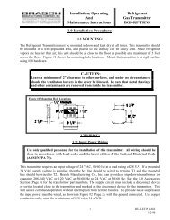
INTAKE ACCESSORIES<br />
ITEM<br />
INTAKE HOOD<br />
MIXING BOX<br />
INTAKE DAMPER<br />
FILTER SECTION<br />
Accessories & Options<br />
PHYSICAL DATA ENGINEERING SPECIFICATIONS<br />
UNIT A B WEIGHT<br />
M11018 21 20<br />
M115 24 27 30<br />
M118 3033 45<br />
M11024 21 70<br />
M115 29 27 125<br />
M118 34 33 225<br />
M1104 1 /2 12<br />
M115 4 1 /2 18<br />
M118 4 1 /2 24<br />
M11031 21 35<br />
M115 34 27 60<br />
M118 37 33 90<br />
M11031 21 45<br />
M115 34 27 65<br />
M118 37 33 105<br />
Rain Hood — Unit shall be furnished with a rain hood<br />
flanged to the air inlet. Rain hood shall have a rain gutter<br />
around the edges <strong>and</strong> a full size bird screen.<br />
Mixing Box — Mixing box shall be furnished with the<br />
inlet openings as shown. Parallel blades shall direct the<br />
air streams for complete mixing. 2-position or<br />
modulating motors <strong>and</strong> linkage are available. See<br />
controls page 7.<br />
Mixing Box Dampers — Both dampers furnished in the<br />
mixing box are sized according to the chart. All dampers<br />
have a 1" flange for easy duct installations.<br />
M110 M115 M118<br />
Damper Size 12 x 24 18 x 30 24 x 42<br />
Dampers — Inlet damper shall be furnished complete<br />
with two-position electric operator. When furnished with<br />
a filter section, the intake damper is mounted within the<br />
filer section.<br />
Filter Section — A V-bank filter section shall be furnished<br />
complete with 2" permanent or throwaway (30% pleated<br />
or st<strong>and</strong>ard fiberglass) filters <strong>and</strong> shall have a removable<br />
gasketed access cover for filter replacement <strong>and</strong><br />
servicing. Filters must be used on all electric applications<br />
to reduce maintenance <strong>and</strong> insure proper operation.<br />
M110 M115 M118<br />
Qty <strong>and</strong> Size 2:16x25x2 4:20x20x2 6:20x25x2<br />
Do not operate electric unit without filters!<br />
5
6<br />
MOUNTING ACCESSORIES<br />
DISCHARGE ACCESSORIES<br />
ITEM<br />
MOUNTING STANDS<br />
ROOF CURB<br />
DT DOWNTURN<br />
DTL DOWNTURN<br />
LSD-1<br />
DISCHARGE LOUVER<br />
Accessories & Options (Continued)<br />
PHYSICAL DATA ENGINEERING SPECIFICATIONS<br />
UNIT A B WEIGHT<br />
VIBRATION ISOLATORS<br />
M11025 1 /2 41 27<br />
M115 28 1 /2 51 27<br />
M118 31 1 /2 6027<br />
M11021 3 /4 21 3 /4 35<br />
M115 27 3 /4 27 3 /4 45<br />
M118 29 3 /4 29 3 /4 60<br />
M11011 7 /8 13 7 /8 15<br />
M115 16 3 /8 18 3 /8 20<br />
M118 19 3 /8 21 3 /8 30<br />
M11018 18 25<br />
M115 24 24 35<br />
M118 26 3050<br />
M115<br />
& 95 23 1 /2 37<br />
M118<br />
Only<br />
M11021 19 30<br />
M115 27 25 50<br />
M118 33 31 95<br />
Mounting St<strong>and</strong>s — Mounting st<strong>and</strong>s shall be<br />
s<strong>up</strong>plied by the manufacturer for elevating the unit<br />
above the mounting surface, <strong>and</strong> shall be set on<br />
pads (or) rails at least 1 1 /2" thick, furnished by the<br />
contractor, to give a 12" minimum height for roof<br />
mounting. 4 legs or 6 legs required.<br />
Roof Curb for 90° Downturn — Type DTL — A<br />
14" high insulated roof curb shall be shipped<br />
separately for mounting by the contractor directly<br />
to the roof deck. Included with the curb shall be a<br />
1 1 /2" nailing strip.<br />
1) 4 or 6 Required 2) Spring or Rubber-in-shear<br />
3) Suspended or Base Mounted<br />
Discharge Elbow — A 90° miter elbow with<br />
turning vanes shall be furnished for direct<br />
attachment to the unit discharge collar.<br />
Discharge Downturn — A 90° miter elbow with<br />
turning vanes shall be furnished for direct<br />
attachment to the unit discharge collar. Used for<br />
outdoor installation with roof curb. Elbow shall<br />
have an integral counter-flashing to fit directly to<br />
the roof curb. See page 5 for roof curb<br />
dimensions. (For “G” refer to page 4).<br />
Linear Slot Diffuser — LSD-1 center inlet with<br />
2-5/8" x 94" slot; use with M115 to deliver 5000<br />
CFM @ 0.8" W.C. @ 2900 FPM velocity. Use with<br />
M118 to deliver 8000 CFM @ 1.2" W.C. @ 4700<br />
FPM velocity. These units form thermal air curtains<br />
for entrances. Use with DTS Special Downturn.<br />
Discharge Louver — A discharge louver, the full<br />
width of the unit shall be mounted to a plenum at<br />
the discharge end, <strong>and</strong> shall have dual deflection<br />
vanes for both horizontal <strong>and</strong> vertical adjustment<br />
of the discharge air stream.
ELECTRICAL OPTIONS:<br />
Accessories & Options (Continued)<br />
Temperature Controls<br />
See Page 2 for detailed Explanation<br />
Exhaust Fan Interlock<br />
Kitchen Ventilation System Control<br />
Low Temperature Cutout<br />
Clogged Filter Switch & Light<br />
Mixing Box Controls<br />
SCR CONTROLLER:<br />
PNEUMATIC OPTIONS:<br />
TC-1<br />
TC-2<br />
TC-3<br />
TC-4<br />
RCS<br />
NSB<br />
EFI<br />
KVSC<br />
LTC<br />
CF<br />
Two<br />
Position<br />
Discharge<br />
Manual<br />
The st<strong>and</strong>ard <strong>Brasch</strong> temperature control systems are<br />
100% thermostatic control for the tightest, most reliable,<br />
<strong>and</strong> most economical control available in electric forced<br />
air heating.<br />
Remote control station with blower on/off switch, heater<br />
on/off switch <strong>and</strong> indicating lights. Includes field terminals<br />
for field wiring of operating device.<br />
Night setback automatically reduces space temperature<br />
at night <strong>and</strong> on weekends to decrease heating costs. NSB<br />
is a factory assembly including 24-hr. time clock with<br />
skip-a-day feature, night stat, timer override <strong>and</strong> terminals<br />
for field wiring, all in a lockable cabinet.<br />
Provides an auxiliary contact on motor starter to energize<br />
exhaust fan starter by others.<br />
Provides second motor starter with overload protection<br />
<strong>and</strong> motor fusing for starting of exhaust fan. Factory wired<br />
in base unit.<br />
Low temperature cutout incorporates a thermostat <strong>and</strong><br />
time delay relay in a control arrangement designed to<br />
guarantee against cold air discharge.<br />
Clogged filter indicating light located in remote control<br />
station <strong>and</strong> operated by pressure differential type air flow<br />
switch.<br />
Includes a two position damper motor factory wired <strong>and</strong><br />
mounted to provide 100% make-<strong>up</strong> air or 100% return air.<br />
No field installation necessary.<br />
Provides a modulating damper motor <strong>and</strong> a thermostat<br />
located to maintain a constant temperature at the discharge<br />
of the mixing box while maintaining constant air flow.<br />
Provides manual operation of dampers with locking<br />
quadrants.<br />
Consult Factory<br />
Consult Factory<br />
7
The following information must appear in the job or ordering specifications<br />
to verify selections <strong>and</strong> process orders for Series M110, M115 or M118 electric air heaters:<br />
11880 Dorsett Rd.<br />
Maryl<strong>and</strong> Heights, Missouri 63043<br />
314.291.0440 • Fax 314.291.0646<br />
e-mail braschmfg@braschmfg.com<br />
www.braschmfg.com<br />
©<strong>Brasch</strong> Manufacturing Company, Inc.<br />
Limited Warranty<br />
<strong>Brasch</strong> Manufacturing Company, Inc. warrants heater resistance<br />
coils against defects in material <strong>and</strong> workmanship for a period of<br />
two years from date of shipment. Other components <strong>and</strong><br />
accessories are guaranteed for a period of one year from date of<br />
shipment against defects in material or workmanship. Should<br />
evidence of defects in material or workmanship occur during the<br />
warranty period, <strong>Brasch</strong> Manufacturing Company, Inc. will repair<br />
or replace the product at its own discretion without charge.<br />
<strong>Brasch</strong> Manufacturing Company, Inc. shall not be held<br />
responsible for any charges in connection with the removal or<br />
replacement of allegedly defective equipment, nor for incidental<br />
or consequential damage.