

Product Data - Carrier
Product Data - Carrier
Product Data - Carrier

Create successful ePaper yourself
Turn your PDF publications into a flip-book with our unique Google optimized e-Paper software.
48TJ008-014<br />
<strong>Product</strong><br />
<strong>Data</strong><br />
48TJ024,028<br />
48TJ004-007<br />
48TJ016,020<br />
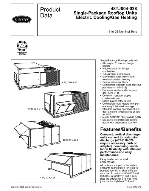
48TJ004-028<br />
Single-Package Rooftop Units<br />
Electric Cooling/Gas Heating<br />
3 to 25 Nominal Tons<br />
Single-Package Rooftop Units with:<br />
• Alumagard heat exchanger<br />
coating<br />
• Induced-draft fan for gas<br />
combustion<br />
• Tubular heat exchangers<br />
• Galvanized steel cabinet with<br />
weather-resistant coating<br />
• Two-in. return-air filters<br />
• Commercial strength base rails (full<br />
perimeter on 004-014)<br />
• Exclusive tool-less filter access<br />
door (004-014)<br />
• Corrosion-resistant sloped<br />
condensate pan<br />
• Single power entry to unit<br />
• Commercial duty motors with permanently<br />
lubricated bearings<br />
• Standard cooling operation at outdoor<br />
ambient temperatures as low<br />
as 25 F<br />
• Meets ASHRAE Standard 62 (IAQ)<br />
• Exclusive integrated gas control<br />
board with diagnostics (004-014)<br />
Features/Benefits<br />
Compact, vertical discharge<br />
units convert to horizontal<br />
discharge (48TJ016-028<br />
require accessory curb or<br />
adapter), combining installation<br />
flexibility with efficient<br />
performance and easy<br />
maintenance.<br />
Easy installation and<br />
conversion<br />
All units are shipped in the vertical<br />
discharge configuration for fit-up to<br />
standard roof curbs. (Two different<br />
curb sizes fit unit sizes 004-007 and<br />
008-014, respectively, and 2 curb<br />
sizes are offered for 016-028 units<br />
[one size for high-heat 024 and<br />
Copyright 1996 <strong>Carrier</strong> Corporation Form 48TJ-5PD
028 units, and one size for all others].)<br />
The contractor can order and<br />
install the roof curb early in the construction<br />
stage, before decisions on<br />
size requirements are made.<br />
All units feature roll-formed baserail<br />
design with forklift slots on 3 sides<br />
and rigging holes for easier maneuvering.<br />
The standard 48TJ004-006<br />
units have operating weights under<br />
500 lb and durable packaging<br />
protects all units during shipment<br />
and storage.<br />
The units can be easily converted<br />
from a vertical to a horizontal discharge<br />
configuration either by interchanging<br />
the panels supplied with the<br />
unit (004-014) or by using one of<br />
the horizontal supply/return curbs or<br />
the horizontal adapter (016-028).<br />
Convenient duct openings in the<br />
48TJ016-028 unit basepans permit<br />
side-by-side or concentric duct connections<br />
(see Application data section on<br />
page 64) without requiring internal<br />
unit modification.<br />
The non-corrosive sloped condensate<br />
pan permits either an external<br />
horizontal side condensate drain (outside<br />
the roof curb) or an internal<br />
vertical bottom drain (inside the roof<br />
curb). Both options require an external,<br />
field-supplied P-trap. Also, the condenser<br />
coil grille (available on the<br />
004-014 units as a field-installed accessory<br />
or a factory-installed option)<br />
provides a metal plate as an alternate<br />
location for the field-supplied disconnect,<br />
if desired.<br />
The 48TJ units were designed with<br />
service technicians in mind. The<br />
single-row condenser coils on the<br />
48TJ004-006 and 008 units simplify<br />
the cleaning process. The efficient<br />
in-shot burners and all ignition components<br />
are contained in an easily<br />
removable, compact assembly.<br />
The 48TJ004-014 units also have<br />
a standard filter access panel, which<br />
permits tool-less filter changes, even<br />
on units with horizontal economizers.<br />
Integrated gas unit controller<br />
(IGC) (004-014 only)<br />
All ignition components are contained<br />
in the compact IGC which is easily<br />
accessible for servicing. The IGC control<br />
board, designed and manufactured<br />
exclusively for <strong>Carrier</strong> rooftop<br />
units, provides built-in diagnostic<br />
capability. An LED (light-emitting diode)<br />
simplifies troubleshooting by<br />
2<br />
providing visual fault notification and<br />
system status confirmation.<br />
The IGC also contains an exclusive<br />
anti-cycle protection for gas heat<br />
operation. After 4 continuous cycles<br />
on the unit high-temperature limit<br />
switch, the gas heat operation is disabled,<br />
and an error code is issued.<br />
This feature greatly improves reliability<br />
of the rooftop unit.<br />
The IGC also contains burner control<br />
logic for accurate and dependable<br />
gas ignition. The LED is visible<br />
without removing the unit control box<br />
access panel. This LED faultnotification<br />
system reduces service<br />
person troubleshooting time and minimizes<br />
service costs. The IGC also<br />
maximizes heating efficiency by controlling<br />
evaporator-fan on and off<br />
delays.<br />
Simple electrical connections<br />
Terminal boards, located in the base<br />
unit control box, facilitate connections<br />
to room thermostat, outdoor thermostat(s),<br />
and economizer. Service<br />
panels are quickly removed, permitting<br />
easy servicing.<br />
Thru-the-bottom service connection<br />
capability (004-014) and thru-thecurb<br />
service connections (016-028)<br />
allow power and control wiring to<br />
be routed through unit basepan<br />
(004-014 units) or curb (016-028<br />
units), minimizing roof penetrations.<br />
Both power and control connections<br />
are made on the same side of<br />
the unit to simplify installation.<br />
In addition, color-coded wires permit<br />
easy tracing and diagnostics.<br />
Table of contents<br />
Proven compressor reliability<br />
Design techniques feature computerprogrammed<br />
balance between<br />
compressor, condenser, and evaporator.<br />
<strong>Carrier</strong>-specified hermetic<br />
(004-014 units) and semi-hermetic<br />
(016-028 units) compressors are<br />
equipped with compressor overcurrent<br />
and overtemperature protection to<br />
ensure dependability. Crankcase heaters<br />
(016-028 units) prevent refrigerant<br />
dilution of oil during off cycles and<br />
ensure proper lubrication at start-up<br />
to prolong compressor life. Crankcase<br />
heaters are not necessary on 004-<br />
014 units due to high-side crankcase<br />
design (007,014) and low refrigerant<br />
charge levels (004-014).<br />
The 48TJ016 unit (with factorysupplied<br />
unloading) is equipped with a<br />
thermostatic expansion valve to precisely<br />
adjust refrigerant flow during<br />
Stage 1 (unloaded) operation. All<br />
other 48TJ units have <strong>Carrier</strong>’s exclusive<br />
Acutrol metering device which<br />
precisely controls refrigerant flow,<br />
preventing slugging and flood-back,<br />
while maintaining optimum unit<br />
performance.<br />
Durable, dependable<br />
construction<br />
Designed for durability in any<br />
climate, the weather-resistant cabinets<br />
are constructed of galvanized<br />
steel and bonderized, and all exterior<br />
panels are coated with a prepainted<br />
baked enamel finish. The paint finish<br />
is non-chalking, and is capable of<br />
withstanding Federal test method<br />
Standard No. 141 (Method 6061)<br />
500-hour salt spray test. All internal<br />
Page<br />
Features/Benefits .........................................1-4<br />
Model Number Nomenclature .................................4<br />
ARI Capacity Ratings. ......................................5,6<br />
Physical <strong>Data</strong> ...........................................7-12<br />
Options and Accessories ...................................13-15<br />
Base Unit Dimensions ....................................16-20<br />
Accessory Dimensions ....................................21-24<br />
Selection Procedure ........................................24<br />
Performance <strong>Data</strong> .......................................25-52<br />
Electrical <strong>Data</strong> ..........................................53,54<br />
Typical Piping and Wiring ..................................55,56<br />
Typical Wiring Schematics .................................57,58<br />
Controls ..............................................59-63<br />
Application <strong>Data</strong> ........................................64,65<br />
Guide Specifications ......................................66-72
Features/Benefits (cont)<br />
cabinet panels are primed, permitting<br />
longer life and a more attractive<br />
appearance for the entire unit.<br />
In addition, the 48TJ008-014 units<br />
are designed with a single, continuous<br />
top piece to eliminate any possible<br />
leaks. Totally-enclosed condenser-fan<br />
motors and permanently-lubricated<br />
bearings provide additional unit<br />
dependability.<br />
Integrated economizers and<br />
outdoor air<br />
During a first stage call for cooling, if<br />
the outdoor-air temperature is below<br />
the control changeover set point,<br />
the discharge-air sensor modulates<br />
the economizer outdoor-air damper<br />
open to achieve the changeover set<br />
point. When second-stage cooling<br />
is called for, the compressor is energized<br />
in addition to the economizer. If<br />
the outdoor-air temperature is above<br />
the changeover set point, the first<br />
stage of compression is activated and<br />
the economizer stays at vent position.<br />
Economizer operation is<br />
controlled by Accusensor I dry-bulb<br />
thermostat that senses outdoor-air<br />
temperature. Accessory upgrade kits<br />
include Accusensor II solid-state<br />
enthalpy control (004-014) and Accusensor<br />
III enthalpy sensor.<br />
The Durablade economizer (option<br />
or accessory) on the 48TJ004-014<br />
units has a reliable sliding plate damper<br />
which is easily adjusted for 100%<br />
outdoor air, 100% return air, or any<br />
proportions of mixed air.<br />
The 48TJ004-014 units can also<br />
utilize the optional Parablade<br />
economizer. This economizer incorporates<br />
a parallel-opposed blade design<br />
with standard enthalpy controls. In<br />
addition, the Parablade economizer<br />
has a spring return built into the<br />
damper motor to provide reliable closeon-power-loss.<br />
The Parablade economizer<br />
comes equipped with up to<br />
45% barometric relief capability for<br />
high outdoor airflow applications.<br />
For units without economizer, yearround<br />
ventilation is enhanced by a<br />
manual outdoor-air damper (ordered<br />
as standard on 48TJ016-028; ordered<br />
as an accessory or an option on<br />
48TJ004-014 units). The damper can<br />
be preset to admit up to 25% outdoor<br />
air (016-028) or 50% outdoor<br />
air (004-014).<br />
In addition, the barometric relief<br />
damper or power exhaust accessory<br />
can be utilized to help maintain proper<br />
building pressure.<br />
Quiet, efficient operation and<br />
dependable performance<br />
Compressors have vibration isolators<br />
for extremely quiet operation. Efficient<br />
fan and motor design permits operation<br />
at very low sound levels and all<br />
48TJ004-014 units are mounted<br />
on independent mounting rails.<br />
The 48TJ008-028 units offer high<br />
energy efficiency and lower utility<br />
costs through part-load operation using<br />
2 stages of cooling.<br />
Quiet and efficient operation is provided<br />
by belt-driven evaporator fans<br />
(standard on all units over 5 tons).<br />
The belt-driven evaporator-fan with<br />
variable-pitch pulleys allows adjustment<br />
to available static pressure to meet<br />
the job requirements of even the most<br />
demanding applications.<br />
Increased operating efficiency is<br />
achieved through computer-designed<br />
coils featuring staggered copper tubes.<br />
Fins are ripple-edged for strength,<br />
lanced, and double waved for higher<br />
heat transfer.<br />
Tubular, dimpled (004-014 units)<br />
gas heat exchangers optimize heat<br />
transfer for improved efficiency. The<br />
tubular design permits hot gases to<br />
make multiple passes across the path<br />
of the supply air. The dimpled design<br />
(004-014 units) creates a turbulent<br />
gas flow to maximize heating<br />
efficiency. The extra thick Alumagard<br />
heat exchanger coating provides corrosion<br />
resistance and ensures long life.<br />
The unsightly appearance of flue<br />
stacks is eliminated and the effects of<br />
wind on heating operations are diminished<br />
by the induced draft combustion<br />
system. The inducer fan draws<br />
hot combustion gas through the heat<br />
exchanger at the optimum rate for the<br />
most effective heat transfer. The heat<br />
exchanger operates under negative<br />
pressure, preventing flue gas leakage<br />
into the indoor supply air.<br />
During the heating mode, the<br />
evaporator-fan relay automatically<br />
starts the evaporator fan after the<br />
heat exchanger warms up to a suitable<br />
temperature. This prevents cold<br />
air from entering the supply duct system<br />
when the conditioned space is<br />
calling for heat to maximize efficiency.<br />
On the 48TJ004-014 units, the<br />
direct-spark ignition system saves<br />
operating expense when compared to<br />
pilot ignition systems. No crossover<br />
tube is required, therefore no sooting<br />
or pilot fouling problems can occur.<br />
All 48TJ standard units are designed<br />
for natural gas, but an accessory LP<br />
(liquid propane) conversion kit is available<br />
for the if required.<br />
Safety is built in<br />
The 48TJ016-028 units have an<br />
intermittent pilot ignition. Runaway<br />
gas conditions are prevented and safe<br />
operation is guaranteed. The pilot<br />
flame is proven at the burner farthest<br />
from the ignition source, instead of<br />
at the ignition source itself. The main<br />
gas valve will not open if the pilot<br />
flame malfunctions and fails to reach<br />
the sensor.<br />
All 48TJ units have a flame rectification<br />
sensor to quickly sense the<br />
burner (48TJ004-014) or pilot<br />
(48TJ016-028) flame and ignite burners<br />
almost immediately. Fast shutdown<br />
is a certainty since the sensor<br />
reacts quickly to any flame outage or<br />
system failure. In the event of a<br />
shutdown, an error code is issued at<br />
the IGC board (004-014).<br />
Safety is also assured due to the<br />
heating safety controls which will shut<br />
down the unit if there is a problem.<br />
If excessive temperatures develop,<br />
limit switches shut off the gas valve.<br />
After 4 continuous short cycles of the<br />
high-temperature limit switch, the<br />
IGC board locks out the gas heat<br />
cycle to prevent any further short<br />
cycles (004-014). This safety feature is<br />
provided exclusively on <strong>Carrier</strong> rooftop<br />
units. The rollout switch also<br />
deenergizes the gas valve in the event<br />
of a flame rollout. On the 48TJ016-<br />
028 units, the pressure switch shuts<br />
down the main gas valve in case of<br />
insufficient combustion air.<br />
3
Features/Benefits (cont)<br />
<strong>Carrier</strong> Apollo controls add<br />
reliability, efficiency, and<br />
simplification<br />
The Apollo direct digital controls are<br />
ordered as a factory-installed option.<br />
Designed and manufactured<br />
exclusively by <strong>Carrier</strong>, the controls can<br />
be used to actively monitor and control<br />
all modes of operation, as well<br />
as to monitor evaporator-fan status,<br />
filter status, indoor-air quality (humidity<br />
and carbon dioxide), supply-air<br />
temperature, and outdoor-air<br />
temperature.<br />
The Apollo communicating controls<br />
are factory-installed into the rooftop<br />
unit control box, and come equipped<br />
with built-in diagnostic capabilities.<br />
Light-emitting diodes (LEDs) simplify<br />
troubleshooting by indicating thermostat<br />
commands for both stages of<br />
heating and cooling, evaporator fan<br />
operation, and economizer operation.<br />
The Apollo communicating controls<br />
are designed to work specifically with<br />
the <strong>Carrier</strong> TEMP and VVT (variable<br />
volume and temperature) thermostats.<br />
The Apollo controls, combined<br />
with <strong>Carrier</strong> thermostats, incorporate<br />
a 5-minute recycle delay timer<br />
between modes of operation to prevent<br />
short cycling.<br />
The standard rooftop control<br />
system is readily adaptable to all conventional<br />
and programmable thermostats.<br />
In addition, units are suitable<br />
for integration into building monitor<br />
control systems if required. This system<br />
gives the 48TJ units the flexibility to<br />
communicate with almost any thermostat<br />
or building control system.<br />
Model number nomenclature<br />
LEGEND<br />
Al — Aluminum<br />
Cu — Copper<br />
FIOP — Factory-Installed Option<br />
4<br />
SIZES 004-014<br />
*Refer to 48TJ Price Pages for 48TJ FIOP code table or<br />
contact your local representative for more details.<br />
†Single phase is available on 5-ton and smaller units.<br />
Indoor-air quality begins with<br />
<strong>Carrier</strong> rooftops<br />
Sloped condensate pans minimize biological<br />
growth in rooftop units in<br />
accordance with ASHRAE (American<br />
Society of Heating, Refrigeration,<br />
and Air Conditioning Engineers) Standard<br />
62. Two-in. filters with optional<br />
dirty filter indicator switch provide for<br />
greater particle reduction in the return<br />
air. The face-split evaporator<br />
coils improve the dehumidification capability<br />
of standard units, and standard<br />
enthalpy controls provided with<br />
the optional or accessory (004-014)<br />
economizers maximize building humidity<br />
control. The 48TJ004-014 units<br />
also have an accessory, 100% open,<br />
two-position damper to meet all<br />
your fresh outdoor air requirements.<br />
SIZES 016-028
ARI* capacity ratings<br />
UNIT 48TJ<br />
NOMINAL<br />
TONS<br />
STANDARD<br />
CFM<br />
NET COOLING<br />
CAPACITY<br />
(Btuh)<br />
TOTAL<br />
kW<br />
SEER†<br />
Belt Drive Direct Drive<br />
EER<br />
SOUND<br />
RATING<br />
(Bels)<br />
004 3 1200 35,000 4.0 10.0 9.7 8.7 8.2<br />
005 4 1600 47,000 5.5 10.0 9.7 8.6 8.2<br />
006 5 2000 57,000 6.7 10.0 9.7 8.5 8.2<br />
UNIT 48TJ<br />
NOMINAL<br />
TONS<br />
STANDARD<br />
CFM<br />
NET COOLING<br />
CAPACITY<br />
(Btuh)<br />
TOTAL<br />
kW<br />
EER<br />
SOUND<br />
RATING<br />
(Bels)<br />
007 6 2100 70,000 7.9 8.9 8.4 **<br />
008 7 1 ⁄ 2 2800 85,000 9.6 8.9 8.6 9.35<br />
009 8 1 ⁄ 2 3000 99,000 11.0 9.0 8.6 9.00<br />
012 10 4000 117,000 13.0 9.0 8.8 9.35<br />
014 12 1 ⁄ 2 4500 145,000 15.8 9.2 8.8 9.65<br />
016 15 5250 178,000 20.7 8.6 8.8 10.70<br />
020 18 6000 190,000 21.3 8.9 9.0 9.20<br />
024 20 6200 222,000 25.5 8.7 9.5 8.80<br />
028 25 7200 268,000 31.4 8.5 9.5 8.40<br />
LEGEND<br />
Bels — Sound Levels (1 bel = 10 decibels)<br />
db — Dry Bulb<br />
EER — Energy Efficiency Ratio<br />
IPLV — Integrated Part-Load Values<br />
SEER — Seasonal Energy Efficiency Ratio<br />
wb — Wet Bulb<br />
*Air Conditioning and Refrigeration Institute.<br />
†Applies only to units with capacity of 65,000 Btuh or less.<br />
**The IPLV applies only to two-stage cooling units.<br />
NOTES:<br />
1. Rated in accordance with ARI Standards 210/240-89 (for 004-012) or 360-86 (for 014-024) and 270-84.<br />
2. The 48TJ028 is beyond the scope of the ARI certification program.<br />
3. Ratings are net values, reflecting the effects of circulating fan heat.<br />
4. Ratings are based on:<br />
Cooling Standard: 80 F db, 67 F wb indoor entering-air temperature and 95 F db air entering outdoor unit.<br />
IPLV Standard: 80 F db, 67 F wb indoor entering-air temperature and 80 F db outdoor entering-air temperature.<br />
IPLV<br />
5
ARI capacity ratings (cont)<br />
UNIT 48TJ<br />
HEATING INPUT<br />
(Btuh)<br />
Stage 2/Stage 1<br />
HEATING CAPACITIES AND EFFICIENCIES<br />
OUTPUT CAPACITY<br />
(Btuh)<br />
TEMPERATURE<br />
RISE<br />
(F)<br />
AFUE<br />
(%)<br />
STEADY-STATE<br />
EFFICIENCY<br />
(%)<br />
CALIFORNIA<br />
SEASONAL<br />
EFFICIENCY<br />
(%)<br />
E004 —/ 72,000 59,200 25-55 80.0 80.0 77.2<br />
F004 115,000/ 82,000 92,000 55-85 80.0 80.0 76.7<br />
D005 —/ 72,000 59,200 25-55 80.0 80.0 77.2<br />
E005 —/115,000 92,000 35-65 80.0 80.0 77.1<br />
F005 150,000/120,000 120,000 50-80 80.0 80.0 76.9<br />
D006 —/ 72,000 59,200 25-55 80.0 80.0 77.2<br />
E006 —/115,000 92,000 35-65 80.0 80.0 77.1<br />
F006 150,000/120,000 120,000 50-80 80.0 80.0 76.9<br />
D007 —/ 72,000 59,200 25-55 80.0 80.0 77.2<br />
E007 —/115,000 92,000 35-65 80.0 80.0 77.1<br />
F007 150,000/120,000 120,000 50-80 80.0 80.0 76.9<br />
D008 —/125,000 100,000 20-50 80.0 80.0 75.8<br />
E008 180,000/120,000 144,000 35-65 80.0 80.0 77.1<br />
F008 224,000/180,000 179,200 45-75 80.0 80.0 77.1<br />
D009 —/125,000 100,000 20-50 80.0 80.0 75.8<br />
E009 180,000/120,000 144,000 35-65 80.0 80.0 77.1<br />
F009 224,000/180,000 179,200 45-75 80.0 80.0 77.1<br />
D012 180,000/120,000 144,000 35-65 80.0 80.0 77.1<br />
E012 224,000/180,000 179,200 35-65 80.0 80.0 77.1<br />
F012 250,000/200,000 200,000 40-70 80.0 80.0 76.4<br />
D014 224,000/180,000 179,200 35-65 80.0 80.0 77.1<br />
E014 250,000/200,000 200,000 40-70 80.0 80.0 76.4<br />
LEGEND<br />
AFUE — Annual Fuel Utilization Efficiency<br />
NOTE: NOx levels are 40 nanograms/joule with the accessory NOx reduction kit (004-014).<br />
UNIT 48TJ<br />
HEATING INPUT<br />
(Btuh)<br />
Stage 2/Stage 1*<br />
HEATING CAPACITIES AND EFFICIENCIES (cont)<br />
OUTPUT CAPACITY<br />
(Btuh)<br />
TEMPERATURE<br />
RISE<br />
(F)<br />
STEADY-STATE<br />
EFFICIENCY<br />
(%)<br />
MINIMUM<br />
HEATING<br />
CFM<br />
D016 231,000/115,500 185,000 25-55 80.0 3057<br />
E016 270,000/115,500 216,000 25-55 80.0 3520<br />
D020,024 270,000/115,500 216,000 15-45 80.0 4364<br />
E024 485,000/242,500 388,000 35-65 80.0 5427<br />
D028 270,000/115,500 216,000 15-45 80.0 4364<br />
E028 485,000/242,500 388,000 35-65 80.0 5427<br />
*All units are 2-stage heat.<br />
NOTE: Minimum allowable temperature of mixed-air entering the heat exchanger during first-stge heating is 45 F. There is no<br />
minimum mixed-air temperature limitation during second-stage heating.<br />
6
Physical data — 48TJ004-007<br />
⁄ ⁄ ⁄ ⁄<br />
⁄ ⁄ ⁄ ⁄<br />
UNIT SIZE 004E/F 005D/E/F 006D/E/F 007D/E/F<br />
NOMINAL CAPACITY (tons)<br />
OPERATING WEIGHT (lb)<br />
Unit<br />
3 4 5 6<br />
Al/Al* 460 470 490 565<br />
Al/Cu* 465 476 497 576<br />
Cu/Cu*<br />
Economizer<br />
468 482 505 587<br />
Durablade 34 34 34 34<br />
Parablade 42 42 42 42<br />
Roof Curb† 115 115 115 115<br />
COMPRESSOR Hermetic<br />
Quantity 1 1 1 1<br />
No. Cylinders (per Circuit) 2 2 2 2<br />
Oil (oz) 50 50 50 54<br />
REFRIGERANT TYPE<br />
Operating Charge (lb-oz)<br />
R-22<br />
Circuit 1 3-6 4-11 5-13 7-10<br />
Circuit 2 — — — —<br />
CONDENSER COIL Enhanced Copper Tubes, Aluminum Lanced Fins<br />
Rows...Fins/in. 1...17 1...17 1...17 2...17<br />
Total Face Area (sq ft) 7.36 11.39 13.19 10.42<br />
CONDENSER FAN Propeller Type<br />
Nominal Cfm 3500 4000 4000 4000<br />
Quantity...Diameter (in.) 1...22.0 1...22.0 1...22.0 1...22.0<br />
Motor Hp...Rpm 1 4...1100 1 4...1100 1 4...1100 1 4...1100<br />
Watts Input (Total) 325 325 325 325<br />
EVAPORATOR COIL Enhanced Copper Tubes, Aluminum Double-Wavy Fins<br />
Expansion Device Acutrol Feed Device<br />
Rows...Fins/in. 2...15 2...15 3...15 4...15<br />
Total Face Area (sq ft) 4.17 5.5 5.5 5.5<br />
EVAPORATOR FAN Centrifugal Type<br />
Quantity...Size (in.) Std 1...10 x 10 1...10 x 10 1...11 x 10 1...10 x 10<br />
Alt 1...10 x 10 1...10 x 10 1...10 x 10 —<br />
Type Drive Std Direct Direct Direct Belt<br />
Alt Belt Belt Belt —<br />
Nominal Cfm 1200 1600 2000 2400<br />
Motor Hp Std — — — —<br />
Alt — — — —<br />
Maximum Continuous Bhp Std .34 .75 1.20 2.40<br />
Alt 1.00 1.00 1.80 —<br />
Motor Frame Size Std 48 48 48 56<br />
Alt 48 48 48 —<br />
Nominal Rpm High/Low Std 860/800 1075/970 1075/970 —<br />
Alt — — — —<br />
Fan Rpm Range Std — — — 1070-1460<br />
Alt 760-1000 835-1185 900-1300 —<br />
Motor Bearing Type Ball Ball Ball Ball<br />
Maximum Allowable Rpm 2100 2100 2100 2100<br />
Motor Pulley Pitch Diameter Min/Max (in.) Std — — — 2.8/3.8<br />
Alt 1.9/2.9 1.9/2.9 2.4/3.4 —<br />
Nominal Motor Shaft Diameter (in.) Std 1<br />
2<br />
1<br />
2<br />
1<br />
2<br />
5<br />
8<br />
Alt<br />
1 ⁄ 2<br />
1 ⁄ 2<br />
1 ⁄ 2 —<br />
⁄ ⁄ ⁄ ⁄<br />
Fan Pulley Pitch Diameter (in.) Std — — — 4.5<br />
Alt 4.5 4.0 4.5 —<br />
Nominal Fan Shaft Diameter (in.) — — — —<br />
Belt, Quantity...Type...Length (in.) Std — — — 1...A...40<br />
Alt 1...A...34 1...A...34 1...A...39 —<br />
Pulley Center Line Distance (in.) Std — — — 14.7-15.5<br />
Alt 10.0-12.4 10.0-12.4 14.7-15.5 —<br />
Speed Change per Full Turn of Std — — — 80<br />
Movable Pulley Flange (rpm) Alt 48 70 80 —<br />
Movable Pulley Maximum Full Turns Std — — — 5<br />
From Closed Position Alt 5 5 5 —<br />
Factory Setting Std — — — 3<br />
Alt 3 3 3 —<br />
Factory Speed Setting (rpm) Std — — — 1225<br />
Alt 856 975 1060 —<br />
Fan Shaft Diameter at Pulley (in.)<br />
1<br />
2<br />
1<br />
2<br />
1<br />
2<br />
1<br />
2<br />
(See legend and notes on page 8.)<br />
7
Physical data — 48TJ004-007 (cont)<br />
⁄ ⁄ ⁄ ⁄<br />
UNIT SIZE<br />
FURNACE SECTION<br />
Rollout Switch Cutout<br />
004E/F 005D/E/F 006D/E/F 007D/E/F<br />
Temp (F)<br />
Burner Orifice Diameter<br />
(in. ...drill size)<br />
195 195 195 195<br />
Natural Gas Std .113...33 .113...33/.113...33/.129...30 .113...33/.113...33/.129...30 .113...33/.113...33/.129...30<br />
Liquid Propane<br />
Pilot Orifice Diameter<br />
(Quantity) in. ...drill size<br />
Alt .089...43 .089...43/.089...43/.102...38 .089...43/.089...43/.102...38 .089...43/.089...43/.102...38<br />
Natural Gas Std — — — —<br />
Liquid Propane<br />
Thermostat Heat Anticipator<br />
Setting (amps)<br />
Alt — — — —<br />
208/230 v Stage 1 .14 .14 .14 .14<br />
Stage 2 .14 .14 .14 .14<br />
460 v Stage 1 .14 .14 .14 .14<br />
Stage 2 .14 .14 .14 .14<br />
Gas Input (Btuh) Stage 1 72,000/82,000 72,000/115,000/120,000 72,000/115,000/120,000 72,000/115,000/120,000<br />
Stage 2<br />
Efficiency (Steady<br />
—/115,000 —/—/150,000 —/—/150,000 —/—/150,000<br />
State) (%) 80 80 80 80<br />
Temperature Rise Range<br />
Manifold Pressure (in. wg)<br />
25-55/55-85 25-55/35-65/50-80 25-55/35-65/50-80 25-55/35-65/50-80<br />
Natural Gas Std 3.5 3.5 3.5 3.5<br />
Liquid Propane Alt 3.5 3.5 3.5 3.5<br />
Gas Valve Quantity<br />
Gas Valve Pressure Range<br />
1 1 1 1<br />
Psig 0.180-0.487 0.180-0.487 0.180-0.487 0.180-0.487<br />
in. wg<br />
Field Gas Connection<br />
5.0-13.5 5.0-13.5 5.0-13.5 5.0-13.5<br />
Size (in.)<br />
1<br />
2<br />
1<br />
2<br />
1<br />
2<br />
1<br />
2<br />
HIGH-PRESSURE SWITCH (psig)**<br />
Standard Compressor<br />
450±50 500±50<br />
Internal Relief (Differential)<br />
Cutout 428 428<br />
Reset (Auto.) 320 320<br />
LOW-PRESSURE SWITCH (psig)**<br />
Cutout 7±3<br />
Reset (Auto.) 22±7<br />
FREEZE PROTECTION<br />
THERMOSTAT (F)**<br />
Opens 30±5<br />
Closes 45±5<br />
OUTDOOR-AIR INLET SCREENS Cleanable<br />
Quantity...Size (in.) 1...20 x 24 x 1<br />
RETURN-AIR FILTERS Throwaway<br />
Quantity...Size (in.) 2...16 x 25 x 2<br />
Al —<br />
LEGEND<br />
Aluminum<br />
Bhp — Brake Horsepower<br />
Cu — Copper<br />
TXV — Thermostatic Expansion Valve<br />
*Evaporator coil fin material/condenser coil fin material. Contact your<br />
local representative for details on coated fins.<br />
†Weight of 14-in. roof curb.<br />
**Requires an optional or accessory controls upgrade kit.<br />
††On 48TJ020-028 units, Circuit 1 consists of lower portion of condenser<br />
coil and lower portion of evaporator coil, and Circuit 2 is the<br />
upper portion of both coils.<br />
8<br />
Rollout switch is manual reset.<br />
An accessory liquid propane kit is available for 48TJD/E016, 48TJD020,<br />
48TJD024, and 48TJD028 units. Refer to accessory literature for<br />
more details.<br />
***The 48TJ028 unit requires 2-in. industrial-grade filters capable of<br />
handling face velocities of up to 625 ft/min (such as American Air<br />
Filter no. 5700 or equivalent).<br />
NOTE: The 48TJ004-014 units have a loss-of-charge/low-pressure switch<br />
(accessory or option) located in the liquid line. The 48TJ016-028 units<br />
have a low-pressure switch (standard) located on the suction side.
Physical data — 48TJ008-014<br />
UNIT SIZE 008D/E/F 009D/E/F 012D/E/F 014D/E<br />
NOMINAL CAPACITY (tons) 71 ⁄ 2 81 ⁄ 2 10 121 ⁄<br />
⁄ ⁄ ⁄ ⁄<br />
⁄ ⁄ ⁄ ⁄<br />
OPERATING WEIGHT (lb)<br />
Unit<br />
2<br />
Al/Al* 870 880 1035 1050<br />
Al/Cu* 881 896 1057 1077<br />
Cu/Cu*<br />
Economizer<br />
893 907 1080 1100<br />
Durablade 44 44 44 44<br />
Parablade 62 62 62 62<br />
Roof Curb† 143 143 143 143<br />
COMPRESSOR Hermetic<br />
Quantity 2 2 2 2<br />
No. Cylinders (per Circuit) 2 2 2 2<br />
Oil (oz) 50 ea 50 ea 50 ea 54 ea<br />
REFRIGERANT TYPE<br />
Operating Charge (lb-oz)<br />
R-22<br />
Circuit 1 4-13 6-14 5-13 9-6<br />
Circuit 2 4-14 6-3 5-14 9-0<br />
CONDENSER COIL Enhanced Copper Tubes, Aluminum Lanced Fins<br />
Rows...Fins/in. 1...17 2...17 2...17 2...17<br />
Total Face Area (sq ft) 20.50 18.00 17.42 25.00<br />
CONDENSER FAN Propeller Type<br />
Nominal Cfm 6500 6500 7000 7000<br />
Quantity...Diameter (in.) 2...22 2...22 2...22 2...22<br />
Motor Hp...Rpm 1 4...1100 1 4...1100 1 4...1100 1 4...1100<br />
Watts Input (Total) 600 600 600 600<br />
EVAPORATOR COIL Enhanced Copper Tubes, Aluminum Double-Wavy Fins<br />
Expansion Device Acutrol Feed Device<br />
Rows...Fins/in. 3...15 3...15 3...15 4...15<br />
Total Face Area (sq ft) 8.0 8.0 10.0 11.1<br />
EVAPORATOR FAN Centrifugal Type<br />
Quantity...Size (in.) Std 1...15 x 15 1...15 x 15 1...15 x 15 1...15 x 15<br />
Alt 1...15 x 15 — 1...15 x 15 1...15 x 15<br />
Type Drive Std Belt Belt Belt Belt<br />
Alt Belt — Belt Belt<br />
Nominal Cfm 3000 3400 4000 5000<br />
Motor Hp Std — — — —<br />
Alt — — — —<br />
Maximum Continuous Bhp Std 2.40 2.40 2.40 4.20<br />
Alt — — 2.90 5.25<br />
Motor Frame Size Std 56 56 56 56<br />
Alt — — 56 56<br />
Nominal Rpm High/Low — — — —<br />
Fan Rpm Range Std 590-840 685-935 685-935 860-1080<br />
Alt 685-935 — 835-1085 900-1260<br />
Motor Bearing Type Ball Ball Ball Ball<br />
Maximum Allowable Rpm 2100 2100 2100 2100<br />
Motor Pulley Pitch Diameter Min/Max (in.) Std 2.4/3.4 2.8/3.8 2.8/3.8 4.0/5.0<br />
Alt 2.8/3.8 — 3.4/4.4 3.1/4.1<br />
Nominal Motor Shaft Diameter (in.) Std 5<br />
8<br />
5<br />
8<br />
5<br />
8<br />
7<br />
8<br />
Alt — — 7 ⁄8<br />
Fan Pulley Pitch Diameter (in.) Std 7.0 7.0 7.0 8.0<br />
Alt 7.0 — 7.0 5.9<br />
Nominal Fan Shaft Diameter (in.) — — — —<br />
Belt, Quantity...Type...Length (in.) Std 1...A...49 1...A...49 1...A...49 1...A...52<br />
Alt 1...A...49 — 1...A...49 1...BX...46<br />
Pulley Center Line Distance (in.) Std 16.75-19.25 16.75-19.25 15.85-17.50 15.85-17.50<br />
Alt 16.75-19.25 — 15.85-17.50 15.85-17.50<br />
Speed Change per Full Turn of Std 50 50 50 44<br />
Movable Pulley Flange (rpm) Alt 50 — 50 50<br />
Movable Pulley Maximum Full Turns Std 5 5 5 5<br />
From Closed Position Alt 5 — 5 6<br />
Factory Setting Std 5 5 5 5<br />
Alt 5 — 5 6<br />
Factory Speed Setting (rpm) Std 590 685 685 860<br />
Alt 685 — 835 960<br />
Fan Shaft Diameter at Pulley (in.) 1 1 1 1<br />
7 ⁄8<br />
(See legend and notes on page 10.)<br />
9
Physical data — 48TJ008-014 (cont)<br />
⁄ ⁄ ⁄ ⁄ ⁄ ⁄ ⁄ ⁄ ⁄ ⁄ ⁄<br />
UNIT SIZE<br />
FURNACE SECTION<br />
Rollout Switch Cutout<br />
008D/E/F 009D/E/F 012D/E/F 014D/E<br />
Temp (F)<br />
Burner Orifice Diameter<br />
(in. ...drill size)<br />
195 195 195 195<br />
Natural Gas Std .120...31 .120...31 .120...31/.120...31/.129...30 .120...31/.129...30<br />
Liquid Propane<br />
Pilot Orifice Diameter<br />
(Quantity) in. ...drill size<br />
Alt .096...41 .096...41 .096...41/.096...41/.102...38 .096...41/.102...38<br />
Natural Gas Std — — — —<br />
Liquid Propane<br />
Thermostat Heat Anticipator<br />
Setting (amps)<br />
Alt — — — —<br />
208/230 v Stage 1 .14 .14 .14 .14<br />
Stage 2 .20 .20 .20 .20<br />
460 v Stage 1 .14 .14 .14 .14<br />
Stage 2 .20 .20 .20 .20<br />
Gas Input (Btuh) Stage 1 125,000/120,000/180,000 125,000/120,000/180,000 120,000/180,000/200,000 180,000/200,000<br />
Stage 2<br />
Efficiency (Steady<br />
—/180,000/224,000 —/180,000/224,000 180,000/224,000/250,000 224,000/250,000<br />
State) (%) 80 80 80 80<br />
Temperature Rise Range<br />
Manifold Pressure (in. wg)<br />
20-50/35-65/45-75 20-50/35-65/45-75 35-65/35-65/40-70 35-65/40-70<br />
Natural Gas Std 3.5 3.5 3.5 3.5<br />
Liquid Propane Alt 3.5 3.5 3.5 3.5<br />
Gas Valve Quantity<br />
Gas Valve Pressure Range<br />
1 1 1 1<br />
Psig 0.180-0.487 0.180-0.487 0.180-0.487 0.180-0.487<br />
in. wg<br />
Field Gas Connection<br />
5.0-13.5 5.0-13.5 5.0-13.5 5.0-13.5<br />
Size (in.)<br />
1 2/ 3 4/ 3<br />
4<br />
1 2/ 3 4/ 3<br />
4<br />
3 4/ 3 4/ 3<br />
4<br />
3 4/ 3<br />
4<br />
HIGH-PRESSURE SWITCH (psig)**<br />
Standard Compressor<br />
450±50 500±50<br />
Internal Relief (Differential)<br />
Cutout 428 428<br />
Reset (Auto.) 320 320<br />
LOW-PRESSURE SWITCH (psig)**<br />
Cutout 7±3<br />
Reset (Auto.) 22±7<br />
FREEZE PROTECTION<br />
THERMOSTAT (F)**<br />
Opens 30±5<br />
Closes 45±5<br />
OUTDOOR-AIR INLET SCREENS Cleanable<br />
Quantity...Size (in.) 1...20 x 25 x 1<br />
1...16 x 25 x 1<br />
RETURN-AIR FILTERS Throwaway<br />
Quantity...Size (in.) 4...16 x 20 x 2 4...16 x 20 x 2 4...20 x 20 x 2 4...20 x 20 x 2<br />
Al —<br />
LEGEND<br />
Aluminum<br />
Bhp — Brake Horsepower<br />
Cu — Copper<br />
TXV — Thermostatic Expansion Valve<br />
*Evaporator coil fin material/condenser coil fin material. Contact your<br />
local representative for details on coated fins.<br />
†Weight of 14-in. roof curb.<br />
**Requires an optional or accessory controls upgrade kit.<br />
††On 48TJ020-028 units, Circuit 1 consists of lower portion of condenser<br />
coil and lower portion of evaporator coil, and Circuit 2 is the<br />
upper portion of both coils.<br />
10<br />
Rollout switch is manual reset.<br />
An accessory liquid propane kit is available for 48TJD/E016, 48TJD020,<br />
48TJD024, and 48TJD028 units. Refer to accessory literature for<br />
more details.<br />
***The 48TJ028 unit requires 2-in. industrial-grade filters capable of<br />
handling face velocities of up to 625 ft/min (such as American Air<br />
Filter no. 5700 or equivalent).<br />
NOTE: The 48TJ004-014 units have a loss-of-charge/low-pressure switch<br />
(accessory or option) located in the liquid line. The 48TJ016-028 units<br />
have a low-pressure switch (standard) located on the suction side.
Physical data — 48TJ016-028<br />
⁄ ⁄<br />
UNIT SIZE<br />
016D/E<br />
208/230,460 v 575 v<br />
020D 024D/E 028D/E<br />
NOMINAL CAPACITY (tons)<br />
OPERATING WEIGHT (lb)<br />
Unit<br />
15 18 20 25<br />
Al/Al* 1650/1650 2150 2200/2400 2234/2413<br />
Al/Cu* 1800/1800 2280 2330/2530 2364/2543<br />
Cu/Cu* 1930/1930 2390 2440/2640 2474/2653<br />
Economizer 110 110 110 110<br />
Roof Curb† 200 200 200/213 200/213<br />
COMPRESSOR Semi-Hermetic<br />
Quantity 1 2 2 2<br />
No. Cylinders (per Circuit) 6 6 6 6<br />
Oil (oz) 115 115, 88 115 ea 128 ea<br />
REFRIGERANT TYPE<br />
Operating Charge (lb-oz)<br />
R-22<br />
Circuit 1†† 19-4 13-4 12-13 16-12<br />
Circuit 2 — 11-0 12-13 15-12<br />
CONDENSER COIL Enhanced Copper Tubes, Aluminum Lanced or Copper Fins<br />
Rows...Fins/in. 2...17 3...15 3...15 4...15<br />
Total Face Area (sq ft) 17.9 22.2 22.2 22.2<br />
CONDENSER FAN Propeller Type<br />
Nominal Cfm 10,500 10,500 14,200 14,200<br />
Quantity...Diameter (in.) 3...22 3...22 2...30 2...30<br />
Motor Hp...Rpm 1 2...1050 1 2...1050 1...1075 1...1075<br />
Watts Input (Total) 1100 1100 3400 3400<br />
EVAPORATOR COIL Copper Tubes, Aluminum or Copper Plate Fins<br />
Expansion Device TXV Acutrol Feed Device<br />
Rows...Fins/in. 2...17 3...17 4...15 4...15<br />
Total Face Area (sq ft) 17.9 17.9 17.9 17.9<br />
EVAPORATOR FAN Centrifugal Type<br />
Quantity...Size (in.) 2...10 x 10 2...10 x 10 2...12 x 12 2...12 x 12 2...12 x 12<br />
Type Drive Belt Belt Belt Belt Belt<br />
Nominal Cfm 6000 6000 7200 8000 10,000<br />
Motor Hp 3.7 3.0 5 71 ⁄<br />
⁄ ⁄ ⁄ ⁄ ⁄<br />
2 10<br />
Maximum Continuous Bhp 4.25 3.45 5.90<br />
8.7 [208/230,575 v]<br />
9.5 [460 v]<br />
10.2 [208/230,575 v]<br />
11.8 [460 v]<br />
Motor Frame Size 56H 56H 184T 213T 215T<br />
Fan Rpm Range 1227-1559 1201-1462 1047-1251 1238-1494 1323-1579<br />
Motor Bearing Type Ball Ball Ball Ball Ball<br />
Maximum Allowable Rpm 1559 1550 1550 1550 1550<br />
Motor Pulley Pitch Diameter Min/Max (in.) 3.7/4.7 4.3/5.3 4.9/5.9 5.4/6.4 5.8/7.0<br />
Nominal Motor Shaft Diameter (in.)<br />
7<br />
8<br />
7<br />
8 11 8 13 8 13 8<br />
Fan Pulley Pitch Diameter (in.)<br />
Nominal Fan Shaft Diameter (in.)<br />
5.2<br />
1<br />
6.4 8.4 7.9 7.9<br />
3 ⁄ 16 13 ⁄ 16 17 ⁄ 16 17 ⁄ 16 17 ⁄<br />
Belt, Quantity...Type...Length (in.) 1...BX...42 1...BX...45 1...BX...50 1...BX...50<br />
16<br />
1...BX...51<br />
Pulley Center Line Distance (in.)<br />
Speed Change per Full Turn of<br />
13.5-15.5 13.5-15.5 13.3-14.8 14.6-15.4 14.6-15.4<br />
Movable Pulley Flange (rpm)<br />
Movable Pulley Maximum Full Turns<br />
66 52 34 43 43<br />
From Closed Position 5 5 6 6 6<br />
Factory Setting 4 3.5 3 3 3<br />
Factory Speed Setting (rpm) 1293 1279 1149 1366 1451<br />
Fan Shaft Diameter at Pulley (in.) 13 ⁄ 16 13 ⁄ 16 17 ⁄ 16 17 ⁄ 16 17 ⁄ 16<br />
Al<br />
LEGEND<br />
— Aluminum<br />
Bhp — Brake Horsepower<br />
Cu — Copper<br />
TXV — Thermostatic Expansion Valve<br />
*Evaporator coil fin material/condenser coil fin material. Contact your<br />
local representative for details on coated fins.<br />
†Weight of 14-in. roof curb.<br />
**Requires an optional or accessory controls upgrade kit.<br />
††On 48TJ020-028 units, Circuit 1 consists of lower portion of condenser<br />
coil and lower portion of evaporator coil, and Circuit 2 is the<br />
upper portion of both coils.<br />
Rollout switch is manual reset.<br />
An accessory liquid propane kit is available for 48TJD/E016, 48TJD020,<br />
48TJD028 units. Refer to accessory literature for more details.<br />
***The 48TJ028 unit requires 2-in. industrial-grade filters capable of<br />
handling face velocities of up to 625 ft/min (such as American Air<br />
Filter no. 5700 or equivalent).<br />
NOTE: The 48TJ004-014 units have a loss-of-charge/low-pressure switch<br />
(accessory or option) located in the liquid line. The 48TJ016-028 units<br />
have a low-pressure switch (standard) located on the suction side.<br />
11
Physical data — 48TJ016-028 (cont)<br />
UNIT SIZE 016D/E 020D 024D/E 028D/E<br />
FURNACE SECTION<br />
Rollout Switch Cutout<br />
Temp (F) 190 190 190 190<br />
Burner Orifice Diameter<br />
(in. ...drill size)<br />
Natural Gas Std .113...33 .113...33 .113...33 .113...33<br />
Liquid Propane Alt <br />
Pilot Orifice Diameter<br />
(Quantity) in. ...drill size<br />
Natural Gas Std (1) .055...54/<br />
(1) .055...54,<br />
(1) .041...59<br />
(1) .055...54<br />
(1) .041...59<br />
(1) .055...54,<br />
(1) .041...59/<br />
(2) .070...50<br />
(1) .055...54,<br />
(1) .041...59/<br />
(2) .070...50<br />
Liquid Propane Alt <br />
Thermostat Heat Anticipator<br />
Setting (amps)<br />
Stage 1 1.20/1.20 1.20 1.20 1.20<br />
Stage 2 0.60/ — 0.60 0.60 0.60<br />
Gas Input (Btuh) Stage 1 115,500/115,500 115,500 115,500/242,500 115,500/242,500<br />
Stage 2 231,000/270,000 270,000 270,000/485,000 270,000/485,000<br />
Efficiency (Steady<br />
State) (%) 80 80 80 80<br />
Temperature Rise Range 25-55/25-55 15-45 15-45/35-65 15-45/35-65<br />
Manifold Pressure<br />
(in. wg)<br />
Natural Gas Std 3.5 3.5 3.5 3.5<br />
Liquid Propane Alt — — — —<br />
Gas Valve Quantity 2 2 2 2<br />
Gas Valve Pressure Range<br />
Psig 0.180-0.487 0.180-0.487 0.180-0.487 0.180-0.487<br />
in. wg 5.0-13.5 5.0-13.5 5.0-13.5 5.0-13.5<br />
⁄ ⁄<br />
Field Gas Connection<br />
Size (in.)<br />
HIGH-PRESSURE SWITCH (psig)<br />
3<br />
4<br />
3<br />
4<br />
Standard Compressor<br />
—<br />
Internal Relief (Differential)<br />
Cutout 426 7<br />
Reset (Auto.)<br />
LOW-PRESSURE SWITCH (psig)<br />
320 7<br />
Cutout 7<br />
Reset (Auto.)<br />
FREEZE PROTECTION<br />
THERMOSTAT (F)<br />
22<br />
Opens 30±5<br />
Closes 45±5<br />
OUTDOOR-AIR INLET SCREENS Cleanable<br />
Quantity...Size (in.) 2...20 x 25 x 1<br />
1...20 x 20 x 1<br />
RETURN-AIR FILTERS Throwaway***<br />
Quantity...Size (in.)<br />
4...20 x 20 x 2<br />
4...16 x 20 x 2<br />
Al —<br />
LEGEND<br />
Aluminum<br />
Bhp — Brake Horsepower<br />
Cu — Copper<br />
TXV — Thermostatic Expansion Valve<br />
*Evaporator coil fin material/condenser coil fin material. Contact your<br />
local representative for details on coated fins.<br />
†Weight of 14-in. roof curb.<br />
**Requires an optional or accessory controls upgrade kit.<br />
††On 48TJ020-028 units, Circuit 1 consists of lower portion of condenser<br />
coil and lower portion of evaporator coil, and Circuit 2 is the<br />
upper portion of both coils.<br />
12<br />
3 ⁄ 4<br />
Rollout switch is manual reset.<br />
An accessory liquid propane kit is available for 48TJD/E016, 48TJD020,<br />
48TJD024, and 48TJD028 units. Refer to accessory literature for<br />
more details.<br />
***The 48TJ028 unit requires 2-in. industrial-grade filters capable of<br />
handling face velocities of up to 625 ft/min (such as American Air<br />
Filter no. 5700 or equivalent).<br />
NOTE: The 48TJ004-014 units have a loss-of-charge/low-pressure switch<br />
(accessory or option) located in the liquid line. The 48TJ016-028 units<br />
have a low-pressure switch (standard) located on the suction side.<br />
3 ⁄ 4
Options and accessories<br />
ITEM OPTION* ACCESSORY†<br />
Apollo Direct Digital Communicating Controls X<br />
Parablade Economizer (004-014 only) X<br />
Parablade Economizer with Power Exhaust (004-014) X<br />
Integrated Economizer (016-028) X X<br />
Durablade Integrated Economizer (004-014; Includes Hood) X X<br />
Manual Outdoor-Air Damper (ordered as standard on 016-028 units without<br />
optional economizer)<br />
X X<br />
Controls Upgrade Kit (004-014)** X X<br />
Condenser Coil Grille (004-014) X X<br />
Alternate Drive (008) X<br />
Alternate Motor and Drive (004-006, 012,014) X<br />
LP (Liquid Propane) Conversion Kit†† X<br />
Electronic Programmable Thermostat X<br />
25% Open Two-Position Damper X<br />
100% Open Two-Position Damper (004-014) X<br />
Barometric Relief Damper (016-028) X<br />
Roof Curbs (Vertical and Horizontal Discharge) X<br />
Horizontal Adapter (016-028) X<br />
Remote Control Panel X<br />
Thermostats and Subbases X<br />
Power Exhaust (016-028) X<br />
Low-Ambient Kits (016-028) X<br />
Winter Start Time-Delay Relay (020-028) X<br />
Motormaster Head Pressure Control (Speed Control) (004-014) X<br />
Motormaster II Head Pressure Control (Cycle Control) (004-014) X<br />
Motormaster III Head Pressure Control (Speed Control) (020-028) X<br />
Time Guard II Control Circuit X<br />
Thru-the-Bottom Service Connections (004-014) X<br />
Accusensor II Enthalpy Control (004-014) X<br />
Accusensor III Enthalpy Sensor X<br />
Condenser Coil Hail Guard Assembly (004-014) X<br />
Flue Shield (004-014) X<br />
NOx Reduction Kit (004-014) X<br />
Flue Discharge Deflector (004-014) X<br />
Fan/Filter Status (004-014) X<br />
Salt Spray Protection Grille (008-014) X<br />
*Factory installed.<br />
†Field installed.<br />
**Includes high-pressure,<br />
low-pressure/loss-of-charge,<br />
and freeze protection switches.<br />
††For 004-016, D020, D024, and D028 units.<br />
NOTE: Refer to 48/50TJ price pages or contact your local representative<br />
for accessory/and option package information.<br />
HEAD PRESSURE CONTROL<br />
The 48TJ004-014 and 024 standard units are designed to operate in cooling at outdoor temperatures<br />
down to 25 F, the standard 48TJ016 unit operates down to 40 F, the standard<br />
48TJ020 unit operates down to 35 F; and the standard 48TJ028 unit operates down to 48 F.<br />
With accessory Motormaster (48TJ004-014) control (condenser-fan speed modulation),<br />
Motormaster II control (condenser-fan cycling for units sizes 004-014), −20 F low-ambient kit<br />
(condenser fan sequencing for 48TJ016), or Motormaster III (48TJ020-028) control (condenser<br />
fan speed modulation) units can operate at outdoor temperatures down to −20 F.<br />
The head pressure controls, which mount in the condenser section, control the condenserfan<br />
motor to maintain correct condensing temperature. Refer to Price Pages or contact your<br />
local <strong>Carrier</strong> representative for appropriate accessory combinations for desired outdoor ambient<br />
temperature operation.<br />
Motormaster Control<br />
(004-014)<br />
Motormaster II Control<br />
(004-014)<br />
Motormaster III Control<br />
(020-028)<br />
13
Options and accessories (cont)<br />
14<br />
The LP conversion kit (004-014) allows the unit<br />
to utilize a liquid propane fuel supply in areas<br />
where natural gas is unavailable.<br />
DURABLADE ECONOMIZER<br />
(004-014)<br />
Exclusive Durablade economizer damper design saves energy<br />
while providing economical and reliable cooling. A sliding plate<br />
on the face of the economizer controls the amount of outdoor<br />
air entering the system. Closed, it provides a leakproof seal<br />
which prevents ambient air from seeping in or conditioned air<br />
from seeping out. It can be adjusted easily for 100% outdoor<br />
air or any proportions of mixed air. Like the base unit, the economizer<br />
is converted easily for horizontal discharge applications.<br />
LIQUID PROPANE (LP) CONVERSION KITS<br />
004-007 SHOWN 016-028 SHOWN<br />
The LP (liquid propane) conversion kit is available for 48TJD/E016, 48TJD020, 48TJD024, and<br />
48TJD028 units, and permits the unit to be converted from natural gas to LP gas use. The kit<br />
contains a fully factory-preassembled modular LP burner assembly, and completely replaces the<br />
entire natural gas burner assembly. The conversion is a slide-out, slide-in process.<br />
TIME GUARD II CONTROL<br />
Time Guard II control automatically prevents compressor from restarting<br />
for at least 5 minutes after a shutdown. Accessory prevents<br />
short cycling of compressor if thermostat is changed rapidly. Time<br />
Guard II control mounts in the control compartment of unit.<br />
PARABLADE ECONOMIZER<br />
(004-014)<br />
The unique design of the Parablade economizer saves energy while<br />
providing economical and reliable cooling. The design uses a parallelopposed<br />
blade damper. The economizer also has built-in spring return<br />
for reliable close-on-power-loss. The Parablade design incorporates<br />
standard enthalpy controls and up to 45% barometric relief<br />
capability for additional flexibility in high outdoor airflow applications.
ACCUSENSOR II<br />
(004-014 Only)<br />
OUTDOOR TEMP. °F<br />
P P1<br />
OPEN<br />
%<br />
H<br />
U<br />
M<br />
I<br />
D<br />
I<br />
T<br />
Y<br />
60<br />
30<br />
10<br />
50<br />
55<br />
60 65 70 75<br />
80<br />
85<br />
DAMPER<br />
OPEN<br />
REV.<br />
T<br />
T1<br />
90<br />
70<br />
DAMPER<br />
CLOSED<br />
MINIMUM<br />
POSITION<br />
97-3672<br />
4<br />
3<br />
D C B A<br />
CW–SETPOINTS–CCW<br />
2<br />
RUSH AT 24VAC 3 mA MIN. AT 11 VDC<br />
1<br />
CONTACT RATINGS: 1.5A RUN, 3.5A IN<br />
CONTACTS SHOWN IN HIGH ENTHALPY<br />
OR UNPOWERED STATE<br />
5<br />
3<br />
2<br />
1<br />
S<br />
TR TR1<br />
24VAC<br />
ENTHALPY CONTROL<br />
D<br />
S O<br />
B<br />
C<br />
TR<br />
REV. B 198818A<br />
ACCUSENSOR III<br />
Accusensor economizer controls help provide efficient, economical economizer<br />
operation. Accusensor II solid-state enthalpy control includes the<br />
logic and one sensor to calculate both dry- and wet-bulb of the outdoor<br />
air to provide an accurate enthalpy reading on 004-014 units. It then decides<br />
when to energize the economizer based on this reading. The<br />
016-028 unit economizer provides the decision-making function internally,<br />
and requires one Accusensor III sensor for solid-state enthalpy sensing.<br />
A second Accusensor III sensor (required for all units for differential<br />
enthalpy sensing) compares outdoor temperature and humidity to returnair<br />
temperature and humidity and determines the most economical mixture<br />
of air (purchased in addition to enthalpy control [004-014] or to first<br />
solid-state enthalpy sensor [016-028] for differential enthalpy sensing).<br />
POWER EXHAUST (016-028 SHOWN)<br />
When used with accessory/optional economizer, the power exhaust<br />
accessory helps to relieve building over-pressurization.<br />
+<br />
FACTORY-INSTALLED APOLLO<br />
COMMUNICATING CONTROLS<br />
The Apollo direct digital controls are designed exclusively by<br />
<strong>Carrier</strong>, and are used to actively monitor and control all modes of<br />
operation as well as to monitor evaporator-fan status, filter status,<br />
supply-air temperature, outdoor-air temperature, and indoor-air quality.<br />
They are designed to work in conjunction with <strong>Carrier</strong> TEMP and<br />
VVT (variable volume/variable temperature) system thermostats.<br />
ELECTRONIC PROGRAMMABLE<br />
THERMOSTAT<br />
<strong>Carrier</strong>’s electronic programmable thermostat provides efficient temperature<br />
control by allowing you to program heating and cooling setbacks<br />
and setups with provisions for weekends and holidays. Accessory<br />
remote sensing package is also available to provide tamperproof<br />
control in high traffic spaces. Used in conjunction with factory-installed<br />
Apollo control, this thermostat provides a 5-minute recycle timer between<br />
modes of operation for short-cycle protection.<br />
THERMOSTAT<br />
Zone thermostat (24 v) provides one- or 2-stage cooling for control<br />
of unit. Matching subbases are available with or without tamperproof<br />
switches and automatic changeover.<br />
H<br />
C<br />
15
Base unit dimensions — 48TJ004-007<br />
NOTES:<br />
1. Dimensions in [ ] are in millimeters.<br />
2. Center of gravity.<br />
3. Direction of airflow.<br />
4. On vertical discharge units, ductwork to be attached to accessory roof curb only.<br />
For horizontal discharge units, field-supplied flanges should be attached to horizontal<br />
discharge openings, and all ductwork should be attached to the flanges.<br />
5. Minimum clearance (local codes or jurisdiction may prevail):<br />
a. Between unit, flue side and combustible surfaces, 36 inches.<br />
b. Bottom of unit to combustible surfaces (when not using curb), 1 inch. Bottom of<br />
base rail to combustible surfaces (when not using curb) 0 inches.<br />
16<br />
UNIT<br />
48TJ<br />
CORNER WEIGHT*<br />
A B C D<br />
Lb Kg Lb Kg Lb Kg Lb Kg<br />
E/F004 140 63.5 105 47.6 159 72.1 56 25.4<br />
D/E/F005 142 64.4 106 48.1 162 73.5 60 27.2<br />
D/E/F006 150 68.0 115 52.2 160 72.6 65 29.5<br />
D/E/F007 165 74.8 136 61.7 200 90.7 64 29.0<br />
*Weights are for unit only (aluminum plate fins) and do not include<br />
options or crating).<br />
CONNECTION SIZES<br />
A 11 ⁄ 16 Dia. [27] Field Power<br />
Supply Hole<br />
B 3 ⁄ 4— 14 NPT Condensate Drain<br />
C 1 ⁄ 2—14 NPT Gas Connection<br />
BOTTOM POWER CHART, THESE<br />
HOLES REQUIRED FOR USE WITH<br />
ACCESSORY PACKAGES —<br />
CRBTMPWR001A00 ( 1 ⁄ 2, 3 ⁄ 4)<br />
CRBTMPWR002A00 ( 1 ⁄ 2, 1 1 ⁄4)<br />
THREADED<br />
CONDUIT<br />
SIZE<br />
WIRE SIZE<br />
REQUIRED<br />
HOLE<br />
SIZES<br />
(MAX)<br />
1 ⁄ 2 24 V 7 ⁄ 8 [22.2]<br />
3 ⁄ 4 Power* 11 ⁄ 8 [28.4]<br />
11 ⁄ 4 Power* 13 ⁄ 4 [44.4]<br />
*Select either 3 ⁄ 4 or 11 ⁄ 4 for power, depending<br />
on wire size.<br />
c. Condenser coil, for proper airflow, 36 in. one side, 12 in. the other. The side<br />
getting the greater clearance is optional.<br />
d. Overhead, 60 in. to assure proper condenser fan operation.<br />
e. Between units, control box side, 42 in. per NEC (National Electrical Code).<br />
f. Between unit and ungrounded surfaces, control box side, 36 in. per NEC.<br />
g. Between unit and block or concrete walls and other grounded surfaces, control<br />
box side, 42 in. per NEC.<br />
h. Horizontal supply and return end, 0 inches.<br />
6. With the exception of the clearance for the condenser coil and combustion side as<br />
stated in Notes 5a, b, and c. A removable fence or barricade requires no clearance.<br />
7. Units may be installed on combustible floors made from wood or Class A, B, or C<br />
roof covering material if set on baserail.<br />
8. The vertical center of gravity is 1-6 [457] up from the bottom of the base rail. Horizontal<br />
center of gravity is shown.
Base unit dimensions — 48TJ008-014<br />
UNIT<br />
48TJ<br />
D/E/F008<br />
A<br />
Lb Kg<br />
189 86<br />
CORNER WEIGHT*<br />
B C<br />
Lb Kg Lb Kg<br />
161 73 239 109<br />
D<br />
Lb Kg<br />
280 127<br />
‘‘H’’<br />
Ft-in. mm<br />
1-2<br />
DIMENSIONS<br />
‘‘J’’ ‘‘K’’<br />
Ft-in. mm Ft-in. mm<br />
‘‘L’’<br />
Ft-in. mm<br />
7 ⁄ 8 378 3-55 ⁄ 16 1050 2-911 ⁄16 856 2- 27 ⁄<br />
D/E/F009 191 87 163 74 242 110 284 129 3-3<br />
16 672<br />
7 ⁄ 8 1013 3-55 ⁄ 16 1050 2-911 ⁄16 856 2- 27 ⁄<br />
D/E/F012 225 102 192 87 285 129 333 151 2-5<br />
16 672<br />
7 ⁄ 8 759 4-15 ⁄ 16 1253 3-03 ⁄ 8 924 2-107 ⁄<br />
D/E014 228 103 195 88 289 131 338 153 1-2<br />
16 875<br />
7 ⁄ 8 378 4-15 ⁄ 16 1253 3-03 ⁄ 8 924 2-107 ⁄ 16 875<br />
A<br />
CONNECTION SIZES<br />
1<br />
*Weights are for units only (aluminum plate fins) and do not include options or crating.<br />
3 ⁄<br />
B<br />
8 Dia [35] Field Power Supply Hole<br />
21 ⁄<br />
C<br />
2 Dia [64] Power Supply Knock-Out<br />
13 ⁄<br />
D<br />
4 Dia [44] Charging Port Hole<br />
7 ⁄<br />
⁄<br />
⁄<br />
⁄<br />
E<br />
F<br />
8 Dia [22] Field Control Wiring Hole<br />
3 4—14 NPT Condensate Drain<br />
1 2—14 NPT Gas Connection 48TJD008 & 009<br />
3 4—14 NPT Gas Connection 48TJE/F008<br />
& 009; 48TJD/E012,014, 48TJF012<br />
G 2 Dia [51] Power Supply Knock-Out<br />
NOTES:<br />
1. Dimensions in [ ] are in millimeters.<br />
2. Center of gravity.<br />
3. Direction of airflow.<br />
4. On vertical discharge units, ductwork to be attached to accessory roof curb only.<br />
For horizontal discharge units field-supplied flanges should be attached to horizontal<br />
discharge openings, and all ductwork should be attached to the flanges.<br />
5. Minimum clearance (local codes or jurisdiction may prevail):<br />
a. Between unit (flue side) and combustible surfaces, 48 inches.<br />
b. Bottom of unit to combustible surfaces (when not using curb) 1 inch.<br />
Bottom of base rail to combustible surfaces (when not using curb) 0 inches.<br />
c. Condenser coil, for proper airflow, 36 in. one side, 12 in. the other. The side<br />
getting the greater clearance is optional.<br />
d. Overhead, 60 in. to assure proper condenser fan operation.<br />
e. Between units, control box side, 42 in. per NEC (National Electrical Code).<br />
f. Between unit and ungrounded surfaces, control box side, 36 in. per NEC.<br />
g. Between unit and block or concrete walls and other grounded surfaces, control<br />
box side, 42 in. per NEC.<br />
h. Horizontal supply and return end, 0 inches.<br />
6. With the exception of the clearance for the condenser coil and combustion side<br />
as stated in Notes 5a, b, and c, a removable fence or barricade requires no<br />
clearance.<br />
7. Units may be installed on combustible floors made from wood or Class A, B, or<br />
C roof covering material if set on base rail.<br />
8. The vertical center of gravity is 1-7 [483] up from the bottom of the base rail.<br />
Horizontal center of gravity is shown.<br />
BOTTOM POWER CHART, THESE HOLES<br />
REQUIRED FOR USE WITH ACCESSORY<br />
PACKAGES — CRBTMPWR001A00 ( 1 ⁄ 2, 3 ⁄ 4)<br />
OR CRBTMPWR002A00 ( 1 ⁄ 2, 1 1 ⁄4)<br />
THREADED<br />
CONDUIT SIZE<br />
WIRE SIZE<br />
REQUIRED HOLE<br />
SIZES (MAX)<br />
⁄ ⁄<br />
⁄ ⁄<br />
1 2<br />
3 4<br />
24 V<br />
Power*<br />
7 8 [22.2]<br />
11 8 [28.4]<br />
11 ⁄ 4 Power* 13 ⁄ 4 [44.4]<br />
*Select either 3 ⁄ 4 or 11 ⁄ 4 for power, depending on wire size.<br />
17
Base unit dimensions — 48TJ016,020<br />
18<br />
UNIT<br />
48TJ<br />
UNIT<br />
48TJ<br />
DIMENSIONS<br />
X Y Z<br />
Ft-in. mm Ft-in. mm Ft-in. mm<br />
D016 3-2 965 4-0 1219 1-10 559<br />
D020 3-7 1090 3-2 965 1- 8 508<br />
E016 3-2 965 4-0 1219 1-10 559<br />
CORNER WEIGHT*<br />
A B C D<br />
Lb Kg Lb Kg Lb Kg Lb Kg<br />
D016 384 174 370 168 358 162 538 244<br />
D020 520 235 508 230 486 220 636 288<br />
E016 383 174 369 167 360 163 538 244<br />
*Weights are for unit only (aluminum plate fins) and do not<br />
include options or crating.<br />
NOTES:<br />
1. Dimensions in ( ) are in millimeters.<br />
2. Center of gravity.<br />
3. Direction of airflow.<br />
4. Ductwork to be attached to accessory roof curb or adapter only.<br />
5. Minimum clearance:<br />
a. Rear: 70 (2134) for coil removal. This dimension can be reduced<br />
to 40 (1219) if conditions permit coil removal from the<br />
top.<br />
b. Left side: 40 (1219) for proper condenser coil airflow.<br />
c. Front: 40 (1219) for control box access.<br />
d. Right side: 40 (1219) for proper operation of damper and power<br />
exhaust (if so equipped).<br />
e. Top: 60 (1829) to assure proper condenser fan operation.<br />
f. Local codes or jurisdiction may prevail.<br />
6. With the exception of clearance for the condenser coil and the<br />
damper/power exhaust as stated in Note No. 5, a removable fence<br />
or barricade requires no clearance.<br />
7. Dimensions are from outside of corner post. Allow 0-5 ⁄ 16 (8) on<br />
each side for top panel drip edge.
Base unit dimensions — 48TJD024,028<br />
NOTES:<br />
1. Dimensions in ( ) are in millimeters.<br />
2. Center of gravity.<br />
3. Direction of airflow.<br />
4. Ductwork to be attached to accessory roof curb or adapter only.<br />
5. Minimum clearance:<br />
a. Rear: 70 (2134) for coil removal. This dimension can be reduced to<br />
40 (1219) if conditions permit coil removal from the top.<br />
b. 40 (1219) to combustible surfaces, all four sides (includes between<br />
units).<br />
c. Left side: 40 (1219) for proper condenser coil airflow.<br />
d. Front: 40 (1219) for control box access.<br />
e. Right side: 40 (1219) for proper operation of damper and power exhaust<br />
(if so equipped).<br />
f. Top: 60 (1829) to assure proper condenser fan operation.<br />
g. Bottom: 14 (356) to combustible surfaces (when not using curb or<br />
adapter).<br />
h. Control box side: 30 (914) to ungrounded surfaces (non-combustible).<br />
i. Control box side, 36 (1067) to block or concrete walls, or other grounded<br />
surfaces.<br />
j. Local codes or jurisdiction may prevail.<br />
6. With the exception of clearance for the condenser coil and the damper/<br />
power exhaust as stated in Note No. 5, a removable fence or barricade<br />
requires no clearance.<br />
7. Dimensions are from outside of corner post. Allow 0-5 ⁄ 16 (8) on each side<br />
for top panel drip edge.<br />
UNIT<br />
48TJD<br />
A<br />
CORNER WEIGHT*<br />
B C D<br />
DIMENSION X<br />
Lb Kg Lb Kg Lb Kg Lb Kg Ft-in. mm<br />
024 520 235 508 230 532 241 640 290 3-2 965<br />
028 527 239 545 247 578 262 600 272 3-7 1092<br />
*Weights are for unit only (aluminum plate fins) and do not include options or<br />
crating.<br />
19
Base unit dimensions — 48TJE024,028<br />
20<br />
NOTES:<br />
1. Dimensions in ( ) are in millimeters.<br />
2. Center of gravity.<br />
3. Direction of airflow.<br />
4. Ductwork to be attached to accessory roof curb or adapter only.<br />
5. Minimum clearance:<br />
a. Rear: 70 (2134) for coil removal. This dimension can be reduced to<br />
40 (1219) if conditions permit coil removal from the top.<br />
b. 40 (1219) to combustible surfaces, all four sides (includes between<br />
units).<br />
c. Left side: 40 (1219) for proper condenser coil airflow.<br />
d. Front: 40 (1219) for control box access.<br />
e. Right side: 40 (1219) for proper operation of damper and power exhaust<br />
(if so equipped).<br />
f. Top: 60 (1829) to assure proper condenser fan operation.<br />
g. Bottom: 14 (356) to combustible surfaces (when not using curb or<br />
adapter).<br />
h. Control box side: 30 (914) to ungrounded surfaces (non-combustible).<br />
i. Control box side, 36 (1067) to block or concrete walls, or other grounded<br />
surfaces.<br />
j. Local codes or jurisdiction may prevail.<br />
6. With the exception of clearance for the condenser coil and the damper/<br />
power exhaust as stated in Note No. 5, a removable fence or barricade<br />
requires no clearance.<br />
7. Dimensions are from outside of corner post. Allow 0-5 ⁄ 16 (8) on each side<br />
for top panel drip edge.<br />
UNIT<br />
48TJE<br />
A<br />
CORNER WEIGHT*<br />
B C D<br />
DIMENSION X<br />
Lb Kg Lb Kg Lb Kg Lb Kg Ft-in. mm<br />
024 465 211 456 206 644 292 835 378 3-4 1016<br />
028 472 214 494 224 736 334 748 339 3-5 1041<br />
*Weights are for unit only (aluminum plate fins) and do not include options or<br />
crating.
Accessory dimensions<br />
ROOF CURB<br />
ACCESSORY<br />
CRRFCURB001A00<br />
CRRFCURB002A00<br />
‘‘A’’<br />
1-2<br />
[356]<br />
2-0<br />
[610]<br />
UNIT SIZE<br />
48TJ<br />
004-007<br />
ROOF CURB — 48TJ004-007<br />
UNIT SIZE<br />
48TJ<br />
004-007<br />
‘‘B’’ ‘‘C’’<br />
1-9 11 ⁄16<br />
[551]<br />
1-4<br />
[406]<br />
‘‘D’’ ALT<br />
DRAIN<br />
HOLE<br />
1- 3 ⁄ 4<br />
[45]<br />
‘‘E’’<br />
GAS<br />
*Either connector package available for either roof curb.<br />
POWER CONTROL<br />
3 ⁄ 4 NPT 3 ⁄ 4 NPT 1 ⁄ 2 NPT<br />
3 ⁄ 4 NPT 1 1 ⁄ 4 NPT 1 ⁄ 2 NPT<br />
CONNECTOR<br />
PACKAGE<br />
ACCESSORY<br />
CRBTMPWR001A00*<br />
(THRU-THE-BOTTOM<br />
CONNECTIONS)<br />
CRBTMPWR002A00*<br />
(THRU-THE-BOTTOM<br />
CONNECTIONS)<br />
NOTES:<br />
1. Roof curb accessory is shipped<br />
unassembled.<br />
2. Insulated panels.<br />
3. Dimensions in [ ] are in millimeters.<br />
4. Roof curb: galvanized steel.<br />
5. Attach ductwork to curb. (Flanges of duct rest<br />
on curb.)<br />
6. Service clearance 4 ft on each side.<br />
7. Direction of airflow.<br />
21
Accessory dimensions (cont)<br />
22<br />
ROOF CURB<br />
ACCESSORY<br />
CRRFCURB003A00<br />
CRRFCURB004A00<br />
‘‘A’’<br />
1-2<br />
[356]<br />
2-0<br />
[610]<br />
UNIT SIZE<br />
48TJ<br />
008-014<br />
ROOF CURB — 48TJ008-014<br />
UNIT SIZE<br />
48TJ<br />
008-014<br />
‘‘B’’ ‘‘C’’<br />
2-8 7 ⁄ 16<br />
[827]<br />
1-10 15 ⁄ 16<br />
[583]<br />
‘‘D’’ ALT<br />
DRAIN<br />
HOLE<br />
1 3 ⁄ 4<br />
[45]<br />
‘‘E’’<br />
GAS<br />
*Either connector package available for either roof curb.<br />
POWER CONTROL<br />
3 ⁄ 4 NPT 3 ⁄ 4 NPT 1 ⁄ 2 NPT<br />
3 ⁄ 4 NPT 1 1 ⁄ 4 NPT 1 ⁄ 2 NPT<br />
CONNECTOR<br />
PACKAGE<br />
ACCESSORY<br />
CRBTMPWR001A00*<br />
(THRU-THE-BOTTOM<br />
CONNECTIONS)<br />
CRBTMPWR002A00*<br />
(THRU-THE-BOTTOM<br />
CONNECTIONS)<br />
NOTES:<br />
1. Roof curb accessory is shipped unassembled.<br />
2. Insulated panels.<br />
3. Dimensions in [ ] are in millimeters.<br />
4. Roof curb: galvanized steel.<br />
5. Attach ductwork to curb. (Flanges of duct rest<br />
on curb.)<br />
6. Service clearance 4 ft on each side.<br />
7. Direction of airflow.
HORIZONTAL AND VERTICAL ROOF CURBS AND HORIZONTAL ADAPTER<br />
48TJ016-028<br />
NOTE: To prevent the hazard of stagnant water build-up<br />
in the drain pan of the indoor-air section, unit can only<br />
be pitched as shown.<br />
LEGEND<br />
COMPR SECT. — Compressor Section<br />
NOTES:<br />
1. Roof curb accessory is shipped unassembled.<br />
2. Insulated panels, 1 ⁄ 2-in. thick neoprene-coated, 2 lb density.<br />
3. Dimensions in ( ) are in millimeters.<br />
4. Direction of airflow.<br />
5. Roof curb: 18 gage steel.<br />
6. Attach all ductwork to roof curb.<br />
7. Field installation of sidewall insulation is mandatory.<br />
ACCESSORY<br />
PACKAGE<br />
NO.<br />
CURB HEIGHT DESCRIPTION ‘‘A’’ ‘‘B’’ ‘‘C’’ ‘‘D’’ ‘‘E’’<br />
50PQ900221 1- 2 (355) Standard Curb — 14 High 5-71 ⁄ 16 (1703) 1-713 ⁄ 16 (503) — — —<br />
50PQ900141 2- 0 (610)<br />
Standard Curb for Units Requiring<br />
High Installation<br />
5-71 ⁄ 16 (1703) 1-713 ⁄ 16 (503) — — —<br />
50PQ900151 2- 0 (610) Horizontal Supply and Return Curb 5-71 ⁄ 16 (1703) 1-713 ⁄ 16 (503) 5-6 (1676) 0-21 ⁄ 2 (64) 1-6 (457)<br />
50DP900211 1-11 (584)<br />
Pre-Assembled, High-Static,<br />
Horizontal Adapter<br />
5-71 ⁄ 16 (1703) 1-713 ⁄ 16 (503) 6-2 (1880) 0-61 ⁄ 4 (159) 1-25 ⁄ 8 (371)<br />
48DP900041* 1- 2 (355) Standard Curb — 14 High 7-213 ⁄ 16 (2205) 3-35 ⁄ 8 (1006) — — —<br />
48DP900051* 2- 0 (610)<br />
Standard Curb for Units Requiring<br />
High Installation<br />
7-213 ⁄ 16 (2205) 3-35 ⁄ 8 (1006) — — —<br />
48DP900061* 2- 0 (610) Horizontal Supply and Return Curb 7-213 ⁄ 16 (2205) 3-35 ⁄ 8 (1006) 5-6 (1676) 0-21 ⁄ 2 (64) 1-6 (457)<br />
48DP900071* 1-11 (584)<br />
Pre-Assembled, High-Static,<br />
Horizontal Adapter<br />
7-213 ⁄ 16 (2205) 3-35 ⁄ 8 (1006) 6-2 (1880) 0-61 ⁄ 4 (159) 1-25 ⁄ 8 (371)<br />
*For high-heat 024,028 applications.<br />
23
Accessory dimensions (cont)<br />
Selection procedure (with 48TJE016 example)<br />
I Determine cooling and heating requirements at<br />
design conditions.<br />
Given:<br />
Required Cooling Capacity ......... 170,000 Btuh<br />
Sensible Heat Capacity ............ 114,000 Btuh<br />
Required Heating Capacity ......... 200,000 Btuh<br />
Condenser Entering Air Temp ..... 95 F (Summer)<br />
Evaporator Entering Air Temp .......... 80 F edb,<br />
67 F ewb<br />
Evaporator Air Quantity .............. 4,500 cfm<br />
External Static Pressure ............... 0.6 in. wg<br />
Electrical Characteristics (V-Ph-Hz) ...... 460-3-60<br />
Vertical discharge unit with optional economizer<br />
required.<br />
edb — Entering dry-bulb<br />
ewb — Entering wet-bulb<br />
II Select unit based on required cooling capacity.<br />
Enter Cooling Capacities table for 48TJ016 (page 27)<br />
at condenser entering temperature 95 F, evaporator<br />
air entering at 4,500 cfm and 67 F wb. The 48TJE016<br />
unit will provide a total cooling capacity of 180,000<br />
Btuh and a sensible heating capacity of 120,000 Btuh.<br />
For air entering evaporator at temperatures other than<br />
80 F edb, calculate sensible heat capacity correction<br />
as required using the formula in the notes following the<br />
Cooling Capacities tables.<br />
NOTE: Unit ratings are gross capacities and do not include<br />
the effect of evaporator-fan motor heat. To calculate<br />
net capacities, see Step V.<br />
III Select heating capacity of unit to provide design<br />
condition requirements.<br />
In the Heating Capacities and Efficiencies table (page 6)<br />
note that the 48TJE016 will provide an output capacity<br />
of 216,000 Btuh, which is adequate for the given<br />
application.<br />
24<br />
HORIZONTAL SUPPLY/RETURN ADAPTER INSTALLATION<br />
48TJ016-028<br />
NOTE: 50DP900211 and 48DP900071 are fully factory preassembled<br />
horizontal adapters and include an insulated high<br />
static regain transition duct which substantially improves fan<br />
static performance.<br />
IV Determine fan speed and power requirements<br />
at design conditions.<br />
Before entering the Fan Performance tables, calculate<br />
the total static pressure required based on unit<br />
components. From the given and the Accessory/FIOP<br />
Economizer Static Pressure table on page 49 find:<br />
External static pressure 0.60 in. wg<br />
Economizer static pressure 0.04 in. wg<br />
Total static pressure 0.64 in. wg<br />
Enter the Fan Performance table 48TJ016 (page 45)<br />
at 4,500 cfm and 0.64 in. wg external static pressure.<br />
By interpolation, find that the rpm is 988 and the watts<br />
are 1334.<br />
V Determine net cooling capacity.<br />
Cooling capacities are gross capacities and do not include<br />
indoor (evaporator) fan motor (IFM) heat. Use<br />
the watts input power to the motor calculated in Section<br />
IV above.<br />
IFM Watts = 1334<br />
Determine net cooling capacity using the following<br />
formula:<br />
Net capacity = Gross capacity – IFM heat<br />
= 180,000 Btuh – 1334 Watts<br />
(3.412 Btuh )<br />
Watts<br />
= 180,000 Btuh – 4552 Btuh<br />
= 175,448 Btuh<br />
Net sensible capacity = 120,000 Btuh – 4552 Btuh<br />
= 115,448 Btuh<br />
The calculations show that a 48TJE016 unit with the<br />
standard motor and a field-supplied drive is the correct<br />
selection for the given conditions.
Performance data<br />
48TJ004 (3 TONS)<br />
Temp (F)<br />
Air Entering<br />
Condenser<br />
(Edb)<br />
75<br />
85<br />
95<br />
105<br />
115<br />
Air Entering Evaporator — Cfm/BF<br />
900/0.11 1200/0.14 1500/0.17<br />
Air Entering Evaporator — Ewb (F)<br />
72 67 62 72 67 62 72 67 62<br />
TC 42.8 38.9 35.0 44.8 40.8 37.0 45.8 41.9 38.2<br />
SHC 20.0 24.5 28.7 21.8 27.5 32.8 23.0 30.0 36.0<br />
kW 2.91 2.81 2.70 2.99 2.88 2.78 3.02 2.92 2.82<br />
TC 40.8 36.9 33.3 42.5 38.7 35.0 43.6 39.9 36.1<br />
SHC 19.4 23.7 27.9 21.0 26.8 31.8 22.6 29.7 35.1<br />
kW 3.14 3.01 2.90 3.20 3.08 2.97 3.24 3.14 3.02<br />
TC 38.7 34.9 31.4 40.4 36.6 33.0 41.4 37.6 34.1<br />
SHC 18.6 22.9 27.0 20.3 26.0 30.9 22.0 28.8 34.0<br />
kW 3.35 3.21 3.09 3.42 3.29 3.16 3.47 3.35 3.22<br />
TC 36.5 32.8 29.2 38.1 34.3 30.9 39.0 35.2 32.4<br />
SHC 17.8 22.1 25.9 19.6 25.2 29.8 21.2 28.0 32.3<br />
kW 3.55 3.41 3.27 3.63 3.49 3.35 3.68 3.54 3.43<br />
TC 34.3 30.7 26.9 35.7 32.1 28.8 36.5 32.9 30.6<br />
SHC 17.0 21.3 24.8 19.0 24.4 28.8 20.5 27.1 30.6<br />
kW 3.76 3.60 3.45 3.84 3.68 3.54 3.88 3.74 3.64<br />
48TJ005 (4 TONS)<br />
Temp (F)<br />
Air Entering<br />
Condenser<br />
(Edb)<br />
75<br />
85<br />
95<br />
105<br />
115<br />
Air Entering Evaporator — Cfm/BF<br />
1200/0.12 1600/0.15 2000/0.18<br />
Air Entering Evaporator — Ewb (F)<br />
72 67 62 72 67 62 72 67 62<br />
TC 57.9 53.1 48.3 60.4 55.9 51.3 62.2 57.3 52.9<br />
SHC 27.2 33.3 39.2 29.4 37.2 44.8 31.4 40.3 49.1<br />
kW 4.07 3.93 3.79 4.17 4.03 3.90 4.24 4.08 3.96<br />
TC 55.7 50.8 45.3 57.7 53.4 48.5 59.4 55.0 50.2<br />
SHC 26.4 32.5 37.8 28.4 36.7 43.6 30.5 40.3 47.9<br />
kW 4.40 4.24 4.08 4.47 4.35 4.20 4.54 4.42 4.25<br />
TC 52.9 48.1 42.5 55.2 50.5 45.7 56.7 52.0 47.4<br />
SHC 25.5 31.5 36.4 27.6 35.6 42.2 29.7 39.2 46.7<br />
kW 4.70 4.54 4.36 4.78 4.63 4.47 4.87 4.70 4.56<br />
TC 50.1 45.3 39.8 52.3 47.6 42.8 53.6 48.9 44.9<br />
SHC 24.4 30.3 35.1 26.7 34.5 40.7 28.8 38.1 44.6<br />
kW 5.00 4.81 4.62 5.10 4.91 4.73 5.17 4.99 4.84<br />
TC 47.3 42.6 37.2 49.3 44.6 40.0 50.5 45.9 42.4<br />
SHC 23.4 29.2 33.7 25.9 33.3 39.3 27.8 37.1 42.4<br />
kW 5.30 5.07 4.88 5.42 5.19 4.99 5.48 5.28 5.12<br />
48TJ007 (6 TONS)<br />
Temp (F)<br />
Air Entering<br />
Condenser<br />
(Edb)<br />
75<br />
85<br />
95<br />
105<br />
115<br />
COOLING CAPACITIES<br />
48TJ006 (5 TONS)<br />
Temp (F)<br />
Air Entering<br />
Condenser<br />
(Edb)<br />
75<br />
85<br />
95<br />
105<br />
115<br />
Air Entering Evaporator — Cfm/BF<br />
1500/0.07 2000/0.09 2500/0.12<br />
Air Entering Evaporator — Ewb (F)<br />
72 67 62 72 67 62 72 67 62<br />
TC 71.0 63.8 55.4 74.5 67.2 59.2 76.5 69.7 62.1<br />
SHC 33.9 41.5 47.9 37.4 47.4 55.8 40.6 52.8 61.8<br />
kW 5.04 4.82 4.62 5.20 4.97 4.76 5.29 5.06 4.87<br />
TC 69.2 61.0 54.2 72.9 65.6 57.2 75.2 68.1 61.5<br />
SHC 33.4 40.5 47.3 37.0 46.9 54.9 40.1 52.3 61.3<br />
kW 5.50 5.27 5.02 5.66 5.41 5.18 5.75 5.50 5.29<br />
TC 65.5 56.6 50.4 69.4 60.9 53.1 71.2 63.3 57.8<br />
SHC 32.1 38.8 45.6 35.8 45.3 52.6 39.1 50.9 57.8<br />
kW 5.88 5.62 5.37 6.01 5.76 5.53 6.12 5.87 5.67<br />
TC 61.9 53.1 47.1 65.4 56.6 50.5 67.1 58.8 54.5<br />
SHC 30.8 37.5 44.1 34.5 43.7 50.2 37.9 49.3 54.5<br />
kW 6.25 5.99 5.72 6.38 6.13 5.91 6.50 6.23 6.06<br />
TC 58.2 49.7 43.7 61.4 52.3 47.8 63.0 54.3 51.2<br />
SHC 29.5 36.1 42.5 33.2 42.1 47.8 36.7 47.6 51.2<br />
kW 6.63 6.35 6.08 6.75 6.49 6.29 6.88 6.59 6.46<br />
Standard Ratings<br />
BF<br />
Edb<br />
Ewb<br />
kW<br />
Ldb<br />
Lwb<br />
SHC<br />
TC<br />
—<br />
—<br />
—<br />
—<br />
—<br />
—<br />
—<br />
—<br />
LEGEND<br />
Bypass Factor<br />
Entering Dry-Bulb<br />
Entering Wet-Bulb<br />
Compressor Motor Power Input<br />
Leaving Dry-Bulb<br />
Leaving Wet-Bulb<br />
Sensible Heat Capacity (1000 Btuh) Gross<br />
Total Capacity (1000 Btuh) Gross<br />
NOTES:<br />
1. Direct interpolation is permissible. Do not extrapolate.<br />
2. The following formulas may be used:<br />
t ldb = tedb −<br />
sensible capacity (Btuh)<br />
1.10 x cfm<br />
t = Wet-bulb temperature corresponding to enthalpy of air leaving<br />
lwb<br />
h = h −<br />
lwb ewb<br />
Air Entering Evaporator — Cfm/BF<br />
1800/0.06 2100/0.08 2400/0.09 3000/0.11<br />
Air Entering Evaporator — Ewb (F)<br />
72 67 62 72 67 62 72 67 62 72 67 62<br />
TC 86.6 80.0 73.6 87.8 80.3 87.8 90.8 84.1 77.2 93.2 86.6 79.7<br />
SHC 42.2 52.3 62.2 43.0 53.9 43.0 46.5 59.6 71.6 50.1 66.4 78.7<br />
kW 5.48 5.33 5.21 5.69 5.50 5.69 5.59 5.44 5.29 5.66 5.51 5.35<br />
TC 84.1 77.4 71.0 84.0 77.2 84.0 87.8 81.2 74.5 90.1 83.5 77.3<br />
SHC 41.4 51.3 61.1 41.7 53.1 41.7 45.5 58.6 70.3 49.4 65.4 76.7<br />
kW 6.17 6.00 5.85 6.21 6.04 6.21 6.27 6.11 5.94 6.35 6.19 6.02<br />
TC 81.6 74.7 68.5 81.0 73.5 81.0 84.8 78.2 71.8 87.0 80.4 74.8<br />
SHC 40.6 50.3 60.0 40.8 51.8 40.8 44.6 57.6 69.1 48.7 64.5 74.7<br />
kW 6.86 6.67 6.49 6.78 6.54 6.78 6.95 6.77 6.59 7.03 6.86 6.69<br />
TC 78.4 71.8 65.6 76.8 69.7 76.8 81.6 74.9 68.9 83.3 76.9 72.1<br />
SHC 39.4 49.2 58.7 39.4 50.3 39.4 43.5 56.4 67.4 47.4 63.1 72.0<br />
kW 7.60 7.39 7.20 7.30 7.05 7.30 7.72 7.50 7.31 7.77 7.59 7.41<br />
TC 75.1 68.7 62.5 72.5 65.5 72.5 78.0 71.5 66.1 79.5 73.3 69.3<br />
SHC 38.1 47.9 57.2 37.9 48.7 37.9 42.3 55.1 65.5 46.3 61.6 69.2<br />
kW 8.36 8.14 7.93 7.81 7.53 7.81 8.49 8.25 8.06 8.55 8.33 8.18<br />
evaporator coil (h )<br />
lwb<br />
total capacity (Btuh)<br />
4.5 x cfm<br />
Where: h = Enthalpy of air entering evaporator coil<br />
ewb<br />
3. The SHC is based on 80 F edb temperature of air entering evaporator coil.<br />
Below 80 F edb, subtract (corr factor x cfm) from SHC.<br />
Above 80 F edb, add (corr factor x cfm) to SHC.<br />
Correction Factor = 1.10 x (1 − BF) x (edb − 80).<br />
25
Performance data (cont)<br />
48TJ008 (7 1 ⁄ 2 TONS)<br />
Temp (F)<br />
Air Entering<br />
Condenser<br />
(Edb)<br />
75<br />
85<br />
95<br />
105<br />
115<br />
COOLING CAPACITIES (cont)<br />
Air Entering Evaporator — Cfm/BF<br />
2250/0.07 2800/0.09 3000/0.10 3750/0.12<br />
Air Entering Evaporator — Ewb (F)<br />
72 67 62 72 67 62 72 67 62 72 67 62<br />
TC 102.8 94.8 86.2 105.8 98.2 90.0 106.4 99.0 90.8 109.2 101.6 93.6<br />
SHC 49.4 61.8 73.2 52.6 67.8 81.6 53.6 69.8 84.0 58.2 77.4 92.2<br />
kW 7.14 6.82 6.50 7.28 6.98 6.68 7.32 7.04 6.72 7.46 7.18 6.86<br />
TC 98.2 90.2 81.6 101.8 93.6 85.2 102.6 94.4 86.0 104.6 96.8 89.6<br />
SHC 48.0 60.2 71.2 51.6 66.4 79.6 52.8 68.6 82.0 56.8 76.0 89.4<br />
kW 7.66 7.34 7.00 7.82 7.50 7.18 7.86 7.54 7.22 7.98 7.68 7.40<br />
TC 93.8 85.2 76.6 97.0 88.4 80.0 97.6 89.0 81.2 99.4 91.2 85.2<br />
SHC 46.4 58.2 68.8 50.2 64.6 77.2 51.4 66.8 79.0 55.6 74.4 85.2<br />
kW 8.18 7.84 7.48 8.36 8.00 7.64 8.40 8.04 7.70 8.50 8.16 7.92<br />
TC 88.4 79.8 70.8 91.0 82.8 74.6 91.6 83.4 76.0 93.8 85.4 80.6<br />
SHC 44.6 56.2 66.0 48.2 62.6 74.2 49.4 64.8 75.6 54.2 72.4 80.6<br />
kW 8.68 8.30 7.98 8.80 8.46 8.14 8.86 8.50 8.20 8.98 8.64 8.42<br />
TC 82.8 73.8 66.0 85.2 76.8 69.6 85.6 77.4 71.0 87.6 79.4 76.0<br />
SHC 42.6 53.8 63.2 46.4 60.4 69.6 47.8 62.6 71.0 52.8 70.4 75.8<br />
kW 9.16 8.78 8.42 9.30 8.92 8.64 9.34 8.96 8.72 9.48 9.10 8.94<br />
48TJ009 (8 1 ⁄ 2 TONS)<br />
Temp (F)<br />
Air Entering<br />
Condenser<br />
(Edb)<br />
75<br />
85<br />
95<br />
105<br />
115<br />
Air Entering Evaporator — Cfm/BF<br />
2550/0.08 3000/0.10 3400/0.11 4250/0.135<br />
Air Entering Evaporator — Ewb (F)<br />
72 67 62 72 67 62 72 67 62 72 67 62<br />
TC 116.6 108.4 99.0 119.2 111.3 101.8 120.1 112.8 103.6 122.3 114.8 106.3<br />
SHC 71.9 61.9 75.9 75.2 65.1 81.4 80.5 68.0 85.6 32.7 73.9 94.4<br />
kW 7.77 7.57 7.38 7.86 10.68 7.44 7.89 6.72 7.51 7.97 7.80 7.60<br />
TC 113.3 104.2 94.0 115.7 106.9 97.0 117.2 108.7 98.8 120.1 111.0 101.8<br />
SHC 54.0 67.7 80.4 56.3 72.5 87.1 58.2 76.4 92.5 62.9 84.2 101.0<br />
kW 8.46 8.22 7.96 5.54 8.31 8.04 8.60 8.38 8.12 8.72 8.48 8.23<br />
TC 109.1 99.3 87.3 111.2 102.0 91.4 112.5 103.6 93.7 115.3 105.8 107.4<br />
SHC 52.6 65.9 77.4 55.0 70.9 84.9 57.1 75.1 90.3 62.2 83.2 97.3<br />
kW 8.90 8.97 8.68 8.99 9.06 8.79 9.06 9.12 8.86 4.76 9.24 9.00<br />
TC 103.3 94.0 81.4 105.9 96.3 84.6 107.4 97.7 87.9 109.4 99.9 92.8<br />
SHC 50.5 54.0 74.5 53.5 69.1 81.4 55.8 73.1 86.6 60.4 81.4 92.8<br />
kW 9.74 9.43 9.08 9.85 9.54 9.21 9.92 9.60 9.29 10.03 9.72 9.48<br />
TC 97.7 87.9 75.9 99.9 90.4 78.8 101.3 91.8 82.4 102.9 93.8 88.3<br />
SHC 48.7 61.7 71.9 51.8 66.9 78.1 54.0 71.2 82.3 58.5 79.4 88.2<br />
kW 10.33 9.97 9.61 10.46 10.10 9.75 10.54 10.18 9.88 10.61 10.30 10.10<br />
48TJ012 (10 TONS)<br />
Temp (F)<br />
Air Entering<br />
Condenser<br />
(Edb)<br />
75<br />
85<br />
95<br />
105<br />
115<br />
26<br />
Air Entering Evaporator — Cfm/BF<br />
3000/0.095 4000/0.125 5000/0.15<br />
Air Entering Evaporator — Ewb (F)<br />
72 67 62 72 67 62 72 67 62<br />
TC 135.8 124.8 112.0 142.4 130.6 119.8 146.5 134.2 123.7<br />
SHC 66.8 82.6 97.4 73.2 93.4 112.7 79.7 104.4 123.1<br />
kW 9.76 9.41 9.10 10.00 9.61 9.27 10.17 9.75 9.41<br />
TC 130.0 119.6 104.0 136.0 125.0 114.5 140.0 127.9 118.8<br />
SHC 64.3 80.5 93.8 71.1 91.7 110.2 77.5 101.8 118.7<br />
kW 10.41 10.07 9.74 10.67 10.28 9.94 10.84 10.41 10.09<br />
TC 124.1 113.7 96.7 129.5 118.9 106.9 132.8 122.0 114.1<br />
SHC 62.2 78.4 90.0 69.1 89.8 105.9 74.9 100.1 114.0<br />
kW 11.13 10.78 10.40 11.38 10.99 10.63 11.52 11.14 10.83<br />
TC 118.1 104.6 87.9 122.7 111.8 98.5 126.0 115.1 108.0<br />
SHC 60.4 74.9 85.2 66.9 87.7 98.5 73.1 98.3 108.0<br />
kW 11.93 11.52 11.10 12.13 11.74 11.41 12.27 11.89 11.65<br />
TC 115.0 98.0 84.2 120.0 103.8 93.4 122.6 109.8 102.8<br />
SHC 59.4 72.4 83.4 66.4 84.8 93.4 72.8 96.9 102.8<br />
kW 12.26 11.82 11.40 12.48 12.06 11.78 12.60 12.20 12.00<br />
Standard Ratings<br />
BF<br />
Edb<br />
Ewb<br />
kW<br />
Ldb<br />
Lwb<br />
SHC<br />
TC<br />
—<br />
—<br />
—<br />
—<br />
—<br />
—<br />
—<br />
—<br />
LEGEND<br />
Bypass Factor<br />
Entering Dry-Bulb<br />
Entering Wet-Bulb<br />
Compressor Motor Power Input<br />
Leaving Dry-Bulb<br />
Leaving Wet-Bulb<br />
Sensible Heat Capacity (1000 Btuh) Gross<br />
Total Capacity (1000 Btuh) Gross<br />
NOTES:<br />
1. Direct interpolation is permissible. Do not extrapolate.<br />
2. The following formulas may be used:<br />
t ldb = tedb −<br />
sensible capacity (Btuh)<br />
1.10 x cfm<br />
t lwb = Wet-bulb temperature corresponding<br />
evaporator coil (h lwb )<br />
to enthalpy of air leaving<br />
h lwb = hewb −<br />
total capacity (Btuh)<br />
4.5 x cfm<br />
Where: h ewb = Enthalpy of air entering evaporator coil<br />
3. The SHC is based on 80 F edb temperature of air entering evaporator coil.<br />
Below 80 F edb, subtract (corr factor x cfm) from SHC.<br />
Above 80 F edb, add (corr factor x cfm) to SHC.<br />
Correction Factor = 1.10 x (1 − BF) x (edb − 80).
48TJ014 (12 1 ⁄ 2 TONS)<br />
Temp (F)<br />
Air Entering<br />
Condenser<br />
(Edb)<br />
75<br />
85<br />
95<br />
105<br />
115<br />
COOLING CAPACITIES (cont)<br />
Air Entering Evaporator — Cfm/BF<br />
3750/0.08 4500/0.09 5000/0.10 6250/0.12<br />
Air Entering Evaporator — Ewb (F)<br />
72 67 62 72 67 62 72 67 62 72 67 62<br />
TC 175.6 162.2 149.2 181.0 167.5 154.2 182.9 170.2 156.4 187.2 174.7 161.8<br />
SHC 85.7 107.3 128.0 91.4 116.2 140.3 94.2 122.2 146.5 102.1 135.3 160.7<br />
kW 11.16 10.85 10.57 11.32 11.00 10.69 11.37 11.07 10.73 11.49 11.19 10.87<br />
TC 169.3 155.7 140.6 174.2 160.7 147.0 176.9 163.0 149.7 181.5 167.3 155.8<br />
SHC 83.9 104.8 124.0 89.6 113.9 137.0 92.7 119.7 143.6 100.9 133.4 155.6<br />
kW 12.15 11.78 11.42 12.31 11.94 11.58 12.39 12.01 11.63 12.53 12.14 11.82<br />
TC 161.9 148.9 132.0 166.8 153.5 139.1 169.5 155.7 142.8 173.2 159.5 149.6<br />
SHC 81.4 102.0 119.8 87.0 111.1 133.2 90.7 117.3 140.2 98.3 130.8 149.6<br />
kW 13.12 12.72 12.28 13.30 12.89 12.46 13.40 12.97 12.56 13.54 13.11 12.78<br />
TC 154.9 141.3 123.0 158.8 145.4 130.2 160.9 147.6 135.0 165.3 151.2 143.2<br />
SHC 79.0 99.2 115.5 84.5 108.2 128.1 87.8 114.3 134.9 96.6 127.8 143.1<br />
kW 14.16 13.66 13.17 14.31 13.82 13.35 14.38 13.91 13.48 14.58 14.07 13.77<br />
TC 146.2 132.2 113.1 150.5 137.0 122.4 152.3 139.4 127.8 155.2 142.7 136.0<br />
SHC 76.1 95.7 110.3 81.7 105.2 122.3 85.0 111.6 127.7 92.9 125.0 135.8<br />
kW 15.09 14.57 14.07 15.30 14.76 14.25 15.37 14.87 14.43 15.49 15.02 14.73<br />
48TJ016 (15 TONS)<br />
Temp (F)<br />
Air Entering<br />
Condenser<br />
(Edb)<br />
75<br />
85<br />
95<br />
105<br />
115<br />
Air Entering Evaporator — Cfm/BF<br />
4500/0.08 5250/0.10 6000/0.11 6750/0.12 7500/0.14<br />
Air Entering Evaporator — Ewb (F)<br />
72 67 62 72 67 62 72 67 62 72 67 62 72 67 62<br />
TC 212.0 195.0 179.0 216.0 200.0 183.0 219.0 204.0 187.0 223.0 205.0 189.0 224.0 207.0 193.0<br />
SHC 101.0 126.0 148.0 105.0 133.0 161.0 109.0 141.0 170.0 115.0 152.0 179.0 118.0 157.0 187.0<br />
kW 15.20 14.70 14.20 15.40 14.90 14.40 15.50 15.10 14.60 15.70 15.10 14.70 15.70 15.20 14.80<br />
TC 205.0 188.0 171.0 210.0 193.0 176.0 212.0 196.0 179.0 215.0 199.0 182.0 216.0 199.0 185.0<br />
SHC 98.5 123.0 145.0 103.0 131.0 156.0 108.0 138.0 167.0 113.0 145.0 176.0 116.0 154.0 184.0<br />
kW 16.60 16.10 15.50 16.80 16.30 15.70 16.90 16.40 15.90 17.10 16.50 16.00 17.10 16.60 16.10<br />
TC 197.0 180.0 162.0 202.0 184.0 167.0 205.0 188.0 171.0 206.0 191.0 174.0 209.0 193.0 178.0<br />
SHC 95.8 120.0 141.0 101.0 128.0 152.0 105.0 136.0 164.0 110.0 143.0 172.0 115.0 150.0 178.0<br />
kW 18.00 17.40 16.70 18.20 17.60 16.90 18.40 17.80 17.10 18.40 17.90 17.30 18.60 18.00 17.50<br />
TC 190.0 172.0 152.0 194.0 176.0 157.0 197.0 179.0 161.0 199.0 182.0 166.0 200.0 183.0 171.0<br />
SHC 93.3 117.0 136.0 98.0 125.0 148.0 103.0 133.0 158.0 107.0 140.0 166.0 112.0 148.0 171.0<br />
kW 19.40 18.70 17.90 19.60 18.90 18.10 19.80 19.10 18.40 19.90 19.20 18.60 20.00 19.30 18.80<br />
TC 180.0 161.0 142.0 185.0 166.0 146.0 187.0 170.0 151.0 190.0 172.0 158.0 191.0 173.0 163.0<br />
SHC 90.0 112.0 131.0 95.4 121.0 142.0 100.0 130.0 151.0 105.0 137.0 158.0 109.0 144.0 163.0<br />
kW 20.80 19.90 19.10 21.00 20.10 19.30 21.20 20.30 19.60 21.40 20.50 19.90 21.50 20.60 20.10<br />
48TJ020 (18 TONS)<br />
Temp (F)<br />
Air Entering<br />
Condenser<br />
(Edb)<br />
75<br />
85<br />
95<br />
105<br />
115<br />
125<br />
Air Entering Evaporator — Cfm/BF<br />
5400/0.06 6000/0.07 7200/0.08 9000/0.09<br />
Air Entering Evaporator — Ewb (F)<br />
72 67 62 72 67 62 72 67 62 72 67 62<br />
TC 242.0 219.6 197.3 242.0 221.1 198.4 241.0 221.0 201.8 238.0 218.8 203.3<br />
SHC 121.6 151.8 176.3 125.7 157.4 184.1 135.8 167.7 196.6 143.5 182.4 203.0<br />
kW 14.72 14.78 14.71 14.91 15.00 14.97 15.35 15.43 15.50 15.94 16.03 16.19<br />
TC 231.0 208.6 187.3 232.0 209.3 188.1 231.0 209.5 191.5 227.0 208.3 194.5<br />
SHC 116.8 146.3 171.5 121.1 152.7 179.6 128.0 162.9 189.5 142.8 177.5 193.4<br />
kW 16.27 16.29 16.26 16.59 16.56 16.50 17.02 17.05 17.10 17.63 17.72 17.91<br />
TC 218.5 196.4 176.0 220.1 197.1 178.2 219.1 198.2 181.2 215.3 196.1 185.2<br />
SHC 112.5 141.3 165.6 116.4 147.1 172.7 122.4 157.6 181.2 131.8 170.2 183.9<br />
kW 17.83 17.79 17.73 18.15 18.12 18.08 18.64 18.71 18.76 19.37 19.36 19.71<br />
TC 204.3 187.2 169.4 203.1 187.2 170.9 203.4 186.5 172.8 199.8 184.3 174.4<br />
SHC 105.1 135.0 158.6 108.1 139.0 165.4 115.6 149.2 172.4 124.9 162.2 174.2<br />
kW 17.75 17.88 17.93 17.96 18.12 18.27 18.45 18.62 18.87 19.17 19.37 19.68<br />
TC 193.1 175.6 159.4 190.9 176.0 160.4 191.6 175.3 162.7 188.1 173.3 165.1<br />
SHC 101.1 129.9 153.0 102.7 134.1 158.4 110.6 143.7 162.6 111.6 155.4 164.7<br />
kW 19.26 19.41 19.44 19.47 19.72 19.75 20.07 20.25 20.48 20.81 21.02 21.47<br />
TC 178.4 163.8 148.3 179.4 163.9 150.2 177.7 163.9 152.7 174.5 160.6 154.5<br />
SHC 96.1 124.1 145.8 99.5 128.6 150.1 103.7 138.5 152.6 110.8 147.5 154.1<br />
kW 20.73 20.86 20.85 21.04 21.17 21.33 21.52 21.82 22.08 22.29 22.50 23.10<br />
27
Performance data (cont)<br />
48TJ024 (20 TONS)<br />
Temp (F)<br />
Air Entering<br />
Condenser<br />
(Edb)<br />
75<br />
85<br />
95<br />
105<br />
115<br />
125<br />
COOLING CAPACITIES (cont)<br />
Air Entering Evaporator — Cfm/BF<br />
6000/0.06 7000/0.07 8000/0.08 9000/0.09 10,000/0.10<br />
Air Entering Evaporator — Ewb (F)<br />
72 67 62 72 67 62 72 67 62 72 67 62 72 67 62<br />
TC 274.0 250.0 226.0 280.0 256.0 232.0 284.0 260.0 236.0 288.0 264.0 242.0 292.0 268.0 246.0<br />
SHC 130.4 163.6 194.4 136.4 175.0 210.0 144.4 186.8 224.0 151.8 197.0 236.0 157.4 208.0 246.0<br />
kW 16.92 16.40 15.90 17.04 16.58 16.12 17.22 16.72 16.22 17.32 16.84 16.36 17.42 16.92 16.50<br />
TC 264.0 240.0 216.0 270.0 244.0 222.0 276.0 250.0 226.0 278.0 254.0 232.0 282.0 256.0 238.0<br />
SHC 127.6 159.8 189.8 138.2 172.2 206.0 141.8 183.4 220.0 147.8 194.6 232.0 154.6 204.0 236.0<br />
kW 18.54 18.00 17.36 18.72 18.18 17.60 18.96 18.34 17.74 19.04 18.46 17.94 19.14 18.56 18.08<br />
TC 252.0 228.0 204.0 258.0 234.0 210.0 262.0 238.0 216.0 266.0 240.0 222.0 270.0 242.0 228.0<br />
SHC 124.4 155.4 184.6 131.0 167.6 200.0 138.8 178.8 214.0 145.2 189.8 222.0 151.8 200.0 228.0<br />
kW 20.20 19.52 18.82 20.40 19.76 19.08 20.60 19.90 19.28 20.80 20.00 19.52 20.80 20.20 19.76<br />
TC 240.0 216.0 190.6 246.0 222.0 196.6 250.0 226.0 204.0 252.0 228.0 212.0 256.0 230.0 218.0<br />
SHC 120.0 150.8 178.4 127.2 163.6 193.8 135.0 175.2 204.0 141.6 185.4 212.0 147.4 196.2 218.0<br />
kW 21.80 21.00 20.20 22.00 21.20 20.60 22.20 21.40 20.80 22.40 21.60 21.00 22.40 21.60 21.40<br />
TC 228.0 204.0 176.6 232.0 208.0 184.6 236.0 212.0 194.2 238.0 214.0 202.0 240.0 216.0 208.0<br />
SHC 116.0 146.2 171.8 123.8 158.4 184.6 130.4 169.6 194.2 137.2 180.8 202.0 144.0 190.8 206.0<br />
kW 23.40 22.40 21.60 23.60 22.60 22.00 23.80 22.80 22.40 23.80 23.00 22.60 24.00 23.20 22.80<br />
TC 214.0 188.8 163.2 218.0 194.2 174.2 220.0 197.6 183.4 224.0 199.8 190.6 226.0 202.0 196.0<br />
SHC 111.0 140.8 162.8 118.6 153.4 174.2 125.8 164.8 183.4 132.0 175.6 190.4 139.0 185.2 195.4<br />
kW 24.80 23.80 23.00 25.00 24.00 23.40 25.20 24.20 23.80 25.40 24.40 24.00 25.40 24.60 24.40<br />
48TJ028 (25 TONS)<br />
Temp (F)<br />
Air Entering<br />
Condenser<br />
(Edb)<br />
75<br />
85<br />
95<br />
105<br />
115<br />
125<br />
Air Entering Evaporator — Cfm/BF<br />
7000/0.03 8750/0.05 10,000/0.07 11,250/0.09<br />
Air Entering Evaporator — Ewb (F)<br />
72 67 62 72 67 62 72 67 62 72 67 62<br />
TC 323.9 299.4 275.8 331.3 312.7 288.4 336.1 319.8 294.7 342.6 322.5 300.0<br />
SHC 159.4 195.2 230.6 170.1 216.5 259.1 177.6 231.1 276.8 186.6 242.9 292.6<br />
kW 21.10 20.50 19.90 21.30 20.90 20.20 21.50 21.10 20.40 21.70 21.20 20.50<br />
TC 315.3 290.4 264.3 326.9 303.2 278.0 333.7 309.1 285.0 335.1 314.2 291.1<br />
SHC 156.3 191.7 224.9 168.4 213.2 254.9 177.5 226.9 273.8 184.4 240.7 288.4<br />
kW 22.70 22.10 21.30 23.10 22.50 21.80 23.30 22.70 22.00 23.30 22.80 22.20<br />
TC 304.1 277.4 243.1 315.3 290.1 263.8 320.4 295.6 271.1 324.1 300.6 279.4<br />
SHC 152.0 186.5 215.2 165.0 208.5 248.0 173.0 222.4 266.4 181.6 236.5 279.4<br />
kW 24.80 24.00 23.20 25.20 24.50 23.50 25.40 24.60 23.80 25.50 24.80 24.10<br />
TC 291.2 261.4 224.8 300.9 274.2 242.1 305.7 280.3 252.3 309.8 284.8 266.3<br />
SHC 147.2 179.7 206.6 159.9 201.8 237.3 168.3 216.8 252.3 176.8 231.1 266.3<br />
kW 26.90 25.80 25.00 27.20 26.30 25.40 27.40 26.60 25.80 27.60 26.80 26.00<br />
TC 274.6 237.9 207.6 285.9 251.5 222.6 291.3 258.4 237.7 293.9 267.5 247.1<br />
SHC 140.9 170.0 198.6 154.9 193.2 222.6 164.1 208.7 237.7 163.0 224.3 247.1<br />
kW 28.80 27.80 26.80 29.40 28.20 27.40 29.60 28.50 27.70 29.70 28.50 28.10<br />
TC 254.5 214.9 184.3 266.7 230.9 206.7 272.0 236.0 220.8 276.1 240.0 231.1<br />
SHC 133.3 160.8 184.3 148.0 185.1 206.7 157.5 200.2 220.8 166.6 214.4 231.1<br />
kW 30.90 29.90 28.90 31.40 30.20 29.60 31.70 30.50 29.90 31.90 30.80 30.30<br />
Standard Ratings<br />
BF<br />
Edb<br />
Ewb<br />
kW<br />
Ldb<br />
Lwb<br />
SHC<br />
TC<br />
—<br />
—<br />
—<br />
—<br />
—<br />
—<br />
—<br />
—<br />
LEGEND<br />
Bypass Factor<br />
Entering Dry-Bulb<br />
Entering Wet-Bulb<br />
Compressor Motor Power Input<br />
Leaving Dry-Bulb<br />
Leaving Wet-Bulb<br />
Sensible Heat Capacity (1000 Btuh) Gross<br />
Total Capacity (1000 Btuh) Gross<br />
NOTES:<br />
1. Direct interpolation is permissible. Do not extrapolate.<br />
2. The following formulas may be used:<br />
t ldb = tedb −<br />
sensible capacity (Btuh)<br />
1.10 x cfm<br />
t lwb = Wet-bulb temperature<br />
evaporator coil (h lwb)<br />
corresponding to enthalpy of air leaving<br />
h lwb = hewb −<br />
total capacity (Btuh)<br />
4.5 x cfm<br />
Where: h ewb = Enthalpy of air entering evaporator coil<br />
28<br />
3. SHC is based on 80 F edb temperature of air entering evaporator coil.<br />
Below 80 F edb, subtract (corr factor x cfm) from SHC.<br />
Above 80 F edb, add (corr factor x cfm) to SHC.<br />
BYPASS<br />
FACTOR<br />
(BF)<br />
ENTERING AIR DRY-BULB TEMP (F)<br />
79 78 77 76 75 under 75<br />
81 82 83 84 85 over 85<br />
Correction Factor<br />
.05 1.04 2.07 3.11 4.14 5.18<br />
.10 .98 1.96 2.94 3.92 4.90<br />
.20 .87 1.74 2.62 3.49 4.36<br />
.30 .76 1.53 2.29 3.05 3.82<br />
Interpolation is permissible.<br />
Correction Factor = 1.10 x (1 BF) x (edb 80).<br />
Use formula<br />
shown below.
FAN PERFORMANCE — 48TJ004-014 VERTICAL DISCHARGE UNITS<br />
48TJ004 (3 TONS) — STANDARD MOTOR (DIRECT DRIVE)<br />
Low Speed High Speed<br />
208 V 230, 460, 575 V 208 V 230, 460, 575 V<br />
Esp Bhp Watts Esp Bhp Watts Esp Bhp Watts Esp Bhp Watts<br />
900 0.49 0.21 253 0.50 0.23 277 0.51 0.26 307 0.55 0.31 363<br />
Airflow<br />
(Cfm)<br />
1000 0.42 0.23 270 0.43 0.25 292 0.43 0.27 321 0.51 0.32 374<br />
1100 0.37 0.24 287 0.38 0.26 307 0.39 0.28 335 0.46 0.33 385<br />
1200 0.33 0.26 304 0.33 0.27 323 0.34 0.29 349 0.40 0.34 397<br />
1300 0.27 0.27 321 0.28 0.29 338 0.28 0.31 364 0.34 0.34 408<br />
1400 0.20 0.29 338 0.23 0.30 354 0.25 0.32 378 — — —<br />
1500 0.16 0.30 355 0.18 0.31 369 0.20 0.33 392 — — —<br />
Bhp<br />
Esp<br />
FIOP<br />
—<br />
—<br />
—<br />
LEGEND<br />
Brake Horsepower Input to Fan<br />
External Static Pressure (in. wg)<br />
Factory-Installed Option<br />
NOTES:<br />
1. Values include losses for filters, unit casing, and wet coils. See page 49 for<br />
accessory/FIOP static pressure information.<br />
2. Extensive motor and electrical testing on these units ensures that the full range<br />
of the motor can be utilized with confidence. Using your fan motors up to the<br />
wattage ratings shown will not result in nuisance tripping or premature motor<br />
failure. Unit warranty will not be affected. See Evaporator-Fan Motor Performance<br />
table on page 52 for additional information.<br />
3. Use of a field-supplied motor may affect wire sizing. Contact your <strong>Carrier</strong> representative<br />
for details.<br />
48TJ004 (3 TONS) — ALTERNATE MOTOR (BELT DRIVE)<br />
External Static Pressure (in. wg)<br />
Airflow<br />
Cfm<br />
0.1 0.2 0.3 0.4 0.5 0.6<br />
Rpm Bhp Watts Rpm Bhp Watts Rpm Bhp Watts Rpm Bhp Watts Rpm Bhp Watts Rpm Bhp Watts<br />
900 581 0.12 119 673 0.18 179 736 0.22 219 805 0.25 249 865 0.29 288 911 0.34 338<br />
1000 644 0.19 189 709 0.22 219 782 0.28 279 835 0.30 298 900 0.35 348 937 0.38 378<br />
1100 687 0.22 219 746 0.26 259 806 0.30 298 867 0.35 348 929 0.40 398 964 0.40 398<br />
1200 733 0.26 259 785 0.32 318 843 0.35 348 903 0.41 408 960 0.47 467 994 0.50 497<br />
1300 754 0.29 288 826 0.38 378 891 0.43 428 942 0.48 477 991 0.53 527 1047 0.60 597<br />
1400 810 0.35 348 868 0.45 448 937 0.51 507 984 0.57 567 1032 0.62 617 1067 0.67 666<br />
1500 841 0.42 418 911 0.53 527 985 0.61 607 1029 0.66 656 1073 0.72 716 1109 0.77 766<br />
48TJ004 (3 TONS) — ALTERNATE MOTOR (BELT DRIVE)<br />
External Static Pressure (in. wg)<br />
Airflow<br />
Cfm<br />
0.7 0.8 0.9 1.0 1.1 1.2<br />
Rpm Bhp Watts Rpm Bhp Watts Rpm Bhp Watts Rpm Bhp Watts Rpm Bhp Watts Rpm Bhp Watts<br />
900 957 0.39 388 988 0.43 428 1039 0.47 448 1061 0.51 487 1083 0.54 527 1105 0.58 567<br />
1000 992 0.44 438 1039 0.49 487 1061 0.55 507 1088 0.60 547 1111 0.66 587 1136 0.72 627<br />
1100 1013 0.49 487 1068 0.55 547 1091 0.61 577 1109 0.66 607 1127 0.73 637 1145 0.80 666<br />
1200 1045 0.56 557 1090 0.64 637 1109 0.68 647 1156 0.73 676 1203 0.81 706 1250 0.86 736<br />
1300 1075 0.64 637 1122 0.70 696 1152 0.76 716 1190 0.82 756 1228 0.87 796 1266 0.94 836<br />
1400 1110 0.73 726 1160 0.78 766 1181 0.83 806 1237 0.88 845 1293 0.94 885 1349 0.99 925<br />
1500 1150 0.78 816 1190 0.84 855 1225 0.89 895 1271 0.95 945 1317 1.00 995 1383 1.05 1044<br />
LEGEND<br />
Bhp — Brake Horsepower Input to Fan<br />
FIOP — Factory-Installed Option<br />
Watts — Input Watts to Motor<br />
NOTES:<br />
1. Boldface indicates a field-supplied drive is required. (See Note 3).<br />
2. indicates field-supplied motor and drive are required.<br />
3. Motor drive range is 760 to 1000 rpm. All other rpms require a field-supplied<br />
drive.<br />
4. Values include losses for filters, unit casing, and wet coils. See page 49 for<br />
accessory/FIOP static pressure information.<br />
5. Maximum continuous bhp is 1.0 and the maximum continuous watts are 1000.<br />
Extensive motor and electrical testing on these units ensures that the full range<br />
of the motor can be utilized with confidence. Using your fan motors up to the<br />
wattage ratings shown will not result in nuisance tripping or premature motor<br />
failure. Unit warranty will not be affected. See Evaporator-Fan Motor Performance<br />
table on page 52 for additional information.<br />
6. Use of a field-supplied motor may affect wire sizing. Contact your <strong>Carrier</strong> representative<br />
for details.<br />
7. Interpolation is permissible. Do not extrapolate.<br />
29
Performance data (cont)<br />
FAN PERFORMANCE — 48TJ004-014 VERTICAL DISCHARGE UNITS (cont)<br />
48TJ005 (4 TONS) — STANDARD MOTOR (DIRECT DRIVE)<br />
Airflow<br />
(Cfm)<br />
Low Speed High Speed<br />
208 V 230, 460, 575 V 208 V 230, 460, 575 V<br />
Esp Bhp Watts Esp Bhp Watts Esp Bhp Watts Esp Bhp Watts<br />
1200 0.68 0.41 458 0.74 0.45 506 0.74 0.51 572 0.85 0.56 632<br />
1300 0.61 0.42 471 0.67 0.46 521 0.66 0.52 589 0.78 0.58 651<br />
1400 0.53 0.45 503 0.59 0.49 556 0.59 0.54 616 0.70 0.60 681<br />
1500 0.45 0.47 536 0.51 0.52 593 0.52 0.56 631 0.63 0.62 698<br />
1600 0.36 0.49 557 0.42 0.54 616 0.45 0.58 654 0.56 0.64 723<br />
1700 0.26 0.52 584 0.32 0.57 646 0.37 0.60 678 0.48 0.66 750<br />
1800 0.15 0.54 610 0.22 0.60 674 0.30 0.62 698 0.41 0.68 772<br />
1900 0.04 0.56 629 0.11 0.62 696 0.23 0.64 720 0.34 0.70 796<br />
2000 — — — — — — 0.16 0.66 744 0.26 0.73 823<br />
Bhp<br />
Esp<br />
FIOP<br />
—<br />
—<br />
—<br />
LEGEND<br />
Brake Horsepower Input to Fan<br />
External Static Pressure (in. wg)<br />
Factory-Installed Option<br />
NOTES:<br />
1. Values include losses for filters, unit casing, and wet coils. See page 49 for<br />
accessory/FIOP static pressure information.<br />
2. Extensive motor and electrical testing on these units ensures that the full range<br />
of the motor can be utilized with condfidence. Using your fan motors up to the<br />
wattage ratings shown will not result in nuisance tripping or premature motor<br />
failure. Unit warranty will not be affected. See Evaporator-Fan Motor Performance<br />
table on page 52 for additional information.<br />
3. Use of a field-supplied motor may affect wire sizing. Contact your <strong>Carrier</strong> representative<br />
for details.<br />
48TJ005 (4 TONS) — ALTERNATE MOTOR (BELT DRIVE)<br />
Airflow<br />
(Cfm)<br />
0.1 0.2 0.3<br />
External Static Pressure (in. wg)<br />
0.4 0.6 0.7 0.8<br />
Rpm Bhp Watts Rpm Bhp Watts Rpm Bhp Watts Rpm Bhp Watts Rpm Bhp Watts Rpm Bhp Watts Rpm Bhp Watts<br />
1200 596 0.20 210 665 0.25 263 722 0.31 320 779 0.36 378 872 0.48 504 915 0.54 567 957 0.60 630<br />
1300 633 0.24 252 699 0.30 315 754 0.36 378 809 0.42 441 902 0.55 578 943 0.61 641 984 0.67 704<br />
1400 672 0.30 315 735 0.36 378 788 0.42 441 840 0.48 504 933 0.62 651 972 0.69 720 1011 0.75 788<br />
1500 711 0.35 368 770 0.42 441 822 0.49 510 873 0.55 578 963 0.69 725 1002 0.77 804 1041 0.84 858<br />
1600 751 0.42 441 835 0.49 515 871 0.56 588 907 0.63 662 993 0.77 787 1033 0.85 869 1072 0.93 950<br />
1700 791 0.49 515 873 0.57 599 907 0.65 678 941 0.72 757 1024 0.87 889 1064 0.96 976 1103 1.04 1063<br />
1800 831 0.58 609 881 0.66 693 929 0.74 772 976 0.81 851 1057 0.97 991 1095 1.06 1078 1132 1.14 1165<br />
1900 872 0.67 704 919 0.75 788 965 0.84 877 1011 0.92 967 1091 1.08 1104 1127 1.17 1191 1162 1.25 1277<br />
2000 913 0.77 809 958 0.86 904 1002 0.95 993 1046 1.03 1082 1125 1.21 1237 1160 1.30 1323 1195 1.38 1410<br />
48TJ005 (4 TONS) — ALTERNATE MOTOR (BELT DRIVE)<br />
Airflow<br />
(Cfm)<br />
0.9 1.0 1.1<br />
External Static Pressure (in. wg)<br />
1.2 1.4 1.6 1.8<br />
Rpm Bhp Watts Rpm Bhp Watts Rpm Bhp Watts Rpm Bhp Watts Rpm Bhp Watts Rpm Bhp Watts Rpm Bhp Watts<br />
1200 993 0.65 678 1028 0.69 725 1056 0.72 751 1083 0.74 778 1134 0.80 935 1185 0.88 965 1331 0.99 1000<br />
1300 1021 0.74 772 1058 0.80 841 1090 0.85 888 1121 0.89 935 1171 0.94 988 1219 1.00 999 1268 1.10 1029<br />
1400 1049 0.82 837 1086 0.89 885 1120 0.96 950 1153 1.00 976 1210 1.12 1071 1257 1.17 1105 1307 1.25 1190<br />
1500 1077 0.92 922 1113 0.99 985 1147 1.06 1054 1180 1.13 1081 1241 1.27 1215 1295 1.37 1294 1339 1.43 1350<br />
1600 1107 1.00 998 1141 1.09 1084 1174 1.17 1134 1207 1.25 1196 1269 1.40 1339 1326 1.54 1454 1376 1.65 1558<br />
1700 1137 1.12 1128 1171 1.20 1194 1203 1.29 1278 1235 1.37 1310 1296 1.53 1463 1354 1.70 1605 1407 1.84 1738<br />
1800 1167 1.23 1239 1202 1.32 1313 1233 1.41 1398 1263 1.49 1425 1323 1.67 1597 1381 1.85 1747 1436 2.02 1907<br />
1900 1197 1.35 1360 1232 1.45 1442 1263 1.54 1532 1294 1.63 1559 1351 1.81 1731 1408 2.00 1889 1463 2.19 2068<br />
2000 1229 1.48 1491 1262 1.58 1572 1294 1.68 1671 1325 1.78 1702 1362 1.97 1884 1436 2.16 2040 1489 2.36 2229<br />
LEGEND<br />
Bhp — Brake Horsepower Input to Fan<br />
FIOP — Factory-Installed Option<br />
Watts — Input Watts to Motor<br />
NOTES:<br />
1. Boldface indicates field-supplied drive is required. (See Note 3.)<br />
2. indicates field-supplied motor and drive required.<br />
3. Motor drive range is 835 to 1185 rpm. All other rpms require a field-supplied<br />
drive.<br />
4. Values include losses for filters, unit casing, and wet coils. See page 49 for<br />
accessory/FIOP static pressure information.<br />
30<br />
5. Maximum continuous bhp is 1.0, and the maximum continuous watts are 1000.<br />
Extensive motor and electrical testing on these units ensure that the full range<br />
of the motor can be utilized with confidence. Using your fan motors up to the<br />
wattage ratings shown will not result in nuisance tripping or premature motor<br />
failure. Unit warranty will not be affected. See Evaporator-Fan Motor Performance<br />
table on page 52 for additional information.<br />
6. Use of a field-supplied motor may affect wire sizing. Contact your <strong>Carrier</strong> representative<br />
for details.<br />
7. Interpolation is permissible. Do not extrapolate.
FAN PERFORMANCE — 48TJ004-014 VERTICAL DISCHARGE UNITS (cont)<br />
48TJ006 (5 TONS) — STANDARD MOTOR (DIRECT DRIVE)<br />
Low Speed Medium Speed High Speed<br />
Airflow<br />
(Cfm)<br />
208 V 230, 460, 575 V 208 V 230, 460, 575 V 208 V 230, 460, 575 V<br />
Esp Bhp Watts Esp Bhp Watts Esp Bhp Watts Esp Bhp Watts Esp Bhp Watts Esp Bhp Watts<br />
1500 0.69 0.67 750 1.01 0.71 791 1.00 0.70 782 1.20 0.76 845 1.22 0.79 875 1.28 0.85 949<br />
1600 0.49 0.70 780 0.85 0.74 824 0.85 0.74 821 1.06 0.79 883 1.09 0.82 913 1.17 0.89 988<br />
1700 0.29 0.73 810 0.70 0.77 857 0.70 0.77 861 0.93 0.83 921 0.97 0.85 950 1.06 0.92 1027<br />
1800 0.09 0.75 839 0.54 0.80 891 0.55 0.81 900 0.80 0.86 959 0.84 0.89 988 0.95 0.96 1066<br />
1900 — — — 0.39 0.83 924 0.40 0.84 940 0.67 0.90 997 0.72 0.92 1025 0.84 0.99 1105<br />
2000 — — — 0.23 0.86 957 0.25 0.88 979 0.54 0.93 1035 0.59 0.95 1063 0.73 1.03 1144<br />
2100 — — — 0.08 0.89 990 0.10 0.91 1018 0.41 0.96 1073 0.46 0.99 1101 0.62 1.06 1183<br />
2200 — — — — — — — — — 0.28 1.00 1111 0.34 1.02 1138 0.51 1.10 1222<br />
2300 — — — — — — — — — 0.15 1.03 1149 0.21 1.06 1176 0.40 1.13 1261<br />
2400 — — — — — — — — — 0.02 1.07 1187 0.09 1.09 1213 0.29 1.17 1300<br />
2500 — — — — — — — — — — — — — — — 0.18 1.20 1340<br />
Bhp<br />
Esp<br />
FIOP<br />
—<br />
—<br />
—<br />
LEGEND<br />
Brake Horsepower Input to Fan<br />
External Static Pressure (in. wg)<br />
Factory-Installed Option<br />
NOTES:<br />
1. Values include losses for filters, unit casing, and wet coils. See page 49 for<br />
accessory/FIOP static pressure information.<br />
2. Extensive motor and electrical testing on these units ensures that the full range<br />
of the motor can be utilized with confidence. Using your fan motors up to the<br />
wattage ratings shown will not result in nuisance tripping or premature failure.<br />
Unit warranty will not be affected. See Evaporator-Fan Motor Performance<br />
table on page 52 for additional information.<br />
3. Use of a field-supplied motor may affect wire sizing. Contact your <strong>Carrier</strong> representative<br />
for details.<br />
48TJ006 (5 TONS) — ALTERNATE MOTOR (BELT DRIVE)<br />
External Static Pressure (in. wg)<br />
Airflow<br />
(Cfm)<br />
0.1 0.2 0.4 0.6 0.8 1.0<br />
Rpm Bhp Watts Rpm Bhp Watts Rpm Bhp Watts Rpm Bhp Watts Rpm Bhp Watts Rpm Bhp Watts<br />
1500 750 0.36 368 808 0.42 429 914 0.56 572 1001 0.69 705 1084 0.85 869 1168 1.01 1032<br />
1600 794 0.42 429 846 0.49 501 950 0.64 654 1034 0.78 797 1111 0.94 961 1194 1.11 1134<br />
1700 839 0.50 511 884 0.57 582 983 0.72 736 1068 0.88 899 1145 1.03 1053 1218 1.21 1237<br />
1800 885 0.58 593 924 0.66 674 1018 0.82 838 1105 0.98 1001 1179 1.13 1155 1246 1.32 1349<br />
1900 932 0.68 695 965 0.76 777 1057 0.92 940 1143 1.10 1124 1212 1.26 1288 1280 1.43 1461<br />
2000 979 0.78 797 1008 0.87 889 1096 1.04 1063 1177 1.22 1247 1247 1.40 1431 1300 1.57 1604<br />
2100 1026 0.89 910 1051 0.99 1012 1136 1.17 1196 1210 1.35 1380 1284 1.54 1574 1347 1.72 1758<br />
2200 1074 1.02 1042 1095 1.12 1145 1173 1.30 1328 1245 1.49 1523 1322 1.70 1737 1380 1.89 1931<br />
2300 1122 1.16 1185 1140 1.26 1288 1210 1.47 1502 1284 1.65 1686 1356 1.80 1901 1418 2.07 2115<br />
2400 1170 1.30 1328 1185 1.41 1441 1249 1.61 1645 1323 1.80 1860 1389 2.03 2074 1456 2.26 2310<br />
2500 1218 1.46 1492 1231 1.57 1604 1289 1.78 1819 1363 2.00 2044 1424 2.22 2269 1500 2.45 2504<br />
48TJ006 (5 TONS) — ALTERNATE MOTOR (BELT DRIVE)<br />
External Static Pressure (in. wg)<br />
Airflow<br />
(Cfm)<br />
1.2 1.4 1.6<br />
Rpm Bhp Watts Rpm Bhp Watts Rpm Bhp Watts<br />
1500 1199 1.19 1216 1226 1.46 1492 1250 1.69 1757<br />
1600 1263 1.28 1308 1275 1.49 1523 1299 1.78 1800<br />
1700 1295 1.39 1420 1351 1.58 1615 1352 1.80 1850<br />
1300 1319 1.52 1553 1389 1.71 1747 1435 1.91 1952<br />
1900 1343 1.64 1676 1415 1.80 1891 1478 2.05 2095<br />
2000 1374 1.77 1809 1438 1.99 2034 1505 2.21 2258<br />
2100 1409 1.91 1952 1465 2.14 2167 — — —<br />
2200 1442 2.08 2126 1498 2.30 2350 — — —<br />
2300 1475 2.26 2310 — — — — — —<br />
2400 1565 2.47 2524 — — — — — —<br />
2500 — — — — — — — — —<br />
LEGEND<br />
Bhp — Brake Horsepower Input to Fan<br />
FIOP — Factory-Installed Option<br />
Watts — Input Watts to Motor<br />
NOTES:<br />
1. Boldface indicates field-supplied drive is required. (See Note 3.)<br />
2. indicates field-supplied motor and drive required.<br />
3. Motor drive range is 900 to 1300 rpm. All other rpms require a field-supplied<br />
drive.<br />
4. Values include losses for filters, units casing, and wet coils. See page 49 for<br />
accessory/FIOP static pressure information.<br />
5. Maximum continuous bhp is 1.80 and the maximum continuous watts are 1921.<br />
Extensive motor and electrical testing on these units ensures that the full range<br />
of the motor can be utilized with confidence. Using your fan motors up to the<br />
wattage ratings shown will not result in nuisance tripping or premature motor<br />
failure. Unit warranty will not be affected. See Evaporator-Fan Motor Performance<br />
table on page 52 for additional information.<br />
6. Use of a field-supplied motor may affect wire sizing. Contact your <strong>Carrier</strong> representative<br />
for details.<br />
7. Interpolation is permissible. Do not extrapolate.<br />
31
Performance data (cont)<br />
FAN PERFORMANCE — 48TJ004-014 VERTICAL DISCHARGE UNITS (cont)<br />
48TJ007 (6 TONS) — STANDARD MOTOR (BELT DRIVE)<br />
External Static Pressure (in. wg)<br />
Airflow<br />
(Cfm)<br />
0.1 0.2 0.4 0.6 0.8 1.0<br />
Rpm Bhp Watts Rpm Bhp Watts Rpm Bhp Watts Rpm Bhp Watts Rpm Bhp Watts Rpm Bhp Watts<br />
1800 942 0.70 646 978 0.66 700 1063 0.82 771 1147 0.97 891 1248 1.20 1081 1322 1.33 1190<br />
1900 982 0.80 739 1023 0.78 779 1097 0.91 843 1175 1.11 1006 1266 1.29 1156 1356 1.47 1310<br />
2000 1022 0.91 835 1068 0.90 867 1132 1.01 924 1218 1.23 1106 1303 1.41 1258 1397 1.52 1353<br />
2100 1063 0.99 916 1115 1.00 998 1180 1.17 1056 1261 1.35 1207 1340 1.53 1361 1428 1.66 1473<br />
2200 1104 1.13 1039 1159 1.15 1081 1214 1.28 1148 1310 1.52 1353 1375 1.63 1447 1459 1.80 1595<br />
2300 1130 1.26 1156 1202 1.29 1140 1248 1.38 1233 1358 1.69 1499 1410 1.72 1526 1488 1.93 1709<br />
2400 1174 1.37 1258 1237 1.41 1224 1292 1.55 1378 1392 1.81 1604 1460 1.90 1683 1532 2.14 1892<br />
2500 1201 1.48 1361 1272 1.53 1335 1335 1.71 1517 1427 1.94 1718 1518 2.16 1910 1575 2.35 2076<br />
2600 1246 1.62 1491 1320 1.68 1482 1368 1.81 1604 1458 2.06 1823 1562 2.42 2136 1620 2.59 2283<br />
2700 1285 1.75 1613 1361 1.82 1595 1400 1.91 1691 1490 2.19 1936 1602 2.64 2326 1666 2.85 2504<br />
2800 1304 1.87 1726 1402 1.95 1639 1439 2.08 1840 1543 2.43 2145 1642 2.86 2512 — — —<br />
2900 1345 2.07 1910 1446 2.16 1814 1477 2.16 1989 1585 2.65 2335 — — — — — —<br />
3000 1378 2.26 2084 1489 2.36 2032 1529 2.52 2223 1598 2.73 2444 — — — — — —<br />
48TJ007 (6 TONS) — STANDARD MOTOR (BELT DRIVE)<br />
External Static Pressure (in. wg)<br />
Airflow<br />
(Cfm)<br />
1.2 1.4 1.6<br />
Rpm Bhp Watts Rpm Bhp Watts Rpm Bhp Watts<br />
1800 1395 1.46 1301 1475 1.56 1387 1542 1.71 1517<br />
1900 1430 1.58 1404 1504 1.69 1499 1556 1.82 1613<br />
2000 1459 1.67 1482 1532 1.82 1613 1588 1.97 1744<br />
2100 1489 1.80 1595 1567 1.99 1761 1626 2.16 1910<br />
2200 1528 1.95 1726 1603 2.17 1919 1666 2.37 2093<br />
2300 1561 2.13 1884 1637 2.35 2076 1710 2.54 2272<br />
2400 1584 2.28 2015 1671 2.55 2249 1756 2.70 2467<br />
2500 1633 2.53 2232 1698 2.72 2405 — — —<br />
2600 1675 2.77 2436 — — — — — —<br />
2700 — — — — — — — — —<br />
2800 — — — — — — — — —<br />
2900 — — — — — — — — —<br />
3000 — — — — — — — — —<br />
Bhp<br />
FIOP<br />
Watts<br />
—<br />
—<br />
—<br />
LEGEND<br />
Brake Horsepower Input to Fan<br />
Factory-Installed Option<br />
Input Watts to Motor<br />
NOTES:<br />
1. Boldface indicates field-supplied drive is required. (See Note 3.)<br />
2. indicates field-supplied motor and drive required.<br />
3. Motor drive range is 1070 to 1460 rpm. All other rpms require a field-supplied<br />
drive.<br />
32<br />
4. Values include losses for filters, units casing, and wet coils. See page 49 for<br />
accessory/FIOP static pressure information.<br />
5. Maximum continuous bhp is 2.40 and the maximum continuous watts are 2120.<br />
Extensive motor and electrical testing on these units ensures that the full range<br />
of the motor can be utilized with confidence. Using your fan motors up to the<br />
wattage ratings shown will not result in nuisance tripping or premature motor<br />
failure. Unit warranty will not be affected. See Evaporator-Fan Motor Performance<br />
table on page 52 for additional information.<br />
6. Use of a field-supplied motor may affect wire sizing. Contact your <strong>Carrier</strong> representative<br />
for details.<br />
7. Interpolation is permissible. Do not extrapolate.
FAN PERFORMANCE — 48TJ004-014 VERTICAL DISCHARGE UNITS (cont)<br />
48TJ008 (71 ⁄ 2 TONS) — STANDARD MOTOR (BELT DRIVE)<br />
Airflow<br />
(Cfm)<br />
0.2 0.4<br />
External Static Pressure (in. wg)<br />
0.6 0.8 1.0<br />
Rpm Bhp Watts Rpm Bhp Watts Rpm Bhp Watts Rpm Bhp Watts Rpm Bhp Watts<br />
2250 514 0.55 562 593 0.76 723 662 0.99 907 724 1.22 1097 781 1.78 1318<br />
2300 521 0.57 577 600 0.79 747 668 1.02 932 730 1.26 1131 786 1.50 1335<br />
2400 536 0.63 623 613 0.85 795 680 1.09 989 741 1.34 1199 796 1.59 1413<br />
2500 551 0.69 669 626 0.93 859 693 1.17 1056 753 1.43 1275 808 1.69 1499<br />
2550 559 0.72 692 634 0.97 891 700 1.21 1089 759 1.48 1318 814 1.74 1543<br />
2600 567 0.75 716 641 1.00 916 706 1.25 1123 764 1.52 1353 819 1.79 1587<br />
2700 582 0.83 779 655 1.08 981 719 1.34 1199 776 1.61 1430 831 1.89 1674<br />
2800 598 0.90 835 670 1.17 1056 732 1.43 1275 789 1.71 1517 842 2.00 1770<br />
2900 614 0.98 899 684 1.25 1123 745 1.53 1361 802 1.81 1604 854 2.11 1866<br />
3000 630 1.07 973 699 1.35 1207 759 1.63 1147 815 1.92 1700 866 2.23 1971<br />
3100 646 1.16 1047 714 1.45 1292 773 1.74 1543 828 2.04 1805 878 2.35 2076<br />
3200 662 1.26 1131 729 1.55 1378 787 1.86 1648 841 2.16 1910 891 2.48 2188<br />
3300 679 1.36 1216 744 1.66 1473 801 1.98 1753 854 2.29 2023 904 2.61 2300<br />
3400 695 1.47 1310 759 1.78 1578 816 2.10 1858 867 2.42 2136 917 2.75 2420<br />
3500 712 1.59 1413 774 1.90 1683 830 2.23 1971 881 2.56 2257 930 2.90 2546<br />
3600 729 1.71 1517 790 2.03 1796 845 2.37 2093 895 2.71 2386 943 3.05 2670<br />
3700 745 1.84 1630 805 2.17 1919 860 2.52 2223 909 2.87 2521 956 3.22 2807<br />
3750 754 1.91 1691 813 2.24 1980 868 2.59 2283 917 2.95 2587 963 3.30 2870<br />
48TJ008 (71 ⁄ 2 TONS) — STANDARD MOTOR (BELT DRIVE)<br />
External Static Pressure (in. wg)<br />
Airflow<br />
(Cfm)<br />
1.2 1.4 1.6<br />
Rpm Bhp Watts Rpm Bhp Watts Rpm Bhp Watts<br />
2250 841 1.81 1604 902 2.25 1989 939 2.60 2292<br />
2300 843 1.83 1621 905 2.28 2015 943 2.62 2309<br />
2400 849 1.88 1665 910 2.31 2041 952 2.74 2411<br />
2500 859 1.96 1735 912 2.31 2050 963 2.81 2470<br />
2550 864 2.01 1779 915 2.34 2067 968 2.81 2479<br />
2600 869 2.06 1823 918 2.37 2093 973 2.81 2487<br />
2700 880 2.17 1919 927 2.47 2180 976 2.84 2495<br />
2800 892 2.29 2023 938 2.58 2275 983 2.92 2562<br />
2900 903 2.42 2136 949 2.71 2386 993 3.03 2653<br />
3000 915 2.54 2240 961 2.85 2504 1003 3.17 2767<br />
3100 926 2.67 2352 972 3.00 2629 1015 3.32 2886<br />
3200 938 2.81 2470 983 3.14 2743 1026 3.47 3002<br />
3300 950 2.95 2587 995 3.30 2870 — — —<br />
3400 963 3.10 2710 1007 3.45 2987 — — —<br />
3500 976 3.25 2831 — — — — — —<br />
3600 988 3.41 2956 — — — — — —<br />
3700 — — — — — — — — —<br />
3750 — — — — — — — — —<br />
Bhp<br />
FIOP<br />
Watts<br />
—<br />
—<br />
—<br />
LEGEND<br />
Brake Horsepower Input to Fan<br />
Factory-Installed Option<br />
Input Watts to Motor<br />
NOTES:<br />
1. Boldface indicates field-supplied drive required. (See Note 4.)<br />
2. indicates alternate drive required.<br />
3. indicates field-supplied motor and drive required.<br />
4. Standard drive range is 590 to 840 rpm. Alternate drive range is 685 to<br />
935 rpm. All other rpms require a field-supplied drive.<br />
5. Values include losses for filters, unit casing, and wet coils. See page 49 for<br />
accessory/FIOP static pressure information.<br />
6. Maximum continuous bhp is 2.40 and the maximum continuous watts are 2120.<br />
Extensive motor and electrical testing on these units ensures that the full range<br />
of the motor can be utilized with confidence. Using your fan motors up to the<br />
wattage ratings shown will not result in nuisance tripping or premature motor<br />
failure. Unit warranty will not be affected. See Evaporator-Fan Motor Performance<br />
table on page 52 for additional information.<br />
7. Use of a field-supplied motor may affect wire sizing. Contact your <strong>Carrier</strong> representative<br />
for details.<br />
8. Interpolation is permissible. Do not extrapolate.<br />
33
Performance data (cont)<br />
FAN PERFORMANCE — 48TJ004-014 VERTICAL DISCHARGE UNITS (cont)<br />
48TJ009 (81 ⁄ 2 TONS) — STANDARD MOTOR (BELT DRIVE)<br />
Airflow<br />
(Cfm)<br />
0.2 0.4<br />
External Static Pressure (in. wg)<br />
0.6 0.8 1.0<br />
Rpm Bhp Watts Rpm Bhp Watts Rpm Bhp Watts Rpm Bhp Watts Rpm Bhp Watts<br />
2550 559 0.72 692 634 0.97 891 700 1.21 1089 759 1.48 1318 814 1.74 1543<br />
2600 567 0.75 716 641 1.00 916 706 1.25 1123 764 1.52 1353 819 1.79 1587<br />
2700 582 0.83 779 655 1.08 981 719 1.34 1199 776 1.61 1430 831 1.89 1674<br />
2800 598 0.90 835 670 1.17 1056 732 1.43 1275 789 1.71 1517 842 2.00 1770<br />
2900 614 0.98 899 684 1.25 1123 745 1.53 1361 802 1.81 1604 854 2.11 1866<br />
3000 630 1.07 973 690 1.35 1207 759 1.63 1147 815 1.92 1700 866 2.23 1971<br />
3100 646 1.16 1047 714 1.45 1292 773 1.74 1543 828 2.04 1805 878 2.35 2076<br />
3200 662 1.26 1131 729 1.55 1378 787 1.86 1648 841 2.16 1910 891 2.48 2188<br />
3300 679 1.36 1216 744 1.66 1473 801 1.98 1753 854 2.29 2023 904 2.61 2300<br />
3400 695 1.47 1310 759 1.78 1578 816 2.10 1858 867 2.42 2136 917 2.75 2420<br />
3500 712 1.59 1413 774 1.90 1683 830 2.23 1971 881 2.56 2257 930 2.90 2546<br />
3600 729 1.71 1517 790 2.03 1796 845 2.37 2093 895 2.71 2386 943 3.05 2670<br />
3700 745 1.84 1630 805 2.17 1919 860 2.52 2223 909 2.87 2521 956 3.22 2807<br />
3750 754 1.91 1691 813 2.24 1980 868 2.59 2283 917 2.95 2587 963 3.30 2870<br />
3800 762 1.98 1753 821 2.31 2041 875 2.66 2343 924 3.03 2653 970 3.38 2933<br />
3900 779 2.12 1875 836 2.46 2171 890 2.82 2479 938 3.19 2783 — — —<br />
4000 796 2.27 2006 852 2.61 2300 905 2.98 2612 953 3.37 2925 — — —<br />
4100 813 2.42 2136 868 2.78 2445 920 3.15 2751 — — — — — —<br />
4200 830 2.59 2283 884 2.95 2587 935 3.33 2894 — — — — — —<br />
4250 839 2.68 2360 890 3.04 2661 — — — — — — — — —<br />
48TJ009 (81 ⁄ 2 TONS) — STANDARD MOTOR (BELT DRIVE)<br />
External Static Pressure (in. wg)<br />
Airflow<br />
(Cfm)<br />
1.2 1.4 1.6<br />
Rpm Bhp Watts Rpm Bhp Watts Rpm Bhp Watts<br />
2550 864 2.01 1779 915 2.34 2067 968 2.81 2479<br />
2600 869 2.06 1823 918 2.37 2093 973 2.81 2487<br />
2700 880 2.17 1919 927 2.47 2180 976 2.84 2495<br />
2800 892 2.29 2023 938 2.58 2275 983 2.92 2562<br />
2900 903 2.42 2136 949 2.71 2386 993 3.03 2653<br />
3000 915 2.54 2240 961 2.85 2504 1003 3.17 2767<br />
3100 926 2.67 2352 972 3.00 2629 1016 3.32 2886<br />
3200 938 2.81 2470 983 3.14 2743 1026 3.47 3002<br />
3300 950 2.95 2587 995 3.30 2870 — — —<br />
3400 963 3.10 2710 1007 3.45 2987 — — —<br />
3500 976 3.25 2831 — — — — — —<br />
3600 988 3.41 2956 — — — — — —<br />
3700 — — — — — — — — —<br />
3750 — — — — — — — — —<br />
3800 — — — — — — — — —<br />
3900 — — — — — — — — —<br />
4000 — — — — — — — — —<br />
4100 — — — — — — — — —<br />
4200 — — — — — — — — —<br />
4250 — — — — — — — — —<br />
LEGEND<br />
Bhp — Brake Horsepower Input to Fan<br />
FIOP — Factory-Installed Option<br />
Watts — Input Watts to Motor<br />
NOTES:<br />
1. Boldface indicates field-supplied drive required. (See Note 3.)<br />
2. indicates field-supplied motor and drive required.<br />
3. Motor drive range is 685 to 935 rpm. All other rpms require a field-supplied<br />
drive.<br />
4. Values include losses for filters, unit casing, and wet coils. See page 49 for<br />
accessory/FIOP static pressure information.<br />
34<br />
5. Maximum continuous bhp is 2.4 and maximum continuous watts are 2120. Extensive<br />
motor and electrical testing on these units ensures that the full range of<br />
the motor can be utilized with confidence. Using your fan motors up to the wattage<br />
ratings shown will not result in nuisance tripping or premature motor failure.<br />
Unit warranty will not be affected. See Evaporator-Fan Motor Performance<br />
table on page 52 for additional information.<br />
6. Use of a field-supplied motor may affect wire sizing. Contact your <strong>Carrier</strong> representative<br />
for details.<br />
7. Interpolation is permissible. Do not extrapolate.
FAN PERFORMANCE — 48TJ004-014 VERTICAL DISCHARGE UNITS (cont)<br />
48TJ012 (10 TONS) — STANDARD AND ALTERNATE MOTORS (BELT DRIVE)<br />
External Static Pressure (in. wg)<br />
Airflow<br />
(Cfm)<br />
0.2 0.4 0.6 0.8 1.0 1.2<br />
Rpm Bhp Watts Rpm Bhp Watts Rpm Bhp Watts Rpm Bhp Watts Rpm Bhp Watts Rpm Bhp Watts<br />
3000 592 0.76 723 661 0.93 859 722 1.09 989 779 1.26 1131 829 1.42 1267 880 1.58 1404<br />
3100 607 0.83 779 676 1.01 924 734 1.17 1056 791 1.34 1199 840 1.51 1344 890 1.68 1491<br />
3200 622 0.90 835 690 1.09 989 746 1.25 1123 803 1.43 1275 852 1.60 1422 900 1.77 1569<br />
3300 638 0.98 899 705 1.17 1056 759 1.33 1190 815 1.52 1353 864 1.70 1508 910 1.88 1665<br />
3400 653 1.06 965 719 1.26 1131 772 1.43 1275 826 1.62 1439 876 1.81 1604 921 1.98 1753<br />
3500 669 1.15 1039 733 1.35 1207 786 1.53 1361 838 1.72 1526 888 1.91 1691 933 2.10 1858<br />
3600 684 1.24 1114 747 1.44 1284 800 1.64 1456 850 1.82 1613 900 2.03 1796 945 2.22 2014<br />
3700 700 1.33 1190 760 1.54 1370 814 1.75 1552 863 1.92 1700 912 2.14 1892 957 2.34 2117<br />
3800 715 1.43 1275 774 1.64 1456 828 1.86 1648 875 2.04 1805 924 2.26 1997 969 2.47 2230<br />
3900 731 1.54 1370 787 1.74 1543 843 1.98 1753 888 2.16 1910 936 2.38 2151 981 2.60 2344<br />
4000 747 1.64 1456 801 1.85 1639 857 2.10 1858 902 2.30 2032 948 2.51 2265 993 2.74 2469<br />
4100 763 1.76 1560 816 1.97 1744 872 2.23 1971 916 2.44 2203 960 2.64 2380 1005 2.88 2596<br />
4200 778 1.88 1665 831 2.10 1884 886 2.36 2084 929 2.58 2326 972 2.78 2505 1016 3.03 2735<br />
4300 794 2.00 1770 846 2.23 1971 900 2.50 2256 943 2.73 2460 985 2.93 2642 1028 3.17 2866<br />
4400 810 2.13 1884 861 2.37 2093 913 2.64 2380 958 2.89 2605 999 3.09 2791 1040 3.32 3010<br />
4500 826 2.27 2006 876 2.52 2273 927 2.78 2505 973 3.04 2744 1012 3.26 2952 — — —<br />
4600 842 2.41 2177 892 2.67 2406 940 2.92 2633 987 3.21 2904 — — — — — —<br />
4700 858 2.55 2300 907 2.83 2551 954 3.08 2782 1002 3.38 3068 — — — — — —<br />
4800 874 2.70 2433 922 2.99 2698 968 3.24 2933 — — — — — — — — —<br />
4900 890 2.86 2578 938 3.16 2857 — — — — — — — — — — — —<br />
5000 906 3.03 2735 953 3.33 3020 — — — — — — — — — — — —<br />
48TJ012 (10 TONS) — STANDARD AND ALTERNATE MOTOR (BELT DRIVE)<br />
External Static Pressure (in. wg)<br />
Airflow<br />
(Cfm)<br />
1.4 1.6 1.8 2.0<br />
Rpm Bhp Watts Rpm Bhp Watts Rpm Bhp Watts Rpm Bhp Watts<br />
3000 924 1.73 1534 970 1.89 1736 1019 2.00 1828 1066 2.30 2082<br />
3100 935 1.84 1695 977 2.00 1828 1026 2.17 1971 1070 2.44 2203<br />
3200 946 1.95 1786 987 2.11 1920 1029 2.28 2065 1075 2.51 2265<br />
3300 957 2.06 1878 998 2.23 2022 1037 2.40 2169 1082 2.58 2326<br />
3400 967 2.17 1971 1009 2.35 2125 1047 2.53 2282 1087 2.70 2433<br />
3500 976 2.29 2074 1020 2.48 2238 1058 2.66 2397 1095 2.84 2560<br />
3600 986 2.41 2177 1030 2.61 2353 1069 2.80 2523 1106 2.98 2688<br />
3700 998 2.54 2291 1039 2.74 2469 1081 2.94 2651 1117 3.13 2829<br />
3800 1010 2.67 2406 1049 2.87 2587 1091 3.08 2782 1128 3.29 2981<br />
3900 1022 2.81 2533 1060 3.02 2726 1100 3.23 2923 — — —<br />
4000 1034 2.96 2670 1072 3.17 2866 1110 3.38 3068 — — —<br />
4100 1046 3.11 2810 1084 3.32 3010 — — — — — —<br />
4200 1058 3.26 2952 — — — — — — — — —<br />
4300 — — — — — — — — — — — —<br />
4400 — — — — — — — — — — — —<br />
4500 — — — — — — — — — — — —<br />
4600 — — — — — — — — — — — —<br />
4700 — — — — — — — — — — — —<br />
4800 — — — — — — — — — — — —<br />
4900 — — — — — — — — — — — —<br />
5000 — — — — — — — — — — — —<br />
Bhp<br />
FIOP<br />
Watts<br />
—<br />
—<br />
—<br />
LEGEND<br />
Brake Horsepower Input to Fan<br />
Factory-Installed Option<br />
Input Watts to Motor<br />
NOTES:<br />
1. Boldface indicates field-supplied drive required. (See Note 4.)<br />
2. indicates alternate motor and/or drive required.<br />
3. indicates field-supplied motor and drive required.<br />
4. Standard motor drive range is 685 to 935 rpm. Alternate motor drive range is<br />
835 to 1085 rpm. All other rpms require a field-supplied drive.<br />
5. Values include losses for filters, unit casing, and wet coils. See page 49 for<br />
accessory/FIOP static pressure information.<br />
6. Maximum continuous bhp is 2.4 for the standard motor and 2.9 for the alternate<br />
motor. Maximum continuous watts are 2120 for the standard motor and<br />
2615 for the alternate motor. Extensive motor and electrical testing on these<br />
units ensures that the full range of the motor can be utilized with confidence.<br />
Using your fan motors up to the wattage ratings shown will not result in<br />
nuisance tripping or premature motor failure. Unit warranty will not be affected.<br />
See Evaporator-Fan Motor Performance table on page 52 for additional<br />
information.<br />
7. Use of a field-supplied motor may affect wire sizing. Contact your <strong>Carrier</strong> representative<br />
for details.<br />
8. Interpolation is permissible. Do not extrapolate.<br />
35
Performance data (cont)<br />
FAN PERFORMANCE — 48TJ004-014 VERTICAL DISCHARGE UNITS (cont)<br />
48TJ014 (121 ⁄ 2 TONS) — STANDARD AND ALTERNATE MOTORS (BELT DRIVE)<br />
External Static Pressure (in. wg)<br />
Airflow<br />
(Cfm)<br />
0.2 0.4 0.6 0.8 1.0 1.2<br />
Rpm Bhp Watts Rpm Bhp Watts Rpm Bhp Watts Rpm Bhp Watts Rpm Bhp Watts Rpm Bhp Watts<br />
3750 737 1.41 1300 798 1.64 1486 854 1.84 1658 909 2.12 1893 961 2.35 2097 1014 2.61 2325<br />
3800 745 1.46 1340 805 1.69 1531 861 1.89 1700 915 2.17 1940 967 2.41 2149 1019 2.67 2378<br />
3900 761 1.56 1423 820 1.80 1624 875 2.01 1802 928 2.29 2044 979 2.55 2272 1029 2.80 2494<br />
4000 777 1.67 1514 836 1.92 1725 889 2.14 1914 941 2.40 2140 991 2.68 2387 1040 2.94 2620<br />
4100 793 1.79 1615 851 2.05 1836 904 2.27 2027 955 2.52 2246 1004 2.82 2512 1052 3.08 2746<br />
4200 810 1.91 1717 867 2.18 1948 918 2.41 2149 968 2.65 2361 1017 2.96 2638 1064 3.23 2882<br />
4300 826 2.04 1828 883 2.32 2070 933 2.55 2272 982 2.79 2485 1030 3.11 2773 1076 3.40 3037<br />
4400 842 2.17 1940 898 2.46 2193 948 2.70 2405 996 2.93 2611 1043 3.25 2901 1088 3.56 3184<br />
4500 859 2.31 2061 914 2.60 2316 962 2.85 2539 1010 3.09 2755 1056 3.40 3037 1101 3.73 3341<br />
4600 876 2.45 2184 930 2.76 2459 977 3.01 2683 1024 3.26 2910 1070 3.55 3175 1114 3.90 3498<br />
4700 892 2.60 2316 945 2.91 2593 992 3.18 2837 1039 3.43 3065 1083 3.71 3322 1126 4.07 3655<br />
4800 909 2.77 2468 961 3.07 2737 1008 3.36 3001 1053 3.61 3230 1097 3.88 3479 1140 4.25 3822<br />
4900 926 2.93 2611 977 3.24 2891 1024 3.54 3166 1068 3.80 3405 1111 4.06 3646 1153 4.41 3971<br />
5000 942 3.11 2773 993 3.41 3047 1039 3.73 3341 1080 3.99 3581 1125 4.25 3822 1166 4.59 4139<br />
5100 959 3.29 2937 1009 3.60 3221 1055 3.92 3516 1097 4.19 3767 1139 4.46 4018 1180 4.78 4316<br />
5200 976 3.47 3101 1025 3.78 3387 1071 4.12 3702 1112 4.40 3962 1153 4.67 4214 1194 4.98 4503<br />
5300 993 3.67 3285 1041 3.98 3572 1086 4.33 3897 1127 4.61 4158 1168 4.90 4428 1208 5.19 4698<br />
5400 1010 3.87 3470 1057 4.18 3757 1102 4.54 4093 1142 4.84 4372 1182 5.13 4642 1221 5.41 4902<br />
5500 1027 4.07 3655 1073 4.39 3953 1118 4.76 4298 1157 5.07 4586 1197 5.36 4856 1235 5.64 5115<br />
5600 1043 4.29 3860 1090 4.61 4158 1133 4.99 4512 1173 5.31 4810 1211 5.61 5087 — — —<br />
5700 1060 4.51 4065 1106 4.83 4363 1149 5.22 4726 1189 5.55 5032 — — — — — —<br />
5800 1077 4.74 4279 1122 5.07 4586 1165 5.45 4939 — — — — — — — — —<br />
5900 1094 4.98 4503 1139 5.31 4810 1181 5.70 5170 — — — — — — — — —<br />
6000 1111 5.22 4726 1155 5.55 5032 — — — — — — — — — — — —<br />
6100 1128 5.48 4967 — — — — — — — — — — — — — — —<br />
6250 1162 6.00 5446 — — — — — — — — — — — — — — —<br />
48TJ014 (121 ⁄ 2 TONS) — STANDARD AND ALTERNATE MOTOR (BELT DRIVE)<br />
External Static Pressure (in. wg)<br />
Airflow<br />
(Cfm)<br />
1.4 1.6 1.8 2.0<br />
Rpm Bhp Watts Rpm Bhp Watts Rpm Bhp Watts Rpm Bhp Watts<br />
3750 1065 2.87 2557 1113 3.12 2783 1158 3.36 2997 1197 3.56 3180<br />
3800 1070 2.94 2620 1118 3.19 2846 1163 3.44 3074 1203 3.65 3267<br />
3900 1079 3.07 2737 1128 3.34 2983 1173 3.60 3221 1214 3.83 3433<br />
4000 1089 3.22 2873 1137 3.49 3120 1183 3.76 3368 1225 4.00 3590<br />
4100 1100 3.36 3001 1147 3.65 3267 1193 3,93 3525 1236 4.19 3767<br />
4200 1110 3.51 3138 1157 3.81 3414 1202 4.09 3674 1245 4.38 3943<br />
4300 1121 3.67 3285 1167 3.97 3562 1212 4.27 3841 1255 4.56 4111<br />
4400 1133 3.84 3442 1178 4.14 3720 1222 4.44 3999 1265 4.74 4279<br />
4500 1144 4.00 3590 1188 4.31 3878 1232 4.62 4167 1274 4.93 4456<br />
4600 1157 4.19 3767 1199 4.49 4046 1242 4.81 4344 1284 5.13 4642<br />
4700 1169 4.38 3943 1210 4.68 4223 1252 5.00 4521 1294 5.33 4828<br />
4800 1181 4.58 4130 1222 4.87 4400 1263 5.20 4707 — — —<br />
4900 1194 4.77 4307 1234 5.09 4605 1274 5.40 4893 — — —<br />
5000 1207 4.97 4493 1247 5.30 4800 1286 5.62 5097 — — —<br />
5100 1220 5.18 4689 1259 5.52 5004 — — — — — —<br />
5200 1233 5.38 4874 1272 5.74 5207 — — — — — —<br />
5300 1246 5.58 5060 — — — — — — — — —<br />
5400 — — — — — — — — — — — —<br />
5500 — — — — — — — — — — — —<br />
5600 — — — — — — — — — — — —<br />
5700 — — — — — — — — — — — —<br />
5800 — — — — — — — — — — — —<br />
5900 — — — — — — — — — — — —<br />
6000 — — — — — — — — — — — —<br />
6100 — — — — — — — — — — — —<br />
6250 — — — — — — — — — — — —<br />
Bhp<br />
FIOP<br />
Watts<br />
—<br />
—<br />
—<br />
LEGEND<br />
Brake Horsepower Input to Fan<br />
Factory-Installed Option<br />
Input Watts to Motor<br />
NOTES:<br />
1. Boldface indicates field-supplied drive required. (See Note 4.)<br />
2. indicates alternate motor and/or drive required.<br />
3. indicates field-supplied motor and drive required.<br />
4. Standard motor drive range is 860 to 1080 rpm. Alternate motor drive range is<br />
900 to 1260 rpm. All other rpms require a field-supplied drive.<br />
36<br />
5. Values include losses for filters, unit casing, and wet coils. See page 49 for<br />
accessory/FIOP static pressure information.<br />
6. Maximum continuous bhp is 4.20 for the standard motor and 5.25 for the<br />
alternate motor. Maximum continuous watts are 3775 for the standard motor<br />
and 4400 for the alternate motor. Extensive motor and electrical testing<br />
on these units ensures that the full range of the motor can be utilized with confidence.<br />
Using your fan motors up to the wattage ratings shown will not result<br />
in nuisance tripping or premature motor failure. Unit warranty will not be affected.<br />
See Evaporator-Fan Motor Performance table on page 52 for additional<br />
information.<br />
7. Use of a field-supplied motor may affect wire sizing. Contact your <strong>Carrier</strong> representative<br />
for details.<br />
8. Interpolation is permissible. Do not extrapolate.
FAN PERFORMANCE — 48TJ004-014 HORIZONTAL DISCHARGE UNITS<br />
48TJ004 (3 TONS) — STANDARD MOTOR (DIRECT DRIVE)<br />
Low Speed High Speed<br />
Airflow<br />
(Cfm)<br />
208 v 230, 460, 575 v 208 v 230, 460, 575 v<br />
Esp Bhp Watts Esp Bhp Watts Esp Bhp Watts Esp Bhp Watts<br />
900 0.54 0.21 253 0.57 0.23 277 0.55 0.26 307 0.60 0.31 363<br />
1000 0.49 0.23 270 0.51 0.25 292 0.52 0.27 321 0.53 0.32 374<br />
1100 0.43 0.24 287 0.45 0.26 307 0.46 0.28 335 0.49 0.33 385<br />
1200 0.39 0.26 304 0.40 0.27 323 0.38 0.29 349 0.43 0.34 397<br />
1300 0.33 0.27 321 0.35 0.29 338 0.35 0.31 364 0.36 0.34 408<br />
1400 0.26 0.29 338 0.28 0.30 354 0.29 0.32 378 — — —<br />
1500 0.21 0.30 355 0.23 0.31 369 0.24 0.33 392 — — —<br />
Bhp<br />
Esp<br />
FIOP<br />
—<br />
—<br />
—<br />
LEGEND<br />
Brake Horsepower Input to Fan<br />
External Static Pressure (in. wg)<br />
Factory-Installed Option<br />
NOTES:<br />
1. Values include losses for filters, unit casing, and wet coils. See page 49 for<br />
accessory/FIOP static pressure information.<br />
2. Extensive motor and electrical testing on these units ensures that the full range<br />
of the motor can be utilized with confidence. Using your fan motors up to the<br />
wattage ratings shown will not result in nuisance tripping or premature motor<br />
failure. Unit warranty will not be affected. See Evaporator-Fan Motor Performance<br />
table on page 52 for additional information.<br />
3. Use of a field-supplied motor may affect wire sizing. Contact your <strong>Carrier</strong> representative<br />
for details.<br />
48TJ004 (3 TONS) — ALTERNATE MOTOR (BELT DRIVE)<br />
External Static Pressure (in. wg)<br />
Airflow<br />
(Cfm)<br />
0.1 0.2 0.3 0.4 0.5 0.6<br />
Rpm Bhp Watts Rpm Bhp Watts Rpm Bhp Watts Rpm Bhp Watts Rpm Bhp Watts Rpm Bhp Watts<br />
900 526 0.06 70 584 0.08 99 656 0.12 139 734 0.22 219 818 0.25 269 875 0.27 269<br />
1000 570 0.09 109 627 0.13 149 738 0.19 189 800 0.26 259 848 0.29 288 895 0.31 308<br />
1100 614 0.13 149 670 0.16 189 758 0.23 229 812 0.29 288 863 0.32 308 914 0.35 348<br />
1200 658 0.16 189 710 0.23 229 780 0.28 279 840 0.32 318 889 0.36 358 938 0.40 398<br />
1300 703 0.20 239 752 0.27 269 808 0.32 318 868 0.37 368 916 0.41 408 963 0.45 448<br />
1400 725 0.29 288 776 0.31 308 845 0.38 378 891 0.42 418 937 0.47 467 983 0.51 507<br />
1500 755 0.33 328 816 0.38 378 870 0.43 428 924 0.48 477 969 0.53 527 1014 0.58 577<br />
48TJ004 (3 TONS) — ALTERNATE MOTOR (BELT DRIVE)<br />
External Static Pressure (in. wg)<br />
Airflow<br />
(Cfm)<br />
0.7 0.8 0.9 1.0 1.1 1.2<br />
Rpm Bhp Watts Rpm Bhp Watts Rpm Bhp Watts Rpm Bhp Watts Rpm Bhp Watts Rpm Bhp Watts<br />
900 924 0.32 308 953 0.35 348 989 0.38 388 1028 0.42 438 1074 0.45 487 1120 0.50 537<br />
1000 936 0.35 348 977 0.39 388 1020 0.44 438 1064 0.48 477 1124 0.52 537 1185 0.55 597<br />
1100 960 0.39 388 1005 0.43 428 1052 0.49 487 1100 0.52 527 1163 0.56 587 1225 0.60 647<br />
1200 988 0.45 448 1038 0.50 497 1076 0.53 527 1136 0.59 577 1201 0.61 647 1266 0.64 716<br />
1300 1012 0.51 507 1061 0.56 557 1094 0.61 607 1172 0.65 647 1239 0.69 716 1306 0.72 786<br />
1400 1027 0.56 557 1071 0.60 597 1108 0.67 666 1208 0.70 706 1278 0.75 786 1347 0.79 865<br />
1500 1056 0.63 627 1097 0.68 676 1117 0.70 696 1245 0.74 776 1315 0.80 865 1385 0.85 955<br />
LEGEND<br />
Bhp — Brake Horsepower Input to Fan<br />
FIOP — Factory-Installed Option<br />
Watts — Input Watts to Motor<br />
NOTES:<br />
1. Boldface indicates field-supplied drive required. (See Note 2.)<br />
2. Motor drive range is 760 to 1000 rpm. All other rpms require field-supplied drive.<br />
3. Values include losses for filters, unit casing, and wet coils. See page 49 for<br />
accessory/FIOP static pressure information.<br />
4. Maximum continuous bhp is 1.00 and maximum continuous watts are 1000.<br />
Extensive motor and electrical testing on these units ensures that the full range<br />
of the motor can be utilized with confidence. Using your fan motors up to the<br />
wattage ratings shown will not result in nuisance tripping or premature motor<br />
failure. Unit warranty will not be affected. See Evaporator-Fan Motor Performance<br />
table on page 52 for additional information.<br />
5. Use of a field-supplied motor may affect wire sizing. Contact your <strong>Carrier</strong> representative<br />
for details.<br />
6. Interpolation is permissible. Do not extrapolate.<br />
37
Performance data (cont)<br />
FAN PERFORMANCE — 48TJ004-014 HORIZONTAL DISCHARGE UNITS (cont)<br />
48TJ005 (4 TONS) — STANDARD MOTOR (DIRECT DRIVE)<br />
Low Speed High Speed<br />
Airflow<br />
(Cfm)<br />
208 v 230, 460, 575 v 208 v 230, 460, 575 v<br />
Esp Bhp Watts Esp Bhp Watts Esp Bhp Watts Esp Bhp Watts<br />
1200 0.75 0.41 458 0.81 0.45 506 0.87 0.51 572 0.92 0.56 632<br />
1300 0.68 0.42 471 0.74 0.46 521 0.79 0.52 589 0.85 0.58 651<br />
1400 0.60 0.45 503 0.66 0.49 556 0.71 0.54 616 0.77 0.60 681<br />
1500 0.51 0.47 536 0.58 0.52 593 0.64 0.56 631 0.70 0.62 698<br />
1600 0.42 0.49 557 0.49 0.54 616 0.56 0.58 654 0.63 0.64 723<br />
1700 0.32 0.52 584 0.39 0.57 646 0.48 0.60 678 0.55 0.66 750<br />
1800 0.21 0.54 610 0.29 0.60 674 0.41 0.62 698 0.48 0.68 772<br />
1900 0.09 0.56 629 0.18 0.62 696 0.33 0.64 720 0.41 0.70 796<br />
2000 — — — 0.06 0.65 731 0.26 0.66 744 0.33 0.73 823<br />
Bhp<br />
Esp<br />
FIOP<br />
—<br />
—<br />
—<br />
LEGEND<br />
Brake Horsepower Input to Fan<br />
External Static Pressure (in. wg)<br />
Factory-Installed Option<br />
NOTES:<br />
1. Values include losses for filters, unit casing, and wet coils. See page 49 for<br />
accessory/FIOP static pressure information.<br />
2. Extensive motor and electrical testing on these units ensures that the full range<br />
of the motor can be utilized with confidence. Using your fan motors up to the<br />
wattage ratings shown will not result in nuisance tripping or premature motor<br />
failure. Unit warranty will not be affected. See Evaporator-Fan Motor Performance<br />
table on page 52 for additional information.<br />
3. Use of a field-supplied motor may affect wire sizing. Contact your <strong>Carrier</strong> representative<br />
for details.<br />
48TJ005 (4 TONS) — ALTERNATE MOTOR (BELT DRIVE)<br />
Airflow<br />
(Cfm)<br />
0.1 0.2 0.3<br />
External Static Pressure (in. wg)<br />
0.4 0.6 0.7 0.8<br />
Rpm Bhp Watts Rpm Bhp Watts Rpm Bhp Watts Rpm Bhp Watts Rpm Bhp Watts Rpm Bhp Watts Rpm Bhp Watts<br />
1200 569 0.18 189 641 0.23 242 701 0.29 299 761 0.34 357 859 0.46 483 901 0.52 546 943 0.58 609<br />
1300 604 0.22 231 673 0.28 294 731 0.34 352 788 0.39 410 887 0.52 546 928 0.59 615 968 0.65 683<br />
1400 640 0.27 284 705 0.33 347 761 0.39 410 817 0.45 473 914 0.59 620 955 0.66 688 996 0.72 757<br />
1500 676 0.32 336 738 0.38 399 793 0.45 468 847 0.51 536 940 0.65 683 982 0.73 767 1024 0.81 851<br />
1600 713 0.38 399 772 0.44 462 825 0.51 536 877 0.58 609 967 0.73 767 1009 0.81 851 1051 0.89 935<br />
1700 750 0.45 473 806 0.51 536 857 0.59 615 908 0.66 693 997 0.81 851 1037 0.90 940 1077 1.01 1030<br />
1800 788 0.52 546 841 0.59 620 890 0.67 704 939 0.75 788 1026 0.91 956 1065 1.01 1040 1104 1.07 1124<br />
1900 826 0.60 630 876 0.68 714 924 0.76 799 971 0.84 883 1056 1.01 1061 1094 1.10 1151 1132 1.18 1240<br />
2000 864 0.70 735 912 0.77 809 958 0.86 898 1004 0.94 988 1087 1.12 1177 1125 1.21 1271 1162 1.30 1366<br />
48TJ005 (4 TONS) — ALTERNATE MOTOR (BELT DRIVE)<br />
Airflow<br />
(Cfm)<br />
0.9 1.0 1.1<br />
External Static Pressure (in. wg)<br />
1.2 1.4 1.6 1.8<br />
Rpm Bhp Watts Rpm Bhp Watts Rpm Bhp Watts Rpm Bhp Watts Rpm Bhp Watts Rpm Bhp Watts Rpm Bhp Watts<br />
1200 987 0.64 652 1030 0.70 695 1068 0.79 792 1106 0.87 889 1134 0.98 998 1189 1.12 1138 1245 1.21 1358<br />
1300 1006 0.71 709 1044 0.77 736 1086 0.84 833 1128 0.91 930 1183 1.10 1052 1226 1.23 1215 1297 1.35 1406<br />
1400 1033 0.79 797 1069 0.86 838 1104 0.93 925 1139 1.01 1012 1218 1.14 1090 1286 1.34 1282 1320 1.48 1463<br />
1500 1060 0.88 891 1095 0.95 930 1129 1.02 1022 1162 1.09 1114 1228 1.24 1186 1303 1.40 1339 1343 1.60 1530<br />
1600 1087 1.01 1001 1123 1.05 1073 1156 1.13 1150 1185 1.20 1226 1250 1.35 1291 1319 1.51 1444 1382 1.68 1607<br />
1700 1114 1.07 1108 1151 1.15 1185 1183 1.23 1262 1215 1.31 1339 1276 1.48 1415 1334 1.64 1569 1398 1.80 1722<br />
1800 1141 1.17 1221 1178 1.26 1318 1211 1.35 1390 1243 1.43 1461 1303 1.61 1540 1359 1.78 1702 1418 1.95 1865<br />
1900 1168 1.28 1371 1204 1.37 1502 1238 1.47 1548 1271 1.56 1594 1330 1.74 1664 1386 1.93 1846 1439 2.11 2018<br />
2000 1197 1.39 1485 1231 1.48 1604 1265 1.59 1666 1298 1.69 1727 1358 1.89 1808 1413 2.08 1989 1466 2.27 2171<br />
LEGEND<br />
Bhp — Brake Horsepower Input to Fan<br />
FIOP — Factory-Installed Option<br />
Watts — Input Watts to Motor<br />
NOTES:<br />
1. Boldface indicates field-supplied drive required. (See Note 3.)<br />
2. indicates field-supplied motor and drive required.<br />
3. Motor drive range: 835 to 1185 rpm. All other rpms require a field-supplied drive.<br />
4. Values include losses for filters, unit casing, and wet coils. See page 49 for<br />
accessory/FIOP static pressure information.<br />
38<br />
5. Maximum continuous bhp is 1.00 and the maximum continuous watts are 1000.<br />
Extensive motor and electrical testing on these units ensures that the full range<br />
of the motor can be utilized with confidence. Using your fan motors up to the<br />
wattage ratings shown will not result in nuisance tripping or premature motor<br />
failure. Unit warranty will not be affected. See Evaporator-Fan Motor Performance<br />
table on page 52 for additional information.<br />
6. Use of a field-supplied motor may affect wire sizing. Contact your <strong>Carrier</strong> representative<br />
for details.<br />
7. Interpolation is permissible. Do not extrapolate.
FAN PERFORMANCE — 48TJ004-014 HORIZONTAL DISCHARGE UNITS (cont)<br />
48TJ006 (5 TONS) — STANDARD MOTOR (DIRECT DRIVE)<br />
Low Speed Medium Speed High Speed<br />
Airflow<br />
(Cfm)<br />
208 V 230, 460, 575 V 208 V 230,460, 575 V 208 V 230, 460, 575 V<br />
Esp Bhp Watts Esp Bhp Watts Esp Bhp Watts Esp Bhp Watts Esp Bhp Watts Esp Bhp Watts<br />
1500 0.74 0.67 750 1.06 0.71 791 1.07 0.70 782 1.27 0.76 845 1.26 0.79 875 1.33 0.85 949<br />
1600 0.54 0.70 780 0.90 0.74 824 0.92 0.74 821 1.13 0.79 883 1.14 0.82 913 1.22 0.89 988<br />
1700 0.34 0.73 810 0.75 0.77 857 0.77 0.77 861 1.00 0.83 921 1.01 0.85 950 1.11 0.92 1027<br />
1800 0.14 0.75 839 0.59 0.80 891 0.62 0.81 900 0.87 0.86 959 0.89 0.88 988 1.00 0.96 1066<br />
1900 — — — 0.44 0.83 924 0.47 0.84 940 0.74 0.90 997 0.77 0.92 1025 0.89 0.99 1105<br />
2000 — — — 0.28 0.86 957 0.32 0.88 979 0.61 0.93 1035 0.64 0.95 1063 0.78 1.03 1144<br />
2100 — — — 0.13 0.89 990 0.17 0.91 1018 0.48 0.96 1073 0.51 0.99 1101 0.67 1.06 1183<br />
2200 — — — — — — 0.02 0.95 1058 0.35 1.00 1111 0.39 1.02 1138 0.56 1.10 1222<br />
2300 — — — — — — — — — 0.22 1.03 1149 0.26 1.06 1176 0.45 1.13 1261<br />
2400 — — — — — — — — — 0.09 1.07 1187 0.14 1.09 1213 0.34 1.17 1300<br />
2500 — — — — — — — — — — — — — — — 0.23 1.20 1340<br />
Bhp<br />
Esp<br />
FIOP<br />
—<br />
—<br />
—<br />
LEGEND<br />
Brake Horsepower Input to Fan<br />
External Static Pressure (in. wg)<br />
Factory-Installed Option<br />
NOTES:<br />
1. Values include losses for filters, unit casing, and wet coils. See page 49 for<br />
accessory/FIOP static pressure information.<br />
2. Extensive motor and electrical testing on these units ensures that the full range<br />
of the motor can be utilized with confidence. Using your fan motors up to the<br />
wattage ratings shown will not result in nuisance tripping or premature motor<br />
failure. Unit warranty will not be affected. See Evaporator-Fan Motor Performance<br />
table on page 52 for additional information.<br />
3. Use of a field-supplied motor may affect wire sizing. Contact your <strong>Carrier</strong> representative<br />
for details.<br />
48TJ006 (5 TONS) — ALTERNATE MOTOR (BELT DRIVE)<br />
External Static Pressure (in. wg)<br />
Airflow<br />
(Cfm)<br />
0.1 0.2 0.4 0.6 0.8 1.0<br />
Rpm Bhp Watts Rpm Bhp Watts Rpm Bhp Watts Rpm Bhp Watts Rpm Bhp Watts Rpm Bhp Watts<br />
1500 730 0.34 357 789 0.40 420 896 0.53 557 990 0.67 704 1072 0.83 872 1153 1.00 1051<br />
1600 770 0.40 420 826 0.46 483 931 0.61 641 1020 0.75 788 1101 0.91 956 1178 1.09 1145<br />
1700 811 0.47 494 865 0.54 567 966 0.69 725 1051 0.84 883 1133 1.01 1061 1205 1.18 1240<br />
1800 852 0.55 578 905 0.62 651 1002 0.78 820 1084 0.93 977 1163 1.10 1156 1235 1.29 1355<br />
1900 894 0.54 567 945 0.72 757 1037 0.88 925 1119 1.04 1093 1194 1.21 1271 1266 1.40 1471<br />
2000 936 0.74 778 984 0.82 862 1072 0.98 1030 1154 1.16 1219 1226 1.33 1397 1297 1.53 1608<br />
2100 978 0.85 893 1024 0.93 977 1108 1.10 1156 1192 1.29 1355 1259 1.47 1545 1327 1.66 1744<br />
2200 1021 0.97 1019 1064 1.05 1103 1145 1.22 1282 1225 1.43 1503 1294 1.62 1702 1359 1.80 1902<br />
2300 1064 1.10 1156 1104 1.18 1240 1183 1.36 1429 1260 1.57 1650 1330 1.78 1870 1392 1.97 2070<br />
2400 1107 1.24 1303 1145 1.32 1387 1222 1.45 1524 1296 1.73 1818 1365 1.94 2038 1426 2.15 2259<br />
2500 1150 1.39 1460 1186 1.48 1555 1262 1.68 1765 1331 1.89 1986 1400 2.12 2227 1461 2.34 2459<br />
48TJ006 (5 TONS) — ALTERNATE MOTOR (BELT DRIVE)<br />
External Static Pressure (in. wg)<br />
Airflow<br />
(Cfm)<br />
1.2 1.4 1.6 1.8<br />
Rpm Bhp Watts Rpm Bhp Watts Rpm Bhp Watts Rpm Bhp Watts<br />
1500 1221 1.17 1229 1256 1.30 1366 1283 1.32 1387 1303 1.22 1282<br />
1600 1252 1.27 1334 1311 1.45 1524 1340 1.58 1660 1330 1.61 1692<br />
1700 1278 1.37 1439 1345 1.57 1650 1397 1.76 1849 1424 1.89 1986<br />
1800 1303 1.48 1555 1371 1.69 1776 1433 1.90 1996 1480 2.09 2196<br />
1900 1330 1.59 1671 1396 1.80 1902 1460 2.03 2133 1517 2.25 2364<br />
2000 1362 1.73 1818 1422 1.94 2038 1485 2.16 2270 1544 2.40 2522<br />
2100 1393 1.87 1965 1452 2.08 2185 1510 2.31 2427 1570 2.55 2674<br />
2200 1423 2.02 2122 1483 2.24 2354 1538 2.46 2585 1594 2.71 2821<br />
2300 1454 2.18 2291 1515 2.41 2532 1571 2.64 2758 1623 2.88 2976<br />
2400 1485 2.36 2480 1544 2.59 2721 1604 2.84 2947 1657 3.07 3152<br />
2500 1518 2.55 2679 1574 2.78 2905 1633 3.03 3134 1692 3.28 3345<br />
Bhp<br />
FIOP<br />
Watts<br />
—<br />
—<br />
—<br />
LEGEND<br />
Brake Horsepower Input to Fan<br />
Factory-Installed Option<br />
Input Watts to Motor<br />
NOTES:<br />
1. Boldface indicates field-supplied drive required. (See Note 3.)<br />
2. indicates field-supplied motor and drive required.<br />
3. Motor drive range: 900 to 1300 rpm. All other rpms require a field-supplied<br />
drive.<br />
4. Values include losses for filters, unit casing, and wet coils. See page 49 for<br />
accessory/FIOP static pressure information.<br />
5. Maximum continuous bhp is 1.80 and maximum continuous watts are 1921.<br />
Extensive motor and electrical testing on these units ensures that the full range<br />
of the motor can be utilized with confidence. Using your fan motors up to the<br />
wattage ratings shown will not result in nuisance tripping or premature motor<br />
failure. Unit warranty will not be affected. See Evaporator-Fan Motor Performance<br />
table on page 52 for additional information.<br />
6. Use of a field-supplied motor may affect wire sizing. Contact your <strong>Carrier</strong> representative<br />
for details.<br />
7. Interpolation is permissible. Do not extrapolate.<br />
39
Performance data (cont)<br />
FAN PERFORMANCE — 48TJ004-014 HORIZONTAL DISCHARGE UNITS (cont)<br />
48TJ007 (6 TONS) — STANDARD MOTOR (BELT DRIVE)<br />
External Static Pressure (in. wg)<br />
Airflow<br />
(Cfm)<br />
0.1 0.2 0.4 0.6 0.8 1.0<br />
Rpm Bhp Watts Rpm Bhp Watts Rpm Bhp Watts Rpm Bhp Watts Rpm Bhp Watts Rpm Bhp Watts<br />
1800 885 0.63 623 942 0.73 700 1047 0.90 835 1139 1.05 956 1193 1.14 1031 1276 1.30 1165<br />
1900 928 0.73 700 982 0.83 779 1084 1.02 932 1160 1.11 1006 1223 1.24 1114 1301 1.38 1233<br />
2000 971 0.84 787 1022 0.94 867 1121 1.12 1014 1188 1.22 1097 1254 1.36 1216 1329 1.44 1284<br />
2100 1015 0.97 891 1063 1.10 998 1140 1.18 1064 1196 1.27 1140 1272 1.45 1292 1354 1.58 1404<br />
2200 1060 1.10 998 1104 1.20 1081 1159 1.23 1106 1229 1.41 1258 1306 1.53 1361 1363 1.70 1508<br />
2300 1104 1.25 1123 1130 1.27 1140 1196 1.37 1224 1264 1.56 1387 1340 1.66 1473 1397 1.86 1648<br />
2400 1138 1.30 1165 1174 1.37 1224 1245 1.57 1396 1305 1.63 1447 1373 1.84 1630 1440 1.95 1726<br />
2500 1183 1.43 1275 1201 1.50 1335 1284 1.65 1465 1338 1.75 1552 1402 1.99 1761 1469 2.04 1805<br />
2600 1210 1.58 1404 1246 1.67 1482 1312 1.76 1560 1366 1.96 1735 1435 2.10 1858 1494 2.19 1936<br />
2700 1254 1.76 1560 1285 1.80 1595 1354 1.95 1726 1403 2.14 1892 1474 2.21 1954 1536 2.46 2171<br />
2800 1274 1.82 1613 1304 1.85 1639 1374 2.12 1875 1459 2.25 1989 1514 2.42 2136 1570 2.66 2343<br />
2900 1318 1.95 1726 1345 2.05 1814 1412 2.32 2050 1496 2.54 2240 1529 2.61 2300 1603 2.87 2521<br />
3000 1362 2.20 1945 1378 2.30 2032 1451 2.40 2119 1534 2.66 2343 1560 2.81 2470 1611 3.01 2648<br />
48TJ007 (6 TONS) — STANDARD MOTOR (BELT DRIVE)<br />
External Static Pressure (in. wg)<br />
Airflow<br />
(Cfm)<br />
1.2 1.4 1.6<br />
Rpm Bhp Watts Rpm Bhp Watts Rpm Bhp Watts<br />
1800 1341 1.40 1250 1413 1.55 1378 1474 1.58 1404<br />
1900 1374 1.53 1361 1437 1.62 1439 1490 1.67 1482<br />
2000 1396 1.66 1473 1460 1.68 1491 1509 1.77 1569<br />
2100 1413 1.75 1552 1475 1.73 1534 1529 1.92 1700<br />
2200 1434 1.81 1604 1487 1.85 1639 1554 2.07 1831<br />
2300 1459 1.88 1665 1520 2.07 1831 1576 2.24 1980<br />
2400 1502 2.06 1823 1552 2.24 1980 1604 2.42 2136<br />
2500 1524 2.24 1980 1585 2.42 2136 1638 2.60 2292<br />
2600 1552 2.40 2119 1616 2.63 2317 1671 2.80 2462<br />
2700 1584 2.61 2300 1646 2.83 2487 1706 2.97 2653<br />
2800 1624 2.85 2504 1677 2.99 2661 — — —<br />
2900 1671 3.03 2725 — — — — — —<br />
3000 — — — — — — — — —<br />
Bhp<br />
FIOP<br />
Watts<br />
—<br />
—<br />
—<br />
LEGEND<br />
Brake Horsepower Input to Fan<br />
Factory-Installed Option<br />
Input Watts to Motor<br />
NOTES:<br />
1. Boldface indicates field-supplied drive required. (See Note 3.)<br />
2. indicates field-supplied motor and drive required.<br />
3. Motor drive range: 1070 to 1460 rpm. All other rpms require a field-supplied<br />
drive.<br />
40<br />
4. Values include losses for filters, unit casing, and wet coils. See page 49 for<br />
accessory/FIOP static pressure information.<br />
5. Maximum continuous bhp is 2.4 and maximum continuous watts are 2120.<br />
Extensive motor and electrical testing on these units ensures that the full range<br />
of the motor can be utilized with confidence. Using your fan motors up to the<br />
wattage ratings shown will not result in nuisance tripping or premature motor<br />
failure. Unit warranty will not be affected. See Evaporator-Fan Motor Performance<br />
table on page 52 for additional information.<br />
6. Use of a field-supplied motor may affect wire sizing. Contact your <strong>Carrier</strong> representative<br />
for details.<br />
7. Interpolation is permissible. Do not extrapolate.
FAN PERFORMANCE — 48TJ004-014 HORIZONTAL DISCHARGE UNITS (cont)<br />
48TJ008 (71 ⁄ 2 TONS) — STANDARD MOTOR (BELT DRIVE)<br />
External Static Pressure (in. wg)<br />
Airflow<br />
(Cfm)<br />
0.2 0.4 0.6 0.8 0.9 1.0<br />
Rpm Bhp Watts Rpm Bhp Watts Rpm Bhp Watts Rpm Bhp Watts Rpm Bhp Watts Rpm Bhp Watts<br />
2250 507 0.53 547 586 0.73 700 658 0.97 891 722 1.22 1097 752 1.34 1199 783 1.46 1301<br />
2300 513 0.55 562 592 0.76 723 663 1.00 916 727 1.26 1131 756 1.38 1224 786 1.49 1327<br />
2400 528 0.60 600 606 0.83 779 674 1.06 965 738 1.34 1199 766 1.46 1301 795 1.58 1404<br />
2500 542 0.66 646 619 0.90 835 686 1.13 1022 748 1.41 1258 777 1.55 1370 806 1.68 1491<br />
2550 550 0.69 669 627 0.94 867 692 1.17 1056 754 1.45 1292 783 1.60 1413 812 1.74 1543<br />
2600 557 0.72 692 634 0.97 891 698 1.21 1089 759 1.49 1327 787 1.64 1456 816 1.79 1587<br />
2700 573 0.79 747 648 1.05 956 711 1.29 1156 770 1.58 1404 798 1.73 1534 827 1.88 1665<br />
2800 588 0.86 803 662 1.13 1022 723 1.38 1233 782 1.66 1473 809 1.82 1613 837 1.98 1753<br />
2900 604 0.94 867 676 1.21 1089 737 1.48 1318 794 1.76 1560 821 1.92 1700 848 2.08 1840<br />
3000 620 1.02 932 690 1.30 1165 750 1.58 1404 806 1.86 1648 832 2.02 1788 849 2.18 1927<br />
3100 636 1.11 1006 704 1.39 1241 764 1.69 1499 818 1.97 1744 844 2.13 1884 870 2.29 2023<br />
3200 652 1.21 1089 718 1.49 1327 778 1.80 1595 831 2.09 1849 856 2.25 1980 882 2.40 2119<br />
3300 668 1.31 1173 732 1.59 1413 793 1.92 1700 844 2.21 1954 869 2.37 2093 894 2.53 2232<br />
3400 684 1.41 1258 747 1.70 1508 807 2.04 1805 857 2.35 2076 882 2.51 2206 907 2.66 2343<br />
3500 701 1.53 1361 762 1.82 1613 821 2.16 1910 871 2.48 2188 895 2.64 2326 919 2.80 2462<br />
3600 717 1.65 1465 777 1.94 1718 835 2.29 2023 885 2.63 2317 908 2.79 2453 932 2.95 2587<br />
3700 733 1.77 1569 792 2.07 1831 849 2.42 2136 899 2.78 2445 922 2.95 2579 945 3.11 2718<br />
3750 742 1.84 1630 800 2.14 1892 856 2.49 2197 907 2.86 2512 929 3.03 2653 952 3.20 2719<br />
48TJ008 (71 ⁄ 2 TONS) — STANDARD MOTOR (BELT DRIVE)<br />
External Static Pressure (in. wg)<br />
Airflow<br />
(Cfm)<br />
1.2 1.4 1.6<br />
Rpm Bhp Watts Rpm Bhp Watts Rpm Bhp Watts<br />
2250 843 1.81 1604 908 2.25 1989 955 2.59 2283<br />
2300 846 1.84 1630 910 2.25 2015 959 2.61 2300<br />
2400 853 1.88 1665 912 2.31 2041 967 2.68 2360<br />
2500 859 1.94 1718 919 2.37 2093 971 2.73 2403<br />
2550 864 1.99 1761 920 2.39 2110 974 2.76 2428<br />
2600 868 2.04 1805 921 2.41 2136 976 2.78 2445<br />
2700 878 2.16 1910 928 2.45 2162 983 2.88 2529<br />
2800 889 2.29 2023 937 2.57 2266 986 2.91 2554<br />
2900 900 2.41 2128 947 2.70 2377 993 3.01 2637<br />
3000 910 2.52 2223 958 2.85 2504 1002 3.15 2751<br />
3100 920 2.64 2326 968 2.99 2620 1012 3.30 2870<br />
3200 931 2.76 2428 979 3.13 2735 1023 3.47 3002<br />
3300 942 2.89 2537 989 3.26 2839 1034 3.63 3121<br />
3400 954 3.02 2645 1000 3.40 2948 1044 3.79 3237<br />
3500 966 3.15 2751 1011 3.55 3062 1054 3.94 3340<br />
3600 978 3.30 2870 1022 3.69 3165 1065 4.10 3445<br />
3700 990 3.45 2987 1034 3.84 3272 1076 4.26 3544<br />
3750 997 3.54 3055 1040 3.93 3333 1082 5.27 3609<br />
Bhp<br />
FIOP<br />
Watts<br />
—<br />
—<br />
—<br />
LEGEND<br />
Brake Horsepower Input to Fan<br />
Factory-Installed Option<br />
Input Watts to Motor<br />
NOTES:<br />
1. Boldface indicates field-supplied drive required. (See Note 4.)<br />
2. indicates alternate drive required.<br />
3. indicates field-supplied motor and drive required.<br />
4. Standard drive range is 590 to 840 rpm. Alternate drive range is 685 to<br />
935 rpm. All other rpms require a field-supplied drive.<br />
5. Values include losses for filters, unit casing, and wet coils. See page 49 for<br />
accessory/FIOP static pressure information.<br />
6. Maximum continuous bhp is 2.4 and maximum continuous watts are 2120.<br />
Extensive motor and electrical testing on these units ensures that the full range<br />
of the motor can be utilized with confidence. Using your fan motors up to the<br />
wattage ratings shown will not result in nuisance tripping or premature motor<br />
failure. Unit warranty will not be affected. See Evaporator-Fan Motor Performance<br />
table on page 52 for additional information.<br />
7. Use of a field-supplied motor may affect wire sizing. Contact your <strong>Carrier</strong> representative<br />
for details.<br />
8. Interpolation is permissible. Do not extrapolate.<br />
41
Performance data (cont)<br />
FAN PERFORMANCE — 48TJ004-014 HORIZONTAL DISCHARGE UNITS (cont)<br />
48TJ009 (81 ⁄ 2 TONS) — STANDARD MOTOR (BELT DRIVE)<br />
External Static Pressure (in. wg)<br />
Airflow<br />
(Cfm)<br />
0.2 0.4 0.6 0.8 0.9 1.0<br />
Rpm Bhp Watts Rpm Bhp Watts Rpm Bhp Watts Rpm Bhp Watts Rpm Bhp Watts Rpm Bhp Watts<br />
2550 550 0.69 669 627 0.94 867 692 1.17 1056 754 1.45 1292 783 1.60 1413 812 1.74 1543<br />
2600 557 0.72 692 634 0.97 891 698 1.21 1089 759 1.49 1327 787 1.64 1456 816 1.79 1587<br />
2700 573 0.79 747 648 1.05 956 711 1.29 1156 770 1.58 1404 798 1.73 1534 827 1.88 1665<br />
2800 588 0.86 803 662 1.13 1022 723 1.38 1233 782 1.66 1473 809 1.82 1613 837 1.98 1753<br />
2900 604 0.94 867 676 1.21 1089 737 1.48 1318 794 1.76 1560 821 1.92 1700 848 2.08 1840<br />
3000 620 1.02 932 690 1.30 1165 750 1.58 1404 806 1.86 1648 832 2.02 1788 849 2.18 1927<br />
3100 636 1.11 1006 704 1.39 1241 764 1.69 1499 818 1.97 1744 844 2.13 1884 870 2.29 2023<br />
3200 652 1.21 1089 718 1.49 1327 778 1.80 1595 831 2.09 1849 856 2.25 1980 882 2.40 2119<br />
3300 668 1.31 1173 732 1.59 1413 793 1.92 1700 844 2.21 1954 869 2.37 2093 894 2.53 2232<br />
3400 684 1.41 1258 747 1.70 1508 807 2.04 1805 857 2.35 2076 882 2.51 2206 907 2.66 2343<br />
3500 701 1.53 1361 762 1.82 1613 821 2.16 1910 871 2.48 2188 895 2.64 2326 919 2.80 2462<br />
3600 717 1.65 1465 777 1.94 1718 835 2.29 2023 885 2.63 2317 908 2.79 2453 932 2.95 2587<br />
3700 733 1.77 1569 792 2.07 1831 849 2.42 2136 899 2.78 2445 922 2.95 2579 945 3.11 2718<br />
3750 742 1.84 1630 800 2.14 1892 856 2.49 2197 907 2.86 2512 929 3.03 2653 952 3.20 2719<br />
3800 750 1.90 1683 807 2.21 1954 863 2.56 2257 914 2.93 2571 936 3.11 2847 958 3.28 2854<br />
3900 767 2.04 1805 822 2.35 2076 877 2.71 2386 928 3.09 2702 950 3.27 2979 972 3.45 2987<br />
4000 783 2.18 1927 838 2.50 2206 891 2.86 2512 942 3.26 2839 964 3.45 3187 986 3.63 3121<br />
4100 800 2.34 2067 854 2.66 2343 905 3.02 2645 956 2.43 2971 978 3.62 3244 1000 3.81 3251<br />
4200 817 2.49 2197 869 2.82 2479 920 3.19 2783 970 3.60 3099 992 3.80 3258 1015 4.00 3380<br />
4250 826 2.58 2275 877 2.91 2554 928 3.28 2854 977 3.69 3165 999 3.90 3306 1022 4.10 3445<br />
48TJ009 (81 ⁄ 2 TONS) — STANDARD MOTOR (BELT DRIVE)<br />
External Static Pressure (in. wg)<br />
Airflow<br />
(Cfm)<br />
1.2 1.4 1.6<br />
Rpm Bhp Watts Rpm Bhp Watts Rpm Bhp Watts<br />
2550 864 1.99 1761 920 2.39 2110 974 2.76 2428<br />
2600 868 2.04 1805 921 2.41 2136 976 2.78 2445<br />
2700 878 2.16 1910 928 2.45 2162 983 2.88 2529<br />
2800 889 2.29 2023 937 2.57 2266 986 2.91 2554<br />
2900 900 2.41 2128 947 2.70 2377 993 3.01 2637<br />
3000 910 2.52 2223 958 2.85 2504 1002 3.15 2751<br />
3100 920 2.64 2326 968 2.99 2620 1012 3.30 2870<br />
3200 931 2.76 2428 979 3.13 2735 1023 3.47 3002<br />
3300 942 2.89 2537 989 3.26 2839 1034 3.63 3121<br />
3400 954 3.02 2645 1000 3.40 2948 1044 3.79 3237<br />
3500 966 3.15 2751 1011 3.55 3062 1054 3.94 3340<br />
3600 978 3.30 2870 1022 3.69 3165 1065 4.10 3445<br />
3700 990 3.45 2987 1034 3.84 3272 1076 4.26 3544<br />
3750 997 3.54 3055 1040 3.93 3333 1082 5.27 3609<br />
3800 1003 3.62 3114 1045 4.01 3387 1087 4.43 3643<br />
3900 1015 3.80 3244 1057 4.18 3495 1098 4.60 3733<br />
4000 1028 3.99 3373 1070 4.36 3603 1110 4.78 3820<br />
4100 1042 4.18 3495 1082 4.56 3713 1122 4.97 3902<br />
4200 1055 4.38 3614 1095 4.76 3811 1134 5.16 3971<br />
4250 1062 4.49 3676 1102 4.87 3860 1140 5.27 4006<br />
Bhp<br />
FIOP<br />
Watts<br />
—<br />
—<br />
—<br />
LEGEND<br />
Brake Horsepower Input to Fan<br />
Factory-Installed Option<br />
Input Watts to Motor<br />
NOTES:<br />
1. Boldface indicates field-supplied drive required. (See Note 3.)<br />
2. indicates field-supplied motor and drive required.<br />
3. Motor drive range is 685 to 935 rpm. All other rpms require a field-supplied<br />
drive.<br />
42<br />
4. Values include losses for filters, unit casing, and wet coils. See page 49 for<br />
accessory/FIOP static pressure information.<br />
5. Maximum continuous bhp is 2.4 and maximum continuous watts are 2120. Extensive<br />
motor and electrical testing on these units ensures that the full range of<br />
the motor can be utilized with confidence. Using your fan motors up to the wattage<br />
ratings shown will not result in nuisance tripping or premature motor failure.<br />
Unit warranty will not be affected. See Evaporator-Fan Motor Performance<br />
table on page 52 for additional information.<br />
6. Use of a field-supplied motor may affect wire sizing. Contact your <strong>Carrier</strong> representative<br />
for details.<br />
7. Interpolation is permissible. Do not extrapolate.
FAN PERFORMANCE — 48TJ004-014 HORIZONTAL DISCHARGE UNITS (cont)<br />
48TJ012 (10 TONS) — STANDARD AND ALTERNATE MOTORS (BELT DRIVE)<br />
External Static Pressure (in. wg)<br />
Airflow<br />
(Cfm)<br />
0.2 0.4 0.6 0.8 1.0 1.2<br />
Rpm Bhp Watts Rpm Bhp Watts Rpm Bhp Watts Rpm Bhp Watts Rpm Bhp Watts Rpm Bhp Watts<br />
3000 552 0.68 661 632 0.87 810 701 1.05 956 761 1.22 1097 816 1.36 1216 871 1.54 1370<br />
3100 565 0.74 708 644 0.93 859 711 1.12 1014 772 1.31 1173 825 1.45 1292 879 1.63 1447<br />
3200 578 0.81 763 656 1.00 916 723 1.20 1081 782 1.39 1241 835 1.55 1378 887 1.71 1517<br />
3300 591 0.88 818 668 1.08 973 734 1.28 1148 793 1.47 1310 845 1.65 1465 895 1.80 1595<br />
3400 605 0.96 883 680 1.16 1047 745 1.36 1216 803 1.56 1387 856 1.75 1552 904 1.91 1691<br />
3500 619 1.04 948 691 1.23 1106 755 1.44 1284 813 1.65 1465 867 1.86 1648 914 2.03 1796<br />
3600 633 1.13 1022 703 1.31 1173 766 1.52 1353 824 1.74 1543 877 1.97 1744 924 2.15 1901<br />
3700 648 1.23 1106 714 1.39 1241 777 1.61 1430 835 1.85 1639 887 2.07 1831 935 2.28 2015<br />
3800 662 1.33 1190 726 1.51 1310 789 1.72 1526 846 1.95 1726 897 2.18 1927 946 2.40 2169<br />
3900 677 1.44 1284 738 1.61 1387 801 1.82 1613 857 2.06 1823 908 2.29 2023 956 2.53 2282<br />
4000 692 1.55 1378 750 1.73 1473 813 1.94 1718 868 2.17 1919 918 2.40 2119 967 2.66 2397<br />
4100 707 1.67 1482 762 1.84 1560 825 2.05 1814 878 2.28 2015 929 2.53 2282 977 2.78 2505<br />
4200 722 1.80 1595 775 1.97 1656 837 2.16 1910 889 2.40 2119 941 2.66 2397 987 2.91 2624<br />
4300 737 1.94 1718 787 2.09 1761 848 2.27 2006 900 2.52 2273 952 2.80 2523 999 3.04 2744<br />
4400 752 2.08 1840 800 2.21 1875 860 2.39 2110 912 2.66 2397 962 2.93 2642 1008 3.19 2885<br />
4500 768 2.24 1980 814 2.35 1989 871 2.51 2265 924 2.80 2523 973 3.07 2772 1019 3.34 3029<br />
4600 783 2.40 2119 827 2.50 2121 883 2.64 2380 937 2.95 2661 983 3.21 2904 — — —<br />
4700 799 2.56 2309 841 2.64 2291 894 2.77 2496 949 3.10 2800 994 3.36 3049 — — —<br />
4800 814 2.74 2469 855 2.80 2424 906 2.91 2624 961 3.26 2952 — — — — — —<br />
4900 — — — 868 2.90 2578 918 3.05 2754 972 3.40 3088 — — — — — —<br />
5000 — — — 883 3.10 2735 931 3.21 2904 — — — — — — — — —<br />
48TJ012 (10 TONS) — STANDARD AND ALTERNATE MOTORS (BELT DRIVE)<br />
External Static Pressure (in. wg)<br />
Airflow<br />
(Cfm)<br />
1.4 1.6 1.8 2.0<br />
Rpm Bhp Watts Rpm Bhp Watts Rpm Bhp Watts Rpm Bhp Watts<br />
3000 918 1.67 1482 967 1.89 1736 1010 2.09 1903 1063 2.46 2221<br />
3100 928 1.78 1478 973 1.94 1778 1018 2.17 1971 1070 2.51 2265<br />
3200 937 1.90 1745 981 2.04 1861 1026 2.26 2048 1075 2.57 2318<br />
3300 946 2.00 1828 991 2.16 1963 1032 2.32 2099 1080 2.64 2380<br />
3400 953 2.10 1912 1000 2.29 2074 1041 2.44 2203 1083 2.65 2389<br />
3500 961 2.20 1997 1009 2.41 2177 1051 2.57 2318 1090 2.74 2469<br />
3600 970 2.32 2099 1017 2.53 2282 1061 2.72 2451 1099 2.88 2596<br />
3700 980 2.45 2212 1024 2.64 2380 1069 2.87 2587 1109 3.03 2735<br />
3800 989 2.58 2326 1033 2.76 2487 1077 2.99 2698 1118 3.20 2895<br />
3900 1000 2.73 2460 1042 2.91 2624 1085 3.12 2819 1127 3.36 3049<br />
4000 1010 2.87 2587 1052 3.06 2763 1093 3.24 2933 — — —<br />
4100 1021 3.02 2726 1062 3.22 2914 1102 3.41 3097 — — —<br />
4200 1032 3.17 2866 1072 3.38 2971 — — — — — —<br />
4300 1042 3.32 3010 — — — — — — — — —<br />
4400 — — — — — — — — — — — —<br />
4500 — — — — — — — — — — — —<br />
4600 — — — — — — — — — — — —<br />
4700 — — — — — — — — — — — —<br />
4800 — — — — — — — — — — — —<br />
4900 — — — — — — — — — — — —<br />
5000 — — — — — — — — — — — —<br />
Bhp<br />
FIOP<br />
Watts<br />
—<br />
—<br />
—<br />
LEGEND<br />
Brake Horsepower Input to Fan<br />
Factory-Installed Option<br />
Input Watts to Motor<br />
NOTES:<br />
1. Boldface indicates field-supplied drive required. (See Note 4.)<br />
2. indicates alternate motor and/or drive required.<br />
3. indicates field-supplied motor and drive required.<br />
4. Standard motor drive range is 685 to 935 rpm. Alternate motor drive range is<br />
835 to 1085 rpm. All other rpms require a field-supplied drive.<br />
5. Values include losses for filters, unit casing, and wet coils. See page 49 for<br />
accessory/FIOP static pressure information.<br />
6. Maximum continuous bhp is 2.4 for the standard motor and 2.9 for the<br />
alternate motor. Maximum continuous watts are 2120 for the standard motor<br />
and 2615 for the alternate motor. Extensive motor and electrical testing on these<br />
units ensures that the full range of the motor can be utilized with confidence.<br />
Using your fan motors up to the wattage ratings shown will not result<br />
in nuisance tripping or premature motor failure. Unit warranty will not be affected.<br />
See Evaporator-Fan Motor Performance table on page 52 for additional<br />
information.<br />
7. Use of a field-supplied motor may affect wire sizing. Contact your <strong>Carrier</strong> representative<br />
for details.<br />
8. Interpolation is permissible. Do not extrapolate.<br />
43
Performance data (cont)<br />
FAN PERFORMANCE — 48TJ004-014 HORIZONTAL DISCHARGE UNITS (cont)<br />
48TJ014 (121 ⁄ 2 TONS) — STANDARD AND ALTERNATE MOTORS (BELT DRIVE)<br />
External Static Pressure (in. wg)<br />
Airflow<br />
(Cfm)<br />
0.2 0.4 0.6 0.8 1.0 1.2<br />
Rpm Bhp Watts Rpm Bhp Watts Rpm Bhp Watts Rpm Bhp Watts Rpm Bhp Watts Rpm Bhp Watts<br />
3750 684 1.24 1162 755 1.48 1353 816 1.70 1540 875 1.94 1738 933 2.23 1988 989 2.49 2219<br />
3800 691 1.28 1194 761 1.52 1390 822 1.75 1582 880 1.98 1776 937 2.28 2035 993 2.55 2272<br />
3900 705 1.37 1267 773 1.62 1473 834 1.86 1674 891 2.08 1862 947 2.39 2131 1002 2.66 2370<br />
4000 720 1.47 1349 786 1.71 1548 847 1.97 1768 902 2.19 1957 957 2.50 2228 1011 2.79 2485<br />
4100 734 1.56 1423 800 1.82 1641 860 2.09 1871 914 2.31 2061 967 2.60 2316 1021 2.91 2593<br />
4200 749 1.66 1506 813 1.92 1725 873 2.21 1974 926 2.44 2175 978 2.71 2414 1030 3.04 2710<br />
4300 764 1.77 1598 826 2.04 1828 886 2.33 2079 938 2.57 2290 989 2.83 2521 1040 3.18 2837<br />
4400 779 1.88 1691 840 2.16 1931 899 2.46 2193 951 2.71 2414 1000 2.96 2638 1050 3.31 2955<br />
4500 793 1.99 1785 854 2.28 2035 912 2.59 2307 963 2.86 2548 1012 3.09 2755 1061 3.43 3065<br />
4600 808 2.11 1888 868 2.42 2158 925 2.73 2459 975 3.00 2674 1024 3.25 2901 1071 3.56 3184<br />
4700 822 2.24 2000 882 2.56 2281 937 2.86 2548 988 3.16 2819 1036 3.42 3056 1082 3.70 3313<br />
4800 837 2.37 2114 896 2.71 2414 950 3.00 2674 1001 3.32 2964 1048 3.59 3212 1093 3.86 3461<br />
4900 852 2.51 2237 910 2.86 2548 963 3.15 2810 1014 3.48 3111 1060 3.76 3368 1105 4.02 3609<br />
5000 867 2.65 2361 924 3.01 2683 977 3.30 2946 1027 3.65 3267 1073 3.94 3535 1117 4.20 3776<br />
5100 882 2.79 2485 938 3.17 2828 990 3.46 3092 1040 3.82 3424 1085 4.12 3702 1129 4.40 3962<br />
5200 896 2.95 2629 952 3.33 2973 1003 3.63 3248 1053 4.00 3590 1098 4.30 3869 1141 4.60 4148<br />
5300 911 3.11 2773 967 3.50 3129 1017 3.80 3405 1066 4.18 3757 1111 4.50 4055 1153 4.80 4335<br />
5400 926 3.27 2919 981 3.68 3294 1030 3.98 3572 1079 4.35 3916 1124 4.70 4270 1166 5.01 4531<br />
5500 940 3.44 3074 995 3.86 3461 1044 4.17 3748 1092 4.54 4093 1137 4.91 4437 1178 5.22 4726<br />
5600 955 3.62 3239 1010 4.04 3627 1058 4.38 3943 1105 4.73 4270 1150 5.12 4633 1190 5.44 4930<br />
5700 970 3.80 3405 1024 4.23 3804 1072 4.59 4139 1118 4.93 4456 1163 5.34 4837 1203 5.67 5143<br />
5800 985 3.99 3581 1039 4.42 3981 1086 4.80 4335 1131 5.14 4652 1176 5.56 5041 — — —<br />
5900 1000 4.18 3757 1053 4.62 4167 1100 5.02 4540 1144 5.36 4856 — — — — — —<br />
6000 1015 4.39 3953 1068 4.83 4363 1114 5.25 4754 1158 5.58 5060 — — — — — —<br />
6100 1030 4.59 4139 1083 5.04 4558 1128 5.48 4967 — — — — — — — — —<br />
6250 1062 5.02 4560 1098 5.27 4763 1142 5.72 5182 — — — — — — — — —<br />
48TJ014 (121 ⁄ 2 TONS) — STANDARD AND ALTERNATE MOTORS (BELT DRIVE)<br />
External Static Pressure (in. wg)<br />
Airflow<br />
(Cfm)<br />
1.4 1.6 1.8 2.0<br />
Rpm Bhp Watts Rpm Bhp Watts Rpm Bhp Watts Rpm Bhp Watts<br />
3750 1041 2.75 2445 1086 2.98 2634 1122 3.16 2819 1146 3.28 2928<br />
3800 1046 2.81 2503 1092 3.05 2719 1129 3.25 2901 1156 3.39 3028<br />
3900 1055 2.94 2620 1102 3.20 2855 1143 3.42 3056 1174 3.59 3212<br />
4000 1064 3.07 2737 1112 3.34 2983 1155 3.59 3212 1190 3.80 3405<br />
4100 1072 3.20 2855 1121 3.49 3120 1165 3.76 3368 1203 3.99 3581<br />
4200 1081 3.34 2983 1130 3.64 3258 1175 3.92 3516 1215 4.18 3757<br />
4300 1090 3.48 3111 1139 3.79 3396 1185 4.08 3664 1226 4.36 3925<br />
4400 1100 3.63 3248 1148 3.94 3535 1194 4.25 3822 1236 4.54 4093<br />
4500 1109 3.78 3387 1157 4.09 3674 1203 4.42 3981 1246 4.72 4260<br />
4600 1119 3.93 3525 1166 4.26 3832 1212 4.58 4130 1255 4.91 4437<br />
4700 1129 4.09 3674 1175 4.43 3990 1221 4.76 4298 1264 5.09 4605<br />
4800 1139 4.24 3813 1185 4.60 4148 1230 4.93 4456 1273 5.28 4782<br />
4900 1150 4.38 3943 1194 4.77 4307 1239 5.12 4633 1282 5.47 4958<br />
5000 1161 4.54 4093 1204 4.95 4475 1248 5.31 4810 1291 5.66 5133<br />
5100 1172 4.71 4251 1214 5.13 4642 1257 5.51 4995 — — —<br />
5200 1183 4.91 4419 1225 5.29 4791 1267 5.70 5170 — — —<br />
5300 1194 5.08 4596 1236 5.47 4958 — — — — — —<br />
5400 1206 5.29 4791 1247 5.65 5124 — — — — — —<br />
5500 1218 5.52 4958 — — — — — — — — —<br />
5600 1230 5.75 5124 — — — — — — — — —<br />
5700 — — — — — — — — — — — —<br />
5800 — — — — — — — — — — — —<br />
5900 — — — — — — — — — — — —<br />
6000 — — — — — — — — — — — —<br />
6100 — — — — — — — — — — — —<br />
6250 — — — — — — — — — — — —<br />
Bhp<br />
FIOP<br />
Watts<br />
—<br />
—<br />
—<br />
LEGEND<br />
Brake Horsepower Input to Fan<br />
Factory-Installed Option<br />
Input Watts to Motor<br />
NOTES:<br />
1. Boldface indicates field-supplied drive required. (See Note 4.)<br />
2. indicates alternate motor and/or drive required.<br />
3. indicates field-supplied motor and drive required.<br />
4. Standard motor drive range is 860 to 1080 rpm. Alternate motor drive range is<br />
900 to 1260 rpm. All other rpms require a field-supplied drive.<br />
44<br />
5. Values include losses for filters, unit casing, and wet coils. See page 49 for<br />
accessory/FIOP static pressure information.<br />
6. Maximum continuous bhp is 4.2 for the standard motor and 5.25 for the alternate<br />
motor. The maximum continuous watts are 3775 for the standard motor<br />
and 4400 for the alternate motor. Extensive motor and electrical testing on these<br />
units ensures that the full range of the motor can be utilized with confidence.<br />
Using your fan motors up to the wattage ratings shown will not result<br />
in nuisance tripping or premature motor failure. Unit warranty will not be<br />
affected. See Evaporator-Fan Motor Performance table on page 52 for additional<br />
information.<br />
7. Use of a field-supplied motor may affect wire sizing. Contact your <strong>Carrier</strong> representative<br />
for details.<br />
8. Interpolation is permissible. Do not extrapolate.
FAN PERFORMANCE — 48TJ016-028 UNITS<br />
48TJ016 (15 TONS) — STANDARD MOTOR (BELT DRIVE); 208/230-V AND 460-V UNITS<br />
Airflow<br />
(Cfm)<br />
External Static Pressure (in. wg)<br />
0.2 0.4 0.6 0.8 1.0 1.2<br />
Rpm Bhp Watts Rpm Bhp Watts Rpm Bhp Watts Rpm Bhp Watts Rpm Bhp Watts Rpm Bhp Watts<br />
4500 801 1.05 933 890 1.26 1119 971 1.46 1297 1050 1.67 1483 1125 1.88 1670 1200 2.12 1883<br />
4800 843 1.25 1110 928 1.47 1306 1006 1.68 1492 1081 1.90 1687 1153 2.13 1892 1223 2.36 2096<br />
5100 885 1.47 1306 968 1.70 1510 1043 1.93 1714 1114 2.16 1918 1183 2.40 2131 1250 2.64 2345<br />
5400 927 1.71 1519 1008 1.95 1732 1080 2.20 1954 1148 2.44 2167 1214 2.69 2389 1279 2.94 2611<br />
5700 971 1.98 1758 1049 2.24 1989 1118 2.50 2220 1134 2.75 2442 1247 3.01 2673 1309 3.28 2913<br />
6000 1016 2.28 2025 1091 2.55 2265 1158 2.83 2513 1222 3.10 2753 1282 3.36 2984 1342 3.64 3233<br />
6300 1059 2.60 2309 1133 2.89 2567 1198 3.17 2815 1259 3.46 3073 1318 3.74 3321 1375 4.02 3570<br />
6600 1104 2.96 2629 1174 3.26 2895 1239 3.56 3162 1297 3.86 3428 1355 4.15 3686 — — —<br />
6900 1150 3.35 2975 1218 3.67 3259 1281 3.98 3535 — — — — — — — — —<br />
7200 1194 3.77 3348 1260 4.10 3641 — — — — — — — — — — — —<br />
7500 1238 4.23 3758 — — — — — — — — — — — — — — —<br />
48TJ016 (15 TONS) — STANDARD MOTOR (BELT DRIVE); 208/230-V AND 460-V UNITS<br />
Airflow<br />
(Cfm)<br />
External Static Pressure (in. wg)<br />
1.4 1.6 1.8 2.0<br />
Rpm Bhp Watts Rpm Bhp Watts Rpm Bhp Watts Rpm Bhp Watts<br />
4500 1275 2.39 2123 1349 2.70 2398 1421 3.03 2691 1490 3.39 3011<br />
4800 1293 2.62 2327 1364 2.92 2593 1433 3.24 2877 1501 3.59 3188<br />
5100 1316 2.90 2575 1382 3.18 2824 1448 3.49 3099 1514 3.86 3428<br />
5400 1342 3.20 2842 1403 3.47 3082 1466 3.77 3348 1529 4.16 3694<br />
5700 1370 3.54 3144 1429 3.81 3384 1487 4.11 3650 — — —<br />
6000 1401 3.92 3481 1458 4.20 3730 — — — — — —<br />
6300 — — — — — — — — — — — —<br />
6600 — — — — — — — — — — — —<br />
6900 — — — — — — — — — — — —<br />
7200 — — — — — — — — — — — —<br />
7500 — — — — — — — — — — — —<br />
LEGEND<br />
Bhp — Brake Horsepower Input to Fan<br />
FIOP — Factory-Installed Option<br />
Watts — Input Watts to Motor<br />
NOTES:<br />
1. Boldface indicates field-supplied drive required. (See Note 2.)<br />
2. Motor drive range is 1227 to 1559 rpm. Other rpms require a field-supplied<br />
drive.<br />
3. Static pressure losses (i.e., economizer) must be added to external static<br />
pressure before entering Fan Performance table. See table on page 49 for<br />
accessory/FIOP static pressure information.<br />
48TJ016 (15 TONS) — STANDARD MOTOR (BELT DRIVE); 575-V UNITS<br />
Airflow<br />
(Cfm)<br />
4. Interpolation is permissible. Do not extrapolate.<br />
5. Maximum continuous bhp is 4.25 and the maximum continuous watts are 3775.<br />
Extensive motor and drive testing on these units ensures that the full horsepower<br />
range of the motor can be utilized with confidence. Using your fan<br />
motors up to the watts rating shown will not result in nuisance tripping or premature<br />
motor failure. Unit warranty will not be affected. See Evaporator-Fan<br />
Motor Performance table on page 52 for additional information.<br />
6. Fan performance is based on wet coils, clean filters, and casing losses.<br />
7. Use of a field-supplied motor may affect wire sizing. Contact your <strong>Carrier</strong> representative<br />
for details.<br />
External Static Pressure (in. wg)<br />
0.2 0.4 0.6 0.8 1.0 1.2<br />
Rpm Bhp Watts Rpm Bhp Watts Rpm Bhp Watts Rpm Bhp Watts Rpm Bhp Watts Rpm Bhp Watts<br />
4500 801 1.05 933 890 1.26 1119 971 1.46 1297 1050 1.67 1483 1125 1.88 1670 1200 2.12 1883<br />
4800 843 1.25 1110 928 1.47 1306 1006 1.68 1492 1081 1.90 1687 1153 2.13 1892 1223 2.36 2096<br />
5100 885 1.47 1306 968 1.70 1510 1043 1.93 1714 1114 2.16 1918 1183 2.40 2131 1250 2.64 2345<br />
5400 927 1.71 1519 1008 1.95 1732 1080 2.20 1954 1148 2.44 2167 1214 2.69 2389 1279 2.94 2611<br />
5700 971 1.98 1758 1049 2.24 1989 1118 2.50 2220 1134 2.75 2442 1247 3.01 2673 1309 3.28 2913<br />
6000 1016 2.28 2025 1091 2.55 2265 1158 2.83 2513 1222 3.10 2753 1282 3.36 2984 — — —<br />
6300 1059 2.60 2309 1133 2.89 2567 1198 3.17 2815 — — — — — — — — —<br />
6600 1104 2.96 2629 1174 3.26 2895 — — — — — — — — — — — —<br />
6900 1150 3.35 2975 — — — — — — — — — — — — — — —<br />
7200 — — — — — — — — — — — — — — — — — —<br />
7500 — — — — — — — — — — — — — — — — — —<br />
48TJ016 (15 TONS) — STANDARD MOTOR (BELT DRIVE); 575-V UNITS<br />
Airflow<br />
(Cfm)<br />
External Static Pressure (in. wg)<br />
1.4 1.6 1.8 2.0<br />
Rpm Bhp Watts Rpm Bhp Watts Rpm Bhp Watts Rpm Bhp Watts<br />
4500 1275 2.39 2123 1349 2.70 2398 1421 3.03 2691 1490 3.39 3011<br />
4800 1293 2.62 2327 1364 2.92 2593 1433 3.24 2877 — — —<br />
5100 1316 2.90 2575 1382 3.18 2824 — — — — — —<br />
5400 1342 3.20 2842 — — — — — — — — —<br />
5700 — — — — — — — — — — — —<br />
6000 — — — — — — — — — — — —<br />
6300 — — — — — — — — — — — —<br />
6600 — — — — — — — — — — — —<br />
6900 — — — — — — — — — — — —<br />
7200 — — — — — — — — — — — —<br />
7500 — — — — — — — — — — — —<br />
LEGEND<br />
Bhp — Brake Horsepower Input to Fan<br />
FIOP — Factory-Installed Option<br />
Watts — Input Watts to Motor<br />
NOTES:<br />
1. Boldface indicates field-supplied drive required. (See Note 2.)<br />
2. Motor drive range is 1201 to 1462 rpm. Other rpms require a field-supplied<br />
drive.<br />
3. Static pressure losses (i.e., economizer) must be added to external static<br />
pressure before entering Fan Performance table. See table on page 49 for<br />
accessory/FIOP static pressure information.<br />
4. Interpolation is permissible. Do not extrapolate.<br />
5. Maximum continuous bhp is 3.45 and the maximum continuous watts are 3065.<br />
Extensive motor and drive testing on these units ensures that the full horsepower<br />
range of the motor can be utilized with confidence. Using your fan<br />
motors up to the watts rating shown will not result in nuisance tripping or premature<br />
motor failure. Unit warranty will not be affected. See Evaporator-Fan<br />
Motor Performance table on page 52 for additional information.<br />
6. Fan performance is based on wet coils, clean filters, and casing losses.<br />
7. Use of a field-supplied motor may affect wire sizing. Contact your <strong>Carrier</strong> representative<br />
for details.<br />
45
Performance data (cont)<br />
FAN PERFORMANCE — 48TJ016-028 UNITS (cont)<br />
48TJ020 (18 TONS) — STANDARD MOTOR (BELT DRIVE)<br />
External Static Pressure (in. wg)<br />
Airflow<br />
(CFM)<br />
Rpm<br />
0.2<br />
Bhp Watts Rpm<br />
0.4<br />
Bhp Watts Rpm<br />
0.6<br />
Bhp Watts Rpm<br />
0.8<br />
Bhp Watts Rpm<br />
1.0<br />
Bhp Watts Rpm<br />
1.2<br />
Bhp Watts<br />
5400 707 1.34 1237 805 1.72 1526 898 2.04 1830 986 2.42 2159 1071 2.82 2594 1153 3.22 2894<br />
5500 717 1.40 1292 813 1.80 1585 905 2.10 1892 992 2.50 2223 1076 2.90 2680 1157 3.30 2962<br />
6000 767 1.80 1617 858 2.20 1932 944 2.50 2256 1026 2.90 2600 1104 3.30 2967 1181 3.80 3358<br />
6500 817 2.20 1992 903 2.60 2329 985 3.00 2673 1062 3.40 3031 1136 3.80 3410 1209 4.30 3811<br />
7000 869 2.70 2427 950 3.10 2787 1028 3.50 3151 1102 3.90 3527 1172 4.40 3919 1241 4.80 4331<br />
7200 889 2.94 2624 969 3.34 2993 1046 3.74 3366 1118 4.18 3749 1187 4.64 4147 1255 5.08 4564<br />
7500 920 3.30 2919 998 3.70 3303 1073 4.10 3689 1143 4.60 4083 1210 5.00 4490 1275 5.50 4914<br />
8000 973 3.90 3476 1047 4.30 3886 1119 4.80 4294 1186 5.30 4708 1250 5.70 5131 — — —<br />
8500 1026 4.60 4102 1097 5.10 4635 1166 5.60 4967 — — — — — — — — —<br />
9000 1079 5.40 4800 — — — — — — — — — — — — — — —<br />
48TJ020 (18 TONS) — STANDARD MOTOR (BELT DRIVE)<br />
Airflow<br />
(Cfm)<br />
External Static Pressure (in. wg)<br />
1.3 1.4 1.6 1.8<br />
Rpm Bhp Watts Rpm Bhp Watts Rpm Bhp Watts Rpm Bhp Watts<br />
5400 11.92 3.47 3095 1231 3.72 3296 1306 4.12 3716 1379 4.62 4153<br />
5500 1196 3.55 3164 1234 3.80 3366 1309 4.20 3789 1381 4.70 4229<br />
6000 1218 4.00 3565 1251 4.20 3772 1327 4.70 4206 1396 5.20 4658<br />
6500 1244 4.50 4022 1279 4.70 4233 1348 5.20 4677 1415 5.80 5139<br />
7000 1275 5.05 4547 1308 5.30 4762 — — — — — —<br />
7200 1288 5.33 4783 — — — — — — — — —<br />
7500 1307 5.75 5135 — — — — — — — — —<br />
8000 — — — — — — — — — — — —<br />
8500 — — — — — — — — — — — —<br />
9000 — — — — — — — — — — — —<br />
LEGEND<br />
Bhp — Brake Horsepower Input to Fan<br />
FIOP — Factory-Installed Option<br />
Watts — Input Watts to Motor<br />
NOTES:<br />
1. Boldface indicates field-supplied drive required. (See Note 2.)<br />
2. Motor drive range is 1047 to 1251 rpm. Other rpms require a field-supplied<br />
drive.<br />
3. Static pressure losses (i.e., economizer) must be added to external static pressure<br />
before entering Fan Performance table. See table on page 49 for accessory/<br />
FIOP static pressure information.<br />
4. Interpolation is permissible. Do not extrapolate.<br />
5. Maximum continuous bhp is 5.9 and the maximum continuous watts are 5180.<br />
Extensive motor and drive testing on these units ensures that the full horsepower<br />
range of the motor can be utilized with confidence. Using your fan<br />
motors up to the watts rating shown will not result in nuisance tripping or premature<br />
motor failure. Unit warranty will not be affected. See Evaporator-Fan<br />
Motor Performance table on page 52 for additional information.<br />
6. Fan performance is based on wet coils, clean filters, and casing losses.<br />
7. Use of a field-supplied motor may affect wire sizing. Contact your <strong>Carrier</strong> representative<br />
for details.<br />
48TJ024 (20 TONS) — STANDARD MOTOR (BELT DRIVE)<br />
External Static Pressure (in. wg)<br />
Airflow<br />
(CFM)<br />
Rpm<br />
0.2<br />
Bhp Watts Rpm<br />
0.4<br />
Bhp Watts Rpm<br />
0.6<br />
Bhp Watts Rpm<br />
0.8<br />
Bhp Watts Rpm<br />
1.0<br />
Bhp Watts Rpm<br />
1.2<br />
Bhp Watts<br />
6,000 767 1.80 1617 858 2.20 1932 944 2.50 2256 1026 2.90 2600 1104 3.30 2967 1181 3.80 3358<br />
6,500 817 2.20 1992 903 2.60 2329 985 3.00 2673 1062 3.40 3031 1136 3.80 3410 1209 4.30 3811<br />
7,000 869 2.70 2427 950 3.10 2787 1028 3.50 3151 1102 3.90 3527 1172 4.40 3919 1241 4.80 4331<br />
7,500 920 3.30 2919 998 3.70 3303 1073 4.10 3689 1143 4.60 4083 1210 5.00 4490 1275 5.50 4914<br />
8,000 973 3.90 3476 1047 4.30 3886 1119 4.80 4294 1186 5.30 4708 1250 5.70 5131 1313 6.20 5569<br />
8,500 1026 4.60 4102 1097 5.10 4635 1166 5.60 4967 1231 6.00 5401 1292 6.50 5843 1352 7.00 6297<br />
9,000 1079 5.40 4800 1147 5.90 5257 1214 6.40 5714 1276 6.90 6171 1336 7.40 6632 1393 7.90 7102<br />
9,500 1133 6.20 5576 1199 6.80 6058 1263 7.30 6540 1323 7.90 7018 1381 8.40 7500 1436 8.90 7988<br />
10,000 1188 7.20 6432 1250 7.80 6939 1313 8.30 7444 1371 8.90 7946 1426 9.50 8449 — — —<br />
48TJ024 (20 TONS) — STANDARD MOTOR (BELT DRIVE)<br />
External Static Pressure (in. wg)<br />
Airflow<br />
(Cfm)<br />
Rpm<br />
1.4<br />
Bhp Watts Rpm<br />
1.6<br />
Bhp Watts Rpm<br />
1.8<br />
Bhp Watts Rpm<br />
1.9<br />
Bhp Watts Rpm<br />
2.0<br />
Bhp Watts<br />
6,000 1255 4.20 3772 1327 4.70 4206 1396 5.20 4658 1431 5.45 4884 1465 5.70 5110<br />
6,500 1279 4.70 4233 1348 5.20 4677 1415 5.80 5139 1449 6.10 5370 1482 6.40 5601<br />
7,000 1308 5.30 4762 1373 5.80 5215 1437 6.40 5686 1469 6.70 5922 1501 7.00 6157<br />
7,500 1339 6.00 5356 1401 6.50 5818 1462 7.00 6298 1493 7.25 6538 1523 7.50 6778<br />
8,000 1373 6.70 6024 1433 7.30 6495 1493 7.80 6966 1523 8.05 7202 — — —<br />
8,500 1410 7.60 6765 1467 8.10 7248 1524 8.70 7731 — — — — — —<br />
9,000 1449 8.50 7584 1503 9.00 8033 — — — — — — — — —<br />
9,500 1488 9.40 8403 — — — — — — — — — — — —<br />
10,000 — — — — — — — — — — — — — — —<br />
LEGEND<br />
Bhp — Brake Horsepower Input to Fan<br />
FIOP — Factory-Installed Option<br />
Watts — Input Watts to Motor<br />
NOTES:<br />
1. Boldface indicates field-supplied drive required. (See Note 3.)<br />
2. indicates additional capability of the 460-v motor.<br />
3. Motor drive range is 1238 to 1494 rpm. Other rpms require a field-supplied<br />
drive.<br />
4. Static pressure losses (i.e., economizer) must be added to external static pressure<br />
before entering Fan Performance table. See table on page 49 for accessory/<br />
FIOP static pressure information.<br />
46<br />
5. Interpolation is permissible. Do not extrapolate.<br />
6. Maximum continuous bhp is 8.7 for 208/230 and 575-v units and 9.5 for<br />
460-v units. The maximum continuous watts are 7915 for the 208/230 and 575-v<br />
units and 8640 for the 460-v units. Extensive motor and drive testing on these<br />
units ensures that the full horsepower range of the motor can be utilized with<br />
confidence. Using your fan motors up to the watts rating shown will not result<br />
in nuisance tripping or premature motor failure. Unit warranty will not be<br />
affected. See Evaporator-Fan Motor Performance table on page 52 for additional<br />
information.<br />
7. Fan performance is based on wet coils, clean filters, and casing losses.<br />
8. Use of a field-supplied motor may affect wire sizing. Contact your <strong>Carrier</strong> representative<br />
for details.
FAN PERFORMANCE — 48TJ016-028 UNITS (cont)<br />
48TJ028 (25 TONS) — STANDARD MOTOR (BELT DRIVE)<br />
External Static Pressure (in. wg)<br />
Airflow<br />
(CFM)<br />
0.2 0.4 0.6 0.8 0.9 1.0<br />
Rpm Bhp Watts Rpm Bhp Watts Rpm Bhp Watts Rpm Bhp Watts Rpm Bhp Watts Rpm Bhp Watts<br />
7,500 962 3.39 3123 1039 3.81 3507 1111 4.23 3895 1179 4.66 4295 1212 4.89 4503 1245 5.11 4710<br />
8,000 1017 4.04 3717 1091 4.48 4126 1160 4.93 4536 1225 5.38 4954 1256 5.62 5170 1287 5.85 5386<br />
8,500 1072 4.76 4385 1143 5.23 4818 1209 5.70 5250 1271 6.18 5688 1302 6.42 5913 1332 6.66 6137<br />
9,000 1128 5.57 5129 1196 6.07 5587 1260 6.56 6042 1320 7.06 6501 1348 7.32 6735 1377 7.57 6968<br />
9,500 1185 6.47 5955 1250 6.99 6437 1311 7.51 6915 1369 8.03 7395 1396 8.30 7638 1424 8.56 7881<br />
10,000 1241 7.45 6865 1304 8.00 7372 1363 8.55 7873 1419 9.09 8376 1445 9.37 8629 1472 9.64 8882<br />
10,500 1298 8.54 7865 1359 9.12 8396 1415 9.69 8921 1469 10.26 9446 1495 10.55 9710 1521 10.83 9973<br />
11,000 1355 9.72 8956 1414 10.33 9512 1469 10.93 10,062 1521 11.52 10,609 — — — — — —<br />
11,250 1384 10.36 9540 1441 10.97 10,107 1495 11.58 10,668 — — — — — — — — —<br />
48TJ028 (25 TONS) — STANDARD MOTOR (BELT DRIVE)<br />
External Static Pressure (in. wg)<br />
Airflow<br />
(Cfm)<br />
Rpm<br />
1.2<br />
Bhp Watts Rpm<br />
1.3<br />
Bhp Watts Rpm<br />
1.4<br />
Bhp Watts Rpm<br />
1.6<br />
Bhp Watts Rpm<br />
1.8<br />
Bhp Watts<br />
7,500 1309 5.58 5143 1341 5.83 5370 1372 6.08 5597 1434 6.59 6067 1494 7.12 6558<br />
8,000 1349 6.33 5833 1379 6.59 6065 1409 6.84 6297 1467 7.36 6779 — — —<br />
8,500 1390 7.17 6600 1419 7.43 6839 1447 7.68 7077 1504 8.22 7571 — — —<br />
9,000 1433 8.08 7446 1461 8.35 7692 1488 8.62 7938 — — — — — —<br />
9,500 1478 9.10 8378 1505 9.37 8626 — — — — — — — — —<br />
10,000 1524 10.20 9396 1550 10.48 9653 — — — — — — — — —<br />
10,500 — — — — — — — — — — — — — — —<br />
11,000 — — — — — — — — — — — — — — —<br />
11,250 — — — — — — — — — — — — — — —<br />
LEGEND<br />
Bhp — Brake Horsepower Input to Fan<br />
FIOP — Factory-Installed Option<br />
Watts — Input Watts to Motor<br />
NOTES:<br />
1. Boldface indicates field-supplied drive required. (See Note 3.)<br />
2. indicates additional capability of the 460-v motor.<br />
3. Motor drive range is 1323 to 1579 rpm. Other rpms require a field-supplied<br />
drive.<br />
4. Static pressure losses (i.e., economizer) must be added to external static pressure<br />
before entering Fan Performance table. See table on page 49 for accessory/<br />
FIOP static pressure information.<br />
5. Interpolation is permissible. Do not extrapolate.<br />
6. Fan performarnce is based on wet coils, clean filters, and casing losses.<br />
7. Maximum continuous bhp is 10.2 for 208/230 and 575-v units and 11.8 for 460-v<br />
units. The maximum continuous watts are 9510 for the 208/230 and 575-v units<br />
and 11,000 for the 460-v units. Extensive motor and drive testing on these units<br />
ensures that the full horsepower range of the motor can be utilized with confidence.<br />
Using your fan motors up to the watts rating shown will not result in<br />
nuisance tripping or premature motor failure. Unit warranty will not be affected.<br />
See Evaporator-Fan Motor Performance table on page 52 for additional<br />
information.<br />
8. Fan performance is based on wet coils, clean filters, and casing losses.<br />
9. Use of a field-supplied motor may affect wire sizing. Contact your <strong>Carrier</strong> representative<br />
for details.<br />
47
Performance data (cont)<br />
UNIT 48TJ MINIMUM CFM MAXIMUM CFM<br />
004 900 1500<br />
005 1200 2000<br />
006 1500 2500<br />
007 1800 3000<br />
008 2250 3750<br />
009 2550 4250<br />
AIR QUANTITY LIMITS<br />
SOUND POWER (Total Unit)<br />
UNIT 48TJ MINIMUM CFM MAXIMUM CFM<br />
012 3000 5,000<br />
014 3750 6,250<br />
016 4500 7,500<br />
020 5400 9,000<br />
024 6000 10,000<br />
028 7000 11,250<br />
UNIT 48TJ<br />
SOUND<br />
RATING<br />
(60 Hz)<br />
A-WEIGHTED<br />
(dB)<br />
63 125 250<br />
OCTAVE BANDS<br />
500 1000 2000 4000 8000<br />
004-006 8.2 Bels 80.5 56.8 75.8 72.4 72.9 74.8 75.4 71.3 69.1<br />
007 8.4 Bels 82.4 56.0 69.8 72.9 75.9 78.3 76.5 72.6 67.9<br />
008,009 8.6 Bels 86.4 83.2 87.4 83.5 82.8 83.0 77.7 71.8 67.0<br />
012 8.8 Bels 87.6 97.6 90.4 85.7 84.8 83.9 77.5 71.3 65.8<br />
014 8.8 Bels 86.4 83.7 87.2 83.4 82.8 83.0 77.7 71.8 67.0<br />
016 8.8 Bels 87.3 87.1 89.9 86.4 84.0 82.7 79.0 73.9 68.6<br />
020 9.0 Bels 89.5 95.7 88.9 87.2 85.2 81.9 79.5 72.7 66.0<br />
024 9.5 Bels 94.1 98.7 92.3 93.8 90.9 89.6 85.9 80.3 74.3<br />
028 9.5 Bels 94.1 98.7 92.3 93.8 90.9 89.6 85.9 80.3 74.3<br />
Bels — Sound Levels (1 bel = 10 decibels)<br />
48<br />
48TJ016-028 HORIZONTAL SUPPLY/RETURN FAN PERFORMANCE<br />
WITH 50DP900211 OR 48DP900071 HIGH STATIC<br />
REGAIN ADAPTER CURB<br />
NOTES:<br />
1. Dimensions are in millimeters.<br />
2. The 50DP900211 and 48DP900071 high static regain<br />
adapter accessories may be used to provide horizontal<br />
supply/return.<br />
NOTE: The 50DP900211 and 48DP900071 horizontal<br />
supply/return adapter accessories improve 50TJ016-028<br />
fan performance by increasing external static pressure by<br />
amount shown above.
ACCESSORY/FIOP STATIC PRESSURE* (in. wg) − 48TJ004-007<br />
COMPONENT<br />
900 1200 1400 1600 1800<br />
CFM<br />
2000 2200 2400 2600 3000<br />
Durablade Economizer 0.05 0.05 0.05 0.05 0.05 0.05 0.05 0.05 0.05 0.05<br />
Parablade Economizer<br />
LEGEND<br />
FIOP − Factory-Installed Option<br />
0.08 0.10 0.17 0.26 0.33 0.34 0.36 0.40 0.44 —<br />
*The static pressure must be added to external static pressure. The sum and the evaporator entering-air cfm should then be used in conjunction with<br />
the Fan Performance tables to determine blower rpm and watts.<br />
ACCESSORY/FIOP STATIC PRESSURE* (in. wg) − 48TJ008-014<br />
COMPONENT<br />
2200 2500 3000 3500<br />
CFM<br />
4000 4500 5000 5500 6000 6250<br />
Durablade Economizer 0.02 0.02 0.03 0.04 0.05 0.06 0.07 0.08 0.09 0.09<br />
Parablade Economizer<br />
LEGEND<br />
FIOP − Factory-Installed Option<br />
0.21 0.25 0.35 0.49 0.61 — — — — —<br />
*The static pressure must be added to external static pressure. The sum and the evaporator entering-air cfm should then be used in conjunction with<br />
the Fan Performance tables to determine blower rpm and watts.<br />
ACCESSORY/FIOP STATIC PRESSURE* (in. wg) − 48TJ016-028<br />
COMPONENT<br />
4500 5000 5400 6000<br />
CFM<br />
7200 7500 9000 10,000 11,250<br />
Economizer<br />
LEGEND<br />
0.04 0.05 0.06 0.07 0.09 0.10 0.11 0.12 0.14<br />
FIOP − Factory-Installed Option<br />
*The static pressure must be added to external static pressure. The sum and the evaporator entering-air cfm should then be used in conjunction with<br />
the Fan Performance tables to determine blower rpm and watts.<br />
UNIT<br />
48TJ<br />
FAN RPM AT MOTOR PULLEY SETTINGS* — 48TJ004-028<br />
MOTOR PULLEY TURNS OPEN<br />
0 1 ⁄ 2 1 1 1 ⁄2 2 2 1 ⁄2 3 3 1 ⁄2 4 4 1 ⁄2 5 5 1 ⁄2 6<br />
004† 1000 976 952 928 904 880 856 832 808 784 760 — —<br />
005† 1185 1150 1115 1080 1045 1010 975 940 905 870 835 — —<br />
006† 1300 1260 1220 1180 1140 1100 1060 1020 980 940 900 — —<br />
007** 1460 1420 1380 1345 1305 1265 1225 1185 1150 1110 1070 — —<br />
008** 840 815 790 765 740 715 690 665 635 615 590 — —<br />
008†† 935 910 885 860 835 810 785 760 735 710 685 — —<br />
009** 935 910 885 860 835 810 785 760 735 710 685 — —<br />
012** 935 910 885 860 835 810 785 760 735 710 685 — —<br />
012† 1085 1060 1035 1010 985 960 935 910 885 860 835 — —<br />
014** 1080 1060 1035 1015 990 970 950 925 905 880 860 — —<br />
014† 1260 1220 1185 1155 1130 1100 1075 1045 1015 990 960 930 900<br />
016(208/230,460 v)** 1559 1524 1491 1458 1425 1392 1359 1326 1293 1260 1227 — —<br />
016(575 v)** 1462 1436 1410 1384 1358 1332 1305 1279 1253 1227 1201 — —<br />
020** 1251 1234 1217 1200 1183 1166 1149 1132 1115 1098 1081 1064 1047<br />
024** 1494 1472 1451 1430 1408 1387 1366 1345 1323 1302 1281 1259 1238<br />
028** 1536 1515 1493 1472 1451 1430 1408 1387 1366 1344 1323<br />
*Approximate fan rpm shown.<br />
†Indicates alternate motor and drive package.<br />
**Indicates standard motor and drive package.<br />
††Indicates alternate drive package only.<br />
Do not run this fan at less than 1 full turn open, as it will exceed the maximum allowable rpm of 1550.<br />
49
Performance data (cont)<br />
50<br />
DURABLADE ECONOMIZER BAROMETRIC<br />
RELIEF DAMPER CHARACTERISTICS —<br />
48TJ004-014<br />
PARABLADE ECONOMIZER BAROMETRIC<br />
RELIEF DAMPER CHARACTERISTICS —<br />
48TJ004-007<br />
PARABLADE ECONOMIZER BAROMETRIC<br />
RELIEF DAMPER CHARACTERISTICS —<br />
48TJ008-014<br />
ELEVATION<br />
(Ft)<br />
ALTITUDE COMPENSATION* —<br />
48TJ004-007<br />
72,000 AND 115,000<br />
BTUH NOMINAL<br />
INPUT<br />
Natural<br />
Gas<br />
Orifice<br />
Size†<br />
Liquid<br />
Propane<br />
Orifice<br />
Size†<br />
150,000 BTUH<br />
NOMINAL INPUT<br />
Natural<br />
Gas<br />
Orifice<br />
Size†<br />
Liquid<br />
Propane<br />
Orifice<br />
Size†<br />
0-2,000 33 43 30 38<br />
2,000 34 43 30 39<br />
3,000 35 44 31 40<br />
4,000 36 44 32 41<br />
5,000 36 44 33 42<br />
6,000 37 45 34 43<br />
7,000 37 45 35 43<br />
8,000 38 46 36 44<br />
9,000 39 47 37 44<br />
10,000 41 48 38 45<br />
11,000 43 48 39 45<br />
12,000 44 49 40 46<br />
13,000 44 49 41 47<br />
14,000 45 50 42 47<br />
*As the height above sea level increases, there is less oxygen per<br />
cubic foot of air. Therefore, heat input rate should be reduced at<br />
higher altitudes.<br />
†Orifices available through your local <strong>Carrier</strong> distributor.
ELEVATION<br />
(Ft)<br />
ALTITUDE COMPENSATION* —<br />
48TJ008-014<br />
125,000, 180,000,<br />
AND 224,000 BTUH<br />
NOMINAL INPUT<br />
Natural<br />
Gas<br />
Orifice<br />
Size†<br />
Liquid<br />
Propane<br />
Orifice<br />
Size†<br />
250,000 BTUH<br />
NOMINAL INPUT<br />
Natural<br />
Gas<br />
Orifice<br />
Size†<br />
Liquid<br />
Propane<br />
Orifice<br />
Size†<br />
0-2,000 31 41 30 38<br />
2,000 32 42 30 39<br />
3,000 32 42 31 40<br />
4,000 32 42 32 41<br />
5,000 33 43 33 42<br />
6,000 34 43 34 43<br />
7,000 35 44 35 43<br />
8,000 36 44 36 44<br />
9,000 37 45 37 44<br />
10,000 38 46 38 45<br />
11,000 39 47 39 45<br />
12,000 40 47 40 46<br />
13,000 41 48 41 47<br />
14,000 42 48 42 47<br />
*As the height above sea level increases, there is less oxygen per<br />
cubic foot of air. Therefore, heat input rate should be reduced at<br />
higher altitudes.<br />
†Orifices available through your local <strong>Carrier</strong> distributor.<br />
EVAPORATOR-FAN MOTOR EFFICIENCY<br />
48TJ<br />
MOTOR EFFICIENCY<br />
(%)<br />
004,005 75<br />
006 74<br />
007 84<br />
008-012 80<br />
014 87<br />
016 84<br />
020 83<br />
024 84<br />
028 81<br />
ALTITUDE COMPENSATION* —<br />
48TJ016-028<br />
ELEVATION<br />
NATURAL GAS<br />
(Ft)<br />
Orifice Size††<br />
0-2,000 33<br />
2,000 35<br />
3,000 35<br />
4,000 36<br />
5,000 36<br />
6,000 37<br />
7,000 38<br />
8,000 38<br />
9,000 40<br />
10,000 41<br />
11,000 43<br />
12,000 44<br />
13,000 44<br />
14,000 45<br />
*As the height above sea level increases, there is less oxygen per<br />
cubic foot of air. Therefore, heat input rate should be reduced at higher<br />
altitudes.<br />
†Orifices available through your <strong>Carrier</strong> distributor.<br />
ALTITUDE DERATING FACTOR* —<br />
48TJ004-028<br />
ELEVATION<br />
(Ft)<br />
MAXIMUM HEATING VALUE<br />
(Btu/ft 3 )<br />
0-2,000 1,100<br />
2,001-3,000 1,050<br />
3,001-4,000 1,000<br />
4,001-5,000 950<br />
5,001-6,000 900<br />
*Derating of the unit is not required unless the heating value of the gas<br />
exceeds the values listed in the table above, or if the elevation exceeds<br />
6000 ft. Derating conditions must be 4% per thousand ft above sea<br />
level. For example, at 4000 ft, if the heating value of the gas exceeds<br />
1000 Btu/ft 3 , the unit will require a 16% derating. For elevations above<br />
6000 ft, the same formula applies. For example, at 7000 ft, the unit will<br />
require a 28% derating of the maximum heating value per the National<br />
Fuel Gas Code.<br />
FAN PERFORMANCE USING ACCESSORY POWER EXHAUST (48TJ016-028)<br />
51
Performance data (cont)<br />
UNIT<br />
48TJ<br />
004<br />
005<br />
006<br />
EVAPORATOR-FAN<br />
MOTOR<br />
Standard<br />
Alternate<br />
Standard<br />
Alternate<br />
Standard<br />
Alternate<br />
007 Standard<br />
008 Standard<br />
009 Standard<br />
012<br />
014<br />
Standard<br />
Alternate<br />
Standard<br />
Alternate<br />
016 Standard<br />
020 Standard<br />
024 Standard<br />
028 Standard<br />
EVAPORATOR-FAN MOTOR PERFORMANCE<br />
UNIT<br />
VOLTAGE<br />
LEGEND<br />
Bhp — Brake Horsepower<br />
*Extensive motor and electrical testing on these units ensures that the full horsepower<br />
range of the motors can be utilized with confidence. Using your fan motors<br />
up to the horsepower ratings shown in this table will not result in nuisance tripping<br />
or premature motor failure. Unit warranty will not be affected.<br />
52<br />
MAXIMUM<br />
ACCEPTABLE<br />
CONTINUOUS<br />
BHP*<br />
MAXIMUM<br />
ACCEPTABLE<br />
OPERATING<br />
WATTS<br />
MAXIMUM<br />
AMP DRAW<br />
208/230<br />
2.9<br />
460 0.34 440<br />
1.4<br />
575 1.4<br />
208/230<br />
5.4<br />
460 1.00 1000<br />
2.3<br />
575 2.3<br />
208/230<br />
3.5<br />
460 0.75 850<br />
1.8<br />
575 1.8<br />
208/230<br />
5.4<br />
460 1.00 1000<br />
2.3<br />
575 2.3<br />
208/230<br />
5.9<br />
460 1.20 1340<br />
3.2<br />
575 3.2<br />
208/230<br />
8.9<br />
460 1.80 1921<br />
4.7<br />
575 4.7<br />
208/230<br />
6.1<br />
460 2.40 2120<br />
2.7<br />
575 2.7<br />
208/230<br />
6.1<br />
460 2.40 2120<br />
2.7<br />
575 2.7<br />
208/230<br />
6.1<br />
460 2.40 2120<br />
2.7<br />
575 2.7<br />
208/230<br />
6.1<br />
460 2.40 2120<br />
2.7<br />
575 2.7<br />
208/230<br />
7.9<br />
460 2.90 2615<br />
3.6<br />
575 3.6<br />
208/230<br />
11.1<br />
460 4.20 3775<br />
5.0<br />
575 5.0<br />
208/230<br />
15.0<br />
460 5.25 4400<br />
7.4<br />
575 7.4<br />
208/230<br />
460<br />
4.25 3775<br />
10.5<br />
4.8<br />
575 3.45 3065 3.9<br />
208/230<br />
15.8<br />
460 5.90 5180<br />
7.9<br />
575 6.0<br />
208/230 8.70 7915 22.0<br />
460 9.50 8640 13.0<br />
575 8.70 7915 10.0<br />
208/230 10.20 9510 28.0<br />
460 11.80 11,000 14.6<br />
575 10.20 9510 13.0
Electrical data — 48TJ004-014<br />
UNIT<br />
48TJ<br />
004<br />
(3 Tons)<br />
005<br />
(4 Tons)<br />
006<br />
(5 Tons)<br />
007<br />
(6 Tons)<br />
008<br />
(7 1 ⁄ 2 Tons)<br />
009<br />
(8 1 ⁄ 2 Tons)<br />
012<br />
(10 Tons)<br />
014<br />
(12 1 ⁄ 2 Tons)<br />
NOMINAL<br />
VOLTAGE<br />
(60 Hz)<br />
208/230<br />
(single phase)<br />
208/230<br />
(3 phase)<br />
460<br />
(3 phase)<br />
575<br />
(3 phase)<br />
208/230<br />
(single phase)<br />
208/230<br />
(3 phase)<br />
460<br />
(3 phase)<br />
575<br />
(3 phase)<br />
208/230<br />
(single phase)<br />
208/230<br />
(3 phase)<br />
460<br />
(3 phase)<br />
575<br />
(3 phase)<br />
208/230<br />
(3 phase)<br />
460<br />
(3 phase)<br />
575<br />
(3 phase)<br />
208/230<br />
(3 phase)<br />
460<br />
(3 phase)<br />
575<br />
(3 phase)<br />
208/230<br />
(3 phase)<br />
460<br />
(3 phase)<br />
575<br />
(3 phase)<br />
208/230<br />
(3 phase)<br />
460<br />
(3 phase)<br />
575<br />
(3 phase)<br />
208/230<br />
(3 phase)<br />
460<br />
(3 phase)<br />
575<br />
(3 phase)<br />
See Legend and Notes on page 54.<br />
IFM<br />
TYPE<br />
VOLTAGE<br />
RANGE<br />
COMPR<br />
(ea)<br />
OFM<br />
(ea)<br />
IFM COMBUSTION<br />
⁄<br />
⁄<br />
⁄<br />
⁄<br />
⁄<br />
⁄<br />
⁄<br />
⁄<br />
⁄<br />
⁄<br />
⁄<br />
⁄<br />
Min Max RLA LRA Hp FLA FLA<br />
FAN MOTOR<br />
FLA<br />
POWER SUPPLY<br />
MCA MOCP†<br />
DISCONNECT<br />
SIZE*<br />
FLA LRA<br />
Std<br />
Alt<br />
187 254 16.9 86.7 1<br />
4 1.4<br />
2.8<br />
4.9<br />
.57<br />
25.3/25.3<br />
27.4/27.4<br />
35/35<br />
35/35<br />
24/24<br />
27/27<br />
97/97<br />
102/102<br />
Std<br />
Alt<br />
187 254 11.7 65.0 1<br />
4 1.4<br />
2.8<br />
4.9<br />
.57<br />
18.8/18.8<br />
20.9/20.9<br />
25/25<br />
25/25<br />
18/18<br />
21/21<br />
76/76<br />
80/80<br />
Std<br />
Alt<br />
414 508 5.1 33.0 1<br />
4 0.8<br />
1.3<br />
2.1<br />
.30<br />
8.5<br />
9.3<br />
15<br />
15<br />
8<br />
9<br />
38<br />
41<br />
Std<br />
Alt<br />
518 632 4.1 27.0 1<br />
4 0.8<br />
1.3<br />
2.1<br />
.30<br />
6.8<br />
7.4<br />
15<br />
15<br />
7<br />
7<br />
31<br />
34<br />
Std<br />
Alt<br />
187 254 23.0 110.0 1<br />
4 1.4<br />
3.5<br />
4.9<br />
.57<br />
33.7/33.7<br />
35.1/35.1<br />
40/40<br />
45/45<br />
32/32<br />
34/34<br />
122/122<br />
125/125<br />
Std<br />
Alt<br />
187 254 15.3 92.0 1<br />
4 1.4<br />
3.5<br />
4.9<br />
.57<br />
24.0/24.0<br />
25.4/25.4<br />
30/30<br />
30/30<br />
24/24<br />
25/25<br />
104/104<br />
107/107<br />
Std<br />
Alt<br />
414 508 7.0 46.0 1<br />
4 0.8<br />
1.8<br />
2.1<br />
.30<br />
11.4<br />
11.7<br />
15<br />
15<br />
11<br />
11<br />
52<br />
54<br />
Std<br />
Alt<br />
518 632 5.8 44.0 1<br />
4 0.8<br />
1.8<br />
2.1<br />
.30<br />
9.3<br />
9.6<br />
15<br />
15<br />
9<br />
9<br />
49<br />
51<br />
Std<br />
Alt<br />
187 254 30.5 141.0 1<br />
4 1.4<br />
5.9<br />
8.8<br />
.57<br />
42.7/42.7<br />
48.3/48.3<br />
50/50<br />
60/60<br />
43/43<br />
47/47<br />
155/155<br />
178/178<br />
Std<br />
Alt<br />
187 254 17.7 110.0 1<br />
4 1.4<br />
5.9<br />
8.8<br />
.57<br />
29.4/29.4<br />
32.0/32.0<br />
35/35<br />
40/40<br />
29/29<br />
32/32<br />
124/124<br />
145/145<br />
Std<br />
Alt<br />
414 508 8.6 55.0 1<br />
4 0.8<br />
3.2<br />
2.6<br />
.30<br />
14.8<br />
14.2<br />
20<br />
20<br />
15<br />
14<br />
63<br />
73<br />
Std<br />
Alt<br />
518 632 6.4 44.0 1<br />
4 0.8<br />
3.2<br />
2.6<br />
.30<br />
12.0<br />
11.4<br />
15<br />
15<br />
12<br />
12<br />
52<br />
62<br />
Std 187 254 20.9 142.0 1 ⁄ 4 1.4 5.8 .57 33.3/33.3 40/40 32/32 187/187<br />
Std 414 508 9.9 72.0 1 ⁄ 4 0.8 2.6 .30 15.6 20 15 94<br />
Std 518 632 7.9 58.0 1 ⁄ 4 0.8 2.6 .30 14.6 15 12 76<br />
Std 187 254 13.6 73.4 1 ⁄ 4 1.4 5.8 .57 39.2/39.2 45/45 41/41 194/194<br />
Std 414 508 6.2 37.7 1 ⁄ 4 0.7 2.6 .30 18.0 25 19 99<br />
Std 518 632 4.9 31.0 1 ⁄ 4 0.7 2.6 .30 14.2 20 15 81<br />
Std 187 254 15.8 92.0 1 ⁄ 4 1.4 5.8 .57 44.2/44.2 50/50 46/46 231/231<br />
Std 414 508 7.4 46.0 1 ⁄ 4 0.7 2.6 .30 20.7 25 22 116<br />
Std 518 632 5.9 44.0 1 ⁄ 4 0.7 2.6 .30 16.5 20 17 107<br />
⁄<br />
⁄<br />
⁄<br />
⁄<br />
⁄<br />
⁄<br />
Std<br />
Alt<br />
187 254 17.9 110.0 1<br />
4 1.4<br />
5.8<br />
7.5<br />
.57<br />
48.9/48.9<br />
50.6/50.6<br />
60/60<br />
60/60<br />
51/51<br />
53/53<br />
267/267<br />
286/286<br />
Std<br />
Alt<br />
414 508 8.6 55.0 1<br />
4 0.7<br />
2.6<br />
3.4<br />
.30<br />
23.4<br />
24.2<br />
30<br />
30<br />
24<br />
25<br />
134<br />
173<br />
Std<br />
Alt<br />
518 632 6.4 44.0 1<br />
4 0.7<br />
2.6<br />
3.4<br />
.30<br />
17.6<br />
18.2<br />
20<br />
20<br />
18<br />
19<br />
107<br />
139<br />
Std<br />
Alt<br />
187 254 22.3 142.0 1<br />
4 1.4<br />
10.6<br />
15.0<br />
.57<br />
63.6/63.6<br />
68.0/68.0<br />
70/70<br />
80/80<br />
67/67<br />
72/72<br />
375/375<br />
398/398<br />
Std<br />
Alt<br />
414 508 10.4 72.0 1<br />
4 0.7<br />
4.8<br />
7.4<br />
.30<br />
29.6<br />
32.2<br />
40<br />
45<br />
31<br />
34<br />
190<br />
201<br />
Std<br />
Alt<br />
518 632 9.5 58.5 1<br />
4 0.7<br />
4.8<br />
7.4<br />
.30<br />
26.6<br />
28.6<br />
30<br />
35<br />
28<br />
30<br />
154<br />
162<br />
53
Electrical data — 48TJ016-028<br />
UNIT<br />
48TJ<br />
016<br />
020<br />
024<br />
028<br />
NOMINAL<br />
VOLTAGE<br />
(60 Hz)<br />
208/230<br />
(3 phase)<br />
460<br />
(3 phase)<br />
575<br />
(3 phase)<br />
208/230<br />
(3 phase)<br />
460<br />
(3 phase)<br />
575<br />
(3 phase)<br />
208/230<br />
(3 phase)<br />
460<br />
(3 phase)<br />
575<br />
(3 phase)<br />
208/230<br />
(3 phase)<br />
460<br />
(3 phase)<br />
575<br />
(3 phase)<br />
VOLTAGE<br />
RANGE<br />
COMPRESSOR<br />
OFM IFM<br />
POWER<br />
EXHAUST COMBUSTION<br />
NO. 1 NO. 2<br />
FAN MOTOR**<br />
POWER SUPPLY<br />
Min Max RLA LRA RLA LRA Qty Hp FLA<br />
⁄<br />
⁄<br />
⁄<br />
⁄<br />
⁄<br />
⁄<br />
(ea)<br />
FLA FLA LRA FLA MCA MOCP†<br />
187 254 61.0 266 — — 3 1<br />
2 1.70 10.5/10.5<br />
—<br />
4.6<br />
—<br />
18.8<br />
0.57<br />
0.57<br />
92/92<br />
96/96<br />
150/150<br />
150/150<br />
414 508 28.0 120 — — 3 1<br />
2 0.80 4.8<br />
—<br />
2.3<br />
—<br />
6.0<br />
0.30<br />
0.30<br />
42<br />
45<br />
70<br />
70<br />
518 632 23.0 96 — — 3 1<br />
2 0.75 3.9<br />
—<br />
2.1<br />
—<br />
4.8<br />
0.57<br />
0.57<br />
35<br />
37<br />
50<br />
60<br />
187 254 35.6 198 28.2 160 3 1<br />
2 1.70 15.8/15.8<br />
—<br />
4.6<br />
—<br />
18.8<br />
0.57<br />
0.57<br />
94/94<br />
98/98<br />
125/125<br />
125/125<br />
414 508 17.8 99 14.1 80 3 1<br />
2 0.80 7.9<br />
—<br />
2.3<br />
—<br />
6.0<br />
0.30<br />
0.30<br />
47<br />
49<br />
60<br />
60<br />
518 632 14.3 79 11.3 64 3 1<br />
2 0.75 6.0<br />
—<br />
2.1<br />
—<br />
4.8<br />
0.57<br />
0.57<br />
37<br />
40<br />
50<br />
50<br />
187 254 35.6 198 35.6 198 2 1 5.50 25.0/25.0<br />
—<br />
4.6<br />
—<br />
18.8<br />
0.57<br />
0.57<br />
116/116<br />
121/121<br />
150/150<br />
150/150<br />
414 508 17.8 99 17.8 99 2 1 2.80 13.0<br />
—<br />
2.3<br />
—<br />
6.0<br />
0.30<br />
0.30<br />
59<br />
61<br />
70<br />
70<br />
518 632 14.3 79 14.3 79 2 1 3.40 10.0<br />
—<br />
2.1<br />
—<br />
4.8<br />
0.57<br />
0.57<br />
49<br />
51<br />
60<br />
60<br />
187 254 43.6 228 43.6 228 2 1 5.50 28.0/28.0<br />
—<br />
4.6<br />
—<br />
18.8<br />
0.57<br />
0.57<br />
137/137<br />
142/142<br />
175/175<br />
175/175<br />
414 508 22.1 114 22.1 114 2 1 2.80 14.6<br />
—<br />
2.3<br />
—<br />
6.0<br />
0.30<br />
0.30<br />
70<br />
72<br />
90<br />
90<br />
518 632 17.9 91 17.9 91 2 1 3.40 13.0<br />
—<br />
2.1<br />
—<br />
4.8<br />
0.57<br />
0.57<br />
60<br />
62<br />
70<br />
80<br />
FLA —<br />
LEGEND<br />
Full Load Amps<br />
HACR — Heating, Air Conditioning and Refrigeration<br />
IFM — Indoor (Evaporator) Fan Motor<br />
LRA — Locked Rotor Amps<br />
MCA — Minimum Circuit Amps<br />
MOCP — Maximum Overcurrent Protection<br />
NEC — National Electrical Code<br />
OFM — Outdoor (Condenser) Fan Motor<br />
RLA — Rated Load Amps<br />
*Used to determine minimum disconnect size per NEC.<br />
†Fuse or HACR circuit breaker.<br />
**The 48TJ024 and 028 high-heat units have 2 combustion-fan motors.<br />
004-014 Only 016-028 Only 016-028 Only<br />
004-007 Only 008-014 Only<br />
NOTES:<br />
1. In compliance with NEC requirements for multimotor and combination<br />
load equipment (refer to NEC Articles 430 and 440), the overcurrent<br />
protective device for the unit shall be fuse or HACR breaker.<br />
Canadian units may be fuse or circuit breaker.<br />
54<br />
2. Unbalanced 3-Phase Supply Voltage<br />
Never operate a motor where a phase imbalance in supply voltage is<br />
greater than 2%. Use the following formula to determine the percent<br />
voltage imbalance.<br />
% Voltage Imbalance<br />
max voltage deviation from average voltage<br />
= 100 x<br />
average voltage<br />
EXAMPLE: Supply voltage is 460-3-60.<br />
AB =452 v<br />
BC =464 v<br />
AC =455 v<br />
452 + 464 + 455<br />
Average Voltage =<br />
3<br />
1371<br />
=<br />
3<br />
= 457<br />
Determine maximum deviation from average voltage.<br />
(AB) 457 - 452 =5v<br />
(BC) 464 - 457 =7v<br />
(AC) 457 - 455 =2v<br />
Maximum deviation is 7 v.<br />
Determine percent voltage imbalance.<br />
7<br />
% Voltage Imbalance = 100 x<br />
457<br />
= 1.53%<br />
This amount of phase imbalance is satisfactory as it is below the<br />
maximum allowable 2%.<br />
IMPORTANT: If the supply voltage phase imbalance is more than<br />
2%, contact your local electric utility company immediately.
Typical piping and wiring — 48TJ004-014<br />
NEC — National Electrical Code<br />
VERTICAL DISCHARGE DUCTING<br />
HORIZONTAL DISCHARGE DUCTING<br />
55
Typical piping and wiring — 48TJ016-028<br />
NEC — National Electrical Code<br />
AHA — Adjustable Heat Anticipator<br />
BKR W/AT — Breaks with Amp Turns<br />
C — Contactor, Compressor<br />
CB — Circuit Breaker<br />
CC — Cooling Compensator<br />
CH — Crankcase Heater<br />
CLO — Compressor Lockout<br />
CLS — Compressor Lockout Switch<br />
COMP — Compressor Motor<br />
CR — Control Relay<br />
CT — Current Transformer<br />
DM — Damper Motor<br />
DU — Dummy Terminal<br />
EC — Enthalpy Control<br />
EQUIP — Equipment<br />
FPT — Freeze ProtectionThermostat<br />
FU — Fuse<br />
GND — Ground<br />
HPS — High-Pressure Switch<br />
HR — Heat Relay<br />
HV — High Voltage<br />
I — Ignitor<br />
ICP — Ignitor Control Pack<br />
IDM — Induced-Draft Motor<br />
IDR — Induced-Draft Relay<br />
IFC — Indoor (Evaporator) Fan<br />
Contactor<br />
56<br />
LEGEND FOR TYPICAL CONTROL WIRING SCHEMATICS<br />
IFCB — Indoor (Evaporator) Fan<br />
Circuit Breaker<br />
IFM — Indoor (Evaporator) Fan Motor<br />
IFR — Indoor (Evaporator) Fan Relay<br />
IGC — Integrated Gas Unit Controller<br />
IP — Internal Protector<br />
L — Light<br />
LOR — Lockout Relay<br />
LPS — Loss-of-Charge/ Low-Pressure<br />
Switch<br />
LS — Limit Switch<br />
MAT — Mixed-Air Thermostat<br />
MGV — Main Gas Valve<br />
NC — Normally Closed<br />
NO — Normally Open<br />
OAT — Outdoor-Air Thermostat<br />
OFC — Outdoor (Condenser) Fan<br />
Contactor<br />
OFM — Outdoor (Condenser) Fan Motor<br />
PGV — Pilot Gas Valve<br />
PL — Plug<br />
PRI — Primary<br />
PS — Pressure Switch<br />
QT — Quadruple Terminal<br />
R — Relay<br />
RS — Rollout Switch<br />
SN — Sensor<br />
SW — Switch<br />
TB — Terminal Block<br />
TC — Thermostat Cooling<br />
TDR — Time Delay Relay<br />
TH — Thermostat Heating<br />
TRAN — Transformer<br />
Terminal (Marked)<br />
Terminal (Unmarked)<br />
Terminal Block<br />
Splice<br />
Splice (Marked)<br />
Factory Wiring<br />
Field Control Wiring<br />
Field Power Wiring<br />
Accessory or Optional Wiring<br />
To Indicate Common Potential<br />
Only, Not to Represent Wiring
Typical wiring schematic — 48TJ004-014<br />
57
Typical wiring schematic — 48TJ016-028<br />
58
Controls<br />
Operating sequence<br />
Cooling, units without economizer — When thermostat<br />
calls for cooling, terminals G and Y1 are energized. The<br />
indoor (evaporator) fan contactor (IFC) and compressor contactor<br />
no. 1 (C1) are energized, and evaporator-fan motor<br />
(IFM), compressor no. 1 (48TJ004-014 and 020-028) or<br />
unloaded compressor (48TJ016), and condenser fan(s) start.<br />
The condenser-fan motor(s) runs continuously while unit is<br />
cooling. For units with 2 stages of cooling, if the thermostat<br />
calls for a second stage of cooling by energizing Y2,<br />
compressor contactor no. 2 (C2) is energized and compressor<br />
no. 2 starts (48TJ008-014 and 020-028), or compressor<br />
no. 1 runs fully loaded (48TJ016).<br />
Heating, units without economizer (48TJ004-014)<br />
— When the thermostat calls for heating, terminal W1 is<br />
energized. In order to prevent thermostat short-cycling, the<br />
unit is locked into the Heating mode for at least 1 minute<br />
when W1 is energized. The induced-draft motor (IDM) is<br />
then energized and the burner ignition sequence begins.<br />
The indoor (evaporator) fan motor (IFM) is energized<br />
45 seconds after a flame is ignited. On units equipped for<br />
two stages of heat, when additional heat is needed, W2 is<br />
energized and the high-fire solenoid on the main gas valve<br />
(MGV) is energized. When the thermostat is satisfied and<br />
W1 is deenergized, the IFM stops after a 45-second timeoff<br />
delay.<br />
Heating, units without economizer (48TJ016-028)<br />
NOTE: The 48TJ016-028 units have 2 stages of heat.<br />
Set thermostat system switch at HEAT or AUTO. position<br />
and set fan switch to AUTO. position for heating.<br />
When first-stage thermostat calls for heat, time-delay relay<br />
for evaporator fan begins timer sequence. Induced-draft<br />
relay closes, and induced-draft motor starts.<br />
Draft pressure switch closes and pilot valve no. 1 opens,<br />
allowing gas to flow to the first-stage pilot. Spark ignitor ignites<br />
pilot flame. Sensor detects flame and the main gas<br />
valve no. 1 opens. Gas flows to main burners and first-stage<br />
burners ignite. Spark ignitor turns off.<br />
When sequence is complete, time-delay relay closes and<br />
evaporator fans start.<br />
SECOND STAGE — 48TJD016-028 LOW-HEAT AND<br />
48TJE016 HIGH-HEAT UNITS — With an additional heating<br />
call, the second-stage thermostat closes. (The control<br />
relay closes during the first stage of operation.) Pilot valve<br />
no. 2 opens, and the spark ignitor ignites pilot. The sensor<br />
detects a flame and energizes main gas valve coil no. 2,<br />
opening main gas valve no. 2. Gas flows to the main burners,<br />
and the second stage burners ignite. The spark ignitor<br />
turns off.<br />
When the second-stage thermostat is satisfied, the secondstage<br />
gas valve closes.<br />
When the first-stage thermostat is satisfied, the first-stage<br />
gas valve closes. The induced-draft motor turns off, the time<br />
relay opens, and the timer sequence begins. When the sequence<br />
is complete, the evaporator-fan motor turns off.<br />
SECOND-STAGE — 48TJE024,028 HIGH-HEAT UNITS<br />
— With an additional heating call, the second-stage thermostat<br />
closes. (The control relay closes during the first stage<br />
of operation.) The second-stage induced-draft relay closes,<br />
and the second-stage induced-draft motor starts.<br />
The second-stage draft pressure switch closes and pilot<br />
valve no. 2 opens, allowing gas to flow to the second-stage<br />
pilot. Spark ignitor ignites pilot flame. The sensor detects<br />
the flame, and main gas valve no. 2 opens. Gas flows to<br />
main burners and second-stage burners ignite. Spark ignitor<br />
turns off.<br />
When the second-stage thermostat is satisfied, the secondstage<br />
gas valve closes and the second-stage induced-draft<br />
motor turns off.<br />
When the first-stage thermostat is satisfied, the first-stage<br />
gas valve closes. The first-stage induced-draft motor turns<br />
off, the time relay opens, and the timer sequence begins.<br />
When the sequence is complete, the evaporator-fan motor<br />
turns off.<br />
Cooling, units with Durablade economizer (48TJ004-<br />
014) — When the outdoor-air temperature is above the<br />
OAT (outdoor-air thermostat) setting and the room thermostat<br />
calls for cooling, compressor contactor no. 1 is energized<br />
to start compressor no. 1 and the outdoor (condenser)<br />
fan motor (OFM). The indoor (evaporator) fan motor (IFM)<br />
is energized and the economizer damper moves to the minimum<br />
position. Upon a further call for cooling, compressor<br />
contactor no. 2 will be energized, starting compressor<br />
no. 2 (008-014 only). After the thermostat is satisfied, the<br />
damper moves to the fully closed position when using an<br />
auto fan or to the minimum position when using a continuous<br />
fan.<br />
When the outdoor-air temperature is below the OAT setting<br />
and the thermostat calls for cooling, the economizer<br />
dampers move to the minimum position. If the supply-air<br />
temperature is above 57 F, the damper continues to open<br />
until it reaches the fully open position or until the supply-air<br />
temperature drops below 52 F.<br />
When the supply-air temperature falls to between 57 F<br />
and 52 F, the damper will remain at an intermediate open<br />
position. If the supply-air temperature falls below 52 F, the<br />
damper will modulate closed until it reaches the minimum<br />
position or until the supply-air temperature is above 52 F.<br />
When the thermostat is satisfied, the damper will move to<br />
the fully closed position when using an auto fan or to the<br />
minimum position when using a continuous fan.<br />
If the outdoor air alone cannot satisfy the cooling requirements<br />
of the conditioned space, economizer cooling is integrated<br />
with mechanical cooling, providing second-stage<br />
cooling. Compressor no. 1 and the condenser fan will be<br />
energized and the position of the economizer damper will<br />
be determined by the supply-air temperature. Compressor<br />
no. 2 is locked out.<br />
When the second stage of cooling is satisfied, the compressor<br />
and OFM will be deenergized. The damper position<br />
will be determined by the supply-air temperature.<br />
After a 30-second delay, the IFM shuts off. If the thermostat<br />
fan selector switch is in the ON position, the IFM<br />
will run continuously.<br />
Cooling, units with Parablade economizer (48TJ004-<br />
007) — When the outdoor air is above the enthalpy control<br />
(EC) setting, and the room thermostat calls for cooling,<br />
and the compressor contactor is energized to start the compressor<br />
and the condenser-fan motor. The evaporator-fan<br />
motor is energized and the economizer damper moves to<br />
59
Controls (cont)<br />
the minimum position. After the room thermostat is satisfied,<br />
the damper will spring return to the fully-closed<br />
position.<br />
When the outdoor air is below the (EC) setting and the<br />
thermostat calls for cooling, the economizer outdoor-air<br />
damper is opened proportionally to maintain between 50<br />
and 56 F at the mixed-air sensor. If outdoor air alone cannot<br />
satisfy the cooling requirements, economizer cooling<br />
is integrated with mechanical cooling. When the room thermostat<br />
is satisfied, the damper will spring return to the fullyclosed<br />
position.<br />
Cooling, units with Parablade economizer (48TJ008-<br />
014) — When the outdoor air is above the enthalpy control<br />
(EC) setting, and the room thermostat calls for cooling,<br />
and compressor contactor no. 1 is energized to start compressor<br />
no. 1 and the condenser-fan motor. The evaporatorfan<br />
motor is energized and the economizer damper moves<br />
to the minimum position. Upon a further call for cooling,<br />
compressor contactor no. 2 is energized, starting compressor<br />
no. 2. After the room thermostat is satisfied, the damper<br />
will spring return to the fully-closed position.<br />
When the outdoor-air temperature is below the EC setting<br />
and the thermostat calls for cooling, the economizer<br />
outdoor-air damper is opened proportionally to maintain<br />
between 50 and 56 F at the mixed-air sensor. If outdoor-air<br />
alone cannot satisfy the cooling requirements, economizer<br />
cooling is integrated with mechanical cooling, and the second<br />
compressor is locked out. When the room thermostat<br />
is satisfied, the damper will spring return to the fully-closed<br />
position.<br />
Cooling, units with economizer (48TJ016-028) —<br />
Upon a call for cooling, when outdoor ambient is above the<br />
temperature control setting, the economizer damper moves<br />
to VENT position. The compressors and evaporator and<br />
condenser fans energize.<br />
Upon a first call for cooling, when outdoor ambient is<br />
below the temperature control setting, the evaporator fan<br />
60<br />
starts and the economizer opens to maintain 53 F leavingair<br />
temperature. The compressors remain off.<br />
Upon a second-stage call for cooling, compressor no. 1<br />
is energized and mechanical cooling is integrated with economizer<br />
cooling. If the outdoor-air temperature drops below<br />
50 F, a cooling lockout switch prevents the compressors<br />
from running.<br />
When supply-air temperature drops below a fixed set point,<br />
the economizer damper modulates to maintain the temperature<br />
at the fixed set point.<br />
A freeze protection thermostat (FPT) is located on the<br />
evaporator coil. It detects frost build-up and turns off the<br />
compressors, allowing the coil to clear. Once frost has melted,<br />
the compressors can be reenergized.<br />
Heating, units with economizer (48TJ004-014) —<br />
When the thermostat calls for heating, terminal W1 is energized.<br />
In order to prevent thermostat short-cycling, the<br />
unit is locked into the Heating mode for at least 1 minute<br />
when W1 is energized. The induced-draft motor is then energized<br />
and the burner ignition sequence begins. The indoor<br />
(evaporator) fan motor (IFM) is energized 45 seconds<br />
after a flame is ignited and the damper moves to the minimum<br />
position. On units equipped for two stages of heat,<br />
when additional heat is needed, W2 is energized and the<br />
high-fire solenoid on the main gas valve (MGV) is energized.<br />
When the thermostat is satisfied and W1 is deenergized, the<br />
IFM stops after a 45 second time-off delay. The economizer<br />
damper then moves to the fully closed position. When using<br />
continuous fan, the damper will remain in the minimum<br />
position.<br />
Heating, units with economizer (48TJ016-028) —<br />
Outdoor-air damper stays at VENT position while evaporator<br />
fan is operating. Refer to Heating, units without economizer<br />
section on page 59 for remainder of operating<br />
sequence.
INDOOR-AIR QUALITY AND APOLLO CONTROLS WIRING<br />
LEGEND<br />
— Carbon Dioxide<br />
COM — Common<br />
DX — Direct Expansion Coil Sensor<br />
HVAC — Heating, Ventilation, and Air Conditioning<br />
IAQ — Indoor-Air Quality<br />
LED — Light-Emitting Diode<br />
MIN — Minimum<br />
NC — Normally Closed<br />
OAT — Outdoor-Air Thermostat<br />
PL — Plug<br />
SAT — Supply-Air Temperature Sensor<br />
TEMP — Temperature<br />
TRAN — Transformer<br />
VTS — <strong>Carrier</strong> TEMP System<br />
VVT — Variable Volume and Temperature<br />
CO 2<br />
*Filter status switch and humidity sensor cannot function simultaneously.<br />
Only one sensor can be wired.<br />
†Such as a CO2 sensor.<br />
**Set auxiliary option to ‘‘2’’ — IAQ Control per VTS or VVT Installation<br />
Instructions.<br />
61
Controls (cont)<br />
TEMP systems<br />
A TEMP System is a network of communicating <strong>Carrier</strong><br />
TEMP System Thermostats and rooftop, factory-mounted<br />
Apollo direct digital controls, each serving its own zone and<br />
heating/cooling unit. Networking allows your building manager<br />
to easily access each of your systems from a single<br />
location...whether they are in the same building or located<br />
throughout town.<br />
62<br />
The TEMP System’s inherently flexible, modular base design<br />
supports the exact number of independent, single zone<br />
systems you require...no more, no less, no compromises.<br />
Ideal for department stores, small office buildings, fast<br />
food chains, schools, and hotels, a TEMP System is a<br />
cost-effective way to maintain comfortable building<br />
environments.<br />
NOTE: Unit temperature rise must not be exceeded for proper<br />
unit operation.
Variable Volume/Variable Temperature VVT<br />
Systems<br />
VVT Systems are dedicated to total building comfort.<br />
<strong>Carrier</strong> thermostats, zone dampers, and HVAC equipment<br />
with factory-mounted direct digital controls continually monitor<br />
and adjust their operation to ensure uninterrupted and<br />
personalized comfort for all occupants.<br />
Through the use of communicating electronic controls,<br />
VVT Systems are able to provide the comfort of a multiple<br />
zone system while using the installation, operating and maintenance<br />
economics of single zone equipment... virtually putting<br />
an end to the cost vs comfort compromise.<br />
NOTE: Unit temperature rise must not be exceeded for<br />
proper unit operation.<br />
63
Application data<br />
Ductwork (48TJ004-014) — Secure vertical discharge<br />
ductwork to roof curb. For horizontal discharge applications,<br />
attach ductwork to unit, or field-supplied flanges can<br />
be attached to horizontal discharge openings and all ductwork<br />
attached to flanges.<br />
Ductwork (48TJ016-028) — Ductwork should be attached<br />
to the curb on all units. Interior installation may proceed<br />
before unit is set in place on roof. If ductwork will be<br />
attached to the unit, do not drill in condensate drain pan<br />
area — leaks may result. See figures on page 65 for information<br />
on field-installed concentric ductwork when<br />
applicable.<br />
To convert Durablade economizer from vertical discharge<br />
to horizontal discharge (48TJ004-014):<br />
1. Remove economizer to gain access to return duct opening.<br />
2. Move the horizontal discharge duct opening covers to<br />
the vertical discharge openings.<br />
3. Rotate economizer 90 degrees (until the economizer<br />
motor faces the condenser section).<br />
4. Rotate the barometric relief damper 90 degrees (economizer<br />
only).<br />
5. Install block-off plate over the opening on the access<br />
panel.<br />
NOTE: Parablade economizer is for vertical discharge units<br />
only.<br />
Thru-the-curb service connections (48TJ016-028) —<br />
Roof curb connections allow field power wires, control wires,<br />
and gas supply to enter through the roof curb opening.<br />
Thru-the-bottom service connections (48TJ004-014)<br />
— An accessory kit is required for proper installation of<br />
thru-the-bottom connections.<br />
Thermostat — Use of 2-stage cooling thermostat is recommended<br />
for all units. A 2-stage cooling thermostat is required<br />
on units with accessory economizer to provide integrated<br />
cooling.<br />
Heating-to-cooling changeover — All units are automatic<br />
changeover from heating to cooling when automatic<br />
changeover thermostat and subbase are used.<br />
Airflow — Units are draw-thru on cooling and blow-thru<br />
on heating.<br />
64<br />
Maximum airflow — To minimize the possibility of<br />
condensate blow-off from evaporator, airflow through<br />
units should not exceed 500 cfm/ton on 004-024 units,<br />
and 11,250 cfm on 028 units.<br />
Minimum airflow — The minimum airflow for cooling<br />
is 300 cfm/ton on 004-024 units and 280 cfm/ton on<br />
028 units. Refer to Heating Capacities and Efficiencies table<br />
on page 6 for minimum airflow cfm for heating on 016-<br />
028 units.<br />
Minimum ambient cooling operation temperature<br />
(48TJ004-014) — The cooling temperature for size 004-<br />
014 standard units is 25 F. With accessory Motormaster<br />
control units can operate at outdoor temperatures down to<br />
−20 F.<br />
Minimum ambient cooling operation temperature<br />
(48TJ016-028) — Units are designed to operate at<br />
outdoor temperatures down to 40 F for 48TJ016, 35 F for<br />
48TJ020, 25 F for 48TJ024, and 48 F for 48TJ028. To<br />
operate at lower outdoor-air temperatures, see Price Pages<br />
or contact your local <strong>Carrier</strong> representative for appropriate<br />
accessory combinations for specific applications.<br />
Maximum operating outdoor-air temperature — For<br />
cooling, this temperature is 115 F (004-016), 120 F (020),<br />
or 125 F (024,028).<br />
High altitude — A change to the gas orifice may be required<br />
at high altitudes. Refer to Altitude Compensation<br />
charts on pages 50 and 51.<br />
Minimum temperature — Air entering the heat exchanger<br />
in heating must be a minimum of 50 F continuous and<br />
45 F intermittent.<br />
Internal unit design — Due to <strong>Carrier</strong>’s internal unit design<br />
(draw-thru over the motor), air path, and specially designed<br />
motors, the full horsepower (maximum continuous<br />
bhp) listed in the Physical <strong>Data</strong> table and the notes following<br />
each Fan Performance table can be utilized with extreme<br />
confidence.<br />
Using <strong>Carrier</strong> motors with the values listed in the Physical<br />
and Fan Performance <strong>Data</strong> tables will not result in nuisance<br />
tripping or premature motor failure. The unit warranty<br />
will not be affected.<br />
Apollo direct digital communicating controls — The<br />
Apollo direct digital controls must be used with either a <strong>Carrier</strong><br />
master or monitor thermostat.
CONCENTRIC DUCT AIR DISTRIBUTION<br />
48TJ016-028 ONLY<br />
NOTE: Do not drill in this area, damage to basepan may result in<br />
water leak.<br />
CONCENTRIC DUCT DETAILS<br />
48TJ016-028 ONLY<br />
NOTE: Dimensions A, A and B, B are obtained from field-supplied<br />
ceiling diffuser.<br />
indicates block-off panels.<br />
STANDARD UNIT TYPICAL FIELD THERMOSTAT WIRING,<br />
48TJ016-028<br />
LEGEND<br />
TB — Terminal Block<br />
65
Guide specifications — 48TJ004-014<br />
Packaged Rooftop Electric Cooling<br />
Unit with Gas Heat — Constant Volume<br />
Application<br />
HVAC Guide Specifications<br />
Size Range: 3to121 ⁄2Tons, Nominal (Cooling)<br />
72,000 to 250,000 Btuh, Nominal<br />
(Input Heating)<br />
<strong>Carrier</strong> Model Numbers: 48TJD,<br />
48TJE,<br />
48TJF<br />
Part 1 — General<br />
1.01 SYSTEM DESCRIPTION<br />
A. Outdoor rooftop mounted, electrically-controlled heating<br />
and cooling unit utilizing a hermetic compressor(s)<br />
for cooling duty and gas combustion for heating duty.<br />
Unit shall discharge supply air vertically or horizontally<br />
as shown on contract drawings.<br />
1.02 QUALITY ASSURANCE<br />
A. Unit shall be rated in accordance with ARI Standards<br />
210/240 or 360 and 270. Designed in accordance<br />
with UL Standard 1995.<br />
B. Unit shall be designed to conform to ASHRAE 15,<br />
latest revision.<br />
C. Unit shall be UL-tested and certified in accordance<br />
with ANSI Z21.47 Standards and UL listed and certified<br />
under Canadian standards as a total package for<br />
safety requirements.<br />
D. Roof curb shall be designed to conform to NRCA<br />
Standards.<br />
E. Insulation and adhesive shall meet NFPA 90A requirements<br />
for flame spread and smoke generation.<br />
F. Unit casing shall be capable of withstanding Federal<br />
Test Method Standard No. 141 (Method 6061)<br />
500-hour salt spray test.<br />
G. Unit shall be designed in accordance with ISO 9001,<br />
and shall be mainufactured in a facility registered to<br />
ISO 9002/BS5750, Part 2.<br />
1.03 DELIVERY, STORAGE, AND HANDLING<br />
A. Unit shall be stored and handled per manufacturer’s<br />
recommendations.<br />
Part2—<strong>Product</strong>s<br />
2.01 EQUIPMENT (STANDARD)<br />
A. General:<br />
Factory assembled, single-piece heating and cooling<br />
unit. Contained within the unit enclosure shall be all<br />
factory wiring, piping, controls, refrigerant charge<br />
(R-22), and special features required prior to field<br />
start-up.<br />
B. Unit Cabinet:<br />
1. Unit cabinet shall be constructed of galvanized steel,<br />
and shall be bonderized and coated with a prepainted<br />
baked enamel finish on all externally exposed<br />
surfaces.<br />
66<br />
2. Evaporator fan compartment interior cabinet surfaces<br />
shall be insulated with a minimum 1 ⁄2-in. thick,<br />
flexible fiberglass insulation, coated on the air side.<br />
Aluminum foil-faced fiberglass insulation shall be<br />
used in the gas heat compartment.<br />
3. Cabinet panels shall be easily removable for<br />
servicing.<br />
4. Holes shall be provided in the base rails for rigging<br />
shackles to facilitate maneuvering and overhead<br />
rigging.<br />
5. Unit shall have a factory-installed, sloped condensate<br />
drain pan made of a non-corrosive material,<br />
providing a minimum 3 ⁄4-in. connection with both<br />
vertical and horizontal drains, and shall comply with<br />
ASHRAE Standard 62.<br />
6. Unit shall have a factory-installed filter access panel<br />
to provide filter access with tool-less removal.<br />
7. Unit shall have standard thru-the-bottom power<br />
connection capability.<br />
C. Fans:<br />
1. Evaporator Fan:<br />
a. Fan shall be direct or belt driven as shown<br />
on the equipment drawings. Belt drive shall<br />
include an adjustable-pitch motor pulley.<br />
b. Fan wheel shall be double-inlet type with<br />
forward-curved blades.<br />
c. Bearings shall be sealed, permanently lubricated<br />
ball-bearing type for longer life and<br />
lower maintenance.<br />
2. Evaporator fan shall be made from steel with a<br />
corrosion-resistant finish and shall be dynamically<br />
balanced.<br />
3. Condenser fan shall be of the direct-driven propeller<br />
type and shall discharge air vertically.<br />
4. Condenser fan shall have aluminum blades riveted<br />
to corrosion-resistant steel spiders and shall be dynamically<br />
balanced.<br />
5. Induced-draft blower shall be of the direct-driven,<br />
single inlet, forward-curved centrifugal type, made<br />
from steel with a corrosion-resistant finish and shall<br />
be dynamically balanced.<br />
D. Compressor(s):<br />
1. Fully hermetic type, internally protected.<br />
2. Factory spring-shock mounted and internally spring<br />
mounted for vibration isolation.<br />
3. On independent mounting circuits (008-014).<br />
E. Coils:<br />
1. Evaporator and condenser coils shall have aluminum<br />
plate fins mechanically bonded to copper tubes<br />
with all joints brazed.<br />
2. Tube sheet openings shall be belled to prevent tube<br />
wear.<br />
3. Evaporator coil shall be of the full face active<br />
design.
F. Heating Section:<br />
1. Induced-draft combustion type with energy saving<br />
direct-spark ignition system and redundant main<br />
gas valve.<br />
2. The heat exchanger shall be of the tubular-section<br />
type constructed of a minimum of 20-gage steel<br />
coated with a nominal 1.2 mil aluminum-silicone<br />
alloy for corrosion resistance.<br />
3. Burners shall be of the in-shot type constructed of<br />
aluminum-coated steel.<br />
4. All gas piping shall enter the unit cabinet at a<br />
single location.<br />
5. The integrated gas controller (IGC) board shall include<br />
gas heat operation fault notification using an<br />
LED (light-emitting diode).<br />
6. Unit shall be equipped with anti-cycle protection<br />
with one short cycle on unit flame rollout switch<br />
or 4 continuous short cycles on the high-temperature<br />
limit switch. Fault indication shall be made using<br />
an LED.<br />
7. The IGC board shall contain algorithms that modify<br />
evaporator-fan operation to prevent future cycling<br />
on high-temperature limit switch.<br />
8. The LED shall be visible without removal of control<br />
box access panel.<br />
G. Refrigerant Components:<br />
Refrigerant circuit components shall include:<br />
1. Acutrol feed system.<br />
2. Refrigerant strainer.<br />
3. Service gage connections on suction, discharge,<br />
and liquid lines.<br />
H. Filter Section:<br />
1. Standard filter section shall consist of factoryinstalled,<br />
low velocity, throwaway 2-in. thick fiberglass<br />
filters of commercially available sizes.<br />
2. Filter face velocity shall not exceed 320 fpm at<br />
nominal airflows.<br />
3. Filter section should use only one size filter.<br />
4. Filters shall be accessible through an access panel<br />
with ‘‘no-tool’’ removal.<br />
I. Controls and Safeties:<br />
1. Unit Controls:<br />
Unit shall be complete with self-contained lowvoltage<br />
control circuit protected by an auto-reset<br />
device.<br />
2. Safeties:<br />
a. Unit shall incorporate compressor overtemperature<br />
and overcurrent safety devices to shut<br />
off compressor.<br />
b. Heating section shall be provided with the following<br />
minimum protections:<br />
1) High-temperature limit switch.<br />
2) Induced-draft motor speed sensor.<br />
3) Flame rollout switch.<br />
4) Flame proving controls.<br />
J. Operating Characteristics:<br />
1. Unit shall be capable of starting and running at<br />
115 F ambient outdoor temperature, meeting maximum<br />
load criteria of ARI Standard 210/240 or<br />
360.<br />
2. Compressor with standard controls shall be capable<br />
of operation down to 25 F ambient outdoor<br />
temperature.<br />
K. Electrical Requirements:<br />
All unit power wiring shall enter unit cabinet at a<br />
single factory-predrilled location.<br />
L. Motors:<br />
1. Compressor motors shall be cooled by refrigerant<br />
gas passing through motor windings and shall<br />
have line break thermal and current overload<br />
protection.<br />
2. Evaporator-fan motor shall have permanently lubricated<br />
bearings and inherent automatic-reset thermal<br />
overload protection.<br />
3. Totally enclosed condenser-fan motor shall have<br />
permanently lubricated bearings, and inherent<br />
automatic-reset thermal overload protection.<br />
4. Induced-draft motor shall have permanently lubricated<br />
sealed bearings and inherent automatic-reset<br />
thermal overload protection.<br />
M. Special Features:<br />
Certain features are not applicable when the features<br />
designated * are specified. For assistance in amending<br />
the specifications, contact your local <strong>Carrier</strong> Sales<br />
Office.<br />
* 1. Direct Digital Communicating Controls:<br />
a. Shall be available as a factory-installed<br />
*<br />
option.<br />
b. Shall actively monitor all modes of operation,<br />
as well as evaporator-fan status, filter<br />
status, indoor-air quality, supply-air temperature,<br />
and outdoor-air temperature.<br />
c. Shall work with <strong>Carrier</strong> TEMP and VVT<br />
systems.<br />
d. Shall have built-in diagnostics for thermostat<br />
commands for both staged heating and cooling,<br />
evaporator-fan operation, and economizer<br />
operation.<br />
e. Shall be equipped with a 5-minute time delay<br />
between modes of operation.<br />
2. Roof Curbs (Horizontal and Vertical):<br />
a. Formed galvanized steel with wood nailer strip<br />
and shall be capable of supporting entire unit<br />
weight.<br />
b. Permits installation and securing of ductwork<br />
to curb prior to mounting unit on the curb.<br />
3. Integrated Economizers:<br />
a. Integrated integral modulating type capable<br />
of simultaneous economizer and compressor<br />
operation.<br />
67
Guide specifications — 48TJ004-014 (cont)<br />
b. Includes all hardware and controls to provide<br />
cooling with outdoor air.<br />
c. Equipped with low-leakage dampers, not to<br />
exceed 3% leakage at 1 in. wg pressure differential<br />
(variable sliding plate economizer<br />
only) or parallel blade design.<br />
d. Capable of introducing up to 100% outdoor<br />
air.<br />
e. Parallel opposed blade economizer shall be<br />
equipped with a barometric relief damper with<br />
up to 30% of return air (004-007) or 45% of<br />
return air (008-014) relief. The variable sliding<br />
plate economizer is equipped with 30%<br />
of return-air relief (004-014).<br />
f. Designed to close damper during loss-ofpower<br />
situations with emergency power<br />
supply (variable sliding plate economizer) or<br />
spring return built into motor (parallel opposed<br />
blade economizer).<br />
g. Dry bulb outdoor-air thermostat (variable sliding<br />
plate economizer) or enthalpy (parallel opposed<br />
blade economizer) protection shall be<br />
provided as standard.<br />
h. Variable sliding plate economizer is a guillotinestyle<br />
damper, and the parallel opposed blade<br />
economizer is a parallel blade design.<br />
i. Parallel opposed blade economizer shall provide<br />
control of internal building pressure<br />
through its inherent power exhaust function.<br />
j. Parallel opposed blade economizer shall be<br />
capable of exhausting up to 100% outdoor<br />
air.<br />
NOTE: Parallel opposed blade type economizer<br />
shall also be available with power<br />
exhaust.<br />
* 4. Manual Outdoor-Air Damper:<br />
Manual damper package shall consist of damper,<br />
birdscreen, and rainhood which can be preset<br />
to admit up to 50% outdoor air for year round<br />
ventilation.<br />
* 5. 100% Two-Position Damper:<br />
a. Two-position damper package shall include<br />
single blade damper and motor. Admits up<br />
to 100% outdoor air.<br />
b. Damper shall close upon indoor (evaporator)<br />
fan shutoff.<br />
c. Designed to close damper during loss of power<br />
situations.<br />
d. Equipped with 15% barometric relief damper.<br />
* 6. 25% Two-Position Damper:<br />
a. Two-position damper package shall include<br />
single blade damper and motor. Admits up<br />
to 25% outdoor air.<br />
b. Damper shall close upon indoor (evaporator)<br />
fan shutoff.<br />
c. Designed to close damper during loss of power<br />
situations.<br />
68<br />
d. Equipped with barometric relief damper.<br />
* 7. Solid-State Enthalpy Control:<br />
a. For use with variable sliding plate economizer<br />
package only.<br />
b. Capable of sensing outdoor-air heat content<br />
(temperature and humidity) and control economizer<br />
cut-in point to have minimum heat content<br />
air passing over the evaporator coil for<br />
most efficient system operation.<br />
* 8. Differential Enthalpy Sensor:<br />
a. For use with economizer only.<br />
b. Capable of comparing heat content (temperature<br />
and humidity) of outdoor air and return<br />
air and controlling economizer cut-in point at<br />
the most economical level.<br />
* 9. Head Pressure Control Package:<br />
Consists of solid-state control and condenser-coil<br />
temperature sensor to maintain condensing temperature<br />
between 90 F and 110 F at outdoor<br />
ambient temperatures down to −20 F by<br />
condenser-fan speed modulation or condenserfan<br />
cycling.<br />
* 10. Remote Control Panel:<br />
Panel shall be a decorative, indoor, wall-mounted<br />
panel consisting of:<br />
a. Two-stage heat/2-stage cool thermostat.<br />
b. Automatic changeover.<br />
c. System switch with HEAT-COOL-AUTO.-<br />
OFF settings.<br />
d. Fan switch with ON-AUTO. settings.<br />
e. Indicator lights for HEAT-COOL-FAN<br />
operation.<br />
f. Three unused indicator lights for field use.<br />
11. LP (Liquid Propane) Gas Conversion Kit:<br />
Package shall contain all the necessary hardware<br />
and instructions to convert a standard natural gas<br />
unit for use with liquefied propane gas.<br />
* 12. Electronic Programmable Thermostat:<br />
Capable of using deluxe full-featured electronic<br />
thermostat. Shall use built-in compressor cycle<br />
delay control for both heating and cooling duty.<br />
Capableofworkingwith<strong>Carrier</strong>directdigitalcontrols.<br />
* 13. Flue Shield:<br />
Provides protection from the hot sides of the gas<br />
flue hood.<br />
* 14. Thermostat and Subbase:<br />
Provides staged cooling and heating automatic<br />
(or manual) changeover, fan control, and indicator<br />
light.<br />
* 15. Condenser Coil Hail Guard Assembly:<br />
Hail guard shall protect against damage from hail<br />
and flying debris.
16. Salt Spray Protection Package (008-014):<br />
Coil guard protects coil from corrosion in coastal<br />
areas and in areas with high sulfur emissions.<br />
17. NO x Reduction Kit:<br />
Package shall contain all necessary hardware and<br />
instructions to convert a standard natural gas unit<br />
to reduce the nitrous oxide (NO x) emissions to a<br />
level of 40 nanograms/joule.<br />
18. Controls Upgrade Kit:<br />
Kit shall contain high-pressure, loss-of-charge/<br />
low-pressure, and freeze protection switches. It<br />
shall mount on factory-installed Schrader fittings.<br />
19. Alternate Motor(s) and/or Drive(s) (004-006, 008,<br />
012, 014):<br />
Alternate motor(s) and drive(s) shall be factoryinstalled<br />
to provide additional performance range.<br />
20. Flue Discharge Deflector:<br />
Flue discharge deflector directs unit exhaust vertically<br />
instead of horizontally.<br />
* 21. Condenser Coil Grille:<br />
The grille protects the condenser coil from<br />
damage by large objects without increasing unit<br />
clearances.<br />
22. Compressor Cycle Delay:<br />
Unit shall be prevented from restarting for minimum<br />
of 5 min. after shutdown.<br />
23. Thru-the-Bottom Service Connectors:<br />
Kit shall provide connectors to permit gas and<br />
electrical connections to be brought to the unit<br />
through the basepan.<br />
24. Fan/Filter Status Switch:<br />
Provides status of indoor (evaporator) fan (ON/<br />
OFF) or filter (CLEAN/DIRTY). Status shall be<br />
displayed over communication bus when used<br />
with direct digital controls or with an indicator<br />
light at the thermostat.<br />
69
Guide specifications — 48TJ016-028<br />
Packaged Rooftop Electric Cooling<br />
Unit with Gas Heat — Constant Volume<br />
Application<br />
HVAC Guide Specifications<br />
Size Range: 15 to 25 Tons, Nominal (Cooling)<br />
115,500 to 485,000 Btuh, Nominal<br />
(Input Heating)<br />
<strong>Carrier</strong> Model Numbers: 48TJD,<br />
48TJE<br />
Part 1 — General<br />
1.01 SYSTEM DESCRIPTION<br />
A. Unit is an outdoor rooftop mounted, electrically controlled<br />
heating and cooling unit utilizing a reciprocating<br />
semi-hermetic compressor(s) for cooling duty and<br />
gas combustion for heating duty. Supply air shall be<br />
discharged downward or horizontally (with horizontal<br />
supply/return curb or adapter assembly), as shown<br />
on contract drawings. Standard unit shall include a<br />
manual outdoor-air inlet.<br />
1.02 QUALITY ASSURANCE<br />
A. Unit (016-024) shall be rated in accordance with ARI<br />
Standards 270 and 360 and all units shall be designed<br />
in accordance with UL Standard 1995.<br />
NOTE: The 48TJ028 is beyond the scope of the ARI<br />
certification program.<br />
B. Unit shall be designed to conform to ASHRAE 15.<br />
C. Unit shall be ETL and ETL, Canada tested and certified<br />
in accordance with ANSI Z21.47 Standards as<br />
a total package.<br />
D. Roof curb shall be designed to conform to NRCA<br />
Standards.<br />
E. Insulation and adhesive shall meet NFPA 90A requirements<br />
for flame spread and smoke generation.<br />
F. Unit casing shall be capable of withstanding Federal<br />
Test Method Standard No. 141 (Method 6061)<br />
500-hour salt spray test.<br />
G. Unit shall be manufactured in a facility registered to<br />
ISO 9002/BS5750, Part 2.<br />
1.03 DELIVERY, STORAGE, AND HANDLING<br />
A. Unit shall be stored and handled per manufacturer’s<br />
recommendations.<br />
Part2—<strong>Product</strong>s<br />
2.01 EQUIPMENT (STANDARD)<br />
A. General:<br />
The 48TJ unit shall be a factory assembled, singlepiece<br />
heating and cooling unit. Contained within the<br />
unit enclosure shall be all factory wiring, piping, controls,<br />
refrigerant charge (R-22), and special features<br />
required prior to field start-up.<br />
B. Unit Cabinet:<br />
1. Unit cabinet shall be constructed of galvanized steel,<br />
bonderized and coated with a prepainted baked<br />
enamel finish.<br />
70<br />
2. Indoor blower compartment interior surfaces shall<br />
be insulated with a minimum 1 ⁄2-in. thick fiberglass<br />
insulation coated on the air side. Aluminum foilfaced<br />
fiberglass insulation shall be used in the gas<br />
heat compartment.<br />
3. Cabinet panels shall be easily removable for<br />
servicing.<br />
4. Filters shall be accessible through an access panel.<br />
5. Holes shall be provided in the base rails for rigging<br />
shackles to facilitate overhead rigging.<br />
6. Unit shall have a factory-installed internal condensate<br />
drain connection and a sloped condensate pan.<br />
C. Fans:<br />
1. Indoor blower (evaporator fan):<br />
a. Fan shall be belt driven. Belt drive shall include<br />
an adjustable pulley.<br />
b. Fan wheel shall be made from steel with a<br />
corrosion resistant finish. It shall be a dynamically<br />
balanced, double-inlet type with forwardcurved<br />
blades.<br />
2. Condenser fans shall be of the direct-driven propeller<br />
type, with corrosion-resistant blades riveted<br />
to corrosion-resistant steel supports. They shall be<br />
dynamically balanced and discharge air upwards.<br />
3. Induced-draft blower shall be of the direct-driven,<br />
single inlet, forward-curved, centrifugal type. It shall<br />
be made from steel with a corrosion-resistant finish<br />
and shall be dynamically balanced.<br />
D. Compressor(s):<br />
1. The reciprocating semi-hermetic compressor(s)<br />
has factory-installed external spring vibration<br />
isolation.<br />
2. Factory-installed crankcase heater prevents refrigerant<br />
dilution of oil.<br />
3. The semi-hermetic compressor shall have unloading<br />
capability (016 only).<br />
4. Compressors shall be on independent circuits<br />
(020-028).<br />
E. Coils:<br />
Standard evaporator and condenser coils shall have<br />
copper or aluminum plate fins mechanically bonded<br />
to seamless copper tubes with all joints brazed.<br />
F. Heating Section:<br />
1. Induced-draft combustion type with energy saving<br />
direct-spark ignition system and redundant main<br />
gas valve.<br />
2. The heat exchanger shall be of the tubular-section<br />
type constructed of a minimum of 20-gage steel<br />
coated with a nominal 1.2 mil aluminum-silicone<br />
alloy for corrosion resistance.<br />
3. Burners shall be of the in-shot type constructed of<br />
aluminum-coated steel.<br />
4. All gas piping shall enter the unit at a single<br />
location.
G. Refrigerant Components:<br />
Refrigerant circuit components shall include:<br />
1. Fixed expansion device with filter driers.<br />
2. Service valve gage and connections on suction, discharge,<br />
and liquid lines.<br />
3. Thermostatic expansion valve (016) or Acutrol<br />
feed system (020-028).<br />
H. Filter Section:<br />
Standard filter section shall consist of 2 sizes of factoryinstalled<br />
2-in. thick throwaway fiberglass filters of commercially<br />
available sizes.<br />
I. Controls and Safeties:<br />
1. Unit Controls:<br />
a. Economizer control (optional)<br />
b. Capacity control (2-step)<br />
c. Unit shall be complete with self-contained lowvoltage<br />
control circuit.<br />
2. Safeties:<br />
a. Unit shall incorporate a solid-state compressor<br />
lockout which provides reset capability<br />
at the space thermostat, should any of the<br />
following safety devices trip and shut off<br />
compressor:<br />
1) Compressor overtemperature, overcurrent.<br />
2) Low-pressure switch.<br />
3) Freezestat (evaporator coil).<br />
4) High-pressure switch.<br />
b. Supply-air thermostat shall be located in the<br />
unit.<br />
c. Heating section shall be provided with the following<br />
minimum protections:<br />
1) High-temperature limit switch.<br />
2) Induced-draft motor speed sensor.<br />
3) Flame rollout switch.<br />
4) Flame proving controls.<br />
5) Redundant gas valve.<br />
J. Operating Characteristics:<br />
1. Unit shall be capable of starting and running at<br />
115 F ambient outdoor temperature per maximum<br />
load criteria of ARI Standard 360.<br />
2. Unit with standard controls will operate in cooling<br />
down to an outdoor ambient temperature of<br />
40 F on 48TJ016 units, to 35 F on 020 units, to<br />
25 F ambient on 024 units, and to 48 F ambient<br />
on 028 units.<br />
3. Unit shall be provided with fan time delay to prevent<br />
cold air delivery.<br />
K. Electrical Requirements:<br />
All unit power wiring shall enter unit cabinet at a<br />
single location.<br />
L. Motors:<br />
1. All compressor motors shall be of the refrigerant<br />
cooled type with thermal and calibrated circuit<br />
breaker overload protection.<br />
2. All fan motors shall have permanently lubricated,<br />
sealed bearings and inherent automatic-reset thermal<br />
overload protection or manual reset calibrated<br />
circuit breakers.<br />
M. Special Features:<br />
Certain features are not applicable when the features<br />
designated * are specified. For assistance in amending<br />
the specifications, contact your local <strong>Carrier</strong> Sales<br />
Office.<br />
* 1. Direct Digital Communicating Controls:<br />
a. Shall be available as a factory-installed option.<br />
b. Shall actively monitor all modes of operation,<br />
as well as evaporator-fan status, filter<br />
status, indoor-air quality, supply-air temperature,<br />
and outdoor-air temperature.<br />
c. Shall work with <strong>Carrier</strong> TEMP and VVT<br />
systems.<br />
d. Shall have built-in diagnostics for thermostat<br />
commands for both staged heating and cooling,<br />
evaporator-fan operation, and economizer<br />
operation.<br />
e. Shall be equipped with a 5-minute time delay<br />
between modes of operation.<br />
2. Roof Curbs (Horizontal and Vertical):<br />
a. Formed of 18-gage galvanized steel with wood<br />
nailer strip and shall be capable of supporting<br />
entire unit weight.<br />
b. Permits installing and securing ductwork to<br />
curb prior to mounting unit on the curb.<br />
3. Horizontal Adapter:<br />
Includes factory-assembled adapter and duct<br />
and substantially improves evaporator fan static<br />
performance.<br />
* 4. Integrated Economizer:<br />
a. Integrated type capable of simultaneous economizer<br />
and compressor operation to provide<br />
cooling with outdoor air.<br />
b. Equipped with low-leakage dampers not to<br />
exceed 3% leakage, at 1.0 in. wg pressure<br />
differential.<br />
c. Capable of introducing up to 100% outdoor<br />
air.<br />
d. Equipped with dry-bulb temperature control<br />
to govern economizer changeover.<br />
71
Guide specifications — 48TJ016-028 (cont)<br />
5. Two-Position Damper:<br />
Two-position damper package shall include single<br />
blade damper and motor. Admits up to 25% outdoor<br />
air, and shall close upon unit shutoff.<br />
6. Accessory Compressor Cycle Delay:<br />
Compressor shall be prevented from restarting<br />
for a minimum of 5 minutes after shutdown.<br />
* 7. Thermostats and Subbases:<br />
To provide staged heating and cooling in addition<br />
to automatic (or manual) changeover and fan<br />
control.<br />
* 8. Barometric Relief Damper Package:<br />
a. Package shall include damper, seals, hardware,<br />
and hoods to relieve excess internal<br />
pressure.<br />
b. Damper shall close due to gravity upon unit<br />
shutdown.<br />
* 9. Power Exhaust:<br />
Package shall include an exhaust fan, motor, and<br />
damper for vertical flow units with economizer<br />
to control overpressurization of building.<br />
* 10. Head Pressure Control Package:<br />
Consists of an accessory outdoor-air package and<br />
a solid-state control with condenser coil temperature<br />
sensor for controlling condenser-fan motor<br />
speed to maintain condensing temperature between<br />
90 F and 100 F at outdoor ambient temperature<br />
down to –20 F.<br />
11. Low-Ambient Kits:<br />
When used, allows units to operate at lower outdoor<br />
ambient temperatures. See price pages for<br />
more information.<br />
* 12. Enthalpy Sensor:<br />
a. For use with economizer only.<br />
Book 1 4<br />
Tab 1a 6a<br />
<strong>Carrier</strong> Corporation • Syracuse, New York 13221 6-96<br />
*<br />
b. Capable of comparing heat content (temperature<br />
and humidity) of outdoor air and indoor<br />
air and controlling economizer cut-in point at<br />
the most economical level.<br />
NOTE: Two accessory enthalpy sensors are<br />
required for differential enthalpy control.<br />
13. Remote Control Panel:<br />
Panel shall be a decorative, indoor, wall-mounted<br />
panel consisting of:<br />
a. Two-stage heat/2-stage cool thermostat.<br />
b. Automatic changeover.<br />
c. System switch with HEAT-COOL-AUTO.-<br />
OFF settings.<br />
d. Fan switch with ON-AUTO. settings.<br />
e. Ventilation control for remote variation of the<br />
amount of outdoor-air intake.<br />
f. Indicator<br />
operation.<br />
lights for HEAT-COOL-FAN<br />
*<br />
g. Three unused indicator lights for field use.<br />
14. Electronic Programmable Thermostat:<br />
Capable of using deluxe full-featured electronic<br />
thermostat.<br />
15. Winter Start Time-Delay Relay:<br />
Used in conjunction with the accessory lowambient<br />
kit or head pressure control device, permits<br />
operation in cooling at lower outdoor ambient<br />
temperatures. See price pages for more<br />
information.<br />
16. Liquid Propane Conversion Kit (TJD/E016,<br />
TJD020, TJD024, TJD028):<br />
Kit shall contain all the necessary hardware and<br />
instructions to convert a standard natural gas unit<br />
for use with liquified propane gas.<br />
Page 72 Catalog No. 524-841 Printed in U.S.A. PC 111 Form 48TJ-5PD<br />
Replaces: 48TJ-4PD


