Fundamentals of Extrusion - ASM International
Fundamentals of Extrusion - ASM International
Fundamentals of Extrusion - ASM International

You also want an ePaper? Increase the reach of your titles
YUMPU automatically turns print PDFs into web optimized ePapers that Google loves.
CHAPTER1<br />
<strong>Fundamentals</strong> <strong>of</strong><br />
<strong>Extrusion</strong><br />
The first chapter <strong>of</strong> this book discusses the fundamentals <strong>of</strong> extrusion<br />
technology, including extrusion principles, processes, mechanics, and<br />
variables and their effects on extrusion. The extrusion industry is now<br />
over 100 years old. A concern within the industry is the continuing education<br />
necessary to upgrade knowledge about aluminum extrusion technology,<br />
both in the academic and industrial communities.<br />
In a typical university manufacturing engineering and technology<br />
course, textbooks, such as Ref 1, normally used in engineering schools<br />
across the world cover the principles and very fundamental aspects <strong>of</strong><br />
manufacturing processes, including metal cutting, rolling, forging,<br />
drawing, and extrusion. Engineers and product designers are not specifically<br />
taught about the extrusion process in detail in either their university<br />
or job training. Surely, proper education is essential for success in<br />
the field <strong>of</strong> aluminum extrusion technology. It is necessary for technical<br />
and engineering personnel to be familiar with the fundamental concepts.<br />
Once the basics are understood, additional levels <strong>of</strong> sophistication<br />
can be gradually added.<br />
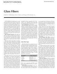
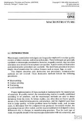
<strong>Extrusion</strong> is a plastic deformation process in which a block <strong>of</strong> metal<br />
(billet) is forced to flow by compression through the die opening <strong>of</strong> a<br />
smaller cross-sectional area than that <strong>of</strong> the original billet as shown in<br />
Fig. 1. <strong>Extrusion</strong> is an indirect-compression process. Indirect-compressive<br />
Definition <strong>of</strong> <strong>Extrusion</strong>
2 / Aluminum <strong>Extrusion</strong> Technology<br />
Fig. 1 Definition and principle <strong>of</strong> extrusion<br />
forces are developed by the reaction <strong>of</strong> the workpiece (billet) with the<br />
container and die; these forces reach high values. The reaction <strong>of</strong> the<br />
billet with the container and die results in high compressive stresses that<br />
are effective in reducing the cracking <strong>of</strong> the billet material during primary<br />
breakdown from the billet (Ref 2). <strong>Extrusion</strong> is the best method<br />
for breaking down the cast structure <strong>of</strong> the billet because the billet is<br />
subjected to compressive forces only.<br />
<strong>Extrusion</strong> can be cold or hot, depending on the alloy and the method<br />
used. In hot extrusion, the billet is preheated to facilitate plastic deformation.<br />
Classification <strong>of</strong> <strong>Extrusion</strong> Processes<br />
The two basic types <strong>of</strong> extrusion are direct and indirect, which are<br />
commonly used in aluminum industries as shown in Fig. 1 and 6. Solid<br />
and hollow shapes are designed and extruded for a wide range <strong>of</strong> programs:<br />
• Solid sections, bars, and rods extruded from solid billets by direct<br />
extrusion (discussed in Chapter 3)<br />
• Tubes and hollow sections extruded from solid billets through porthole<br />
or bridge-type dies (for certain alloys) by direct extrusion (discussed<br />
in Chapter 6)<br />
• Tubes and hollow sections extruded from hollow or solid billets<br />
(latter pierced in the press via floating mandrel) by direct extrusion<br />
(discussed in Chapter 3)<br />
• Tubes and hollow sections extruded from hollow or solid billets<br />
(latter pierced in the press via stationary mandrel) by direct extrusion<br />
• Critical solid sections, bars, and rods extruded from solid billets<br />
with sealed container through the die mounted on the stem by indirect<br />
extrusion (discussed in Chapter 3)
• Tubes and hollow sections extruded from hollow or solid billets<br />
(latter pierced in press) via stationary mandrel through the die<br />
mounted on the stem by the indirect extrusion process<br />
Conventional Direct <strong>Extrusion</strong><br />
The most important and common method used in aluminum extrusion<br />
is the direct process. Figure 1 shows the principle <strong>of</strong> direct extrusion<br />
where the billet is placed in the container and pushed through the die by<br />
the ram pressure. Direct extrusion finds application in the manufacture<br />
<strong>of</strong> solid rods, bars, hollow tubes, and hollow and solid sections according<br />
to the design and shape <strong>of</strong> the die. In direct extrusion, the direction<br />
<strong>of</strong> metal flow will be in the same direction as ram travel. During this<br />
process, the billet slides relative to the walls <strong>of</strong> the container. The resulting<br />
frictional force increases the ram pressure considerably. During<br />
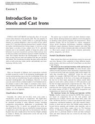
direct extrusion, the load or pressure-displacement curve most commonly<br />
has the form shown in Fig. 2. Traditionally, the process has been<br />
described as having three distinct regions:<br />
1. The billet is upset, and pressure rises rapidly to its peak value.<br />
2. The pressure decreases, and what is termed “steady state” extrusion<br />
proceeds.<br />
3. The pressure reaches its minimum value followed by a sharp rise as<br />
the “discard” is compacted.<br />
Billet-on-Billet <strong>Extrusion</strong><br />
Billet-on-billet extrusion is a special method for aluminum alloys that<br />
are easily welded together at the extrusion temperature and pressure.<br />
Using this process, continuous lengths <strong>of</strong> a given geometry (shape) can<br />
be produced by different methods. Billet-on-billet extrusion is also a viable<br />
process in the production <strong>of</strong> coiled semifinished products for further<br />
Fig. 2 Variation <strong>of</strong> load or pressure with ram travel for both direct and indirect<br />
extrusion process<br />
<strong>Fundamentals</strong> <strong>of</strong> <strong>Extrusion</strong> / 3
4 / Aluminum <strong>Extrusion</strong> Technology<br />
processing, such as rod and tube drawing production. Perfect welding<br />
<strong>of</strong> the billet in the container with the following billet must take place as<br />
the joint passes through the deformation zone. The following requirements<br />
have to be fulfilled (Ref 3):<br />
• Good weldability at the temperature <strong>of</strong> deformation<br />
• Accurate temperature control<br />
• Cleaned billet surface<br />
• Sawn, clean billet ends free from grease<br />
• Bleeding <strong>of</strong> air from the container at the start <strong>of</strong> the extrusion using<br />
taper-heated billet as shown in Fig. 3 to avoid blisters and other defects<br />
Two methods <strong>of</strong> billet-on-billet extrusion have been developed. In the<br />
first method, the discard is removed, and the following billet is welded<br />
to the one remaining in the welding or feeder plate (Fig. 4).<br />
Fig. 3 Bleeding out air during upsetting<br />
Fig. 4 Continuous-type extrusion using welding plate in front <strong>of</strong> the die<br />
(method 1)
The second method does not need a discard; the subsequent billet is<br />
pressed directly onto the billet still in the container as shown in Fig. 5.<br />
The dummy block attached with the stem shears an aluminum ring from<br />
the container during each return stroke, and this has to be removed from<br />
the stem (Ref 3).<br />
Indirect <strong>Extrusion</strong><br />
In indirect extrusion, the die at the front end <strong>of</strong> the hollow stem moves<br />
relative to the container, but there is no relative displacement between<br />
the billet and the container as shown in Fig. 6. Therefore, this process is<br />
characterized by the absence <strong>of</strong> friction between the billet surface and<br />
the container, and there is no displacement <strong>of</strong> the billet center relative to<br />
the peripheral regions. The variation <strong>of</strong> load or pressure with the ram<br />
travel during both direct and indirect extrusion processes is shown in<br />
Fig. 2.<br />
Fig. 5 Billet-on-billet extrusion (method 2)<br />
Fig. 6 Indirect extrusion process<br />
<strong>Fundamentals</strong> <strong>of</strong> <strong>Extrusion</strong> / 5
6 / Aluminum <strong>Extrusion</strong> Technology<br />
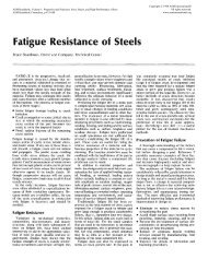
Mechanics <strong>of</strong> <strong>Extrusion</strong><br />
Plastic Deformation and Metal Flow<br />
In metal forming, plasticity theory is applied to investigate the mechanics<br />
<strong>of</strong> plastic deformation. The investigation allows the analysis<br />
and prediction <strong>of</strong> the following:<br />
• Metal flow, including velocities, strain rates, and strain<br />
• Temperature and heat transfer<br />
• Variation <strong>of</strong> local material strength or flow stress <strong>of</strong> material<br />
• Stresses, forming load, pressure, and energy<br />
The mechanics <strong>of</strong> plastic deformation provide the means for determining<br />
how the metal flows in different forming operations, the means<br />
<strong>of</strong> obtaining desired geometry through plastic deformation, and the<br />
means for determining the expected mechanical and physical properties<br />
<strong>of</strong> the metal produced. Different mathematical equations can be obtained<br />
through a different approach (Ref 4 to 7) for different forming<br />
operations, including extrusion.<br />
In simple homogeneous (uniaxial) compression or in tension, the<br />
metal flows plastically when the stress, σ, reaches the value <strong>of</strong> flow<br />
stress, σ. The flow <strong>of</strong> aluminum during extrusion is intermetallic shear<br />
flow. The significant difference in the shear flow <strong>of</strong> aluminum compared<br />
with other metals being extruded is that the center <strong>of</strong> the aluminum<br />
billet is extruded first, and the peripheral part <strong>of</strong> the billet flows<br />
later, causing more severe shear deformation. As soon as the force required<br />
to push the billet into the container surface exceeds that <strong>of</strong> the<br />
shear strength <strong>of</strong> the billet material, sticking friction predominates, and<br />
deformation proceeds by shear in the bulk <strong>of</strong> the billet. Metal flow during<br />
extrusion depends on many factors, such as the following:<br />
• Billet material property at billet temperature<br />
• Billet-container interface and metal-die interface friction<br />
• <strong>Extrusion</strong> ratio<br />
A fairly large number <strong>of</strong> investigations <strong>of</strong> the flow characteristics <strong>of</strong><br />
metal, such as lead, tin, and aluminum, have been made by using a<br />
split-billet technique (Ref 3 and 7 to 9). Typical flow patterns observed<br />
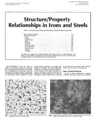
in extrusion are shown in Fig. 7 (Ref 3).<br />
In extrusion <strong>of</strong> homogeneous materials, flow pattern S is found in the<br />
absence <strong>of</strong> friction at the container and die interfaces. The extrusion<br />
properties should be uniform in both longitudinal and transverse directions,<br />
respectively. This flow pattern is usually obtained in fully lubricated<br />
conditions in both container and dies.
Fig. 7 Schematic <strong>of</strong> the four different types <strong>of</strong> flow in extrusion. Source: Ref 3<br />
Flow pattern A is obtained in extrusion <strong>of</strong> homogeneous materials in<br />
the presence <strong>of</strong> friction at the die interface, not at the container-billet interface.<br />
This flow pattern is good for indirect extrusion. The metal at the<br />
center <strong>of</strong> the billet moves faster than the metal at the periphery. In the<br />
corner <strong>of</strong> the leading end <strong>of</strong> the billet, a separate metal zone is formed<br />
between the die face and the container wall, known as a dead-metal<br />
zone. The material near the surface undergoes shear deformation compared<br />
with the pure deformation at the center, and it flows diagonally<br />
into the die opening to form the outer shell <strong>of</strong> extrusion.<br />
Flow pattern B is obtained in homogeneous materials when there is<br />
friction in both container and die interfaces. This flow pattern is good<br />
for direct extrusion processes. An extended dead-metal zone is formed.<br />
In this case, there is more shear deformation compared with that in flow<br />
pattern A. The extrusion has nonuniform properties compared with that<br />
in flow pattern A.<br />
Flow pattern C is obtained with billets having inhomogeneous material<br />
properties or with a nonuniform temperature distribution in the billet.<br />
Materials undergo more severe shear deformation at the container<br />
wall and also form a more extended dead-metal zone.<br />
The properties <strong>of</strong> the extruded aluminum shapes are affected greatly<br />
by the way in which the metal flows during extrusion. The metal flow is<br />
influenced by many factors:<br />
Type <strong>of</strong> extrusion, direct or indirect<br />
Press capacity and size and shape <strong>of</strong> container<br />
Frictional effects at the die or both container and die<br />
Type, layout, and design <strong>of</strong> die<br />
The length <strong>of</strong> billet and type <strong>of</strong> alloy<br />
The temperature <strong>of</strong> the billet and container<br />
The extrusion ratio<br />
Die and tooling temperature<br />
Speed <strong>of</strong> extrusion<br />
Type, layout, and design <strong>of</strong> the die might change the mechanical<br />
working <strong>of</strong> the billet material during extrusion. Hollow dies perform<br />
<strong>Fundamentals</strong> <strong>of</strong> <strong>Extrusion</strong> / 7
8 / Aluminum <strong>Extrusion</strong> Technology<br />
much more mechanical work on the material than simple-shape solid<br />
dies do.<br />
A dead-metal zone builds up in the corners <strong>of</strong> the die, and the material<br />
shears along this face. The material may continue to extrude over this<br />
generated zone, which acts like a conical die surface. The surface and<br />
subsurface defects are likely to occur on the extruded product if the sufficient<br />
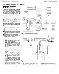
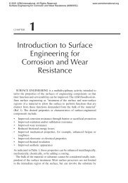
amount <strong>of</strong> butt is not kept. Typical etched cross section <strong>of</strong> a 7075<br />
alloy butt remaining after extrusion is shown in Fig. 8(a). Figure 8(b)<br />
shows schematically two clear zones. Zone 1 shows the flowing metal<br />
through the rigid conical zone 2, which is defined to be a dead-metal<br />
zone. The darker patches carry oxides and other inclusions into the extruded<br />
section, leading to extrusion defects.<br />
The dead-metal zone semiangle may be represented in the functional<br />
form:<br />
α = f(ER, σ, m, m′) (Eq 1)<br />
where ER is the extrusion ratio, which is defined by the ratio <strong>of</strong> container<br />
bore area and the total cross-sectional area <strong>of</strong> extrusion, σ is the<br />
flow stress, m is the friction factor between billet and container interface,<br />
and m′ is the friction factor between flowing metal and die-bearing<br />
interface.<br />
Under the same friction condition at the billet-container interface for<br />
the same alloy billet, the dead-metal zone semiangle (α) varies with the<br />
extrusion ratio, ER, as shown in Fig. 9. As the extrusion ratio increases,<br />
α increases, and as α increases, the length <strong>of</strong> shear line decreases. In<br />
Fig. 9, ER 1 is the extrusion ratio for the bigger opening die, whereas<br />
ER 2 is the extrusion ratio <strong>of</strong> the smaller opening die, and α 2 is the<br />
semidead-metal zone angle corresponding to ER 2 .<br />
Butt Thickness. According to industry practice, standard butt thickness<br />
for direct extrusion is kept to 10 to 15% <strong>of</strong> the billet length. Butt<br />
thickness may be a function <strong>of</strong> the dead-metal zone, which is also a<br />
function <strong>of</strong> the extrusion ratio, type <strong>of</strong> die, billet temperature, billetcontainer<br />
friction condition, and flow stress <strong>of</strong> the billet material. Figure<br />
10 shows the relationship between butt thickness and the deadmetal<br />
zone conical surface. Stopping extrusion at the safe margin zone<br />
prevents oxide and other metallic or nonmetallic inclusions from flowing<br />
into the extrusion. It is always recommended to continue research<br />
on macroetching <strong>of</strong> the longitudinal section <strong>of</strong> the butt to gain a better<br />
understanding <strong>of</strong> the following aspects:<br />
• Change <strong>of</strong> the dead-metal zone conical angle with the change <strong>of</strong> extrusion<br />
variables<br />
• Change <strong>of</strong> the dead-metal zone with the change <strong>of</strong> die opening<br />
(number <strong>of</strong> holes) and types <strong>of</strong> dies (solid and hollow)
X X<br />
(b)<br />
(a)<br />
α<br />
Shear line<br />
Fig. 8 Longitudinal cross section <strong>of</strong> butt after extrusion. (a) Typical etched<br />
cross section <strong>of</strong> a 7075 butt. (b) Schematic diagram <strong>of</strong> butt cross section<br />
showing dead zone<br />
1<br />
2
10 / Aluminum <strong>Extrusion</strong> Technology<br />
Fig. 9 Relationship between extrusion ratio and semidead-metal zone angle<br />
Fig. 10 Relationship between dead zone and butt thickness<br />
• Determination <strong>of</strong> the optimum butt thickness for a set <strong>of</strong> extrusion<br />
and die variables<br />
• Metal flow and formation <strong>of</strong> the dead-metal zone in case <strong>of</strong> indirect<br />
extrusion<br />
This is more important for harder alloy extrusion, especially in the aircraft<br />
industry. The press should be stopped within the safe margin zone<br />
as shown in Fig. 10.<br />
Plastic Strain and Strain Rate<br />
In order to investigate metal flow quantitatively, it is necessary to define<br />
the strain (deformation) and strain rate (deformation rate). In the<br />
theory <strong>of</strong> metal forming plasticity, the initial condition cannot be used
as a frame <strong>of</strong> reference; therefore, the change in length must be related<br />
to instantaneous length. The natural or effective strain is defined by:<br />
dε<br />
=<br />
dl<br />
ε =<br />
dl<br />
= ln<br />
l<br />
l ∫<br />
(Eq 2)<br />
l l0<br />
where, l 0 is the initial length, and l is the final length.<br />
The natural strain, ε, obtained by integration is thus a logarithmic<br />
function and is <strong>of</strong>ten referred to as the logarithmic strain. The strain in<br />
metal working is given as the fractional cross-sectional area. The volume<br />
constancy relation is given by:<br />
Al = A 0 l 0<br />
Now, the natural strain is given by:<br />
–<br />
ε = ln<br />
l<br />
= ln<br />
A<br />
A<br />
l 0<br />
0<br />
(Eq 3)<br />
where A 0 is the original area, and A is the final area.<br />
Therefore, the effective strain is defined in the case <strong>of</strong> extrusion as:<br />
–<br />
ε = 2 ln<br />
D<br />
D<br />
C =<br />
E<br />
2 ln<br />
ER<br />
where D C is the inside diameter <strong>of</strong> the container and D E is the equivalent<br />
diameter <strong>of</strong> the extruded rod, and ER is the extrusion ratio.<br />
In determining the strain rate, the complex flow pattern in the deformation<br />
zone creates a problem. The material undergoes a rapid acceleration<br />
as its passes through the deformation zone, and therefore, a mean<br />
strain rate has to be estimated for determining the flow stress. The deformation<br />
zone is assumed to be conical for simplicity as shown in Fig. 11.<br />
From the geometry, the length <strong>of</strong> deformation zone is given by:<br />
L =<br />
DC<br />
− D )<br />
2 tan α<br />
( E<br />
l<br />
l0<br />
where D C is the bore <strong>of</strong> the container, D E is the diameter <strong>of</strong> the extruded<br />
rod, and α is the dead-metal zone semiangle.<br />
Equivalent rod diameter for the same extrusion ratio can also be determined.<br />
The extrusion ratio <strong>of</strong> a single-hole die is defined by:<br />
ER =<br />
A<br />
A<br />
C<br />
E<br />
<strong>Fundamentals</strong> <strong>of</strong> <strong>Extrusion</strong> / 11<br />
(Eq 4)<br />
(Eq 5)<br />
(Eq 6)<br />
(Eq 7)
12 / Aluminum <strong>Extrusion</strong> Technology<br />
Fig. 11 Billet geometry inside the container<br />
where A C is the area <strong>of</strong> the container bore, and A E is the final area <strong>of</strong> the<br />
extruded rod. Therefore, the equivalent diameter <strong>of</strong> the extruded rod is<br />
given by:<br />
D E =<br />
DC<br />
ER<br />
The mean effective strain rate is given by (Ref 10 and 11):<br />
⋅<br />
ε =<br />
6V<br />
D tan α<br />
2<br />
3 3<br />
( D − DE)<br />
C<br />
2<br />
C ln<br />
where V is the average ram speed, D C is the container bore, D E is the diameter<br />
<strong>of</strong> the extruded rod, and α is the dead-metal zone semiangle.<br />
Friction Models<br />
D<br />
D<br />
C<br />
E<br />
(Eq 8)<br />
(Eq 9)<br />
<strong>Fundamentals</strong> <strong>of</strong> tribology (friction, lubrication, and wear) are essential<br />
in dealing with the field <strong>of</strong> metal-working processes. During the extrusion<br />
<strong>of</strong> aluminum, the tribology <strong>of</strong> the die/material interface has a<br />
considerable influence on the accuracy <strong>of</strong> the shape and surface quality<br />
<strong>of</strong> the extrusion. In this section, friction modeling <strong>of</strong> the extrusion process<br />
is discussed.<br />
Friction components are totally dependent on the type <strong>of</strong> extrusions<br />
used, such as direct or indirect. Figure 12 shows the friction-force components<br />
in direct extrusion, and similarly, Fig. 13 shows the friction<br />
components in the indirect process using the most common flat-face dies.<br />
From the flow pattern in indirect extrusion using a flat-face die, it is<br />
revealed that a dead-metal zone exists with a much higher angle compared<br />
with that in direct extrusion. For the same size extrusion, α i > α d .<br />
Thin butt may be allowed in indirect process. The metal flow in the indirect
process using a flat-face die may be very similar to the flow with lubricated<br />
direct extrusion process.<br />
Friction is the resistance to relative motion that is experienced whenever<br />
two solids are in contact with each other. The force necessary to<br />
overcome the resistance, which is directed in the direction opposite to<br />
the relative motion, is the friction force. The Amontons-Coulomb<br />
model (Ref 12) gives the friction force as:<br />
F f = µN (Eq 10)<br />
where µ is the coefficient <strong>of</strong> friction, N is the normal force, and F f is the<br />
friction force. The model holds fairly well where contacts are relatively<br />
lightly loaded, and the surfaces contact only at occasional asperity<br />
peaks. This model is <strong>of</strong> questionable value in bulk deformation processes,<br />
such as extrusion, where the contact is more intimate and the<br />
pressures are significantly higher.<br />
Billet-Container Interface. The real area <strong>of</strong> contact increases with<br />
contact pressure as shown in Fig. 14. According to Bowden and Tabor<br />
Fig. 12 Friction components in direct extrusion<br />
Fig. 13 Friction components in indirect extrusion<br />
<strong>Fundamentals</strong> <strong>of</strong> <strong>Extrusion</strong> / 13
14 / Aluminum <strong>Extrusion</strong> Technology<br />
(Ref 13), the friction force using adhesion theory is directly proportional<br />
to the real area <strong>of</strong> contact. In the case <strong>of</strong> direct extrusion (where<br />
contact pressures are very high), the real area <strong>of</strong> contact, A R , gradually<br />
becomes equal to the apparent area <strong>of</strong> contact, A A , as the billet upsets in<br />
the container.<br />
Important considerations in the direct extrusion process are the friction<br />
forces developed between the billet and the container and interface<br />
friction between the flowing metal and the dead-metal zone conical interface.<br />
In the direct extrusion process, the large pressure developed demands<br />
that the billet be supported by the container wall. From a practical<br />
point <strong>of</strong> view, there are two types <strong>of</strong> friction conditions:<br />
• Billet-container friction is arrested (sticking friction)<br />
• Lubricated interface flow is ensured (sliding friction)<br />
In aluminum extrusion, the friction condition at the billet-container<br />
interface is considered to be sticking friction as the skin <strong>of</strong> the billet is<br />
being separated in the container wall. Schey (Ref 14) provides a useful<br />
review <strong>of</strong> using the friction factor, m, in metal-forming operations<br />
where the contact pressure is very high. The friction factor model,<br />
sometimes referred to as a stiction model, is:<br />
F f = mkA R<br />
(Eq 11)<br />
where m is the friction factor, k is the material shear strength, AR is the<br />
real area <strong>of</strong> contact (which, for this model, equals the total area <strong>of</strong> contact),<br />
and Ff is the friction force. In the case <strong>of</strong> sticking friction, m = 1, while<br />
for thick film lubrication conditions, m approaches zero. Therefore, the<br />
frictional stress, τf , is given by:<br />
σ<br />
–<br />
τ f = k =<br />
(Eq 12)<br />
3<br />
where k is equal to σ/ 3 according to Von Mises yield criteria, and σ is<br />
the flow stress <strong>of</strong> the material.<br />
Fig. 14 Friction model in direct extrusion process. (a) A R < A A . (b) A R =A A ,p=σ
Dead-Metal Zone-Flowing Metal Interface. The dead-metal zone<br />
shown in Fig. 12 occurs when a material is extruded through square dies<br />
(i.e., the bearing surface is perpendicular to the face <strong>of</strong> the die). In such<br />
geometry, the material in the corners no longer takes part in the flow but<br />
adheres to the die face, forming a conical die-like channel through<br />
which the billet passes in a still-converging kind <strong>of</strong> flow. Friction between<br />
the dead-metal zone and the flowing material is no more than the<br />
shear stress <strong>of</strong> the material. The friction stress is also given by Eq 12<br />
with friction factor equal to unity.<br />
Die-Material Interface. Based on the observation <strong>of</strong> the die surface<br />
after several extrusion cycles, it is understood that friction in the die can<br />
vary in a complicated way when metal is flowing through the die opening.<br />
It has been observed that an adhesive layer on the die develops due<br />
to the strong adhesion <strong>of</strong> materials such as aluminum with the dies, typically<br />
constructed from tool steels. It is also understood that surface<br />
treatments (such as nitriding or thin hard coatings) that result in harder<br />
die bearing can reduce the amount <strong>of</strong> adhered aluminum on the die bearing.<br />
Research is continuing on die bearing treatments for wear resistance.<br />
A friction model developed by Abtahi (Ref 15) is based on measured<br />
slipping and sticking lengths using a split die. This model shows almost<br />
constant friction in the sticking region, whereas in the slipping region,<br />
friction is changing with the die angle.<br />
Proposed Model. In a recent study, Saha (Ref 16) suggested a friction<br />
model at the die-material interface. Figure 15 is a schematic <strong>of</strong> the<br />
bearing surface based on the morphology <strong>of</strong> aluminum buildup on the<br />
die bearing, which is normal to the extrusion direction. Figure 15 also<br />
shows the sticking and slipping zones <strong>of</strong> the die that are used to develop<br />
a friction model at the die-material interface. Figure 15(a) shows partial<br />
sticking and slipping zones, and Fig. 15(b) shows a completely adhered<br />
surface. After several press cycles, a completely adhered surface is developed<br />
on the die face.<br />
During extrusion, the normal pressure on the bearing surface <strong>of</strong> the<br />
die is very high. This pressure is assumed to be equal to the extrusion<br />
pressure, which is equal to or higher than the flow stress <strong>of</strong> the material.<br />
Based on the definition <strong>of</strong> the friction factor, the friction force F f on the<br />
die is given by:<br />
= m k A<br />
+ m k A<br />
F 1 2 R<br />
f<br />
1<br />
R 2<br />
where a 1 subscript denotes a sticking zone, a 2 subscript denotes a sliding<br />
zone, m is the friction factor, A R is the real area <strong>of</strong> contact, and k is<br />
the material shear strength. The friction stress is given by:<br />
τ<br />
f<br />
A<br />
= k<br />
A<br />
R<br />
A<br />
1 +<br />
AR2<br />
m2k<br />
AA<br />
<strong>Fundamentals</strong> <strong>of</strong> <strong>Extrusion</strong> / 15<br />
(Eq 13)<br />
(Eq 14)
16 / Aluminum <strong>Extrusion</strong> Technology<br />
Fig. 15 Schematic <strong>of</strong> the morphology <strong>of</strong> the die bearing surface<br />
where A A is the apparent area <strong>of</strong> contact for the entire bearing surface,<br />
and m 1 has been set equal to unity to reflect sticking friction.<br />
In the case <strong>of</strong> complete adhesion (sticking friction) on the die bearing,<br />
m 2 = 1; accordingly, the frictional stress will be changed to:<br />
AR1<br />
+ AR2<br />
τ f = k = k =<br />
AA<br />
<strong>Extrusion</strong> Pressure<br />
σ–<br />
3<br />
The parameter that determines whether extrusion will proceed or<br />
whether a sticker will result is the magnitude <strong>of</strong> the maximum pressure<br />
that must be within the extrusion press capacity. The factors that influence<br />
successful extrusion are as follows:<br />
• <strong>Extrusion</strong> temperature<br />
• Temperature <strong>of</strong> container, die, and associated tooling<br />
• <strong>Extrusion</strong> pressure<br />
• <strong>Extrusion</strong> ratio<br />
• <strong>Extrusion</strong> speed<br />
• Billet length<br />
• Chemistry <strong>of</strong> the alloy<br />
(Eq 15)<br />
In the direct extrusion process, pressure reaches a maximum at the<br />
point <strong>of</strong> breakout at the die. A typical pressure curve is shown in Fig. 2.<br />
The difference between the maximum and minimum pressures can be<br />
attributed to the force required in moving the billet through the container<br />
against the frictional force. The actual pressure exerted on the
am is the total pressure. The total extrusion pressure required for a particular<br />
extrusion ratio is given by:<br />
P T = P D + P F + P R<br />
<strong>Fundamentals</strong> <strong>of</strong> <strong>Extrusion</strong> / 17<br />
(Eq 16)<br />
where P D is the pressure required for the plastic deformation <strong>of</strong> the material,<br />
which is given in the functional form as:<br />
P D =f (σ, ε) (Eq 17)<br />
where the flow stress, σ, is defined by:<br />
– ⋅<br />
σ = f ( ε,<br />
ε,<br />
T)<br />
(Eq 18)<br />
strain and strain rate are defined by:<br />
–<br />
ε = ln<br />
A<br />
A<br />
C<br />
E<br />
(Eq 19)<br />
– ⋅<br />
ε<br />
d<br />
–<br />
=<br />
ε<br />
(Eq 20)<br />
dt<br />
and T is the temperature <strong>of</strong> the material.<br />
P F is the pressure required to overcome the surface friction at the container<br />
wall friction, dead-metal zone friction, and die bearing friction,<br />
which is given in the functional form<br />
P F = f (p r , m, m′, m″, D, L, L′) (Eq 21)<br />
where p r is the radial pressure, m is the friction factor between the billet<br />
and container wall, m′ is the friction factor at the dead-metal zone/flowing<br />
metal interface, m″ is the friction factor between extruded material and<br />
die bearing, D is the billet diameter, L is the length <strong>of</strong> the billet, and L′ is<br />
the die bearing length <strong>of</strong> a solid die.<br />
P R is the pressure to overcome redundant or internal deformation<br />
work, which is given in the functional form<br />
P R = f (σ, α) (Eq 22)<br />
where α is the semidead-metal zone angle as a function <strong>of</strong> the extrusion<br />
ratio.<br />
Dieter (Ref 2) has given a nice explanation <strong>of</strong> the redundant work. Elements<br />
at the center <strong>of</strong> the billet undergo essentially pure elongation in<br />
the extruded rod, which corresponds to the change in cross section from<br />
billet to extrusion. The elements shown in Fig. 16, near the container<br />
wall, undergo extensive shear deformation due to billet-container interface
18 / Aluminum <strong>Extrusion</strong> Technology<br />
friction. The elements at the dead-metal zone interface also undergo extensive<br />
shear deformation. The shear deformation, which occurs over<br />
much <strong>of</strong> the cross section <strong>of</strong> the extruded rod, requires an expenditure <strong>of</strong><br />
energy. This energy expenditure, which is not related to the change in<br />
dimensions from the billet to the extrusion, is called redundant work, as<br />
shown in Fig. 16. The redundant work is mainly responsible for the<br />
large difference between the actual extrusion pressure and the calculated<br />
pressure on the basis <strong>of</strong> uniform plastic deformation.<br />
For a given size <strong>of</strong> billet extruded under a particular set <strong>of</strong> conditions,<br />
there will be an upper limit to the extrusion ratio that can be obtained<br />
with a press <strong>of</strong> a given capacity. The temperature <strong>of</strong> extrusion plays the<br />
most important role in getting a properly extruded product, and extrusion<br />
speed are also important factors. An increase in the length <strong>of</strong> the<br />
billet, however, results in raising the pressure required for extrusion.<br />
This increase in pressure is due to the frictional resistance between the<br />
billet and the container wall, which is greater for the longer billet.<br />
Normally, the maximum length <strong>of</strong> the billet is four times its diameter.<br />
In extrusion <strong>of</strong> metals, there are certain interrelations between extrusion<br />
pressures, extrusion temperatures, extrusion ratios, and extrusion<br />
speeds:<br />
• Increase in the temperature <strong>of</strong> the billet reduces the pressure required<br />
for extrusion.<br />
• The higher the extrusion ratio, the higher the extrusion pressure.<br />
• The greater the billet length, the higher the extrusion pressure.<br />
Fig. 16 Redundant work
• Billet temperature remains within extrusion range; extrusion pressure<br />
remains fairly unaffected when extrusion speed is increased<br />
within normal limits.<br />
Analysis <strong>of</strong> <strong>Extrusion</strong> Pressure<br />
Slab Method. In this section, the average extrusion pressure during<br />
direct extrusion <strong>of</strong> aluminum is calculated by using the slab method.<br />
Thomsen et al. (Ref 7) have shown an analysis by using a uniform energy<br />
method, slab analysis, and slip-line field theory. Altan et al. (Ref<br />
17) have performed a slab method analysis to determine the extrusion<br />
pressure. The following considerations were used in making the analysis:<br />
• <strong>Extrusion</strong> using a cylindrical billet through a flat die<br />
• <strong>Extrusion</strong> shape equivalent to a rod <strong>of</strong> diameter D E<br />
• Frictional shear stress at the dead-metal/flowing metal interface<br />
• Frictional shear stress at the billet-container interface<br />
Consider the static equilibrium <strong>of</strong> the forces acting on the shaded element<br />
within the dead-metal zone area as shown in Fig. 17. The stresses<br />
acting on this slab are shown in Fig. 18(b). The equilibrium equation is<br />
given by:<br />
π ( D + dD)<br />
− ( p z + dp )<br />
z 4<br />
+<br />
πD<br />
pz<br />
4<br />
+ pr<br />
π D dssinα<br />
(Eq 23)<br />
+ τ πD<br />
dscosα<br />
= 0<br />
f<br />
where τ f is the frictional stress at the dead-metal zone/flowing material<br />
interface, p r is the radial pressure and α is the semidead-metal zone angle.<br />
This equation can be simplified by using the following geometric relationship<br />
among dz, dD, and ds:<br />
dD<br />
ds sinα<br />
= dz tanα<br />
=<br />
2<br />
dD<br />
ds cosα<br />
= dz =<br />
2tanα<br />
From the yield criterion,<br />
2<br />
2<br />
p r = p z + σ (Eq 26)<br />
where p r is the radial pressure, p z is the pressure in the Z direction and σ<br />
is the flow stress <strong>of</strong> the material.<br />
<strong>Fundamentals</strong> <strong>of</strong> <strong>Extrusion</strong> / 19<br />
(Eq 24)<br />
(Eq 25)
20 / Aluminum <strong>Extrusion</strong> Technology<br />
Combining Eq 23, 24, 25, and 26, substituting τ f from Eq 12, and neglecting<br />
the higher order differentials, the equilibrium equation is obtained<br />
in the integral form:<br />
dpz 2dD<br />
– cot<br />
=<br />
σ ( 1+<br />
α<br />
) D<br />
3<br />
Assuming the flow stress remains constant, the integration <strong>of</strong> the equation<br />
yields:<br />
pz 2<br />
= ln<br />
– cotα<br />
σ ( 1+<br />
)<br />
3<br />
D C<br />
where C is the integration constant.<br />
Fig. 17 <strong>Extrusion</strong> through a square die with dead-metal zone and equivalent<br />
rod diameter<br />
Fig. 18 State <strong>of</strong> stress for the extrusion shown in Fig. 17. (a) Freebody diagram<br />
<strong>of</strong> element inside the container wall. (b) Freebody diagram <strong>of</strong><br />
element under the dead-metal zone. (c) Geometric relationship among dz, dD,<br />
and ds<br />
(Eq 27)<br />
(Eq 28)
Substituting the boundary conditions at D = D E , p z =0,C will be determined<br />
by:<br />
where D E , the equivalent diameter <strong>of</strong> extruded rod, could be calculated<br />
by using Eq 8.<br />
Substituting the value <strong>of</strong> constant, C, in Eq 28 and simplifying, the average<br />
extrusion pressure is given by:<br />
p<br />
ave, z=<br />
0<br />
– cotα<br />
= 2σ<br />
( 1+<br />
) ln<br />
D<br />
3 D<br />
where D C is the equivalent diameter <strong>of</strong> the billet (container bore diameter)<br />
filled in the container after upsetting.<br />
Billet-Container Interface Friction. Billet-container interface friction<br />
must be included to determine the total pressure required for extrusion<br />
from a round-shaped billet to an equivalent rod. Considering the<br />
shaded element in the cylindrical portion (Fig. 17), the equation expressing<br />
static equilibrium in the Z direction is given by:<br />
2<br />
z z z 4 =<br />
[ ( p dp ) p ] πDC<br />
π D τ dz<br />
− +<br />
C<br />
C<br />
E<br />
f<br />
where, τ f is the friction force at the billet-container interface, D C is the<br />
diameter <strong>of</strong> the container bore. Equation 31 may be written in the integral<br />
form:<br />
dpz<br />
4<br />
τ<br />
=<br />
D<br />
f<br />
C<br />
dz<br />
Integrating Eq 32 and putting the boundary condition: at Z =0,p z =<br />
p ave, z=0 , the average extrusion pressure may be written as:<br />
Now substituting p ave, z=0 from Eq 30 and τ f from Eq 12, the average<br />
extrusion pressure may be written as:<br />
p<br />
1<br />
=<br />
D<br />
C 2 E<br />
ave<br />
DC<br />
= 2σ<br />
–<br />
( 1+<br />
cot α<br />
) ln +<br />
3 DE<br />
4σ<br />
–<br />
Z<br />
3 D<br />
C<br />
<strong>Fundamentals</strong> <strong>of</strong> <strong>Extrusion</strong> / 21<br />
(Eq 29)<br />
(Eq 30)<br />
(Eq 31)<br />
(Eq 32)<br />
4 f Z<br />
= + p<br />
D ave, =<br />
τ (Eq 33)<br />
pz z 0<br />
C<br />
(Eq 34)
22 / Aluminum <strong>Extrusion</strong> Technology<br />
Avitzur (Ref 18) used an upper-bound method to derive an equation to<br />
predict extrusion load.<br />
<strong>Extrusion</strong> Force<br />
The force required for extrusion depends on the flow stress <strong>of</strong> the billet<br />
material, the extrusion ratio, the friction condition at the billet container<br />
interface, the friction condition at the die material interface, and<br />
the other process variables, such as initial billet temperature and the<br />
speed <strong>of</strong> extrusion. The required extrusion force, F r , is given by:<br />
F r = P T A C<br />
(Eq 35)<br />
where P T is the extrusion pressure, and A C is the area <strong>of</strong> the container<br />
bore.<br />
The force term is essential in determining the capacity <strong>of</strong> the extrusion<br />
press. The external force given by the extrusion press will determine<br />
the press capacity. For successful extrusion, the force balance has<br />
to be satisfied as follows:<br />
F p > F r<br />
where F p is the force applied by the press, and F r is the force required for<br />
extrusion. Force (compression power) applied by the press is given by:<br />
F p = pA 1 + p(2A 2 ) (Eq 36)<br />
where A 1 is the area <strong>of</strong> the main cylinder, A 2 is the area <strong>of</strong> each side cylinder,<br />
and p is the applied hydraulic pressure to the cylinders as shown<br />
in Fig. 19.<br />
Specific pressure (inner pressure in the container liner) as shown in<br />
Fig. 20 is given by:<br />
P<br />
s =<br />
F<br />
A<br />
p<br />
C<br />
Effect <strong>of</strong> Principal Variables on <strong>Extrusion</strong><br />
(Eq 37)<br />
<strong>Extrusion</strong> can become impossible or can yield an unsatisfactory product<br />
when the load required exceeds the capacity <strong>of</strong> the press available or<br />
when the temperature <strong>of</strong> the extrusion exceeds the solidus temperature<br />
<strong>of</strong> the alloy. Knowledge <strong>of</strong> the initial billet temperature, the strain-rate,<br />
flow stress <strong>of</strong> the working material, and the extrusion ratio are required<br />
if correct and economical use is to be made <strong>of</strong> expensive extrusion facilities.
Fig. 19 Schematic <strong>of</strong> direct extrusion press<br />
Fig. 20 Specific applied pressure<br />
Principal Variables<br />
The principal variables (Fig. 21) that influence the force required to<br />
cause extrusion and the quality <strong>of</strong> material exiting from the die are as<br />
follows:<br />
• <strong>Extrusion</strong> ratio<br />
• Working temperature<br />
• Speed <strong>of</strong> deformation<br />
• Alloy flow stress<br />
<strong>Extrusion</strong> Ratio. The extrusion ratio (ER) <strong>of</strong> a multihole die is defined<br />
by:<br />
C<br />
ER =<br />
A<br />
n(<br />
AE)<br />
<strong>Fundamentals</strong> <strong>of</strong> <strong>Extrusion</strong> / 23<br />
(Eq 38)
24 / Aluminum <strong>Extrusion</strong> Technology<br />
where n is the number <strong>of</strong> symmetrical holes, A C is the area <strong>of</strong> container,<br />
and A E is the area <strong>of</strong> extrusion. The extrusion ratio <strong>of</strong> a shape is a clear<br />
indication <strong>of</strong> the amount <strong>of</strong> mechanical working that will occur as the<br />
shape is extruded.<br />
The effective strain is a function <strong>of</strong> the extrusion ratio, and finally, extrusion<br />
pressure required to extrude is a function <strong>of</strong> strain. When the extrusion<br />
ratio <strong>of</strong> a pr<strong>of</strong>ile is low, the amount <strong>of</strong> plastic strain is also low.<br />
As a result, the amount <strong>of</strong> work done during extrusion will be less. In<br />
aluminum extruded with a low extrusion ratio, the structure will be similar<br />
to that <strong>of</strong> as-cast (coarse grain) aluminum. This structure will be<br />
mechanically weak, and as a result, shapes with an extrusion ratio <strong>of</strong><br />
less than 10 to 1 may not be guaranteed to meet the mechanical and<br />
physical properties specifications <strong>of</strong> the material.<br />
When the extrusion ratio is high, the situation is just the opposite as<br />
expected. The extrusion pressure required to push the metal through the<br />
die will be higher due to a higher amount <strong>of</strong> plastic strain. The normal<br />
extrusion ratio range in industry practice for hard alloys is from 10 to 1<br />
to 35 to 1, and for s<strong>of</strong>t alloys, 10 to 1 to 100 to 1. However, these normal<br />
limits should not be considered absolute because the actual shape <strong>of</strong> the<br />
extrusion affects the results.<br />
<strong>Extrusion</strong> Temperature. <strong>Extrusion</strong> is commonly classified as a<br />
hot-working process. Hot working is defined as deformation under conditions<br />
<strong>of</strong> temperature and strain-rate such that recovery processes take<br />
place simultaneously with deformation. <strong>Extrusion</strong> is carried out at elevated<br />
temperatures for metals and alloys that do not have sufficient<br />
plasticity range at room temperature and also to reduce the forces required<br />
for extrusion.<br />
Temperature is one <strong>of</strong> the most important parameters in extrusion.<br />
The flow stress is reduced if the temperature is increased and deformation<br />
is, therefore, easier, but at the same time, the maximum extrusion<br />
speed is reduced because localized temperature can lead to the incipient<br />
melting temperature. The changes during extrusion depend on the billet<br />
Fig. 21 Principal extrusion variables
temperature, the heat transfer from the billet to the container, and the<br />
heat developed by deformation and friction. In actual aluminum extrusion<br />
practice, very complex thermal changes commence as soon as the<br />
hot billet is loaded into the usually preheated container, and extrusion is<br />
started.<br />
Temperature rise and temperature distribution during extrusion have<br />
been investigated by many researchers (Ref 10, 11, 16, and 19–23). In<br />
the next chapter, thermal considerations in aluminum extrusion, including<br />
isothermal extrusion, will be discussed in more detail.<br />
<strong>Extrusion</strong> Speed. The response <strong>of</strong> a metal to extrusion processes can<br />
be influenced by the speed <strong>of</strong> deformation. Increasing the ram speed<br />
produces an increase in the extrusion pressure. The temperature developed<br />
in extrusion increases with increasing ram speed. This increase is<br />
due to the fact that the strain rate is directly proportional to the ram<br />
speed, and the magnitude <strong>of</strong> the generated heat is proportional to the<br />
strain rate. The slower the ram speed is, the more time will be available<br />
for the generated heat to flow. The heat conduction is more pronounced<br />
with aluminum because <strong>of</strong> its higher conductivity.<br />
Relationship Between Ram Speed and <strong>Extrusion</strong> Speed (Ref 24). This<br />
section explains how to calculate the extrusion speed in terms <strong>of</strong> ram<br />
speed by using simple mathematical relations. The extrusion speed<br />
could be calculated for any extrusion die by using volume constancy relation,<br />
which means that the volume metal in the container becomes<br />
equal to the volume <strong>of</strong> extrusion coming out <strong>of</strong> the die because there is<br />
no loss <strong>of</strong> metal during extrusion.<br />
From volume constancy as shown in Fig. 21, it is given by:<br />
V R A C = V E A E<br />
<strong>Fundamentals</strong> <strong>of</strong> <strong>Extrusion</strong> / 25<br />
(Eq 39)<br />
where V R is the ram speed, A C is the area <strong>of</strong> the container bore, V E is the<br />
extrusion speed, and A E is the area <strong>of</strong> the extruded shape.<br />
If it is a multi-hole die, the relationship will be changed according to<br />
the number <strong>of</strong> holes in the die, which is given by:<br />
V R A C = V E (nA E ) (Eq 40)<br />
where n is the number <strong>of</strong> symmetrical holes.<br />
The extrusion speed is given by:<br />
V E =<br />
V<br />
R<br />
AC<br />
n(<br />
AE)<br />
The extrusion speed could also be written as:<br />
(Eq 41)<br />
V E = V R ER (Eq 42)
26 / Aluminum <strong>Extrusion</strong> Technology<br />
where ER is defined by:<br />
Material Flow Stress. A true stress-strain curve is frequently called a<br />
flow curve because it gives the stress required to cause the metal to flow<br />
plastically to any given strain. The flow stress, σ, is important because in<br />
plastic deformation process, the forming load or stress is a function <strong>of</strong><br />
part geometry, friction, and the flow stress <strong>of</strong> the deforming material.<br />
The flow stress <strong>of</strong> the material is influenced by the following factors:<br />
• Chemistry and the metallurgical structure <strong>of</strong> the material<br />
• Temperature <strong>of</strong> deformation, the amount <strong>of</strong> deformation or strain, ε,<br />
and the rate <strong>of</strong> deformation or strain-rate, ⋅ ε<br />
Therefore, the flow stress can be written in a functional form:<br />
– –<br />
,<br />
– ⋅<br />
σ = f ( ε ε,<br />
T)<br />
(Eq 43)<br />
Because the flow stress for hot-working metal is quite markedly affected<br />
by the speed <strong>of</strong> deformation, there are no specific methods for<br />
measuring the flow stress during the hot-working process. The flow<br />
stress <strong>of</strong> the billet material depends on both strain rate and temperature.<br />
The decrease in flow stress with increasing temperature and the increase<br />
at higher strain rate have been measured in several studies. The<br />
flow stress <strong>of</strong> metal for the actual working conditions is determined experimentally.<br />
The methods most commonly used for obtaining flow<br />
stress are tensile, uniform compression, and torsion tests.<br />
The effect <strong>of</strong> temperature measured in the experiments to determine<br />
the flow stress can be directly applied to extrusion. Laue and Stenger<br />
(Ref 3) have given a complete review <strong>of</strong> experimental values <strong>of</strong> flow<br />
stress by many authors. The relationship between flow stress and strain<br />
rate has been used in numerical analysis to determine the influence <strong>of</strong><br />
plastic strain and strain rate on temperature in aluminum 6063 extrusion<br />
(Ref 21). Because the accuracy <strong>of</strong> this type <strong>of</strong> analysis is very much dependent<br />
on the flow stress <strong>of</strong> material, this relationship fits very well for<br />
determining the flow stress <strong>of</strong> different aluminum alloys for the most<br />
common working temperature.<br />
The relationship is given by (Ref 3):<br />
⎛<br />
⋅<br />
ε<br />
σ= σ0⎜⋅<br />
⎝ ε<br />
0<br />
⎞<br />
⎟<br />
⎠<br />
m*<br />
AC<br />
n(<br />
AE)<br />
(Eq 44)
Fig. 22 Effect <strong>of</strong> principal variables on extrusion<br />
where, σ 0 is the known flow stress at a known strain-rate ⋅ ε 0 , and similarly,<br />
σ is the flow stress at the strain rate ⋅ ε. For example, a typical value<br />
<strong>of</strong> the exponent, m*, at 932 °F (500 °C) for AlMgSi1 alloy is 0.125.<br />
As a rule, for the flow stress <strong>of</strong> the alloy being extruded, the lower the<br />
extruded rate, the greater the friction between the billet and the container<br />
wall because <strong>of</strong> higher critical shear stress, and the longer the<br />
time required to overcome friction and start the extrusion. Primarily,<br />
this is the result <strong>of</strong> the increased flow stress <strong>of</strong> the material, and the hard<br />
alloy requires maximum pressure for extrusion. The extrusion <strong>of</strong> hard<br />
alloy is even more difficult because <strong>of</strong> poor surface characteristics,<br />
which demand the lowest possible billet temperatures.<br />
A summary <strong>of</strong> the effects <strong>of</strong> different factors on extrusion and their interrelationship<br />
are shown in Fig. 22 as a closed-loop chain.<br />
1. S. Kalpakjian, Manufacturing Engineering and Technology, 2nd<br />
ed., Addison-Wesley Publishing Company, 1992<br />
2. G.E. Dieter, Mechanical Metallurgy, McGraw-Hill, Inc., 1961<br />
3. K. Laue, and H. Stenger, <strong>Extrusion</strong>, American Society for Metals,<br />
1981<br />
4. W.A. Back<strong>of</strong>en, Deformation Processing, Addison-Wesley Publishing<br />
Company, 1972<br />
5. G.W. Rowe, Principle <strong>of</strong> Industrial Metalworking Processes, Edward<br />
Arnold Publisher, London, 1977<br />
6. W. Johnson and P.B. Mellor, Engineering Plasticity, Van Nostrand<br />
Reinhold Company, London, 1975<br />
7. E.G. Thomsen, C.T. Yang, and S. Kobayashi, Mechanics <strong>of</strong> Plastic<br />
Deformation in Metal Processing, The Macmillan Company, 1965<br />
8. E.C. Pearson and R.N. Parkins, The <strong>Extrusion</strong> <strong>of</strong> Metals, 2nd ed.,<br />
Chapman and Hall Ltd., London, 1960<br />
<strong>Fundamentals</strong> <strong>of</strong> <strong>Extrusion</strong> / 27<br />
References
28 / Aluminum <strong>Extrusion</strong> Technology<br />
9. H. Valberg, A Modified Classification System for Metal Flow<br />
Adapted to Unlubricated Hot <strong>Extrusion</strong> <strong>of</strong> Aluminum and Aluminum<br />
Alloys, Proc. Sixth <strong>International</strong> Aluminum <strong>Extrusion</strong> Technology<br />
Seminar, Aluminum Extruders Council and The Aluminum<br />
Association, Inc., May 1996<br />
10. A.F. Castle and T. Sheppard, Hot Working Theory Applied to <strong>Extrusion</strong><br />
<strong>of</strong> Some Aluminum Alloys, Met Technol., Vol 3 (No. 10),<br />
1976<br />
11. A.F. Castle, Temperature Control in Aluminum <strong>Extrusion</strong>, Proc.<br />
Fifth <strong>International</strong> Aluminum <strong>Extrusion</strong> Technology Seminar, Aluminum<br />
Extruders Council and the Aluminum Associations,<br />
Inc.,1992<br />
12. G. Amontons, Hist. Acad. R. Soc., Paris, 1699<br />
13. F.P. Bowden and D. Tabor, “The Friction and Lubrication <strong>of</strong> Solids,<br />
Part II,” Oxford University Press, 1964<br />
14. J.A. Schey, Tribology in Metalworking, American Society for<br />
Metals, 1983<br />
15. S. Abtahi, Interface Mechanisms on the Bearing Surface in <strong>Extrusion</strong>,<br />
Proc. Sixth <strong>International</strong> Aluminum <strong>Extrusion</strong> Technology<br />
Seminar, May 1996<br />
16. P.K. Saha, Thermodynamics and Tribology in Aluminum <strong>Extrusion</strong>,<br />
Wear, Vol 218, 1998<br />
17. T. Altan, Soo-lk. Oh, and L. Harold Gegel, Metal Forming: <strong>Fundamentals</strong><br />
and Applications, American Society for Metals, 1983<br />
18. B. Avitzur, Metal Forming: Process and Analysis, McGraw-Hill<br />
Book Company, 1968<br />
19. T. Altan and S. Kobayashi, A Numerical Method for Estimating the<br />
Temperature Distribution in <strong>Extrusion</strong> Through Conical Dies, J.<br />
Eng. Ind. (Trans. <strong>ASM</strong>E), 1968<br />
20. Y. Tashiro, H.Yamasaki, and N. Ohneda, <strong>Extrusion</strong> Conditions and<br />
Metal Flow To Minimize Both Distortion and Variance <strong>of</strong> Cross-<br />
Sectional Shape, Proc. Fifth <strong>International</strong> Aluminum <strong>Extrusion</strong><br />
Technology Seminar, 1992<br />
21. P.K. Saha, Temperature Distribution in <strong>Extrusion</strong>, M.S. thesis, University<br />
<strong>of</strong> Calcutta, India, 1977<br />
22. P.K. Saha, and R.K. Ghosh, Temperature Distribution During Hot<br />
<strong>Extrusion</strong> <strong>of</strong> Aluminum—Theoretical Evaluation, Indian J.<br />
Technol., Vol 17, 1979<br />
23. P.K. Saha, Influence <strong>of</strong> Plastic Strain and Strain Rate on Temperature<br />
Rise in Aluminum <strong>Extrusion</strong>, Proc. Sixth <strong>International</strong> Aluminum<br />
<strong>Extrusion</strong> Technology Seminar, Vol 2, Aluminum Extruders<br />
Council and the Aluminum Associations, Inc., May 1996<br />
24. P.K. Saha, Factors Affecting Speed and Pressure in 6063 Aluminum<br />
<strong>Extrusion</strong>, Proc. Aluminum 2000—3rd World Congress on<br />
Aluminum, 1997 (Cyprus), Interall Publications