

EXTRUSION BLOW MOLDING WITH FDM - Fortus
EXTRUSION BLOW MOLDING WITH FDM - Fortus
EXTRUSION BLOW MOLDING WITH FDM - Fortus

Create successful ePaper yourself
Turn your PDF publications into a flip-book with our unique Google optimized e-Paper software.
<strong>EXTRUSION</strong> <strong>BLOW</strong> <strong>MOLDING</strong><br />
<strong>WITH</strong> <strong>FDM</strong><br />
By Susan Sciortino, Stratasys Inc.<br />
OVERVIEW<br />
Blow molding is a manufacturing process that makes hollow plastic parts such as beverage<br />
containers. It is commonly used for the high volume production of soda bottles and milk jugs.<br />
While bottles, tubs and containers are manufactured rapidly and cost effectively, the prototype<br />
development process continues to be a slow and costly endeavor.<br />
By replacing machined tooling with <strong>FDM</strong> (fused deposition modeling) molds manufactured on a<br />
<strong>Fortus</strong> 3D Production System, near-production quality blow molded prototypes are made in less<br />
than fi ve days. With minimal labor and expense, the blow molded parts offer proof of design and<br />
validation of manufacturing parameters. Due to the properties of <strong>Fortus</strong> PC, prototypes are blow<br />
molded with little change to the tool design or molding process.<br />
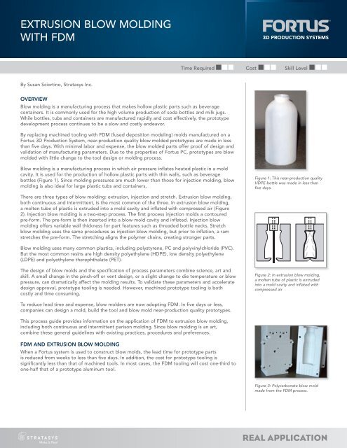
Blow molding is a manufacturing process in which air pressure infl ates heated plastic in a mold<br />
cavity. It is used for the production of hollow plastic parts with thin walls, such as beverage<br />
bottles (Figure 1). Since molding pressures are much lower than those for injection molding, blow<br />
molding is also ideal for large plastic tubs and containers.<br />
There are three types of blow molding: extrusion, injection and stretch. Extrusion blow molding,<br />
both continuous and intermittent, is the most common of the three. In extrusion blow molding,<br />
a molten tube of plastic is extruded into a mold cavity and infl ated with compressed air (Figure<br />
2). Injection blow molding is a two-step process. The fi rst process injection molds a contoured<br />
pre-form. The pre-form is then inserted into a blow mold cavity and infl ated. Injection blow<br />
molding offers variable wall thickness for part features such as threaded bottle necks. Stretch<br />
blow molding uses the same procedures as injection blow molding, but prior to infl ation, a ram<br />
stretches the pre-form. The stretching aligns the polymer chains, creating stronger parts.<br />
Blow molding uses many common plastics, including polystyrene, PC and polyvinylchloride (PVC).<br />
But the most common resins are high density polyethylene (HDPE), low density polyethylene<br />
(LDPE) and polyethylene therephthalate (PET).<br />
The design of blow molds and the specifi cation of process parameters combine science, art and<br />
skill. A small change in the pinch-off or vent design, or a slight change to die temperature or blow<br />
pressure, can dramatically affect the molding results. To validate these parameters and accelerate<br />
design approval, prototype tooling is needed. However, machined prototype tooling is both<br />
costly and time consuming.<br />
To reduce lead time and expense, blow molders are now adopting <strong>FDM</strong>. In fi ve days or less,<br />
companies can design a mold, build the tool and blow mold near-production quality prototypes.<br />
This process guide provides information on the application of <strong>FDM</strong> to extrusion blow molding,<br />
including both continuous and intermittent parison molding. Since blow molding is an art,<br />
combine these general guidelines with existing practices, procedures and preferences.<br />
<strong>FDM</strong> AND <strong>EXTRUSION</strong> <strong>BLOW</strong> <strong>MOLDING</strong><br />
When a <strong>Fortus</strong> system is used to construct blow molds, the lead time for prototype parts<br />
is reduced from weeks to less than fi ve days. In addition, the cost for prototype tooling is<br />
signifi cantly less than that of machined tools. In most cases, the <strong>FDM</strong> tooling will cost one-third to<br />
one-half that of a prototype aluminum tool.<br />
3D PRODUCTION SYSTEMS<br />
Time Required Cost Skill Level<br />
Figure 1: This near-production quality<br />
HDPE bottle was made in less than<br />
fi ve days.<br />
Figure 2: In extrusion blow molding,<br />
a molten tube of plastic is extruded<br />
into a mold cavity and infl ated with<br />
compressed air<br />
Figure 3: Polycarbonate blow mold<br />
made from the <strong>FDM</strong> process.<br />
REAL APPLICATION
<strong>EXTRUSION</strong> <strong>BLOW</strong> <strong>MOLDING</strong> PAGE 2<br />
The <strong>FDM</strong> process is unique in its use of thermoplastics, and it is this feature that provides the<br />
benefi ts of rapid tooling for blow molding. <strong>Fortus</strong> PC can withstand both the temperature and<br />
pressure of blow molding (Figure 3). With no wear or deformation, an <strong>FDM</strong> tool can produce<br />
hundreds, even thousands, of molded parts in common materials like HPDE, LDPE, PET, PVC, PC,<br />
polystyrene, and polyethylene (Figure 4).<br />
Unlike other prototype tooling methods, <strong>FDM</strong> requires only minor modifi cations to standard tool<br />
design and molding parameters. So, any prototype blow molding project can use <strong>FDM</strong> tools<br />
without radical changes to conventional practices. Shop effi ciency is maximized with the simple,<br />
unattended operation of a <strong>Fortus</strong> system. Skilled employees are freed up to tackle other projects<br />
while the <strong>FDM</strong> tool is being constructed.<br />
With <strong>FDM</strong> blow molds, prototype bottles and containers are produced quickly and affordably.<br />
The near-production quality of the molded parts expedites product and process analysis and<br />
customer design approval.<br />
APPLICATION BRIEFS<br />
Prototype Beverage Bottles<br />
A container manufacturer challenged Stratasys to reduce both cost and time for the<br />
development of blow molded prototypes. The goal was to decrease the time for prototyping<br />
near-production quality parts from several weeks to less than fi ve days.<br />
The company selected a six-inch tall, 3-inch diameter (152 x 76 mm) bottle for the pilot project.<br />
Using <strong>Fortus</strong> PC material for the tool cavity and a machined aluminum mold base, the blow<br />
mold was designed and built in only two days. With only minor changes to the tool design and<br />
molding process, the bottle was blow molded in BP Solvay Fortifl ex® HP 58, an HDPE. The<br />
entire process was completed in less than fi ve days, and the company stated that the molded<br />
prototypes met their criteria for near-production quality.<br />
Tool Life Analysis<br />
Using <strong>Fortus</strong> PC tooling, one manufacturer successfully blow molded 800 bottles in PET. Due to<br />
time constraints, and the desired quantity of prototypes, the testing was stopped after molding<br />
800 pieces. Inspection revealed that there was no wear, distortion or dimensional change to the<br />
<strong>FDM</strong> tool. The company concluded that an <strong>FDM</strong> blow mold could produce thousands of parts, if<br />
desired.<br />
PROCESS OVERVIEW<br />
Extrusion blow molding begins with heating of a plastic resin, typically between 350 and 500°F<br />
(175 - 260°C). The molten resin is then extruded through a die to create a round hollow tube<br />
of plastic called a parison. In continuous extrusion (Figure 5), the parison is clamped between<br />
the mold halves. As the mold closes on the parison, it pinches off and seals the tube of plastic.<br />
In intermittent extrusion (Figure 6), molten plastic fi lls an accumulator, and a ram extrudes the<br />
parison within the mold cavity.<br />
After the parison is extruded, it is pierced with a blow pin. Compressed air, typically 85 to 120<br />
psi (586 to 827 kPa), then infl ates the parison, which forces the plastic against the mold surface.<br />
The molded part is then cooled and ejected.<br />
PROCESS<br />
A <strong>Fortus</strong> PC tool, or tooling insert, replaces a machined blow mold, which is commonly made<br />
from aluminum, tool steel, stainless steel or beryllium copper. For prototype blow molding, the<br />
<strong>FDM</strong> tool eliminates the labor and expense needed to machine metal tools.<br />
TOOL DESIGN<br />
An <strong>FDM</strong> blow mold requires only minor modifi cation to standard tool design. The <strong>FDM</strong> mold<br />
incorporates the pinch-off, fl ash pocket, cooling system and mounting plate typical of a blow<br />
mold. However, in an <strong>FDM</strong> tool, vents are not added. Since the <strong>FDM</strong> cavity has a small amount<br />
of porosity, air trapped between the molded plastic and tool surface is vented through the body<br />
of the tool.<br />
The tool’s design is modifi ed to add a sloped, raised rib around the contour of the cavity. This<br />
rib acts as a compression seal between the mold halves, which gives clean shut-off and good<br />
pinch-off of the parison. In testing, a 0.125 in. wide (3.2 mm) rib that is 0.060 in. high (1.5 mm),<br />
has performed well when blow molding HDPE. The rib will have a slope, as shown in Figure 7,<br />
Figure 4: Prototype bottle molded<br />
in PET.<br />
Figure 5: Continuous extrusion blow<br />
molding. The parison is extruded<br />
through a die (left), and the mold<br />
closes on the tube of plastic. The<br />
parison is then infl ated (right) to force<br />
the plastic to the contours of the tool.<br />
Figure 6: Intermittent extrusion blow<br />
molding. The parison is extruded within<br />
the mold cavity (left) and infl ated with<br />
air pressure (right).
<strong>EXTRUSION</strong> <strong>BLOW</strong> <strong>MOLDING</strong> PAGE 3<br />
on its outer edge. These specifi cations may vary with part size, plastic selection and molding<br />
parameters, and therefore, adjustment may be needed.<br />
There are three tool design options. Selection of the best option balances the blow molding<br />
machines specifi cations, the needs of the molded part and personal preferences.<br />
1. <strong>FDM</strong> Tool: The entire tool is constructed with <strong>FDM</strong> (fi gure 8).<br />
2. Hybrid Tool - Block Insert: A rectangular <strong>FDM</strong> insert is paired with a pre-fabricated aluminum<br />
mold base.<br />
3. Hybrid Tool - Contoured Insert: An <strong>FDM</strong> insert that follows the contours of the molded part is<br />
paired with a pre-fabricated aluminum mold base (fi gure 9).<br />
To date, the best performance has been with hybrid-contoured <strong>FDM</strong> inserts.<br />
<strong>FDM</strong> TOOL DESIGN<br />
With the exception of venting and the addition of the perimeter rib, the tool is designed like<br />
any machined mold. Cooling channels may be constructed in the <strong>FDM</strong> tool, but it is simpler and<br />
faster to use a standard mounting plate with cooling lines.<br />
Hybrid Tool - Block Insert Design:<br />
Allow 0.5 in. (12.7 mm), at a minimum, around the periphery of the mold cavity. For example,<br />
a six-inch tall, three-inch diameter (152.4 x 76.2 mm) bottle would have two rectangular mold<br />
halves that measure 7 x 4 x 2 in. (177.8 x 101.6 x 50.8 mm).<br />
Mount the <strong>FDM</strong> inserts in a machined aluminum mold base that has a rectangular cavity with the<br />
same dimensions. To minimize the cost and time needed to make the mold bases, establish an<br />
inventory of standard sizes and design the <strong>FDM</strong> insert to fi t within one of these standards.<br />
Note that this design option may result in stress fractures. The aluminum mold base restrains<br />
the PC insert as it expands during blow molding. To avoid fractures, increase the duration of the<br />
cooling cycle.<br />
Hybrid Tool - Contoured Insert Design:<br />
For the face of the insert, allow 0.25 in. (6.4 mm), at a minimum, around the periphery of the<br />
mold cavity. Unlike the rectangular insert, each <strong>FDM</strong> insert will have a contoured back side<br />
(Figure 10). Following the contours of the molding surface, create a surface that is offset by at<br />
least 0.25 in. (6.4 mm).<br />
This tooling option offers the advantages of reduced material consumption and build time. It<br />
also reduces molding cycle time because the insert retains less heat.<br />
As with the rectangular inserts, make aluminum mold bases that are appropriate for the standard<br />
sizes of molded parts. These mold bases will have a rectangular cavity that holds the <strong>FDM</strong> insert.<br />
Since the insert is contoured, there will be an air gap between the back side of the <strong>FDM</strong> insert<br />
and the aluminum cavity.<br />
COOLING SYSTEM<br />
For the hybrid tools, use normal cooling channel design and incorporate the cooling system<br />
in the aluminum mold base. As stated previously, tools made entirely from <strong>FDM</strong> may have the<br />
cooling system in the PC tool or the mounting plate. To reduce cycle times, cooling lines may<br />
be supplemented with compressed air blown onto the face of the tool after ejection of the<br />
molded part.<br />
Although no design specifi cations are available, research on fl ood cooling is ongoing. To minimize<br />
cycle times, <strong>FDM</strong> tools or inserts are made hollow and coolant fl oods the internal chamber.<br />
TOOL CONSTRUCTION<br />
Orient the mold cavities such that the mold face (parting surface) is perpendicular to the<br />
Z-axis. Although the vertical orientation will add time to the build, it provides the best surface<br />
characteristics for the mold cavity and will yield the best shut off between the mold halves. With<br />
only one exception, construct the <strong>FDM</strong> molds using normal build parameters. The exception is<br />
Figure 7: A rib is added to the tool<br />
design. The rib follows the contours of<br />
the mold cavity.<br />
Figure 8: <strong>FDM</strong> blow molding tool made<br />
from polycarbonate.<br />
Figure 9: <strong>FDM</strong> hybrid tool with<br />
contoured inserts.<br />
Figure 10: CAD data for a contoured<br />
insert that is mounted in a machined<br />
mold base.
<strong>EXTRUSION</strong> <strong>BLOW</strong> <strong>MOLDING</strong> PAGE 4<br />
to use multiple contours along the cavity walls (Figure 11). Increasing the number of contours<br />
paths diminishes porosity in the mold to produce a better part.<br />
Note that ABS and PPSU/PPSF (polyphenolsulfone) are not suitable for blow mold tooling. ABS<br />
does not have the properties to withstand the temperature and pressure of blow molding.<br />
Although PPSU/PPSF is strong and heat resistance, it retains too much heat, which causes blow<br />
molded parts to stick to the tool. For these reasons, use only PC for blow molding.<br />
After building the <strong>FDM</strong> tool, remove all support structures and bead blast the cavity with plastic<br />
blast media. This simple and quick two-step process will produce a tooling surface that molds<br />
near-production quality parts.<br />
Prior to bead blasting the tool, mask off the parting surface and any sharp corners. Then place<br />
the tool in a bead blaster-loaded with plastic blast media-and spray the cavity of the tool using a<br />
pressure of 60 to 90 psi (414 to 621 kPa). For additional information, refer to the Bead Blasting<br />
Finishing Guide. Bead blasting eliminates all labor for sanding and fi lling while protecting<br />
dimensional accuracy. This simple procedure saves hours in manual labor for benching the<br />
tool cavities. The faces of the tools will not need any machining or hand work. The untouched<br />
surface provides good shut-off and minimal fl ash. The fi nal step is to mount the PC cavity in a<br />
pre-fabricated aluminum mold base. The tool is now ready for blow molding.<br />
<strong>BLOW</strong> <strong>MOLDING</strong><br />
Prototype blow molding (fi gures 12 & 13) requires only one change to the process. Since the PC<br />
cavities will retain heat, the cooling cycle is extended. The duration will vary by tool, part and<br />
molded plastic, so the cycle time is determined through experience and trial-and-error.<br />
Start with a cooling cycle that is fi ve times longer than that for a metal blow mold. If molding<br />
is successful, decrease the duration and repeat. Continue to decrease the cycle time until the<br />
molded part begins to stick. Return to the last successful molding cycle and begin blow molding<br />
the prototype parts.<br />
Tip: If the tool is not pinching off the parison, or if there is too much fl ash, add a shim between<br />
the PC cavity and aluminum mold base.<br />
Even though the cooling cycle is lengthened, the PC cavity temperature will continue to increase,<br />
and molded parts will begin to stick to the tool. When this happens, open the tool and allow<br />
it to return to operating temperature. Optionally, compressed air can be blown on the tool to<br />
accelerate the cooling process.<br />
After the prototype parts are blow molded, pinch-off material and fl ash are trimmed. The<br />
prototype blow molded parts are now complete and ready for review (Figure 14).<br />
CONCLUSION<br />
Using these process guidelines, <strong>FDM</strong> can overcome the obstacles to prototyping, namely time<br />
and cost. Delivery of molded prototypes is slashed by 50 to 75 percent and the cost of the<br />
prototype tooling is reduced by 50 to 60 percent.<br />
Since <strong>FDM</strong> tooling replaces conventional tooling with only minor design and process changes,<br />
this prototyping technique is easily incorporated within any blow molding operation. Nearproduction<br />
quality and a broad selection of blow molding materials make <strong>FDM</strong> an ideal choice<br />
for any blow molding project. Both quick and affordable, <strong>FDM</strong> expedites product and process<br />
analysis and customer design approval.<br />
Figure 11: To mold the PET bottle, this<br />
hybrid insert uses a cylindrical design.<br />
Figure 12: Increasing the number of<br />
contour passes reduces porosity and<br />
improves part quality.<br />
Figure 13: Prototype hybrid <strong>FDM</strong> tool<br />
mounted in blow molding machine.<br />
Figure 14: Prototype hybrid <strong>FDM</strong> tool<br />
opens and HDPE bottle is ejected.
<strong>EXTRUSION</strong> <strong>BLOW</strong> <strong>MOLDING</strong> PAGE 5<br />
For more information about <strong>Fortus</strong> systems, materials and applications, call 888.480.3548 or visit www.fortus.com<br />
<strong>Fortus</strong> 3D Production Systems<br />
Stratasys Incorporated<br />
7665 Commerce Way<br />
Eden Prairie, MN 55344<br />
+1 888 480 3548 (US Toll Free)<br />
+1 952 937 3000<br />
+1 952 937 0070 (Fax)<br />
www.stratasys.com<br />
info@stratasys.com<br />
<strong>Fortus</strong> 3D Production Systems<br />
Stratasys GmbH<br />
Weismüllerstrasse 27<br />
60314 Frankfurt am Main<br />
Germany<br />
+49 69 420 9943 0 (Tel)<br />
+49 69 420 9943 33 (Fax)<br />
www.stratasys.com<br />
europe@stratasys.com<br />
©2009 Stratasys Inc. All rights reserved. Stratasys and <strong>FDM</strong> are registered trademarks and <strong>Fortus</strong>, Real Parts, <strong>Fortus</strong> 200mc, <strong>Fortus</strong> 360mc,<br />
<strong>Fortus</strong> 400mc, <strong>Fortus</strong> 900mc, Insight, Control Center and <strong>FDM</strong> TEAM are trademarks of Stratasys Inc., registered in the United States and<br />
other countries. *ULTEM 9085 is a trademark of SABIC Innovative Plastics IP BV. All other trademarks are the property of their respective<br />
owners. Product specifi cations subject to change without notice. Printed in the USA. AG-EXT <strong>BLOW</strong> 01/09<br />
<strong>FDM</strong> PROCESS DESCRIPTION<br />
<strong>Fortus</strong> 3D Production Systems<br />
are based on patented Stratasys<br />
<strong>FDM</strong> (Fused Deposition Modeling)<br />
technology. <strong>FDM</strong> is the industry’s<br />
leading Additive Fabrication<br />
technology, and the only one<br />
that uses production grade<br />
thermoplastic materials to build<br />
the most durable parts direct from<br />
3D data. <strong>Fortus</strong> systems use the<br />
widest range of advanced materials<br />
and mechanical properties so your<br />
parts can endure high heat, caustic<br />
chemicals, sterilization, high impact<br />
applications.<br />
The <strong>FDM</strong> process dispenses two<br />
materials—one material to build<br />
the part and another material for<br />
a disposable support structure.<br />
The material is supplied from a roll<br />
of plastic fi lament on a spool. To<br />
produce a part, the fi lament is fed<br />
into an extrusion head and heated<br />
to a semi-liquid state. The head<br />
then extrudes the material and<br />
deposits it in layers as fi ne as 0.005<br />
inch (0.127 mm) thick.<br />
Unlike some Additive Fabrication<br />
processes, <strong>Fortus</strong> systems with<br />
<strong>FDM</strong> technology require no<br />
special facilities or ventilation and<br />
involve no harmful chemicals and<br />
by-products.
