


You also want an ePaper? Increase the reach of your titles
YUMPU automatically turns print PDFs into web optimized ePapers that Google loves.
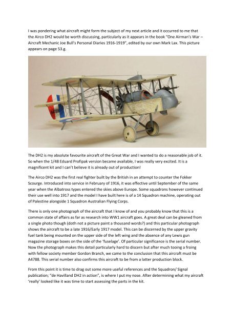
I was pondering what aircraft might form the subject of my next article and it occurred to me that<br />
the <strong>Airco</strong> <strong>DH</strong>2 would be worth discussing, particularly as it appears in the book “One Airman’s War –<br />
Aircraft Mechanic Joe Bull’s Personal Diaries 1916-1919”, edited by our own Mark Lax. This picture<br />
appears on page 53.g.<br />
The <strong>DH</strong>2 is my absolute favourite aircraft of the Great War and I wanted to do a reasonable job of it.<br />
So when the 1/48 Eduard Profipak version became available, I was really very excited. It is a<br />
magnificent kit and I can’t believe it is already out of production!<br />
The <strong>Airco</strong> <strong>DH</strong>2 was the first real fighter built by the British in an attempt to counter the Fokker<br />
Scourge. Introduced into service in February of 1916, it was effective until September of the same<br />
year when the Albatross types entered the skies above Europe. Some squadrons however continued<br />
their use well into 1917 and the model I have built here is of a 14 Squadron machine, operating out<br />
of Palestine alongside 1 Squadron Australian Flying Corps.<br />
There is only one photograph of the aircraft that I know of and you probably know that this is a<br />
common state of affairs as far as research into WW1 aircraft goes. A great deal can be gleaned from<br />
a single photo though (doth not a picture paint a thousand words?) and this particular photograph<br />
shows the aircraft to be a late 1916/Early 1917 model. This can be discerned by the upper gravity<br />
fuel tank being mounted on the upper side of the left wing and the absence of any Lewis gun<br />
magazine storage boxes on the side of the ‘fuselage’. Of particular significance is the serial number.<br />
Now the photograph makes this detail particularly hard to discern but after much tooing a froing<br />
with fellow society member Gordon Branch, we came to the conclusion that this aircraft must be<br />
A4788. This serial number also confirms this aircraft to be from a latter production block.<br />
From this point it is time to drag out some more useful references and the Squadron/ Signal<br />
publication; “de Havilland <strong>DH</strong>2 in action”, is where I put my nose. After determining what my aircraft<br />
‘really’ looked like it was time to start assessing the parts in the kit.
The most significant changes I have made to this kit involve the<br />
fuselage or nacelle. This has very finely raised details on the<br />
inside to represent the timber spars that form the structural<br />
framework of the nacelle. Because the kit lacks any plumbing<br />
details, which I wanted to represent, these wooden elements<br />
had to be bulked up with plastic strip so that the<br />
plumbing/wiring could be added and at least have the<br />
appearance of passing behind this framework. These strips were<br />
added and the plumbing/wiring installed as per the few hints<br />
provided in the images in the Squadron book.<br />
The kit provides three instrument panels. I have chosen the third<br />
option as the drawings from the “Squadron <strong>DH</strong>2 in action” book show<br />
this arrangement to be typical of aircraft from this period. This<br />
required some dressing up and I scratch built pulsometers, a pressure<br />
gauge and a “fine adjustment regulator” from items in the spares box.<br />
A few other cockpit details were also added. The control column<br />
(joystick) and rudder pedals were rigged with the appropriate cables.<br />
A padded edge was added to the photo etched cockpit seat which<br />
consists of a strand of very thin solder which drapes itself nicely along<br />
the edge of the seat.<br />
Next, the nacelle comes with the side panels being perfectly<br />
flat which is well and good but I wanted this aircraft to look<br />
a little more lived in. To replicate the sort of<br />
stretching/sagging typical of this sort of aircraft, these<br />
panels were worked with dentist’s chisels. I have seen this<br />
sort of work done with fine strips of putty, and this might<br />
be a better solution if you don’t fancy hacking into the<br />
nacelle with chisels. Milliput is great because if you really<br />
stuff up, you can wash the stuff away completely (before is<br />
has cured of course) with no damage to the kit pieces.<br />
The engine is a real gem, however the engine push rods (part B13)<br />
were replaced with individually stretched sprue rods. If the kit part<br />
was used, these rods would have been approximately 5cm thick! If<br />
you are not into fiddley details then steer clear of the Photo<br />
etched pieces. All in all, this engine is made up of about 30 parts<br />
and I wish I had a dozen such engines in my spares box. I have<br />
added a lot of other details such as ignition leads, spark plugs and
some other gear forward of the engine that you can barely see so it is up to you whether you add<br />
these details.<br />
One of the steps involved in building the nacelle is the addition of the engine mount. When gluing<br />
this piece in, dry fit the engine to set up the correct angle – you don’t want the engine interfering<br />
with the rear of the nacelle. Don’t be tempted to fit the engine too early; it will get in the way of<br />
other jobs. Wait until the wings, the rear booms and landing gear go on.<br />
The fuel tank was relocated as per the photo of the original aircraft. Plumbing was made from wire<br />
to suit. A vent for this tank was made from wire. Note that no sight gauge was present on later<br />
aircraft.<br />
The propeller was painted in artist’s oils – a combination of<br />
yellow ochre and burnt sienna. A stiff brush will help in<br />
reproducing a grain effect, but don’t overdo this – grain is<br />
barely discernable even in 1/48 scale. In reality, I have<br />
probably overdone the effect on my model. Painting wood<br />
grain is another subject which can be discussed in detail in<br />
another article and there are a number of quick and dirty<br />
solutions as well as techniques that look just like the real<br />
thing which you can apply to your models.<br />
The photo etched pullies for the rudder were located on the correct side of the inner interplane<br />
struts. The instructions in step 6 show that the pullies should be fitted on the inside of the struts, but<br />
photo’s and the drawings from the Squadron book show that these pullies in fact are on the outside<br />
of the struts.<br />
The boom assemblies had the longitudinal plastic rods<br />
replaced with brass rods. When rigging up an aircraft like<br />
this, a certain amount of tension is required to prevent sag.<br />
This tension can easily deform a fragile structure and so<br />
brass provides a little stiffness. Note that the vertical struts<br />
between the upper and lower booms have an aerofoil<br />
section that lies parallel to the air flow, not parallel to the<br />
booms. If you do replace the plastic rods with brass, make a<br />
jig to enable you to put them back together in exactly the<br />
same shape.<br />
The rudder control cable exits the side of the fuselage from a point further aft than on earlier<br />
aircraft. This hole was relocated as per the Squadron drawings. Rigging for the rudder and tail skid<br />
assembly is incorrect in the kit instructions. These were rigged utilising a splitter plate to divide the<br />
cable into two runs – one for the rudder, one for the tail skid. This should be apparent from the<br />
photo’s. I made this splitter plate from a scrap of plastic card but I would prefer to have used a<br />
photo-etched piece – maybe one day I will make one.
A hinged panel was added to the left hand side of the engine<br />
nacelle as per the Squadron drawings of late 1916 aircraft.<br />
On my model, I haven’t actually added anything and the<br />
panel is actually just painted on as an outline in sepia ink.<br />
This could also be done by scribing an outline into the<br />
nacelle.<br />
Bungee suspension was added to landing gear with knitting<br />
in elastic. This particular brand of elastic, Madeira – made in<br />
Germany, has a thin weave of nylon covering it giving it an<br />
interesting texture.<br />
The upper nacelle panel into which the cabane struts will<br />
go will benefit from the holes for these struts being<br />
opened out slightly to accommodate them. This panel also<br />
has some photo-etched brass belts which require fitting.<br />
The instructions state to remove the plastic belts which<br />
are moulded into this part and then fit the photo-etched<br />
belt and its buckle. I just removed the plastic buckles and<br />
fit the photo-etched buckles on top of the plastic belts.<br />
Much easier!<br />
Clear doped linen appears to be the overall colour scheme<br />
for 14SQN Aircraft. My previous article on CDL covers how I did this, although on this model, the<br />
upper surfaces were treated in the same fashion as the lower surfaces. If I were to make this model<br />
again, I would go with the method in my previous article..<br />
The aircraft is rigged with a mixture of EZ-line (a type of elastic which I believe is available through<br />
Red Roo Models in Australia), monofilament nylon and stretched sprue. Aileron cables and pullies<br />
were added to the upper surface of the upper wing as per the Squadron drawing for later aircraft.<br />
Turn barrels have simply been rendered by painting gold and silver sections directly onto the various<br />
cables.<br />
Last but not least, the Lewis gun is a very nice piece which<br />
with the addition of the photo-etched parts comes up very<br />
nicely. To make the spade grip a little more convincing,<br />
fatten it up with several layers of superglue.<br />
Anyway, when all is said and done, I found this a very<br />
fulfilling build and well worth the many, many hours it took<br />
to get to this result. Whilst the Eduard kit may be out of<br />
production, I am sure you could find it second hand somewhere. (I bet a lot of you have one in your<br />
stash!) I am also confident it will see a reissue at some stage in the future – it is too great a kit to<br />
disappear altogether.<br />
If you have any questions, don’t hesitate to drop me a line. Carpo1@iprimus.com.au<br />
Paul Carpenter………..All photos courtesy of Paul Carpenter.
