Boiler Manual
Boiler Manual
Boiler Manual

You also want an ePaper? Increase the reach of your titles
YUMPU automatically turns print PDFs into web optimized ePapers that Google loves.
14<br />
HEATING SYSTEM PIPING<br />
Cast Iron Condensing <strong>Boiler</strong>s – Installation <strong>Manual</strong><br />
General Piping Requirements<br />
All heating system piping must be installed by a qualifi ed<br />
technician in accordance with the latest revision of the<br />
ANSI/ASME <strong>Boiler</strong> and Pressure Vessel Code, Section IV.<br />
Where required, the piping must comply with ANSI/<br />
ASME CSD-1, Standard for Controls and Safety Devices<br />
for Automatically Fired <strong>Boiler</strong>s.<br />
All applicable local codes and ordinances must also be<br />
followed. A minimum clearance of 1in, 25 mm must be<br />
maintained between heating system pipes and all<br />
combustible construction. All heating system piping must<br />
be supported by suitable hangers, not the boiler. The<br />
thermal expansion of the system must be considered<br />
when supporting the system. A minimum system<br />
pressure of 12 psig, 84 kPa must be maintained at<br />
boiler operating conditions. A minimum system pressure<br />
of 25 psig, 172 kPa fi ll pressure is required, at boiler<br />
operating conditions on glycol mixtures within a closed<br />
loop.<br />
Cleaning, Flushing System<br />
Prior to commissioning the boiler/s, the piping/system<br />
must be cleaned and fl ushed to prevent contaminants<br />
from settling back into the boiler and fouling the heat<br />
exchanger. Isolate the boiler from the system prior to<br />
the cleaning process. Fill the system with water, add<br />
the cleaning solution and circulate per the chemical<br />
supplier’s instructions until the system TDS is within<br />
10% of the city water TDS. Add the corrosion inhibitor<br />
to the system and follow the chemical supplier’s<br />
instructions.<br />
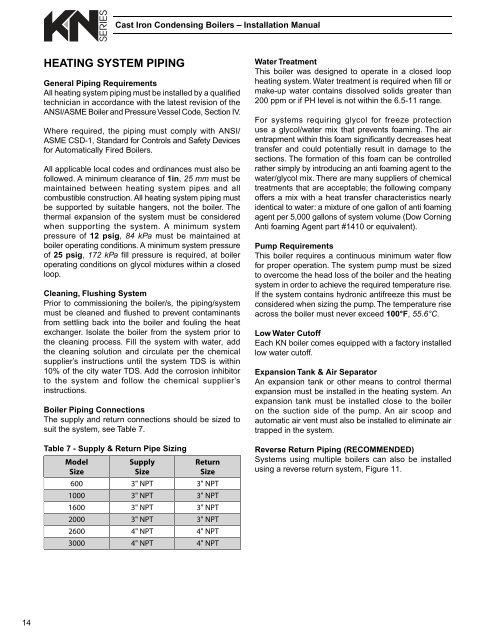
<strong>Boiler</strong> Piping Connections<br />
The supply and return connections should be sized to<br />
suit the system, see Table 7.<br />
Table 7 - Supply & Return Pipe Sizing<br />
Model<br />
Size<br />
Supply<br />
Size<br />
Return<br />
Size<br />
600 3" NPT 3" NPT<br />
1000 3" NPT 3" NPT<br />
1600 3" NPT 3" NPT<br />
2000 3" NPT 3" NPT<br />
2600 4" NPT 4" NPT<br />
3000 4" NPT 4" NPT<br />
Water Treatment<br />
This boiler was designed to operate in a closed loop<br />
heating system. Water treatment is required when fi ll or<br />
make-up water contains dissolved solids greater than<br />
200 ppm or if PH level is not within the 6.5-11 range.<br />
For systems requiring glycol for freeze protection<br />
use a glycol/water mix that prevents foaming. The air<br />
entrapment within this foam signifi cantly decreases heat<br />
transfer and could potentially result in damage to the<br />
sections. The formation of this foam can be controlled<br />
rather simply by introducing an anti foaming agent to the<br />
water/glycol mix. There are many suppliers of chemical<br />
treatments that are acceptable; the following company<br />
offers a mix with a heat transfer characteristics nearly<br />
identical to water: a mixture of one gallon of anti foaming<br />
agent per 5,000 gallons of system volume (Dow Corning<br />
Anti foaming Agent part #1410 or equivalent).<br />
Pump Requirements<br />
This boiler requires a continuous minimum water fl ow<br />
for proper operation. The system pump must be sized<br />
to overcome the head loss of the boiler and the heating<br />
system in order to achieve the required temperature rise.<br />
If the system contains hydronic antifreeze this must be<br />
considered when sizing the pump. The temperature rise<br />
across the boiler must never exceed 100°F, 55.6°C.<br />
Low Water Cutoff<br />
Each KN boiler comes equipped with a factory installed<br />
low water cutoff.<br />
Expansion Tank & Air Separator<br />
An expansion tank or other means to control thermal<br />
expansion must be installed in the heating system. An<br />
expansion tank must be installed close to the boiler<br />
on the suction side of the pump. An air scoop and<br />
automatic air vent must also be installed to eliminate air<br />
trapped in the system.<br />
Reverse Return Piping (RECOMMENDED)<br />
Systems using multiple boilers can also be installed<br />
using a reverse return system, Figure 11.