BERMAD Fire Protection
BERMAD Fire Protection
BERMAD Fire Protection

Create successful ePaper yourself
Turn your PDF publications into a flip-book with our unique Google optimized e-Paper software.
<strong>BERMAD</strong> <strong>Fire</strong> <strong>Protection</strong><br />
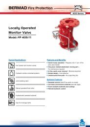
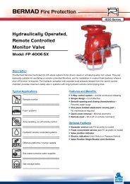
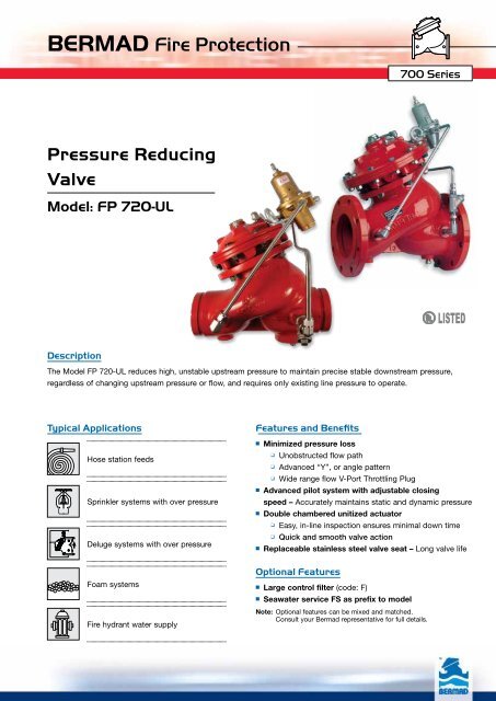
Pressure Reducing<br />
Valve<br />
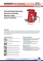
Model: FP 720-UL<br />
Description<br />
Typical Applications Features and Benefits<br />
700 Series<br />
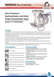
The Model FP 720-UL reduces high, unstable upstream pressure to maintain precise stable downstream pressure,<br />
regardless of changing upstream pressure or flow, and requires only existing line pressure to operate.<br />
Hose station feeds<br />
Sprinkler systems with over pressure<br />
Deluge systems with over pressure<br />
Foam systems<br />
<strong>Fire</strong> hydrant water supply<br />
■ Minimized pressure loss<br />
❑ Unobstructed flow path<br />
❑ Advanced “Y”, or angle pattern<br />
❑ Wide range flow V-Port Throttling Plug<br />
■ Advanced pilot system with adjustable closing<br />
speed – Accurately maintains static and dynamic pressure<br />
■ Double chambered unitized actuator<br />
❑ Easy, in-line inspection ensures minimal down time<br />
❑ Quick and smooth valve action<br />
■ Replaceable stainless steel valve seat – Long valve life<br />
Optional Features<br />
■ Large control filter (code: F)<br />
■ Seawater service FS as prefix to model<br />
Note: Optional features can be mixed and matched.<br />
Consult your Bermad representative for full details.
<strong>BERMAD</strong> <strong>Fire</strong> <strong>Protection</strong><br />
Model: FP 720-UL<br />
Operation<br />
Valve Closed (static condition) Valve Open (flowing condition)<br />
Engineer Specifications<br />
700 Series<br />
The <strong>BERMAD</strong> Model FP 720-UL, pilot operated pressure reducing valve automatically and accurately reduces<br />
downstream water pressure to a specific, adjustable value. The FP 720-UL operates under both flowing and nonflowing<br />
(static) conditions. The Pressure Reducing Pilot [1] senses downstream pressure [2] and in real time modulates<br />
the main valve [3] to maintain a constant downstream pressure.<br />
In no-flow static conditions, should the downstream pressure start rising above pilot setting, the pilot closes, shutting<br />
the main valve drip-tight sealing [4] to maintain the allowable downstream pressure.<br />
[4]<br />
The Pressure Reducing Valve shall be UL Listed for fire protection. It shall eliminate downstream over-pressure,<br />
maintaining a constant downstream delivery pressure, regardless of varying pressures and/or flows.<br />
The main valve shall be a diaphragm actuated, “Y” pattern (or angle) valve.<br />
Valve actuation shall be accomplished by one moving assembly containing a double chambered actuator, which shall<br />
include a stainless steel stem and a resilient elastomeric seal held by a flat seal disk and creating a drip tight seal<br />
against the seat.<br />
The valve seat shall be removable and made of stainless steel. The seat bore net area shall be no less than that of the<br />
valve nominal diameter and shall have an unobstructed flow path with no stem guide or supporting ribs.<br />
All necessary inspection and servicing shall be possible in-line.<br />
The valve shall be UL-Listed as a pressure controlling water control valve.<br />
The Pressure Reducing Pilot Valve shall be UL-Listed as part of the assembly.<br />
The control trim shall be supplied as an assembly, pre-assembled and hydraulically tested at an<br />
ISO 9000 and 9001 certified factory.<br />
[3]<br />
[1]<br />
[2]
<strong>BERMAD</strong> <strong>Fire</strong> <strong>Protection</strong><br />
Model: FP 720-UL<br />
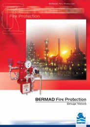
Typical Installations<br />
Standard<br />
Pressure Reducing<br />
System<br />
Parallel<br />
Pressure Reducing<br />
System<br />
■ Wide flow range<br />
■ Redundant safety<br />
■ Serviceable with zero down time<br />
Two-Stage<br />
Pressure Reducing<br />
System<br />
■ High pressure differential<br />
■ Added reduced pressure<br />
zone protection<br />
Installation Considerations<br />
4<br />
System Components<br />
1 - <strong>BERMAD</strong> Model FP 720-UL<br />
700 Series<br />
2 - Pressure Relief Valve (<strong>BERMAD</strong> Model FP 730-UF)<br />
3 - Isolating Valve<br />
4 - Pressure Gauge<br />
5 - Strainer<br />
1 2<br />
■ Allow enough room around the valve assembly for any future maintenance.<br />
■ Install isolating valves upstream and downstream of the valve system.<br />
■ Install the valve horizontally with the cover facing up.<br />
■ Install a UL-Listed relief valve (recommended: <strong>BERMAD</strong> Model FP 730-UF) of the appropriate<br />
size on the downstream side of the FP 720-UL, as required by NFPA-20 standard.<br />
■ Install a UL-Listed pressure gauge on both sides of the valve.<br />
UL Listed<br />
The <strong>BERMAD</strong> Model FP 720-UL is UL-Listed when installed as a unit.<br />
3<br />
5<br />
3<br />
4
<strong>BERMAD</strong> <strong>Fire</strong> <strong>Protection</strong><br />
Model: FP 720-UL<br />
Technical Data<br />
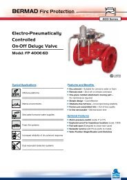
Dimensions<br />
Th<br />
R 1<br />
R 2<br />
R 3<br />
Connection Standard<br />
• Grooved: ANSI/AWWA C606 for 2, 3, 4, 6 & 8”<br />
• Flanged: ANSI B16.42 (Ductile Iron),<br />
B16.5 (Steel & Stainless Steel),<br />
B16.24 (Bronze), ISO PN16<br />
• Threaded: NPT or BSP 2, 2½ & 3”<br />
Water Temperature<br />
• 0.5 - 80°C (33 - 180°F)<br />
Manufacturers Standard Materials<br />
Main valve body and cover<br />
• Ductile Iron ASTM A-536<br />
Main valve internals<br />
• Stainless Steel & Elastomer<br />
Control Trim System<br />
• Brass control components/accessories<br />
• Stainless Steel 316 tubing & fittings<br />
Elastomers<br />
• Polyamide fabric reinforced Polyisoprene, NR<br />
Coating<br />
• Electrostatic Powder Coating Polyester,<br />
Red (RAL 3002)<br />
Ly 1 , Ly 2 , Ly 3<br />
Tw<br />
Sizes (“Y” & Angle)<br />
• Available Y: 1½ - 20”<br />
• Angle: 1½ – 18”<br />
• 24-36” Globe<br />
• UL-Listed: 2, 2½, 3, 4, 6 & 8”<br />
Optional Materials<br />
Main valve body/internals<br />
• Carbon Steel ASTM A-216-WCB<br />
• Stainless Steel 316<br />
• Ni-Al-Bronze ASTM B-148<br />
• Titanium<br />
• Duplex<br />
• Hastalloy<br />
Control Trim<br />
• Stainless Steel 316<br />
• Monel® and Al-Bronze<br />
• Hastalloy C-276<br />
Coating<br />
• High Build Epoxy Fusion-Bonded<br />
with UV <strong>Protection</strong>, Anti-Corrosion<br />
Th<br />
h 1<br />
h 2<br />
h 3<br />
Tw<br />
La 1 , La 2 , La 3<br />
Size<br />
1½”<br />
mm inch<br />
2”<br />
mm inch<br />
2½”<br />
mm inch<br />
3”<br />
mm inch<br />
4”<br />
mm inch<br />
6”<br />
mm inch<br />
8”<br />
mm inch<br />
10”<br />
mm inch<br />
12”<br />
mm inch<br />
14”<br />
mm inch<br />
16”<br />
mm inch<br />
(1) Ly1 205 1 8 /16 205 1 8 /16 209 1 8 /4 250 7 9 /8 320 5 12 /8 415 3 16 /8<br />
11 500 19 /16<br />
13 605 23 /16 725 9 28 /16 733 7 28 /8 990 39<br />
(2) Ly2 155 1 6 /8 155 1 6 /8 212 3 8 /8 250 13 9 /16 N/A N/A N/A N/A N/A N/A N/A N/A N/A N/A N/A N/A N/A N/A<br />
(3) Ly3 210 1 8 /4 210 1 8 /4 212 3 8 /8 264 7 10 /16 335 1 13 /4 433 1 17 /16 524 5 20 /8 637 25 762 30 767 3 3 30 /16 1,024 40 /4<br />
(1) La1 121 3 4 /4 121 3 4 /4 140 1 5 /2 152 6 190 1 7 /2 225 7 8 /8 265 7 10 /16 320 5 12 /8 396 9 15 /16 400 3 15 /4 450 3 17 /4<br />
(2) La2 120 3 4 /4 120 3 4 /4 140 1 5 /2 159 1 6 /4 N/A N/A N/A N/A N/A N/A N/A N/A N/A N/A N/A N/A N/A N/A<br />
(3) La3 127 5 127 5 149 7 5 /8 159 1 6 /4 200 7 7 /8 234 3 9 /16 277 7 10 /8 336 1 13 /4 415 5 16 /16 419 1 16 /2 467 3 18 /8<br />
(1) h1 82 31 /4 82 31 /4 102 4 102 4 127 5 152 6 203 8 219 85 /8 275 1013 /16 275 1013 /16 369 141 /2<br />
(2) h2 82 31 /4 82 31 /4 102 4 114 41 /2 N/A N/A N/A N/A N/A N/A N/A N/A N/A N/A N/A N/A N/A N/A<br />
(3) h3 89 31 /2 89 31 /2 109 45 /16 108 41 /4 135 55 /16 165 61 /2 216 81 /2 235 91 /4 294 111 /2 294 111 /2 386 53 /16<br />
(1) R1 75 215 /16 83 31 /4 93 35 /8 100 315 /16 114 41 /2 140 51 /2 171 63 /4 203 8 241 91 /2 267 101 /2 298 113 /4<br />
(2) R2 40 19 /16 40 19 /16 48 17 /8 55 21 N/A N/A N/A N/A N/A N/A N/A N/A N/A N/A N/A N/A N/A N/A<br />
(3) R3 78 31 /16 83 31 /4 95 33 /4 108 41 /4 127 5 159 61 /4 191 71 /2 222 83 /4 260 101 /4 292 111 /2 324 123 /4<br />
Tw 191 71 /2 191 71 /2 191 71 /2 207 81 /16 242 91 /2 290 117 /16 325 1213 /16 370 149 /16 515 201 /4 525 2011 /16 610 24<br />
Th 312 125 /16 312 125 /16 312 125 /16 364 141 /2 405 15 15 /16 505 20 566 225 /16 639 253 /16 449 1711 /16 449 1711 /16 541 215 /16<br />
Notes:<br />
1. Ly for ANSI#150, ISO PN16 & Grooved ends (see available sizes below)<br />
1<br />
2. La & h for Angle body, ANSI#150 and ISO PN16.<br />
1 1<br />
3. Ly , La & h for threaded female, NPT or BSP.<br />
2 2 2<br />
4. Ly , La & h for flanged ANSI #300 and ISO PN25.<br />
3 3 3<br />
5. Data is for maximum envelope dimensions, component positioning may vary.<br />
6. Provide adequate space around valve for maintenance.<br />
bermadfire@bermad.com • www.bermad.com<br />
The information herein is subject to change without notice. <strong>BERMAD</strong> shall not be held<br />
liable for any errors. All rights reserved. © Copyright by <strong>BERMAD</strong>. PE7PE-2UL 11<br />
700 Series<br />
Pressure Rating<br />
• UL-Listed 2 - 6” : 300 psi (21 bar)<br />
8” to : 175 psi (12 bar)<br />
• Max. for Class#150: 250 psi (17 bar)<br />
• Max. for Class#300: 400 psi (28 bar)<br />
• Max. for Grooved ends: 400 psi (28 bar)<br />
• Setting range: 30 - 165 psi (2 - 11.5 bar)<br />
• Test pressure: 450 psi (31 bar)<br />
Approvals<br />
• UL Listed for:<br />
Special system water control<br />
valves (VLMT), Pressure Reducing<br />
and Pressure Control type<br />
for <strong>Fire</strong> <strong>Protection</strong> Systems.<br />
• ABS<br />
• Lloyd’s Registered