H-Stud Area Separation Wall System - National Gypsum Company
H-Stud Area Separation Wall System - National Gypsum Company
H-Stud Area Separation Wall System - National Gypsum Company

Create successful ePaper yourself
Turn your PDF publications into a flip-book with our unique Google optimized e-Paper software.
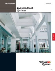
12 TH EDITION<br />
H-<strong>Stud</strong> <strong>Area</strong> <strong>Separation</strong> Wa l<br />
<strong>System</strong><br />
09 21 16.33/NGC<br />
®<br />
139<br />
09 21 16.33
H-STUD AREA SEPARATION WALL SYSTEM<br />
The fire-protection of gypsum-based <strong>Area</strong> <strong>Separation</strong> <strong>Wall</strong>s is demonstrated in dramatic fashion<br />
by the results of this actual townhouse fire in which the two-hour fire-rated assembly performed<br />
as expected in protecting adjacent properties. Break-away feature allowed collapse of fire-side<br />
structural framing without pulling down the entire wall.<br />
DESCRIPTION<br />
SOLID TYPE AREA<br />
SEPARATION WALL<br />
The H-<strong>Stud</strong> <strong>Area</strong> <strong>Separation</strong><br />
<strong>Wall</strong> consists of 2" lightgauge<br />
steel H-<strong>Stud</strong>s which<br />
secure two layers of 1" Fire-<br />
Shield Shaftliner or 1" Fire-<br />
Shield Shaftliner XP board<br />
between adjacent studs.<br />
Shaftliner board is faced with<br />
green moisture-resistant<br />
paper and Shaftliner XP<br />
board is faced with purple<br />
moisture/mold/mildewresistant<br />
paper on both<br />
sides for protection against<br />
weather during installation.<br />
Shaftliner panels have a<br />
beveled edge configuration<br />
allowing for simple<br />
installation into the H-<br />
<strong>Stud</strong>s.<br />
The H-<strong>Stud</strong>s are secured at the<br />
foundation floor by the<br />
flanges of H-<strong>Stud</strong> Track.<br />
The same track is used<br />
back-to-back at<br />
intermediate floors to<br />
provide a splicing means<br />
so that the <strong>System</strong> can be<br />
erected one floor at a time.<br />
H-<strong>Stud</strong> Track is also used at<br />
the roof line or at the<br />
parapet and at wall ends.<br />
For a fire-rated assembly<br />
without the need for<br />
battens, a minimum 3/4"<br />
air space shall be<br />
maintained between<br />
the H-<strong>Stud</strong> assembly and<br />
any adjacent framing<br />
members. When a 3/4"<br />
air space cannot be<br />
maintained, the H-<strong>Stud</strong><br />
and H-<strong>Stud</strong> Tracks are<br />
covered by screw-attached<br />
6" wide battens fabricated<br />
from 1/2" Fire-Shield C<br />
<strong>Gypsum</strong> Board; or 1/2"<br />
Fire-Shield C <strong>Gypsum</strong><br />
Board boards can be<br />
fastened to the H-<strong>Stud</strong>s<br />
and joints* covered with<br />
tape and joint compound<br />
to provide a finished wall.<br />
Mineral wool or glass fiber<br />
can be installed in<br />
adjacent cavity shaftwalls<br />
to provide higher STC<br />
ratings.<br />
Steel H-<strong>Stud</strong> framing<br />
members are attached on<br />
each side to adjacent<br />
framing with breakaway,<br />
heat softenable aluminum<br />
ASW Clips.<br />
*Refer to UL Design U347.<br />
NOTE: ICC ES Inc. Legacy<br />
Report 90-26.01 requires a<br />
1" minimum air space.<br />
TECHNICAL DATA<br />
1. <strong>Area</strong> <strong>Separation</strong> <strong>Wall</strong>s are<br />
nonload-bearing walls.<br />
They should not be used<br />
where exposed to constant<br />
dampness and/or water.<br />
140 H-STUD AREA SEPARATION WALL SYSTEM<br />
Steel framing and XP<br />
<strong>Gypsum</strong> Board products<br />
permit temporary exposure<br />
to inclement weather<br />
during construction, but<br />
the constructed <strong>Area</strong><br />
<strong>Separation</strong> <strong>Wall</strong> should be<br />
protected from inclement<br />
weather as soon as<br />
possible. Materials<br />
supplied to the job site<br />
should be stored properly,<br />
supported off the ground<br />
and protected from<br />
inclement weather.<br />
TYPICAL FLOOR/CEILING JUNCTURE<br />
DOUBLE H-STUD TRACK<br />
(back to back)<br />
FLOOR<br />
FIRE BLOCKING<br />
1" FIRE-SHIELD<br />
SHAFTLINER OR<br />
MINERAL WOOL<br />
ASW CLIP<br />
H-STUD<br />
2. The <strong>Area</strong> <strong>Separation</strong> <strong>Wall</strong><br />
<strong>System</strong> may be built up to<br />
a maximum of 66' high.<br />
3. Insulation in the <strong>Area</strong><br />
<strong>Separation</strong> <strong>Wall</strong> must be<br />
protected from wetting and<br />
therefore shall not be<br />
installed until building is<br />
closed-in.<br />
4. XP <strong>Gypsum</strong> Board or<br />
<strong>Gypsum</strong> Sheathing shall<br />
be used on faces of stud<br />
framing of <strong>Area</strong> <strong>Separation</strong><br />
<strong>Wall</strong>s which project<br />
beyond roof or side walls.<br />
3/4" AIR SPACE STUD<br />
1" FIRE-SHIELD<br />
SHAFTLINER<br />
TRIM<br />
CEILING<br />
GYPSUM<br />
BOARD<br />
STRINGER<br />
TOP PLATE
AREA SEPARATION WALL LIMITING HEIGHTS<br />
66'<br />
<strong>Wall</strong>s up to 66' space<br />
clips a maximum of<br />
39" o.c. for wall sections<br />
below the upper 54'<br />
23'<br />
<strong>Wall</strong>s up to 23'<br />
space clips a<br />
maximum of<br />
10' o.c.<br />
54'<br />
<strong>Wall</strong>s up to 54' space<br />
clips a maximum of<br />
5' o.c. for wall sections<br />
below the upper 23'<br />
Roof<br />
Double<br />
H-<strong>Stud</strong> Track<br />
(back to back)<br />
1" Fire-Shield<br />
Shaftliner XP<br />
Trim<br />
XP <strong>Gypsum</strong><br />
Board<br />
Fire Blocking<br />
1" Fire-Shield<br />
Shaftliner or<br />
Mineral Wool<br />
Ceiling<br />
<strong>Stud</strong><br />
H-<strong>Stud</strong><br />
Floor<br />
ASW Clip<br />
Stringer<br />
Top Plate<br />
Blocking<br />
Minimum<br />
3/4" Air Space<br />
Slab or<br />
Foundation<br />
09 21 16.33/NGC<br />
AREA SEPARATION<br />
WALL CLIP<br />
The framing attachment ASW<br />
Clips are made from 0.050"<br />
aluminum alloy that softens<br />
at about 1000˚F. They are<br />
formed in the shape of an<br />
angle and are available<br />
2" wide with legs either<br />
1" x 2", 1" x 2.5" or 2" x<br />
2.5". Clips are attached to<br />
vertical steel H-<strong>Stud</strong> framing<br />
using one 3/8" Type S pan<br />
head screw and to adjacent<br />
framing with one 1 1/4"<br />
Type W screw.<br />
.050 ASW CLIP<br />
.063" THICK AVAILABLE<br />
ON SPECIAL ORDER<br />
1"<br />
2 "<br />
2"<br />
2.5"<br />
H-STUD AREA SEPARATION WALL SYSTEM<br />
2"<br />
H-STUD<br />
2"<br />
H-STUD TRACK<br />
141<br />
09 21 16.33
DETAILS<br />
2" H-STUD<br />
AREA SEP. WALL<br />
GYPSUM BOARD OR MINERAL<br />
WOOL FILLER FIRE BLOCKING<br />
1 1/4" TYPE W SCREW<br />
ASW CLIP<br />
1 LAYER OF<br />
5/8" FIRE-SHIELD<br />
BOARD 4' EACH SIDE<br />
(OR AS REQUIRED BY<br />
LOCAL CODES).<br />
2" H-STUD<br />
18"<br />
MINIMUM<br />
1" FIRE-SHIELD<br />
SHAFTLINER<br />
3/4" AIR SPACE<br />
142 H-STUD AREA SEPARATION WALL SYSTEM<br />
1" FIRE-SHIELD<br />
SHAFTLINER<br />
DOUBLE H-STUD TRACK SCREWED<br />
BACK-TO-BACK<br />
SEALANT<br />
JOIST<br />
CEILING<br />
3/8" TYPE S<br />
PAN HEAD SCREW<br />
GYPSUM FACINGS<br />
AS SPECIFIED<br />
INSULATION<br />
INTERMEDIATE FLOOR INTERSECTION*<br />
LOCATION OF ASW CLIPS<br />
09265I<br />
Scale: 1" = 1'-0"<br />
CAULK<br />
(SMOKE TIGHT JOINT) 2" H-STUD TRACK<br />
GYPSUM BOARD<br />
OR MINERAL WOOL<br />
FIRE BLOCKING<br />
TYPICAL ROOF JUNCTION DETAIL<br />
09265K<br />
Scale: 1" = 1'-0"<br />
ROOFING<br />
ROOF DECK<br />
2" H-STUD<br />
ASW<br />
CLIP<br />
3/4" AIR SPACE<br />
FLOOR<br />
2" H-STUD<br />
AREA SEP. WALL<br />
2"x 4" STUD<br />
2" H-STUD<br />
GYPSUM BOARD<br />
OR MINERAL<br />
WOOL FILLER<br />
FIRE BLOCKING<br />
1" FIRE-SHIELD<br />
SHAFTLINER<br />
2" H-STUD<br />
3/4" AIR SPACE<br />
INSULATION<br />
TYPICAL WALL CROSS SECTION*<br />
09265G<br />
Scale: 1/2" = 1'-0"<br />
AS REQUIRED (OR AS<br />
REQUIRED BY LOCAL CODES)<br />
GYPSUM BOARD<br />
OR MINERAL<br />
WOOL FILLER<br />
FIRE BLOCKING<br />
ASW<br />
CLIP<br />
INTERIOR<br />
WALL<br />
FRAMING<br />
INTERIOR<br />
GYPSUM FACINGS<br />
AS SPECIFIED<br />
EXTERIOR WALL<br />
FRAMING<br />
EXTERIOR WALL INTERSECTION<br />
09265M<br />
Scale: 1" = 1'-0"<br />
3/4" AIR<br />
SPACE<br />
1" FIRE-SHIELD<br />
SHAFTLINER<br />
2" H-STUD TRACK<br />
2" H-STUD<br />
AREA SEP. WALL<br />
PARAPET<br />
CAP<br />
3/4" AIR SPACE<br />
5/8" FIRE-SHIELD<br />
GYPSUM SHEATHING<br />
4' EACH SIDE (OR AS<br />
REQUIRED BY LOCAL CODES)<br />
FLASHING<br />
TYPICAL ROOF PARAPET DETAIL<br />
09265J<br />
Scale: 1" = 1'-0"<br />
EXTERIOR<br />
FACING<br />
2" H-STUD<br />
TRACK<br />
CAULK<br />
(SMOKETIGHT<br />
JOINT)<br />
ROOFING<br />
GYPSUM<br />
BOARD<br />
2"x 4" FRAMING<br />
1" FIRE-SHIELD<br />
SHAFTLINER<br />
*When a 3/4" air space cannot be maintained between the H-<strong>Stud</strong> assembly and adjacent framing members, 1/2" Fire-Shield C <strong>Gypsum</strong> battens<br />
are required to cover H-<strong>Stud</strong>s and H-<strong>Stud</strong> Track.
1" FIRE-SHIELD<br />
SHAFTLINER<br />
3/4" AIR<br />
SPACE<br />
INTERIOR<br />
WALL FRAMING<br />
2" H-STUD<br />
GYPSUM OR<br />
MINERAL WOOL<br />
FIRE BLOCKING<br />
INTERIOR<br />
GYPSUM FACINGS<br />
AS SPECIFIED<br />
AS REQ'D<br />
PROTRUDING EXTERIOR WALL*<br />
09265L<br />
Scale: 1" = 1'-0"<br />
EXTERIOR<br />
FACING<br />
FLASHING<br />
CAULKING<br />
CAP<br />
2" H-STUD<br />
TRACK<br />
EXTERIOR WALL<br />
FRAMING<br />
1" FIRE-SHIELD<br />
SHAFTLINER<br />
2" x 4" PLATE<br />
2" H-STUD<br />
AREA SEP. WALL<br />
3/4" AIR<br />
SPACE<br />
2" H-STUD TRACK<br />
TYPICAL FOUNDATION DETAIL*<br />
09265H<br />
Scale: 1/2" = 1'-0"<br />
09 21 16.33/NGC<br />
3/4" AIR<br />
SPACE<br />
INSULATION<br />
GYPSUM FACINGS<br />
AS SPECIFIED<br />
*When a 3/4" air space cannot be maintained between the H-<strong>Stud</strong> assembly and adjacent framing members, 1/2" Fire-Shield C <strong>Gypsum</strong> battens are<br />
required to cover H-<strong>Stud</strong>s and H-<strong>Stud</strong> Track.<br />
RECOMMENDATION<br />
Order H-<strong>Stud</strong>s and 1"<br />
Fire-Shield Shaftliner<br />
according to the following<br />
outline:<br />
Basement wall section –<br />
length equal to distance<br />
from foundation floor to<br />
approximately 3" above<br />
floor line of first floor.<br />
Intermediate floors – length<br />
equal to distance between<br />
floor lines.<br />
Topmost floor – length to<br />
extend to top of parapet<br />
wall or to roof intersection,<br />
depending<br />
on detail.<br />
BASEMENT WALL<br />
INSTALLATION<br />
1. Beginning at foundation<br />
floor, attach 2" H-<strong>Stud</strong><br />
Track to concrete with<br />
power-driven fasteners<br />
spaced 24" o.c. Apply<br />
acoustical sealant along<br />
edges of track at floor line.<br />
2. Install H-<strong>Stud</strong> Track on<br />
foundation walls where<br />
<strong>Area</strong> <strong>Separation</strong> <strong>Wall</strong><br />
intersects, if applicable.<br />
Fasten with power-driven<br />
fasteners 24" o.c. Caulk<br />
edges as with floor track.<br />
3. At intersection of<br />
foundation or exterior wall<br />
and <strong>Area</strong> <strong>Separation</strong> <strong>Wall</strong><br />
begin erecting by inserting<br />
first layer of 1" Shaftliner<br />
into floor and wall track.<br />
Insert second layer backto-back<br />
with first and seat<br />
into floor and wall track.<br />
Shaftliner and studs may<br />
be set into position from<br />
the basement floor or fed<br />
down through the space<br />
provided in the wood<br />
framing from the floor<br />
above.<br />
4. Making sure that both<br />
pieces of Shaftliner are<br />
seated all the way into the<br />
floor and wall tracks and<br />
that their edges are flush,<br />
insert an H-<strong>Stud</strong> into the<br />
floor track and engage the<br />
H-<strong>Stud</strong> legs over the long<br />
edges of the Shaftliner<br />
boards. Seat the H-<strong>Stud</strong><br />
fully so the board edges<br />
contact the stud web.<br />
5. Continue in this manner,<br />
erecting two thicknesses<br />
of Shaftliner, and installing<br />
the legs of the H-<strong>Stud</strong> over<br />
the Shaftliner edges until<br />
wall is completed. Again,<br />
make sure all studs and<br />
boards are tightly pushed<br />
together. Floor track may<br />
be screw fastened to<br />
H-<strong>Stud</strong>s with 3/8" Type S<br />
pan head screws to assist<br />
with installation.<br />
6. If the <strong>Area</strong> <strong>Separation</strong><br />
<strong>Wall</strong> terminates at a<br />
foundation wall, the last<br />
two Shaftliner boards will<br />
have to be inserted from<br />
the floor above. Boards<br />
are pushed down into the<br />
channel formed by the<br />
previous H-<strong>Stud</strong>’s legs and<br />
the legs of the wall track.<br />
7. If the <strong>Area</strong> <strong>Separation</strong><br />
<strong>Wall</strong> terminates at or past<br />
a framed wall, insert the<br />
last boards conventionally<br />
and cap the end of the<br />
<strong>Area</strong> <strong>Separation</strong> <strong>Wall</strong> with<br />
2" H-<strong>Stud</strong> Track. Fasten<br />
H-<strong>Stud</strong> track flanges at all<br />
corners on both sides with<br />
3/8" Type S pan head<br />
screws.<br />
8. The top edge of the<br />
erected wall is then<br />
capped off by placing 2"<br />
H-<strong>Stud</strong> Track over studs<br />
and boards. Track may be<br />
screw fastened to H-<strong>Stud</strong>s<br />
with 3/8" Type S pan head<br />
screws to assist with<br />
installation.<br />
9. Attach studs to adjacent<br />
wood framing with ASW<br />
Clips. Secure the clips to<br />
the studs with one 3/8"<br />
Type S Pan Head Screw<br />
through the short leg of<br />
the clip. The ASW Clips<br />
may be attached directly<br />
to the steel studs or<br />
through the gypsum board<br />
batten face into the studs.<br />
10. A minimum 3/4" air space<br />
shall be maintained<br />
between the H-<strong>Stud</strong><br />
assembly and any<br />
adjacent framing<br />
members.* When a 3/4"<br />
air space cannot be<br />
maintained, gypsum board<br />
batten strips are installed<br />
over H-<strong>Stud</strong>s and H-<strong>Stud</strong><br />
Track on both sides of the<br />
wall. 3" wide battens are<br />
installed over H-<strong>Stud</strong><br />
Track at foundation and<br />
roof. 6" battens are screwattached<br />
to H-<strong>Stud</strong>s with<br />
1" Type S screws spaced<br />
12" o.c. screwed into<br />
alternate legs of H-<strong>Stud</strong>.<br />
Battens are cut from sheets<br />
of 1/2" Fire-Shield C<br />
<strong>Gypsum</strong> Board.<br />
SEALANT<br />
INTERMEDIATE FLOORS<br />
AND ROOF INSTALLATION<br />
1. Attach 2" H-<strong>Stud</strong> Track to<br />
the already installed<br />
capping track of the lower<br />
floor’s wall. This back-toback<br />
track installation<br />
allows the <strong>Area</strong> <strong>Separation</strong><br />
<strong>Wall</strong> to be erected one<br />
floor at a time. Secure the<br />
two tracks together with<br />
two 3/8" Type S pan head<br />
Screws 24" o.c. Stagger<br />
back-to-back track joints<br />
a minimum of 12".<br />
2. Erect Shaftliner and H-<strong>Stud</strong>s<br />
in the same manner as for<br />
the basement wall, steps 4-<br />
10, except that starting and<br />
ending procedures vary<br />
depending on the exterior<br />
wall intersection detail. See<br />
drawing details.<br />
3. At roof intersection the<br />
walls are capped-off with<br />
H-<strong>Stud</strong> track. Track may be<br />
fastened to H-<strong>Stud</strong> with<br />
3/8" Type S pan head<br />
screws to assist with<br />
installation. H-<strong>Stud</strong>s are<br />
fastened to wood framing<br />
with ASW Clips. The<br />
specific framing procedure<br />
varies according to roof<br />
junction drawing details.<br />
4. Fire blocking must be<br />
provided at intermediate<br />
floors and roof locations as<br />
shown in drawing details.<br />
Mineral wool or gypsum<br />
board filler may be used.<br />
*Refer to UL Design U347.<br />
NOTE: ICC Es, Inc. Legacy<br />
Report 90-26.01 requires<br />
a 1" minimum air space.<br />
H-STUD AREA SEPARATION WALL SYSTEM<br />
143<br />
09 21 16.33
INTERIOR FACINGS<br />
1. 2" H-<strong>Stud</strong> <strong>Area</strong> <strong>Separation</strong> <strong>Wall</strong> can be finished in a variety of<br />
ways depending on wall installation. For load-bearing<br />
applications, wood stud walls meeting required codes must<br />
be erected flanking the <strong>Area</strong> <strong>Separation</strong> <strong>Wall</strong>. <strong>Stud</strong> walls are<br />
then finished in whatever method is specified. For nonloadbearing<br />
applications, finished wall may be of any type<br />
meeting local codes including exposed Shaftliner and battens<br />
where appearance is not critical.<br />
2" H-STUD<br />
2" H-STUD TRACK<br />
SPECIFICATIONS<br />
1" FIRE-SHIELD<br />
GYPSUM SHAFTLINER<br />
144 H-STUD AREA SEPARATION WALL SYSTEM<br />
2" H-STUD<br />
TRACK<br />
1/2" FIRE-SHIELD C<br />
GYPSUM BATTEN*<br />
BASIC COMPONENTS OF 2" H-STUD AREA SEPARATION WALL<br />
(ASW CLIPS NOT SHOWN)<br />
* Battens not required when minimum 3/4" air space is<br />
maintained between H-stud wall and adjacent wood framing.<br />
SECTION 09 21 16.33<br />
AREA SEPARATION WALL<br />
THE FOLLOWING PARAGRAPHS ARE FOR INSERTION INTO SECTIONS OF<br />
GENERIC SPECIFICATIONS OR GENERIC/PROPRIETARY SPECIFICATIONS<br />
COVERING GYPSUM BOARD PRODUCTS FOR AREA SEPARATION WALLS.<br />
THE NATIONAL GYPSUM COMPANY PRODUCT NAME FOLLOWS THE<br />
GENERIC DESCRIPTION IN PARENTHESES.<br />
PART 1 GENERAL<br />
1.02 REFERENCES<br />
A. American Society for Testing and Materials (ASTM):<br />
1. C 1396, Specification for <strong>Gypsum</strong> Board.<br />
PART 2 PRODUCTS<br />
2.02 MATERIALS<br />
A. <strong>Gypsum</strong> Board:<br />
1. Fire-Resistant <strong>Gypsum</strong> Shaftliner Board: A gypsum core<br />
shaftwall board with additives to enhance fire resistance of<br />
the core and surfaced with water repellant paper on front,<br />
back, and long edges and complying with ASTM C 1396,<br />
Type X (Gold Bond BRAND Fire-Shield Shaftliner).<br />
a. Thickness: 1"<br />
b. Width: 2'<br />
c. Length: 7' through 14'<br />
d. Edges: Beveled<br />
2. Fire-Resistant Mold-Resistant <strong>Gypsum</strong> Shaftliner Board:<br />
A gypsum core shaftwall board with additives to<br />
enhance fire resistance of the core and surfaced with a<br />
moisture/mold/mildew resistant paper on front, back,<br />
and long edges; and complying with ASTM C 1396,<br />
Type X (Gold Bond BRAND Fire-Shield Shaftliner XP).<br />
a. Thickness: 1"<br />
b. Width: 2'<br />
c. Length: 7' through 14'<br />
d. Edges: Beveled<br />
e. Mold and Mildew Resistance: Panel score of 10,<br />
when tested in accordance with ASTM D 3273<br />
3. Fire-Resistant <strong>Gypsum</strong> Board: A gypsum core wall<br />
board with additives to enhance fire resistance of the<br />
core and surfaced with paper on front, back, and long<br />
edges and complying with ASTM C 1396, Type X<br />
(Gold Bond BRAND Fire-Shield C <strong>Gypsum</strong> Board).<br />
a. Thickness: 1/2"<br />
b. Width: 4'<br />
c. Length: 6' through 16'<br />
d. Edges: Square, Tapered, or Beveled Taper<br />
(Sta-Smooth Edge)<br />
4. Fire-Resistant Mold-Resistant <strong>Gypsum</strong> Board:<br />
A gypsum core wall panel with additives to enhance<br />
fire resistance and the water resistance of the core;<br />
surfaced with a moisture/mold/mildew resistant paper<br />
on front, back, and long edges and complying with<br />
ASTM C 1396, type X (Gold Bond BRAND XP<br />
Fire-Shield C <strong>Gypsum</strong> Board).<br />
a. Thickness: 1/2"<br />
b. Width: 4'<br />
c. Length: 8' 10' or 12'<br />
d. Edges: Square or Tapered<br />
e. Mold and Mildew Resistance: Panel score of 10,<br />
when tested in accordance with ASTM D 3273<br />
PART 3 EXECUTION<br />
3.01 INSTALLATION<br />
A. General: In accordance with the manufacturer’s<br />
recommendations, <strong>National</strong> <strong>Gypsum</strong> <strong>Company</strong><br />
“<strong>Gypsum</strong> Construction Guide.”