
Create successful ePaper yourself
Turn your PDF publications into a flip-book with our unique Google optimized e-Paper software.
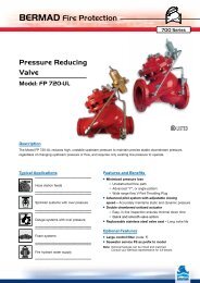
BERMAD Fire Protection<br />
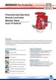
Electric<br />
Pressure Control<br />
Deluge Valve<br />
with EasyLock Manual Reset<br />
Model: <strong>FP</strong> <strong>400E</strong>-<strong>2MC</strong><br />
Typical Applications Features and Benefits<br />
Fluctuating or over pressure<br />
Petrochemical facilities<br />
Tunnels<br />
Power plants & transformers<br />
Flammable materials storage<br />
Aviation & airports<br />
400 Series<br />
■ Pressure control function –<br />
Constant preset downstream pressure<br />
■ Latch open – Closes upon local reset only<br />
■ One-piece molded elastomeric moving part –<br />
No maintenance required<br />
■ Obstacle-free full bore – Uncompromising reliability<br />
■ Factory pre-assembled trim – Out-of-box quality<br />
■ In-line serviceable – Minimal down time<br />
Optional Features<br />
■ Water motor alarm<br />
■ Alarm pressure-switch (code: P or P7)<br />
■ Explosion-proof for hazardous locations (code: 7/8/9)<br />
■ Hydraulic release (requires trim extension)<br />
■ Valve Position Single/Double Limit Switches
BERMAD Fire Protection<br />
Model: <strong>FP</strong> <strong>400E</strong>-<strong>2MC</strong><br />
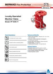
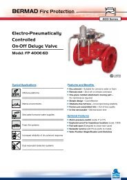
Operation<br />
400 Series<br />
The BERMAD Model <strong>FP</strong> <strong>400E</strong>-<strong>2MC</strong> is suitable for systems that include electric fire detection and a piping system with<br />
a wide variety of open nozzles. Combining a pressure control feature, the model <strong>FP</strong> <strong>400E</strong>-<strong>2MC</strong> is recommended for<br />
systems with high pressure supply source and/or with relatively low flow.<br />
In the SET position, the line-pressure supplied to both the main valve’s control chamber [1] and to a Hydraulic Relay<br />
Valve (HRV) [2] via the priming line [3], and through a Check Valve [4], an Accelerator [5] with priming restriction, and<br />
an EasyLock Manual Reset [6] is trapped by the Check Valve, by the closed HRV, by a Solenoid Valve [7], and by a<br />
closed Manual Emergency Release [8]. The trapped pressure holds the main valve’s diaphragm and plug against the<br />
valve seat [9], sealing it drip-tight and keeping the system piping dry.<br />
Under FIRE condition, an electric signal triggers the Solenoid Valve to open, opening the HRV. Pressure is then<br />
released from the main valve’s control chamber to the downstream, the open HRV and the Pressure Reducing (PR)<br />
Pilot valve [10]. The EasyLock prevents line-pressure from entering the HRV, allowing the main valve to latch open, and<br />
water to flow into the system piping and to the alarm device [11]. Should system pressure rise above PR pilot setting,<br />
the PR pilot throttles, thereby enabling pressure to accumulate in the valve control chamber. This causes the <strong>400E</strong>-<br />
<strong>2MC</strong> to throttle closed, decreasing system pressure to PR pilot setting. The Manual Emergency Release [8], overrides<br />
the PR pilot, causing the <strong>FP</strong> <strong>400E</strong>-<strong>2MC</strong> to open fully.<br />
C<br />
[7]<br />
[6]<br />
[5]<br />
Engineer Specifications<br />
■ The deluge valve shall be a UL-Listed, electrically controlled elastomeric type globe valve with a rolling-diaphragm.<br />
■ The valve shall have an unobstructed flow path, with no stem guide or supporting ribs.<br />
■ Valve actuation shall be accomplished by a fully peripherally supported, one-piece balanced rolling-diaphragm,<br />
vulcanized with a rugged radial seal disk. The diaphragm assembly shall be the only moving part.<br />
■ The valve shall have a removable cover for quick in-line service enabling all necessary inspection and servicing.<br />
■ The control trim materials shall consist of St.St. 316 tubing and fittings, and plated brass accessories, including local<br />
EasyLock Manual Reset, 2-way Solenoid Pilot Valve, Y strainer and Manual Emergency Release.<br />
■ The control trim shall be supplied as an assembly, pre-assembled and hydraulically tested at an ISO 9000 and 9001<br />
certified factory.<br />
[8]<br />
[4]<br />
[2]<br />
[1]<br />
[3]<br />
Valve Closed (set position) Valve Open (operating condition)<br />
■ The Pressure Control and Electrically Controlled Deluge Valve shall latch open in response to activation of the<br />
solenoid, reducing higher upstream pressure to lower preset downstream pressure. The valve shall reset to the<br />
closed position only upon local manual activation of the reset device.<br />
[9]<br />
C<br />
E<br />
[8]<br />
[10]<br />
[11]
BERMAD Fire Protection<br />
Model: <strong>FP</strong> <strong>400E</strong>-<strong>2MC</strong><br />
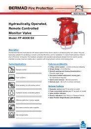
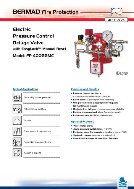
System Components<br />
1 - Main Valve, BERMAD <strong>FP</strong> <strong>400E</strong> Series<br />
2A - Gauge Valve<br />
2B - Accelerator with Priming Restriction<br />
2R - Pressure Reducing Pilot<br />
3A - Pressure Gauge (3 units)<br />
4B - Priming Strainer<br />
5A - Drain Valve<br />
7B - Check Valve<br />
11A - Alarm Shutoff Valve<br />
14A - Check Valve<br />
14B - Solenoid Valve<br />
15B - Manual Emergency Release<br />
18B - Priming Ball Valve<br />
19B - Drip Check<br />
26B - Hydraulic Relay Valve (HRV)<br />
M - EasyLock Manual Reset<br />
Optional<br />
P - Pressure Switch<br />
W - Water Motor Assembly<br />
S - Valve Position<br />
Limit Switch / Switches<br />
14A<br />
14B<br />
M<br />
7B<br />
4B<br />
26B<br />
2B<br />
18B<br />
P<br />
11A<br />
UL Listed<br />
The BERMAD Model <strong>FP</strong> <strong>400E</strong>-<strong>2MC</strong> is<br />
UL-Listed when installed<br />
with specific components and accessories.<br />
1<br />
19B<br />
3A<br />
5A<br />
2A<br />
2R<br />
15B<br />
400 Series<br />
Hydraulic<br />
Electric<br />
Atmosphere
BERMAD Fire Protection<br />
Model: <strong>FP</strong> <strong>400E</strong>-<strong>2MC</strong><br />
Technical Data<br />
Dimensions<br />
Size<br />
Th Tb<br />
Dv<br />
TI<br />
Ts Tw<br />
400 Series<br />
1½”, 2” 2½” 3” 4” 6” 8” 10” 12”<br />
mm inch mm inch mm inch mm inch mm inch mm inch mm inch mm inch<br />
(1) L1 205 81 /16 205 81 /16 257 101 /8 320 125 /8 415 165 /16 500 1911 /16 605 2313 /16 725 289 /16<br />
(2) L4 205 81 /16 N/A N/A 250 913 /16 320 125 /8 415 165 /16 500 1911 /16 N/A N/A N/A N/A<br />
TI 142 55 /8 142 55 /8 119 411 /16 84 35 /16 57 21 /4 - - - - - -<br />
Tw 228 9 220 8 11 /16 243 9 9 /16 253 10 312 12 5 /16 326 12 13 /16 346 13 5 /8 391 15 3 /8<br />
Ts 228 9 220 8 11 /16 243 9 9 /16 253 10 318 12 1 /2 326 12 13 /16 326 12 13 /16 391 15 3 /8<br />
Th 226 8 7 /8 242 9½ 262 10 5 /16 261 10 5 /16 356 14 407 16 407 16 546 21 1 /2<br />
Tb 278 10 1 /16 289 11 3 /8 300 11 13 /16 337 13 1 /4 378 14 7 /8 405 15 15 /16 413 16 1 /4 473 18 5 /8<br />
Dv Ø ¾” 1½” 1½” 2” 2” 2” 2” 2”<br />
Notes:<br />
1. L 1 is for flanged ANSI #150 and ISO PN16.<br />
2. L 4 is for grooved end connections (Ductile Iron Only).<br />
3. Provide adequate space around valve for maintenance.<br />
4. Data is for envelope dimensions, specific component<br />
positioning may vary.<br />
Connection Standard<br />
• Flanged: ANSI B16.42 (Ductile Iron),<br />
B16.5 (Steel & Stainless Steel),<br />
B16.24 (Bronze) or ISO PN16<br />
• Grooved: ANSI/AWWA C606 for 2, 3, 4, 6 & 8”<br />
Water Temperature<br />
• 0.5 – 50°C (33 – 122°F)<br />
Available Sizes<br />
• 1½, 2, 2½, 3, 4, 6, 8, 10 & 12"<br />
• UL-Listed for sizes 1½, 2, 2½, 3, 4, 6, 8 & 10”<br />
Pressure Rating*<br />
• Max. inlet: 250 psi (17 bar)<br />
• Set: 30-165 psi (4.5-11.5 bar)<br />
* Pressure rating might be limited due to solenoid valve rating<br />
Manufacturers Standard Materials<br />
Main valve body and cover<br />
•Ductile Iron ASTM A-536<br />
Main valve internals<br />
•Stainless Steel 304 & Cast Iron<br />
Control Trim System<br />
•Brass control components/accessories<br />
•Forged Brass pressure reducing pilot<br />
with St. St. 304 internals & NBR<br />
elastomers<br />
•Stainless Steel 316 tubing & fittings<br />
Elastomers<br />
•Nylon fabric reinforced polyisoprene NR<br />
Coating<br />
•Electrostatic Powder Coating Polyester,<br />
Red (RAL 3002)<br />
Set<br />
Va lue<br />
Optional Materials<br />
Main valve body<br />
• Carbon Steel ASTM A-216 WCB<br />
• Stainless Steel 316<br />
• Ni-Al-Bronze ASTM B-148<br />
Control Trim<br />
• Stainless Steel 316<br />
• Monel® and Ni-Al-Bronze<br />
• Hastalloy C-276<br />
Elastomers<br />
• NBR<br />
• EPDM<br />
Coating<br />
• High Build Epoxy Fusion-Bonded<br />
with UV Protection, Anti-Corrosion<br />
bermadfire@bermad.com • www.bermad.com<br />
The information herein is subject to change without notice. BERMAD shall not be held<br />
liable for any errors. All rights reserved. © Copyright by BERMAD. PE4PE-<strong>2MC</strong> 11<br />
psi<br />
Set Va lue<br />
-2.0<br />
-4.0<br />
-6.0<br />
-8.0<br />
-10.0<br />
-12.0<br />
-14.0<br />
-16.0<br />
-18.0<br />
-20.0<br />
m 3 /h<br />
Valve Outlet Pressure Fall-off Characteristics<br />
On Inlet Under Set Pressure<br />
21 1 /2”<br />
1 /2, 2” 3” 4” 6” 8” 10”<br />
gpm<br />
20<br />
30<br />
90<br />
120<br />
50<br />
200<br />
70<br />
300<br />
600<br />
150<br />
200<br />
300<br />
500<br />
700<br />
800<br />
1200<br />
2000<br />
3000<br />
800<br />
900<br />
1200<br />
4000<br />
5000<br />
-0.0<br />
-0.3<br />
-0.4<br />
-0.7<br />
-1.0<br />
-1.2<br />
-1.4<br />
L 1<br />
L 4<br />
Solenoid Pilot Valves<br />
Standard<br />
• 2-way Pilot Operated type<br />
• Brass body<br />
• Main valve closed when de-energized<br />
• Enclosure: General purpose watertight,<br />
NEMA 4 and 4X / IP65, Class F<br />
• Power: 24VDC, 8 watts<br />
• UL - Listed<br />
Options (see also ordering guide)<br />
• Hazardous locations:<br />
• Class l Division 1, Gr. A, B, C, D, T4 (code 7)<br />
• ATEX, EEx em llC T4 (code 8)<br />
• ATEX, EEx d llC T4/5 (code 9)<br />
• Voltage: see ordering guide (voltage option table)<br />
• Stainless steel 316 body material (code K)<br />
12”<br />
bar