
You also want an ePaper? Increase the reach of your titles
YUMPU automatically turns print PDFs into web optimized ePapers that Google loves.
ICHCA International <strong>Safe</strong>ty Panel Briefing Pamphlet No 30<br />
5.4.3 Fusible Links<br />
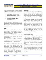
5.4.3.1 On closer examination Picture 35 shows<br />
two cables attached to the foot valve<br />
remote operating mechanism. The<br />
second cable is attached to a fusible<br />
link; these are usually fitted directly<br />
behind the bottom discharge valve<br />
assembly.<br />
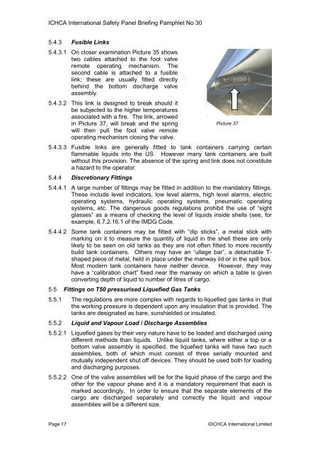
5.4.3.2 This link is designed to break should it<br />
be subjected to the higher temperatures<br />
associated with a fire. The link, arrowed<br />
in Picture 37, will break and the spring<br />
will then pull the foot valve remote<br />
operating mechanism closing the valve.<br />
5.4.3.3 Fusible links are generally fitted to tank containers carrying certain<br />
flammable liquids into the US. However many tank containers are built<br />
without this provision. The absence <strong>of</strong> the spring and link does not constitute<br />
a hazard to the operator.<br />
5.4.4 Discretionary Fittings<br />
5.4.4.1 A large number <strong>of</strong> fittings may be fitted in addition to the mandatory fittings.<br />
These include level indicators, low level alarms, high level alarms, electric<br />
operating systems, hydraulic operating systems, pneumatic operating<br />
systems, etc. The dangerous goods regulations prohibit the use <strong>of</strong> “sight<br />
glasses” as a means <strong>of</strong> checking the level <strong>of</strong> liquids inside shells (see, for<br />
example, 6.7.2.16.1 <strong>of</strong> the IMDG Code.<br />
5.4.4.2 Some tank containers may be fitted with “dip sticks”, a metal stick with<br />
marking on it to measure the quantity <strong>of</strong> liquid in the shell these are only<br />
likely to be seen on old tanks as they are not <strong>of</strong>ten fitted to more recently<br />
build tank containers. Others may have an “ullage bar”, a detachable Tshaped<br />
piece <strong>of</strong> metal, held in place under the manway lid or in the spill box.<br />
Most modern tank containers have neither device. However, they may<br />
have a “calibration chart” fixed near the manway on which a table is given<br />
converting depth <strong>of</strong> liquid to number <strong>of</strong> litres <strong>of</strong> cargo.<br />
5.5 Fittings on T50 pressurised Liquefied Gas <strong>Tank</strong>s<br />
5.5.1 The regulations are more complex with regards to liquefied gas tanks in that<br />
the working pressure is dependent upon any insulation that is provided. The<br />
tanks are designated as bare, sunshielded or insulated.<br />
5.5.2 Liquid and Vapour Load / Discharge Assemblies<br />
Picture 37<br />
5.5.2.1 Liquefied gases by their very nature have to be loaded and discharged using<br />
different methods than liquids. Unlike liquid tanks, where either a top or a<br />
bottom valve assembly is specified, the liquefied tanks will have two such<br />
assemblies, both <strong>of</strong> which must consist <strong>of</strong> three serially mounted and<br />
mutually independent shut <strong>of</strong>f devices. They should be used both for loading<br />
and discharging purposes.<br />
5.5.2.2 One <strong>of</strong> the valve assemblies will be for the liquid phase <strong>of</strong> the cargo and the<br />
other for the vapour phase and it is a mandatory requirement that each is<br />
marked accordingly. In order to ensure that the separate elements <strong>of</strong> the<br />
cargo are discharged separately and correctly the liquid and vapour<br />
assemblies will be a different size.<br />
Page 17 ©ICHCA International Limited