TurboCAD Deluxe V16.2 Timber Frame Barn ... - Textual Creations
TurboCAD Deluxe V16.2 Timber Frame Barn ... - Textual Creations
TurboCAD Deluxe V16.2 Timber Frame Barn ... - Textual Creations

Create successful ePaper yourself
Turn your PDF publications into a flip-book with our unique Google optimized e-Paper software.
Donald B. Cheke<br />
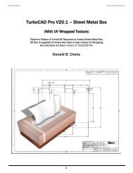
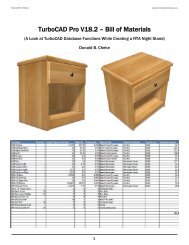
<strong>TurboCAD</strong> <strong>Deluxe</strong> <strong>V16.2</strong> – <strong>Timber</strong> <strong>Frame</strong> <strong>Barn</strong><br />
- The Hermes -<br />
Donald B. Cheke<br />
1<br />
www.textualcreations.ca
Donald B. Cheke<br />
Copyright © 2010 Donald B. Cheke<br />
All rights reserved<br />
No part of this document may be reproduced, copied, stored on a retrieval system or transmitted in any<br />
form without written permission from the author. The purchaser may, however, pri print one copy of the<br />
document to paper and may make one backup copy of the downloaded material for personal safe<br />
keeping.<br />
Limitation of Liability<br />
While every effort has been taken in the preparation and the writing of this document the author<br />
assumes no responsibility sponsibility for errors and/or omissions nor for the uses of the material and the decisions<br />
based on such use. No warranties are made, express or implied with regard to either the contents of the<br />
document, its merchant ability or fitness for a particular ppurpose.<br />
urpose. The author should not be liable for<br />
direct, indirect, special, incidental or consequential damages arising out of the use or inability to use the<br />
contents of this document.<br />
Special Note<br />
<strong>TurboCAD</strong> is a registered trademark of IMSI/Design.<br />
All of the work presented within this tutor tutorial is based on <strong>TurboCAD</strong> <strong>Deluxe</strong> V16 <strong>V16.2</strong>. Although users of<br />
previous versions are welcome to try the tutorial it cannot be stated what results will be achieved. Many<br />
changes, some subtle and others not so subtle, are made with each program revision. Although many<br />
steps and directions rections would be generic some may not be. The same can be said for tools between<br />
versions. Older versions may not have the same tools as <strong>Deluxe</strong> <strong>V16.2</strong> and if the same tools are available<br />
the tools themselves may have been revised and hence, work in a diffe different rent manner than they previously<br />
did.<br />
2<br />
www.textualcreations.ca<br />
Published by:<br />
Donald B. Cheke<br />
Saskatoon, SK Canada<br />
Visit: www.textualcreations.ca
Donald B. Cheke www.textualcreations.ca<br />
Table of Contents<br />
Table of Contents ......................................................................................................................................................... 3<br />
Introduction .................................................................................................................................................................. 4<br />
Setup .............................................................................................................................................................................. 6<br />
Initial Lighting ............................................................................................................................................................. 13<br />
The Hermes <strong>Barn</strong> – Main <strong>Timber</strong>s .......................................................................................................................... 18<br />
Hammer Beam Bent ................................................................................................................................................. 20<br />
Image Insertion and Scale ....................................................................................................................................... 43<br />
Hammer Beam Bent – Continued ........................................................................................................................... 46<br />
Upper Roof Rafters .................................................................................................................................................... 60<br />
Stall Area <strong>Timber</strong>s ..................................................................................................................................................... 78<br />
Wall Panels – SIP – Session 1................................................................................................................................. 99<br />
Doors ......................................................................................................................................................................... 118<br />
Wall Panels – SIP – Session 2.............................................................................................................................. 122<br />
Roof Panels – SIP ................................................................................................................................................... 124<br />
Soffits and Fascia ................................................................................................................................................... 128<br />
Shingles .................................................................................................................................................................... 139<br />
Windows ................................................................................................................................................................... 147<br />
Concrete Slab .......................................................................................................................................................... 159<br />
Bent – Exploded View ............................................................................................................................................. 161<br />
SIP Panel – Exploded View .................................................................................................................................... 187<br />
Ground Plane ........................................................................................................................................................... 201<br />
Named Views ........................................................................................................................................................... 202<br />
Signage ..................................................................................................................................................................... 210<br />
Materials Application ............................................................................................................................................. 215<br />
Render Scene Luminance ..................................................................................................................................... 238<br />
Render Scene Environment .................................................................................................................................. 242<br />
Saving the Rendered Image.................................................................................................................................. 246<br />
Paper Space – Title Block ..................................................................................................................................... 249<br />
Paper Space – Pages with Viewports & Annotations ....................................................................................... 273<br />
Printing ..................................................................................................................................................................... 311<br />
Appendix .................................................................................................................................................................. 313<br />
3
Donald B. Cheke www.textualcreations.ca<br />
Introduction<br />
A large user focus of any CAD software is ultimately the architectural / construction field. Whether a user<br />
is designing a cabin, a house, or other unnamed structure a user must feel that they can depend fully on<br />
the CAD software that they purchased – that it will meet their needs in a timely and hassle free manner.<br />
It is the author's belief that <strong>TurboCAD</strong> can and will meet the needs of most builders without too much<br />
trouble, once over the initial learning curve that is part of any software package.<br />
Within this very comprehensive tutorial the reader will be led through each keystroke to produce all<br />
components of the timber frame barn that is illustrated on the cover of the tutorial. The reader will learn<br />
how to create each object by manipulating 2D profiles and 3D primitive shapes. The reader will learn<br />
how to set up their drawing, how to insert standard lighting and how utilize render scene luminance. The<br />
reader will learn how to establish a render scene environment and the reader will learn how to render<br />
their drawing and save it in a high resolution image format. Additionally the reader will be led through<br />
the steps to create a title block and a six page paper space presentation.<br />
This tutorial is in no way intended to teach timber framing, but rather, it is intended to teach the use of<br />
some of the tools that <strong>TurboCAD</strong> has to offer and to introduce the new user to a drawing methodology.<br />
The author feels confident that the techniques outlined within the tutorial can help lay the foundation for<br />
future successful <strong>TurboCAD</strong> drawing and illustration for even the newest user.<br />
As with any technically advanced software, the user is generally faced with a steep learning curve. It is<br />
the hope of the author that the money and time spent working through a <strong>Textual</strong> <strong>Creations</strong> tutorial will<br />
help ease the learning and allow the reader to come away feeling confident that they made a wise<br />
decision.<br />
This tutorial will assume that the reader has <strong>TurboCAD</strong> <strong>Deluxe</strong> <strong>V16.2</strong>.<br />
There are many ways to approach a project and it is likely that each person using the program would<br />
proceed in very different ways, so be open to alternative methods as experience builds. What is<br />
important is that the user becomes familiar with the objects that they wish to model and begin to look at<br />
them in a different way than they might otherwise do. What primitive shapes make up the whole? What<br />
will be required of these primitive shapes early in the drawing and how will this affect needs further<br />
along? What component or components should be started with? Many questions can only be answered<br />
through experience, but hopefully some of them will be answered by the time the beginner has worked<br />
through this tutorial. There is a great deal covered in this tutorial and the author urges the beginner to be<br />
patient, to read very carefully and to take the time necessary to do a good job. Try to enjoy the process as<br />
much as you will enjoy the final results.<br />
This tutorial assumes that the beginner has studied the desktop to some degree and can locate most of<br />
the tools. Since there are endless desktop configurations that can be set up in <strong>TurboCAD</strong> the author has<br />
opted to illustrate the required tools with the V16 user interface, and the default toolbars in their<br />
undocked format (Office 2000 theme).<br />
4
Donald B. Cheke www.textualcreations.ca<br />
The beginner should not overlook the importance of the internet as a resource for material to help<br />
understand the dynamics of what they are trying to model. If only to help gain a better understanding of<br />
what a user is modeling a Google image search and regular web search is time well spent. Doing just so,<br />
with the intent of creating this tutorial, the author happened across Vermont <strong>Timber</strong> Works<br />
(http://www.vermonttimberworks.com/), a Vermont based business that builds timber frame structures.<br />
Being quite taken by the quality of the workmanship presented on their website and material available<br />
there, in particular the Hermes <strong>Barn</strong>, the author contacted Vermont <strong>Timber</strong> Works and asked for<br />
permission to use the Hermes barn material on their web site as a basis for this tutorial. The vice<br />
president of the company responded in the positive and wished us well on the new tutorial project. So it<br />
is with great pleasure that '<strong>TurboCAD</strong> <strong>V16.2</strong> <strong>Deluxe</strong> – <strong>Timber</strong> <strong>Frame</strong> <strong>Barn</strong>' is presented. Please check out<br />
the Hermes <strong>Barn</strong> and note that there are some PDF files on the website that illustrate what will be<br />
worked toward within the tutorial. Since this is a tutorial, the author reserves the right to make<br />
adjustments as deemed necessary to ensure the tutorial does not become too burdened with detail and<br />
become excessively long. http://www.vermonttimberworks.com/home/projects/hermes/index.html<br />
The author has borrowed the timber frame definitions from:<br />
http://www.timberframedesign.net/timberglossary.html and<br />
WordWeb 4.5A Free Version (http://wordweb.info/).<br />
Please remember that any supplied images and files are for use within the tutorial only and may not be<br />
shared or sold to others.<br />
Place tutorial images in a permanent location on the hard drive.<br />
A couple fonts are used in the tutorial and they have been supplied. They may already be part of those<br />
supplied with Windows. If required, they should be installed in the Windows Font folder while <strong>TurboCAD</strong><br />
is closed, so they will load when <strong>TurboCAD</strong> is started.<br />
5
Donald B. Cheke www.textualcreations.ca<br />
Type 2D in the Layer name field and click OK or press Enter.<br />
Turn off the new layer by left mouse clicking the eyes icons that correspond to the new layer. Please note<br />
that layer 0 should remain visible at all times as the program uses this layer for internal processes.<br />
Select the red profile and then assign it to the 2D layer by left mouse clicking the clear box to the right of<br />
the 2D layer name on the Design Director palette. A green arrow will appear indicating that the<br />
procedure was done and the selection will disappear as the layer is not visible.<br />
Alternately objects can be assigned to their layers via the Properties toolbar at the top of the <strong>TurboCAD</strong><br />
desktop.<br />
The author finds that saving most of the 2D profiles is a good habit to get into. Should a user need to<br />
recreate some 3D object due to problems that are encountered then there is less work involved as the<br />
profiles are still intact.<br />
Not all the timbers are 8 × 8; some are supposed to be 6 × 8 and those that are supposed to be 6 × 8<br />
will now be changed. According to the plan, the 6 × 8 timbers and the knee braces are flush with the face<br />
of the first and fourth bent and centered on the second and third bent.<br />
Select the four timbers as indicated in the picture below.<br />
41
Donald B. Cheke www.textualcreations.ca<br />
Tab into the Inspector Bar and enter 6 in the Size Y field. Press Enter.<br />
Tab into the Inspector Bar once more and enter -1 in the Delta Y field. Press Enter to move the selection<br />
forward.<br />
Select the three knee braces. Tab into the Inspector Bar and enter -3 in the Delta Y field. Press Enter to<br />
move the selection forward.<br />
Press Esc to deselect the selection.<br />
42
Donald B. Cheke www.textualcreations.ca<br />
With the rafter block still selected, select the Linear Copy tool from the Copy toolbar.<br />
Tab into the Inspector Bar and enter 0 in the X Step field, 3' 7 3/16 in the Y Step field, 0 in the Z Step<br />
field and 4 in the Sets field. Press Enter.<br />
Select the remainder of the exploded bent, not the rafters, and then Tab into the Inspector Bar and enter<br />
-50' in the Delta X field. Press Enter to move it out of the way.<br />
Turn on the four Bent layers.<br />
Select the four rafter blocks. Press D SEKE and relocate (M SEKE) the reference point to the middle of the<br />
bottom line of the right post on bent 1, as indicated in the picture below.<br />
63
Donald B. Cheke www.textualcreations.ca<br />
Right mouse click and select Rubber Stamp from the Local Menu. M SEKE snap at the corresponding<br />
mid-points on bent 2 and bent 3 to place two copies, as indicated in the picture below. Zoom in close to<br />
ensure that the correct location is snapped to. Zoomed out image below.<br />
Press Esc to exit the Rubber Stamp tool.<br />
The ridge will now be placed.<br />
Select the girt at the moved bent components.<br />
Select the Make Copy tool to turn it on.<br />
Tab into the Inspector Bar and enter 90 in the Z Rotation field. Press Enter.<br />
Select the Make Copy tool to turn it off.<br />
Press D SEKE and relocate (M SEKE) the reference point to the top forward line of the rotated girt.<br />
64
Donald B. Cheke www.textualcreations.ca<br />
Create a new layer caller Knee Braces.<br />
Select all of the knee braces and assign them to the Knee Brace layer. Do not deselect.<br />
Turn on the Bent 1 layer.<br />
Switch to Front view.<br />
Select Plane by Active View from the Workplane toolbar.<br />
Select the Mirror Copy tool from the Copy toolbar.<br />
M SEKE snap the bottom side of the girt to define the first point of the mirroring line. Press and hold the<br />
Shift key down. Move the cursor downward a short distance and then left mouse click to define the<br />
second point of the mirroring line. Release the Shift key. In progress below.<br />
Press Esc to deselect the selection.<br />
It is time for a render check.<br />
Turn on all the layers except the 2D and Image layer.<br />
Switch to Isometric SE view.<br />
Press Ctrl + A to select all the components in the drawing.<br />
97
Donald B. Cheke www.textualcreations.ca<br />
Press and hold the Shift key down. Drag a selection box around the components of the exploded bent to<br />
deselect them. Release the Shift key. In progress below.<br />
Right mouse click on the Suppress Hidden Line rendering tool on the Render toolbar to open the Camera<br />
Properties. Check Hidden Line and uncheck Nonrenderable objects. Nothing else is checked. Click OK.<br />
Press Esc after the render occurs and then select Zoom Extents at the top of the <strong>TurboCAD</strong> desktop and<br />
turn off the grid.<br />
98
Donald B. Cheke www.textualcreations.ca<br />
Turn off all the layers except the Left and Right Walls layers and layer 0.<br />
The selected red rectangle outlines the area where the windows will be contained within.<br />
With the rectangle still selected, select the Make Copy tool to turn it on.<br />
Tab into the Inspector Bar and enter 5' in the Size X field and 3' in the Size Y field. Press Enter.<br />
Select the Make Copy tool to turn it off.<br />
Turn on the four Bent layers.<br />
To help determine where the other two windows will be located select the Line tool from the Line toolbar.<br />
Using two V SEKE snaps per line place two lines - one between two inner vertexes between bent three<br />
and four and one between two inner vertexes between bent one and two as indicated in the picture<br />
below.<br />
Press the Space Bar to exit the tool.<br />
Turn off the four Bent layers.<br />
Select the left line that was just created.<br />
149
Donald B. Cheke www.textualcreations.ca<br />
Copy the number in the Y Position field. Press Esc to move out of the Inspector Bar.<br />
Select the Make Copy tool to turn it on.<br />
Select the smaller central rectangle and then Tab into the Inspector Bar and paste the copied number<br />
into the Position Y field. Press Enter.<br />
Select the right line that was previously created.<br />
Copy the number in the Y Position field. Press Esc to move out of the Inspector Bar.<br />
Select the smaller central rectangle and then Tab into the Inspector Bar and paste the copied number<br />
into the Position Y field. Press Enter.<br />
Select the Make Copy tool to turn it off.<br />
Press Esc to deselect the selection.<br />
150
Donald B. Cheke www.textualcreations.ca<br />
Ensure the Two sided extrude option is engaged.<br />
Extrude each red rectangle, one at a time, by selecting it, entering 1 in the Height field and pressing<br />
Enter.<br />
That creates 2" thick objects.<br />
Press the Space Bar to exit the tool when complete.<br />
Press Ctrl + K to open the Select by Colors dialogue. Select Blue and click OK.<br />
Assign the selection to the 2D layer.<br />
Select the six boxes at the knee braces.<br />
Tab into the Inspector Bar and enter -3 in the Delta Y field. Press Enter to move them in line with the<br />
knee braces. Do not deselect.<br />
Select Explode one time from the Format menu at the top of the <strong>TurboCAD</strong> desktop so that they can be<br />
resized.<br />
Tab into the Inspector Bar and enter 1.5 in the Size Z field. Press Enter.<br />
Zoom in on the joint where the lower rafter and the post of the left stall area meet.<br />
Select the 3D Subtract tool from the Boolean & Facet toolbar.<br />
Select the Don't remove the subtrahend option.<br />
171
Donald B. Cheke www.textualcreations.ca<br />
Tab into the Inspector Bar and enter -18 in the Delta Z field. Press Enter.<br />
Press Esc to deselect the selection.<br />
The positioning could be made to look a bit better.<br />
Select the objects as indicated in the picture below.<br />
Tab into the Inspector Bar and enter 18 in the Delta Z. Press Enter.<br />
Press Esc to deselect the selection.<br />
186
Donald B. Cheke www.textualcreations.ca<br />
SIP Panel – Exploded View<br />
During the author's tenure in the world of construction SIP panels (Structural Insulated Panels) were not<br />
a common part of the industry. After a quick review of these products it seems that there are basically<br />
two types, one with only a polystyrene interior and the other with a dimensional lumber and polystyrene<br />
interior. It is the understanding of the author that the panels that contain the dimensional lumber would<br />
be used to construct a structure that does not have a supporting frame. Since the timber frame barn<br />
does have a supporting frame it seems logical that the non-inner structural panels could be used.<br />
At this time an exploded wall panel will be created to illustrate what would be used on the walls and roof<br />
of the barn. It will also be inserted into paper space later in the tutorial.<br />
Switch to Isometric SE view.<br />
Select Plane by World from the Workplane toolbar.<br />
Select the Box tool from the 3D Object toolbar.<br />
In a clear area of the drawing G SEKE snap to place the first point of the box. Tab into the Inspector Bar<br />
and enter 4' in the Width field, 8' in the Length field and -.5 in the Height field. Press Enter.<br />
Press the Space Bar to exit the tool.<br />
Select the panel. Tab into the Inspector Bar and enter 90 in the X Rotation field. Press Enter.<br />
Right mouse click and select Rubber Stamp from the Local Menu. Move the cursor to the right and left<br />
mouse click to place a copy nearby. In progress below.<br />
187
Donald B. Cheke www.textualcreations.ca<br />
Turn off the Ground Plane layer.<br />
Turn the layers on or off, as indicated in the picture below.<br />
Named Views<br />
Before a view can be named the drawing must be maneuvered into a desirable view. This is done with<br />
the Walk Through tools but before this is done the camera perspective will be engaged.<br />
Right mouse click the Wireframe render icon on the Render toolbar to open the Camera Properties.<br />
Under the Camera tab check Perspective View and slide the View Angle to 53.858. Click OK.<br />
Switch to Front view.<br />
Select the Examine tool from the Walkthrough toolbar.<br />
Select Look To Drawing Center from the View / Camera menu at the top of the <strong>TurboCAD</strong> desktop.<br />
202
Donald B. Cheke www.textualcreations.ca<br />
Use the Walk tool again, if needed, to move further in.<br />
Press Esc to turn off the Walk Through tool.<br />
Right mouse click on one of the Standard View icons to open the Named View dialogue. Enter Inside<br />
Front Doors in the Name field. Click New. Click Close.<br />
Select the Wireframe tool twice, once to end the render and once to turn off perspective.<br />
Turn off all layers, except layer 0 and Front wall.<br />
Signage<br />
Switch to Front view.<br />
Select Plane by Active View from the Workplane toolbar.<br />
Select the Text tool from the Text toolbar.<br />
210
Donald B. Cheke www.textualcreations.ca<br />
Click OK to exit the Render Scene Environment Editor and click OK to exit the Drawing Setup dialogue.<br />
Allow the scene to rerender (26 seconds on the author's off the shelf HP).<br />
Saving the Rendered Image<br />
This render will now be saved.<br />
The author has found that saving as a high resolution BMP or JPG produces excellent results. If a smaller<br />
image is required afterward, resizing with an image editor and saving in JPG format retains the excellent<br />
results. With the desired view now fully rendered on screen select Save As from the File menu at the top<br />
of the <strong>TurboCAD</strong> desktop.<br />
Under the Save As dialogue, select the desired Save in location from the dropdown menu at the top of<br />
the dialogue.<br />
Select JPG – <strong>TurboCAD</strong> for Windows JPEG from the Save as type dropdown menu.<br />
Enter the file name <strong>Timber</strong> <strong>Frame</strong> <strong>Barn</strong> Tutorial v16.jpg. Select Setup.<br />
Adjust the setting to match those in the image below. Click OK.<br />
246
Donald B. Cheke www.textualcreations.ca<br />
Select 12 pt from the Font Size dropdown menu on the Property toolbar.<br />
Press Esc to deselect the selection.<br />
Select Zoom Full View.<br />
Paper Space – Pages with Viewports & Annotations<br />
There is eventually going to going to be six paper space pages. For the most part, views will be added to<br />
each page first and then each page will be adjusted and annotated to suit.<br />
Double click 1 OF 1 at the lower left corner of the sheet to open the Properties dialogue. Under the<br />
General tab, change the text to read 1 of 6. Click OK.<br />
Select the Insert Viewport tool from the Named View toolbar.<br />
273
Donald B. Cheke www.textualcreations.ca<br />
G SEKE snap the first point of the viewport at the grid location indicated in the picture below.<br />
G SEKE snap the second point of the viewport at the grid location indicated in the picture below.<br />
Viewport (and images) are always<br />
placed upper left corner to lower<br />
right corner.<br />
The Named view dialogue opens. Select Front and click Go to. Click Close.<br />
Right mouse click on the Paper 1 tab at the bottom of the screen and select Duplicate.<br />
274
Donald B. Cheke www.textualcreations.ca<br />
From the Tools menu at the top of the <strong>TurboCAD</strong> desktop select Architecture / Markers / Circle mark.<br />
With the tool active, right mouse click and select Mark properties from the local menu. This can be done<br />
at any time during placement, should the reader need to change the Number field.<br />
Adjust the settings to reflect what is in the image below.<br />
298
Donald B. Cheke www.textualcreations.ca<br />
Click OK.<br />
Using left mouse clicks place the markers, as indicated in the picture below.<br />
Right mouse click and select Finish drawing mark from the local menu.<br />
299
Donald B. Cheke www.textualcreations.ca<br />
Select the Text tool from the Text toolbar.<br />
Open the Properties for the tool and adjust the settings to reflect what is in the image below. Click OK.<br />
Left mouse click in the area to the right of the #1 marker and type the following (be sure to press Shift +<br />
Enter to move to the next line when necessary). Select Finish when complete.<br />
1. Stall Corner Post<br />
2. Stall Rafter<br />
3. Corner Post<br />
4. Brace<br />
5. Girt<br />
6. Lower Tie<br />
7. Hammer Post<br />
8. Upper Rafter<br />
9. Upper Tie<br />
10. King Post<br />
Press the Space Bar to exit the tool.<br />
300
Donald B. Cheke www.textualcreations.ca<br />
Select Zoom Full View.<br />
Right mouse click on the Paper 4 tab at the bottom of the screen and select Duplicate.<br />
Select the Paper 5 tab.<br />
Select and delete the viewports, annotation and the dimensions.<br />
Double click 4 OF 6 at the lower left corner of the sheet to open the Properties dialogue. Under the<br />
General tab, change the text to read 5 of 6. Click OK.<br />
Select the Insert Viewport tool from the Viewport toolbar.<br />
Using two G SEKE snaps place a viewport as indicated in the picture below. In progress below.<br />
301