Movorail - tollo linear ab, kristianstad, sweden
Movorail - tollo linear ab, kristianstad, sweden
Movorail - tollo linear ab, kristianstad, sweden

You also want an ePaper? Increase the reach of your titles
YUMPU automatically turns print PDFs into web optimized ePapers that Google loves.
<strong>Movorail</strong><br />
Installation Manual<br />
Edition: 4<br />
DW110410gb-0710
<strong>Movorail</strong> MARCH 2007 THOMSON<br />
Version History<br />
Edition Number Edition Date Reason for Revision<br />
1 n.a. manual created<br />
2 n.a. Changed content<br />
3 2005-02-18 Changed content and new style<br />
4 2007-03-09 Added instruction for adjustment of bogie trolleys<br />
DANAHER MOTION is a registered trademark of Danaher Corporation. Danaher Motion makes every attempt<br />
to ensure accuracy and reli<strong>ab</strong>ility of the specifications in this publication. Specifications are subject to<br />
change without notice. Danaher Motion provides this information "AS IS" and disclaims all warranties, express<br />
or implied, including, but not limited to, implied warranties of merchant<strong>ab</strong>ility and fitness for a particular<br />
purpose. It is the responsibility of the product user to determine the suit<strong>ab</strong>ility of this product for a specific<br />
application.<br />
2 DW110410gb-0710 Edition: 4 Installation Manual
<strong>Movorail</strong> MARCH 2007 THOMSON<br />
©2005 Danaher - Printed in Sweden. All rights reserved.<br />
T<strong>ab</strong>le of contents<br />
1. Introduction ...............................................................................................................................................5<br />
2. The components of the <strong>Movorail</strong> system ...............................................................................................6<br />
2.2 Single girder systems ................................................................................................................................... 7<br />
3. The <strong>Movorail</strong> rails .....................................................................................................................................8<br />
3.1 Rails.............................................................................................................................................................. 8<br />
3.2 Attachment of reinforcement profile type SPF 135 ....................................................................................... 8<br />
4. Connection of rails......................................................................................................................................9<br />
4.1 Connection of straight rails type SPR ........................................................................................................... 9<br />
4.2 Connection of curves type SPB .................................................................................................................... 9<br />
5. Service sections ........................................................................................................................................10<br />
5.1 Installation and inspection of service sections type SSKT .......................................................................... 10<br />
6. Trolleys and accessories for trolleys ...................................................................................................11<br />
6.1 Trolleys ....................................................................................................................................................... 11<br />
6.2 Installation of rail and trolley attachments type KFFB, KFKK, KFVS and KFSB ......................................... 12<br />
6.3 Adjustment of bogie trolleys type BGV 300 HSE with support rollers ......................................................... 13<br />
6.4 C<strong>ab</strong>le trolleys type KBV, KBVA and KBVS ................................................................................................. 14<br />
6.5 Pick up trolleys type STV5 and STVG5 ...................................................................................................... 15<br />
6.6 Installation of motor trolleys type TMT ........................................................................................................ 16<br />
6.7 Adjustment of centre of gravity on motor trolley type TMT.......................................................................... 16<br />
6.8 Electrical connection and adjustment of motor trolleys type TMT ............................................................... 17<br />
7. End plates, end stops, motion limiters and Walter bolts....................................................................18<br />
7.1 End stops type STP, end plates type TPL and end plate supports type EPF ............................................. 18<br />
7.2 Motion limiters type BGR ............................................................................................................................ 18<br />
7.3 Walter bolt type WBM ................................................................................................................................. 19<br />
8. Location of suspension..........................................................................................................................20<br />
8.1 Location of suspensions ............................................................................................................................. 20<br />
9. Suspensions............................................................................................................................................21<br />
9.1 General <strong>ab</strong>out suspensions ........................................................................................................................ 21<br />
9.2 Z-suspensions type DZ............................................................................................................................... 21<br />
9.3 I-beam clamps type VBKLA........................................................................................................................ 21<br />
9.4 Flexible suspensions type DBSU................................................................................................................ 22<br />
9.5 Adjust<strong>ab</strong>le suspensions type ASU .............................................................................................................. 22<br />
10. Safety c<strong>ab</strong>les for suspensions ..............................................................................................................23<br />
10.1 Safety c<strong>ab</strong>le type SLU ................................................................................................................................ 23<br />
11. Installation of current track ...................................................................................................................24<br />
11.1 General <strong>ab</strong>out current track ........................................................................................................................ 24<br />
11.2 Installation of current track type SB ............................................................................................................ 24<br />
11.3 Insertion of current track in to the <strong>Movorail</strong> profile ...................................................................................... 25<br />
11.4 Connection of current tracks with current track connection type ATSK 5.................................................... 25<br />
11.5 Electrical connection of current track with power supply track type ATSA 5 ............................................... 26<br />
12. Flexible bolt connection for trolleys and trolley safety c<strong>ab</strong>le ............................................................27<br />
12.1 Installation of flexible bolt connection for trolleys type BUB between trolley and crane rail......................... 27<br />
12.2 Installation of trolley safety c<strong>ab</strong>le type SLV................................................................................................. 27<br />
12.3 Installation of flexible bolt connection for trolleys type TBUB between trolley and crane rail ...................... 28<br />
13. Crane distance trolley and distance girders........................................................................................29<br />
13.1 Flexible distance girder type DNS............................................................................................................... 29<br />
13.2 Rigid distance girder type SD ..................................................................................................................... 29<br />
14. Switches and turnt<strong>ab</strong>les ........................................................................................................................30<br />
14.1 General <strong>ab</strong>out switches and turnt<strong>ab</strong>les....................................................................................................... 30<br />
14.2 Switches type HXL and VXL ....................................................................................................................... 30<br />
14.3 Turnt<strong>ab</strong>les type VSL ................................................................................................................................... 30<br />
15. C<strong>ab</strong>le loop................................................................................................................................................31<br />
15.1 Installation of c<strong>ab</strong>le loop ............................................................................................................................. 31<br />
>>> T<strong>ab</strong>le of content continues on the next page.>>><br />
Installation Manual DW110410gb-0710 Edition: 4 3
<strong>Movorail</strong> MARCH 2007 THOMSON<br />
T<strong>ab</strong>le of contents<br />
16. Testing the <strong>Movorail</strong> system..................................................................................................................32<br />
16.1 General <strong>ab</strong>out testing of the <strong>Movorail</strong> system............................................................................................. 32<br />
16.2 Inspection points at a test of a <strong>Movorail</strong> system ......................................................................................... 32<br />
17. Training and user instructions ..............................................................................................................33<br />
17.1 General <strong>ab</strong>out training ................................................................................................................................ 33<br />
17.2 User instructions ......................................................................................................................................... 33<br />
18. Technical data .........................................................................................................................................34<br />
18.1 Data for the <strong>Movorail</strong> profiles...................................................................................................................... 34<br />
18.2 Tightening torque for bolts .......................................................................................................................... 34<br />
18.3 Load diagram for a rail with a single load.................................................................................................... 35<br />
18.4 Technical data for current track type SB..................................................................................................... 35<br />
18.5 Voltage drop in c<strong>ab</strong>les ................................................................................................................................ 36<br />
4 DW110410gb-0710 Edition: 4 Installation Manual
<strong>Movorail</strong> MARCH 2007 THOMSON<br />
1. Introduction<br />
Thomson <strong>Movorail</strong> is a light weight rail system made of extruded aluminium profiles for loads up to 600 kg<br />
which is designed and manufactured by Danaher Motion to meet the latest national and international standards.<br />
Product quality is assured by our ISO 9001 certified quality system.<br />
Read trough this manual carefully and study all the instructions supplied with the delivery of the components<br />
before starting the installation work.<br />
Do not hesitate to contact us for more information.<br />
Important!<br />
• Read trough all installation instructions and all other diagrams and documents supplied with the delivery before commencing the<br />
installation in order to ensure that the work is carried out in a safe manner.<br />
• No mechanical, electrical or pneumatic equipment delivered by Danaher Motion may be modified or be used in any other way<br />
than what is described in this manual without the written permission from Danaher Motion.<br />
• Never walk or stand under a hanging load.<br />
• Ensure that all ladders, lifting and climbing aids used during the installation are in good condition and that they are securely fastened.<br />
• Make sure that only authorised people enter the working area.<br />
• Never use any components that appear to be faulty or damaged. Replace them immediately with the components of the same<br />
make and type.<br />
• The system must be l<strong>ab</strong>elled with a clearly visible max. load sign.<br />
• All operators of the system should be instructed in using the system safely before using it.<br />
• Never work with any electricity or compressed air switched on during the installation.<br />
• The <strong>Movorail</strong> system may not be used before it complies with the EEC Machinery Directive (89/392/EEC) with valid amendments<br />
if it is to be used within the EEC area. In such cases electrical equipment is a part of the system the system also must<br />
comply with the demands in the Low Voltage Directive (72/23/EEC) and the directive for Electromagnetic Compatibility<br />
(89/336/EEC) with valid amendments.<br />
• All equipment, work and documentation must, for both the electrical, mechanical and pneumatic areas, comply with all relevant<br />
national and international regulations, standards and EEC directives.<br />
• Regular maintenance is necessary in order to obtain long life and to maintain a high safety level. Service instructions can be<br />
found in the ”<strong>Movorail</strong> Service Manual” which is included in the delivery.<br />
• Do not hesitate to contact Danaher Motion if you have any questions.<br />
Installation Manual DW110410gb-0710 Edition: 4 5
<strong>Movorail</strong> MARCH 2007 THOMSON<br />
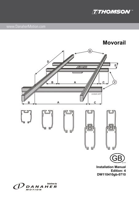
2. The components of the <strong>Movorail</strong> system<br />
2.1 System with main girder rails<br />
Figure 1: system with main girder rails<br />
1. I-beam clamps type VBKLA: used to suspend a rail directly to an I-beam.<br />
2. Single main girder rail<br />
3. <strong>Movorail</strong> rail: load carrying profile which comes in five sizes: SPR 85, SPR 125, SPR 160A, SPR 295B<br />
and SPR 295W.<br />
4. Flexible suspension type DBSU: suspension type that allows some misalignment between the I-beam<br />
and the rail.<br />
5. Locating pin: a pin that guides the rails at connections.<br />
6. Reinforcement profile: a profile that is used to reinforce profile SPR 160A.<br />
7. Bogie trolley: trolley with horizontal wheels for guidance that is used for hanging loads.<br />
8. BUB: attachment between bogie trolleys, distance girders and rails.<br />
9. Yoke: frame in which a hoist or other loads can be suspended.<br />
10. Down shop rails: the non-moving rails to which the suspensions are attached.<br />
11. Span: the c/c distance between two down shop rails.<br />
12. Current track: rail with copper conductors installed inside of the <strong>Movorail</strong> profile.<br />
13. Distance girder: two types exist, flexible or rigid.<br />
14. End plate<br />
15. End stop<br />
16. Double main girder rails<br />
17. Connection<br />
6 DW110410gb-0710 Edition: 4 Installation Manual
<strong>Movorail</strong> MARCH 2007 THOMSON<br />
2.2 Single down shop rail<br />
Figure 2: single down shop rail system<br />
18. Rail and trolley c<strong>ab</strong>le attachment (kit): components that fix c<strong>ab</strong>les to the end of a rail and a trolley.<br />
19. C<strong>ab</strong>le: the type of c<strong>ab</strong>le/hose determines the type of c<strong>ab</strong>le trolley.<br />
20. C<strong>ab</strong>le trolley<br />
21. Cr<strong>ab</strong> trolley<br />
22. Service section: a hatch that facilitates the service of trolleys and other components at long rails.<br />
23. End stop<br />
24. End plate support: a component used to attach the end plate to when the end stop is not placed in the<br />
end of the rail.<br />
Installation Manual DW110410gb-0710 Edition: 4 7
<strong>Movorail</strong> MARCH 2007 THOMSON<br />
3. The <strong>Movorail</strong> rails<br />
3.1 Rails<br />
There are five different straight rail sizes, SPR 85, SPR 125, SPR160A, SPR295B (with reinforcement profile)<br />
and SPR295W (with welded reinforcement profile). Further to this sizes 85, 125 and 160A also comes<br />
in a curved versions (SPB). The reinforcement profile SPF 135 can also be delivered separately and be<br />
installed afterwards on top of a SPR 160A with the aid of the T-slot profile TSS to create a rail of type<br />
SPR295B. The max. allowed load for each profile depends on the distance between the suspensions, see<br />
point 18.3.<br />
For installations to the T-slots of the rails there is a series of T-slot bolts in different lengths. Size TBM 8 is<br />
used for SPR 85 while TBM 12 is used for the others. Note! Only this type of bolt may be used for attachments<br />
to the rail T-slots.<br />
Figure 3: profiles and T-slot bolts<br />
3.2 Attachment of reinforcement profile type SPF 135<br />
Figure 4: how to secure the T-slot profile<br />
At SPR295B or at installation of reinforcement profile in the reinforcement profile must be fixed so that it can<br />
not move. Installing T-slot bolts on both sides of the reinforcement profile prevents it from moving.<br />
8 DW110410gb-0710 Edition: 4 Installation Manual
<strong>Movorail</strong> MARCH 2007 THOMSON<br />
4. Connection of rails<br />
4.1 Connection of straight rails type SPR<br />
Figure 5: connection of straight rails<br />
1. Assemble the connection.<br />
2. Push the connection on to the rail.<br />
3. Glue the locating pins to the rail using the glue supplied with the connection. Also see below t<strong>ab</strong>le.<br />
4. Push the other rail on to the locating pins.<br />
5. Do not glue the locating pins in this end!<br />
6. Pull over the connection (6) from the first rail to the other until the connection is exactly in the middle<br />
and then tighten all bolts according to the t<strong>ab</strong>le in point 18.2. Note! Keep in mind that each connection<br />
must be supported by a suspension.<br />
SPR 85 SPR 125 / SPR 160A / SPR 295B / SPR 295W<br />
L (mm) 30 40<br />
T<strong>ab</strong>le 1: projecting length of the locating pins<br />
4.2 Connection of curves type SPB<br />
Connection of curves is done the same way as for straight but with special curve connections (SK 85R/B<br />
and SK 125/160AR/B). Note! Keep in mind that both the connections and the curve must be supported by a<br />
suspension. This means that at least three suspensions must be used per curve.<br />
Figure 6: connection of curved rails<br />
Installation Manual DW110410gb-0710 Edition: 4 9
<strong>Movorail</strong> MARCH 2007 THOMSON<br />
5. Service sections<br />
5.1 Installation and inspection of service sections type SSKT<br />
Figure 7: installation of service section<br />
1. Suspend the service section using one suspension on each side. Maximum allowed distance (Lmax.) is<br />
400 mm for SPR 85 and 500 mm for SPR 125 / SPR 160A.<br />
2. Remove the indicated socket head cap screws.<br />
3. Test the function of the hatch. Adjust if necessary. Put back the socket head cap screws.<br />
4. Test the function of the section by running the types of trolleys that will be used trough the section.<br />
5. The hatch can, when it is open, be completely removed by knocking out the hinge pins from the hatch to<br />
the sides of the hatch.<br />
10 DW110410gb-0710 Edition: 4 Installation Manual
<strong>Movorail</strong> MARCH 2007 THOMSON<br />
6. Trolleys and accessories for trolleys<br />
6.1 Trolleys<br />
Figure 8: trolleys<br />
1. Cr<strong>ab</strong> trolleys: this type of trolley is used when only hanging loads (the force pointing downwards) shall<br />
be moved i.e. as for hoists.<br />
2. Bogie trolleys: this type of trolley is used when both hanging loads and lateral forces can be present,<br />
i.e. as for crane rails or systems with curves.<br />
3. Bogie trolleys with lower support rollers: this type of trolley can manage hanging loads, lateral<br />
forces and upward forces.<br />
4. Pick up trolleys: this type of trolley is used when a rail is equipped with current track. STV5 can be<br />
used alone while STVG5 must be connected to another trolley with the help of the cardan joint, see<br />
point 6.4.<br />
5. Motor trolleys: this type of trolley is used to motorise the movement in X or Y direction and is avail<strong>ab</strong>le<br />
in several speed versions.<br />
6. C<strong>ab</strong>le trolley: this type of trolley is used to move c<strong>ab</strong>les along a rail. The c<strong>ab</strong>le trolley is at the delivery<br />
equipped with a c<strong>ab</strong>le clamp, a strap or a c<strong>ab</strong>le tie for round c<strong>ab</strong>les, flat c<strong>ab</strong>les or hoses.<br />
Installation Manual DW110410gb-0710 Edition: 4 11
<strong>Movorail</strong> MARCH 2007 THOMSON<br />
6.2 Installation of rail and trolley attachments type KFFB, KFKK, KFVS and KFSB<br />
Figure 9: installation of rail and trolley attachments<br />
1. Install the trolley c<strong>ab</strong>le attachment (a) to the installation holes of the trolley. The picture shows a c<strong>ab</strong>le<br />
attachment with a flat c<strong>ab</strong>le clamp. C<strong>ab</strong>le attachments with other clamp types exist, however, they are<br />
all installed in the same way. Also install the motion limiter plate (b) to the trolley if a motion limiter will<br />
be used (see point 7.2).<br />
2. The rail c<strong>ab</strong>le attachment is installed on the end stop (a) or to the end plate support (b) depending on<br />
how the rail is equipped.<br />
3. Examples of complete installations. Also see point 7.1 and 7.2 for instructions on the installation of end<br />
stops, end plate supports and motion limiters.<br />
12 DW110410gb-0710 Edition: 4 Installation Manual
<strong>Movorail</strong> MARCH 2007 THOMSON<br />
6.3 Adjustment of bogie trolley type BGV 300 HSE with support rollers<br />
Figure 10: adjustment of bogie trolley support rollers<br />
The position of the support rollers on bogie trolleys type BGV 300 HSE must be checked after installation. If<br />
the distance between the support rollers is less than 0,1 mm anywhere along the entire length of the rail the<br />
roller positions must be adjusted. To adjust, loosen the lock screws (1) and turn the eccentric shaft of the<br />
rollers (2) until the distance between the rollers is within the limit all along the rail. Tighten the lock screw<br />
when the adjustment is done. The tightening torque of the lock screws should be 5 Nm.<br />
Installation Manual DW110410gb-0710 Edition: 4 13
<strong>Movorail</strong> MARCH 2007 THOMSON<br />
6.4 C<strong>ab</strong>le trolleys type KBV, KBVA and KBVS<br />
Figure 11: c<strong>ab</strong>le trolleys<br />
C<strong>ab</strong>le trolley type KBV + FB<br />
C<strong>ab</strong>le trolley type KBV + FB is intended to be used to flat c<strong>ab</strong>les.<br />
C<strong>ab</strong>le trolley type KBV + KUL<br />
C<strong>ab</strong>le trolley type KBV + KUL is intended to be used to round c<strong>ab</strong>les. The trolley must be completed with<br />
c<strong>ab</strong>le clamps of type KK in suit<strong>ab</strong>le dimension. A maximum of two c<strong>ab</strong>le clamps can be installed to the trolley.<br />
C<strong>ab</strong>le trolley type KBVA + KUL<br />
C<strong>ab</strong>le trolley type KBVA + KUL is intended to be used to round c<strong>ab</strong>les. The trolley must be completed with<br />
c<strong>ab</strong>le clamps of type KK in suit<strong>ab</strong>le dimension. As many c<strong>ab</strong>le clamps as needed can be installed to the<br />
trolley as long as the load do not exceed 50 kg.<br />
C<strong>ab</strong>le trolley type KBVS<br />
C<strong>ab</strong>le trolley type KBVS is intended to be used to round c<strong>ab</strong>les which is fixed by the strap.<br />
C<strong>ab</strong>le trolley type KBV + KUL + SB<br />
C<strong>ab</strong>le trolley type KBV + KUL + SB is intended to be used to hoses that are fixed with the c<strong>ab</strong>le tie. The<br />
c<strong>ab</strong>le tie accepts hoses with a diameter of 30 – 80 mm.<br />
C<strong>ab</strong>le clamps type KK<br />
C<strong>ab</strong>le clamps type KK are avail<strong>ab</strong>le in three sizes, for c<strong>ab</strong>les with a diameter of 10 – 16 mm, 17 – 25 mm<br />
and 26 – 36 mm. The clamps are installed on top of each other in the maximum amount that the trolley type<br />
accepts.<br />
14 DW110410gb-0710 Edition: 4 Installation Manual
<strong>Movorail</strong> MARCH 2007 THOMSON<br />
6.5 Pick up trolleys type STV5 and STVG5<br />
STV5 is intended for rail SPR 85 and can carry loads up to 50 kg. STV5 can be connected to other trolley if<br />
needed. STVG5 comes in two versions, STVG5-125 for rail SPR 125 and STVG5-160A for SPR 160A, SPR<br />
295 B and SPR 295W. This trolley must always be connected to another trolley via the cardan joint, which is<br />
included in the delivery. Never exceed the current limits of the pick up brushes/current track, see point 18.4.<br />
Figure 12: connection of pick up trolley<br />
A. STV5<br />
1. The load-carrying pin can be placed in any of the holes (h1, h2, or h3). Max. load = 50 kg.<br />
2. The strain relief plate can be placed in any of the holes (h1, h2 or h3).<br />
3. Adjustment screw for the contact pressure of the brushes. Adjust the brushes to ensure good contact.<br />
Clean if necessary the brushes from any oxide. Connect the c<strong>ab</strong>le according to the below t<strong>ab</strong>le.<br />
4. If needed, connect STV5 to another trolley by means of the cardan joint MBE1B (not included in STV5).<br />
5. C<strong>ab</strong>le 4 × 1,5 mm 2 .<br />
B. STVG5<br />
1. Connect STVG5 to the load carrying trolley.<br />
2. Adjustment screw for the contact pressure of the brushes. Adjust the brushes to ensure good contact.<br />
Clean if necessary the brushes from any oxide. Connect the c<strong>ab</strong>le according to the below t<strong>ab</strong>le.<br />
3. C<strong>ab</strong>le 4 × 1,5 mm 2 .<br />
C. Connection of c<strong>ab</strong>le to pick up trolley<br />
a b c d e<br />
1 × 230 VAC Earth (PE) L1 N L1 Earth (PE)<br />
3 × 400 VAC Earth (PE) L1 L2 L3 Earth (PE)<br />
C<strong>ab</strong>le lead Yellow / green 1 2 3 –<br />
T<strong>ab</strong>le 2: connection of c<strong>ab</strong>le on pick up trolley<br />
Installation Manual DW110410gb-0710 Edition: 4 15
<strong>Movorail</strong> MARCH 2007 THOMSON<br />
6.6 Installation of motor trolleys type TMT<br />
Figure 13: installation of motor trolleys<br />
Installation order for motor trolleys.<br />
1. Lower the drive wheel, see point 6.8.<br />
2. Set the correct profile size, see point 6,8.<br />
3. Connect possible trolley to the motor trolley<br />
using the cardan joint. Use MBE1B if curved<br />
rails are used and MBE3 if only straight rails<br />
are used.<br />
4. Insert the motor trolley into the rail.<br />
6.7 Adjustment of centre of gravity on motor trolley type TMT<br />
Figure 14: centre of gravity adjustment<br />
Adjust the counter weight so that the trolley hangs perpendicular.<br />
5. Attach the load to the trolley (never attach any<br />
load to the motor trolley itself).<br />
6. Check the centre of gravity, see point 6.7.<br />
7. Connect the supply and the motor.<br />
8. Adjust the drive wheel contact pressure, see<br />
point 6.7.<br />
9. Test run, see point 6.8.<br />
16 DW110410gb-0710 Edition: 4 Installation Manual
<strong>Movorail</strong> MARCH 2007 THOMSON<br />
6.8 Electrical connection and adjustment of motor trolleys type TMT<br />
Figure 15: connection and adjustment<br />
1. Connect the motor c<strong>ab</strong>le.<br />
2. Adjust the spring pressure to obtain slip free drive wheel operation.<br />
3. Set the eccentric screw to the correct position for the profile size being used.<br />
4. If pneumatic release is being used, make sure the operating pressure is max. 5 bar.<br />
5. Install the pneumatic release cylinder sensor bracket as shown.<br />
Installation Manual DW110410gb-0710 Edition: 4 17
<strong>Movorail</strong> MARCH 2007 THOMSON<br />
7. End plates, end stops, motion limiters and Walter bolts<br />
7.1 End stops type STP, end plates type TPL and end plate supports type EPF<br />
Figure 16: installation of end stop, end plate and end plate support<br />
All rails should be equipped with end plates (1) and end stops (2) in both ends. If the end stop is installed a<br />
bit from the end (3) an end plate support (4) can be installed in the rail as a support for the end plate.<br />
7.2 Motion limiter type BGR<br />
Figure 17: installation of motion limiter<br />
Motion limiters (1) are used to create a buffer zone for c<strong>ab</strong>le trolleys in a rail end. How long the buffer zone<br />
needs to be depends on the number and type of c<strong>ab</strong>le trolley being used. For information on how to calculate<br />
the number of c<strong>ab</strong>le trolleys, see point 15.1.<br />
One or two holes needs to be drilled (the number of holes depends on the rail type) in the centre of the Tslot<br />
of the rail to be <strong>ab</strong>le to install the motion limiter. For drilling data, see the t<strong>ab</strong>le below. On trolleys that<br />
will work against a motion limiter there must be a motion limiter plate (2) installed. Also see point 6.2. Check<br />
that no suspension bolts will be located at the same place as the motion limiter.<br />
BGR 85 BGR 125 / BGR 160A<br />
A 38 mm 60 mm<br />
B – 36 mm<br />
ø 1 × 9 mm 2 × 13 mm<br />
T<strong>ab</strong>le 3: drill measures for motion limiters<br />
18 DW110410gb-0710 Edition: 4 Installation Manual
<strong>Movorail</strong> MARCH 2007 THOMSON<br />
7.3 Walter bolt type WBM<br />
Figure 18: installation of Walter bolt and end stop<br />
1. Holder for the rubber bumper<br />
2. Lock plate<br />
3. Bolt<br />
4. Walter bolt (bolt, washer and nut)<br />
5. End plate screws (2×)<br />
The Walter bolt is used to enhance the safety of the system, as it will make it impossible to push the end<br />
stop out of the rail. See the t<strong>ab</strong>le below for the position and the diameter of the hole. Do not deform the rail<br />
when tightening the bolt.<br />
SPR 85 SPR 125 SPR 160A / SPR 295B / SPR<br />
295W<br />
L (mm) 49 52 56<br />
Ø (mm) 12,5 12,5 12,5<br />
T<strong>ab</strong>le 4: drilling position of the hole for Walter bolts<br />
Installation Manual DW110410gb-0710 Edition: 4 19
<strong>Movorail</strong> MARCH 2007 THOMSON<br />
8. Location of suspensions<br />
9.1 Location of suspensions<br />
Figure 19: suspension points<br />
The <strong>ab</strong>ove figure shows at which points it is necessary to install suspensions for different types of systems.<br />
It may also be necessary to use more suspensions in order to keep the deflection of the rails within the permissible<br />
limits. See the diagram in point 18.3.<br />
1. Rail ends: always install a suspension at the ends of each rail.<br />
2. Connections: each connection must be supported by a suspension placed directly on to the connection.<br />
3. Curves: each curve must be suspended by at least one suspension in the centre of the curve.<br />
4. Service sections: each service section must be suspended by at least two suspensions, one on each<br />
side of the hatch. Also see point 5.1.<br />
20 DW110410gb-0710 Edition: 4 Installation Manual
<strong>Movorail</strong> MARCH 2007 THOMSON<br />
9. Suspensions<br />
9.1 General <strong>ab</strong>out suspensions<br />
Never use any suspensions or fixing material in any other way than recommended in this manual. Check<br />
that the beams and suspension points that will be used can carry the maximum load of the system (max.<br />
load to lift + weight of system). Furthermore may no suspension be exposed to higher side forces than 10 %<br />
of the permissible max. load. Tighten all bolts according to the t<strong>ab</strong>le in point 18.2.<br />
We recommend that each suspension and its attachments should be thoroughly inspected by someone<br />
with adequate knowledge before the system is tested or used.<br />
9.2 Z-suspension type DZ<br />
Figure 20: installation of DZ<br />
1. Nut<br />
2. Washer<br />
3. Z-profile<br />
4. Clamp<br />
5. Bolt<br />
Z-suspensions are installed directly to the T-slot in the rail and is attached to the roof or a roof beam. Max.<br />
load for DZ 85 is 1000 N while DZ 125/160A manage 6000 N.<br />
9.3 I-beam clamps typ VBKLA<br />
Figure 21: installation of VBKLA<br />
1. Nut<br />
2. Washer<br />
3. Sliding washer<br />
4. Clamp<br />
5. T-slot profile<br />
6. Bolt<br />
I-beam clamps are installed directly to the T-slot in the rail and are attached to a beam flange. Max. load for<br />
VBKLA 85 is 1000 N while VBKLA 125/160A manage 6000 N. I beam clamps type VBKLA accepts a beam<br />
flange thickness (L) from 5 – 20 mm. I-beam clamps type VBKLA can not be installed on a connection.<br />
Installation Manual DW110410gb-0710 Edition: 4 21
<strong>Movorail</strong> MARCH 2007 THOMSON<br />
9.4 Flexible suspensions type DBSU<br />
Figure 22: installation of DBSU<br />
Flexible suspensions are installed either to the T-slot of the rail (as shown for DBSU 85-100) or on a connection<br />
(as shown for DBSU 125/160A-600). Two of the bolts of the connection are used in the later case to<br />
fit the bracket to the connection. The suspension is then attached to a beam flange. This type of suspension<br />
can be installed in any angle in relation to the rail. Max. load for DBSU 85-100 is 1000 N while it for DBSU<br />
125/160A –600 is 6000 N.<br />
Fit the cube (1) and the spacer sleeve (2) to the suspension profile (3). Then fit the I-beam clamps (4) to<br />
the suspension profile. Attach the suspension profile to the beam flange with the I-beam clamps. Fit the<br />
bracket (5) to the <strong>Movorail</strong> profile or to the connection. Fit the bracket to the cube with the aid of the cylindrical<br />
pin (6). Secure the pin with the split cotter pins.<br />
If this type of suspension is installed both directly on to the rail and on connections in the same system, the<br />
supplied washers must be placed between the rail and the bracket on those suspensions installed directly<br />
on the rail to keep the rail horizontally aligned over the whole length.<br />
9.5 Adjust<strong>ab</strong>le suspensions type ASU<br />
Figure 23: installation of ASU<br />
Adjust<strong>ab</strong>le suspensions are installed either to the T-slot of the rail (A) or on a connection (B). Two of the Tslot<br />
bolts of the connection are used in the later case to fit the plate to the connection. The suspension is<br />
then attached to a beam flange. This type of suspension can be installed in any angle in relation to the rail<br />
and be adjusted 50 mm in height. Max. load is 6000 N.<br />
Fit the socket head cap screw and the sleeve (1) to the suspension profile (2). Fit the two plates and the<br />
adjustment screws (3) to the suspension profile. Then fit the I-beam clamps (4) to the suspension profile.<br />
Attach the suspension profile to the beam flange with the I-beam clamps. At installations directly on the rail<br />
the two T-slot bolts (5), which is supplied with the suspension, must be used to attach the rail to the suspension.<br />
There must also be a washer (6) between the nuts and the lower plate. At installations on a connection<br />
the two bolts in the centre of the connection are used instead and no washer should be installed between<br />
the nuts and the lower plate.<br />
22 DW110410gb-0710 Edition: 4 Installation Manual
<strong>Movorail</strong> MARCH 2007 THOMSON<br />
10. Safety c<strong>ab</strong>les for suspensions<br />
10.1 Safety c<strong>ab</strong>le type SLU<br />
Figure 24: installation of safety c<strong>ab</strong>le type universal<br />
Safety c<strong>ab</strong>les type SLU are used to enhance the safety of suspensions. The safety c<strong>ab</strong>le is put around any<br />
safe point that can support the load, such as a roof beam. The L-profiles makes it possible to add safety<br />
c<strong>ab</strong>les to a system at any time without any disassembly. The c<strong>ab</strong>le is 1,5 m long and is cut to fit the application.<br />
The c<strong>ab</strong>le should be installed with a minimum of slack so that the fall height is minimised.<br />
Insert the L-profiles (a) one by one in to the T-slot of the profile. Then put the c<strong>ab</strong>le (b) trough the holes in<br />
the L-profiles and put the c<strong>ab</strong>le around the safe point (beam, roof beam etc.) Connect the ends of the c<strong>ab</strong>le<br />
using the c<strong>ab</strong>le locks. Install the c<strong>ab</strong>le locks with a distance between them and with a length of the projecting<br />
ends corresponding at least to the figure <strong>ab</strong>ove.<br />
1. C<strong>ab</strong>le<br />
2. C<strong>ab</strong>le locks (a minimum of two locks must be used)<br />
3. L-profiles<br />
Rail C<strong>ab</strong>le designation C<strong>ab</strong>le diameter (d)<br />
SPR 85 SLU4 4 mm<br />
SPR 125 / SPR 160A / SPR 295B / SPR 295W<br />
T<strong>ab</strong>le 5: c<strong>ab</strong>le diameter<br />
SLU6 6 mm<br />
Installation Manual DW110410gb-0710 Edition: 4 23
<strong>Movorail</strong> MARCH 2007 THOMSON<br />
11. Installation of current track<br />
11.1 General <strong>ab</strong>out current track<br />
The current track is installed in the <strong>Movorail</strong> rails. The supply to the current track is connected to the power<br />
supply track that is installed in one of the rail ends. Sometimes, however, it may be necessary to install<br />
power supply tracks in both ends of the current track, due to the power required. See below figure.<br />
Carry out the electrical connections to the current track as described in point 11.5. Make sure that the<br />
voltage and current that will be transmitted in the current track lies within the permissible limits. See t<strong>ab</strong>le in<br />
point 18.4. A qualified electrician must carry out all electrical connections.<br />
11.2 Installation of current track type SB<br />
Figure 25: components to current track<br />
If the current track is not delivered from factory cut to fit the total length of the rails, it may be necessary to<br />
cut one of the current tracks to make the total track length the same as the total rail length. This operation is<br />
also necessary as the track ends only can be fitted to a straight track end and not to a track end used for<br />
track connections, see point 11.4. Never cut a power supply track. Also drill a hole in the aluminium profile<br />
at the power supply track to be used for earthing of the <strong>Movorail</strong> profile. Also see point 11.5.<br />
1. Track end type EST 5 + LED 5<br />
2. Current tracks type SB, cut<br />
3. Track connection type ATSK 5<br />
4. Current track type SB, uncut<br />
5. Power supply track type ATSA 5<br />
6. C<strong>ab</strong>le<br />
7. End plate type TPL<br />
8. Place of cut<br />
9. C<strong>ab</strong>le clip, see point 11.5<br />
10. Hole for earthing of the rail, see point 11.5<br />
11. Hole for earthing of the end plate, see point 11.5<br />
12. End plate type TPLH with c<strong>ab</strong>le gland PG16<br />
13. Example of power supply at both ends<br />
24 DW110410gb-0710 Edition: 4 Installation Manual
<strong>Movorail</strong> MARCH 2007 THOMSON<br />
11.3 Insertion of current track in to the <strong>Movorail</strong> profile<br />
Figure 26: insertion of current track<br />
The current track is inserted in to the grooves in the profile. Use the top grooves in SPR 125! Install the<br />
current tracks before any trolleys are inserted into the profile. The track end of the first current track can be<br />
slightly chamfered to simplify the insertion. Chalk can be used as lubricant to reduce the friction. Never use<br />
any oil or silicone based products as lubricants.<br />
11.4 Connection of current tracks with current track connection type ATSK 5<br />
Figure 27: connection of current tracks<br />
Insert the plastic pins LED 5 (1) in the track end (2). Attach the track end with the aid of the two screws (3)<br />
to the end of the first current track / power supply track (4) and then insert the track into the profile until the<br />
first connection. Insert the four insulation pieces (5) in to the first current track and put together the next<br />
current track (6) with the first so that the insulation pieces enter both tracks. Snap on the five collars (7) over<br />
the copper conductors and snap on the track connection plate (8) so that rails gets connected. Insert the<br />
connection and the current track until the next connection and repeat the procedure until the whole current<br />
track is installed. At last, install a track end on the finishing current track / power supply track.<br />
Installation Manual DW110410gb-0710 Edition: 4 25
<strong>Movorail</strong> MARCH 2007 THOMSON<br />
11.5 Electrical connection of current tracks with power supply track type ATSA 5<br />
Figure 28: electrical connection of current track<br />
The power supply track ATSA 5 has five connection points for c<strong>ab</strong>le clips. The two outer are for screw connection<br />
while the three in the centre are for pin connection.<br />
Proper earthing is important for the safety. Connect earth to the pre-drilled M3 Hole in the end plate (1)<br />
and to the profile (2). At every connection (3) an earth c<strong>ab</strong>le (4) should be installed over the connection in<br />
order to earth the whole rail. This requires the drilling of a hole in the beginning of each rail and at each side<br />
of a connection. Clean the end plate and the profile from any oxide and anodising before the earth leads are<br />
connected to ensure good contact. Carry out the connections to the current track according to the figure and<br />
the t<strong>ab</strong>le. At last, affix a warning sign (5) at both ends of the rail.<br />
If the track has been stored before it is installed, it may be need to be cleaned from oxide before it is used.<br />
Spray along the track with a contact spray, e.g. Electrolube SOB, Scotch 1607 or equivalent. Let the spray<br />
work for a while before using the track. Never spray with the power on.<br />
A B C D E<br />
Supply 1 × 230 VAC PE L1 N L1 PE<br />
Supply 3 × 400 VAC PE L1 L2 L3 PE<br />
C<strong>ab</strong>le with number leads Yellow/green 1 2 3 Yellow/green<br />
C<strong>ab</strong>le with colour leads Yellow/green Brown Black Black/white Yellow/green<br />
T<strong>ab</strong>le 6: connection of power supply track<br />
26 DW110410gb-0710 Edition: 4 Installation Manual
<strong>Movorail</strong> MARCH 2007 THOMSON<br />
12. Flexible bolt connection for trolleys and trolley safety c<strong>ab</strong>le<br />
12.1 Installation of flexible bolt connections type BUB between trolleys and crane rail<br />
Figure 29: flexible bolt connections type BUB<br />
1. Split cotter pin 5. Plastic washer<br />
2. Lock nut 6. Distance sleeve<br />
3. Nut 7. Lower washer (chamfer up)<br />
4. Upper washer (BUB 85 = chamfer up, BUB 125/160A = chamfer down) 8. T-slot bolt<br />
BUB:s should always be used to attach a trolley to a rail, never replace them by another component. Also<br />
always install the safety c<strong>ab</strong>le supplied with the BUB, see below. Note! Check so that the chamfer of the<br />
washers are correctly positioned and that the plastic washer is not stuck between the upper washer and the<br />
distance sleeve! Use the correct tightening torque. See t<strong>ab</strong>le 7 below.<br />
Tightening torque BUB<br />
85<br />
BUB 125/160A<br />
Dry threads (Nm) 23,0 77,8<br />
Oiled threads (Nm) 20,6 69,7<br />
T<strong>ab</strong>le 7: BUB tightening torque<br />
12.2 Installation of trolley safety c<strong>ab</strong>le type SLV<br />
Figure 30: safety c<strong>ab</strong>le type SLV<br />
A trolley safety c<strong>ab</strong>le type SLV is supplied with each BUB and shall be installed together with it. Two sizes<br />
exist, SLV4 for rail SPR 85 and SLV6 for SPR 125, SPR 160A, SPR 295B and SPR 295W. Install the c<strong>ab</strong>le<br />
(1) trough the trolley and attach it to the rail using its loops and the two T-slot bolts (2).<br />
Installation Manual DW110410gb-0710 Edition: 4 27
<strong>Movorail</strong> MARCH 2007 THOMSON<br />
12.3 Installation of flexible bolt connections type TBUB between trolleys and crane rail<br />
Figure 31: flexible bolt connection type TBUB<br />
1. Nut 5. Plastic washer 9. <strong>Movorail</strong> profile<br />
2. Washer 2 x 6. Beam whit pin 10. Trolley<br />
3. Upper beam 7. T-slot profile 11. Trolley load attachment beam<br />
4. Distance sleeve 8. Bolt 12. <strong>Movorail</strong> profile<br />
TBUB:s are used to connect a trolley to a rail. Put the plastic washer (a) on to the trolley load attachment<br />
and put the upper beam (b) in place. Then insert the T-slot profiles (c) which are put on the bolts (d) in to the<br />
<strong>Movorail</strong> profile. Adjust the bolts (e) so that the beam with the pin (f) and the distance sleeved can be placed<br />
on the bolts. Push up the <strong>Movorail</strong> profile and fix it to the trolley by means of the washers (i) and nuts (j).<br />
Tighten the bolts with the correct torque. For dry bolts use 77,8 Nm and for oiled 69.7 Nm.<br />
28 DW110410gb-0710 Edition: 4 Installation Manual
<strong>Movorail</strong> MARCH 2007 THOMSON<br />
13. Crane distance trolley and distance girders<br />
13.1 Flexible distance girder type DNS<br />
Figure 32: flexible distance girder type DNS<br />
The flexible type of distance girder separates two crane rails of type SPR 125, SPR 160A, SPR 295B or SPR<br />
295W. The rails may move around the BUB. The distance girder (a) is attached by two BUB:s 125/160A (b).<br />
For installation of BUB 125/160A, see point 12.1.<br />
13.2 Rigid distance girder type SD<br />
The rigid type of distance girder separates two crane rails of type SPR 125, SPR 160A, SPR 295B or SPR<br />
295W. The rails are fixed in relation to each other. Except from this the rigid type of distance girder is installed<br />
and functioning in the same way as the flexible with the exception that four T-slot bolts are used for<br />
the attachment instead for two BUB:s.<br />
Installation Manual DW110410gb-0710 Edition: 4 29
<strong>Movorail</strong> MARCH 2007 THOMSON<br />
14. Switches and turnt<strong>ab</strong>les<br />
14.1 General <strong>ab</strong>out switches and turnt<strong>ab</strong>les<br />
Switches and turnt<strong>ab</strong>les are delivered completely assembled. If a current track kit is ordered to the switch<br />
(SBHX or SBVX) or the turnt<strong>ab</strong>le (SBVS), then this is installed as well.<br />
Switches and turnt<strong>ab</strong>les are operated pneumatically. The air pressure must be at least 6 bar. We recommend<br />
only using filtered air.<br />
When a switch or a turnt<strong>ab</strong>le is installed it is important to adjust them so that the trolleys can pass them<br />
without problems.<br />
14.2 Switches type HXL and VXL<br />
Figure 33: installation of switch (seen from <strong>ab</strong>ove)<br />
Switches come in a right (HXL) and a left (VXL) version. The switches are suspended from the six suspension<br />
holes (1). The connection rail (2) must be used in order to connect the rail system to the curved rail<br />
section in the switch. This rail is 1000 mm long and is included in the switch delivery.<br />
14.3 Turnt<strong>ab</strong>les type VSL<br />
Figure 34: installation of turnt<strong>ab</strong>les<br />
Turnt<strong>ab</strong>les are suspended from the four suspension holes (1).<br />
30 DW110410gb-0710 Edition: 4 Installation Manual
<strong>Movorail</strong> MARCH 2007 THOMSON<br />
15. C<strong>ab</strong>le loop<br />
15.1 Installation of c<strong>ab</strong>le loop<br />
Figure 35: c<strong>ab</strong>le loop<br />
C<strong>ab</strong>le loop can be done with flat c<strong>ab</strong>le (1), round c<strong>ab</strong>le (2) or hose (2). The same calculations are used for<br />
all types of c<strong>ab</strong>les and hoses to calculate the necessary number of trolleys, the buffer zone length and the<br />
length of the c<strong>ab</strong>les.<br />
Always check so that the trolleys roll on their wheels and not are lifted up in the rail by the c<strong>ab</strong>les or the<br />
hose. Always use flexible c<strong>ab</strong>les or hoses which are made for continuos motion and that can withstand the<br />
environment in question. If in doubt, contact your c<strong>ab</strong>le or hose supplier.<br />
Select the conductor cross-section area with respect to the power that will be transmitted. Keep in mind<br />
that long c<strong>ab</strong>les may result in a voltage drop that necessitates the use of a greater conductor cross-section.<br />
See point 18.6. Avoid using c<strong>ab</strong>les with less conductor cross-section than 1 mm² as they may break due to<br />
the forces acting on the c<strong>ab</strong>le.<br />
Number of trolleys Length of buffer zone Length of c<strong>ab</strong>les<br />
n = Lt / (Lh × 2) Lb = n × Lv Lc = Lt + Lb × 1,15<br />
Lt = total length of travel for c<strong>ab</strong>les<br />
Lb = length of buffer zone<br />
n = necessary trolley quantity<br />
Lc = length of c<strong>ab</strong>les (hoses) in the loop<br />
Lh = loop height (600 – 800 mm is recommended)<br />
Lv = length of c<strong>ab</strong>le trolley being used<br />
Installation Manual DW110410gb-0710 Edition: 4 31
<strong>Movorail</strong> MARCH 2007 THOMSON<br />
16. Testing the <strong>Movorail</strong> system<br />
16.1 General <strong>ab</strong>out testing of the <strong>Movorail</strong> system<br />
The system must be tested when the installation is completed. Follow all applic<strong>ab</strong>le instructions below.<br />
Please note that national and international regulations may call for further tests. The test area should be<br />
closed during all tests, only persons who are involved in the testing procedures may enter the area.<br />
16.2 Inspection points at a test of a <strong>Movorail</strong> system<br />
Figure 36: inspection of the system<br />
1. Check the system against the drawing, if any is avail<strong>ab</strong>le.<br />
2. Make sure the system is marked with an adequate number of max. load sign.<br />
3. Check the span (a). Max. permissible parallel deviation between the rails is ± 2 mm.<br />
4. Check so that there is no gap between the rails at the connections (b).<br />
5. Check so that no rails are deformed or that they are subjected to any twisting or bending forces.<br />
6. Check the tightening torque for all bolt connections, BUB;s, suspensions, connections and safety c<strong>ab</strong>les.<br />
7. Test any electrical systems. Perform at least a continuity check of the bonding circuit, an insulation resistance<br />
test and a voltage test. Also make sure that the system is equipped with a lock<strong>ab</strong>le main switch<br />
placed beside it and that warning signs for electrical equipment are applied.<br />
8. Run the system without load. Check all functions. Adjust.<br />
9. Run the system with 25 % overload. Check all functions. Check all critical components after the test,<br />
especially bolt connections.<br />
10. If rails of type SPR 295W are used, check so that there is no cracks in the weldings between the upper<br />
and the lower rail.<br />
11. At last, check all rail and trolley tolerances again. Adjust if necessary.<br />
32 DW110410gb-0710 Edition: 4 Installation Manual
<strong>Movorail</strong> MARCH 2007 THOMSON<br />
17. Training and user instructions<br />
17.1 General <strong>ab</strong>out training<br />
All operators should have the sufficient training before the equipment is taken into use. The training required<br />
depends on the type of equipment and has to be defined on a case to case basis. The following instructions,<br />
however, apply to most types of equipment and are the basic information all users should be given. Also<br />
make sure that all users fulfil the requirements below.<br />
1. Only those who are at least 18 years old may use the equipment.<br />
2. Only those who are authorised by their superiors may use the equipment.<br />
3. Only those who have been trained may use the equipment.<br />
4. Only those who know all safety devices and operating controls of the system may use the equipment.<br />
17.2 User instructions<br />
Figure 37: user instructions<br />
1. Never move people with the system. Never lift loads <strong>ab</strong>ove people.<br />
2. Never force loads that are stuck or jammed, to move.<br />
3. Never apply overload to the system.<br />
4. Avoid lifting loads higher than 1,5 m <strong>ab</strong>ove floor level.<br />
5. Never pull loads along the floor.<br />
6. Never leave hanging loads unattended at any time.<br />
7. Never push loads intentionally into the end stops.<br />
8. Always try to lift loads from their centre of gravity.<br />
9. Wear hard hat, safety shoes and protective gloves at all times.<br />
Installation Manual DW110410gb-0710 Edition: 4 33
<strong>Movorail</strong> MARCH 2007 THOMSON<br />
18. Technical data<br />
18.1 Data for the <strong>Movorail</strong> profiles<br />
SPR 85 SPR 125 SPR 160A SPR 295B SPR 295W SPF 135<br />
Material Anodised extruded aluminium<br />
Colour Natural aluminium<br />
X (mm) 85 125 160 295 295 135<br />
C (mm) 68,8 71,5 73,5 73,5 73,5 70<br />
Standard profile lengths (m) 4 / 5 / 6 / 8 4 / 5 / 6 / 8 4 / 5 / 6 / 8 4 / 5 / 6 / 8 4 / 5 / 6 / 8 3,6 / 4,6 / 5,6<br />
Inertia (cm 4 ) 97 333 812 1368 3700 556<br />
Weight / meter (kg/m) 3 5 7,8 14 14,1 6,2<br />
Profile area (cm 2 ) 11 18,6 28,7 51,5 51,5 22,8<br />
Modulus of elasticity (N/mm 2 ) 70 000 70 000 70 000 70 000 70 000 70 000<br />
T<strong>ab</strong>le 8: profile data<br />
Figure 38: profile dimensions<br />
18.2 Tightening torque for bolts<br />
The t<strong>ab</strong>le is valid for both normal bolts and T-slot bolts. The bolt grade is normally embossed on the bolt<br />
heads, see the figure below. We recommend using at least bolt grade 8.8. Use a calibrated torque wrench to<br />
gauge the torque.<br />
Bolt dimension Grade Zinc-pl. dry Zinc-pl.<br />
oiled<br />
M6 8.8 9,4 Nm 8,4 Nm<br />
M8 8.8 23,0 Nm 20,6 Nm<br />
M10 8.8 45,1 Nm 40,4 Nm<br />
M12 8.8 77,8 Nm 69,7 Nm<br />
M16 12.9 319,6 Nm 286,3 Nm<br />
T<strong>ab</strong>le 9: tightening torque for bolts Figure 39: bolt grade<br />
34 DW110410gb-0710 Edition: 4 Installation Manual
<strong>Movorail</strong> MARCH 2007 THOMSON<br />
18.3 Load diagram for a rail with a single load<br />
Figure 40: diagram for max. recommended distance between suspensions at a single load<br />
The diagram is based on a maximum deflection of 1/500 of the distance between the suspensions (Lmax.)<br />
and shows the maximum recommended distance between the suspensions at a given load.<br />
18.4 Technical data for current track type SB<br />
Max. voltage 400 V Current track conductor cross-section 9 mm²<br />
Protection class IP 21 Max. current track 55 A<br />
Ambient temperature -20°C – + 55°C Max. current connection 25 A<br />
Voltage drop 0,103 V / m @ 25 A Max. current power supply track 25 A<br />
Max. speed straight rails 2 m/s Max. current pick up @ 60 % ED 10 A<br />
Max. speed curved rails 0,5 m/s Max. current pick up @ 100 % ED 6A<br />
T<strong>ab</strong>le 10: technical data for current track<br />
Installation Manual DW110410gb-0710 Edition: 4 35
<strong>Movorail</strong> MARCH 2007 THOMSON<br />
18.5 Voltage drop in c<strong>ab</strong>les<br />
Long c<strong>ab</strong>les may lead to a significant voltage drop that may lead to malfunctioning. To avoid this it may be<br />
necessary to increase the conductor cross-section. The formulas below can be used to calculate the voltage<br />
drop. If the voltage drop exceeds 5 % (Ufactor less than 0,95) of the nominal voltage, a larger crosssectional<br />
area is necessary.<br />
Formula 1. Uend = Ustart - (2 × L × R × Imax)<br />
Formula 2. Uend / Ustart = Ufactor<br />
Formula 3. Ufactor > 0,95 = OK<br />
Ufactor < 0,95 = not OK<br />
Imax = max. current to be transmitted in c<strong>ab</strong>le<br />
Ufactor = voltage drop coefficient<br />
Uend = voltage at the end of the c<strong>ab</strong>le<br />
Ustart = voltage at the start of the c<strong>ab</strong>le<br />
L = length of c<strong>ab</strong>le<br />
R = resistance per meter (see t<strong>ab</strong>le below)<br />
Conductor area Resistance / meter (R)<br />
1 mm 2 0,0175<br />
1,5 mm 2 0,0116<br />
2,5 mm 2 T<strong>ab</strong>le 11: resistivity<br />
0,0070<br />
Example:<br />
If: Ustart = 24 V, L = 40 m, conductor area = 1,5 mm², Imax = 1,5 A<br />
Then: Uend = 24 - (2 × 40 × 0,0116 × 1,5) = 22,608 V<br />
Ufactor = 22,608 / 24 = 0,94<br />
0,94 < 0,95 = not OK, the voltage drop is to large<br />
Conclusion: a larger conductor cross-section is necessary, e.g. try with 2,5 mm².<br />
36 DW110410gb-0710 Edition: 4 Installation Manual
<strong>Movorail</strong> MARCH 2007 THOMSON<br />
- page intentionally left blank –<br />
Installation Manual DW110410gb-0710 Edition: 4 37
<strong>Movorail</strong> MARCH 2007 THOMSON<br />
- page intentionally left blank -<br />
38 DW110410gb-0710 Edition: 4 Installation Manual
<strong>Movorail</strong> MARCH 2007 THOMSON<br />
- page intentionally left blank -<br />
Installation Manual DW110410gb-0710 Edition: 4 39
<strong>Movorail</strong> MARCH 2007 THOMSON<br />
Sales and Service<br />
Danaher Motion products are avail<strong>ab</strong>le world wide through an extensive<br />
authorised Distributor network. These distributors offer literature, technical<br />
assistance and a wide range of models off the shelf for fastest possible<br />
delivery.<br />
Danaher Motion sales engineers are conveniently located to provide prompt<br />
attention to customers' needs. Call the nearest office listed for ordering.<br />
United Kingdom<br />
Danaher Motion<br />
Chartmoor Road, Chartwell Business Park<br />
Leighton Buzzard, Bedfordshire<br />
LU7 4WG; United Kingdom<br />
Phone: +44 (0)1525 243 243<br />
Fax: +44 (0)1525 243 244<br />
E-mail: sales.uk@danahermotion.com<br />
Germany<br />
Danaher Motion GmbH<br />
Sales Office North<br />
Wacholderstr. 40-42<br />
40489 Düsseldorf<br />
Germany<br />
Phone: +49 (0) 203 9979 214<br />
Fax: +49 (0) 203 9979 3214<br />
E-Mail: iris.tolusch@danahermotion.com<br />
Danaher Motion GmbH<br />
Sales Office South West<br />
Brückenfeldstraße 26/1<br />
75015 Bretten<br />
Germany<br />
Phone: +49 (0) 7252 97390 56<br />
Fax: +49 (0) 7252 97390 55<br />
E-Mail: kerstin.mueller@danahermotion.com<br />
Danaher Motion GmbH<br />
Sales Office South East<br />
Kiesgräble 7<br />
89129 Langenau<br />
Germany<br />
Phone: +49 (0) 7471 62 23 23<br />
Fax: +49 (0) 7471 62 23 26<br />
E-Mail: ursula.koschak@danahermotion.com<br />
France<br />
Danaher Motion<br />
C.P 80018<br />
12, Rue Antoine Becquerel – Z.I. Sud<br />
F-72026 Le Mans Cedex 2<br />
France<br />
Phone: +33 (0) 243 50 03 30<br />
Fax: +33 (0) 243 50 03 39<br />
E-mail: sales.france@<strong>tollo</strong>.com<br />
Italy<br />
Danaher Motion srl<br />
Largo Brughetti<br />
I-20030 Bovisio Masciago<br />
Italy<br />
Phone: +39 0362 594260<br />
Fax: +39 0362 594263<br />
E-mail: info@danahermotion.it<br />
Sweden<br />
Danaher Motion<br />
Box 9053<br />
SE-291 09 Kristianstad<br />
Sweden<br />
Phone: +46 (0) 44-24 67 00<br />
Fax: +46 (0) 44-24 40 85<br />
E-mail: helpdesk.kid@danahermotion.com<br />
Switzerland<br />
Danaher Motion SA<br />
La Pierreire 2<br />
1029 Villars-Ste-Croix<br />
Switzerland<br />
Phone: +41 (0) 21 631 33 33<br />
Fax: +41 (0) 21 636 05 09<br />
E-mail: info@danaher-motion.ch<br />
40 DW110410gb-0710 Edition: 4 Installation Manual