Paper title - Surrey Research Insight Open Access - University of ...
Paper title - Surrey Research Insight Open Access - University of ...
Paper title - Surrey Research Insight Open Access - University of ...

Create successful ePaper yourself
Turn your PDF publications into a flip-book with our unique Google optimized e-Paper software.
Connection Fixity Effects On Stress Histories In Riveted Rail<br />
Bridges<br />
B. Imam, T.D. Righiniotis & M.K. Chryssanthopoulos<br />
School <strong>of</strong> Engineering, <strong>University</strong> <strong>of</strong> <strong>Surrey</strong>, Guildford, <strong>Surrey</strong>, UK<br />
ABSTRACT: The riveted type <strong>of</strong> construction is characteristic <strong>of</strong> older railway bridges. As<br />
some <strong>of</strong> these bridges approach, or have even exceeded their theoretical fatigue life under increasing<br />
train loads, it is desirable to improve the procedures available for the assessment <strong>of</strong> fatigue-critical<br />
details. The aim <strong>of</strong> this paper is to present results through the use <strong>of</strong> the FE<br />
method, which address the manner in which assumed conditions <strong>of</strong> fixity <strong>of</strong> bridge riveted joints<br />
affect the resulting internal stresses. Different degrees <strong>of</strong> connection fixity, ranging from fully<br />
fixed to partially fixed, are assigned to the connections. A nominal train is traversed over a UKtypical<br />
bridge configuration and the resulting stress histories are converted into stress ranges using<br />
the rainflow algorithm. By comparing the resulting S-N damage, the extent to which connection<br />
fixity can affect fatigue life predictions is quantified and ranking <strong>of</strong> fatigue-critical details<br />
is undertaken.<br />
1 INTRODUCTION<br />
The majority <strong>of</strong> metallic railway bridges, which are still in use in the United Kingdom and<br />
around the world, are <strong>of</strong> riveted construction. These bridges were constructed <strong>of</strong> wrought iron<br />
and older steels and date back to the second half <strong>of</strong> the 19 th century up to the middle <strong>of</strong> the 20 th<br />
century. The oldest bridges have sustained more than one century <strong>of</strong> continuously increasing<br />
loads and may be close to the end <strong>of</strong> their fatigue lives. Despite this, many <strong>of</strong> these bridges are<br />
still in use, apparently able to cope with current load demands.<br />
As a first step <strong>of</strong> a comprehensive fatigue assessment <strong>of</strong> riveted railway bridges, a global<br />
analysis <strong>of</strong> such bridges is required in order to identify which <strong>of</strong> the connections are the most<br />
critical in terms <strong>of</strong> fatigue damage. However, within the context <strong>of</strong> a global analysis, it is important<br />
to quantify the effect connection fixity has on the resulting stress histories. This paper concentrates<br />
on the finite element analysis <strong>of</strong> a typical riveted railway bridge. This analysis aims to<br />
develop a ranking, on an S-N basis, <strong>of</strong> the various connections with respect to fatigue damage.<br />
Stress histories for all the connections are obtained and compared in order to identify the most<br />
highly stressed one. In particular, the effects <strong>of</strong> different degrees <strong>of</strong> connection fixity on the internal<br />
stresses that develop near these connections are examined.<br />
2 FINITE ELEMENT ANALYSIS<br />
A wide range <strong>of</strong> experimental fatigue tests carried out on full-scale riveted built-up girders and<br />
parts <strong>of</strong> existing riveted bridges have shown that, generally, there is a high degree <strong>of</strong> redundancy<br />
in these members (Fisher et al. 1984, 1990, Mang & Bucak 1990, 1991, Åkesson 1994,<br />
Adamson & Kulak 1995). This fact allows detection and repair <strong>of</strong> cracks before complete failure<br />
<strong>of</strong> the structure. One <strong>of</strong> the fatigue-critical details in riveted railway bridges has been shown<br />
to be the stringer-to-cross-girder connection (Jones et al. 1997, Abouelmaaty et al. 1999, Paasch
& DePiero 1999, Al-Emrani 1999, 2000, 2002, 2003). This type <strong>of</strong> connection, which consists<br />
<strong>of</strong> two angles riveted to each side <strong>of</strong> the stringer web and to the cross-girder web, is shown in<br />
Figure 1. The out-<strong>of</strong>-plane deformation <strong>of</strong> the connection angle and the stress concentration at<br />
the rivet head and shank junction are believed to be the most important factors that contribute<br />
towards fatigue crack initiation in these connections. The stress concentration due to the copehole<br />
also results in a fatigue critical detail (Roeder et al. 2001). Several damage cases <strong>of</strong> riveted<br />
bridges have been reported in the literature (Wyly & Scott 1956, Fisher 1984, Fisher et al. 1984,<br />
Out et al. 1984, Roeder et al. 2001).<br />
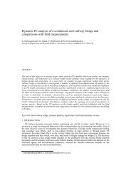
The wrought-iron bridge which is examined here was constructed in 1905 and has a single<br />
span <strong>of</strong> 9.6 m. The superstructure consists <strong>of</strong> three riveted main girders, interconnected with<br />
cross-girders and railbearers, which will be referred to as stringers for the remainder <strong>of</strong> the paper.<br />
The overall FE model and part <strong>of</strong> the mesh <strong>of</strong> the bridge are shown in Figure 2. The outer<br />
and the inner main girders are, respectively, 556x1120 mm and 668x1225 mm built-up sections,<br />
whereas cross-girders and stringers are 320x380 mm and 340x280 mm built-up sections, respectively.<br />
Flange and web thickness varies between 6.35-20.6 mm. All members are modeled using<br />
8-noded shell elements whereas the riveted connections are modeled using spring elements<br />
with variable stiffness. The bridge is considered to be simply supported, therefore, simple and<br />
roller supports are introduced to the main girders at their ends. The self-weight <strong>of</strong> the bridge and<br />
the superimposed dead load (ballast, rails, sleepers) are neglected since their effect on stress<br />
ranges is expected to be small for this bridge.<br />
The bridge is loaded with the BS 5400 (1980) Steel Train (No 1) shown in Figure 3, which is<br />
the heaviest <strong>of</strong> the BS 5400 trains. The train is traversed in steps <strong>of</strong> 1 m over one side <strong>of</strong> the<br />
bridge. No dynamic effects are taken into account since they have been found to be negligible in<br />
similar bridges (Åkesson 1994). The axle loads are applied directly to the top flange <strong>of</strong> the<br />
stringers since this has been found to be a more critical case when compared to the case <strong>of</strong> distributing<br />
the axle loads through the rail ties and ballast (Philbrick et al. 1995).<br />
The stiffness <strong>of</strong> the springs, which are used for modeling the riveted connections, is calculated<br />
based on the analytical model developed by Lee & Moon (2002). This model assumes that<br />
the connection angle is fixed at the positions <strong>of</strong> the rivets and the overall deformation <strong>of</strong> the<br />
connection is small. The elastic rotational stiffness <strong>of</strong> the connection is calculated as (Lee &<br />
Moon 2002)<br />
2EI<br />
⎛ g + g ⎞<br />
= (1)<br />
1 2 3<br />
K l<br />
3<br />
a<br />
g g 1 1 4g<br />
⎟<br />
2<br />
⎟<br />
⎜<br />
⎝ + ⎠<br />
where EI = bending stiffness <strong>of</strong> the angle segment per unit length; la = angle length; and<br />
g1, g2 = grip lengths on each angle leg. An angle length <strong>of</strong> 260 mm, angle thickness <strong>of</strong> 12.6 mm<br />
and grip values <strong>of</strong> 40 mm are used in Equation 1. Three cases are examined on the basis <strong>of</strong> assuming<br />
different connection rotational stiffnesses. The first case assumes fully fixed connections<br />
(infinite stiffness) and is modeled by tying the various members to each other. For the second<br />
case, the connections are assumed to possess a rotational stiffness K given by Equation 1. In<br />
this case, an effective angle length la corresponding to the full angle length is used assuming a<br />
high clamping force in the rivets. This rotational stiffness value is, then, transformed into a set<br />
<strong>of</strong> translation springs stiffnesses by assuming plane sections remain plane. A total <strong>of</strong> 18 springs<br />
are used for the cross-girder-to-main girder connections and a total <strong>of</strong> 12 springs are used for the<br />
stringer-to-cross-girder connections. In the third case, corresponding to a reduced clamping<br />
force, a lower effective angle length la (diameter <strong>of</strong> rivet head × number <strong>of</strong> rivets) is used (Lee<br />
& Moon 2002). A rivet diameter <strong>of</strong> 19 mm is considered. This results in a reduced stiffness <strong>of</strong><br />
K/40 for the cross-girder-to-main girder connections and K/13 for the stringer-to-cross-girder<br />
connections. The different stiffness values are due to the different angle lengths used.<br />
The damage caused by the passage <strong>of</strong> a single train (Fig. 3) is calculated by using the rainflow<br />
counting method (Downing & Socie 1982) and Miner’s Rule (Miner 1945). To this end,<br />
the BS 5400 (1980) two slope S-N curve is used. Thickness effects are not considered since the<br />
largest thickness <strong>of</strong> the bridge elements is marginally higher than 16 mm (BS 7608 1993). The<br />
connection details are classified either as Class B with the appropriate stress concentration fac-
tor (2.4) or Class D details according to BS 5400 (1980). These details are shown in Figure 4.<br />
Accordingly, two different fatigue damage estimates are obtained for each connection.<br />
The elastic finite element analysis is performed with the commercial FE-package ABAQUS<br />
version 6.3 (2002) using a Young’s Modulus value <strong>of</strong> 200 GPa. The bridge mesh consists <strong>of</strong><br />
29,400 elements with a total <strong>of</strong> 554,670 degrees <strong>of</strong> freedom. Typical analyses running times are<br />
approximately 12 hours on a SUN Enterprise 250 workstation with 2GB <strong>of</strong> RAM.<br />
Figure 1. Typical stringer-to-cross-girder connection (Yen et al. 1991).<br />
Figure 2. Model <strong>of</strong> the bridge and part <strong>of</strong> the mesh used.<br />
Figure 3. Axle loads and spacings <strong>of</strong> BS 5400 Steel Train No 1 (BS 5400 1980).
Figure 4. Classification <strong>of</strong> fatigue details according to BS 5400 (1980).<br />
3 RESULTS AND DISCUSSION<br />
The connections <strong>of</strong> the bridge are numbered as shown in Figure 2. In the notation used subsequently,<br />
the first number refers to the investigated connection, while the second connection<br />
number indicates the relevant direction. For example S5-S7 refers to the connection at location<br />
S5 in the direction <strong>of</strong> connection S7. Stress histories are obtained at a distance <strong>of</strong> 250 mm from<br />
the stringer-to-cross-girder interface and a distance <strong>of</strong> 300 mm from the cross-girder-to-main<br />
girder interface. At these distances, stress concentration effects, which are, within the context <strong>of</strong><br />
this global analysis rather spurious, are found to diminish considerably. The stresses during the<br />
entire stress histories were compressive near the top flange at that position and tensile near the<br />
bottom flange for most <strong>of</strong> the connections. A typical stress history is shown in Figure 5. It is<br />
clear that the stress history is axle dominated which was shown to be the case for short span railroad<br />
bridges with short member lengths (Dick & McCabe 1990). It can, also, be seen that stress<br />
cycles are repeated after the passage <strong>of</strong> the engine since the train consists <strong>of</strong> 15 similar wagons<br />
following the first one. Overall, stress ranges were found to vary between 10-30 MPa which is<br />
in agreement with field measurements on similar bridges (Åkesson 1994, Brühwiler 1995).<br />
Damage is calculated at the bottom <strong>of</strong> the connections near the member bottom flange since<br />
these parts are found to be in tension. The parts near the top flange, which are found to be in<br />
compression, are, for the purpose <strong>of</strong> fatigue damage evaluation, ignored.<br />
In the following sections, comparisons between the various connections <strong>of</strong> the bridge are<br />
made and the most critical ones are identified.<br />
Stress (MPa)<br />
30.000<br />
25.000<br />
20.000<br />
15.000<br />
10.000<br />
5.000<br />
0.000<br />
0 50 100 150 200 250<br />
-5.000<br />
Engine First car<br />
Time step<br />
Figure 5. Stress history near the bottom <strong>of</strong> the connection S5-S7.
3.1 Stringer-To-Cross-Girder Connection<br />
The damage results <strong>of</strong> the stringer-to-cross-girder connections are tabulated in Table 1 (Class B)<br />
and Table 2 (Class D). In these tables, connections are presented in order <strong>of</strong> decreasing damage,<br />
which results from the passage <strong>of</strong> a single train (Fig. 3). It is found that, for the fixed connection<br />
stiffness assumption, the outer connection damage (S1, S2, S9 and S10, Fig. 2) is substantially<br />
less than the inner connection damage. The critical connections that undergo the highest damage<br />
are identified to be the inner ones (S5, S6, S7 and S8, Fig. 2). For the seven most critical connections,<br />
damage ranking <strong>of</strong> the connections is not affected by the choice <strong>of</strong> the fatigue detail<br />
classification. In terms <strong>of</strong> the actual damage, the BS 5400 modified Class B detail is found to<br />
result in larger damage (with the difference varying between 12-57%) when compared with its<br />
Class D counterpart.<br />
By modeling the stringer-to-cross-girder connections using a stiffness value <strong>of</strong> K, the damage<br />
is found to decrease considerably between 4-76% as compared to the previous case (fully fixed).<br />
Overall, the decrease calculated by using Class B classification was found to be slightly higher<br />
than the one computed by assuming a Class D classification. The damage ranking is found to<br />
change with the outer connections corresponding to a higher rank as compared with the previous<br />
case <strong>of</strong> fixed stiffness. Nevertheless, the critical connections are again identified as being the<br />
middle stringer-to-cross-girder connections (S5 and S6, Fig. 2), albeit in a different direction.<br />
A further reduction <strong>of</strong> the stiffness <strong>of</strong> the connections to K/13, brought about by an assumed<br />
lower clamping force, results in a decreased damage that varies between 1-24% in relation to the<br />
previous case (K). The case <strong>of</strong> the Class B classification for the stringer-to-cross-girder connections<br />
results in a slightly higher decrease. The damage ranking is found to be similar to the ranking<br />
obtained by using throughout connection stiffness values <strong>of</strong> K and relatively unaffected by<br />
the assumed classification.<br />
3.2 Cross-Girder-To-Main Girder Connections<br />
The damage results <strong>of</strong> the cross-girder-to-main girder connections are tabulated in Tables 3<br />
(Class B) and 4 (Class D). Again, connections are presented in order <strong>of</strong> decreasing damage, calculated<br />
on the basis <strong>of</strong> the passage <strong>of</strong> a single train (Fig. 3). Connections which are in compression<br />
along their entire depth are indicated on the table and were assumed to have zero fatigue<br />
damage. For the case <strong>of</strong> fully fixed connections, the inner connections are found to be the three<br />
most critical ones (C2, C3, C4, Fig. 2). The damage in these connections was found to be considerably<br />
lower (as much as 100 times) than the damage calculated for the stringer-to-crossgirder<br />
connections. Overall, the damage ranking <strong>of</strong> the connections was not affected by the<br />
choice <strong>of</strong> the fatigue detail classification irrespective <strong>of</strong> the assumed connection stiffness.<br />
By modeling the cross-girder-to-main girder connections using a stiffness value <strong>of</strong> K, the<br />
damage is found to increase considerably by 88-100% compared to the previous case (fully<br />
fixed). The increase calculated by using Class B classification is found to be similar to the one<br />
computed by using a Class D classification. The damage ranking is found to change when<br />
changing the stiffness from fully fixed conditions to the value <strong>of</strong> K without, however, having<br />
any apparent pattern. In this case, C8, C9 and C3 become the three most critical fatigue details.<br />
A further reduction <strong>of</strong> the stiffness <strong>of</strong> the connections to K/40, due to an assumed lower<br />
clamping force, results in increased damage that varies between 3-24% compared to the previous<br />
case. The case <strong>of</strong> a Class B classification <strong>of</strong> the cross-girder-to-main girder connections results<br />
in a slightly higher damage increase. The damage ranking is found to be similar to the<br />
ranking <strong>of</strong> the previous case <strong>of</strong> using assumed connection stiffness values <strong>of</strong> K.<br />
3.3 Overall Comparisons Between The Connections<br />
It can be clearly seen, from the previous results, that the damage is much higher in the stringerto-cross-girder<br />
connections when compared with the cross-girder-to-main girder connections.<br />
For example, irrespective <strong>of</strong> classification <strong>of</strong> connection fixity, the most highly damaged crossgirder-to-main<br />
girder connection (C8, K/40, Class B) is almost three times less damaged than
the most damaged stringer-to-cross-girder connection (S5-S3, fixed, Class B). Connection C8<br />
would rank in Table 1 11 th for fixed, 7 th for K and 7 th for K/40. Similarly in Table 2, connection<br />
(C8, K/40, Class D) would rank 8 th for fixed, 8 th for K and 7 th for K/40. Therefore, it is justifiable<br />
to conclude that the stringer-to-cross-girder connections are overall more critical in terms<br />
<strong>of</strong> fatigue damage. This distinction can be made more clearly when assuming fully fixed connections,<br />
which although unrealistic, yield the highest damage and hence the most conservative<br />
results.<br />
Table 1. Class B stringer-to-cross-girder connection damage.<br />
Fixed K K/13<br />
Connection Damage Connection Damage Connection Damage<br />
S5-S3 2.58E-07 S5-S7 1.41E-07 S2 1.23E-07<br />
S6-S4 2.43E-07 S6-S8 1.28E-07 S5-S7 1.05E-07<br />
S8-S10 2.32E-07 S2 1.19E-07 S6-S8 9.75E-08<br />
S7-S9 2.22E-07 S8-S10 1.04E-07 S9 9.58E-08<br />
S5-S7 2.03E-07 S10 9.70E-08 S10 9.20E-08<br />
S6-S8 1.97E-07 S9 9.09E-08 S8-S10 9.03E-08<br />
S8-S6 9.40E-08 S7-S9 7.91E-08 S7-S9 6.71E-08<br />
S4-S6 8.56E-08 S7-S5 7.21E-08 S1 6.63E-08<br />
S3-S5 8.29E-08 S8-S6 6.77E-08 S7-S5 6.26E-08<br />
S7-S5 8.18E-08 S1 6.56E-08 S8-S6 6.10E-08<br />
S3-S1 4.99E-08 S5-S3 6.12E-08 S5-S3 4.69E-08<br />
S4-S2 4.92E-08 S6-S4 5.89E-08 S6-S4 4.67E-08<br />
S10 1.24E-08 S4-S6 4.30E-08 S4-S6 3.73E-08<br />
S2 1.01E-08 S3-S5 4.27E-08 S3-S5 3.43E-08<br />
S9 6.53E-09 S4-S2 1.72E-08 S4-S2 1.69E-08<br />
S1 4.64E-09 S3-S1 1.28E-08 S3-S1 1.22E-08<br />
Table 2. Class D stringer-to-cross-girder connection damage.<br />
Fixed K K/13<br />
Connection Damage Connection Damage Connection Damage<br />
S5-S3 1.11E-07 S5-S7 6.57E-08 S2 6.31E-08<br />
S6-S4 1.05E-07 S2 6.14E-08 S5-S7 5.16E-08<br />
S8-S10 1.02E-07 S6-S8 6.08E-08 S6-S8 4.87E-08<br />
S7-S9 9.82E-08 S8-S10 5.30E-08 S9 4.81E-08<br />
S5-S7 9.31E-08 S10 4.93E-08 S10 4.72E-08<br />
S6-S8 9.04E-08 S9 4.60E-08 S8-S10 4.72E-08<br />
S8-S6 4.62E-08 S7-S9 4.31E-08 S1 3.75E-08<br />
S7-S5 4.12E-08 S7-S5 3.96E-08 S7-S9 3.75E-08<br />
S4-S6 3.96E-08 S8-S6 3.76E-08 S7-S5 3.54E-08<br />
S3-S5 3.80E-08 S10 3.72E-08 S8-S6 3.46E-08<br />
S3-S1 2.97E-08 S5-S3 3.46E-08 S6-S4 2.79E-08<br />
S4-S2 2.93E-08 S6-S4 3.37E-08 S5-S3 2.79E-08<br />
S10 8.68E-09 S4-S6 2.60E-08 S4-S6 2.32E-08<br />
S2 7.86E-09 S3-S5 2.57E-08 S3-S5 2.15E-08<br />
S9 4.98E-09 S4-S2 1.19E-08 S4-S2 1.18E-08<br />
S1 4.07E-09 S3-S1 9.44E-09 S3-S1 9.07E-09
4 CONCLUSIONS<br />
A finite element analysis <strong>of</strong> a typical riveted railway bridge was carried out by traversing over<br />
the bridge the heaviest BS 5400 (1980) train. Damage in each connection was calculated using a<br />
two-slope S-N curve and Miner’s Rule. Comparisons between connections were made under an<br />
assumed two-class scheme (modified B and D). As expected, fatigue classification also alters<br />
the damage calculation.<br />
It was found that connection fixity affects considerably the stress histories and associated<br />
damage in the connections. However, overall, the fatigue ranking <strong>of</strong> the connections is not critically<br />
affected by the assumptions regarding fixity. The most critical connections, with only one<br />
track loaded, were identified as being the fully fixed stringer-to-cross-girder connections. More<br />
detailed investigation <strong>of</strong> these connections is currently under way.<br />
Table 3. Class B cross-girder-to-main girder damage.<br />
Fixed K K/40<br />
Connection Damage Connection Damage Connection Damage<br />
C4 3.19E-09 C8 6.88E-08 C8 8.01E-08<br />
C2 2.76E-09 C9 5.93E-08 C9 6.66E-08<br />
C3 2.68E-09 C3 5.00E-08 C3 6.62E-08<br />
C1 7.13E-10 C7 4.68E-08 C7 5.62E-08<br />
C7 5.64E-10 C4 4.09E-08 C4 5.41E-08<br />
C9 4.15E-10 C2 3.64E-08 C2 4.70E-08<br />
C8 1.26E-10 C5 2.41E-08 C5 2.50E-08<br />
C6 Compres. C6 1.51E-08 C10 1.93E-08<br />
C5 Compres. C10 1.28E-08 C1 1.61E-08<br />
C10 Compres. C1 1.01E-08 C6 1.26E-08<br />
Table 4. Class D cross-girder-to-main girder damage.<br />
Fixed K K/40<br />
Connection Damage Connection Damage Connection Damage<br />
C4 2.76E-09 C8 3.65E-08 C8 4.13E-08<br />
C2 2.43E-09 C9 3.22E-08 C9 3.54E-08<br />
C3 2.30E-09 C3 2.79E-08 C3 3.53E-08<br />
C1 8.58E-10 C7 2.68E-08 C7 3.09E-08<br />
C7 6.65E-10 C4 2.36E-08 C4 2.97E-08<br />
C9 5.14E-10 C2 2.16E-08 C2 2.66E-08<br />
C8 1.93E-10 C5 1.60E-08 C5 1.65E-08<br />
C6 Compres. C6 1.10E-08 C10 1.33E-08<br />
C5 Compres. C10 9.43E-09 C1 1.15E-08<br />
C10 Compres. C1 7.84E-09 C6 9.40E-09<br />
ACKNOWLEDGEMENTS<br />
The work described in this paper forms part <strong>of</strong> an ongoing project supported by EPSRC and<br />
Network Rail. The opinions expressed are those <strong>of</strong> the authors and do not necessarily represent<br />
those <strong>of</strong> the sponsors. We would like to thank Mr Brian Bell, Network Rail Project Officer, for<br />
valuable discussions and feedback on the paper.
REFERENCES<br />
ABAQUS. 2002. Standard User’s Manual Version 6.3. Hibbitt, Karlsson & Sorensen, Inc.<br />
Abouelmaaty, W. Maragakis, E. Itani, A. & Douglas, B. 1999. Fatigue Testing <strong>of</strong> Double-Angle Connections<br />
<strong>of</strong> Steel Railroad Bridges. Transportation <strong>Research</strong> Record 1688: 46-52. Washington: Transportation<br />
<strong>Research</strong> Board.<br />
Adamson, D. E. & Kulak, G.L. 1995. Fatigue Tests <strong>of</strong> Riveted Bridge Girders. Structural Engineering<br />
Report No 210. Department <strong>of</strong> Civil Engineering. <strong>University</strong> <strong>of</strong> Alberta. Edmonton. Canada.<br />
Åkesson, B. 1994. Fatigue Life <strong>of</strong> Riveted Railway Bridges. PhD Thesis. Publ. S 94:6. Department <strong>of</strong><br />
Structural Engineering. Chalmers <strong>University</strong> <strong>of</strong> Technology. Göteborg. Sweden.<br />
Al-Emrani, M. 1999. Stringer-to-Floor-Beam Connections in Riveted Railway Bridges. Publ. S 99:4.<br />
Chalmers <strong>University</strong> <strong>of</strong> Technology. Göteborg. Sweden.<br />
Al-Emrani, M. 2000. Two Fatigue-Related Problems in Riveted Railway Bridges. Licentiate Thesis. Department<br />
<strong>of</strong> Structural Engineering. Chalmers <strong>University</strong> <strong>of</strong> Technology. Göteborg. Sweden.<br />
Al-Emrani, M. 2002. Fatigue in Riveted Railway Bridges – A Study <strong>of</strong> the Fatigue Performance <strong>of</strong> Riveted<br />
Stringers and Stringer-to-Floor-Beam Connections. PhD Thesis. Department <strong>of</strong> Structural Engineering.<br />
Chalmers <strong>University</strong> <strong>of</strong> Technology. Göteborg. Sweden.<br />
Al-Emrani, M. & Kliger, R. 2003. FE Analysis <strong>of</strong> Stringer-to-Floor-Beam Connections in Riveted Railway<br />
Bridges. Journal <strong>of</strong> Constructional Steel <strong>Research</strong> 59(7): 803-818.<br />
Brühwiler, E. 1995. Measurements for Evaluating the Remaining Service Life <strong>of</strong> a Riveted Bridges. Proceedings<br />
<strong>of</strong> the IABSE Symposium, San Fransisco: Extending the Lifespan <strong>of</strong> Structures: 1023-1028.<br />
Zurich.<br />
BS 5400. 1980. Steel, Concrete and Composite Bridges: Part 10: Code <strong>of</strong> Practice for Fatigue. London:<br />
British Standards Institute.<br />
BS 7608. 1990. Code <strong>of</strong> Practice for Fatigue Design and Assessment <strong>of</strong> Steel Structures. London: British<br />
Standards Institute.<br />
Dick, S.M. & McCabe, S.L. 1990. Investigation <strong>of</strong> Fatigue Life Assessment <strong>of</strong> Railway Bridges. Proceedings<br />
<strong>of</strong> the 2 nd Workshop on Bridge Engineering <strong>Research</strong> in Progress: 59-62.<br />
Downing, S.D. & Socie, D.F. 1982. Simple Rainflow Counting Algorithms. International Journal <strong>of</strong> Fatigue<br />
4(1): 31-40.<br />
Fisher, J.W. 1984. Fatigue and Fracture in Steel Bridges: Case Studies. New York: John Wiley & Sons.<br />
Fisher, J.W. Yen, B.T. & Wang D. 1984. NCHRP Report No 302: Fatigue and Fracture Evaluation for<br />
Rating Riveted Bridges. Transportation <strong>Research</strong> Board. National <strong>Research</strong> Council. Washington D.C.<br />
Fisher, J.W. Yen, B.T. & Wang D. 1984. Fatigue Strength <strong>of</strong> Riveted Bridge Members. Journal <strong>of</strong> Structural<br />
Engineering 116(11): 2968-2981.<br />
Jones, J. Abouelmaaty, W. Maragakis, E. Douglas, B. & Itani, A. 1997. Theoretical and Experimental Fatigue<br />
Evaluation <strong>of</strong> a Riveted Double Angle Shear Connection in an <strong>Open</strong>-Deck Through-Plate Girder<br />
Railway Bridge. Proceedings <strong>of</strong> the US-Canada-Europe Workshop on Bridge Engineering: 17-24.<br />
Zurich.<br />
Lee, S.S. & Moon, T.S. 2002. Moment-Rotation Model <strong>of</strong> Semi-Rigid Connections with Angles. Engineering<br />
Structures 24(2): 227-237.<br />
Mang, F. & Bucak, O. 1990. Experimental and Theoretical Investigations <strong>of</strong> Existing Railway Bridges.<br />
Proceedings <strong>of</strong> the IABSE Workshop, Lausanne: Remaining Fatigue Life <strong>of</strong> Steel Structures: 59-70.<br />
Zurich.<br />
Mang, F. & Bucak, O. 1991. Remaining Fatigue Life <strong>of</strong> Old Steel Bridges – Theoretical and Experimental<br />
Investigations on Railway Bridges. International Symposium on Fatigue and Fracture in Steel and<br />
Concrete Structures; Madras, India: 971-991.<br />
Miner, M.A. 1945. Cumulative Damage in Fatigue. Journal <strong>of</strong> Applied Mechanics 12: 159-164.<br />
Out, J.M.M. Fisher, J.W. & Yen, B.T. 1984. Fatigue Strength <strong>of</strong> Weathered and Deteriorated Riveted<br />
Members. Transportation <strong>Research</strong> Record 950: 10-20. Washington: Transportation <strong>Research</strong> Board.<br />
Paasch, R.K. & DePiero, A.H. 1999. Fatigue Crack Modeling in Bridge Deck Connection Details. Final<br />
Report SPR 380. Oregon Department <strong>of</strong> Transportation.<br />
Philbrick, T.W. Zodo, G.W. & Schiff, S.D. 1995. Fatigue Assessment <strong>of</strong> Through Plate Girder Railway<br />
Bridges. Journal <strong>of</strong> Structural Engineering 121(11): 1613-1619.<br />
Roeder, C.W. MacRae, G.A. Kalogiros, A.Y. & Leland, A. 2001. Fatigue Cracking <strong>of</strong> Riveted, Coped,<br />
Stringer-To-Floorbeam Connections. <strong>Research</strong> Report WA-RD 494.1. Washington State Department <strong>of</strong><br />
Transportation.<br />
Wyly, L.T. & Scott, M.B. 1956. An Investigation <strong>of</strong> Fatigue Failures in Structural Members <strong>of</strong> Ore<br />
Bridges under Service Loadings. Proceedings <strong>of</strong> the American Railway Engineering Association 57:<br />
175-297.<br />
Yen, B.T. Zhou, Y. & Fisher, J.W. 1991. Fatigue Behaviour <strong>of</strong> Stringer-Floorbeam Connection. Proceedings<br />
<strong>of</strong> the 8 th Annual International Bridge Conference, Pittsburgh: 149-155.