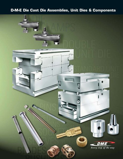
D-M-E Die Cast Die Assemblies, Unit Dies & Components
D-M-E Die Cast Die Assemblies, Unit Dies & Components
D-M-E Die Cast Die Assemblies, Unit Dies & Components

You also want an ePaper? Increase the reach of your titles
YUMPU automatically turns print PDFs into web optimized ePapers that Google loves.
D-M-E <strong>Die</strong> <strong>Cast</strong> <strong>Die</strong> <strong>Assemblies</strong>, <strong>Unit</strong> <strong>Die</strong>s & <strong>Components</strong>
2<br />
<strong>Die</strong> <strong>Cast</strong> | Table of Contents<br />
<strong>Die</strong> <strong>Cast</strong> <strong>Die</strong> <strong>Assemblies</strong><br />
Terms and Conditions of Sale. ............................ 4<br />
Sales and Ordering Information ........................... 5<br />
<strong>Die</strong> Makers and <strong>Die</strong> <strong>Cast</strong>ers .............................. 6<br />
<strong>Die</strong> <strong>Cast</strong> <strong>Die</strong> <strong>Assemblies</strong> . ................................ 7<br />
<strong>Die</strong> <strong>Cast</strong> <strong>Components</strong>.................................... 8<br />
Standard <strong>Unit</strong> <strong>Die</strong>s ...................................... 9-10<br />
Single <strong>Unit</strong> <strong>Die</strong> Holders . ................................. 11-12<br />
Double <strong>Unit</strong> <strong>Die</strong> Holders. ................................. 13-14<br />
Single Heavy-Duty <strong>Unit</strong> <strong>Die</strong> Holders . ...................... 15<br />
Double Heavy-Duty <strong>Unit</strong> <strong>Die</strong> Holders. ...................... 16<br />
Replacement <strong>Unit</strong>s . . . . . . . . . . . . . . . . . . . . . . . . . . . . . . . . . . . . . . 17<br />
Heavy-Duty Replacement <strong>Unit</strong>s . . . . . . . . . . . . . . . . . . . . . . . . . . . 18<br />
Master Layouts for <strong>Die</strong> <strong>Cast</strong> <strong>Die</strong> Designers ................. 19<br />
Sprue Spreaders........................................ 20<br />
Constant Area Sprue Spreaders and Sprue Bushings. ....... 21<br />
Constant Area Sprue Spreaders<br />
and Sprue Bushings (Small Size). ....................... 22<br />
Constant Area Sprue Spreaders<br />
and Sprue Bushings (Medium Size) . .................... 23<br />
Constant Area Sprue Spreaders<br />
and Sprue Bushings (Large Size) ....................... 24<br />
Runner Spreaders and Bushings .......................... 25<br />
Runner Spreaders and Bushings (Small Size) ............... 26<br />
Runner Spreaders and Bushings (Medium Size) ............ 27<br />
Runner Spreaders and Bushings (Large Size). .............. 28<br />
<strong>Die</strong> Clamps ............................................. 29<br />
<strong>Die</strong> <strong>Cast</strong> Chill Vents...................................... 29.1-29.4<br />
Slide Action <strong>Components</strong><br />
Angle Pins ............................................. 30<br />
Angle Pin Inserts........................................ 30.1<br />
Metric Angle Pins (Guide Pins). ........................... 31<br />
Cooling<br />
Brass Pressure Plugs.................................... 32<br />
Jiffy-Tite ® Connectors . .................................. 33<br />
Jiffy-Tite ® Plugs and Extension Plugs ...................... 34<br />
SV-Series Jiffy-Matic ® Connectors. ....................... 35-36<br />
Jiffy-Lok ® Connector Sockets. ............................ 37<br />
Jiffy-Tite ® Connector Seals,<br />
Seal Removal Tool Kit & Wrenches ..................... 38<br />
Jiffy-Tite ® and Jiffy-Matic ® Coolant Bridges. ............... 39<br />
Bubbler Tubes and Brass Diverting Plugs & Rods . .......... 40<br />
Jiffy-Tite ® Cascade Water Junctions . ..................... 41<br />
Cascade Water Junctions. ............................... 42<br />
Straight Brass Plug Baffles. .............................. 43<br />
Spiral Brass Plug Baffles. ................................ 44<br />
<strong>Die</strong> <strong>Components</strong> – Inch<br />
Guide Pins – Hardened and Precision Ground .............. 45<br />
Shoulder Guide Pins – Hardened<br />
and Precision Ground . ................................ 46<br />
Shoulder Bushings and Straight Bushings<br />
Hardened and Precision Ground ........................ 47<br />
Guide Pins and Shoulder Bushings<br />
2”, 2.5” and 3” Diameter . .............................. 48<br />
Self-Lubricating Bushings for Guide Pins. .................. 49<br />
Bronze-Plated Shoulder and Straight Bushings . ............ 50<br />
Guided Ejection Guide Pins. .............................. 51<br />
Guided Ejection Bushings . . . . . . . . . . . . . . . . . . . . . . . . . . . . . . . . 52<br />
Support Pillars and Stop Pins ............................. 53-54<br />
Guide Pins for Special <strong>Die</strong> Tooling Needs . ................. 55<br />
Special Guide Pins – Faxable Quote Form . ................. 56<br />
<strong>Die</strong> <strong>Components</strong> – Euro-Series<br />
Guide Pins (with Collar) . . . . . . . . . . . . . . . . . . . . . . . . . . . . . . . . . . 57-59<br />
Angle Pins ............................................. 60<br />
Guide Pins (without Collar) . .............................. 61-62<br />
Guide Pin Bushings (with Collar) and Self-Lube<br />
Guide Pin Bushings (with Collar) ........................ 63<br />
Guide Pin Bushings (without Collar) and Self-Lube<br />
Guide Pin Bushings (without Collar) ..................... 64<br />
Centering Bushing – Locating Sleeves ..................... 65<br />
Support Pillars.......................................... 66<br />
<strong>Die</strong> <strong>Cast</strong><br />
Table of Contents<br />
INCH Pins, Sleeves, Blades<br />
INCH Ejector Pins – H13 Nitrided – Straight ................ 67<br />
INCH Ejector Pins – H13 Nitrided – Shoulder ............... 68<br />
INCH High-Hardness Ejector Pins –<br />
H13 Nitrided – Straight ................................ 69<br />
Keyed Ejector Pins . ..................................... 70<br />
INCH Close Tolerance M-2<br />
Through-Hardened Ejector Pins. .......................... 71<br />
INCH Ejector Sleeves – Nitrided O.D. . ..................... 72<br />
INCH Ejector Sleeves – Nitrided O.D. & I.D.. ................ 73<br />
INCH Ejector Blades. .................................... 74-75<br />
INCH Core Pins – H13 – Standard Medium Hardness . ....... 76<br />
INCH Core Pins – High Hardness. ......................... 77<br />
INCH Return Pins ....................................... 78<br />
Custom Pins and Sleeves – Faxable Quote Form ............ 79<br />
DIN Pins, Sleeves, Blades<br />
DIN Ejector Pins – Nitrided ............................... 80<br />
DIN Ejector Pins – Hardened . ............................ 81<br />
DIN Shoulder Ejector Pins – Nitrided . ..................... 82<br />
DIN Shoulder Ejector Pins – Hardened. .................... 83<br />
DIN Ejector Sleeves – Nitrided. ........................... 84<br />
DIN Ejector Sleeves – Hardened . . . . . . . . . . . . . . . . . . . . . . . . . . 85<br />
DIN Ejector Blades – Nitrided. ............................ 86<br />
DIN Ejector Blades – Hardened ........................... 87<br />
DIN Core Pins – Hardened ............................... 88<br />
Special DIN Sleeves – Faxable Quote Form. ................ 89<br />
JIS Pins, Sleeves, Blades<br />
JIS Ejector Pins – Straight. ............................... 90<br />
JIS Ejector Sleeves. ..................................... 91<br />
JIS Ejector Blades ...................................... 92<br />
Quick Custom Pins – Faxable Quote Form . ................. 93<br />
D-M-E Ejector and Core Pin Diameters Table ............... 94<br />
<strong>Die</strong> Assembly<br />
Socket Head Cap Screws – Inch .......................... 95<br />
Socket Head Cap Screws – Metric ........................ 96<br />
Lock Washers (Spring Washers) – Metric. ................. 96<br />
Socket Head Stripper Bolts – Inch ........................ 97<br />
Keys and Key Kits – Inch ................................. 97<br />
Keys – Metric. .......................................... 98<br />
Shoulder Bolts (Stripper Bolts) – Metric ................... 98<br />
Flat Head Screws – Metric . . . . . . . . . . . . . . . . . . . . . . . . . . . . . . . 99<br />
Set Screws with Spring Loaded Ball<br />
Plunger (High Temperature) – Metric ................... 99<br />
Set Screws with Flat Point<br />
(Grub Screws) – Metric. ............................... 100<br />
Set Screws with Dog Point (Allen Head) – Metric . .......... 100<br />
Dowel Pins and Tubular Dowels – Inch . ................... 101<br />
Dowel Pins – Metric. .................................... 102<br />
Dowel Pins with Internal Thread (Pull Dowels). ............. 102<br />
Tubular Dowels; Washer/Tubular Dowel<br />
(Disk for Tubular Dowels) – Metric ...................... 103<br />
Stop Disk (for Ejector Plates) – Metric . .................... 103<br />
<strong>Die</strong> Springs Medium Duty (Blue) . ......................... 104<br />
<strong>Die</strong> Springs Medium Heavy Duty (Red). .................... 105<br />
<strong>Die</strong> Springs Heavy Duty (Gold) . . . . . . . . . . . . . . . . . . . . . . . . . . . . 106<br />
<strong>Die</strong> Springs Extra Heavy Duty (Green). ..................... 107<br />
Belleville Washers<br />
(Disc Springs) – Metric . . . . . . . . . . . . . . . . . . . . . . . . . . . . . . . . 108<br />
Hoist Rings – Inch. ...................................... 109-110<br />
Hoist Rings – Metric. .................................... 111<br />
U.S. 800-626-6653 ■ Canada 800-387-6600 ■ www.dme.net
Angle Pin Inserts. ..................................... 30.1<br />
Angle Pins ..........................................30, 60<br />
Angle Pins (Guide Pins) – Metric ..........................31<br />
Belleville Washers (Disc Springs) – Metric ................108<br />
Brass Pressure Plugs....................................32<br />
Bronze-Plated Shoulder and Straight Bushings .............50<br />
Bubbler Tubes and Brass Diverting Plugs & Rods ...........40<br />
Cascade Water Junctions................................42<br />
Centering Bushing – Locating Sleeves .....................65<br />
Constant Area Sprue Spreaders and Sprue Bushings........21<br />
Constant Area Sprue Spreaders and<br />
Sprue Bushings (Large Size)............................24<br />
Constant Area Sprue Spreaders and<br />
Sprue Bushings (Medium Size) .........................23<br />
Constant Area Sprue Spreaders<br />
and Sprue Bushings (Small Size) ........................22<br />
Core Pins – DIN Hardened ...............................88<br />
Core Pins – INCH – H13 – Standard Medium Hardness.......76<br />
Core Pins – INCH High Hardness..........................77<br />
Custom Pins and Sleeves – Faxable Quote Form ............79<br />
<strong>Die</strong> <strong>Cast</strong> Chill Vents. ...............................29.1-29.4<br />
<strong>Die</strong> <strong>Cast</strong> <strong>Die</strong> <strong>Assemblies</strong> ..................................7<br />
<strong>Die</strong> <strong>Cast</strong> <strong>Die</strong> <strong>Components</strong> .................................8<br />
<strong>Die</strong> Clamps .............................................29<br />
<strong>Die</strong> Makers and <strong>Die</strong> <strong>Cast</strong>ers ...............................6<br />
<strong>Die</strong> Springs – Extra Heavy Duty (Green) ...................107<br />
<strong>Die</strong> Springs – Heavy Duty (Gold) .........................106<br />
<strong>Die</strong> Springs – Medium Duty (Blue)........................104<br />
<strong>Die</strong> Springs – Medium Heavy Duty (Red) ..................105<br />
Double Heavy-Duty <strong>Unit</strong> <strong>Die</strong> Holders.......................16<br />
Double <strong>Unit</strong> <strong>Die</strong> Holders...............................13-14<br />
Dowel Pins – Metric....................................102<br />
Dowel Pins and Tubular Dowels – Inch ...................101<br />
Dowel Pins with Internal Thread (Pull Dowels).............102<br />
Ejector and Core Pin Diameters Table .....................94<br />
Ejector Blades – DIN Hardened ...........................87<br />
Ejector Blades – DIN Nitrided.............................86<br />
Ejector Blades – INCH . . . . . . . . . . . . . . . . . . . . . . . . . . . . . . . . 74-75<br />
Ejector Pins – DIN Hardened .............................81<br />
Ejector Pins – DIN Nitrided ...............................80<br />
Ejector Pins – INCH – H13 Nitrided – Shoulder ..............68<br />
Ejector Pins – INCH – H13 Nitrided – Straight ...............67<br />
Ejector Pins – INCH High-Hardness H13<br />
Nitrided – Straight.....................................69<br />
Ejector Pins – INCH Close Tolerance M2<br />
Through-Hardened ....................................71<br />
Ejector Sleeves – DIN Hardened ..........................85<br />
Ejector Sleeves – DIN Nitrided............................84<br />
Ejector Sleeves – INCH Nitrided O.D. ......................72<br />
Ejector Sleeves – INCH Nitrided O.D. & I.D..................73<br />
Extra Heavy Duty <strong>Die</strong> Springs (Green) ....................107<br />
Flat Head Screws – Metric . . . . . . . . . . . . . . . . . . . . . . . . . . . . . . . 99<br />
Guide Pin Bushings (with Collar) ..........................63<br />
Guide Pin Bushings (without Collar) .......................64<br />
Guide Pins – Hardened and Precision Ground ..............45<br />
Guide Pins (with Collar) . . . . . . . . . . . . . . . . . . . . . . . . . . . . . . . 57-59<br />
Guide Pins (without Collar) ............................61-62<br />
Guide Pins and Shoulder Bushings<br />
2”, 2.5” and 3” Diameter ...............................48<br />
Guide Pins for Special <strong>Die</strong> Tooling Needs ..................55<br />
Guided Ejection Bushings . . . . . . . . . . . . . . . . . . . . . . . . . . . . . . . . 52<br />
<strong>Die</strong> <strong>Cast</strong><br />
Index<br />
Guided Ejection Guide Pins...............................51<br />
Heavy Duty <strong>Die</strong> Springs (Gold) . . . . . . . . . . . . . . . . . . . . . . . . . . . 106<br />
Heavy Duty Replacement <strong>Unit</strong>s ...........................18<br />
Hoist Rings – Inch..................................109-110<br />
Hoist Rings – Metric....................................111<br />
Jiffy-Lok ® Connector Sockets.............................37<br />
Jiffy-Tite ® and Jiffy-Matic ® Coolant Bridges................39<br />
Jiffy-Tite ® Cascade Water Junctions ......................41<br />
Jiffy-Tite ® Connector Seals,<br />
Seal Removal Tool Kit & Wrenches......................38<br />
Jiffy-Tite ® Connectors ...................................33<br />
Jiffy-Tite ® Plugs and Extension Plugs ......................34<br />
JIS Ejector Blades ......................................92<br />
JIS Ejector Pins – Straight................................90<br />
JIS Ejector Sleeves......................................91<br />
Keyed Ejector Pins ......................................70<br />
Keys – Metric...........................................98<br />
Keys and Key Kits – Inch .................................97<br />
Lock Washers (Spring Washers) – Metric..................96<br />
Master Layouts for <strong>Die</strong> <strong>Cast</strong> <strong>Die</strong> Designers .................19<br />
Medium Duty <strong>Die</strong> Springs (Blue) .........................104<br />
Medium Heavy Duty <strong>Die</strong> Springs (Red)....................105<br />
Quick Custom Pins – Faxable Quote Form ..................93<br />
Replacement <strong>Unit</strong>s . . . . . . . . . . . . . . . . . . . . . . . . . . . . . . . . . . . . . . 17<br />
Return Pins – INCH......................................78<br />
Runner Spreaders and Bushings ..........................25<br />
Runner Spreaders and Bushings (Large Size)...............28<br />
Runner Spreaders and Bushings (Medium Size) ............27<br />
Runner Spreaders and Bushings (Small Size) ...............26<br />
Self-Lubricating Bushings for Guide Pins...................49<br />
Self-Lubricating Guide Pin Bushings (with Collar) ...........63<br />
Self-Lubricating Guide Pin Bushings (without Collar) ........64<br />
Set Screws with Dog Point (Allen Head) – Metric ..........100<br />
Set Screws with Flat Point (Grub Screws) – Metric.........100<br />
Set Screws with Spring Loaded Ball Plunger<br />
(High Temperature) – Metric ...........................99<br />
Shoulder Bolts (Stripper Bolts) – Metric ...................98<br />
Shoulder Bushings and Straight Bushings<br />
Hardened and Precision Ground ........................47<br />
Shoulder Ejector Pins – DIN Hardened.....................83<br />
Shoulder Ejector Pins – DIN Nitrided ......................82<br />
Shoulder Guide Pins – Hardened and Precision Ground. .....46<br />
Single Heavy Duty <strong>Unit</strong> <strong>Die</strong> Holders........................15<br />
Single <strong>Unit</strong> <strong>Die</strong> Holders ...............................11-12<br />
Socket Head Cap Screws – Inch ..........................95<br />
Socket Head Cap Screws – Metric ........................96<br />
Socket Head Stripper Bolts – Inch ........................97<br />
Special DIN Sleeves – Faxable Quote Form.................89<br />
Special Guide Pins – Faxable Quote Form ..................56<br />
Spiral Brass Plug Baffles.................................44<br />
Sprue Spreaders........................................20<br />
Stop Disk (for Ejector Plates) – Metric ....................103<br />
Straight Brass Plug Baffles...............................43<br />
Support Pillars..........................................66<br />
Support Pillars and Stop Pins ..........................53-54<br />
SV-Series Jiffy-Matic ® Connectors.....................35-36<br />
Tubular Dowels; Washer/Tubular Dowel<br />
(Disk for Tubular Dowels) – Metric .....................103<br />
<strong>Unit</strong> <strong>Die</strong>s .............................................9-10<br />
U.S. 800-626-6653 ■ Canada 800-387-6600 ■ www.dme.net<br />
3<br />
<strong>Die</strong> <strong>Cast</strong> | Index
4<br />
<strong>Die</strong> <strong>Cast</strong> | Terms and Conditions of Sales<br />
<strong>Die</strong> <strong>Cast</strong><br />
Terms and Conditions of Sale<br />
1. FOB POINT / PRICES: Products are sold F.O.B. point of origin.<br />
Any taxes are in addition to the prices and may be invoiced later.<br />
2. SHIPPING SCHEDULE: The shipping schedule is our current estimate<br />
of delivery dates and we agree to use reasonable efforts to comply<br />
with the schedule.<br />
3. WARRANTY:<br />
(a) Any D-M-E trademarked or tradenamed product or part thereof<br />
manufactured by or for us which, under normal operating conditions<br />
in the plant of the Buyer thereof, proves defective in material or<br />
workmanship, as determined by our inspection, within 12 months<br />
from the date of shipment will be replaced or repaired free of charge<br />
to Buyer.<br />
This warranty is contingent upon the following conditions: that we<br />
promptly receive notice of the defect; that Buyer establish that the<br />
product has been properly installed, maintained, and operated<br />
within the limits of related and normal usage as specified by us;<br />
and that, upon our request, Buyer will return to us at our expense<br />
the defective product or part thereof.<br />
(b) The terms of this warranty do not in any way extend to any<br />
product or part thereof which have a life, under normal usage,<br />
inherently shorter than 12 months.<br />
(c) The conditions of actual production in each end user’s plant<br />
vary considerably. Therefore, descriptions of the production or<br />
performance capabilities of any product or software materials<br />
are estimates only and are not warranted.<br />
4. EXCLUSIONS OF WARRANTIES: THE WARRANTIES TO REPAIR<br />
OR REPLACE DEFECTIVE PRODUCTS OR PARTS AS SET FORTH IN<br />
PARAGRAPH 3, AND ANY ADDITIONAL WARRANTY EXPRESSLY<br />
STATED TO BE A WARRANTY AND SET FORTH IN WRITING AS<br />
PART OF THESE TERMS HEREIN ARE IN LIEU OF ALL OTHER<br />
WARRANTIES, EXPRESS OR IMPLIED, INCLUDING BUT NOT<br />
LIMITED TO, ANY IMPLIED WARRANTY OF MERCHANTABILITY<br />
OR FITNESS FOR A PARTICULAR PURPOSE.<br />
5. LIMITATION OF REMEDIES AND LIABILITIES:<br />
UNDER NO CIRCUMSTANCES SHALL WE OR ANY AFFILIATE OF<br />
OURS HAVE ANY LIABILITY WHATSOEVER FOR INCIDENTAL OR<br />
CONSEQUENTIAL DAMAGES HOWSOEVER CAUSED OR ARISING<br />
(INCLUDING CONTRACT, NEGLIGENCE, STRICT LIABILITY OR<br />
OTHERWISE), such as, but not limited to, loss of profit or revenue;<br />
loss of use of the product, part thereof; cost of capital; cost of<br />
replacement equipment; or claims resulting from contracts between<br />
Buyer, its customers and/or suppliers. Unless expressly provided<br />
for herein, in no event shall we or any affiliate of ours assume<br />
responsibility or liability for (a) penalties, penalty clauses or<br />
liquidated damages clauses of any description, (b) certifications or<br />
(c) indemnification of Buyer or others for costs, damages or<br />
expenses arising out of or related to the product or part thereof.<br />
6. CANCELLATION: Unless otherwise agreed, Buyer may cancel all<br />
or any part of the order by written notice received by us before our<br />
completion of the order or applicable portion of the order. On receipt<br />
of such notice, all work on the order or part thereof canceled will be<br />
stopped as promptly as is reasonably possible. Buyer will then be<br />
invoiced for and will pay to us a cancellation charge. For completed<br />
items, the charge will be equal to their established prices. For items<br />
not completed, the charge will be equal to our full cost plus a<br />
premium in addition to a charge for any packing and storage<br />
and less a credit for the balance of the material as scrap.<br />
7. PAYMENT TERMS: Payment is due in accordance with any<br />
applicable progress, advance or other agreed upon payment<br />
schedule, or, if no such schedule has been agreed to, upon<br />
Acceptance as specified in Paragraph 8, but in no event later than<br />
30 days from the date of invoice. No cash discount is provided. If,<br />
in our judgment, Buyer’s financial condition changes, we may stop<br />
work until financial arrangements satisfactory to us are made.<br />
8. ACCEPTANCE OF PRODUCT: Each such product shall be deemed to<br />
be accepted within seven days after delivery of the product to the<br />
Buyer, unless we receive written notification of rejection for cause<br />
from Buyer within the seven day period.<br />
“Returned Goods”: No goods are returnable without prior approval,<br />
prepaid transportation and an issued RMA number. All items are<br />
subject to our inspection before credit will be allowed. Special mold<br />
bases or steel, items involving custom work, or items not shown<br />
in our catalog are considered non-returnable. A minimum service<br />
charge of 10% will be made on all returned goods.<br />
NO GOODS ARE RETURNABLE LATER THAN THIRTY DAYS AFTER<br />
RECEIPT OF MERCHANDISE.<br />
9. PATENT INDEMNITY: We shall defend any suit or proceeding<br />
brought against Buyer and pay all costs and damages awarded<br />
against Buyer provided that:<br />
(a) The suit or proceeding is based upon a claim that the product or<br />
part thereof is an infringement of any claim of a presently existing<br />
U.S. patent;<br />
(b) The claim of infringement is not based, directly or indirectly,<br />
upon (i) the manufacture, use, or sale of any product furnished by<br />
us which has been modified without our consent; or, (ii) the manufacture,<br />
use, or sale of any combination of a product furnished by us<br />
with products not furnished by us; or (iii) performance of a patented<br />
process using a product furnished by us or production thereby of a<br />
patented product; and,<br />
(c) We are notified promptly and given information and assistance<br />
(at our expense) and the authority to defend the suit or proceeding.<br />
We shall not be responsible hereunder for any settlement made<br />
without our written consent nor shall we be responsible for costs<br />
or expenses incurred without our written consent. If our product is<br />
adjudicated to be an infringement and its use in the U.S. by Buyer is<br />
enjoined, we shall, at our own expense, either:<br />
(i) procure for Buyer the right to continue using our product;<br />
(ii) replace it with a noninfringing product;<br />
(iii) modify it so it becomes noninfringing;<br />
(iv) remove the product or part thereof and refund Buyer’s net<br />
book value and transportation costs attributable to it.<br />
The foregoing states our entire liability with respect to any patent<br />
infringement by our products or any parts thereof. To the extent that<br />
our product or any part thereof is supplied according to specifications<br />
and designs furnished by Buyer, Buyer agrees to indemnify us<br />
in the manner and to the extent set forth above insofar as the terms<br />
thereof are appropriate.<br />
10. FORCE MAJEURE: We shall not be liable for any delay in performance<br />
or nonperformance which is due to war, fire, flood, acts of<br />
God, acts of third parties, acts of governmental authority or any<br />
agency or commission thereof, accident, breakdown of equipment,<br />
differences with employees or similar or dissimilar causes beyond<br />
our reasonable control, including but not limited to, those interfering<br />
with production, supply or transportation of products, raw materials<br />
or components or our ability to obtain, on terms we deem reasonable,<br />
material, labor, equipment or transportation.<br />
11. ACCEPTANCE OF ORDERS: Buyer agrees that all orders, including<br />
any arising from our Proposal, shall include these terms and conditions<br />
only, notwithstanding any different or additional terms that<br />
may be embodied in Buyer’s order. All orders are subject to our<br />
acceptance and we reserve the right to reject orders as, in our<br />
sole judgement, mandated by business conditions. We reserve the<br />
right to not proceed with any order until all necessary information<br />
is received from Buyer.<br />
12. MERGER CLAUSE: This Agreement entirely supersedes any prior<br />
oral representations, correspondence, proposal, quotation, or<br />
agreement. This writing constitutes the final and total expression<br />
of such agreement between the parties, and it is a complete and<br />
exclusive statement of the terms of that agreement.<br />
13. ASSIGNMENT: Neither party may assign this Agreement without<br />
the written consent of the other party, except that we may assign<br />
this Agreement to a third party that acquires substantially all of<br />
our assets or we may assign the flow of funds arising out of<br />
this Agreement.<br />
14. GOVERNING LAW: This Agreement shall be governed by and<br />
construed in accordance with the laws of the State of Michigan.<br />
U.S. 800-626-6653 ■ Canada 800-387-6600 ■ www.dme.net
U.S.A.<br />
<strong>Die</strong> <strong>Cast</strong><br />
Sales and Ordering Information<br />
TERMS AND CONDITIONS OF SALE: See previous page.<br />
PHONE ORDERS – TOLL FREE: 800-626-6653. D-M-E’s Customer Service Dept. operates Monday through Friday from<br />
8 a.m. to 8 p.m. E.S.T. Calls can be made from anywhere in the continental U.S. and Puerto Rico (Puerto Rico: use “137” prefix<br />
instead of “1”). Our Customer Service Representatives will be happy to answer your questions on D-M-E products or services,<br />
provide on-the-spot feedback on product availability and shipping details, or take any messages you wish relayed to your local<br />
D-M-E sales, manufacturing or technical service representatives.<br />
MAIL ORDERS: If you prefer to order by mail, please address your order to:<br />
■ D-M-E Company, 29111 Stephenson Highway, Madison Heights, Michigan 48071-2330<br />
ATTN: Customer Service Dept.<br />
FAX: You may fax your order to:<br />
■ D-M-E Customer Service<br />
248-398-6174 • 888-808-4363<br />
CHECKS OR MONEY ORDERS: When paying invoices by check or money order, please make payable to D-M-E Company.<br />
Include remittance copy of invoice and mail to:<br />
■ D-M-E Company, Department Lock Box 78242, P.O. Box 78000, Detroit, Michigan 48278-0242<br />
WALK-IN ORDERS, PICK-UPS AND RETURNS: If desired, ordered products in stock at your nearest D-M-E Service Center<br />
can be picked up rather than shipped. Walk-in orders at Service Center locations can also be processed while you wait.<br />
Products being returned for repair or exchange should be processed through Customer Service prior to being returned.<br />
SPECIAL MACHINING SERVICES: Prints for quotation on special machining work can be sent by EDI to dme_cad@dme.net<br />
or mailed to the Estimating Department of the D-M-E manufacturing location nearest you. Call our toll-free number if desired<br />
to clarify location which serves your area.<br />
Estimating locations are:<br />
■ 70 East Hillis Street, Youngwood, Pa 15697, FAX: 724-925-2424<br />
■ 1117 Fairplains Street, Greenville, MI 48338, Tel. 616-754-4601, FAX: 616-225-3924<br />
■ 3275 Deziel Drive, Windsor, Ont N8W 5A5, Tel. 519-948-5001, FAX: 519-948-4652<br />
■ 464-466 Windy Point Drive, Glendale Heights, IL 60139, Tel. 630-469-4280, FAX: 630-469-4740 (estimating only)<br />
Please add “D-M-E Company” and “Attn: Estimating Dept.” to above addresses when mailing prints. To obtain prices and<br />
delivery on special mold base orders or to check status of special work in progress please contact Customer Service.<br />
CANADA<br />
TERMS AND CONDITIONS OF SALE: See previous page.<br />
PHONE ORDERS: Contact our Mississauga, Ontario office at 800-387-6600, FAX: 800-461-9965.<br />
MAIL ORDERS: Send to: D-M-E of Canada, Ltd., 6210 Northwest Drive, Mississauga, Ontario L4V 1J6.<br />
CHECK OR MONEY ORDERS: Make payable to D-M-E of Canada, Ltd. Include remittance copy of invoice and mail to<br />
Mississauga address above.<br />
WALK-IN ORDERS, PICK-UPS, RETURNS, AND SPECIAL MACHINING: Contact our Mississauga office.<br />
U.S. 800-626-6653 ■ Canada 800-387-6600 ■ www.dme.net<br />
5<br />
<strong>Die</strong> <strong>Cast</strong> | Sales and Ordering Information
6<br />
<strong>Die</strong> <strong>Cast</strong> | For <strong>Die</strong> Makers and <strong>Die</strong> <strong>Cast</strong>ers<br />
DIE BLOCKS,<br />
PLATES AND COMPONENTS<br />
DIE CLAMPS<br />
<strong>Die</strong> <strong>Cast</strong><br />
For <strong>Die</strong> Makers and <strong>Die</strong> <strong>Cast</strong>ers<br />
STANDARD<br />
UNIT DIES<br />
SPRUE SPREADERS AND BUSHINGS<br />
Three Ways to Increase Your Productivity<br />
1. USE D-M-E STANDARD "A" OR "B" SERIES MOLD BASES.<br />
With the appropriate sprue spreader and bushing installed,<br />
or a shot-sleeve hole bored to your specifications, D-M-E<br />
Standard "A" or "B" Series Bases are readily adapted for zinc<br />
and aluminum die casting. See page 7.<br />
2. USE D-M-E STANDARD DIE BLOCKS, PLATES AND OTHER<br />
COMPONENTS. With D-M-E's wide range of plates, die<br />
blocks, retainer sets, ejector pins and other die components<br />
you can design a complete die buildup to suit your specific<br />
needs and still retain the full benefits of D-M-E quality,<br />
standardization and service. See page 8.<br />
3. USE D-M-E STANDARD UNIT DIES. For both long and short<br />
runs, for zinc or aluminum D-M-E offers both single and<br />
double unit dies in a variety of sizes. Replacement units<br />
are available in D-M-E No. 2, No. 3 and No. 5 Steel.<br />
See pages 10-19.<br />
<strong>Unit</strong> <strong>Die</strong> Replacement Parts .............................................. page 19<br />
Replacement Sprue Spreaders (previous style) ................ page 20<br />
Sprue and Runner Spreaders and<br />
Bushings (for Zinc) ....................................................pages 20-28<br />
<strong>Die</strong> Clamps ......................................................................... page 29<br />
Information available on<br />
D-M-E Standard <strong>Unit</strong> <strong>Die</strong> Holders and Replacement <strong>Unit</strong>s<br />
To assist designers in saving time on laying out cavities and cores<br />
within D-M-E Standard <strong>Unit</strong> <strong>Die</strong>s, CAD Data can be downloaded<br />
from www.dme.net. The general dimensions of D-M-E’s complete<br />
line of Standard <strong>Unit</strong> <strong>Die</strong>s for zinc and aluminum are shown on<br />
page 19.<br />
U.S. 800-626-6653 ■ Canada 800-387-6600 ■ www.dme.net
D-M-E Standard "A" Series Mold Base<br />
with D-M-E Standard Water-cooled<br />
Sprue Spreader and Bushing installed<br />
for zinc die casting.<br />
D-M-E Standard "B" Series Mold Base with a<br />
shot-sleeve hole for aluminum die casting.<br />
<strong>Die</strong> <strong>Cast</strong><br />
<strong>Die</strong> <strong>Cast</strong> <strong>Die</strong> <strong>Assemblies</strong><br />
For Zinc and Aluminum <strong>Die</strong> <strong>Cast</strong>ing<br />
The economy of using standard mold assemblies for zinc and<br />
aluminum die casting has been well established over the years.<br />
Standard "A" and "B" Series Mold Bases are both widely used.<br />
For zinc die casting, a D-M-E Standard Water-cooled Sprue<br />
Spreader and Bushing are installed in place of the sprue bushing<br />
and sprue puller pin used in plastics molds. For aluminum, a<br />
shot-sleeve hole is bored to customer specifications.<br />
ALUMINUM DIE CAST DIES<br />
When ordering, please specify:<br />
1. Item Number of "A" or "B" Series Mold Base.<br />
2. No. 2 or No. 3 Steel (No. 5 Steel available on special order).<br />
Provide a dimensioned drawing with diameter and location of shot-sleeve<br />
hole. Prices will be quoted per your drawing.<br />
ZINC DIE CAST DIES<br />
When ordering, please specify:<br />
1. Item Number of "A" or "B" Series Mold Base.<br />
2. No. 2 or No. 3 Steel (No. 5 Steel available on special order).<br />
3. Item numbers of Spreader and Bushing required.<br />
4. If Spreader location is off-center, please supply a<br />
dimensioned drawing.<br />
See pages 21-28 for Spreaders and Bushings. Installation costs for<br />
Spreader and Bushing will be quoted per your drawing or specifications.<br />
FOR ZINC OR ALUMINUM DIES<br />
Prices can also be quoted per your drawing for the following<br />
additional work:<br />
■ cavity and core insert pockets<br />
■ core slide pockets<br />
■ shot plugs (furnish and install)<br />
■ runners and kicker pads<br />
■ knock-out holes<br />
■ ejector pin installation<br />
■ pipe clearance holes<br />
■ water lines and eye bolt holes<br />
■ special clamp slots<br />
U.S. 800-626-6653 ■ Canada 800-387-6600 ■ www.dme.net<br />
7<br />
<strong>Die</strong> <strong>Cast</strong> | <strong>Die</strong> <strong>Cast</strong> <strong>Die</strong> <strong>Assemblies</strong>
8<br />
<strong>Die</strong> <strong>Cast</strong> | <strong>Die</strong> <strong>Cast</strong> <strong>Die</strong> <strong>Components</strong><br />
CAVITY RETAINER SETS<br />
PAGES 11-18<br />
EJECTOR HOUSINGS<br />
PAGES 11-14<br />
MISCELLANEOUS PLATES<br />
SPREADERS AND BUSHINGS<br />
PAGES 20-28<br />
EJECTOR PINS, CORE PINS AND SLEEVES<br />
PAGES 67-73, 76-77, 80-85, 88<br />
<strong>Die</strong> <strong>Cast</strong><br />
<strong>Die</strong> <strong>Cast</strong> <strong>Die</strong> <strong>Components</strong><br />
In addition to the use of "A" and "B" Series Mold Bases for die casting as<br />
outlined on the previous page, die cast die assemblies can be constructed<br />
using D-M-E Standard <strong>Components</strong>. The drawing below illustrates a<br />
"two-plate" die cast die designe d entirely with standard components.<br />
Complete specifications and prices for the components can be found on<br />
the pages listed below.<br />
CAVITY RETAINER SET<br />
EJECTOR PIN<br />
SPRUE BUSHING SPRUE SPREADER<br />
EJECTOR PLATE<br />
EJECTOR HOUSING EJECTOR RETAINER PLATE<br />
ADDITIONAL DIE CAST DIE COMPONENTS FROM D-M-E<br />
Cascade Water Junctions ..............................................................41-42<br />
Cooling Items .................................................................................32-44<br />
Core Pins ..................................................................................76-77, 88<br />
<strong>Die</strong> Clamps .......................................................................................... 29<br />
<strong>Die</strong> Springs .................................................................................104-107<br />
Dowel Pins (solid and tubular) ...................................................101-103<br />
Ejector Pins .................................................................. 67-71, 80-83, 90<br />
Ejector Sleeves ............................................................ 72-73, 84-85, 91<br />
Ejector Blades .............................................................. 74-75, 86-87, 92<br />
Guided Ejection System .................................................................51-52<br />
Guide Pins and Bushings ................................................... 45-50, 55-65<br />
Hoist Rings .................................................................................109-111<br />
Jiffy-Tite and Jiffy-Matic Connectors ...........................................33-37<br />
Socket Head Cap Screws ..............................................................95-96<br />
Support Pillars and Stop Pins ..................................................53-54, 66<br />
U.S. 800-626-6653 ■ Canada 800-387-6600 ■ www.dme.net
<strong>Die</strong> <strong>Cast</strong><br />
Standard <strong>Unit</strong> <strong>Die</strong>s<br />
For Zinc and Aluminum <strong>Die</strong> <strong>Cast</strong>ing<br />
How long does it take to remove a die from a press and<br />
replace it (die changeover)? “For small dies,” die casters say,<br />
“it can take one and a half to two hours. For large dies…two<br />
days, three days, sometimes four days.” Downtime like this is<br />
unacceptable for die casters. That's why so many of them are<br />
now investing in D-M-E Standard <strong>Unit</strong> <strong>Die</strong> Holders for both<br />
long and short run zinc and aluminum die casting.<br />
20-MINUTE DIE CHANGEOVERS<br />
D-M-E Standard <strong>Unit</strong> <strong>Die</strong> Holders and Replacement <strong>Unit</strong>s<br />
are “made for each other.” They’re designed and ground<br />
to such close tolerances that die casters can remove<br />
Replacement <strong>Unit</strong>s from the Holders and put new ones in<br />
within 20 minutes or less. This cuts downtime and enables<br />
a die caster to increase productivity and profitability on<br />
both long- and short-run jobs.<br />
FOUR TYPES OF HOLDERS<br />
You can get four types of Standard <strong>Unit</strong> <strong>Die</strong> Holders from<br />
D-M-E: Single <strong>Unit</strong>; Double <strong>Unit</strong>; Single Heavy-Duty <strong>Unit</strong>;<br />
Double Heavy-Duty <strong>Unit</strong>. They are precision engineered<br />
and constructed of high quality die steels to withstand the<br />
increasingly higher pressures and injection speeds of today’s<br />
die casting machines.<br />
STANDARD REPLACEMENT UNITS<br />
D-M-E Standard and Standard Heavy-Duty Replacement <strong>Unit</strong>s are precision made and completely interchangeable when used<br />
with their matching Standard and Standard Heavy-Duty <strong>Unit</strong> <strong>Die</strong> Holders. Replacement <strong>Unit</strong>s are available in D-M-E No. 2,<br />
No. 3, or No. 5 Steel. The more popular sizes are carried in stock for immediate delivery.<br />
D-M-E NO. 2 STEEL<br />
An AISI 4130 type steel. It is<br />
pre-heat treated to approximately<br />
302 Bhn (32 HRC) to withstand the<br />
peening effects of flash. Its highstrength<br />
steel is ideal for applications<br />
where cavity inserts will be used<br />
in the Replacement <strong>Unit</strong>s.<br />
D-M-E NO. 3 STEEL<br />
An exceptionally clean P-20 AISI<br />
4130 (modified) type cavity steel,<br />
pre-heat treated to 277-321 Bhn<br />
(28-35 HRC). It provides high<br />
hardness, good machinability,<br />
and exceptional polishability.<br />
It also provides excellent tool life,<br />
especially for zinc die cast dies.<br />
REPLACEMENT UNITS IN ANY STEEL OR HARDNESS<br />
REQUIRED ARE AVAILABLE ON SPECIAL ORDER<br />
D-M-E NO. 5 STEEL<br />
A thermal-shock resistant, hotwork die<br />
steel (H-13 type). Supplied fully annealed,<br />
approx. 200 Bhn (93 HRB), for easy<br />
machinability, it can be subsequently<br />
heat treated to the desired hardness<br />
with a minimum of deformation. Ideal for<br />
aluminum and most long run die casting<br />
applications. D-M-E No. 5 Steel meets<br />
or exceeds the acceptance criteria<br />
established by the NADCA as<br />
detailed in Technical Digest<br />
Number 01-80-01 D.<br />
U.S. 800-626-6653 ■ Canada 800-387-6600 ■ www.dme.net<br />
9<br />
<strong>Die</strong> <strong>Cast</strong> | Standard <strong>Unit</strong> <strong>Die</strong>s
10<br />
<strong>Die</strong> <strong>Cast</strong> | Standard <strong>Unit</strong> <strong>Die</strong>s<br />
D-M-E STANDARD SINGLE UNIT DIE HOLDER<br />
WITH REPLACEMENT UNIT<br />
D-M-E STANDARD DOUBLE UNIT DIE HOLDER<br />
WITH REPLACEMENT UNITS<br />
D-M-E STANDARD HEAVY-DUTY DOUBLE UNIT DIE<br />
HOLDER WITH REPLACEMENT UNITS<br />
<strong>Die</strong> <strong>Cast</strong><br />
Standard <strong>Unit</strong> <strong>Die</strong>s<br />
For Zinc and Aluminum <strong>Die</strong> <strong>Cast</strong>ing<br />
Pre-Engineered Design Features<br />
■ Maximum Cavity Area for Greater Range of Jobs<br />
Three sides of Replacement <strong>Unit</strong>s are open for<br />
placement of core slides or water lines<br />
■ Rigid Center Section for Longer <strong>Die</strong> Life<br />
Center Section is made from D-M-E No. 5 Steel (H-13<br />
type) heat treated to 42-46 Rockwell C. Upper and<br />
lower halves are recessed for added rigidity<br />
■ Accurate Alignment for Minimum Wear<br />
Six Leader Pins and six Return Pins (four of each in<br />
Single <strong>Unit</strong> Holders) provide better alignment and<br />
permit uniform control of Ejector Plate<br />
■ Positive Locking of Interchangeable <strong>Unit</strong>s<br />
Precision made center section has solid horizontal and<br />
vertical keys for positive locking of Replacement <strong>Unit</strong>s.<br />
Pry-bar slots facilitate removal of units<br />
■ Wedge Clamps and Solid Steel Wedge Locks<br />
"Beef Up" Safety<br />
To "beef up" safety and speed die changeovers, D-M-E<br />
Single and Double <strong>Unit</strong> <strong>Die</strong> Holders are equipped with<br />
wedge clamps with heavy-duty socket screws. D-M-E<br />
Single and Double Heavy-Duty <strong>Unit</strong> <strong>Die</strong> Holders have<br />
solid steel wedge locks for the same purposes<br />
On the smaller D-M-E Single and Double <strong>Unit</strong> <strong>Die</strong><br />
Holders a specially developed "space-saver" design<br />
with heavy-duty socket screws makes equally fast<br />
die changeovers possible<br />
■ Designed for Zinc or Aluminum Applications<br />
Available with Water-cooled Sprue Spreader and<br />
Bushing installed for zinc or with shot-sleeve hole<br />
bored to specifications for aluminum die casting<br />
U.S. 800-626-6653 ■ Canada 800-387-6600 ■ www.dme.net
For Zinc and Aluminum <strong>Die</strong> <strong>Cast</strong>ing<br />
<strong>Die</strong> <strong>Cast</strong><br />
Single <strong>Unit</strong> <strong>Die</strong> Holders<br />
Designed for smaller die casting machines (50-150 ton)<br />
12.875<br />
1.875<br />
2.875<br />
2.875<br />
5.25<br />
4.375<br />
1.3125<br />
U.S. Pat. No. 2956321<br />
Can. Pat. No. 620895<br />
DCS-108 SINGLE UNIT DIE HOLDERS<br />
CENTER SECTION<br />
No. 5 Steel (H-13 type), heat treated to 42-46 Rockwell C<br />
TOP CLAMPING PLATE<br />
No. 2 Steel (AISI 4130 type), pre-heat treated to 271-321 Bhn<br />
EJECTOR HOUSING<br />
High Carbon Steel, pre-heat treated to approx. 300 Bhn<br />
FOR ZINC<br />
Spreader and Bushing specified will be installed. Cost of Spreader,<br />
Bushing and installation included in List Prices.<br />
FOR ALUMINUM<br />
Straight shot sleeve hole bored to your specifications included in<br />
List Prices. (Please supply a dimensioned drawing.)<br />
13.875<br />
VIEW Y-Y 5.875<br />
U.S. 800-626-6653 ■ Canada 800-387-6600 ■ www.dme.net<br />
9.875<br />
Y Y<br />
ITEM NUMBERS SHOWN ARE FOR UNIT HOLDERS ONLY AND DO NOT<br />
INCLUDE THE REPLACEMENT UNITS, SEE PAGE 17.<br />
FOR OTHER REPLACEMENT PARTS, SEE PAGE 19.<br />
ITEM<br />
NUMBER<br />
DCS-108-A<br />
DCS-108-Z<br />
NET<br />
WEIGHT<br />
REPLACEMENT<br />
UNIT SIZE<br />
300 8.000 x 9.875<br />
WHEN ORDERING FROM PAGES 11-12, PLEASE SPECIFY:<br />
1. Quantity and Item Number<br />
2. Bushing and Spreader Item Numbers (for Zinc) See pages 20-28<br />
3. Shot-Sleeve Diameter and Location (for Aluminum)<br />
4. Method of Shipment<br />
11<br />
<strong>Die</strong> <strong>Cast</strong> | Single <strong>Unit</strong> <strong>Die</strong> Holders
12<br />
<strong>Die</strong> <strong>Cast</strong> | Single <strong>Unit</strong> <strong>Die</strong> Holders<br />
For Zinc and Aluminum <strong>Die</strong> <strong>Cast</strong>ing<br />
L<br />
VIEW Y-Y<br />
<strong>Die</strong> <strong>Cast</strong><br />
Single <strong>Unit</strong> <strong>Die</strong> Holders<br />
Y Y<br />
X<br />
DCS-1012, DCS-1215 and DCS-1518 SINGLE UNIT DIE HOLDERS<br />
CENTER SECTION<br />
No. 5 Steel (H-13 type), pre-heat treated to approx. 200 Bhn (94 HRB)<br />
TOP CLAMPING PLATE<br />
No. 2 Steel (AISI 4130 type), pre-heat treated to 369-321 Bhn (28-34 HRC)<br />
EJECTOR HOUSING<br />
1012 and 1215: High Carbon Steel, pre-heat treated to approx. 300 Bhn (32 HRC)<br />
1518: No. 2 Steel (AISI 4130 type), pre-heat treated to 271-321 Bhn (28-34 HRC)<br />
FOR ZINC<br />
Spreader and Bushing specified will be installed. Cost of Spreader, Bushing and installation included in List Prices.<br />
FOR ALUMINUM<br />
Straight shot sleeve hole bored to your specifications included in List Prices. (Please supply a dimensioned drawing.)<br />
ITEM<br />
NUMBER<br />
DCS-1012-A<br />
DCS-1012-Z<br />
DCS-1215-A<br />
DCS-1215-Z<br />
DCS-1518-A<br />
DCS-1518-Z<br />
W L H N C S X A B<br />
ITEM NUMBERS SHOWN ARE FOR UNIT HOLDERS ONLY AND DO NOT INCLUDE THE REPLACEMENT UNITS, SEE PAGE 17.<br />
FOR OTHER REPLACEMENT PARTS, SEE PAGE 19.<br />
W<br />
U.S. 800-626-6653 ■ Canada 800-387-6600 ■ www.dme.net<br />
H<br />
2.375<br />
A<br />
B<br />
N<br />
NET<br />
WEIGHT<br />
C<br />
U.S. Pat. No. 2956321<br />
Can. Pat. No. 620895<br />
S<br />
REPLACEMENT<br />
UNIT SIZE<br />
11.875 17.875 15.125 6.000 5.125 2.0625 8.000 3.375 3.375 535 9.875 x 11.875<br />
14.875 21.000 16.250 6.125 5.250 2.0625 9.125 3.875 3.875 835 11.875 x 14.875<br />
17.875 24.000 18.125 7.000 5.625 2.3125 9.125 4.375 4.375 1296 14.875 x 17.875
<strong>Die</strong> <strong>Cast</strong><br />
Double <strong>Unit</strong> <strong>Die</strong> Holders<br />
For Zinc and Aluminum <strong>Die</strong> <strong>Cast</strong>ing<br />
Designed for smaller die casting machines (50-150 ton)<br />
12.875<br />
1.875<br />
2.875<br />
2.875<br />
5.250<br />
4.375<br />
6.875<br />
1.3125<br />
U.S. Pat. No. 2956321<br />
Can. Pat. No. 620895<br />
DC -108 DOUBLE UNIT DIE HOLDERS<br />
CENTER SECTION<br />
No. 5 Steel (H-13 type), heat treated to 42-46 Rockwell C<br />
TOP CLAMPING PLATE<br />
No. 2 Steel (AISI 4130 type), pre-heat treated to 271-321 Bhn<br />
EJECTOR HOUSING<br />
High Carbon Steel, pre-heat treated to approx. 300 Bhn<br />
FOR ZINC<br />
Spreader and Bushing specified will be installed. Cost of Spreader,<br />
Bushing and installation included in List Prices.<br />
FOR ALUMINUM<br />
Straight shot sleeve hole bored to your specifications included in<br />
List Prices. (Please supply a dimensioned drawing.)<br />
ITEM NUMBERS SHOWN ARE FOR UNIT HOLDERS ONLY AND<br />
DO NOT INCLUDE THE REPLACEMENT UNITS, SEE PAGE 17.<br />
FOR OTHER REPLACEMENT PARTS, SEE PAGE 19.<br />
U.S. 800-626-6653 ■ Canada 800-387-6600 ■ www.dme.net<br />
19.750<br />
3.750<br />
VIEW Y-Y<br />
8<br />
9.875<br />
Y Y<br />
ITEM<br />
NUMBER<br />
DC-108-A<br />
DC-108-Z<br />
NET<br />
WEIGHT<br />
REPLACEMENT<br />
UNIT SIZE<br />
340 8.000 x 9.875<br />
WHEN ORDERING FROM PAGES 13-14, PLEASE SPECIFY:<br />
1. Quantity and Item Number<br />
2. Bushing and Spreader Item Numbers (for Zinc) See pages 20-28<br />
3. Shot-Sleeve Diameter and Location (for Aluminum)<br />
4. Method of Shipment<br />
13<br />
<strong>Die</strong> <strong>Cast</strong> | Double <strong>Unit</strong> <strong>Die</strong> Holders
14<br />
<strong>Die</strong> <strong>Cast</strong> | Double <strong>Unit</strong> <strong>Die</strong> Holders<br />
For Zinc and Aluminum <strong>Die</strong> <strong>Cast</strong>ing<br />
<strong>Die</strong> <strong>Cast</strong><br />
Double <strong>Unit</strong> <strong>Die</strong> Holders<br />
X<br />
L<br />
VIEW Y-Y<br />
Y Y H<br />
DC-1012, DC-1215 and DC-1518 DOUBLE UNIT DIE HOLDERS<br />
CENTER SECTION<br />
No. 5 Steel (H-13 type), heat treated to 42-46 Rockwell C<br />
TOP CLAMPING PLATE<br />
No. 2 Steel (AISI 4130 type), pre-heat treated to 269-321 Bhn<br />
EJECTOR HOUSING<br />
1012 & 1215: High Carbon Steel, pre-heat treated to approx. 300 Bhn<br />
1518: No. 2 Steel (AISI 4130 type), pre-heat treated to 269-321 Bhn<br />
FOR ZINC<br />
Spreader and Bushing specified will be installed. Cost of Spreader, Bushing and installation included in List Prices.<br />
FOR ALUMINUM<br />
Straight shot sleeve hole bored to your specifications included in List Prices. (Please supply a dimensioned drawing.)<br />
ITEM<br />
NUMBER<br />
DC-1012-A<br />
DC-1012-Z<br />
DC-1215-A<br />
DC-1215-Z<br />
DC-1518-A<br />
DC-1518-Z<br />
W L H N C S X A B<br />
ITEM NUMBERS SHOWN ARE FOR UNIT HOLDERS ONLY AND DO NOT INCLUDE THE REPLACEMENT UNITS, SEE PAGE 17.<br />
FOR OTHER REPLACEMENT PARTS, SEE PAGE 19.<br />
U.S. 800-626-6653 ■ Canada 800-387-6600 ■ www.dme.net<br />
W<br />
NET<br />
WEIGHT<br />
2.375<br />
A<br />
B<br />
N<br />
REPLACEMENT<br />
UNIT SIZE<br />
11.875 25.0625 15.125 6.000 5.125 2.0625 5.3125 3.375 3.375 645 9.875 x 11.875<br />
14.875 29.750 16.250 6.125 5.250 2.0625 6.000 3.875 3.875 935 11.875 x 14.875<br />
17.875 35.750 18.125 7.000 5.875 2.3125 6.000 4.375 4.375 1554 14.875 x 17.875<br />
U.S. Pat. No. 2956321<br />
Can. Pat. No. 620895<br />
C<br />
S
For Zinc and Aluminum <strong>Die</strong> <strong>Cast</strong>ing<br />
H<br />
3.375<br />
A<br />
B<br />
N<br />
C<br />
S<br />
U.S. Pat. No. 2956321<br />
Can. Pat. No. 620895<br />
<strong>Die</strong> <strong>Cast</strong><br />
VIEW Y-Y<br />
U.S. 800-626-6653 ■ Canada 800-387-6600 ■ www.dme.net<br />
X<br />
Y Y<br />
DCS-1215 AND DCS-1518 HEAVY-DUTY SINGLE UNIT DIE HOLDERS<br />
CENTER SECTION<br />
No. 5 Steel (H-13 type), heat treated to 42-46 Rockwell C<br />
TOP CLAMPING PLATE AND EJECTOR HOUSING<br />
No. 2 Steel (AISI 4130 type), pre-heat treated to 269-321 Bhn<br />
FOR ZINC<br />
Spreader and Bushing specified will be installed. Cost of Spreader, Bushing and installation included in List Prices.<br />
FOR ALUMINUM<br />
Straight shot sleeve hole bored to your specifications included in List Prices. (Please supply a dimensioned drawing.)<br />
ITEM<br />
NUMBER<br />
DCS-1215-A-HD<br />
DCS-1215-Z-HD<br />
DCS-1518-A-HD<br />
DCS-1518-Z-HD<br />
ITEM NUMBERS SHOWN ARE FOR UNIT HOLDERS ONLY AND<br />
DO NOT INCLUDE THE REPLACEMENT UNITS, SEE PAGE 18.<br />
FOR OTHER REPLACEMENT PARTS, SEE PAGE 19.<br />
Single Heavy-Duty <strong>Unit</strong> <strong>Die</strong> Holders<br />
W L H N C S X A B<br />
L<br />
NET<br />
WEIGHT<br />
REPLACEMENT<br />
UNIT SIZE<br />
14.875 25.000 22.250 9.125 7.250 2.5625 9.125 4.875 4.875 1442 11.875 x 14.875<br />
17.875 28.500 24.625 9.500 7.625 2.8125 9.125 5.875 5.875 2399 14.875 x 17.875<br />
WHEN ORDERING FROM PAGES 15-16, PLEASE SPECIFY:<br />
1. Quantity and Item Number<br />
2. Bushing and Spreader Item Numbers (for Zinc) See pages 20-28<br />
3. Shot-Sleeve Diameter and Location (for Aluminum)<br />
4. Method of Shipment<br />
W<br />
H<br />
15<br />
<strong>Die</strong> <strong>Cast</strong> | Single Heavy-Duty <strong>Unit</strong> <strong>Die</strong> Holders
16<br />
<strong>Die</strong> <strong>Cast</strong> | Double Heavy-Duty <strong>Unit</strong> <strong>Die</strong> Holders<br />
<strong>Die</strong> <strong>Cast</strong><br />
Double Heavy-Duty <strong>Unit</strong> <strong>Die</strong> Holders<br />
For Zinc and Aluminum <strong>Die</strong> <strong>Cast</strong>ing<br />
Y<br />
VIEW Y-Y<br />
X<br />
DC-1215 and DC-1518 HEAVY-DUTY DOUBLE UNIT DIE HOLDERS<br />
CENTER SECTION<br />
No. 5 Steel (H-13 type), heat treated to 42-46 Rockwell C<br />
TOP CLAMPING PLATE AND EJECTOR HOUSING<br />
No. 2 Steel (AISI 4130 type), pre-heat treated to 271-321 Bhn<br />
FOR ZINC<br />
Spreader and Bushing specified will be installed. Cost of Spreader, Bushing and<br />
installation included in List Prices.<br />
FOR ALUMINUM<br />
Straight shot sleeve hole bored to your specifications included in List Prices.<br />
(Please supply a dimensioned drawing.)<br />
ITEM<br />
NUMBER<br />
DC-1215-A-HD<br />
DC-1215-Z-HD<br />
DC-1518-A-HD<br />
DC-1518-Z-HD<br />
L<br />
W L H N C S X A B<br />
ITEM NUMBERS SHOWN ARE FOR UNIT HOLDERS ONLY AND DO NOT INCLUDE THE REPLACEMENT UNITS, SEE PAGE 18.<br />
FOR OTHER REPLACEMENT PARTS, SEE PAGE 19.<br />
U.S. 800-626-6653 ■ Canada 800-387-6600 ■ www.dme.net<br />
W<br />
H<br />
NET<br />
WEIGHT<br />
3.375<br />
A<br />
B<br />
N<br />
REPLACEMENT<br />
UNIT SIZE<br />
14.875 37.750 22.250 9.125 7.250 2.5625 6.000 4.875 4.875 1794 11.875 x 14.875<br />
17.875 44.750 24.625 9.500 7.625 2.8125 6.000 5.875 5.875 2635 14.875 x 17.875<br />
U.S. Pat. No. 2956321<br />
Can. Pat. No. 620895<br />
C<br />
S
For Zinc and Aluminum <strong>Unit</strong> <strong>Die</strong>s<br />
Y Y<br />
D<br />
VIEW Y-Y<br />
W<br />
A<br />
B<br />
M<br />
<strong>Die</strong> <strong>Cast</strong><br />
Replacement <strong>Unit</strong>s<br />
U.S. Pat. No. 2956321<br />
Can. Pat. No. 620895<br />
U-108-D STANDARD REPLACEMENT UNIT U-1012-D, U-1215-D AND U-1518-D<br />
STANDARD REPLACEMENT UNITS<br />
U.S. 800-626-6653 ■ Canada 800-387-6600 ■ www.dme.net<br />
M<br />
A<br />
B<br />
W<br />
D<br />
VIEW Y-Y<br />
Y Y<br />
STANDARD REPLACEMENT UNITS ARE AVAILABLE IN:<br />
D-M-E No. 2 Steel (AISI 4130 type), pre-heat treated to 269-321 Bhn<br />
D-M-E No. 3 Steel (P-20 type), pre-heat treated to 277-321 Bhn<br />
D-M-E No. 5 Steel (H-13 type), annealed – approximately 200 Bhn<br />
Thickness of “A” and “B” Plates are finished .040" oversize (.020" per side) to permit finish grinding after heat treatment.<br />
D-M-E No. 5 Steel meets or exceeds the acceptance criteria established by the NADCA as detailed in<br />
Technical Digest Number 01-80-01 D.<br />
ITEM<br />
NUMBER<br />
D W A B M<br />
NET<br />
WEIGHT<br />
U-108-D 8.000 9.875 2.875 2.875 6.875 154<br />
U-1012-D 9.875 11.875 3.375 3.375 8.375 264<br />
U-1215-D 11.875 14.875 3.875 3.875 11.000 462<br />
U-1518-D 14.875 17.875 4.375 4.375 13.000 765<br />
WHEN ORDERING, PLEASE SPECIFY:<br />
1. Quantity and Item Number<br />
2. No. 2, No. 3 or No. 5 Steel<br />
3. Method of Shipment<br />
17<br />
<strong>Die</strong> <strong>Cast</strong> | Replacement <strong>Unit</strong>s
18<br />
<strong>Die</strong> <strong>Cast</strong> | Heavy-Duty Replacement <strong>Unit</strong>s<br />
For Zinc and Aluminum <strong>Unit</strong> <strong>Die</strong>s<br />
Y<br />
D<br />
VIEW Y-Y<br />
<strong>Die</strong> <strong>Cast</strong><br />
Heavy-Duty Replacement <strong>Unit</strong>s<br />
A<br />
B<br />
STANDARD HEAVY-DUTY REPLACEMENT UNITS ARE AVAILABLE IN:<br />
Y<br />
W<br />
D-M-E No. 2 Steel (AISI 4130 type), pre-heat treated to 271-321 Bhn (28-34 HRC)<br />
D-M-E No. 3 Steel (P-20 type), pre-heat treated to 271-321 Bhn (28-34 HRC)<br />
D-M-E No. 5 Steel (H-13 type), annealed – approximately 200 Bhn<br />
Thickness of “A” and “B” Plates are finished 040" oversize (.020" per side) to permit finish grinding after heat treatment.<br />
D-M-E No. 5 Steel meets or exceeds the acceptance criteria established by the NADCA as detailed in<br />
Technical Digest Number 01-80-01 D.<br />
ITEM<br />
NUMBER<br />
D W A B M<br />
NET<br />
WEIGHT<br />
U-1215-HD 11.875 14.875 4.875 4.875 10.250 562<br />
U-1518-HD 14.875 17.875 5.875 5.875 12.000 990<br />
WHEN ORDERING, PLEASE SPECIFY:<br />
1. Quantity and Item Number<br />
2. No. 2, No. 3 or No. 5 Steel<br />
3. Method of Shipment<br />
U.S. 800-626-6653 ■ Canada 800-387-6600 ■ www.dme.net<br />
M<br />
U.S. Pat. No. 2956321<br />
Can. Pat. No. 620895
D<br />
<strong>Die</strong> <strong>Cast</strong><br />
Master Layouts for <strong>Die</strong> <strong>Cast</strong> <strong>Die</strong> Designers<br />
Information available on D-M-E Standard <strong>Unit</strong> <strong>Die</strong> Holders and Replacement <strong>Unit</strong>s<br />
To assist designers in saving time on laying out cavities and cores within D-M-E Standard <strong>Unit</strong> <strong>Die</strong>s, CAD Data can be<br />
downloaded from www.dme.net. The general dimensions of D-M-E’s complete line of Standard <strong>Unit</strong> <strong>Die</strong>s for zinc and<br />
aluminum are shown below.<br />
General dimensions -<br />
Single <strong>Unit</strong> <strong>Die</strong> Holders<br />
W<br />
X S<br />
REPLACEMENT UNIT SIZE<br />
ITEM<br />
NUMBER<br />
D W<br />
U-108-D 8.000 9.875<br />
U-1012-D 9.875 11.875<br />
U-1215-D 11.875 14.875<br />
U-1518-D 14.875 17.875<br />
U-1215-HD 11.875 14.875<br />
U-1518-HD 14.875 17.875<br />
L S W<br />
Replacement Parts for <strong>Unit</strong> Holders & Replacement <strong>Unit</strong>s<br />
ITEM<br />
NUMBER<br />
REPLACEMENT PARTS FOR UNIT HOLDERS<br />
DESCRIPTION<br />
DCR0001 WEDGE CLAMP WITH LATCH (UPPER)<br />
DOUBLE UNIT DIE HOLDERS<br />
ITEM<br />
NUMBER<br />
XD LD<br />
DC-108 3.750 19.750<br />
DC-1012 5.3125 25.0625<br />
DC-1215 6.000 29.750<br />
DC-1518 6.000 35.750<br />
DC-1215-HD 6.000 37.750<br />
DC-1518-HD 6.000 44.750<br />
U.S. 800-626-6653 ■ Canada 800-387-6600 ■ www.dme.net<br />
D<br />
USED WITH<br />
UNIT HOLDERS<br />
DCS-1012<br />
and<br />
DC-1012<br />
DCR0002 WEDGE CLAMP WITH LATCH (LOWER, LEFT)<br />
DCR0003 WEDGE CLAMP WITH LATCH (LOWER, RIGHT)<br />
DCR0005<br />
DCR0006<br />
WEDGE CLAMP WITH LATCH (UPPER)<br />
WEDGE CLAMP WITH LATCH (LOWER)<br />
DCS-1215 and DC-1215<br />
DCR0008<br />
DCR0009<br />
WEDGE CLAMP WITH LATCH (UPPER)<br />
WEDGE CLAMP WITH LATCH (LOWER)<br />
DCS-1518 and DC-1518<br />
DCR0011 WEDGE CLAMP DC and DCS-1215-HD<br />
DCR0013 WEDGE CLAMP DC and DCS-1518-HD<br />
General dimensions -<br />
Double <strong>Unit</strong> <strong>Die</strong> Holders<br />
General Dimensions and Item Numbers of D-M-E Standard <strong>Unit</strong> <strong>Die</strong>s<br />
X<br />
D<br />
L<br />
D<br />
SINGLE UNIT DIE HOLDERS<br />
ITEM<br />
NUMBER<br />
XS LS<br />
DCS-108 5.875 13.875<br />
DCS-1012 8.000 17.875<br />
DCS-1215 9.125 21.000<br />
DCS-1518 9.125 24.000<br />
DCS-1215-HD 9.125 25.000<br />
DCS-1518-HD 9.125 28.500<br />
Ejector <strong>Assemblies</strong> (Ejector Plate and<br />
Ejector Return Pins) with Return Pins<br />
REPLACEMENT PARTS FOR REPLACEMENT UNITS<br />
ITEM<br />
NUMBER<br />
USED WITH<br />
REPLACEMENT UNIT<br />
NET<br />
WEIGHT<br />
EA-108-D U-108-D 26<br />
EA-1012-D U-1012-D 36<br />
EA-1215-D U-1215-D 62<br />
EA-1518-D U-1518-D 98<br />
EA-1215-HD U-1215-HD 68<br />
EA-1518-HD U-1518-HD 103<br />
For other replacement items, contact D-M-E.<br />
19<br />
<strong>Die</strong> <strong>Cast</strong> | Master Layouts for <strong>Die</strong> <strong>Cast</strong> <strong>Die</strong> Designers
20<br />
<strong>Die</strong> <strong>Cast</strong> | Sprue Spreaders<br />
BAFFLE TYPE<br />
(VARIOUS NPT)<br />
CASCADE TYPE<br />
(1/4 NPT)<br />
<strong>Die</strong> <strong>Cast</strong><br />
Sprue Spreaders<br />
For Replacement Purposes in Existing Zinc <strong>Die</strong> <strong>Cast</strong> <strong>Die</strong>s<br />
(Not for use with aluminum, magnesium, brass, lead or other non-zinc materials)<br />
STRAIGHT SPRUE SPREADERS<br />
(Cascade and Baffle Types)<br />
D<br />
BAFFLE TYPE ONLY B<br />
TAPERED SPRUE SPREADERS<br />
(Cascade and Baffle Types)<br />
4º<br />
D<br />
BAFFLE TYPE ONLY B<br />
FOR MATING BUSHINGS, SEE PAGES 21-24<br />
U.S. 800-626-6653 ■ Canada 800-387-6600 ■ www.dme.net<br />
A<br />
A<br />
ITEM NUMBER SIZE/TYPE (STYLE) Ø D A B<br />
DC-10 Small/Baffle 1.45 1.25 1.50<br />
DC-15 Small/Baffle 1.50 1.25 1.50<br />
DC-18 Small/Cascade 1.50 1.25 1.50<br />
DC-20 Medium/Baffle 1.68 1.37 2.25<br />
DC-25 Medium/Baffle 1.87 1.37 2.25<br />
DC-28 Medium/Cascade 1.87 1.37 2.25<br />
DC-110 Large/Baffle (Short) 2.06 1.37 2.19<br />
DC-113 Large/Cascade (Short) 2.06 1.37 2.19<br />
DC-115 Large/Baffle (Short) 2.12 1.37 2.19<br />
DC-118 Large/Cascade (Short) 2.12 1.37 2.19<br />
DC-210 Large/Baffle (Long) 2.06 1.37 3.69<br />
DC-213 Large/Cascade (Long) 2.06 1.37 3.69<br />
DC-215 Large/Baffle (Long) 2.12 1.37 3.69<br />
DC-218 Large/Cascade (Long) 2.12 1.37 3.69
<strong>Die</strong> <strong>Cast</strong><br />
Constant Area Sprue Spreaders and Sprue Bushings<br />
TYPICAL APPLICATION<br />
WITH BAFFLE TYPE COOLING<br />
FIGURE 1<br />
WITH CASCADE TYPE COOLING<br />
FIGURE 2<br />
(WATER) OUT<br />
(WATER) IN<br />
Exclusively for Zinc <strong>Die</strong> <strong>Cast</strong>ing<br />
(Not for use with aluminum, magnesium, brass, lead or other non-zinc materials)<br />
MORE QUALITY PARTS PER HOUR!<br />
■ Constant cross-sectional area reduces turbulence and porosity…<br />
IMPROVES PART QUALITY<br />
■ Permits faster cavity fill…INCREASES PRODUCTIVITY<br />
■ Reduces shot pressure and clamp tonnage requirements<br />
■ Can be used with either baffle or cascade type cooling<br />
SPRUE SPREADERS<br />
D-M-E Constant Area Sprue Spreaders for zinc die casting were developed after<br />
extensive laboratory research. The results of this investigation proved that the metal<br />
feed system should be designed with a constant cross-sectional area through the<br />
runner system to the gate. This cross-sectional area should be equal to or less than<br />
the minimum die inlet area.<br />
D-M-E Sprue Spreaders are contoured to provide constant area* and control metal<br />
flow through the bushing to within .002 in. 2 . This improved metal flow permits faster<br />
cavity fill, while reducing both shot pressure and clamp tonnage requirements. Lower<br />
shot pressure combined with constant cross-sectional flow reduces turbulence and<br />
porosity. The result: Increased productivity and improved part quality.<br />
Precision made of heat treated AISI H-13 steel, D-M-E Sprue Spreaders are available in<br />
three sizes (small, medium and large) and two styles (short and long). All Sprue Spreaders<br />
are designed to provide two types of cooling, no longer requiring separate body styles.<br />
All spreaders are supplied with baffles installed for baffle type cooling (FIGURE 1).<br />
If cascade type cooling is preferred, simply replace the baffle with a cascade water<br />
junction** (FIGURE 2). Either way, the spreader's uniform center cooling design<br />
provides ample water flow for faster cycles.<br />
*The constant cross-sectional area at any given point will be:<br />
.330 in. 2 for the small spreader and bushing assemblies (DC-30 and 40 series);<br />
.450 in. 2 for the medium spreader and bushing assemblies (DC-50 and 60 series); and<br />
.780 in. 2 for the large spreader and bushing assemblies (DC-300 and 400 series).<br />
**See Cascade Water Junctions on page 42.<br />
SPRUE BUSHINGS<br />
D-M-E Sprue Bushings for zinc die casting are also precision made of heat treated AISI<br />
H-13 steel. They are designed for maximum water cooling capacity and are hermetically<br />
brazed and 100 percent leak-tested at 1800 psi. The spherical seat is precision ground<br />
and polished to provide a positive seal with the machine nozzle.<br />
U.S. 800-626-6653 ■ Canada 800-387-6600 ■ www.dme.net<br />
21<br />
<strong>Die</strong> <strong>Cast</strong> | Constant Area Sprue Spreaders and Sprue Bushings
22<br />
<strong>Die</strong> <strong>Cast</strong> | Constant Area Sprue Spreaders and Sprue Bushings (Small Size)<br />
<strong>Die</strong> <strong>Cast</strong><br />
Constant Area Sprue Spreaders and Sprue Bushings<br />
(Small Size)<br />
For Zinc <strong>Die</strong> <strong>Cast</strong>ing<br />
Sprue Spreaders (Small)<br />
.0005<br />
1.6240<br />
DIA<br />
1/8-27<br />
N.P.T. (3)<br />
.75<br />
1.25 1.370 1.25<br />
1.900<br />
.100<br />
1.71<br />
.2500<br />
DIA (4)<br />
SECTION “X-X” SHORT STYLE<br />
Sprue Bushings (Small)<br />
.000<br />
.002<br />
1.500<br />
DIA<br />
1.750<br />
.687 DIA<br />
5º<br />
SECTION “X-X” SHORT STYLE<br />
PARTING<br />
LINE<br />
.0005<br />
1.6240<br />
DIA<br />
1/8-27<br />
N.P.T. (3)<br />
.75<br />
.100<br />
SECTION “X-X” LONG STYLE<br />
2.125<br />
.2500<br />
DIA (4)<br />
VIEW “X-X”<br />
U.S. 800-626-6653 ■ Canada 800-387-6600 ■ www.dme.net<br />
1.85<br />
.56 .68<br />
2.123<br />
DIA<br />
.000<br />
.002<br />
1.500<br />
DIA<br />
.625 DIA<br />
1.250 1.625<br />
SPRUE BUSHINGS (SMALL - SHORT STYLE)<br />
ITEM NUMBER R REPLACES<br />
DC-33 .750 DC-3<br />
DC-35 1.000 DC-5<br />
DC-37 1.515 DC-7<br />
NOTES:<br />
1. Both short and long style runner spreaders<br />
may be used with baffle type or cascade<br />
type cooling.<br />
2. To maintain constant area for metal flow,<br />
always use short style spreaders with<br />
short style bushings and long style<br />
spreaders with long style bushings.<br />
3. Inlet diameter of the sprue bushing<br />
should be equal to or smaller than the<br />
outlet diameter of the gooseneck.<br />
4. Sprue Spreaders are premachined for<br />
ejector pins.<br />
R<br />
5º<br />
2.123<br />
DIA<br />
SECTION “X-X” LONG STYLE<br />
.500 R<br />
PARTING LINE<br />
R<br />
1/8-27 N.P.T. (2)<br />
SPRUE BUSHINGS (SMALL - LONG STYLE)<br />
ITEM NUMBER R REPLACES<br />
DC-44 .750 DC-4<br />
DC-46 1.000 DC-6<br />
DC-48 1.515 DC-8<br />
CROSS SECTIONAL AREA = .330 in. 2<br />
“X”<br />
45º<br />
TYP. “X”<br />
VIEW “X-X”<br />
“X”<br />
“X”<br />
1/4-20 x .62 (2)<br />
SPRUE SPREADERS (SMALL)<br />
ITEM NUMBER STYLE REPLACES<br />
DC-30 Short DC-31, DC-32<br />
DC-40 Long DC-41, DC-42
<strong>Die</strong> <strong>Cast</strong><br />
Constant Area Sprue Spreaders and Sprue Bushings<br />
(Medium Size)<br />
Exclusively for Zinc <strong>Die</strong> <strong>Cast</strong>ing<br />
(Not for use with aluminum, magnesium, brass, lead or other non-zinc materials)<br />
Sprue Spreaders (Medium)<br />
.0005<br />
1.8740<br />
DIA<br />
1/8-27<br />
N.P.T. (3)<br />
1.375<br />
.100<br />
.81<br />
.2500<br />
DIA (4)<br />
2.163<br />
2.55<br />
SECTION “X-X” SHORT STYLE<br />
Sprue Bushings (Medium)<br />
.000<br />
.002<br />
1.750<br />
DIA<br />
2.500<br />
.718 DIA<br />
1.750<br />
.88<br />
PARTING<br />
LINE<br />
2.373<br />
DIA<br />
SECTION “X-X” SHORT STYLE<br />
SPRUE BUSHINGS (MEDIUM - SHORT STYLE)<br />
ITEM NUMBER R REPLACES<br />
DC-51 .750 DC-21<br />
DC-52 1.000 DC-22<br />
DC-57 1.515 DC-27<br />
5º<br />
.0005<br />
1.8740<br />
DIA<br />
1/8-27<br />
N.P.T. (3)<br />
.81<br />
.000<br />
.002<br />
1.750<br />
DIA<br />
1.375<br />
.100<br />
.2500<br />
DIA (4)<br />
3.03<br />
PARTING<br />
LINE<br />
SECTION “X-X” LONG STYLE<br />
NOTES:<br />
1. Both short and long style runner spreaders<br />
may be used with baffle type or cascade<br />
type cooling.<br />
2. To maintain constant area for metal flow,<br />
always use short style spreaders with<br />
short style bushings and long style<br />
spreaders with long style bushings.<br />
3. Inlet diameter of the sprue bushing<br />
should be equal to or smaller than the<br />
outlet diameter of the gooseneck.<br />
4. Sprue Spreaders are premachined for<br />
ejector pins.<br />
R<br />
VIEW “X-X”<br />
U.S. 800-626-6653 ■ Canada 800-387-6600 ■ www.dme.net<br />
3.125<br />
.687 DIA<br />
2.375<br />
2.643<br />
1.00<br />
5º<br />
SECTION “X-X” LONG STYLE<br />
.625 R<br />
2.373<br />
DIA<br />
SPRUE BUSHINGS (MEDIUM - LONG STYLE)<br />
ITEM NUMBER R REPLACES<br />
DC-64 .750 DC-24<br />
DC-66 1.000 DC-26<br />
DC-69 1.515 DC-29<br />
CROSS SECTIONAL AREA = .450 in. 2<br />
45º<br />
TYP.<br />
“X”<br />
“X”<br />
1/4-18 N.P.T. (2)<br />
R<br />
5/16-18 x .75 (2)<br />
SPRUE SPREADERS (MEDIUM)<br />
ITEM NUMBER STYLE REPLACES<br />
DC-50 Short DC-55, DC-58<br />
DC-60 Long DC-65, DC-68<br />
“X”<br />
“X”<br />
VIEW “X-X”<br />
23<br />
<strong>Die</strong> <strong>Cast</strong> | Constant Area Sprue Spreaders and Sprue Bushings (Medium Size)
24<br />
<strong>Die</strong> <strong>Cast</strong> | Constant Area Sprue Spreaders and Sprue Bushings (Large Size)<br />
<strong>Die</strong> <strong>Cast</strong><br />
Constant Area Sprue Spreaders and Sprue Bushings<br />
(Large Size)<br />
Exclusively for Zinc <strong>Die</strong> <strong>Cast</strong>ing<br />
(Not for use with aluminum, magnesium, brass, lead or other non-zinc materials) CROSS SECTIONAL AREA = .780 in. 2<br />
Sprue Spreaders (Large)<br />
SECTION “X-X” SHORT STYLE<br />
.81<br />
2.26<br />
.100<br />
2.048<br />
SECTION “X-X” SHORT STYLE<br />
2.500<br />
1.031 DIA<br />
1.00<br />
5º<br />
PARTING<br />
LINE<br />
.000<br />
.002<br />
2.500<br />
DIA<br />
1/4-18<br />
N.P.T. (3)<br />
.0005<br />
2.4990<br />
DIA<br />
.81<br />
SECTION “X-X” LONG STYLE<br />
1.375<br />
.3750<br />
DIA (4)<br />
3.95<br />
VIEW “X-X”<br />
U.S. 800-626-6653 ■ Canada 800-387-6600 ■ www.dme.net<br />
3.798<br />
PARTING LINE<br />
.100<br />
NOTES:<br />
1. Both short and long style sprue spreaders<br />
may be used with baffle type or cascade<br />
type cooling.<br />
2. To maintain constant area for metal flow,<br />
always use short style spreaders with<br />
short style bushings and long style<br />
spreaders with long style bushings.<br />
3. Inlet diameter of the sprue bushing<br />
should be equal to or smaller than the<br />
outlet diameter of the gooseneck.<br />
4. Sprue Spreaders are premachined for<br />
ejector pins.<br />
SECTION “X-X” LONG STYLE<br />
4.000<br />
1.000 DIA<br />
1.875 3.000<br />
SPRUE BUSHINGS (LARGE - SHORT STYLE)<br />
ITEM NUMBER R REPLACES<br />
DC-300 1.000 DC-100<br />
DC-301 1.250 DC-101<br />
DC-302 1.515 DC-102<br />
DC-303 1.750 DC-103<br />
DC-304 1.875 DC-104<br />
DIMENSIONS ON SHORT STYLE SAME AS LONG STYLE EXCEPT AS SHOWN<br />
1.00<br />
5º<br />
3.123<br />
DIA<br />
.750 R<br />
1/4-18 N.P.T. (2)<br />
SPRUE BUSHINGS (LARGE - LONG STYLE)<br />
ITEM NUMBER R REPLACES<br />
DC-400 1.000 DC-200<br />
DC-401 1.250 DC-201<br />
DC-402 1.515 DC-202<br />
DC-403 1.750 DC-203<br />
DC-404 1.875 DC-204<br />
R<br />
“X”<br />
45º<br />
TYP. “X”<br />
3/8-16 x .75 (2)<br />
SPRUE SPREADERS (LARGE)<br />
ITEM NUMBER STYLE REPLACES<br />
DC-310 Short DC-315, DC-318<br />
DC-410 Long DC-415, DC-418<br />
Sprue Bushings (Large) DIMENSIONS ON SHORT STYLE SAME AS LONG STYLE EXCEPT AS SHOWN<br />
VIEW “X-X”<br />
“X”<br />
.50 TYP.<br />
“X”
TYPICAL APPLICATIONS<br />
WITH BAFFLE TYPE COOLING<br />
FIGURE 1<br />
WITH CASCADE TYPE COOLING<br />
D-M-E<br />
RUNNER SPREADER<br />
D-M-E WATER COOLED<br />
RUNNER BUSHING<br />
D-M-E<br />
RUNNER SPREADER<br />
D-M-E WATER COOLED<br />
RUNNER BUSHING<br />
FIGURE 2<br />
(WATER) OUT<br />
(WATER) IN<br />
D-M-E STANDARD<br />
CASCADE WATER<br />
JUCTION<br />
<strong>Die</strong> <strong>Cast</strong><br />
Runner Spreaders and Bushings<br />
Exclusively for Zinc <strong>Die</strong> <strong>Cast</strong>ing<br />
(Not for use with aluminum, magnesium, brass, lead or other non-zinc materials)<br />
■ Production proven for casting of thin wall parts<br />
■ Eliminates turbulence and reduces porosity…IMPROVES PART QUALITY<br />
■ Permits faster cavity fill and sprue cooling…<br />
REDUCES CYCLE TIME…INCREASES PRODUCTIVITY<br />
■ Reduces volume of metal in sprue by 75%…<br />
OPTIMIZES MACHINE CAPACITY…LOWERS ENERGY COSTS<br />
■ Can be used with either cascade or baffle cooling<br />
RUNNER SPREADERS<br />
D-M-E Runner Spreaders for zinc die casting were developed after extensive laboratory<br />
and field research. The results of this research proved the metal feed system could be<br />
improved by extending the runner into the spreader area.<br />
D-M-E Runner Spreaders are manufactured to permit the die maker to machine one or<br />
more runners into the spreader. This improved metal feed system provides faster cavity<br />
fill, decreased cycle time, reduced porosity, improved part quality, less shot weight and<br />
optimization of machine capacity. In some cases, thin wall parts that cannot be produced<br />
by other means can be successfully die cast by using Runner Spreaders.<br />
Precision made of AISI H-13 steel, D-M-E Runner Spreaders are available in three sizes<br />
(small, medium and large) and two styles (short and long). All Runner Spreaders are<br />
designed to provide two types of cooling, without the need for separate body styles.<br />
They are supplied with baffles installed for baffle type cooling (FIGURE 1). If cascade type<br />
cooling is preferred, simply replace the baffle with a cascade water junction* (FIGURE 2).<br />
Either way, the Spreader’s uniform center cooling design provides ample water flow for<br />
faster cycles.<br />
The Runner Spreader is supplied at 40-46 Rc to allow the die maker to mill or EDM the<br />
runner(s) in the spreader. For optimum die performance, the runner in the spreader should<br />
have a cross-sectional area 8% to 10% larger than the runner in the die. This will cause<br />
the velocity of the zinc to increase as it enters the parting line of the die…permitting a<br />
faster cavity fill and reducing cycle time.<br />
**See Cascade Water Junctions on page 42.<br />
RUNNER BUSHINGS<br />
D-M-E Runner Bushings for zinc die casting are also precision made of heat treated<br />
AISI H-13 steel. They are designed for maximum water cooling capacity and are<br />
hermetically brazed and 100% leak tested at 1800 psi. The spherical seat is ground<br />
to provide a positive seal with the machine nozzle.<br />
U.S. 800-626-6653 ■ Canada 800-387-6600 ■ www.dme.net<br />
25<br />
<strong>Die</strong> <strong>Cast</strong> | Runner Spreaders and Bushings
26<br />
<strong>Die</strong> <strong>Cast</strong> | Runner Spreaders and Bushings (Small Size)<br />
1.87<br />
<strong>Die</strong> <strong>Cast</strong><br />
Runner Spreaders and Bushings (Small Size)<br />
Runner Spreaders (Small)<br />
1.535<br />
.648<br />
DIA<br />
Exclusively for Zinc <strong>Die</strong> <strong>Cast</strong>ing<br />
(Not for use with aluminum, magnesium, brass, lead or other non-zinc materials)<br />
1/8-27<br />
N.P.T. (3)<br />
.0005<br />
1.6240<br />
DIA<br />
1.350<br />
.75<br />
2.25<br />
SECTION “X-X”<br />
45º<br />
TYP. “X”<br />
NOTE: MAXIMUM RUNNER<br />
DEPTH = .150<br />
VIEW “X-X”<br />
U.S. 800-626-6653 ■ Canada 800-387-6600 ■ www.dme.net<br />
1.910<br />
SECTION “X-X” SHORT STYLE SECTION “X-X” LONG STYLE<br />
1.750<br />
.660 DIA<br />
1.250<br />
.56<br />
RUNNER SPREADERS (SMALL)<br />
ITEM NUMBER STYLE<br />
ZRS-3000 Short<br />
ZRS-4000 Long<br />
NOTES:<br />
1. Both short and long style runner spreaders may be used with baffle type or cascade type cooling. See page 25.<br />
2. Always use short style spreaders with short style bushings and long style spreaders with long style bushings.<br />
3. Inlet diameter of the runner bushing should be equal to or smaller than the outlet diameter of the gooseneck.<br />
.000<br />
.002<br />
1.625<br />
DIA<br />
2.125<br />
.600 DIA<br />
1.625<br />
.68<br />
10º<br />
2.247<br />
DIA.<br />
SECTION “X-X” SHORT STYLE SECTION “X-X” LONG STYLE<br />
RUNNER BUSHINGS (SMALL - SHORT STYLE)<br />
ITEM NUMBER R<br />
ZRB-3034 .750<br />
ZRB-3100 1.000<br />
ZRB-3151 1.515<br />
DIMENSIONS ON SHORT STYLE SAME AS LONG STYLE EXCEPT AS SHOWN<br />
Runner Bushings (Small) DIMENSIONS ON SHORT STYLE SAME AS LONG STYLE EXCEPT AS SHOWN<br />
10º<br />
RUNNER BUSHINGS (SMALL - LONG STYLE)<br />
ITEM NUMBER R<br />
ZRB-4034 .750<br />
ZRB-4100 1.000<br />
ZRB-4151 1.515<br />
R<br />
.587<br />
DIA<br />
1/8-27 N.P.T. (2)<br />
“X”<br />
“X”<br />
VIEW “X-X”<br />
1/4-20 TAP<br />
ON A 1.000<br />
DIE. BOLT<br />
CIRCLE (4)<br />
“X”
<strong>Die</strong> <strong>Cast</strong><br />
Runner Spreaders and Bushings (Medium Size)<br />
Runner Spreaders (Medium)<br />
2.48<br />
2.060<br />
1/8-27<br />
N.P.T. (3)<br />
Exclusively for Zinc <strong>Die</strong> <strong>Cast</strong>ing<br />
(Not for use with aluminum, magnesium, brass, lead or other non-zinc materials)<br />
.0005<br />
1.8740<br />
DIA<br />
.81<br />
1.475<br />
3.10<br />
SECTION “X-X”<br />
NOTE: MAXIMUM RUNNER<br />
DEPTH = .225<br />
VIEW “X-X”<br />
U.S. 800-626-6653 ■ Canada 800-387-6600 ■ www.dme.net<br />
2.685<br />
SECTION “X-X” SHORT STYLE SECTION “X-X” MEDIUM STYLE<br />
NOTES:<br />
1. Both short and long style runner spreaders may be used with baffle type or cascade type cooling.<br />
2. Always use short style spreaders with short style bushings and long style spreaders with long style bushings.<br />
3. Inlet diameter of the runner bushing should be equal to or smaller than the outlet diameter of the gooseneck.<br />
2.500<br />
1.750<br />
.88<br />
.000<br />
.002<br />
2.000<br />
DIA<br />
3.125<br />
.700 DIA<br />
2.375<br />
SECTION “X-X” SHORT STYLE SECTION “X-X” MEDIUM STYLE<br />
RUNNER BUSHINGS (MEDIUM - SHORT STYLE)<br />
ITEM NUMBER R<br />
ZRB-5034 .750<br />
ZRB-5100 1.000<br />
ZRB-5151 1.515<br />
RUNNER SPREADERS (MEDIUM)<br />
ITEM NUMBER STYLE<br />
ZRS-5000 Short<br />
ZRS-6000 Long<br />
DIMENSIONS ON SHORT STYLE SAME AS LONG STYLE EXCEPT AS SHOWN<br />
1.00<br />
10º<br />
.000<br />
.003<br />
2.623<br />
DIA<br />
RUNNER BUSHINGS (MEDIUM - LONG STYLE)<br />
ITEM NUMBER R<br />
ZRB-6034 .750<br />
ZRB-6100 1.000<br />
ZRB-6151 1.515<br />
R<br />
10º<br />
.731<br />
DIA<br />
1/4-18 N.P.T. (2)<br />
VIEW “X-X”<br />
“X”<br />
45º<br />
TYP. “X”<br />
Runner Bushings (Medium) DIMENSIONS ON SHORT STYLE SAME AS LONG STYLE EXCEPT AS SHOWN<br />
“X”<br />
“X”<br />
1/4-20 TAP<br />
ON A 1.250<br />
DIE. BOLT<br />
CIRCLE (4)<br />
27<br />
<strong>Die</strong> <strong>Cast</strong> | Runner Spreaders and Bushings (Medium Size)
28<br />
<strong>Die</strong> <strong>Cast</strong> | Runner Spreaders and Bushings (Large Size)<br />
<strong>Die</strong> <strong>Cast</strong><br />
Runner Spreaders and Bushings (Large Size)<br />
Runner Spreaders (Large)<br />
2.050<br />
Exclusively for Zinc <strong>Die</strong> <strong>Cast</strong>ing<br />
(Not for use with aluminum, magnesium, brass, lead or other non-zinc materials)<br />
.0005<br />
2.4990<br />
DIA<br />
1/4-18<br />
N.P.T. (3)<br />
.81<br />
2.25<br />
3.75<br />
SECTION “X-X” SHORT STYLE SECTION “X-X” LONG STYLE<br />
.000<br />
.002<br />
2.750<br />
DIA<br />
DIMENSIONS ON SHORT STYLE SAME AS LONG STYLE EXCEPT AS SHOWN<br />
1.475<br />
3.550<br />
“X”<br />
NOTES:<br />
1. Both short and long style runner spreaders may be used with baffle type or cascade type cooling. See page 25.<br />
2. Always use short style spreaders with short style bushings and long style spreaders with long style bushings.<br />
3. Inlet diameter of the runner bushing should be equal to or smaller than the outlet diameter of the gooseneck.<br />
2.500<br />
1.875<br />
4.000<br />
.900 DIA<br />
3.000<br />
SECTION “X-X” SHORT STYLE SECTION “X-X” LONG STYLE<br />
RUNNER BUSHINGS (LARGE - SHORT STYLE)<br />
ITEM NUMBER R<br />
ZRB-7100 1.000<br />
ZRB-7125 1.250<br />
ZRB-7151 1.515<br />
RUNNER SPREADERS (LARGE)<br />
ITEM NUMBER STYLE<br />
ZRS-7000 Short<br />
ZRS-8000 Long<br />
U.S. 800-626-6653 ■ Canada 800-387-6600 ■ www.dme.net<br />
1.00<br />
10º<br />
10º<br />
.914<br />
DIA<br />
NOTE: MAXIMUM RUNNER<br />
DEPTH = .300<br />
3.623<br />
DIA<br />
RUNNER BUSHINGS (LARGE - LONG STYLE)<br />
ITEM NUMBER R<br />
ZRB-8100 1.000<br />
ZRB-8125 1.250<br />
ZRB-8151 1.515<br />
1/4-18 N.P.T. (2)<br />
R<br />
45º<br />
TYP. “X”<br />
VIEW “X-X”<br />
Runner Bushings (Large) DIMENSIONS ON SHORT STYLE SAME AS LONG STYLE EXCEPT AS SHOWN<br />
“X”<br />
“X”<br />
VIEW “X-X”<br />
3/8-16 TAP<br />
ON A 1.500<br />
DIA BOLT<br />
CIRCLE (4)<br />
.50 TYP.
W<br />
1.625<br />
.750<br />
ADJUSTING SCREW<br />
STORES HERE<br />
WHEN CLAMPING<br />
HEIGHT IS .875<br />
L<br />
SLOT LENGTH<br />
CLAMP NUT<br />
CLAMP WASHER<br />
DIE CLAMP<br />
<strong>Die</strong> <strong>Cast</strong><br />
<strong>Die</strong> Clamps<br />
2.625<br />
DIE CLAMP<br />
ADJUSTING SCREW<br />
CLAMP T-BOLT<br />
DIE CLAMP<br />
ADJUSTING<br />
SCREW<br />
.875<br />
For <strong>Die</strong> <strong>Cast</strong> <strong>Die</strong>s<br />
Forged from Hi-tensile steel and thru-hardened. The design features a<br />
hardened, no-turn washer and a shape and range of sizes that permit<br />
universal application for any die. Other features include an adjusting<br />
screw large enough to span the “T” slot in platens with ample bearing<br />
surface on either side and a standard T-bolt long enough to satisfy<br />
clamping heights up to 2.250.<br />
2.09375<br />
.875<br />
DIE CLAMP ASSEMBLY CONSISTS OF:<br />
1-DIE CLAMP<br />
1-CLAMP WASHER<br />
1-CLAMP T-BOLT<br />
1-DIE CLAMP ADJUSTING SCREW<br />
1-CLAMP NUT<br />
Item No’s. DMCA-5-5 to DMCA-6-7 DIMENSIONS Item No. DMCA-8-95<br />
DIE CLAMP<br />
ASSEMBLY<br />
ITEM NUMBER<br />
L<br />
LENGTH<br />
CLAMP DIMENSIONS<br />
W<br />
WIDTH<br />
SLOT LENGTH<br />
CLAMP T-BOLT SIZE<br />
THD. x LENGTH<br />
ADJUSTING SCREW<br />
STORES HERE<br />
WHEN CLAMPING<br />
HEIGHT IS 1.375<br />
5..3125<br />
U.S. 800-626-6653 ■ Canada 800-387-6600 ■ www.dme.net<br />
9.500<br />
REPLACEMENT PARTS<br />
T-BOLT, NUT &<br />
WASHER KIT<br />
ADJUSTING<br />
SCREW<br />
DMCA-5-5<br />
DMCA-5-7<br />
DMCA-6-5<br />
DMCA-6-7<br />
5.1875<br />
7.000<br />
5.1875<br />
7.000<br />
1.875<br />
1.875<br />
2.000<br />
2.000<br />
3.375<br />
5.000<br />
3.375<br />
5.000<br />
.625 - 11 x 4.500<br />
.625 - 11 x 4.500<br />
.750 - 10 x 4.500<br />
.750 - 10 x 4.500<br />
DCK-5<br />
DCK-6<br />
DMCAS-6<br />
DMCA-8-95 9.500 2.625 5.3125 1.000 - 8 x 6 DCK-8 DMCAS-8<br />
CLAMP NUT<br />
1.625<br />
CLAMP WASHER<br />
DIE CLAMP<br />
CLAMP T-BOLT<br />
1.375<br />
QUANTITY<br />
DISCOUNTS:<br />
Standard sizes may<br />
be mixed for quantity<br />
discounts. Discounts<br />
apply to current<br />
Net Prices.<br />
60 to 99 ................Less 5%<br />
100 or more.......Less 10%<br />
29<br />
<strong>Die</strong> <strong>Cast</strong> | <strong>Die</strong> Clamps
29.1<br />
<strong>Die</strong> <strong>Cast</strong> Chill Vents | Features & Benefits<br />
Chill Vent Features & Benefits<br />
<strong>Die</strong> <strong>Cast</strong> Chill Vents<br />
<strong>Die</strong> <strong>Cast</strong> Chill Vents<br />
FEATURES AND BENEFITS<br />
• Chill vents are often used with permanent molds for die casting light<br />
metals such as aluminum and magnesium. The chill vent functions<br />
as a means of efficiently exhausting residual air and/or gas from the<br />
inside to the outside of a die cast mold cavity.<br />
• Chill vents minimize the spouting of molten metal and reduce<br />
flashing when charging molten metal into the die cavity.<br />
• If residual air and/or gas remains in the die cavity, the result may be<br />
gas holes in the castings that degrade product quality.<br />
• Gas exhaust passage design is generally shaped in a zigzag manner<br />
to ensure that after the gas has been exhausted outside of the chill<br />
vent, the molten metal will be chilled in the zigzag passage before<br />
it is flashed outside of the permanent mold. However, since molten<br />
metal flows under high pressure, it is difficult to completely prevent<br />
flashing even by increasing the length of the chill vent.<br />
Why Chill Vents?<br />
• Tool steels, although high in hardness, have low thermal conductivity, and, therefore, cannot rapidly remove heat from nonsolidified<br />
molten metal before flashing occurs.<br />
• Since both high hardness and superior thermal conductivity are critical requisites in achieving accelerated cooling of molten<br />
metal under high pressure, it has been considered that copper alloys would provide superior thermal conductivity. However,<br />
few copper alloys provide both thermal conductivity and hardness in combination sufficient to withstand the pressure that<br />
results in die casting molten metal.<br />
• Additionally, copper alloys are generally difficult to use for molds brought into contact with molten metal because they are<br />
easily dissolved by light metal alloys compared to tool steel.<br />
• Conventional chill vent material has been predominantly made of tool steel, typically the same as the permanent mold cavity.<br />
It is necessary that the chill vent be as hard as the permanent mold cavity due to the high-pressure condition that develops<br />
when the molten metal is charged into the chill vent.<br />
Why Beryllium Copper?<br />
• Only one alloy, beryllium copper, can provide both the hardness<br />
and thermal conductive properties required for use as a chill vent<br />
in aluminum and/or magnesium die casting.<br />
• Beryllium copper also provides the benefit of causing a passivestate<br />
oxide film to be formed on the surface of the chill vent,<br />
thereby preventing dissolution by light metal alloys.<br />
• These factors provide an effective means of exhausting air and<br />
gases outside the mold without being dissolved while chilling the<br />
molten metal before flashing occurs.<br />
• As a further consideration, the addition of water cooling pipes<br />
in the chill vent will serve to improve the overall cooling power<br />
which can result in a shortening of the length of the gas exhaust<br />
passage, leading to a smaller chill vent, thus increasing die space.<br />
U.S. 800-626-6653 ■ Canada 800-387-6600 ■ www.dme.net
Reduces Porosity<br />
<strong>Die</strong> <strong>Cast</strong> Chill Vents<br />
<strong>Die</strong> <strong>Cast</strong> Chill Vents<br />
• Large vent gap promotes better venting<br />
(3-8 times better than conventional H13)<br />
• Longer effective vacuum time since the metal always freezes in<br />
the vent (Avoids the time lag caused by the vacuum valve)<br />
Cuts Downtime & Maintenance Costs<br />
with Vacuum Machine<br />
D-M-E Chill Vents can be used with a vacuum machine in place of<br />
the vacuum valve, reducing maintenance cost, downtime and porosity.<br />
• Protects vacuum system from molten aluminum<br />
– Vacuum valve can be replaced with a D-M-E chill vent<br />
– High solidification rate prevents aluminum from entering the vacuum equipment<br />
• Easy to use<br />
– Its simple structure requires no special knowledge or technique<br />
Minimizes Sticking<br />
• Copper doesn’t promote a chemical reaction with aluminum compared with H13<br />
• The thicker waffle from the large vent gap is easily removed, and is higher<br />
quality scrap<br />
• Low surface temperature due to high conductivity further avoids sticking<br />
Compatible with Vacuum Machine<br />
Saves <strong>Die</strong> Space<br />
The size of vent area can be half that needed for H13 due to higher solidification performance. This reduce the total die area.<br />
Why D-M-E Chill Vents?<br />
1) Made of Hard Copper Alloy (Beryllium Copper)<br />
• No reaction with aluminum No “Sticking”<br />
• *H13 reacts with aluminum Causes “Sticking”<br />
2) High Thermal Conductivity<br />
* Beryllium copper is seven times more conductive than H13 for faster<br />
chilling and faster solidification of the molten alloy.<br />
* Allows a larger vent gap (1.4 to 1.8 times larger than H13) for better gas<br />
exhaustibility (3 to 8 times more than H13) to reduce porosity!<br />
Vent gap<br />
H13 0.020”(0.5 mm)<br />
D-M-E<br />
0.028”– 0.043” (0.7–1.1 mm)<br />
D-M-E Chill-Vent installed<br />
in place of vacuum valve<br />
Vacuum System<br />
Vacuum Pump<br />
Overflow<br />
<strong>Cast</strong>ing<br />
Product<br />
(Plunger)<br />
U.S. 800-626-6653 ■ Canada 800-387-6600 ■ www.dme.net<br />
Air<br />
(<strong>Die</strong>)<br />
Solidify Eruption!<br />
D-M-E C/V H13 C/V<br />
Product Availability<br />
• Copper Alloy (Beryllium Copper)<br />
supplied by NGK Beryl Co./<br />
NGK Metals Corp.<br />
• All copper alloy recommended<br />
for A390, zinc and all alloys<br />
• Vacuum/non-vacuum type<br />
• Custom designs are welcome<br />
29.2<br />
<strong>Die</strong> <strong>Cast</strong> Chill Vents | Features & Benefits
29.3<br />
<strong>Die</strong> <strong>Cast</strong> Chill Vents | Installation Instructions<br />
<strong>Die</strong> <strong>Cast</strong> Chill Vents<br />
<strong>Die</strong> <strong>Cast</strong> Chill Vents<br />
INSTALLATIONS INSTRUCTIONS<br />
IMPORTANT SAFETY INFORMATION<br />
DANGER<br />
BEFORE USING THIS PRODUCT, REFER TO IMPORTANT SAFETY INFORMATION AT MANUFACTURER’S WEBSITE:<br />
http://www.ngkmetals.com/index.cfm/m/19<br />
ADDITIONAL INFORMATION MAY BE FOUND AT:<br />
http://www.osha.gov/dts/hib/hib_data/hib19990902.html<br />
READ ALL INSTRUCTIONS BEFORE HANDLING THIS PRODUCT INCLUDING THE MSDS.<br />
THIS INSTRUCTION IS TO BE PROVIDED TO THE END USER.<br />
INSTALLATION INSTRUCTIONS<br />
Item<br />
NUMBER<br />
POCKET DIMENSIONS<br />
“Xp”<br />
+ 0.030 / + 0.010<br />
(+ 0.0012 / + 0.0004”)<br />
“Yp”<br />
+ 0.030 / + 0.010<br />
(+ 0.0012 /+ 0.0004”)<br />
VSCL7US 135.000 (5.3150”) 80.000 (3.1496”)<br />
VLCL7US 175.000 (6.8998”) 90.000 (3.5433”)<br />
VECL7US 185.000 (7.2835”) 100.000 (3.9370”)<br />
Dimensions shown are in millimeters (inches).<br />
Item<br />
NUMBER<br />
VSCL7US<br />
VLCL7US<br />
VECL7US<br />
“x“<br />
+ 0 / – 0.06<br />
(+ 0 / – 0.003”)<br />
135.00<br />
(5.315”)<br />
175.00<br />
(6.890”)<br />
185.00<br />
(7.283”)<br />
“Y”<br />
+ 0 / – 0.05<br />
(+ 0 / – 0. 02”)<br />
80.00<br />
(3.150”)<br />
90.00<br />
(3.543”)<br />
100.00<br />
(3.937”)<br />
”z”<br />
+ 0.05 / – 0<br />
(+ 0.002 / – 0”)<br />
50.00<br />
(1.968”)<br />
50.00<br />
(1.968”)<br />
50.00<br />
(1.968”)<br />
CHILL VENT POCKET DETAIL<br />
Zp<br />
“Zp”<br />
SEE<br />
POCKET<br />
NOTES<br />
POCKET NOTES:<br />
• Perpendicularity and parallelism of pockets must be machined such that Chill<br />
Vent insert halves mate after installation without gaps between insert halves.<br />
• Corner radii of Chill Vent insert pockets are to be machined to suit<br />
dimensions shown.<br />
• All surfaces of pocket to have a surface finish no greater than 0.8 μm<br />
(micrometers). Check for burrs.<br />
• For Zp, use shim pack to accommodate flushness. Flushness tolerance must<br />
be + 0.05/– 0 (+ 0.002/– 0”). Zp must be greater than Z (applies to both insert<br />
halves and pockets).<br />
CHILL VENT DIMENSIONS<br />
Yp<br />
Ø D1<br />
+ 0.02 / – 0<br />
(+ 0.00 / – 0”)<br />
10.00<br />
(0.394”)<br />
10.00<br />
(0.394”)<br />
10.00<br />
(0.394”)<br />
”p”<br />
26.0<br />
(1.02”)<br />
30.0<br />
(0.18”)<br />
35.0<br />
(1.38”)<br />
”K”<br />
+/– 0.046<br />
(+/– 0.0018”)<br />
55.00<br />
(2.165”)<br />
65.00<br />
(2.559”)<br />
65.00<br />
(2.559”)<br />
U.S. 800-626-6653 ■ Canada 800-387-6600 ■ www.dme.net<br />
”B”<br />
40.0<br />
(1.575”)<br />
60.0<br />
(2.36”)<br />
60.0<br />
(2.36”)<br />
SCREW<br />
THREAD<br />
5/16 – 18<br />
UNC<br />
1/2 – 13<br />
UNC<br />
1/2 – 13<br />
UNC<br />
“L1”<br />
20.00<br />
(0.787”)<br />
25.00<br />
(0.984”)<br />
25.00<br />
(0.984”)<br />
Xp<br />
(Example pocket for<br />
one half of Chill Vent<br />
Insert Assembly)<br />
”F1 “<br />
× THREAD<br />
DEPTH<br />
1/2 – 14<br />
× 10.0<br />
3/4 – 14<br />
× 12.0<br />
3/4 – 14<br />
× 12.0<br />
NPT<br />
(0.39)<br />
NPT<br />
(0.47)<br />
NPT<br />
(0.47)<br />
Ø D2 “T”<br />
18.00<br />
(0.709”)<br />
23.00<br />
(0.906”)<br />
23.00<br />
(0.906”)<br />
45.00<br />
(1.772”)<br />
45.00<br />
(1.772”)<br />
50.00<br />
(1.968”)<br />
Yp
CHILL VENT INSERT – DETAIL<br />
TOP HALF<br />
NOTE: Dimensions shown are in<br />
millimeters (inches).<br />
13.6 (2)<br />
(.54)<br />
INSTALLATION NOTES:<br />
• 10mm DIN Ejector Pin to be used with this<br />
product<br />
• Key slots provided on product as shown.<br />
Customer is responsible for keying product.<br />
• Tap threads are provided in product for<br />
retaining screws. Customer to supply<br />
screws.<br />
• Customer to supply NPT pipe fittings.<br />
High temperature pipe thread sealant is<br />
recommended to be used with this product.<br />
• Once installed, Chill Vent insert halves<br />
must align properly to achieve good<br />
seal-off between mating surfaces. Use a<br />
blue-off compound to check for proper<br />
fit. Adjust shim pack accordingly during<br />
installation until desired mating seal-off is<br />
achieved.<br />
NOTICE:<br />
D-M-E shall not be liable for misuse<br />
or failure to follow the enclosed<br />
instructions and specifications.<br />
D-M-E hereby disclaims all implied<br />
warranties, including merchantability<br />
and fitness for a particular purpose. In<br />
no event shall D-M-E be responsible<br />
for loss of use, revenue or profit, or for<br />
incidental or consequential damages.<br />
<strong>Die</strong> <strong>Cast</strong> Chill Vents<br />
<strong>Die</strong> <strong>Cast</strong> Chill Vents<br />
CHILL VENT DETAILS & INSTALLATION NOTES<br />
SHARP<br />
CORNER<br />
Z<br />
T<br />
K<br />
BOTTOM HALF<br />
20.0<br />
(.79)<br />
5.00<br />
(.197)<br />
5.00 REF<br />
(.197)<br />
22.0<br />
(.87)<br />
R3.0<br />
(.12)<br />
20.00 ± 0.08<br />
(.787 ± .002)<br />
SCREW<br />
THREAD<br />
U.S. 800-626-6653 ■ Canada 800-387-6600 ■ www.dme.net<br />
B<br />
SHARP<br />
CORNER<br />
1.0 x 45 DEG<br />
(. 04)<br />
15.00 ± 00.06<br />
(.591 ± .002)<br />
T<br />
X<br />
20.0<br />
(.79)<br />
L1<br />
0.5 (Max) × 45 DEG (.12)<br />
R0.51<br />
(. 020)<br />
K<br />
Ø D1<br />
Ø D2<br />
X<br />
6.00<br />
(.236)<br />
B<br />
P<br />
P<br />
F1<br />
1/4 – 18 NPT<br />
Thread Depth<br />
– 8.0 (.32)<br />
(2)<br />
Y<br />
18.6<br />
(.73)<br />
20.0<br />
(.79)<br />
20.00±0.06<br />
(.787±002)<br />
SCREW<br />
THREAD<br />
P P<br />
20.0<br />
(.79)<br />
Y<br />
Z<br />
1/4 –18 NPT<br />
Thread Depth<br />
– 8.0 (.32)<br />
(2)<br />
29.4<br />
<strong>Die</strong> <strong>Cast</strong> Chill Vents | Product Details
30<br />
Slide Action <strong>Components</strong> | Angle Pins<br />
+.000<br />
–.010<br />
Ø H<br />
+.000<br />
–.005<br />
K<br />
R<br />
M<br />
MAX<br />
+.0000<br />
–.0005<br />
P<br />
DIA<br />
M AND P DIMENSIONS SPECIFY<br />
PRESS FIT AREA ON ANGLE PINS<br />
Slide Action <strong>Components</strong><br />
+.50<br />
–.00<br />
L<br />
LENGTH<br />
Angle Pins– APD<br />
Material: H-13 Type Steel, 65-74 HRC Nitrided Surface, 30-35 HRC Core<br />
ITEM<br />
NUMBER Ø D<br />
L<br />
LENGTH<br />
APD-0305<br />
APD-0307<br />
.3740<br />
5.00<br />
7.00<br />
.87<br />
1.37<br />
APD-0405<br />
5.00 .87<br />
APD-0407 .4990 7.00 1.37<br />
APD-0410 10.00 1.37<br />
APD-0505<br />
5.00 .87<br />
APD-0507 .6240 7.00 1.37<br />
APD-0510 10.00 1.37<br />
APD-0607<br />
7.00 1.37<br />
APD-0610 .7490 10.00 1.37<br />
APD-0614 14.00 1.37<br />
APD-0807<br />
7.00 1.37<br />
APD-0810 .9990 10.00 1.37<br />
APD-0814 14.00 1.37<br />
M<br />
MAX Ø H<br />
Installation Notes<br />
1. Ø A dimensions specified for hole will provide approximately<br />
.000 to .001 clearance with the Ø P or press fit area of the angle pins.<br />
<strong>Die</strong>maker to adjust Ø A hole dimensions to obtain specific fit required.<br />
2. Cut angle pin to length as required to achieve desired travel on slide.<br />
Typically, a spherical radius or cone shape with a spherical radius is<br />
machined on end of angle pin (opposite the head).<br />
3. Spherical radius on head is suitable for angles up to and including 20°.<br />
Additional machining and installation data is available. Contact D-M-E.<br />
Angle Pins<br />
K<br />
HD THK Ø P<br />
See D-M-E Standard Angle Pin Inserts, pre-machined for 10°, 15° or 20° angles.<br />
All items in stock.<br />
HOW TO ORDER: Use Item Numbers in charts for ordering.<br />
D-M-E Angle Pins are supplied with a<br />
pre-machined spherical radius on the head<br />
to eliminate angle grinding usually required<br />
on the pin head.<br />
R<br />
SPH RAD<br />
.500 .250 .3765 .375<br />
.625 .250 .5015 .500<br />
.750 .250 .6265 .625<br />
.875 .312 .7515 .750<br />
1.125 .312 1.0015 1.000<br />
+.001<br />
–.000<br />
C<br />
+.0005<br />
Ø A –.0000<br />
+.0000<br />
–.0005<br />
Ø D<br />
<strong>Die</strong> Machining and<br />
Installation Dimensions<br />
ITEM<br />
NUMBER Ø A* B C Ø D<br />
APD-0305<br />
AND<br />
APD-0307<br />
APD-0405<br />
THRU<br />
APD-0410<br />
APD-0505<br />
THRU<br />
APD-0510<br />
APD-0607<br />
THRU<br />
APD-0614<br />
APD-0807<br />
THRU<br />
APD-0814<br />
*.3765<br />
*.5015<br />
*.6265<br />
*.7515<br />
*1.0015<br />
*Refer to Installation Note #1.<br />
U.S. 800-626-6653 ■ Canada 800-387-6600 ■ www.dme.net<br />
10° .256<br />
15° .264<br />
20° .275<br />
10° .258<br />
15° .268<br />
20° .283<br />
10° .260<br />
15° .273<br />
20° .291<br />
10° .324<br />
15° .339<br />
20° .361<br />
10° .328<br />
15° .348<br />
20° .377<br />
+.010<br />
–.000<br />
Ø H C’BORE<br />
B ANGLE<br />
.562<br />
.688<br />
.812<br />
.938<br />
1.188
(U.S. Patent No. 5,234,329)<br />
Slide Action <strong>Components</strong><br />
Angle Pin Inserts<br />
D-M-E Angle Pin Inserts are pre-machined with 10°, 15° or 20° angle holes and are supplied<br />
with a flat machined to facilitate keying to prevent rotation. They are sized to accommodate<br />
D-M-E standard angle pins.<br />
■ Pre-machined with 10°, 15° or 20° angle hole …<br />
eliminates costly angle set-ups and machining<br />
■ 51 size/angle combinations to suit most applications<br />
Typical Application<br />
Material: AISI 420 Type Stainless Steel, 32-38 HRC Hardness: 32-38 HRC<br />
ITEM<br />
NUMBER<br />
API-3101<br />
Ø A<br />
HOLE B C Ø D Ø E<br />
F<br />
OFF<br />
SET G<br />
KEY<br />
ANGLE PIN*<br />
INSERT FOR ANGLE PIN*<br />
HEEL BLOCK<br />
SLIDE<br />
GIB*<br />
STOP BLOCK<br />
WEAR PLATE*<br />
SLIDE RETAINER*<br />
DOWEL PIN*<br />
*AVAILABLE FROM D-M-E<br />
H<br />
FLAT<br />
.875 .6250 .812 .062 .332<br />
API-3102 10° 1.375 .7500 .938 .125 .256 .395<br />
API-3103 1.875 .7500 .938 .156 .395<br />
API03151<br />
.875 .7500 .938 .125 .395<br />
API-3152 .3765 15° 1.375 .8750 1.062 .188 .264 .457<br />
API-3153 1.875 1.0000 1.188 .250 .520<br />
API-3201<br />
.875 .8750 1.062 .156 .457<br />
API-3202 20° 1.375 1.0000 1.188 .250 .275 .520<br />
API-3203 1.875 1.2500 1.438 .312 .650<br />
API-4101<br />
.875 .7500 .938 .094 .395<br />
API-4102 10° 1.375 .8750 1.062 .125 .258 .457<br />
API-4103 1.875 1.0000 1.188 .156 .520<br />
API-4151<br />
.875 .8750 1.062 .125 .457<br />
API-4152 .5015 15° 1.375 1.0000 1.188 .188 .268 .520<br />
API-4153 1.875 1.1250 1.312 .250 .582<br />
API-4201<br />
.875 1.0000 1.188 .156 .520<br />
API-4202 20° 1.375 1.1250 1.312 .250 .283 .582<br />
API-4203 1.875 1.3750 1.562 .312 .710<br />
API-5101<br />
.875 .8750 1.062 .062 .457<br />
API-5102<br />
API-5103<br />
10°<br />
1.375<br />
1.875<br />
1.0000<br />
1.1250<br />
1.188<br />
1.312<br />
.125<br />
.188<br />
.260<br />
.520<br />
.582<br />
API-5104 2.375 1.2500 1.438 .219 .650<br />
API-5151<br />
.875 1.0000 1.188 .125 .520<br />
API-5152<br />
API-5153<br />
.6265 15°<br />
1.375<br />
1.875<br />
1.1250<br />
1.2500<br />
1.312<br />
1.438<br />
.188<br />
.250<br />
.273<br />
.582<br />
.650<br />
API-5154 2.375 1.3750 1.562 .312 .710<br />
API-5201<br />
.875 1.1250 1.312 .156 .582<br />
API-5202<br />
API-5203<br />
20°<br />
1.375<br />
1.875<br />
1.2500<br />
1.5000<br />
1.438<br />
1.688<br />
.250<br />
.344<br />
.291<br />
.650<br />
.770<br />
API-5204 2.375 1.6250 1.812 .438 .830<br />
ITEM<br />
NUMBER<br />
API-6102<br />
U.S. 800-626-6653 ■ Canada 800-387-6600 ■ www.dme.net<br />
G<br />
+.000<br />
–.010<br />
Ø E<br />
HEAD<br />
+.0000<br />
–.0005<br />
Ø D<br />
B ANGLE<br />
F<br />
OFFSET<br />
+.0005<br />
Ø A –.0000<br />
.375 HEAD<br />
THICKNESS<br />
+.010<br />
–.000<br />
C<br />
H FLAT<br />
ON HEAD<br />
(MOLDMAKER<br />
TO SUPPLY KEY OR<br />
MACHINE KEYING<br />
FLAT IN PLATE<br />
TO PREVENT<br />
ROTATION)<br />
NOTE: Mold machining and installation data is<br />
available. Contact D-M-E.<br />
Ø A<br />
HOLE B C Ø D Ø E<br />
F<br />
OFF<br />
SET G<br />
H<br />
FLAT<br />
1.375 1.1250 1.312 .125<br />
.582<br />
API-6103 10° 1.875 1.2500 1.438 .156 .324 .650<br />
API-6104 2.375 1.3750 1.562 .188 .710<br />
API-6152<br />
1.375 1.2500 1.438 .188<br />
.650<br />
API-6153 .7515 15° 1.875 1.3750 1.562 .250 .339 .710<br />
API-6154 2.375 1.5000 1.688 .312 .770<br />
API-6202<br />
1.375 1.3750 1.562 .250<br />
.710<br />
API-6203 20° 1.875 1.6250 1.812 .365 .361 .830<br />
API-6204 2.375 1.7500 1.938 .438 .890<br />
API-8102<br />
1.375 1.3750 1.562 .125<br />
.710<br />
API-8103<br />
API-8104<br />
10°<br />
1.875<br />
2.375<br />
1.5000<br />
1.6250<br />
1.688<br />
1.812<br />
.188<br />
.2119<br />
.328<br />
.770<br />
.830<br />
API-8105 2.875 1.7500 1.938 .250 .890<br />
API-8152<br />
1.375 1.5000 1.688 .188<br />
.770<br />
API-8153<br />
API-8154<br />
1.0015 15°<br />
1.875<br />
2.375<br />
1.7500<br />
1.8750<br />
1.938<br />
2.062<br />
.250<br />
.312<br />
.348<br />
.890<br />
.960<br />
API-8155 2.875 2.0000 2.188 .375 1.020<br />
API-8202<br />
1.375 1.7500 1.938 .250<br />
.890<br />
API-8203<br />
API-8204<br />
20°<br />
1.875<br />
2.375<br />
1.8750<br />
2.0000<br />
2.062<br />
2.188<br />
.344<br />
.438<br />
.377<br />
.960<br />
1.020<br />
API-8205 2.875 2.2500 2.438 .531 1.145<br />
All items in stock.<br />
HOW TO ORDER: Use Item Number in charts for ordering.<br />
30.1<br />
Slide Action <strong>Components</strong> | Angle Pin Inserts
30.2<br />
Slide Action <strong>Components</strong> | page content<br />
Slide Action <strong>Components</strong><br />
page content<br />
U.S. 800-626-6653 ■ Canada 800-387-6600 ■ www.dme.net
Ø D Ø H K N L<br />
ITEM<br />
NUMBER<br />
40 APD 10-40<br />
60 APD 10-60<br />
10 12 3 5<br />
80<br />
100<br />
APD 10-80<br />
APD 10-100<br />
110 APD 10-110<br />
12 16 6 5<br />
14 18 8 6<br />
16 20 8 7<br />
Slide Action <strong>Components</strong><br />
Metric Angle Pins (Guide Pins)<br />
Can be used as angle (CAM) pins or as straight leader pins.<br />
Material: DIN 1.7131 (AISI 5115 Type) Steel<br />
Type: APD<br />
Metric ISO Tolerances<br />
120 APD 10-120<br />
40 APD 12-40<br />
60 APD 12-60<br />
80 APD 12-80<br />
100 APD 12-100<br />
110 APD 12-110<br />
120 APD 12-120<br />
140 APD 12-140<br />
160 APD 12-160<br />
40 APD 14-40<br />
60 APD 14-60<br />
80 APD 14-80<br />
100 APD 14-100<br />
110 APD 14-110<br />
120 APD 14-120<br />
140 APD 14-140<br />
160 APD 14-160<br />
180 APD 14-180<br />
200 APD 14-200<br />
210 APD 14-210<br />
220 APD 14-220<br />
230 APD 14-230<br />
40 APD 16-40<br />
60 APD 16-60<br />
80 APD 16-80<br />
100 APD 16-100<br />
110 APD 16-110<br />
120 APD 16-120<br />
140 APD 16-140<br />
160 APD 16-160<br />
180 APD 16-180<br />
200 APD 16-200<br />
210 APD 16-210<br />
220 APD 16-220<br />
230 APD 16-230<br />
Ø H<br />
60 ± 2 HRC<br />
K N<br />
NOMINAL SIZE (mm) TOLERANCE (mm)<br />
OVER TO g6 h8 k6 m6 H5 H7<br />
0 3 -.002 -.008 0 -.014 +.006 0 +.008 +.002 +.004 0 +.010 0<br />
3 6 -.004 -.012 0 -.018 +.009 +.001 +.012 +.004 +.005 0 +.012 0<br />
6 10 -.005 -.014 0 -.022 +.010 +.001 +.015 +.006 +.006 0 +.015 0<br />
10 18 -.006 -.017 0 -.027 +.012 +.001 +.018 +.007 +.008 0 +.018 0<br />
18 30 -.007 -.020 0 -.033 +.015 +.002 +.021 +.008 +.009 0 +.021 0<br />
30 50 -.009 -.025 0 -.039 +.018 +.002 +.025 +.009 +.011 0 +.025 0<br />
50 80 -.010 -.029 0 -.046 +.021 +.002 +.030 +.011 +.013 0 +.030 0<br />
80 120 -.012 -.034 0 -.054 +.025 +.003 +.035 +.013 +.015 0 +.035 0<br />
120 180 -.014 -.039 0 -.063 +.028 +.003 +.040 +.015 +.018 0 +.040 0<br />
U.S. 800-626-6653 ■ Canada 800-387-6600 ■ www.dme.net<br />
Ra3.2<br />
Ra0.8<br />
Ø D Ø H K N L<br />
ITEM<br />
NUMBER<br />
40 APD 18-40<br />
60 APD 18-60<br />
80 APD 18-80<br />
100 APD 18-100<br />
110 APD 18-110<br />
120 APD 18-120<br />
18 22 8 8 140 APD 18-140<br />
160 APD 18-160<br />
180 APD 18-180<br />
200 APD 18-200<br />
210 APD 18-210<br />
220 APD 18-220<br />
20 24 8 8<br />
22 26 15 8<br />
24 28 15 8<br />
230 APD 18-230<br />
60 APD 20-60<br />
80 APD 20-80<br />
100 APD 20-100<br />
110 APD 20-110<br />
120 APD 20-120<br />
140 APD 20-140<br />
160 APD 20-160<br />
180 APD 20-180<br />
200 APD 20-200<br />
210 APD 20-210<br />
220 APD 20-220<br />
230 APD 20-230<br />
80 APD 22-80<br />
100 APD 22-100<br />
110 APD 22-110<br />
120 APD 22-120<br />
140 APD 22-140<br />
160 APD 22-160<br />
180 APD 22-180<br />
200 APD 22-200<br />
210 APD 22-210<br />
220 APD 22-220<br />
230 APD 22-230<br />
80 APD 24-80<br />
100 APD 24-100<br />
110 APD 24-110<br />
120 APD 24-120<br />
L js15<br />
2<br />
800-1100 N/mm (Ref. Only ~27±5 HRC)<br />
15°<br />
R4<br />
Ø D g6<br />
R1. 6<br />
Ø D Ø H K N L<br />
ITEM<br />
NUMBER<br />
140 APD 24-140<br />
160 APD 24-160<br />
180 APD 24-180<br />
200 APD 24-200<br />
24 28 15 8 210 APD 24-210<br />
220 APD 24-220<br />
230 APD 24-230<br />
240 APD 24-240<br />
30 34 15 8<br />
34 38 15 8<br />
40 48 15 10<br />
42 48 15 10<br />
50 58 15 10<br />
All items in stock.<br />
270 APD 24-270<br />
180 APD 30-180<br />
200 APD 30-200<br />
210 APD 30-210<br />
220 APD 30-220<br />
240 APD 30-240<br />
270 APD 30-270<br />
300 APD 30-300<br />
100 APD 34-100<br />
120 APD 34-120<br />
170 APD 34-170<br />
190 APD 34-190<br />
210 APD 34-210<br />
250 APD 34-250<br />
160 APD 40-160<br />
200 APD 40-200<br />
240 APD 40-240<br />
300 APD 40-300<br />
160 APD 42-160<br />
200 APD 42-200<br />
240 APD 42-240<br />
300 APD 42-300<br />
160 APD 50-160<br />
200 APD 50-200<br />
240 APD 50-240<br />
300 APD 50-300<br />
360 APD 50-360<br />
HOW TO ORDER: Use Item Numbers<br />
in charts for ordering.<br />
31<br />
Slide Action <strong>Components</strong> | Metric Angle Pins (Guide Pins)
32<br />
Cooling | Brass Pressure Plugs<br />
Threadless Brass Pressure Plugs (Inch) – TBP<br />
■ Seals even in rough or corroded holes<br />
■ No tapping required<br />
Cooling<br />
Brass Pressure Plugs<br />
■ Withstands pressures up to 72 psi<br />
D-M-E Threadless Brass Pressure Plugs employ a time-saving<br />
expandable O-ring design. As the plug’s socket head screw is<br />
tightened, the O-ring expands to provide a positive seal. No tapping<br />
is required and installation or removal is quick and easy. The smaller<br />
diameters are ideal for use in cavity inserts or slide blocks where<br />
space is limited. (Not recommended for use in oil lines.)<br />
ITEM<br />
NUMBER<br />
NOMINAL<br />
SIZE<br />
LENGTH<br />
L<br />
HEX<br />
SIZE<br />
S<br />
TBP-10 1 /8 .50 5 /64<br />
TBP-10-0S 1 /8 .50 5 /64<br />
TBP-20 1 /4 .56 1 /8<br />
TBP-20-0S 1 /4 .56 1 /8<br />
TBP-40 3 /8 .62 1 /8<br />
TBP-40-0S 3 /8 .62 1 /8<br />
TBP-60 1 /2 .62 1 /8<br />
TBP-60-0S 1 /2 .62 1 /8<br />
DRILL<br />
SIZE<br />
D<br />
11/32<br />
23 /64<br />
VITON<br />
REPLACEMENT<br />
O-RINGS<br />
(PKG. OF 10)<br />
RCV0009<br />
RCV0009<br />
Note: O-ring material is suitable for use with temperatures up to 200°F.<br />
Brass Pressure Plugs (Inch) – BP<br />
■ For steam, water or oil lines<br />
■ Positive tapered seal<br />
7 /16<br />
29/64<br />
9 /16<br />
37 /64<br />
11/16<br />
45/64<br />
RCV0011<br />
RCV0011<br />
RCV0110<br />
RCV0110<br />
RCV0112<br />
RCV0112<br />
■ Withstands pressures up to 600 psi<br />
D-M-E Brass Pressure Plugs give a high-pressure seal through a<br />
deliberate difference of taper between the plug and the tapped<br />
hole. Flush seating is achieved through closer control of thread<br />
forms, sizes and taper.<br />
ITEM<br />
NUMBER<br />
NOMINAL<br />
SIZE (NPT)<br />
LENGTH<br />
L<br />
HEX<br />
SIZE<br />
S<br />
THREADS<br />
TAP<br />
INCH<br />
TAP<br />
DRILL<br />
BP-10 1 /8 .250 3 /16 27 21 /64<br />
BP-20 1 /4 .406 1 /4 18 27 /64<br />
BP-40 3 /8 .406 5 /16 18 9 /16<br />
BP-60 1 /2 .531 3 /8 14 11 /16<br />
BP-100 3 /4 .531 9 /16 14 57 /64<br />
BP-140 1 .656 5 /8 11 1 /2 1 1 /8<br />
QUANTITY DISCOUNTS: Threadless and Threaded Brass Pressure<br />
Plugs. Sizes may be mixed for quantity discounts. Discounts apply to<br />
current Net Prices. 50 to 99…Less 15%; 100 or more…Less 20%<br />
U.S. 800-626-6653 ■ Canada 800-387-6600 ■ www.dme.net<br />
S<br />
D<br />
TYPICAL APPLICATIONS<br />
Threadless Brass Pressure Plugs<br />
S<br />
Brass<br />
Pressure<br />
Plugs<br />
HIGH-PRESSURE SEAL<br />
Dryseal thread form with 7/8 taper<br />
per foot. Install in standard 3/4 TPF<br />
tapped hole.<br />
L<br />
O-RING<br />
Brass Pressure Plugs (Metric) – AN<br />
ITEM NUMBER R L SW<br />
AN-8 1/8" BSPT 8 5<br />
AN-4 1/4" BSPT 10 7<br />
AN-3 3/8" BSPT 10 8<br />
AN-10 M 10 X 1 8 5<br />
AN-2 1/2" BSPT 10 10<br />
L<br />
1:16<br />
L<br />
R<br />
SW
Cooling<br />
Jiffy-Tite ® Connectors<br />
D-M-E Jiffy-Tite plugs used with D-M-E Jiffy-Tite (flow-thru type) Sockets<br />
and D-M-E Jiffy-Matic (automatic shut-off type) Sockets are designed for<br />
use with die-cast dies in water, air or oil lines. They feature a combination<br />
brass and stainless steel leakproof construction; have a maximum rated<br />
capacity of 200 psi; and withstand temperatures up to 400°F, with supplied<br />
SOCKET PLUG<br />
Viton seals. D-M-E Jiffy-Tite and Jiffy-Matic Sockets can be used interchangeably with the same Jiffy-Tite Plugs<br />
already in your die. Comparable sizes of both type sockets have the same O.D., permitting interchangeability even<br />
when the plugs are flush mounted.<br />
Jiffy-Tite ® Sockets – JS<br />
(Flow-Thru Type)<br />
D-M-E Jiffy-Tite Sockets have a large thru hole to provide unrestricted flow.<br />
These quick-connection couplers are available with either straight, 45° or 90°<br />
hose stems, or standard female or male NPT threads.<br />
D-M-E Jiffy-Tite and Jiffy-Matic Sockets have the same O.D., permitting<br />
complete interchangeability with Jiffy-Tite Plugs installed in your die.<br />
The Jiffy-Tite or Jiffy-Matic Sockets can be used with either male, female<br />
or extension plugs.<br />
VALVE CLOSED<br />
VALVE OPEN<br />
U.S. 800-626-6653 ■ Canada 800-387-6600 ■ www.dme.net<br />
Jiffy-Matic ® Sockets – JS<br />
(Automatic Shut-Off Type)<br />
D-M-E Jiffy-Matic<br />
Sockets open<br />
automatically when<br />
connected and shut<br />
off automatically<br />
when disconnected.<br />
Unlike most valvetype<br />
connectors,<br />
Jiffy-Matic Sockets<br />
are designed to<br />
keep flow restriction<br />
to a minimum.<br />
JIFFY-TITE SOCKETS JIFFY-MATIC SOCKETS<br />
ITEM FITS HOSE I.D. HOSE STEM I.D.<br />
USED WITH STD<br />
MALE, FEMALE OR<br />
ITEM<br />
DESCRIPTION NUMBER OR PIPE THREAD OR THRU HOLE EXTENSION PLUGS NUMBER DESCRIPTION<br />
JS-204<br />
1 /4<br />
3 /16 JP-(F/B) 250 TO 253 JS-204-V<br />
JS-205<br />
5 /16<br />
1 /4 JP-(F/B) 250 TO 253 JS-205-V<br />
JS-206<br />
3 /8<br />
1 /4 JP-(F/B) 250 TO 253 JS-206-V<br />
JS-306<br />
3 /8<br />
1 /4 JP-(F/B) 351 TO 354 JS-306-V<br />
JS-308<br />
1 /2<br />
3 /8 JP-(F/B) 351 TO 354 JS-308-V<br />
JS-504<br />
1 /2<br />
3 /8 JP-(F) 553 TO 556 JS-504-V<br />
STRAIGHT STEM JS-506<br />
3 /4<br />
5 /8 JP-(F) 553 TO 556 JS-506-V STRAIGHT STEM<br />
JS-214<br />
1/4<br />
3 /16 JP-(F/B) 250 TO 253 JS-214-V<br />
JS-215<br />
5 /16<br />
1 /4 JP-(F/B) 250 TO 253 JS-215-V<br />
JS-216<br />
3 /8<br />
1 /4 JP-(F/B) 250 TO 253 JS-216-V<br />
JS-316<br />
3 /8<br />
1 /4 JP-(F/B) 351 TO 354 JS-316-V<br />
JS-318<br />
1 /2<br />
3 /8 JP-(F/B) 351 TO 354 JS-318-V<br />
JS-514<br />
1 /2<br />
3 /8 JP-(F) 553 TO 556 JS-514-V<br />
90° STEM<br />
JS-516<br />
3 /4<br />
9 /16 JP-(F) 553 TO 556 JS-516-V<br />
90° STEM<br />
JS-224<br />
1 /4<br />
3 /16 JP-(F/B) 250 TO 253 JS-224-V<br />
JS-225<br />
5 /16<br />
1 /4 JP-(F/B) 250 TO 253 JS-225-V<br />
JS-226<br />
3 /8<br />
1 /4 JP-(F/B) 250 TO 253 JS-226-V<br />
JS-326<br />
3 /8<br />
1 /4 JP-(F/B) 351 TO 354 JS-326-V<br />
JS-328<br />
1 /2<br />
3 /8 JP-(F/B) 351 TO 354 JS-328-V<br />
JS-524<br />
1 /2<br />
3 /8 JP-(F) 553 TO 556 JS-524-V<br />
45° STEM<br />
JS-526<br />
3/4<br />
9 /16 JP-(F) 553 TO 556 JS-526-V<br />
45° STEM<br />
JS-200 1 /8 NPT 1 /4 JP-(F/B) 250 TO 253 JS-200-V<br />
JS-300 1 /4 NPT 3 /8 JP-(F/B) 351 TO 354 JS-300-V<br />
FEMALE NPT THREAD JS-500 1 /2 NPT 5 /8 JP-(F) 553 TO 556 JS-500-V FEMALE NPT THREAD<br />
JS-201-M 1 /8 NPT 1 /4 JP-(F/B) 250 TO 253 JS-201-MV<br />
JS-302-M 1 /4 NPT 3 /8 JP-(F/B) 351 TO 354 JS-302-MV<br />
MALE NPT THREAD JS-504-M 1 /2 NPT 9 /16 JP-(F) 553 TO 556 JS-504-MV MALE NPT THREAD<br />
QUANTITY DISCOUNTS: Jiffy Sockets or Plugs. Discounts apply to current Net Prices. See List Price Adjustment. Standard sizes may be<br />
combined on one order for quantity discounts. 50 to 99…Less 15%; 100 or more…Less 20%<br />
33<br />
Cooling | Jiffy-Tite ® Connectors
34<br />
Cooling | Jiffy-Tite ® Plugs and Extension Plugs<br />
Jiffy-Tite ® Plugs – JP<br />
Male Plug Mounting Information<br />
C<br />
A<br />
B<br />
EXTERNALLY<br />
MOUNTED PLUG<br />
Cooling<br />
Jiffy-Tite ® Plugs and Extension Plugs<br />
FLUSH MOUNTED PLUG<br />
Jiffy-Tite Male – JP and Female Plugs – JPF<br />
For Use with Jiffy-Tite or Jiffy-Matic Sockets (Including SV Series)<br />
Jiffy-Tite ® Extension Plugs* – JPB<br />
For Use with Jiffy-Tite or Jiffy-Matic Sockets<br />
(Including SV Series)<br />
** Designed for use with existing or new NPT tapered<br />
pipe-tapped hole in die. Straight threaded area<br />
allows easy length adjustment. Cut to suit.<br />
No tapering or re-tapping necessary.<br />
H<br />
ITEM NUMBER NPT HEX SIZE A B C H<br />
JP-250<br />
1 /16<br />
7 /16<br />
11 /16<br />
11 /16 1" 5 /8<br />
JP-251<br />
1 /8<br />
7 /16<br />
11 /16<br />
11 /16 1" 5 /8<br />
JP-252-(SV)<br />
1 /4<br />
9 /16<br />
27 /32<br />
15 /16 13 /16<br />
7 /8<br />
JP-253-(SV)<br />
3 /8<br />
11 /16 1.000 15 /16 11 /4<br />
29 /32<br />
JP-351<br />
1 /8<br />
9 /16 1.000 15 /16 11 /4<br />
7 /8<br />
JP-352-(SV)<br />
1 /4<br />
9 /16 1.000 13 /32 17 /16 11 /32<br />
JP-353-(SV)<br />
3 /8<br />
11/16 1.000 11 /8 17 /16 11 /16<br />
JP-354-(SV)<br />
1 /2<br />
7 /8 13 /16 11 /4 19 /16 13 /16<br />
JP-553<br />
3 /8<br />
7 /8 11 /4 13 /16 15 /8 11 /8<br />
JP-554<br />
1 /2<br />
7 /8 11 /4 11 /2 113 /16 17 /16<br />
JP-556 3 /4 11 /8 11 /2 19 /16 17 /8 11 /2<br />
DESCRIPTION LENGTH L PIPE THREAD Ø HOLE HEX SIZE ITEM NUMBER USED WITH SOCKETS<br />
59 /64<br />
59 /64<br />
1<br />
1 /16 NPT<br />
1 /8 NPT<br />
3 /16<br />
1 /4<br />
7 /16<br />
7 /16<br />
JP-250<br />
JP-251<br />
JS-204-(V/SV)<br />
TO<br />
JS-226-(V/SV)<br />
MALE PLUG<br />
(BRASS)<br />
5 /32<br />
1<br />
1 /4 NPT<br />
1 /4<br />
9 /16<br />
JP-252<br />
3 /16<br />
3/8 NPT<br />
1 /4<br />
11/16<br />
JP-253<br />
13 /16<br />
1<br />
1 /8 NPT<br />
1 /4<br />
9 /16<br />
JP-351<br />
JS-306-(V/SV)<br />
TO<br />
JS-328-(V/SV)<br />
25 /64<br />
1<br />
1 /4 NPT<br />
3 /8<br />
9 /16<br />
JP-352<br />
25 /64<br />
1<br />
3/8 NPT<br />
3 /8<br />
11/16<br />
JP-353<br />
37 /64<br />
1 /2 NPT<br />
3 /8<br />
7 /8<br />
JP-354<br />
19 /16<br />
3 /8 NPT<br />
7 /16<br />
7 /8 JP-553 JS-504-(V)<br />
1 TO<br />
JS-526-(V)<br />
3 /4<br />
1<br />
1 /2 NPT<br />
5 /8<br />
7 /8<br />
JP-554<br />
3 /4<br />
3 /4 NPT 5 /8 11 /8 JP-556<br />
1"<br />
1"<br />
1<br />
1 /16 NPT<br />
1 /8 NPT<br />
1 /4<br />
1 /4<br />
1 /2<br />
1 /2<br />
JPF-0250<br />
JPF-0251<br />
JS-204-(V/SV)<br />
TO<br />
JS-226-(V/SV)<br />
FEMALE<br />
PLUG**<br />
(BRASS)<br />
9 /32<br />
1<br />
1 /4 NPT<br />
1 /4<br />
5 /8 JPF-0252<br />
13 /32<br />
3 /8 NPT<br />
1 /4<br />
3 /4 JPF-0253<br />
19 /32<br />
1<br />
1 /8 NPT<br />
11 /32<br />
5 /8 JPF-0351<br />
JS-306-(V/SV)<br />
TO<br />
JS-328-(V/SV)<br />
31/64<br />
1<br />
1 /4 NPT<br />
3/8<br />
5 /8 JPF-0352<br />
37 /64<br />
1<br />
3 /8 NPT<br />
3 /8<br />
3 /4 JPF-0353<br />
49 /64<br />
1 /2 NPT<br />
3 /8<br />
15 /16 JPF-0354<br />
111 /16<br />
1<br />
3 /8 NPT<br />
9 /16<br />
15 /16 JPF-0553 JS-504-(V)<br />
TO<br />
JS-526-(V)<br />
49 /64<br />
1<br />
1 /2 NPT<br />
5 /8<br />
15 /16 JPF-0554<br />
49 /64<br />
3 /4 NPT 5 /8 11 L<br />
L<br />
/8 JPF-0556<br />
Threaded area with Jiffy-Seal Thread<br />
Sealant pre-applied.<br />
2-3/8<br />
O.A.L.<br />
QUANTITY DISCOUNTS: Jiffy Sockets or Plugs. Discounts apply to current<br />
Net Prices. See List Price Adjustment. Standard sizes may be combined on<br />
one order for quantity discounts. 50 to 99…Less 15%; 100 or more…Less 20%<br />
PIPE<br />
THREAD*<br />
HEX<br />
SIZE O.A.L.<br />
U.S. 800-626-6653 ■ Canada 800-387-6600 ■ www.dme.net<br />
All Male Plugs (including<br />
SV-Series) and Extension<br />
Plugs are now supplied with<br />
Jiffy-Seal thread sealant.<br />
Eliminating the initial need<br />
for joint tape or compound,<br />
the sealant will withstand<br />
temperatures up to 400°F<br />
and pressures up to 200 psi.<br />
ITEM<br />
NUMBER<br />
1 /8<br />
7 /16 4" JPB-2514<br />
1 /8<br />
7 /16 6" JPB-2516<br />
1 /8<br />
7 /16 8" JPB-2518<br />
1 /4<br />
9 /16 4" JPB-2524<br />
1 /4<br />
9 /16 6" JPB-2526<br />
1 /4<br />
9 /16 8" JPB-2528<br />
3 /8<br />
11 /16 4" JPB-2534<br />
3 /8 11 /16 6" JPB-2536<br />
3 /8<br />
11 /16 8" JPB-2538<br />
1 /8<br />
9 /16 4" JPB-3514<br />
1 /8<br />
9 /16 6" JPB-3516<br />
1 /8 9 /16 8" JPB-3518<br />
1 /4<br />
9 /16 4" JPB-3524<br />
1 /4<br />
9 /16 6" JPB-3526<br />
1 /4<br />
9 /16 8" JPB-3528<br />
3 /8<br />
11 /16 4" JPB-3534<br />
3 /8<br />
11 /16 6" JPB-3536<br />
3 /8 11 /16 8" JPB-3538<br />
Male Plug<br />
Female Plug<br />
USED WITH<br />
SOCKETS<br />
JS-204-(V/SV)<br />
TO<br />
JS-226-(V/SV)<br />
JS-306-(V/SV)<br />
TO<br />
JS-328-(V/SV)
Cooling<br />
SV-Series Jiffy-Matic ® Connectors<br />
SV-Series Jiffy-Matic ® Connectors – JS<br />
Two-Way Automatic Shut-Off Type<br />
The D-M-E line of SV-Series Jiffy-Matic Connectors features<br />
a male plug and socket, each with an automatic shut-off<br />
stemmed valve. These connectors are designed for use<br />
with die-cast dies in water, air or heat transfer oil lines.<br />
They feature a combination of brass and stainless steel in a<br />
leakproof construction, have a maximum rated capacity of<br />
200 psi and will withstand temperatures up to 400°F with<br />
supplied Viton seals.<br />
The SV-Series Jiffy-Matic Male Plugs adds the capability<br />
of automatic shut-off at the die, thereby minimizing<br />
coolant loss.<br />
SV-Series Jiffy-Matic ® Male Plugs<br />
(Automatic Shut-Off Type with Stemmed Valve)<br />
The D-M-E SV-Series Jiffy-Matic Male Plugs feature an automatic<br />
shut-off stemmed valve. This plug design adds the capability of<br />
automatic shut-off at the die. The plug’s shut-off stemmed valve<br />
minimizes coolant loss, thereby decreasing clean-up time and the<br />
possibility of rust occurring on the die surface. The SV-Series<br />
Jiffy-Matic Male Plug can ONLY be used with the SV-Series<br />
Jiffy-Matic Socket.<br />
SV-SERIES*<br />
MALE PLUGS<br />
Two-Way Shut-Off*<br />
VALVES CLOSED<br />
WITH<br />
Operating Combinations<br />
SV-SERIES<br />
SOCKETS<br />
(EQUIVALENT SIZE)<br />
D-M-E SV-Series Jiffy-Matic Sockets can be used<br />
interchangeably with the Jiffy-Tite plugs already in your<br />
die. However, the SV-Series Jiffy-Matic Male Plugs can<br />
ONLY be used with the SV-Series Jiffy-Matic Sockets.<br />
Comparable sizes of both types of sockets and plugs have<br />
the same O.D., permitting interchangeability even when<br />
the plugs are flush-mounted.<br />
The SV-Series Male Plugs are now supplied with Jiffy Seal ®<br />
thread sealant. Eliminating the initial need for joint tape or<br />
compound, the sealant will withstand temperatures up to<br />
400°F and pressures up to 200 psi.<br />
SV-Series Jiffy-Matic ® Sockets<br />
(Automatic Shut-Off Type with Stemmed Valve)<br />
The D-M-E SV-Series Jiffy-Matic Sockets feature an automatic<br />
shut-off stemmed valve that is designed to work with the SV-Series<br />
Jiffy-Matic Male Plugs, as well as the standard male, female and<br />
extension plugs. The sockets open automatically when connected<br />
and shut-off automatically when disconnected. The SV-Series Jiffy-<br />
Matic Sockets are designed to keep flow restriction to a minimum<br />
and are available with either straight, 45° or 90° hose stems.<br />
STD. MALE, FEMALE<br />
OR EXTENSION<br />
PLUGS<br />
SOCKET PLUG<br />
STEMMED VALVE (SV) STEMMED VALVE (SV)<br />
One-Way Shut-Off<br />
VALVE CLOSED<br />
VALVES OPEN<br />
VALVE OPEN<br />
*The SV-Series Jiffy-Matic Male Plugs can only be used for two-way shut-offs and must be used with the SV-Series Jiffy-Matic Sockets.<br />
WITH<br />
U.S. 800-626-6653 ■ Canada 800-387-6600 ■ www.dme.net<br />
SV-SERIES<br />
SOCKETS<br />
(EQUIVALENT SIZE)<br />
35<br />
Cooling | SV-Series Jiffy-Matic ® Connectors
36<br />
Cooling | SV-Series Jiffy-Matic ® Connectors<br />
DESCRIPTION<br />
(BRASS)<br />
LENGTH<br />
L<br />
1 5 /32<br />
13 /16<br />
125/64 125 /64<br />
137 /64<br />
Cooling<br />
SV-Series Jiffy-Matic ® Connectors<br />
SV-Series Jiffy-Matic Male Plugs* – JS<br />
(Automatic Shut-Off Type with Stemmed Valve)<br />
L<br />
DESCRIPTION<br />
STRAIGHT STEM<br />
PIPE<br />
THREAD<br />
1 /4 NPT<br />
3 /8 NPT<br />
1 /4 NPT<br />
3/8 NPT<br />
1 /2 NPT<br />
ITEM<br />
NUMBER<br />
JS-204-SV<br />
JS-205-SV<br />
JS-206-SV<br />
JS-306-SV<br />
JS-308-SV<br />
Ø<br />
HOLE<br />
1 /4<br />
1 /4<br />
3/8<br />
3 /8<br />
3 /8<br />
HEX<br />
SIZE<br />
ITEM<br />
NUMBER<br />
USED WITH<br />
SOCKETS*<br />
9 /16 JP-252-SV JS-204-SV TO<br />
JP-253-SV JS-226-SV<br />
11 /16<br />
9 /16<br />
11/16<br />
SV-Series Jiffy-Matic Sockets – JS<br />
(Automatic Shut-Off Type with Stemmed Valve)<br />
90° STEM<br />
45° STEM<br />
FEMALE NPT THREAD<br />
MALE NPT THREAD<br />
JS-214-SV<br />
JS-215-SV<br />
JS-216-SV<br />
JS-316-SV<br />
JS-318-SV<br />
JS-224-SV<br />
JS-225-SV<br />
JS-226-SV<br />
JS-326-SV<br />
JS-328-SV<br />
7 /8<br />
FITS HOSE I.D.<br />
OR PIPE THREAD<br />
90° and 45° NPT Elbows<br />
(For Female and Male NPT Sockets Only)<br />
1 /4<br />
5 /16<br />
3 /8<br />
3 /8<br />
1 /2<br />
1 /4<br />
5 /16<br />
3 /8<br />
3 /8<br />
1 /2<br />
1 /4<br />
5 /16<br />
3/8<br />
3 /8<br />
1 /2<br />
JP-352-SV**<br />
JP-353-SV<br />
JP-354-SV<br />
HOSE STEM I.D.<br />
OR THRU HOLE<br />
3 /16<br />
1 /4<br />
1 /4<br />
1/4<br />
3 /8<br />
3 /16<br />
1/4<br />
1 /4<br />
1 /4<br />
JS-306-SV TO<br />
JS-328-SV<br />
USED WITH SV-MALE, STD MALE,<br />
FEMALE OR EXTENSION PLUGS<br />
JP-(F/B) 250 TO 253 (SV)<br />
JP-(F/B) 250 TO 253 (SV)<br />
JP-(F/B) 250 TO 253 (SV)<br />
JP-(F/B) 351 TO 354 (SV)<br />
JP-(F/B) 351 TO 354 (SV)<br />
JP-(F/B) 250 TO 253 (SV)<br />
JP-(F/B) 250 TO 253 (SV)<br />
JP-(F/B) 250 TO 253 (SV)<br />
JP-(F/B) 351 TO 354 (SV)<br />
3 /8 JP-(F/B) 351 TO 354 (SV)<br />
3 /16 JP-(F/B) 250 TO 253 (SV)<br />
1 /4<br />
1 /4<br />
JP-(F/B) 250 TO 253 (SV)<br />
JP-(F/B) 250 TO 253 (SV)<br />
1 /4 JP-(F/B) 351 TO 354 (SV)<br />
3 /8<br />
JP-(F/B) 351 TO 354 (SV)<br />
JS-200-SV 1 /8 NPT 1 /4 JP-(F/B) 250 TO 253 (SV)<br />
JS-300-SV 1 /4 NPT 3 /8 JP-(F/B) 351 TO 354 (SV)<br />
JS-201-MSV 1 /8 NPT 1 /4 JP-(F/B) 250 TO 253 (SV)<br />
JS-302-MSV 1/4 NPT 3/8 JP-(F/B) 351 TO 354 (SV)<br />
DESCRIPTION ITEM NUMBER PIPE THREAD THRU HOLE USED WITH SOCKETS<br />
90° NPT ELBOW<br />
45° NPT ELBOW<br />
200-90 1 /8 NPT 7 /32 JS-200 (-V/SV) TO JS-201M (V/SV)<br />
300-90 1 /4 NPT 5 /16 JS-300 (-V/SV) TO JS-302M (V/SV)<br />
500-90 1 /2 NPT 9 /16 JS-500 (-V) TO JS-504M (-V)<br />
200-45 1 /8 NPT 7 /32 JS-200 (-V/SV) TO JS-201M (-V/SV)<br />
300-45 1 /4 NPT 5 /16 JS-300 (-V/SV) TO JS-302M (-V/SV)<br />
500-45 1 /2 NPT 9 /16 JS-500 (-V) TO JS-504M (-V)<br />
SOCKET PLUG<br />
** The SV-Series Jiffy-Matic Male Plugs operate only<br />
with the SV-Series Jiffy-Matic Sockets. All SV-Series<br />
Jiffy-Matic Male Plugs are supplied with Viton seals<br />
for use in water, air and heat transfer oil applications<br />
that do not exceed 400°F and 200 psi.<br />
** The JP-352-SV male plug has a stepped valve-seat due<br />
to the internal space limitations of the 1 /4 NPT thread.<br />
Even so, it has a greater flow rate than the JP-252-SV<br />
male plug, which also has the 1/4 NPT thread.<br />
U.S. 800-626-6653 ■ Canada 800-387-6600 ■ www.dme.net<br />
These 90° and 45° NPT<br />
elbows can be used with<br />
either Jiffy-Tite or Jiffy-<br />
Matic, V or SV, female or<br />
male NPT sockets only.<br />
QUANTITY DISCOUNTS: Jiffy Sockets or Plugs. Discounts apply to current Net Prices. See List Price Adjustment. Standard sizes may be<br />
combined on one order for quantity discounts. 50 to 99…Less 15%; 100 or more…Less 20%
With Clampless Hose Stems for use<br />
with “Push-To-Lock” Type Hose<br />
■ For use with “Push-to-Lock” type hose only<br />
■ Saves set-up time by eliminating the need for hose clamps<br />
■ Hose stem barbs mate with “Push-to-Lock”<br />
style rubber hose<br />
Cooling<br />
Jiffy-Lok ® Connector Sockets<br />
■ Popular sizes for interchangeability with existing Jiffy-Tite,<br />
Jiffy-Matic and Jiffy-Matic SV Sockets<br />
■ More compact and consistently sized than<br />
competitive sockets<br />
■ Leakproof brass and stainless steel construction<br />
■ Replaceable seals and valves for long service life<br />
■ Socket connector seals are Viton<br />
Jiffy-Lok SV-Series Valve Style* – JSL<br />
DESCRIPTION<br />
STRAIGHT<br />
STEM<br />
90° STEM<br />
45° STEM<br />
ITEM<br />
NUMBER<br />
JSL0204-SV<br />
JSL0206-SV<br />
JSL0306-SV<br />
JSL0308-SV<br />
JSL0214-SV<br />
JSL0216-SV<br />
JSL0316-SV<br />
JSL0318-SV<br />
JSL0224-SV<br />
JSL0226-SV<br />
JSL0326-SV<br />
JSL0328-SV<br />
FITS<br />
HOSE<br />
I.D.<br />
HOSE<br />
STEM<br />
I.D.<br />
USED WITH: SV-MALE,<br />
STD. MALE, FEMALE OR<br />
EXTENSION PLUGS<br />
* SV-Series male plugs must be used to obtain two-way shutoff.<br />
Installation data available. Contact D-M-E.<br />
1 /4<br />
3 /8<br />
3 /8<br />
1 /2<br />
1 /4<br />
3 /8<br />
3 /8<br />
1 /2<br />
1/4<br />
3 /8<br />
3 /8<br />
1/2<br />
3 /16 JP-(F/B) 250 TO 253 (SV)<br />
1 /4 JP-(F/B) 250 TO 253 (SV)<br />
1 /4 JP-(F/B) 351 TO 354 (SV)<br />
3 /8 JP-(F/B) 351 TO 354 (SV)<br />
3 /16 JP-(F/B) 250 TO 253 (SV)<br />
1 /4 JP-(F/B) 250 TO 253 (SV)<br />
1 /4 JP-(F/B) 351 TO 354 (SV)<br />
3 /8 JP-(F/B) 351 TO 354 (SV)<br />
3 /16 JP-(F/B) 250 TO 253 (SV)<br />
1 /4 JP-(F/B) 250 TO 253 (SV)<br />
1 /4 JP-(F/B) 351 TO 354 (SV)<br />
JP-(F/B) 351 TO 354 (SV)<br />
3 /8<br />
Jiffy-Lok Flow-Thru Style (Jiffy-Tite)<br />
DESCRIPTION<br />
STRAIGHT<br />
STEM<br />
90° STEM<br />
45° STEM<br />
ITEM<br />
NUMBER<br />
JSL0204<br />
JSL0206<br />
JSL0306<br />
JSL0308<br />
JSL0504<br />
JSL0506<br />
JSL0214<br />
JSL0216<br />
JSL0316<br />
JSL0318<br />
JSL0514<br />
JSL0516<br />
JSL0224<br />
JSL0226<br />
JSL0326<br />
JSL0328<br />
JSL0524<br />
JSL0526<br />
FITS<br />
HOSE<br />
I.D.<br />
HOSE<br />
STEM<br />
I.D.<br />
NOTE: Use “Push-to-Lock” type hose only. Jiffy-Lok Connector<br />
Sockets are for use with water and water-based coolants<br />
only. Although Jiffy-Lok Connector Sockets are suitable for<br />
temperatures to 400°F, observe the temperature ratings of<br />
your “push-to-lock” hose. Most “push-to-lock” hoses have<br />
a temperature rating of 175°F or less. Never exceed 200 psi.<br />
U.S. 800-626-6653 ■ Canada 800-387-6600 ■ www.dme.net<br />
1 /4<br />
3 /8<br />
3/8<br />
1 /2<br />
1 /2<br />
3 /4<br />
1 /4<br />
3 /8<br />
3 /8<br />
1 /2<br />
1 /2<br />
3 /4<br />
1 /4<br />
3 /8<br />
3 /8<br />
1 /2<br />
1 /2<br />
3 /4<br />
USED WITH: STD.<br />
MALE, FEMALE OR<br />
EXTENSION PLUGS<br />
3 /16 JP-(F/B) 250 TO 253<br />
1 /4 JP-(F/B) 250 TO 253<br />
1 /4 JP-(F/B) 351 TO 354<br />
3 /8 JP-(F/B) 351 TO 354<br />
3 /8 JP-(F) 553 TO 556<br />
5 /8 JP-(F) 553 TO 556<br />
3 /16 JP-(F/B) 250 TO 253<br />
1 /4 JP-(F/B) 250 TO 253<br />
1 /4 JP-(F/B) 351 TO 354<br />
3 /8 JP-(F/B) 351 TO 354<br />
3 /8 JP-(F) 553 TO 556<br />
5 /8 JP-(F) 553 TO 556<br />
3/16 JP-(F/B) 250 TO 253<br />
1 /4 JP-(F/B) 250 TO 253<br />
1 /4 JP-(F/B) 351 TO 354<br />
3 /8 JP-(F/B) 351 TO 354<br />
3 /8 JP-(F) 553 TO 556<br />
JP-(F) 553 TO 556<br />
Jiffy-Lok One-Way Valve Style (Jiffy-Matic)<br />
DESCRIPTION<br />
STRAIGHT<br />
STEM<br />
90° STEM<br />
45° STEM<br />
ITEM<br />
NUMBER<br />
JSL0204-V<br />
JSL0206-V<br />
JSL0306-V<br />
JSL0308-V<br />
JSL0504-V<br />
JSL0506-V<br />
JSL0214-V<br />
JSL0216-V<br />
JSL0316-V<br />
JSL0318-V<br />
JSL0514-V<br />
JSL0516-V<br />
JSL0224-V<br />
JSL0226-V<br />
JSL0326-V<br />
JSL0328-V<br />
JSL0524-V<br />
JSL0526-V<br />
FITS<br />
HOSE<br />
I.D.<br />
1 /4<br />
3 /8<br />
3 /8<br />
1 /2<br />
1 /2<br />
3 /4<br />
1 /4<br />
3 /8<br />
3 /8<br />
1/2<br />
1 /2<br />
3 /4<br />
1/4<br />
3 /8<br />
3 /8<br />
1 /2<br />
1 /2<br />
5/8<br />
HOSE<br />
STEM<br />
I.D.<br />
USED WITH: STD.<br />
MALE, FEMALE OR<br />
EXTENSION PLUGS<br />
3 /16 JP-(F/B) 250 TO 253<br />
1 /4 JP-(F/B) 250 TO 253<br />
1 /4 JP-(F/B) 351 TO 354<br />
3 /8 JP-(F/B) 351 TO 354<br />
3 /8 JP-(F) 553 TO 556<br />
5 /8 JP-(F) 553 TO 556<br />
3 /16 JP-(F/B) 250 TO 253<br />
1 /4 JP-(F/B) 250 TO 253<br />
1 /4 JP-(F/B) 351 TO 354<br />
3 /8 JP-(F/B) 351 TO 354<br />
3 /8 JP-(F) 553 TO 556<br />
5 /8 JP-(F) 553 TO 556<br />
3 /16 JP-(F/B) 250 TO 253<br />
1 /4 JP-(F/B) 250 TO 253<br />
1 /4 JP-(F/B) 351 TO 354<br />
3 /8 JP-(F/B) 351 TO 354<br />
3 /8 JP-(F) 553 TO 556<br />
JP-(F) 553 TO 556<br />
QUANTITY DISCOUNTS: Jiffy Sockets or Plugs. Discounts apply to current Net Prices. Standard sizes may be combined on one order<br />
for quantity discounts. 50 to 99…Less 15%; 100 or more…Less 20%<br />
3 /4<br />
5 /8<br />
37<br />
Cooling | Jiffy-Lok ® Connector Sockets
38<br />
Cooling | Jiffy-Tite ® Connector Seals, Seal Removal Tool Kit & Wrenches<br />
Jiffy-Tite ® Connector Seals<br />
Cooling<br />
Jiffy-Tite ® Connector Seals,<br />
Seal Removal Tool Kit & Wrenches<br />
For Replacement in Either Jiffy-Tite<br />
or Jiffy-Matic Sockets<br />
Jiffy-Tite and Jiffy-Matic Sockets are supplied with<br />
Viton seals for use with air, water or heat transfer oil<br />
applications that do not exceed 400°F and 200 psi.<br />
Seals should be replaced periodically as required to<br />
ensure leak-free connections.<br />
Includes handle, interchangeable tools for all socket sizes,<br />
seal pick and vinyl storage pouch.<br />
Jiffy-Tite ® Wrenches – SJP<br />
FOR USE<br />
WITH<br />
AIR, WATER<br />
OR HEAT<br />
TRANSFER<br />
OIL<br />
MAXIMUM OPERATING TEMPERATURE/PRESSURE = 400°F/200 PSI<br />
SEAL<br />
MATERIAL<br />
(I.D. COLOR)<br />
VITON<br />
(GREEN)<br />
*Packs of 10 (sold in packs of 10 only).<br />
ITEM<br />
NUMBER* USED WITH SOCKETS<br />
P200-8 JS-204-(V/SV) TO 226-(V/SV)<br />
P300-8 JS-306-(V/SV) TO 328-(V/SV)<br />
P500-8 JS-504-(V) TO 526-(V)<br />
Jiffy-Tite ® Seal Removal Tool Kit – JSTK<br />
The Jiffy-Tite Seal Removal Tool Kit can be used for removal<br />
of connector seals from Jiffy-Matic Sockets (including SV<br />
Series). Can also be used with Jiffy-Tite Sockets to provide<br />
easier seal removal.<br />
ITEM NUMBER<br />
JSTK-235<br />
For Jiffy-Tite Male, Female and Extension Plugs<br />
and Jiffy-Matic SV Series Male Plugs<br />
D-M-E Jiffy-Tite wrenches are accurately made from selected alloy<br />
steel, heat-treated and chrome-plated. They are specially designed for<br />
servicing flush-mounted plugs.<br />
HEX SIZE<br />
7 /16<br />
9 /16<br />
11 /16<br />
7/8<br />
7 /8<br />
1 1 /8<br />
JIFFY-TITE WRENCHES<br />
FOR MALE AND EXTENSION PLUGS<br />
SQUARE<br />
DRIVE<br />
ITEM<br />
NUMBER FITS PLUGS<br />
3 /8 SJP-251 JP(B)-250, 251<br />
3 /8<br />
3 /8<br />
SJP-252<br />
SJP-253<br />
JP(B)-252(SV)<br />
JP(B)-351, 352(SV)<br />
JP(B)-253(SV)<br />
JP(B)-353(SV)<br />
3 /8 SJP-354 JP-354(SV)<br />
1 /2 SJP-554 JP-553, 554<br />
1 /2 SJP-556 JP-556<br />
HEX SIZE<br />
Note: This tool kit is not required for “the original”<br />
or current line of Jiffy-Matic Sockets with<br />
removable hose stems.<br />
SQUARE<br />
DRIVE<br />
JIFFY-TITE WRENCHES<br />
FOR FEMALE PLUGS<br />
U.S. 800-626-6653 ■ Canada 800-387-6600 ■ www.dme.net<br />
1 /2<br />
5 /8<br />
3 /4<br />
15/16<br />
1 1 /8<br />
ITEM<br />
NUMBER FITS PLUGS<br />
3 /8 SJP-251F JPF-0250, 0251<br />
3 /8<br />
3 /8<br />
1 /2<br />
SJP-252F<br />
SJP-253F<br />
SJP-554F<br />
JPF-0252<br />
JPF-0351, 0352<br />
JPF-0253<br />
JPF-0353<br />
JPF-0354<br />
JPF-0553, 0554<br />
1 /2 SJP-556F JPF-0556
Cooling<br />
Jiffy-Tite ® and Jiffy-Matic ® Coolant Bridges<br />
For Compact <strong>Die</strong> Connection<br />
of Adjacent Plugs without Use<br />
of Conventional Hose Loop<br />
■ Provides more compact port-to-port connections<br />
than conventional hose methods<br />
■ Coolant Bridge socket adapters allow quick<br />
connections to Jiffy-Tite (flow thru) or<br />
Jiffy-Matic (one- or two-way shutoff) plugs<br />
■ Socket adapter marked with cut-line groove for<br />
quick sizing of brass tube length<br />
■ Leakproof socket adapters have replaceable<br />
seals and valves for long service life<br />
■ Socket connector seals and O-ring seals are Viton<br />
USE CENTERLINE OF<br />
CUT-LINE GROOVE<br />
FOR ACCURATE BRASS<br />
TUBE LENGTH SIZING<br />
A<br />
B<br />
C<br />
O.D.<br />
I.D.<br />
L<br />
O-RING<br />
Jiffy-Tite ® and Jiffy-Matic ® Coolant Bridges – JCB, JBT<br />
STYLE<br />
JIFFY-TITE<br />
FLOW-THRU<br />
JIFFY-MATIC ONE-<br />
OR TWO-WAY*<br />
SHUTOFF<br />
*SV-Series male plugs must be used to obtain two-way shutoff.<br />
NOTES:<br />
1. Coolant Bridge consists of two socket adapters (including O-rings)<br />
and one chamfered brass tube that are sold separately.<br />
2. Tubes are 18" long. Cut to suit for specific application using<br />
cut-line grooves. Then, chamfer and deburr tube as indicated<br />
in installation data.<br />
3. Coolant Bridge Jiffy-Matic socket adapters will provide one-way<br />
shutoff when used with standard male, female and extension<br />
plugs and two-way shutoff when used with SV-Series Male Plugs.<br />
4. Maximum temperature rating is 400°F. Maximum PSI rating is 200.<br />
COOLANT BRIDGE SOCKET ADAPTERS<br />
(TWO REQUIRED PER ASSEMBLY) BRASS TUBE 18" LONG<br />
ITEM<br />
NUMBER A B C L<br />
USED WITH<br />
STD. MALE, FEMALE OR<br />
EXTENSION PLUGS<br />
U.S. 800-626-6653 ■ Canada 800-387-6600 ■ www.dme.net<br />
ITEM<br />
NUMBER I.D. O.D.<br />
JCB0200 1.74 1.47 1.20 18" MAX. JP(F/B)-250 TO 253 JBT0450 .214 .312<br />
JCB0300 2.26 1.94 1.63 18" MAX. JP(F/B)-351 TO 354 JBT0570 .307 .437<br />
JCB0200-SV 1.74 1.47 1.20 18" MAX. JP(F/B)-250 TO 253 (SV) JBT0450 .214 .312<br />
JCB0300-SV 2.26 1.94 1.63 18" MAX. JP(F/B)-351 TO 354 (SV) JBT0570 .307 .437<br />
REPLACEMENT O-RINGS FOR SOCKET ADAPTERS<br />
ITEM<br />
NUMBER DESCRIPTION BAG<br />
JCB0011<br />
JCB0013<br />
VITON O-RING FOR 200 SERIES<br />
SOCKET ADAPTER<br />
VITON O-RING FOR 300 SERIES<br />
SOCKET ADAPTER<br />
10/PKG.<br />
10/PKG.<br />
18"<br />
SUPPLIED LENGTH<br />
Installation data available. Contact D-M-E.<br />
39<br />
Cooling | Jiffy-Tite ® and Jiffy-Matic ® Coolant Bridges
40<br />
Cooling | Bubbler Tubes and Brass Diverting Plugs & Rods<br />
Cooling<br />
Bubbler Tubes and Brass Diverting Plugs & Rods<br />
Bubbler Tubes<br />
Available in brass or 304 stainless steel<br />
D-M-E Bubbler Tubes are used for cooling<br />
cores in dies. They are supplied threaded<br />
at both ends, thus permitting two threaded tubes<br />
to be cut from the 18" length supplied. They can be used<br />
as replacement tubes in Cascade Water Junctions.<br />
Brass Bubbler Tubes – BT<br />
ITEM<br />
Ø<br />
NUMBER O.D. I.D. THREAD CHANNEL<br />
BT-105<br />
+.000<br />
.125 -.004 .069 NO. 5-44 .144<br />
BT-210<br />
+.000<br />
.190 -.004 .126 NO. 10-32 .228<br />
BT-340<br />
+.000<br />
.250 -.005 .170 1 /4-28 .302<br />
BT-450<br />
+.000<br />
.312 -.006 .214 5 /16-24 .377<br />
BT-570<br />
+.000<br />
.437 -.006 .307 7 /16-20 .531<br />
304 Stainless Steel Bubbler Tubes – BTS<br />
ITEM<br />
NUMBER O.D. I.D. THREAD<br />
Brass Diverting Plugs and Rod<br />
for Steam and Waterlines<br />
D-M-E Brass Diverting Plugs and<br />
Rods are used to redirect water<br />
flow through waterlines drilled in<br />
a mold or die.<br />
The plugs are pushed into the<br />
waterline, and the rods are cut<br />
to appropriate lengths to serve<br />
as spacers or stops between the<br />
plugs. All plugs are proportionately<br />
longer than their diameter to ensure<br />
that they will pass by intersecting<br />
waterlines without twisting<br />
into them.<br />
Ø<br />
CHANNEL<br />
BTS-100<br />
+.000<br />
.093 -.004 .078 NONE* .120<br />
BTS-105<br />
+.000<br />
.125 -.004 .069 NO. 5-44 .144<br />
BTS-210<br />
+.000<br />
.190 -.004 .126 NO. 10-32 .228<br />
BTS-340<br />
+.000<br />
.250 -.005 .170 1 /4-28 .302<br />
BTS-450<br />
+.000<br />
.312 -.006 .214 5/16-24 .377<br />
BTS-570<br />
*Press fit<br />
+.000<br />
.437 -.006<br />
.307 7 /16-20 .531<br />
Typical Application<br />
IN<br />
THREAD<br />
1/4 2 PLACES<br />
Typical Applications<br />
U.S. 800-626-6653 ■ Canada 800-387-6600 ■ www.dme.net<br />
OUT<br />
18"<br />
O.D.<br />
I.D.<br />
Brass Diverting Plugs – BF<br />
ITEM<br />
NUMBER<br />
Brass Rod – BFR<br />
(1/8 dia. x 18" long)<br />
ITEM NUMBER<br />
BFR-18<br />
DIA<br />
±.002 LENGTH<br />
BF-50 5 /16 .62<br />
BF-70 7 /16 .62<br />
BF-90 9 /16 .75<br />
BF-110 11 /16 .87<br />
BF-150 15 /16 1.25
OUT<br />
IN<br />
Cooling<br />
Jiffy-Tite ® Cascade Water Junctions<br />
■ Compact design<br />
■ 360° seal – leak proof<br />
■ Accurate predetermination of port locations<br />
■ Easy “one-piece” installation and removal<br />
For cascade-type cooling applications, the Jiffy-Tite Cascade<br />
Water Junctions provide the utmost in versatility and ease<br />
of use. Their compact design makes them ideal for cooling<br />
inserted cores or spot cooling in hard to reach areas.<br />
They can be rotated a full 360° without affecting their<br />
positive Jiffy-Tite seal and are easily connected and<br />
disconnected – even when installed internally.<br />
Final location of the ports on the body of the Water Junction can be<br />
accurately predetermined, thus ensuring proper lateral alignment<br />
with pipe clearance holes. Waterlines may be connected to the same<br />
side or opposing sides of the Water Junction. A slot on the end of the<br />
Water Junction body indicates port position and can be turned with a<br />
screwdriver to align the ports with pipe clearance holes.<br />
The brass tube has the rigidity to maintain uniform spacing inside<br />
the water channel and is threaded into the body for firm support.<br />
Jiffy-Tite ® Cascade Water Junctions (JW)<br />
ITEM<br />
NUMBER D L C H<br />
OUT<br />
N<br />
N.P.T.<br />
(3 PLACES)<br />
NOTES:<br />
1. Bubbler Tubes may be used as replacements in Water Junctions above.<br />
2. The 200, 300 and 500 Series Water Junctions are equipped with 200, 300 and 500 series<br />
Viton seals respectively, rated at 200 psi and suitable for temperatures up to 400°F.<br />
IN<br />
U.S. 800-626-6653 ■ Canada 800-387-6600 ■ www.dme.net<br />
D<br />
T 18" LONG TUBE SUPPLIED<br />
O.D. I.D. THREAD<br />
JW-220 .70 2.12 .69 .77 1 /8 .190 .126 NO. 10-32<br />
JW-320 .96 2.38 .69 1.03 1 /8 .250 .170 1 /4-28<br />
JW-321 .96 2.69 1.00 1.03 1 /8 .250 .170 1 /4-28<br />
JW-541 1.19 3.13 1.00 1.28 1 /4 .437 .307 7 /16-20<br />
Typical Applications<br />
SLOT FOR ROTATION<br />
OUT<br />
IN<br />
N<br />
C<br />
L<br />
H<br />
T<br />
REFERENCE DIMENSIONS FOR PORT<br />
LOCATION<br />
WATER<br />
JUNCTION<br />
ITEM NO<br />
JW-220<br />
JW-320<br />
AND<br />
JW-321<br />
JW-541<br />
IN<br />
OUT<br />
J<br />
K<br />
MATING<br />
JIFFY-TITE<br />
PLUG J K<br />
JP-251 .99 .21<br />
JP-252 1.24 .46<br />
JP-253 1.28 .50<br />
JP-352 1.48 .42<br />
JP-353 1.51 .45<br />
JP-354 1.63 .56<br />
JP-554 1.96 .66<br />
JP-556 2.02 .72<br />
41<br />
Cooling | Jiffy-Tite ® Cascade Water Junctions
42<br />
Cooling | Cascade Water Junctions<br />
D-M-E Cascade Water Junctions are ideal<br />
for cooling die-cast dies where drilled<br />
waterlines through the block are not<br />
possible due to interference with ejector<br />
pins, sprue puller pins, etc.<br />
The brass tube has the rigidity to maintain<br />
uniform spacing inside the water channel<br />
and is threaded into the body for firm<br />
support. Waterlines may be connected<br />
to the same side or opposing sides of the<br />
brass hexagonal body.<br />
The Nipple Type Water Junction provides<br />
low-cost rigid installation. The 2" long pipe<br />
nipple can be replaced with a longer pipe<br />
nipple to suit the application.<br />
The Jiffy-Tite Socket Type is more easily<br />
connected and disconnected when die is<br />
set-up, transported or stored. The socket<br />
is equipped with internal Viton seals<br />
(P300-8).<br />
NOTE: Bubbler Tubes may be used as<br />
replacements in Water Junctions.<br />
Typical Applications<br />
Cooling<br />
Cascade Water Junctions<br />
OUT IN<br />
OUT IN<br />
Nipple Type – DC (Includes pipe nipple and brass bubbler tube)<br />
E<br />
STD PIPE TAP (3 PLACES)<br />
C<br />
NIPPLE TYPE<br />
M<br />
M<br />
1/4-28-UNF ➀<br />
Jiffy-Tite Socket Type – JSC (Includes brass bubbler tube)<br />
U.S. 800-626-6653 ■ Canada 800-387-6600 ■ www.dme.net<br />
B<br />
L<br />
OUT<br />
IN<br />
MATES WITH JIFFY-TITE<br />
PLUGS JP-352(F), JP-353(F)<br />
OR JP-354(F).<br />
NIPPLE TYPE<br />
STD. PIPE TAP<br />
JIFFY-TITE SOCKET TYPE<br />
ITEM NUMBER (3 PLACES) M E A B C L<br />
ITEM NUMBER<br />
DC-131 1 /8 1.34 .33 .33 .22 .69 — —<br />
DC-131-A 1 /4 1.34 .33 .33 .22 .69 3.29 JSC-304<br />
DC-132 1 /8 1.84 .34 .50 .25 1.00 — —<br />
DC-132-A 1 /4 1.84 .34 .50 .25 1.00 3.82 JSC-314<br />
DC-136-A* 1 /4 1.84 .34 .50 .25 1.00 — —<br />
A<br />
B<br />
18"<br />
JIFFY-TITE SOCKET TYPE<br />
1/4 NPT x 2" GAL<br />
PIPE NIPPLE ➁<br />
1/4 O.D.-.040 WALL<br />
BRASS TUBE ➂<br />
*SPECIFICATIONS for DC-136-A (see drawing above): 1 5/16-24 UNF 2 3/8 NPT x 2” 3 5/16 O.D. - .040 WALL<br />
1"
B<br />
D-M-E Brass Plug Baffles, available in both straight and spiral<br />
styles, are constructed entirely of high-quality brass with<br />
blades brazed to the plugs for long, dependable service. They<br />
provide a high-pressure seal through a deliberate difference<br />
of taper between the plug and the tapped hole.<br />
Straight Brass Plug Baffles (Inch) – BB<br />
S<br />
HEX<br />
SIZE<br />
Cooling<br />
Straight Brass Plug Baffles<br />
L<br />
NOMINAL<br />
LENGTH<br />
OVERALL<br />
T<br />
BAFFLE<br />
THICKNESS<br />
The function of the baffle is to split the drilled waterline into<br />
two equal channels. As the heating or cooling medium enters,<br />
the baffle diverts the flow to travel up to and over the end of<br />
the baffle and down the other side.<br />
Clearance must be provided between the end of the baffle<br />
and the end of the drilled channel to provide adequate flow.<br />
See Dimension “C” for approximate clearances.<br />
B<br />
BAFFLE<br />
WIDTH<br />
-.005<br />
-.015 L1<br />
ITEM NOMINAL<br />
DRILL<br />
NUMBER PLUG SIZE<br />
SIZE C<br />
BB-05-4<br />
1 /16<br />
5 /32 4" .050 1 /4 .10 .245 .250<br />
BB-05-8<br />
1 /16<br />
5 /32 8" .050 1 /4 .10 .245 .250<br />
BB-10-4<br />
1 /8<br />
3 /16 4" 1 /16<br />
5 /16 .12 .307 .250<br />
BB-10-8<br />
1 /8<br />
3/16 8" 1 /16<br />
5/16 .12 .307 .250<br />
BB-20-5<br />
1 /4<br />
1 /4 5" 3 /32<br />
7 /16 .17 .432 .406<br />
BB-20-10<br />
1 /4<br />
1 /4 10" 3 /32<br />
7 /16 .17 .432 .406<br />
BB-40-6<br />
3 /8<br />
5 /16 6" 3 /32<br />
9 /16 .21 .557 .406<br />
BB-40-12<br />
3 /8<br />
5 /16 12" 3 /32<br />
9 /16 .21 .557 .406<br />
BB-60-8<br />
1 /2<br />
3 /8 8" 3 /32<br />
11 /16 .26 .682 .531<br />
BB-60-16<br />
1 /2<br />
3 /8 16" 3 /32<br />
11 /16 .26 .682 .531<br />
BB-100-12<br />
3 /4<br />
9 /16 12" 1 /8<br />
15 /16 .35 .932 .531<br />
BB-100-20<br />
3 /4<br />
9 /16 20" 1 /8<br />
15 /16 .35 .932 .531<br />
BB-140-16 1 5 /8 16" 1 /8 11 /8 .42 1.120 .656<br />
BB-140-24 1 5 /8 24" 1 /8 11 /8 .42 1.120 .656<br />
2<br />
1:13.7<br />
R<br />
L1<br />
7/8 TAPER PER FOOT<br />
0.1<br />
Note: A drilled hole (finish dH13 L1<br />
L<br />
) is adequate. Don’t ream the hole.<br />
Straight Brass Plug Baffles (Metric) – BB<br />
ITEM NUMBER R SW B L L1 T d<br />
BB-100-18 1/8" BSP 5 8.2 100 8 2.0 8.5<br />
BB-200-18 1/8" BSP 5 8.2 200 8 2.0 8.5<br />
BB-125-14 1/4" BSP 6 11.2 125 10 2.5 11.5<br />
BB-250-14 1/4" BSP 6 11.2 250 10 2.5 11.5<br />
BB-150-38 3/8" BSP 8 14.7 150 10 2.5 15.0<br />
BB-300-38 3/8" BSP 8 14.7 300 10 2.5 15.0<br />
BB-200-12 1/2" BSP 10 18.2 200 10 2.5 18.5<br />
BB-400-12 1/2" BSP 10 18.2 400 10 2.5 18.5<br />
BB-300-34 3/4" BSP 12 23.2 300 12 3.0 23.5<br />
BB-500-34 3/4" BSP 12 23.2 500 12 3.0 23.5<br />
L<br />
A<br />
T<br />
Thread Size<br />
THREAD LENGTHS<br />
NOMINAL<br />
PLUG SIZE<br />
1 /16 & 1 /8<br />
Typical Applications<br />
U.S. 800-626-6653 ■ Canada 800-387-6600 ■ www.dme.net<br />
T<br />
0.1 A<br />
0.1 B<br />
B<br />
S<br />
B<br />
THREAD +.000<br />
LENGTH -.015<br />
.250<br />
.406<br />
.531<br />
1" .656<br />
1 /4 & 3 /8<br />
1 /2 & 3 /4<br />
2<br />
SW<br />
Straight<br />
Baffles<br />
APPROX. CLEARANCE “C”<br />
43<br />
Cooling | Straight Brass Plug Baffles
44<br />
Cooling | Spiral Brass Plug Baffles<br />
L1<br />
7/8 TAPER PER FOOT<br />
G<br />
Cooling<br />
Spiral Brass Plug Baffles<br />
Spiral Baffles<br />
Spiral baffles improve cooling balance by creating turbulent action in the<br />
channel, reducing laminar or straight-layered flow patterns and providing<br />
efficient coolant movement.<br />
B<br />
Spiral Brass Plug Baffles (Inch) – BBS<br />
S<br />
HEX<br />
SIZE<br />
L<br />
NOMINAL<br />
LENGTH<br />
OVERALL<br />
L<br />
G<br />
STRAIGHT<br />
LENGTH<br />
T<br />
BAFFLE<br />
THICKNESS<br />
Note: A drilled hole (finish d1 H13 ) is adequate. Don’t ream the hole.<br />
ITEM NUMBER R G SW B L L1 T d1<br />
BBS-100-116 1/16” 51 4 6.5 101 8 1.6 6.8<br />
BBS-200-116 1/16” 102 4 6.5 203 8 1.6 6.8<br />
BBS-100-18 1/8” 51 5 8.5 101 8 1.6 8.8<br />
BBS-200-18 1/8” 102 5 8.5 203 8 1.6 8.8<br />
BBS-125-14 1/4” 51 7 11.5 127 10 2.4 11.8<br />
BBS-250-14 1/4” 102 7 11.5 254 10 2.4 11.8<br />
BBS-150-38 3/8” 51 8 15.0 152 10 2.4 15.3<br />
BBS-300-38 3/8” 102 8 15.0 305 10 2.4 15.3<br />
BBS-200-12 1/2” 76 10 18.5 203 10 2.4 18.8<br />
BBS-400-12 1/2” 127 10 18.5 406 10 2.4 18.8<br />
BBS-300-34 3/4” 102 12 23.5 305 12 3.2 23.8<br />
BBS-500-34 3/4” 153 12 23.5 508 12 3.2 23.8<br />
BBS-400-1 1” 127 12 28.5 406 12 3.2 28.8<br />
BBS-600-1 1” 203 12 28.5 610 12 3.2 28.8<br />
U.S. 800-626-6653 ■ Canada 800-387-6600 ■ www.dme.net<br />
T<br />
B<br />
STRAIGHT<br />
LENGTH<br />
B<br />
BAFFLE<br />
WIDTH<br />
-.005<br />
-.015 L1<br />
ITEM NOMINAL<br />
DRILL<br />
NUMBER PLUG SIZE<br />
SIZE C<br />
BBS-05-04<br />
1 /16<br />
5 /32 4" 2" .050 1 /4 .10 .245 .250<br />
BBS-05-08<br />
1 /16<br />
5 /32 8" 4" .050 1 /4 .10 .245 .250<br />
BBS-10-04<br />
1 /8<br />
3 /16 4" 2" 1 /16<br />
5 /16 .12 .307 .250<br />
BBS-10-08<br />
1 /8<br />
3/16 8" 4" 1 /16<br />
5/16 .12 .307 .250<br />
BBS-20-05<br />
1 /4<br />
1/4 5" 2" 3 /32<br />
7/16 .17 .432 .406<br />
BBS-20-10<br />
1 /4<br />
1 /4 10" 4" 3 /32<br />
7 /16 .17 .432 .406<br />
BBS-40-06<br />
3 /8<br />
5 /16 6" 2" 3 /32<br />
9 /16 .21 .557 .406<br />
BBS-40-12<br />
3 /8<br />
5 /16 12" 4" 3 /32<br />
9 /16 .21 .557 .406<br />
BBS-60-08<br />
1 /2<br />
3/8 8" 3" 3 /32<br />
11/16 .26 .682 .531<br />
BBS-60-16<br />
1 /2<br />
3 /8 16" 5" 3 /32<br />
11 /16 .26 .682 .531<br />
BBS-100-12<br />
3 /4<br />
9 /16 117 /8 4" 1 /8<br />
15 /16 .35 .932 .531<br />
BBS-100-20<br />
3 /4<br />
9 /16 197 /8 6" 1 /8<br />
15 /16 .35 .932 .531<br />
BBS-140-16 1 5/8 157/8 5" 1/8 11/8 .42 1.120 .656<br />
BBS-140-24 1 5/8 237/8 8" 1/8 11/8 .42 1.120 .656<br />
1:13.7<br />
R<br />
2 0.1<br />
A<br />
T<br />
±0.2<br />
L1<br />
G<br />
Spiral Brass Plug Baffles (Metric) – BBS<br />
0.1 A<br />
0.1 B<br />
L<br />
B<br />
S<br />
2<br />
SW
<strong>Die</strong> <strong>Components</strong> – INCH<br />
Guide Pins – Hardened and Precision Ground<br />
Guide Pins – GL<br />
Hardened and Precision Ground<br />
General Dimensions<br />
NOMINAL<br />
DIA<br />
Ø D +.0000<br />
-.0005<br />
Ø H +.000<br />
-.030 K Ø E +.0005<br />
-.0000<br />
3 /4 .749 .990 3 /16 .751<br />
7 /8 .874 1.115 1 /4 .876<br />
1" .999 1.240 1 /4 1.001<br />
11 /4 1.249 1.490 5 /16 1.251<br />
11 /2 1.499 1.740 5 /16 1.501<br />
L<br />
LENGTH<br />
+.00<br />
-.06<br />
1 3/4<br />
2 1 /4<br />
2 3 /4<br />
3 1 /4<br />
3 3 /4<br />
S<br />
Ø D = 3/4 DIA<br />
.749 +.0000<br />
-.0005<br />
ITEM<br />
NUMBER S<br />
Ø D = 7/8 DIA<br />
.874 +.0000<br />
-.0005<br />
ITEM<br />
NUMBER S<br />
NOTE: Grooved guide pins also available on special order.<br />
Ø D = 1" DIA<br />
.999 +.0000<br />
-.0005<br />
U.S. 800-626-6653 ■ Canada 800-387-6600 ■ www.dme.net<br />
K<br />
S<br />
Ø H Ø D<br />
ITEM<br />
NUMBER S<br />
Ø E<br />
Ø D = 1 1/4 DIA<br />
1.249 +.0000<br />
-.0005<br />
L<br />
ITEM<br />
NUMBER S<br />
Ø D = 1 1/2 DIA<br />
1.499 +.0000<br />
-.0005<br />
ITEM<br />
NUMBER<br />
7 /8 5000-GL 7/8 5099-GL 7/8 5198-GL — — — — 1 3/4<br />
7 /8 5001-GL 7 /8 5100-GL 7 /8 5199-GL — — — — 2 1 /4<br />
7 /8 5002-GL 7 /8 5101-GL 7 /8 5200-GL 7 /8 5300-GL — — 2 3 /4<br />
7 /8 5003-GL 7 /8 5102-GL 7 /8 5201-GL 7 /8 5301-GL — — 3 1 /4<br />
7 /8 5004-GL 7 /8 5103-GL 7 /8 5202-GL 7 /8 5302-GL 1 3 /8 5402-GL 3 3 /4<br />
4 1 /4 1 3 /8 5005-GL 1 3 /8 5104-GL 1 3 /8 5203-GL 7 /8 5303-GL 1 3 /8 5403-GL 4 1 /4<br />
4 3 /4 1 3 /8 5006-GL 1 3 /8 5105-GL 1 3 /8 5204-GL 1 3 /8 5304-GL 1 3 /8 5404-GL 4 3 /4<br />
5 1 /4 1 3 /8 5007-GL 1 3 /8 5106-GL 1 3 /8 5205-GL 1 3 /8 5305-GL 1 3 /8 5405-GL 5 1 /4<br />
5 3 /4 1 7 /8 5008-GL 1 3 /8 5107-GL 1 3 /8 5206-GL 1 3 /8 5306-GL 1 3 /8 5406-GL 5 3 /4<br />
6 1 /4 1 7 /8 5009-GL 1 7 /8 5108-GL 1 3 /8 5207-GL 1 3 /8 5307-GL 1 3 /8 5407-GL 6 1 /4<br />
6 3 /4 1 7 /8 5010-GL 1 7 /8 5109-GL 1 7 /8 5208-GL 1 7 /8 5308-GL 1 3 /8 5408-GL 6 3 /4<br />
7 1 /4 1 7 /8 5011-GL 1 7 /8 5110-GL 1 7 /8 5209-GL 1 7 /8 5309-GL — — 7 1 /4<br />
7 3 /4 1 7 /8 5012-GL 1 7 /8 5111-GL 1 7 /8 5210-GL 1 7 /8 5310-GL 1 7 /8 5410-GL 7 3 /4<br />
8 1 /4 — — 1 7 /8 5112-GL 1 7 /8 5211-GL 1 7 /8 5311-GL — — 8 1 /4<br />
8 3/4 — — 1 7/8 5113-GL 1 7/8 5212-GL 1 7/8 5312-GL 1 7/8 5412-GL 8 3/4<br />
9 1/4 1 7/8 5015-GL — — 1 7/8 5213-GL 1 7/8 5313-GL — — 9 1/4<br />
9 3 /4 — — — — 1 7 /8 5214-GL 1 7 /8 5314-GL 1 7 /8 5414-GL 9 3 /4<br />
10 1 /4 — — — — 1 7 /8 5215-GL 1 7 /8 5315-GL — — 10 1 /4<br />
10 3/4 — — 1 7/8 5117-GL 1 7/8 5216-GL 1 7/8 5316-GL 1 7/8 5416-GL 10 3/4<br />
11 1 /4 — — — — 1 7 /8 5217-GL 1 7 /8 5317-GL — — 11 1 /4<br />
11 3 /4 — — — — 1 7 /8 5218-GL 1 7 /8 5318-GL 1 7 /8 5418-GL 11 3 /4<br />
12 1 /4 — — 1 7 /8 5120-GL 1 7 /8 5219-GL 1 7 /8 5319-GL — — 12 1 /4<br />
12 3/4 — — — — — — 1 7/8 5320-GL 1 7/8 5420-GL 12 3/4<br />
13 3/4 — — — — — — 1 7/8 5322-GL 1 7/8 5422-GL 13 3/4<br />
14 3 /4 — — — — — — 1 7 /8 5324-GL 1 7 /8 5424-GL 14 3 /4<br />
15 3 /4 — — — — — — 1 7 /8 5326-GL 1 7 /8 5426-GL 15 3 /4<br />
L<br />
LENGTH<br />
+.00<br />
-.06<br />
All items in stock.<br />
QUANTITY DISCOUNTS: Leader Pins and Bushings. Discounts apply to current Net Prices. Any combination of pins and bushings<br />
may be mixed for quantity discounts. 16 to 27…Less 10%; 28 or more…Less 15%<br />
45<br />
<strong>Die</strong> <strong>Components</strong> – INCH | Guide Pins
46<br />
<strong>Die</strong> <strong>Components</strong> – INCH | Shoulder Guide Pins<br />
<strong>Die</strong> <strong>Components</strong> – INCH<br />
Shoulder Guide Pins – Hardened and Precision Ground<br />
Shoulder Guide Pins – A-GL, C-GL, D-GL<br />
Hardened and Precision Ground<br />
D-M-E Standard Shoulder Pins are precision made of<br />
high-quality steel and are hardened and finished ground<br />
to close tolerances. This combination enables diemakers<br />
to line-bore the guide pin and bushing hole.<br />
General Dimensions<br />
NOMINAL<br />
DIA<br />
S<br />
+.00<br />
-.03<br />
7 /8<br />
1 3 /8<br />
1 7 /8<br />
2 3 /8<br />
Ø D +.0000<br />
-.0005<br />
Ø E +.0005<br />
-.0000<br />
Ø H +.000<br />
-.010<br />
3 /4 .749 1.126 1.228<br />
1" .999 1.376 1.510<br />
11 /4 1.249 1.626 1.791<br />
N<br />
+.00<br />
-.03<br />
L<br />
+.00<br />
-.06<br />
Ø D = 3 /4 DIA Ø D = 1" DIA Ø D = 1 1 /4 DIA<br />
ITEM<br />
NUMBER<br />
ITEM<br />
NUMBER<br />
ITEM<br />
NUMBER<br />
7 /8 13 /4 A-0707-GL — —<br />
13 /8 21 /4 A-0713-GL C-0713-GL —<br />
17 /8 23 /4 A-0717-GL C-0717-GL —<br />
23/8 31/4 A-0723-GL — —<br />
27 /8 33 /4 A-0727-GL C-0727-GL —<br />
7/8 21 /4 A-1307-GL C-1307-GL —<br />
13 /8 23 /4 A-1313-GL C-1313-GL D-1313-GL<br />
17 /8 31 /4 A-1317-GL C-1317-GL —<br />
23 /8 33 /4 A-1323-GL C-1323-GL D-1323-GL<br />
27 /8 41 /4 A-1327-GL C-1327-GL —<br />
33 /8 43 /4 A-1333-GL C-1333-GL D-1333-GL<br />
7/8 23 /4 A-1707-GL C-1707-GL —<br />
13 /8 31 /4 A-1713-GL C-1713-GL D-1713-GL<br />
17 /8 33 /4 A-1717-GL C-1717-GL D-1717-GL<br />
23 /8 41 /4 A-1723-GL C-1723-GL D-1723-GL<br />
27 /8 43 /4 A-1727-GL C-1727-GL D-1727-GL<br />
33 /8 51 /4 A-1733-GL C-1733-GL D-1733-GL<br />
37 /8 53 /4 A-1737-GL C-1737-GL D-1737-GL<br />
7 /8 31 /4 A-2307-GL — —<br />
13 /8 33 /4 A-2313-GL C-2313-GL D-2313-GL<br />
17 /8 41 /4 A-2317-GL C-2317-GL D-2317-GL<br />
23 /8 43 /4 A-2323-GL C-2323-GL D-2323-GL<br />
27 /8 51 /4 A-2327-GL C-2327-GL D-2327-GL<br />
33 /8 53 /4 — C-2333-GL D-2333-GL<br />
37 /8 61 /4 A-2337-GL C-2337-GL D-2337-GL<br />
NOTE: Grooved guide pins also available on special order.<br />
All items in stock.<br />
U.S. 800-626-6653 ■ Canada 800-387-6600 ■ www.dme.net<br />
5/16<br />
S<br />
Ø H Ø D<br />
S<br />
+.00<br />
-.03<br />
2 7 /8<br />
3 3 /8<br />
3 7 /8<br />
4 3/8<br />
4 7 /8<br />
5 7 /8<br />
N<br />
+.00<br />
-.03<br />
L<br />
+.00<br />
-.06<br />
Ø E<br />
L<br />
N<br />
3/32 R<br />
MAXIMUM<br />
Ø D = 3 /4 DIA Ø D = 1" DIA Ø D = 1 1 /4 DIA<br />
ITEM<br />
NUMBER<br />
ITEM<br />
NUMBER<br />
ITEM<br />
NUMBER<br />
13 /8 41 /4 A-2713-GL C-2713-GL —<br />
17 /8 43 /4 A-2717-GL C-2717-GL D-2717-GL<br />
23 /8 51 /4 A-2723-GL C-2723-GL D-2723-GL<br />
27 /8 53 /4 A-2727-GL C-2727-GL D-2727-GL<br />
33 /8 61 /4 — C-2733-GL D-2733-GL<br />
37 /8 63 /4 A-2737-GL C-2737-GL D-2737-GL<br />
43 /8 71 /4 — C-2743-GL D-2743-GL<br />
17/8 51/4 A-3317-GL C-3317-GL D-3317-GL<br />
23 /8 53 /4 A-3323-GL C-3323-GL D-3323-GL<br />
27 /8 61 /4 — C-3327-GL D-3327-GL<br />
33 /8 63 /4 A-3333-GL C-3333-GL D-3333-GL<br />
43 /8 73 /4 — C-3343-GL D-3343-GL<br />
23 /8 61 /4 A-3723-GL C-3723-GL D-3723-GL<br />
27 /8 63 /4 A-3727-GL C-3727-GL D-3727-GL<br />
33 /8 71 /4 — — D-3733-GL<br />
37 /8 73 /4 — C-3737-GL D-3737-GL<br />
47 /8 83 /4 — C-3747-GL D-3747-GL<br />
27 /8 71 /4 — C-4327-GL D-4327-GL<br />
33 /8 73 /4 — — D-4333-GL<br />
37/8 81/4 — C-4337-GL D-4337-GL<br />
43 /8 83 /4 — C-4343-GL —<br />
47 /8 91 /4 — — D-4347-GL<br />
37 /8 83 /4 — C-4737-GL D-4737-GL<br />
43 /8 91 /4 — C-4743-GL D-4743-GL<br />
47 /8 93 /4 — C-4747-GL D-4747-GL<br />
57 /8 103 /4 — — D-4757-GL<br />
37 /8 93 /4 — C-5737-GL D-5737-GL<br />
43/8 101/4 — — D-5743-GL<br />
47 /8 103 /4 — C-5747-GL D-5747-GL<br />
57 /8 113 /4 — C-5757-GL D-5757-GL<br />
QUANTITY DISCOUNTS: Shoulder Guide Pins. Discounts apply to current Net Prices. Any combination of pins and bushings<br />
may be mixed for quantity discounts. 16 to 27…Less 10%; 28 or more…Less 15%
Shoulder Bushings<br />
General Dimensions<br />
NOMINAL<br />
I.D.<br />
L<br />
LENGTH<br />
+.00<br />
-.06<br />
Straight Bushings<br />
<strong>Die</strong> <strong>Components</strong> – INCH<br />
Shoulder Bushings and Straight Bushings<br />
Hardened and Precision Ground<br />
Ø D +.0005<br />
-.0000<br />
Ø E +.0005<br />
-.0000<br />
Ø H +.000<br />
-.030<br />
3 /4 .7505 1.1255 1.302<br />
7 /8 .8755 1.2505 1.427<br />
1" 1.0005 1.3755 1.552<br />
11 /4 1.2505 1.6255 1.802<br />
11 /2 1.5005 2.0005 2.177<br />
Surface Treatment: Case-hardened .030 to .040 deep<br />
Ø D = 3 /4 DIA<br />
.7505 +.0005<br />
-.0000<br />
ITEM<br />
NUMBER<br />
Ø D = 7 /8 DIA<br />
.8755 +.0005<br />
-.0000<br />
ITEM<br />
NUMBER<br />
Ø D = 1" DIA<br />
1.0005 +.0005<br />
-.0000<br />
ITEM<br />
NUMBER<br />
Ø D = 1 1 /4 DIA<br />
1.2505 +.0005<br />
-.0000<br />
ITEM<br />
NUMBER<br />
2 X I.D.<br />
U.S. 800-626-6653 ■ Canada 800-387-6600 ■ www.dme.net<br />
Ø E<br />
Ø D<br />
Ø D = 1 1 /2 DIA<br />
1.5005 +.0005<br />
-.0000<br />
ITEM<br />
NUMBER<br />
L<br />
LENGTH<br />
+.00<br />
-.06<br />
7 /8 5700 5710 5730 5750 5770 7 /8<br />
1 3 /8 5701 5711 5731 5751 5771 1 3 /8<br />
1 7 /8 5702 5712 5732 5752 5772 1 7 /8<br />
2 3 /8 5703 5713 5733 5753 5773 2 3 /8<br />
2 7 /8 5704 5714 5734 5754 5774 2 7 /8<br />
3 3 /8 5705 5715 5735 5755 5775 3 3 /8<br />
3 7 /8 5706 5716 5736 5756 5776 3 7 /8<br />
4 3 /8 5707 5717 5737 5757 5777 4 3 /8<br />
4 7 /8 5708 5718 5738 5758 5778 4 7 /8<br />
5 7 /8 5709 5720 5740 5760 5780 5 7 /8<br />
Surface Treatment: Case-hardened .030 to .040 deep<br />
NOMINAL<br />
I.D.<br />
Ø D +.0005<br />
-.0000<br />
L +.00<br />
-.06<br />
LENGTH<br />
Ø H +.0005<br />
-.0000<br />
ITEM<br />
NUMBER<br />
3/4 .7505<br />
7 /8<br />
1<br />
1.1255 5500<br />
3 /8 1.1255 5501<br />
7 /8 .8755 13 /8 1.2505 5502<br />
1" 1.0005 13 /8 1.3755 5503<br />
1 1 /4<br />
1.2505<br />
13 /8 1.6255 5504<br />
17 /8 1.6255 5505<br />
11 /2 1.5005<br />
13 /8<br />
1<br />
2.0005 5506<br />
7 /8 2.0005 5507<br />
2" 2.0005 37 /8 2.5005 5508<br />
21 /2 2.5005 47 /8 3.2505 5509<br />
3" 3.0005 47 /8 3.7505 5510<br />
All items in stock.<br />
QUANTITY DISCOUNTS: Shoulder and Straight Bushings. Discounts apply to current Net Prices. Any combination of pins and bushings<br />
may be mixed for quantity discounts. 16 to 27…Less 10%; 28 or more…Less 15%<br />
Ø D<br />
L<br />
L<br />
Ø H<br />
3/16<br />
Ø H<br />
47<br />
<strong>Die</strong> <strong>Components</strong> – INCH | Shoulder Bushings and Straight Bushings
48<br />
<strong>Die</strong> <strong>Components</strong> – INCH | Guide Pins and Shoulder Bushings<br />
General Dimensions<br />
<strong>Die</strong> <strong>Components</strong> – INCH<br />
Guide Pins and Shoulder Bushings<br />
2", 2.5" and 3" Diameter<br />
Guide Pins – GL<br />
Designed to satisfy the requirements of larger die-cast dies.<br />
They are made of the finest quality alloy steels and are hardened<br />
and precision ground.<br />
L<br />
LENGTH<br />
+.00<br />
-.06<br />
Ø D = 2" DIA<br />
1.999 +.0000<br />
-.0005<br />
Ø D = 2 1 /2 DIA<br />
2.499 +.0000<br />
-.0005<br />
NOTE: Grooved guide pins also available on special order.<br />
Ø D = 3" DIA<br />
2.999 +.0000<br />
-.0005<br />
ITEM<br />
ITEM<br />
ITEM<br />
S NUMBER S NUMBER S NUMBER<br />
53 /4 17 /8 5606-GL 23 /8 5806-GL — —<br />
63 /4 17 /8 5608-GL 23 /8 5808-GL — —<br />
73 /4 17 /8 5610-GL 23 /8 5810-GL — —<br />
83 /4 17 /8 5612-GL 23 /8 5812-GL 27 /8 6012-GL<br />
93 /4 17 /8 5614-GL 23 /8 5814-GL — —<br />
103 /4 17 /8 5616-GL 23 /8 5816-GL 27 /8 6016-GL<br />
113 /4 17 /8 5618-GL 23 /8 5818-GL — —<br />
123 /4 17 /8 5620-GL 23 /8 5820-GL 27 /8 6020-GL<br />
133 /4 17 /8 5622-GL 23 /8 5822-GL — —<br />
143 /4 17 /8 5624-GL 23 /8 5824-GL 27 /8 6024-GL<br />
153 /4 17 /8 5626-GL 23 /8 5826-GL — —<br />
163 /4 23 /8 5628-GL 23 /8 5828-GL 27 /8 6028-GL<br />
183 /4 23 /8 5632-GL 23 /8 5832-GL 27 /8 6032-GL<br />
NOMINAL<br />
I.D.<br />
Ø E<br />
Ø D +.0005<br />
-.0000<br />
General Dimensions<br />
NOMINAL<br />
DIA<br />
Ø D +.0000<br />
-.0005<br />
Ø H +.000<br />
-.030<br />
Shoulder Bushings<br />
Made of the finest quality alloy steel. They are hardened and precision ground to reduce wear<br />
and give longer life under severe die-casting conditions. The I.D. is ground to close tolerances in<br />
order to maintain a smooth, but firm, running fit with D-M-E’s Standard Guide Pins.<br />
Ø E +.0005<br />
-.0000<br />
2 x I.D.<br />
Ø D Ø H<br />
L<br />
Ø H +.000<br />
-.030 K<br />
2" 2.0005 2.5005 2.677 3/16<br />
21 /2 2.5005 3.2505 3.427 3 /16<br />
3" 3.0005 3.7505 3.990 1/2<br />
K<br />
L<br />
LENGTH<br />
+.00<br />
-.06<br />
U.S. 800-626-6653 ■ Canada 800-387-6600 ■ www.dme.net<br />
K<br />
Ø E +.0005<br />
-.0000 K<br />
2" 1.999 2.240 2.001 5 /16<br />
21 /2 2.499 2.740 2.501 5 /16<br />
3" 2.999 3.365 3.001 1 /2<br />
S<br />
Ø H Ø D<br />
Ø E<br />
Surface Treatment: Case-hardened .030 to .040 deep<br />
Ø D = 2" I.D.<br />
2.0005 +.0005<br />
-.0000<br />
ITEM<br />
NUMBER<br />
L<br />
Ø D = 2 1 /2" I.D.<br />
2.5005 +.0005<br />
-.0000<br />
ITEM<br />
NUMBER<br />
Ø D = 3" I.D.<br />
3.0005 +.0005<br />
-.0000<br />
ITEM<br />
NUMBER<br />
13 /8 5901 5951 —<br />
17 /8 5902 5952 —<br />
23 /8 5903 5953 —<br />
27 /8 5904 5954 —<br />
33 /8 5905 5955 —<br />
37 /8 5906 5956 5976<br />
43/8 5907 5957 —<br />
47 /8 5908 5958 5978<br />
57 /8 5910 5960 5980<br />
77 /8 — — 5984<br />
All items in stock.
NOMINAL<br />
I.D.<br />
Ø D +.0005<br />
-.0000<br />
<strong>Die</strong> <strong>Components</strong> – INCH<br />
Self-Lubricating Bushings for Guide Pins<br />
D-M-E Self-Lubricating Bushings can save time and money in the design, construction<br />
and operation of injection molds. They are ideal for clean-room conditions or any<br />
applications where the parts being die-cast prohibit the use of external lubricants,<br />
such as medical, electronic and food-related products. Their built-in lubrication<br />
capability also makes them a good choice for fast-cycling, high-production dies.<br />
Self-Lubricating Straight Bushings – GBS<br />
L +.00<br />
-.06<br />
LENGTH<br />
Ø H +.0005<br />
-.0000<br />
ITEM<br />
NUMBER<br />
3 /4<br />
.7505<br />
7 /8<br />
1<br />
1.1255 GBS-06-07<br />
3 /8 1.1255 GBS-06-13<br />
7 /8 .8755 13 /8 1.2505 GBS-07-13<br />
1" 1.0005 13 /8 1.3755 GBS-08-13<br />
1 1 /4<br />
1.2505<br />
13 /8 1.6255 GBS-10-13<br />
17 /8 1.6255 GBS-10-17<br />
11/2 1.5005<br />
13 /8<br />
1<br />
2.0005 GBS-12-13<br />
7 /8 2.0005 GBS-12-17<br />
2" 2.0005 37 /8 2.5005 GBS-16-37<br />
21 /2 2.5005 47 /8 3.2505 GBS-20-47<br />
3" 3.0005 47 /8 3.7505 GBS-24-47<br />
Self-Lubricating Shoulder Bushings – GBF<br />
General Dimensions<br />
NOMINAL<br />
I.D.<br />
L<br />
LENGTH<br />
+.00<br />
-.06<br />
Ø E +.0005<br />
-.0000<br />
Ø D = 3 /4 I.D.<br />
.7505 +.0005<br />
-.0000<br />
ITEM<br />
NUMBER<br />
Ø H +.000<br />
-.030<br />
3 /4 1.1255 1.302<br />
7/8 1.2505 1.427<br />
1" 1.3755 1.552<br />
1 3 /16<br />
1 /4 1.6255 1.802<br />
11 /2 2.0005 2.177<br />
2" 2.5005 2.677<br />
21 /2 3.2505 3.427<br />
3" 3.7505 3.990 1 /2<br />
Ø D = 7 /8 I.D.<br />
.8755 +.0005<br />
-.0000<br />
ITEM<br />
NUMBER<br />
K<br />
Ø D = 1" I.D.<br />
1.0005 +.0005<br />
-.0000<br />
ITEM<br />
NUMBER<br />
Ø D = 1 1 /4 I.D.<br />
1.2505 +.0005<br />
-.0000<br />
ITEM<br />
NUMBER<br />
Ø D Ø H<br />
All items in stock.<br />
Ø E Ø D Ø H<br />
Ø D = 1 1 /2 I.D.<br />
1.5005 +.0005<br />
-.0000<br />
ITEM<br />
NUMBER<br />
U.S. 800-626-6653 ■ Canada 800-387-6600 ■ www.dme.net<br />
L<br />
Ø D = 2" I.D.<br />
2.0005 +.0005<br />
-.0000<br />
ITEM<br />
NUMBER<br />
■ Aluminum-bronze alloy with<br />
oil-impregnated graphite plugs<br />
■ Saves design and moldmaking costs<br />
for lubrication and fittings<br />
■ Reduces wear and galling<br />
■ Lowers maintenance and repair costs<br />
■ Eliminates contamination…<br />
ideal for “clean-room” environments<br />
Ø D = 2 1 /2 I.D.<br />
2.5005 +.0005<br />
-.0000<br />
ITEM<br />
NUMBER<br />
Ø D = 3" I.D.<br />
3.0005 +.0005<br />
-.0000<br />
ITEM<br />
NUMBER<br />
7 /8 GBF-06-07 GBF-07-07 GBF-08-07 GBF-10-07 GBF-12-07 — — — 7 /8<br />
1 3 /8 GBF-06-13 GBF-07-13 GBF-08-13 GBF-10-13 GBF-12-13 GBF-16-13 GBF-20-13 — 1 3 /8<br />
1 7 /8 GBF-06-17 GBF-07-17 GBF-08-17 GBF-10-17 GBF-12-17 GBF-16-17 GBF-20-17 — 1 7 /8<br />
2 3 /8 GBF-06-23 GBF-07-23 GBF-08-23 GBF-10-23 GBF-12-23 GBF-16-23 GBF-20-23 — 2 3 /8<br />
2 7 /8 GBF-06-27 GBF-07-27 GBF-08-27 GBF-10-27 GBF-12-27 GBF-16-27 GBF-20-27 — 2 7 /8<br />
3 3 /8 GBF-06-33 GBF-07-33 GBF-08-33 GBF-10-33 GBF-12-33 GBF-16-33 GBF-20-33 — 3 3 /8<br />
3 7/8 GBF-06-37 GBF-07-37 GBF-08-37 GBF-10-37 GBF-12-37 GBF-16-37 GBF-20-37 GBF-24-37 3 7/8<br />
4 3 /8 GBF-06-43 GBF-07-43 GBF-08-43 GBF-10-43 GBF-12-43 GBF-16-43 GBF-20-43 — 4 3 /8<br />
4 7 /8 GBF-06-47 GBF-07-47 GBF-08-47 GBF-10-47 GBF-12-47 GBF-16-47 GBF-20-47 GBF-24-47 4 7 /8<br />
5 7 /8 GBF-06-57 GBF-07-57 GBF-08-57 GBF-10-57 GBF-12-57 GBF-16-57 GBF-20-57 GBF-24-57 5 7 /8<br />
7 7 /8 — — — — — — — GBF-24-77 7 7 /8<br />
L<br />
K<br />
Shoulder<br />
Style<br />
L<br />
LENGTH<br />
+.00<br />
-.06<br />
Straight<br />
Style<br />
NOTE: These bushings<br />
are interchangeable<br />
with comparably<br />
sized D-M-E steel<br />
or bronze-plated<br />
bushings.<br />
QUANTITY DISCOUNTS:<br />
Self-Lubricating Bushings.<br />
Discounts apply to current<br />
Net Prices. Any combination<br />
of pins and bushings may be<br />
mixed for quantity discounts.<br />
16 to 27…Less 10%;<br />
28 or more…Less 15%<br />
49<br />
<strong>Die</strong> <strong>Components</strong> – INCH | Self-Lubricating Bushings for Guide Pins
50<br />
<strong>Die</strong> <strong>Components</strong> – INCH | Bronze-Plated Shoulder and Straight Bushings<br />
<strong>Die</strong> <strong>Components</strong> – INCH<br />
Bronze-Plated Shoulder and Straight Bushings<br />
Bronze-Plated Shoulder Bushings – LBB<br />
Precision Ground<br />
D-M-E Standard Shoulder and Straight Bushings feature internal oil<br />
grooves and bronze-plating for smooth, non-galling operation.<br />
General Dimensions<br />
NOMINAL<br />
I.D.<br />
L<br />
LENGTH<br />
+.00<br />
-.03<br />
Ø E +.0005<br />
-.0000<br />
Ø D = 3 /4 I.D.<br />
.7505 +.0005<br />
-.0000<br />
ITEM<br />
NUMBER<br />
Ø H +.000<br />
-.030<br />
3 /4 1.1255 1.302<br />
7/8 1.2505 1.427<br />
1" 1.3755 1.552<br />
1 3 /16<br />
1 /4 1.6255 1.802<br />
11 /2 2.0005 2.177<br />
2" 2.5005 2.677<br />
21 /2 3.2505 3.427<br />
3" 3.7505 3.990 1 /2<br />
Ø D = 7 /8 I.D.<br />
.8755 +.0005<br />
-.0000<br />
ITEM<br />
NUMBER<br />
K<br />
Ø D = 1" I.D.<br />
1.0005 +.0005<br />
-.0000<br />
ITEM<br />
NUMBER<br />
Ø D = 1 1 /4 I.D.<br />
1.2505 +.0005<br />
-.0000<br />
ITEM<br />
NUMBER<br />
Ø D = 1 1 /2 I.D.<br />
1.5005 +.0005<br />
-.0000<br />
ITEM<br />
NUMBER<br />
Ø D = 2" I.D.<br />
2.0005 +.0005<br />
-.0000<br />
ITEM<br />
NUMBER<br />
Ø D = 2 1 /2 I.D.<br />
2.5005 +.0005<br />
-.0000<br />
ITEM<br />
NUMBER<br />
U.S. 800-626-6653 ■ Canada 800-387-6600 ■ www.dme.net<br />
Ø D = 3" I.D.<br />
3.0005 +.0005<br />
-.0000<br />
ITEM<br />
NUMBER<br />
7 /8 LBB-06-07 LBB-07-07 LBB-08-07 LBB-10-07 LBB-12-07 — — —<br />
13 /8 LBB-06-13 LBB-07-13 LBB-08-13 LBB-10-13 LBB-12-13 LBB-16-13 LBB-20-13 —<br />
17 /8 LBB-06-17 LBB-07-17 LBB-08-17 LBB-10-17 LBB-12-17 LBB-16-17 LBB-20-17 —<br />
23 /8 LBB-06-23 LBB-07-23 LBB-08-23 LBB-10-23 LBB-12-23 LBB-16-23 LBB-20-23 —<br />
27 /8 LBB-06-27 LBB-07-27 LBB-08-27 LBB-10-27 LBB-12-27 LBB-16-27 LBB-20-27 —<br />
33 /8 LBB-06-33 LBB-07-33 LBB-08-33 LBB-10-33 LBB-12-33 LBB-16-33 LBB-20-33 —<br />
37 /8 LBB-06-37 LBB-07-37 LBB-08-37 LBB-10-37 LBB-12-37 LBB-16-37 LBB-20-37 LBB-24-37<br />
43 /8 LBB-06-43 LBB-07-43 LBB-08-43 LBB-10-43 LBB-12-43 LBB-16-43 LBB-20-43 —<br />
47 /8 LBB-06-47 LBB-07-47 LBB-08-47 LBB-10-47 LBB-12-47 LBB-16-47 LBB-20-47 LBB-24-47<br />
57 /8 LBB-06-57 LBB-07-57 LBB-08-57 LBB-10-57 LBB-12-57 LBB-16-57 LBB-20-57 LBB-24-57<br />
77 /8 — — — — — — — LBB-24-77<br />
Bronze-Plated Straight Bushings – STB<br />
Precision Ground<br />
Ø D Ø H<br />
L<br />
Ø E Ø D Ø H<br />
NOMINAL<br />
I.D.<br />
Ø D +.0005<br />
-.0000<br />
L +.00<br />
-.03<br />
LENGTH<br />
Ø H +.0005<br />
-.0000<br />
ITEM<br />
NUMBER<br />
3 /4 .7505<br />
7 /8<br />
1<br />
1.1255 STB-06-07<br />
3 /8 1.1255 STB-06-13<br />
7 /8 .8755 13 /8 1.2505 STB-07-13<br />
1" 1.0005 13 /8 1.3755 STB-08-13<br />
1 1 /4<br />
1.2505<br />
L<br />
13 /8 1.6255 STB-10-13<br />
17/8 1.6255 STB-10-17<br />
11 /2 1.5005<br />
13 /8<br />
1<br />
2.0005 STB-12-13<br />
7 /8 2.0005 STB-12-17<br />
2" 2.0005 37 /8 2.5005 STB-16-37<br />
21 /2 2.5005 47 /8 3.2505 STB-20-47<br />
3" 3.0005 47 /8 3.7505 STB-24-47<br />
All items in stock.<br />
QUANTITY DISCOUNTS: Bronze-Plated Shoulder and Straight Bushings. Discounts apply to current Net Prices. Any combination of<br />
pins and bushings may be mixed for quantity discounts. 16 to 27…Less 10%; 28 or more…Less 15%<br />
K
Guided Ejection Guide Pins – GL<br />
<strong>Die</strong> <strong>Components</strong> – INCH<br />
Guided Ejection Guide Pins<br />
■ Short press fit lengths for use in guided ejection applications<br />
■ Pins are hardened and precision ground<br />
SYSTEM 1<br />
When pins are installed in the support plate,<br />
ejector housing can be removed from die without<br />
removing ejector plates, permitting easy access<br />
to service the ejector system.<br />
SYSTEM 2<br />
Pins installed in the ejector housing permit fast,<br />
low-cost installation. When ejector housing<br />
is removed from the die, the complete ejector<br />
assembly is removed.<br />
It is recommended that a minimum of four pins<br />
and bushings be installed. Size of the pins and<br />
bushings should be determined by the size<br />
of the die. The Guided Ejection System is an<br />
inexpensive method to protect against wear and<br />
costly damage to a die in production.<br />
Properly installed, the D-M-E Guided Ejection<br />
System holds the ejector assembly in alignment<br />
and supports the weight of the ejector assembly<br />
throughout the entire machine cycle. This greatly<br />
reduces wear on ejection components and<br />
prevents possible cocking of the ejector plates.<br />
General Dimensions<br />
NOMINAL<br />
DIA<br />
Ø D +.0000<br />
-.0005<br />
Ø H<br />
(MAX) K Ø E +.0005<br />
-.0000<br />
3 /4 .749 .990 3 /16 .751<br />
7 /8 .874 1.115 1 /4 .876<br />
1" .999 1.240 1 /4 1.001<br />
11/4 1.249 1.490 5/16 1.251<br />
11 /2 1.499 1.740 5 /16 1.501<br />
NOTES: 1. Select corresponding bronzeplated<br />
guided ejection bushings<br />
or self-lubricating guided ejection<br />
bushings in proper diameter for<br />
the application.<br />
2. D-M-E Guided Ejection Systems are<br />
available installed in standard dies.<br />
For additional information and prices,<br />
contact D-M-E.<br />
L<br />
LENGTH<br />
+.00<br />
-.06<br />
33 /4<br />
41 /4<br />
43 /4<br />
51 /4<br />
53 /4<br />
S<br />
Ø H<br />
Ø D = 3 /4 I.D.<br />
.749 +.0000<br />
-.0005<br />
ITEM<br />
NUMBER S<br />
Ø D = 7 /8 I.D.<br />
.874 +.0000<br />
-.0005<br />
ITEM<br />
NUMBER S<br />
Ø D = 1" I.D.<br />
.999 +.0000<br />
-.0005<br />
ITEM<br />
NUMBER S<br />
Ø D = 1 1 /4 I.D.<br />
1.249 +.0000<br />
-.0005<br />
U.S. 800-626-6653 ■ Canada 800-387-6600 ■ www.dme.net<br />
K<br />
GUIDE<br />
PIN<br />
EJECTOR<br />
HOUSING<br />
EJECTOR PLATE<br />
S<br />
Ø E<br />
System 1 System 2<br />
SUPPORT<br />
PLATE<br />
EJECTOR RETAINER PLATE<br />
ITEM<br />
NUMBER S<br />
Ø D = 1 1 /2 I.D.<br />
1.499 +.0000<br />
-.0005<br />
ITEM<br />
NUMBER<br />
7 /8 5004-GL 7 /8 5103-GL 7 /8 5202-GL 7 /8 5302-GL 1 3 /8 5402-GL<br />
7 /8 PF-5005-GL 7 /8 PF-5104-GL 7 /8 PF-5203-GL 7 /8 5303-GL 1 3 /8 5403-GL<br />
7 /8 PF-5006-GL 7 /8 PF-5105-GL 7 /8 PF-5204-GL 1 3 /8 5304-GL 1 3 /8 5404-GL<br />
7 /8 PF-5007-GL 7 /8 PF-5106-GL 7 /8 PF-5205-GL 1 3 /8 5305-GL 1 3 /8 5405-GL<br />
7 /8 PF-5008-GL 7 /8 PF-5107-GL 7 /8 PF-5206-GL 13 /8 5306-GL 13 /8 5406-GL<br />
61 /4 — — — — — — 13 /8 5307-GL 13 /8 5407-GL<br />
L<br />
GUIDE<br />
PIN<br />
EJECTOR<br />
HOUSING<br />
EJECTOR PLATE<br />
SUPPORT<br />
PLATE<br />
EJECTOR RETAINER PLATE<br />
QUANTITY DISCOUNTS: Guide Pins. Discounts apply to current Net Prices. Any combination of pins and bushings may be mixed for<br />
quantity discounts. 16 to 27…Less 10%; 28 or more…Less 15%<br />
Ø D<br />
All items in stock.<br />
51<br />
<strong>Die</strong> <strong>Components</strong> – INCH | Guided Ejection Guide Pins
52<br />
<strong>Die</strong> <strong>Components</strong> – INCH | Guided Ejection Bushings<br />
■ Holds the ejector assembly in alignment<br />
■ Supports the weight of the ejector assembly<br />
throughout the entire cycle<br />
■ Reduces wear on ejection components<br />
■ Prevents cocking of the ejector plates<br />
Bronze-Plated Guided Ejection Bushings – GEB<br />
NOMINAL<br />
I.D.<br />
NOMINAL<br />
I.D.<br />
Ø D<br />
+.0005<br />
-.0000<br />
Ø D +.0005<br />
-.0000<br />
Ø E<br />
+.0005<br />
-.0000<br />
Ø A<br />
+.000<br />
-.001<br />
Ø E +.0005<br />
-.0000<br />
<strong>Die</strong> <strong>Components</strong> – INCH<br />
Guided Ejection Bushings<br />
The Bronze-Plated Guided Ejection Bushings feature the strength of steel<br />
plus the nonscoring lubricity of bronze plating. Internal oil grooves and a<br />
lubrication hole help to ensure smoother die operation.<br />
It is recommended that a minimum of four bushings be installed. The size<br />
of the bushings should be determined by the size of the die. The Guided<br />
Ejection System is inexpensive protection against wear and possible<br />
costly damage to a die in production.<br />
Ø H<br />
+.000<br />
-.010<br />
Ø A +.000<br />
-.001<br />
L<br />
+.00<br />
-.03 B K<br />
Ø H +.000<br />
-.030<br />
L +.00<br />
-.06<br />
B<br />
ITEM<br />
NUMBER<br />
3 /4 .751 1.1255 1.1240 1.302 1.50 1.00 .56 GEB-750<br />
7 /8 .876 1.2505 1.2490 1.427 1.50 1.00 .56 GEB-875<br />
1" 1.001 1.3755 1.3740 1.552 1.75 1.12 .62 GEB-100<br />
11 /4 1.251 1.6255 1.6240 1.802 1.75 1.12 .62 GEB-125<br />
11 /2 1.501 2.0005 1.9990 2.177 1.75 1.12 .62 GEB-150<br />
NOTE: Select corresponding guide pin in proper diameter<br />
and length for application.<br />
Self-Lubricating Guided Ejection Bushings – GBE<br />
It is recommended that a minimum of four bushings be installed. Bushing size should<br />
be determined by the size of the die. The Guided Ejection System is inexpensive<br />
protection against wear and possible costly damage to a die in production.<br />
ITEM<br />
NUMBER<br />
3 /4 .751 1.1255 1.1240 1.302 1.50 1.00 GBE-0750<br />
7 /8 .876 1.2505 1.2490 1.427 1.50 1.00 GBE-0875<br />
1" 1.001 1.3755 1.3740 1.552 1.75 1.12 GBE-1000<br />
11 /4 1.251 1.6255 1.6240 1.802 1.75 1.12 GBE-1250<br />
11 /2 1.501 2.0005 1.9990 2.177 1.75 1.12 GBE-1500<br />
2" 2.001 2.5005 2.4990 2.687 2.25 1.62 GBE-2000<br />
All items in stock.<br />
QUANTITY DISCOUNTS: Guided Ejection<br />
Bushings. Discounts apply to current Net Prices.<br />
Any combination of pins and bushings may be<br />
mixed for quantity discounts.<br />
16 to 27…Less 10%; 28 or more…Less 15%<br />
U.S. 800-626-6653 ■ Canada 800-387-6600 ■ www.dme.net<br />
Ø E<br />
Ø E<br />
NOTES:<br />
1. Select corresponding guide pin in<br />
proper diameter and length<br />
for application.<br />
2. These bushings are interchangeable<br />
with comparably sized D-M-E bronze-<br />
plated guided ejection bushings.<br />
2" I.D. size (GBE-2000) is available<br />
only in self-lubricating style.<br />
D-M-E Guided Ejection Systems are<br />
available installed in standard dies.<br />
For additional information<br />
and prices, contact D-M-E.<br />
Ø D<br />
Ø D<br />
B<br />
B<br />
K<br />
L<br />
L<br />
3/16<br />
3/16<br />
Ø A<br />
Ø A<br />
Ø H<br />
Ø H
Support Pillars<br />
S.A.E. 1040 Steel<br />
Pillar height (C dimension) is finished flat and parallel.<br />
<strong>Die</strong> <strong>Components</strong> – INCH<br />
Support Pillars and Stop Pins<br />
Support pillars should be used liberally since they greatly increase<br />
the capacity of the die to support the projected area of the cavities,<br />
runner and sprue. By providing additional support, they prevent<br />
deflection of the die. The absolute necessity of using support pillars<br />
is demonstrated by using standard strength of materials formulas.<br />
For example, an 11 7/8 x 15" die without support pillars and with a<br />
maximum permissible load on the support plate, will permit 14 square<br />
inches of cavity area without deflecting enough to cause flash. The use<br />
of one row of support pillars on center will quadruple this permissible<br />
cavity area to 56 square inches. Two rows will give nine times the area<br />
or 126 square inches. Please refer to the drawings below.<br />
Ø D<br />
Ø D<br />
3/8<br />
G – S.H.C.S<br />
E<br />
F – TAPPED HOLE<br />
3/8 DIA x 1" LG<br />
THREADED LOCATING PIN<br />
ITEM NO. TLP-38<br />
3/8-16 TAPPED HOLE<br />
5/8<br />
C<br />
C C<br />
F – TAPPED HOLE<br />
C<br />
J – SOCKET<br />
SET SCREW<br />
Ø D<br />
E H<br />
Cap Screw Application<br />
Threaded Locating Pin Application<br />
Socket Set Screw Application<br />
Material: S.A.E. 1040 Steel<br />
U.S. 800-626-6653 ■ Canada 800-387-6600 ■ www.dme.net<br />
C<br />
C<br />
C<br />
No support pillars<br />
LOAD<br />
One row of support pillars<br />
increases the permissible<br />
cavity area 4 times<br />
LOAD<br />
Two rows of support pillars<br />
increase the permissible<br />
cavity area 9 times<br />
LOAD<br />
H<br />
J<br />
Ø D E F (APPROX) SOCKET SET SCREW<br />
1", 11 /4, 11 /2, 2" 5 /8<br />
3 /8 – 16 1 /2 ITEM NO. SSS-38114<br />
3", 4" 11 /4<br />
5 /8 – 11 3 /8 ITEM NO. SSS-582<br />
NOTES: Order S.H.C.S. separately.<br />
Please reference page 95 for Socket Head Cap Screw information.<br />
53<br />
<strong>Die</strong> <strong>Components</strong> – INCH | Support Pillars and Stop Pins
54<br />
<strong>Die</strong> <strong>Components</strong> – INCH | Support Pillars and Stop Pins<br />
Ø D<br />
Material: S.A.E. 1040 Steel<br />
Ø D +.000<br />
-.060<br />
DIAMETER<br />
1"<br />
1 1 /4<br />
1 1 /2<br />
2"<br />
3"<br />
4"<br />
C +.001<br />
-.000<br />
HEIGHT<br />
C<br />
ITEM<br />
NUMBER<br />
2.500 6090<br />
3.000 6091<br />
3.500 6092<br />
4.000 6093<br />
4.500 6094<br />
2.500 6130<br />
3.000 6131<br />
3.500 6132<br />
4.000 6133<br />
4.500 6134<br />
5.000 6135<br />
6.000 6136<br />
2.500 6140<br />
3.000 6141<br />
3.500 6142<br />
4.000 6143<br />
4.500 6144<br />
5.000 6145<br />
6.000 6146<br />
2.500 6150<br />
3.000 6151<br />
3.500 6152<br />
4.000 6153<br />
4.500 6154<br />
5.000 6155<br />
6.000 6156<br />
5.000 6235<br />
6.000 6236<br />
8.000 6238<br />
5.000 6245<br />
6.000 6246<br />
8.000 6248<br />
<strong>Die</strong> <strong>Components</strong> – INCH<br />
Support Pillars and Stop Pins<br />
Support Pillars<br />
Support pillars are universally adaptable for cap screw, threaded locating pin,<br />
or socket set screw applications.<br />
Order pillars from chart at left and required “fasteners” as listed below.<br />
Cap Screw (S.H.C.S.) Applications<br />
3/8-16 or 5/8-11 socket head cap screws can be ordered in length required.<br />
Please reference page 95 for Socket Head Cap Screw information.<br />
Threaded Locating Pin Applications<br />
Locating pins unavailable for 3" and 4" diameter pillars.<br />
Ø D<br />
PILLAR<br />
ITEM<br />
NUMBER<br />
1" to 2" TLP-38<br />
Socket Set Screw Applications<br />
Order pins and screws in package lots only.<br />
Ø D<br />
PILLAR<br />
ITEM<br />
NUMBER<br />
QTY PER<br />
PACKAGE<br />
1" to 2" SSS-38114 10<br />
3" and 4" SSS-582 5<br />
Stop Pins<br />
Although every D-M-E <strong>Die</strong> assembly has<br />
flat stop pins welded to the underside of<br />
the ejector plate, many diemakers require<br />
these dowel-type Stop Pins for special<br />
assemblies.<br />
Order pins in package lots only.<br />
ITEM<br />
NUMBER<br />
QTY PER<br />
PACKAGE<br />
7100 50<br />
QUANTITY DISCOUNTS:<br />
Support Pillars. Discounts<br />
apply to current Net Prices.<br />
Sizes may be mixed for<br />
quantity discounts.<br />
9 to 16…Less 10%;<br />
17 or more…Less 20%<br />
Ø 5/16 Ø 5/8<br />
U.S. 800-626-6653 ■ Canada 800-387-6600 ■ www.dme.net<br />
Typical Installation<br />
5/8 13/64*<br />
* Head thickness .020 oversize to<br />
permit fitting at assembly.<br />
3/16
Guide Pins for Special <strong>Die</strong> Tooling Needs<br />
D-M-E Special Straight and Shoulder Guide Pins can<br />
be custom-ordered in a wide range of diameters and<br />
lengths to suit almost any die tooling requirement.<br />
Made with case-hardened steel for dependable<br />
performance and long service life, D-M-E Special<br />
Guide Pins feature:<br />
■ Diameters up to 3"<br />
■ Lengths up to 33-1/2"<br />
■ Case-hardened steel (HRC 58-64)<br />
■ Close tolerances of .0005" on critical diameters<br />
D-M-E operates a state-of-the-art manufacturing<br />
facility to ensure that your quality and delivery<br />
goals are met. Extensive resources and efficient<br />
processes provide rapid order fulfillment. Advanced<br />
manufacturing techniques and trained, dedicated<br />
personnel ensure quality.<br />
Contact D-M-E for your special guide pin needs.<br />
We can quote your application and process your order<br />
immediately (see faxable quote form on next page).<br />
Straight<br />
Guide Pins<br />
<strong>Die</strong> <strong>Components</strong> – INCH<br />
Straight Guide Pins<br />
U.S. 800-626-6653 ■ Canada 800-387-6600 ■ www.dme.net<br />
K<br />
S<br />
Ø H Ø D<br />
Ø E<br />
Shoulder Guide Pins<br />
Ø H<br />
K<br />
Press Fit Diameter<br />
L<br />
3/16" R<br />
A B<br />
Ø E Press Fit Diameter<br />
L<br />
3/32" R<br />
Maximum<br />
1/8" R<br />
Shoulder<br />
Guide Pins<br />
Ø D<br />
55<br />
<strong>Die</strong> <strong>Components</strong> – INCH | Guide Pins for Special <strong>Die</strong> Tooling Needs
56<br />
<strong>Die</strong> <strong>Components</strong> – INCH | Special Guide Pins – Faxable Quote Form<br />
K<br />
<strong>Die</strong> <strong>Components</strong> – INCH<br />
Special Guide Pins – Faxable Quote Form<br />
Straight Guide Pins<br />
S<br />
Ø H Ø D<br />
Ø E Press Fit Diameter<br />
Shoulder Guide Pins<br />
Ø H<br />
K<br />
QUOTE FAX HOTLINES or visit www.dme.net<br />
<strong>Unit</strong>ed States 888-808-4363 • Canada 800-461-9965 • International 248-398-7394<br />
Company name: D-M-E account #:<br />
Contact name: P.O. #:<br />
Phone: FAX:<br />
Address: E-mail:<br />
City: State/Province:<br />
ZIP/Postal Code: Country:<br />
L<br />
A B<br />
Ø E Press Fit Diameter<br />
L<br />
3/32" R<br />
Maximum<br />
3/16" R<br />
1/8" R<br />
Ø D<br />
Standard Inch<br />
Dimensions Requested Tolerances<br />
(Circle Yes or No) Dimensions* (Standard)<br />
Ø D Yes No<br />
Ø E Yes No<br />
S Yes No<br />
Ø H Yes No<br />
L Yes No<br />
K Yes No<br />
*All requested dimensions must be specified for quoting.<br />
Quantity: ________ Pieces<br />
Standard Inch<br />
Dimensions Requested Tolerances<br />
(Circle Yes or No) Dimensions* (Standard)<br />
Ø D Yes No<br />
Ø E Yes No<br />
A Yes No<br />
B Yes No<br />
Ø H Yes No<br />
L Yes No<br />
K Yes No<br />
*All requested dimensions must be specified for quoting.<br />
Quantity: ________ Pieces<br />
U.S. 800-626-6653 ■ Canada 800-387-6600 ■ www.dme.net<br />
Shipping method:<br />
■ UPS Ground<br />
■ UPS 2nd Day Air<br />
■ UPS Next Day<br />
■ FedEx<br />
■ Other ___________<br />
+.0000<br />
–.0005<br />
+.0005<br />
–.0000<br />
+.00<br />
–.06<br />
+.00<br />
–.03<br />
+.00<br />
–.06<br />
+.003<br />
–.005<br />
+.0000<br />
–.0005<br />
+.0005<br />
–.0000<br />
+.00<br />
–.03<br />
+.00<br />
–.03<br />
+.00<br />
–.01<br />
+.00<br />
–.06<br />
+.003<br />
–.005
<strong>Die</strong> <strong>Components</strong> – Euro-Series<br />
Guide Pins (with Collar)<br />
Guide Pins (with Collar) – GDP-EC<br />
Pernos guia con collar | Guias principais | Colonnes de guidage (avec épaulement) | Führungsbolzen (mit Bund)<br />
INFORMATION KEY:<br />
D = Pin Body Diameter<br />
E = Shoulder Diameter<br />
H = Head Diameter<br />
K = Head Thickness<br />
N = Pin Body Length<br />
S = Shoulder Length<br />
T = Collar Length<br />
Standard: Euro-Series<br />
Material: 1.7131 (AISI 5115 Type) Steel<br />
Surface Treatment: Case Hardened<br />
Surface Finish Definitions: See Appendix E*<br />
Fit Tolerances: See Appendix F*<br />
Dimensions: Shown in Millimeters (mm)<br />
*See Technical Reference Information at www.dme.net<br />
ITEM<br />
PREFIX D E H K T S<br />
GDP-EC<br />
(R02)*<br />
GDP-EC<br />
(R02)*<br />
09<br />
OR<br />
10<br />
14<br />
OR<br />
15<br />
14 16 3 3<br />
20 25 6 9<br />
012<br />
017<br />
022<br />
027<br />
036<br />
046<br />
056<br />
017<br />
022<br />
027<br />
036<br />
046<br />
056<br />
066<br />
076<br />
086<br />
096<br />
116<br />
Ø H<br />
Ø E e7<br />
* “(R02)” is only a cross-reference to current D-M-E Europe Catalog item prefix numbers.<br />
K<br />
T<br />
k6<br />
Ø E<br />
-1<br />
S N<br />
60 ± 2 HRC<br />
U.S. 800-626-6653 ■ Canada 800-387-6600 ■ www.dme.net<br />
-0.5<br />
800-1100 N/mm (Ref. Only ~27±5 HRC)<br />
2<br />
g6<br />
Ø D<br />
4 (Ø D = 9-15)<br />
N<br />
020 025 030 035 045 050 055 060 065 070 075 085 090 095 105 110 125 135 145 150 155 165<br />
HOW TO ORDER: Specify Item Number with prefix, D diameter, S length, and N length. Include zeros<br />
and dashes but omit decimals, as shown.<br />
Example:<br />
Example:<br />
Prefix D S<br />
GDP-EC - - -<br />
N<br />
Prefix D S N<br />
GDP-EC-09-027-020<br />
Prefix D S N<br />
GDP-EC-14-066-055<br />
For Surface Finish Definitions and Fit Tolerances, see Appendices E and F<br />
from the Technical Reference Information PDF found at www.dme.net<br />
KEY TO CHART<br />
Items in stock<br />
2-3 week delivery<br />
Contact D-M-E<br />
for quote<br />
57<br />
<strong>Die</strong> <strong>Components</strong> – Euro-Series | Guide Pins (with Collar)
58<br />
<strong>Die</strong> <strong>Components</strong> – Euro-Series | Guide Pins (with Collar)<br />
<strong>Die</strong> <strong>Components</strong> – Euro-Series<br />
Guide Pins (with Collar)<br />
Guide Pins (with Collar) – GDP-EC<br />
Pernos guia con collar | Guias principais | Colonnes de guidage (avec épaulement) | Führungsbolzen (mit Bund)<br />
INFORMATION KEY:<br />
D = Pin Body Diameter<br />
E = Shoulder Diameter<br />
H = Head Diameter<br />
K = Head Thickness<br />
N = Pin Body Length<br />
S = Shoulder Length<br />
T = Collar Length<br />
Standard: Euro-Series<br />
Material: 1.7131 (AISI 5115 Type) Steel<br />
Surface Treatment: Case Hardened<br />
Surface Finish Definitions: See Appendix E*<br />
Fit Tolerances: See Appendix F*<br />
Dimensions: Shown in Millimeters (mm)<br />
*See Technical Reference Information at www.dme.net<br />
ITEM<br />
PREFIX D E H K T S<br />
GDP-EC<br />
(R02)*<br />
GDP-EC<br />
(R02)*<br />
18<br />
OR<br />
20<br />
22<br />
OR<br />
24<br />
26 31 6 9<br />
30 35 6 9<br />
017<br />
022<br />
027<br />
036<br />
046<br />
056<br />
066<br />
076<br />
086<br />
096<br />
116<br />
136<br />
017<br />
022<br />
027<br />
036<br />
046<br />
056<br />
066<br />
076<br />
086<br />
096<br />
116<br />
136<br />
156<br />
Ø H<br />
* “(R02)” is only a cross-reference to current D-M-E Europe Catalog item prefix numbers.<br />
Ø E e7<br />
K<br />
T<br />
k6<br />
Ø E<br />
S -1<br />
N<br />
HOW TO ORDER: Specify Item Number with prefix, D diameter, S length, and N length. Include zeros and<br />
dashes but omit decimals, as shown.<br />
Example:<br />
Example:<br />
Prefix D S N<br />
Prefix D S N Prefix D S N<br />
GDP-EC - - -<br />
GDP-EC-18-056-035 GDP-EC-22-116-155<br />
60 ± 2 HRC<br />
U.S. 800-626-6653 ■ Canada 800-387-6600 ■ www.dme.net<br />
-0.5<br />
800-1100 N/mm (Ref. Only ~27±5 HRC)<br />
2<br />
g6<br />
Ø D<br />
7 (Ø D = 18-42)<br />
N<br />
035 045 055 065 075 085 095 105 115 120 125 130 135 145 155 165 205 225 245 255 285<br />
KEY TO CHART<br />
Items in stock<br />
2-3 week delivery<br />
Contact D-M-E<br />
for quote
<strong>Die</strong> <strong>Components</strong> – Euro-Series<br />
Guide Pins (with Collar)<br />
Guide Pins (with Collar) – GDP-EC<br />
Pernos guia con collar | Guias principais | Colonnes de guidage (avec épaulement) | Führungsbolzen (mit Bund)<br />
INFORMATION KEY:<br />
D = Pin Body Diameter<br />
E = Shoulder Diameter<br />
H = Head Diameter<br />
K = Head Thickness<br />
N = Pin Body Length<br />
S = Shoulder Length<br />
T = Collar Length<br />
Standard: Euro-Series<br />
Material: 1.7131 (AISI 5115 Type) Steel<br />
Surface Treatment: Case Hardened<br />
Surface Finish Definitions: See Appendix E*<br />
Fit Tolerances: See Appendix F*<br />
Dimensions: Shown in Millimeters (mm)<br />
*See Technical Reference Information at www.dme.net<br />
ITEM<br />
PREFIX D E H K T S<br />
GDP-EC<br />
(R02)*<br />
GDP-EC<br />
(R02)*<br />
30<br />
OR<br />
32<br />
40<br />
OR<br />
42<br />
42 47 6 9<br />
54 60 10 12<br />
027<br />
036<br />
046<br />
056<br />
066<br />
076<br />
086<br />
096<br />
116<br />
136<br />
156<br />
196<br />
046<br />
056<br />
066<br />
076<br />
086<br />
096<br />
116<br />
136<br />
156<br />
196<br />
246<br />
Ø H<br />
Ø E e7<br />
* “(R02)” is only a cross-reference to current D-M-E Europe Catalog item prefix numbers.<br />
K<br />
T<br />
k6<br />
Ø E<br />
S N<br />
60 ± 2 HRC<br />
HOW TO ORDER: Specify Item Number with prefix, D diameter, S length, and N length. Include zeros and<br />
dashes but omit decimals, as shown.<br />
Example:<br />
Example:<br />
Prefix D S N<br />
Prefix D S N Prefix D S N<br />
GDP-EC - - -<br />
GDP-EC-30-096-075 GDP-EC-42-246-245<br />
U.S. 800-626-6653 ■ Canada 800-387-6600 ■ www.dme.net<br />
-0.5<br />
-1<br />
800-1100 N/mm (Ref. Only ~27±5 HRC)<br />
2<br />
g6<br />
Ø D<br />
7 (Ø D = 18-42)<br />
N<br />
045 055 065 075 085 095 105 115 125 135 155 165 175 185 195 205 215 225 235 245 285 295<br />
KEY TO CHART<br />
Items in stock<br />
2-3 week delivery<br />
Contact D-M-E<br />
for quote<br />
59<br />
<strong>Die</strong> <strong>Components</strong> – Euro-Series | Guide Pins (with Collar)
60<br />
<strong>Die</strong> <strong>Components</strong> – Euro-Series | Angle Pins<br />
<strong>Die</strong> <strong>Components</strong> – Euro-Series<br />
Angle Pins<br />
Angle Pins – APD<br />
Pernos de ángulo | Guias de movimentos | Epingles anglees | Winkelstifte<br />
INFORMATION KEY:<br />
D = Pin Body Diameter<br />
H = Head Diameter<br />
K = Head Thickness<br />
L = Pin Length<br />
N = Lead in Taper Length<br />
Standard: DIN Type<br />
Material: 1.7131 (AISI 5115 Type) Steel<br />
Surface Treatment: Case Hardened<br />
Surface Finish Definitions: See Appendix E*<br />
Fit Tolerances: See Appendix F*<br />
Dimensions: Shown in Millimeters (mm)<br />
*See Technical Reference Information at www.dme.net<br />
ITEM<br />
PREFIX D H K N<br />
10 12 3 5<br />
12 16 6 5<br />
14 18 8 6<br />
16 20 8 7<br />
18 22 8 8<br />
APD 20 24 8 8<br />
22 26 15 8<br />
24 28 15 8<br />
30 34 15 8<br />
40 48 15 10<br />
50 58 15 10<br />
Ø H<br />
60 ± 2 HRC<br />
K N<br />
HOW TO ORDER: Specify Item Number with prefix, D diameter and L length. Include zeros as shown,<br />
but omit all spaces (spaces are only shown here for easier reading).<br />
Prefix D L<br />
Example:<br />
Example:<br />
APD<br />
Prefix D L<br />
APD 10 40<br />
U.S. 800-626-6653 ■ Canada 800-387-6600 ■ www.dme.net<br />
Ra3.2<br />
Ra0.8<br />
L<br />
js15<br />
800-1100 N/mm (Ref. Only ~27±5 HRC)<br />
2<br />
L<br />
40 60 80 100 120 140 160 180 200 210 220 230 240 250 270 300 360<br />
15°<br />
Prefix D L<br />
APD 50 360<br />
R4<br />
Ø D g6<br />
R1. 6<br />
KEY TO CHART<br />
Items in stock<br />
2-3 week delivery<br />
Contact D-M-E<br />
for quote
INFORMATION KEY:<br />
D = Pin Body Diameter<br />
E = Shoulder Diameter<br />
H = Head Diameter<br />
K = Head Thickness<br />
N = Pin Body Length<br />
S = Shoulder Length<br />
Standard: Euro-Series<br />
Material: 1.7131 (AISI 5115 Type) Steel<br />
Surface Treatment: Case Hardened<br />
Surface Finish Definitions: See Appendix E*<br />
Fit Tolerances: See Appendix F*<br />
Dimensions: Shown in Millimeters (mm)<br />
*See Technical Reference Information at www.dme.net<br />
<strong>Die</strong> <strong>Components</strong> – Euro-Series<br />
Guide Pins (without Collar)<br />
Guide Pins (without Collar ) – GDP-ES<br />
Pernos guia | Guias | Colonnes de guidage (sans épaulement) | Führungsbolzen (ohne Bund)<br />
ITEM<br />
PREFIX D E H K S<br />
GDP-ES<br />
(RO1)*<br />
GDP-ES<br />
(RO1)*<br />
GDP-ES<br />
(RO1)*<br />
09<br />
or<br />
10<br />
14<br />
or<br />
15<br />
18<br />
or<br />
20<br />
14 16 3<br />
20 25 6<br />
26 31 6<br />
017<br />
022<br />
027<br />
036<br />
046<br />
022<br />
027<br />
036<br />
046<br />
056<br />
066<br />
076<br />
086<br />
022<br />
027<br />
036<br />
046<br />
056<br />
066<br />
076<br />
086<br />
096<br />
116<br />
Ø H<br />
K<br />
k6<br />
Ø E<br />
-1 S N<br />
60 ± 2 HRC<br />
HOW TO ORDER: Specify Item Number with prefix, D diameter, S length, and N length. Include zeros and<br />
dashes but omit decimals, as shown.<br />
Example:<br />
Example:<br />
Prefix D S N<br />
Prefix D S N<br />
Prefix D S N<br />
GDP-ES - - -<br />
GDP-ES-14-036-035 GDP-ES-18-046-165<br />
U.S. 800-626-6653 ■ Canada 800-387-6600 ■ www.dme.net<br />
-0.5<br />
800-1100 N/mm (Ref. Only ~27±5 HRC)<br />
2<br />
g6<br />
Ø D<br />
4 (Ø D = 9-15)<br />
7 (Ø D = 18-42)<br />
N<br />
020 025 030 035 040 045 050 055 060 065 070 075 080 085 090 095 105 110 115 125 135 165<br />
* “(R01)” is only a cross-reference to current D-M-E Europe Catalog item prefix numbers.<br />
KEY TO CHART<br />
Items in stock<br />
2-3 week delivery<br />
Contact D-M-E<br />
for quote<br />
61<br />
<strong>Die</strong> <strong>Components</strong> – Euro-Series | Guide Pins (without Collar)
62<br />
<strong>Die</strong> <strong>Components</strong> – Euro-Series | Guide Pins (without Collar)<br />
INFORMATION KEY:<br />
D = Pin Body Diameter<br />
E = Shoulder Diameter<br />
H = Head Diameter<br />
K = Head Thickness<br />
N = Pin Body Length<br />
S = Shoulder Length<br />
Standard: Euro-Series<br />
Material: 1.7131 (AISI 5115 Type) Steel<br />
Surface Treatment: Case Hardened<br />
Surface Finish Definitions: See Appendix E*<br />
Fit Tolerances: See Appendix F*<br />
Dimensions: Shown in Millimeters (mm)<br />
*See Technical Reference Information at www.dme.net<br />
<strong>Die</strong> <strong>Components</strong> – Euro-Series<br />
Guide Pins (without Collar)<br />
Guide Pins (without Collar) – GDP-ES<br />
Pernos guia | Guias | Colonnes de guidage (sans épaulement) | Führungsbolzen (ohne Bund)<br />
ITEM<br />
PREFIX D E H K S<br />
GDP-ES<br />
(RO1)*<br />
GDP-ES<br />
(RO1)*<br />
GDP-ES<br />
(RO1)*<br />
22<br />
or<br />
24<br />
30<br />
or<br />
32<br />
40<br />
or<br />
42<br />
30 35 6<br />
42 47 6<br />
54 60 10<br />
027<br />
036<br />
046<br />
056<br />
066<br />
076<br />
086<br />
096<br />
116<br />
136<br />
027<br />
036<br />
046<br />
056<br />
066<br />
076<br />
086<br />
096<br />
116<br />
136<br />
156<br />
196<br />
056<br />
066<br />
076<br />
086<br />
096<br />
116<br />
136<br />
156<br />
196<br />
Ø H<br />
* “(R01)” is only a cross-reference to current D-M-E Europe Catalog item prefix numbers.<br />
K<br />
k6<br />
Ø E<br />
-1<br />
S N<br />
60 ± 2 HRC<br />
HOW TO ORDER: Specify Item Number with prefix, D diameter, S length, and N length. Include zeros and<br />
dashes but omit decimals, as shown.<br />
Example:<br />
Example:<br />
Prefix D S N<br />
Prefix D S N<br />
Prefix D S N<br />
GDP-ES - - -<br />
GDP-ES-22-027-045 GDP-ES-40-115-156<br />
U.S. 800-626-6653 ■ Canada 800-387-6600 ■ www.dme.net<br />
-0.5<br />
800-1100 N/mm (Ref. Only ~27±5 HRC)<br />
2<br />
g6<br />
Ø D<br />
7 (Ø D = 18-42)<br />
N<br />
025 045 050 055 060 065 070 075 080 085 095 105 115 125 135 155 165 175 195 215 235<br />
KEY TO CHART<br />
Items in stock<br />
2-3 week delivery<br />
Contact D-M-E<br />
for quote
<strong>Die</strong> <strong>Components</strong> – Euro-Series<br />
Guide Pin Bushings (with Collar)<br />
Self-Lube Guide Pin Bushings (with Collar)<br />
Guide Pin Bushings (with Collar) – GDB-ECS<br />
Bujes guia con collar | Casquilhos | Douilles de guidage (avec épaulement) | Führungsbuchse (mit Bund)<br />
INFORMATION KEY:<br />
D = Inside Diameter<br />
E = Outside Diameter<br />
H = Head Diameter<br />
K = Head Thickness<br />
N = Bushing Length from Head<br />
T = Collar Length<br />
Standard: Euro-Series<br />
Material: 1.7131 (AISI 5115 Type) Steel<br />
Surface Treatment: Case Hardened<br />
Surface Finish Definitions: See Appendix E*<br />
Fit Tolerances: See Appendix F*<br />
Dimensions: Shown in Millimeters (mm)<br />
*See Technical Reference Information at www.dme.net<br />
ITEM<br />
PREFIX D E H K T<br />
GDB-ECS<br />
(R04)*<br />
14 OR 15 20 25 6 9<br />
18 OR 20 26 31 6 9<br />
22 OR 24 30 35 6 9<br />
30 OR 32 42 47 6 9<br />
40 OR 42 54 60 10 12<br />
INFORMATION KEY:<br />
D = Inside Diameter<br />
E = Outside Diameter<br />
H = Head Diameter<br />
K = Head Thickness<br />
N = Bushing Length from Head<br />
T = Collar Length<br />
Standard: Euro-Series<br />
Material: 2.0975 with Graphite Plugs 200HB<br />
Surface Finish Definitions: See Appendix E*<br />
Fit Tolerances: See Appendix F*<br />
Dimensions: Shown in Millimeters (mm)<br />
*See Technical Reference Information at www.dme.net<br />
Ø H<br />
e7<br />
Ø E<br />
* “(R04)” is only a cross-reference to current D-M-E Europe Catalog item prefix numbers.<br />
T<br />
U.S. 800-626-6653 ■ Canada 800-387-6600 ■ www.dme.net<br />
K<br />
60 ± 2 HRC<br />
–0.5<br />
N –1<br />
60 ± 2 HRC<br />
HOW TO ORDER: Specify Item Number with prefix, D diameter, and N length. Include zeros and dashes<br />
but omit decimals, as shown.<br />
Prefix D N<br />
Example:<br />
Example:<br />
GDB-ECS - -<br />
Prefix D N<br />
GDB-ECS-18-036<br />
Prefix D N<br />
GDB-ECS-32-116<br />
* “(R04W)” is only a cross-reference to current D-M-E Europe Catalog item prefix numbers.<br />
HOW TO ORDER: Specify Item Number with prefix, D diameter, and N length. Include zeros and dashes<br />
but omit decimals, as shown.<br />
Prefix D N<br />
Example:<br />
Example:<br />
GDB-ECL - -<br />
Prefix D N<br />
GDB-ECL-09-036<br />
Prefix D N<br />
GDB-ECL-30-096<br />
Ø D H7<br />
Ø E k6<br />
800-1100 N/mm 2 (Ref. only ~27±5 HRC)<br />
N<br />
017 022 027 036 046 056 066 076 086 096 116 136 156 196 246<br />
Self-Lube Guide Pin Bushings (with Collar) – GDB-ECL<br />
Bujes guia autolubricados, con collar | Casquilhos auto-lubrificantes con guiamento |<br />
Douilles de Guidage autolubrifiantes à collerette | Selbstschmierende Führungsbuchsen (mit Bund)<br />
ITEM<br />
PREFIX D E H K T<br />
GDB-ECL<br />
(R04W)*<br />
09 OR 10 14 16 3 3<br />
14 OR 15 20 25 6 9<br />
18 OR 20 26 31 6 9<br />
22 OR 24 30 35 6 9<br />
30 OR 32 42 47 6 9<br />
40 OR 42 51 60 10<br />
Ø H<br />
+0.3<br />
e7 Ø D +0.1<br />
Ø E<br />
T<br />
K<br />
–0.5<br />
N –1<br />
3 x Ø D<br />
KEY TO CHART<br />
Items in stock<br />
2-3 week delivery<br />
Contact D-M-E<br />
for quote<br />
Ø D H7 Ø E k6<br />
N<br />
017 022 027 036 046 056 066 076 086 096 116 136 156<br />
KEY TO CHART<br />
Items in stock<br />
2-3 week delivery<br />
Contact D-M-E<br />
for quote<br />
63<br />
<strong>Die</strong> <strong>Components</strong> – Euro-Series | Guide Pin Bushings (with Collar)
64<br />
<strong>Die</strong> <strong>Components</strong> – Euro-Series | Guide Pin Bushings (without Collar)<br />
<strong>Die</strong> <strong>Components</strong> – Euro-Series<br />
Guide Pin Bushings (without Collar)<br />
Self-Lube Guide Pin Bushings (without Collar)<br />
Guide Pins Bushings (without Collar ) – GDB-ESS<br />
Bujes guia | Casquilhos | Douilles de guidage (sans épaulement) | Führengsbuchse (ohne Bund)<br />
INFORMATION KEY:<br />
D = Inside Diameter<br />
E = Outside Diameter<br />
H = Head Diameter<br />
K = Head Thickness<br />
L = Bushing Length<br />
Standard: Euro-Series<br />
Material: 1.7131 (AISI 5115 Type) Steel<br />
Surface Treatment: Case Hardened<br />
Surface Finish Definitions: See Appendix E*<br />
Fit Tolerances: See Appendix F*<br />
Dimensions: Shown in Millimeters (mm)<br />
*See Technical Reference Information at www.dme.net<br />
ITEM<br />
PREFIX D E H K<br />
GDB-ESS<br />
(R03)*<br />
09 OR 10 14 16 6<br />
14 OR 15 20 25 6<br />
18 OR 20 26 31 6<br />
22 OR 24 30 35 6<br />
30 OR 32 42 47 6<br />
40 OR 42 54 60 10<br />
INFORMATION KEY:<br />
D = Inside Diameter<br />
E = Outside Diameter<br />
H = Head Diameter<br />
K = Head Thickness<br />
L = Bushing Length<br />
Standard: Euro-Series<br />
Material: 2.0975 with Graphite Plugs 200HB<br />
Surface Finish Definitions: See Appendix E*<br />
Fit Tolerances: See Appendix F*<br />
Dimensions: Shown in Millimeters (mm)<br />
*See Technical Reference Information at www.dme.net<br />
Ø H<br />
* “(R03)” is only a cross-reference to current D-M-E Europe Catalog item prefix numbers.<br />
ITEM<br />
PREFIX D E H K<br />
GDB-ESL<br />
(R03W)*<br />
09 OR 10 14 16 3<br />
14 OR 15 20 25 6<br />
18 OR 20 26 31 6<br />
22 OR 24 30 35 6<br />
30 OR 32 42 47 6<br />
40 OR 42 54 60 10<br />
* “(R03W)” is only a cross-reference to current D-M-E Europe Catalog item prefix numbers.<br />
K<br />
Ø H<br />
+0.3<br />
+0.1<br />
Ø D<br />
3 x Ø D<br />
–0.5<br />
–1<br />
L<br />
Ø D H7 Ø E k6<br />
U.S. 800-626-6653 ■ Canada 800-387-6600 ■ www.dme.net<br />
–0.5<br />
–1<br />
L<br />
60 ± 2 HRC<br />
60 ± 2 HRC<br />
K<br />
k6<br />
H7 Ø E<br />
Ø D<br />
HOW TO ORDER: Specify Item Number with prefix, D diameter, and L length. Include zeros and dashes<br />
but omit decimals, as shown.<br />
Prefix D L<br />
Example:<br />
Example:<br />
GDB-ESL - -<br />
Prefix D L<br />
GDB-ESL-10-036<br />
Prefix D L<br />
GDB-ESL-32-096<br />
800-1100 N/mm 2 (Ref. only ~27±5 HRC)<br />
L<br />
009 012 017 022 027 036 046 056 066 076 086 096 116 136 156 246<br />
HOW TO ORDER: Specify Item Number with prefix, D diameter, and L length. Include zeros and dashes<br />
but omit decimals, as shown.<br />
Prefix D L<br />
Example:<br />
Example:<br />
GDB-ESS - -<br />
Prefix D L<br />
GDB-ESS-09-022<br />
Prefix D L<br />
GDB-ESS-32-136<br />
Self-Lube Guide Pin Bushings (without Collar) – GDB-ESL<br />
KEY TO CHART<br />
Items in stock<br />
2-3 week delivery<br />
Contact D-M-E<br />
for quote<br />
Bujes guia autolubricados | Casquilhos auto-lubrificantes | Douilles de Guidage autolubrifiantes sans collerette |<br />
Selbstschmierende Führungsbuchsen (ohne Bund)<br />
L<br />
017 022 027 036 046 056 066 076 086 096 116 136<br />
KEY TO CHART<br />
Items in stock<br />
2-3 week delivery<br />
Contact D-M-E<br />
for quote
<strong>Die</strong> <strong>Components</strong> – Euro-Series<br />
Centering Bushing – Locating Sleeve<br />
Centering Bushing (Locating Sleeves) – R05<br />
Buje centrador | Casquilho central | Fourrure au centre | Mittelbuchse<br />
INFORMATION KEY:<br />
D = Outside Diameter<br />
F = Inside Diameter<br />
G = Inside Clearance Diameter<br />
L = Length<br />
N = Inside Length<br />
Standard: Euro-Series<br />
Material: 1.7131 (AISI 5115 Type) Steel<br />
Surface Treatment: Case Hardened<br />
Surface Finish Definitions: See Appendix E*<br />
Fit Tolerances: See Appendix F*<br />
Dimensions: Shown in Millimeters (mm)<br />
*See Technical Reference Information at www.dme.net<br />
ITEM<br />
PREFIX D F G N<br />
14 6 11 8<br />
20 8 16 13<br />
R05<br />
26<br />
30<br />
10<br />
12<br />
21<br />
25<br />
13<br />
13<br />
42 16 33 13<br />
54 20 43 13<br />
Ø D g6<br />
Ø G<br />
60 ± 2 HRC<br />
HOW TO ORDER: Specify Item Number with prefix, D diameter and L length. Include zeros as shown,<br />
but omit all spaces (spaces are only shown here for easier reading).<br />
Prefix D L<br />
Example:<br />
Example:<br />
R05<br />
L<br />
020 030 040 050 060 070 080 100 120 140 160 180 200 240 280 300<br />
Prefix D L<br />
R05 20 040<br />
U.S. 800-626-6653 ■ Canada 800-387-6600 ■ www.dme.net<br />
-0.5<br />
-1<br />
L<br />
Prefix D L<br />
R05 42 140<br />
N<br />
2.5<br />
Ø F<br />
KEY TO CHART<br />
Items in stock<br />
Ø D K6<br />
2-3 week delivery<br />
Contact D-M-E<br />
for quote<br />
65<br />
<strong>Die</strong> <strong>Components</strong> – Euro-Series | Centering Bushing – Locating Sleeve
66<br />
<strong>Die</strong> <strong>Components</strong> – Euro-Series | Support Pillars<br />
Load • Carga • Charge<br />
• Carga • Druck<br />
• No support pillars<br />
• Sin pilares de apoyo<br />
• Sans colonnes de support<br />
• Sem colunas de suporte<br />
• Ohne Stutzbolzen<br />
Load • Carga • Charge<br />
• Carga • Druck<br />
• One row of support pillars increases<br />
the permissible cavity area 4 times.<br />
• Una fila de pilares de apoyo aumenta<br />
el area permisible de la cavidad<br />
cuatro veces.<br />
• Une rangee de colonnes de support<br />
augmente la surface d’empreinte<br />
admissible de 4 fois.<br />
• Uma fileira de colunas de suporte<br />
aumenta em 4 vezes a area de<br />
cavidade permitida.<br />
• Eine Reihe Stutzbolzen erhoht die<br />
Belastbarkeit der Kavitatflache um<br />
das 4-Fache.<br />
Load • Carga • Charge<br />
• Carga • Druck<br />
• Two rows of support pillars increase<br />
the permissible cavity area 9 times.<br />
• Una fila de pilares de apoyo aumenta<br />
el area permisible de la cavidad<br />
nueve veces.<br />
• Deux rangees de colonnes de<br />
support augmentent la surface<br />
d’empreinte admissible de 9 fois.<br />
• Duas fileiras de colunas de suporte<br />
aumentam em 9 vezes a area de<br />
cavidade permitida.<br />
• Zwei Reihen Stutzbolzen erhohen die<br />
Belastbarkeit der Kavitatsflache um<br />
das 9-Fache.<br />
<strong>Die</strong> <strong>Components</strong> – Euro-Series<br />
Support Pillars<br />
Support Pillars with Drilled<br />
& Counterbored Hole – FW28<br />
Pilares de apoyo | Suportes |<br />
Colonnes de support | Stützbolzen<br />
INFORMATION KEY:<br />
D = Outside Diameter<br />
G = Through Hole Diameter<br />
H = Counterbore Diameter<br />
K = Counterbore Depth<br />
L = Length<br />
Standard: DIN Type<br />
Material: 1.1730 Steel<br />
Surface Treatment: None<br />
Surface Finish Definitions: See Appendix E*<br />
Fit Tolerances: See Appendix F*<br />
Dimensions: Shown in Millimeters (mm)<br />
*See Technical Reference Information at<br />
www.dme.net<br />
ITEM<br />
PREFIX D G H K<br />
32 9 15 9<br />
FW28<br />
40<br />
50<br />
11<br />
13<br />
18<br />
20<br />
11<br />
13<br />
63 13 20 13<br />
Support Pillars with Tapped<br />
Hole and Hole for Dowel – FW29<br />
Pilares de apoyo | Suportes |<br />
Colonnes de support | Stützbolzen<br />
INFORMATION KEY:<br />
D = Outside Diameter<br />
F = Tap Diameter<br />
G = Dowel Locating Hole Diameter<br />
L = Length<br />
M = Locating Hole Depth (minimum)<br />
N = Tap Depth (minimum)<br />
Standard: DIN Type<br />
Material: 1.1730 Steel<br />
Surface Treatment: None<br />
Surface Finish Definitions: See Appendix E*<br />
Fit Tolerances: See Appendix F*<br />
Dimensions: Shown in Millimeters (mm)<br />
*See Technical Reference Information at<br />
www.dme.net<br />
ITEM<br />
PREFIX D G M F N<br />
32 8 14 M8 14<br />
FW29<br />
40<br />
50<br />
10<br />
10<br />
18<br />
18<br />
M10<br />
M10<br />
18<br />
18<br />
63 10 18 M10 18<br />
Ø D –0.2<br />
0 Ø H<br />
U.S. 800-626-6653 ■ Canada 800-387-6600 ■ www.dme.net<br />
Ra0.8<br />
0 Ø F<br />
– 0.2<br />
Ø D<br />
Ra0.8<br />
N<br />
K<br />
+0.15<br />
+0.05<br />
L<br />
L<br />
046 056 076 096 116 136<br />
L<br />
046 056 076 096 116<br />
+0.15<br />
L+0.05<br />
640 N/mm 2 (Ref. only ~91 HRB)<br />
M<br />
L<br />
Ø G<br />
L<br />
Ra0.8<br />
640 N/mm 2 (Ref. only ~91 HRB)<br />
H7<br />
Ø G<br />
HOW TO ORDER: Specify Item Number with prefix, D diameter and L length. Include zeros as<br />
shown, but omit all spaces (spaces are only shown here for easier reading).<br />
Prefix D L Example:<br />
Example:<br />
Prefix D L<br />
FW28 32 076<br />
KEY TO CHART<br />
KEY TO CHART<br />
Prefix D L<br />
FW29 63 096<br />
Items in stock<br />
2-3 week delivery<br />
Contact D-M-E<br />
for quote<br />
Items in stock<br />
Ra0.8<br />
2-3 week delivery<br />
Contact D-M-E<br />
for quote
INCH Pins, Sleeves, Blades<br />
INCH Ejector Pins – H13 Nitrided – Straight<br />
Ø H Ø D †<br />
K<br />
INCH Ejector Pins – EX<br />
ITEM<br />
NUMBER<br />
PREFIX<br />
Ø D<br />
PIN DIA<br />
.031 R MAXIMUM<br />
Ø D †<br />
PIN<br />
DIA<br />
TOL<br />
L<br />
Ø H<br />
HEAD<br />
DIA<br />
K<br />
HEAD<br />
THK<br />
EX3M _*_NS 3/64 (.0468)<br />
.250 .125<br />
EX5M _*_NS<br />
EX6M _*_NS<br />
EX7M _*_NS<br />
1/16 (.0625)<br />
5/64 (.0781)<br />
3/32 (.0937)<br />
-.0003<br />
-.0006<br />
.250<br />
.250<br />
.250<br />
.125<br />
.125<br />
.125<br />
EX8M _*_NS 7/64 (.1093) .250 .125<br />
EX9M _*_ 1/8 (.1250)<br />
.250 .125<br />
EX10M _*_ 9/64 (.1406) .250 .125<br />
EX11M _*_ 5/32 (.1562) .281 .156<br />
EX12M _*_ 11/64 (.1718) .343 .187<br />
EX13M _*_ 3/16 (.1875) .375 .187<br />
EX14M _*_ 13/64 (.2031) .375 .187<br />
EX15M _*_ 7/32 (.2187) .406 .187<br />
EX16M _*_ 15/64 (.2343) .406 .187<br />
EX17M _*_ 1/4 (.2500) .437 .187<br />
EX18M _*_ 17/64 (.2656) .437 .250<br />
EX19M _*_ 9/32 (.2812) .437 .250<br />
EX20M _*_ 19/64 (.2968)<br />
-.0003<br />
.500 .250<br />
EX21M _*_ 5/16 (.3125) -.0006 .500 .250<br />
EX22M _*_ 21/64 (.3281) .562 .250<br />
EX23M _*_ 11/32 (.3437) .562 .250<br />
EX24M _*_ 23/64 (.3593) .625 .250<br />
EX25M _*_ 3/8 (.3750) .625 .250<br />
EX26M _*_ 25/64 (.3906) .625 .250<br />
EX27M _*_ 13/32 (.4062) .687 .250<br />
EX28M _*_ 27/64 (.4218) .687 .250<br />
EX29M _*_ 7/16 (.4375) .687 .250<br />
EX30M _*_ 29/64 (.4531) .687 .250<br />
EX31M _*_ 15/32 (.4687) .750 .250<br />
EX32M _*_ 31/64 (.4843) .750 .250<br />
EX33M _*_ 1/2 (.5000)<br />
.750 .250<br />
EX34M _*_ 17/32 (.5312) .750 .250<br />
EX35M _*_ 9/16 (.5625) .812 .250<br />
EX37M _*_ 5/8 (.6250) -.0003 .875 .250<br />
EX39M _*_ 11/16 (.6875) -.0008 .937 .250<br />
EX41M _*_ 3/4 (.7500) 1.000 .250<br />
EX45M _*_ 7/8 (.8750) 1.125 .250<br />
EX47M _*_ 1” (1.0000) 1.250 .250<br />
D<br />
STD<br />
■ Precision made of superior quality H13 type<br />
thermal shock resisting hotwork die steel<br />
■ Hot-forged heads provide uniform grain<br />
flow, higher tensile strength<br />
■ Core hardness 40-45 HRC<br />
■ Outside diameter nitrided to 65-74 HRC<br />
hardness and finished to minimize wear<br />
■ Heads annealed for easy machining<br />
■ Centerless ground D diameter<br />
*HOW TO ORDER: Specify Item Number by combining Item Number Prefix with the length (L dimension) desired.<br />
■ Omit spaces and dashes, as shown. Examples: EX9M10, EX33M10<br />
6 10<br />
L = LENGTH<br />
14 18 25 36 45<br />
D<br />
.005<br />
D<br />
.005<br />
D<br />
.005<br />
D<br />
.005<br />
Ø D -.0003<br />
PIN DIA TOL-.0008<br />
OVER D OVER D OVER D OVER D D D<br />
SIZE STD SIZE STD SIZE STD SIZE STD STD STD<br />
■ Add “OS” at end of Item Number for .005" oversize diameters. Examples: EX3M6NSOS, EX25M14OS, EX33M10OS<br />
NOTE: NS suffix shown in chart for No Shoulder for items EX3M through EX8M. Examples: EX3M6NS, EX7M10NS<br />
U.S. 800-626-6653 ■ Canada 800-387-6600 ■ www.dme.net<br />
KEY TO CHART<br />
Items in stock<br />
2-3 week<br />
delivery<br />
Contact D-M-E<br />
for quote<br />
67<br />
INCH Pins, Sleeves, Blades | INCH Ejector Pins – H13 Nitrided – Straight
68<br />
INCH Pins, Sleeves, Blades | INCH Ejector Pins – H13 Nitrided – Shoulder<br />
Ø .250<br />
INCH Pins, Sleeves, Blades<br />
INCH Ejector Pins – H13 Nitrided – Shoulder<br />
.125<br />
.50<br />
+.000<br />
.031 R MAXIMUM Ø .125<br />
.25 R<br />
1/2" Shoulder Length – EX<br />
ITEM<br />
NUMBER<br />
PREFIX<br />
Ø D<br />
PIN DIA<br />
EX2M_*_12SH 1/32 (.0312)<br />
EX3M_*_12SH 3/64 (.0468)<br />
EX5M_*_12SH 1/16 (.0625)<br />
EX6M_*_12SH 5/64 (.0781)<br />
EX7M_*_12SH 3/32 (.0937)<br />
EX8M_*_12SH 7/64 (.1093)<br />
2" Shoulder Length – EX<br />
ITEM<br />
NUMBER<br />
PREFIX<br />
Ø D<br />
PIN DIA<br />
D<br />
STD<br />
D<br />
STD<br />
L<br />
–.0003<br />
Ø D –.0006<br />
–.001 ■ Precision made of superior quality<br />
H13 type thermal shock resisting<br />
hotwork die steel<br />
■ Hot-forged heads provide uniform<br />
grain flow, higher tensile strength<br />
■ Core hardness 40-45 HRC<br />
■ Outside diameter nitrided to<br />
65-74 HRC hardness and finished<br />
to minimize wear<br />
■ Heads annealed for easy machining<br />
■ Centerless ground D diameter<br />
6<br />
L = LENGTH<br />
10 14<br />
D<br />
D<br />
.005<br />
.005<br />
OVER D OVER D<br />
SIZE STD SIZE STD<br />
*HOW TO ORDER: Specify Item Number by combining Item Number Prefix and the length (L dimension) desired.<br />
Ø .250<br />
.125<br />
+.000<br />
–.001<br />
.031 R MAXIMUM Ø .125<br />
2.0<br />
■ Omit spaces and dashes, as shown. Examples: EX2M612SH, EX8M1412SH<br />
■ Add “OS” for .005" oversize diameters. Examples: EX3M612SHOS, EX3M612SHOS<br />
NOTE: 12SH suffix shown in chart for 1/2" Shoulder length. Examples: EX3M612SH, EX7M1012SH<br />
.25 R<br />
6<br />
L = LENGTH<br />
10 14<br />
D<br />
D<br />
.005<br />
.005<br />
OVER D OVER D<br />
SIZE STD SIZE STD<br />
EX2M_*_ 1/32 (.0312)<br />
EX3M_*_ 3/64 (.0468)<br />
EX5M_*_ 1/16 (.0625)<br />
EX6M_*_ 5/64 (.0781)<br />
EX7M_*_ 3/32 (.0937)<br />
EX8M_*_ 7/64 (.1093)<br />
NOTE: For 2" Shoulder Length, no suffix should be used (see example below).<br />
L<br />
–.0003<br />
Ø D –.0006<br />
*HOW TO ORDER: Specify Item Number by combining Item Number Prefix and the length (L dimension) desired.<br />
■ Omit spaces and dashes, as shown. Examples: EX2M6, EX8M14<br />
KEY TO CHART<br />
■ Add “OS” for .005" oversize diameters. Examples: EX2M6OS, EX5M10OS, EX8M10OS<br />
NOTE: For 2" Shoulder, no suffix is used. Examples: EX3M6, EX7M10<br />
Items in stock<br />
2-3 week<br />
delivery<br />
Contact D-M-E<br />
for quote<br />
QUANTITY DISCOUNTS:<br />
Ejector pins, core pins, return<br />
pins and sprue puller pins.<br />
Discounts apply to current Net<br />
Prices. Standard sizes may<br />
be combined on one order for<br />
quantity discounts.<br />
300 to 599 . ......... Less 5%<br />
600 or more ....... Less 10%<br />
U.S. 800-626-6653 ■ Canada 800-387-6600 ■ www.dme.net<br />
KEY TO CHART<br />
Items in stock<br />
2-3 week<br />
delivery<br />
Contact D-M-E<br />
for quote
Ø H<br />
K<br />
ITEM<br />
NUMBER<br />
PREFIX<br />
.031 R MAXIMUM<br />
INCH High-Hardness Ejector Pins – THX<br />
Ø D<br />
PIN DIA<br />
INCH Pins, Sleeves, Blades<br />
INCH High-Hardness Ejector Pins –<br />
H13 Nitrided – Straight<br />
L<br />
D †<br />
PIN DIA<br />
TOLERANCES<br />
Ø D<br />
H<br />
HEAD<br />
DIA<br />
†<br />
K<br />
HEAD<br />
THICK<br />
THX03_*_NS 3/64 (.0468)<br />
.250 .125<br />
THX05_*_NS<br />
THX06_*_NS<br />
THX07_*_NS<br />
1/16<br />
5/64<br />
3/32<br />
(.0625)<br />
(.0781)<br />
(.0937)<br />
–.0003<br />
–.0006<br />
.250<br />
.250<br />
.250<br />
.125<br />
.125<br />
.125<br />
THX08_*_NS 7/64 (.1093) .250 .125<br />
THX09_*_ 1/8 (.1250)<br />
.250 .125<br />
THX10_*_ 9/64 (.1406) .250 .125<br />
THX11_*_ 5/32 (.1562) .281 .156<br />
THX12_*_ 11/64 (.1718) .343 .187<br />
THX13_*_ 3/16 (.1875) .375 .187<br />
THX14_*_ 13/64 (.2031) .375 .187<br />
THX15_*_ 7/32 (.2187) .406 .187<br />
THX16_*_ 15/64 (.2343) .406 .187<br />
THX17_*_ 1/4 (.2500) .437 .187<br />
THX18_*_ 17/64 (.2656) .437 .250<br />
THX19_*_ 9/32 (.2812) .437 .250<br />
THX20_*_ 19/64 (.2968) –.0003 .500 .250<br />
THX21_*_ 5/16 (.3125) –.0006 .500 .250<br />
THX22_*_ 21/64 (.3281) .562 .250<br />
THX23_*_ 11/32 (.3437) .562 .250<br />
THX24_*_ 23/64 (.3593) .625 .250<br />
THX25_*_ 3/8 (.3750) .625 .250<br />
THX26_*_ 25/64 (.3906) .625 .250<br />
THX27_*_ 13/32 (.4062) .687 .250<br />
THX28_*_ 27/64 (.4218) .687 .250<br />
THX29_*_ 7/16 (.4375) .687 .250<br />
THX30_*_ 29/64 (.4531) .687 .250<br />
THX31_*_ 15/32 (.4687) .750 .250<br />
THX32_*_ 31/64 (.4843) .750 .250<br />
THX33_*_ 1/2 (.5000)<br />
.750 .250<br />
THX34_*_ 17/32 (.5312) .750 .250<br />
THX35_*_ 9/16 (.5625) .812 .250<br />
THX37_*_ 5/8 (.6250) –.0003 .875 .250<br />
THX39_*_ 11/16 (.6875) –.0008 .937 .250<br />
THX41_*_ 3/4 (.7500) 1.000 .250<br />
THX45_*_ 7/8 (.8750) 1.125 .250<br />
THX47_*_ 1” (1.0000) 1.250 .250<br />
■ Higher core hardness makes the THX pins ideal for use<br />
in die cast dies or other high temperature applications<br />
■ Core hardness of 50-55 HRC minimizes nicking, dishing and bending<br />
■ Non-chipping surface treatment of 65-74 HRC alleviates flashing<br />
■ Annealed and finished heads permit easy machining<br />
■ Centerless ground D diameter<br />
■ Final finish minimizes wear and prolongs pin life<br />
D<br />
STD<br />
L = LENGTH<br />
06 10 14 18<br />
*HOW TO ORDER: Specify Item Number by combining Item Number Prefix and the length (L dimension) desired.<br />
■ Omit spaces & dashes, as shown. Examples: THX0910, THX4118<br />
■ KEY TO CHART<br />
Items in stock<br />
Precede 6" length with a zero. Examples: THX0906, THX3306<br />
■ Add “OS” for .005" oversize diameters. Examples: THX0306NSOS, THX0906OS, THX2514OS, THX3310OS<br />
NOTE: NS suffix shown in chart for No Shoulder for items THX03 through THX08. Examples: THX306NS, THX710NS<br />
2-3 week<br />
delivery<br />
Contact D-M-E<br />
for quote<br />
D<br />
.005<br />
OVER-<br />
SIZE<br />
U.S. 800-626-6653 ■ Canada 800-387-6600 ■ www.dme.net<br />
D<br />
STD<br />
D<br />
.005<br />
OVER-<br />
SIZE<br />
D<br />
STD<br />
D<br />
.005<br />
OVER-<br />
SIZE<br />
D<br />
STD<br />
69<br />
INCH Pins, Sleeves, Blades | INCH High-Hardness Ejector Pins – H13 Nitrided – Straight
70<br />
INCH Pins, Sleeves, Blades | Keyed Ejector Pins<br />
Ø D<br />
PIN DIAMETER<br />
FRAC./DEC.<br />
(1/8) .1250<br />
(9/64) .1406<br />
(5/32) .1562<br />
(3/16) .1875<br />
(7/32) .2187<br />
(1/4) .2500<br />
(5/16) .3125<br />
(3/8) .3750<br />
(7/16) .4375<br />
(1/2) .5000<br />
(5/8) .6250<br />
(3/4) .7500<br />
(1”) 1.000<br />
Ø D<br />
TOLERANCE<br />
ITEM<br />
NUMBER<br />
L<br />
LENGTH<br />
INCH Pins, Sleeves, Blades<br />
Keyed Ejector Pins<br />
Ø H Ø D<br />
K<br />
.031 R<br />
MAXIMUM<br />
Keyed Ejector Pins – THXK<br />
L<br />
50-55 HRC<br />
Ø H<br />
HEAD<br />
DIA<br />
Ø K<br />
HEAD<br />
THICKNESS<br />
-.0003<br />
-.0006<br />
THXK0906<br />
THXK0914<br />
6.00<br />
14.00<br />
.250 .125<br />
-.0003<br />
-.0006 THXK1014 14.00 .250 .125<br />
-.0003<br />
-.0006 THXK1114 14.00 .281 .156<br />
-.0003<br />
-.0006<br />
THXK1306<br />
THXK1314<br />
6.00<br />
14.00<br />
.375 .187<br />
-.0003<br />
-.0006 THXK1514 14.00 .406 .187<br />
-.0003<br />
-.0006<br />
THXK1706<br />
THXK1714<br />
6.00<br />
14.00<br />
.437 .187<br />
-.0003<br />
-.0006<br />
THXK2106<br />
THXK2114<br />
6.00<br />
14.00<br />
.500 .250<br />
-.0003 THXK2506 6.00<br />
-.0006 THXK2514 14.00 .625 .250<br />
-.0003<br />
-.0008 THXK2525 25.00<br />
-.0003<br />
-.0006 THXK2914 14.00 .687 .250<br />
-.0003<br />
-.0008 THXK3314 14.00 .750 .250<br />
-.0003<br />
-.0008 THXK3714 14.00 .875 .250<br />
-.0003<br />
-.0008<br />
THXK4114<br />
THXK4125<br />
14.00<br />
25.00<br />
1.000 .250<br />
-.0003<br />
-.0008<br />
THXK4714<br />
THXK4725<br />
14.00<br />
25.00<br />
1.250 .250<br />
±.002<br />
.004<br />
FLAT ON HEAD<br />
FROM Ø D<br />
INFORMATION KEY:<br />
D = Pin Diameter<br />
H = Head Diameter<br />
K = Head Thickness<br />
L = Length<br />
Material: H-13 / 1.2344 / SKD61<br />
Surface Treatment: Nitrided<br />
Surface Hardness: 65 min. HRC<br />
Core Hardness: 50-55 HRC<br />
■ Precision-machined flat on head keeps<br />
pin from rotating<br />
■ Made from superior quality thermal<br />
shock-resisting hotwork steel<br />
■ Core hardness of 50-55 HRC makes<br />
these pins ideal for use in die-cast dies<br />
or other high temperature applications<br />
■ Annealed hot-forged heads provide<br />
uniform grain flow while allowing for<br />
easier machining<br />
U.S. 800-626-6653 ■ Canada 800-387-6600 ■ www.dme.net
INFORMATION KEY:<br />
D = Pin Body Diameter<br />
H = Head Diameter<br />
K = Head Thickness<br />
L = Length<br />
S = Shoulder Length<br />
Tolerance on Ø D: -.0003/-.0005<br />
Material: M2 / 1.3343 / SKH51<br />
Heat Treat: Hardened 58-62 HRC<br />
Surface Treatment: None (Through-Hard)<br />
Straight Ejector Pins – EJP-IMH<br />
ITEM NUMBER<br />
PREFIX<br />
(WITH DIAMETER)<br />
Ø D<br />
PIN BODY<br />
DIAMETER<br />
INCH Pins, Sleeves, Blades<br />
INCH Close Tolerance M-2<br />
Through-Hardened Ejector Pins<br />
Ø H<br />
HEAD<br />
DIAMETER<br />
■ Industry-leading .0002" tolerance band<br />
■ Centerless ground D diameter<br />
■ Precision made of superior quality M-2 high-speed tool steel<br />
■ Superior wear resistance<br />
■ Exceptional performance at elevated temperatures<br />
■ Hot-forged heads provide uniform grain flow, higher tensile strength<br />
K<br />
HEAD<br />
THICKNESS<br />
EJP-IMH-0062-_*_ 1/16 (0.0625) .250 .125<br />
EJP-IMH-0093-_*_ 3/32 (0.0937) .250 .125<br />
EJP-IMH-0125-_*_ 1/8 (0.1250) .250 .125<br />
EJP-IMH-0187-_*_ 3/16 (0.1875) .375 .187<br />
EJP-IMH-0250-_*_ 1/4 (0.2500) .437 .187<br />
2" Shoulder Ejector Pins – EJP-IMH<br />
ITEM NUMBER<br />
(WITH DIAMETER, LENGTH<br />
& SHOULDER LENGTH)<br />
Ø D<br />
PIN BODY<br />
DIAMETER<br />
L = 06<br />
LENGTH<br />
(Inches)<br />
L = 06<br />
LENGTH<br />
(Inches)<br />
S<br />
SHOULDER<br />
LENGTH<br />
EJP-IMH-0062-06-200 1/16 (0.0625) 2.00<br />
EJP-IMH-0078-06-200 5/64 (0.0781) 2.00<br />
EJP-IMH-0093-06-200 3/32 (0.0937) 2.00<br />
All dimensions are specified in inches.<br />
L = 10<br />
LENGTH<br />
(Inches)<br />
–.0003<br />
Ø H Ø D –.0005<br />
Ø .250<br />
U.S. 800-626-6653 ■ Canada 800-387-6600 ■ www.dme.net<br />
K<br />
.125<br />
S<br />
.031 R<br />
MAXIMUM<br />
*HOW TO ORDER: Specify Item Number by adding L length in inches (06 or 10) after Item Number Prefix.<br />
■ Include zeros and dashes, as shown.<br />
Examples: EJP-IMH-0062-06; EJP-IMH-0125-10; EJP-IMH-0250-10<br />
*HOW TO ORDER: Specify Item Number including zeros and dashes, as shown.<br />
Examples: EJP-IMH-0062-06-200; EJP-IMH-0093-06-200<br />
KEY TO CHART<br />
Items in stock<br />
2-3 week<br />
delivery<br />
Contact D-M-E<br />
for quote<br />
.031 R<br />
MAXIMUM<br />
.25 R<br />
L<br />
+.0000<br />
–.0010<br />
Ø .125<br />
L = 06<br />
"<br />
58-62 HRC<br />
KEY TO CHART<br />
Items in stock<br />
2-3 week<br />
delivery<br />
Contact D-M-E<br />
for quote<br />
58-62 HRC<br />
–.0003<br />
–.0005<br />
Ø D<br />
QUANTITY DISCOUNTS:<br />
Ejector pins, core pins, return<br />
pins and sprue puller pins.<br />
Discounts apply to current Net<br />
Prices. Standard sizes may<br />
be combined on one order for<br />
quantity discounts.<br />
300 to 599 . ......... Less 5%<br />
600 or more ....... Less 10%<br />
71<br />
INCH Pins, Sleeves, Blades | INCH Close Tolerance M-2 Through-Hardened Ejector Pins
72<br />
INCH Pins, Sleeves, Blades | INCH Ejector Sleeves – Nitrided O.D.<br />
Ejector sleeve applications<br />
Figure A shows a typical Ejector Sleeve<br />
application for die casting where the<br />
sleeve is used to eject the piece part.<br />
Figure B shows an application where<br />
the sleeve serves as a bushing for the<br />
ejector pin. This allows replacement<br />
without machining if wear occurs.<br />
This practice is also desirable where<br />
the ejector pin is located between<br />
cavity inserts. Using a sleeve as a<br />
bushing provides a full bearing<br />
diameter for the pin.<br />
Ø H<br />
Ø D + .015<br />
INCH Ejector Sleeves – S<br />
ITEM<br />
NUMBER<br />
PREFIX<br />
K<br />
Ø D<br />
I.D.<br />
INCH Pins, Sleeves, Blades<br />
INCH Ejector Sleeves – Nitrided O.D.<br />
.047 x 45º CHAMFER<br />
.031 R MAXIMUM<br />
Ø E<br />
O.D.<br />
Ø H<br />
HEAD<br />
DIA<br />
K<br />
HEAD<br />
THICK<br />
† S13M_*_ 3/32 (.0937) 3/16 (.1875) .375 .187<br />
† S15M_*_ 1/8 (.1250) 7/32 (.2187) .406 .187<br />
S17M_*_ 5/32 (.1562) 1/4 (.2500) .437 .187<br />
S21M_*_ 3/16 (.1875) 5/16 (.3125) .500 .250<br />
S23M_*_ 7/32 (.2187) 11/32 (.3437) .562 .250<br />
S25M_*_ 1/4 (.2500) 3/8 (.3750) .625 .250<br />
S29M_*_ 5/16 (.3125) 7/16 (.4375) .687 .250<br />
S33M_*_ 3/8 (.3750) 1/2 (.5000) .750 .250<br />
S37M_*_ 7/16 (.4375) 5/8 (.6250) .875 .250<br />
S39M_*_ 1/2 (.5000) 11/16 (.6875) .937 .250<br />
S41M_*_ 9/16 (.5625) 3/4 (.7500) 1.000 .250<br />
S45M_*_ 5/8 (.6250) 7/8 (.8750) 1.125 .250<br />
S47M_*_ 3/4 (.7500) 1 (1.0000) 1.250 .250<br />
† S13 and S15 have a 1.75 bearing length.<br />
All sleeves are for use with D-M-E Inch Ejector Pins.<br />
L<br />
Fig. A Fig. B<br />
.50<br />
EX/THX/MB<br />
PIN<br />
Note generous lead-in<br />
for interference-free entry.<br />
GENEROUS LEAD-IN<br />
APPROXIMATELY 1º/SIDE<br />
*HOW TO ORDER: Combine Item Prefix and the length (L dimension) desired.<br />
Examples: S15M6, S39M10<br />
2.25<br />
†<br />
EX/THX/MB<br />
PIN<br />
+.0000<br />
Ø E –.0010<br />
+.0005<br />
Ø D+.0000<br />
3 4 5 6 7<br />
L = LENGTH<br />
8 9 10 11 12 14<br />
KEY TO CHART<br />
U.S. 800-626-6653 ■ Canada 800-387-6600 ■ www.dme.net<br />
■ Precision made of superior<br />
quality thermal shock resisting<br />
hotwork die steel<br />
■ Hot-forged heads provide<br />
uniform grain flow, higher<br />
tensile strength<br />
■ Outside diameter nitrided<br />
to 65-74 HRC hardness and<br />
finished to minimize wear<br />
■ Centerless ground and<br />
polished outer diameter<br />
■ Inside bearing diameter<br />
is 30-35 HRC hardness and<br />
finished honed<br />
■ Lead-in taper designed to<br />
allow interference-free entry<br />
of the ejector pin into the sleeve<br />
Items in stock<br />
2-3 week<br />
delivery<br />
Contact D-M-E<br />
for quote<br />
QUANTITY DISCOUNTS:<br />
Ejector pins, sleeves, core pins,<br />
return pins and sprue puller<br />
pins. Discounts apply to current<br />
Net Prices. Standard sizes may<br />
be combined on one order for<br />
quantity discounts.<br />
300 to 599 . ......... Less 5%<br />
600 or more ....... Less 10%
Ø H<br />
Ø D + .015<br />
ITEM<br />
NUMBER<br />
PREFIX<br />
INCH Pins, Sleeves, Blades<br />
INCH Ejector Sleeves – Nitrided O.D. & I.D.<br />
K<br />
Ø D<br />
I.D.<br />
.047 x 45º CHAMFER<br />
.031 R MAXIMUM<br />
■ Precision made of superior quality thermal shock<br />
resisting hotwork die steel<br />
■ Hot-forged heads provide uniform grain flow,<br />
higher tensile strength<br />
■ Outside diameter nitrided to 65-74 HRC hardness<br />
and finished to minimize wear<br />
■ Centerless ground and polished outer diameter<br />
INCH Ejector Sleeves – SND<br />
Ø E<br />
O.D.<br />
Ø H<br />
HEAD<br />
DIA<br />
K<br />
HEAD<br />
THICK<br />
† SND13_*_ 3/32 (.0937) 3/16 (.1875) .375 .187<br />
† SND15_*_ 1/8 (.1250) 7/32 (.2187) .406 .187<br />
SND17_*_ 5/32 (.1562) 1/4 (.2500) .437 .187<br />
SND21_*_ 3/16 (.1875) 5/16 (.3125) .500 .250<br />
SND23_*_ 7/32 (.2187) 11/32 (.3437) .562 .250<br />
SND25_*_ 1/4 (.2500) 3/8 (.3750) .625 .250<br />
SND29_*_ 5/16 (.3125) 7/16 (.4375) .687 .250<br />
SND33_*_ 3/8 (.3750) 1/2 (.5000) .750 .250<br />
SND37_*_ 7/16 (.4375) 5/8 (.6250) .875 .250<br />
SND39_*_ 1/2 (.5000) 11/16 (.6875) .937 .250<br />
SND41_*_ 9/16 (.5625) 3/4 (.7500) 1.000 .250<br />
SND45_*_ 5/8 (.6250) 7/8 (.8750) 1.125 .250<br />
SND47_*_ 3/4 (.7500) 1 (1.0000) 1.250 .250<br />
† S13 and S15 have a 1.75 bearing length.<br />
All sleeves are for use with D-M-E Inch Ejector Pins.<br />
L<br />
GENEROUS LEAD-IN<br />
APPROXIMATELY 1º/SIDE<br />
*HOW TO ORDER: Combine Item Prefix and the length (L dimension) desired.<br />
■ Precede single digit lengths with a zero.<br />
Examples: SND2506, SND1710<br />
QUANTITY DISCOUNTS:<br />
Ejector pins, sleeves, core pins, return pins and sprue puller pins. Discounts apply to<br />
current Net Prices. Standard sizes may be combined on one order for quantity discounts.<br />
300 to 599 .......... Less 5%<br />
600 or more ....... Less 10%<br />
.50<br />
2.25<br />
†<br />
+.0000<br />
Ø E –.0010<br />
+.0005<br />
Ø D+.0000<br />
■ Inside bearing diameter is nitrided to 65-74 HRC<br />
hardness and finished honed<br />
■ Lead-in taper designed to allow interference-free<br />
entry of the ejector pin into the sleeve<br />
■ SND sleeve I.D. is nitrided for prolonged wear<br />
resistance and improved lubricity<br />
L = LENGTH<br />
3 4 5 6 7 8 9 10 11 12<br />
U.S. 800-626-6653 ■ Canada 800-387-6600 ■ www.dme.net<br />
KEY TO CHART<br />
Items in stock<br />
2-3 week<br />
delivery<br />
Contact D-M-E<br />
for quote<br />
73<br />
INCH Pins, Sleeves, Blades | INCH Ejector Sleeves – Nitrided O.D. & I.D.
74<br />
INCH Pins, Sleeves, Blades | INCH Ejector Blades<br />
Ø H<br />
K<br />
ITEM<br />
NUMBER<br />
.031 R MAX<br />
ØD<br />
SHOULDER<br />
–.0003<br />
–.0008<br />
INCH Ejector Blades – EJB-IMH<br />
T<br />
BLADE<br />
THICKNESS<br />
INCH Pins, Sleeves, Blades<br />
INCH Ejector Blades<br />
RADIUS (2)<br />
FOR STRENGTH<br />
L<br />
58-62 HRC<br />
BLADE<br />
RADIUS (2)<br />
FOR STRENGTH<br />
W<br />
BLADE<br />
WIDTH<br />
4.50<br />
A<br />
A<br />
SHARP CORNERS<br />
ON ALL EDGES<br />
OF BLADE (4)<br />
Ø D<br />
SHOULDER<br />
DIAMETER<br />
Ø H<br />
HEAD<br />
DIAMETER<br />
W +.0000<br />
–.0003<br />
T +.0000<br />
–.0003<br />
K<br />
HEAD<br />
THICKNESS<br />
U.S. 800-626-6653 ■ Canada 800-387-6600 ■ www.dme.net<br />
L<br />
OVERALL<br />
LENGTH<br />
EJB-IMH-024-100-065 0.0240 0.1000 0.1250 0.250 0.125 6.50<br />
EJB-IMH-032-100-065 0.0320 0.1000 0.1250 0.250 0.125 6.50<br />
EJB-IMH-032-100-075 0.0320 0.1000 0.1250 0.250 0.125 7.50<br />
EJB-IMH-046-100-065 0.0460 0.1000 0.1250 0.250 0.125 6.50<br />
EJB-IMH-046-100-075 0.0460 0.1000 0.1250 0.250 0.125 7.50<br />
EJB-IMH-024-140-065 0.0240 0.1400 0.1562 0.281 0.156 6.50<br />
EJB-IMH-032-140-065 0.0320 0.1400 0.1562 0.281 0.156 6.50<br />
EJB-IMH-046-140-075 0.0320 0.1400 0.1562 0.281 0.156 7.50<br />
EJB-IMH-032-140-085 0.0320 0.1400 0.1562 0.281 0.156 8.50<br />
EJB-IMH-046-140-065 0.0460 0.1400 0.1562 0.281 0.156 6.50<br />
EJB-IMH-046-140-075 0.0460 0.1400 0.1562 0.281 0.156 7.50<br />
EJB-IMH-046-140-085 0.0460 0.1400 0.1562 0.281 0.156 8.50<br />
EJB-IMH-024-172-065 0.0240 0.1720 0.1875 0.375 0.187 6.50<br />
EJB-IMH-032-172-065 0.0320 0.1720 0.1875 0.375 0.187 6.50<br />
EJB-IMH-032-172-075 0.0320 0.1720 0.1875 0.375 0.187 7.50<br />
EJB-IMH-032-172-085 0.0320 0.1720 0.1875 0.375 0.187 8.50<br />
EJB-IMH-046-172-065 0.0460 0.1720 0.1875 0.375 0.187 6.50<br />
EJB-IMH-046-172-075 0.0460 0.1720 0.1875 0.375 0.187 7.50<br />
EJB-IMH-046-172-085 0.0460 0.1720 0.1875 0.375 0.187 8.50<br />
EJB-IMH-062-172-065 0.0620 0.1720 0.1875 0.375 0.187 6.50<br />
EJB-IMH-062-172-075 0.0620 0.1720 0.1875 0.375 0.187 7.50<br />
EJB-IMH-062-172-085 0.0620 0.1720 0.1875 0.375 0.187 8.50<br />
EJB-IMH-032-234-065 0.0320 0.2340 0.2500 0.437 0.187 6.50<br />
EJB-IMH-032-234-075 0.0320 0.2340 0.2500 0.437 0.187 7.50<br />
EJB-IMH-032-234-085 0.0320 0.2340 0.2500 0.437 0.187 8.50<br />
EJB-IMH-046-234-065 0.0460 0.2340 0.2500 0.437 0.187 6.50<br />
EJB-IMH-046-234-075 0.0460 0.2340 0.2500 0.437 0.187 7.50<br />
EJB-IMH-046-234-085 0.0460 0.2340 0.2500 0.437 0.187 8.50<br />
EJB-IMH-062-234-065 0.0620 0.2340 0.2500 0.437 0.187 6.50<br />
EJB-IMH-062-234-075 0.0620 0.2340 0.2500 0.437 0.187 7.50<br />
EJB-IMH-062-234-085 0.0620 0.2340 0.2500 0.437 0.187 8.50<br />
EJB-IMH-062-234-095 0.0620 0.2340 0.2500 0.437 0.187 9.50<br />
EJB-IMH-032-296-065 0.0320 0.2960 0.3125 0.500 0.250 6.50<br />
EJB-IMH-032-296-075 0.0320 0.2960 0.3125 0.500 0.250 7.50<br />
EJB-IMH-032-296-085 0.0320 0.2960 0.3125 0.500 0.250 8.50<br />
EJB-IMH-032-296-095 0.0320 0.2960 0.3125 0.500 0.250 9.50<br />
All items in stock. Specify item number and quantity.<br />
■ Blade thickness and width are held to close<br />
tolerance: +.0000/-.0003<br />
■ Precision made of superior quality M2 highspeed<br />
tool steel<br />
■ Through-hardened to 58-62 HRC for superior<br />
wear resistance<br />
■ Heads annealed for easy machining<br />
■ One-piece construction for increased strength<br />
and rigidity<br />
INFORMATION KEY:<br />
D = Shoulder Diameter<br />
H = Head Diameter<br />
K = Head Thickness<br />
L = Overall Length<br />
T = Blade Thickness<br />
W = Blade Width<br />
Material: M2 / 1.3343 / SKH51<br />
Surface Treatment: None<br />
(Through-Hard)
ITEM<br />
NUMBER<br />
T<br />
BLADE<br />
THICKNESS<br />
INCH Pins, Sleeves, Blades<br />
INCH Ejector Blades<br />
W<br />
BLADE<br />
WIDTH<br />
Ø D<br />
SHOULDER<br />
DIAMETER<br />
Ø H<br />
HEAD<br />
DIAMETER<br />
K<br />
HEAD<br />
THICKNESS<br />
U.S. 800-626-6653 ■ Canada 800-387-6600 ■ www.dme.net<br />
L<br />
OVERALL<br />
LENGTH<br />
EJB-IMH-046-296-065 0.0460 0.2960 0.3125 0.500 0.250 6.50<br />
EJB-IMH-046-296-075 0.0460 0.2960 0.3125 0.500 0.250 7.50<br />
EJB-IMH-046-296-085 0.0460 0.2960 0.3125 0.500 0.250 8.50<br />
EJB-IMH-046-296-095 0.0460 0.2960 0.3125 0.500 0.250 9.50<br />
EJB-IMH-062-296-065 0.0620 0.2960 0.3125 0.500 0.250 6.50<br />
EJB-IMH-062-296-075 0.0620 0.2960 0.3125 0.500 0.250 7.50<br />
EJB-IMH-062-296-085 0.0620 0.2960 0.3125 0.500 0.250 8.50<br />
EJB-IMH-062-296-095 0.0620 0.2960 0.3125 0.500 0.250 9.50<br />
EJB-IMH-078-296-065 0.0780 0.2960 0.3125 0.500 0.250 6.50<br />
EJB-IMH-078-296-075 0.0780 0.2960 0.3125 0.500 0.250 7.50<br />
EJB-IMH-078-296-085 0.0780 0.2960 0.3125 0.500 0.250 8.50<br />
EJB-IMH-078-296-095 0.0780 0.2960 0.3125 0.500 0.250 9.50<br />
EJB-IMH-032-359-065 0.0320 0.3590 0.3750 0.625 0.250 6.50<br />
EJB-IMH-032-359-075 0.0320 0.3590 0.3750 0.625 0.250 7.50<br />
EJB-IMH-032-359-085 0.0320 0.3590 0.3750 0.625 0.250 8.50<br />
EJB-IMH-032-359-095 0.0320 0.3590 0.3750 0.625 0.250 9.50<br />
EJB-IMH-046-359-065 0.0460 0.3590 0.3750 0.625 0.250 6.50<br />
EJB-IMH-046-359-075 0.0460 0.3590 0.3750 0.625 0.250 7.50<br />
EJB-IMH-046-359-085 0.0460 0.3590 0.3750 0.625 0.250 8.50<br />
EJB-IMH-046-359-095 0.0460 0.3590 0.3750 0.625 0.250 9.50<br />
EJB-IMH-062-359-065 0.0620 0.3590 0.3750 0.625 0.250 6.50<br />
EJB-IMH-062-359-075 0.0620 0.3590 0.3750 0.625 0.250 7.50<br />
EJB-IMH-062-359-085 0.0620 0.3590 0.3750 0.625 0.250 8.50<br />
EJB-IMH-062-359-095 0.0620 0.3590 0.3750 0.625 0.250 9.50<br />
EJB-IMH-078-359-065 0.0780 0.3590 0.3750 0.625 0.250 6.50<br />
EJB-IMH-078-359-075 0.0780 0.3590 0.3750 0.625 0.250 7.50<br />
EJB-IMH-078-359-085 0.0780 0.3590 0.3750 0.625 0.250 8.50<br />
EJB-IMH-078-359-095 0.0780 0.3590 0.3750 0.625 0.250 9.50<br />
EJB-IMH-094-422-065 0.0940 0.4220 0.4375 0.687 0.250 6.50<br />
EJB-IMH-094-422-075 0.0940 0.4220 0.4375 0.687 0.250 7.50<br />
EJB-IMH-094-422-085 0.0940 0.4220 0.4375 0.687 0.250 8.50<br />
EJB-IMH-094-422-095 0.0940 0.4220 0.4375 0.687 0.250 9.50<br />
EJB-IMH-078-484-065 0.0780 0.4840 0.5000 0.750 0.250 6.50<br />
EJB-IMH-078-484-075 0.0780 0.4840 0.5000 0.750 0.250 7.50<br />
EJB-IMH-078-484-085 0.0780 0.4840 0.5000 0.750 0.250 8.50<br />
EJB-IMH-078-484-095 0.0780 0.4840 0.5000 0.750 0.250 9.50<br />
EJB-IMH-094-484-065 0.0940 0.4840 0.5000 0.750 0.250 6.50<br />
EJB-IMH-094-484-075 0.0940 0.4840 0.5000 0.750 0.250 7.50<br />
EJB-IMH-094-484-085 0.0940 0.4840 0.5000 0.750 0.250 8.50<br />
EJB-IMH-094-484-095 0.0940 0.4840 0.5000 0.750 0.250 9.50<br />
EJB-IMH-078-547-065 0.0780 0.5470 0.5625 0.812 0.250 6.50<br />
EJB-IMH-078-547-075 0.0780 0.5470 0.5625 0.812 0.250 7.50<br />
EJB-IMH-078-547-085 0.0780 0.5470 0.5625 0.812 0.250 8.50<br />
EJB-IMH-078-547-095 0.0780 0.5470 0.5625 0.812 0.250 9.50<br />
EJB-IMH-094-547-065 0.0940 0.5470 0.5625 0.812 0.250 6.50<br />
EJB-IMH-094-547-075 0.0940 0.5470 0.5625 0.812 0.250 7.50<br />
EJB-IMH-094-547-085 0.0940 0.5470 0.5625 0.812 0.250 8.50<br />
EJB-IMH-094-547-095 0.0940 0.5470 0.5625 0.812 0.250 9.50<br />
EJB-IMH-078-609-065 0.0780 0.6090 0.6250 0.875 0.250 6.50<br />
EJB-IMH-078-609-075 0.0780 0.6090 0.6250 0.875 0.250 7.50<br />
EJB-IMH-078-609-085 0.0780 0.6090 0.6250 0.875 0.250 8.50<br />
EJB-IMH-078-609-095 0.0780 0.6090 0.6250 0.875 0.250 9.50<br />
EJB-IMH-094-609-065 0.0940 0.6090 0.6250 0.875 0.250 6.50<br />
EJB-IMH-094-609-075 0.0940 0.6090 0.6250 0.875 0.250 7.50<br />
EJB-IMH-094-609-085 0.0940 0.6090 0.6250 0.875 0.250 8.50<br />
EJB-IMH-094-609-095 0.0940 0.6090 0.6250 0.875 0.250 9.50<br />
75<br />
INCH Pins, Sleeves, Blades | INCH Ejector Blades
76<br />
INCH Pins, Sleeves, Blades | INCH Core Pins – H13 – Standard Medium Hardness<br />
Ø H<br />
INCH Pins, Sleeves, Blades<br />
INCH Core Pins – H13 – Standard Medium Hardness<br />
K<br />
■ Precision made of superior quality hotwork die steel<br />
standard hardness 30-35 HRC<br />
■ Heads are hot-forged for uniform grain flow, higher tensile<br />
strength, then annealed to permit easier machining and stamping<br />
■ +.0008"/+.0003" tolerance on pin diameter ensures a close fit<br />
for coring purposes<br />
■ Pin body and head are finish ground<br />
■ Centerless ground and polished outer diameter<br />
INCH Core Pins – C<br />
.031 R MAXIMUM<br />
L<br />
+.0008<br />
+.0003<br />
Ø D<br />
ITEM Ø D<br />
Ø H<br />
HEAD<br />
K<br />
HEAD<br />
L = LENGTH<br />
PREFIX PIN DIA DIA THICK 3 † 6 10 14<br />
C7M_*_ 3/32 (.0937) .250 .125<br />
C8M_*_ 7/64 (.1093) .250 .125<br />
C9M_*_ 1/8 (.1250) .250 .125<br />
C10M_*_ 9/64 (.1406) .250 .125<br />
C11M_*_ 5/32 (.1562) .281 .156<br />
C12M_*_ 11/64 (.1718) .343 .187<br />
C13M_*_ 3/16 (.1875) .375 .187<br />
C14M_*_ 13/64 (.2031) .375 .187<br />
C15M_*_ 7/32 (.2187) .406 .187<br />
C17M_*_ 1/4 (.2500) .437 .187<br />
C19M_*_ 9/32 (.2812) .437 .250<br />
C21M_*_ 5/16 (.3125) .500 .250<br />
C23M_*_ 11/32 (.3437) .562 .250<br />
C25M_*_ 3/8 (.3750) .625 .250<br />
C27M_*_ 13/32 (.4062) .687 .250<br />
C29M_*_ 7/16 (.4375) .687 .250<br />
C31M_*_ 15/32 (.4687) .750 .250<br />
C33M_*_ 1/2 (.5000) .750 .250<br />
C35M_*_ 9/16 (.5625) .812 .250<br />
C37M_*_ 5/8 (.6250) .875 .250<br />
C41M_*_ 3/4 (.7500) 1.000 .250<br />
† Heads of 3"-length pins are not annealed. If annealed heads on 3"-length pins are<br />
required, they must be special ordered. (Alternately, you may purchase 6" pins and<br />
cut to required length.)<br />
*HOW TO ORDER: Combine Item Number Prefix and the length (L dimension) desired.<br />
Examples: C9M3, C33M10<br />
Typical application<br />
Hardness checking guidelines<br />
150 Kg. C<br />
scale load.<br />
U.S. 800-626-6653 ■ Canada 800-387-6600 ■ www.dme.net<br />
60 Kg. A<br />
scale load.<br />
NO YES<br />
If checking hardness of core pins, do not<br />
use method “NO” above, since it will provide<br />
an inaccurately low reading. The preferred<br />
method is to stand the pin on its head and<br />
check the cut end using the A scale, 60 Kg.<br />
load as shown above.<br />
PRECAUTIONS:<br />
The cut end must be parallel to head end, with<br />
stem length of 2" minimum. Use cutting fluid to<br />
avoid overheating and localized annealing.<br />
Position indentation in middle of pin diameter.<br />
KEY TO CHART<br />
Items in stock<br />
2-3 week<br />
delivery<br />
Contact D-M-E<br />
for quote
Ø H<br />
K<br />
.031 R MAXIMUM<br />
INCH Pins, Sleeves, Blades<br />
INCH Core Pins – High Hardness<br />
L<br />
+.0008<br />
+.0003<br />
Ø D<br />
■ Precision made of superior quality hotwork die steel<br />
in high hardness 50-55 HRC<br />
■ Heads are hot-forged for uniform grain flow, higher tensile<br />
strength, then annealed to permit easier machining and stamping<br />
■ +.0008"/+.0003"- tolerance on pin diameter ensures a close fit<br />
for coring purposes<br />
■ Pin body and head are finish ground<br />
■ Centerless ground and liquid polished<br />
INCH Core Pins – CX<br />
ITEM Ø D<br />
Ø H<br />
HEAD<br />
K<br />
HEAD<br />
LENGTH<br />
PREFIX PIN DIA DIA THICK 3 † 6 10 14<br />
CX7M_*_ 3/32 (.0937) .250 .125<br />
CX8M_*_ 7/64 (.1093) .250 .125<br />
CX9M_*_ 1/8 (.1250) .250 .125<br />
CX10M_*_ 9/64 (.1406) .250 .125<br />
CX11M_*_ 5/32 (.1562) .281 .156<br />
CX12M_*_ 11/64 (.1718) .343 .187<br />
CX13M_*_ 3/16 (.1875) .375 .187<br />
CX14M_*_ 13/64 (.2031) .375 .187<br />
CX15M_*_ 7/32 (.2187) .406 .187<br />
CX17M_*_ 1/4 (.2500) .437 .187<br />
CX19M_*_ 9/32 (.2812) .437 .250<br />
CX21M_*_ 5/16 (.3125) .500 .250<br />
CX23M_*_ 11/32 (.3437) .562 .250<br />
CX25M_*_ 3/8 (.3750) .625 .250<br />
CX27M_*_ 13/32 (.4062) .687 .250<br />
CX29M_*_ 7/16 (.4375) .687 .250<br />
CX31M_*_ 15/32 (.4687) .750 .250<br />
CX33M_*_ 1/2 (.5000) .750 .250<br />
CX35M_*_ 9/16 (.5625) .812 .250<br />
CX37M_*_ 5/8 (.6250) .875 .250<br />
CX41M_*_ 3/4 (.7500) 1.000 .250<br />
† Heads of 3"-length pins are not annealed. If annealed heads on 3"-length pins are<br />
required, they must be special ordered. (Alternately, you may purchase 6" pins and<br />
cut to required length.)<br />
*HOW TO ORDER: Combine Item Number Prefix and the length (L dimension) desired.<br />
Examples: CX9M3, CX33M10<br />
Specials available.<br />
See “Special Pins and Sleeves.”<br />
QUANTITY DISCOUNTS:<br />
Ejector pins, sleeves, core pins,<br />
return pins and sprue puller<br />
pins. Discounts apply to current<br />
Net Prices. Standard sizes may<br />
be combined on one order for<br />
quantity discounts.<br />
300 to 599 . ......... Less 5%<br />
600 or more ....... Less 10%<br />
U.S. 800-626-6653 ■ Canada 800-387-6600 ■ www.dme.net<br />
KEY TO CHART<br />
Items in stock<br />
2-3 week<br />
delivery<br />
Contact D-M-E<br />
for quote<br />
77<br />
INCH Pins, Sleeves, Blades | INCH Core Pins – High Hardness
78<br />
INCH Pins, Sleeves, Blades | INCH Return Pins<br />
ITEM<br />
NUMBER<br />
7410<br />
Ø D<br />
PIN<br />
DIA<br />
Ø H<br />
HEAD<br />
DIA<br />
L<br />
PIN<br />
LENGTH<br />
3.563<br />
7411 4.063<br />
7412 4.563<br />
7413 .500 .750 5.063<br />
7414 5.563<br />
7415 6.063<br />
7416 6.563<br />
For longer lengths, use EX33 Ejector Pins.<br />
INCH Pins, Sleeves, Blades<br />
INCH Return Pins<br />
+.000<br />
Ø H Ø D<br />
–.001<br />
1/4<br />
.031 R MAXIMUM<br />
L<br />
ITEM<br />
NUMBER<br />
7510<br />
Ø D<br />
PIN<br />
DIA<br />
Ø H<br />
HEAD<br />
DIA<br />
L<br />
PIN<br />
LENGTH<br />
4.063<br />
7511 4.563<br />
7512 5.063<br />
7513 5.563<br />
7514 .625 .875 6.063<br />
7515 6.563<br />
7516 7.063<br />
7517 7.563<br />
7518 8.063<br />
For longer lengths, use EX37 Ejector Pins.<br />
■ Precision made of superior quality<br />
thermal shock resisting hotwork<br />
die steel<br />
■ Hot-forged heads provide uniform<br />
grain flow, higher tensile strength<br />
■ Outside diameter nitrided to 65-74<br />
HRC hardness and finished to<br />
minimize wear<br />
■ Centerless ground and polished<br />
outer diameter<br />
.500 (1/2”) Diameter Series .625 (5/8”) Diameter Series .750 (3/4”) Diameter Series<br />
Use Item Number in charts above for ordering. All items in stock.<br />
ITEM<br />
NUMBER<br />
U.S. 800-626-6653 ■ Canada 800-387-6600 ■ www.dme.net<br />
Ø D<br />
PIN<br />
DIA<br />
Ø H<br />
HEAD<br />
DIA<br />
L<br />
PIN<br />
LENGTH<br />
7610<br />
4.938<br />
7611 5.438<br />
7612 5.938<br />
7613 6.438<br />
7614<br />
7615<br />
.750 1.000<br />
6.938<br />
7.438<br />
7616 7.938<br />
7617 8.438<br />
7618 8.938<br />
7619 9.438<br />
For longer lengths, use EX41 Ejector Pins.
Custom Pins<br />
INCH Pins, Sleeves, Blades<br />
Custom Pins and Sleeves – Faxable Quote Form<br />
Quantity:<br />
Choose a pin type:<br />
■ EX (35 - 43 HRC core hardness<br />
with 65 - 70 HRC<br />
case hardness)<br />
■ THX (50 HRC - 55 HRC core<br />
hardness with 65 - 70<br />
HRC case hardness)<br />
■ CX (50 - 55 HRC<br />
through hard)<br />
■ C (30 - 35 HRC<br />
through hard)<br />
QUOTE FAX HOTLINES AVAILABLE or visit www.dme.net<br />
<strong>Unit</strong>ed States: 888-808-4363 • Canada: 800-461-9965 • International: 248-398-7394<br />
Material H-13 ■<br />
Other<br />
Hardness RC<br />
Nitrided Yes ■ No ■<br />
Comments<br />
Custom Sleeves<br />
Quantity:<br />
■ Nitride on OD (S)<br />
■ Nitride on OD + ID (SND)<br />
Material H-13 ■<br />
Other<br />
Hardness RC<br />
Comments<br />
Straight Pin<br />
K:<br />
Step Pin<br />
K:<br />
Sleeve<br />
Ø H:<br />
Ø H:<br />
K:<br />
Ø H: Ø E:<br />
K: *<br />
L:<br />
Step Sleeve<br />
Ø H: Ø D:<br />
S:<br />
Ø E:<br />
Ø G:<br />
Ø F:<br />
Ø G:<br />
Company name: D-M-E account #:<br />
Contact name: P.O. #:<br />
Phone: FAX:<br />
Address: E-mail:<br />
City: State/Province:<br />
ZIP/Postal Code: Country:<br />
U.S. 800-626-6653 ■ Canada 800-387-6600 ■ www.dme.net<br />
S:<br />
L:<br />
L:<br />
L:<br />
*<br />
Tapered<br />
Lead-In<br />
R:<br />
Ø D:<br />
Tapered<br />
Lead-In<br />
R:<br />
Ø E:<br />
*<br />
Ø D:<br />
* 1mm per Side<br />
Minimum<br />
Wall Thickness<br />
Recommended<br />
N:<br />
Ø D:<br />
* 1mm per Side<br />
Minimum<br />
Wall Thickness<br />
Recommended<br />
(2) Places<br />
N:<br />
Shipping method:<br />
■ UPS Ground<br />
■ UPS 2nd Day Air<br />
■ UPS Next Day<br />
■ FedEx<br />
■ Other __________<br />
79<br />
INCH Pins, Sleeves, Blades | Custom Pins and Sleeves – Faxable Quote Form
80<br />
DIN Pins, Sleeves, Blades | DIN Ejector Pins – NItrided<br />
DIN Ejector Pins – EJP-EHN<br />
INFORMATION KEY:<br />
D = Pin Body Diameter<br />
H = Head Diameter<br />
K = Head Thickness<br />
L = Length<br />
Standard: DIN/ISO Type<br />
Material: 1.2344 (AISI H13 Type) Steel<br />
Surface Treatment: Nitrided<br />
Max. Temp.: 500˚-550˚C (932˚-1022˚F)<br />
Dimensions: Shown in Millimeters (mm)<br />
ITEM<br />
PREFIX D H K<br />
EJP-EHN<br />
(EA)*<br />
01.2 3 1.5<br />
01.5 3 2<br />
02.0 4 2<br />
02.2 4 2<br />
02.5 5 2<br />
02.7 5 3<br />
03.0 6 3<br />
03.2 6 3<br />
03.5 7 3<br />
03.7 7 3<br />
04.0 8 3<br />
04.2 8 3<br />
04.5 8 3<br />
05.0 10 3<br />
05.2 10 3<br />
05.5 10 3<br />
06.0 12 5<br />
06.2 12 5<br />
06.5 12 5<br />
07.0 12 5<br />
08.0 14 5<br />
08.2 14 5<br />
08.5 14 5<br />
09.0 14 5<br />
10.0 16 5<br />
10.2 16 5<br />
10.5 16 5<br />
11.0 16 5<br />
12.0 18 7<br />
12.2 18 7<br />
12.5 18 7<br />
14.0 22 7<br />
16.0 22 7<br />
18.0 24 7<br />
20.0 26 8<br />
25.0 32 10<br />
32.0 40 10<br />
* “(EA)” is only a cross-reference to current D-M-E Europe Catalog item prefix numbers.<br />
DIN Pins, Sleeves, Blades<br />
DIN Ejector Pins – Nitrided<br />
Ø H<br />
K<br />
Example:<br />
Prefix D L<br />
EJP-EHN-030-0160<br />
45 ± 5 HRC (Heads Annealed)<br />
U.S. 800-626-6653 ■ Canada 800-387-6600 ■ www.dme.net<br />
Ra0. 8<br />
L<br />
+2<br />
0<br />
Example:<br />
Prefix D L<br />
EJP-EHN-120-0630<br />
MIN 1400 MPa (Ref. Only ~44 HRC)<br />
MIN 950 HV 0.3 (Ref. Only ~68 HRC)<br />
HOW TO ORDER: Specify Item Number with prefix, D diameter, and L length. Include zeros and dashes<br />
but omit decimals, as shown.<br />
Prefix D L<br />
EJP-EHN - -<br />
Expulsores I Extractores I Ejecteurs Epingles I Auswerferstifte<br />
g6<br />
Ø D<br />
L<br />
0100 0125 0160 0200 0250 0315 0400 0500 0630 0800 1000<br />
KEY TO CHART<br />
Items in stock<br />
2-3 week<br />
delivery<br />
Contact D-M-E<br />
for quote
DIN Ejector Pins – EJP-ELH<br />
INFORMATION KEY:<br />
D = Pin Body Diameter<br />
H = Head Diameter<br />
K = Head Thickness<br />
L = Length<br />
Standard: DIN/ISO Type<br />
Material: 1.2210 (AISI L2 Type) Steel<br />
Surface Treatment: None (Through-Hardened)<br />
Max. Temp.: 250˚C (482˚F)<br />
Dimensions: Shown in Millimeters (mm)<br />
ITEM<br />
PREFIX D H K<br />
EJP-ELH<br />
(AH)*<br />
01.5 3 2.0<br />
01.6 3 1.5<br />
01.7 3 1.5<br />
01.8 3 1.5<br />
02.0 4 2<br />
02.2 4 2<br />
02.5 5 2<br />
02.7 5 2<br />
03.0 6 3<br />
03.2 6 3<br />
03.5 7 3<br />
03.7 7 3<br />
04.0 8 3<br />
04.2 8 3<br />
04.5 8 3<br />
04.7 8 3<br />
05.0 10 3<br />
05.2 10 3<br />
05.5 10 3<br />
06.0 12 5<br />
06.2 12 5<br />
06.5 12 5<br />
07.0 12 5<br />
08.0 14 5<br />
08.2 14 5<br />
08.5 14 5<br />
09.0 14 5<br />
10.0 16 5<br />
10.2 16 5<br />
10.5 16 5<br />
11.0 16 5<br />
12.0 18 7<br />
12.2 18 7<br />
12.5 18 7<br />
14.0 22 7<br />
16.0 22 7<br />
18.0 24 7<br />
20.0 26 8<br />
* “(AH)” is only a cross-reference to current D-M-E Europe Catalog item prefix numbers.<br />
DIN Pins, Sleeves, Blades<br />
DIN Ejector Pins – Hardened<br />
Ø H<br />
U.S. 800-626-6653 ■ Canada 800-387-6600 ■ www.dme.net<br />
K<br />
Example:<br />
Prefix D L<br />
EJP-ELH-015-0200<br />
45 ± 5 HRC (Heads Annealed)<br />
Ra0. 4<br />
L +2<br />
0<br />
Example:<br />
Prefix D L<br />
EJP-ELH-050-0100<br />
60 ± 2 HRC<br />
HOW TO ORDER: Specify Item Number with prefix, D diameter, and L length. Include zeros and dashes<br />
but omit decimals, as shown.<br />
Prefix D L<br />
EJP-ELH - -<br />
Expulsores I Extractores I Ejecteurs epingles I Auswerferstifte<br />
L<br />
0040 0080 0100 0125 0160 0200 0250 0315 0400<br />
g6<br />
Ø D<br />
KEY TO CHART<br />
Items in stock<br />
2-3 week<br />
delivery<br />
Contact D-M-E<br />
for quote<br />
81<br />
DIN Pins, Sleeves, Blades | DIN Ejector Pins – Hardened
82<br />
DIN Pins, Sleeves, Blades | DIN Shoulder Ejector Pins – Nitrided<br />
INFORMATION KEY:<br />
D = Pin Body Diameter<br />
E = Shoulder Diameter<br />
H = Head Diameter<br />
K = Head Thickness<br />
L = Length<br />
S = Shoulder Length<br />
Standard: DIN/ISO Type<br />
Material: 1.2344 (AISI H13 Type) Steel<br />
Surface Treatment: Nitrided<br />
Max. Temp.: 500°-550°C (932°-1022°F)<br />
Dimensions: Shown in Millimeters (mm)<br />
DIN Pins, Sleeves, Blades<br />
DIN Shoulder Ejector Pins – Nitrided<br />
DIN Shoulder Ejector Pins – EJP-EHN<br />
Expulsores con hombro I Extractores I Ejecteurs epingles I Auswerferstifte<br />
Ø H<br />
K<br />
45 ± 5 HRC (Heads Annealed)<br />
ITEM<br />
0080 0100 0125<br />
L<br />
0160 0160 0200 0250<br />
PREFIX<br />
S<br />
D E H K 0035 0050 0050 0050 0075 0075 0075<br />
00.7 2 4 2<br />
00.8 2 4 2<br />
00.9 2 4 2<br />
01.0 2 4 2<br />
01.1 2 4 2<br />
01.2 2 4 2<br />
01.3 2 4 2<br />
01.4 2 4 2<br />
01.5 3 6 3<br />
01.6 3 6 3<br />
EJP-EHN 01.7 3 6 3<br />
(C)* 01.8 3 6 3<br />
01.9 3 6 3<br />
02.0 3 6 3<br />
02.1 3 6 3<br />
02.2 3 6 3<br />
02.4 3 6 3<br />
02.5 3 6 3<br />
02.7 3 6 3<br />
03.0 4 8 3<br />
03.2 4 8 3<br />
03.5 4 8 3<br />
* “(C)” is only a cross-reference to current D-M-E Europe Catalog item prefix numbers.<br />
HOW TO ORDER: Specify Item Number with prefix, D diameter, L length, and S length. Include zeros and<br />
Prefix<br />
dashes but omit decimals, as shown.<br />
D L S<br />
Example:<br />
Example:<br />
EJP-EHN - - -<br />
Prefix D L S<br />
EJP-EHN-010-0160-0050<br />
Prefix D L S<br />
EJP-EHN-025-0200-0075<br />
U.S. 800-626-6653 ■ Canada 800-387-6600 ■ www.dme.net<br />
Ø E<br />
S<br />
60˚<br />
0<br />
- 0.1<br />
-1<br />
-2<br />
+2<br />
0<br />
L<br />
Ra0. 8<br />
Ra0. 8<br />
MIN 1400 MPa (Ref. Only ~44 HRC)<br />
MIN 950 HV 0. 3 (Ref. Only ~68 HRC)<br />
g6<br />
Ø D<br />
KEY TO CHART<br />
Items in stock<br />
2-3 week<br />
delivery<br />
Contact D-M-E<br />
for quote
DIN Pins, Sleeves, Blades<br />
DIN Shoulder Ejector Pins – Hardened<br />
DIN Shoulder Ejector Pins – EJP-ELH<br />
Expulsores con hombro I Extractores I Ejecteurs epingles I Auswerferstifte<br />
INFORMATION KEY:<br />
D = Pin Body Diameter<br />
E = Shoulder Diameter<br />
H = Head Diameter<br />
K = Head Thickness<br />
L = Length<br />
S = Shoulder Length<br />
Standard: DIN/ISO Type<br />
Material: 1.2210 (AISI L2 Type) Steel<br />
Surface Treatment: None (Through-Hardened)<br />
Max. Temp.: 250˚C (482˚F)<br />
Dimensions: Shown in Millimeters (mm)<br />
ITEM<br />
PREFIX D E H K<br />
EJP-ELH<br />
(CH)*<br />
00.8 2 4 2<br />
00.9 2 4 2<br />
01.0 2 4 2<br />
01.1 2 4 2<br />
01.2 2 4 2<br />
01.3 2 4 2<br />
01.4 2 4 2<br />
01.5 3 6 3<br />
01.6 3 6 3<br />
01.7 3 6 3<br />
01.8 3 6 3<br />
01.9 3 6 3<br />
02.0 3 6 3<br />
02.1 3 6 3<br />
02.2 3 6 3<br />
02.3 3 6 3<br />
02.4 3 6 3<br />
02.5 3 6 3<br />
* “(CH)” is only a cross-reference to current D-M-E Europe Catalog item prefix numbers.<br />
Ø H<br />
K<br />
45 ± 5 HRC (Heads Annealed)<br />
U.S. 800-626-6653 ■ Canada 800-387-6600 ■ www.dme.net<br />
Ø E<br />
S<br />
0<br />
- 0.1<br />
-1<br />
-2<br />
60˚<br />
L<br />
+2 0<br />
Ra0.8<br />
Ra0.4<br />
60 ± 2 HRC<br />
HOW TO ORDER: Specify Item Number with prefix, D diameter, L length and S length. Include zeros and<br />
dashes but omit decimals, as shown.<br />
Prefix D L S<br />
EJP-ELH - - -<br />
Example:<br />
Prefix D L S<br />
EJP-ELH-010-0100-0050<br />
Ø D g6<br />
0080 0100<br />
L<br />
0125<br />
S<br />
0200 0250<br />
0035 0050 0050 0075 0100<br />
Example:<br />
Prefix D L S<br />
EJP-ELH-025-0125-0050<br />
KEY TO CHART<br />
Items in stock<br />
2-3 week<br />
delivery<br />
Contact D-M-E<br />
for quote<br />
83<br />
DIN Pins, Sleeves, Blades | DIN Shoulder Ejector Pins – Hardened
84<br />
DIN Pins, Sleeves, Blades | DIN Ejector Sleeves – Nitrided<br />
INFORMATION KEY:<br />
D = Inside Diameter<br />
E = Outside Diameter<br />
H = Head Diameter<br />
K = Head Thickness<br />
L = Length<br />
N = Bearing Length<br />
Standard: DIN/ISO Type<br />
Material: 1.2344 (AISI H13 Type) Steel<br />
Surface Treatment: Nitrided<br />
Max. Temp.: 500°-550°C (932°-1022°F)<br />
Dimensions: Shown in Millimeters (mm)<br />
DIN Pins, Sleeves, Blades<br />
DIN Ejector Sleeves – Nitrided<br />
DIN Ejector Sleeves – EJS-EHN<br />
Mangas expulsoras I Extractores tubulares I Ejecteurs tubulaires I Auswerferhülsen<br />
ITEM<br />
PREFIX D E H K N<br />
EJS-EHN<br />
(S)*<br />
01.5 03.0 6 3 35<br />
01.7 03.0 6 3 35<br />
02.0 04.0 8 3 35<br />
02.2 04.0 8 3 35<br />
02.5 05.0 10 3 35<br />
02.7 05.0 10 3 45<br />
03.0 05.0 10 3 45<br />
03.2 05.0 10 3 45<br />
03.5 06.0 12 5 45<br />
03.7 06.0 12 5 45<br />
04.0 06.0 12 5 45<br />
04.2 08.0 14 5 45<br />
04.5 08.0 14 5 45<br />
05.0 08.0 14 5 45<br />
05.2 08.0 14 5 45<br />
06.0 10.0 16 5 45<br />
06.2 10.0 16 5 45<br />
06.5 10.0 16 5 45<br />
08.0 12.0 18 7 45<br />
08.2 12.0 18 7 45<br />
08.5 12.0 18 7 45<br />
10.0 14.0 22 7 45<br />
10.5 14.0 22 7 45<br />
11.0 14.0 22 7 55<br />
12.0 16.0 22 7 55<br />
12.5 16.0 22 7 55<br />
14.0 18.0 24 9 55<br />
16.0 20.0 26 9 55<br />
18.0 22.0 28 9 55<br />
* “(S)” is only a cross-reference to current D-M-E Europe Catalog item prefix numbers.<br />
HOW TO ORDER: Specify Item Number with prefix, D diameter, and L length. Include zeros and dashes<br />
but omit decimals, as shown.<br />
Prefix D L<br />
EJS-EHN - -<br />
Ø D+0.4<br />
Ø H<br />
K<br />
Example:<br />
Prefix D L<br />
EJS-EHN-020-0075<br />
45 ± 5 HRC (Heads Annealed)<br />
Example:<br />
Prefix D L<br />
EJS-EHN-120-0250<br />
U.S. 800-626-6653 ■ Canada 800-387-6600 ■ www.dme.net<br />
Ra0.8<br />
L<br />
+2 0<br />
N<br />
MIN 950 HV0.3 (Ref. Only ~68 HRC)<br />
MIN 950 HV0.3 (Ref. Only ~68 HRC)<br />
Ra0.2<br />
Ø D H5 Ø E g6<br />
L<br />
0075 0100 0125 0150 0175 0200 0225 0250 0275 0300 0350<br />
KEY TO CHART<br />
Items in stock<br />
2-3 week<br />
delivery<br />
Contact D-M-E<br />
for quote
DIN Pins, Sleeves, Blades<br />
DIN Ejector Sleeves – Hardened<br />
DIN Ejector Sleeves – EJS-ELH<br />
Mangas expulsoras I Extractores tubulares I Ejecteurs tubulaires I Auswerferhülsen<br />
INFORMATION KEY:<br />
D = Inside Diameter<br />
E = Outside Diameter<br />
H = Head Diameter<br />
K = Head Thickness<br />
L = Length<br />
N = Bearing Length<br />
Standard: DIN/ISO Type<br />
Material: 1.2210 (AISI L2 Type) Steel<br />
Surface Treatment: None (Through-Hardened)<br />
Max. Temp.: 250°C (482°F)<br />
Dimensions: Shown in Millimeters (mm)<br />
ITEM<br />
PREFIX D E H K N<br />
EJS-ELH<br />
(KS)*<br />
01.5 03.0 6 3 35<br />
01.7 03.0 6 3 35<br />
02.0 04.0 8 3 35<br />
02.2 04.0 8 3 35<br />
02.5 05.0 10 3 35<br />
02.7 05.0 10 3 45<br />
03.0 05.0 10 3 45<br />
03.2 05.0 10 3 45<br />
03.5 06.0 12 5 45<br />
03.7 06.0 12 5 45<br />
04.0 06.0 12 5 45<br />
04.2 08.0 14 5 45<br />
04.5 08.0 14 5 45<br />
05.0 08.0 14 5 45<br />
05.2 08.0 14 5 45<br />
05.5 08.0 14 5 45<br />
06.0 10.0 16 5 45<br />
06.2 10.0 16 5 45<br />
06.5 10.0 16 5 45<br />
08.0 12.0 18 7 45<br />
08.2 12.0 18 7 45<br />
08.5 12.0 18 7 45<br />
10.0 14.0 22 7 45<br />
10.5 14.0 22 7 55<br />
11.0 14.0 22 7 55<br />
12.0 16.0 22 7 45<br />
12.5 16.0 22 7 55<br />
14.0 18.0 24 9 55<br />
16.0 20.0 26 9 55<br />
18.0 22.0 28 9 55<br />
Ø D+0.4<br />
* “(KS)” is only a cross-reference to current D-M-E Europe Catalog item prefix numbers.<br />
Ø H<br />
U.S. 800-626-6653 ■ Canada 800-387-6600 ■ www.dme.net<br />
K<br />
45 ± 5 HRC (Heads Annealed)<br />
Ra0.4<br />
L +2 0<br />
N<br />
60 ± 2 HRC<br />
HOW TO ORDER: Specify Item Number with prefix, D diameter, and L length. Include zeros and dashes<br />
but omit decimals, as shown.<br />
Prefix D L<br />
EJS-ELH - -<br />
Example:<br />
Prefix D L<br />
EJS-ELH-020-0125<br />
Example:<br />
Prefix D L<br />
EJS-ELH-120-0150<br />
Ra0.2<br />
Ø D H5 Ø E g6<br />
L<br />
0075 0100 0125 0150 0175 0200 0225 0250 0275 0300 0350 0400 0450 0500<br />
KEY TO CHART<br />
Items in stock<br />
2-3 week<br />
delivery<br />
Contact D-M-E<br />
for quote<br />
85<br />
DIN Pins, Sleeves, Blades | DIN Ejector Sleeves – Hardened
86<br />
DIN Pins, Sleeves, Blades | DIN Ejector Blades – Nitrided<br />
INFORMATION KEY:<br />
D = Shoulder Diameter<br />
H = Head Diameter<br />
K = Head Thickness<br />
L = Length<br />
S = Shoulder Length<br />
T = Blade Thickness<br />
W = Blade Width<br />
Standard: DIN/ISO Type<br />
Material: 1.2344 (AISI H13 Type) Steel<br />
Surface Treatment: Nitrided<br />
Max. Temp.: 500°-550°C (932°-1022°F)<br />
Dimensions: Shown in Millimeters (mm)<br />
ITEM<br />
PREFIX T W D H K<br />
EJB-EHN<br />
(FW)*<br />
DIN Pins, Sleeves, Blades<br />
DIN Ejector Blades – Nitrided<br />
DIN Ejector Blades – EJB-EHN<br />
Expulsores planos I Extractores laminares I Ejecteurs lames I Auswerferklingen<br />
01.0 03.5 4 8 3<br />
01.0 03.8 4.2 8 3<br />
01.0 04.5 5 10 3<br />
01.0 05.5 6 12 5<br />
01.2 03.5 4 8 3<br />
01.2 03.8 4.2 8 3<br />
01.2 04.5 5 10 3<br />
01.2 05.5 6 12 5<br />
01.2 07.5 8 14 5<br />
01.5 04.5 5 10 3<br />
01.5 05.5 6 12 5<br />
01.5 07.5 8 14 5<br />
01.5 09.5 10 16 5<br />
01.8 09.5 10 16 5<br />
02.0 05.5 6 12 5<br />
02.0 07.5 8 14 5<br />
02.0 09.5 10 16 5<br />
02.0 11.5 12 18 7<br />
02.0 12.0 12.5 18 7<br />
02.0 15.5 16 22 7<br />
02.5 11.5 12 18 7<br />
02.5 12.0 12.5 18 7<br />
02.5 15.5 16 22 7<br />
* “(FW)” is only a cross-reference to current D-M-E Europe Catalog item prefix numbers.<br />
Ø H W<br />
K<br />
U.S. 800-626-6653 ■ Canada 800-387-6600 ■ www.dme.net<br />
Ø D<br />
S<br />
-1<br />
-2<br />
45 ± 5 HRC (Heads Annealed)<br />
Ra0. 8<br />
0<br />
- 0.1<br />
+2<br />
0<br />
L<br />
MIN 1400 MPa (Ref. Only ~44 HRC)<br />
MIN 950 HV 0.3<br />
HOW TO ORDER: Specify Item Number with prefix, T thickness, W width, and L length. Include zeros and<br />
Prefix<br />
dashes but omit decimals, as shown.<br />
T W L<br />
Example:<br />
Example:<br />
EJB-EHN - - -<br />
Prefix T W L<br />
EJB-EHN-010-038-0125<br />
Prefix T W L<br />
EJB-EHN-020-115-0200<br />
Ra0.8<br />
Ra0.8<br />
(Ref. Only ~68 HRC)<br />
0<br />
-0 .015<br />
T<br />
0<br />
- 0.015<br />
0060 0080 0100 0125<br />
L<br />
0160<br />
S<br />
0200 0250 0315 0400<br />
30 40 50 63 80 100 125 160 200<br />
KEY TO CHART<br />
Items in stock<br />
2-3 week<br />
delivery<br />
Contact D-M-E<br />
for quote
DIN Pins, Sleeves, Blades<br />
DIN Ejector Blades – Hardened<br />
DIN Ejector Blades – EJB-ELH<br />
Expulsores planos I Extractores laminares I Ejecteurs lames I Auswerferklingen<br />
INFORMATION KEY:<br />
D = Shoulder Diameter<br />
H = Head Diameter<br />
K = Head Thickness<br />
L = Length<br />
S = Shoulder Length<br />
T = Blade Thickness<br />
W = Blade Width<br />
Standard: DIN/ISO Type<br />
Material: 1.2210 (AISI L2 Type) Steel<br />
Surface Treatment: None (Through-Hardened)<br />
Max. Temp.: 250°C (482°F)<br />
Dimensions: Shown in Millimeters (mm)<br />
ITEM<br />
PREFIX T W D H K<br />
EJB-ELH<br />
(FK)*<br />
01.0 03.5 4 8 3<br />
01.0 03.8 4.2 8 3<br />
01.0 04.5 5 10 3<br />
01.0 05.5 6 12 5<br />
01.2 03.8 4.2 8 3<br />
01.2 04.5 5 10 3<br />
01.2 05.5 6 12 5<br />
01.2 07.5 8 14 5<br />
01.5 04.5 5 10 3<br />
01.5 05.5 6 12 5<br />
01.5 07.5 8 14 5<br />
01.5 09.5 10 16 5<br />
02.0 05.5 6 12 5<br />
02.0 07.5 8 14 5<br />
02.0 09.5 10 16 5<br />
02.0 11.5 12 18 7<br />
02.0 15.5 16 22 7<br />
02.5 11.5 12 18 7<br />
02.5 15.5 16 22 7<br />
* “(FK)” is only a cross-reference to current D-M-E Europe Catalog item prefix numbers.<br />
Ø H W<br />
U.S. 800-626-6653 ■ Canada 800-387-6600 ■ www.dme.net<br />
K<br />
45 ± 5 HRC (Heads Annealed)<br />
Ø D<br />
S<br />
-1<br />
-2<br />
Ra0.4<br />
- 0 0.1<br />
L<br />
+2 0<br />
60 ± 2 HRC<br />
HOW TO ORDER: Specify Item Number with prefix, T thickness, W width, and L length. Include zeros and<br />
dashes but omit decimals, as shown.<br />
Prefix T W L<br />
EJB-ELH - - -<br />
Example:<br />
Prefix T W L<br />
EJB-ELH-010-035-0060<br />
Example:<br />
Prefix T W L<br />
EJB-ELH-020-115-0200<br />
Ra0.4<br />
Ra0.4<br />
0<br />
-0.015<br />
T<br />
0<br />
-0.015<br />
L<br />
0060 0080 0100 0125 0160 0200 0250 0315 0400<br />
S<br />
30 40 50 63 80 100 125 160 200<br />
KEY TO CHART<br />
Items in stock<br />
2-3 week<br />
delivery<br />
Contact D-M-E<br />
for quote<br />
87<br />
DIN Pins, Sleeves, Blades | DIN Ejector Blades – Hardened
88<br />
DIN Pins, Sleeves, Blades | DIN Core Pins – Hardened<br />
INFORMATION KEY:<br />
D = Pin Body Diameter<br />
H = Head Diameter<br />
K = Head Thickness<br />
L = Length<br />
Standard: DIN/ISO Type<br />
Material: 1.2344 (AISI H13 Type) Steel<br />
Surface Treatment: None (Through-Hardened)<br />
Max. Temp.: 500°-550°C (932°-1022°F)<br />
Dimensions: Shown in Millimeters (mm)<br />
DIN Pins, Sleeves, Blades<br />
DIN Core Pins – Hardened<br />
DIN Core Pins – CRP-EHH<br />
Pernos moldeadores I Pernos moldantes I Epingles au centre I Kernstifte<br />
ITEM<br />
PREFIX D H K<br />
CRP-EHH<br />
(AHX)*<br />
02.0 4 2<br />
02.2 4 2<br />
02.5 5 2<br />
02.7 5 2<br />
03.0 6 3<br />
03.2 6 3<br />
03.5 7 3<br />
03.7 7 3<br />
04.0 8 3<br />
04.2 8 3<br />
04.5 8 3<br />
05.0 10 3<br />
05.2 10 3<br />
05.5 10 3<br />
06.0 12 5<br />
06.2 12 5<br />
06.5 12 5<br />
07.0 12 5<br />
08.0 14 5<br />
08.2 14 5<br />
08.5 14 5<br />
09.0 14 5<br />
10.0 16 5<br />
10.2 16 5<br />
10.5 16 5<br />
11.0 16 5<br />
12.0 18 7<br />
12.2 18 7<br />
12.5 18 7<br />
14.0 22 7<br />
16.0 22 7<br />
18.0 24 7<br />
20.0 26 8<br />
25.0 32 10<br />
32.0 40 10<br />
* “(AHX)” is only a cross-reference to current D-M-E Europe Catalog item prefix numbers.<br />
HOW TO ORDER: Specify Item Number with prefix, D diameter, and L length. Include zeros and dashes<br />
but omit decimals, as shown.<br />
Prefix D L<br />
CRP-EHH - -<br />
L<br />
0080 0100 0125 0160 0200 0250 0315 0400 0500 0630 0800 1000<br />
Example:<br />
Prefix D L<br />
CRP-EHH-020-0200<br />
Example:<br />
Prefix D L<br />
CRP-EHH-250-0315<br />
U.S. 800-626-6653 ■ Canada 800-387-6600 ■ www.dme.net<br />
K<br />
45 ± 5 HRC (Heads Annealed)<br />
MIN 1400 MPa (Ref. Only ~44 HRC)<br />
Ra0. 8<br />
g6<br />
Ø H Ø D<br />
+2<br />
0<br />
L<br />
MIN 1400 MPa (Ref. Only ~44 HRC)<br />
KEY TO CHART<br />
Items in stock<br />
2-3 week<br />
delivery<br />
Contact D-M-E<br />
for quote
DIN Pins, Sleeves, Blades<br />
Special DIN Sleeves – Faxable Quote Form<br />
QUOTE FAX HOTLINES AVAILABLE or visit www.dme.net<br />
<strong>Unit</strong>ed States: 888-808-4363 • Canada: 800-461-9965 • International: 248-398-7394<br />
Special Sleeves<br />
Quantity: ______________________<br />
Type of Sleeve: _______________<br />
(specify item prefix)<br />
Material:<br />
❐ 1.2344 (AISI H13 Type) Steel<br />
❐ 1.2210 (AISI L2 Type) Steel<br />
❐ Other ________________<br />
Sleeve<br />
Ø H:<br />
Ø H:<br />
K:<br />
Hardness:<br />
❐ Standard<br />
❐ Other _____________ HRC<br />
(as specified by item prefix)<br />
(specify)<br />
Nitrided O.D.: ❐ Yes ❐ No<br />
Nitrided I.D.: ❐ Yes ❐ No<br />
K: *<br />
L:<br />
Step Sleeve<br />
Ø E:<br />
Ø G:<br />
S:<br />
Ø F:<br />
Ø G:<br />
L:<br />
*<br />
Tapered<br />
Lead-In<br />
Company name: D-M-E account #:<br />
Contact name: P.O. #:<br />
Phone: FAX:<br />
Address: E-mail:<br />
City: State/Province:<br />
ZIP/Postal Code: Country:<br />
Tapered<br />
Lead-In<br />
R:<br />
Ø E:<br />
Heads are Annealed<br />
Desired Delivery: _____________<br />
Tolerances:<br />
❐ As indicated in item drawing<br />
❐ Other (specify on drawing)<br />
* 1mm per Side<br />
Minimum<br />
Wall Thickness<br />
Recommended<br />
(2) Places<br />
U.S. 800-626-6653 ■ Canada 800-387-6600 ■ www.dme.net<br />
*<br />
Ø D:<br />
* 1mm per Side<br />
Minimum<br />
Wall Thickness<br />
Recommended<br />
N:<br />
Ø D:<br />
N:<br />
Shipping method:<br />
■ UPS Ground<br />
■ UPS 2nd Day Air<br />
■ UPS Next Day<br />
■ FedEx<br />
■ Other __________<br />
89<br />
DIN Pins, Sleeves, Blades | Special DIN Sleeves – Faxable Quote Form
90<br />
JIS Pins, Sleeves, Blades | JIS Ejector Pins – Straight<br />
JIS Ejector Pins – JFX<br />
-0.05<br />
Ø H -0.15<br />
K<br />
R 0.5 MAX.<br />
JIS Pins, Sleeves, Blades<br />
JIS Ejector Pins – Straight<br />
+4<br />
+1<br />
L<br />
Ø D<br />
Ø D Ø H K<br />
ITEM NUMBER (LENGTH L)<br />
PIN<br />
DIA<br />
HEAD<br />
DIA<br />
HEAD<br />
THK<br />
L=100 L=150 L=200 L=250 L=300 L=350 L=400 L=450 L=500 L=550 L=600<br />
1.0 5 4 JFX010100 JFX010150<br />
1.5 5 4 JFX015100 JFX015150 JFX015200<br />
2 5 4 JFX020100 JFX020150 JFX020200 JFX020250<br />
2.5 6 4 JFX025100 JFX025150 JFX025200 JFX025250 JFX025300 JFX025350 JFX025400 JFX025450 JFX025500 JFX025550 JFX025600<br />
3 6 4 JFX030100 JFX030150 JFX030200 JFX030250 JFX030300 JFX030350 JFX030400 JFX030450 JFX030500 JFX030550 JFX030600<br />
3.5 7 4 JFX035100 JFX035150 JFX035200 JFX035250 JFX035300 JFX035350 JFX035400 JFX035450 JFX035500 JFX035550 JFX035600<br />
4 8 6 JFX040100 JFX040150 JFX040200 JFX040250 JFX040300 JFX040350 JFX040400 JFX040450 JFX040500 JFX040550 JFX040600<br />
4.5 8 6 JFX045100 JFX045150 JFX045200 JFX045250 JFX045300 JFX045350 JFX045400 JFX045450 JFX045500 JFX045550 JFX045600<br />
5 9 6 JFX050100 JFX050150 JFX050200 JFX050250 JFX050300 JFX050350 JFX050400 JFX050450 JFX050500 JFX050550 JFX050600<br />
5.5 10 6 JFX055100 JFX055150 JFX055200 JFX055250 JFX055300 JFX055350 JFX055400 JFX055450 JFX055500 JFX055550 JFX055600<br />
6 10 6 JFX060100 JFX060150 JFX060200 JFX060250 JFX060300 JFX060350 JFX060400 JFX060450 JFX060500 JFX060550 JFX060600<br />
6.5 11 6 JFX065100 JFX065150 JFX065200 JFX065250 JFX065300 JFX065350 JFX065400 JFX065450 JFX065500 JFX065550 JFX065600<br />
7 11 6 JFX070100 JFX070150 JFX070200 JFX070250 JFX070300 JFX070350 JFX070400 JFX070450 JFX070500 JFX070550 JFX070600<br />
8 13 8 JFX080100 JFX080150 JFX080200 JFX080250 JFX080300 JFX080350 JFX080400 JFX080450 JFX080500 JFX080550 JFX080600<br />
9 15 8 JFX090100 JFX090150 JFX090200 JFX090250 JFX090300 JFX090350 JFX090400 JFX090450 JFX090500<br />
10 15 8 JFX100100 JFX100150 JFX100200 JFX100250 JFX100300 JFX100350 JFX100400 JFX100450 JFX100500 JFX100550 JFX100600<br />
12 17 8 JFX120100 JFX120150 JFX120200 JFX120250 JFX120300 JFX120350 JFX120400 JFX120450 JFX120500 JFX120550 JFX120600<br />
15 20 8 JFX150100 JFX150150 JFX150200 JFX150250 JFX150300 JFX150350 JFX150400 JFX150450 JFX150500 JFX150550 JFX150600<br />
Ø D Ø H K<br />
ITEM NUMBER (LENGTH L)<br />
PIN<br />
DIA<br />
HEAD<br />
DIA<br />
HEAD<br />
THK<br />
L=650 L=700 L=750 L=800 L=900 L=1000 L=1200<br />
2.5 6 4 JFX025650<br />
3 6 4 JFX030650 JFX030700<br />
3.5 7 4 JFX035650 JFX035700 JFX035750<br />
4 8 6 JFX040650 JFX040700 JFX040750<br />
4.5 8 6 JFX045650 JFX045700 JFX045750<br />
5 9 6 JFX050650 JFX050700 JFX050750<br />
6 10 6 JFX060650 JFX060700 JFX060750 JFX060800<br />
7 11 6 JFX070650 JFX070700 JFX070750 JFX070800<br />
8 13 8 JFX080650 JFX080700 JFX080750 JFX080800 JFX080900 JFX0801000 JFX0801200<br />
10 15 8 JFX100650 JFX100700 JFX100750 JFX100800 JFX100900 JFX1001000 JFX1001200<br />
12 17 8 JFX120650 JFX120700 JFX120750 JFX120800 JFX120900 JFX1201000 JFX1201200<br />
15 20 8 JFX150650 JFX150700 JFX150750 JFX150800 JFX150900 JFX1501000 JFX1501200<br />
NOTE: All dimensions are in mm.<br />
HOW TO ORDER: Use Item Number in charts above for ordering.<br />
INFORMATION KEY:<br />
D = Pin Body Diameter<br />
H = Head Diameter<br />
K = Head Thickness<br />
L = Length<br />
Standard: JIS<br />
Material: SKD61 (H-13)<br />
Surface Treatment: Nitrided<br />
Surface Hardness: 70-72 Rc (HV 1000 ± 100)<br />
Core Hardness: 40 HRC±2<br />
U.S. 800-626-6653 ■ Canada 800-387-6600 ■ www.dme.net<br />
JIS TOLERANCES<br />
Ø D TOL<br />
PIN<br />
DIA<br />
Ø D<br />
1.0<br />
1.5<br />
2<br />
TO<br />
15<br />
-0.005<br />
-0.012<br />
-0.01<br />
-0.02<br />
THI TOL<br />
HEAD<br />
THICK<br />
K<br />
4<br />
6<br />
TO<br />
8<br />
-0<br />
-0.020<br />
-0<br />
-0.030<br />
KEY TO CHART<br />
Items in stock<br />
Contact D-M-E<br />
for quote
JIS Ejector Sleeves – JFS<br />
-0.05<br />
-0.15<br />
Ø H<br />
Ø D †<br />
I.D.<br />
Ø E<br />
O.D.<br />
Ø H<br />
HEAD<br />
DIA<br />
-0<br />
K -0.03<br />
K<br />
HEAD<br />
THK<br />
NOTE: All dimensions are in mm.<br />
JIS Pins, Sleeves, Blades<br />
JIS Ejector Sleeves<br />
R 0.5 MAX Ø D +0.5mm Ø D†<br />
+3.0<br />
+0.5<br />
L<br />
+3.0<br />
+0.5<br />
N<br />
-0.010<br />
Ø E -0.020<br />
ITEM NUMBER (LENGTH L)<br />
L=80 L=100 L=125 L=150 L=175 L=200 L=225 L=250 L=275 L=300 L=325 L=350<br />
N=30 N=40 N=50 N=60 N=70 N=80<br />
1.5 4 8 6 JFS0101 JFS0201 JFS0301<br />
4 8 6 JFS0102 JFS0202 JFS0302 JFS0402<br />
2.0<br />
4.5<br />
5<br />
8<br />
9<br />
6<br />
6<br />
JFS0203<br />
JFS0204<br />
JFS0303<br />
JFS0304<br />
JFS0403<br />
JFS0404 JFS0504 JFS0604<br />
6 10 6 JFS0205 JFS0305 JFS0405 JFS0505 JFS0605<br />
5 9 6 JFS0206 JFS0306 JFS0406 JFS0506 JFS0606 JFS0706<br />
2.5 6 10 6 JFS0207 JFS0307 JFS0407 JFS0507 JFS0607 JFS0707 JFS0807<br />
6.5 11 6 JFS0208 JFS0308 JFS0408 JFS0508 JFS0608 JFS0708 JFS0808<br />
5 9 6 JFS0209 JFS0309 JFS0409 JFS0509 JFS0609<br />
3.0<br />
6<br />
6.5<br />
10<br />
11<br />
6<br />
6<br />
JFS0210<br />
JFS0211<br />
JFS0310<br />
JFS0311<br />
JFS0410<br />
JFS0411<br />
JFS0510<br />
JFS0511<br />
JFS0610<br />
JFS0611<br />
JFS0710<br />
JFS0711<br />
JFS0810<br />
JFS0811<br />
JFS0910<br />
JFS0911<br />
JFS1010<br />
JFS1011<br />
7 11 6 JFS0212 JFS0312 JFS0412 JFS0512 JFS0612 JFS0712 JFS0812 JFS0912 JFS1012<br />
6 10 6 JFS0213 JFS0313 JFS0413 JFS0513 JFS0613 JFS0713 JFS0813<br />
3.5 6.5 11 6 JFS0214 JFS0314 JFS0414 JFS0514 JFS0614 JFS0714 JFS0814 JFS0914 JFS1014<br />
7 11 6 JFS0215 JFS0315 JFS0415 JFS0515 JFS0615 JFS0715 JFS0815 JFS0915 JFS1015 JFS1115 JFS1215<br />
6 10 6 JFS0216 JFS0316 JFS0416 JFS0516 JFS0616<br />
4.0<br />
6.5<br />
7<br />
11<br />
11<br />
6<br />
6<br />
JFS0217<br />
JFS0218<br />
JFS0317<br />
JFS0318<br />
JFS0417<br />
JFS0418<br />
JFS0517<br />
JFS0518<br />
JFS0617<br />
JFS0618<br />
JFS0717<br />
JFS0718<br />
JFS0817<br />
JFS0818 JFS0918 JFS1018 JFS1118 JFS1218<br />
8 13 8 JFS0219 JFS0319 JFS0419 JFS0519 JFS0619 JFS0719 JFS0819 JFS0919 JFS1019 JFS1119 JFS1219<br />
4.5<br />
7<br />
8<br />
11<br />
13<br />
6<br />
8<br />
JFS0220<br />
JFS0221<br />
JFS0320<br />
JFS0321<br />
JFS0420<br />
JFS0421<br />
JFS0520<br />
JFS0521<br />
JFS0620<br />
JFS0621<br />
JFS0720<br />
JFS0721<br />
JFS0820<br />
JFS0821 JFS0921 JFS1021 JFS1121 JFS1221<br />
5.0<br />
8<br />
10<br />
13<br />
15<br />
8<br />
8<br />
JFS0222<br />
JFS0223<br />
JFS0322<br />
JFS0323<br />
JFS0422<br />
JFS0423<br />
JFS0522<br />
JFS0523<br />
JFS0622<br />
JFS0623<br />
JFS0722<br />
JFS0723<br />
JFS0822<br />
JFS0823<br />
JFS0922<br />
JFS0923<br />
JFS1022<br />
JFS1023<br />
JFS1122<br />
JFS1123<br />
JFS1222<br />
JFS1223<br />
5.5<br />
8<br />
10<br />
13<br />
15<br />
8<br />
8<br />
JFS0224<br />
JFS0225<br />
JFS0324<br />
JFS0325<br />
JFS0424<br />
JFS0425<br />
JFS0524<br />
JFS0525<br />
JFS0624<br />
JFS0625<br />
JFS0724<br />
JFS0725<br />
JFS0824<br />
JFS0825 JFS0925 JFS1025 JFS1125 JFS1225<br />
6.0<br />
10<br />
12<br />
15<br />
17<br />
8<br />
8<br />
JFS0226<br />
JFS0227<br />
JFS0326<br />
JFS0327<br />
JFS0426<br />
JFS0427<br />
JFS0526<br />
JFS0527<br />
JFS0626<br />
JFS0627<br />
JFS0726<br />
JFS0727<br />
JFS0826<br />
JFS0827<br />
JFS0926<br />
JFS0927<br />
JFS1026<br />
JFS1027<br />
JFS1126<br />
JFS1127<br />
JFS1226<br />
JFS1227<br />
6.5<br />
10<br />
12<br />
15<br />
17<br />
8<br />
8<br />
JFS0228<br />
JFS0229<br />
JFS0328<br />
JFS0329<br />
JFS0428<br />
JFS0429<br />
JFS0528<br />
JFS0529<br />
JFS0628<br />
JFS0629<br />
JFS0728<br />
JFS0729<br />
JFS0828<br />
JFS0829<br />
JFS0928<br />
JFS0929<br />
JFS1028<br />
JFS1029<br />
JFS1128<br />
JFS1129<br />
JFS1228<br />
JFS1229<br />
8.0 12 17 8 JFS0230 JFS0330 JFS0430 JFS0530 JFS0630 JFS0730 JFS0830 JFS0930 JFS1030 JFS1130 JFS1230<br />
8.5 12 17 8 JFS0231 JFS0331 JFS0431 JFS0531 JFS0631 JFS0731 JFS0831 JFS0931 JFS1031 JFS1131 JFS1231<br />
Ø D<br />
SLEEVE<br />
I.D.<br />
Ø D I.D.<br />
† JIS TOLERANCES<br />
TOL<br />
1.5 TO 3<br />
+0.010<br />
+0 Ø E<br />
3.5 TO 5<br />
+0.012<br />
+0<br />
SLEEVE<br />
I.D.<br />
5.5 TO 8.5<br />
+0.015<br />
+0<br />
Ø E I.D. TOL<br />
ALL<br />
SIZES<br />
-0.010<br />
-0.020<br />
KEY TO CHART<br />
Items in stock<br />
Contact D-M-E<br />
for quote<br />
INFORMATION KEY:<br />
D = Pin Inner Diameter<br />
E = Pin Body Diameter<br />
H = Head Diameter<br />
K = Head Thickness<br />
L = Length<br />
N = ID Bearing Length<br />
Standard: JIS<br />
Material: SKD61 (H-13)<br />
Surface Treatment: Nitrided<br />
Surface Hardness: 70-72 Rc<br />
(HV 1000 ± 100)<br />
Core Hardness: 32 HRC ±2<br />
HOW TO ORDER: Use Item Number in charts above for ordering.<br />
U.S. 800-626-6653 ■ Canada 800-387-6600 ■ www.dme.net<br />
91<br />
JIS Pins, Sleeves, Blades | JIS Ejector Sleeves
92<br />
JIS Pins, Sleeves, Blades | JIS Ejector Blades<br />
JIS Ejector Blades – JEB<br />
-0.05<br />
Ø H -0.15<br />
K<br />
HEAD<br />
THICK<br />
4<br />
6<br />
8<br />
-0<br />
K -0.03<br />
Ø H<br />
HEAD<br />
DIA<br />
Ø D<br />
PIN<br />
DIA<br />
N<br />
NOTE: All dimensions are in mm.<br />
Ø D<br />
W<br />
BLADE<br />
WIDTH<br />
T<br />
BLADE<br />
THICK<br />
L<br />
JIS Pins, Sleeves, Blades<br />
JIS Ejector Blades<br />
R = 2<br />
L=100<br />
N=40<br />
ITEM NUMBER (LENGTH L)<br />
L=125<br />
N=50<br />
1.2 0.4 JEB120402 JEB120403<br />
5 2<br />
1.5<br />
0.4<br />
0.5<br />
JEB150402<br />
JEB150502<br />
JEB150403<br />
JEB150503<br />
0.4 JEB200402 JEB200403<br />
6 2.5 2 0.5 JEB200502 JEB200503<br />
0.6 JEB200602 JEB200603<br />
7 3.5<br />
8 4<br />
3<br />
9 5 4<br />
10 6 5<br />
11 7 6<br />
15 10 8<br />
17 12 10<br />
L=150<br />
N=60<br />
0.6 JEB350602 JEB350603 JEB350604<br />
0.8 JEB350802 JEB350803 JEB350804<br />
1.0 JEB351002 JEB351003 JEB351004<br />
1.2 JEB351202 JEB351203 JEB351204<br />
0.6 JEB300602 JEB300603 JEB300604<br />
0.8 JEB300802 JEB300803 JEB300804<br />
1.0 JEB301002 JEB301003 JEB301004<br />
1.2 JEB301202 JEB301203 JEB301204<br />
L=175<br />
N=70<br />
-0<br />
T -0.01<br />
-0<br />
W-0.01<br />
KEY TO CHART<br />
0.8 JEB400802 JEB400803 JEB400804 JEB400805<br />
1.0 JEB401002 JEB401003 JEB401004 JEB401005 ITEM NUMBER (LENGTH L)<br />
1.2 JEB401203 JEB401204 JEB401205 L=200 L=250 L=300<br />
1.5 JEB401503 JEB401504 JEB401505 N=80 N=100 N=120<br />
0.8 JEB500803 JEB500804 JEB500805 JEB500806<br />
1.0 JEB501003 JEB501004 JEB501005 JEB501006<br />
1.2 JEB501203 JEB501204 JEB501205 JEB501206<br />
1.5 JEB501503 JEB501504 JEB501505 JEB501506<br />
1.8 JEB501803 JEB501804 JEB501805 JEB501806<br />
2.0 JEB502003 JEB502004 JEB502005 JEB502006<br />
0.8 JEB600803 JEB600804 JEB600805 JEB600806<br />
1.0 JEB601003 JEB601004 JEB601005 JEB601006<br />
1.2 JEB601203 JEB601204 JEB601205 JEB601206<br />
1.5 JEB601503 JEB601504 JEB601505 JEB601506<br />
1.8 JEB601803 JEB601804 JEB601805 JEB601806<br />
2.0 JEB602003 JEB602004 JEB602005 JEB602006<br />
0.8 JEB800803 JEB800804 JEB800805 JEB800806 JEB800808<br />
1.0 JEB801003 JEB801004 JEB801005 JEB801006 JEB801008 JEB801010<br />
1.2 JEB801203 JEB801204 JEB801205 JEB801206 JEB801208 JEB801210<br />
1.5 JEB801503 JEB801504 JEB801505 JEB801506 JEB801508 JEB801510<br />
1.8 JEB801803 JEB801804 JEB801805 JEB801806 JEB801808 JEB801810<br />
2.0 JEB802003 JEB802004 JEB802005 JEB802006 JEB802008 JEB802010<br />
1.0 JEB101004 JEB101005 JEB101006 JEB101008 JEB101010<br />
1.2 JEB101204 JEB101205 JEB101206 JEB101208 JEB101210<br />
1.5 JEB101504 JEB101505 JEB101506 JEB101508 JEB101510<br />
1.8 JEB101804 JEB101805 JEB101806 JEB101808 JEB101810<br />
2.0 JEB102004 JEB102005 JEB102006 JEB102008 JEB102010<br />
U.S. 800-626-6653 ■ Canada 800-387-6600 ■ www.dme.net<br />
INFORMATION KEY:<br />
D = Pin Body Diameter<br />
H = Head Diameter<br />
K = Head Thickness<br />
L = Length<br />
N = ID Bearing Length<br />
T = Blade Thickness<br />
W = Blade Width<br />
Material: SKS21<br />
Surface Treatment: Nitrided<br />
Surface Hardness: 58 HRC ±2<br />
Ø D<br />
PIN<br />
DIA<br />
Items in stock<br />
Contact D-M-E<br />
for quote<br />
JIS TOLERANCES<br />
Ø D TOL<br />
2 TO 2.5<br />
-0.008<br />
-0.018<br />
3.5 TO 5<br />
-0.010<br />
-0.020<br />
6 TO 7<br />
-0.015<br />
-0.025<br />
10 TO 12<br />
-0.020<br />
-0.030<br />
HOW TO ORDER: Use Item Number in charts above for ordering.
Custom Pins<br />
Quantity:<br />
Choose a pin type:<br />
■ EX (35 HRC - 43 HRC core<br />
hardness with 65 HRC<br />
- 70 HRC case hardness)<br />
■ THX (50 HRC - 55 HRC core<br />
hardness with 65 HRC<br />
- 70 HRC case hardness)<br />
■ CX (50 HRC - 55 HRC<br />
through hard)<br />
■ C (30 HRC - 35 HRC<br />
through hard)<br />
Special Pins and Sleeves<br />
Quick Custom Pins – Faxable Quote Form<br />
QUOTE FAX HOTLINES AVAILABLE or visit www.dme.net<br />
<strong>Unit</strong>ed States: 888-808-4363 • Canada: 800-461-9965 • International: 248-398-7394<br />
Material H-13 ■<br />
Other<br />
Hardness RC<br />
Nitrided Yes ■ No ■<br />
Comments<br />
Custom Sleeves<br />
Quantity:<br />
■ Nitride on OD<br />
■ Nitride on OD + ID<br />
Material H-13 ■<br />
Other<br />
Hardness RC<br />
Comments<br />
Straight Pin<br />
K:<br />
Step Pin<br />
K:<br />
Sleeve<br />
Ø H:<br />
Ø H:<br />
K:<br />
Ø H: Ø E:<br />
K: *<br />
L:<br />
Step Sleeve<br />
Ø H: Ø D:<br />
S:<br />
Ø E:<br />
Ø G:<br />
Ø F:<br />
Ø G:<br />
Company name: D-M-E account #:<br />
Contact name: P.O. #:<br />
Phone: FAX:<br />
Address: E-mail:<br />
City: State/Province:<br />
ZIP/Postal Code: Country:<br />
U.S. 800-626-6653 ■ Canada 800-387-6600 ■ www.dme.net<br />
S:<br />
L:<br />
L:<br />
L:<br />
*<br />
Tapered<br />
Lead-In<br />
R:<br />
Ø D:<br />
Tapered<br />
Lead-In<br />
R:<br />
Ø E:<br />
*<br />
Ø D:<br />
* 1mm per Side<br />
Minimum<br />
Wall Thickness<br />
Recommended<br />
N:<br />
Ø D:<br />
* 1mm per Side<br />
Minimum<br />
Wall Thickness<br />
Recommended<br />
(2) Places<br />
N:<br />
Shipping method:<br />
■ UPS Ground<br />
■ UPS 2nd Day Air<br />
■ UPS Next Day<br />
■ FedEx<br />
■ Other __________<br />
93<br />
Special Pins and Sleeves | Quick Custom Pins – Faxable Quote Form
94<br />
Reference | D-M-E Ejector and Core Pin Diameters Table<br />
Reference<br />
D-M-E Ejector and Core Pin Diameters Table<br />
FRACTION<br />
EJECTOR CORE<br />
FRACTION<br />
EJECTOR CORE<br />
OR<br />
STANDARD<br />
OR<br />
STANDARD<br />
PIN METRIC ITEM LENGTHS: ITEM LENGTHS: PIN METRIC ITEM LENGTHS: ITEM LENGTHS:<br />
DIA SIZE NUMBER inch or mm NUMBER inch or mm DIA SIZE NUMBER inch or mm NUMBER inch or mm<br />
.375 3/8 THX25 6, 10, 14, 18 — — .4921 12.5MM EJP-EHN-12.5 160, 250, 315, 400, CRP- 100, 125, 160,<br />
.380 3/8 OS EX25 OS 6, 10, 14, 18 — —<br />
500, 630, 800 EHN-12.5 200, 250, 315<br />
.380 3/8 OS THX25 OS 6, 10, 14 — — .500 1/2 EX33 6, 10 14, 18, 25, 36 C/CX-33 3, 6, 10, 14<br />
.3906 25/64 EX26 10 — — .500 1/2 THX33 6, 10, 14, 18 — —<br />
.3906<br />
.3937<br />
25/64<br />
10MM<br />
THX26<br />
EJP-EHN-10<br />
10<br />
160, 250, 315,<br />
400, 500, 630, 800,<br />
—<br />
CRP-<br />
EHN-10<br />
—<br />
80, 100, 125,<br />
160, 200, 250,<br />
.505<br />
.505<br />
.5312<br />
1/2 OS<br />
1/2 OS<br />
17/32<br />
EX33 OS<br />
THX33 OS<br />
EX34<br />
10, 14<br />
10, 14<br />
6, 10, 14<br />
—<br />
—<br />
—<br />
—<br />
—<br />
—<br />
1000<br />
315 .5312 17/32 THX34 6, 10, 14 — —<br />
.3937 10MM JFX-100 100 THROUGH<br />
1200<br />
CRP-<br />
EHN-10<br />
100, 200, 315 .5512 14MM EJP-EHN-14 160, 250, 315, 400,<br />
500, 630, 800, 1000<br />
CRP-<br />
EHN-14<br />
100, 125, 160,<br />
200, 250, 315<br />
.3956 25/64 OS EX26 OS 10 — — .5625 9/16 EX35 6, 10, 14, 18, 25 C/CX-35 6, 10, 14<br />
.3956 25/64 OS THX26 OS 10 — — .5625 9/16 THX35 6, 10, 14 — —<br />
.4016 10.2MM EJP-EHN-10.2 160, 250, 315,<br />
400, 500, 630<br />
CRP-<br />
EHN-10.2<br />
100, 125, 160,<br />
200, 250, 315<br />
.5906 15MM JFX-150 100 THROUGH<br />
1200<br />
— —<br />
.4062 13/32 EX27 6, 10, 14, 18, 25 C/CX-27 3, 6, 10, 14 .625 5/8 EX37 6, 10, 14, 18, 25, 36 C/CX-37 6, 10, 14<br />
.4062 13/32 THX27 6, 10, 14 — — .625 5/8 THX37 6, 10, 14, 18 — —<br />
.4112 13/32 OS EX27 OS 10, 14 — — .6299 16MM EJP-EHN-16 160, 250, 315, 400, CRP- 100, 125, 160,<br />
.4112 13/32 OS THX27 OS 10, 14 — —<br />
500, 630, 800, 1000 EHN-16 200, 250, 315<br />
.4134 10.5MM EJP-EHN-10.5 160, 250, 315, CRP- 100, 125, 160, .6875 11/16 EX39 6, 10, 14, 18, 25 — —<br />
400, 500, 630 EHN-10.5 200, 250, 315 .6875 11/16 THX39 6, 10, 14 — —<br />
.4219 27/64 EX28 10 — — .7087 18MM EJP-EHN-18 160, 250, 315, 400, — —<br />
.4219 27/64 THX28 10 — —<br />
500, 630<br />
.4269 27/64 OS EX28 OS 10 — — .750 3/4 EX41 6, 10, 14, 18, 25, 36 C/CX-41 6, 10, 14<br />
.4269 27/64 OS THX28 OS 10 — — .750 3/4 THX41 6, 10, 14, 18 — —<br />
.4331 11MM EJP-EHN-11 160, 250, 315,<br />
400, 500, 630<br />
— — .7874 20MM EJP-EHN-20 160, 250, 315, 400,<br />
500, 630, 800, 1000<br />
— —<br />
.4375 7/16 EX29 6, 10, 14, 18, 25, 36 C/CX-29 3, 6, 10, 14 .875 7/8 EX45 6, 10, 14, 18, 25 — —<br />
.4375 7/16 THX29 6, 10, 14 — — .875 7/8 THX45 6, 10, 14 — —<br />
.4425<br />
.4425<br />
.4531<br />
.4531<br />
.4581<br />
.4581<br />
7/16 OS<br />
7/16 OS<br />
29/64<br />
29/64<br />
29/64 OS<br />
29/64 OS<br />
EX29 OS<br />
THX29 OS<br />
EX30<br />
THX30<br />
EX30 OS<br />
THX30 OS<br />
6, 10, 14<br />
6, 10, 14<br />
10<br />
10<br />
10<br />
10<br />
—<br />
—<br />
—<br />
—<br />
—<br />
—<br />
—<br />
—<br />
—<br />
—<br />
—<br />
—<br />
.9843<br />
1.000<br />
1.000<br />
1.2598<br />
25MM<br />
1”<br />
1”<br />
32MM<br />
EJP-EHN-25<br />
EX47<br />
THX47<br />
EJP-EHN-32<br />
250, 315, 400, 500,<br />
630, 800, 1000<br />
6, 10, 14, 18, 25, 36<br />
10, 14, 18<br />
250, 315, 400, 500,<br />
630, 800, 1000<br />
—<br />
—<br />
—<br />
—<br />
—<br />
—<br />
—<br />
—<br />
.4688 15/32 EX31 6, 10, 14, 18, 25 3, 6, 10, 14<br />
.4688 15/32 THX31 6, 10, 14 — —<br />
.4724 12MM EX-12 160, 250, 315, C/CX-31 80, 100, 125,<br />
400, 500, 630<br />
160, 200, 250,<br />
315<br />
.4724 12MM JFX-120 100 THROUGH CRP- 100, 200, 315<br />
1200 EHN-12<br />
.4738 15/32 OS EX31 OS 10 — —<br />
.4803 12.2MM EJP-EHN-12.2E 160, 250, 315, 400 — —<br />
.4844 31/64 EX32 10, 14 — —<br />
.4844 31/64 THX32 10, 14 — —<br />
.4894 31/64 OS EX32 OS 10 — —<br />
.4894 31/64 OS THX32 OS 10 — —<br />
Description of Pin Abbreviations:<br />
1/2 SH = 1/2” Shoulder<br />
2 SH = 2” Shoulder<br />
NS = No Shoulder<br />
THX = No Shoulder<br />
OS = Oversize<br />
Ejector Pins – INCH:<br />
EX = Hotwork Ejector Pins<br />
THX = Through-Hardened<br />
Ejector Pins<br />
EJP-IMH = Close-Tolerance<br />
Through-Hardened<br />
Ejector Pins<br />
Ejector Pins – DIN:<br />
EJP-EHN = DIN Ejector Pins;<br />
Shoulder<br />
JFX = DIN Ejector Pins;<br />
JIS Standard<br />
U.S. 800-626-6653 ■ Canada 800-387-6600 ■ www.dme.net<br />
Core Pins – INCH & DIN:<br />
C = Core Pins; Standard Hardness<br />
CX = Core Pins; High Hardness<br />
CRP-EHN = DIN Core Pins;<br />
Standard Through-Hardened;<br />
High Through-Hardened
Up to 12" Long<br />
High-grade alloy steel, heat treated to 38-45 HRC.<br />
Tensile strength: 180,000 psi minimum.<br />
<strong>Die</strong> Assembly<br />
Socket Head Cap Screws – Inch<br />
D = DIAMETER OF SCREWS<br />
NO. 6 NO. 8 NO. 10 1 /4<br />
5 /16<br />
3 /8<br />
1 /2<br />
5 /8<br />
3 /4 1<br />
DECIMAL EQUIVALENT .138 .164 .190 .250 .3125 .375 .500 .625 .750 1.000 DECIMAL EQUIVALENT<br />
THREADS PER INCH<br />
NATIONAL COARSE<br />
32 32 24 20 18 16 13 11 10 8<br />
THREADS PER INCH<br />
NATIONAL COARSE<br />
L = LENGTH UNDER THE HEAD<br />
1 /4 ● ● 1 /4<br />
3/8 ● ● ● ● ● 3/8<br />
1 /2 ● ● ● ● ● ● ● 1 /2<br />
5 /8 ● ● ● ● ● ● ● 5 /8<br />
3 /4 ● ● ● ● ● ● ● 3 /4<br />
7 /8 ● ● ● ● ● ● ● 7 /8<br />
1 ● ● ● ● ● ● ● ● 1<br />
11 /4 ● ● ● ● ● ● ● 11 /4<br />
1 1 /2 ● ● ● ● ● ● ● 1 1 /2<br />
1 3 /4 ● ● ● ● ● ● 1 3 /4<br />
2 ● ● ● ● ● ● ● ● 2<br />
21 /4 ● ● ● ● ● ● 21 /4<br />
2 1 /2 ● ● ● ● ● ● ● 2 1 /2<br />
2 3 /4 ● ● ● ● ● ● 2 3 /4<br />
3 ● ● ● ● ● ● ● 3<br />
31 /4 ● ● ● ● ● 31 /4<br />
3 1 /2 ● ● ● ● ● ● 3 1 /2<br />
4 ● ● ● ● ● 4<br />
41 /2 ● ● ● ● 41 /2<br />
5 ● ● ● ● ● 5<br />
51 /4 ● 51 /4<br />
5 1 /2 ● ● ● ● 5 1 /2<br />
5 3 /4 ● 5 3 /4<br />
6 ● ● ● ● ● 6<br />
61/2 ● ● ● ● 61/2 7 ● ● ● ● 7<br />
71 /2 ● ● 71 /2<br />
8 ● ● ● ● 8<br />
9 ● 9<br />
10 ● ● ● 10<br />
12 ● ● ● 12<br />
MAX HEAD DIAMETER .226 .270 5 /16<br />
3 /8<br />
MAX HEAD HEIGHT<br />
SIZE OF HEX HOLE<br />
.138 .164 .190 1 /4<br />
● = in stock<br />
7 /64<br />
9 /64<br />
5 /32<br />
3 /16<br />
15 /32<br />
5 /16<br />
1 /4<br />
U.S. 800-626-6653 ■ Canada 800-387-6600 ■ www.dme.net<br />
9 /16<br />
3 /8<br />
5 /16<br />
3 /4<br />
1 /2<br />
3 /8<br />
L = LENGTH UNDER THE HEAD<br />
5 /16 1 1 /8 1 1 /2 MAX HEAD DIAMETER<br />
5 /8<br />
1 /2<br />
L<br />
3 /4 1 MAX HEAD HEIGHT<br />
5 /8<br />
3 /4<br />
SIZE OF HEX HOLE<br />
D<br />
95<br />
<strong>Die</strong> Assembly | Socket Head Cap Screws – Inch
96<br />
<strong>Die</strong> Assembly | Socket Head Cap Screws – Metric; Lock Washers (Spring Washers) – Metric<br />
<strong>Die</strong> Assembly<br />
Socket Head Cap Screws – Metric<br />
Lock Washers (Spring Washers) – Metric<br />
Socket Head Cap Screws – M<br />
Tornillos cabeza allen | Parafuso de cabeça sextavada | Vis 6-pans téte cylindrique | Zylinderkopfschrauben<br />
INFORMATION KEY:<br />
D = Thread Diameter<br />
H = Head Diameter<br />
K = Head Height<br />
L = Length<br />
N = Thread Length<br />
T = Hex Socket Size (Across Flats)<br />
Standard: DIN 912-12.9<br />
Material: Per DIN Specification<br />
Dimensions: Shown in Millimeters (mm)<br />
D N H K T<br />
M4 12 7 4 3<br />
M6 18 10 6 5<br />
M8 22 13 8 6<br />
M10 25 16 10 8<br />
M12 28 18 12 10<br />
M16 38 24 16 14<br />
M16 44 24 16 14<br />
M16 57 21 10 14<br />
M20 52 30 20 17<br />
M20 65 30 20 17<br />
HOW TO ORDER: Specify D diameter and L length. Include zeros as shown, but omit all spaces<br />
(spaces are only shown here for easier reading).<br />
D L<br />
Example:<br />
Example:<br />
Lock Washers/Spring Washers – R54<br />
Rondanas de Presion | Freios | Rondelles de retenue | Sicherungsscheibe (Federscheibe)<br />
INFORMATION KEY:<br />
D = For Screw Diameter<br />
F = Inside Diameter<br />
P = Outside Diameter<br />
T = Thickness<br />
Standard: DIN 7980<br />
Material: Per DIN Specification<br />
Dimensions: Shown in Millimeters (mm)<br />
D L<br />
M6 30<br />
U.S. 800-626-6653 ■ Canada 800-387-6600 ■ www.dme.net<br />
T<br />
Ø D<br />
D L<br />
M20 200<br />
Ø F Ø P<br />
HOW TO ORDER: Specify Item Number. Include zeros and commas but omit decimals and all<br />
spaces (spaces are only shown here for easier reading).<br />
T<br />
Ø H<br />
L<br />
8 10 12 16 20 25 30 40 50 60 70 80 90 100 110 120 130 140 150 160 180 200 220 240 260<br />
K<br />
ITEM<br />
NUMBER<br />
D F P T AVAILABILITY<br />
R54 08 2 08 8.1 12.7 2.0<br />
R54 10 2,5 10 10.2 16 2.5<br />
R54 12 2,5 12 12.5 18 2.5<br />
L<br />
N<br />
Ø D<br />
KEY TO CHART<br />
Items in stock<br />
2-3 week delivery<br />
Contact D-M-E<br />
for quote<br />
KEY TO CHART<br />
Items in stock<br />
2-3 week delivery<br />
Contact D-M-E<br />
for quote
Socket Head Stripper Bolts<br />
<strong>Die</strong> Assembly<br />
Socket Head Stripper Bolts – Inch<br />
Keys and Key Kits – Inch<br />
These Socket Head Stripper Bolts (Shoulder Screws) are made from high-grade<br />
alloy steel, heat treated to 36 HRC minimum. Tensile strength: 160,000 psi.<br />
Ø H<br />
G SHOULDER DIAMETER<br />
Keys and Key Kits – KK, LAK<br />
The .050 to 3/8 keys are sold in a 13-piece kit;<br />
1/2 to 3/4 keys are sold individually as detailed<br />
at right.<br />
1 /4<br />
5 /16<br />
D THREAD NO. 10-24 1 /4-20 5 /16-18 3 /8-16 1 /2-13 5 /8-11<br />
E THREAD LENGTH<br />
H HEAD DIAMETER<br />
K HEAD HEIGHT<br />
HEX HOLE ACROSS FLATS<br />
Ø G<br />
K L<br />
E<br />
C<br />
B<br />
3 /8<br />
3 /8 +.000<br />
-.018<br />
3 /16 +.000<br />
-.006<br />
1/8<br />
7 /16<br />
7 /16 +.000<br />
-.019<br />
7 /32 +.000<br />
-.006<br />
5 /32<br />
A<br />
3 /8<br />
1 /2<br />
9 /16 +.000<br />
-.019<br />
1 /4 +.000<br />
-.006<br />
3 /16<br />
Ø D<br />
1 /2<br />
5 /8<br />
3 /4 +.000<br />
-.021<br />
5 /16 +.000<br />
-.006<br />
1 /4<br />
■ Concentricity<br />
between diameters<br />
G and H is within<br />
.005" T.I.R.<br />
■ Tolerance of Ø G<br />
CAP<br />
SCREW<br />
STRIPPER<br />
BOLT<br />
PRESS.<br />
PLUG<br />
A B C<br />
NO. 0 .050 2.844 .531<br />
NO. 1 1 /16 3.000 .562<br />
NO. 2 & 3 5 /64 3.188 .609<br />
NO. 4 & 5 3 /32 3.375 .656<br />
NO. 6 7 /64 3.562 .703<br />
1/4<br />
1 /8 3.750 .750<br />
NO. 8 9 /64 3.960 .796<br />
NO. 10<br />
5 /32 4.125 .844<br />
1 /4<br />
5 /16<br />
3 /8<br />
1 /2<br />
5 /8<br />
is -.002<br />
-.004<br />
U.S. 800-626-6653 ■ Canada 800-387-6600 ■ www.dme.net<br />
5 /8<br />
3 /4<br />
7 /8 +.000<br />
-.022<br />
3 /8 +.000<br />
-.007<br />
5 /16<br />
5 /16<br />
3 /8<br />
1 /2<br />
5 /8<br />
3 /4<br />
3 /4<br />
7 /8<br />
1" +.000<br />
-.023<br />
1 /2 +.000<br />
-.008<br />
3 /8<br />
1 /8<br />
1 /4<br />
3 /8<br />
1 /2<br />
3 /4<br />
L<br />
SHOULDER<br />
LENGTH<br />
SHOULDER DIA. G<br />
3 /16 4.500 .938<br />
7 /32 4.875 1.031<br />
1 /4 5.250 1.125<br />
5 /16 6.000 1.250<br />
3 /8 6.750 1.375<br />
ITEM<br />
NUMBER<br />
KK-13<br />
(13-PIECE<br />
KIT, .050 TO<br />
3/8 ACROSS<br />
FLATS AS<br />
DETAILED)<br />
1 /2 8.250 1.625 LAK-12<br />
9 /16 9.000 1.750 LAK-916<br />
3 /4 1" 5 /8 9.750 1.875 LAK-58<br />
1" 3 /4 11.250 2.125 LAK-34<br />
1 /4<br />
5 /16<br />
3 /8<br />
1 /2<br />
5 /8<br />
3 /4<br />
1 ● ● ● ●<br />
11 /4 ● ● ● ● ●<br />
11 /2 ● ● ● ● ● ●<br />
13 /4 ● ● ● ● ●<br />
2 ● ● ● ● ●<br />
21 /4 ● ● ● ●<br />
21 /2 ● ● ● ●<br />
23 /4 ● ● ● ●<br />
3 ● ● ● ●<br />
31 /4 ● ● ● ●<br />
31 /2 ● ● ● ●<br />
33 /4 ● ● ● ●<br />
4 ● ● ● ●<br />
41 /4 ● ● ●<br />
41 /2 ● ● ●<br />
43 /4 ● ● ●<br />
5 ● ● ●<br />
51 /2 ● ●<br />
6 ● ●<br />
7 ●<br />
● = in stock<br />
97<br />
<strong>Die</strong> Assembly | Socket Head Stripper Bolts – Inch; Keys and Key Kits – Inch
98<br />
<strong>Die</strong> Assembly | Keys – Metric; Shoulder Bolts (Stripper Bolts) – Metric<br />
<strong>Die</strong> Assembly<br />
Keys – Metric<br />
Shoulder Bolts (Stripper Bolts) – Metric<br />
Metric Keys – SE630<br />
Extra long hexagon socket screw keys – chrome plated | Sechskant-Stiftschlüssel, Lange Ausführung – chromatisiert<br />
Extra lange inbussleutels – verchroomd | Clés mâles coudées pour vis à six pans creux extra longues – chromés<br />
Material: 50 CrV4 – DIN 911<br />
REF s I1 I2 DIN 912 DIN 913-915 DIN 7991<br />
SE 630 2 100 16 M2.5 M4<br />
SE 630 3 126 20 M4 M6 M5<br />
SE 630 4 140 25 M5 M8 M6<br />
SE 630 5 160 28 M6 M10 M8<br />
SE 630 6 180 32 M8 M12-M14 M10<br />
SE 630 8 200 36 M10 M16 M12<br />
SE 630 10 224 40 M12 M18-M20 M14-M16<br />
SE 630 12 250 45 M14 M22-M24 M18-M20<br />
SE 630 14 280 55 M16-M18 M22-M24<br />
Shoulder Bolts/Stripper Bolts – PM<br />
Tornillos de hombro | Parafusos limitador | Vis épaulées | Paßschrauben<br />
INFORMATION KEY:<br />
D = Shoulder Diameter<br />
F = Thread Diameter<br />
H = Head Diameter<br />
J = Socket Depth<br />
K = Head Thickness<br />
N = Thread Length<br />
S = Shoulder Length<br />
T = Socket Hex Size (Across Flats)<br />
Standard: AFNOR E 27-192 Class 12.9<br />
Material: AFNOR 35 NC 6 (AISI 3135 Type) Steel<br />
Dimensions: Shown in Millimeters (mm)<br />
ITEM<br />
PREFIX H K N D T J F<br />
PM5 9 4 8 6 3 2.5 M5<br />
PM6 11 5 10 8 4 3 M6<br />
PM8 14 6 12 10 5 4 M8<br />
PM10 18 8 16 12 6 5 M10<br />
PM12 22 10 20 16 8 6 M12<br />
PM16 28 12 25 20 10 8 M16<br />
PM20 36 16 32 25 14 11 M20<br />
PM24 45 20 40 32 17 12 M24<br />
T<br />
Ø H Ø D Ø F<br />
h8<br />
HOW TO ORDER: Specify Item Number with prefix and S length. Include zeros as shown, but omit all<br />
spaces (spaces are only shown here for easier reading).<br />
Prefix S<br />
Example:<br />
Example:<br />
Prefix S<br />
PM8 20<br />
U.S. 800-626-6653 ■ Canada 800-387-6600 ■ www.dme.net<br />
J<br />
K<br />
s<br />
S<br />
Ra0.8<br />
+0.1<br />
0<br />
Prefix S<br />
PM24 120<br />
1100-1200 N/mm (Ref. Only ~36±2 HRC)<br />
2<br />
S<br />
6 8 10 12 14 16 20 25 30 40 50 60 70 80 90 100 110 120 140 160 200 250<br />
N<br />
I1<br />
KEY TO CHART<br />
Items in stock<br />
2-3 week delivery<br />
Contact D-M-E<br />
for quote<br />
I2
<strong>Die</strong> Assembly<br />
Flat Head Screws – Metric<br />
Set Screws with Spring Loaded Ball Plunger – Metric<br />
Flat Head Screws – SM<br />
Tornillo de cabeza plana avellanada | Parafusos de cabeça cónica | Vis creuses | Senkkopfschrauben<br />
INFORMATION KEY:<br />
D = Thread Diameter<br />
H = Head Diameter<br />
K = Head Height<br />
L = Length<br />
T = Hex Socket Size (Across Flats)<br />
Standard: DIN 7991-10.9<br />
Material: Per DIN Specification<br />
Dimensions: Shown in Millimeters (mm)<br />
ITEM<br />
PREFIX<br />
H K T D<br />
SM3 6 2.5 1.7 M3<br />
SM4 8 3 2.3 M4<br />
SM5 10 4 2.8 M5<br />
SM6 12 5 3.3 M6<br />
SM8 16 6 4.4 M8<br />
SM10 20 8 5.5 M10<br />
SM12 24 10 6.5 M12<br />
HOW TO ORDER: Specify Item Number with prefix and L length. Include zeros as shown, but<br />
omit all spaces (spaces are only shown here for easier reading).<br />
Prefix L<br />
Example:<br />
Example:<br />
T<br />
Ø H<br />
Prefix L<br />
SM3 10<br />
U.S. 800-626-6653 ■ Canada 800-387-6600 ■ www.dme.net<br />
K<br />
L<br />
8 10 12 16 20 25 30 35 40 45 50<br />
L<br />
Prefix L<br />
SM8 16<br />
Set Screws with Spring Loaded Ball Plunger (High Temperature) – FDV<br />
Tornillos de presión con resorte (alta temperatura) | Pernos roscados de esfera (alta temperatura)<br />
Butées à ressort à bille (à haute température) | Federnde Druckstifte (Hochtemperatur)<br />
INFORMATION KEY:<br />
D = Thread Diameter<br />
E = Ball Diameter<br />
L = Body Length<br />
N = Ball Plunger Maximum Travel<br />
F1 = Initial End Force (Force in Newtons)<br />
F2 = Final End Force (Force in Newtons)<br />
Material: 1.4305 (AISI 303 Type) Stainless Steel<br />
Max. Temp.: 250°C (482°F)<br />
Dimensions: Shown in Millimeters (mm)<br />
ITEM NUMBER AVAILABILITY D L E N F1 (INITIAL) F2 (FINAL)<br />
FDV 5 12 M5 12 3 0.9 6 11<br />
FDV 6 14 M6 14 3.5 1 9 15<br />
FDV 8 16 M8 16 5 1.5 18 30<br />
FDV 10 19 M10 19 6 2 20 40<br />
FDV 12 22 M12 22 8 2.5 30 55<br />
FDV 16 24 M16 24 10 3.5 65 120<br />
FDV 20 30 M20 30 18 4.5 90 140<br />
FDV 24 34 M24 34 15 5.5 125 180<br />
HOW TO ORDER: Specify Item Number. Omit spaces (spaces are only shown here for easier reading).<br />
Ø D<br />
L<br />
Ø D<br />
KEY TO CHART<br />
N<br />
Ø E<br />
Items in stock<br />
2-3 week delivery<br />
Contact D-M-E<br />
for quote<br />
F2 (Final End Force at Travel N)<br />
F1 (Initial End Force)<br />
KEY TO CHART<br />
Items in stock<br />
2-3 week delivery<br />
Contact D-M-E<br />
for quote<br />
99<br />
<strong>Die</strong> Assembly | Flat Head Screws – Metric; Set Screw with Spring Loaded Ball Plunger – Metric
100<br />
<strong>Die</strong> Assembly | Set Screws with Flat Point – Metric; Set Screws with Dog Point – Metric<br />
<strong>Die</strong> Assembly<br />
Set Screws with Flat Point (Grub Screws) – Metric<br />
Set Screws with Dog Point (Allen Head) – Metric<br />
Set Screws with Flat Point (Grub Screws) – GS913<br />
Tornillo sin cabeza | Pernos roscados | Vis de réglage sans tête | Gewindestifte<br />
INFORMATION KEY:<br />
D = Thread Diameter<br />
L = Length<br />
N = Hex Socket Depth<br />
T = Hex Socket Size (Across Flats)<br />
Standard: DIN 913-45H<br />
Material: Per DIN Specification<br />
Dimensions: Shown in Millimeters (mm)<br />
ITEM<br />
PREFIX T N D<br />
1.5 2.5 M03<br />
2 2.5 M04<br />
2.5 3 M05<br />
GS913<br />
3<br />
4<br />
3.5<br />
5<br />
M06<br />
M08<br />
5 6 M10<br />
6 8 M12<br />
6 10 M16<br />
T<br />
HOW TO ORDER: Specify Item Number with prefix, D diameter and L length. Include zeros as shown,<br />
but omit all spaces (spaces are only shown here for easier reading).<br />
Prefix D L<br />
Example:<br />
Example:<br />
GS913<br />
U.S. 800-626-6653 ■ Canada 800-387-6600 ■ www.dme.net<br />
N<br />
Prefix D L<br />
GS913 M08 016<br />
L<br />
90 °<br />
Prefix D L<br />
GS913 M12 050<br />
Set Screws with Dog Point (Allen Head) – GS915<br />
Tornillo sin cabeza | Parafusos de regulagem – cabeça Allen | Vis de réglage sans tête | Gewindestifte mit Zapfen<br />
INFORMATION KEY:<br />
D = Thread Diameter<br />
G = Dog Point Diameter<br />
L = Length<br />
M = Dog Point Length<br />
T = Hex Socket Size (Across Flats)<br />
Standard: DIN 915-45H<br />
Material: Per DIN Specification<br />
Dimensions: Shown in Millimeters (mm)<br />
ITEM<br />
PREFIX T G M D<br />
2 2.5 3 M04<br />
3 4 3.5 M06<br />
GS915<br />
4<br />
5<br />
5.5<br />
7<br />
5<br />
5.5<br />
M08<br />
M10<br />
6 8.5 7 M12<br />
8 12 9 M16<br />
T<br />
L<br />
Ø D<br />
Ø D Ø G<br />
HOW TO ORDER: Specify Item Number with prefix, D diameter and L length. Include zeros as shown,<br />
but omit all spaces (spaces are only shown here for easier reading).<br />
Prefix D L<br />
Example:<br />
Example:<br />
GS915<br />
L<br />
004 005 006 008 010 012 016 020 025 030 040 050<br />
L<br />
010 016 020 025 030 040 050 060<br />
Prefix D L<br />
GS915 M06 016<br />
M<br />
Prefix D L<br />
GS915 M12 050<br />
KEY TO CHART<br />
Items in stock<br />
2-3 week delivery<br />
Contact D-M-E<br />
for quote<br />
KEY TO CHART<br />
Items in stock<br />
2-3 week delivery<br />
Contact D-M-E<br />
for quote
Dowel Pins<br />
LENGTH<br />
1 /8<br />
3 /16<br />
<strong>Die</strong> Assembly<br />
Dowel Pins and Tubular Dowels – Inch<br />
D-M-E Dowel Pins are made from high-grade alloy steel,<br />
hardened and precision ground.<br />
1 /4<br />
5 /16<br />
DIAMETER<br />
3 /8<br />
1 /2<br />
5 /8<br />
3 /4<br />
LENGTH<br />
3 /8 ● — — — — — — — — 3 /8<br />
1 /2 ● ● ● — — — — — — 1 /2<br />
3 /4 ● ● ● — ● ● — — — 3 /4<br />
1 ● ● ● ● ● ● — — — 1<br />
11 /4 — — ● ● ● ● — — — 11 /4<br />
1 1 /2 — ● ● ● ● ● ● — — 1 1 /2<br />
2 ● ● ● ● ● ● ● ● ● 2<br />
21 /2 — — ● — ● ● ● ● — 21 /2<br />
3 — — — — ● ● ● ● ● 3<br />
4 — — — — — ● ● ● ● 4<br />
5<br />
● = in stock<br />
— — — — — — ● ● ● 5<br />
Tubular Dowels<br />
D-M-E Tubular Dowels are hardened<br />
and precision ground. They are used<br />
in D-M-E mold base assemblies to<br />
accurately align the “B” plate, support<br />
plate and the ejector housing.<br />
The use of D-M-E Tubular Dowels allows more room for waterlines by<br />
superimposing the dowel pin and cap screw as shown at the right.<br />
NOM.<br />
DIA<br />
O.D.<br />
± .0002 I.D.<br />
3 /8<br />
L STANDARD LENGTHS (PRICE EACH)<br />
1 /2<br />
7 /8 1 3 /8 1 7 /8 2 3 /8 2 7 /8<br />
3 /8 .3752 .260 ● — ● — — — —<br />
5 /8 .6252 .385 — ● — ● ● ● —<br />
3 /4 .7502 .510 ● ● — ● ● ● ●<br />
7 /8 .8752 .635 — ● — — — ● ●<br />
● = in stock<br />
O.D.<br />
L<br />
1/32<br />
I.D.<br />
U.S. 800-626-6653 ■ Canada 800-387-6600 ■ www.dme.net<br />
1<br />
WHEN ORDERING,<br />
PLEASE SPECIFY:<br />
1. Quantity<br />
2. Diameter<br />
3. Length<br />
AS USED IN DIE<br />
BASE ASSEMBLIES<br />
“B”<br />
PLATE<br />
SUPPORT<br />
PLATE<br />
EJECTOR<br />
HOUSING<br />
TUBULAR<br />
DOWEL<br />
S.H.C.S.<br />
101<br />
<strong>Die</strong> Assembly | Dowel Pins and Tubular Dowels – Inch
102<br />
<strong>Die</strong> Assembly | Dowel Pins – Metric; Dowel Pins with Internal Thread (Pull Dowels)<br />
<strong>Die</strong> Assembly<br />
Dowel Pins – Metric<br />
Dowel Pins with Internal Thread (Pull Dowels)<br />
Dowel Pins – DP<br />
Clavija | Cavilhas | Goupilles cylindriques | Zylinderstifte<br />
INFORMATION KEY:<br />
D = Pin Outside Diameter<br />
L = Length<br />
Standard: DIN 6325, ISO 8734<br />
Material: Per DIN and ISO Specifications<br />
Dimensions: Shown in Millimeters (mm)<br />
ITEM<br />
PREFIX<br />
DP<br />
15 °<br />
Ø D m6<br />
U.S. 800-626-6653 ■ Canada 800-387-6600 ■ www.dme.net<br />
L<br />
~60 HRC<br />
HOW TO ORDER: Specify Item Number with prefix, D diameter and L length. Include zeros as shown,<br />
but omit all spaces (spaces are only shown here for easier reading).<br />
Prefix D L<br />
Example:<br />
Example:<br />
DP<br />
Dowel Pins with Internal Thread/Pull Dowels – WZ7005<br />
Clavija con cuerda interna | Cavilhas | Goupilles cylindriques | Zylinderstifte<br />
INFORMATION KEY:<br />
D = Pin Outside Diameter<br />
F = Tap Diameter<br />
L = Length<br />
N = Tap Depth<br />
Standard: DIN EN 28735 – Type A<br />
Material: Per DIN Specification<br />
Dimensions: Shown in Millimeters (mm)<br />
ITEM<br />
PREFIX<br />
WZ7005<br />
D<br />
2<br />
3<br />
4<br />
5<br />
6<br />
8<br />
10<br />
12<br />
16<br />
20<br />
L<br />
6 8 10 12 14 16 18 20 24 28 32 36 40 50 60 80 100 120 140<br />
D F N<br />
06 M4 6<br />
08 M5 8<br />
10 M6 10<br />
12 M6 12<br />
14 M8 12<br />
16 M8 16<br />
20 M10 20<br />
15 °<br />
Prefix D L<br />
DP 2 8<br />
650-750 HV30 (Ref. Only ~60 ± 2 HRC)<br />
L<br />
N<br />
Prefix D L<br />
DP 20 60<br />
Ø F Ø D m6<br />
HOW TO ORDER: Specify Item Number with prefix, D diameter and L length. Include zeros as shown,<br />
but omit all spaces (spaces are only shown here for easier reading).<br />
Prefix D L<br />
Example:<br />
Example:<br />
WZ7005<br />
L<br />
020 024 028 032 036 040 050 060 080 100<br />
Prefix D L<br />
WZ7005 06 020<br />
Prefix D L<br />
WZ7005 12 040<br />
KEY TO CHART<br />
Items in stock<br />
2-3 week delivery<br />
Contact D-M-E<br />
for quote<br />
KEY TO CHART<br />
Items in stock<br />
2-3 week delivery<br />
Contact D-M-E<br />
for quote
<strong>Die</strong> Assembly<br />
Tubular Dowels; Washer/Tubular Dowel – Metric<br />
Stop Disk for Ejector Plates<br />
Tubular Dowels – R09<br />
Registro tubular | Cavilha tubular | Douaires tubulaires | Paßhülsen<br />
INFORMATION KEY:<br />
D = Outside Diameter<br />
G = Inside Diameter<br />
L = Length<br />
Standard: Euro-Series<br />
Material: 1.7131 (AISI 5115 Type) Steel<br />
Surface Treatment: Case Hardened<br />
Dimensions: Shown in Millimeters (mm)<br />
ITEM<br />
PREFIX<br />
R09<br />
D G<br />
10 6.2<br />
14 8.5<br />
18 10.5<br />
24 13<br />
30 17<br />
Washer/Tubular Dowel (Disk for Tubular Dowels) – R091<br />
Arandela – Registro tubular | Anilhas – para cavilha tubular<br />
Cachetage cylindrique – Douaires tubulaires | Scheibe – Paßhülsen<br />
INFORMATION KEY:<br />
D = Outside Diameter<br />
G = Inside Diameter<br />
K = Thickness<br />
Standard: Euro-Series<br />
Material: 1.7131 (AISI 5115 Type) Steel<br />
Surface Treatment: Case Hardened<br />
Dimensions: Shown in Millimeters (mm)<br />
Ø G<br />
60 ± 2 HRC<br />
HOW TO ORDER: Specify Item Number with prefix, D diameter and L length. Include zeros as shown,<br />
but omit all spaces (spaces are only shown here for easier reading).<br />
Prefix D L<br />
Example:<br />
Example:<br />
R09<br />
HOW TO ORDER: Specify Item Number. Include zeros as shown, but omit all spaces (spaces are only<br />
shown here for easier reading).<br />
Prefix D K<br />
Example:<br />
Example:<br />
RO91<br />
L<br />
020 030 040 050 060 070 080 100 120 140 160 180 200 240 300<br />
Prefix D L<br />
R09 10 040<br />
Prefix D K<br />
R091 14 003<br />
U.S. 800-626-6653 ■ Canada 800-387-6600 ■ www.dme.net<br />
+0.5<br />
+0.3<br />
L<br />
Prefix D L<br />
R09 30 180<br />
ITEM<br />
NUMBER<br />
D K G AVAILABILITY<br />
R091 14 3 14 003 6.2<br />
R091 18 4 18 004 8.5<br />
R091 24 5 24 005 10.5<br />
R091 30 6 30 006 13.0<br />
R091 40 8 40 008 17.0<br />
Prefix D K<br />
R091 40 008<br />
-0.2<br />
-0.4<br />
Ø D Ø G<br />
Ø D g6<br />
KEY TO CHART<br />
Items in stock<br />
2-3 week delivery<br />
Contact D-M-E<br />
for quote<br />
KEY TO CHART<br />
60 ± 2 HRC<br />
K js12<br />
Items in stock<br />
2-3 week delivery<br />
Contact D-M-E<br />
for quote<br />
Stop Disk for Ejector Plates – R18<br />
Arandela de Tope | Anilhas de encosto | Repos d'épaisseur pour plaques d'éjection | Distanzscheibe für Auswerferplatte<br />
INFORMATION KEY:<br />
Standard: Euro-Series<br />
Material: 1.1191 (AISI 1045 Type) Steel<br />
Dimensions: Shown in Millimeters (mm)<br />
ITEM<br />
NUMBER<br />
R18 18<br />
AVAILABILITY<br />
KEY TO CHART<br />
Items in stock<br />
HOW TO ORDER: Specify Item Number. Omit spaces (spaces are only shown here for easier reading).<br />
Use with SM4 8 Flat Head Screw (M4 thread x 8mm long) which must be purchased separately. See Flat Head Screws above.<br />
2-3 week delivery<br />
Contact D-M-E<br />
for quote<br />
3 ±0.01<br />
Ø 18<br />
DRILLED & COUNTERSUNK<br />
FOR M4 THREAD<br />
FLAT HEAD SCREW<br />
103<br />
<strong>Die</strong> Assembly | Tubular Dowels; Washer /Tubular Dowels – Metric; Stop Disk
104<br />
<strong>Die</strong> Assembly | <strong>Die</strong> Springs – Medium Duty (Blue)<br />
<strong>Die</strong> Assembly<br />
<strong>Die</strong> Springs<br />
Medium Duty (Color-Coded Blue)<br />
Medium Duty <strong>Die</strong> Springs (Blue) – SMD<br />
Maximum Deflection: 50% of Free Length<br />
Efficient Operating Range: 25% to 35% of Free Length<br />
Manufactured by Raymond ® from a special rectangular-shaped, roundcornered<br />
chromium alloy. Provides high resistance to shock loads,<br />
increased deflection, wider operating temperatures and longer life.<br />
Color-coded by work range to simplify selection and specification.<br />
FREE<br />
LENGTH<br />
APPROX<br />
LOAD AT<br />
1 /10" DEFLEC.<br />
(LBS)<br />
LOAD<br />
AT 50%<br />
DEFLEC.<br />
(LBS)<br />
HOLE ROD ITEM<br />
DIA DIA NUMBER INCH MM<br />
SMD1004 1.00 25.40 6.0 30.0<br />
SMD1005 1.25 31.75 5.4 33.8<br />
3 /8<br />
3 /16 SMD1006 1.50 38.10 4.0 30.0<br />
9.5MM 4.7MM SMD1007 1.75 44.45 3.4 29.8<br />
SMD1008 2.00 50.80 2.8 28.0<br />
SMD1010 2.50 63.50 2.4 30.0<br />
WIRE SMD1012 3.00 76.20 2.1 31.5<br />
.039 X .070 SMD1048 12.00 304.80 0.6 36.0<br />
SMD2004 1.00 25.40 11.0 55.0<br />
SMD2005 1.25 31.75 8.2 51.3<br />
SMD2006 1.50 38.10 6.8 51.0<br />
SMD2007 1.75 44.45 6.0 52.5<br />
1 /2<br />
13MM<br />
9 /32<br />
7MM<br />
SMD2008<br />
SMD2010<br />
SMD2012<br />
2.00<br />
2.50<br />
3.00<br />
50.80<br />
63.50<br />
76.20<br />
5.5<br />
4.5<br />
3.5<br />
55.0<br />
56.3<br />
52.5<br />
SMD2014 3.50 88.90 3.0 52.5<br />
SMD2018 4.50 114.30 2.5 56.3<br />
SMD2022 5.50 139.70 2.1 57.8<br />
SMD2026 6.50 165.10 1.4 45.5<br />
WIRE SMD2030 7.50 190.50 1.2 45.0<br />
.052 X .093 SMD2048 12.00 304.80 0.7 42.0<br />
SMD3004 1.00 25.40 16.4 82.0<br />
SMD3005 1.25 31.75 12.8 80.0<br />
SMD3006 1.50 38.10 10.8 81.0<br />
5 /8<br />
11 /32 SMD3007 1.75 44.45 9.6 84.0<br />
16MM 8.7MM SMD3008 2.00 50.80 8.8 88.0<br />
SMD3010 2.50 63.50 6.0 75.0<br />
SMD3012 3.00 76.20 5.6 84.0<br />
SMD3014 3.50 88.90 4.8 84.0<br />
WIRE SMD3016 4.00 101.60 4.4 88.0<br />
.069 X .109 SMD3048 12.00 304.80 1.6 96.0<br />
SMD4004 1.00 25.40 31.2 156.0<br />
SMD4005 1.25 31.75 25.6 160.0<br />
SMD4006 1.50 38.10 20.0 150.0<br />
SMD4007 1.75 44.45 17.6 154.0<br />
SMD4008 2.00 50.80 14.4 144.0<br />
SMD4010 2.50 63.50 12.0 150.0<br />
3/4<br />
19.5MM<br />
3/8<br />
9.5MM<br />
SMD4012<br />
SMD4014<br />
3.00<br />
3.50<br />
76.20<br />
88.90<br />
9.6<br />
8.0<br />
144.0<br />
140.0<br />
SMD4016 4.00 101.60 7.2 144.0<br />
SMD4018 4.50 114.30 6.4 144.0<br />
SMD4020 5.00 127.00 6.0 150.0<br />
SMD4022 5.50 139.70 5.5 151.3<br />
SMD4024 6.00 152.40 5.0 150.0<br />
SMD4026 6.50 165.10 4.5 146.3<br />
WIRE SMD4030 7.50 190.50 3.8 142.5<br />
.075 X .165 SMD4048 12.00 304.80 2.4 144.0<br />
SMD5004 1.00 25.40 55.0 275.0<br />
SMD5005 1.25 31.75 45.0 281.3<br />
1<br />
25.5MM<br />
1 /2<br />
13MM<br />
SMD5006<br />
SMD5007<br />
1.50<br />
1.75<br />
38.10<br />
44.45<br />
35.0<br />
30.0<br />
262.5<br />
262.5<br />
SMD5008 2.00 50.80 26.0 260.0<br />
SMD5010 2.50 63.50 20.0 250.0<br />
U.S. 800-626-6653 ■ Canada 800-387-6600 ■ www.dme.net<br />
HOLE<br />
DIA<br />
1"<br />
25.5MM<br />
1 1 /4<br />
32MM<br />
1 1/2<br />
38.5MM<br />
2<br />
51MM<br />
QUANTITY DISCOUNTS: Discounts available at 25, 50 and 100 pieces. Contact D-M-E for prices.<br />
ROD HOLE<br />
FREE<br />
LENGTH<br />
FREE LENGTH<br />
APPROX<br />
LOAD AT<br />
1/10" DEFLEC.<br />
(LBS)<br />
(LBS x .454 = kg)<br />
LOAD<br />
AT 50%<br />
DEFLEC.<br />
(LBS)<br />
ROD ITEM<br />
DIA NUMBER INCH MM<br />
SMD5012 3.00 76.20 16.5 247.5<br />
SMD5014 3.50 88.90 15.0 262.5<br />
1 /2<br />
13MM<br />
SMD5016<br />
SMD5018<br />
SMD5020<br />
4.00<br />
4.50<br />
5.00<br />
101.60<br />
114.30<br />
127.00<br />
12.0<br />
10.4<br />
9.6<br />
240.0<br />
234.0<br />
240.0<br />
SMD5022 5.50 139.70 8.8 242.0<br />
SMD5024 6.00 152.40 8.0 240.0<br />
SMD5028 7.00 177.80 7.2 252.0<br />
WIRE SMD5032 8.00 203.20 6.0 240.0<br />
.100 X .215 SMD5048 12.00 304.80 4.0 240.0<br />
SMD6006 1.50 38.10 49.6 372.0<br />
SMD6007 1.75 44.45 42.4 371.0<br />
SMD6008 2.00 50.80 35.2 352.0<br />
SMD6010 2.50 63.50 28.8 360.0<br />
SMD6012 3.00 76.20 24.0 360.0<br />
5 /8<br />
16MM<br />
SMD6014<br />
SMD6016<br />
SMD6018<br />
3.50<br />
4.00<br />
4.50<br />
88.90<br />
101.60<br />
114.30<br />
20.0<br />
17.6<br />
16.0<br />
350.0<br />
352.0<br />
360.0<br />
SMD6020 5.00 127.00 13.6 340.0<br />
SMD6022 5.50 139.70 12.8 352.0<br />
SMD6024 6.00 152.40 12.0 360.0<br />
SMD6028 7.00 177.80 10.4 364.0<br />
SMD6032 8.00 203.20 8.8 352.0<br />
WIRE SMD6040 10.00 254.00 7.2 360.0<br />
.115 X .285 SMD6048 12.00 304.80 6.0 360.0<br />
SMD7008 2.00 50.80 53.0 530.0<br />
SMD7010 2.50 63.50 45.0 562.5<br />
SMD7012 3.00 76.20 36.0 540.0<br />
SMD7014 3.50 88.90 30.0 525.0<br />
3/4<br />
19.5MM<br />
SMD7016<br />
SMD7018<br />
SMD7020<br />
4.00<br />
4.50<br />
5.00<br />
101.60<br />
114.30<br />
127.00<br />
27.0<br />
23.0<br />
21.0<br />
540.0<br />
517.5<br />
525.0<br />
SMD7022 5.50 139.70 18.5 508.8<br />
SMD7024 6.00 152.40 17.0 510.0<br />
SMD7028 7.00 177.80 14.5 507.5<br />
SMD7032 8.00 203.20 12.8 512.0<br />
WIRE SMD7040 10.00 254.00 10.0 500.0<br />
.135 X .345 SMD7048 12.00 304.80 8.0 480.0<br />
SMD8010 2.50 63.50 100.0 1250.0<br />
SMD8012 3.00 76.20 83.0 1245.0<br />
SMD8014 3.50 88.90 64.8 1134.0<br />
SMD8016 4.00 101.60 60.0 1200.0<br />
1 SMD8018 4.50 114.30 53.0 1192.5<br />
25.5MM SMD8020 5.00 127.00 47.0 1175.0<br />
SMD8022 5.50 139.70 39.2 1078.0<br />
SMD8024 6.00 152.40 39.0 1170.0<br />
SMD8028 7.00 177.80 31.2 1092.0<br />
SMD8032 8.00 203.20 28.5 1140.0<br />
WIRE SMD8040 10.00 254.00 20.8 1040.0<br />
.195 X .468 SMD8048 12.00 304.80 17.5 1050.0
<strong>Die</strong> Assembly<br />
<strong>Die</strong> Springs<br />
Medium Heavy Duty (Color-Coded Red)<br />
Medium Heavy Duty <strong>Die</strong> Springs (Red) – SMH<br />
Maximum Deflection: 37% of Free Length<br />
Efficient Operating Range: 20% to 25% of Free Length<br />
Manufactured by Raymond ® from a special rectangular-shaped, roundcornered<br />
chromium alloy. Provides high resistance to shock loads,<br />
increased deflection, wider operating temperatures and longer life.<br />
Color-coded by work range to simplify selection and specification.<br />
FREE<br />
LENGTH<br />
APPROX<br />
LOAD AT<br />
1 /10" DEFLEC.<br />
(LBS)<br />
LOAD<br />
AT 37%<br />
DEFLEC.<br />
(LBS)<br />
HOLE ROD ITEM<br />
DIA DIA NUMBER INCH MM<br />
SMH1004 1.00 25.40 9.0 33.3<br />
SMH1005 1.25 31.75 7.3 33.8<br />
3 /8<br />
3 /16 SMH1006 1.50 38.10 6.7 37.2<br />
9.5MM 4.7MM SMH1007 1.75 44.45 5.8 37.6<br />
SMH1008 2.00 50.80 5.0 37.0<br />
SMH1010 2.50 63.50 4.2 38.9<br />
WIRE SMH1012 3.00 76.20 3.0 33.3<br />
.046 X .073 SMH1048 12.00 304.80 0.9 40.0<br />
SMH2004 1.00 25.40 16.8 62.2<br />
SMH2005 1.25 31.75 13.0 60.1<br />
1 /2<br />
13MM<br />
9 /32<br />
7MM<br />
SMH2006<br />
SMH2007<br />
SMH2008<br />
1.50<br />
1.75<br />
2.00<br />
38.10<br />
44.45<br />
50.80<br />
9.5<br />
8.5<br />
7.5<br />
52.7<br />
55.0<br />
55.5<br />
SMH2010 2.50 63.50 6.0 55.5<br />
SMH2012 3.00 76.20 5.7 63.3<br />
WIRE SMH2014 3.50 88.90 4.0 51.8<br />
.061 X .093 SMH2048 12.00 304.80 1.2 53.3<br />
SMH3004 1.00 25.40 30.0 111.0<br />
SMH3005 1.25 31.75 21.5 99.4<br />
SMH3006 1.50 38.10 19.0 105.5<br />
5 /8<br />
11 /32 SMH3007 1.75 44.45 16.8 108.8<br />
16MM 8.7MM SMH3008 2.00 50.80 14.8 109.5<br />
SMH3010 2.50 63.50 11.5 106.4<br />
SMH3012 3.00 76.20 10.0 111.0<br />
SMH3014 3.50 88.90 8.5 110.1<br />
WIRE SMH3016 4.00 101.60 7.6 112.5<br />
.081 X .123 SMH3048 12.00 304.80 2.7 119.9<br />
SMH4004 1.00 25.40 50.0 185.0<br />
SMH4005 1.25 31.75 38.0 175.8<br />
SMH4006 1.50 38.10 32.0 177.6<br />
SMH4007 1.75 44.45 28.8 186.5<br />
SMH4008 2.00 50.80 24.8 183.5<br />
3 /4<br />
3 /8 SMH4010 2.50 63.50 19.2 177.6<br />
19.5MM 9.5MM SMH4012 3.00 76.20 14.4 159.8<br />
SMH4014 3.50 88.90 12.8 165.8<br />
SMH4016 4.00 101.60 12.0 177.6<br />
SMH4018 4.50 114.30 11.2 186.5<br />
SMH4020 5.00 127.00 9.0 166.5<br />
SMH4022 5.50 139.70 8.0 162.8<br />
WIRE SMH4024 6.00 152.40 7.5 166.5<br />
.093 X .156 SMH4048 12.00 304.80 3.6 159.8<br />
SMH5004 1.00 25.40 76.0 281.2<br />
SMH5005 1.25 31.75 62.4 288.6<br />
SMH5006 1.50 38.10 49.6 275.3<br />
SMH5007 1.75 44.45 44.0 284.9<br />
SMH5008 2.00 50.80 40.0 296.0<br />
SMH5010 2.50 63.50 31.0 286.8<br />
1"<br />
25.5MM<br />
1 /2<br />
13MM<br />
SMH5012<br />
SMH5014<br />
3.00<br />
3.50<br />
76.20<br />
88.90<br />
25.0<br />
21.6<br />
277.5<br />
279.7<br />
SMH5016 4.00 101.60 18.4 272.3<br />
SMH5018 4.50 114.30 17.0 283.1<br />
SMH5020 5.00 127.00 14.4 266.4<br />
SMH5022 5.50 139.70 12.8 260.5<br />
SMH5024 6.00 152.40 12.0 266.4<br />
SMH5028 7.00 177.80 10.0 259.0<br />
WIRE SMH5032 8.00 203.20 8.8 260.5<br />
.115 X .218 SMH5048 12.00 304.80 6.2 275.3<br />
ROD HOLE<br />
FREE LENGTH<br />
The word “RAYMOND” and the gold, red, green and blue color coding<br />
of mold and die springs in the heavy duty, medium heavy duty, extra<br />
heavy duty and medium duty load ranges, respectively, are registered<br />
trademarks of the Barnes Group, Inc.<br />
U.S. 800-626-6653 ■ Canada 800-387-6600 ■ www.dme.net<br />
HOLE<br />
DIA<br />
1 1 /4<br />
32MM<br />
ROD<br />
DIA<br />
5 /8<br />
16MM<br />
WIRE<br />
.156 X .281<br />
1 1 /2<br />
38.5MM<br />
3 /4<br />
19.5MM<br />
WIRE<br />
.187 X .312<br />
2<br />
51MM<br />
1<br />
25.5MM<br />
WIRE<br />
.225 X .437<br />
FREE<br />
LENGTH<br />
(LBS x .454 = kg)<br />
APPROX<br />
LOAD AT<br />
1 /10" DEFLEC.<br />
(LBS)<br />
LOAD<br />
AT 37%<br />
DEFLEC.<br />
(LBS)<br />
ITEM<br />
NUMBER INCH MM<br />
SMH6006 1.50 38.10 114.4 634.9<br />
SMH6007 1.75 44.45 100.8 652.7<br />
SMH6008 2.00 50.80 86.4 639.4<br />
SMH6010 2.50 63.50 62.4 577.2<br />
SMH6012 3.00 76.20 51.2 568.3<br />
SMH6014 3.50 88.90 44.0 569.8<br />
SMH6016 4.00 101.60 36.8 544.6<br />
SMH6018 4.50 114.30 32.0 532.8<br />
SMH6020 5.00 127.00 29.0 536.5<br />
SMH6022 5.50 139.70 26.4 537.2<br />
SMH6024 6.00 152.40 25.0 555.0<br />
SMH6028 7.00 177.80 20.0 518.0<br />
SMH6032 8.00 203.20 18.4 544.6<br />
SMH6040 10.00 254.00 14.5 536.5<br />
SMH6048 12.00 304.80 12.4 550.6<br />
SMH7008 2.00 50.80 108.0 799.2<br />
SMH7010 2.50 63.50 85.6 791.8<br />
SMH7012 3.00 76.20 62.4 692.6<br />
SMH7014 3.50 88.90 52.8 683.8<br />
SMH7016 4.00 101.60 48.0 710.4<br />
SMH7018 4.50 114.30 43.2 719.3<br />
SMH7020 5.00 127.00 36.8 680.8<br />
SMH7022 5.50 139.70 34.4 700.0<br />
SMH7024 6.00 152.40 30.4 674.9<br />
SMH7028 7.00 177.80 26.4 683.8<br />
SMH7032 8.00 203.20 22.0 651.2<br />
SMH7040 10.00 254.00 17.6 651.2<br />
SMH7048 12.00 304.80 14.4 639.4<br />
SMH8010 2.50 63.50 118.4 1095.2<br />
SMH8012 3.00 76.20 96.0 1065.6<br />
SMH8014 3.50 88.90 80.0 1036.0<br />
SMH8016 4.00 101.60 66.4 982.7<br />
SMH8018 4.50 114.30 60.0 999.0<br />
SMH8020 5.00 127.00 56.0 1036.0<br />
SMH8022 5.50 139.70 50.4 1025.6<br />
SMH8024 6.00 152.40 47.2 1047.8<br />
SMH8028 7.00 177.80 40.0 1036.0<br />
SMH8032 8.00 203.20 35.2 1041.9<br />
SMH8040 10.00 254.00 26.0 962.0<br />
SMH8048 12.00 304.80 22.4 994.6<br />
QUANTITY DISCOUNTS: Discounts available at 25, 50 and<br />
100 pieces. Contact D-M-E for prices.<br />
105<br />
<strong>Die</strong> Assembly | <strong>Die</strong> Springs – Medium Heavy Duty (Red)
106<br />
<strong>Die</strong> Assembly | <strong>Die</strong> Springs – Heavy Duty (Gold)<br />
<strong>Die</strong> Assembly<br />
<strong>Die</strong> Springs<br />
Heavy Duty (Color-Coded Gold)<br />
Heavy Duty <strong>Die</strong> Springs (Gold) – SHD<br />
Maximum Deflection: 30% of Free Length<br />
Efficient Operating Range: 15% to 20% of Free Length<br />
Manufactured by Raymond ® from a special rectangular-shaped, roundcornered<br />
chromium alloy. Provides high resistance to shock loads,<br />
increased deflection, wider operating temperatures and longer life.<br />
Color-coded by work range to simplify selection and specification.<br />
FREE<br />
LENGTH<br />
APPROX<br />
LOAD AT<br />
1 /10" DEFLEC.<br />
(LBS)<br />
LOAD<br />
AT 30%<br />
DEFLEC.<br />
(LBS)<br />
HOLE ROD ITEM<br />
DIA DIA NUMBER INCH MM<br />
SHD1004 1.00 25.40 11.0 33.0<br />
SHD1005 1.25 31.75 9.8 36.8<br />
3 /8<br />
3 /16 SHD1006 1.50 38.10 8.0 36.0<br />
9.5MM 4.7MM SHD1007 1.75 44.45 8.4 44.1<br />
SHD1008 2.00 50.80 7.2 43.2<br />
SHD1010 2.50 63.50 5.5 41.3<br />
WIRE SHD1012 3.00 76.20 4.2 37.8<br />
.054 X .072 SHD1048 12.00 304.80 1.2 43.2<br />
SHD2004 1.00 25.40 23.6 70.8<br />
SHD2005 1.25 31.75 18.6 69.8<br />
1 /2<br />
13MM<br />
9 /32<br />
7MM<br />
SHD2006<br />
SHD2007<br />
SHD2008<br />
1.50<br />
1.75<br />
2.00<br />
38.10<br />
44.45<br />
50.80<br />
15.5<br />
13.8<br />
11.0<br />
69.8<br />
72.5<br />
66.0<br />
SHD2010 2.50 63.50 8.4 63.0<br />
SHD2012 3.00 76.20 7.4 66.6<br />
WIRE SHD2014 3.50 88.90 6.0 63.0<br />
.072 X .095 SHD2048 12.00 304.80 1.6 57.6<br />
SHD3004 1.00 25.40 42.4 127.2<br />
SHD3005 1.25 31.75 29.6 111.0<br />
SHD3006 1.50 38.10 27.2 122.4<br />
5 /8<br />
11 /32 SHD3007 1.75 44.45 24.0 126.0<br />
16MM 8.7MM SHD3008 2.00 50.80 20.8 124.8<br />
SHD3010 2.50 63.50 17.0 127.5<br />
SHD3012 3.00 76.20 14.4 129.6<br />
SHD3014 3.50 88.90 12.2 128.1<br />
WIRE SHD3016 4.00 101.60 10.8 129.6<br />
.093 X .125 SHD3048 12.00 304.80 3.0 108.0<br />
SHD4004 1.00 25.40 108.0 324.0<br />
SHD4005 1.25 31.75 88.0 330.0<br />
SHD4006 1.50 38.10 65.6 295.2<br />
SHD4007 1.75 44.45 60.0 315.0<br />
SHD4008 2.00 50.80 49.6 297.6<br />
3/4<br />
19.5MM<br />
3/8<br />
9.5MM<br />
SHD4010<br />
SHD4012<br />
2.50<br />
3.00<br />
63.50<br />
76.20<br />
40.0<br />
34.0<br />
300.0<br />
306.0<br />
SHD4014 3.50 88.90 28.0 294.0<br />
SHD4016 4.00 101.60 25.0 300.0<br />
SHD4018 4.50 114.30 22.0 297.0<br />
SHD4020 5.00 127.00 19.5 292.5<br />
SHD4022 5.50 139.70 17.0 280.5<br />
WIRE SHD4024 6.00 152.40 16.0 288.0<br />
.125 X .165 SHD4048 12.00 304.80 8.0 288.0<br />
SHD5004 1.00 25.40 208.0 624.0<br />
SHD5005 1.25 31.75 171.2 642.0<br />
SHD5006 1.50 38.10 118.4 532.8<br />
SHD5007 1.75 44.45 104.0 546.0<br />
SHD5008 2.00 50.80 90.0 540.0<br />
SHD5010 2.50 63.50 68.0 510.0<br />
1<br />
25.5MM<br />
1 /2<br />
13MM<br />
SHD5012<br />
SHD5014<br />
3.00<br />
3.50<br />
76.20<br />
88.90<br />
54.4<br />
45.6<br />
489.6<br />
478.8<br />
SHD5016 4.00 101.60 40.0 480.0<br />
SHD5018 4.50 114.30 35.2 475.2<br />
SHD5020 5.00 127.00 31.2 468.0<br />
SHD5022 5.50 139.70 28.8 475.2<br />
SHD5024 6.00 152.40 25.6 460.8<br />
SHD5028 7.00 177.80 22.4 470.4<br />
WIRE SHD5032 8.00 203.20 19.2 460.8<br />
.158 X .225 SHD5048 12.00 304.80 12.0 432.0<br />
U.S. 800-626-6653 ■ Canada 800-387-6600 ■ www.dme.net<br />
HOLE<br />
DIA<br />
1 1 /4<br />
32MM<br />
ROD<br />
DIA<br />
5 /8<br />
16MM<br />
WIRE<br />
.200 X .295<br />
1 1 /2<br />
38.5MM<br />
3 /4<br />
19.5MM<br />
WIRE<br />
.225 X .350<br />
2<br />
51MM<br />
1<br />
25.5MM<br />
WIRE<br />
.280 X .470<br />
ROD HOLE<br />
FREE<br />
LENGTH<br />
FREE LENGTH<br />
(LBS x .454 = kg)<br />
APPROX<br />
LOAD AT<br />
1 /10" DEFLEC.<br />
(LBS)<br />
LOAD<br />
AT 30%<br />
DEFLEC.<br />
(LBS)<br />
ITEM<br />
NUMBER INCH MM<br />
SHD6006 1.50 38.10 212.0 954.0<br />
SHD6007 1.75 44.45 181.6 953.4<br />
SHD6008 2.00 50.80 149.6 897.6<br />
SHD6010 2.50 63.50 117.6 882.0<br />
SHD6012 3.00 76.20 95.2 856.8<br />
SHD6014 3.50 88.90 75.2 789.6<br />
SHD6016 4.00 101.60 66.4 796.8<br />
SHD6018 4.50 114.30 58.4 788.4<br />
SHD6020 5.00 127.00 53.0 795.0<br />
SHD6022 5.50 139.70 47.2 778.8<br />
SHD6024 6.00 152.40 42.4 763.2<br />
SHD6028 7.00 177.80 36.8 772.8<br />
SHD6032 8.00 203.20 32.8 787.2<br />
SHD6040 10.00 254.00 25.6 768.0<br />
SHD6048 12.00 304.80 20.8 748.8<br />
SHD7008 2.00 50.80 190.4 1142.4<br />
SHD7010 2.50 63.50 155.0 1162.5<br />
SHD7012 3.00 76.20 130.0 1170.0<br />
SHD7014 3.50 88.90 106.4 1117.2<br />
SHD7016 4.00 101.60 91.2 1094.4<br />
SHD7018 4.50 114.30 78.4 1058.4<br />
SHD7020 5.00 127.00 71.2 1068.0<br />
SHD7022 5.50 139.70 64.0 1056.0<br />
SHD7024 6.00 152.40 58.4 1051.2<br />
SHD7028 7.00 177.80 49.6 1041.6<br />
SHD7032 8.00 203.20 43.2 1036.8<br />
SHD7040 10.00 254.00 34.4 1032.0<br />
SHD7048 12.00 304.80 28.8 1036.8<br />
SHD8010 2.50 63.50 260.0 1950.0<br />
SHD8012 3.00 76.20 200.0 1800.0<br />
SHD8014 3.50 88.90 170.0 1785.0<br />
SHD8016 4.00 101.60 150.0 1800.0<br />
SHD8018 4.50 114.30 120.0 1620.0<br />
SHD8020 5.00 127.00 110.0 1650.0<br />
SHD8022 5.50 139.70 100.0 1650.0<br />
SHD8024 6.00 152.40 94.0 1692.0<br />
SHD8028 7.00 177.80 82.0 1722.0<br />
SHD8032 8.00 203.20 73.0 1752.0<br />
SHD8040 10.00 254.00 55.0 1650.0<br />
SHD8048 12.00 304.80 42.0 1512.0<br />
QUANTITY DISCOUNTS: Discounts available at 25, 50 and<br />
100 pieces. Contact D-M-E for prices.<br />
The word “RAYMOND” and the gold, red, green and blue color coding<br />
of mold and die springs in the heavy duty, medium heavy duty, extra<br />
heavy duty and medium duty load ranges, respectively, are registered<br />
trademarks of the Barnes Group, Inc.
<strong>Die</strong> Assembly<br />
<strong>Die</strong> Springs<br />
Extra Heavy Duty (Color-Coded Green)<br />
Extra Heavy Duty <strong>Die</strong> Springs (Green) – SEH<br />
Maximum Deflection: 25% of Free Length<br />
Efficient Operating Range: 15% of Free Length<br />
Manufactured by Raymond ® from a special rectangular-shaped, roundcornered<br />
chromium alloy. Provides high resistance to shock loads,<br />
increased deflection, wider operating temperatures and longer life.<br />
Color-coded by work range to simplify selection and specification.<br />
FREE<br />
LENGTH<br />
APPROX<br />
LOAD AT<br />
1 /10" DEFLEC.<br />
(LBS)<br />
LOAD<br />
AT 25%<br />
DEFLEC.<br />
(LBS)<br />
HOLE ROD ITEM<br />
DIA DIA NUMBER INCH MM<br />
SEH1004 1.00 25.40 22.0 55.0<br />
SEH1005 1.25 31.75 16.0 50.0<br />
3 /8<br />
3 /16 SEH1006 1.50 38.10 12.5 46.9<br />
9.5MM 4.7MM SEH1007 1.75 44.45 11.5 50.3<br />
SEH1008 2.00 50.80 9.0 45.0<br />
SEH1010 2.50 63.50 7.0 43.8<br />
WIRE SEH1012 3.00 76.20 6.5 48.8<br />
.059 X .080 SEH1048 12.00 304.80 1.5 45.0<br />
SEH2004 1.00 25.40 32.0 80.0<br />
SEH2005 1.25 31.75 24.0 75.0<br />
1 /2<br />
13MM<br />
9 /32<br />
7MM<br />
SEH2006<br />
SEH2007<br />
SEH2008<br />
1.50<br />
1.75<br />
2.00<br />
38.10<br />
44.45<br />
50.80<br />
20.0<br />
17.0<br />
14.0<br />
75.0<br />
74.4<br />
70.0<br />
SEH2010 2.50 63.50 11.5 71.9<br />
SEH2012 3.00 76.20 9.0 67.5<br />
WIRE SEH2014 3.50 88.90 8.0 70.0<br />
.084 X .097 SEH2048 12.00 304.80 2.5 75.0<br />
SEH3004 1.00 25.40 63.0 157.5<br />
SEH3005 1.25 31.75 47.0 146.9<br />
SEH3006 1.50 38.10 38.0 142.5<br />
5 /8<br />
11 /32 SEH3007 1.75 44.45 32.0 140.0<br />
16MM 8.7MM SEH3008 2.00 50.80 29.0 145.0<br />
SEH3010 2.50 63.50 22.0 137.5<br />
SEH3012 3.00 76.20 19.0 142.5<br />
SEH3014 3.50 88.90 16.0 140.0<br />
WIRE SEH3016 4.00 101.60 13.5 135.0<br />
.110 X .126 SEH3048 12.00 304.80 4.5 135.0<br />
SEH4004 1.00 25.40 140.0 350.0<br />
SEH4005 1.25 31.75 110.0 343.8<br />
SEH4006 1.50 38.10 89.0 333.8<br />
SEH4007 1.75 44.45 75.0 328.1<br />
SEH4008 2.00 50.80 68.0 340.0<br />
3/4<br />
3/8 SEH4010 2.50 63.50 50.0 312.5<br />
19.5MM 9.5MM SEH4012 3.00 76.20 40.5 303.8<br />
SEH4014 3.50 88.90 34.5 301.9<br />
SEH4016 4.00 101.60 30.0 300.0<br />
SEH4018 4.50 114.30 26.5 298.1<br />
SEH4020 5.00 127.00 23.5 293.8<br />
SEH4022 5.50 139.70 21.5 295.6<br />
WIRE SEH4024 6.00 152.40 19.5 292.5<br />
.135 X .165 SEH4048 12.00 304.80 9.5 285.0<br />
SEH5006 1.50 38.10 160.0 600.0<br />
SEH5008 2.00 50.80 116.0 580.0<br />
SEH5010 2.50 63.50 89.6 560.0<br />
1"<br />
1 /2 SEH5012 3.00 76.20 73.6 552.0<br />
25.5MM 13MM SEH5014 3.50 88.90 62.4 546.0<br />
SEH5016 4.00 101.60 55.2 552.0<br />
SEH5018 4.50 114.30 48.8 549.0<br />
SEH5020 5.00 127.00 43.2 540.0<br />
WIRE SEH5024 6.00 152.40 36.0 540.0<br />
.188 X .225 SEH5048 12.00 304.80 17.6 528.0<br />
U.S. 800-626-6653 ■ Canada 800-387-6600 ■ www.dme.net<br />
HOLE<br />
DIA<br />
1 1/4<br />
32MM<br />
ROD<br />
DIA<br />
5/8<br />
16MM<br />
WIRE<br />
.225 X .295<br />
1 1 /2<br />
38.5MM<br />
3 /4<br />
19.5MM<br />
WIRE<br />
.300 X .350<br />
2<br />
51MM<br />
1<br />
25.5MM<br />
WIRE<br />
.365 X .460<br />
ROD HOLE<br />
FREE<br />
LENGTH<br />
FREE LENGTH<br />
APPROX<br />
LOAD AT<br />
1 /10" DEFLEC.<br />
(LBS)<br />
(LBS x .454 = kg)<br />
LOAD<br />
AT 25%<br />
DEFLEC.<br />
(LBS)<br />
ITEM<br />
NUMBER INCH MM<br />
SEH6008 2.00 50.80 192.0 960.0<br />
SEH6010 2.50 63.50 144.0 900.0<br />
SEH6012 3.00 76.20 118.4 888.0<br />
SEH6014 3.50 88.90 100.8 882.0<br />
SEH6016 4.00 101.60 84.0 840.0<br />
SEH6018 4.50 114.30 78.4 882.0<br />
SEH6020 5.00 127.00 68.0 850.0<br />
SEH6024 6.00 152.40 56.0 840.0<br />
SEH6032 8.00 203.20 41.6 832.0<br />
SEH6040 10.00 254.00 33.6 840.0<br />
SEH6048 12.00 304.80 26.4 792.0<br />
SEH7008 2.00 50.80 376.0 1880.0<br />
SEH7010 2.50 63.50 294.4 1840.0<br />
SEH7012 3.00 76.20 231.2 1734.0<br />
SEH7014 3.50 88.90 196.0 1715.0<br />
SEH7016 4.00 101.60 171.2 1712.0<br />
SEH7018 4.50 114.30 148.0 1665.0<br />
SEH7020 5.00 127.00 136.0 1700.0<br />
SEH7024 6.00 152.40 110.4 1656.0<br />
SEH7032 8.00 203.20 80.8 1616.0<br />
SEH7040 10.00 254.00 67.2 1680.0<br />
SEH7048 12.00 304.80 54.4 1632.0<br />
SEH8010 2.50 63.50 381.6 2385.0<br />
SEH8012 3.00 76.20 312.0 2340.0<br />
SEH8014 3.50 88.90 254.4 2226.0<br />
SEH8016 4.00 101.60 220.0 2200.0<br />
SEH8018 4.50 114.30 188.8 2124.0<br />
SEH8020 5.00 127.00 172.8 2160.0<br />
SEH8024 6.00 152.40 141.6 2124.0<br />
SEH8032 8.00 203.20 100.0 2000.0<br />
SEH8040 10.00 254.00 84.0 2100.0<br />
SEH8048 12.00 304.80 71.2 2136.0<br />
QUANTITY DISCOUNTS: Discounts available at 25, 50 and<br />
100 pieces. Contact D-M-E for prices.<br />
The word “RAYMOND” and the gold, red, green and blue color coding<br />
of mold and die springs in the heavy duty, medium heavy duty, extra<br />
heavy duty and medium duty load ranges, respectively, are registered<br />
trademarks of the Barnes Group, Inc.<br />
107<br />
<strong>Die</strong> Assembly | <strong>Die</strong> Springs – Extra Heavy Duty (Green)
108<br />
<strong>Die</strong> Assembly | Belleville Washers (Disc Springs) – Metric<br />
<strong>Die</strong> Assembly<br />
Belleville Washers (Disc Springs) – Metric<br />
Belleville Washers (Disc Springs) – WZ8050<br />
Rondanas Beleville | Rondelles Belleville<br />
Anilhas Belleville | Tellerfedern<br />
T<br />
Ø G<br />
J<br />
Ø D<br />
INFORMATION KEY:<br />
D = Outside Diameter<br />
F = Load Force in Newtons (at specified "S" Deflections)<br />
G = Inside Diameter<br />
H = Overall Height (of one unloaded washer)<br />
J = Maximum Theoretical Deflection to flat<br />
S = Deflection (shown for % of Maximum Theoretical<br />
Deflection J)<br />
T = Thickness<br />
Standard: DIN 2093<br />
Material: DIN 50 CrV 4 (AISI 6150 Type) Steel<br />
Max. Temp.: 300°C (572°F)<br />
Dimensions: Shown in Millimeters (mm)<br />
S<br />
H<br />
Spring Load versus Deflection Data<br />
● Applications ● Anwendungsbeispeile<br />
■ Toepassingen ■ Applications<br />
● Load Force ● Federkraft<br />
■ Belasting ■ Charge<br />
● Applications ● Anwendungsbeispeile<br />
■ Toepassingen ■ Applications<br />
● Load Force ● Federkraft<br />
■ Belasting ■ Charge<br />
F3 3 x F1<br />
F2 2 x F1<br />
3F<br />
2F<br />
F<br />
2<br />
3 3 J<br />
● Length of deflection ● Federweg ■ Veerweg ■ Flèche<br />
J 2J 3J 4J<br />
● Length of deflection ● Federweg<br />
■ Veerweg ■ Flèche<br />
HOW TO ORDER: Specify Item Number. Omit spaces (spaces are only shown here for easier reading).<br />
U.S. 800-626-6653 ■ Canada 800-387-6600 ■ www.dme.net<br />
F1<br />
(Progressive Type Application)<br />
S = 0.25 X J S = 0.5 X J S = 0.75 X J<br />
ITEM NUMBER Ø D Ø G T H J S F S F S F<br />
WZ8050 160 082 090 16.0 08.2 0.90 1.25 0.35 0.087 363 0.175 697 0.262 1013<br />
WZ8050 180 092 100 18.0 09.2 1.00 1.40 0.4 0.1 451 0.2 865 0.3 1254<br />
WZ8050 200 102 110 20.0 10.2 1.10 1.55 0.45 0.112 548 0.225 1050 0.337 1521<br />
WZ8050 250 122 090 25.0 12.2 0.90 1.60 0.7 0.175 367 0.35 644 0.525 862<br />
WZ8050 315 163 125 31.5 16.3 1.25 2.15 0.9 0.225 791 0.45 1409 0.675 1913<br />
WZ8050 400 204 225 40.0 20.4 2.25 3.15 0.9 0.225 2336 0.45 4481 0.675 6500<br />
WZ8050 500 254 250 50.0 25.4 2.50 3.90 1.4 0.35 3473 0.7 6437 1.05 9063<br />
WZ8050 500 254 300 50.0 25.4 3.00 4.10 1.1 0.275 4255 0.55 8214 0.825 11,976<br />
3<br />
2<br />
1<br />
1<br />
2<br />
1<br />
5 3 J<br />
KEY TO CHART<br />
3<br />
AVAIL<br />
Items in stock<br />
6 J<br />
2-3 week delivery<br />
Contact D-M-E<br />
for quote
<strong>Die</strong> Assembly<br />
Hoist Rings – Inch<br />
Whether you're hoisting an 800-pound die base or a 15,000-pound<br />
piece of die room equipment, D-M-E Hoist Rings can add a margin of<br />
performance and convenience to the job at hand. The inherent danger<br />
posed by conventional static eyebolts (side-load breakage and hook<br />
disengagement) combined with stricter safety regulations make D-<br />
M-E Hoist Rings an important addition to any die shop or plant. Unlike<br />
eyebolts, these Hoist Rings will not yield to heavy side loads within<br />
their rated capacity and can pivot 180° and swivel 360° to compensate<br />
for pitch, roll and sway when lifting heavy, unbalanced loads. As<br />
with all mechanical devices, regular inspection for wear, and strict<br />
adherence to installation and operating guidelines is necessary to<br />
prevent failure due to misuse.<br />
■ Safer and stronger than conventional eyebolts<br />
■ Pivots and swivels to compensate for pitch, roll and sway<br />
when lifting heavy or unbalanced loads<br />
■ Prevents accidents caused by eyebolt breakage or<br />
lifting hook disengagement<br />
■ Will not yield to heavy side loads when used in<br />
accordance with manufacturer’s instructions<br />
■ Manufactured from high-quality alloy steel<br />
(certified heat treatment)<br />
■ Meets or exceeds MIL-STD-1365 (OR-11) and MIL-STD-209C<br />
■ Seven sizes to handle loads from 800 to 15,000 pounds<br />
■ Safety factor is 5 times the rated load capacity<br />
in any direction<br />
See what happens when heavy<br />
side loads are applied to a<br />
conventional eyebolt.<br />
EXCESSIVE SIDE LOADS<br />
CAN CAUSE BOLT<br />
FAILURE.<br />
180° PIVOT 360° SWIVEL<br />
U.S. 800-626-6653 ■ Canada 800-387-6600 ■ www.dme.net<br />
The same load applied to a<br />
D-M-E Hoist Ring is translated<br />
into a primary tension load at<br />
the bolt and normal to<br />
the bolt axis.<br />
HIGH-TENSION LOADS ARE<br />
WELL WITHIN THE DESIGNED<br />
SAFETY LIMITS OF THE<br />
STRESSED HOIST RING.<br />
109<br />
<strong>Die</strong> Assembly | Hoist Rings – Inch
110<br />
<strong>Die</strong> Assembly | Hoist Rings – Inch; Installation and Ordering Information<br />
ITEM<br />
NUMBER<br />
RATED<br />
LOAD<br />
(LBS)<br />
<strong>Die</strong> Assembly<br />
Hoist Rings – Inch<br />
Installation and Ordering Information<br />
Installation Data<br />
Tap workpiece for hoist ring bolt<br />
with axis vertical to mounting<br />
surface. Work surface should be<br />
flat and smooth to provide full 360° flush seating for the bushing<br />
flange. For installation in ferrous materials, the screw should be<br />
tightened to the full torque loading recommended in column TL<br />
below, +25% – 0.<br />
(SAFETY NOTE: Some loosening may develop after prolonged<br />
service in a permanent installation. It is advisable to periodically<br />
retighten the mounting bolt to maintain the specified torque value.)<br />
For maximum safety with soft metal workpieces such as aluminum,<br />
use extra length bolts with minimum effective thread<br />
engagement of 2 times thread diameter. The use of<br />
free fit spacers between the bushing<br />
flange and mounting surface is not<br />
recommended, as this will reduce the<br />
safe load rating on angularly applied<br />
loads. Hoist ring must be free to swivel<br />
360° and pivot 180° at all times.<br />
Hoist Rings – SHR (includes bolt and retaining ring)<br />
A<br />
RADIUS B C Ø D<br />
E<br />
EFFECTIVE<br />
THREAD<br />
PROJECTION F G<br />
H<br />
CLEARANCE<br />
DIMENSION J K L<br />
SHR0001 800 7 /16 15 /8<br />
41/64<br />
3/8<br />
9/16 25 /8 5/16-18 2 1 3 /4<br />
SHR0002 1,000 7 /16 15 /8<br />
41 /64<br />
3 /8<br />
9 /16 25 /8<br />
3 /8-16 2 1 3 /4<br />
SHR0003 2,500 7 /8 31 /4 15 /32<br />
3 /4<br />
3 /4 43 /4<br />
1 /2-13 35 /8 2 11 /2<br />
SHR0004 4,000 7 /8 31 /4 15 /32<br />
3/4 1 43 /4 5/8-11 35 /8 2 11 /2<br />
SHR0005 5,000 7 /8 31 /4 15 /32<br />
3 /4 1 43 /4<br />
3 /4-10 35 /8 2 11 /2<br />
SHR0006 10,000 113 /32 413 /16 111 /16 1 11 /2 61 /2 1"-8 51 /8 3 25 /16<br />
SHR0007 15,000 13 /4 6 21 /8 11 /4 17 /8 83 /4 11 /4-7 61 /2 33 /4 31 /4<br />
**Recommended torque load +25% – 0<br />
Replacement Bolt Kits – SHK (includes bolt and retaining ring)<br />
ITEM<br />
NUMBER USED WITH SIZE E<br />
SHK0001 SHR0001 5 /16 -18 X 11 /4<br />
9 /16<br />
SHK0002 SHR0002 3 /8 -16 X 11 /4<br />
9 /16<br />
SHK0003<br />
*SHK0004<br />
SHR0003<br />
1 /2 -13 X 2<br />
1 /2 -13 X 2<br />
3 /4<br />
1 /4 1<br />
SHK0005<br />
SHR0004<br />
5 /8 -11 X 21 *SHK0006<br />
/4<br />
5/8 -11 X 2<br />
1<br />
1/2 11/4 SHK0007<br />
SHR0005<br />
3/4 -10 X 21/4 *SHK0008 3 /4 -10 X 2<br />
1<br />
3 /4 11 /2<br />
SHK0009<br />
SHR0006<br />
1"-8 X 31 /4 11 *SHK0010 1"-8 X 3<br />
/2<br />
3 /4 2<br />
SHK0011 SHR0007 11 /4 -7 X 4 17 /8<br />
Material: Alloy steel (certified heat treatment), black oxide<br />
Safety Factor: 5 times rated load in any direction<br />
Range of Movement.: 360° swivel; 180° pivot<br />
Dimensions: Shown in inches (in)<br />
U.S. 800-626-6653 ■ Canada 800-387-6600 ■ www.dme.net<br />
NOTE: Additional hoist ring<br />
sizes and bolt lengths<br />
(including metric<br />
versions) are also<br />
available on request.<br />
TL**<br />
FOOT LBS WEIGHT<br />
3/32 7 5 OZ.<br />
3 /32 12 5 OZ.<br />
3 /32 28 2 LB. 5 OZ.<br />
3/32 60 2 LB. 7 OZ.<br />
3 /32 100 2 LB. 9 OZ.<br />
17 /64 230 7 LB.<br />
11 /32 470 14 LB.<br />
NOTES:<br />
E = Effective Thread Projection<br />
* Bolts not marked with an asterisk (*) are identical to those supplied with hoist<br />
rings. Bolts marked with an asterisk are longer, to provide thread projection of<br />
twice the bolt diameter, recommended for use with softer metals.<br />
F<br />
BUSHING<br />
FLANGE<br />
G THREAD<br />
H<br />
J<br />
B<br />
K<br />
L<br />
A RADIUS<br />
Ø D<br />
QUANTITY DISCOUNTS:<br />
Discounts apply to current Net<br />
Prices. Ring and replacement<br />
bolts counted separately for<br />
quantity discounts. Different<br />
sizes may be combined.<br />
25 to 49 ........... Less 10%<br />
50 to 99 ........... Less 13%<br />
100 or more Quoted by<br />
request<br />
E<br />
C
<strong>Die</strong> Assembly<br />
Hoist Rings – Metric<br />
Hoist Rings – SHM, SHMR<br />
Anillos elevadores | Olhais de suspensão articulados | Anneaux de levage articulés | Sicherheitsringschrauben<br />
INFORMATION KEY:<br />
A = U-Bar Inside Radius<br />
B = Inside U-Bar Clearance<br />
D = U-Bar Diameter<br />
E = Thread Length Projection<br />
F = U-Bar Height<br />
G = Thread Diameter and Pitch<br />
H = Dimension Over Pins<br />
K = Flange Diameter<br />
Material: See Features below<br />
Max. Temp.: 200°C (392°F)<br />
Dimensions: Shown in Millimeters (mm)<br />
ITEM<br />
NUMBER A B D E F G H K<br />
FEATURES<br />
– Pivots and swivels to compensate for<br />
pitch, roll and sway when lifting heavy<br />
or unbalanced loads.<br />
– High-strength alloy steel with minimum<br />
tensile strength of 1,250 MPa (125 kg/mm2 ).<br />
– Certified heat treatment with 100% Magnaflux<br />
inspection.<br />
– Corrosion-resistant plating.<br />
– Maximum operating temperature 200°C<br />
(392°F).<br />
– Safety factor is 5 times the rated load in any<br />
direction.<br />
*NOTE<br />
– Standard tolerance ± 0.8mm.<br />
– E = the use of spacers between bushing<br />
flange and mounting surface is not recommended<br />
as this will reduce the safety load<br />
rating.<br />
– TL = recommended torque load + 25% - 0.<br />
– P = rated.<br />
– W = weight (of Hoist Ring Assembly)<br />
CARACTERÍSTICAS<br />
– Gira y pivotea para compensar la<br />
inclinación, el rodaje y la oscilación<br />
al levantar cargas pesadas o sin equilibrio.<br />
– Aleación de acero de gran resistencia<br />
con fuerza elástica mínima de 1,250 MPa<br />
(125 kg/mm2 ).<br />
– Tratamiento de calor certificado con<br />
inspección Magnaflux del 100%.<br />
– Enchapado resistente a la corrosión.<br />
– Temperatura máxima de operacion: 200°C.<br />
– El factor de seguridad es 5 veces la carga<br />
calificada en cualquier direccion.<br />
*NOTA<br />
– Tolerancia estándar ±0.8mm.<br />
– E = el uso de espaciadores entre<br />
el reborde del cojinete y la superficie<br />
de montaje no se recomienda ya que<br />
esto reducirá la calificación de seguridad<br />
de la carga.<br />
– TL = carga de torsión recomendada<br />
+ 25% - 0.<br />
– P = carga nominal.<br />
– W = peso.<br />
F<br />
E<br />
A<br />
H<br />
MERKMALE<br />
– Gleichmäßiges anheben von schweren oder<br />
einseitigen Lasten durch Drehgelenke und<br />
Abstandsausgleichung. Keine Abweichung<br />
nach der schweren Lastseite.<br />
– Legierter Spezialstahl mit min. Streckgrenze<br />
von 1.250 MPa (125 Kg/mm2 )<br />
– Beglaubigte Wärmebehandlung mit 100%<br />
iger Magnaflux.<br />
– Kontrolle Korrosionsbeständiger<br />
Oberflächenschutz.<br />
– Alle Materialangaben gelten bis zu einer<br />
Temp. bis max. 200°C.<br />
– Alle Heberinge sind in allen Richtungen mit<br />
5-facher Sicherheit ausgelegt.<br />
*BEMERKUNGEN<br />
– Allgemeine Toleranzen ± 0.8mm.<br />
– E = zwischen Flansch und Montageoberfläche<br />
keine Distanzscheibe einlegen: dadurch wird<br />
die Sicherheit der Hebeleistung reduziert.<br />
– TL = empfohlene Drehmomentbelastung.<br />
– P = Nennlast.<br />
– W = Gewicht.<br />
CARACTÉRISTIQUES<br />
– Ils pivotent et tournent pour amortir le<br />
balancement des charges lourdes ou<br />
deséquilibrées. Résistent aux charges latérales.<br />
– Acier allié avec une résistance de<br />
1.250 MPa (125 kg/mm2 ).<br />
– Une trempe garantie par une inspection<br />
Magnaflux de 100%.<br />
– Résiste à la corrosion grâce à un<br />
traitement de surface.<br />
– Température de fonctionnement 200°C.<br />
– Coefficient de sécurité 5:1 quelle que soit<br />
l’orientation de la charge.<br />
*NOTE<br />
– Tolérance standard ± 0.8 mm.<br />
– E = L’emploi d’une rondelle de réglage entre<br />
l’anneau et la surface d’appui est à déconseiller.<br />
Elle réduirait le coefficient de sécurité.<br />
– TL = couple de serrage + 25% - 0.<br />
– P = charge maximum.<br />
– W = Poids en kg.<br />
CARACTERÍSTICAS<br />
– Eles se articulam e giram para compensar<br />
a inclinação, rolagem e balanço de<br />
cargas pesadas ou desequilibradas.<br />
– Liga de aço de alta resistencia de<br />
1.250 MPa (125 kg/mm 2 ).<br />
– Tratamento a calor, certificado por<br />
inspeção 100% Magnaflux.<br />
– Revestimento resistente à corrosão.<br />
– Temperatura máxima operacional<br />
de 200°C.<br />
– Coeficiente de segurança de 5 vezes<br />
a carga nominal, em qualquer direção.<br />
*NOTA<br />
– Tolerancia padrão: ± 0.8mm.<br />
– E = nao se recomenda o uso de espaçadores<br />
entre o flange da bucha e a superficie de<br />
montagem, pois isto reduziria o valor da<br />
carga nominal de segurança.<br />
– TL = carga recomendada de torque<br />
+ 25% - 0.<br />
– P = carga nominal.<br />
– W = peso.<br />
U.S. 800-626-6653 ■ Canada 800-387-6600 ■ www.dme.net<br />
Ø D<br />
B<br />
Ø K<br />
HOIST RING ASSEMBLY REPLACEMENT KIT<br />
HOW TO ORDER: Specify Item Number. Omit spaces (spaces are only shown here for easier reading).<br />
NOTE: All hoist ring assemblies and replacement kits listed in chart are in stock. (No specials available.)<br />
180˚<br />
Ø G<br />
TL*<br />
(Kgm)<br />
P*<br />
(Kg)<br />
W*<br />
(Kg)<br />
360˚<br />
ITEM<br />
NUMBER G<br />
SHM 0001 10.9 32.0 9.7 12.5 67.8 M8 X 1.25 46.7 19.0 1.0 400 0.17 SHMR 0001 M8 X 1.25<br />
SHM 0002 10.9 30.0 9.7 17.5 67.8 M10 X 1.50 46.7 19.0 1.7 450 0.17 SHMR 0002 M10 X 1.50<br />
SHM 0003 22.4 60.5 19.0 19.0 121.4 M12 X 1.75 89.4 38.1 3.8 1050 1.08 SHMR 0003 M12 X 1.75<br />
SHM 0004 22.4 56.5 19.0 29.0 121.4 M16 X 2.00 89.4 38.1 8.2 1900 1.12 SHMR 0004 M16 X 2.00<br />
SHM 0005 22.4 52.5 19.0 34.0 121.4 M20 X 2.50 89.4 38.1 13.6 2150 1.19 SHMR 0005 M20 X 2.50<br />
SHM 0006 35.6 69.0 25.4 37.0 165.6 M24 X 3.00 130.6 58.7 31.0 4200 3.10 SHMR 0006 M24 X 3.00<br />
SHM 0007 44.5 107.4 31.7 41.9 221.7 M30 X 3.50 165.1 81.0 60.0 7000 6.30 SHMR 0007 M30 X 3.50<br />
SHM 0009 57.2 166.5 44.4 63.5 316.7 M36 X 4.00 217.2 106.4 100.0 11000 15.50 SHMR 0009 M36 X 4.00<br />
SHM 0010 57.2 160.5 44.4 68.0 316.7 M42 X 4.50 217.2 106.4 100.0 12500 16.00 SHMR 0010 M42 X 4.50<br />
SHM 0011 57.2 154.5 44.4 82.4 316.7 M48 X 5.00 217.2 106.4 100.0 13500 16.80 SHMR 0011 M48 X 5.00<br />
SHM 0012 76.2 210.0 57.15 101.6 419.1 M64 X 6.00 297.6 146.0 290.0 22500 40.0 SHMR 0012 M64 X 6.00<br />
REPLACEMENT KIT INCLUDES<br />
SCREW AND RETAINING RING<br />
111<br />
<strong>Die</strong> Assembly | Hoist Rings – Metric
112<br />
D-M-E, an essential resource to the<br />
customers it serves worldwide, offers<br />
the industry’s broadest range of<br />
market-leading products, unsurpassed<br />
knowledge and expertise, a global<br />
logistics infrastructure that ensures<br />
speed and accuracy, and a support<br />
organization unrivaled for its ability to<br />
assist customers when and where they<br />
need it. A complete line of unit dies,<br />
die components, hot runner systems,<br />
control systems, mold bases, MUD<br />
quick-change mold systems, mold<br />
components, moldmaking and molding<br />
equipment supplies, and technical<br />
services helps customers compete<br />
every step of the way.<br />
World Headquarters<br />
D-M-E Company<br />
29111 Stephenson Highway<br />
Madison Heights, MI 48071<br />
800-626-6653 toll-free tel<br />
248-398-6000 tel<br />
888-808-4363 toll-free fax<br />
www.dme.net web<br />
info@dme.net e-mail<br />
Download D-M-E CAD Files at www.dme.net<br />
Also Available on CD RO M<br />
D-M-E of Canada, Ltd.<br />
6210 Northwest Drive<br />
Mississauga, Ontario<br />
Canada L4V 1J6<br />
800-387-6600 toll-free tel<br />
905-677-6370 tel<br />
800-461-9965 toll-free fax<br />
dme_canada@dme.net e-mail<br />
D-M-E Mold Technology Catalogs<br />
MOLD<br />
TECHNOLOGY<br />
CATALOGS<br />
www.dme.net<br />
Also Available on CD ROM<br />
© Copyright 2008 D-M-E Company All Rights Reserved. Printed in the U.S.A.<br />
D-M-E Europe C.V.B.A.<br />
Industriepark Noord<br />
B-2800 Mechelen Belgium<br />
32-15-215011 tel<br />
32-15-218235 fax<br />
sales@dmeeu.com e-mail<br />
a Milacron Company © Copyright 2009 D-M-E Company All rights reserved.<br />
Printed in U.S.A.