Half-Wave Rectifier
Half-Wave Rectifier
Half-Wave Rectifier

Create successful ePaper yourself
Turn your PDF publications into a flip-book with our unique Google optimized e-Paper software.
<strong>Half</strong>-<strong>Wave</strong> <strong>Rectifier</strong><br />
V in<br />
V out<br />
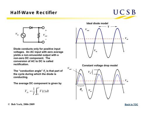
Diode conducts only for positive input<br />
voltages. An AC input with zero average<br />
yields a non-sinusoidal output with a<br />
non-zero DC component. The<br />
conversion of AC to DC is called<br />
rectification.<br />
The “conduction angle” θ c is that part of<br />
the cycle during which the diode is<br />
conducting.<br />
The average DC component is given by<br />
T 1<br />
Vdc V() t dt<br />
T 0<br />
V out<br />
Ideal diode model<br />
T<br />
© Bob York, 2006-2009 Back to TOC<br />
θ c<br />
V out<br />
V in<br />
Constant voltage drop model<br />
vd<br />
V in<br />
V dc<br />
V dc
<strong>Half</strong>-<strong>Wave</strong> <strong>Rectifier</strong><br />
Assume constant voltage drop model<br />
V () t V sint<br />
in m<br />
Vin<br />
() t vdVin vd<br />
Vout () t <br />
0 otherwise<br />
Conduction Angle<br />
t<br />
sin<br />
v <br />
1 d<br />
on <br />
Vm<br />
<br />
t off<br />
sin<br />
v <br />
1 d<br />
<br />
Vm<br />
<br />
1 v d<br />
c ( toff ton) 2sin <br />
Vm 2vd<br />
c <br />
Vm<br />
for vd Vm<br />
Ideal rectifier:<br />
vd<br />
0<br />
c T toff<br />
1 1<br />
Vdc Vout () t dt Vmsintvddt T0Tton V<br />
Vm<br />
0.318V<br />
<br />
V <br />
m <br />
2<br />
vd 1<br />
2<br />
Vm c<br />
v <br />
d <br />
2 Vm<br />
V m vd Vdc 1 2Vm 2<br />
v d 2 <br />
2Vm<br />
<br />
for vdVm Average DC Value<br />
© Bob York, 2006-2009 Back to TOC<br />
V out<br />
θ c<br />
vd<br />
V in<br />
T<br />
dc m<br />
V dc
<strong>Half</strong>-<strong>Wave</strong> <strong>Rectifier</strong><br />
Suppose we reverse the diode: now<br />
only the negative portion of the input<br />
signal passes through<br />
V in<br />
V out<br />
Other than the poarity reversal, all<br />
math on conduction angle and DC<br />
magnitude is identical<br />
Ideal diode model<br />
© Bob York, 2006-2009 Back to TOC<br />
V in<br />
θ c<br />
V out<br />
vd<br />
Constant voltage drop model<br />
V dc<br />
V dc
Peak Detector<br />
V in<br />
V out<br />
© Bob York, 2006-2009 Back to TOC
Peak-Detector with Load<br />
Any load or leakage path will discharge the<br />
capacitor. In this case, the output will<br />
depend on how the RC time constant<br />
compares with the period of the input signal.<br />
Vin C Vout 10 kΩ<br />
The plots at right consider the various<br />
cases for the simple circuit above with<br />
a 1kHz, 5V sinusoidal input<br />
τ = RC<br />
T = 1 mS<br />
For τ «T, circuit acts like an ideal rectifier<br />
For τ »T, circuit acts like an ideal peak detector<br />
C = 10 nF<br />
C = 100 nF<br />
C = 1000 nF<br />
τ = 0.1 T<br />
τ = T<br />
τ = 10 T<br />
© Bob York, 2006-2009 Back to TOC
Peak-Detector as an AM Demodulator<br />
Output of detector<br />
Amplitude-modulated signal<br />
© Bob York, 2006-2009 Back to TOC