This Rigger's Handbook is dedicated to Theodore C - Igor Chudov
This Rigger's Handbook is dedicated to Theodore C - Igor Chudov
This Rigger's Handbook is dedicated to Theodore C - Igor Chudov

You also want an ePaper? Increase the reach of your titles
YUMPU automatically turns print PDFs into web optimized ePapers that Google loves.
General Information<br />
The Rated Load Values for blocks shown in Crosby Group<br />
literature are shown as "Working Loads," "Safe Working<br />
Load" and "Resultant Safe Working Load"; and all these<br />
terms are defined as the maximum amount of <strong>to</strong>tal load that<br />
should be exerted on the block and its fitting, the fitting being<br />
a hook, shackle, eye, loop, etc.<br />
It must be recognized that th<strong>is</strong> <strong>to</strong>tal load value MAY BE<br />
DIFFERENT than the weight being lifted or pulled by a<br />
ho<strong>is</strong>ting or hauling system and, therefore, it <strong>is</strong> necessary <strong>to</strong><br />
determine the <strong>to</strong>tal load being imposed on each block in the<br />
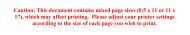
LOADS ON BLOCKS<br />
ANGLE FACTOR ANGLE FACTOR ANGLE FACTOR<br />
0° 2.00 60° 1.73 130° .84<br />
10° 1.99 70° 1.64 135° .76<br />
20° 1.97 80° 1.53 140° .68<br />
30° 1.93 90° 1.41 150° .52<br />
40° 1.87 100° 1.29 160° .35<br />
45° 1.84 110° 1.15 170° .17<br />
50° 1.81 120° 1.00 180° .00<br />
WINCH<br />
LINE<br />
PULL<br />
B<br />
135°<br />
Example: Ho<strong>is</strong>ting system using a traveling block <strong>to</strong> lift a<br />
weight of 1,000 lbs.<br />
The mechanical advantage at the traveling block C <strong>is</strong> 2<br />
because 2 parts of a load line support the 1,000 lbs. weight; so,<br />
the line pull equals the 1,000 lbs. divided by 2 or 500 lbs.<br />
Total load on traveling block shown as C equals 500 lbs. times<br />
angle fac<strong>to</strong>r for 0°.<br />
Total Load on C = 500 x 2.00 = 1,000 lbs.<br />
Total load on stationary block shown as D equals the dead end<br />
load of 500 lbs. plus the line pull of 500 lbs. times the angle<br />
fac<strong>to</strong>r for 40°.<br />
Total Load on E = 500 x .84 = 420 lbs.<br />
Total load on block shown as F equals 500 lbs. times the angle<br />
fac<strong>to</strong>r for 90°.<br />
Total Load on F = 500 x 1.41 = 705 lbs.<br />
50°<br />
A<br />
1000 LBS<br />
HEADQUARTERS: 55 James E. Casey Drive • Buffalo, NY 14206 PHONE: 716.826.2636 FAX: 716.826.4412 www.hanessupply.com<br />
138<br />
system in order <strong>to</strong> properly determine the rated capacity<br />
block <strong>to</strong> be used.<br />
A single sheave block that <strong>is</strong> used <strong>to</strong> change direction of a<br />
load line can be subjected <strong>to</strong> <strong>to</strong>tal loads GREATLY<br />
DIFFERENT than the weight being lifted or pulled. The<br />
amount of <strong>to</strong>tal load changes with the angle between the<br />
incoming and departing lines <strong>to</strong> the block.<br />
The following chart indicates the fac<strong>to</strong>r that <strong>is</strong> multiplied by<br />
the line pull <strong>to</strong> obtain the <strong>to</strong>tal load on the block:<br />
ANGLE<br />
TOTAL LOAD<br />
LINE PULL LINE PULL<br />
Example: A gin pole truck being used <strong>to</strong> lift a weight of<br />
1,000 lbs.<br />
There <strong>is</strong> no mechanical advantage <strong>to</strong> a single part load line<br />
system, so, whinch line pull <strong>is</strong> equal <strong>to</strong> 1,000 lbs. or the<br />
weight being lifted.<br />
Total load on snatch block shown as A equals 1,000 lbs.<br />
times angle fac<strong>to</strong>r for 50°.<br />
Total load on A = 1,000 x 1.81 = 1,1810 lbs.<br />
Total load on <strong>to</strong>ggle block shown as B equals 1,000 lbs.<br />
times angle fac<strong>to</strong>r for 135°.<br />
Total load on B = 1,000 x .76 = 760 lbs.<br />
F<br />
YOUR SLING AND RIGGING SPECIALIST<br />
50°<br />
130°<br />
E<br />
40°<br />
0°<br />
1000 LBS<br />
D<br />
C