Programm Photovoltaik Ausgabe 2009 ... - Bundesamt für Energie BFE
Programm Photovoltaik Ausgabe 2009 ... - Bundesamt für Energie BFE
Programm Photovoltaik Ausgabe 2009 ... - Bundesamt für Energie BFE

Create successful ePaper yourself
Turn your PDF publications into a flip-book with our unique Google optimized e-Paper software.
11/16<br />
Efficiency [%]<br />
FF [%]<br />
9.5<br />
9.0<br />
8.5<br />
8.0<br />
7.5<br />
7.0<br />
6.5<br />
6.0<br />
5.5<br />
5.0<br />
80<br />
75<br />
70<br />
65<br />
60<br />
55<br />
50<br />
Initial<br />
Stable<br />
400 300 nm 200 nm 140 nm<br />
initial<br />
stable<br />
400 nm 300 nm 200 nm 140 nm<br />
30<br />
25<br />
20<br />
15<br />
10<br />
20<br />
18<br />
16<br />
14<br />
12<br />
10<br />
8<br />
6<br />
Degradation [%]<br />
degradation [%]<br />
V oc [mV]<br />
J sc [mA/cm 2 ]<br />
910<br />
900<br />
890<br />
880<br />
870<br />
860<br />
850<br />
840<br />
830<br />
820<br />
810<br />
800<br />
15<br />
14<br />
13<br />
12<br />
11<br />
10<br />
initial<br />
stable<br />
400 nm 300 nm 200 nm 140 nm<br />
400 nm 300 nm 200 nm 140 nm<br />
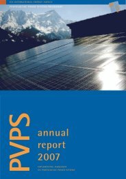
Fig.15: Dependency of a-Si n-i-p solar cell parameters on absorber layer thickness; initial and stable<br />
values are denoted by squares and circles, respectively. Triangles refer to the relative degradation<br />
on the scale to the right. The cells are deposited on glass coated with LP-CVD ZnO.<br />
3.3.3 Micromorph tandem cells with textured intermediate reflector [Sod09]<br />
A particularity of the n-i-p configuration is that the deposition is started with the thick bottom cell.<br />
Fig.14 shows that the collision of growth fronts can result in pinched regions and eventually in the<br />
formation of defective material which is highlighted by the arrow the centre of the film shown in the left<br />
panel. Apart from this observation, the microcrystalline material normally tends to smooth out any existing<br />
structure which poses a challenge to the light trapping strategy for n-i-p tandem cells. For light<br />
trapping in the bottom cell the texture of the back reflector should be relatively large (in the order of 1<br />
to 1.5 µm). As such it will be already too large for light trapping in the amorphous top cell which works<br />
best with structures in the order of 300 nm, and additionally it is smoothened out by the growth of the<br />
bottom cell.<br />
In order to solve this dilemma, an asymmetrical intermediate reflector of LPCVD-ZnO was introduced.<br />
This material is known to develop its own intrinsic surface structure, almost independently of the substrate<br />
it grows on. This configuration allows a separation of the two different light trapping requirements;<br />
the bottom cell is grown on a well adapted substrate for microcrystalline cells like the 2D grating<br />
or a hot silver substrate. Then, the textured ZnO reflector is grown which delivers an ideal texture<br />
for the amorphous top cell which is identical to the case of the cells presented in Fig.15.<br />
Fig.16 shows the EQE and J-V characteristics of a tandem device on glass with initial efficiency of<br />
10.3% and a stabilized efficiency of 10.1%. Because all processes are kept compatible with processing<br />
on plastic substrates, it was also possible to apply the recipes to the flexible plastic substrate with<br />
the 2D grating structure. A corresponding device on plastic is shown in the separate report on the EU-<br />
Project Flexcellence and reaches 9.8% stabilised efficiency, with further space for improvement.<br />
initial<br />
stable<br />
41/290<br />
New processes and device structures for the fabrication of high efficiency thin film silicon photovoltaic modules, C. Ballif, University of Neuchâtel<br />
14<br />
12<br />
10<br />
8<br />
6<br />
4<br />
2<br />
4<br />
2<br />
0<br />
degradation [%]<br />
Degradation [%]