Programm Photovoltaik Ausgabe 2009 ... - Bundesamt für Energie BFE
Programm Photovoltaik Ausgabe 2009 ... - Bundesamt für Energie BFE
Programm Photovoltaik Ausgabe 2009 ... - Bundesamt für Energie BFE

You also want an ePaper? Increase the reach of your titles
YUMPU automatically turns print PDFs into web optimized ePapers that Google loves.
Forschung, April <strong>2009</strong><br />
<strong>Programm</strong> <strong>Photovoltaik</strong> <strong>Ausgabe</strong> <strong>2009</strong><br />
Überblicksbericht, Liste der Projekte<br />
Jahresberichte der Beauftragten 2008<br />
ausgearbeitet durch:<br />
NET Nowak <strong>Energie</strong> & Technologie AG
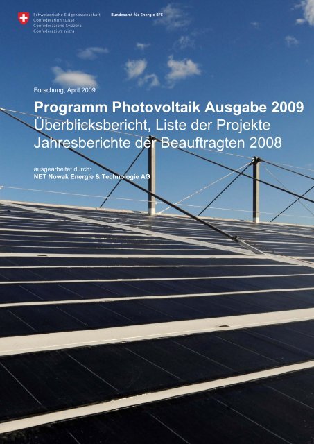
Titelbild:<br />
Das grösste Dachfolien-Solarkraftwerk der Schweiz: Stadion Gründenmoos in St. Gallen<br />
Austragungsort des international bekannten Pferdesportturniers CSIO Schweiz<br />
Fläche: 1200 m 2 ; Bauherrschaft: Sankt Galler Stadtwerke; Baujahr: 2008.<br />
Foto + Projekt: energiebüro® ag / Zürich / Schweiz - <strong>für</strong> Solarkraftwerke<br />
ausgearbeitet durch:<br />
NET Nowak <strong>Energie</strong> & Technologie AG<br />
Waldweg 8, CH - 1717 St. Ursen (Schweiz)<br />
Tel. +41 (0) 26 494 00 30, Fax. +41 (0) 26 494 00 34, info@netenergy.ch<br />
im Auftrag des:<br />
<strong>Bundesamt</strong> <strong>für</strong> <strong>Energie</strong> <strong>BFE</strong><br />
Mühlestrasse 4, CH - 3063 Ittigen Postadresse: CH- 3003 Bern<br />
Tel. +41 (0) 31 322 56 11, Fax. +41 (0) 31 323 25 00 office@bfe.admin.ch www.bfe.admin.ch
<strong>Programm</strong> <strong>Photovoltaik</strong> <strong>Ausgabe</strong> <strong>2009</strong><br />
Forschung<br />
Inhalt<br />
S. Nowak<br />
Überblicksbericht des <strong>Programm</strong>leiters Seite 5<br />
Jahresberichte der Beauftragten Seite<br />
Solarzellen<br />
C. Ballif, A. Feltrin, F. Sculatti-Meillaud, S. Fay, F.J. Haug, V. Terrazzoni-Daudrix,<br />
R. Theron, R. Tscharner<br />
New processes and device structures for the fabrication of high efficiency<br />
thin film silicon photovoltaic modules - 101191 / 153032<br />
F.J. Haug<br />
Flexible photovoltaics: next generation high efficiency and low cost thin film<br />
silicon modules - CTI 8809.2<br />
S. De Wolf, S. Olibet, J. Damon-Lacoste, L. Fesquet, C. Ballif<br />
High efficiency thin-film passivated silicon solar cells and modules -<br />
THIFIC: Thin film on crystalline Si - Axpo Naturstrom Fonds 0703<br />
S. De Wolf, J. Damon-Lacoste, L. Fesquet, S. Olibet C. Ballif<br />
HETSI: Heterojunction Solar Cells based on a-Si / c-Si - HETSI no.: 211821 55<br />
V. Terrazzoni, F-J. Haug, C. Ballif<br />
FLEXCELLENCE: Roll-to-roll technology for the production of high efficiency<br />
low cost thin film silicon photovoltaic modules - SES-CT-019948<br />
1/290<br />
31<br />
47<br />
51<br />
59
N. Wyrsch, C. Ballif<br />
ATHLET: Advanced Thin Film Technologies for Cost Effective Photovoltaics -<br />
IP 019670<br />
D. Gablinger, R. Morf<br />
Zweidimensionale Nanostrukturen <strong>für</strong> Silizium-Solarzellen - 102807 / 153611 69<br />
X. Maeder, J. Michler<br />
HIGH-EF - Large grained, low stress multi-crystalline silicon thin film<br />
solar cells on glass by a novel combined diode laser and solid phase<br />
crystallization process - EU FP7 213303<br />
D. Brémaud, P. Blösch, D. Güttler, A.N. Tiwari<br />
Large Area flexible CIGS: Flexible CIGS solar cells on large area polymer foils<br />
with in-line deposition methods and application of alternative back contacts -<br />
100964 / 152404<br />
A. N. Tiwari, C. Hibberd, Y.E. Romanyuk<br />
Thin Film CIGS Solar Cells with a Novel Low Cost Process – 100964 / 152223 87<br />
D. Güttler, A. Chirila, Dr. A. N. Tiwari<br />
LARCIS: Large-Area CIS Based Solar Modules for Highly Productive<br />
Manufacturing - SES66-CT-2005-019757 / FP6-019757<br />
D. Güttler, S. Bücheler, S. Seyrling, R. Verma, A. N. Tiwari<br />
ATHLET: Advanced Thin-Film Technologies for Cost Effective Photovoltaics -<br />
ATHLET CIS / FP-2204-Energy-3<br />
A. N. Tiwari<br />
Laser patterning of Cu(In,Ga)Se2 solar cells on flexible foils for monolithic<br />
integration - KTI 8697.2<br />
R. Kern, M. Kaelin<br />
Development of flexible CIGS Solar Modules with metal Grids -<br />
Axpo Naturstrom Fonds<br />
M. Graetzel, F. Sauvage, S. M. Zakeeruddin<br />
Efficient and Robust Dye Sensitzed Solar Cells and Modules - FP7-212792 /<br />
ROBUST DSC<br />
J.O. Schumacher, M. Schmid, G. Rothenberger, S. Wenger<br />
ModSol: Modeling, simulation and loss analysis of dye-sensitized solar cells -<br />
GRS-064/07<br />
R. Hany, F.A. Castro, F. Nüesch, J. Heier<br />
Organic photovoltaic devices - EMPA Projekt 131<br />
2/290<br />
63<br />
73<br />
79<br />
95<br />
105<br />
115<br />
119<br />
121<br />
127
B. Ruhstaller, R. Häusermann, N. A. Reinke, C. Winnewisser,<br />
T. Offermans, M. Turbiez, M. Düggeli, R. Janssen, J. Bisquert<br />
Apollo: Efficient areal organic solar cells via printing -102738 / 153575<br />
T. Meyer<br />
OrgaPvNet: Coordination action towards stable and low-cost organic<br />
solar cell technologies and their application - SES6-038889<br />
T. Meyer, A. Meyer<br />
NAPOLYDE: Nano structured polymer deposition processes for mass production<br />
of innovative systems for energy production & control and for smart devices -<br />
NMP2-CT-2005-515846 / SER N° 03.0111-2<br />
T. Meyer, A. Meyer<br />
FULLSPECTRUM: A new PV wave making more efficient use of the solar<br />
spectrum - SES6-CT-2003-502620 / SER N° 03.0111-2<br />
D. Brühwiler<br />
Development of efficient luminescent concentrators based on inorganic/organic<br />
nanomaterials for applications in solar energy conversion - KTI 9231.2<br />
F. Nüesch, A. Feltrin, G. Bugnon, F. Meillaud, J. Bailat, C. Ballif, B. Legradic,<br />
C. Hollenstein, R. Häusermann, B. Ruhstaller, S. Wenger, P. Liska, M. Grätzel,<br />
S. Seyrling , D. Brémaud, A. Tiwari, B. Fan, J.-E. Moser<br />
ThinPV - Cost efficient thin film photovoltaics for future electricity generation 169<br />
A. Luzzi, M. Spirig<br />
PECNet: Aufbau eines Schweizer Kompetenznetzwerks <strong>für</strong> die Solare<br />
Wasserspaltung mittels hybrider PV-PEC Zellen -101883 / 152316<br />
Module und Gebäudeintegration<br />
T. Szacsvay<br />
Smarttile: Innovative <strong>Photovoltaik</strong>-Indachlösung – 102682 / 153473 187<br />
Y. Leterrier, J. Rion, L. Lalande, P. Liska, A. Vasilopoulos<br />
Ultralight Photovoltaic Structures – CTI 8002.1 DCS-NM 191<br />
3/290<br />
135<br />
141<br />
145<br />
153<br />
163<br />
175
Systemtechnik<br />
D. Chianese, N. Cereghetti, A. Realini, G. Friesen, E. Burà, I. Pola,<br />
T. Friesen, R. Rudel<br />
Centrale di test ISAAC-TISO: Qualità e resa energetica di moduli fotovoltaici -<br />
36508 / 153027<br />
G. Friesen, I. Pola, T. Friesen, K. Nagel, F. Morini, A. Jimenez<br />
PERFORMANCE - ISAAC Activities - n° 019718 EU: (SES6) – Integrated project 209<br />
H. Häberlin, L. Borgna, D. Gfeller, M. Kämpfer, M. Münger, Ph. Schärf, U. Zwahlen<br />
<strong>Photovoltaik</strong> Systemtechnik 2007-2010 / PVSYSTE 07-10 - 102234 / 152840 217<br />
P. Gaillard<br />
SoS-PVi: Security of Supply Photovoltaic Inverter - 019883 (SeS6) 225<br />
Internationale Koordination<br />
P. Hüsser<br />
Schweizer Beitrag zum IEA PVPS <strong>Programm</strong> - Task 1 - 11427 / 153243 235<br />
Th. Nordmann, L. Clavadetscher<br />
Schweizer Beitrag zum IEA PVPS <strong>Programm</strong> - Task 2 2008 - 14805 / 153587 241<br />
S. Nowak, M. Ndoh Rossier, C. Spörndli<br />
REPIC: Swiss Interdepartmental Platform for Renewable Energy and Energy<br />
Efficiency Promotion in International Cooperation - SECO UR-00123.01.01<br />
P. Renaud, L. Perret<br />
IEA PVPS Task 10 – Swiss contribution - 101562 / 151862 259<br />
R. Frischknecht, M. Stucki<br />
IEA-PVPS Task 12: Swiss activities in 2008 - Aktualisierung der Ökobilanz<br />
von CdTe - PV - 11427 / 153382<br />
J. Remund<br />
IEA SHC Task 36: Solar resource knowledge management - 101498 / 151784 271<br />
P. Toggweiler, T. Hostettler<br />
Normierung <strong>für</strong> PV-Systeme - Swissolar 277<br />
S. Nowak, M. Gutschner, S. Gnos, S. Oberholzer<br />
PV-ERA-NET: Networking and Integration of National and Regional <strong>Programm</strong>es in<br />
the Field of Photovoltaic (PV) Solar Energy Research and Technological<br />
Development (RTD) in the European Research Area (ERA) - CA-011814-PV ERA NET<br />
4/290<br />
201<br />
247<br />
265<br />
283
PROGRAMM PHOTOVOLTAIK<br />
Eidgenössisches Departement <strong>für</strong><br />
Umwelt, Verkehr, <strong>Energie</strong> und Kommunikation UVEK<br />
<strong>Bundesamt</strong> <strong>für</strong> <strong>Energie</strong> <strong>BFE</strong><br />
Überblicksbericht zum Forschungsprogramm 2008<br />
Stefan Nowak<br />
stefan.nowak@netenergy.ch<br />
Power P [kW]<br />
I-V- and P-V-Diagram of BFH-TI's PV Array Simulator (FF 80%)<br />
100<br />
75<br />
50<br />
25<br />
P = f(V)<br />
Pmpp<br />
I = f(V)<br />
PMPP = 100.57 kW<br />
0<br />
0 100 200 300 400 500 600 700 800<br />
Voltage [V]<br />
160<br />
120<br />
80<br />
40<br />
PV laboratory of BFH-TI, Burgdorf<br />
100 kW Solargenerator Simulator<br />
Am <strong>Photovoltaik</strong>labor der BFH-TI in Burgdorf wurde ein 100 kW Solargenerator Simulator aufgebaut,<br />
welcher weltweit der grösste seiner Art ist. Mit diesem Gerät können Wirkungsgradkennlinien und<br />
Maximum Power Point Tracking (MPPT) von Wechselrichtern bis zu 100 kW Leistung gemessen werden.<br />
(Bildquelle: BFH-TI)<br />
5/290<br />
0<br />
Current I [A]
Inhaltsverzeichnis<br />
1. <strong>Programm</strong>schwerpunkte und anvisierte Ziele ........................................................................ 7<br />
2. Durchgeführte Arbeiten und erreichte Ergebnisse 2008........................................................ 9<br />
Zell-Technologie ........................................................................................................................... 9<br />
Solarmodule und Gebäudeintegration........................................................................................ 15<br />
Elektrische Systemtechnik.......................................................................................................... 15<br />
Begleitende Themen .................................................................................................................. 17<br />
Internationale Zusammenarbeit IEA, IEC, EU............................................................................ 17<br />
3. Nationale Zusammenarbeit...................................................................................................... 19<br />
4. Internationale Zusammenarbeit .............................................................................................. 19<br />
5. Pilot- und Demonstrationsprojekte (P+D).............................................................................. 20<br />
Neue P+D Projekte..................................................................................................................... 20<br />
Laufende P+D Projekte .............................................................................................................. 20<br />
Im Jahr 2008 abgeschlossene P+D Projekte ............................................................................. 21<br />
6. Bewertung 2008 und Ausblick <strong>2009</strong> ....................................................................................... 22<br />
7. Liste der F+E-Projekte ............................................................................................................. 23<br />
8. Liste der P+D-Projekte ............................................................................................................. 25<br />
9. Referenzen ................................................................................................................................ 25<br />
10. Für weitere Informationen ....................................................................................................... 26<br />
11. Verwendete Abkürzungen (inkl. Internetlinks) ...................................................................... 27<br />
12. Weiterführende Internetlinks................................................................................................... 27<br />
6/290
1. <strong>Programm</strong>schwerpunkte und anvisierte Ziele<br />
Die <strong>Photovoltaik</strong> erfuhr im Jahr 2008 weltweit wie auch in der Schweiz einen weiteren Aufschwung,<br />
wobei sich im letzten Quartal erwartungsgemäss auch Auswirkungen der globalen Wirtschaftskrise auf<br />
die <strong>Photovoltaik</strong> und eine Verlangsamung der Entwicklung abzeichneten. Vom allgemeinen Aufschwung<br />
war auch das <strong>Programm</strong> <strong>Photovoltaik</strong> massgeblich betroffen, indem das Interesse von Forschung<br />
und Industrie am Thema weiter gross ist und sich die Schweizer Industrie Aktivitäten weiter<br />
verstärkten. Durch die im Verlauf von 2008 eingeführte kostendeckende Vergütung <strong>für</strong> Strom aus<br />
erneuerbaren <strong>Energie</strong>n gewannen anwendungsorientierte Fragestellungen an zusätzlicher Bedeutung.<br />
Durch die breite <strong>Programm</strong>abstützung im Bereich der Forschung konnte der bisherige Umfang<br />
des <strong>Programm</strong>s im Jahr 2008 übertroffen werden. Das anhaltende Wachstum des internationalen<br />
<strong>Photovoltaik</strong> Marktes bildet eine wichtige Grundlage <strong>für</strong> den weiterhin erfolgenden, deutlichen Ausbau<br />
der <strong>Photovoltaik</strong> Industriebasis in der Schweiz. Die Kompetenz der Schweizer <strong>Photovoltaik</strong> Forschung<br />
ist mehr denn je gefragt und führt immer häufiger zu industrieorientierten Projekten.<br />
Das <strong>Programm</strong> <strong>Photovoltaik</strong> verfolgt eine ausgeprägte Ausrichtung auf die industrielle Umsetzung und<br />
die internationale Wettbewerbsfähigkeit, sowohl <strong>für</strong> Produkte wie auch <strong>für</strong> die vorgelagerte Forschung.<br />
Laufende Aktivitäten in Forschung und Entwicklung sowie noch bestehende Projekte im Bereich von<br />
Pilot- und Demonstrationsanlagen umfassen im Berichtsjahr 2008 ca. 50 Projekte, wobei alle bekannten<br />
Projekte mit einer Förderung der öffentlichen Hand berücksichtigt sind.<br />
Gestützt auf das <strong>Energie</strong>forschungskonzept der Eidgenössischen <strong>Energie</strong>forschungskommission<br />
CORE [59] verfolgt das Schweizer <strong>Photovoltaik</strong> <strong>Programm</strong> in der Periode 2008 – 2011 die folgenden<br />
wesentlichen Ziele [60]:<br />
- Senkung der Kosten der Solarzellen und -module<br />
- Kostenziel 2011 Modul 3 Fr./W, System 5 Fr./W<br />
- Steigerung des Wirkungsgrades (Solarzellen)<br />
- Senkung des Material- und <strong>Energie</strong>einsatzes<br />
- Vereinfachung und Standardisierung der elektrischen Systemtechnik, Steigerung der Lebensdauer<br />
und Zuverlässigkeit von Wechselrichtern<br />
- Erhöhung der Verfügbarkeit und der Vielfalt industrieller Produkte<br />
Dazu ist das <strong>Programm</strong> <strong>Photovoltaik</strong> in folgende Bereiche aufgeteilt:<br />
SOLARZELLEN DER ZUKUNFT<br />
Die Arbeiten zu Dünnschichtsolarzellen waren im Berichtsjahr wie bisher fokussiert auf die Schwerpunkte<br />
Silizium (amorph, mikrokristallin), Zellen auf der Basis von Verbindungshalbleitern (CIGS)<br />
sowie Farbstoffzellen. Die Grundlagen <strong>für</strong> organische und Polymersolarzellen als mögliche langfristige<br />
Technologieoptionen gewinnen gesamthaft an Bedeutung und bewegen sich gleichzeitig vom<br />
Konzept zur Solarzelle. Die mit Nachdruck verfolgte Industrialisierung von Produktionsprozessen steht<br />
bei den Silizium Dünnschichtsolarzellen in einem fortgeschrittenen Stadium, bei den Verbindungshalbleitern<br />
ist ein industrielles Projekt im Aufbau. Im Jahr 2008 wurden die Industrieprojekte <strong>für</strong> grössere<br />
Fertigungsanlagen mit Dünnschichtsolarzellen vorangetrieben. Solarzellen auf flexiblen Substraten<br />
gewinnen zudem weiterhin an Bedeutung.<br />
Gemäss <strong>Energie</strong>forschungskonzept der CORE 2008 – 2011 [59] lauten die Ziele <strong>für</strong> den Bereich Solarzellen:<br />
- Industrielle Fertigung von Solarzellen und –modulen auf Basis von Dünnschichttechnologien mit<br />
dem Ziel von wettbewerbsfähigen Herstellungsprozessen und Produkten (Zellen, Module)<br />
- Mittel- und Langfristige Materialoptionen <strong>für</strong> Solarzellen der Zukunft (z.B. organische und polymere<br />
Solarzellen) mit dem Ziel, dazu die internationale Zusammenarbeit in Europa auszubauen<br />
- Fertigungsprozesse <strong>für</strong> dünnere Wafer mit dem Ziel einer Waferdicke von 150 µm<br />
Die Ziele <strong>für</strong> den Bereich der Solarzellen werden im Detailkonzept <strong>Photovoltaik</strong> [60] weiter präzisiert.<br />
Die Forschungsarbeiten an Solarzellen stellen bezüglich Mitteleinsatz den wichtigsten Bereich des<br />
Schweizer <strong>Photovoltaik</strong>-<strong>Programm</strong>s dar. Entsprechend kommen auch diverse Förderinstrumente zum<br />
Einsatz.<br />
7/290
MODULE UND GEBÄUDEINTEGRATION<br />
Das Gebiet der Solarmodule ist im <strong>Programm</strong> <strong>Photovoltaik</strong> eng mit der Anwendung der Gebäudeintegration<br />
verbunden. Im Vordergrund stehen Modultechnologien, welche mit den in der Schweiz entwickelten<br />
Solarzellen einhergehen. Forschungsthemen in diesem Bereich können neue bzw. verbesserte<br />
Verfahren zur Herstellung von Solarmodulen (z.B. Verpackung, Verschaltung, neue Materialien)<br />
sowie deren Eigenschaften (z.B. Langzeitstabilität, mechanische, optische und thermische Eigenschaften)<br />
sein.<br />
Gemäss <strong>Energie</strong>forschungskonzept der CORE 2008 – 2011 [59] lauten die Ziele <strong>für</strong> den Bereich Solarmodule<br />
und Gebäudeintegration:<br />
- Echte Integration von Dünnschichtsolarzellen in neue Produkte <strong>für</strong> die Gebäudeintegration mit<br />
dem Ziel, neue <strong>Photovoltaik</strong>-Gebäude-Komponenten, insbesondere mit Dünnschichttechnologie,<br />
industriell zu fertigen<br />
- Produktsynergien der <strong>Photovoltaik</strong> mit der Gebäudetechnik, in der Gebäudehülle ebenso wie mit<br />
der Haustechnik (z.B. Brennstoffzellen), mit dem Ziel, neue Lösungsansätze <strong>für</strong> die Optimierung<br />
der <strong>Energie</strong>produktion und der <strong>Energie</strong>nutzung im Gebäude zu erarbeiten<br />
ELEKTRISCHE SYSTEMTECHNIK<br />
Die elektrische Systemtechnik, insbesondere <strong>für</strong> Wechselrichter, ist weit fortgeschritten und entsprechend<br />
besteht ein breites Angebot am Markt, inklusive diversen erfolgreichen Schweizer Produkten.<br />
Die notwendige Weiterentwicklung der Wechselrichter erfolgt zumeist durch die Industrie. Dagegen ist<br />
die Qualitätssicherung in diesem Schwerpunkt sicherzustellen ebenso wie dazu erforderlichen Prozeduren<br />
(z.B. Zertifizierung von Produkten). Punktueller Bedarf entsteht durch allgemeine Fortschritte<br />
in der elektrischen Systemtechnik und neue Anwendungen.<br />
Neue Optionen in der elektrischen Systemtechnik werden durch die fortschreitende elektrische Haustechnik<br />
ermöglicht. In Zukunft werden Informationen über den Betriebszustand diverser haustechnischer<br />
Anlagen in verstärktem Ausmass ausgetauscht werden.<br />
Die elektrischen Systemkomponenten sind in einer <strong>Photovoltaik</strong> Anlage diejenigen Komponenten,<br />
welche in der Vergangenheit zu den schwächsten Gliedern gehörten und <strong>für</strong> zahlreiche Ausfälle verantwortlich<br />
waren. Obwohl sich diese Situation in den letzten Jahren verbessert hat, bleibt das Langzeitverhalten<br />
von <strong>Photovoltaik</strong> Komponenten und Anlagen ein wichtiges Anliegen, welches durch einige,<br />
jedoch begrenzte Analysen vertieft werden soll. Die Zuverlässigkeit und Sicherheit von <strong>Photovoltaik</strong>-Komponenten<br />
und Anlagen sind Gebiete, die in letzter Zeit vermehrt Beachtung gefunden haben<br />
(z.B. Lichtbogen).<br />
Ein in Zukunft wichtiger werdendes Thema ist die Integration der <strong>Photovoltaik</strong> im elektrischen Netz.<br />
Dies betrifft weniger die Fragen in Bezug auf eine einzelne Anlage als vielmehr die Wechselwirkung<br />
einer grösseren Zahl von <strong>Photovoltaik</strong>-Anlagen mit dem elektrischen Netz. Im Zusammenhang mit der<br />
erwarteten Entwicklung von Smart-Grids können sich neue Anforderungen und Chancen <strong>für</strong> die <strong>Photovoltaik</strong><br />
ergeben. Es interessieren hier in erster Linie <strong>Photovoltaik</strong> spezifische Fragestellungen.<br />
Gemäss <strong>Energie</strong>forschungskonzept der CORE 2008 – 2011 [59] lauten die Ziele <strong>für</strong> den Bereich<br />
Elektrische Systemtechnik:<br />
- Neue Systemkomponenten <strong>für</strong> netzgekoppelte Anlagen, Insel- und Hybridsysteme mit dem Ziel<br />
von integrierten Produktlösungen <strong>für</strong> den kombinierten Netz-, Insel und Hybridbetrieb<br />
- Dezentrale <strong>Energie</strong>erzeugungssysteme, <strong>Energie</strong>speicherung und <strong>Energie</strong>nutzung mit dem Ziel<br />
einer aktiven Verbrauchssteuerung<br />
BEGLEITENDE THEMEN<br />
In diesem die Technik zum Teil ergänzenden Bereich werden einerseits allgemeine, <strong>für</strong> die weitere<br />
Marktentwicklung der <strong>Photovoltaik</strong> notwendige Voraussetzungen sichergestellt, z.B. in Bezug auf fortgeschrittene<br />
Hilfsinstrumente <strong>für</strong> die Planung und das Monitoring von <strong>Photovoltaik</strong>-Anlagen, die Quantifizierung<br />
von Umweltaspekten, usw.. Um die Marktrelevanz sicherzustellen, sind solche Projekte in<br />
enger Zusammenarbeit mit den entsprechenden Stellen auszuführen.<br />
8/290
Eine zweite Kategorie von Projekten in diesem Schwerpunkt bilden neue, in Kombination mit anderen<br />
<strong>Energie</strong>formen mögliche Anwendungen der <strong>Photovoltaik</strong>, sei es mit anderen Formen der Sonnenenergie<br />
(Solararchitektur und thermische Solarenergie), in Konzepten der nachhaltigen Mobilität (Elektromobile,<br />
Solarboote, usw.) oder in Kombination mit anderen <strong>Energie</strong>trägern (z.B. Wasserstoff,<br />
Thermophotovoltaik). Auch hier ist eine gute Koordination mit entsprechenden Förderstellen sicherzustellen<br />
und die eigentliche Entwicklung fachbezogen einzugrenzen. Dies bedeutet, dass sowohl die<br />
primäre energetische Nutzung wie der spezifische Entwicklungsbedarf identifiziert werden müssen.<br />
INSTITUTIONELLE INTERNATIONALE ZUSAMMENARBEIT<br />
Die internationale Zusammenarbeit wird grundsätzlich in allen bisher besprochenen Bereichen angestrebt<br />
und ist auch dementsprechend etabliert. Nebst dieser projektbezogenen internationalen Zusammenarbeit<br />
ist diese aber auch auf der Ebene der Institutionen anhaltend zu gewährleisten. Die<br />
bisherigen Erfahrungen und der Nutzen dieser Zusammenarbeit <strong>für</strong> die Schweiz können allgemein als<br />
sehr gut eingestuft werden. Demnach bildet die Kontinuität dieser internationalen Zusammenarbeit ein<br />
strategisches Element des <strong>Programm</strong>s <strong>Photovoltaik</strong>. Angesichts der raschen internationalen Entwicklung<br />
der <strong>Photovoltaik</strong> ist diese Zusammenarbeit in Zukunft in allen Bereichen fortzuführen.<br />
Im Vordergrund stehen folgende internationale Institutionen:<br />
- Europäische Kommission (EC) – Rahmenforschungsprogramme, SET-Plan;<br />
- EU PV Technology Platform (PV TP) – Strategic Research Agenda, SET Plan;<br />
- PV-ERA-NET – Kooperation zwischen europäischen Forschungsprogrammen;<br />
- IEA PVPS – Forschungskooperation im Rahmen der IEA;<br />
- IEC – Normentätigkeit;<br />
- Organisationen zur Entwicklungszusammenarbeit: internationale Organisationen, z.B. gtz, GEF,<br />
IFC, WB.<br />
2. Durchgeführte Arbeiten und erreichte Ergebnisse 2008<br />
ZELL-TECHNOLOGIE<br />
Die grosse Bandbreite der Schweizer Solarzellenforschung konnte im Berichtsjahr 2008 dank der<br />
breiten Abstützung dieser Forschung mit Erfolg fortgesetzt werden. Die Beteiligung an EU-Projekten<br />
des 6. und 7. Rahmenforschungsprogramms sowie KTI-Projekte bildeten hier gewichtige Elemente.<br />
a) Dünnschichtsilizium<br />
Die wesentlichen Entwicklungen im Bereich des Dünnschichtsiliziums finden an der Universität Neuchâtel<br />
(IMT), an der EPFL (CRPP) sowie bei den Unternehmen oerlikon solar (Trübbach und Neuchâtel)<br />
und VHF-Technologies (Yverdon) statt und stellen den wichtigsten Schwerpunkt des <strong>Photovoltaik</strong><br />
<strong>Programm</strong>s dar. Das PSI und die EMPA Thun ergänzen diesen Schwerpunkt mit neuen Ansätzen.<br />
Das IMT an der Universität Neuchâtel begann im Berichtsjahr eine neue Phase des Projektes zu Silizium<br />
Dünnschicht Solarzellen und -modulen [1]. Die Ziele dieses 4-jährigen <strong>BFE</strong>-Projektes bestehen<br />
darin, die Kosten von Silizium Dünnschichtsolarzellen weiter zu senken, wobei amorphes Silizium,<br />
SiGe-Verbindungen und mikrokristallines Silizium Gegenstand der Forschung sind. Es sollen diejenigen<br />
Fortschritte erzielt werden, welche Herstellungskosten < 1 €/Wp bei einem Wirkungsgrad von<br />
> 10% erlauben. Das Projekt befasst sich mit den vier Ebenen Materialien, Prozesse, Komponenten<br />
(Devices) und Zuverlässigkeit und umfasst entsprechende Depositionssysteme (Fig. 1) sowie umfangreiche<br />
analytische Methoden. Die Zusammenarbeit mit der Industrie erfolgte primär mit den Unternehmen<br />
oerlikon solar und VHF-Technologies, welche die am IMT entwickelten Prozesse in ihre Produkte<br />
implementieren. Neu hinzugekommen ist seitens der Industriepartner die Firma Roth&Rau, welche<br />
mit dem IMT eine umfangreiche Forschungspartnerschaft eingegangen ist. Folgende Resultate<br />
aus dem Berichtsjahr seien hier erwähnt:<br />
9/290
Materialien: Aufbauend auf den Resultaten der Vorjahre <strong>für</strong> amorphe und mikrokristalline Einfach-<br />
Solarzellen (single junction) auf Glassubstraten und der Entwicklung von Zwischenreflektor Schichten<br />
auf der Basis von ZnO bzw. SiOx, wurde eine weitere Erhöhung des Wirkungsgrads der mikromorphen<br />
Solarzelle angestrebt. Mit einer Zwischenreflektor-Schicht aus SiOx wurde im Berichtsjahr der<br />
Wirkungsgrad von mikromorphen Solarzellen auf 1 cm 2 Fläche auf 13.1% erhöht. Für transparente<br />
leitende Oxydschichten (TCO) aus ZnO konnte im Feuchte-Wärme-Test (85ºC, 85% relative Feuchtigkeit)<br />
eine gute Stabilität erzielt werden.<br />
Prozesse: Ein Schwerpunkt war im Berichtsjahr die Herstellung von mikrokristallinem Silizium bei<br />
hohen Abscheideraten. Als Resultat konnte bei einer gegenüber früher deutlich höheren Abscheiderate<br />
von 1 nm/s eine mikrokristalline Einfach-Solarzelle mit einem Wirkungsgrad von 7,1 % hergestellt<br />
werden. Weitere Aktivitäten befassten sich mit der Herstellung von nanotexturierten Substraten sowie<br />
Laser Strukturierung (laser scribing) der Solarzellen zur monolithischen Verschaltung.<br />
Komponenten: Nebst der bereits erwähnten mikromorphen Solarzelle von 13.1% Wirkungsgrad wurden<br />
amorphe (p-i-n) Tandem Solarzellen auf Glas mit einem Anfangswirkungsgrad von 9.8% bzw.<br />
einem stabilisierten Wirkungsgrad von 8.3% erreicht. Für die Anwendung auf Plastiksubstraten wurden<br />
mit einer ZnO Zwischenreflektor Schicht mikromorphe (n-i-p) Solarzellen mit einem stabilisierten<br />
Wirkungsgrad von 10.1% erzielt.<br />
Zuverlässigkeit: Bei dieser am IMT neu aufgebauten Tätigkeit geht es um die zuverlässige Verpackung<br />
der verschiedenen Solarzellen. Die dazugehörigen Arbeiten umfassen die Adhäsion von Polymeren<br />
auf Glas, die Wasserdiffusion in Verpackungsschichten <strong>für</strong> Solarzellen, den Wassergehalt von<br />
Polymeren sowie die Kompatibilität mit der elektrischen Kontaktierung und mit Rückreflektorschichten.<br />
Das KTI-Projekt Flexible Photovoltaics – next generation high efficiency and low cost thin film silicon<br />
modules [2] wurde im Berichtsjahr zwischen dem IMT der Universität Neuchâtel und VHF-<br />
Technologies fortgesetzt. In diesem Vorhaben wird angestrebt, die bisher bei VHF-Technologies in<br />
ihrer ersten Produktgeneration bei flexiblen Solarzellen realisierten Wirkungsgrade von ca. 4.5% signifikant<br />
zu erhöhen. Durch die Verwendung eines rückseitigen, diffus streuenden dielektrischen Reflektors,<br />
einer Substratstrukturierung und einer amorphen Zellenstruktur in Tandemkonfiguration soll der<br />
Wirkungsgrad der industriellen Produkte auf 6% erhöht werden. Auf kleiner Fläche wurden auf Einfachzellen<br />
bzw. Tandemzellen mit einem stabilisierten Wirkungsgrad von 7.3% bzw. 8.0% gute Fortschritte<br />
erzielt. Ein weiteres KTI-Projekt des IMT befasst sich mit transparenten leitenden Oxyden auf<br />
der Grundlage von ZnO [3].<br />
Das durch den Axpo Naturstrom Fonds unterstützte Projekt THIFIC – Thin film on crystalline silicon [4]<br />
wurde am IMT fortgesetzt. In diesem Vorhaben werden extrem effiziente Solarzellen mit 20–22 %<br />
Wirkungsgrad angestrebt. Dabei kommt das bekannte Konzept einer Heteroverbindung (hetero junction)<br />
zwischen kristallinen Silizium-Solarzellen und amorphen bzw. mikrokristallinen Solarzellen zur<br />
Anwendung (HIT-Zelle). Der Fortschritt im Vergleich zu andern HIT-Zellen liegt in der Verwendung von<br />
Siliziumwafern deutlich geringerer Dicke bis gegen 100 µm und der damit verbundenen Material- bzw.<br />
<strong>Energie</strong>einsparung. In Vorarbeiten zu diesem Vorhaben wurde bereits ein Wirkungsgrad von 19%<br />
erreicht. Eine wesentliche Rolle <strong>für</strong> diese Solarzelle kommt der Grenzfläche zwischen dem kristallinen<br />
Siliziumwafer und der amorphen Dünnschichtsolarzelle zu; diese Grenzfläche sollte in Hinsicht auf<br />
den weiteren Schichtaufbau atomar scharf sein. Das bessere Verständnis dieser Grenzfläche führte<br />
im Berichtsjahr zu Solarzellen mit einer Klemmenspannung von 700 mV.<br />
Im neuen EU-Projekt HETSI: Heterojunction solar cells based on a-Si / c-Si [5] arbeitet das IMT auch<br />
international auf dem Thema der Heteroverbindungssolarzelle. Dieses Projekt verbindet zum ersten<br />
Mal zwölf europäische Unternehmen und Forschungsinstitute aus den Gebieten des kristallinen Siliziums<br />
und der Silizium Dünnschichtsolarzellen in einem solchen Projekt. Das Projekt ergänzt die Untersuchungen<br />
zur oben erwähnten Grenzfläche und dem darauf erfolgenden Schichtaufbau der amorphen<br />
Solarzelle. In Hinsicht auf die industrielle Nutzung der Projektergebnisse wurde am IMT ein neues<br />
automatisiertes grossflächiges Depositionssystem (410 x 520 mm 2 ) aufgebaut.<br />
Das EU-Projekt FLEXCELLENCE [6] unter Schweizer Koordination des IMT und Beteiligung von VHF-<br />
Technologies wurde im Berichtsjahr erfolgreich abgeschlossen. In diesem Projekt ging es um flexible<br />
Solarzellen auf Kunststoff- und Metallsubstraten und die da<strong>für</strong> notwendigen Produktionstechnologien.<br />
Im Vorhaben wurden drei unterschiedliche Ansätze zur roll-to-roll Beschichtung untersucht, namentlich<br />
Mikrowellen PECVD (Plasma Enhanced Chemical Vapor Deposition), Hot Wire CVD (Chemical<br />
Vapor Deposition) und VHF PECVD. Das IMT bzw. VHF-Technologies befassen sich mit dem letzten<br />
der drei genannten Verfahren. Am IMT wurde im Berichtsjahr mittels PECVD eine mikromorphe Tandemzelle<br />
auf Kunststoff (PEN) mit einem stabilisierten Wirkungsgrad von 9.8% realisiert (Fig. 2).<br />
10/290
Im Integrierten EU-Projekt ATHLET [7] befassen sich das IMT und oerlikon solar mit der Weiterentwicklung<br />
der Silizium-Dünnschichtsolarzellen. Für mikromorphe Tandemzellen lautet das Ziel 10%<br />
stabiler Wirkungsgrad bei einer Fläche von 1 m 2 und 10 Å/s Depositionsrate bzw. Modulproduktionskosten<br />
von < 0.5 €/Wp. Dieses Projekt ergänzt das eingangs aufgeführte <strong>BFE</strong> Projekt am IMT. Im<br />
Berichtsjahr konnte unter Einsatz der oben erwähnten SiOx-Zwischenreflektorschicht ein Anfangswirkungsgrad<br />
von mikromorphen Solarzellen von 13.3% erreicht werden. Mit einem am IMT neu aufgebauten<br />
industriellen Depositionssystem konnten mikromorphe Solarzellen mit 11 % Wirkungsgrad und<br />
9,4 % stabilisiertem Wirkungsgrad hergestellt werden.<br />
Das IMT wechselte auf Ende 2008 seine institutionelle Anbindung von der Universität Neuchâtel zur<br />
EPFL, wobei der Standort Neuchâtel beibehalten wird.<br />
Figur 1: Automatisiertes Dünnschichtsilizium- Figur 2: Mehrfach Prozesskammer bei<br />
Doppelkammer-Depositionssystem auf der VHF-Technologies<br />
Grundlage der KAI-M plasma box von oerlikon (Bildquelle: IMT)<br />
(Bildquelle: IMT)<br />
Ein neues KTI-Projekt am CRPP der EPFL befasst sich mit der Entwicklung eines neuen PECVD Reaktors<br />
<strong>für</strong> die Deposition von Dünnschicht Solarzellen [8].<br />
Das neue <strong>BFE</strong>-Projekt am PSI Zweidimensionale Nanostrukturen <strong>für</strong> Siliziumsolarzellen [9] geht der<br />
Frage nach optimalen Ansätzen <strong>für</strong> zweidimensionale optische Beugungsstrukturen auf Silizium-<br />
Dünnschichtsolarzellen nach. In einer ersten Phase werden diese numerisch modelliert. Später sollen<br />
solche Strukturen experimentell realisiert und ausgemessen werden. Im Berichtsjahr wurden verschiedene<br />
Algorithmen und deren Konvergenzverhalten untersucht.<br />
Im neuen EU-Projekt High-Ef – Large grained, low stress multi-crystalline silicon thin film solar cells on<br />
glass by a novel combined diode laser and solid phase crystallization process [10] arbeitet die EMPA<br />
Thun an einem neuen Prozess zur Herstellung hocheffizienter Silizium-Dünnschichtsolarzellen. Der<br />
Prozess verbindet eine durch Laserschmelzen verursachte Kristallisation einer amorphen Siliziumschicht<br />
mit der Festphasenepitaxie. Daraus soll ein wettbewerbsfähiger Prozess <strong>für</strong> Dünnschichtsolarzellen<br />
mit einem Wirkungsgrad grösser 10 % erreicht werden. Die Technologie soll durch den deutschen<br />
Hersteller CSG Solar genutzt werden. Die Arbeiten an der Empa befassten sich mit der Charakterisierung<br />
der Mikrostruktur sowie mit mechanischen Eigenschaften des erzeugten Siliziums.<br />
b) II-VI Verbindungen (CIGS)<br />
Die Gruppe Dünnschichtphysik an der ETHZ hat über viele Jahre EU-Projekte zum Thema Solarzellen<br />
auf der Basis von Verbindungshalbleitern (CIGS, CdTe) durchgeführt. Das <strong>BFE</strong>-Projekt Large area<br />
flexible CIGS [11] untersucht die Hochskalierung von CIGS Solarzellen auf grösseren flexiblen Substraten.<br />
Einerseits sollen dabei die notwendigen Vakuum-Depositionsanlagen verbessert werden,<br />
andererseits der Wirkungsgrad und die Zuverlässigkeit der CIGS-Solarzellen erhöht werden. Ziel ist<br />
es, einen Wirkungsgrad von 12 % auf Polyimidsubstraten zu erreichen. Weiter sollen alternative<br />
Rückseitenkontakte entwickelt werden.<br />
Die Depositionsanlagen werden im Haus entwickelt und in Hinsicht auf Prozess-Reproduzierbarkeit<br />
und in-line Abscheidung optimiert. Ein wichtiger Punkt bei der grossflächigen Deposition ist eine<br />
11/290
genügend homogene Verteilung der Schichteigenschaften (z.B. Schichtzusammensetzung, Schichtdicke)<br />
über die Fläche des Substrates. Dazu wurden die verwendeten Verdampfer der einzelnen Materialien<br />
in Hinsicht auf Verdampfungsprofile und Schichtdicke analysiert. Für eine Substratbreite von<br />
25 cm wurde eine akzeptable Homogenität erreicht.<br />
Für die Rückkontakte wurden Alternativen zum konventionellen Molybdän (Mo) entwickelt; bevorzugte<br />
Materialien sind transparente Oxydschichten wie Indium tin oxide (ITO) und Metall-Nitride. Mit ITO als<br />
Rückkontakt wurden auf Polyimid flexible CIGS Solarzellen mit einem Wirkungsgrad von 11.9% erreicht.<br />
Mit Ti/TiN als Rückkontakt konnte der Wirkungsgrad <strong>für</strong> einzelne Solarzellen auf bis zu 13.1%<br />
erhöht werden, sodass mit diesen alternativen Rückkontakten im Vergleich zum bisherigen Referenzwert<br />
und Weltrekord von 14.1% (mit Mo-Rückkontakt) interessante Perspektiven eröffnet werden.<br />
Im <strong>BFE</strong>-Projekt Thin film CIGS solar cells with a novel low cost process [12] entwickelt die Gruppe<br />
Dünnschichtphysik eine völlig neuartige Herstellung einer CIGS-Solarzelle. Unter Verwendung einer<br />
Ionenaustausch-Reaktion wird dabei das Kupfer aus kupferhaltigen wässrigen bzw. organischen Lösungen<br />
in dünne Filme von Indiumselenid eingebaut. Letztere werden durch Koevaporation hergestellt.<br />
Struktur und Zusammensetzung der so erzeugten Schichten wurden durch oberflächenanalytische<br />
Methoden bestimmt. Die organische Lösung ergibt einen zuverlässigeren und reproduzierbareren<br />
Einbau von Kupfer, führt aber bisher nicht zu besseren Wirkungsgraden der so hergestellten<br />
CIGS-Solarzellen. Die aufgrund der wässrigen Lösungen hergestellten CIGS-Solarzellen erreichten bisher<br />
einen Wirkungsgrad von 4.1%, diejenigen mit der organischen Lösung einen Wirkungsgrad von 3.5%.<br />
Das EU-Projekt LARCIS [13] befasst sich mit grossflächigen Prozessen zur industriellen Produktion<br />
von CIGS-Solarzellen. Dabei befasst sich die Gruppe Dünnschichtphysik an der ETHZ einerseits mit<br />
der Optimierung der Zellrückkontakte auf der Grundlage von Molybdän sowie alternativer Materialien,<br />
insbesondere TiN und ZrN bzw. deren Kombination mit Molybdän. Im Berichtsjahr wurde andererseits<br />
der Einfluss von Art und Menge der Natrium Behandlung auf die Eigenschaften der CIGS Solarzellen<br />
näher untersucht. Dazu wurde die Dicke der Natriumschicht zwischen 0 und 40 nm variiert. Die optimalen<br />
Eigenschaften wurden bei einer 20 nm dicken Natriumschicht erzielt. Die Abscheidung der Natriumschicht<br />
erfolgte bisher mehrheitlich in der Form einer Nachbehandlung (post deposition treatment<br />
PDT). Im Berichtsjahr wurde zudem die Koevaporation von Natrium untersucht; diese hat den Vorteil,<br />
dass sie besser in einem in-line Prozess verwendet werden kann. Damit wurde ein Wirkungsgrad der<br />
CIGS-Solarzellen von 12.5% erreicht. Ein weiterer Aspekt betraf die Herstellung von Puffer-freien<br />
CIGS Absorberschichten (die Pufferschicht besteht üblicherweise aus einer dünnen Schicht aus CdS).<br />
Unter Verwendung einer abschliessenden Oberflächenschicht aus InxSey wurde eine Puffer-freie<br />
CIGS-Solarzelle mit 12.0% Wirkungsgrad erzielt, was noch tiefer ist als mit der CdS Pufferschicht.<br />
Im Integrierten EU-Projekt ATHLET [14] ist die Gruppe Dünnschichtphysik an zwei Arbeitspaketen zu<br />
CIGS-Solarzellen beteiligt. Im Vordergrund stehen einerseits ergänzende Entwicklungsarbeiten <strong>für</strong><br />
flexible Solarzellen auf Polyimid; andererseits werden neue Verfahren <strong>für</strong> Pufferschichten auf der<br />
Grundlage von In2S3 und die Abscheidung der Solarzellen auf TCO Schichten vertieft untersucht. Im<br />
Berichtsjahr wurden mit In2S3 CdS-freie CIGS Solarzellen auf Polyimid mit einem Wirkungsgrad von<br />
10.1% erreicht. Zur Herstellung der In2S3-Pufferschicht wurde neu die Verwendung von Ultraschall<br />
Spray Pyrolyse untersucht. Die besten CIGS Zellen erreichten hier auf Glas einen Wirkungsgrad von<br />
12.4%. In Hinsicht auf CIGS Tandemzellen wurden entsprechende Schichtabfolgen hergestellt. Durch<br />
Veränderung des Gallium-Gehaltes kann der Photostrom <strong>für</strong> einen Tandemaufbau angepasst werden.<br />
Im KTI-Projekt Laser patterning of CIGS solar cells on flexible foils for monolithic integration [15] in<br />
Zusammenarbeit mit Flisom und der Berner Fachhochschule <strong>für</strong> Technik und Informatik (Institut <strong>für</strong><br />
angewandte Laser Technologie) untersucht die Gruppe Dünnschichtphysik der ETHZ die Laser Strukturierung<br />
von flexiblen CIGS Solarzellen <strong>für</strong> die monolithische Verschaltung zu Solarmodulen. Im Berichtsjahr<br />
wurde das Lasersystem aufgebaut und einzelne Laser-scribes untersucht. Ein Prototyp eines<br />
monolithisch verschalteten flexiblen CIGS Solarmoduls konnte hergestellt werden (Fig. 3).<br />
Im durch den Axpo Naturstrom Fonds unterstützten Projekt Development of flexible CIGS solar modules<br />
with metal grids [16] entwickelt die Start-up Firma FLISOM die Verschaltung der CIGS Solarzellen<br />
auf flexiblen Substraten durch Metallgitter. Es werden verschiedene Verfahren zur Verschaltung untersucht.<br />
Auch hier wurde ein Demonstrator-Modul hergestellt (Fig. 4).<br />
Die Gruppe Dünnschichtphysik der ETHZ wechselt per Ende 2008 ihre institutionelle Anbindung zur<br />
EMPA Dübendorf und baut dort ihre Laboratorien neu auf.<br />
12/290
Figur 3: Prototyp eines monolithisch verschalteten Figur 4: Demonstrator-Modul einer CIGS-Solarzelle<br />
flexiblen CIGS Solarmoduls (Bildquelle: ETHZ) (Bildquelle: FLISOM)<br />
c) Farbstoff und organische Solarzellen<br />
Farbstoffsolarzellen und insbesondere organische Solarzellen gewinnen derzeit national und international<br />
an Bedeutung; auch in der Schweiz befasst sich eine Reihe von Forschungsinstituten neu mit<br />
diesen Themen.<br />
Die Entwicklung von farbstoffsensibilisierten, nanokristallinen Solarzellen wurde am LPI (ISIC) der<br />
EPFL fortgesetzt. Wichtige Arbeiten dazu erfolgen im neuen EU-Projekt ROBUST DSC [17]. In diesem<br />
Projekt arbeiten die wesentlichen akademischen und industriellen Organisationen Europa’s auf dem<br />
Gebiet der Farbstoffsolarzellen zusammen mit dem Ziel, Materialien und Herstellungsprozesse <strong>für</strong> ein<br />
Solarmodul mit 7% Wirkungsgrad zu entwickeln. Parallel dazu werden mehr grundlegende Untersuchungen<br />
mit neuen Materialien und Konfigurationen durchgeführt, welche einen Laborwirkungsgrad<br />
von 14% zum Ziel haben.<br />
Mit Unterstützung der Gebert Rüf Stiftung arbeitet das Institute of Computational Physics (ICP) an der<br />
Zürcher Hochschule <strong>für</strong> Angewandte Wissenschaften (ZHAW) mit dem LPI der EPFL am neuen Projekt<br />
ModSol – Modelling, simulation and loss analysis of dye sensitized solar cells [18]. Dabei soll<br />
mittels verschiedenen Modellen das optische, physikalische und elektrochemische Verhalten der<br />
Farbstoffsolarzelle modelliert und grafisch dargestellt werden. Die ersten Arbeiten betreffen die optische<br />
Modellierung und ein eindimensionales Flächenmodell der Farbstoffsolarzelle.<br />
Die EMPA Dübendorf baut im Labor <strong>für</strong> funktionale Polymere eine Kompetenz auf dem Gebiet der<br />
organischen Solarzellen auf. Im Vorhaben Organic Photovoltaic Devices [19] wird die Kombination<br />
von Cyanin Farbstoffen mit PCBM Blends (Fulleren Derivate) sowie die Nanostrukturierung des Übergangs<br />
zwischen Donor- und Akzeptor-Materialien untersucht. Die Mikrostruktur kann in Dimensionen<br />
unter 100 nm eingestellt werden, wodurch die optoelektronischen Eigenschaften gezielt beeinflusst<br />
werden können.<br />
Zur transnationalen europäischen Forschungszusammenarbeit fand im Rahmen des PV-ERA-NET-<br />
Projektes [61] (siehe unten) die Ausschreibung POLYMOL <strong>für</strong> Polymer und molekulare Solarzellen<br />
statt, an der sich auch das Schweizer <strong>Photovoltaik</strong>-Forschungsprogramm beteiligte. Von den insgesamt<br />
acht Projektvorschlägen wurden vier zur Ausführung ausgewählt, zwei davon mit Schweizer<br />
Beteiligung. An der EMPA Dübendorf beginnt im Januar <strong>2009</strong> dazu das Projekt HIOS-Cell [20], welches<br />
in engem Bezug zum oben beschriebenen Schwerpunkt der EMPA auf dem Gebiet der organischen<br />
Solarzellen steht. Die EMPA Dübendorf führt weiter eine KTI-Machbarkeitsstudie zum Thema<br />
Transparent and Flexible Solar Cell Electrodes made from Precision Fabric [21] durch.<br />
Ein weiteres neues Projekt aus der POLYMOL Ausschreibung hat an der Zürcher Hochschule <strong>für</strong> Angewandte<br />
Wissenschaften (ZHAW) begonnen: Apollo – efficient areal organic solar cells via printing<br />
[22] verbindet europäische Kompetenzen auf dem Gebiet der plastic electronics, um dadurch einfach<br />
herstellbare organische Solarzellen zu entwickeln. Das Ziel ist, diese Solarzellen wie gedruckte Schaltungen<br />
herstellen zu können. Aus der Schweiz beteiligen sich nebst der ZHAW, welche das Projekt<br />
leitet und sich mit der Zellmodellierung befasst, die Ciba und das CSEM.<br />
Das EU-Projekt OrgaPvNet [23] ist ein Netzwerkprojekt, welches die europäischen Akteure auf dem<br />
Gebiet der organischen Solarzellen zusammenführt und die künftigen Strategien auf diesem Gebiet<br />
erarbeiten soll. Solaronix ist eines der vier KMU’s, welche an diesem insgesamt 22 Partner umfassenden<br />
Projekt beteiligt sind. Die Projektaktivitäten konzentrierten sich bisher auf verschiedene<br />
13/290
Workshops, in denen organische Solarzellen sowohl wissenschaftlich-technisch wie marktbezogen<br />
thematisiert wurden.<br />
Das EU-Projekt Napolyde [24] steht <strong>für</strong> interdisziplinäre Forschungsaktivitäten auf dem Gebiet der<br />
nanostrukturierten Polymer Deposition in Hinsicht auf Anwendungen im <strong>Energie</strong>bereich und der smart<br />
devices. Es führt 23 verschiedene Partner aus sehr unterschiedlichen Fachgebieten und Anwendungsfeldern<br />
wie z.B. Mikroelektronik, Beschichtung oder Biomedizin zusammen und verfolgt sowohl<br />
kleine wie grossflächige Applikationen. In der Schweiz sind Solaronix und das CSEM an diesen Arbeiten<br />
beteiligt; die <strong>Photovoltaik</strong> ist ein explizit anvisiertes Anwendungsgebiet. Es wurden monolithisch<br />
verschaltete Farbstoffzellen-Kleinmodule (10 x 10 cm 2 ) mit 5.6% Wirkungsgrad hergestellt. Dabei interessieren<br />
insbesondere die notwendigen Arbeitsschritte und die erzielten Materialeigenschaften.<br />
Solaronix beteiligte sich am EU-Projekt FULLSPECTRUM [25], welches im Berichtsjahr abgeschlossen<br />
wurde. FULLSPECTRUM war eines der ersten Integrierten Projekte im Bereich der <strong>Photovoltaik</strong>;<br />
es führte unterschiedliche Ansätze zur besseren Nutzung des Strahlungsspektrums in einem Projekt<br />
zusammen (III-V multijunctions, Thermophotovoltaik, intermediate band cells, molekulare Konzepte);<br />
dabei werden Wirkungsgrade bis zu 40% angestrebt. Solaronix war in diesem Projekt insbesondere<br />
mit unterstützenden Arbeiten zu neuen molekularen Konzepten beteiligt. Dabei ging es um die Rolle<br />
von Farbstoffsolarzellen in 2-Photon-Prozessen bzw. in flachen Konzentratoren. Solaronix befasste<br />
sich hier mit den Messungen der Stromspannungskennlinie, der spektralen Empfindlichkeit und der<br />
Stabilität der flachen Konzentratoren. Im Berichtsjahr konnte <strong>für</strong> die entwickelten flachen Konzentratoren<br />
eine Stabilität bis zu zwei Jahren Aussenbewitterung nachgewiesen werden.<br />
Ein verwandtes Konzept wird in einem neuen KTI-Projekt Development of efficient luminescent concentrators<br />
based on inorganic/organic nanomaterials for applications in solar energy conversion [26]<br />
durch das Institut <strong>für</strong> anorganische Chemie an der Universität Zürich in Zusammenarbeit mit Optical<br />
Additives durchgeführt. In diesem Projekt werden Farbstoff-Zeolithen eingesetzt, welche durch ihre<br />
supramolekulare Organisation eine effiziente Konzentration sicherstellen sollen. Im Berichtsjahr wurden<br />
die vorbereitenden Arbeitsschritte optimiert.<br />
d) Übergreifende Projekte<br />
Das durch die EMPA Dübendorf koordinierte CCEM-Projekt ThinPV [27], welches auch durch swisselectric<br />
research unterstützt wird, führt die verschiedenen Akteure der Schweizer Dünnschicht-<br />
Solarzellenforschung in einem Projekt zusammen. Gemeinsam wird an ausgewählten Fragestellungen<br />
der verschiedenen Technologien gearbeitet. Auf dem Gebiet der Silizium-Dünnschichtsolarzellen geht<br />
es um das Verständnis der plasmaphysikalischen Prozesse, wozu am IMT in Neuchâtel entsprechende<br />
analytische Methoden aufgebaut wurden (optische Emissionsspektroskopie, Infrarot Absorptionsspektroskopie<br />
und Laser Streuung). Ein weiteres Teilprojekt befasst sich mit hybriden Tandemzellen<br />
zwischen CIGS Solarzellen und Farbstoffsolarzellen sowie der Optimierung der einzelnen Teilzellen,<br />
insbesondere der Farbstoffsolarzelle. Der bisher <strong>für</strong> kurze Zeit erreichte Rekordwirkungsgrad einer<br />
gestapelten Farbstoff/CIGS Tandemsolarzelle beträgt 15%; im Berichtsjahr wurde die monolithische<br />
Integration dieser Tandemzelle entwickelt, der erreichte Wirkungsgrad beträgt hier 9.9%. Ein drittes<br />
Teilprojekt befasst sich besonders mit der Ausbildung von Nachwuchsforschern; im Berichtsjahr wurde<br />
dazu ein Workshop zum Thema „A look inside solar cells“ [62] erfolgreich durchgeführt.<br />
Das Institut <strong>für</strong> Solartechnik SPF an der HSR Rapperswil baute mit dem <strong>BFE</strong>-Projekt PECNet [28] ein<br />
Kompetenzzentrum <strong>für</strong> die solare Wasserspaltung mittels hybrider PV-PEC Zellen auf. Das Vorhaben<br />
ist technologisch primär in der Photoelektrochemie angesiedelt, hat aber auch einen möglichen Bezug<br />
zur <strong>Photovoltaik</strong>. In einem ersten Schritt wurden die verschiedenen Kompetenzen und das vorhandene<br />
Know-how zusammengeführt und entsprechende Publikationen erfasst. Zusammen mit dem Energy<br />
Centre wird am ISIC der EPFL das PEChouse als Koordinationsstelle aufgebaut. Das Projekt wurde<br />
im Berichtsjahr abgeschlossen.<br />
14/290
SOLARMODULE UND GEBÄUDEINTEGRATION<br />
Gebäudeintegrierte Anlagen stellen nach wie vor das primär angestrebte Anwendungsgebiet der<br />
<strong>Photovoltaik</strong> in der Schweiz dar. Dabei muss aber präzisiert werden, was unter einer gebäudeintegrierten<br />
Anlage zu verstehen ist (angebaute Anlagen oder echte Integration). Während in den letzten<br />
Jahren in Solar- bzw. Ökostrombörsen häufig die kostengünstigsten Lösungen <strong>für</strong> Flachdachanwendungen<br />
zum Einsatz gelangten, wird weiterhin an der Kostenreduktion von Lösungen mit einem stärkeren<br />
Integrationsaspekt gearbeitet. Die im 2008 eingeführte kostendeckende Vergütung <strong>für</strong> Solarstrom<br />
trägt den unterschiedlichen Kosten der verschiedenen Anlagen Rechnung und sollte gebäudeintegrierte<br />
Anlagen begünstigen. Da inzwischen <strong>für</strong> die Montage am Gebäude eine Reihe von Systemen<br />
erfolgreich umgesetzt werden konnte (siehe auch Abschnitt P+D), verlagert sich die Entwicklung vermehrt<br />
auf das Solarmodul selbst.<br />
Swiss Solar Systems (3S) hat als Nachfolgeprojekt des im Vorjahr abgeschlossenen EU-Projektes<br />
BIPV-CIS [29] die Entwicklung eines dachintegrierten Moduls im <strong>BFE</strong>-Projekt SMARTTILE [30] weiter<br />
verfolgt. Mit der vorgeschlagenen Lösung soll ein Dachelement entwickelt werden, welches aufgrund<br />
des Montagesystems und der erweiterten Funktionalität (z.B. Anschlussdose) die Herstellungskosten<br />
reduziert und eine industrielle Massenfertigung ermöglicht. Weitere Aspekte betreffen die Dichtung in<br />
vertikaler Richtung, den Übergang zu konventionellen Dachziegeln, die Verwendung von Standardlaminaten,<br />
die Lösung ohne Aluminiumrahmen und Werkzeuge zur Montage sowie die Unterkonstruktion.<br />
Im Berichtsjahr erfolgte eine Konzentration auf die Anforderungen im Rahmen von Normprüfungen<br />
und die Konsequenzen <strong>für</strong> das Produktdesign; dabei kommt insbesondere den Anforderungen an das<br />
Brandverhalten eine wichtige Bedeutung zu.<br />
Am LTC (IMX) der EPFL wurde das KTI-Projekt Ultralight photovoltaic structures [31] im Berichtsjahr<br />
abgeschlossen. Das ursprüngliche Ziel war die Entwicklung eines sehr leichten und festen <strong>Photovoltaik</strong>moduls<br />
(< 1 kg/m 2 ) mittels Sandwichstruktur <strong>für</strong> die Anwendung im Solarflugzeug SOLARIMPUL-<br />
SE [38] von Betrand Piccard. Lösungsansätze wurden <strong>für</strong> monokristalline Siliziumsolarzellen und<br />
Farbstoffsolarzellen erarbeitet. Dabei stand das mechanische Verhalten unter Belastung und die Verpackung<br />
der Solarzellen im Vordergrund der Untersuchungen. Im Jahr 2007 kam VHF Technologies<br />
als zusätzlicher Partner ins Projekt. Damit rückte auch die Anwendung der Projektresultate in Hinsicht<br />
auf die Gebäudeintegration in den Blickwinkel.<br />
Vereinzelte neue Konzepte und Produkte zur <strong>Photovoltaik</strong>-Gebäudeintegration wurden im Rahmen<br />
von P+D-Projekten erprobt (siehe entsprechendes Kapitel).<br />
ELEKTRISCHE SYSTEMTECHNIK<br />
Das Schwergewicht in der Systemtechnik liegt generell auf der Qualitätssicherung von Komponenten<br />
(Module, Wechselrichter), Systemen (Auslegung, <strong>Energie</strong>ertrag) und Anlagen (Langzeitbeobachtungen).<br />
Die Erkenntnisse aus diesen anwendungsnahen Fragen sind – besonders in einem rasch<br />
wachsenden Markt – <strong>für</strong> Sicherheit, Zuverlässigkeit und <strong>Energie</strong>ertrag künftiger Anlagen wie auch <strong>für</strong><br />
die Standardisierung der Produkte von grosser Bedeutung. Zusammen mit der fortschreitenden Kostenreduktion<br />
bei Komponenten und Systemen kann damit mittel- und langfristig die notwendige Wettbewerbsfähigkeit<br />
der <strong>Photovoltaik</strong> in langlebigen Anlagen erreicht werden.<br />
Das ISAAC an der SUPSI hat im Berichtsjahr das Projekt Centrale ISAAC-TISO 2007-2010 [32] fortgesetzt.<br />
Das gemäss ISO 17025 <strong>für</strong> Messungen zertifizierte Labor mit dem Sonnensimulator der Klasse<br />
A erhielt im Oktober 2008 die 8. offizielle Akkreditierung. Es wurde ein weiterer Solarsimulator von<br />
Pasan aufgebaut. Die als Dienstleistungen <strong>für</strong> Dritte ausgeführten Messungen der Strom-Spannungs-<br />
Kennlinie von Solarmodulen konnten mit einer Anzahl von 458 ausgeführten Messungen erneut deutlich<br />
zulegen. Zudem wurden <strong>für</strong> einzelne Produkte weitere Parameter wie Temperaturkoeffizienten<br />
oder das Verhalten bei unterschiedlicher Einstrahlung bestimmt.<br />
Der 11. Testzyklus der Aussenmessungen hat im Berichtsjahr an 13 kommerziellen Modulen angefangen<br />
(4 mc-Si, 4 sc-Si, 1 HIT, 1 a-Si/a-Si Tandem, 1 a-Si/µc-Si, 2 CIS). Die gemessenen Leistungen<br />
der kristallinen Solarmodule am Anfang des 15 Monate langen Testzzyklus lagen im Mittel bei –2.6%<br />
der spezifizierten Leistung, wobei diese Abweichung zwischen +0.5% und –10.5% betrug.<br />
Eine spezielle Entwicklung betrifft die korrekte Innenmessung von Dünnschichtmodulen. Je nach<br />
Technologie und Fabrikat sind hier Vorbehandlungen notwendig, z.B. durch Strom oder Licht. Oft<br />
braucht es auch eine spektrale Korrektur, welche aufgrund von Messungen des spektralen Ansprechverhaltens<br />
(Spectral Response) bestimmt wird.<br />
15/290
Das ISAAC beteiligte sich im Berichtsjahr weiterhin an den Arbeiten zum EU-Projekt PERFORMANCE<br />
[33]. Dieses vom Fraunhofer Institut <strong>für</strong> Solare <strong>Energie</strong>systeme in Freiburg koordinierte vierjährige<br />
Projekt befasst sich mit allen pränormativen Arbeiten von Solarzellen bis hin zu Systemen und von<br />
Momentanmessungen bis zu Langzeitanalysen. Das ISAAC ist an den Untersuchungen zu<br />
Performance und <strong>Energie</strong>produktion von <strong>Photovoltaik</strong> Modulen sowie der Modellierung beteiligt. Im<br />
Berichtsjahr wurde die Messeinrichtung des ISAAC verbessert. Sechs europäische Testlaboratorien<br />
mit unterschiedlicher Infrastruktur führten im Berichtsjahr einen Round Robin Test an Dünnschichtmodulen<br />
durch. Die gemessenen Maximalleistungen zwischen den verschiedenen Laboratorien weisen<br />
eine Bandbreite bis zu ±7% auf. Die grösseren Abweichungen werden durch nicht angepasste Strombedingungen<br />
erklärt (current mismatch). Amorphe Einfach-Solarzellen zeigten im Vergleich der verschiedenen<br />
Laboratorien die kleinsten Abweichungen, während diese bei amorphen Si-Tripelzellen<br />
und CIGS-Solarzellen am grössten waren (Fig. 5).<br />
Figur 5: Leistungsabweichungen (PMAX) von Figur 6: 100kW-Solargenerator-Simulators mit einem<br />
Dünnschicht-Testmodulen bei STC Bedingungen 100kW-Wechselrichter von Sputnik. (Bildquelle: BFH-TI)<br />
(Bildquelle: ISAAC)<br />
Besondere Arbeiten sind der Messung des <strong>Energie</strong>ertrags der Solarmodule bei unterschiedlicher Einstrahlung<br />
gewidmet; verschiedene Verfahren wurden dazu geprüft. Diese Resultate fliessen in die<br />
Arbeiten zur neuen IEC-Norm 61853 ein. Im Arbeitspaket zur Gebäudeintegration wurden wichtige<br />
neue Publikationen erarbeitet [63-65].<br />
Das ISAAC an der SUPSI wird im neuen Jahr <strong>2009</strong> bedeutende Investitionen tätigen, um die <strong>für</strong> akkreditierte<br />
Messungen von Modulen gemäss IEC [34] notwendige Infrastrukturen aufzubauen. Aufgrund<br />
der grossen Nachfrage <strong>für</strong> solche Messungen und der am ISAAC vorhandenen langjährigen Fachkompetenz<br />
ist die Zeit günstig <strong>für</strong> ein solches Vorhaben.<br />
Am <strong>Photovoltaik</strong>labor an der FH Burgdorf wurde das Projekt <strong>Photovoltaik</strong>-Systemtechnik PVSYSTE<br />
2007 – 2010 [35] fortgesetzt. Die teilweise seit 1992 ohne Unterbruch durchgeführten Langzeitmessungen<br />
an inzwischen 70 PV-Anlagen wurden weitergeführt. In Zusammenarbeit mit der ADEV Burgdorf<br />
wurde die 2007 realisierte Modulvergleichs-Anlage mit vier weiteren kristallinen Modultechnologien<br />
erweitert und ins Monitoringprojekt eingeschlossen (total 20.3 kWp), so dass dort nun 6 verschiedene<br />
Modultechnologien unter praktisch identischen Bedingungen im Einsatz sind. Für halbautomatische<br />
Wechselrichtertests wurde die Test-Software <strong>für</strong> den 20 kW-Solargenerator-Simulator auf vollautomatische<br />
Tests umgebaut. Ein grosser Teil der Projektaktivitäten war der Entwicklung und Inbetriebnahme<br />
des neuen linearen Solargenerator-Simulators von 100 kW gewidmet. Dieser Solargenerator-<br />
Simulator dürfte der weltweit grösste seiner Art sein. Bisher konnten an einem 100 kW-Wechselrichter<br />
Wirkungsgradkennlinien auf drei verschiedenen Spannungsstufen bis zu einer Leistung von maximal<br />
92,2 kW aufgenommen werden (Fig. 6).<br />
Die im Jahr 2006 begonnenen Untersuchungen bezüglich Blitzstromverhalten von Bypassdioden wurden<br />
auch 2008 weiter geführt und die theoretische Analyse weiter ausgebaut. Nach dem erfolgreichen<br />
Umbau des Stossstromgenerators auf einigermassen normgerechte Stossströme konnten auch verschiedene<br />
Bypassdioden in Modulen praktisch getestet werden.<br />
Das EU-Projekt SOS-PVI (Security of Supply Photovoltaic Inverter) [36], in welchem Maxwell Technologies<br />
als Schweizer Partner mitarbeitet, wurde im Berichtsjahr abgeschlossen. In diesem Vorhaben<br />
wurden fünf Prototypen eines Wechselrichters mit integrierter Backup Funktion erarbeitet. Nebst der<br />
technischen Lösung <strong>für</strong> den Wechselrichter, wurden vor allem auch Fragen zur Lastkurve in bestimmten<br />
Netzen und die notwendigen Regelkreise untersucht.<br />
16/290
BEGLEITENDE THEMEN<br />
Das PSI beteiligte sich im Rahmen des Integrierten EU-Projektes FULLSPECTRUM [37] an den internationalen<br />
Arbeiten zum Thema der Thermophotovoltaik (TPV). Das Projekt wurde im Berichtsjahr<br />
abgeschlossen. Gestützt auf frühere Projekte bearbeitete das PSI in diesem Projekt systemtechnische<br />
Aspekte in einem gasbetriebenen Testsystem. Der experimentelle Aufbau in einem Prototypen umfasst<br />
IR-Filter, Emitter, Zellenverschaltung und –kühlung sowie die entsprechende Messdatenerfassung.<br />
Seitens des PSI gelangen dazu Silizium Solarzellen zum Einsatz während bei anderen Instituten<br />
GaSb-Solarzellen weiterentwickelt wurden.<br />
Das symbolträchtige Projekt SOLARIMPULSE [38] von Bertrand Piccard und verschiedenen Partnern<br />
wurde im Berichtsjahr fortgesetzt. Das Ziel dieses Projektes ist die Weltumrundung mit einem photovoltaisch<br />
betriebenen Flugzeug. Ein weiteres Projekt dieser visionären Art ist das Projekt PlanetSolar<br />
[39], welches von einer Westschweizer Gruppe um den Initianten Raphaël Domjan entwickelt wird.<br />
PlanetSolar soll ein solarbetriebenes Boot werden, welches ebenfalls die Erde umrunden wird. Beide<br />
Projekte stellen primär private Initiativen dar, wobei in konkreten Technologiefragen eine Zusammenarbeit<br />
mit Hochschulen erfolgt. Bei beiden Vorhaben sind im Berichtsjahr konkrete Schritte zur Realisierung<br />
bzw. zum Bau erfolgt. Beide Projekte beinhalten einerseits grosse technische Herausforderungen,<br />
andererseits geniessen sie aufgrund ihres Kommunikationspotenzials ein grosses Interesse<br />
der Öffentlichkeit. Nicht zuletzt stehen die beiden Vorhaben in einer gewissen Konkurrenz zueinander.<br />
INTERNATIONALE ZUSAMMENARBEIT IEA, IEC, EU<br />
Die Beteiligung am <strong>Photovoltaik</strong>programm der IEA (IEA PVPS) wurde im Berichtsjahr mit Kontinuität<br />
fortgesetzt, sowohl auf der Projektebene wie im Executive Committee (ExCo) [66]. Die Schweiz hält<br />
weiterhin den Vorsitz dieses weltweiten <strong>Programm</strong>s inne. Für die Beteiligung an ausgewählten Projekten<br />
im Rahmen des IEA PVPS <strong>Programm</strong>s konnte der 2005 geschaffene Schweizer IEA PVPS Pool<br />
fortgesetzt werden. Dieser Pool wird derzeit getragen durch das Elektrizitätswerk der Stadt Zürich<br />
(ewz), die Kantone Basel-Stadt und Genf, die Gesellschaft Mont-Soleil, sowie durch den Fachverband<br />
SWISSOLAR. Mit diesem Ansatz wird ein stärkerer Einbezug verschiedener Zielgruppen in die Arbeiten<br />
im Rahmen von IEA PVPS sichergestellt.<br />
Nova <strong>Energie</strong> vertritt die Schweiz in Task 1 von IEA PVPS, welcher allgemeine Informationsaktivitäten<br />
[40] zur Aufgabe hat. Im Berichtsjahr wurde ein weiterer nationaler Bericht über die <strong>Photovoltaik</strong> in der<br />
Schweiz bis 2007 [67] ausgearbeitet; auf dieser Grundlage wurde die 13. <strong>Ausgabe</strong> des jährlichen internationalen<br />
Berichtes („Trends Report“) über die Marktentwicklung der <strong>Photovoltaik</strong> in den IEA-<br />
Ländern erstellt [68]. Dieser Bericht stellt eine immer häufiger zitierte Referenz dar und wurde erneut<br />
<strong>für</strong> aktuelle Analysen der <strong>Photovoltaik</strong> verwendet [69-72]. An der 23. Europäischen <strong>Photovoltaik</strong>-<br />
Konferenz in Valencia fand ein Workshop zum Thema Netzparität der <strong>Photovoltaik</strong> statt. Zudem fanden<br />
Beiträge an Workshops zum Thema Finanzierung in Frankfurt und Kuala Lumpur statt. Der IEA<br />
PVPS-Newsletter [73] informiert regelmässig über die Arbeiten in und rund um das IEA PVPS <strong>Programm</strong><br />
und wird an 250 Adressaten in der Schweiz verteilt. Seit 2008 wird die homepage von IEA<br />
PVPS [74] in der Schweiz betreut.<br />
In IEA PVPS Task 2 über Betriebserfahrungen [41] stellte TNC den Schweizer Beitrag. Dieses Projekt<br />
wurde formal im Vorjahr abgeschlossen – es wurden aber noch abschliessende Berichte fertig gestellt.<br />
Die PVPS-Datenbank Performance Database, welche weiterhin auch online zugänglich [75] ist,<br />
umfasst 505 <strong>Photovoltaik</strong> Anlagen aus 22 Ländern mit insgesamt rund 1600 Betriebsjahren und 13.5<br />
MWp Anlagenleistung. Aus der Schweiz sind 66 Anlagen mit einer totalen Leistung von 2 MWp in der<br />
Datenbank enthalten. Aufgrund der Bedeutung von Qualitätssicherung und Zuverlässigkeit von <strong>Photovoltaik</strong><br />
Anlagen <strong>für</strong> den wachsenden Markt wird an einem Folgeprojekt Task 13 zu diesem Thema<br />
gearbeitet. Dazu fand im Berichtsjahr ein durch Deutschland geleiteter Workshop statt.<br />
Im Rahmen der interdepartementalen Plattform (SECO, DEZA, BAFU, <strong>BFE</strong>) zur Förderung der erneuerbaren<br />
<strong>Energie</strong>n in der internationalen Zusammenarbeit REPIC [76] leistet entec den Schweizer Beitrag<br />
zu IEA PVPS Task 9 über die <strong>Photovoltaik</strong>-Entwicklungszusammenarbeit [42]. Die Schweiz ist in<br />
diesem Projekt <strong>für</strong> die Koordination der Arbeiten mit multilateralen und bilateralen Organisationen<br />
verantwortlich. Im Berichtsjahr wurden im Rahmen dieses Projektes Treffen in Busan (Korea) sowie<br />
Workshops in Tunis und Phnom Penh abgehalten. Task 9 setzt in seinen Arbeiten einen Schwerpunkt<br />
auf <strong>Energie</strong>dienstleistungen in verschiedenen Anwendungsfeldern und beschäftigt sich häufig mit<br />
Ansätzen, welche sich nicht allein auf die <strong>Photovoltaik</strong> begrenzen lassen [77]. Im Berichtsjahr wurde<br />
das Thema der Wasserversorgung weiter vertieft; dazu beteiligte sich Task 9 an einem Workshop der<br />
17/290
AfDB in Tunis. Es wird allgemein eine bessere Vernetzung mit den wichtigen Aktivitäten zur Wasserversorgung<br />
angestrebt.<br />
Planair vertritt die Schweiz in IEA PVPS Task 10 zur <strong>Photovoltaik</strong> im urbanen Raum [43]. Aus Schweizer<br />
Sicht stehen städteplanerische Fragen und solche des elektrischen Netzes im Vordergrund. Durch<br />
den Einbezug der Stadt Neuchâtel in den Schweizer Beitrag sollen die anstehenden Fragen konkret<br />
aus dieser Perspektive angegangen werden. Task 10 steht in engem Kontakt mit dem EU-Projekt PV-<br />
Upscale [78], welches ähnliche Ziele auf europäischer Ebene verfolgte und im Berichtsjahr abgeschlossen<br />
wurde. Die Schweiz hat einen Bericht zum Thema Urban PV policies erarbeitet. Task 10 hat<br />
ausserdem verschiedene Berichte fertiggestellt [79-83]. Besonders ist hier die systematische Analyse<br />
von Mehrwerten der <strong>Photovoltaik</strong> über die <strong>Energie</strong> hinaus zu erwähnen, welche erstmals differenzierte<br />
quantitative und länderspezifische Aussagen zu diesem Thema macht.<br />
Sputnik vertritt die Schweiz in IEA PVPS Task 11 zu hybriden <strong>Photovoltaik</strong> Systemen in Mininetzen<br />
[44], einem Gebiet, das – wenn auch nicht so sehr in der Schweiz – global von immer grösserem Interesse<br />
wird und weitreichende technische Fragestellungen betreffend Systemdesign, Regelungsfragen<br />
und der Penetration von <strong>Photovoltaik</strong> in Mininetzen beinhaltet.<br />
ESU Services vertritt die Schweiz im derzeit neusten IEA PVPS Task 12 zu Umwelt-, Sicherheits- und<br />
Gesundheitsaspekten [45] der <strong>Photovoltaik</strong>. Ziel des Projektes ist, industriell möglichst aktuelle, relevante<br />
und international abgeglichene Informationen zu diesem bedeutenden Thema aufzuarbeiten<br />
und zu publizieren. Damit sollen die zum Teil noch widersprüchlichen bzw. quantitativ abweichenden<br />
Aussagen auf eine bessere Grundlage gestellt werden. Die Schweiz konzentriert sich in PVPS Task<br />
12 auf die Lebenszyklusanalyse (LCA). Ausserdem befasst sich Task 12 auch mit den Methoden zur<br />
Rezyklierung von <strong>Photovoltaik</strong> Modulen. Zu letzterem Thema wurde die Vereinigung PV CYCLE gegründet,<br />
welche im Berichtsjahr eine wichtige Publikation erarbeitete [84].<br />
Meteotest [46] und die Groupe <strong>Energie</strong> an der Universität Genf [47] erbringen zusammen den Schweizer<br />
Beitrag zum Task 36 Solar Resource Knowledge Management des IEA SHC <strong>Programm</strong>s. Dieses<br />
Projekt sieht vor, die verschiedenen Methoden und Datengrundlagen von Solardaten global aufzuarbeiten<br />
und verfügbar zu machen. Task 36 ist organisatorisch Bestandteil des IEA SHC <strong>Programm</strong>s,<br />
inhaltlich ist es jedoch <strong>für</strong> alle Solartechnologien relevant; dementsprechend erfolgt eine Zusammenarbeit<br />
mit den weiteren IEA <strong>Programm</strong>en zur Solarenergie (IEA PVPS und IEA SolarPACES). Im Projekt<br />
wird die Qualität verschiedener Strahlungsmodelle und daraus abgeleiteter Produkte verglichen<br />
und optimiert. Im Berichtsjahr konzentrierten sich die Arbeiten auf den Vergleich der Strahlungsvorhersage<br />
anhand von verschiedenen Modellen.<br />
SWISSOLAR vertritt die Schweiz im TC 82 der International Electrotechnical Commission (IEC) zu<br />
<strong>Photovoltaik</strong> Normen [48]. Die Normenarbeit im Bereich der photovoltaischen Systeme ist in sechs<br />
Working Group’s (WG) aufgeteilt (Glossary, Modules, non-concentrating, Systems, PV energy storage<br />
systems, Balance-of-system (BOS) components, Concentrator modules). Die Schweiz beteiligt sich<br />
primär an den Arbeiten der WG’s zu nicht konzentrierenden Modulen, zu Systemen und zu BOS-<br />
Komponenten. Normen sind in jeder Technik wesentlicher Bestandteil der Produktentwicklung, der<br />
Tests und der Qualitätsüberprüfung. Der sich rasch entwickelnden <strong>Photovoltaik</strong> Industrie fehlen noch<br />
eine ganze Reihe von wichtigen, international anerkannten Normen, wobei sich die Lücke dank dem<br />
wachsenden Interesse an Normen nun schnell zu schliessen beginnt. In der <strong>Photovoltaik</strong> konnte trotz<br />
der IEC nicht verhindert werden, dass viele nationale Normen entstanden. Diese wurden meist im<br />
Rahmen von nationalen <strong>Energie</strong>programmen initiiert und zum Teil auch finanziert. In den letzten Jahren<br />
sind das Interesse und der Wille gestiegen, dass nun diese nationalen Normen im Rahmen der<br />
internationalen IEC harmonisiert werden sollen. Dabei ist zu unterscheiden zwischen Regeln, welche<br />
die Performance und solchen, welche die Sicherheit oder die Qualität der Komponenten und Anlagen<br />
bzw. der Benutzer betreffen. Fragen zur Sicherheit sind traditionell eher national ausgerichtet. Mit<br />
bisher wenigen Ausnahmen ist es auch anderen Normenkomitees bisher nicht gelungen, im Bereich<br />
Sicherheit eine IEC-Norm als verbindliche Norm auch national einzuführen. Eine Ausnahme dazu<br />
bildet seit einigen Jahren die EU, welche das Parallelvoting <strong>für</strong> IEC Normen <strong>für</strong> Cenelec Normen eingeführt<br />
hat. Im Berichtsjahr wurden acht verschiedene Normen publiziert [85-92]. In der Schweiz werden<br />
die Arbeiten durch das TK 82 begleitet [93].<br />
Die Beteiligung am EU-Projekt PV-ERA-NET [49], welches <strong>Programm</strong>koordinationsstellen und verantwortliche<br />
Ministerien aus 13 Ländern unter dem ERA-NET Schema [94] zusammenführt, wurde<br />
durch die <strong>Photovoltaik</strong> <strong>Programm</strong>leitung (<strong>BFE</strong>, NET Nowak <strong>Energie</strong> & Technologie) sichergestellt. Die<br />
Schweiz leitet in diesem Projekt das erste Arbeitspaket zum Informationsaustausch über Europäische<br />
<strong>Photovoltaik</strong> <strong>Programm</strong>e. Im Berichtsjahr wurden, nebst dem kontinuierlichen Informationsaustausch<br />
und einer Projektdatenbank, die Modelle der Zusammenarbeit zwischen verschiedenen nationalen<br />
18/290
<strong>Programm</strong>e abgeschlossen. Die erste gemeinsame Ausschreibung POLYMOL zum Thema von organischen<br />
und Polymer Solarzellen wurde im Berichtsjahr abgeschlossen mit 4 transnationalen Projekten,<br />
die nun alle begonnen haben. Die Schweiz war an dieser Ausschreibung beteiligt und zwei der<br />
vier bewilligten Projekte finden mit der EMPA Dübendorf [20] bzw. mit den Schweizer Partnern ZHAW,<br />
CSEM und Ciba [22] statt. PV-ERA-NET wurde im Herbst 2008 um ein Jahr verlängert.<br />
Ein bedeutendes Thema bildete weiter die in der Europäischen <strong>Photovoltaik</strong> Technologie Plattform<br />
publizierte Strategic Research Agenda (SRA) [95], welche als wichtiges europäisches Referenzdokument<br />
betrachtet wird. Von Bedeutung ist dieses Dokument einerseits aufgrund seiner umfassenden<br />
Beschreibung der kurz-, mittel- und langfristigen Forschungsthemen in der <strong>Photovoltaik</strong>, der zeitlichen<br />
Entwicklung von Technologie und Wirtschaftlichkeit sowie in Bezug auf die Beziehungen zwischen<br />
privater und öffentlicher (nationaler und EU) Forschung. Gegenwärtig wird dazu ein Implementation<br />
Plan erarbeitet.<br />
3. Nationale Zusammenarbeit<br />
Im Berichtsjahr wurde die vielfältige nationale Zusammenarbeit anlässlich von verschiedenen Projekten<br />
weiter gepflegt; daran beteiligt waren Hochschulen, Fachhochschulen, Forschungsinstitute und die<br />
Privatwirtschaft. Die Zusammenarbeit mit Industrieunternehmen konnte deutlich intensiviert werden,<br />
sowohl in neuen Projekten mit der KTI wie auch in der Form von direkten Mandaten der Industrie an<br />
ausgewählte Forschungsinstitute. Angesichts des global wachsenden <strong>Photovoltaik</strong>-Marktes konnte<br />
zudem ein zunehmendes Interesse von neuen Industrieunternehmen verzeichnet werden. Zum ersten<br />
Mal fand im Berichtsjahr der neu ins Leben gerufene Photovoltaic Executive Day mit Entscheidungsträgern<br />
aus der <strong>Photovoltaik</strong> Forschung, der Schweizer Industrie und der Verwaltung (<strong>BFE</strong>, KTI, CO-<br />
RE) erfolgreich statt.<br />
Auf <strong>Programm</strong>ebene wurde die Zusammenarbeit mit vielen Stellen des Bundes, der Kantone und der<br />
Elektrizitätswirtschaft weiter gepflegt. Besonders hervorzuheben sind dazu der stete Austausch mit<br />
dem Staatssekretariat <strong>für</strong> Bildung und Forschung SBF, der KTI, dem BAFU, der DEZA und dem<br />
SECO sowie aus der Elektrizitätswirtschaft dem VSE, der swisselectric und der Gesellschaft Mont-<br />
Soleil. Diese vielfältigen Kontakte erlauben die anhaltend wichtige breite Abstützung des <strong>Programm</strong>s.<br />
4. Internationale Zusammenarbeit<br />
Die traditionsreiche internationale Zusammenarbeit wurde auch im Berichtsjahr fortgesetzt: Die institutionelle<br />
Zusammenarbeit innerhalb der IEA, der IEC und den Europäischen Netzwerkprojekten wurde<br />
bereits beschrieben. Auf der Projektebene konnte die erfolgreiche Zusammenarbeit innerhalb der EU<br />
in bestehenden und neuen Projekten fortgesetzt werden. Im Jahr 2008 waren es 9 bzw. 3 Projekte im<br />
6. bzw. 7. Rahmenforschungsprogramm der EU, wovon 3 dieser Projekte Integrierte Projekte<br />
(FULLSPECTRUM, PV-ATHLET, PERFORMANCE) sind. Es findet ein regelmässiger Kontakt mit den<br />
<strong>Programm</strong>verantwortlichen in EU-Ländern statt, ebenso mit den zuständigen Einheiten bei der Europäischen<br />
Kommission.<br />
Die Schweiz ist in der Europäischen <strong>Photovoltaik</strong> Technologie Plattform [96] sowohl im Steuerungsausschuss<br />
wie in einzelnen Arbeitsgruppen vertreten. Technologie Plattformen sind ein neues Instrument<br />
der EU Technologieförderung, welches <strong>für</strong> ausgewählte Technologien eine breitere Trägerschaft<br />
und eine gemeinsame Strategie der beteiligten Akteure ermöglichen soll, indem Forschungskreise,<br />
Industrie, der Finanzsektor und staatliche Stellen in einer gemeinsam getragenen Plattform eingebunden<br />
sind und die notwendigen F&E Anstrengungen sowie die Massnahmen zur Umsetzung koordiniert<br />
angehen. Von besonderer Bedeutung ist dabei die starke Einbindung der Industrie, welche im Rahmen<br />
der Technologie-Plattformen eine tragende Rolle spielt. Im Rahmen des von der Europäischen<br />
Kommission vorgeschlagenen Strategic Energy Technology Plan (SET Plan) [97] wurden die Vorschläge<br />
des <strong>Photovoltaik</strong>sektors zu beschleunigenden Massnahmen in Hinsicht auf die EU 2020<br />
<strong>Energie</strong>ziele formuliert.<br />
Weitere Kontakte wurden mit internationalen Stellen mit Bedeutung <strong>für</strong> die Entwicklungszusammenarbeit<br />
gepflegt (Weltbank, GEF, IFC, UNDP, UNEP, GTZ, KfW, REEEP u.a.). Die Schweizer<br />
<strong>Photovoltaik</strong> ist angesichts dieser zahlreichen Wechselwirkungen international weiterhin sehr präsent.<br />
19/290
5. Pilot- und Demonstrationsprojekte (P+D)<br />
Im Berichtsjahr konnte gerade noch ein neues <strong>BFE</strong> PV P+D Projekt begonnen werden. Seit 2003 wurden<br />
damit insgesamt fünf neue Projekte gestartet. Ein weiteres P+D Projekt wird durch den Axpo Naturstromfonds<br />
unterstützt. Dies ist im Vergleich zur Zeit vor 2003 marginal, wo jährlich 10 und mehr<br />
Projekte ins P+D <strong>Programm</strong> aufgenommen wurden. Ein Teil dieser 'alten' Projekte setzt im aktuellen<br />
<strong>Photovoltaik</strong>-Markt erfreulicherweise immer noch gewisse Akzente. Mit den wenigen aktiven PV P+D<br />
Projekten fehlt in Hinsicht auf die Anwendung ein wesentliches Glied in der Umsetzung von Forschung<br />
und Entwicklung hin zu industriellen Produkten und Verfahren, und damit zum Markt. Damit<br />
bleibt die Wirkung dieses <strong>Programm</strong>teils weiterhin unterkritisch. Schweizer Firmen haben es so seit<br />
Jahren zunehmend schwerer, neue und innovative Produkte <strong>für</strong> den <strong>Photovoltaik</strong> Anwendungsbereich<br />
auf den Markt zu bringen.<br />
Ziel des neuen Projekt SMARTTILE [30] ist es, ein neues PV Dachelement, das auf eine industrielle<br />
Fertigung hin optimiert wird und werkzeuglos montiert werden kann, pilotmässig zu testen.<br />
Die noch verbleibenden <strong>Photovoltaik</strong> P+D Projekte behandelten schwerpunktmässig weiterhin die<br />
Thematik der <strong>Photovoltaik</strong> Gebäudeintegration.<br />
NEUE P+D PROJEKTE<br />
- SMARTTILE (Piloteinsatz eines neuen <strong>Photovoltaik</strong> Dachintegrationssystems, das werkzeuglos<br />
montiert werden kann und auf eine industrielle Produktion hin optimiert wird; Leitung: 3S Swiss<br />
Solar Systems [30]<br />
- Am Bahnhof Münsingen realisierte TNC die weltweit erste bifaciale <strong>Photovoltaik</strong>-<br />
Lärmschutzanlage [50] entlang einer Bahnlinie. Sie weist eine Nennleistung von 7.25 kWp (Frontseite)<br />
bzw. 5.6 kWp (Rückseite) auf. Finanziert wurde die Anlage von der Gemeinde, mit Unterstützung<br />
der InfraWerkeMünsingen sowie dem Kanton Bern. Da die SBB im Bereich<br />
der <strong>Photovoltaik</strong>-Anlage keine herkömmlichen Glas-Lärmschutzelemente einbauen mussten, haben<br />
sie der Gemeinde den entsprechenden Beitrag gutgeschrieben (Fig. 7).<br />
LAUFENDE P+D PROJEKTE<br />
Bei den laufenden Projekten belegen die bisherigen Messungen im Rahmen des Projekts CPT Solar,<br />
Degradations- und Annealingverhalten von Modulen mit amorphen Zellen die Annahme, dass durch<br />
das Erwärmen von amorphen Modulen auf gewisse Grenztemperaturen die weitere Degradation weitgehend<br />
gestoppt oder bei höheren Temperaturen gar rückgängig gemacht werden kann. [51] (Fig. 8)<br />
Die Messungen am Nullenergieschulhaus Ekkharthof Kreuzlingen (Minergiebau kombiniert mit <strong>Photovoltaik</strong><br />
und Wärmepumpe) zeigen, dass durch gezieltes Lastmanagement im Frühling, Sommer und<br />
Herbst eine hohe Korrelation zwischen Solarstromproduktion und Stromverbrauch (inkl. Wärmepumpe)<br />
erreicht werden kann [52]. (Fig. 10)<br />
Die laufenden Projekte umfassen (in chronologischer Reihenfolge):<br />
Anlagen<br />
- Degradations- und Annealingverhalten von Modulen mit amorphen Zellen (Messungen und Analysen<br />
auf der Basis der Flachdachintegration CPT Solar; Leitung: ISAAC) [51] (Fig. 8)<br />
- Praxistest Backup Wechselrichter (Verhalten eines netzgekoppelten Wechselrichters mit unterbruchsfreier<br />
Stromversorgung bei Stromausfall im Praxistest; Leitung: Enecolo) [53]<br />
- <strong>Photovoltaik</strong>anlage Nullenergieschulhaus Ekkharthof Kreuzlingen (Einbindung einer PV Anlage<br />
ins <strong>Energie</strong>konzept eines Nullenergieschulhauses; Leitung: Böhni <strong>Energie</strong> und Umwelt) [52]<br />
(Fig. 10)<br />
- 2 kWp Flexcell ® Experimentaldach mit flexiblen amorphen Solarzellen in einem Dachelement aus<br />
einer Thermoform; Leitung: VHF-Technologies) [54] (Fig. 9)<br />
20/290
Messkampagnen<br />
- Messkampagne Wittigkofen (Detaillierte Messungen und Auswertungen mit Visualisierung der<br />
Daten zur 80 kWp Fassade Wittigkofen; Leitung: Ingenieurbüro Hostettler) [55]<br />
Studien - Hilfsmittel - diverse Projekte<br />
- <strong>Photovoltaik</strong>statistik der Schweiz 2007 (Leitung: Ingenieurbüro Hostettler) [56]<br />
Figur 7: Bifaciale <strong>Photovoltaik</strong>-Lärmschutzanlage Figur 8: CPT Solar; thermisch isolierte amorphe<br />
(Bildquelle: TNC) PV Module seit 4 Jahren ohne Degradationseffekte<br />
(Bildquelle: ISAAC)<br />
Figur 9: 2 kWp Flexcell Experimentaldach Figur 10: Nullenergieschulhaus Ekkharthof Kreuzlingen<br />
(Bildquelle: VHF Technologies) (Bildquelle: Böhni <strong>Energie</strong> und Umwelt)<br />
IM JAHR 2008 ABGESCHLOSSENE P+D PROJEKTE<br />
Im Jahr 2008 wurden die folgenden P+D Projekte abgeschlossen (in chronologischer Reihenfolge):<br />
Anlagen<br />
- 12 kWp Solight Pilotanlage (Pilotmässige Umsetzung von zwei verschiedenen Solight Varianten;<br />
Leitung: <strong>Energie</strong>büro) [57]<br />
- Dachanlage Turnhalle Wiesendangen mit amorphen Dünnschichtmodulen (Einsatz von BIOSOL<br />
XXL Dachelementen, bestehend aus UNI-Solar Dünnschichtmodulen kombiniert mit Solrif Rahmen;<br />
Leitung: Enecolo) [58]<br />
21/290
6. Bewertung 2008 und Ausblick <strong>2009</strong><br />
2008 war <strong>für</strong> die <strong>Photovoltaik</strong> national und international ein sehr dynamisches und weitgehend erfolgreiches<br />
Jahr, wobei die globale Finanz- und Wirtschaftskrise die rasch wachsende <strong>Photovoltaik</strong>industrie<br />
nicht verschont hat. In einer durch hohes Wachstum gezeichneten Marktdynamik konnte die <strong>Photovoltaik</strong><br />
Industrie ihren Ausbau vorderhand fortsetzen, es wird aber allgemein mit einer Verlangsamung<br />
des Wachstums ab <strong>2009</strong> gerechnet. Der Engpass in der Verfügbarkeit von Rohsilizium <strong>für</strong> die<br />
kristallinen Siliziumzellen besteht zwar noch, es zeichnet sich hier aber eine Entspannung ab. Die seit<br />
2007 eingetretene Trendumkehr zu niedrigeren Systempreisen wurde fortgesetzt und es wird dazu<br />
von einer weiter beschleunigten Kostenreduktion ausgegangen. Die Ankündigungen <strong>für</strong> Investitionen<br />
in Dünnschichttechnologien setzten sich auch 2008 fort. Für <strong>2009</strong> wurden zahlreiche neue Industrieprojekte<br />
angekündigt, wobei erste GWp-Einheiten diskutiert werden. Total könnte die Produktionskapazität<br />
<strong>für</strong> Dünnschichtmodule im Jahr <strong>2009</strong> bis 5 GWp erreichen, wobei damit zu rechnen ist, dass<br />
sich durch die aktuelle Finanzkrise ein Teil der Projekte zumindest verzögern oder überhaupt nicht<br />
umsetzen lässt. Als konkretes Beispiel dieser jüngsten Entwicklung konnte oerlikon solar im Berichtsjahr<br />
weitere grosse Bestellungen <strong>für</strong> Depositionsanlagen von Dünnschichtsolarzellen aus amorphem<br />
Silizium entgegennehmen.<br />
Dank der politischen Diskussion im Vorjahr rund um das Stromversorgungsgesetz und der darin beschlossenen<br />
Förderung der erneuerbaren <strong>Energie</strong>n erhielt die <strong>Photovoltaik</strong> auch in der Schweiz weiterhin<br />
grosse Aufmerksamkeit. Mit der im Berichtsjahr eingeführten kostendeckenden Vergütung<br />
(KEV) wurden sehr viele Erwartungen geweckt und entsprechend viele Eingaben <strong>für</strong> Projekte gemacht,<br />
welche nun aufgrund der geltenden Deckelung einen langen Stau bilden, bis die Anlagen in die<br />
KEV aufgenommen werden können. Obwohl im quantitativen Ausmass eng begrenzt, sollte die KEV<br />
aber trotzdem zu einer Belebung des Schweizer <strong>Photovoltaik</strong>marktes führen, und damit auch die<br />
technologische Entwicklung stimulieren.<br />
Vor diesem Hintergrund ist auch die Situation der Schweizer <strong>Photovoltaik</strong> zu beurteilen: Forschung<br />
und Technologie befinden sich aufgrund einer breiten Abstützung auf einem auch international betrachtet<br />
hohen Niveau. Die Schweizer <strong>Photovoltaik</strong> Kompetenzzentren konnten im Berichtsjahr weiter<br />
gestärkt werden; die globale Dimension der <strong>Photovoltaik</strong> erfordert hier aber weitere Schritte, um mit<br />
der internationalen Entwicklung mithalten zu können. Eine quantitativ ausreichende Masse und ein<br />
starker Industriebezug sind kritische Erfolgsfaktoren, denen in den kommenden Jahren noch mehr<br />
Bedeutung zukommen wird. Die industrielle Umsetzung und die internationale Ausrichtung werden<br />
durch die zahlreichen KTI- und EU-Projekte belegt: Im Berichtsjahr waren es 7 KTI- und 12 EU-<br />
Projekte mit direktem Bezug zur <strong>Photovoltaik</strong>. Andererseits bestehen durch die fehlenden P+D-Mittel<br />
und dem begrenzt wachsenden Markt gewichtige Nachteile <strong>für</strong> die Umsetzung im eigenen Land. Trotz<br />
diesen erschwerten Bedingungen finden auch in der Schweiz wachsende industrielle <strong>Photovoltaik</strong>-<br />
Aktivitäten statt. Gestützt auf Umfragen wird das Exportvolumen der Schweizer <strong>Photovoltaik</strong> <strong>für</strong> 2008<br />
auf mindestens 1’500 Mio. CHF geschätzt. Zusammen mit dem Heimmarkt kann der Gesamtumsatz<br />
der Schweizer <strong>Photovoltaik</strong> mit mindestens 1’600 Mio. CHF beziffert werden.<br />
Die Umsetzung der Schweizer <strong>Photovoltaik</strong>-Forschung in industrielle Produkte ist damit vor allem auf<br />
dem Gebiet der Dünnschichtsolarzellen in den letzten Jahren eine Erfolgsgeschichte, welche in guter<br />
Übereinstimmung mit den langjährigen <strong>Programm</strong>zielen geschieht. Im Berichtsjahr wurden zwei konkrete<br />
Industrievorhaben vorangetrieben, welche erstmals auch die Produktion von Dünnschichtsolarzellen<br />
im industriellen Massstab in der Schweiz beinhalten: 25 MW durch Flexcell bzw. VHF-<br />
Technologies in Yverdon, 30 MW durch Pramac bei Locarno. Ebenfalls erfolgversprechend, aber etwas<br />
schwieriger, präsentiert sich die Situation bei der gebäudeintegrierten <strong>Photovoltaik</strong>, da dieser<br />
Markt sowohl national wie international noch nicht so stark ausgeprägt ist. Dies könnte sich aufgrund<br />
der neuen Rahmenbedingungen in der Schweiz und in vereinzelten anderen Ländern, z.B. Frankreich,<br />
in den nächsten Jahren ändern.<br />
Die bisherigen Anstrengungen im Schweizer <strong>Photovoltaik</strong> <strong>Programm</strong> bilden die wissenschaftlichtechnische<br />
Ausgangslage, um im rasch wachsenden <strong>Photovoltaik</strong> Markt mit Schweizer Innovationen<br />
und Produkten präsent zu sein. Die lange praktische Erfahrung mit dem Bau und Betrieb von zahlreichen<br />
<strong>Photovoltaik</strong> Anlagen führten zu wichtigen Erkenntnissen, welche die Zuverlässigkeit der Anlagen<br />
und eine hohe spezifische <strong>Energie</strong>produktion zur Folge haben. Damit sind die technologischen<br />
Voraussetzungen gegeben, dass die Schweizer <strong>Photovoltaik</strong> mit ihrem wissenschaftlich-technischen<br />
Know-how und ihren Produkten auch im internationalen Wettbewerb konkurrenzfähig und erfolgreich<br />
sein kann.<br />
Das <strong>Programm</strong> <strong>Photovoltaik</strong> wird weiter bestrebt sein, durch die breite Abstützung eine kritische Grösse<br />
zu bewahren und eine bedeutende Marktwirkung zu erzielen. Dazu soll von allen möglichen Fördermechanismen<br />
Gebrauch gemacht werden und diese gleichzeitig optimal koordiniert und<br />
22/290
zielführend eingesetzt werden. Das neue <strong>Energie</strong>forschungskonzept der CORE 2008 – 2011 bildet die<br />
Grundlage <strong>für</strong> die Ausrichtung der <strong>Photovoltaik</strong> Forschung ab 2008 [59]. Das entsprechende Detail<br />
Forschungskonzept wurde im Berichtsjahr fertig gestellt und im Sommer von der CORE zur Ausführung<br />
genehmigt [60]. Darin werden die jüngsten nationalen und internationalen Entwicklungen berücksichtigt<br />
und die Prioritäten der nächsten Jahre festgelegt.<br />
Der nationale Informations- und Erfahrungsaustausch bleibt in der Schweiz weiterhin ein wichtiges<br />
Thema. Im Juni 2008 fand in Biel der erste Photovoltaic Executive Day mit Entscheidungsträgern aus<br />
der <strong>Photovoltaik</strong> Forschung, der Schweizer Industrie und der Verwaltung (<strong>BFE</strong>, KTI, CORE) erfolgreich<br />
statt.<br />
Die <strong>Photovoltaik</strong> Webseite http://www.photovoltaik.ch beinhaltet alle wesentlichen Informationen sowie<br />
Berichte und dient damit als wichtiges Informationsinstrument, das laufend unterhalten wird. Die<br />
Schweizer <strong>Photovoltaik</strong> war an der 23. Europäischen <strong>Photovoltaik</strong> Konferenz im September in Valencia<br />
mit ihren Beiträgen gut vertreten [98].<br />
Für das Jahr <strong>2009</strong> kann in Bezug auf die <strong>Photovoltaik</strong> Forschung weiterhin von einer dynamischen<br />
Situation ausgegangen werden. Die <strong>Photovoltaik</strong> ist eine der Technologien, welche im <strong>2009</strong> in der<br />
Forschung mit höherer Priorität gefördert wird (<strong>BFE</strong>). Dies sollte es erlauben, die vorhandenen Kompetenzen<br />
weiter auszubauen, um so den wachsenden Anforderungen an diese Forschung wenigstens<br />
teilweise gerecht zu werden. Die Möglichkeiten weitergehender Technologieinitiativen soll im Jahr<br />
<strong>2009</strong> weiter verfolgt werden. Interessante Perspektiven entstehen zudem durch den Umstand, dass<br />
die Forschungsgruppen von Neuchâtel und Zürich ihre institutionelle Anbindung wechseln, sodass<br />
auch dadurch neue Entwicklungen zu erwarten sind.<br />
7. Liste der F+E-Projekte<br />
Jahresbericht 2008 vorhanden<br />
Schlussbericht vorhanden (siehe www.energieforschung.ch unter der angegebenen Projektnummer)<br />
Einzelne Jahresberichte und Schlussberichte können von http://www.photovoltaic.ch heruntergeladen<br />
werden. Unter den aufgeführten Internet-Adressen sind weitergehende Informationen vorhanden.<br />
[1] C. Ballif, A. Feltrin, F. Sculatti-Meillaud, S. Fay, F.J. Haug, V. Terrazzoni-Daudrix, R. Theron, R. Tscharner<br />
[2]<br />
(christophe.ballif@epfl.ch) IMT, UNI-Neuchâtel, Neuchâtel: New processes and device structures for the fabrication of<br />
high efficiency thin film silicon photovoltaic modules (Jahresbericht) http://www.unine.ch/pv.<br />
F.J. Haug, (franz-josef.haug@epfl.ch), IMT, UNI-Neuchâtel, Neuchâtel: Flexible Photovoltaics – next generation high<br />
efficiency and low cost thin film silicon modules (Jahresbericht) http://www.unine.ch/pv.<br />
[3] C. Ballif, (christophe.ballif@epfl.ch) IMT, UNI-Neuchâtel, Neuchâtel: Development of a novel surface treatment of LP-<br />
CVD ZnO layers used as Transparent Conductive Oxide for thin film silicon solar cells http://www.unine.ch/pv.<br />
[4] S. De Wolf, S. Olibet, J. Damon-Lacoste, L. Fesquet, C. Ballif (stefaan.dewolf@epfl.ch), IMT, UNI-Neuchâtel, Neuchâtel:<br />
High efficiency thin-film passivated silicon solar cells and modules - THIFIC: Thin film on crystalline Si (Jahresbericht)<br />
http://www.unine.ch/pv.<br />
[5] S. De Wolf, J. Damon-Lacoste, L. Fesquet, S. Olibet, C. Ballif, (stefaan.dewolf@epfl.ch), IMT, UNI-Neuchâtel, Neuchâtel:<br />
HETSI: Heterojunction Solar Cells based on a-Si / c-Si (Jahresbericht) http://www.unine.ch/pv.<br />
[6] V. Terrazzoni, F-J. Haug, C. Ballif, (vanessa.terrazzoni@epfl.ch), IMT, UNI-Neuchâtel, Neuchâtel: FLEXCELLENCE:<br />
Roll-to-roll technology for the production of high efficiency low cost thin film silicon photovoltaic modules<br />
(Jahresbericht) http://www.unine.ch/flex.<br />
[7] N. Wyrsch, C. Ballif, (nicolas.wyrsch@epfl.ch), IMT, UNI-Neuchâtel, Neuchâtel: ATHLET: Advanced Thin Film Technologies<br />
for Cost Effective Photovoltaics (Jahresbericht) http://www.hmi.de/projects/athlet / http://www.unine.ch/pv.<br />
[8] Ch. Hollenstein, (christophe.hollenstein@epfl.ch) EPFL - CRPP, Lausanne A new low ion energy bombardment PECVD<br />
reactor for the deposition of thin film silicon for solar cell applications http://crppwww.epfl.ch.<br />
[9] D. Gablinger, R. Morf, (david.gablinger@psi.ch), PSI, Villigen: Zweidimensionale Nanostrukturen <strong>für</strong> Silizium-Solarzellen<br />
(Jahresbericht) http://www.psi.ch.<br />
[10] X. Maeder, J. Michler, (Xavier.Maeder@empa.ch), Empa, Thun: HIGH-EF - Large grained, low stress multi-crystalline<br />
silicon thin film solar cells on glass by a novel combined diode laser and solid phase crystallization process<br />
(Jahresbericht) http://www.empathun.ch.<br />
[11] D. Brémaud, P. Blösch, D. Güttler, A.N. Tiwari, (Ayodhya.Tiwari@empa.ch), ETH, Zürich: Large Area flexible CIGS:<br />
Flexible CIGS solar cells on large area polymer foils with in-line deposition methods and application of alternative<br />
back contacts (Jahresbericht) http://www.tfp.ethz.ch.<br />
[12] A. N. Tiwari, C. Hibberd, Y.E. Romanyuk, (Ayodhya.Tiwari@empa.ch), ETH, Zürich: Thin Film CIGS Solar Cells with a<br />
Novel Low Cost Process (Jahresbericht) http://www.tfp.ethz.ch.<br />
[13] D. Güttler, A. Chirila, Dr. A. N. Tiwari, (Ayodhya.Tiwari@empa.ch), ETH, Zürich: LARCIS: Large-Area CIS Based Solar<br />
Modules for Highly Productive Manufacturing (Jahresbericht) http://www.tfp.ethz.ch.<br />
23/290
[14] D. Güttler, S. Bücheler, S. Seyrling, R. Verma, A. N. Tiwari, (Ayodhya.Tiwari@empa.ch), ETH, Zürich: ATHLET: Advanced<br />
Thin-Film Technologies for Cost Effective Photovoltaics (Jahresbericht) http://www.hmi.de/projects/athlet/ /<br />
http://www.tfp.ethz.ch.<br />
[15] A. N. Tiwari, (Ayodhya.Tiwari@empa.ch), ETH, Zürich: Laser patterning of Cu(In,Ga)Se2 solar cells on flexible foils<br />
for monolithic integration (Jahresbericht) http://www.tfp.ethz.ch.<br />
[16] R. Kern, M. Kaelin, (marc.kaelin@flisom.ch), Flisom, Zürich: Development of flexible CIGS Solar Modules with metal<br />
Grids (Jahresbericht) http://www.flisom.ch.<br />
[17] R. Thampi, (ravindranathan.thampi@epfl.ch), EPFL - ISIC, Lausanne: ROBUST DC: Efficient and Robust Dye Sensitzed<br />
Solar Cells and Modules (Jahresbericht) http://isic.epfl.ch.<br />
1 1 2 2 1<br />
[18] J.O. Schumacher, M. Schmid, G. Rothenberger, S. Wenger, (juergen.schumacher@zhaw.ch), Zürcher Hochschule<br />
<strong>für</strong> Angewandte Wissenschaften ZHAW - ICP, Winterthur 2 EPFL - LPI, Lausanne: ModSol: Modeling, simulation and<br />
loss analysis of dye-sensitized solar cells (Jahresbericht) http://www.zhaw.ch.<br />
[19] R. Hany, F.A. Castro, F. Nüesch, J. Heier, (roland.hany@empa.ch), EMPA, Dübendorf: Organic photovoltaic devices<br />
(Jahresbericht) http://www.empa.ch.<br />
[20] F. Nüesch, (frank.nueesch@empa.ch), EMPA, Dübendorf: HIOS-Cell http://www.empa.ch.<br />
[21] F. Nüesch, (frank.nueesch@empa.ch), EMPA, Dübendorf: Transparent and Flexible Solar Cell Electrodes made from<br />
Precision Fabric http://www.empa.ch.<br />
1 1 1 2 2 3 3 4<br />
[22] B. Ruhstaller, R. Häusermann, N. A. Reinke, C. Winnewisser, T. Offermans, M. Turbiez, M. Düggeli, R. Janssen,<br />
5 1 2 3 4<br />
J. Bisquert, (beat.ruhstaller@zhaw.ch), ZHAW, Winterthur, CSEM, Basel, Ciba Inc., Basel, TU Eindhoven, Netherlands,<br />
5 Universitat Jaume I, Spain: Apollo: Efficient areal organic solar cells via printing (Jahresbericht).<br />
[23] T. Meyer, (toby@solaronix.com), Solaronix, Aubonne: OrgaPvNet: Coordination Action towards stable and low-cost<br />
organic solar cell technologies and their application (Jahresbericht) http://www.solaronix.com.<br />
[24] T. Meyer, A. Meyer, (toby@solaronix.com), Solaronix, Aubonne: NAPOLYDE: Nano structured polymer deposition<br />
processes for mass production of innovative systems for energy production & control and for smart devices<br />
(Jahresbericht) http://www.solaronix.com.<br />
[25] T. Meyer, A. Meyer, (toby@solaronix.com), Solaronix, Aubonne: FULLSPECTRUM: A new PV wave making more efficient<br />
use of the solar spectrum (Jahresbericht) http://www.fullspectrum-eu.org / www.solaronix.com.<br />
[26] D. Brühwiler, (bruehwi@aci.uzh.ch), ACI - University of Zurich, Zürich: Development of efficient luminescent concentrators<br />
based on inorganic/organic nanomaterials for applications in solar energy conversion (Jahresbericht)<br />
http://www.aci.uzh.ch.<br />
[27] F. Nüesch, (frank.nueesch@empa.ch), EMPA, Dübendorf: ThinPV - Cost efficient thin film photovoltaics for future<br />
electricity generation (Jahresbericht) http://www.empa.ch.<br />
[28] M. Spirig, (info@solarenergy.ch), Institut <strong>für</strong> Solartechnik SPF, Rapperswil: PECNet: Aufbau eines Schweizer Kompetenznetzwerks<br />
<strong>für</strong> die Solare Wasserspaltung mittels hybrider PV-PEC Zellen (Jahresbericht, Schlussbericht Projekt<br />
101883) http://www.solarenergy.ch.<br />
[29] T. Szacsvay, (sz@3-s.ch), 3S, Lyss: BIPV-CIS- Improved integration of PV into existing buildings by using thin film<br />
modules for retrofit (Schlussbericht) http://www.3-s.ch.<br />
[30] T. Szacsvay, (sz@3-s.ch), 3S, Lyss: Smarttile: Innovative <strong>Photovoltaik</strong>-Indachlösung (Jahresbericht) http://www.3s.ch.<br />
[31] Y. Leterrier, J. Rion, L. Lalande, P. Liska, A. Vasilopoulos, (yves.leterrier@epfl.ch), EPFL - LTC, Lausanne: Ultralight<br />
Photovoltaic Structures (Jahresbericht, Schlussbericht) http://ltc.epfl.ch.<br />
[32] D. Chianese, N. Cereghetti, A. Realini, G. Friesen, E. Burà, I. Pola, T. Friesen, R. Rudel (domenico.chianese@supsi.ch),<br />
SUPSI, DACD, ISAAC-TISO, Canobbio: Centrale di test ISAAC-TISO: Qualità e resa energetica di moduli fotovoltaici<br />
(Jahresbericht) http://www.isaac.supsi.ch.<br />
[33] G. Friesen, I. Pola, T. Friesen, K. Nagel, F. Morini, A. Jimenez, (gabi.friesen@supsi.ch), SUPSI, DACD, ISAAC-TISO,<br />
Canobbio: PERFORMANCE - ISAAC Activities (Jahresbericht) http://www.pv-performance.org / www.isaac.supsi.ch.<br />
[34] R. Rudel, D. Chianese (domenico.chianese@supsi.ch), SUPSI, DACD, ISAAC-TISO, Canobbio: Lifetime, mechanical<br />
and security testing for PV module certification http://www.isaac.supsi.ch.<br />
[35] H. Häberlin, L. Borgna, D. Gfeller, M. Kämpfer, M. Münger, Ph. Schärf, U. Zwahlen, (heinrich.haeberlin@bfh.ch), Berner<br />
Fachhochschule, Technik und Informatik, Burgdorf: <strong>Photovoltaik</strong> Systemtechnik 2007-2010 (PVSYSTE 07-10) (Jahresbericht)<br />
http://www.pvtest.ch.<br />
[36] P. Gaillard, (pgaillard@maxwell.com), Maxwell Technologies, Rossens: SoS-PVi: Security of Supply Photovoltaic<br />
Inverter (Jahresbericht, Schlussbericht) http://www.maxwell.com.<br />
[37] W. Durisch, (wilhelm.durisch@psi.ch) PSI, Villigen: FULLSPECTRUM: A new PV wave making more efficient use of<br />
the solar spectrum(Schlussbericht) http://www.fullspectrum-eu.org / http://www.psi.ch.<br />
[38] A. Borschberg, (andre.borschberg@solarimpulse.com), Solar Impulse, Lausanne: Solarimpulse<br />
impulse.com.http://www.solar-<br />
[39] R. Domjan, (info@planetsolar.org), PlanetSolar, Yverdon-les-Bains: PlanetSolar http://www.planetsolar.org.<br />
[40] P. Hüsser, (pius.huesser@novaenergie.ch), Nova <strong>Energie</strong>, Aarau: Schweizer Beitrag zum IEA PVPS <strong>Programm</strong> - Task 1<br />
(Jahresbericht) www.iea-pvps.org / http://www.novaenergie.ch.<br />
[41] Th. Nordmann, L. Clavadetscher, (nordmann@tnc.ch), TNC Consulting, Erlenbach: IEA PVPS <strong>Programm</strong> Task 2<br />
Schweizer Beitrag 2008 (Jahresbericht) http://www.tnc.ch.<br />
[42] S. Nowak, M. Ndoh Rossier, C. Spörndli, (info@repic.ch), NET, St. Ursen: REPIC: Swiss Interdepartmental Platform for<br />
Renewable Energy and energy efficiency Promotion in International Cooperation (Jahresbericht) http://www.repic.ch<br />
24/290
[43] P. Renaud, L. Perret, (pierre.renaud@planair.ch), Planair, La Sagne: IEA PVPS Task 10 – Swiss contribution (Jahresbericht)<br />
http://www.planair.ch.<br />
[44] M. Ryser, (michel.ryser@solarmax.com), Sputnik, Biel: IEA PVPS Task 11 : Hybride <strong>Photovoltaik</strong> Systemen in Mininetzen.<br />
[45] R. Frischknecht, M. Stucki (frischknecht@esu-services.ch), ESU-services, Uster: IEA-PVPS Task 12: Swiss activities in<br />
2008 - Aktualisierung der Ökobilanz von CdTe - PV (Jahresbericht) http://www.esu-services.ch.<br />
[46] J. Remund, (remund@meteotest.ch), Meteotest, Bern: IEA SHC Task 36: Solar resource knowledge management<br />
(Jahresbericht) http://www.meteotest.ch.<br />
[47] P. Ineichen, (pierre.ineichen@unige.ch), UNIGE Groupe <strong>Energie</strong>, Genève: Solar Resource Management, IEA Solar<br />
Heating & Cooling <strong>Programm</strong>e, Task 36 http://www.unige.ch/energie/.<br />
[48] P. Toggweiler, T. Hostettler, (peter.toggweiler@enecolo.ch), Swissolar, Zürich: Normierung <strong>für</strong> PV-Systeme (Jahresbericht)<br />
http://www.swissolar.ch / http://www.enecolo.ch.<br />
1 1 1 2 1 2<br />
[49] S. Nowak, M. Gutschner, S. Gnos; S. Oberholzer, (stefan.nowak@netenergy.ch), NET, St. Ursen, <strong>BFE</strong>, Ittigen:<br />
PV-ERA-NET: Networking and Integration of National and Regional <strong>Programm</strong>es in the Field of Photovoltaic (PV)<br />
Solar Energy Research and Technological Development (RTD) in the European Research Area (ERA) (Jahresbericht)<br />
http://www.pv-era.net / http://www.netenergy.ch.<br />
8. Liste der P+D-Projekte<br />
Jahresbericht 2008 vorhanden<br />
Schlussbericht vorhanden (siehe www.energieforschung.ch unter der angegebenen Projektnummer)<br />
Einzelne Jahresberichte und Schlussberichte können von http://www.photovoltaic.ch heruntergeladen<br />
werden. Unter den aufgeführten Internet-Adressen sind weitergehende Informationen vorhanden.<br />
[50] Th. Nordmann, (nordmann@tnc.ch), TNC Consulting, Erlenbach: Bifaciale <strong>Photovoltaik</strong>-Lärmschutzanlage<br />
[51]<br />
http://www.tnc.ch.<br />
D. Chianese, (domenico.chianese@supsi.ch), SUPSI, DACD, ISAAC-TISO, Canobbio: Degradations- und Annealingverhalten<br />
von Modulen mit amorphen Zellen (Jahresbericht) http://www.isaac.supsi.ch.<br />
[52] Th. Böhni, (boehni@euu.ch), Böhni <strong>Energie</strong> und Umwelt, Frauenfeld: Nullenergieschulhaus Heilpädagogisches Zentrum<br />
Ekkharthof Kreuzlingen (Jahresbericht) http://www.euu.ch.<br />
[53] P. Toggweiler, (info@enecolo.ch), Enecolo, Mönchaltorf: Praxistest Backup Wechselrichter (Jahresbericht)<br />
[54]<br />
http://www.solarstrom.ch.<br />
P. Goulpié, (pascal.goulpie@flexcell.com), VHF-Technologies, Yverdon, Toiture expérimentale 2kW Flexcell (Jahresbericht)<br />
http://www.flexcell.ch.<br />
[55] Th. Hostettler (Hostettler_Engineering@Compuserve.com), Ingenieurbüro Hostettler, Bern: Messkampagne Wittigkofen<br />
[56] Th. Hostettler (Hostettler_Engineering@Compuserve.com), Ingenieurbüro Hostettler, Bern: Photovoltaic Energy Statistics<br />
of Switzerland 2007 (Jahresbericht).<br />
[57] Ch. Meier, (info@energieburo.ch), <strong>Energie</strong>büro, Zürich: Preparation and Realisation of the Test- and Pilot Installation<br />
SOLIGHT (Schlussbericht Projekt 100116) http://www.energieburo.ch.<br />
[58] P. Toggweiler, (info@enecolo.ch) , Enecolo, Mönchaltorf: Dachintegration mit amorphen Dünnschichtzellen Turnhalle<br />
Wiesendangen (Schlussbericht Projekt 101788) http://www.solarstrom.ch.<br />
9. Referenzen<br />
[59] Konzept der <strong>Energie</strong>forschung des Bundes 2008 bis 2011, Eidgenössische <strong>Energie</strong>forschungskommission CORE,<br />
2007, http://www.energieforschung.ch.<br />
[60] Konzept des <strong>Energie</strong>forschungsprogramm <strong>Photovoltaik</strong> <strong>für</strong> die Jahre 2008 - 2011, <strong>Bundesamt</strong> <strong>für</strong> <strong>Energie</strong>, 2008,<br />
http://www.photovoltaic.ch.<br />
[61] http://www.pv-era.net.<br />
[62] A Look Inside Solar Cells, Workshop 16. - 18. November 2008 in Ascona, Organisation: F. Nüesch,<br />
[63]<br />
(frank.nueesch@empa.ch), EMPA, Dübendorf, http://www.empa.ch/scw.<br />
Current state-of-the art and best practices of BiPV, http://www.pv-performance.org.<br />
[64] Regulations and building codes for BiPV systems in Europe, September 2008, http://www.pv-performance.org.<br />
[65] Actual temperatures of building integrated PV modules, September 2008, http://www.pv-performance.org.<br />
[66] Annual Report 2008, IEA PVPS, <strong>2009</strong>, http://www.iea-pvps.org.<br />
[67] National Survey Report on PV Power Applications in Switzerland 2007, P. Hüsser, (pius.huesser@novaenergie.ch),<br />
Nova <strong>Energie</strong>, August 2008.<br />
[68] Trends in Photovoltaic Applications in selected IEA countries between 1992 and 2007, IEA PVPS Task T1-17:2008,<br />
http://www.iea-pvps.org.<br />
25/290
[69] Nachhaltigkeitsstudie – Solarenergie 2008 – Stürmische Zeiten vor dem nächsten Hoch, M. Fawer-Wasser<br />
(matthias.fawer@sarasin.ch), Sarasin, November 2008.<br />
[70] MIT Future of Solar Energy Study, Executive Director: Joshua Linn (jlinn@mit.edu), Massachusetts Institute of Technology<br />
(MIT), Cambridge MA USA.<br />
[71] Solar PV Development Strategies in Europe, 2008–2020, Thomas Gregory (tgregory@emerging-energy.com), Emerging<br />
Energy Research, Cambridge MA USA, http://www.emerging-energy.com, June 2008.<br />
[72] Photovoltaic Energy Generation, General Secretary: Thomas P. Pearsall, (Pearsall@epic-assoc.com), EPIC, Paris<br />
http://www.epic-assoc.com.<br />
[73] IEA PVPS Newsletter, zu beziehen bei Nova <strong>Energie</strong>, Schachenallee 29, 5000 Aarau, Fax 062 834 03 23,<br />
(pius.huesser@novaenergie.ch).<br />
[74] http://www.iea-pvps.org.<br />
[75] Performance Database, IEA PVPS Task 2, May 2007, download: http://www.iea-pvps-task2.org<br />
[76] http://www.repic.ch.<br />
[77] Renewable Energy Services for Developing Countries - In Support of the Millennium Development Goals: Recommended<br />
Practice & Key Lessons, IEA PVPS Task 9-09-2008, February 2008, http://www.iea-pvps.org.<br />
[78] http://www.pvupscale.org.<br />
[79] Country Specific Added Value Analysis of PV Systems, IEA PVPS Task 10-02-2008, January 2008, http://www.ieapvps.org<br />
/ http://www.iea-pvps-task10.org.<br />
[80] Urban BIPV in the New Residential Construction Industry, IEA PVPS Task 10-03-2008, January 2008, http://www.ieapvps.org<br />
/ http://www.iea-pvps-task10.org.<br />
[81] Examples of community-scale PV installation in urban area: PV community database, IEA PVPS Task 10-04-2008,<br />
January 2008, http://www.iea-pvps.org / http://www.iea-pvps-task10.org.<br />
[82] Visual Tool for Photovoltaics Operating on Electric Grids, 2008, http://www.iea-pvps-task10.org.<br />
[83] IEA PVPS Educational Tool: Building Integrated PV Educational Tool, http://www.bipvtool.com.<br />
[84] Study on the development of a take back and recovery system for<br />
(sander@oekopol.de), Ökopol, November 2007, http://www.pvcycle.org.<br />
photovoltaic products, K. Sander,<br />
[85] IEC 61646 (2008-05) Ed. 2.0 Bilingual English and French: Thin-film terrestrial photovoltaic (PV) modules - Design qualification<br />
and type approval http://www.iec.ch.<br />
[86] IEC 62116 (2008-09) Ed. 1.0 Bilingual English and French: Test procedure of islanding prevention measures for utilityinterconnected<br />
photovoltaic inverters http://www.iec.ch.<br />
[87] IEC/TS 62257-7 (2008-04) Ed. 1.0 English: Recommendations for small renewable energy and hybrid systems for rural<br />
electrification - Part 7: Generators http://www.iec.ch.<br />
[88] IEC/TS 62257-7-3 (2008-04) Ed. 1.0 English: Recommendations for small renewable energy and hybrid systems for rural<br />
electrification - Part 7-3: Generator set - Selection of generator sets for rural electrification systems http://www.iec.ch.<br />
[89] IEC/TS 62257-9-1 (2008-09) Ed. 1.0 English: Recommendations for small renewable energy and hybrid systems for rural<br />
electrification - Part 9-1: Micropower systems http://www.iec.ch.<br />
[90] IEC/TS 62257-9-6 (2008-09) Ed. 1.0 English: Recommendations for small renewable energy and hybrid systems for rural<br />
electrification - Part 9-6: Integrated system - Selection of Photovoltaic Individual Electrification Systems (PV-IES)<br />
http://www.iec.ch.<br />
[91] IEC 60904-7 (2008-11) Ed. 3.0 Bilingual English and French: Photovoltaic devices - Part 7: Computation of the spectral<br />
mismatch correction for measurements of photovoltaic devices http://www.iec.ch.<br />
[92] IEC 60904-3 (2008-04) Ed. 2.0 Bilingual English and French: Photovoltaic devices - Part 3: Measurement principles for<br />
terrestrial photovoltaic (PV) solar devices with reference spectral irradiance data http://www.iec.ch.<br />
[93] Schweizer Nationalkomitee - Technische Fachkommission TK 82, Kontakt: Electrosuisse, Ansprechpartner des TK<br />
82, Eliane Andenmatten (eliane.andenmatten@electrosuisse.ch, 044 956 11 11), Vorsitzenden des TK 82, Herrn Peter<br />
Toggweiler (Peter.Toggweiler@enecolo.ch, 044 994 90 01).<br />
[94] http://ec.europa.eu/research/fp6/index_en.cfm?p=9_eranet.<br />
[95] Strategic Research Agenda for Photovoltaic Solar Energy Technology, The European Photovoltaic Technology<br />
Platform, 2007, http://www.eupvplatform.org/fileadmin/Documents/PVPT_SRA_Complete_070604.pdf.<br />
[96] http://www.eupvplatform.org.<br />
[97] European Strategic Energy Technology Plan (SET Plan), http://ec.europa.eu/energy/technology/set_plan/set_plan_en.htm.<br />
[98] Die 23 rd European Photovoltaic Solar Energy Conference & Exhibition Valencia 01. - 05.09.2008 aus Schweizer<br />
Sicht, zu beziehen bei der <strong>Programm</strong>leitung <strong>Photovoltaik</strong>, c/o NET, Waldweg 8, 1717 St. Ursen, info@netenergy.ch,<br />
http://www.photovoltaic.ch.<br />
10. Für weitere Informationen<br />
Weitere Informationen erhalten Sie von der <strong>Programm</strong>leitung:<br />
Dr. Stefan Nowak, NET Nowak <strong>Energie</strong> & Technologie AG, Waldweg 8, 1717 St. Ursen, Schweiz<br />
Tel. ++41 (0) 26 494 00 30, Fax ++41 (0) 26 494 00 34, Email: stefan.nowak@netenergy.ch<br />
Bearbeitung Jahresbericht: Manuela Schmied Brügger, Stephan Gnos,<br />
NET Nowak <strong>Energie</strong> & Technologie AG, info@netenergy.ch<br />
26/290
11. Verwendete Abkürzungen (inkl. Internetlinks)<br />
Allgemeine Begriffe<br />
ETH Eidgenössische Technische Hochschule<br />
Nationale Institutionen<br />
BAFU <strong>Bundesamt</strong> <strong>für</strong> Umwelt http://www.bafu.admin.ch<br />
<strong>BFE</strong> <strong>Bundesamt</strong> <strong>für</strong> <strong>Energie</strong> http://www.bfe.admin.ch<br />
CCEM Kompetenzzentrum <strong>Energie</strong> und Mobilität http://www.ccem.ch<br />
CORE Eidgenössische <strong>Energie</strong>forschungskommission http://www.bfe.admin.ch<br />
CRPP Centre de Recherche en Physique des Plasmas EPFL http://crppwww.epfl.ch<br />
CSEM Centre Suisse d'Electronique et de Microtechnique SA http://www.csem.ch<br />
DACD Architecture Construction and Design Departement http://www.dacd.supsi.ch<br />
DEZA Direktion <strong>für</strong> Entwicklung und Zusammenarbeit http://www.deza.admin.ch<br />
EMPA Eidgenössische Materialprüfungs- und Forschungsanstalt http://www.empa.ch<br />
EPFL Ecole Polytechnique Fédérale de Lausanne http://www.epfl.ch<br />
ETHZ Eidgenössische Technische Hochschule Zürich http://www.ethz.ch<br />
FH Burgdorf Fachhochschule <strong>für</strong> Technik und Informatik Burgdorf http://www.hti.bfh.ch<br />
HSR Hochschule <strong>für</strong> Technik Rapperswil http://www.hsr.ch<br />
ICP Institute of Computational Physics http://www.icp.zhaw.ch<br />
IEC International Electrotechnical Commission http://www.iec.ch<br />
IMT Institut de Microtechnique Universität Neuchâtel http://pvlab.epfl.ch<br />
IMX Institut des matériaux http://imx.epfl.ch<br />
ISAAC Institute for applied sustainability to the built environment http://www.isaac.supsi.ch<br />
ISIC Institute of Chemical Sciences and Engineering http://isic.epfl.ch<br />
KTI Förderagentur <strong>für</strong> Innovation http://www.kti-cti.ch<br />
LPI Laboratoire de photonique et interfaces http://isic.epfl.ch/lpi<br />
LTC Laboratoire de technologie des composites et polymères http://ltc.epfl.ch<br />
PSI Paul Scherer Institut http://www.psi.ch<br />
SBF Staatssekretariat <strong>für</strong> Bildung und Forschung http://www.sbf.admin.ch<br />
SECO Staatssekretariat <strong>für</strong> Wirtschaft http://www.seco.admin.ch<br />
SPF Institut <strong>für</strong> Solartechnik http://www.solarenergy.ch<br />
SUPSI Scuola universitaria professionale della Svizzera Italiana http://www.supsi.ch<br />
VSE Verband Schweizerischer Elektrizitätsunternehmen http://www.strom.ch<br />
ZHAW Zürcher Hochschule <strong>für</strong> Angewandte Wissenschaften http://www.zhaw.ch<br />
Internationale Organisationen<br />
EU (RTD) Europäische Union (RTD-<strong>Programm</strong>e)<br />
Forschungs- und Entwicklungsinformationsdienst<br />
der Europäischen Gemeinschaft<br />
http://www.cordis.lu<br />
GEF Global Environment Facility http://www.gefweb.org<br />
GTZ Deutsche Gesellschaft <strong>für</strong> Technische Zusammenarbeit http://www.gtz.de<br />
IEA International Energy Agency http://www.iea.org<br />
IEA SHC IEA Solar Heating and Cooling <strong>Programm</strong>e http://www.iea-shc.org<br />
IEA PACES IEA SolarPACES http://www.solarpaces.org<br />
IEA PVPS IEA Photovoltaic Power Systems <strong>Programm</strong>e http://www.iea-pvps.org<br />
IEC International Electrotechnical Commission http://www.iec.ch<br />
IFC International Finance Corporation http://www.ifc.org<br />
KfW Kreditanstalt <strong>für</strong> Wiederaufbau http://www.kfw.de<br />
REEEP Renewable energy & energy efficiency partnership http://www.reeep.org<br />
UNDP United Nations Development <strong>Programm</strong>e http://www.undp.org<br />
UNEP United Nations Environment <strong>Programm</strong>e http://www.unep.org<br />
12. Weiterführende Internetlinks<br />
<strong>Photovoltaik</strong> Webseite Schweiz http://www.photovoltaic.ch<br />
<strong>Energie</strong>Schweiz http://www.energie-schweiz.ch<br />
<strong>Energie</strong>forschung des Bundes http://www.energieforschung.ch<br />
SNF Schweizerischer Nationalfonds http://www.snf.ch<br />
ETH-Rat Rat der Eidgenössischen Technischen Hochschulen http://www.ethrat.ch<br />
BFS <strong>Bundesamt</strong> <strong>für</strong> Statistik http://www.bfs.admin.ch<br />
IGE Eidgenössisches Institut <strong>für</strong> Geistiges Eigentum http://www.ige.ch<br />
METAS <strong>Bundesamt</strong> <strong>für</strong> Metrologie http://www.metas.ch<br />
Swissolar Schweizerischer Fachverband <strong>für</strong> Sonnenenergie http://www.swissolar.ch<br />
SSES Schweizerische Vereinigung <strong>für</strong> Sonnenenergie http://www.sses.ch<br />
<strong>Photovoltaik</strong> Webseite des US Department of Energy http://www.eere.energy.gov/solar/<br />
ISES International Solar Energy Society http://www.ises.org<br />
ESRA European Solar Radiation Atlas http://www.helioclim.net/esra/<br />
27/290
Solarzellen<br />
C. Ballif, A. Feltrin, F. Sculatti-Meillaud, S. Fay, F.J. Haug, V. Terrazzoni-Daudrix,<br />
R. Theron, R. Tscharner<br />
New processes and device structures for the fabrication of high efficiency<br />
thin film silicon photovoltaic modules - 101191 / 153032<br />
F.J. Haug<br />
Flexible photovoltaics: next generation high efficiency and low cost thin film<br />
silicon modules - CTI 8809.2<br />
S. De Wolf, S. Olibet, J. Damon-Lacoste, L. Fesquet, C. Ballif<br />
High efficiency thin-film passivated silicon solar cells and modules -<br />
THIFIC: Thin film on crystalline Si - Axpo Naturstrom Fonds 0703<br />
S. De Wolf, J. Damon-Lacoste, L. Fesquet, S. Olibet C. Ballif<br />
HETSI: Heterojunction Solar Cells based on a-Si / c-Si - HETSI no.: 211821 55<br />
V. Terrazzoni, F-J. Haug, C. Ballif<br />
FLEXCELLENCE: Roll-to-roll technology for the production of high efficiency<br />
low cost thin film silicon photovoltaic modules - SES-CT-019948<br />
N. Wyrsch, C. Ballif<br />
ATHLET: Advanced Thin Film Technologies for Cost Effective Photovoltaics -<br />
IP 019670<br />
D. Gablinger, R. Morf<br />
Zweidimensionale Nanostrukturen <strong>für</strong> Silizium-Solarzellen - 102807 / 153611 69<br />
X. Maeder, J. Michler<br />
HIGH-EF - Large grained, low stress multi-crystalline silicon thin film<br />
solar cells on glass by a novel combined diode laser and solid phase<br />
crystallization process - EU FP7 213303<br />
D. Brémaud, P. Blösch, D. Güttler, A.N. Tiwari<br />
Large Area flexible CIGS: Flexible CIGS solar cells on large area polymer foils<br />
with in-line deposition methods and application of alternative back contacts -<br />
100964 / 152404<br />
A. N. Tiwari, C. Hibberd, Y.E. Romanyuk<br />
Thin Film CIGS Solar Cells with a Novel Low Cost Process – 100964 / 152223 87<br />
D. Güttler, A. Chirila, Dr. A. N. Tiwari<br />
LARCIS: Large-Area CIS Based Solar Modules for Highly Productive<br />
Manufacturing - SES66-CT-2005-019757 / FP6-019757<br />
29/290<br />
31<br />
47<br />
51<br />
59<br />
63<br />
73<br />
79<br />
95
D. Güttler, S. Bücheler, S. Seyrling, R. Verma, A. N. Tiwari<br />
ATHLET: Advanced Thin-Film Technologies for Cost Effective Photovoltaics -<br />
ATHLET CIS / FP-2204-Energy-3<br />
A. N. Tiwari<br />
Laser patterning of Cu(In,Ga)Se2 solar cells on flexible foils for monolithic<br />
integration - KTI 8697.2<br />
R. Kern, M. Kaelin<br />
Development of flexible CIGS Solar Modules with metal Grids -<br />
Axpo Naturstrom Fonds<br />
M. Graetzel, F. Sauvage, S. M. Zakeeruddin<br />
Efficient and Robust Dye Sensitzed Solar Cells and Modules - FP7-212792 /<br />
ROBUST DSC<br />
J.O. Schumacher, M. Schmid, G. Rothenberger, S. Wenger<br />
ModSol: Modeling, simulation and loss analysis of dye-sensitized solar cells -<br />
GRS-064/07<br />
R. Hany, F.A. Castro, F. Nüesch, J. Heier<br />
Organic photovoltaic devices - EMPA Projekt 131<br />
B. Ruhstaller, R. Häusermann, N. A. Reinke, C. Winnewisser,<br />
T. Offermans, M. Turbiez, M. Düggeli, R. Janssen, J. Bisquert<br />
Apollo: Efficient areal organic solar cells via printing -102738 / 153575<br />
T. Meyer<br />
OrgaPvNet: Coordination action towards stable and low-cost organic<br />
solar cell technologies and their application - SES6-038889<br />
T. Meyer, A. Meyer<br />
NAPOLYDE: Nano structured polymer deposition processes for mass production<br />
of innovative systems for energy production & control and for smart devices -<br />
NMP2-CT-2005-515846 / SER N° 03.0111-2<br />
T. Meyer, A. Meyer<br />
FULLSPECTRUM: A new PV wave making more efficient use of the solar<br />
spectrum - SES6-CT-2003-502620 / SER N° 03.0111-2<br />
D. Brühwiler<br />
Development of efficient luminescent concentrators based on inorganic/organic<br />
nanomaterials for applications in solar energy conversion - KTI 9231.2<br />
F. Nüesch, A. Feltrin, G. Bugnon, F. Meillaud, J. Bailat, C. Ballif, B. Legradic,<br />
C. Hollenstein, R. Häusermann, B. Ruhstaller, S. Wenger, P. Liska, M. Grätzel<br />
ThinPV - Cost efficient thin film photovoltaics for future electricity generation 169<br />
A. Luzzi, M. Spirig<br />
PECNet: Aufbau eines Schweizer Kompetenznetzwerks <strong>für</strong> die Solare<br />
Wasserspaltung mittels hybrider PV-PEC Zellen -101883 / 152316<br />
30/290<br />
105<br />
115<br />
119<br />
121<br />
127<br />
135<br />
141<br />
145<br />
153<br />
163<br />
175
Département fédéral de l’environnement,<br />
des transports, de l’énergie et de la communication DETEC<br />
Office fédéral de l’énergie OFEN<br />
NEW PROCESSES AND DEVICE<br />
STRUCTURES FOR THE FABRICATION<br />
OF HIGH EFFICIENCY THIN FILM SILICON<br />
PHOTOVOLTAIC MODULES<br />
Annual Report 2008<br />
Author and Co-Authors C. Ballif, A. Feltrin, F. Sculatti-Meillaud, S. Fay, F.J. Haug,<br />
V. Terrazzoni-Daudrix, R. Theron, R. Tscharner<br />
Institution / Company Institute of Microtechnology / University of Neuchâtel<br />
Address Rue A.L. Breguet 2, 2000 Neuchâtel<br />
Telephone, E-mail, Homepage +41 32 718 33 30, +41 32 718 32 01, christophe.ballif@epfl.ch<br />
http://www.unine.ch/pv<br />
Project- / Contract Number OFEN 101191 / 153032<br />
Duration of the Project (from – to) 1.12.2007 - 31.12.2011<br />
Date 10.12.2008<br />
ABSTRACT<br />
The global project goal is to allow for a lowering of the cost of solar electricity based on thin film silicon.<br />
In particular, this “technology push” project aims at developing the processes and device structure<br />
for the future generation of thin film silicon modules, based on amorphous Si or SiGe alloys, and<br />
microcrystalline silicon. The major project axes consider work on layers with new or better properties<br />
(e.g. new materials with higher transparency), on improved processes (more stable, faster processes,<br />
yielding higher quality layers, with potential lower production costs), on enhanced cells and modules<br />
reliability, leading to increased device and module efficiencies while ensuring low costs and reliability.<br />
The key results of this first year of the project can be summarised as follow:<br />
� Intermediate reflector based on SiOx materials with low refractive index (n=1.7) were realised<br />
and could be introduced in high efficiency micromorph cells (13.1% initial efficiency on 1 cm 2 ).<br />
� Cells with ZnO deposited in chemical vapour phase (CVD) could be made virtually stable to<br />
damp heat (85°, 85% humidity) without encapsulation.<br />
� Microcrystalline cells with efficiency >7.1% could be fabricated in large areas reactor with deposition<br />
rates as high as 1 nm/s.<br />
� New asymmetric intermediate reflectors were designed and implemented in n-i-p micromorph<br />
cells compatible with cells on plastic design. Stabilised efficiency of 10.1% could be achieved.<br />
� Processes for high efficiency tandems a-Si/a-Si on glass were developed and stabilised efficiency<br />
of 8.3% could be reached.<br />
� All key steps for embedding of IMT’s cells and modules were tested and characterised.<br />
Finally an important effort was made in terms of equipment and infrastructure upgrade, with the design<br />
and/or acquisition of new state-of-the-art research tools (cluster PECVD systems, sputtering,<br />
lasering, ellipsometry). These tools will be used in the next part of the project.<br />
31/290
Goals of the project<br />
The global project goal is to allow for a lowering of the cost of solar electricity based on thin film silicon.<br />
In particular, this projects aims at developing the processes and device structure for the future<br />
generation of thin film silicon modules, based on amorphous Si or SiGe alloys, and microcrystalline<br />
silicon. The objective of this “technology push” project is, hence to make the breakthroughs that will<br />
allow in the medium to long term, ultra-low module production costs (< 1 €/Wp) at elevated efficiencies<br />
(> 10 %), while ensuring a perfect module/layers reliability..<br />
The major specific project milestones for the first year were:<br />
� The improvement of low refractive index SiOx (n < 2.2) based intermediate reflectors (SOIR) suitable<br />
for the fabrication of high efficiency micromorph solar cells.<br />
� The fabrication of ZnO layers by LPCVD with an improved resistance against damp heat testing<br />
� The development in large area reactors of microcrystalline cells at deposition rate higher than 0.6 nm/s<br />
� The mastering of fabrication of tandem a-Si/a-Si cells in IMT R&D small areas reactors at 8.5%<br />
efficiency in view of integration in triple junction devices.<br />
� The comparison and integration of ZnO and SiOx as intermediate reflectors in high efficiency<br />
micromorph cells with initial efficiencies > 13%<br />
� The development of high-efficiency cell processes and structures for cells on flexible substrates<br />
� The establishment of base recipes and procedures for the embedding of IMT samples.<br />
In parallel a technological/technical effort had to be undertaken to<br />
� Introduce process monitoring tools for plasma deposition<br />
� Prepare a new laser set-up for the scribing of cells and modules<br />
� Prepare a new set-up for monitoring of cell degradation in various configuration<br />
� Ramp-up various new systems acquired in 2008.<br />
Most of the projects milestones have been reached and are documented further.<br />
Short project description<br />
The project has four major research axes, and two transversal domains, described in Fig.1.<br />
Fig.1: Summary of the major workpackages of the SFOE-IMT project 2008-2011<br />
32/290<br />
New processes and device structures for the fabrication of high efficiency thin film silicon photovoltaic modules, C. Ballif, University of Neuchâtel<br />
2/16
3/16<br />
The project’s goals are, hence, to be achieved by introducing innovation and optimisation in four majors<br />
areas:<br />
� Layers with new or better properties (e.g. new materials with higher transparency)<br />
� Improved processes (more stable, faster processes, yielding higher quality layers)<br />
� Increased device and module efficiency<br />
� Enhanced cells and modules reliability.<br />
Work performed and results achieved<br />
1. Materials<br />
1.1 Development of advanced SiOx based intermediate reflectors [Bue08].<br />
The material properties of doped silicon oxide intermediate reflectors deposited in situ with plasma<br />
enhanced chemical vapor deposition systems has been investigated. The challenge in the development<br />
of these layers is to lower the refractive index without compromising the electrically conductive<br />
properties. Intermediate reflectors are used in micromorph tandem cells to increase the current density<br />
in thin top amorphous cells. Low refractive indices are therefore desirable because the reflectivity of<br />
the layer depends on the index step between silicon oxide and silicon. However, lower refractive indexes<br />
are typically associated with increasingly more insulating layers which can block the current flow<br />
between top and bottom cell. In order to better understand the trade-off between optical and electrical<br />
requirements of the silicon oxide intermediate reflector, the structure of the layers was analyzed with<br />
bright field TEM images. In the images of Figure 2, silicon nanocrystals embedded in an amorphous<br />
silicon oxide matrix can be seen. For increasing H2 dilution the silicon nanocrystals are reduced in<br />
number and in size. Accordingly, the conductivity of the layers decreases (not shown). This correlation<br />
suggests that the conductive properties of doped silicon oxide intermediate reflectors are associated<br />
with the presence of densely distributed and large silicon nanocrystals. These nanocrystals most likely<br />
are the conductive channels through which the current flows.<br />
Deposition parameters were varied in order to find a conductive layer with the lowest possible refractive<br />
index. Fig.3 shows the refractive index of intermediate reflective layers as a function of CO2/SiH4<br />
and H2/SiH4 gas ratios. For both series, the refractive index decreases with increasing CO2/SiH4 gas<br />
ratio. As a result of this process optimization a conductive silicon oxide layer with refractive index n =<br />
1.71 has been developed and used in micromorph tandem cells.<br />
Fig.2: TEM top-view images of ~ 100 nm thick nc-SiOx layers deposited at different dilutions<br />
Fig.3: Refractive index of silicon oxide layers with various preparation conditions<br />
33/290<br />
New processes and device structures for the fabrication of high efficiency thin film silicon photovoltaic modules, C. Ballif, University of Neuchâtel
1.2. Comparison of ZnO and SiOx intermediate reflectors on various TCO’s [Dom08,Dom08b]<br />
Silicon oxide intermediate reflectors were inserted at the recombination junction of micromorph tandem<br />
cells in p-i-n configuration deposited by very-high frequency plasma enhanced chemical vapour<br />
deposition (VHF-PECVD). All the layers were deposited in a laboratory scale dual chamber deposition<br />
system. For comparison, intermediate reflectors made out of ZnO were also processed.<br />
In [Dom08, Dom08B], the influence of the nature of the intermediate reflector (SiOx or ZnO) on the<br />
current matching and cell performance was investigated in detail. It was shown (Fig.4a) that both reflectors<br />
acts very similarly, whereas and increased grain size could lead up to 1.8 mA/cm2 in full micromorph<br />
devices. The effectiveness of the intermediate reflector was shown to be higher for small<br />
grain TCO (Fig.4b).<br />
a) b)<br />
Fig.4: a) EQEs of micromorph cells with 150 nm thick SOIR layers deposited on type-A (small size)<br />
and type-C (large size) front ZnO.<br />
b) current in top and bottom cells for various roughness of the front TCO.<br />
1.3 LP-CVD Transparent conducting zinc oxide (ZnO) and TCO’s [Ste08]<br />
The in-house LPCVD ZnO developed at IMT is particularly well suited as electrodes in thin film silicon<br />
amorphous and micromorph solar cells because, in addition to good transparency and conductivity<br />
properties, it possesses an as-grown rough surface texture that efficiently scatters the light. Commercially<br />
available solar modules, in which LPCVD ZnO is already used as electrodes, are submitted to<br />
standard stability test like damp heat exposure. ZnO is known to have its electrical conductivity degraded<br />
by a humid environment. Even if encapsulated modules using LPCVD ZnO:B layers have been<br />
shown by Oerlikon Solar [Kro06] to successfully pass the standard damp heat test (exposure to 85%<br />
humidity at 85°C during 1000 hours), it is important to understand the stability behavior of LPCVD<br />
ZnO:B films in a humid environment as these properties will dictate some of the requirements on the<br />
encapsulation.<br />
a) b)<br />
Fig.5: a) Optical and Hall mobility of a 2 µm thick standard doped LPCVD ZnO:B film in function of<br />
the damp heat exposure (40°C, 100% humidity) time<br />
b) Carrier concentration detected optically and measured by the hall effect [Stei08]<br />
34/290<br />
New processes and device structures for the fabrication of high efficiency thin film silicon photovoltaic modules, C. Ballif, University of Neuchâtel<br />
4/16
5/16<br />
During the year 2008, we investigated further these degradation mechanisms within LPCVD<br />
ZnO lay-<br />
ers. The fitting of optical reflectance spectra in the Near Infra-Red (NIR) wavelength range of LP-CVD<br />
ZnO with Drude-based theoretical curves allowed us to extract the electron mobility within the conical<br />
grains that constitute the LPCVD ZnO layers. This “intra-grain mobility” (or “optical mobility”) was then<br />
compared with the Hall mobility, which gives the mobility value of the electrons through the whole<br />
layer. This comparison was show to allow a separation of the effect of grain boundaries from the effect<br />
of bulk on the conduction mechanisms within the our ZnO films [Ste07].<br />
Fig.5 shows that both mobility values don’t behave similarly after exposure<br />
to damp-heat . Indeed,<br />
whereas the Hall mobility is drastically reduced for increasing damp-heat time, whereas the optical<br />
mobility is almost unaffected. This means that the degradation mechanisms within the LPCVD ZnO<br />
layers occur mainly at grain boundaries. Therefore, we attributed the degradation mechanisms to an<br />
increase of the potential barrier at the grain boundaries, which the electrons have to jump over. Moreover,<br />
we could show that ZnO films that possess a higher doping level are more stable than lightly<br />
doped ZnO films [Ste08]. The measurement of conductivity as a function of the temperature allowed<br />
us to explain this effect by the fact that in highly doped ZnO films, the conduction mechanisms through<br />
the grain boundaries are driven by tunneling transport rather than by thermo-ionic emission over the<br />
potential barrier of the grain boundaries. This means that the increase of the potential barrier due to<br />
degradation mechanisms has only a reduced influence on the electron mobility in highly doped ZnO<br />
layers.<br />
a) b)<br />
Fig. 6: a) Current-voltage characteristics of an non-encapsulated a-Si:H solar cell fabricated with<br />
standard doped LPCVD ZnO:B electrodes for various damp heat exposure (80°C, 100% humidity)<br />
time<br />
b) Same with highly doped LPCVD ZnO:B electrodes<br />
Fig.6<br />
shows the current-voltage characteristics of a-Si:H solar cells deposited with standard (b) and<br />
heavily doped (a) LPCVD ZnO:B as electrodes for various damp heat exposure times (80°C, 100%<br />
humidity, without encapsulation). After damp heat exposure, the solar cell deposited with the standard<br />
LPCVD ZnO:B as electrodes shows electrical characteristics strongly degraded due to an increase of<br />
the serial resistance of the cell. The fill factor (FF) of the cell decreases from 74 % to 28 % after 648<br />
hours of damp heat exposure, leading in efficiency decreasing from 9.4 % to 2.8 %. The solar cell with<br />
heavily doped LPCVD ZnO:B as electrodes shows slight changes in is current-voltage characteristics<br />
after damp heat exposure. The FF varies from 76 % to 70 % and the efficiency slightly decreases from<br />
8.2% to 7.4 % after 648 hours of damp heat exposure. These results demonstrate the possibility to<br />
easily achieved more stable cells using heavily doped LPCVD ZnO:B as TCO, implying potential lower<br />
requirements for the encapsulation of solar modules.<br />
1.4<br />
Other material developments<br />
The development of the various doped<br />
layers, absorber asymmetric intermediate reflectors, is docu-<br />
mented in section 3.<br />
35/290<br />
New processes and device structures for the fabrication of high efficiency thin film silicon photovoltaic modules, C. Ballif, University of Neuchâtel
2. Processes<br />
2.1. Microcrystalline process at high deposition rate and control tools [Fel08, Fel08 b, Bug08]<br />
Introducing a reduction of the KAI-M inter-electrode gap distance allowed us to explore higher pressure<br />
regime. A basic description of the various plasma regimes and the relation to the reactor configuration<br />
are given in [Fel08, Fel08 b, Bug08]. As a result of these hardware and process optimization<br />
steps, a microcrystalline single junction solar cell (0.25 cm2) with an efficiency of 7.1% (Voc=503 mV,<br />
FF=70.0%, Jsc=20.2 mA/cm2, Fig.7) was obtained at a deposition rate of 1 nm/s. This deposition rate<br />
is significantly higher than the usual 0.4-0.55 nm/s which was achieved in previous projects.<br />
Further optimization is under way to increase the efficiency; in order to better understand the variation<br />
in efficiency observed for different deposition rates (usually a decrease of efficiency), the quality of the<br />
�c-Si:H material in the single-junction cells was checked with Fourier Transform Photocurrent Spectroscopy<br />
(FTPS). Absorption spectra are presented in Fig.7b for both high and low silane depletion<br />
regimes. Residual defects are observed, for instance, in the i-layer of the cell deposited at high deposition<br />
rates in high depletion regimes.<br />
In order to better understand the plasma processes, in particular the depletion and the onset of powder<br />
formation, several tools have been developed in 2008. These will be implemented for various<br />
measurements in <strong>2009</strong>.<br />
a) b)<br />
Fig.7: a) Initial I-V characteristics of �c-Si:H single-junction solar cell deposited under high silane<br />
concentration regime at 1 nm/s. The cell thickness is 1.2 �m<br />
b) Defect densities in two different regimes measured by FTPS<br />
2.2 UV-NIL replication process for nano-textured substrates<br />
During the last reporting period, a new replication system has been developed and installed to fabricate<br />
laboratory scale nano-textured substrates directly at the IMT (see Fig.8). Both substrates and<br />
superstrate configuration are possible.<br />
Fig.8: Photos of the membrane REPLICATION SYSTEM<br />
Fig.9: Example of a SEM images of a LPCVD master (left) and the replica (right).<br />
36/290<br />
New processes and device structures for the fabrication of high efficiency thin film silicon photovoltaic modules, C. Ballif, University of Neuchâtel<br />
6/16
7/16<br />
The system consists in two chambers separated by a membrane. Fig.9 illustrates the quality of the<br />
replication that can be achieved with this system, taking the exemple of a “standard LPCVD-ZnO”<br />
layer.<br />
At the moment<br />
the loss in RMS roughness is typically around 17% between masters and replica. Some<br />
of these substrates obtained by UV-NIL replication at the IMT were tested in cells and Jsc currents<br />
up to 15mA/cm2 could be achieved in n-i-p cell configuration. Nevertheless, the FF, Voc and yield<br />
must still be improved.<br />
2.3.<br />
Other processes<br />
A special effort was done<br />
to improve laser scribing based on an old IMT set-up. Here the milestone<br />
was to achieve single cell isolation (single and multiple junctions) with laser scribe with less than 1%<br />
fill factor loss compared to current lift-off/etch process. This milestone was achieved for single-junction<br />
aSi:H cells with the current (old) set-up at PVLab. The loss in FF is indeed lower than 1% when laser<br />
scribing is used as compared to standard lift-off/etch procedure. The value of FF at low illumination is<br />
given as well, as an indicator of shunts: we observed that the laser scribing procedure, although optimized<br />
on the old set-up, leads to shunts more easily than lift-off and thus needs careful development.<br />
It was decided to acquire a better set-up with new laser sources. (see section 5.).<br />
Most other process developments are included in the sctions 3 or 1.<br />
3. DEVICES<br />
3.1 High efficiency<br />
micromorph devices (p-i-n) on glass [Dom08, Dom08b, Bue08]<br />
The best SiOx layers prepared in the work package 1 were used to fabricate state-of- the art micromorph<br />
devices. One chamber is dedicated to the deposition of doped layers whereas the intrinsic silicon<br />
layers are deposited in the other chamber. In order to minimize reflections at the air/glass interface,<br />
AF45 glass plates were used with one side covered with a wide band anti-reflection (AR) coating<br />
from Schott. In agreement with the reflectance measurement of the AR coated glass a relative increase<br />
of 3% was measured for the sum of the Jsc values of the individual cells for the device deposited<br />
on the glass with this AR coating. The back contacts of the cells consist of a LPCVD ZnO layer<br />
covered with a dielectric back reflector.<br />
Optimization of the micromorph device was obtained by choosing the best plasma post-treatment for<br />
the front ZnO in terms of high open circuit voltages and short-circuit current values and adapting the<br />
thicknesses of the intermediate reflector layer. To reach initial conversion efficiencies above 13% top<br />
and bottom cell thickness had to be increased to 375 nm and 3 µm, respectively, while the intermediate<br />
reflector had a thickness of 75 nm. The current are perfectly matched, and the added current densities<br />
of the cells reached 26.6 mA/cm2, yielding an initial conversion efficiency of 13.1% (Voc=1.36 V,<br />
FF=72.2%), as shown in Fig.10. Further improvement made in the frame of the Athlet project with a<br />
focus on higher current cells leads to 13.3% initial efficiency. Next steps will be to achieve a minimization<br />
of the degradation effects (including linked to micro-cracks in the cells, as reported in a previous<br />
SFOE report 2005-2007).<br />
Current density (mA/cm 2 )<br />
14<br />
12<br />
10<br />
8<br />
6<br />
4<br />
2<br />
0<br />
-2<br />
-4<br />
-0.2 0.0 0.2 0.4 0.6 0.8 1.0 1.2 1.4<br />
Voltage (V)<br />
EQE<br />
1.0<br />
0.8<br />
0.6<br />
0.4<br />
0.2<br />
13.3 mA/cm 2<br />
13.3 mA/cm 2<br />
0.0<br />
400 500 600 700 800 900 1000 1100<br />
Wavelength (nm)<br />
Fig.10: Left: current-voltage curve of a 13.1% efficient micromorph cell measured in its initial state.<br />
Right: external quantum efficiency curve of the same cell.<br />
37/290<br />
New processes and device structures for the fabrication of high efficiency thin film silicon photovoltaic modules, C. Ballif, University of Neuchâtel
3.2. Amorphous/amorphous silicon tandems on glass (p-i-n structure)<br />
The main goals here were to work on high/low bandgap amorphous silicon layers in order to integrate<br />
them in a-Si:H/a-Si:H tandems and to quantify the light-induced degradation of these solar cells. Two<br />
techniques were employed to tune the bandgap of a-Si:H: (i) hydrogen dilution (i.e. the ratio of hydrogen<br />
H2 to silane SiH4) and (ii) substrate temperature. Both an increase in hydrogen dilution and a<br />
decrease in temperature lead to an improved hydrogen content and to a raise in optical bandgap.<br />
Tests were directly performed in the intrinsic layer of single-junction p-i-n aSi:H solar cells. The i-layer<br />
thickness was kept constant at 150 nm and the cell open-circuit voltage permitted to assess the variations<br />
of material band gap. In Fig.11(a) the Voc is plotted as a function of hydrogen dilution, the increase<br />
of Voc indicating an increased bandgap. Dilutions larger than 17 lead to a reduction of Voc due<br />
to the transition from amorphous to microcrystalline silicon. The highest possible dilution has thus<br />
been established to be a dilution 17 at 200°C, leading to an open-circuit voltage value of 925 mV.<br />
Substrate temperature was also varied from 150°C to 250°C to establish its influence on the electrical<br />
parameters of single-junction a-Si:H cells (for the fixed dilution of 17). Note that the “standard” temperature<br />
value is 200°C. Bandgap is expected to increase with decreasing temperature, leading to<br />
larger Voc values, as needed for the top cell. In Fig.11(b) the open-circuit voltage is plotted for i-layer<br />
deposition temperatures comprised between 150°C and 200°C, demonstrating that a maximum Voc of<br />
964 mV could be achieved. For the bottom cell, low gap is required to reach larger short circuit currents<br />
at the price of reduced open-circuit voltage. Higher deposition temperatures were tested but led<br />
to strong inhomogeneities of the deposited layer thicknesses and no successful regime could be identified<br />
yet.<br />
a) b)<br />
Fig.11: Open-circuit voltage values of single-junction aSi:H solar cells for:<br />
(a) increased dilution of the i-layer, leading to an increase of the bandgap (test performed at<br />
200°C)<br />
(b) decreased substrate temperature for the deposition of the i-layer, from 200°C to 150°C,<br />
leading to an increase of the bandgap and, thus, of the solar cell open-circuit voltage. Very<br />
high values up to 964 mV could be reached.<br />
a-Si:H/a-Si:H tandems were then deposited based on the developments of the top and bottom subcells,<br />
leading to an initial efficiency value of 9.8%. In single-junction a-Si:H p-i-n solar cells, the relative<br />
efficiency loss upon degradation is comprised between 17%-20% for an i-layer thickness of � 250 nm.<br />
In tandems, first results (see Fig.12) show that the degradation is approximately the same (15-17%)<br />
whereas the total i-layer is much thicker with about 520 nm (150 nm for the top cell, 380 nm for the<br />
bottom cell). I(V) curves in initial and stable state are presented in Figs 12 for a tandem a-Si:H/a-Si:H<br />
cells (cell area 0.25 cm2). Light-soaking conditions are 1000h at 50°C and a spectrum of 1000W/m2<br />
(standard conditions). A stable efficiency of 8.3% could thus be reached for the a-Si:H/a-Si:H p-i-n<br />
tandem. Further improvements on the tandem performances will be focused on enhancing the opencircuit<br />
voltage to reach values of 1.83-1.85 V.<br />
38/290<br />
New processes and device structures for the fabrication of high efficiency thin film silicon photovoltaic modules, C. Ballif, University of Neuchâtel<br />
8/16
9/16<br />
Fig.12: IV curves for an aSi:H/aSi:H tandem (i-layer thicknesses 150/380 nm) in initial state and after<br />
1000h of light-soaking in standard test conditions. The relative degradation measured is equal<br />
to 15%.<br />
3.3. Solar cells in n-i-p configuration (processes compatible with plastic substrates) [Hau08,<br />
Sod08, Sod08b]<br />
During the reporting period, the efforts have been focussed on the development of tandem cells which<br />
in turn requires the development of certain aspects of the component cells. Therefore, a part of the<br />
studies once more concentrated on µc-Si:H single cells, now with the particular interest of achieving<br />
high current densities for current matching in the tandems. Further, the degradation behaviour of the<br />
amorphous top cells was studied. In particular, this work addressed the relation between i-layer thickness<br />
and light induced degradation for cells on a given substrate structure. Finally, a new class of<br />
intermediate reflector layers was investigated; normally only thin films with conformal coverage are<br />
considered for this layer in order to achieve selective reflection by interference effects. For n-i-p cells it<br />
turned out that optically thick layers are more advantageous, particularly when they develop their own<br />
substrate structure which is the case for thick intermediate reflectors made form LPCVD-ZnO [Sod09].<br />
3.3.1. Microcrystalline silicon<br />
In order to assess the potential in terms of current, a thickness series of single junction microcrystalline<br />
cells on the 2D grating substrate was studied. Figure 13 shows the dependence of the photocurrent<br />
on the i-layer thickness. Initially the current increases rapidly with the thickness of the absorber<br />
layer but it saturates at approximately 25 mA/cm 2 . Once the i-layer thickness exceeds 2.5 µm, further<br />
increment is marginal. Similar results have been observed on glass substrates with hot silver back<br />
contact. Based on this result, a short circuit current density of about 12.5 mA/cm 2 can be expected<br />
realistically in a tandem with ideal current matching.<br />
EQE [%]<br />
1.0<br />
0.8<br />
0.6<br />
0.4<br />
0.2<br />
0.0<br />
1.1 �m<br />
1.5 �m<br />
2.0 �m<br />
2.5 �m<br />
3.0 �m<br />
400 500 600 700 800 900 1000 1100<br />
wavelength [nm]<br />
Photocurrent [mA/cm 2 ]<br />
25.5<br />
25.0<br />
24.5<br />
24.0<br />
23.5<br />
23.0<br />
22.5<br />
1.0 1.5 2.0 2.5 3.0<br />
Absorber layer thickness [�m]<br />
Fig.13: External quantum efficiency of microcrystalline single junction cells on the 2D grating (left).<br />
The right panel shows the dependence of the photocurrent on the absorber layer thickness.<br />
39/290<br />
New processes and device structures for the fabrication of high efficiency thin film silicon photovoltaic modules, C. Ballif, University of Neuchâtel
Fig.14: TEM cross section microcrystalline absorber layers. Porous or low quality material is found at<br />
the n-i interface in the lower part of the image (left). A buffer layer with lower dilution grows<br />
denser material with better coverage (right). The arrow in the left panel illustrates the growth of<br />
defective material because of colliding growth fronts.<br />
Fig.14 shows that the microcrystalline material in the nucleation region of the intrinsic µc-Si layer at<br />
the n-i interface is not uniformly dense but grows with a significant fraction of voids. This observation<br />
suggests the introduction of a buffer layer with higher amorphous fraction because this is known to<br />
yield denser material and generally results in a better coverage of textured substrates as shown in<br />
Fig.14. A systematic series of cells showed that nucleation layers with a very low dilution should yield<br />
the best results in terms of open circuit voltage and fill factor. However, the beneficial effect of the<br />
buffer layer is then compensated by bad current transport due to the high content of amorphous phase<br />
in the microcrystalline material. Cell optimization must thus consider the trade-off between establishing<br />
a nucleation template with good coverage, and sufficient current transport through the buffer layer<br />
[Sod08B].<br />
3.3.2 Amorphous silicon<br />
The investigations on amorphous silicon solar cells concentrated on the best stabilized efficiencies<br />
with respect to the absorber layer thickness on a given LPCVD-ZnO texture. Fig.15 compares initial<br />
and stabilized parameters. Except for the open circuit voltage which is not strongly affected by the ilayer<br />
thickness, it is observed that lower degradation is normally found for thinner cells. In terms of the<br />
highest stable efficiency a cell with 200 nm thickness is favourable because losses in current collection<br />
become limiting for thinner cells. The stabilized current densities are between 13 and 13.5 mA/cm 2<br />
which is slightly above the limiting value of 12.5 mA/cm 2 which was estimated above. However, it<br />
should be noted that the cells shown in Fig.15 are measured with white paste reflector. In the tandem<br />
application this reflector is absent which reduces the currents by 1.5 to 2 mA/cm 2 (c.f. the stabilized<br />
current of of 11.7 mA/cm 2 in the amorphous top cell shown in Fig 16).<br />
40/290<br />
New processes and device structures for the fabrication of high efficiency thin film silicon photovoltaic modules, C. Ballif, University of Neuchâtel<br />
10/16
11/16<br />
Efficiency [%]<br />
FF [%]<br />
9.5<br />
9.0<br />
8.5<br />
8.0<br />
7.5<br />
7.0<br />
6.5<br />
6.0<br />
5.5<br />
5.0<br />
80<br />
75<br />
70<br />
65<br />
60<br />
55<br />
50<br />
Initial<br />
Stable<br />
400 300 nm 200 nm 140 nm<br />
initial<br />
stable<br />
400 nm 300 nm 200 nm 140 nm<br />
30<br />
25<br />
20<br />
15<br />
10<br />
20<br />
18<br />
16<br />
14<br />
12<br />
10<br />
8<br />
6<br />
Degradation [%]<br />
degradation [%]<br />
V oc [mV]<br />
J sc [mA/cm 2 ]<br />
910<br />
900<br />
890<br />
880<br />
870<br />
860<br />
850<br />
840<br />
830<br />
820<br />
810<br />
800<br />
15<br />
14<br />
13<br />
12<br />
11<br />
10<br />
initial<br />
stable<br />
400 nm 300 nm 200 nm 140 nm<br />
400 nm 300 nm 200 nm 140 nm<br />
Fig.15: Dependency of a-Si n-i-p solar cell parameters on absorber layer thickness; initial and stable<br />
values are denoted by squares and circles, respectively. Triangles refer to the relative degradation<br />
on the scale to the right. The cells are deposited on glass coated with LP-CVD ZnO.<br />
3.3.3 Micromorph tandem cells with textured intermediate reflector [Sod09]<br />
A particularity of the n-i-p configuration is that the deposition is started with the thick bottom cell.<br />
Fig.14 shows that the collision of growth fronts can result in pinched regions and eventually in the<br />
formation of defective material which is highlighted by the arrow the centre of the film shown in the left<br />
panel. Apart from this observation, the microcrystalline material normally tends to smooth out any existing<br />
structure which poses a challenge to the light trapping strategy for n-i-p tandem cells. For light<br />
trapping in the bottom cell the texture of the back reflector should be relatively large (in the order of 1<br />
to 1.5 µm). As such it will be already too large for light trapping in the amorphous top cell which works<br />
best with structures in the order of 300 nm, and additionally it is smoothened out by the growth of the<br />
bottom cell.<br />
In order to solve this dilemma, an asymmetrical intermediate reflector of LPCVD-ZnO was introduced.<br />
This material is known to develop its own intrinsic surface structure, almost independently of the substrate<br />
it grows on. This configuration allows a separation of the two different light trapping requirements;<br />
the bottom cell is grown on a well adapted substrate for microcrystalline cells like the 2D grating<br />
or a hot silver substrate. Then, the textured ZnO reflector is grown which delivers an ideal texture<br />
for the amorphous top cell which is identical to the case of the cells presented in Fig.15.<br />
Fig.16 shows the EQE and J-V characteristics of a tandem device on glass with initial efficiency of<br />
10.3% and a stabilized efficiency of 10.1%. Because all processes are kept compatible with processing<br />
on plastic substrates, it was also possible to apply the recipes to the flexible plastic substrate with<br />
the 2D grating structure. A corresponding device on plastic is shown in the separate report on the EU-<br />
Project Flexcellence and reaches 9.8% stabilised efficiency, with further space for improvement.<br />
initial<br />
stable<br />
41/290<br />
New processes and device structures for the fabrication of high efficiency thin film silicon photovoltaic modules, C. Ballif, University of Neuchâtel<br />
14<br />
12<br />
10<br />
8<br />
6<br />
4<br />
2<br />
4<br />
2<br />
0<br />
degradation [%]<br />
Degradation [%]
EQE<br />
1.0<br />
0.8<br />
0.6<br />
0.4<br />
0.2<br />
12.4<br />
11.7<br />
11.9<br />
11.5<br />
0.0<br />
400 500 600 700 800 900 1000 1100<br />
Wavelength [nm]<br />
Jsc [mA/cm 2 ]<br />
15<br />
10<br />
5<br />
0<br />
-5<br />
-10<br />
Voc FF Jtop Jbottom �<br />
�V] [%] [mA/cm 2 ] [%]<br />
initial 1.32 66 12.4 11.9 10.3<br />
stable 1.35 65 11.7 11.5 10.1<br />
-15<br />
-0.9 -0.6 -0.3 0.0 0.3 0.6 0.9 1.2 1.5<br />
Fig.16: initial and stabilized performance of a tandem cell in n-i-p structure on glass covered with a hot<br />
silver back contact. The cell processes can also be applied to plastic foil.<br />
4. RELIABILITY<br />
The goal of this first period was to establish a base process for packaging of IMT development cells in<br />
order to achieve a protection against uncontrolled degradation. The chosen strategy was to (symbolically<br />
shown in Fig.17) split an encapsulated thin-film (TF) Si-based solar cell into basic layers, so to<br />
say the building blocks of the cell, and, after embedding with different polymers, identify the main<br />
causes of degradation of either the layer itself and/or of the interface. The major achievements are<br />
summarised here below.<br />
Fig.17: Schematics of the interfaces and layers of an embedded IMT’s lab cells.<br />
4.1 Optimizing adhesion of polymers on glass. (Fig.17(a)),<br />
As far as adhesion is concerned, the main point is the quality of the interface, which has been tested<br />
by measuring the peeling force needed to detach the encapsulant from the glass after lamination. It<br />
has been found that a good control and homogeneity of the intrinsic parameters of the lamination<br />
process (temperature, pressure and time) are crucial for obtaining a good adhesion. Nevertheless,<br />
some extrinsic parameters like the glass cleanliness, the storage conditions and the preparation of the<br />
polymers are equally important in order to reach peeling forces of the order of 5 N/mm or more.<br />
4.2 Encapsulation as a barrier against diffusion of water vapor and other gases. (Fig.17(b))<br />
Because they are made of long and weakly interacting molecular chains, polymers are naturally permeable<br />
to small molecules like those found in air. In addition to oxygen, water vapor is known to diffuse<br />
in the polymer itself and, thus, being able to reach the polymer/something interfaces. Since the<br />
LP-CVD ZnO of the IMT can be made, controllably, more or less sensitive to moisture, glass / TCO /<br />
polymer (as well as glass / polymer, see 4.3) laminates have been made and submitted to "dampheat",<br />
i.e. to a harsh environment of 85 Celsius and 85 % of relative humidity. Depending on the encapsulant,<br />
the increase in the sheet resistance of the zinc oxide ranged from 10% (a factor of 1.1) up<br />
to 1000% (a factor of 10) after a couple of hundreds of hours in damp-heat.<br />
42/290<br />
New processes and device structures for the fabrication of high efficiency thin film silicon photovoltaic modules, C. Ballif, University of Neuchâtel<br />
U [V]<br />
12/16
13/16<br />
4.3 Water content of polymers. (Fig.17(b))<br />
In order to quantify the water content of the encapsulant itself, and relate it to the increase of the sheet<br />
resistance of the TCO (see above), glass / polymer laminates have been characterized by means of<br />
spectro-photometric measurements after exposure to damp-heat (Fig.18.a). Indeed, the water molecule<br />
has several absorption peaks in the infra-red region. The ratio of a water absorption peak (transmission<br />
dips) and a water independent peak theoretically permits to quantify the water content of the<br />
polymer. This study is still in progress.<br />
Fig.18.a: increase in moisture intake monitored<br />
by optical measurements.<br />
Fig.18.b: reduction in blue light reflection of the<br />
laminate caused by harsh weathering.<br />
4.4. Compatibility of encapsulation with electrical contacts and wiring. (Fig.17(c))<br />
A new laser-scribing facility has been recently acquired and set-up is ongoing. No reliable manual<br />
contacting scheme has been achieved for the small cells made at IMT: because of the large size of<br />
our laminator and small thickness of the substrates, the embedding processes yielded a high percentage<br />
of broken glass and/or lost contacts. Nevertheless, when embedding larger size modules, delaminating<br />
effects on, and corrosion of, contacting wires were clearly observed for some polymers. These<br />
effects usually showed up after exposure of the laminates to damp-heat. In special cases, they have<br />
been related to by-products formation during or after lamination (e.g. acetic acid in the case of EVA)<br />
but further analyses are required in order to determine the exact chemical reactions.<br />
4.5 Compatibility of encapsulation with white ink back reflectors. (Fig.17(d))<br />
Although the use of a white paint as back reflector for the development cells made at IMT was not<br />
foreseen in the first part of this work, it was relevant in order to achieve some consistency when comparing<br />
results for several polymers.<br />
On one hand, the white paint back reflector acts as a protection barrier against water diffusion for<br />
laminates exposed to damp heat. This was evident for glass / TCO / white reflector / polymer laminates<br />
in which the degradation of the sheet resistance of the zinc oxide was, in most cases, far less<br />
drastic than in glass / TCO / polymer laminate.<br />
On the other hand, some white paints were found incompatible with some polymers. Usually, the<br />
chemical reactions at the interface white paint / polymer are accelerated for increasing temperature,<br />
exposure to humidity and also to UV-light. The degradation effects ranged from yellowing of the reflector<br />
due to decreasing of reflectance in the 400-500 nm range, as illustrated in Fig.18.b, up to delaminating<br />
of parts of the laminates.<br />
4.6 Encapsulation of full sized (1.4m 2 ) amorphous silicon modules: weathering tests.<br />
A series of large size TF-Si modules were laminated with various polymers in a glass/glass configuration<br />
and exposed to damp-heat during 1'000 hours. Taking into account a precision of ± 2% for the<br />
module tester we used, no significant degradation of the current/voltage characteristics were found.<br />
Nevertheless, some of the modules became milky near the borders or the corners. This demonstrates<br />
that accelerated aging techniques and measurements are much more relevant on small sized modules<br />
than in large sized ones.<br />
43/290<br />
New processes and device structures for the fabrication of high efficiency thin film silicon photovoltaic modules, C. Ballif, University of Neuchâtel
4.7 Summary and perspectives for work-package 4<br />
This first year's work brought a handful collection of encouraging results and, in a short time, the<br />
knowledge and competence of our group has made a significant step forward in back end technology.<br />
Nevertheless, further efforts are needed considering that:<br />
� harsh weathering techniques are numerous and, very often, there is no clear relation between<br />
these accelerated ageing techniques and real world weathering,<br />
� the number of available embedding solutions for the solar industry increases constantly,<br />
� sophisticated techniques are often needed to characterize the quality of a laminate.<br />
During the next year, our efforts will, among others, focus on establishing a reliable contacting and<br />
wiring scheme and on developing a small footprint laminator suited for the small sized cells made in<br />
Neuchâtel.<br />
5. INFRASTRUCTURE IMPROVEMENT<br />
5.1 Generalities<br />
In 2008, IMT was granted a special credit of the State of Neuchâtel, which provided the necessary<br />
base founding to proceed to several changes in infrastructure at IMT.<br />
A sputtering tools (3 targets, RF and DC sputtering on 30x30 cm2) for dielectric (TCO) and metallic<br />
layer deposition was purchased and taken into operation. Also, two new fully automated cluster systems<br />
for PECVD systems from are now being installed by the company Indeotec SA. The various layers<br />
produced by the IMT systems can also now be characterized by a new spectroscopic ellipsometry<br />
laser UVISEL 2 of Horiba Jobin Yvon with a spectral range of 210-2100 nm.<br />
In parallel, a set of equipment for module lamination, measurement and reliability testing is now installed<br />
and functional at IMT. A modernization of the PDS system is also underway.<br />
Finally new clean room facilities have been prepared and lab space have been granted to the PV-Lab,<br />
which allowed a significant gain in space for experiments.<br />
In terms of characterization/processes two specifics subjects are presented in more detail here below.<br />
5.2. Degradation batch<br />
The objectives were to assess the effects of operating conditions of thin film solar cell onto its degradation<br />
kinetics. A preliminary experimental set-up was therefore developed to allow the degradation of<br />
cells at open-circuit, Maximum Power Point (MPP) and even short circuit conditions. The preliminary<br />
set-up integrates series potentiometers between the electrodes of the cell under test. The MPP is<br />
tracked by a “Perturb and Observe” (P/O) method by reading out both voltage V and current and by<br />
changing the resistance value to get maximum power P (at dP/dV = 0). Different alternatives will be<br />
studied in the future to permit a fully automated maximum power point tracking and performance<br />
measurement. The P/O method will be first automated and the possibility to use a dedicated integrated<br />
circuit tracking the maximum power point will also be looked at.<br />
Measurements were carried out on two different single junction a-Si:H solar cells each with a thickness<br />
of 300 nm. The two samples were degraded at open circuit and MPP, the second sample being also<br />
degraded at short circuit condition. Results are shown, in Fig.19 for the first 300 hours of degradation<br />
(still under way). The first sample exhibits higher relative degradation (down to 22 %) because of the<br />
use of a carbide (a-SiC:H) buffer layer to improve the cell initial VOC. Different kinetics are observed<br />
for both samples depending on the operating conditions of the solar cell. The slowest degradation is<br />
observed for cells placed at short circuit, while cells operated at MPP have lower degradation than<br />
cells operated at open circuit. Degradation of a-Si:H solar cells performance is due to the increase of<br />
defect density, itself induced by recombination phenomena in the cell. Operation at Voc should hence<br />
lead to higher recombination rates of generated free carriers than at MPP as no current is driven out of<br />
the cell, explaining the different degradations observed with time. The exact kinetics should be confirmed<br />
and detailed by further experiments with the fully automated set-up. The a-Si:H/a-Si:H tandem<br />
degradation (at Voc) is shown for comparison.<br />
44/290<br />
New processes and device structures for the fabrication of high efficiency thin film silicon photovoltaic modules, C. Ballif, University of Neuchâtel<br />
14/16
15/16<br />
Fig.19: a) Kinetics of light-induced degradation for two single-junction a-Si:H p-i-n cells, for open circuit,<br />
short circuit and maximum power point conditions. Results are displayed as relative efficiencies<br />
(i.e. efficiency at time t over initial efficiency). Green points represent the degradation<br />
of the a-Si:H/a-Si:H tandem for comparison.<br />
b) Picture of the inside part of the new laser system installed in Dec. 08 at IMT.<br />
5.3 Laser scribing<br />
A new versatile state-of-the-art lasering setup, whose specifications were defined together with an<br />
industrial partner, is been ramped at IMT. The system is equipped state-of-the-art laser sources All<br />
necessary wavelengths will be available (355, 532 and 1064). It should allow efficient and fast patterning<br />
of the P1, P2, and P3 scribes. The system will allow us to use either a movable beam or a movable<br />
sample for sizes up to 50x60 cm 2 . Its flexibility will make the system a powerful tool to work with a<br />
variety of laser sources and optics, at high speed.<br />
Collaboration and synergies with other projects<br />
Regular academic contacts/scientific and sample exchanges are maintained throughout the project<br />
both with national (CRPP-EPFL, EMPA, HE-Arc,..) and international entities (NREL in Golden, Colorado,<br />
University of Ljubljana, University of Patras, IPV Juelich, Academy of Science of Prague, ECN….).<br />
IMT continues to be involved into the European projects ATHLET and successfully concluded the<br />
FLEXCELLENCE project in October 08. IMT is also involved in the Swiss CCEM-CH Thin film PV<br />
project and in two other EU projects. A strong synergy is or could be realized between all these projects<br />
and this running SFOE project. National collaborations with industrial partners are ongoing, either<br />
in the frame of CTI projects or through direct mandates, e.g. with OC Oerlikon and VHF-Technologies,<br />
3S and Pasan.<br />
Finally IMT was one of the main organiser of the symposium “Light Management in Photovoltaic Devices<br />
-Theory and Practice” at the spring MRS meeting 2008 in San Francisco, which encountered a<br />
very favourable echo in the PV community.<br />
Evaluation for 2008 / perspectives for <strong>2009</strong><br />
In 2008, most of the quantitative targets for the first year described at the beginning of this report could<br />
be reached (or some are close to be achieved such as 8.3% instead of 8.5% stable for tandem a-Si/a-<br />
Si on glass). High initial efficiencies above 13.1% could be reported on glass, as well as more than<br />
10% on glass but for n-i-p structures. Also two patents on innovative device structures could be applied<br />
for.<br />
In <strong>2009</strong>, several new fabrication tools will come in line and a major effort will be undertaken to improve<br />
further the processes, their reproducibility, and the materials quality. These systems should allow a<br />
faster device fabrication cycle time, with less process to process variability and should replace the<br />
generations of manual equipment at IMT. In parallel, in <strong>2009</strong> a major effort towards the realisation of<br />
superstrates and substrates ideal for the growth of micromorph cells will be undertaken, base on the<br />
replication processes or on innovative glass/TCO structures.<br />
45/290<br />
New processes and device structures for the fabrication of high efficiency thin film silicon photovoltaic modules, C. Ballif, University of Neuchâtel
Acknowledgements<br />
We thank all the PV-Lab collaborators who contributed to the results and documents used in for this<br />
report. We also thank D. Alexander, M. Dadras and M. Leboeuf for assistance in electron microscopy.<br />
References<br />
Most of these references acknowledge the SFOE support for the project 101191. Preprints of some<br />
papers can be downloading from www.unine.ch/pv.<br />
[Bue08] Conducting two-phase silicon oxide layers for thin-film silicon solar cells, Peter Buehlmann, Julien Bailat,<br />
Andrea Feltrin, Christophe Ballif, submitted to Prof. MRS meeting Boston 2008<br />
[Bug08] Influence of Ion Bombardment on Microcrystalline Silicon Material Quality and Solar Cell Performance,<br />
G. Bugnon, A. Feltrin, F. Sculati-Meillaud, J.Bailat, C. Ballif, to be published in the Proc.33rd IEEE-PVSC Conf. San<br />
Diego 2008<br />
[Cub08] LATEST RESULTS ON STABILIZED FLEXIBLE THIN FILM SILICON SOLAR CELLS, O. Cubero, T. Söderström,<br />
F.-J. Haug, V. Terrazzoni-Daudrix, X. Niquille, S. Perregaux, M. Raeis-Barneoud, C. Ballif”, Proc 23rd EU-PVSC<br />
Conference, Valencia (Spain), 2008<br />
[Dom08] Optical management for high-efficiency thin-film silicon micromorph solar cells with an in situ silicon oxide<br />
based intermediate reflector, D. Dominé, P. Buehlmann, J. Bailat, A. Billet, A. Feltrin, C. Ballif, Rapid Research<br />
Letter 2 (2008) 163<br />
[Dom08b] High-efficiency micromorph silicon solar cells with in-situ intermediate reflector deposited on various rough<br />
LPCVD ZnO, D. Dominé, P. Buehlmann, J. Bailat, A. Billet, A. Feltrin, and C. Ballif, Proc. 23rd EU-PVSEC, Valencia,<br />
Spain, 2008<br />
[Fel08] Silane depletion dependent ion bombardment and material quality of microcrystalline silicon deposited by<br />
VHF-PECVD, A. Feltrin, G. Bugnon, F. Meillaud, J. Bailat, B. Strahm, C. Ballif, to be published in the Proc.33rd<br />
IEEE-PVSC Conf. San Diego 2008<br />
[Fel08b] LOW POWER HIGH GROWTH RATE DEPOSITION OF MICROCRYSTALLINE SILICON, Andrea Feltrin, Grégory<br />
Bugnon, Fanny Meillaud, Julien Bailat*, Christophe Ballif, Proc. 23rd EU-PVSEC, Valencia, Spain, 2008<br />
[Hau08B] Plasmonic absorption in textured silver back reflectors of thin film solar cells, F.-J. Haug, T. Söderström, O.<br />
Cubero, V. Terrazzoni-Daudrix, C. Ballif, Journal of Applied Physics, Vol 104, pp. -064509, September, 2008<br />
[Ste07] Transition between grain boundary and intragrain scattering transport mechanisms in boron-doped zinc<br />
oxide thin films, J. Steinhauser, S. Faÿ, N. Oliveira, E. Vallat-Sauvain, C. Ballif. Applied Physics Letters , Vol 90,<br />
pp. 142107, 2007<br />
[Ste08] Humid environment stability of LPCVD ZnO:B used as transparent electrodes in thin film silicon solar cells.<br />
Jérôme Steinhauser, Stefan Meyer, Marlène Schwab, Sylvie Faÿ, Christophe Ballif, U. Kroll, D. Borello. Presented in<br />
2nd International Symposium on TCO , October, 2008, Hersonissos, Crete, Greece, submitted to Thin Solid Film<br />
[Kro06] U. Kroll, et al., Proceedings of the 21st European Photovoltaic Solar Energy Conference, Dresden, Germany,<br />
1551, (2006).<br />
[Mei08] MICROMORPH CELLS GROWN AT HIGH RATE WITH IN-SITU INTERMEDIATE REFLECTOR IN INDUSTRIAL<br />
KAI PECVD REACTORS, Fanny Meillaud, Andrea Feltrin, Grégory Bugnon, Gaetano Parascandolo, Peter<br />
Buehlmann and Christophe Ballif, Proc. 23rd EU-PVSEC, Valencia, Spain, 2008<br />
[Sod08] Optimization of amorphous silicon thin film solar cells for flexible photovoltaics, T. Söderström, F.-J. Haug, V.<br />
Terrazzoni-Daudrix, and C. Ballif Journal of Applied Physics , Vol 103 , pp. 114509-, 2008<br />
[Sod08b] N/I buffer layer for substrate microcrystalline thin film silicon solar cell, T. Söderström, F.-J. Haug, V. Terrazzoni-Daudrix,<br />
X. Niquille, M. Python and C. Ballif JOURNAL OF APPLIED PHYSICS, Vol 104, pp. -104505, 2008<br />
[Sod09] T. Söderström, to be presented at the 18 PVSEC, Calcutta, India, Jan. 09<br />
46/290<br />
New processes and device structures for the fabrication of high efficiency thin film silicon photovoltaic modules, C. Ballif, University of Neuchâtel<br />
16/16
Département fédéral de l’environnement,<br />
des transports, de l’énergie et de la communication DETEC<br />
Office fédéral de l’énergie OFEN<br />
FLEXIBLE PHOTOVOLTAICS:<br />
NEXT GENERATION HIGH EFFICIENCY AND<br />
LOW COST THIN FILM SILICON MODULES<br />
Annual Report 2008<br />
Author and Co-Authors F.-J. Haug<br />
Institution / Company Institute of Microtechnology / University of Neuchâtel<br />
Address Rue A.L. Breguet 2, 2000 Neuchâtel<br />
Telephone, E-mail, Homepage +41 (0)32 718 33 25, franz-josef.haug@epfl.ch<br />
Project- / Contract Number CTI 8809.2<br />
Duration of the Project (from – to) 01.09.2007 - 31.08.<strong>2009</strong><br />
Date 04.12.2008<br />
ABSTRACT<br />
The CTI project 8809.2 is a collaboration between two partners, the company VHF Technologies,<br />
Yverdon, and the PV-Lab at the Institute of Microtechnology, Neuchâtel (IMT). The main points of the<br />
project are the development of a dielectric back reflector, a texturing process for the substrate, and<br />
the development of tandem processes using two stacked amorphous absorber layers which can yield<br />
higher stability against light induced degradation of the cells and lower interconnection losses. During<br />
2008 the project was running closely to the anticipated schedule.<br />
47/290
Goals of the project<br />
The goals of the project are three-fold; the most important task is the development of a dielectric back<br />
reflector for better electrical and optical matching between the metallic back contact and the silicon<br />
absorber layer. A second task addresses a texturing process for the substrate which yields enhanced<br />
absorption due to diffuse scattering of light at textured interfaces. Finally, a rather technological objective<br />
addresses the development of tandem processes using two stacked amorphous absorber layers<br />
which yields better stability against light induced degradation of the cells.<br />
Work performed in the reporting period 2008<br />
DIELECTRIC REFLECTOR<br />
The idea of the dielectric back reflector is an enhanced reflection of the metallic back contact. FIG. 1<br />
compares the theoretical reflection for typical back contact materials like silver and aluminium in contact<br />
to air, to ZnO, or directly to silicon. In case of silver there are only small differences between the<br />
three cases, but it turns out that the every day experience of good reflection from aluminium is only<br />
true for the case of reflection in air. When aluminium is in contact to ZnO or silicon, the reflection is<br />
drastically reduced. The effect is particularly severe for the wavelength region around 700 nm where a<br />
high reflection of the back reflector is essential for light trapping.<br />
IMT and Flexcell thus investigate the introduction of advanced back reflectors consisting of a double<br />
layer of metal and a dielectric material like ZnO. The beneficial effect of a dielectric reflector could be<br />
well documented at IMT. Also Flexcell have successfully manufactured cells with improved current<br />
density in their R&D line. Currently both partners investigate the compatibility with all other process<br />
steps of module fabrication.<br />
Reflection<br />
1.0<br />
0.8<br />
0.6<br />
0.4<br />
0.2<br />
0.0<br />
400 600 800 1000<br />
lambda [nm]<br />
R (air)<br />
R (ZnO)<br />
R (Si)<br />
Reflection<br />
1.0<br />
0.8<br />
0.6<br />
0.4<br />
0.2<br />
0.0<br />
400 600 800 1000<br />
lambda [nm]<br />
R (air)<br />
R (ZnO)<br />
R (Si)<br />
Fig. 1: Simulated reflection of silver (left) and aluminium (right) in contact to different materials<br />
(air, ZnO, silicon).<br />
SUBSTRATE STRUCTURING<br />
Substrate structuring is an essential for high efficiency solar cells based on thin film silicon; light scattering<br />
at structured interfaces prolongs the light path in the device which permits using thinner absorber<br />
layers. This is important in terms of production throughput, but also because the thin devices<br />
are more stable against light induced degradation of the amorphous silicon absorber layer.<br />
IMT tested the suitability of different substrate structures, and together with VHF and several external<br />
suppliers the feasibility of roll-to-roll production was assessed. Based on these results, the industrial<br />
partner VHF was able to decide which of the available options they will incorporate into their production.<br />
48/290<br />
Flexible photovoltaics: next generation high efficiency and low cost thin film silicon modules, F.-J. Haug, Institute of Microtechnology IMT<br />
2/3
3/3<br />
TANDEM CELLS<br />
A possibility for enhanced efficiency is the introduction of an a-Si/a-Si tandem structure. Higher stabilized<br />
efficiencies are expected because the tandem combines two individual cells with thinner absorber<br />
layers and consequently better stability against light induced degradation. TABLE 1 compares<br />
the differences in stabilisation between a single and a tandem cell with identical starting efficiency.<br />
Table 1: Initial and stabilized efficiencies amorphous silicon tandem solar cells on glass.<br />
Voc<br />
[mV]<br />
jsc<br />
[mA/cm 2 ]<br />
FF<br />
[%]<br />
single cell (initial) 883 14.7 70 9.1<br />
single cell (stable) 885 13.6 60.6 7.3<br />
tandem (initial) 1742 7.4 70.2 9.1<br />
tandem (stable) 1705 7.3 63.9 8.0<br />
Conclusions and Outlook<br />
efficiency<br />
[%]<br />
During the reporting 2008 the work progressed closely to work plan in the proposal. Some difficulties<br />
emerged during the development of the dielectric reflector and particularly during its integration into<br />
the processing at Flexcell. In the proposal this part was anticipated as risky, but it also bears the highest<br />
potential of improvements. In agreement with the risk strategy of the proposal, the partners agreed<br />
to shift some of the time allotted to tandem development into this work package. The results presented<br />
in TABLE 1 are already ahead of the anticipated milestones for the tandem work package which justifies<br />
the decision.<br />
The latest results of the project have been presented to the photovoltaics community at the occasion<br />
of the European PV conference held in Valencia [1]. The presentation was well received and mentioned<br />
as one the conference highlights during the closing session.<br />
References<br />
[1] O. Cubero, T. Söderström, F.-J. Haug, V. Terrazzoni-Daudrix, X. Niquille, S. Perregaux, M. Raeis-Barneoud and C. Ballif<br />
Latest Results on stabilized flexible thin film silicon solar, Proc. 23 rd EU-PVSEC, 2008, Valencia.<br />
49/290<br />
Flexible photovoltaics: next generation high efficiency and low cost thin film silicon modules, F.-J. Haug, Institute of Microtechnology IMT
Eidgenössisches Departement <strong>für</strong><br />
Umwelt, Verkehr, <strong>Energie</strong> und Kommunikation UVEK<br />
<strong>Bundesamt</strong> <strong>für</strong> <strong>Energie</strong> <strong>BFE</strong><br />
HIGH EFFICIENCY THIN-FILM PASSIVATED<br />
SILICON SOLAR CELLS AND MODULES<br />
THIFIC: THIN FILM ON CRYSTALLINE SI<br />
Annual Report 2008<br />
Author and Co-Authors S. De Wolf, S. Olibet, J. Damon-Lacoste, L. Fesquet, C. Ballif<br />
Institution / Company Institute of Microtechnology (IMT) / University of Neuchâtel<br />
Address Rue A.L. Breguet 2, 2000 Neuchâtel<br />
Telephone, E-mail, Homepage +41 (0) 32 718 33 78, stefaan.dewolf@epfl.ch, www.unine.ch/pv<br />
Project- / Contract Number Axpo Naturstrom-fonds 0703<br />
Duration of the Project (from – to) 01.06.2007 - 31.05.2011<br />
Date 08.12.2008<br />
ABSTRACT<br />
THIFIC (Thin film on crystalline Si) is a project sponsored by the Axpo Naturstrom-Fonds. It aims at<br />
developing a new kind of ultra-high efficiency (20-22%) solar cells by depositing very thin film silicon<br />
layers (typically 5-10 nanometers of amorphous and/or microcrystalline silicon) on top of silicon wafers.<br />
These so-called “silicon heterojunction cells” can be fully processed at low temperature (typically<br />
below 200°C) and may make use of thin wafers (down to 100 µm), thereby saving Si material. The<br />
cells will be integrated into innovative light weight modules with efficiencies reaching up to 20%.<br />
These concepts should open the path towards a really competitive production of solar electricity<br />
based on high efficiency crystalline Si products. This wafer based approach is complementary to the<br />
fabrication of solar modules based exclusively on thin films, which should allow the fabrication of<br />
lower efficiency modules at lower cost/Wp.<br />
At the Institute of Microtechnology of the University of Neuchâtel, an activity was started in 2005 in<br />
the field silicon heterojunctions. On small area devices (4.5x4.5mm 2 ), an open-circuit voltage higher<br />
than 700 millivolt and an efficiency of 19% were achieved on flat monocrystalline n-type wafers. The<br />
launch of this Axpo Naturstrom-Fonds project was based on these results, which were achieved in a<br />
short time. Meanwhile, based on single process step analysis, a better physical understanding of<br />
interface phenomena occurring in silicon heterojunction solar cells has been obtained. A crucial issue<br />
is that the a-Si:H / c-Si interface should be atomically sharp. The precise crystal orientation of the<br />
wafers plays in this a role, and hence also the surface texture (which allows better light trapping).<br />
Previously, well cleaned alkaline textured crystalline silicon surfaces could be obtained. Now we<br />
achieved crucial insight in how to avoid epitaxial growth on such surfaces, allowing the fabrication of<br />
high quality a-Si:H/c-Si textured interfaces. By this, we have demonstrated an open-circuit voltage of<br />
700 millivolt, also on textured surfaces.<br />
51/290
Introduction / Project Goals<br />
Prior to this project, on small area (4.5x4.5mm 2 ) cells without metallization, an open-circuit voltage<br />
higher than 700 millivolt and an efficiency of 19% were achieved on flat monocrystalline wafers at the<br />
University of Neuchâtel [1]. Here, we continue to work on such heterojunctions. The specific scientific<br />
and technological project objectives are to demonstrate:<br />
� the fabrication of ultra-high-efficiency silicon heterojunction solar cells (>20% on “standard” configurations<br />
or even higher with novel device structures), based on a combination of amorphous/microcrystalline<br />
layers and thin crystalline wafers (down to 100µm).<br />
� that the process is up-scalable to large area solar cells (>100cm 2 ) which should achieve efficiency<br />
over 20%.<br />
� a new metallization/encapsulation process capable to lead to a fabrication of high-efficiency and<br />
lightweight (
3/3<br />
on the front side. All the layers are amorphous, except the p layer, which is microcrystalline. Then ITO<br />
was deposited on front and back side, and a thick Aluminum layer was sputtered on the back side.<br />
The small cell efficiency was about 15%, with a Voc of 690 mV.<br />
Using the same cell structure, screen printed cell exhibited much lower efficiency, due to higher series<br />
resistance, and optical losses due to the metallic grid. The high series resistance is mainly due to the<br />
intrinsic conductivity of non optimized silver paste. Contact resistance exhibits a very low value<br />
(1.10 -3 Ohm.cm 2 ), and is thus not taken into account. However, after a plating step, the fill factor<br />
greatly improves to the value obtained on small cells, increasing at the same time the cell efficiency.<br />
Using these two steps, one can say that there are now reduced electrical losses due to metallization,<br />
but optical losses (10%) coming from the optical shadowing by the grid remain relatively important.<br />
Collaborations<br />
IMT is active in collaboration on a national level with the EPFL for advanced transmission electron<br />
microscopy (TEM) sample preparation, supporting the textured heterojunction solar cell improvement.<br />
In addition, international “informal” collaborations have been conducted with the German Hahn-<br />
Meitner-Institut (HMI), the Japanese National Institute of Advanced Industrial Science and Technology<br />
(AIST) and the US-American National Renewable Energy Laboratory (NREL). IMT is since 2008 also<br />
taking part in the European project Hetsi, connecting the major European Institutes and Universities<br />
working on heterojunction devices.<br />
Evaluation 2008 and Outlook <strong>2009</strong><br />
THIFIC was successfully launched in mid-2007. From the beginning of the project, we pursued the<br />
amorphous/crystalline silicon interface recombination modeling for fast heterojunction solar cell single<br />
process step analysis and improvement. Crucial parameters have now been identified to fabricate<br />
successfully devices on textured wafers. For this, at the end of 2008, an industrial compatible<br />
wetbench is being installed in completely new cleanroom facilities, dedicated for heterojunction devices<br />
studies. The same facilities will host a new multi-chamber PECVD system for further device development.<br />
In addition, larger area devices can now be fabricated as well (up to 5x5 cm 2 ). For this,<br />
different metallization schemes are under test. In early <strong>2009</strong>, a state-of-the-art screen-printer will be<br />
installed as well as IMT.<br />
References<br />
[1] L. Fesquet, S. Olibet, E. Vallat-Sauvain, A. Shah, C. Ballif: High quality surface passivation and heterojunction fabrication<br />
by VHF-PECVD deposition of amorphous silicon on crystalline Si: Theory and experiments, to be published<br />
in the Proceedings of the 22th EU-PVSEC, Milano, Italy, 2007.<br />
[2] S. Olibet, C. Monachon, A. Hessler-Wyser, E. Vallat-Sauvain, L. Fesquet, J. Damon-Lacoste, S. De Wolf, and C. Ballif,<br />
Textured silicon heterojunction solar cells with over 700 mv open-circuit voltage studied by transmission electron<br />
microscopy , , to be published in the Proceedings of the 23th EU-PVSEC, Valencia, Spain, 2008.<br />
[3] S. De Wolf and M. Kondo, Abruptness of a-Si:H / c-Si interface revealed by carrier lifetime measurements, Appl.<br />
Phys. Lett. 90, 042111 (2007).<br />
[4] S. De Wolf, S. Olibet, and C. Ballif, Stretched-exponential a-Si:H / c-Si interface recombination decay, Appl. Phys.<br />
Lett. 93, 032101 (2008).<br />
THIFIC, De Wolf, IMT Neuchâtel<br />
53/290
Eidgenössisches Departement <strong>für</strong><br />
Umwelt, Verkehr, <strong>Energie</strong> und Kommunikation UVEK<br />
<strong>Bundesamt</strong> <strong>für</strong> <strong>Energie</strong> <strong>BFE</strong><br />
HETSI: HETEROJUNCTION SOLAR CELLS<br />
BASED ON A-SI / C-SI<br />
Annual Report 2008<br />
Author and Co-Authors S. De Wolf, J. Damon-Lacoste, L. Fesquet, S. Olibet C. Ballif<br />
Institution / Company Institute of Microtechnology (IMT) / University of Neuchâtel<br />
Address Rue A.L. Breguet 2, 2000 Neuchâtel<br />
Telephone, E-mail, Homepage +41 (0)32 718 33 78, stefaan.dewolf@epfl.ch, www.unine.ch/pv<br />
Project- / Contract Number HETSI Grant agreement no.: 211821<br />
Duration of the Project (from – to) 01.02.2008 - 01.02.2011<br />
Date 08.12.2008<br />
ABSTRACT<br />
Hetsi (Heterojunction solar cells based on a-Si:H / c-Si) is a project sponsored by the European Commision.<br />
This project links, for the first time, world class EU companies and institutes with experience<br />
in the fields of both crystalline Si and thin film silicon. Its short term target is to demonstrate in Europe<br />
the industrial feasibility of heterojunction solar cells, by depositing very thin film silicon layers (typically<br />
5-10 nanometers of amorphous and/or microcrystalline silicon) on top of silicon wafers. Based on<br />
ultra thin silicon wafers (100-150 µm, n-type silicon, 5-6 g /W, 125mm PS monocrystalline and<br />
156*156mm 2 multicrystalline), with very high efficiencies : 21 % for mono and 18 % on multi at the<br />
cell level, 20 % at the module level for mono and 17 % at the module level for multi, this should result<br />
in a 50% cost reduction compared to mainline production technology. The medium term target is to<br />
demonstrate the concept of ultra-high efficiency rear-contact cells based on a-Si:H/c-Si heterojunction<br />
(RCC-HET > 22% efficiency).<br />
At the Institute of Microtechnology of the University of Neuchâtel, an activity was started in 2005 in<br />
the field silicon heterojunctions. On small area devices (4.5x4.5mm 2 ), an open-circuit voltage higher<br />
than 700 millivolt and an efficiency of 19% were achieved on flat monocrystalline n-type wafers.<br />
Meanwhile, based on single process step analysis, a better physical understanding of interface phenomena<br />
occurring in silicon heterojunction solar cells has been obtained. A crucial issue is that the a-<br />
Si:H / c-Si interface should be atomically sharp. For this type of interfaces, it has been shown that<br />
annealing at low temperatures may improve the passivation quality tremendously. The detrimental<br />
influence of epitaxial growth, verified with spectroscopic ellipsometry, on the passivation properties<br />
has also been confirmed. Finally, in an effort to upscale the processes, a new in-house built, large<br />
area and automated deposition system has been taken into use: the usable deposition area is<br />
410 mm × 520 mm with RF-frequency of 40 MHz. The obtained results should open the way to very<br />
high efficiency heterojunction solar cell fabrication in large area reactors.<br />
55/290
Introduction / Project Goals<br />
Prior to this project, on small area (4.5x4.5mm 2 ) cells without metallization, an open-circuit voltage<br />
higher than 700 millivolt and an efficiency of 19% were achieved on flat monocrystalline wafers at the<br />
University of Neuchâtel [1]. Here, we continue to work on such heterojunctions. The specific scientific<br />
and technological project objectives of this European project are:<br />
� To define the optimum device parameters for heterojunction solar cell to reach targeted efficiency<br />
(on monocrystalline wafers - c-Si and on multicrystalline wafers-c-Si)<br />
� To demonstrate high efficiency solar cells on large area thin wafers at lab scale<br />
� To demonstrate high efficiency of heterojunction concept at module level at lab scale<br />
� To validate the cost reduction of heterojunction concept and the feasibility of industrialization<br />
� To apply heterojunction concept to innovative device : RCC Cells and ribbons<br />
This project unites 12 partners located throughout Europe, based in respectively Belgium, France,<br />
Germany, Italy, the Netherlands, and Switzerland.<br />
Project description and approach<br />
The “core” technology for this project is thin-film passivation of crystalline silicon using plasma deposition<br />
(PECVD). The project is divided in eight work packages (WP), uniting each time the specialist<br />
partners within the project, and which address all issues that need to be solved in the 3 years timeframe.<br />
� WP1: Management and innovation related activities<br />
� WP2: Characterization, modeling, roadmap to 25% efficiency<br />
� WP3: Deposited junction and BSF<br />
� WP4: TCO and contacts metallization<br />
� WP5: Cell process integration on large area wafers<br />
� WP6: Heterojunctions applied to rear contact cells and ribbons<br />
� WP7: Module technology<br />
� WP8: Up-scaling and technology assessment<br />
In bold are the WP’s involving IMT directly. IMT is coordinating the work in WP5.<br />
Results<br />
A first study has been focused on the nature of the a-Si:H / c-Si interface recombination, when the<br />
films are intrinsic [2]. The electronic properties of bulk a-Si:H relax following stretched exponentials.<br />
This phenomenon was explained in the past by dispersive hydrogen diffusion, or by retrapping included<br />
hydrogen motion. Here, it has been observed that the electronic passivation properties of intrinsic<br />
a-Si:H/crystalline silicon (c-Si) interfaces relax following a similar law. Carrier injection dependent<br />
a-Si:H/c-Si interface recombination calculations [3] suggest this originates from amphoteric interface<br />
state (or Si dangling bond) reduction, rather than from a field effect. These findings underline the<br />
similarity between a-Si:H / c-Si interface recombination and the electronic properties of a-Si:H bulk<br />
material.<br />
Next to this the link between the presence of epitaxial growth, as verified by spectroscopic ellipsometry,<br />
and poor passivation properties [4], has been confirmed in our systems. Between the two extreme<br />
cases of an atomically sharp interface and a fully epitaxial interface, a mixed phase regime may exist.<br />
The passivation quality is seen to scale with a diminishing content of epi-Si at the interface, as expected.<br />
Similar studies on the influence of epi-Si growth have also been performed on textured Si<br />
surfaces [5].<br />
HETSI, S. De Wolf, IMT Neuchâtel<br />
56/290<br />
2/3
3/3<br />
Finally, a new in-house built, large area and automated deposition system has been taken into use for<br />
the fabrication of heterojunction solar cells: the usable deposition area is 410 × 520 mm with<br />
RF-frequency of 40 MHz [6]. We managed to obtain outstanding passivation on both n-type and p-type<br />
c-Si wafers in this system. For n-type FZ c-Si, implied Voc as high as 726 mV and �eff as high as 4.7 ms<br />
have been obtained; for p-type c-Si �eff as high as 6.8 ms. Spatial uniformity is excellent for the a-Si:H<br />
films. The excellent passivation results in this large area deposition system are a promising basis for<br />
the fabrication of high efficiency silicon heterojunction solar cells.<br />
Collaborations<br />
Due to the nature of this European Project, IMT is in collaboration with major the European Institutes,<br />
Universities and Companies working on heterojunction devices. These partners include CEA-INES,<br />
CNRS, ALMA and Photowatt from France; ECN and Universiteit Utrecht from the Netherlands; ENEA<br />
from Italy; IMEC from Belgium; and Helmholtz Zentrum Berlin, Q-Cells, and Solon from Germany.<br />
Evaluation 2008 and Outlook <strong>2009</strong><br />
Hetsi was successfully launched in early-2008. From the beginning of the project, we pursued the<br />
amorphous/crystalline silicon interface recombination modeling for fast heterojunction solar cell single<br />
process step analysis and improvement. Critical parameters have been identified for successful device<br />
fabrication. To continue this work, new cleanroom facilities will be taken in use in early <strong>2009</strong>, featuring<br />
an industrial compatible wetbench for texturing studies, a new multi-chamber PECVD system for further<br />
device development and layer development. In addition, the focus will be shifted next year to larger<br />
area devices for which different metallization schemes will be tested. In early <strong>2009</strong>, a state-of-theart<br />
screen-printer will be installed as well as at IMT.<br />
References<br />
[1] L. Fesquet, S. Olibet, E. Vallat-Sauvain, A. Shah, C. Ballif: High quality surface passivation and heterojunction fabrication<br />
by VHF-PECVD deposition of amorphous silicon on crystalline Si: Theory and experiments, to be published<br />
in the Proceedings of the 22th EU-PVSEC, Milano, Italy, 2007.<br />
[2] S. De Wolf, S. Olibet, and C. Ballif, Stretched-exponential a-Si:H / c-Si interface recombination decay, Appl. Phys.<br />
Lett. 93, 032101 (2008).<br />
[3] S. Olibet. E. Vallat-Sauvain, and C. Ballif, Model for a-Si:H / c-Si interface recombination based on the amphoteric<br />
nature of silicon dangling bonds, Phys. Rev. B, 035326 (2007).<br />
[4] S. De Wolf and M. Kondo, Abruptness of a-Si:H / c-Si interface revealed by carrier lifetime measurements, Appl.<br />
Phys. Lett. 90, 042111 (2007).<br />
[5] S. Olibet, C. Monachon, A. Hessler-Wyser, E. Vallat-Sauvain, L. Fesquet, J. Damon-Lacoste, S. De Wolf, and C. Ballif,<br />
Textured silicon heterojunction solar cells with over 700 mv open-circuit voltage studied by transmission electron<br />
microscopy , , to be published in the Proceedings of the 23th EU-PVSEC, Valencia, Spain, 2008.<br />
[6] J. Damon-Lacoste, L. Fesquet, S. Olibet, and C. Ballif, Ultra-high quality surface passivation of crystalline silicon<br />
wafers in large area parallel plate reactor at 40 MHz, accepted for publication in Thin Solid Films (2008).<br />
HETSI, S. De Wolf, IMT Neuchâtel<br />
57/290
Eidgenössisches Departement <strong>für</strong><br />
Umwelt, Verkehr, <strong>Energie</strong> und Kommunikation UVEK<br />
<strong>Bundesamt</strong> <strong>für</strong> <strong>Energie</strong> <strong>BFE</strong><br />
FLEXCELLENCE: ROLL-TO-ROLL<br />
TECHNOLOGY FOR THE PRODUCTION OF<br />
HIGH EFFICIENCY LOW COST THIN FILM<br />
SILICON PHOTOVOLTAIC MODULES<br />
Annual Report 2008<br />
Author and Co-Authors V. Terrazzoni, F-J. Haug, C. Ballif<br />
Institution / Company Institute of Microtechnology (IMT) / University of Neuchâtel<br />
Address Rue A.L. Breguet 2, 2000 Neuchâtel<br />
Telephone, E-mail, Homepage +41 32 718 33 30, vanessa.terrazzoni@epfl.ch / www.unine.ch/flex<br />
Project- / Contract Number SES-CT-019948<br />
Duration of the Project (from – to) 01.10.2005 - 30.09.2008<br />
Date 10.12.2008<br />
ABSTRACT<br />
FLEXCELLENCE (www.unine.ch/flex) was a European project (STREP) financed under the 6 th<br />
framework program, which started on October 1 st 2005 and ended 3 years later in September 2008.<br />
IMT acted as a coordinator.<br />
The goal of the project was to develop the equipment and the processes for cost-effective roll-to-roll<br />
production of high-efficiency thin-film modules involving amorphous (a-Si:H) and microcrystalline silicon<br />
(µc-Si:H).<br />
Eight partners, with extended experience in the complementary fields of cells and processing, modules<br />
and interconnections, production, machinery and reliability were involved in this project, with IMT<br />
as coordinator.<br />
Globally, the project allowed significant progresses, both at the level of deposition process developpements,<br />
substrate preparation, equipment hardware and reliability testing, which are described in<br />
several publications and reports of the various parties involved.<br />
During the last year of the project, IMT was mainly involved in the development and optimisation of<br />
single a-Si:H and �c-Si:H cells as well as of tandem micromorph cells on plastic substrates. By adapting<br />
a special kind or intermediate reflectors for cells deposited on nano-structured plastic foils, a stabilised<br />
micromorph cell efficiency up to 9.8% on plastic could be achieved.<br />
59/290
Introduction / Project Goals<br />
The goal of the project was to develop the equipment and the processes for cost-effective roll-to-roll<br />
production of high-efficiency thin-film modules. For this purpose, the different aspects necessary for a<br />
successful implementation of this production technology were considered simultaneously; indeed solar<br />
cell processing, monolithic interconnection, encapsulation and machinery were intensively studied in a<br />
close collaboration between the different partners.<br />
Project description and approach<br />
Specifically, The FLEXCELLENCE project aims at developing the equipment and the processes for<br />
the production of cost-effective and high efficiency flexible photovoltaic modules with a focus on:<br />
� In line roll-to-roll process, plastic and metallic substrates.<br />
� Si:H, µc-Si:H, and a-Si/µc-Si micromorph solar cells.<br />
� Si deposition: VHF and MW-PECVD, HW-CVD.<br />
To reach these goals, a collaborative and non-competitive consortium with complementary competences<br />
was set-up. It includes two equipment manufacturers, Roth&Rau (R&R) and Carl Baasel Lasertechnik<br />
(ROFIN), one module producer, VHF-Technologies (VHF), two research institutions Energy<br />
Research Center of the Netherland (ECN) and the Fraunhofer Institut <strong>für</strong> Elektronenstrahl und Plasmatechnik<br />
(FEP), and three universities, the University of Barcelona (UBA), the University of Ljubljana<br />
(UL-FEE) and the University of Neuchâtel (IMT), with various expertises in the field of solar cell fabrication,<br />
roll-to-roll processing, and opto-electronic simulations. Fig.1 describes the partners and their<br />
tasks within the consortium.<br />
Fig. 1: The Flexcellence consortium<br />
A short review of some major activities<br />
During the three years of the project, the following different aspects were studied simultaneously.<br />
A new 50cm width VHF-PECVD electrode prototype was developed in collaboration with VHF-<br />
Technologies/Flexcell, IMT and the Plasma Physics Research Centre at the EPFL as subcontractor.<br />
This prototype was successfully designed, tested and eighteen months later the first complete a-Si<br />
modules could be processed with equivalent performances as those prepared using the previous narrower<br />
reactor. The new electrode design was used in the setting up of the new 25 MW production<br />
capacity plant at VHF-Technologies.<br />
Flexcellence, V. Terrazoni, IMT Neuchâtel<br />
60/290<br />
2/4
3/4<br />
Effective light trapping schemes were implemented on flexible plastic substrates produced by roll-toroll.<br />
Many other strategies have also been investigated in order to produce higher efficiency single and<br />
tandem cells. In the framework of the project, a focus was done for further development in solar cells<br />
on plastic substrates.<br />
The three most promising techniques for high rate deposition of �c-Si:H material were investigated i.e.<br />
Very High Frequency Plasma Enhanced Chemical Vapour Deposition (VHF-PECVD), Hot Wire<br />
Chemical Vapour Deposition (HWCVD) and Microwave Plasma Enhanced Chemical Vapour Deposition<br />
(MW-PECVD).<br />
A new encapsulation process was developed and led to the certification of the first BIPV product from<br />
VHF-Technologies/Flexcell, according to CE-EN61646 norm.<br />
The production costs for multi-megawatt production lines based on the different techniques mentioned<br />
above were shown to be in-line with the market requirements, i.e. around 0.91 €/Wp for 200MW production<br />
capacity by 2011/2012 and close to 0.5 €/Wp five years later, provided that higher efficiency,<br />
higher deposition rate and more cost-effective material could be achieved.<br />
Finally, significant developments could be made on all necessary steps towards monolithic series interconnection<br />
of flexible thin film silicon modules in n-i-p configuration:<br />
� Water based lift-off structuring and depth selective laser scribing process,<br />
� Screen printing of low-temperature curing Ag and insulating inks,<br />
� Optimization of module layout by simulations.<br />
Some results on water based lift-off process and screen printing of low-temperature curing silver and<br />
insulating inks are already implemented in production at VHF-Technologies.<br />
Most of the results of the Flexcellence project are reported in journal papers and conference proceedings.<br />
An updated list is available at www.unine.ch/flex.<br />
Specific IMT results of the last project year<br />
During this last reporting period, the IMT focused mainly on the development of high efficiency solar<br />
cells on flexible plastic substrates.<br />
The IMT investigated different strategies to increase the solar cell performances at the degraded state.<br />
Particularly, carbide n-doped layers were developed on glass and implemented on nano-textured plastic<br />
substrates so that Jsc up to 14.4 mA/cm 2 could be reached on plastic [1, 2] (see Figure 2).<br />
Fig. 2: External quantum efficiencies of amorphous solar cells on roll-to-roll embossed plastic substrates.<br />
On all textured substrates the current density exceeds 14 mA/cm 2 . The reference substrates<br />
consist of flat silver in combination with flat and textured ZnO, respectively.<br />
Flexcellence, V. Terrazoni, IMT Neuchâtel<br />
61/290
So far, 7% stabilised efficiency a-Si:H cells could be achieved on plastic, which is close to the 7.3%<br />
obtained on glass for the same active layer thickness of 200nm.<br />
Regarding the tandem cells, excellent results could be reached within the last months. The IMT put a<br />
lot of efforts on the development of the intermediate reflector and on the Jsc matching of the top and<br />
bottom cells when intermediate reflector is used; 10.1% stable efficiency could be obtained on glass.<br />
9.8% stabilised efficiency could be achieved on plastic [3, 4] with 2.5�m thick bottom cells, according<br />
to the results obtained on glass.<br />
Table 1: Latest tandem cells with 2.5 �M bottom cells and intermediate reflector. Initial values are<br />
given in brackets.<br />
Voc [mV] FF [%]<br />
Jsc (top)<br />
[mA/cm 2 ]<br />
Jsc (bottom)<br />
[mA/cm 2 ]<br />
Efficiency<br />
[%]<br />
ZnO/text-Ag/glass 1.35 (1.32) 65 (66) 11.7 (12.4) 11.5 (11.9) 10.1 (10.3)<br />
ZnO/Ag/<br />
Plastic PEN<br />
1.29 (1.34 ) 64 (68) 11.9 (12.3) 12.1 (12.3) 9.8 (11.2)<br />
Collaborations<br />
The nature of the project ensured a collaborative and dynamic exchange of expertise, samples and<br />
technological advices among the partners. In the frame of the project, IMT maintained direct contacts<br />
with ECN (cell deposition on textured back reflector), Fraunhofer FEP (roll-to-roll backreflector coating),<br />
University of Ljubjana (optical and electrical simulations), University of Barcelona (direct embossing<br />
of substrates), VHF-Technologies (cell deposition, electrode development) and Rofin (cell structuration).<br />
Conclusion<br />
FLEXCELLENCE can be viewed as a successful collaborative project under IMT’s coordination.<br />
Technological developments (hardware development) took in some cases more time than expected<br />
but the different aspects necessary for the production of high efficiency thin-film modules by roll to roll<br />
could be investigated. Good results were achieved, both on the hardware/equipment side and on the<br />
cell processing side, with sometimes some results at a world-class level. At the end of the project<br />
some of these results were already implemented in production at VHF-technologies, or in some other<br />
cases are ready for commercialization. A production cost assessment has been realized and has<br />
shown that the market requirements are reasonably achievable. The results presented by the IMT at<br />
the 24 th EU PVSEC in Valencia, Spain, were reporting as one of the highlights in the closing session.<br />
A more detailed presentation of the project results, including from the different partner’s contribution<br />
can be found on the website www.unine.ch/flex.<br />
References<br />
[1] F.-J. Haug, T. Söderström, O. Cubero, V. Terrazzoni-Daudrix, C. Ballif, Plasmonic absorption in textured silver back<br />
reflectors of thin film solar cells, Journal of Applied Physics, Vol 104, pp. -064509, September, 2008<br />
[2] T. Söderström, F.-J. Haug, V. Terrazzoni-Daudrix, and C. Ballif, Optimization of amorphous silicon thin film solar cells<br />
for flexible photovoltaics, Journal of Applied Physics , Vol 103 , pp. 114509-, 2008<br />
[3] F.-J. Haug, V. Terrazzoni-Daudrix, T. Söderström, X. Niquille, and C. Ballif, Development of micromorph tandem solar<br />
cells on flexible low cost plastic substrates, Presented at the 17th International Photovoltaic Solar Energy Conference,<br />
Fukuoka, Japan (2007), 2007<br />
[4] T. Söderström, F.-J. Haug, V. Terrazzoni-Daudrix, X. Niquille, M. Python and C. Ballif, N/I buffer layer for substrate<br />
microcrystalline thin film silicon solar cell, JOURNAL OF APPLIED PHYSICS, Vol 104, pp. -104505, 2008<br />
Flexcellence, V. Terrazoni, IMT Neuchâtel<br />
62/290<br />
4/4
Département fédéral de l’environnement,<br />
des transports, de l’énergie et de la communication DETEC<br />
Office fédéral de l’énergie OFEN<br />
ATHLET - ADVANCED THIN FILM<br />
TECHNOLOGIES FOR COST<br />
EFFECTIVE PHOTOVOLTAICS<br />
Annual Report 2008<br />
Author and Co-Authors N. Wyrsch, C. Ballif<br />
Institution / Company Institute of Microtechnology (IMT) / University of Neuchâtel<br />
Address Rue A.L. Breguet 2, 2000 Neuchâtel<br />
Telephone, E-mail, Homepage +41 (0) 32 718 33 57, nicolas.wyrsch@epfl.ch, www.unine.ch/pv<br />
Project- / Contract Number ATHLET / IP 019670<br />
Duration of the Project (from – to) 01.01.2006 – 31.12.<strong>2009</strong><br />
Date 10.12.2008<br />
ABSTRACT<br />
ATHLET (Advanced Thin Film Technologies for Cost Effective Photovoltaics) is a European integrated<br />
project (IP) financed by the 6 th framework program. The consortium of 23 partners (and 5 associated<br />
partners) from 11 EU countries is led by HMI Berlin. The consortium comprises also 3 Swiss<br />
partners: IMT, Oerlikon Solar and the ETH Zurich. ATHLET’s main goal is to provide scientific and<br />
technological basis for an industrial mass production of cost effective and highly efficient, environmentally<br />
sound, large-area thin film solar cells and modules. It focuses thus in the development of<br />
thin-film silicon solar cells and modules, as well as chalcopyrites cells and modules with Cd-free<br />
buffer. The project aims at providing production and module concept for a price/efficiency ratio of<br />
0.5 €/Wp or lower.<br />
Regarding thin-film silicon, the project target is to develop micromorph tandem > 1 m 2 modules with a<br />
stable efficiency of 10% fabricated at a deposition rate of at least 10 Å/s. In parallel, small area cells<br />
will be further developed (next generation of cells) in order to reach a stable efficiency of 14%.<br />
Within the third year, IMT work within Athlet was split on the further development of micromorph tandem<br />
on small area and on the development of micromorph tandem cell components in an industrial<br />
KAI-S and KAI-M reactors. Concerning the latter, a second chamber was put in operation on our double<br />
chamber system and several plasma diagnostics were implemented. The work on small area focused<br />
mainly on the improvement of the light management in the micromorph tandem, by introducing<br />
anti reflection layers and optimizing the component cells and SiOx based intermediate layer thicknesses.<br />
The initial efficiency was increased to a remarkable 13.3%. Further work needs to be done to<br />
also gain in stable efficiency. In the KAI-M system, on large area, micromorph devices deposited at<br />
1 nm/s could be fabricated with initial efficiency close to 11% and stable efficiency of 9.4%. Process<br />
for the deposition of SiOx based intermediate layer was also transferred to KAI-M for the further improvement<br />
of micromorph devices.<br />
63/290
Introduction / Project goals<br />
This project focuses on the most promising material and device options for thin-film technologies,<br />
namely cadmium-free cells and modules, based on amorphous, micro- and polycrystalline silicon as<br />
well as on chalcopyrite compound semiconductors (CIGS). Research is organized either along the<br />
value chain of each technology or with a trans-disciplinary (or trans-technology) character in order to<br />
target every aspects of the module development from the substrate to the encapsulated module.<br />
The overall goal is to provide the scientific and technological basis for an industrial mass production of<br />
cost effective and highly efficient, environmentally sound, large-area thin film solar cells and modules.<br />
By drawing on a broad basis of expertise, the entire range of module fabrication and supporting R&D<br />
is covered: Substrates, semiconductor and contact deposition, monolithic series interconnection, encapsulation,<br />
performance evaluation and applications.<br />
The main objectives are:<br />
� significantly reducing the cost/efficiency ratio: towards 0.5 €/Wp on the long run<br />
� providing the know-how and the scientific basis for large-area PV modules by identifying and<br />
testing new materials and technologies with maximum cost reduction<br />
� developing the process know-how and the production technology as well as the design and fabrication<br />
of specialised equipment resulting in low costs and high yield in the production of large<br />
area thin film modules.<br />
In the case of thin-film silicon solar cells, the specific objectives are the following<br />
� The development of large area micromorph modules (> 1 m 2 ) with a 10% stable efficiency<br />
deposited at �10 Å/s<br />
� A production concept for module cost < 0.5 €/Wp<br />
Development of high efficiency thin-film Si cell on small area is also part of the project with a target<br />
stable efficiency of 14%.<br />
For 2008, the main objectives were, on small area to increase the initial efficiency above 13% and<br />
reach 12% stable efficiency for micromorph device by optimizing the light management, and on small<br />
area to transfer the SiOx based intermediate reflector in the KAI-M system and improve the micromorph<br />
efficiency above 9% when depositing the microcrystalline silicon (µc-Si:H) cell at �1 nm/s.<br />
Description of the project<br />
The project is organized in 6 sub-projects (SP, cf. Fig 1):<br />
� 2 sub-projects for the large-area development of CIGS modules thin-film Si modules<br />
� 3 supporting sub-project for new cell concept development(high efficiency cell development), device<br />
modeling and characterization and module aspects (substrates, contacts and encapsulation)<br />
� One sub-project dealing with sustainability, training and mobility.<br />
ATLET, N. Wyrsch, Institut de Microtechnique<br />
Fig. 1: Schematic organisation of the Athlet project with<br />
its 6 sub-projects. Two vertical sub-projects (SP) are<br />
oriented along the value chain:<br />
� SP III focuses on large area, environmentally sound<br />
chalcopyrite modules with improved efficiencies<br />
� SP IV deals with the up-scaling of silicon based<br />
tandem cells to an industrial level.<br />
Four horizontal sub-projects have a transdisciplinary<br />
character:<br />
� SP V provides analysis and modelling of devices<br />
and technology for all other sub-projects.<br />
� SP I will demonstrate higher efficiencies of lab<br />
scale cells.<br />
� SP II focuses on module aspects relevant to all thin<br />
film technologies.<br />
� SP VI ensures that the performed work have a<br />
positive impact on the environment and the society.<br />
64/290<br />
2/6
3/6<br />
The Athlet consortium comprises 23 partners from 11 EU countries, including 7 industrial partners,<br />
research centers and academic institutions. Athlet is coordinated by HMI Berlin (D). Three Swiss partners<br />
are participating: The University of Neuchâtel (IMT) which is coordinating SP IV (SP IV) while<br />
also participating in SP I, Oerlikon Solar which is also participating in SP IV and the ETH Zurich (Prof.<br />
A. Tiwari) is participating in SP I and III.<br />
Results<br />
Small area thin-film silicon cells<br />
Cell development on small area cell was also performed in the framework of an OFEN project. The<br />
progresses towards the objectives of 14% can be illustrated with the Fig. 2. The oblique lines correspond<br />
to the Voc/Jsc values needed for achieving 14% with a given field factor value. The green area<br />
represents the Voc/Jsc and FF values that we target. Recent progress and development of micromorph<br />
cells is indicated by the red dots and arrows. We can observe that the introduction of a SiOx intermediate<br />
reflector (SOIR) from the previous ZnO based intermediate reflector (ZIR) led to a significant<br />
improvement of the Voc. Introduction of anti-reflecting coatings (ARC) on the glass led to an improvement<br />
of the current. All values indicated in this figure are for the initial state.<br />
June ’07<br />
12.2%<br />
270nm/1.8�m<br />
Dec ’07<br />
12.6% June ’08<br />
SOIR<br />
300nm/3�m (ARC)<br />
12.8%<br />
Nov ’05<br />
11.6%<br />
ZIR, 180nm/1.8�m<br />
May ’06 375nm/3�m<br />
300nm/3�m<br />
11.8%<br />
ZIR, 290nm/3�m<br />
13.1%<br />
Jsc,sum = 27.4 mA/cm2 June ’07<br />
12.2%<br />
270nm/1.8�m<br />
Dec ’07<br />
12.6% June ’08<br />
SOIR<br />
300nm/3�m (ARC)<br />
12.8%<br />
July ’08<br />
13.3%<br />
Nov ’05<br />
11.6%<br />
ZIR, 180nm/1.8�m<br />
May ’06 375nm/3�m 340nm/3.5�m<br />
300nm/3�m<br />
11.8%<br />
300nm/3.5�m<br />
ZIR, 290nm/3�m(unmatched<br />
tandem)<br />
13.1%<br />
Jsc,sum = 27.4 mA/cm2 July ’08<br />
13.3%<br />
340nm/3.5�m<br />
300nm/3.5�m<br />
(unmatched tandem)<br />
Fig. 2: Recent progresses in the development of 1 cm 2 micromorph cells. Improvement were obtained<br />
with the replacement of ZnO based IR (ZIR) by a SiOx based one (SOIR), introduction of antireflecting<br />
coatings (ARC) and increase of the thickness. Thickness of a-Si:H cell and �c-Si:H<br />
bottom cell are indicated. All efficiency values are in the initial state.<br />
The improvement of the initial efficiency has been achieved mainly with an increase in the cell thickness,<br />
an optimization of the SiOx intermediate reflector and the introduction of ARC layers on the glass<br />
substrate. The best cell efficiency was 13.3% and the detailed characteristics are given in Fig. 3 [1].<br />
The introduction of a SOIR and increase in cell thickness was expected to improve also the stable<br />
efficiency. However, the thicker amorphous layer certainly impacts the stability (i.e. light induced degradation)<br />
of the micromorph cell: the highest stable efficiency obtained so far is 11.2% (Voc=1.32V,<br />
FF=66.8%, Jsc=12.7mA/cm 2 ).<br />
ATLET, N. Wyrsch, Institut de Microtechnique<br />
65/290
Fig. 3: Current voltage and external quantum efficiency curves of the highest efficiency micromorph<br />
cell (�=13.3%, Voc=1.36V, FF=70.8%, Jsc=13.8 mA/cm 2 ).<br />
As seen in Fig. 1 and 2, the open circuit voltage is not yet satisfactory when targeting for achieving the<br />
goal of 14% stable efficiency. It has been shown that in the case microcrystalline single junction cells<br />
deposited on LP-CVD ZnO front contact, the value of open circuit voltage critically depends on the<br />
surface texture. This remains also true for micromorph cells, even though the dependence is not so<br />
strong. It has been shown that surface texture can be modified using plasma treatments and that open<br />
circuit voltage clearly improves. However short circuit current tends to decrease upon plasma treatment,<br />
because of reduced light scattering/trapping capability of the TCO and therefore a trade-off has<br />
to be found. Plasma treatment was optimized in order to keep higher open circuit voltages. In a parallel<br />
effort the amorphous cell was optimized on the TCO in order to increase the single junction open<br />
circuit voltage above 930 mV. Deposition on thin glass coated with a broad-band antireflective layer<br />
was systematically used in order to compensate for the current loss induced by the plasma treatment.<br />
In order to tune the currents to values above 13 mA/cm 2 , the layer thicknesses were adjusted for<br />
amorphous, intermediate reflector and microcrystalline to 340 nm, 100 nm and 3.4 µm, respectively.<br />
Figure 4 displays current voltage and external quantum efficiency measurement on the best cell<br />
achieving the deliverable (Voc=1.4V, FF=67.8%, Jsc=13.0 mA/cm 2 ). Further work will be needed in<br />
order to improve the fill factor which at the moment limits the cell efficiency to 12.3%.<br />
Current density (mA/cm 2 )<br />
14<br />
12<br />
10<br />
8<br />
6<br />
4<br />
2<br />
0<br />
-2<br />
-4<br />
-0.4 -0.2 0.0 0.2 0.4 0.6 0.8 1.0 1.2 1.4<br />
Voltage (V)<br />
EQE<br />
1.0<br />
0.8<br />
0.6<br />
0.4<br />
0.2<br />
13.2 mA/cm 2<br />
13.0 mA/cm 2<br />
0.0<br />
400 500 600 700 800 900 1000 1100<br />
Wavelength (nm)<br />
Fig. 4: Left – current voltage characteristic of a micromorph cell having 1.401V open circuit voltage<br />
13.03 mA/cm 2 short circuit current; right: external quantum efficiency measurement of the same<br />
cell. Current values have been rounded to the first digit after the point.<br />
ATLET, N. Wyrsch, Institut de Microtechnique<br />
66/290<br />
4/6
5/6<br />
Large area thin-film silicon cells<br />
The up-scaling path from small area reactor to the large area KAI 1200 reactor of Oerlikon (1.4 m 2 )<br />
goes through an intermediate size, i.e. the KAI-M (45x55 cm 2 electrode size, work done at Oerlikon<br />
and at IMT). The process development of microcrystalline deposition focused this year in exploring the<br />
validity of the effects of ion bombardment and silane depletion on the microcrystalline intrinsic layer<br />
quality. Deposition parameters were adjusted in order to minimize the first and maximize the second.<br />
By doing a significant effort in cell optimization, the efficiency could increased above 8.2% for a 1.3 µm<br />
thick single junction microcrystalline cell deposited at 4 Å/s (Voc=511 mV, FF=73.0%,<br />
Jsc=21.9 mA/cm 2 ).<br />
As far as high rate deposition of microcrystalline silicon, the reduction of the KAI-M inter-electrode gap<br />
distance allowed us to explore higher pressure regime. As a result of these hardware and process<br />
optimization steps, a microcrystalline single junction solar cell (0.25 cm 2 ) with an efficiency of 7.1%<br />
(Voc=503 mV, FF=70.0%, Jsc=20.2 mA/cm 2 ) was obtained at a deposition rate of 1 nm/s (results in the<br />
frame of the OFEN project). Introduction of this cell into a micromorph device led to the highest initial<br />
efficiency of 10.7% (Voc=1.38 V, FF=70.1%, Jsc=11.1 mA/cm 2 ) as displayed in Fig. 5. The cell is current<br />
matched and the light induced degradation has been evaluated to be lower than 12% after 3000 h<br />
of cell degradation, resulting in a stabilized efficiency close to 9.4%. With an optimized process (for the<br />
µc-Si:H) initial efficiencies slightly higher than 11% are expected. Successful transfer of the SiOx intermediate<br />
reflector from small area systems into KAI-M has been achieved which is expected to improve<br />
also the efficiency of micromorph devices fabricated in the KAI-M system. Additional results on<br />
high rate deposition of µc-Si:H may be found in Ref. [2, 3].<br />
Current density (mA/cm 2 )<br />
12<br />
10<br />
8<br />
6<br />
4<br />
2<br />
0<br />
-0.4 -0.2 0.0 0.2 0.4 0.6 0.8 1.0 1.2 1.4 1.6<br />
Voltage (V)<br />
Fig. 5: Current-voltage curve of the highest efficiency micromorph tandem cell with the bottom cell<br />
deposited at 1 nm/s in the initial state (�=10.7%, Voc=1.38 V, FF=70.1%, Jsc=11.1 mA/cm 2 ).<br />
Large area cluster deposition systems<br />
The second chamber of our double chamber KAI-M system was also put in operation in 2008. This<br />
configuration allows working easily with different reactor geometry (mainly inter-electrode distance).<br />
The system was also upgraded with several plasma diagnostics systems (developed in the framework<br />
of Athlet, as well as other national projects) such as: peak-to-peak voltage measurement, optical<br />
emission spectroscopy, laser scattering measurement for powder formation monitoring and infrared<br />
absorption spectroscopy for silane depletion/silane consumption measurements. The latter should<br />
then be compared to data obtained by simulation by the University of Patras.<br />
Results on ultra-large area (> 1m 2 )<br />
Even though not the topic of this report, it is worth mentioning the improvements at the industrial level<br />
in this project. In particular the company Oerlikon Solar has been able to demonstrate large area micromorph<br />
module (1.3x1.4 m 2 ) with an initial aperture area efficiency of 9.5% and power up to 128 W.<br />
Characteristics of such a module are plotted on Fig. 6 [4]. Mini-modules with efficiency up to 10.8%<br />
have also been fabricated with the same fabrication equipment.<br />
ATLET, N. Wyrsch, Institut de Microtechnique<br />
67/290
Fig. 6: 1.4 m 2 micromorph p-i-n tandem module with 125.8 W initial efficiency fabricated by Oerlikon<br />
Solar in Kai 1200 PECVD reactors [4].<br />
Conclusion<br />
Despite the large size of the Athlet consortium, the organization in sub-projects allows relative good<br />
research efficiency and fruitful collaborations. These collaborations comprise the exchange of layers,<br />
cells, measurement results, services, but also discussions and experience exchanges during project<br />
meetings. Significant progress have been made toward the final objectives of 14% stable efficiency on<br />
small area and 10% stable efficiency on 1.4 m 2 micromorph modules.<br />
National and international collaborations<br />
Beside the strong partnership between OC Oerlikon and IMT, this Athlet project allows a fruitful collaboration<br />
with the Jülich Forschungszentrum, the Institute of Physics of the Academy of Science of<br />
Prague, the University of Patras (Greece), Schott Solar in Germany, Saint-Gobain Research, among<br />
the most important ones.<br />
Evaluation for year 2008 and perspectives for <strong>2009</strong><br />
In 2008, all project deliverables were met in time. Development of micromorph cells in KAI-M system<br />
are progressing according to schedule and the project goal should be achieved by the end of <strong>2009</strong>.<br />
For the development of small area devices, the progresses, especially in term of stable efficiency are<br />
slower than expected. Introduction of SiOx based intermediate reflectors have allowed significant improvement<br />
in term of device open circuit voltage at a price of reduced device stability. The origin of the<br />
effect is not yet understood and will be the subject of detailed analysis in <strong>2009</strong>. Nevertheless, the very<br />
ambitious goal of 14% stable device seems difficult to achieve experimentally with a tandem micromorph<br />
device in the time frame of the present project, even though numerical simulation show higher<br />
potential. Such a high efficiency may need the use of triple junction cells as so far studied by companies<br />
such as Unisolar in the US or Kaneka in Japan.<br />
References<br />
[1] D. Dominé et al., Proc. of the 23 rd EU PV Solar Energy Conference, 2008, Valencia, pp. 2091-2095.<br />
[2] A. Feltrin et al., Proc. of the 23 rd EU PV Solar Energy Conference, 2008, Valencia, pp. 2447-2450.<br />
[3] F. Meillaud et al., Proc. of the 23 rd EU PV Solar Energy Conference, 2008, Valencia, pp. 2396-2399.<br />
[4] J. Meier et al., Proc. of the 23 rd EU PV Solar Energy Conference, 2008, Valencia, pp. 2057-2061.<br />
ATLET, N. Wyrsch, Institut de Microtechnique<br />
68/290<br />
6/6
Eidgenössisches Departement <strong>für</strong><br />
Umwelt, Verkehr, <strong>Energie</strong> und Kommunikation UVEK<br />
<strong>Bundesamt</strong> <strong>für</strong> <strong>Energie</strong> <strong>BFE</strong><br />
ZWEIDIMENSIONALE NANOSTRUKTUREN<br />
FÜR SILIZIUM-SOLARZELLEN<br />
Annual Report 2008<br />
Author and Co-Authors D. Gablinger, R. Morf<br />
Institution / Company Paul Scherrer Institut PSI<br />
Address 5232 Villigen PSI<br />
Telephone, E-mail, Homepage +41 (0) 56 310 53 28, david.gablinger@psi.ch, http://www.psi.ch<br />
Project- / Contract Number 102807 / 153611<br />
Duration of the Project (from – to) 2008 - 2011<br />
Date 02.12.2008<br />
ABSTRACT<br />
The main goal of the project is the development of efficient numerical methods to solve the Maxwell<br />
equations in order to calculate the optical properties of two-dimensional periodic grating structures<br />
rigorously.<br />
The structures shall be optimized for broad-band absorption of both polarizations in thin films.<br />
This optimization should take into account the experimental requirements and limitations. Prototype<br />
structures will be fabricated with e-beam lithography by the Laboratory for Micro- and Nanotechnology<br />
at PSI, while experimental characterisation of the structures, as well as prototype solar cell fabrication<br />
will be done by the Institute of Microtechnology in Neuchâtel.<br />
69/290
Einleitung / Projektziele<br />
Ziel des Projektes ist die Entwicklung effizienter Verfahren zur Lösung der Maxwell'schen Gleichungen.<br />
Damit sollen die optischen Eigenschaften zweidimensionaler Beugungsstrukturen rigoros<br />
berechnet werden. Dabei sollen solche Strukturen <strong>für</strong> eine möglichst breitbandige Absorbtion beider<br />
Polarisationen optimiert werden, insbesondere in dünnen Schichten, wie sie <strong>für</strong> Dünnschichtsolarzellen<br />
verwendet werden. Wichtig ist, dass die Optimierung experimentelle Einschränkungen <strong>für</strong><br />
die Machbarkeit der berechneten Strukturen mit einbezieht. Prototypstrukturen sollen mit Elektronenstrahllithographie<br />
durch das Labor <strong>für</strong> Mikro- und Nanotechnik gefertigt werden. Das Institut de<br />
Microtechnique in Neuchâtel kann die Strukturen und Prototyp-Solarzellen sowohl optisch wie auch<br />
elektronisch charakterisieren und Prototyp-Solarzellen fertigen.<br />
Die Motivation <strong>für</strong> das Projekt ergibt sich aus Resultaten, die <strong>für</strong> die TM Polarisation sehr gute Absorbtion<br />
bei eindimensionalen Gittern (z.B. in [1] und [2]) zeigen, wie auch aus Resultaten, die schmalbandige<br />
totale Absorbtion bei zweidimensionalen Gittern (z.B. in [3] ) nachweisen. Dies lässt vermuten,<br />
dass eine spürbare Effizienzsteigerung von Dünnschichtsolarzellen bei relativ geringen Zusatzkosten<br />
möglich ist.<br />
Das Projekt lässt sich wie folgt gliedern:<br />
In einer ersten Phase sollen Algorithmen gesucht und untersucht werden, die sich zur Analyse einer<br />
breiten Auswahl an Strukturen und Geometrien eignen. Ebenso soll ein <strong>Programm</strong> geschrieben<br />
werden, das die optische Analyse zweidimensionaler Strukturen erlaubt.<br />
In einer zweiten Phase werden verschiedene Strukturen untersucht, darunter auch solche, die bekanntermassen<br />
gut geeignet sind, beziehungsweise solche, die bereits angewandt werden.<br />
In einer dritten Phase wird gezielt nach optimalen Strukturen gesucht, um diese konkret an die realen<br />
Verhältnisse anzupassen. Unter anderem sollten die Halbleitereigenschaften der Materialien<br />
nicht negativ beeinflusst werden. In dieser Phase ist speziell die Verbindung zum Institut de Microtechnique<br />
und zum Labor <strong>für</strong> Mikro- und Nanotechnik von Bedeutung, um mit Hilfe von Elektronenstrahl-Lithographie<br />
die Strukturen konkret zu realisieren, und sie mit optischen und elektronischen Methoden<br />
zu untersuchen.<br />
Ziele im Berichtsjahr sind die Einarbeitung, sowie die Untersuchung verschiedener Algorithmen.<br />
Kurzbeschrieb des Projekts<br />
Für stationäre Zustände reduzieren sich die Maxwell'schen Gleichungen auf die Helmholtzgleichung.<br />
In unserer Methode wird das elektromagnetische Feld nach Eigenfunktionen der Helmholtzgleichung<br />
entwickelt, wobei sich transversal elektrische (TE) und transversal magnetische (TM) Polarisation<br />
wegen der Raumabhängigkeit der elektrischen Permittivität nicht identisch verhalten.<br />
Ebenfalls gibt es starke Unterschiede, die aus der Entwicklung der Felder in verschiedene<br />
Basisfunktionen resultieren, wobei hier auch eine Abhängigkeit zum konkret gestellten<br />
Randwertproblem besteht. Es ist bekannt, dass <strong>für</strong> verschiedene konkrete Probleme die Eigenwerte<br />
bei einer Entwicklung nach Legendre und Tschebyscheff Polynomen exponentiell konvergieren,<br />
wohingegen die Fourierreihe algebraisch konvergiert (zu sehen in Ref. [4]). Für viele<br />
zweidimensionale Strukturen sind die Polynomentwicklungen jedoch ungeeignet. Zahlreiche<br />
Publikationen in diesem Gebiet entwickeln deshalb nach Fouriermoden, wie auch in Ref. [3]. Dies ist<br />
jedoch insbesondere in absorbierenden Medien problematisch.<br />
Bei numerischen Berechnungen mit Hilfe der Fourierreihe war in der Vergangenheit die Konvergenz<br />
<strong>für</strong> die TM Polarisation um eine Potenz schlechter. Dies ist ein Problem, wenn man zweidimensionale<br />
Strukturen untersucht, da die Anzahl der zu berücksichtigenden Moden quadratisch grösser ist als im<br />
eindimensionalen Fall. Darüber hinaus konvergiert die gesamte Rechnung nur so schnell wie die<br />
langsamer konvergierende der beiden Polarisationen. In Ref. [5] wurde eine neue Methode<br />
vorgeschlagen, das elektromagnetische Feld nach Fouriermoden zu entwickeln. Diese Methode<br />
verbessert die Konvergenz entscheidend. In unserer ersten Untersuchung haben wir zeigen können,<br />
dass diese Fourierentwicklung <strong>für</strong> beide Polarisationen zu einem Konvergenzverhalten der Eigenwerte<br />
der Helmholtzgleichung führt, das mit der Anzahl n der Fouriermoden wie 1/n 3 konvergiert. Die<br />
schlechtere Konvergenz der ursprünglichen Methode entsteht durch Multiplikation zweier unstetiger<br />
Funktionen, wenn diese nach unendlich oft differenzierbaren Funktionen entwickelt werden.<br />
70/290<br />
Zweidimensionale Nanostrukturen <strong>für</strong> Silizium-Solarzellen, D. Gablinger, Paul-Scherrer Institut<br />
2/4
3/4<br />
Der verbesserte Lichteinfang ist genau dann am Nötigsten, wenn schwach absorbierende Medien<br />
verwendet werden. Strukturen aus schwach absorbierenden Medien brauchen <strong>für</strong> eine hohe Absorbtion<br />
aber eine hohe optische Güte. In diesem Bereich hoher Resonanz ist es schwierig, die Maxwell'schen<br />
Gleichungen näherungsweise zu lösen, da die Anzahl der Moden zunimmt, die berücksichtigt<br />
werden müssen. Daher haben traditionelle Verfahren in diesem Bereich Mühe, genaue Resultate zu<br />
erhalten. In Ref [4] wird diskutiert, woraus diese Instabilität genau entsteht, und wie mit ihr am besten<br />
umgegangen wird. Des Weiteren sollen Ecken und Kanten bei vorgeschlagenen Strukturen vermieden<br />
werden, da sie vielfach schwieriger herzustellen sind, und weil sie die Halbleitereigenschaften beeinträchtigen.<br />
Durchgeführte Arbeiten und erreichte Ergebnisse<br />
Das Projekt befindet sich im Moment in der Anfangsphase, es wurde offiziell am 1. Oktober 2008<br />
gestartet. Bis jetzt wurden verschiedene Algorithmen und deren Konvergenzverhalten untersucht, und<br />
verschiedene Resultate geprüft. Unter anderem konnte so gezeigt werden, dass sich die bessere<br />
Konvergenz auch bei schwierigeren Fällen hält, wie zum Beispiel bei komplexem Brechungsindex<br />
(vgl. Fig.1). Dies ist numerisch schwieriger, da die entsprechenden Operatoren nicht mehr hermitesch<br />
sind, was den Rechenaufwand stark erhöht.<br />
Diese Verbesserung der Konvergenz erlaubt es, verschiedene interessante Strukturen einfacher grob<br />
zu prüfen, obwohl der Rechenaufwand <strong>für</strong> zweidimensionale Strukturen massiv zunimmt.<br />
Fig.1: Plot des Verhaltens eines Eigenwertes der TM Polarisation, <strong>für</strong> die Parameter �=400nm,<br />
d=1µm, b=0.5, �=-6.1875+1.25i, wo � die Wellenlänge des Lichts, d die Gitterperiode, b das<br />
Verhältnis zwischen hoch- und niedrigbrechendem Anteil in der Periode, und � der hochbrechende<br />
Brechungsindex sind. Dies entspricht ungefähr dem Verhalten eines Silbergitters bei<br />
400nm.<br />
71/290<br />
Zweidimensionale Nanostrukturen <strong>für</strong> Silizium-Solarzellen, D. Gablinger, Paul-Scherrer Institut
Bewertung 2008 und Ausblick <strong>2009</strong><br />
Die Resultate 2008 erfüllen die Zielsetzungen: Die wesentlich verbesserte Konvergenz <strong>für</strong> Fourierentwicklungen<br />
ermöglicht die Berechnung der optischen Eigenschaften wesentlich komplizierterer Strukturen,<br />
zu denen insbesondere zweidimensionale Beugungsstrukturen gehören.<br />
Ein weiteres Ziel <strong>2009</strong> wird sein, die Zusammenarbeit mit dem IMT in Neuchâtel und dem Labor <strong>für</strong><br />
Mikro- und Nanotechnik am PSI zu verstärken, da diese Institute über die notwendigen<br />
Voraussetzungen verfügen, unsere vorgeschlagenen Strukturen experimentell zu realisieren und<br />
deren optische Eigenschaften zu messen.<br />
Referenzen<br />
[1] C. Heine und R. H. Morf: 1995 Submicron gratings for solar energy applications, aus Appl. Opt. 34, 2476–2482, 1995<br />
[2] C. Heine, R. H. Morf and M.T. Gale: Coated Submicron Gratings for Broadband Antireflection in Solar Energy Applications,<br />
aus J. Modern Optics, 43, 1371-1377, 1996.<br />
[3] E. Popov, D. Maystre, R.C.McPhedran, M. Nevière, M.C. Hutley and G.H Derrick: Total absorbtion of unpolarized light<br />
by crossed gratings, Optics Express, 16, 6146, 2008<br />
[4] R. H. Morf: Exponentially convergent numerically efficient solution of Maxwell’s equations for lamellar gratings,<br />
aus J. Opt. Soc. Am. A, 12, 1043-1056, 1995.<br />
[5] P.Lalanne, G.M. Morris: Highly improved convergence of the coupled-wave method for TM polarization, J. Opt. Soc.<br />
Am. A, Vol. 13, No. 4, p. 779, 1996<br />
72/290<br />
Zweidimensionale Nanostrukturen <strong>für</strong> Silizium-Solarzellen, D. Gablinger, Paul-Scherrer Institut<br />
4/4
Eidgenössisches Departement <strong>für</strong><br />
Umwelt, Verkehr, <strong>Energie</strong> und Kommunikation UVEK<br />
<strong>Bundesamt</strong> <strong>für</strong> <strong>Energie</strong> <strong>BFE</strong><br />
HIGH-EF - LARGE GRAINED, LOW STRESS<br />
MULTI-CRYSTALLINE SILICON THIN FILM<br />
SOLAR CELLS ON GLASS BY A NOVEL<br />
COMBINED DIODE LASER AND SOLID<br />
PHASE CRYSTALLIZATION PROCESS<br />
Annual Report 2008<br />
Author and Co-Authors X. Maeder, J. Michler<br />
Institution / Company Empa – Materials Science and Technology<br />
Address Feuerwerkerstr. 39, CH-3602 Thun, Switzerland<br />
Telephone, E-mail, Homepage +41 (0) 33 228 29 59, Xavier.Maeder@empa.ch, www.empa.ch<br />
Project- / Contract Number EU FP7 Grant Agreement Num. 213303<br />
Duration of the Project (from – to) 01.01.2008 - 31.12.2010<br />
Date 13.01.<strong>2009</strong><br />
ABSTRACT<br />
The objective of the High-ef project is to provide the silicon thin film photovoltaic (PV) industry with a<br />
process allowing high solar cell efficiencies (>10%) by large grains in the material at competitive production<br />
cost. The process is based on a combination of laser melt-mediated crystallization of an<br />
amorphous silicon (a-Si) seed layer ( 2�m) of the<br />
seed layer by solid phase epitaxy (SPE) process. The combined laser –SPE process represents a<br />
major break-through in silicon thin film photovoltaic on glass as it substantially enhances the grain<br />
size and reduces the defect density and the stress levels compared to e.g. standard solid phase crystallisation<br />
processes (SPC) on glass which provides grains less than 10�m in diameter with a high<br />
density of internal extended defects. A low cost laser processing will be developed in High-ef using<br />
highly efficient laser diodes with a wide line focus for the crystallisation of a large module area within<br />
one scan. The main tasks of Empa in the project are i) grains size, grain boundaries, texture and lattice<br />
defects characterizations of the Si thin film by electron backscatter diffraction techniques (EBSD),<br />
ii) elastic strains et residual stresses measurements by EBSD and iii) mechanical testing of the material.<br />
73/290
Introduction / project goal<br />
In PV industry, crystalline silicon (single and multcrystalline) bulk material dominates the market with<br />
over 90% market share. The difficulty in securing a feedstock supply to produce conventional waferbased<br />
solar cells has encouraged a frenzy of industry projects related to thin-film solar cells. These<br />
last years a lot of money have been spent to build new thin-films plants and at this pace in 2012 thin<br />
film cells could represent about 20% of the PV technology installed worldwide. WTC, a technology<br />
consulting company based in Munich, Germany, estimates that the market for thin-film cells is set to<br />
explode in the next few years, reaching $1.5 billion in 2012. The High-ef European project has for aim<br />
to provide one of the thin-film PV manufacturers, CSG Solar AG, with a novel silicon thin film material<br />
that can be produced at competitive costs and with a efficiency > 10%.<br />
The crystallization of a silicon thin film on a temperature sensitive cheap substrate as glass is a challenging<br />
issue. Several methods can be used to obtain crystalline silicon thin film at maximum temperature<br />
of 650°C that can endure the glass as for example standard solid phase crystallisation processes<br />
in a furnace which produce grain smaller than 10�m in diameters. Laser crystallization offers the advantage<br />
to produce large grain over several 100�m in size with very short melt duration, minimizing<br />
the heating of the temperature sensitive glass. The laser crystallized films can be used as seeding<br />
layer for a subsequent epitaxial growth. High-ef has for objective to develop such a combined process<br />
of laser-crystallization of an amorphous silicon (a-Si) seed layer ( 2�m) of the seed layer by solid phase epitaxy (SPE) (Fig. 1).<br />
High-ef is a European cooperative project involving research institutes and companies in France (Iness-CNRS<br />
Strasbourg; Horiba Jobin Yvon), Germany (IPHT Jena; CSG Solar AG), Hungary (MFAresearch<br />
Institute for Technical Physics and Materials Science) and Switzerland (EMPA; Bookham<br />
Switzerland AG). The main tasks of EMPA in the project are:<br />
� Detailed microstructure investigations of the Si thin film by electron backscatter diffraction technique<br />
(EBSD) including grain size, grain boundaries, texture and lattice defects characterizations.<br />
� Developing a suitable technique for strains and residual stress measurements in the polycrystalline<br />
Si thin Film with EBSD and comparison with RAMAN measurements.<br />
� Divers mechanical testing of the thin film and the glass substrate<br />
Fig. 1: Schematic of the laser-SPE process which will be established to realize large grained silicon<br />
layer on glass<br />
74/290<br />
Large grained, low stress multi-crystalline silicon thin film solar cells on glass by a novel combined diode laser and solid phase crystallization process, X. Maeder, Empa<br />
2/5
3/5<br />
Results<br />
Microstructure characterizations of the Si thin film by EBSD:<br />
The preliminary results show that the combined laser-crystallization- SPE process successfully produced<br />
grains of several 10�m wide and more than several 100�m long (Fig. 2). The grain shape is<br />
anisotropic, elongated in the direction of the laser path. The smaller grains are located at the border of<br />
the trace at the rim of the melt pool and the larger grains are in the middle of the trace in the hotter<br />
region. Laser path overlaps allow to remelt the smaller grains at the rim of the previous path. Grain<br />
growth of the second raw occurs by lateral epitaxial solidification from the grains of the previous raw.<br />
The grain boundary population is dominated by twin boundaries of first (�= 3) and second order<br />
(� = 9). The first order twin boundaries are largely dominant forming 30-50% of the total boundaries.<br />
� = 9 can form 5 -10% of the total boundaries and � = 27 (third order twin boundaries) can be relatively<br />
abundant, forming 1-8% of the boundaries population. Low angle boundaries ( 15°; red lines: �3, 60° rotation<br />
around axis; green lines: �9, 38.9° rotation around axis. CLS boundaries dominate<br />
the grain boundary population of the samples.<br />
c) Low (< 15°) and high angle boundaries map without the twins.<br />
d) Intergranular misorientation gradient map. Strong progressive lattice bending inside the<br />
grains is observed.<br />
75/290<br />
Large grained, low stress multi-crystalline silicon thin film solar cells on glass by a novel combined diode laser and solid phase crystallization process, X. Maeder, Empa
Strain and residual stress measurements in the Si thin film with EBSD:<br />
A Software titled Cross Court 2 produced by BLG Productions (Bristol, UK) has been acquired for<br />
strain and stress analyses with EBSD. The software allows to measure small rotations and distortions<br />
of electron backscatter patterns obtain from crystalline material. This is achieved by comparing an<br />
EBSD pattern from the target area with one of an unstrained area of the same crystal used as a reference.<br />
The rotations and distortions can be measured to a precision of 0.01° and 10 -4 , dependant of the<br />
quality of the pattern. Given the information about the geometry of the experimental set-up and the<br />
orientation of the crystal lattice the software calculates the distortion tensor which can be broken into<br />
the strain (normal and shear) and rotation tensor. By adding information about the stiffness coefficients<br />
of the crystal, the stress tensor can then be calculated. By using classical EBSD orientation<br />
mapping with the program OIM from EDAX, zones of interest can be located in the grains and selected<br />
for strain and stress analyses with Cross Court.<br />
The preliminary Cross Court measurements show high lattice distortion in the grains with strong intergranular<br />
misorientation due mainly to tensile stress (Fig. 3).<br />
Fig. 3: a) Misorientation gradient EBSD map. The grains show a strong lattice bending<br />
b) Rotation tensor of the profile calculated by Cross Court.<br />
c) Stresses calculation along the profile<br />
76/290<br />
Large grained, low stress multi-crystalline silicon thin film solar cells on glass by a novel combined diode laser and solid phase crystallization process, X. Maeder, Empa<br />
4/5
5/5<br />
Mechanical testing:<br />
The mechanical reliability of the Si thin film is an important issue for the quality and the life time of the<br />
solar cells. During the processing, extended defect configurations and thermal mismatch between<br />
silicon and glass can destabilize the material. Mechanical crack formation in the silicon layer on the<br />
glass substrate can be studied by carrying out various standard tests as scratches, indentation, bending,<br />
and pulling (Fig. 4). The key materials parameters that needed to be measured are the fracture<br />
energy of the coating and the fracture energy for interfacial debonding.<br />
Three different tests have been applied to the Si thin film on glass substrate: Scratch tests, nanoindentations<br />
and pull tests. Scratch test is currently the adhesion test the more widely used by industry.<br />
It could be treated as two operations: normal indentation process and horizontal tip motion. A vertical<br />
increasing load is applied to the tip during scratching until the coating detaches from the substrate.<br />
The minimal critical load at which delamination occurs is used as a measure of the practical work of<br />
adhesion.<br />
Indentation testing is a simple method that consists essentially of touching the materiel of interest in<br />
order to determine the Young’s modulus and the hardness, quantities which will be used for the determination<br />
of fracture toughness and adhesion. Nanoindentation is an indentation test in which the<br />
length scale of penetration is measured in nanometers. In brittle material such as silicon, cracking of<br />
the specimen may occur during the indent especially when using a pyramidal tip as the three–sided<br />
Berkovich. The length of the crack, which often begins at the corner of the indentation impression, can<br />
be used to calculate the fracture toughness of the material. Microindents of higher length scale can<br />
also be processed down to the glass substrate in order to test the fracture resistivity of all materials.<br />
In Pull test the sample is glued between two pistons. The adhesive strength is determined by subjecting<br />
the specimen to some external load and measuring the critical values at which its fails.<br />
Figure 4: Sketch of the three types of tests applied to the Si thin film samples on glass substrates<br />
Other reports and results are confidential<br />
77/290<br />
Large grained, low stress multi-crystalline silicon thin film solar cells on glass by a novel combined diode laser and solid phase crystallization process, X. Maeder, Empa
Eidgenössisches Departement <strong>für</strong><br />
Umwelt, Verkehr, <strong>Energie</strong> und Kommunikation UVEK<br />
<strong>Bundesamt</strong> <strong>für</strong> <strong>Energie</strong> <strong>BFE</strong><br />
LARGE AREA FLEXIBLE CIGS<br />
Flexible CIGS solar cells on large area polymer<br />
foils with in-line deposition methods and application<br />
of alternative back contacts<br />
Annual Report 2008<br />
Author and Co-Authors D. Brémaud, P. Blösch, D. Güttler, A.N. Tiwari<br />
Institution / Company ETH Zurich<br />
Address Thin Film Physics Group, ETH, Technoparkstr. 1, 8005 Zürich<br />
Telephone, E-mail, Homepage +41 (0) 44 633 79 49, Ayodhya.Tiwari@empa.ch,<br />
http://www.tfp.ethz.ch<br />
Project- / Contract Number 100964 / 152404<br />
Duration of the Project (from – to) 01.12.2006 – 28.02.<strong>2009</strong><br />
Date 08.12.2008<br />
ABSTRACT<br />
Flexible Cu(In,Ga)Se2, called CIGS, solar cells are important for a variety of terrestrial applications.<br />
This project aims at the development of high efficiency flexible CIGS solar cells on large area (up to<br />
30 x 30 cm 2 ) polyimide foils. All the component layers (Mo by sputtering, CIGS by evaporation, CdS<br />
by chemical bath deposition, ZnO/ZnO:Al by sputtering) of the flexible solar cells shall be grown on inline<br />
moving substrates. Our CIGS and customised CdS deposition equipments have been developed<br />
with emphasis on improving the performance, process reproducibility and large area in-line deposition<br />
capabilities. A low temperature CIGS deposition process and controlled Na incorporation are being<br />
optimised towards the development of high efficiency flexible solar cells with all in-line.<br />
The developed evaporators were evaluated in terms of evaporation profiles and layer thickness and<br />
composition across the substrate width were analysed. Reasonable homogeneity was obtained over<br />
a substrate width of at least 25 cm. Further the chemical bath deposition equipment for CdS layer<br />
was redesigned for large area substrates and optimized for minimal waste products.<br />
Alternative electrical back contacts to conventional Mo are developed on flexible polyimide foils. Preferred<br />
materials are transparent conducting oxides (ITO) and metal-nitrides covered with a thin buffer<br />
layer facilitating tunneling of carriers across the CIGS-back contact interface. The deposition processes<br />
have been developed and properties of layers and interfaces have been investigated. Flexible<br />
solar cells of 12% have been achieved where both, the front and back electrical contacts are based<br />
on transparent conducting oxide layers.<br />
In order to overcome the well known problems of the conventional Mo back contact efforts were made<br />
to employ Ti/TiN as an alternative back contact because of several attractive features of this system.<br />
The R&D work for feasibility study was performed in collaboration with two companies in Switzerland.<br />
Preliminary results have shown very much encouraging results as a flexible CIGS solar cell with high<br />
efficiency of 13.1% has been achieved with an alternative stacked back contact that offers several<br />
advantages for manufacturing as well as for long term performance stability of flexible solar cells.<br />
79/290
Introduction / Project goals<br />
The focus of this project is on up-scaling the deposition processes of flexible Cu(In,Ga)Se2, called<br />
CIGS, solar cells on polyimide foils with emphasis on improving the performance, process reproducibility<br />
and large area deposition capabilities.<br />
We have been developing deposition equipment for large area deposition of CIGS and CdS layers<br />
using our own designs. These in-house assembled equipments can accommodate substrate size up<br />
to 30 x 30 cm 2 , but the area of useful layers in terms of thickness and composition uniformity suitable<br />
for solar cell processing will be smaller because of the size of the deposition chambers. Several components<br />
of the CIGS deposition system, for example the crucially important linear evaporation sources<br />
and substrate heating and moving mechanisms, have been developed by our group through a project<br />
partly supported by the Swiss Federal Office of Energy (SFOE): Project Number 100964/151131<br />
(FLEXCIM).<br />
The first objective of the project is to further improve the CIGS vacuum deposition equipment as well<br />
as the CdS chemical bath deposition equipment to develop solar cells on large area substrates and<br />
optimise a process for high efficiency and reliability.<br />
The second objective is to develop high efficiency flexible CIGS solar cells on polyimide foils coated<br />
with alternative electrical back contacts for CIGS instead of the well established Mo layers. There is<br />
four-fold motivation behind the development of flexible CIGS solar cells using alternative materials<br />
such as transparent conducting oxides as back contact:<br />
i) to overcome the performance instability problem associated with the oxidation of conventional<br />
Mo layer;<br />
ii) to use the back contact as diffusion barrier against metal impurities and moisture;<br />
iii) to provide multi-functionality in solar cell and for futuristic multi-junction (tandem) solar cells;<br />
iv) to reduce the thickness of the CIGS absorber by applying back contacts with higher reflectivity<br />
than of Mo layer.<br />
Successful development of highly efficient CIGS solar cells may solve the problems of degradation of<br />
the back contact in moisture, micro-cracking and de-lamination, especially in flexible cells, and open<br />
further possibilities for device engineering.<br />
Results<br />
Evaporation profiles for CIGS deposition<br />
During growth of the CIGS absorber layer the relative composition of Cu, In, and Ga varies over a<br />
wide range. In order to achieve high quality CIGS and have reasonably big grains, the film has to go<br />
through a Cu-rich composition during its crystal formation, i.e. Cu/[In+Ga] > 1. Depending on the evaporation<br />
sources setup we have simulated the composition profiles of the layer formation for an inline<br />
deposition process. By varying the final Ga composition of the layer for constant Cu content, i.e. varying<br />
the [Ga]/[In+Ga], the film sees different strong Cu-excess. Fig. 1 (top) shows the element fluxes of<br />
Cu, Ga, and In for different final compositions. One can see that depending on the final Ga-content the<br />
film is going through a Cu-rich phase or not. For a Cu-rich growing phase a final composition equal or<br />
lower than [Ga]/[In+Ga]=0.3 is needed (Fig. 1 bottom right). This simulation also shows that one has to<br />
be careful when interpreting results of solar cells with different final composition since not only the<br />
bandgap changes because of different In:Ga ratio, but also the growing history and phase formation<br />
differs.<br />
Figure 2 shows similar 2D-simulation, which is taking into account the geometry of the line sources<br />
which have slightly lower evaporation rates at the edges.<br />
Large Area Flexible CIGS, D. Brémaud, ETH Zurich<br />
80/290<br />
2/7
3/7<br />
Fig. 1: Top: Elemental evaporation fluxes of Ga (blue), Cu (green), and In (red) depending on the<br />
spatial evaporation position for different final compositions (A,B,C).<br />
Bottom: Relative film composition during growth of the absorber layer (from left to right).<br />
Only layers with [Ga]/[In+Ga]=0.3 or lower (A, B) go through a Cu-rich phase during growth.<br />
[Ga]/[In+Ga]=0.2 [Ga]/[In+Ga]=0.3<br />
Fig. 2: [Cu]/[In+Ga]-ratio during growth of CIGS absorber layer (from left to right) taking into<br />
account the geometry of the evaporation sources for final composition of [Ga]/[In+Ga]=0.2<br />
(left) and [Ga]/[In+Ga]=0.3 (right).<br />
Large Area Flexible CIGS, D. Brémaud, ETH Zurich<br />
81/290
Optimization of CdS chemical bath deposition (CBD) system for 30 x 30 cm 2 foils<br />
After having up-scaled the chemical bath deposition step by redesigning completely the deposition<br />
equipment, a reduction of the precursor concentrations per area of deposited layer by a factor of ~10<br />
could be achieved while still yielding good surface (see report 2007). A flexible heating system was<br />
installed and optimized to control the temperature during the deposition reaction. A further optimization<br />
of the deposition reaction was then required to enhance the thickness homogeneity of CdS and to<br />
reduce particle generation which occur during the later stage as a precipitation of Cd(OH,S) particles.<br />
By modifying the concentration of precursor solution, adapting the movement speed for optimal solution<br />
mixing rate, and fine-tuning of the temperature control, homogenous CdS layers could be<br />
achieved on 25x25cm 2 big surfaces (see Fig. 3)<br />
�<br />
Fig. 3: Left: Initial inhomogeneous layers with particle precipitation.<br />
Right: Homogeneous layers without particle precipitation after optimization of several parameters.<br />
(Top: Top views; Bottom: side views)<br />
Alternative Back Contacts<br />
Because of the multilayer structure of the CIGS solar cells and the different thermal expansion coefficients<br />
of the involved materials and the substrates (especially flexible ones), the search for ideal materials<br />
and processes for stress reduction and adhesion improvements remains very crucial. The conventionally<br />
used electrical back contact (BC) consists of a molybdenum (Mo) layer, since it has shown<br />
the best results so far. However there are several motivations to replace the Mo back contact with<br />
alternative materials. One important motivation is surely to find a material that overcomes the disadvantages<br />
of Mo, like its expensive price or its inadequate thermal expansion coefficient for CIGS and<br />
most of the substrates, which would increase the adhesion of the absorber onto the back contact. Mo<br />
can also contribute to reduced performance stability due to easy oxidation in air, which is especially a<br />
troublesome matter for monolithically interconnected solar modules, due to corrosion of exposed Mo<br />
after the P2 scribing step.<br />
Large Area Flexible CIGS, D. Brémaud, ETH Zurich<br />
82/290<br />
4/7
5/7<br />
Fig. 4: Principle of the quasi-ohmic contact. MoSe2 helps in narrowing down the depletion layer width<br />
of the blocking barrier, which allows tunneling of carrier giving quasi-ohmic contact.<br />
In addition to improve the adhesion and corrosion properties, an alternative material can also offer<br />
multifunctionality. A back contact layer with a high reflectivity in the red or near infra-red spectrum<br />
would enable multiple light scattering for thickness reduction of CIGS layer without losses in conversion<br />
efficiency. The advantage of having thinner absorber layers would result in saving material, time<br />
and eventually costs. At the same time that BC layer can act as a diffusion barrier against impurities<br />
during CIGS deposition and moisture during the lifetime of the solar cells. Transparent and conducting<br />
back contacts, like transparent conductive oxides (TCO), would make back illumination possible in<br />
addition to front illumination and are indispensable for the development of multijunction solar cell.<br />
Those are needed to further improve the photovoltaic conversion efficiencies to very high values by<br />
better utilization of the solar spectrum in stacked solar cells based on different absorbers.<br />
A large number of metals or semi-metals can be considered as an alternative to Mo, and the selection<br />
of prospective materials could be narrowed down by considering the following criteria:<br />
for p-type semiconductors, where �m is the BC work function, Eg the bandgap and � the electron affinity<br />
of the absorber. However, unfortunately none of those alternative back contact forms ohmic contact<br />
with the CIGS absorber layer because of incompatibility of work-function and/or interface related problems.<br />
In previous work we have shown that a very thin MoSe2-layer, which forms automatically on Mo<br />
BCs during CIGS growth, is responsible for forming quasi-ohmic contact at the interface of the heterojunction,<br />
suggesting that MoSe2 may be used as an interface layer between CIGS and other metals/semimetals<br />
as long as the layers remain chemically compatible and electrically stable.<br />
We had already tested several alternative back contact materials on glass substrates in previous work<br />
and developed CIGS solar cells with similar efficiencies to conventional CIGS solar cells (i.e. with Mo<br />
back contacts) by using very thin MoSe2 interface layer. Therefore we decided to apply the two most<br />
promising back contact material, ITO and TiN, on flexible polyimide and to process them to complete<br />
devices.<br />
ITO back contacts on polyimide substrates<br />
Transparent and conductive ITO (Indium Tin Oxide) layers have been deposited by RF sputtering to<br />
be used as electrical back contacts. In order to maintain a good conductivity of the ITO and because<br />
of the limited temperature resistance of the polyimide, we deposit the CIGS layers at low temperature<br />
(i.e.
Fig. 5: J-V curve (left) and external quantum efficiency (right) of the best CIGS solar cell, with 11.9%<br />
efficiency, on flexible polyimide substrates with ITO back contacts.<br />
area<br />
Voc<br />
[mV]<br />
Jsc<br />
[mA/cm 2 ]<br />
FF<br />
[%]<br />
�<br />
[%]<br />
0.582 593 28.1 61.3 10.2<br />
0.307 626 28.9 64.8 11.7<br />
0.187 629 28.0 67.2 11.9<br />
Table 1: Photovoltaic properties of CIGS solar cells on flexible polyimide substrates with ITO back<br />
contacts.<br />
TiN/Ti as alternative back contacts for flexible solar cell on polyimide substrates<br />
In Figure 6 the cross-section of CIGS solar cells with a TiN/Ti bilayer back contact is shown. The TiN<br />
layer and the Mo interface layer is clearly visible and the polycrystalline grains of the CIGS layer form<br />
a good interface to the back contact (the grains have a reasonably large size even at the back-contact<br />
interface) what leads to low recombination at this interface.<br />
We observed a better adhesion of the back contact on the substrate and of the absorber on the back<br />
contact. After the TiN/Ti deposition process optimization also no cracks and no film stress could be<br />
observed, which we attribute to the more suitable thermal expansion coefficient (CTE) with respect to<br />
the CTE of CIGS and the used substrates.<br />
Fig. 6: Cross-section scanning electron microscope image of a CIGS solar cell with TiN/Ti back contact<br />
and a very thin MoSe2 interface layer.<br />
Large Area Flexible CIGS, D. Brémaud, ETH Zurich<br />
84/290<br />
6/7
7/7<br />
Fig. 7: J-V curve and comparison with world record cell (left) and external quantum efficiency (right)<br />
of the best CIGS solar cell on flexible polyimide substrates with TiN/Ti back contacts.<br />
A conversion efficiency of 13.1% (VOC = 613mV, JSC = 29.6mA/cm 2 , FF = 73.7%) could be achieved<br />
for a small cell area of 0.16 cm 2 , by using a Ti/TiN bilayer stack and a Mo interface layer. It should be<br />
mentioned that only a few solar cells could be processed in this preliminary work, and most of the<br />
solar cells of typical area of 0.5 cm 2 were in the range of 8 to 10% efficiency. In Fig. 7 the comparison<br />
with the best reported conversion efficiency of 14.1% (VOC = 649mV, JSC = 31.5mA/cm 2 , FF = 69.1%)<br />
on polymer foil [1] is shown along with the J-V curve of 13.1% efficiency cell on alternative contact.<br />
Even if the best cell efficiency achieved with a TiN/Ti back contact is for the moment slightly lower than<br />
the world record cell, this result shows the potential of this back contact to reach as high or even<br />
higher efficiencies than on Mo back contacts. TiN offers additionally the advantage of higher stability<br />
against oxidation and corrosion, a higher optical reflectivity and impurity diffusion barrier properties<br />
National and international collaboration<br />
Some aspects of this project benefit from the collaboration with FLISOM AG, an ETHZ spin-off company<br />
and other national and European projects in the thin film physics group. Support of Blösch AG on<br />
alternative back contact work is gratefully acknowledged.<br />
Evaluation 2008 and outlook <strong>2009</strong><br />
Improvements in the design of the evaporators was achieved and the simulation of evaportaion fluxes<br />
provided in-depth knowledge on the evaporation behaviour and uniformity profile for large area deposition<br />
of layers. The chemical bath deposition process was improved for defect reduction and waste<br />
mininimisation. Successful development of high efficiency flexible solar cells with alternative electrical<br />
back contacts based on TCO and TiN/Ti is of particularly interest for further advancement in the field.<br />
Industrial involvement to support this research idea was specially encouraging. Although still in a preliminary<br />
development stage flexible CIGS solar cell of 13.1% efficiency achieved with alternative back<br />
contact is an important milestone for further innovation. These alternative stacked back contacts offer<br />
several advantages for manufacturing as well as for long term performance stability of flexible solar<br />
cells. However, a large amount of R&D is necessary to understand the scientific and technological<br />
issues of this unconventional heterostructure. There is a significant industrial and academic interest to<br />
pursue this work. FLISOM AG and Blösch AG have provided valuable support and might be interested<br />
in further collaboration on industrial aspects of the technology.<br />
References<br />
[1] D. Brémaud, D. Rudmann, G. Bilger, H. Zogg, A. N. Tiwari: Towards the development of flexible CIGS solar cells on<br />
polymer films with efficiency exceeding 15%, 31 st IEEE Photovoltaics Specialists Conference, Orlando, 2005, p. 223-<br />
226.<br />
Large Area Flexible CIGS, D. Brémaud, ETH Zurich<br />
85/290
Eidgenössisches Departement <strong>für</strong><br />
Umwelt, Verkehr, <strong>Energie</strong> und Kommunikation UVEK<br />
<strong>Bundesamt</strong> <strong>für</strong> <strong>Energie</strong> <strong>BFE</strong><br />
THIN FILM CIGS SOLAR CELLS WITH A<br />
NOVEL LOW COST PROCESS<br />
Annual Report 2008<br />
Author and Co-Authors A. N. Tiwari, C.Hibberd, Y.E. Romanyuk<br />
Institution / Company ETH Zürich<br />
Address Thin Film Physics Group, Technoparkstr. 1, 8005 Zürich<br />
Telephone, E-mail, Homepage +41 (0) 44 633 79 49, Ayodhya.Tiwari@empa.ch,<br />
http://www.tfp.ethz.ch<br />
Project- / Contract Number 100964 / 152223<br />
Duration of the Project (from – to) 01.11.2006 - 31.10.2008<br />
Date 12.12.2008<br />
ABSTRACT<br />
A chemical process for incorporating copper into indium gallium selenide layers has been developed<br />
with the goal of creating a precursor structure for the formation of copper indium gallium diselenide<br />
(CIGS) photovoltaic absorbers. Stylus profilometry, EDX, Raman spectroscopy, XRD and SIMS<br />
measurements show that when indium gallium selenide layers are immersed in a hot copper chloride<br />
solution in ethylene glycole, copper is incorporated as copper selenide with no increase in the thickness<br />
of the layers. The ion-exchange process in organic medium is advantageous over the aqua solution<br />
technique, which was investigated in 2007, because no corrosion of the metal back contact is<br />
observed, and it is possible to achieve sufficient Cu incorporation in thicker (In,Ga)2Se3 layers of<br />
1.5-2 microns.<br />
Further measurements show that annealing this precursor structure in the presence of selenium results<br />
in the formation of CIGS and that the supply of selenium during the annealing process has a<br />
strong effect on the morphology and preferred orientation of these layers. When the supply of Se<br />
during annealing begins only once the substrate temperature reaches �400°C, the resulting CIGS<br />
layers are smoother and have more pronounced preferred orientation than when Se is supplied<br />
throughout the entire annealing process.<br />
87/290
Introduction / Project goals<br />
High efficiency Cu(In,Ga)Se2 solar cells can be produced from (In,Ga)2Se3 precursor films using the<br />
three stage process [1]. In the second stage of this process, the (In,Ga)2Se3 films are exposed to a<br />
flux of Cu and Se atoms at temperatures >540°C, leading to the formation of Cu(In,Ga)Se2 and Cu2Se.<br />
An alternative route to incorporate copper, which allows large-area non-vacuum processing, is to use<br />
copper ion exchange reactions at low temperatures (�200°C). Most notable perhaps is the Clevite<br />
process used to make CdS/Cu2S solar cells. In this process, Cu + ions in an aqueous solution of CuCl<br />
exchange places with Cd 2+ ions in a CdS layer to form a surface layer of Cu2S.<br />
During the 1st year of the current project, the low-temperature incorporation of Cu into In2Se3 layers by<br />
ion-exchange from aqueous solutions was developed [2]. This process results in thin films with a<br />
graded composition containing the crystalline phases �-Cu2-xSe and �-In2Se3. Annealing the films in<br />
the presence of Se vapour formed chalcopyrite CuInSe2 and homogenised the depth profile of the<br />
films. However, it was found out that in the case of aqueous solutions containing Cu ++ ions, the corrosion<br />
of the Mo back contact took place, and attempts to use alternative contacts resulted in no incorporation<br />
of Cu into the In2Se3 films.<br />
The main motivation behind this project is to develop a novel low-cost process for the production of<br />
thin film Cu(In,Ga)Se2 solar cells using the ion-exchange reaction in an appropriate solution. In order<br />
to improve the copper incorporation and prevent the corrosion of the metal back contact, the following<br />
specific points are addressed:<br />
1. Investigate alternative solvents, e.g. ethylene glycole, which are suitable for the dissolution of<br />
Cu+ salts and prevent the electrochemical corrosion of the metal contact.<br />
2. Add gallium to initial In2Se3 precursors in order to increase the open circuit voltage of the final<br />
CIGS photovoltaic devices.<br />
3. Test various selenization regimes to improve the homogeneity of the CIGS absorber.<br />
4. Protect the process idea by a patent.<br />
Short project description<br />
The Cu incorporation process was performed with (In,Ga)2Se3 (IGS) layers deposited onto 5x5cm 2<br />
molybdenum-coated soda lime glass substrates. The Mo was deposited by DC sputtering and the<br />
IGS layers were deposited by co-evaporation of the elements. The In and Ga were evaporated from<br />
line sources and an excess of Se was provided from an effusion cell, substrate temperature was maintained<br />
at 400°C. Throughout deposition the substrates moved back and forth over the line sources, 15<br />
passes were typically required to deposit the �2 micron thick layers used in this work. Vacuum deposition<br />
was used to provide a high degree of control over the IGS layers, however it would be desirable<br />
in future work to use a non-vacuum technique to deposit these layers.<br />
The incorporation of Cu into the indium gallium selenide layers was performed in ethylene glycol containing<br />
0.6M CuCl and 1M NaCl. The relatively high concentration of NaCl is to stabilise the solution<br />
and improve the solubility of the copper salt. The ethylene glycol bath was heated in a glycerol bath to<br />
improve the temperature stability throughout the process, typically to better than ±2°C. Temperatures<br />
from 140-190°C have been investigated but all layers reported here were processed at 160°C. At this<br />
temperature it takes around 40 minutes to achieve 21 at.% Cu content in a 2 micron thick layer, as<br />
measured by EDX after annealing.<br />
The precursor layers were annealed in a two temperature-zone quartz tube furnace under flowing N2.<br />
Se was supplied from a removable quartz crucible that was heated separately from the substrates to<br />
allow control of the Se supply during annealing.<br />
88/290<br />
Thin Film CIGS Solar Cells with a Novel Low Cost Process, A. N. Tiwari, ETH Zürich<br />
2/7
3/7<br />
Work performed and results achieved<br />
X-ray diffraction (XRD)<br />
XRD diffractograms measured from precursor layers are displayed in Figure 1. Diffractogram A was<br />
recorded from an as-deposited IGS layer (A). Clearly the deposition of the IGS is a non-equilibrium<br />
process, with the broad diffraction peaks indicating a low degree of crystallisation. After Cu incorporation<br />
(B) there is some alteration in the relative intensities of the peaks associated with the IGS phases<br />
and an extra peak is detected around 25.3°. This peak is close to the position expected for strong<br />
peaks in the diffraction patterns of the slightly copper-rich selenide phases Cu3Se2 and Cu5Se4<br />
(JCPDS 47-1745 and 21-1016) and appears in the diffraction pattern of some compounds with the<br />
general formula Cu2-xSe (0 � x � 0.2) (JCPDS 65-2982 and 06-0680). Confirmation of Cu2-xSe compounds<br />
by XRD is difficult for these layers as the main Cu2-xSe diffraction peaks overlap with the main<br />
peaks from the IGS patterns.<br />
Many more peaks are observed after annealing at 250°C in the presence of Se (C), all of which can be<br />
associated with copper selenide phases with higher Se content and the general formula CuSey<br />
(1 � y �2) (JCPDS 49-1457, 83-1814 and 19-0400). This is consistent with the binary phase diagram<br />
for Cu and Se, which shows that such phases can be formed in selenium rich conditions [3]. Formation<br />
of CuSey phases from Cu-rich selenide phases involves a volume increase of +20-140% based on<br />
room temperature unit cell dimensions from the JCPDS records. This volume increase will be reversed<br />
at temperatures above 377°C when even the most stable of these compounds undergo phases<br />
changes by loss of Se.<br />
To investigate this further, precursor layers were annealed at 250°C in the absence of Se (D), the<br />
CuSey peaks are not present in the diffractogram measured from such samples. Instead, the IGS<br />
peaks are broadened relative to the as-deposited layer and the peaks at 27.1° and 44.6° are strengthened<br />
relative to the other IGS peaks. The increase in the intensity of these peaks is attributed to the<br />
improved crystallisation of Cu2-xSe phases.<br />
Fig. 1: XRD diffractograms recorded from as-deposited IGS (A); Cu-treated IGS (B); and precursor<br />
layers annealed at 250°C with Se (C); and without Se (D). Supply of Se during annealing at<br />
this temperature promotes formation of CuSey phases.<br />
89/290<br />
Thin Film CIGS Solar Cells with a Novel Low Cost Process, A. N. Tiwari, ETH Zürich
Figure 2 displays XRD diffractograms recorded from samples annealed at 575°C with two different<br />
selenium supply patterns. For sample A the Se source was preheated before the substrate temperature<br />
was ramped up. In contrast, heating of the Se source did not begin for sample B until the substrate<br />
temperature reached �400°C, preventing the formation of CuSey. When Se supply was delayed<br />
an increase in the strength of the (204/220) and (116/312) peaks relative to the (112) peak is observed.<br />
The position of the (112) peak at 27° indicates a Ga/In+Ga ratio of around 0.5, greater than<br />
that in the as-deposited IGS films (0.23 calculated from EDX measurements).<br />
Fig. 2: XRD diffractograms of layers annealed at 575°C with Se supplied only once substrate temperature<br />
reached �400°C (A); and throughout the entire annealing process (B). Miller indices<br />
indicate CIGS peaks. Delaying the supply of Se suppresses CuSey formation and changes<br />
the orientation of the films.<br />
Raman spectroscopy<br />
The Raman spectra displayed in Figure 3 indicate that the as-deposited IGS layers (A) contain<br />
(In1-zGaz)2Se3. Whilst the peak at 151cm -1 is at the position expected for z = 0, the single shoulder on<br />
the low-wavenumber side has been observed for Ga-containing material. The peak at 259cm -1 in the<br />
spectrum from the Cu-treated sample (B) indicates the presence of copper selenides in the precursor<br />
layer following immersion in the Cu solution. Since these phases are formed from the surface of the<br />
layer they absorb the signal from the underlying IGS to a large extent. Raman spectroscopy measurements<br />
of samples annealed at 250°C reveal a slight blue shift in the position of the Cu-Se peak,<br />
consistent with the formation of CuSe from Cu-rich selenides. Due to the volume increase accompanying<br />
the formation of CuSe, no signal can be detected from the IGS layer in this spectrum. Raman<br />
spectra (D and E) from the samples analysed by XRD in Figure 2 both contain peaks characteristic of<br />
CIGS at 175 cm -1 (A1 mode), 215 cm -1 and 228 cm -1 (B2/E modes).<br />
90/290<br />
Thin Film CIGS Solar Cells with a Novel Low Cost Process, A. N. Tiwari, ETH Zürich<br />
4/7
5/7<br />
Fig. 3: Raman spectra recorded from as-deposited IGS (A); Cu-treated IGS (B); a precursor layer<br />
heated to 250°C with Se (C); and layers annealed at 575°C with Se supplied throughout the<br />
entire annealing process (D); and only once substrate temperature reached �400°C (E). The<br />
peaks in spectra D and E are identified with CIGS vibrational modes.<br />
Scanning electron microscopy (SEM)<br />
The Scanning Electron Microscope (SEM) micrographs displayed in Figure 4 show the surface and<br />
cross-section of layers annealed at 575°C with Se supplied continuously throughout annealing (left)<br />
and only once the substrate temperature reached �400°C (right). In the latter case CuSey formation<br />
and the accompanying expansion and contraction of the layer is avoided and it is clear that this results<br />
in a much smoother layer. Whilst a large affect on grain size is observed in these images, other layers<br />
that exhibit the same trend in surface roughness have shown different trends in grain growth and so<br />
conclusions cannot be drawn without further investigation.<br />
Fig. 4: Surface (top) and cross-section (bottom) SEM micrographs of layers annealed at 575°C with<br />
Se supplied throughout the entire annealing process (left); and only once substrate temperature<br />
reached �400°C (right).<br />
91/290<br />
Thin Film CIGS Solar Cells with a Novel Low Cost Process, A. N. Tiwari, ETH Zürich
Secondary-ion mass spectroscopy (SIMS)<br />
Figure 5 shows SIMS depth profiles of layers at various stages of processing. The IGS films used to<br />
make these samples were not quite of the same thickness, due to their positions in the deposition<br />
chamber, hence conclusions cannot be drawn from apparent changes in thickness. The composition<br />
of the as-deposited IGS layer (A) is homogeneous throughout its depth, however a regular oscillation<br />
in Ga/In signal strength ratio is observed. Since the number of oscillations corresponds to the number<br />
of passes that the substrates made back and forth across the sources, they are attributed to incomplete<br />
mixing of the In and Ga during deposition. The layer analyzed following Cu treatment (B) indicates<br />
that Cu is incorporated from the surface and that loss of In occurs in preference to loss of Ga,<br />
explaining the higher than expected Ga content in the annealed CIGS layers. That Ga-Se compounds<br />
have greater enthalpies of formation than their In-Se analogues is a possible explanation for Cu ions<br />
exchanging more rapidly for In ions than Ga ions. Another explanation involves the fact that the<br />
atomic radii of Cu and In are similar, whilst the ionic radius of Ga is significantly smaller. As a result,<br />
the energy of a Cu ion occupying a Ga site in the IGS layer is likely to be higher than that of a Cu ion<br />
occupying an In site, again making the exchange reaction likely to occur more rapidly for In than for<br />
Ga. The Cu distribution data indicate that some grading of Cu into the underlying IGS layer occurs<br />
during immersion in the solution, however a component of the decaying Cu signal will have arisen<br />
from forward sputtering effects. The depth profiles measured from the annealed layers, both with preheated<br />
Se source (C) and delayed Se supply (D) indicate broadly homogenised depth profiles. However,<br />
in both cases there is a decrease in Ga signal towards the front of the layer which is slightly<br />
more pronounced for the layer annealed with delayed Se supply.<br />
Fig. 5: SIMS depth profiles of as-deposited IGS (A), Cu-treated IGS (B) and layers annealed at 575°C<br />
with Se supplied throughout the entire annealing process (C) and only once substrate temperature<br />
reached �400°C (D). Oscillation in the In and Ga signals in A and B result from substrate<br />
movement during deposition.<br />
92/290<br />
Thin Film CIGS Solar Cells with a Novel Low Cost Process, A. N. Tiwari, ETH Zürich<br />
6/7
7/7<br />
Measurements of solar cells performance<br />
The CdS buffer layer and ZnO top contact layer were deposited on the fabricated CIGS layers to obtain<br />
solar cells. Eventhough the organic solution approach gives more reliable and reproducible incorporation<br />
of copper, the performance of the solar cells could not be improved yet. Solar cells made by<br />
the organic approach resulted in efficiencies of up to 3.5%, whereas the cells processed from the water<br />
solutions exhibited efficiencies of up to 4.1 % under simulated AM1.5 illumination. This may be due<br />
to the non-optimal interface region between the CIGS and buffer layer or due to the incorporation of<br />
unwanted impurities, which leads to the degraded electrical properties of the CIGS absorber. Further<br />
investigations are needed.<br />
Evaluation 2008 and outlook<br />
We have investigated a simple, low-cost method for incorporating Cu into indium gallium selenide<br />
layers. When these layers were immersed in a ethylene glycole solution containing Cu + ions, it was<br />
found that Cu was incorporated into the layers as Cu-Se compounds with no increase in the thickness<br />
of the layers. The principal research findings and achievements are summarized as follows:<br />
� The ion-exchange process in organic medium is advantageous over the aqua solution technique,<br />
which was investigated in 2007, because no corrosion of the metal back contact is observed,<br />
and it is possible to achieve sufficient Cu incorporation in thicker (In,Ga)2Se3 layers of 1.5-2 microns.<br />
� There is a preferential exchange of Cu for In rather than Ga, possibly due to differences in enthalpy<br />
of formation, ionic radii and solubility. This preferential exchange results in the existence<br />
of the Ga gradient in the final CIGS layers.<br />
� Controlling the Se supply during the annealing treatment is the key to controlling the morphology<br />
of the CIGS layers. Delaying the supply of Se until the substrate temperature reaches �400°C<br />
leeds to smoother CIGS layers by preventing the formation of Se-rich copper selenides during<br />
substrate heating.<br />
� Eventhough the organic solution approach gives more reliable and reproducible incorporation of<br />
copper, the performance of the solar cells could not be improved yet. Solar cells made by the organic<br />
approach resulted in efficiencies of up to 3.5%, whereas the cells processed from the water<br />
solutions exhibited efficiencies of up to 4.1 % under simulated AM1.5 illumination. This may<br />
be due to the non-optimal interface region between the CIGS and buffer layer or due to the incorporation<br />
of unwanted impurities, which leads to the degraded electrical properties of the CIGS<br />
absorber.<br />
A patent has been formulated together with a specialised patent attorney and was filed (PCT application<br />
number PCT/EP1007/059422). The response of the patent agency has been received, indicating<br />
that most of the proposed ideas are novel indeed although a further administrative processing is required<br />
to finalize the patent filling.<br />
References<br />
[1] AM. Gabor, JR. Tuttle, DS. Albin et al. High Efficiency CuInxGa1-xSe2 Solar-Cells made from (Inx,Ga1-x)2Se3 precursor<br />
films, Applied Physics Letters 65 (2), 198-200, 1994.<br />
[2] C.J. Hibberd, K. Ernits, M. Kaelin, U. Müller, A. N. Tiwari, Chemical Oncorporation of Copper into Indium Selenide<br />
Thin-films for processing of CuInSe2 Solar Cells, Prog. Photovolt: Res. Appl. 16, 585-593 (2008).<br />
[3] T. B. Massalski, J. L. Murray, L. H. Bennett, H. Baker, Binary alloy phase diagrams Vol. 1 (1986) Ohio.<br />
93/290<br />
Thin Film CIGS Solar Cells with a Novel Low Cost Process, A. N. Tiwari, ETH Zürich
Eidgenössisches Departement <strong>für</strong><br />
Umwelt, Verkehr, <strong>Energie</strong> und Kommunikation UVEK<br />
<strong>Bundesamt</strong> <strong>für</strong> <strong>Energie</strong> <strong>BFE</strong><br />
LARCIS - LARGE-AREA CIS BASED SOLAR<br />
MODULES FOR HIGHLY PRODUCTIVE<br />
MANUFACTURING<br />
Annual Report 2008<br />
Author and Co-Authors D. Güttler, A. Chirila, Dr. A. N. Tiwari<br />
Institution / Company ETH Zürich<br />
Address Thin Film Physics Group, Technoparkstr. 1, 8005 Zürich<br />
Telephone, E-mail, Homepage +41 (0) 44 633 79 49, Ayodhya.Tiwari@empa.ch,<br />
http://www.tfp.ethz.ch<br />
Project- / Contract Number SES66-CT-2005-019757 / FP6-019757<br />
Duration of the Project (from – to) 01.11.2005 – 31.10.<strong>2009</strong><br />
Date 15.12.2008<br />
ABSTRACT<br />
This European collaborative project within the FP-6 EU program involves 6 universities and 4<br />
industries working together towards the development of large area Cu(In,Ga)Se2 (CIGS) based thin<br />
film solar modules for highly productive manufacturing. The project will improve the device<br />
performance and manufacturing technologies for low-cost, more stable, more efficient solar modules.<br />
In this project vacuum evaporation and electro-deposition approaches are used for absorber<br />
deposition and other components of the solar cells are improved. Important objectives of the overall<br />
project are processing of CIGS modules by co-evaporation, application of cost-effective methods and<br />
development of alternative buffer and back contact layers for large area CIGS solar cells on glass<br />
substrates.<br />
To meet the above-mentioned objectives the ETH group currently investigates i) the role of sodium<br />
incorporation into the CIGS absorber, as well as ii) different incorporation techniques in view of the<br />
suitability for the cost effective production. In order to improve the electronic properties of the CIGS<br />
absorber and thus enhance the cell efficiencies, first series of experiments were performed with the<br />
goal to determine the optimum dosage of sodium in the absorber material. Sodium fluoride layers of<br />
different thicknesses were deposited on top of the CIGS absorber layer and subsequently annealed.<br />
The cell performances were compared with respect the so introduced Na-dosage. Based on these<br />
results different sodium incorporation methods were compared.<br />
Another R&D activity of the ETH group is to modify the CIGS absorber in such a way that a separate<br />
deposition of the buffer layer between ZnO and CIGS could be avoided. First results were obtained<br />
by finishing the CIGS growth process with the deposition of an ~10 nm thick InxSey surface layer.<br />
Encouraging results have been obtained, but so far the efficiencies are below the highest efficiencies<br />
achieved with CdS buffer layer. However, this technique is promising for a low cost, in-line applicable<br />
production, since this thin InSeX layer can be deposited directly after the growing of CIGS, without<br />
additional processing steps and material requirements.<br />
95/290
Introduction / project objectives<br />
The overall objective of the project is to develop advanced manufacturing technologies for<br />
Cu(In,Ga)Se2 (CIS or CIGS) thin-film solar modules both for the electrodeposition and coevaporation<br />
approach. This comprises technology transfer from laboratory scale to enable large area industrial<br />
production. The project will improve the manufacturing techniques for low-cost, stable, efficient CIS<br />
thin film solar modules on large area. This includes work on the molybdenum back contact, the buffer<br />
layer, the CIS absorber and the quality and process control. Special emphasis is placed on the<br />
development of cadmium-free large-area modules and of electrodeposition methods for CIS<br />
absorbers. Results of the work will be transferred from the laboratory scale to the operating (pilot)<br />
manufacturing plants in Germany, Sweden and France.<br />
The work in the project is aimed to help to improve the average and peak efficiency of the modules<br />
produced by the industrial partners Würth Solar, Solibro and EDF. Modifications of the back contact<br />
(process and composition) and doping of the absorber will contribute to these improvements. Existing<br />
uncertainties concerning the stability of modules with alternative cadmium-free buffers will be<br />
eliminated and the transfer of the processes to the manufacturing plant will be prepared.<br />
To fulfill the conditions for rapid entrance in the industrial production there is a need to consolidate and<br />
extend the results on one side and to increase the acceptability of the process on the other side. The<br />
project contributes significantly to this objective by giving a frame for knowledge development, knowhow<br />
exchange and cross-fertilizations between the groups and technologies involved in the project,<br />
i.e. between co-evaporation and electrodeposition methods of CIGS formation.<br />
Short description of the project<br />
In order for the commercial production of large Cu(In,Ga)Se2 based modules on the multi-megawatt<br />
scale to be successful, the processes must still be streamlined and optimized taking both economical<br />
and ecological aspects into consideration. This project aims to support the development of this<br />
material- and energy-saving thin-film technology so it can gain a foothold in the free photovoltaic<br />
market. Promising laboratory results will be transferred to large-scale production, where the availability<br />
of appropriate production equipment and very high material and process yields are of decisive<br />
importance. Six universities and research centers and four companies are working closely together in<br />
order to merge the physical understanding of the processes and the engineering know-how, both of<br />
which are necessary for up-scaling the CIS technology to a marketable multi-megawatt production<br />
volume. The overall project tasks are focused towards:<br />
(1) very high-quality modules manufactured by co-evaporation of CIS and applying cost-effective<br />
methods, efficiency > 13.5 % on 0.7 m 2 .<br />
(2) the development of cadmium-free buffer layers for cadmium-free CIS modules on an area of up to<br />
0.7 m 2 , efficiency > 12 %.<br />
(3) and the development of a mid-term alternative: electro-deposition of low-cost CIS modules with<br />
efficiency � 10 % on 0.1 m 2 (estimated cost < 0.8 €/Wp).<br />
The consortium will transfer the molybdenum back contact sputtering know-how to a specialized<br />
European large-area glass coater to provide substrates for both the co-evaporation and the electrodeposition<br />
approaches. All process developments such as modifications of the back contact, wet- or<br />
vacuum-deposited buffer layers, the multi-stage co-evaporation of CIS, or improved gallium<br />
incorporation in electrodeposited absorbers will first be tested and evaluated on the laboratory scale.<br />
Successful approaches will be up-scaled and transferred to three independent commercial CIS pilot<br />
lines located in three different European countries. Novel process and quality control techniques must<br />
also be developed and applied to reach these ambitious goals.<br />
The contributions of the ETH Zurich to this project are:<br />
� Investigation of Mo pre-selenization and Na doping methods and mechanisms<br />
� Investigation of TiN and ZrN as back contact layer<br />
� Introduction of a novel MoX/Mo back contact to enhance Mo stability<br />
� ETHZ will develop a modified absorber without the need for a buffer layer for reduction of<br />
production costs<br />
� Correlation of I/V results of heated and light-soaked samples with growth process in order to<br />
increase the device stability<br />
LARCIS, A. N. Tiwari, ETH Zurich<br />
96/290<br />
2/9
3/9<br />
Work and results<br />
1) Sodium incorporation techniques for CIGS solar cells<br />
Introduction<br />
Highest efficiencies of CIGS solar cells have been achieved by using soda lime glass as substrate<br />
material. It was shown, that sodium, which diffuses from the glass substrate into the CIGS absorber<br />
material during its growth process, is beneficial for the solar cell performance. When sodium is<br />
present, the solar cell efficiency is enhanced significantly, in particular due to an improvement in the<br />
open circuit voltage (Voc) and fill factor (FF) of the CIGS cells.<br />
In order to improve the performance also for cells on the flexible (sodium-free) substrates, different<br />
ways of sodium incorporation into the absorber are investigated, recently. Common methods for the<br />
sodium supply are the deposition of a precursor layer on top or beneath the molybdenum back contact<br />
and the deposition of a sodium layer after the CIGS growth (post deposition process), respectively.<br />
For both methods the sodium diffuses into the CIGS absorber, which is a strongly time- and<br />
temperature dependent process. Since a precise sodium dosage is required for the optimum cell<br />
performance this process has to be controlled accordingly. E.g. it was found, when applying a sodium<br />
precursor layer, that an excessive presence of sodium during the CIGS growth process affects both,<br />
the absorber microstructure and probably the elemental (Cu, In, Ga) inter-diffusion. Also adhesion<br />
problems of the layer stack were observed often. The CIGS absorber growth process is not disturbed<br />
or affected, respectively, by sodium incorporation via post deposition treatment. The mechanisms<br />
behind these improvements, the „optimum“ amount of sodium and in particular the influence of sodium<br />
on the formation of the absorber microstructure, are still contradictorily reported in literature.<br />
Both sodium incorporation methods are additional process steps, which might turn out as limiting<br />
factors in an in-line production process in terms of: (i) the processing speed (required time for indiffusion<br />
of Na), (ii) different temperature requirements during sodium incorporation (Na deposition at<br />
low temperature and annealing process at high temperature), (iii) additional cleaning steps in order to<br />
remove excessive sodium from the absorber surface. Based on the above-introduced issues, the<br />
following topics were investigated:<br />
� What is the optimum sodium dosage in order to achieve best solar cell?<br />
� How is this optimum dosage influenced by other process parameter, as e.g. processing speed<br />
and temperature?<br />
� How does the time of Na application influence the growth process and solar cell performance?<br />
� Is there a preferred method of Na application?<br />
Experimental<br />
Substrate and CIGS processing<br />
The substrates used for all experiments are conventional soda-lime glasses with a size of 5x5 cm 2 .<br />
This material was chosen, in order to keep conditions similar to our standard cell processing. In order<br />
to prevent any diffusion from the substrate (e.g. sodium diffusion) towards the absorber layer, a silicon<br />
nitride (Si3N4) diffusion barrier layer was deposited on top off the soda lime glass. Finally a<br />
conventional molybdenum back contact was applied. The CIGS absorber material was grown by coevaporation<br />
with the common 3-stage process. The substrate temperature TS was kept at 400°C<br />
during the first stage and at 450°C during the second and third stage (low temperature process).<br />
Post deposition treatment<br />
The method of sodium incorporation for the first series of experiments was the post deposition<br />
treatment (PDT). Here sodium fluoride (NaF) is deposited onto the as-grown CIGS absorber. The<br />
sample temperature during deposition is 100 °C. After deposition the temperature is increased to<br />
400°C for 20 minutes in order to ensure the diffusion of sodium into the CIGS absorber. Different layer<br />
thicknesses of NaF were applied to the absorbers by extending the evaporation time. The evaporation<br />
rates of the NaF-source were calibrated with a quartz monitor.<br />
LARCIS, A. N. Tiwari, ETH Zurich<br />
97/290
Optimum Na dosage<br />
Sodium layer with thicknesses between 10 nm and 40 nm were deposited on top of the CIGS<br />
absorber of different 5x5 cm 2 samples. Figure 1.1 shows the resulting current-voltage characteristics<br />
of the finished solar cells: displayed are the best cells of each sample. The curves significantly present<br />
the improvements in the open circuit voltage (VOC) from 0,52 V (no Na) up to 0,62 V for the optimum<br />
Na dosage, which corresponds to a layer thickness of 20 nm.<br />
Figure 1.2 shows the summary of solar cell parameters averaged over 15 cells (0,6 cm 2 ). Again it is<br />
demonstrated, that highest efficiency and fill factor (FF) are achieved for a Na-layer thickness of<br />
20 nm. The VOC increases rapidly with increasing amount of sodium, that is provided to the absorber,<br />
however the VOC remains nearly constant after the sodium supply exceeded the optimum value. The<br />
short circuit current density (JSC) decreases continuously with increasing sodium dosage. This result is<br />
in contrast to the behavior of the JSC reported in literature, since a higher carrier concentration at<br />
higher Na content, due to the reduction of compensating donors would be rather beneficial for the JSC.<br />
The optimum sodium layer thickness of 20 nm can be converted into a Na-dosage in the CIGS<br />
absorber. Assuming that all of the sodium diffuses into the absorber material, the corresponding<br />
dosage within the absorber is approximately 0,6 at%, which is higher than the value of 0,1 at%,<br />
considered as the optimum dosage in literature. Thus it can be expected, that a significant amount of<br />
sodium remains at the CIGS surface during the post deposition process.<br />
Fig. 1.1) Current-Voltage characteristics of 0,6 cm 2 CIGS solar cells. Depending on the amount of<br />
Sodium incorporated into the absorbers via post deposition treatment the electronic<br />
parameters change significantly. For a thickness of a 20 nm sodium layer, cell efficiency, VOC<br />
and fill factor reach their optimum values.<br />
LARCIS, A. N. Tiwari, ETH Zurich<br />
98/290<br />
4/9
5/9<br />
Fig. 1.2) Summary of photovoltaic properties of solar cells treated with different amounts of sodium<br />
after the CIGS growth process: Shown are averaged values of 15 cells.<br />
An investigation of the CIGS cross-section with the scanning electron microscope (SEM), reveals, that<br />
the absorber microstructure is not affected by the post deposition treatment. Figure 1.3 shows a<br />
comparison of cross sections of sodium treated and un-treated samples. Both cells show a similar,<br />
dense structures and large grain size.<br />
Fig. 1.3) A comparison of SEM pictures of the cross section of treated and non-treated cells show,<br />
that the post deposition treatment leaves the microstructure of the CIGS absorber<br />
unaffected.<br />
Comparison of different methods of sodium incorporation<br />
In this section, results for different incorporation methods will be discussed.<br />
In addition to the post deposition treatment, co-evaporation of NaF parallel to the evaporation of the<br />
absorber material Cu, In, Ga and Se was performed. Based on the previous findings, the sodium<br />
fluoride evaporation rate was adjusted such, that during a deposition time of 15 min. the dosage was<br />
equivalent to the optimum 20 nm thick Na-layer. Using this evaporation rate, we deposited sodium i)<br />
during the first stage and ii) during the second stage of CIGS growth.<br />
Figure 1.4 shows the best results of the so processed solar cells. The cells which were processed at<br />
low substrate temperature of ~450°C yield efficiencies of 12,2% for Na co-evaporation in the 1 st stage<br />
and 12,7% for the Na co-evaporation during the 2 nd stage. The low temperature process was chosen<br />
here, since the temperature of ~450°C is the limit, when flexible cells on polyimide foils are produced.<br />
Furthermore stronger effects were expected at lower temperatures. Thus, the time of sodium<br />
LARCIS, A. N. Tiwari, ETH Zurich<br />
99/290
application might become more important for the layer formation, in particular, since it is assumed that<br />
the presence of sodium hinders the elemental inter-diffusion during the CIGS growth process.<br />
However, as it is shown in figure 1.4, no significant differences in the electronic properties of the cells<br />
can be obtained. All electronic cell parameters show similar values, only the fill factor is slightly<br />
improved, when sodium is added to the absorber during the second growth stage.<br />
Fig. 1.4) Current-Voltage characteristics of 0,6 cm 2 CIGS solar cells: Sodium was added to the<br />
absorber by means of co-evaporation during i) the first stage (dashed – dotted line) and<br />
during ii) the second stage (solid - line) of the absorber growth process.<br />
Also the cross-sectional SEM photos of both solar cells in figure 1.5 show no differences. However, it<br />
is noticeable, that the grain size near the molybdenum back contact is significantly reduced for both<br />
samples. The thickness of this region corresponds to that evaporated during the first stage of the 3stage<br />
process, where only Ga, In and Se is deposited. It is known, that a Ga rich composition results<br />
in smaller grains. Thus it can be concluded, that due the presence of sodium the diffusion of Ga during<br />
the layer formation in the second process stage is impeded, what may lead to a Ga-rich composition.<br />
Fig. 1.5) Cross-sectional SEM photos of solar cells. The sodium was co-evaporated during the first<br />
stage (left) and during the second stage of the CIGS 3-stage process (right). The presence<br />
of sodium during the absorber growth results in small grain sizes near the Mo back contact.<br />
LARCIS, A. N. Tiwari, ETH Zurich<br />
100/290<br />
6/9
7/9<br />
Conclusion – sodium incorporation<br />
Sodium incorporation into CIGS absorbers is beneficial for the performance of CIGS solar cells. The<br />
deposition of different layers thicknesses of sodium via post deposition treatment revealed an optimum<br />
of thickness a 20 nm for the low temperature growth process. It can be concluded, that the required<br />
sodium depends on the processing speed and the applied substrate temperature during the CIGS<br />
growth process.<br />
Based on the findings of an optimum Na-dosage, sodium was co-evaporated during the CIGS growth.<br />
With this technique, the low temperature growth process yielded efficiencies of approx. 12,5%, which<br />
are comparable or even higher than those gain with PDT. This result is important, as it opens the<br />
applicability of the sodium incorporation method in a in-line CIGS process.<br />
Investigations of the cell microstructure reveal a reduced grain size near the cell back contact, if<br />
sodium is present during the growth process (co-evaporation). It is assumed, that a Ga-rich structures<br />
forms within this absorber region. Further analyses, like SIMS and Raman spectroscopy are planed in<br />
cooperation with other project partners in order to determine composition gradients along the absorber<br />
thickness.<br />
2) Modified CIGS absorber for buffer-free cells<br />
Introduction<br />
It is commonly accepted, that a buffer between the CIGS absorber and the transparent conducting<br />
front contact (TCO) is needed for the following reasons:<br />
� Improvement of electronic interface properties due to better band alignment between window<br />
front contact and absorber layer<br />
� Protection of CIGS absorber from sputter damage during window layer deposition<br />
� Doping of absorber to improve the homo-junction properties<br />
Thus, in most laboratories, the standard device structure of Cu(In,Ga)Se2 (CIGS)-based solar cells<br />
includes a very thin CdS buffer layer. In view of an industrial production process the non-vacuum<br />
chemical bath deposition process of this buffer involves technological problems. But also for ecological<br />
reasons efforts are undertaken to substitute the CdS buffer layer. Alternative buffer layers are e.g.<br />
indium-sulfide, zinc-sulfide and magnesium-oxide, which can be deposited via vacuum or non-vacuum<br />
techniques. As these buffer layers require additional process steps and equipment, a different<br />
approach could be, to modify the CIGS surface in such a way, that the buffer layer could be omitted.<br />
Even though this way is accompanied by significant cost reduction potential, it is desired to achieve<br />
efficiencies comparable to CIGS cells with other alternative buffer layers.<br />
Experimental<br />
At ETH Zurich state-of-the-art CIGS solar cells are grown on 1 mm thick soda-lime glass. A 1 µm thick<br />
Molybdenum back contact is deposited by DC sputtering. The ~2 µm thick CIGS absorber is grown by<br />
elemental co-evaporation in a high-vacuum chamber using a three-stage process. Our standard buffer<br />
layer is a 50 µm CdS layer deposited by chemical bath deposition. As front contact a bi-layer of 50 nm<br />
i-ZnO and 250 nm ZnO:Al is deposited by RF sputtering. The cells are finished by e-beam evaporated<br />
nickel and aluminium grids and mechanical scribing. Efficiencies generally yield 12% to 17%,<br />
depending on the substrate and processing temperature.<br />
In order to avoid the additional buffer layer deposition the finishing of the CIGS deposition process has<br />
been modified in this work. After a standard three-stage process the samples were cooled down to<br />
200°C and a thin layer of i) InxSey, ii) InxGa1-xSey and iii) GaxSey was evaporated onto the CIGS. A<br />
reference sample was prepared without this additional step.<br />
Results<br />
Figure 2.1 shows IV parameters of solar cells, processed as described above. High open circuit<br />
voltage almost comparable to standard cells with CdS buffer layers can be reached with a 2:1 ratio of<br />
In:Ga for the CIGS finishing (sample 2 in figure 2.1). However, the short-circuit current strongly<br />
decreases with increasing gallium content and reaches almost zero for pure GaxSey. Due to very poor<br />
fill factors of around 50%, efficiencies of buffer free cells did not exceed 5% in these experiments.<br />
LARCIS, A. N. Tiwari, ETH Zurich<br />
101/290
In a second experiment the amount of InxSey evaporated at the end of CIGS deposition was increased<br />
to 10 nm. With this thicker layer a significant improvement of solar cell performance is achieved,<br />
compared to the experiments with the 5nm thick layer. This is shown in figure 2.2, which contains I-V<br />
characteristics of cells with InxSey and In2S3 layer. In2S3 is a promising alternative buffer layer<br />
investigated by several groups, in order to replace the cadmium sulfide buffer layer used in standard<br />
devices. For these experiments In2S3 was deposited by ultrasonic spray pyrolysis (USP).<br />
Table 2.1 shows a comparison of the photovoltaic parameters of both solar cells. It is shown there that<br />
cells with InxSey layer achieve comparable properties to cells with other alternative buffer layer.<br />
Further experiments have to follow in order to optimize this simple deposition technique. Further<br />
improvements can be expected by varying the layer thickness, deposition temperature and gallium<br />
content.<br />
Fig. 2.1) Current-Voltage characteristics of buffer-free solar cells. Cell Parameters are shown as<br />
function of different In/Ga ratios. The sample notation is:<br />
0) standard process, 1) 5 nm InxSey, 2) 5 nm (In2,Ga1)Sey, 3) 5 nm (In1,Ga2)Sey, 4) 5 nm GaxSey.<br />
Fig. 2.2) IV-curves of solar cells with a 10 nm thick InxSey finishing (solid line) compared to an<br />
alternative In2S3 buffer layer (dashed-dotted), deposited by ultrasonic spray pyrolysis (USP).<br />
Both cells included an antireflection coating.<br />
LARCIS, A. N. Tiwari, ETH Zurich<br />
102/290<br />
8/9
9/9<br />
Table 2.1) Comparison of cell parameters of CISGS solar cell with 10 nm InSe in-situ grown surface<br />
layer on the absorber and cell processed with In2S3 buffer layer grown externally.<br />
InxSey (10 nm) In2S3 (USP)<br />
VOC (V) 0.58 0.55<br />
JSC (mA/cm 2 ) 31.5 31.5<br />
fill factor (%) 65.4 72.5<br />
efficiency (%) 12.0 12.5<br />
cell area (cm 2 ) 0.56 0.27<br />
National and international collaboration<br />
The partners of the LARCIS project are: ZSW Stuttgart (D), Uppsala Univ. (S), Solibro Research (S),<br />
Würth Solar (D), HMI Berlin (D), EDF (F), CNRS (F), Univ. Barcelona (E), Saint-Gobain Recherche<br />
(F), ETH Zurich (CH). Collaboration with the University of Stuttgart and internal collaboration with<br />
different departments at ETH are specially acknowledged.<br />
Some activities of this project have some overlap with the research activities of other projects<br />
supported by the Swiss Federal Office of Energy and ETH and they benefit from those projects.<br />
LARCIS, A. N. Tiwari, ETH Zurich<br />
103/290
Eidgenössisches Departement <strong>für</strong><br />
Umwelt, Verkehr, <strong>Energie</strong> und Kommunikation UVEK<br />
<strong>Bundesamt</strong> <strong>für</strong> <strong>Energie</strong> <strong>BFE</strong><br />
ATHLET - ADVANCED THIN FILM<br />
TECHNOLOGIES FOR COST<br />
EFFECTIVE PHOTOVOLTAICS<br />
Annual Report 2008<br />
Author and Co-Authors D. Güttler, S. Bücheler, S. Seyrling, R. Verma, A. N. Tiwari<br />
Institution / Company ETH Zürich<br />
Address Thin Film Physics Group, ETH, Technoparkstr. 1, 8005 Zürich<br />
Telephone, E-mail, Homepage +41 (0) 44 633 79 49, Ayodhya.Tiwari@empa.ch,<br />
http://www.tfp.ethz.ch<br />
Project- / Contract Number ATHLET CIS / FP-2204-Energy-3<br />
Duration of the Project (from – to) 01.01.2006 – 31.12.<strong>2009</strong><br />
Date 16.12.2008<br />
ABSTRACT<br />
The ATHLET project is an integrated project of the European Union involving 24 partners working on<br />
the topic of Cu(In,Ga)Se2 (called CIGS) and Si based thin film solar cells. The project is divided in<br />
several work packages covering diverse topics of solar cells and modules. The ETH Group is<br />
participating in two work packages with the objective to investigate alternative buffer layers<br />
deposited by vacuum evaporation (PVD) and ultrasonic spray pyrolysis (USP), and the development<br />
of high efficiency CIGS solar cells on flexible substrates and for tandem solar cells.<br />
A PVD method was developed at ETH to deposit In2S3 buffer layers on CIGS absorber and after a<br />
comprehensive work the process was optimised to achieve 14.1% efficiency solar cells on glass<br />
substrates. Further experiments were started to transfer the knowledge for flexible solar cells.<br />
Flexible CIGS solar cells of 10.1% efficiency were achieved with evaporated In2S3 buffer layer, while<br />
the reference flexible cell with chemical bath deposited buffer had 13.2% efficiency. This is the first<br />
report of CdS-free flexible CIGS solar cell on polymer with efficiency approaching 10%.<br />
Detailed investigations on USP deposited In2S3 buffer layers were conducted to characterise the<br />
structural and optical properties and to understand the regimes of impurity phase formation and<br />
growth kinetics. 12.4% efficiency solar cells achieved with USP method show the promising potential<br />
of this low-cost, non-vacuum thin film deposition method.<br />
In order to develop CIGS based tandem solar cells growth and properties of CIGS with different Ga<br />
concentration on Mo and ZnO:Al coated glass substrates were investigated. Unfortunately, solar<br />
cells with Ga rich composition exhibit rather low efficiency. However, the development 13.5%<br />
efficiency cell on ZnO:Al coated transparent conducting oxide substrate, achieved with 24% Ga<br />
content, is quite interesting for tandem solar cells as the efficiency value is comparable to the results<br />
on Mo coated glass substrates.<br />
Research performed in Swiss national projects supported by <strong>BFE</strong> and CCEM had some synergies<br />
with the topics of the ATHLET project and they helped to achieve success in this EU project.<br />
105/290
Introduction / project objectives<br />
Polycrystalline thin film Cu(In,Ga)Se2 (CIGS) solar cells are important because of very high efficiency,<br />
long term stable performance, and their potential for low cost generation of solar electricity. The<br />
National Renewable Energy Laboratory, USA has reported a world record efficiency of 20% for the<br />
CIGS solar cells grown on glass substrates and several groups including ETHZ have achieved<br />
efficiencies exceeding 17% on glass substrates.<br />
The objectives of the work packages, we are involved in the collaborative project, include:<br />
� Development of high efficiency lightweight and flexible CIGS solar cells on polymer foils and<br />
improvement in processes for highest record efficiencies.<br />
� Development of alternative processes towards simple and low cost manufacturing of high<br />
efficiency flexible solar cells.<br />
� Development of critical cell components of CIGS tandem solar cells for next generation of more<br />
efficient solar cells.<br />
� Development of a new spray technology incorporating ultrasonic fine and condensed mist<br />
forming for alternative buffer layers<br />
During 2008 the research focus was placed on the following topics:<br />
Flexible CIGS cells with PVD grown In2S3 buffer<br />
� Transfer of knowledge gain from PVD grown In2S3 on rigid glass substrates towards the<br />
processing of flexible cells on polyimide foils with In2S3 buffer layer.<br />
� Comparison of first results of PVD grown In2S3 buffer on flexible cells with that on of a CdS<br />
reference cell.<br />
Ultrasonic spray pyrolysis (USP)<br />
� Development of new buffer layer deposition techniques based on ultrasonic fine and condensed<br />
mist forming spray technique.<br />
� Investigations of microstructure and inter-diffusion characteristics of most promising buffer<br />
layers.<br />
� Comparison of the ultrasonic sprayed buffers on Cu(In,Ga)(S,Se)2 and Cu(In,Ga)Se2 absorbers.<br />
CuIn1-xGaxSe2 Photovoltaic Devices for Tandem Solar Cell Application<br />
� Continuation of the work on CIGS solar cells on transparent conducting oxides (TCO) for tandem<br />
solar cell applications.<br />
� Processing of CIGS layers with different [Ga]/[In+Ga] ratios and characterisation of cell<br />
parameters and layer morphology.<br />
Some of the research activities described in this report were also partly suported from projects from<br />
Swiss National funding agencies (<strong>BFE</strong>, CCEM).<br />
Work and results<br />
1) Flexible CIGS cells with PVD grown In2S3 buffer layer<br />
In the previous period calibration experiments on glass substrates have been performed. We<br />
investigated In2S3 powder of different suppliers and identified the source material, which gave best<br />
results. The chemical composition, microstructure, homogeneity and transparency of deposited layer<br />
were characterised depending on different processing parameters. Best efficiencies of CIGS cells<br />
grown on SLG and with PVD grown buffer layer are around at 80% of the CdS reference cell.<br />
106/290<br />
ATHLET - Advanced Thin Film Technologies for Cost Effective Photovoltaics, A. N. Tiwari, ETH Zürich<br />
2/9
3/9<br />
After optimizing the In2S3 buffer deposition parameters, the CIGS solar cell made on glass substrate<br />
were developed and a maximum efficiency of 14.1% has been achieved. With an aim to develop<br />
flexible solar cell with thermally evaporated In2S3 buffer layer, the knowledge obtained from solar cells<br />
made on glass substrate has been transferred to flexible polyimide substrates.<br />
Scanning electron microscopic (SEM) investigations<br />
The microstructure and surface coverage efficiency of In2S3 buffer layer deposited on CIGS surface<br />
was studied by SEM. Figure 1.1 a and 1.1 b show the plan and cross-section of the polyimide/<br />
Mo/CIGS/(~30nm) In2S3 stack. It was observed that there are some spots where the In2S3 film does<br />
not uniformly cover the rough CIGS surface, this could result in limiting the high cell efficiencies.<br />
Furthermore the presence of intermediate residual Na(F) layer could be a problem between the CIGS<br />
and buffer layer, which originates from the NaF post deposition treatment after CIGS growth.<br />
In order to improve the CIGS surface coverage and remove NaF residuum from the absorber surface,<br />
an additional processing step was included, where the CIGS surface was etched in ammonium<br />
hydroxide solution.<br />
Figure 1.1: Surface morphology of the In2S3 film deposited on CIGS surface (a), and cross-section<br />
micrograph showing the presence of ~30 nm thin In2S3 buffer layer on top of the CIGS film (b).<br />
Solar cell characteristics<br />
The cell parameters of both, the cell with In2S3 and the cell with CdS buffer layer, respectively are<br />
listed in table 1.1. Further the I-V curves of both cells are shown in figure 1.2. It can be seen that due<br />
to the higher band gap of the indium sulfide buffer layer, a higher short circuit current Jsc is achieved<br />
compared to the flexible reference cell with chemical bath deposited CdS buffer layer. However, the fill<br />
factor and open circuit voltage are still below the values of the reference cell. A best cell efficiency of<br />
10.1% was achieved for the flexible CIGS cell with indium sulfide buffer layer. This value is 76% of the<br />
13.2 % efficiency of the reference cell. The result was a project milestone and perhaps the first report<br />
of CdS free flexible CIGS solar cell on polymer with efficiency approaching 10%.<br />
Table 1.1: Photovoltaic parameters of flexible CIGS solar cells with In2S3 and CdS buffer layers.<br />
Voc (mV) Jsc (mAcm -2 ) FF (%) � (%)<br />
In2S3 Buffer 530 31.8 59.6 10.1<br />
CdS reference 632 29.9 69.9 13.2<br />
107/290<br />
ATHLET - Advanced Thin Film Technologies for Cost Effective Photovoltaics, A. N. Tiwari, ETH Zürich
Figure 1.2: Comparison of I-V characteristics of solar cells with In2S3 (dashed-dotted line) and CdS<br />
(solid line) buffer layers.<br />
2) Ultrasonic spray pyrolysis (USP)<br />
Highest efficiency CIGS based thin film solar cells are reported using a CdS buffer layer grown by a<br />
chemical bath deposition (CBD) method. However, there are several physical, economical and<br />
ecological reasons to substitute the buffer layer material as well as the deposition process. A<br />
promising alternative buffer layer material for Cu(In,Ga)(S,Se)2 solar cells is In2S3. In the following the<br />
growth characteristics of ultrasonic spray pyrolysis (USP) deposited indium sulfide layers and the<br />
development of a 12.4 % efficiency cell are presented.<br />
Ultrasonic spray pyrolysis is a low-cost, non-vacuum thin film deposition method where a chemical<br />
precursor solution is ultrasonically excited using oscillating piezo-crystals to generate very small<br />
droplets in micron or sub-micron size range. These droplets are subsequently transported by a carrier<br />
gas through a tube and funnel system onto a heated substrate where the precursors thermally<br />
decompose and form a compound. For depositing indium sulfide layers indium(III)chloride (InCl3) and<br />
thiourea ((NH2)2CS), dissolved in methanol are used as precursors. The most important deposition<br />
parameters affecting the layer properties are the molar ratio R[In]:[S] of indium and sulfur in the<br />
precursor solution and the substrate surface temperature Tsurf. Figure 2.1 shows a simplified<br />
schematic of the newly developed USP system. An additional spray chamber preventing external<br />
turbulences and an x-y-table for the funnel allowing more homogeneous films and up-scaling were<br />
added to the set up. Together with a runback for big droplets in the feed pipe these modifications<br />
resulted in a reproducible and reliable deposition process.<br />
Figure 2.1) Simplified schematic of the USP setup. The<br />
solution is nebulized in the ultrasonic actuator and the<br />
droplets are carried with N2 carrier gas through the feed<br />
pipe and the funnel onto the heated substrate<br />
Thin-film solar cells were prepared by spraying indium sulfide on a SLG/Mo/Cu(In,Ga)(S,Se)2 stack.<br />
Subsequently a bi-layer of i-ZnO/ZnO:Al was sputtered onto the buffer layer as front electrode and a<br />
Ni/Al grid was evaporated as secondary contact for better carrier collection. The solar cells were<br />
analyzed by measuring External Quantum Efficiency (EQE) and current density-voltage (J-V).<br />
108/290<br />
ATHLET - Advanced Thin Film Technologies for Cost Effective Photovoltaics, A. N. Tiwari, ETH Zürich<br />
4/9
5/9<br />
Indium sulfide layer characterization<br />
The x-ray diffraction measurements were used to investigate the crystalline structure of the<br />
ultrasonically sprayed indium sulfide layers on SLG substrates. The diffraction patterns of films<br />
prepared with an InCl3 concentration of CIn=0.01 mol/l and In/S ratio variations (1:1, 1:2, 1:3, 1:4) in<br />
the solution at a substrate temperature of Tsurf=200 °C and in 35 min are shown in Figure 2.2. The<br />
films sprayed with sulfur excess, i.e. R[In]:[S]=(1:2,1:3,1:4), showed polycrystalline structure. The inset in<br />
Figure 2.2 shows that the growth rate decreases with the relative increase of sulfur in the precursor<br />
solution. Furthermore it was found, that spraying at various substrate temperatures between 180 °C to<br />
290 °C does not affect the crystalline structure but an increase in the layer growth rate is observed<br />
with rising temperature (not shown here).<br />
Figure 2.2: XRD pattern and growth rate of USP-In2S3 on SLG substrate as a function of the In/S ratio<br />
in the precursor solution deposited at 200 °C. The vertical bars at the x-axis indicate the measured<br />
peaks (circles) and calculated peaks (stars) of randomly orientated tetragonal In2S3 powder.<br />
Figure 2.3: Composition of layers on (111)-Si deposited at different temperatures using solutions of<br />
different In/S precursor ratios as derived from RBS measurements.<br />
To learn more about the effect of the relative sulfur amount in the solution on the layer properties, the<br />
chemical composition of indium sulfide layers sprayed for 20 min at 200 °C with an InCl3 concentration<br />
of CIn=0.01 mol/l and an indium to sulfur ratio of 1:1 and 1:3 was analyzed by RBS and ERDA ion<br />
beam analysis. The atomic concentrations of the elements calculated from RBS spectra are<br />
summarized in Figure 2.3. The films deposited with sulfur deficiency in the precursor solution with<br />
respect to stoichiometric In2S3 show high chlorine concentrations of 20 at% deposited at 200 °C, 16<br />
at% at 220 °C and 13 at% at 240 °C. Two effects can be noted here: (i) the chlorine concentration<br />
decreases with increasing deposition temperature and with increasing sulfur content in the solution; (ii)<br />
with stoichiometric concentration or sulfur excess in the solution the chlorine concentration drops<br />
109/290<br />
ATHLET - Advanced Thin Film Technologies for Cost Effective Photovoltaics, A. N. Tiwari, ETH Zürich
elow 1 at%. A dependency on temperature cannot be observed in this case. Apart from the expected<br />
In, S and Cl no other elements were detected in these layers. In all these layers 40±1 at% of indium<br />
and 60±1 at% of sulfur were measured.<br />
The concentrations of the different elements detected by ERDA measurements confirm the RBS<br />
results. In all samples Cl, O, N, and C impurities were found, however the impurity concentration<br />
decreases with increasing substrate temperature and degree of sulfur excess in the solution. Only the<br />
layers sprayed with S deficiency have significant chlorine impurities.<br />
Solar cell characteristics<br />
CIGS solar cells with sprayed In2S3 buffer layer typically show very low short circuit current density Jsc<br />
in the range of 15 mA/cm 2 and poor fill factor FF. We attribute the low current to a high defect density<br />
in the buffer layer and at the interfaces. In order to improve these parameters, a chemical surface<br />
treatment was applied after deposition of the indium sulfide buffer. The In2S3/CIGS/Mo/SLG layer<br />
stack was immersed in an aqueous solution containing cadmium acetate, ammonia and thiourea. After<br />
the treatment, the sample was rinsed with high purity water and finished to a solar cell device.<br />
A comparison of the J-V characteristics of CIGS solar cells with treated and untreated USP-In2S3 layer,<br />
as shown in Figure 2.4, suggests that the cell performance after chemical surface treatment improves<br />
(increase in Jsc and fill factor) significantly to a value comparable to the CBD-CdS reference cell.<br />
Figure 2.4: J-V characteristics of solar cells with sprayed In2S3 buffer layer (a); sprayed In2S3 buffer<br />
layer and surface chemical treatment of the buffer layer after deposition (b); and CdS buffer layer<br />
deposited by CBD (c).<br />
Summary - Ultrasonic spray pyrolysis<br />
Continuous polycrystalline In2S3 layers with low chlorine impurity content can be prepared by<br />
ultrasonic spray pyrolysis if sulfur is provided in stoichiometric concentration or in excess in the<br />
precursor solution. Increasing the deposition temperature or the absolute indium salt concentration in<br />
the solution increases the film growth rate. Sulfur deficiency in the precursor solution yields<br />
amorphous compact and smooth films but high chlorine contamination. The variation of sulfur<br />
deficiency in the precursor solution is a tool for buffer layer band gap engineering by introducing<br />
chlorine. Furthermore reflection losses can be reduced with this parameter. Sulfur excess variation<br />
mainly influences the layer growth and absorber surface by adding more sulfur. Best cell efficiency of<br />
12.4 % was obtained with a Cu(In,Ga)(S,Se)2 absorber and USP-In2S3 buffer layer sprayed with sulfur<br />
excess.<br />
110/290<br />
ATHLET - Advanced Thin Film Technologies for Cost Effective Photovoltaics, A. N. Tiwari, ETH Zürich<br />
6/9
7/9<br />
3) Semitransparent CIGS solar cells<br />
Wide-gap solar cells grown on a transparent conducting oxide (TCO) back contact layer could be used<br />
as top cells in tandem devices, or as bi-facial devices illuminated from both sides using a mirror, or as<br />
semi-transparent solar cells (solar windows).<br />
Previous experiments have shown:<br />
� In order to create a quasi-ohmic contact between the CIGS absorber and the TCO (ZnO:Al) back<br />
contact the application of MoSe2 layer as an interface layer is necessary.<br />
� Since the ZnO:Al layer acts as a sodium barrier, an additional sodium supply to the CIGS<br />
absorber is necessary in order to enhance the cell performance.<br />
� The CIGS absorber on top of the TCO layer can only be grown at comparable low substrate<br />
temperatures (450°C). Processing of Ga-rich or even CGS layers, therefore may become a<br />
challenging task, since these layers need high energies of formation and show slow elemental<br />
inter-diffusion.<br />
In a first step CIGS absorbers were prepared on soda lime glasses with 1µm Mo back contact in order<br />
to understand the different growth behaviour of the absorber layer during the three-stage process.<br />
Structural investigations of the absorber surface revealed, that the selenium partial pressure required<br />
for the growth of Ga-rich and CGS absorbers must be different from standard growth process. Further<br />
investigations are necessary to determine the optimum conditions. Further it was observed, that the<br />
elemental inter-diffusion and Cu incorporation and therefore also the layer formation during the 2nd<br />
growth stage is hindered at higher Ga concentrations.<br />
CIGS layers of different compositions were deposited under identical conditions on Mo coated glass<br />
substrates and on SLG with ZnO:Al back contact. The substrate temperature (Tsub) was held at 400 °C<br />
during the first stage of the CIGS process for both types of substrates. In the beginning of the second<br />
stage, Tsub was increased to enhance diffusion of Cu into the (In,Ga)2Se3 precursor. In case of Mo<br />
coated SLG, Tsub,max was 580 °C, but in case of ZnO:Al coated substrates, the substrate temperature<br />
was increased to 450 °C only to ensure maintenance of good optical and electrical properties of the<br />
transparent back contact.<br />
Figure 3.3: SEM images of cross-sections<br />
of CIGS samples on Mo coated SLG with<br />
different Ga contents x: a) x = 0.00, b) x =<br />
0.22, c) x = 0.65, d) x = 0.79. CIGS<br />
deposition at Tsub,max = 580 °C.<br />
Figure 3.4: SEM images of cross-sections<br />
CIGS samples on ZnO:Al coated SLG wi<br />
different Ga contents x: a) x = 0.00, b) x = 0.2<br />
c) x = 0.56, d) x = 0.76. CIGS deposition<br />
Tsub,max = 450 °C.<br />
SEM images of the cross-section of various samples clearly show that with increasing Ga content the<br />
grain size in CIGS decreases for both substrate types and growth conditions.<br />
111/290<br />
ATHLET - Advanced Thin Film Technologies for Cost Effective Photovoltaics, A. N. Tiwari, ETH Zürich
Some differences can be observed when comparing the x = 0.79 sample on molybdenum (figure 3.3)<br />
with the x = 0.76 sample on ZnO:Al (figure 3.4). Presence of Na is known to hinder the diffusion of Cu<br />
and Ga in CGS (or Ga-rich CIGS) layers. The sample with x = 0.76 (figure 3) shows small grains in the<br />
lower part which is due to Ga-rich composition and lower deposition temperature, followed by a region<br />
of large grains of Cu-rich composition corresponding to the 2nd stage of growth. Because of<br />
inadequate inter-diffusion of elements a distinct boundary of microstructure is observed, as the indiffusion<br />
of Cu enables large grain sizes. However, composition depth profile measurements are<br />
necessary to establish compositional inhomogeneity.<br />
The photovoltaic measurement of solar cells on ZnO:Al are given in table 3.2. The corresponding I-V<br />
curves of the best cells are shown in figure 3.5. The solar cells processed on ZnO:Al back contact<br />
yielded efficiencies only slightly below the values achieved in our lab on conventional Mo back<br />
contacts. The maximum efficiency was achieved for a compound using x = 0.24 (� = 13.5%) with a fill<br />
factor of 71.5%. However, devices on ZnO:Al with x > 0.6 had very poor photovoltaic properties up to<br />
now. Under illumination through the back contact, the sample with x = 0.24 yielded an efficiency of<br />
1.8% with a Voc of 560 mV, a Jsc of 5.3 mAcm -2 and a fill factor of 59.5%. The cell with x = 0.56 yielded<br />
no significant photocurrent and an efficiency of lower than 0.1% under back illumination. The<br />
efficiencies achieved under back illumination show, that improvement of the transmittance of the<br />
CIGS/ZnO:Al interfaces, the MoSe2 layer respectively, is an important issue.<br />
Table 3.2: Photovoltaic parameters of CIGS solar cells with different Ga contents x on ZnO:Al coated<br />
soda-lime glass substrates. Highest achieved efficiency of 13.5% on ZnO:Al TCO compares well with<br />
the reference cell on Mo coated glass substrate.<br />
x Voc (mV) Jsc (mAcm -2 ) FF (%) � (%)<br />
24 644 29.1 71.5 13.5<br />
41 689 24.9 72.3 12.5<br />
56 748 13.0 59.0 5.8<br />
76 � 630 < 5.0 � 30 < 1.0<br />
Figure 3.5: I-V curves of selected CIGS solar cells on Mo/SLG with varying Ga content x: x = 0.24<br />
(red line), x = 0.41 (blue line), x = 0.56 (purple line). The dotted curve shows the cell parameters under<br />
back illumination.<br />
112/290<br />
ATHLET - Advanced Thin Film Technologies for Cost Effective Photovoltaics, A. N. Tiwari, ETH Zürich<br />
8/9
9/9<br />
Steps towards multi-junction solar cells<br />
In order to assess the suitability of high Ga content CIGS top cells in tandem structures we measured<br />
the photovoltaic properties of low Ga content (25%) CIGS and CIS bottom cells by applying the wide<br />
gap top cell as an optical filter. The measured current densities were only 3.0 mA.cm -2 and 4.0 mA.cm -2<br />
in the respective bottom cells. The main reason for the low current densities in the bottom cells is a<br />
very low transmittance through the top cell. Thus, improvements in the PV performance and<br />
transmittance of CIGS solar cells with very high Ga content x on TCO are necessary to make them<br />
suitable for efficient multi-junction devices.<br />
Summary – Semitransparent CIGS cells<br />
The microstructure and photovoltaic properties of CIGS solar cells depend on the Ga content, the<br />
electrical back contact, and the substrate temperature during deposition of the absorber layer. Results<br />
have shown that by varying the gallium content of CIGS solar cells, the photocurrent can be adjusted<br />
to achieve current matching in a tandem device.<br />
The use of ZnO:Al as a back contact for a chalcopyrite top cell has shown good results for devices<br />
with low x, a solar cell with 13.5% efficiency (x = 0.24) was obtained using a low temperature process<br />
(450 °C) for the absorber deposition. However, further work is required to achieve efficiently working<br />
devices with higher Ga contents, which would make them suitable as top cells. Furthermore, higher<br />
optical transparency through the complete cell is required for which reduction in parasitic absorption is<br />
necessary.<br />
National and international collaboration<br />
The partners of our ATHLET work packages are: HMI Berlin (D), FU Berlin (D), ZSW Stuttgart (D),<br />
Solarion (D), AVANCIS (D), CNRS-ENSCP (F), ETH Zürich (CH). Collaborations with the electron<br />
microscopy group of ETH Zurich.<br />
Several activities of this project benefit from the projects sponsored by Swiss agencies,<br />
especially the work for flexible and tandem solar cells have some overlap from the projects<br />
supported by the Swiss Federal Office of Energy and CCEM.<br />
Publications and conference presentations<br />
Journal Publications:<br />
[1] S. Seyrling, S. Calnan, S. Bücheler, J. Hüpkes, S. Wenger, D. Brémaud, H. Zogg, A.N. Tiwari, CuIn1-xGaxSe2<br />
photovoltaic devices for tandem solar cell application, Thin Solid Films 25310 (2008).<br />
[2] S. Buecheler, D. Corica, D. Guettler, A. Chirila, R. Verma, U. Müller, T.P. Niesen, J. Palm and A.N. Tiwari, Ultrasonically<br />
Sprayed Indium Sulfide Buffer Layers for Cu(In,Ga)(S,Se)2 Thin-Film Solar Cells, Presented during E-MRS Spring<br />
Meeting 2008, Strasbourg, France, May 26-30, 2008, and accepted for publication in Thin Solid Films.<br />
Conference contributions:<br />
[3] R. Verma, D. Brémaud, S. Bücheler, S. Seyrling, H. Zogg and A. N. Tiwari, Physical vapor deposition of In2S3 buffer on<br />
Cu(In,Ga)Se2 absorber: optimization of processing steps for improved cell performance, Pro. 22nd European<br />
Photovoltaic Solar Energy Conference, Milano, Italy, Sept. 3-7, 2007.<br />
[4] R. Verma, D. Brémaud, A. Chirila, S. Buecheler, S. Seyrling, D. Guettler, H. Zogg and A. N. Tiwari, Flexible Cu(In,Ga)Se2<br />
Solar Cells with In2S3 Buffer Layer Deposited by Physical Vapor Deposition, E-MRS spring meeting, Strasbourg,<br />
France, May 26-31, 2008.<br />
[5] R. Verma, S. Buecheler, D. Corica, A. Chirila, S. Seyrling, J. Perrenoud, D. Guettler, C. J. Hibberd and A. N. Tiwari,<br />
Cu(In,Ga)Se2 Solar Cells with In2S3 Buffer Layers grown by Vacuum Evaporation and Chemical Spray Methods,<br />
23rd European Photovoltaic Solar Energy Conference, Valencia, Spain, Sept. 1-5, 2008.<br />
[6] D. Corica, S. Buecheler, D. Guettler, A. Chirila, S. Seyrling, R. Verma and A.N. Tiwari, Indium Sulfide Buffer Layer for<br />
Cu(In,Ga)Se2 Thin-Film Solar Cells Deposited by Ultrasonic Spray Pyrolysis, Conference Proceedings of 23 rd<br />
European Photovoltaic Solar Energy Conference and Exhibition, Valencia, Spain, Sept 1-5, 2008.<br />
[7] R. Verma, S. Buecheler, D. Corica, A. Chirila, S. Seyrling, J. Perrenoud, D. Güttler, D. Brémaud, C.J. Hibberd, H. Zogg<br />
A.N. Tiwari, Cu(In,Ga)Se2 Solar Cells with In2S3 Buffer Layers grown by Vacuum Evaporation and Chemical Spray<br />
Methods, Conference Proceedings of 23 rd European Photovoltaic Solar Energy Conference and Exhibition, Valencia,<br />
Spain, Sept 1-5, 2008.<br />
[8] R.Verma, S.Buecheler, D.Corica, A.Chirila, S.Seyrling, J.Perrenoud, R.L.Sauaia, D.Güttler and A.N.Tiwari, Cd-free buffer<br />
layers for Cu(In,Ga)Se2 thin-film solar cells, "A look inside solar cells" Workshop, Monte Verità, Ascona, Switzerland,<br />
16-18 November 2008.<br />
113/290<br />
ATHLET - Advanced Thin Film Technologies for Cost Effective Photovoltaics, A. N. Tiwari, ETH Zürich
Eidgenössisches Departement <strong>für</strong><br />
Umwelt, Verkehr, <strong>Energie</strong> und Kommunikation UVEK<br />
<strong>Bundesamt</strong> <strong>für</strong> <strong>Energie</strong> <strong>BFE</strong><br />
LASER PATTERNING OF CU(IN,GA)SE2<br />
SOLAR CELLS ON FLEXIBLE FOILS FOR<br />
MONOLITHIC INTEGRATION<br />
Annual Report 2008<br />
Author and Co-Authors Dr. A. N. Tiwari<br />
Institution / Company ETH Zürich<br />
Address Thin Film Physics Group, Technoparkstr. 1, 8005 Zürich<br />
Telephone, E-mail, Homepage +41 (0) 44 633 79 49, Ayodhya.Tiwari@empa.ch,<br />
http://www.tfp.ethz.ch<br />
Project- / Contract Number KTI 8697.2<br />
Duration of the Project (from – to) July 2007 - July <strong>2009</strong><br />
Date December 2008<br />
ABSTRACT<br />
The project aims for the development of Cu(In,Ga)Se2 solar modules on flexible substrate materials.<br />
It focuses on the development of technology for monolithic electric series connection of single solar<br />
cells grown on in-line moving polymer foils. The challenges of high precision patterning of multilayers<br />
on polymer substrates shall be overcome by using a high-tech laser patterning system. The developed<br />
processes and hardware compass the manufacturing of prototypes of monolithically integrated<br />
solar modules on flexible polymer substrates and the proof of concept of an automated system that<br />
can be implemented in a roll-to-roll manufacturing plant for flexible thin-film solar modules.<br />
115/290
Introduction / project objectives<br />
Thin film solar cells (also often known as 2 nd generation solar cells) are attributed important cost<br />
reduction potential over today’s mono- and polycrystalline silicon cells (often called 1 st generation).<br />
Due to the low material usage, large area deposition of layers with in-line methods and monolithic<br />
interconnection the processing costs of thin film solar modules will be significantly lower and energy<br />
pay-back times in the order of a few months can be achieved. Using flexible substrate materials allows<br />
further cost cutting by roll-to-roll manufacturing. The use of highly efficient thin film solar absorbers<br />
as Cu(In,Ga)Se2 (called CIGS) will increase the energy output per area which is of crucial<br />
importance for most applications.<br />
Solar cells have an output voltage which is material-dependent and of the order of one Volt. To<br />
achieve higher and customizable output voltage as well as to decrease output current for a given<br />
power, photovoltaic devices come as modules, which is a series interconnection of a number of cells.<br />
This can be done by applying additional suitable metallic contacts connecting back and front contact<br />
of two neighbouring cells. This technology is available in to-date commercialized flexible thin-film<br />
solar modules. An alternative method, called monolithic interconnection, does not make use of any<br />
supplementary (and potentially costly) contacts. The monolithic interconnection of thin-film solar cells<br />
requires a process with several sequential steps of layer deposition and layer scribing as outlined in<br />
following figure 1.<br />
CIGS solar module fabrication steps<br />
Mo back contact<br />
deposition by sputtering<br />
ZnO:Al Front contact<br />
deposition by<br />
sputtering<br />
Laser patterning of front<br />
contact & wiring<br />
ZnO:Al (1 �m) �m) �m) �m)<br />
Scribing of Mo<br />
by laser beam<br />
Patterning of buffer/CIGS<br />
by laser scribing<br />
CdS or Zns (0.03 �m) �m) �m) �m)<br />
CIGS (2 �m) �m) �m) �m)<br />
Mo (1 �m) �m) �m) �m)<br />
Substrate<br />
Figure 1: CIGS solar module fabrication steps<br />
CIGS absorber deposition<br />
by vacuum evaporation<br />
CdS or ZnS buffer<br />
deposition<br />
by chemical method<br />
Encapsulation & Lamination<br />
The patterning consists of three selective material removals (back contact, absorber and front contact,<br />
usually denoted as steps P1,P2 and P3) intervening after each deposition step. The quality of the<br />
scribing is determined by the selectivity of the individual scribes, as the underlying layer (or substrate)<br />
must not be damaged or transformed. Another import design criterion is the positioning precision of<br />
one scribe line with respect to the other, the area between the P1 scribe line (removal of metallic back<br />
contact from substrate) and P3 scribe (removal of transparent front contact) does not contribute to<br />
module performance.<br />
116/290<br />
Laser patterning of Cu(In,Ga)Se2 solar cells on flexible foils for monolithic integration, A. N. Tiwari, ETHZ<br />
2/4
3/4<br />
The Project aims to develop a manufacturing-oriented process for all different scribing steps, which<br />
consists in the choice of appropriate light sources and beam displacement for high-speed processing<br />
with exact positioning, and in more detail:<br />
1. Identification of cost effective laser and experimental strategies for scribing of constituent layers<br />
of CIGS solar cells.<br />
2. Laser scribed Mo metal layers on flexible substrate (thin polyimide and metal foils). Evaluation of<br />
processing speed and costs.<br />
3. Laser scribed CIGS layers on Mo coated flexible foil. Evaluation of processing speed and costs.<br />
4. Laser scribing of transparent conducting oxide (ZnO:Al) front contact layers on CIGS/Mo coated<br />
flexible substrates. Evaluation of processing speed and costs.<br />
5. Monolithically integrated CIGS solar modules on flexible substrates<br />
6. Proof of concept for an automated laser scribing set-up suitable for implementation in roll-to-roll<br />
manufacturing of monolithic solar modules.<br />
Work performed and results obtained<br />
The above-mentioned criteria led to the choice of an pulsed laser-system, delivering ultrashort light<br />
pulses at high pulse energies and high repetition rates, thus enabling high-speed processing. Important<br />
criteria included the flexibility of the system concerning available wavelength and customizable<br />
repetition rates.<br />
Different options are also available for beam displacement for positioning of the laser spot on the surface<br />
of the solar module. The need for high-speed processing led to the choice of a scanner system<br />
allowing for line-scribing speeds of the order of meters per second and positioning accuracy of several<br />
micrometers.<br />
The system components have been purchased and the full system has been installed offering maximum<br />
flexibility concerning laser wavelength, spot size and sample size/geometry. The installed system<br />
was first employed for the identification of process windows for scribing of individual layers. As mentioned<br />
earlier, the limits were given by electrical parameters (scribes P1, P3 should separate<br />
back/front contact whereas P2 must leave the conducting back contact untouched). Apart from electric<br />
characterisation, optical and electron microscopy are used to characterize scribe quality. For the<br />
P3 scribe, chemical analysis was employed to identify process parameters limiting the transformation<br />
of the CIGS absorber into a conducting phase, which would short-circuit the solar module. Possible<br />
process windows were identified for all three scribing steps.<br />
In a second step, the analysis was concentrated on the characterisation of the full scribing and deposition<br />
process chain with main focus on the electrical properties and their influence on the performance<br />
of monolithical integrated modules. More in detail, analysis includes the intended functionality of the<br />
single scribes (good electrical conductivity of front contact deposited on CIGS-covered P1 scribe, absence<br />
of short-circuits after deposition of full stack for P1 and P3 scribe, low resistance of the contact<br />
zone of front and back contact for P2). Several optimizations were needed to limit detrimental effects<br />
on module performance. Some of these optimizations are still under investigation. Figure 2 shows<br />
SEM pictures of a P2 and a P3 scribe after deposition of the full layer stack.<br />
In parallel, the setup was equipped for repositioning of single scribing steps, allowing for module<br />
preparation and characterisation with minimized distance between scribes. This was done by installation<br />
of an imaging system to position scribes with respect to detected scribes of a preceding step. The<br />
performance of monolithically integrated solar modules on polymer foils is currently under optimization,<br />
as is the processing width.<br />
The available imaging system also would allow for an automated repositioning of the scribe lines,<br />
based on image recognition. The image quality is currently assessed to allow for this application<br />
Picture of a monolithically interconnected CIGS solar module on polymer film is shown in figure 3.<br />
117/290<br />
Laser patterning of Cu(In,Ga)Se2 solar cells on flexible foils for monolithic integration, A. N. Tiwari, ETHZ
Figure 2: SEM picture of laser-ablated P2 patterning line (selective removal of CIGS layer prior to<br />
TCO-deposition) on finished module. Total line width is about 25 micron (Left). SEM picture of laserablated<br />
P3 patterning line (selective removal of top TCO layer) on finished module. Total scribe width<br />
is about 30 micron (right).<br />
Figure 3: a prototype of monolithically inter-connected CIGS module on polymer film.<br />
National / international collaborations<br />
The project is carried out in collaboration with the Institute of applied laser technology at the Berner<br />
Fachhochschule <strong>für</strong> Technik und Informatik, as well as Flisom AG. Flisom is a spin-off from ETH Zurich.<br />
Additional specific know-how is required and is acquired through subcontracting and collaboration<br />
with Swiss and European industries.<br />
Evaluation of 2008 and perspectives for <strong>2009</strong><br />
The project objectives for 2008 have been reached, namely the identification of process parameters<br />
for monolithic module integration on polymer foil by laser-ablation and their characterisation concerning<br />
the influence of scribe properties on module performance. This led to manufacturing of module<br />
prototypes and the possibility of their analysis.<br />
The focus of the future project work will be the increase in processing speed, the improvement of<br />
module performance (also in view of the homogeneity of layers over larger surfaces) as well as the<br />
elaboration of concepts for automated scribing system for use in mass-production.<br />
118/290<br />
Laser patterning of Cu(In,Ga)Se2 solar cells on flexible foils for monolithic integration, A. N. Tiwari, ETHZ<br />
4/4
Eidgenössisches Departement <strong>für</strong><br />
Umwelt, Verkehr, <strong>Energie</strong> und Kommunikation UVEK<br />
<strong>Bundesamt</strong> <strong>für</strong> <strong>Energie</strong> <strong>BFE</strong><br />
DEVELOPMENT OF FLEXIBLE CIGS SOLAR<br />
MODULES WITH METAL GRIDS<br />
Annual Report 2008<br />
Author and Co-Authors R. Kern, M. Kaelin<br />
Institution / Company FLISOM AG<br />
Address Technoparkstr. 1, 8005 Zürich<br />
Telephone, E-mail, Homepage +41 (0) 44 633 79 68, marc.kaelin@flisom.ch, www.flisom.ch<br />
Project- / Contract Number sponsored by axpo Naturstrom Fonds<br />
Duration of the Project (from – to) January 2007 – August 2008<br />
Date December 2008<br />
ABSTRACT<br />
The project focused on scaling up CIGS thin film technology on flexible substrates and prototype<br />
module development via metal grid interconnection. The project results include flexible modules with<br />
various output voltages made of high efficiency absorber materials and based on a concept that resulted<br />
in a world record efficiency of 14.1 % for solar cells on plastic foils.<br />
Various processing steps for the production of flexible CIGS solar modules with advantageous metal<br />
grid interconnection have been investigated. These steps include optimizing the back contact patterning,<br />
serial connection of single cells and the optimization of the metal grid design. The developed<br />
mathematical models were verified by manufacturing of mini-modules of various output voltages and<br />
sizes. With the experience gained during the project, grid structures with very narrow printed conduction<br />
lines in the range of 50-100 micro meters were achieved in order to avoid optical losses of the<br />
shielded cell area. Finally, the deposition technology was further developed to yield demonstrator<br />
modules with monolithic metal grid interconnection for improved current collection in the window<br />
layer.<br />
119/290
Introduction / project objectives<br />
Transparent conducting oxide (TCO) materials as typically used in thin film front contacts have much<br />
higher resistivity than metallic layers. Therefore fine lines of metal on top of a TCO layer can significantly<br />
reduce the serial resistance of the layer. Printing of such lines on flexible CIGS solar cells was<br />
investigated and optimized for laterally thin but vertically high structures with reasonably low contact<br />
resistance. At the same time, the metal grid structure can be used to improve the resistance of the<br />
serial interconnection of single cells (fig. 1)<br />
Fig. 1: Serial interconnection of single cells to a solar module with higher output voltage.<br />
Work performed and results obtained<br />
Front contact<br />
Absorber<br />
Back contact<br />
Substrate<br />
Back contact patterning was investigated by the use of sputtering masks, lithography,<br />
mechanical scribing or mechanical cutting and reconnection (shingling) and for metal grid connection<br />
of single cells, screen-printing, evaporation and soldering methods were evaluated. Due to simpler<br />
handling of the substrates, the monolithic interconnection technique is the method of choice. The<br />
deposition processes of the solar cell layers were scaled up to 20x20cm 2 (Fig. 2). Demonstrator modules<br />
with various output voltages (aprox. 0.5V per interconnected cell) were manufactured and used<br />
for proof of concept.<br />
Fig. 2: Flexible monolithic demonstrator modules with grid interconnected cells.<br />
National / international collaborations<br />
FLISOM is a spin-off from ETH and has emerged from the thin film physics group of ETH Zurich. Additional<br />
specific know-how is required and is acquired through subcontracting and collaboration with<br />
Swiss and European industries.<br />
Acknowledgement<br />
The support from axpo Naturstrom Fonds is kindly acknowledged [1].<br />
References<br />
[1] Naturstrom-Newsletter, Herbst 07, Axpo Vertrieb AG, Page 5,6<br />
120/290<br />
Development of flexible CIGS solar modules with metal grids, M. Kaelin, FLISOM<br />
2/2
ROBUST DSC<br />
Eidgenössisches Departement <strong>für</strong><br />
Umwelt, Verkehr, <strong>Energie</strong> und Kommunikation UVEK<br />
<strong>Bundesamt</strong> <strong>für</strong> <strong>Energie</strong> <strong>BFE</strong><br />
EFFICIENT AND ROBUST DYE SENSITZED<br />
SOLAR CELLS AND MODULES<br />
Annual Report 2008<br />
Author and Co-Authors M. Graetzel, F. Sauvage and S. M. Zakeeruddin<br />
Institution / Company EPFL, SB, ISIC, LPI<br />
Address Station 6, Ecublens 1015- Lausanne<br />
Telephone, E-mail, Homepage +41 (0) 21 693 31 12, michael.graetzel@epfl.ch,<br />
http://isic2.epfl.ch/page58671-en.html<br />
Project- / Contract Number ROBUST DSC, FP7-212792<br />
Duration of the Project (from – to) 01.03.2008 - 28.02.2011<br />
Date March <strong>2009</strong><br />
ABSTRACT<br />
ROBUST DSC aims to develop materials and manufacturing procedures for Dye Sensitized Solar<br />
Cells (DSC) with long lifetime and increased module efficiencies (7% target). The project intends to<br />
accelerate the exploitation of the DSC technology in the energy supply market.<br />
The approach focuses on the development of large area, robust, 7% efficient DSC modules using<br />
scalable, reproducible and commercially viable fabrication procedures. In parallel with this objective,<br />
more fundamental research, employing new materials and device configurations, will target increasing<br />
the efficiency of labscale devices to 14 %. Progress on labscale devices will be fed directly into<br />
module development. The approach is based on the use of innovative low-cost materials, scalable<br />
manufacturing techniques, predictive device models and in-and out-door lifetime testing. A sound and<br />
scientific understanding of the basic procedures to manufacture the cells and a thorough knowledge<br />
of the fundamental processes in the cell are important tools for our success.<br />
The partnership consists of: two SMEs (3G solar and G24i) that are committed to large-scale production<br />
of DSC, one industry (Corning) that has proven experience on inorganic encapsulation of organic<br />
displays (TV’s, computer screens), three research institutes (ECN, IVF, ISE) with expertise in the field<br />
of long-term testing, up-scaling and module fabrication and four academic partners, world leaders in<br />
both new materials and concepts, and in fundamental research on cell function and modeling (EPFL,<br />
IMPERIAL, ICIQ, UAM).<br />
We anticipate that this project will result in the demonstration of a new scalable, low cost, photovoltaic<br />
technology. It will therefore form the basis of a potentially substantial business opportunity aiming at<br />
developing a new solar cell product with cost and payback characteristics strongly advantaged over<br />
existing technologies. This will benefit the entire European community in creating economically accessible<br />
solar technology and significant industrial activity by demonstrating viable production procedures<br />
for DSC.<br />
121/290
Work progress and achievements during the first year<br />
Introduction<br />
The black dye, coded N749, is the actual best performing complex for dye-sensitized solar cell since<br />
the report of 11.1 % photon-to-electron conversion efficiency announced by Sharp in 2006 [1]. This<br />
champion cell was scored notably by focusing the effort in the light confinement of the photo-anode<br />
and by introducing the concept of electrode haze as an indicator to increase Jsc. From a photophysical<br />
point of view, absorption of the N749 holds the ability to cover the whole visible spectrum<br />
range up to near IR and consequently deliver high current density that could attain more than<br />
21 mA/cm². To date, no other dyes can challenge the N749 in terms of panchromaticity; however one<br />
key of improvement is niche in the increase of the molar extinction coefficient of the complex so that<br />
IPCE above 80 % can be achieved while decreasing the photo-anode thicknesses to reduce electron<br />
motion length. Within this aim, a step forward recently came out from the design of a new branch of<br />
heteroleptic Ru-based complexes lying upon enhanced �-conjugated thiophene ligands. This novel<br />
series of sensitizers, coded CYC-B1 [2], CYC-B3, SJW-E1 [3], C101 [4] or C104 [5], exhibits a higher<br />
molar extinction coefficient (�MLCT � 17000 L.mol -1 .cm -1 ) as well as a low-energy metal-to-ligand charge<br />
transfer (MLCT) bands displaying improved red absorbance as compared to Z907 derivatives. The<br />
preliminary reports in the literature showing their photovoltaic characteristics highlight already competitive<br />
performances in the range or beyond the 10 % threshold conversion efficiency which therefore<br />
pave the way towards new opportunities to record new achievements in DSSC. We get inspired during<br />
this first year project by Han’s work showing the relevance of the photo-anode for high efficiency and<br />
we combined such an approach with the use of these new thiophene-based sensitizer and notably we<br />
focused on the most promising C101 dye in order to progress our groundwork state of the art and<br />
meet this first stringent requirement of deliverable.<br />
Results<br />
1) New materials for photo-anode<br />
EPFL has highlighted that the utilization of the dyesol paste coded DSL18NR-T as part of the transparent<br />
layer of the photo-anode can enhance by around + 0.2 % the overall photon-to-electron conversion<br />
efficiency in alternate to the standard EPFL 20 nm-based paste. Because the particles size,<br />
morphology, active surface area can drastically modify the optical behavior and/or the transport properties<br />
of the photo-anode, EPFL has established during this first year project a closed partnership with<br />
Dyesol, Australia in order to pursue this improvement and notably by using different type of particles<br />
and mixtures of big and small particles. Table 1 gathered the different type of materials considered to<br />
date. The photovoltaic performance of these different products, used either as transparent layer or as<br />
scattering layer, has been evaluated in combination with the C101 dye and volatile electrolyte Z960<br />
(1M DMII (1,3 dimethyl-imidazolium iodide), 0.03M I2, 0.1M GuNCS (guanidinium thiocyanate), 0.5M<br />
tert-butylpyridine, 0.05M LiI in 85:15 by volume of acetonitrile / valeronitrile).<br />
Table 1: Characteristics of the Dyesol pastes<br />
Morphology /<br />
Particle size<br />
DSL 18NR-T DSL 30NRD-T DSL 18NRtrans<br />
Rods of 16 x 52<br />
nm<br />
Rods of 23 x 69 nm mixture of DSL<br />
18NR-T with<br />
rocky particles<br />
of 120 – 320 nm<br />
DSL 18NR-AO<br />
Mixture of DSL<br />
18NR-T with<br />
spherical particles<br />
of 200nm<br />
Pore diameter 32 nm 31 nm 24 nm 25 nm<br />
Film porosity 67 % 67 % 64 % 58 %<br />
S(bet) (N2) 75 m²/g 68 m²/g 68 m²/g 57 m²/g<br />
Figure 1 gathers the results of this survey. It shows the evolution of the photon-to-electron conversion<br />
efficiency as a function of incident light intensity (A.M. 1.5G) and photo-anode structure (7.5-8 µm of<br />
the first + 5-6 µm of the second layer). The results clearly emphasize on the significant role of the<br />
photo-anode structure on the device behaviour since improvement by 0.6 % of conversion efficiency<br />
has been obtained by changing from 7.5 µm thick 20 nm-based TiO2 layer + 5.5 µm 400 nm scattering<br />
particles to a similar configuration made by DSL30NRD-T + DSL18NR-AO. The major improvement,<br />
ca. + 0.4 %, originates from the replacement of the 400 nm-based scattering layer by a mixture of<br />
Robust DSC, M. Graetzel, EPFL<br />
122/290<br />
2/6
3/6<br />
small and big particles that composes the DSL 18NR-AO paste as a main result of an increase in the<br />
fill factor. From an optical point of view, we have demonstrated that the use of DSL 30NRD-T + DSL<br />
18NR-AO allows preventing light loss within the photo-anode as a consequence from tangent light<br />
scattering [6].<br />
Efficiency (%)<br />
11<br />
10.5<br />
10<br />
9.5<br />
9<br />
0.5 sun<br />
1sun<br />
0.1 sun<br />
10.19<br />
10.00<br />
9.81<br />
10.57<br />
10.43<br />
10.32<br />
10.49<br />
10.35<br />
10.01<br />
10.79<br />
10.74<br />
10.61<br />
10.63<br />
10.44<br />
10.30<br />
9.93<br />
9.68<br />
9.50<br />
EPFL/CCIC EPFL/AO 18NR-T/AO 30NRD/AO Trans/AO AO<br />
Figure 1: Evolution of the conversion efficiency under different incident light intensity as a function of<br />
the different paste studied. (note that spot electrodes of ca. 0.283cm² were herein used and masked<br />
with an aperture of 0.159cm²).<br />
2) Optimization of the photo-voltaic characteristic of C101 dye<br />
The optimization of the photo-anode configuration obtained in accordance with the photo-physical<br />
properties of the C101 dye, we investigated a way to improve the monolayer characteristics. Pressure<br />
and temperature of sensitization are two parameters that govern the adsorption equilibria constant as<br />
well as the kinetic of adsorption. In the term of this first year project, we evaluated the influence of the<br />
temperature of sensitization of the C101 dye at three different temperatures: 60°C, 20°C and 4°C.<br />
Figure 2 shows the evolution of the photo-voltage, photo-current density, fill factor and photon-toelectron<br />
conversion efficiency as a function of the temperature which the cell has been sensitized.<br />
The temperature drastically influences the dye photovoltaic performance. Interestingly, the Voc of the<br />
cell can be tuned linearly from 714 mV, 752 mV to 768 mV in respect to a gradual temperature decrease<br />
from 60°C, 20°C to 4°C, respectively. This comes in turn with a remarkable improvement of<br />
the fill factor from 0.708 to 0.725 while the short circuit current density of the cells slightly increases<br />
from 19.9 mA/cm² to 20.5 mA/cm². A similar tendency was also experienced at lower incident light<br />
intensity, although the gap between the values becomes narrower. As a result from the increase of<br />
the three cell characteristics, the low temperature sensitization approach affords a noteworthy enhancement<br />
in the photon-to-electron conversion efficiency from 10.1 %, 10.9 % to 11.5 %.<br />
Photo-voltage (mV)<br />
770<br />
760<br />
750<br />
740<br />
730<br />
720<br />
710<br />
0 10 20 30 40 50 60<br />
Grafting temperature (°C)<br />
21<br />
20.5<br />
20<br />
19.5<br />
19<br />
Photo-current Photo-current density (mA/cm²)<br />
Fill Factor<br />
0.73<br />
0.725<br />
0.72<br />
0.715<br />
0.71<br />
0.705<br />
0 10 20 30 40 50 60<br />
Grafting temperature (°C)<br />
Fig. 2: Evolution of the cell characteristics (Voc, Jsc, F.F. and �) as a function of the grafting temperature<br />
at 1 sun equivalent light intensity (A.M. 1.5G). The values indicated correspond to an average<br />
value obtained by repetition of the cells. Square cells dimension were 0.152 cm² and masked with an<br />
aperture 1mm larger than the photo-anode.<br />
Robust DSC, M. Graetzel, EPFL<br />
123/290<br />
12<br />
11.5<br />
11<br />
10.5<br />
10<br />
9.5<br />
Conversion efficiency (%)
Furthermore, with a good reproducibility over the experiments, this low temperature approach has<br />
allowed us to flirt with the stringent D4 requirement of 12 % cell efficiency since we were able to<br />
reach performance as high as Voc = 765 mV, Jsc = 21.06 mA/cm² and a FF. = 0.731 leading to a<br />
photon-to-electron conversion efficiency at full sun of c.a. 11.9 % and a maximum power of the cell of<br />
12.2 mW/cm² at 600 mV (see Figure 3). The threshold of 12 % is even reached at lower intensity<br />
illumination since 12.2 % is obtained under an incident light intensity of 50.8 mW/cm² (Voc = 746 mV,<br />
Jsc = 10.96 mA/cm², ff = 0.758). This excellent photovoltaic performance face up favorably to the<br />
Sharp champion DSSC cell and also corresponds to a huge step forward of DSSC state of the art.<br />
Photo-current density (mA/cm²)<br />
25<br />
20<br />
15<br />
10<br />
5<br />
0<br />
-5<br />
1 sun<br />
0.5 sun<br />
0.1 sun<br />
Dark<br />
0 0.1 0.2 0.3 0.4 0.5 0.6 0.7 0.8<br />
Photo-voltage (V)<br />
Fig. 3: (J-V) characteristics of C101 dye grafted at 4°C during 16 hours at 1 sun, 0.5 sun, 0.1 sun and<br />
under dark.<br />
3) Introduction of the second generation sensitizers<br />
In parallel to the previous work, we have successfully designed a new ruthenium complex based on a<br />
C101-derived ancillary ligand that contains two thiophene units instead of one (Fig.4).<br />
Fig. 4: Representation of the structure of the C101 dye (on left) and Z991 dye (on right)<br />
Robust DSC, M. Graetzel, EPFL<br />
124/290<br />
14<br />
12<br />
10<br />
8<br />
6<br />
4<br />
2<br />
0<br />
Cell Power (mW/cm²)<br />
4/6
5/6<br />
This new dye, coded Z991, exhibits a higher molar extinction coefficient and red-shifted response in<br />
comparison to the C101 (Fig. 5). This improvement is the outcome from the � conjugation extension.<br />
�� � � ����<br />
���<br />
��<br />
��<br />
��<br />
��<br />
��<br />
��<br />
��<br />
��<br />
��<br />
� ���<br />
����<br />
� ���<br />
�<br />
��� ��� ��� ��� ��� ��� ��� ��� ��� ��� ���<br />
� ��������������<br />
Fig. 5: Comparison between the IPCE spectra of the N719, C101 and the new Z991 dye which the<br />
structure is shown in figure 4.<br />
First non-optimized devices assembled with a DSL30NRD-T and DSL 18NR-AO photo-anode configuration<br />
sensitized with Z991 show almost 12.10 % and 12.40% conversion efficiency at full and half<br />
sunlight illumination which allows us to meet successfully our first deliverable. The coming work will be<br />
focused in improving further this Z991 dye in order to meet the threshold of 13% photon-to-electron<br />
conversion efficiency.<br />
Photocurrent density (mA/cm²)<br />
25<br />
20<br />
15<br />
10<br />
5<br />
0<br />
1 sun / Jsc = 22.14mA/cm², Voc = 746 mV, ff = 0.736, n = 12.1 %<br />
0.5 sun / Jsc = 11.49mA/cm², Voc = 729 mV, ff = 0.763, n = 12.4 %<br />
0.1 sun / Jsc = 2.156mA/cm², Voc = 679 mV, ff = 0.781, n = 12.0 %<br />
dark<br />
0 0.1 0.2 0.3 0.4 0.5 0.6 0.7 0.8<br />
Voltage (V)<br />
Fig. 6: (J-V) characteristics of Z991 dye grafted at room temperature at 1 sun, 0.5 sun, 0.1 sun and<br />
under dark.<br />
Robust DSC, M. Graetzel, EPFL<br />
125/290
Main achievements<br />
- The association of the Dyesol DSL30NRD-T paste as transparent layer and Dyesol DSL18NR-AO<br />
as scattering layer provides the best photovoltaic performance in combination with the heteroleptic<br />
C101 dye.<br />
- A low temperature grafting approach has been optimized which gives champion photon-toelectron<br />
conversion efficiency of 11.9 % using the C101 dye.<br />
- New heteroleptic Ru-dye, coded Z991, based on two thiophene attached to the bipyridine unit has<br />
been successfully synthesized and the preliminary results show outstanding performance (above<br />
12 % efficiency), in this respect we are ahead of the project. Based on these results our focus for<br />
next year will be optimization of Z991 dye and other near IR dyes to achieve the targeted 13 % efficiency<br />
as deliverables of D14.<br />
References<br />
[1] Y. Chiba, A. Islam, Y. Wanatabe, R. Komiya, N. Koide, L. Han, Jpn. J. Appl. Phys, 45(25) (2006) L638-L640<br />
[2] C.Y. Chen, S.J. Wu, C.G. Wu, J.G. Chen, K.C. Ho, Angew. Chem, 118(2006) 5954-5957<br />
[3] C.Y. Chen, S.J. Wu, J.Y. Li, C.G. Wu, J.G. Chen, K.C. Ho, Adv. Mater, 19(2007) 3888-3891<br />
[4] F. Gao, Y. Wang, D. Shi, J. Zhang, M. Wang, X. Jing, R. Humphry-Baker, P. Wang, S.M. Zakeeruddin, M. Graetzel, J. Am.<br />
Chem. Soc, 130 (2008) 10720-10728<br />
[5] F. Gao, Y. Wang, J. Zhang, D. Shi, M. Wang, R. Humphry-Baker, P. Wang, S.M. Zakeeruddin, M. Graetzel, Chem. Commun.,<br />
(2008), 2635-2637<br />
[6] Sonja Schmid, Master report, EPFL – LPI, Feb. <strong>2009</strong><br />
Robust DSC, M. Graetzel, EPFL<br />
126/290<br />
6/6
Eidgenössisches Departement <strong>für</strong><br />
Umwelt, Verkehr, <strong>Energie</strong> und Kommunikation UVEK<br />
<strong>Bundesamt</strong> <strong>für</strong> <strong>Energie</strong> <strong>BFE</strong><br />
MODELING, SIMULATION AND<br />
LOSS ANALYSIS OF DYE-SENSITIZED<br />
SOLAR CELLS<br />
Annual Report 2008<br />
1 1 2 2<br />
Author and Co-Authors<br />
J. O. Schumacher, M. Schmid, G. Rothenberger, S. Wenger<br />
1<br />
Institution / Company<br />
Institute of Computational Physics (ICP), Zürcher Hochschule <strong>für</strong><br />
Angewandte Wissenschaften (ZHAW);<br />
2<br />
Laboratoire de Photonique et Interfaces (LPI), Ecole Polytechnique<br />
fédérale de Lausanne (EPFL)<br />
1<br />
Address<br />
ICP, ZHAW, Postfach 805, CH-8401 Winterthur;<br />
2<br />
EPFL - SB - ISIC – LPI, Station 6, CH-1015 Lausanne<br />
Telephone, E-mail, Homepage +41 (0) 58 934 69 89, juergen.schumacher@zhaw.ch,<br />
http://www.zhaw.ch<br />
Project- / Contract Number GRS-064/07<br />
Duration of the Project (from – to) 01.09.2008 - 30.09.2010<br />
Date 08.12.2008<br />
ABSTRACT<br />
Dye-sensitized solar cells (DSC) are an innovative technology for the production of electricity from<br />
solar energy, which was invented in Switzerland. In DSCs the sun light is harvested by an organic<br />
dye, adsorbed on a highly porous structure of titanium-dioxide nano-particles. In contrast to conventional<br />
silicon solar cells, the production processes of DSCs are based on relatively simple and inexpensive<br />
techniques, like e.g. screen printing. In addition no cost-intensive, exhaustible raw materials<br />
are needed. Therefore, DSCs could contribute an essential part to an economic production of solar<br />
energy for the future. DSCs are particularly suited for the use in alternative front glass elements in<br />
buildings or for local power supplies (e.g. sensor systems, light sources, consumer electronics).<br />
The goal of this project is to develop validated models for DSCs. Modeling of the coupled optical,<br />
electrical and electrochemical processes in the DSC allows us to analyze quantitatively the different<br />
loss mechanisms of the energy conversion in the solar cell. This is crucial to improve the efficiency of<br />
the DSCs and for the development of appropriate materials for commercial production of DSCs. The<br />
new DSC models will be implemented into accurate and efficient numerical algorithms and made<br />
accessible by a user-friendly software. The software is intended for the use by researchers at academic<br />
laboratories as well as developers working for potential DSC manufacturers.<br />
127/290
Introduction<br />
Dye-sensitized solar cells (DSC) are an innovative technology for the production of electricity from solar<br />
energy. The DSC was invented by B. O'Regan and M. Grätzel in 1991 at the Ecole polytechnique<br />
fédérale de Lausanne (EPFL) [1,2]. In contrast to conventional silicon semiconductor solar cells, light<br />
is absorbed in DSCs by dye molecules bounded to the surface of a highly porous structure of<br />
nanoparticles of transparent TiO2. Dye excitation is followed by electron injection into the TiO2 and by<br />
dye reduction from a redox electrolyte filling the pores of the TiO2 film. Electrons are transported in the<br />
TiO2 nanoparticles to the front contact, which consists of a transparent conductive oxide layer (TCO).<br />
The contact to the redox electrolyte is made by a (catalyst-coated) back contact.<br />
The production process of DSCs is based on relatively simple and inexpensive techniques, like e.g.<br />
screen printing. In addition no cost-intensive, exhaustible raw materials are needed. Therefore, the<br />
contribution of DSCs could be essential for an economic production of solar energy in the future.<br />
Objectives<br />
The objective of this project is to develop validated models for the dye-sensitized solar cell (DSC), in<br />
order to promote this innovative technology invented in Switzerland. These models aim at providing a<br />
mathematical description of the coupled optical, electrical and electrochemical processes taking place<br />
within the DSC [3,4]. This allows to analyze quantitatively the different loss channels of the energy<br />
conversion process within the DSC. Research and development of this type of solar cells could be<br />
accelerated to a large extent, if these new models are implemented into accurate and efficient numerical<br />
algorithms. It is a project goal to make the numerical algorithms accessible through a user-friendly<br />
software (e.g. with a graphical user interface) for research at academic laboratories and for DSC<br />
manufacturing companies. Such a software will be extremely helpful, in particular for the selection of<br />
appropriate materials for DSC production. In addition, the software should be applicable for the interpretation<br />
of measurement data and for the optimization of the different DSC parameters.<br />
Short description of the project<br />
Accurate modeling of DSCs should lead to a better understanding of the physical and electrochemical<br />
processes responsible for the energy conversion in DSCs [3,4] and to new approaches for their optimization.<br />
With a user-friendly simulation software available, these new approaches could be investigated<br />
in a cost-effective way and on a shorter timescale. Academic laboratories as well as possible<br />
DSC manufacturers could largely benefit from such a software.<br />
The project is carried out by the Institute of Computational Physics (ICP) at the Zurich University of<br />
Applied Science (ZHAW) and the Laboratoire de Photonique et Interfaces at the Ecole polytechnique<br />
fédérale de Lausanne (EPFL). The project is funded by the GEBERT RÜF STIFTUNG. The detailed<br />
project plan contains the following work packages:<br />
� Optical Model: In the optical simulation reflection and absorption losses are calculated and the<br />
spatially resolved generation of excited states is simulated. The optical model is based on thinfilm<br />
optics, ray-tracing, and effective medium theory [5,6].<br />
� 1D through-plane Model: The 1D through-plane model describes the essential optical, electric<br />
and electrochemical processes taking place within the DSC. The most important processes are:<br />
charge carrier injection from the photoexcited dye molecules into the semiconductor, regeneration<br />
of the oxidized dye molecules by the electrolyte, electron transport through the nanoporous semiconductor,<br />
and recombination of electrons at the semiconductor/electrolyte interface, diffusion<br />
and migration of the redox species in the electrolyte. With the 1D through-plane model the DSC<br />
operation at steady-state can be simulated and various quantities characterizing the cell, such as<br />
current-voltage curves or quantum efficiencies can be calculated.<br />
� Time-dependent 1D Model: A simplified time-dependent version of the 1D through-plane model<br />
is formulated for characterization purposes.<br />
� 2+1D Model: With a 2+1D numerical simulation, it is possible to account for lateral losses occurring<br />
in large solar cells. These losses cause a reduction in the efficiency of solar modules in comparison<br />
to small laboratory test cells. In addition, the 2+1D model allows us to simulate new cell<br />
geometries.<br />
128/290<br />
Modeling, simulation and loss analysis of dye-sensitized solar cells, J.O. Schumacher, ZHAW - ICP<br />
2/3
3/3<br />
� Loss analysis: Comparing the results from the numerical simulations of the 2+1D model to the<br />
measured data leads to a quantitative analysis of the loss mechanisms of the energy conversion<br />
process in DSCs. The main loss channels are: optical losses, recombination losses, transport<br />
limitations, and ohmic losses. The ratio between these losses is analyzed for different operating<br />
points of the DSC.<br />
� Graphical user interface: A graphical user interface is developed for the 2+1D model.<br />
National Collaboration<br />
This project features a high degree of multi-disciplinarity. For an accurate modeling of DSCs knowhow<br />
from optics, condensed matter physics, electrochemistry, applied mathematics and numerics has<br />
to be combined. Therefore the Institute of Computational Physics (ICP) at the ZHAW and the Laboratoire<br />
de Photonique et Interfaces (LPI) at EPFL aim for a close collaboration in this project. Since the<br />
first demonstration of a laboratory DSC by B. O’Regan and M. Grätzel at EPFL in 1991 [1], the LPI<br />
has acquired a long standing experience in experimental research on DSCs [2], from which the project<br />
will largely benefit. On the other hand, the ICP has a broad know-how in modeling complex multiphysics<br />
devices, such as fuel cells and organic light-emitting diodes [7]. The project is funded by the<br />
GEBERT RÜF STIFTUNG.<br />
Outlook <strong>2009</strong><br />
Currently the ICP is developing an optical model of the DSC in order to simulate absorption, reflection<br />
losses and the spatially resolved sensitizer excited state generation rate. This optical model is validated<br />
by optical reflection and transmission measurements of the layers that constitute a DSC (glass,<br />
TCO, nanoporous semiconductor film, monolayer of dye, and electrolyte). The measurements are carried<br />
out by the LPI at the EPFL. The optical model forms the first milestone of the project (March<br />
<strong>2009</strong>).<br />
In a second step, a complete 1D through-plane model of the DSC is formulated. The model is based<br />
on a coupled nonlinear 1D system of partial differential equations (PDEs) to describe the electrochemical<br />
reactions and the transport processes. The system of PDEs is solved by a finite element<br />
method (FEM) using numerical algorithms developed by the ICP [7]. Again the model is validated on<br />
laboratory DSCs by different measurements techniques such as photovoltage and photocurrent response<br />
as a function of light intensity or spectrally resolved quantum efficiency. The 1D through-plane<br />
model is the main milestone to be achieved in August <strong>2009</strong>.<br />
Finally, the 1D through-plane model is extended to a time-dependent version to allow for transient<br />
numerical simulations. These simulations are compared to the various time-dependent measurements<br />
available at the LPI, such as transient photovoltage and photocurrent spectroscopy, electrochemical<br />
impedance spectroscopy, and intensity-modulated photoinduced optical absorption spectroscopy. This<br />
third milestone of the project is scheduled for December <strong>2009</strong>.<br />
References<br />
[1] B. O'Regan and M. Grätzel: A low-cost, high-efficiency solar cell based on dye-sensitized colloidal TiO2 films, Nature<br />
353, pp. 737-739, 1991.<br />
[2] M. Grätzel: The advent of mesoscopic injection solar cells. Progress in Photovoltaics: Research and Applications, Vol.<br />
14, pp. 429-442, 2006.<br />
[3] J. Bisquert: Physical electrochemistry of nanostructured devices. Phys. Chem. Chem. Phys. 10, pp. 49-72, 2008.<br />
[4] L. M. Peter: Characterization and Modeling of Dye-Sensitized Solar Cells. J. Phys. Chem C 111, pp. 6601-6612, 2007<br />
[5] J. Schumacher: Numerical simulation of silicon solar cells with novel cell structures. Doktorarbeit (PhD), University<br />
of Konstanz, Germany, 2000. URL: http://www.ub.uni-konstanz.de/kops/volltexte/2001/665/<br />
[6] G. Rothenberger et. al.: A contribution to the optical design of dye-sensitized nanocrystalline solar cells. Solar Energy<br />
Materials and Solar cells 58, pp. 321-336, 1999.<br />
[7] J. Eller, J. Schumacher, G. Sartoris, M. Roos: Computationally efficient simulation of PEM fuel cells and stacks. 5th<br />
Symposium on Fuel Cell Modelling and Experimental Validation, 11th-12th March 2008, Winterthur, Switzerland. URL:<br />
http://www.zhaw.ch/de/engineering/icp/fuel-cell-symposium.html.<br />
129/290<br />
Modeling, simulation and loss analysis of dye-sensitized solar cells, J.O. Schumacher, ZHAW - ICP
Eidgenössisches Departement <strong>für</strong><br />
Umwelt, Verkehr, <strong>Energie</strong> und Kommunikation UVEK<br />
<strong>Bundesamt</strong> <strong>für</strong> <strong>Energie</strong> <strong>BFE</strong><br />
ORGANIC PHOTOVOLTAIC DEVICES<br />
NANOSCALE STRUCTURING OF IONIC DYES<br />
IN THIN SEMICONDUCTING BLEND FILMS<br />
Annual Report 2008<br />
Author and Co-Authors R. Hany, F.A. Castro, F. Nüesch, J. Heier<br />
Institution / Company Empa, Lab for Functional Polymers<br />
Address Überlandstr. 129, CH-8600 Dübendorf<br />
Telephone, E-mail, Homepage +41 (0) 44 823 40 84, roland.hany@empa.ch, www.empa.ch<br />
Project- / Contract Number<br />
Duration of the Project (from – to) 2007 - 2010<br />
Date 10.12.2008<br />
ABSTRACT<br />
The controlled fabrication of submicron phase-separated morphologies of semiconducting organic<br />
materials is attracting considerable interest, for example in emerging thin-film optoelectronic device<br />
applications. We use the phenomenon of liquid-liquid dewetting during spin coating to fabricate films<br />
of cyanine dye / PCBM blends in a variety of morphologies with tunable dimensions below 100 nm<br />
and a large-area interface. The structure formation mechanism proceeds via a transient bilayer, which<br />
further spinodally destabilizes because of long-range molecular interactions. We developed a thermodynamic<br />
model showing that electrostatic forces induced by the mobile cyanine counter ions act<br />
as destabilizing pressure. We study the quantitative aspect of the film rupture mechanism and will<br />
combine this unique patterning methodology with the concept of cyanine dye doping for the fabrication<br />
of efficient organic solar cells.<br />
131/290
Introduction and objectives<br />
Excitonic heterojunction solar cells based on semiconducting organic small molecules and polymers<br />
are promising devices for inexpensive, large-scale solar energy conversion. Organic solar cells can be<br />
fabricated by simple coating processes from solution, thereby preserving the low-cost potential that<br />
these materials offer. Organic components with matched optical and electronic properties are obviously<br />
important for high light-to-current conversion. In addition, the nanoscale arrangement of the materials<br />
in the thin-film geometry needs to be carefully controlled. Indeed, charge generation within the<br />
~10 nm diffusion length of the primary photoexcitation and loss-free charge transport to the electrodes<br />
via percolating paths requires phase-separated domains on multiple length scales. Detailed studies on<br />
the organization of phase-separating organic blends, however, are still very limited, and the driving<br />
forces are poorly understood.<br />
This project specifically relates to the controlled arrangement of ionic cyanine dyes in thin films of twocomponent<br />
mixtures. Cyanine dyes have several attractive properties for use in organic photovoltaic<br />
devices [1-4]: Cyanine dyes have good film-forming properties, very high extinction coefficients and<br />
the light absorption can simply be tuned over the visible to the near-infrared region using structural<br />
analogues. As generally true for small molecules, cyanines are more easily to purify than their polymeric<br />
counterparts. We recently reported a planar bilayer solar cell with a promising efficiency of 1.2%<br />
when using a cyanine dye as electron donor and buckminsterfullerene C60 as acceptor [2]. Increased<br />
performance was achieved via light-induced cyanine doping by oxygen and water. From this we conclude<br />
that a cyanine dye solar cell with an optimized morphology can potentially reach much higher<br />
efficiencies and effectively compete with other materials.<br />
Work performed and results obtained<br />
We found that thin films coated from a cyanine dye / PCBM (a soluble C60 derivative) mixture show<br />
sub-micrometer phase-separated morphologies (Fig. 1) [5,6]. We identified that the mechanism leading<br />
to these morphologies occurs by liquid-liquid dewetting. Liquid-liquid dewetting proceeds via a<br />
transient bilayer that forms during coating driven by differences in surface tension, and this layer is<br />
destabilized by long range interfacial interactions. The destabilization forces do not only act at the<br />
liquid-air interface, but also at the liquid-liquid interface, leading to significant interfacial roughening.<br />
The dispersive force driving the instability is counterbalanced by the inherent energy cost of having a<br />
large interface, leading to thickness fluctuations with a characteristic spinodal wavelength.<br />
Fig. 1. Left: Diagram showing how dewetting patterns evolve from destabilizing double layers. Right:<br />
The developing morphology depends on the processing parameters [5,6] and can consist, for example,<br />
of droplets of one component embedded in the film-forming second component, or of laterally<br />
demixed structures.<br />
Organic photovoltaic devices, F. Nüesch,Empa<br />
132/290<br />
2/4
3/4<br />
So far, experiments were performed using one cyanine dye with a mobile counter ion (CyC, Fig. 1)<br />
and one dye with a bound counter ion (an internal salt). For the latter case, we concluded that van der<br />
Waals forces are responsible for film break-up, and the theoretical predictions for thickness ranges<br />
that result in stable, metastable or unstable films could be readily realized experimentally [5]. The<br />
situation was different for CyC where all films were unstable, although a stable layered configuration<br />
with PCBM wetting CyC would be expected from the surface tension values alone. From our analysis<br />
we concluded that van der Waals forces and convective flows during spin coating do not play a major<br />
role for structure formation. A characteristic of CyC is that the positively charged cyanine is associated<br />
by the mobile negative perchlorate counter ion (Fig. 1). This can give rise to electrostatic forces in thin<br />
films, and space charge can build up if the anions diffuse from the cyanine layer into the PCBM phase.<br />
The thermodynamic model reveals that the transfer of ions lowers the free energy of the system. Surface<br />
and interface fluctuations favour continuing ion transfer, which amplifies the film undulations and<br />
effectively destabilizes the film.<br />
Fig. 2: Atomic force microscopy images of PCBM/cyanine dye films coated on glass from solution. The<br />
as-prepared film morphology consisted of circular PCBM domains with surprisingly uniform sizes<br />
(right). The left panel displays the continuous matrix of the complementary cyanine dye material. The<br />
individual components were made visible by treating the film with selective solvents.<br />
We found that liquid-liquid dewetting results in a large variety of phase morphologies, with tuneable<br />
dimensions well below 100 nm (Fig. 2). Qualitatively, the resulting type of morphology depends on the<br />
ratio of the layer thicknesses, whereas the dominant wavelength of the domains is determined by the<br />
absolute film thickness. These are material independent parameters and, therefore, the patterning<br />
method is rather robust. In ongoing experiments, we study the quantitative aspects of the dewetting<br />
process and adapt the concept to other cyanine dyes.<br />
National / international collaborations<br />
Collaboration with J. Groenewold (Uni Utrecht, NL) “Nanoscale structuring of heterojunction ionic organic<br />
solar cells by liquid-liquid dewetting,” project submitted to “Polymol;” a FP6 financed PV ERA<br />
NET project.<br />
Collaboration with J.-E. Moser (EPFL), photophysics of cyanine dyes studied by fast spectroscopy.<br />
Collaboration with U. Steiner (Cambridge), fundamental aspects of thin-film destabilization, external<br />
forces as a means for film structuring.<br />
Organic photovoltaic devices, F. Nüesch,Empa<br />
133/290
Evaluation of 2008 and perspectives for <strong>2009</strong><br />
We introduced a new concept to fabricate two-component thin films with nanostructured interface<br />
morphologies in a controlled way. The system consists of a blend of a cyanine dye and a fullerene<br />
derivative that destabilizes by liquid-liquid dewetting. We studied the structure formation mechanism<br />
and emphasized the parameters which are most important to influence the feature size.<br />
Based on the rather fundamental results obtained so far, a number of interesting points will be addressed<br />
and several follow-up projects have already been started. We address the physics of the<br />
liquid-liquid dewetting process in spin-coated cyanine/PCBM films in detail. Continuing studies on the<br />
driving mechanism of instability are necessary to confirm and quantify the model ("why", "when" and<br />
"how" ruptures the bilayer). The role and type of the mobile counter anion needs to be clarified. The<br />
solvent evaporation rate needs to be varied since it determines where the morphology is frozen in.<br />
Solar cells will be fabricated by applying the concept of cyanine dye doping to known film<br />
morphologies. Experiments will be carried out with different dopants, and the long-term stability of<br />
doped cells will be tested. Since each of the two components can be dissolved with selective solvents,<br />
a variety of semiconducting materials can be tested with cyanines or PCBM in photovoltaic devices of<br />
known film morphologies.<br />
The ability to tune the blend morphology will allow a detailed experimental analysis of the relation between<br />
morphology and solar cell efficiency. Such correlations are rare, since it is generally very difficult<br />
to adjust the morphology at the nanoscale of solution-processed thin films of mixtures of organic<br />
components. As identified by mathematical simulations, there is a tradeoff between a fine scale of<br />
phase separation (to optimize exciton dissociation) and a bicontinuous network with percolating paths<br />
to allow for efficient charge transport, and the highest light-to-current conversion efficiencies is expected<br />
to be measured at an intermediate interfacial area [6].<br />
References<br />
[1] T. Geiger, H. Benmansour, B. Fan, R. Hany, F. Nüesch, Macromol. Rapid Commun. 2008, 29, 651.<br />
[2] B. Fan, R. Hany, J.-E. Moser, F. Nüesch, Org. Electronics 2008, 9, 85.<br />
[3] H. Benmansour, F.A. Castro, M. Nagel, J. Heier, R. Hany, F. Nüesch, Chimia 2007, 61, 787.<br />
[4] “Organischer Film und Verfahren zur Herstellung eines organischen Films mit neuartigen optischen Eigenschaften”,<br />
Schweizer Patentanmeldung Nr. 01660/08.<br />
[5] J. Heier, J. Groenewold, S. Huber, F. Nüesch, R. Hany, Langmuir 2008, 24, 7316.<br />
[6] J. Heier, J. Groenewold, F.A. Castro, F. Nüesch, R. Hany, Proc. of SPIE 2008, 6999, 69991J.<br />
Organic photovoltaic devices, F. Nüesch,Empa<br />
134/290<br />
4/4
Eidgenössisches Departement <strong>für</strong><br />
Umwelt, Verkehr, <strong>Energie</strong> und Kommunikation UVEK<br />
<strong>Bundesamt</strong> <strong>für</strong> <strong>Energie</strong> <strong>BFE</strong><br />
APOLLO: EFFICIENT AREAL ORGANIC<br />
SOLAR CELLS VIA PRINTING<br />
Annual Report 2008<br />
Author and Co-Authors<br />
Institution / Company<br />
Address<br />
Telephone, E-mail, Homepage<br />
Project- / Contract Number 102738 / 153575<br />
Duration of the Project (from – to) 1.11.2008 – 1.4.2011<br />
Date 12.12.2008<br />
1 1 1<br />
B. Ruhstaller, R. Häusermann, N. A. Reinke,<br />
2 2 3 3<br />
C. Winnewisser, T. Offermans, M. Turbiez, M. Düggeli,<br />
4 5<br />
R. Janssen, J. Bisquert<br />
1<br />
ZHAW, Winterthur<br />
2<br />
CSEM, Basel<br />
3<br />
Ciba Inc., Basel<br />
4<br />
TU Eindhoven, Netherlands<br />
5<br />
Universitat Jaume I, Spain<br />
1<br />
Wildbachstrasse 21, 8401 Winterthur<br />
2<br />
Mattenstrasse 22, 4058 Basel<br />
1<br />
+41 (0) 58 934 78 36, beat.ruhstaller@zhaw.ch<br />
ABSTRACT<br />
This project aims to combine plastic electronics expertise in Europe for realizing organic solar cells for<br />
empowering printed electronics applications. Existing solar cell technologies cannot provide the potential<br />
attributes such as printability in ambient conditions, flexibility and low cost. These research<br />
topics carry high innovation potential and unique selling points for Europe. If successful they open up<br />
new markets for the European high-tech industry allowing for Europe to take a leading position in<br />
printed electronics and solar cells.<br />
So far, the development of organic solar cells was to a large extent a semi-empirical trial-and-error<br />
process, in which organic semiconducting materials were selected on the basis of their known or partially<br />
known separate properties. It has recently become clear that this provides an insufficiently<br />
sound basis for a further development. For further progress, an interdisciplinary approach with new<br />
materials, device concepts, models and characterization methods is critical.<br />
The focus of this project is on single cells and tandem cells with record efficiency that feature ease of<br />
production and proof-of-principle for the interdisciplinary research approach. The detailed understanding<br />
of device operation allows for steady improvements in efficiency.<br />
135/290
Introduction<br />
Polymer solar cells convert sunlight directly into electricity via a complex sequence of events (cf. figure<br />
1), starting with the absorption of light (1), followed by creation of an exciton (2), dissociation of the<br />
exciton (3), transport (4,5) and collection of charges. The expectation that lightweight, flexible, and<br />
large area polymer solar cells can be produced at low cost, in combination with high energy efficiencies<br />
spurs a worldwide fast growing interest in this area. Not all of these attractive properties have materialized<br />
and although evidence is building up that polymer solar cells may live up to this appealing<br />
scenario in the future, new inventions have to be made. Presently, state-of-the-art polymer solar cells<br />
reach power conversion efficiencies of ~5% [1]. Projected efficiencies of 8–10% seem within reach<br />
and expectations for the future are even higher.<br />
Figure 1: Standard device setup of a polymer bulk heterjunction solar cell. The active layer is the<br />
P3HT:PCBM layer.<br />
Most polymer solar cells rely on a photoinduced charge transfer reaction at the interface of an acceptor<br />
and a donor type organic semiconductor which are combined into a bulk heterojunction to generate<br />
charges in a process that mimics natural photosynthesis. Following this event, charges must escape<br />
from recombination, separate spatially, migrate to the appropriate electrode and finally be collected.<br />
Each of these processes poses intriguing scientific questions and exciting challenges to materials design<br />
to make the overall conversion both quantum and energy efficient. With the continuing increase in<br />
power conversion efficiency, it is clear that the field of polymer solar cells has progressed in the last<br />
five years from a scientific curiosity to a stage that it is now on the brink of a breakthrough technology<br />
for the future. Yet, the transfer from test type devices that are typically 5-100 mm 2 in size to real large<br />
areas (1 m 2 ) does require new concepts in cell design and large area processing.<br />
The power conversion efficiency of any polymer solar cell depends critically on the quantum efficiency<br />
of photon to electron conversion that determines the current and the potential energy efficiency that<br />
describes how much of the initial photon energy (eV) is preserved at the operating voltage of the cell.<br />
If one critically analyzes the best polymer solar cells made today, they often have either a high current<br />
or a high voltage, even when they have the same optical band gap. If one –in an optimistic mood–<br />
would combine the best parameters of these two materials already a 7.1% cell would result.<br />
The past two years we have witnessed a strong innovation in the development of polymers that have a<br />
small band gap and are able to absorb up to the near infrared. Within two years the maximum efficiency<br />
of these small band gap polymers has increased to 5.5%, which is among the highest efficiencies<br />
reported. Despite their high and promising efficiencies, the maximum EQE of these cells is still<br />
lower compared to the cells that absorb light in the visible region only. If for these low band gap cells<br />
the quantum efficiency could be improved, cells with 10% efficiency or more are within reach.<br />
APOLLO, B. Ruhstaller, ICP ZHAW<br />
136/290<br />
2/5
3/5<br />
Tasks of the collaboration partners<br />
New materials (Ciba, TUE): Ciba’s competence in synthesizing tailor-made materials for a variety of<br />
dye applications is crucial for this project. The challenge in the design of synthetic organic semiconductors<br />
for solar cells is to optimize the absorption spectra (for matching the illumination), the transport<br />
energy levels and mobilities (for low electrical losses) as well as the electron-hole binding energy (for<br />
efficient dissociation). Solubility and printability concerns add additional constraints.<br />
A new series of small band gap donor-type polymers with high intrinsic charge carrier mobility and energy<br />
levels that are optimized for charge carrier generation in combination with PCBM need to be synthesized.<br />
Of the most promising materials multi-gram quantities will be available for further studies and<br />
printing at the other partners.<br />
Cell optimization and new concepts (TUE, CSEM): Even though the excited state energy of the<br />
absorbing solar cell material can be as high as 2 eV, the open-circuit voltage is typically as low as<br />
0.6V. This represents a loss by a factor of 3 and is one example of the room for improvement. While<br />
high efficiencies and innovative concepts were demonstrated with multi-cell stacks at TUE, in this project<br />
we will focus on low-complexity cell concepts that are feasible for printing. Solution-processed organic<br />
solar cells rely on bulk heterojunctions that must separate the charges effectively. These blends<br />
must be optimized for high efficiency, open-circuit voltage and fill factor. Combinatorial device fabrication<br />
by use of a high-throughput pipetting robot (cf. figure 3) and automatic characterization has<br />
proven highly useful for OLED research and development at CSEM and shall be explored for solar<br />
cells.<br />
The active layers need to be fully characterized with respect to their morphology and optical absorption.<br />
The IQE, EQE, and J-V characteristics of the devices will be characterized to determine the major<br />
loss mechanisms and –hence – identify opportunities for further optimization.<br />
Figure 2: CSEM’s ink-jet printer (left) and the high throughput fabrication robot (HTF-7) for polymer<br />
devices based on a modified pipetting robot (right).<br />
Cell characterization methods and tools (UJI, TUE, CSEM, ZHAW): Electrical characterization of<br />
solar cells by impedance spectroscopy has been pioneered at UJI for dye sensitized solar cells. Equivalent<br />
circuit models are physically motivated and able to reveal loss mechanisms. While impedance<br />
spectroscopy has also been employed in the past to study OLEDs, little is known in the context of organic<br />
solar cells and the numerical modelling thereof.<br />
Cell modelling (ZHAW, UJI): A comprehensive device model for the study of operation mechanisms<br />
and the interpretation of measured data will be developed. It will cover the whole process chain from<br />
light absorption, exciton dissociation, charge carrier transport and collection by electrodes. The ZHAW<br />
has expertise in numerical modelling of opto-electronic processes in transient and steady state in<br />
OLEDs. The maximum achievable short circuit-current will be addressed with optical simulations that<br />
provide the spatial exciton generation rate density. It is intended to distinguish the detrimental effects<br />
of charge trap, recombination and collection losses by the use of drift-diffusion simulations.<br />
APOLLO, B. Ruhstaller, ICP ZHAW<br />
137/290
Cell prototyping (CSEM): CSEM has established organic layer deposition by spinning, ink-jetting (cf.<br />
figure 3), screen printing as well as hot-embossing of 3D structures as part of an EU-project<br />
(“ROLLED”) on roll-to-roll OLED fabrication. The printing challenges arise with viscosity constraints,<br />
interface roughness, thickness non-uniformity etc. and lead to a reduction of the record efficiencies<br />
compared to spin-coated devices.<br />
Performed work and achievements<br />
At the kick-off meeting in November<br />
2008 in Winterthur the project<br />
partners presented their institutes /<br />
companies and the first results in<br />
material tailoring and simulation<br />
results have been discussed.<br />
First simulation results<br />
The calculation of optical-electromagnetic-field<br />
penetration spectrum<br />
can be seen in figure 3 (top). This<br />
plot shows the square of the<br />
electromagnetic field inside the<br />
device. This gives a hint of the actual<br />
optical intensity inside the device.<br />
This device has an additional spacer<br />
layer (ZnO) which does not absorb<br />
any light [2,3]. From this calculation<br />
the photon absorption profile can be<br />
calculated which is shown in figure 4<br />
(bottom).<br />
As a next step one can calculate the<br />
maximum achievable short circuit<br />
current Isc,max by summing up the<br />
amount of absorbed photons in the<br />
active layer (P3HT:PCBM). The<br />
knowledge of this is important to tune<br />
the thickness of a device to increase<br />
the short circuit current.<br />
APOLLO, B. Ruhstaller, ICP ZHAW<br />
Figure 3: Optical Field penetration spectrum (top) and calculated<br />
photon absorption spectrum (bottom).<br />
138/290<br />
4/5
5/5<br />
Figure 4: Maximum achievable short circuit current of the two sub-cells in a tandem setup. The white<br />
line shows the region of current matching.<br />
One of the goals of this project is to build a tandem solar cell which has two active layers that absorb<br />
in a different part of the electromagnetic spectrum. It is desired to achieve current matching, where<br />
both subcells generate the same amount of current. From the optical point of view one can calculate<br />
the maximum achievable short circuit current with different thicknesses of the two subcells. Such a<br />
calculation can be seen in figure 4, where the thickness of each subcell has been varied from 0 to 300 nm<br />
and the maximum achievable short circuit current of each cell is shown. The intersection of the two<br />
surfaces show where current matching is achieved.<br />
The result in figure 4 is derived from a purely optical calculation. As a next step we will perform<br />
coupled opto-electronic simulation for the whole stack. The improvement, especially the drift diffusion<br />
part, of the used simulation model is a high priority to understand the operating principles and<br />
limitations of organic solar cells. The priority lies in the implementation of the dissociation mechanism<br />
at the donor-acceptor interface. The theoretical description of this mechanism has been developed by<br />
L. Onsager and additions have been made by C. L. Braun [4].<br />
References<br />
[1] J. Peet, J. Y. Kim, N. E. Coates, W. L. Ma, D. Moses, A. J. Heeger, G. C. Bazan, Nature Mater. 2007, 6, 497.<br />
[2] J. Y. Kim, S. H. Kim, H.-H. Lee, K. Lee, W. Ma, X. Gong, and A. J. Heeger, Adv. Mater. 2006, 18, 572.<br />
[3] J. Gilot, I. Barbu, M. M. Wienk, R. A. J. Janssen, Appl. Phys. Lett. 2007, 91, 113502.<br />
[4] C. L. Braun. J. Chem. Phys. 1984, 80 (9), 4157<br />
APOLLO, B. Ruhstaller, ICP ZHAW<br />
139/290
ORGAPVNET<br />
Département fédéral de l’environnement,<br />
des transports, de l’énergie et de la communication DETEC<br />
Office fédéral de l’énergie OFEN<br />
COORDINATION ACTION TOWARDS STABLE<br />
AND LOW-COST ORGANIC SOLAR CELL<br />
TECHNOLOGIES AND THEIR APPLICATION<br />
Annual Report 2008<br />
Author and Co-Authors Dr. Toby Meyer<br />
Institution / Company Solaronix SA<br />
Address Ouriette 129 CH-1170 Aubonne<br />
Telephone, E-mail, Homepage +41 (0) 21 821 22 80, toby@solaronix.com, www.solaronix.com<br />
Project- / Contract Number SES6-038889<br />
Duration of the Project (from – to) 01.11.2006 – 30.04.<strong>2009</strong><br />
Date 05.02.2008<br />
ABSTRACT<br />
One can observe a strongly increasing R&D-effort in the domain of solar cells based on organic<br />
layers. This progress is essentially based on the introduction of nanostructured material systems to<br />
enhance the photovoltaic performance of these devices. The growing interest is fuelled by the<br />
potentially very low cost of organic solar cells thanks to the low cost of the involved substrates, the<br />
low cost of the active materials of the solar cell, the low energy input for the actual solar cell/module<br />
process and last, but not least, the asset of flexibility. In addition, the ease of up-scalability of the<br />
required application technologies lowers the threshold for new players to enter this field. These efforts<br />
have resulted in the creation of technologies which are approaching the stage of first industrialization<br />
initiatives. These industrial activities target in first instance the market of consumer applications where<br />
energy autonomy can be ensured by integrating these flexible solar cells on a large variety of<br />
surfaces. In order to have a real impact on the PV-market, additional progress is needed on the<br />
level of efficiency, stability and application technologies to allow also the application of these solar<br />
cell technologies for power generation on a larger scale. The OrgaPvNet coordination action<br />
consortium wants to foster necessary progress on these issues by integrating a number of leading<br />
institutions in this field in association with the main industrial players entering this field. We believe<br />
that a Coordination Action is an appropriate vehicle by which the isolated competences that exist<br />
around Europe in this field can be integrated, structured and organised. In this way a powerful<br />
Organic Photovoltaic Platform will be created that can sustain the leading R&D-position of Europe<br />
within this domain and in the end strengthen European competitiveness in a sector which is of high<br />
strategic relevance in ensuring a sustainable energy supply. Key actions to reach the abovementioned<br />
objectives are: i) to promote interaction between scientists, ii) to take advantage of the<br />
previous experience of research groups, iii) to join forces to maximize the synergy between individual<br />
skills, thus obtaining the best achievable global results, and iv) to provide an appropriate communication<br />
channel between academic groups, SMEs and industrials. OrgaPvNet will contribute to this by: a)<br />
the exchange of information during the workshops organized by the network, (b) scientific exchange<br />
between partners by research visits of scientist and student grants, (c) Set-up of a web-based database<br />
containing news, resources, project results, reports, links, seminars, training, courses, job opportunities,<br />
grants, (d) Elaboration of a “Who is Who” Guide in organic photovoltaic field, (e) Elaboration<br />
of the European Organic Photovoltaic Roadmap: identification of scientific priority areas and formulation<br />
of research and development strategies.<br />
141/290
Project Goals<br />
The goal is the establishment of a common understanding for future investments and<br />
strategies concerning Organic Photovoltaics:<br />
The measurable objectives and mission of OrgaPvNet are:<br />
� to stimulate the restructuring of the Organic Solar Cell research community from a model of independent<br />
or collaborative research towards a model of integrated research to enhance uptake of<br />
Organic Photovoltaics.<br />
� to allow closer relations between the various already existing organizations of scientific and technological<br />
cooperation in the two largest Organic Solar Cell communities in Western and Eastern<br />
Europe.<br />
� to facilitate the transfer of results from the European Research to the European PV industry<br />
� to work on measurement standards and prediction of the performance of Organic PV cells and<br />
modules.<br />
� to implement more coherent National and European research activities in the field of Organic<br />
based Solar Cells.<br />
� to stimulate new opportunities for Organic Solar Cells research community in a wide range of application<br />
domains: identify opportunities and barriers in the European Market, identify opportunities<br />
and barriers in Export Markets.<br />
� to determine Organic Photovoltaic market potentials and opportunities<br />
� to address socio-economic and financial issues relevant to the Organic Photovoltaic sector<br />
� to cross-fertilize and disseminate results to the whole sector by means of various tools as a OrgaPvNet<br />
website for example.<br />
� To develop future scenarios for advanced Organic Photovoltaics and application; identification<br />
of technology gaps and determination of requirements for a sustainable future growth<br />
Short description of the project<br />
� OrgaPvNet will offer the opportunity for all actors in the sector to work together and discuss<br />
issues of crucial relevance, as well as to give a valuable input for the whole sector.<br />
� The "European Organic Photovoltaics Technology Roadmap" will form the basis for a dialogue<br />
with the European Commission towards a FP7 transition and national funding bodies. It<br />
will be a basis for better directing and focusing the content of their future research and development<br />
programmes, and for improving the participation in and the access to these programmes<br />
by companies, particularly small and medium sized enterprises.<br />
OrgaPvNet will run for 2 ½ years and will involve 22 partners (17 institutes, 4 SME’s, 1 large industrial)<br />
from 15 European and Associated countries from the European industry including SMEs, the research<br />
community and other major stakeholders of the organic PV sector. It is the intention of the OrgaPvNet<br />
Coordination Action network to bring together the diverse Research <strong>Programm</strong>es across Europe, leading<br />
to the development of a cohesive pan-European research community targeting the development of<br />
innovative, low cost, stable organic based photovoltaic cells and modules.<br />
ORGAPVNET, T. Meyer, Solaronix<br />
142/290<br />
2/4
3/4<br />
Work and results<br />
Launch of a 2 month internship at Solaronix of Mr. Robin Cisneros from University Nantes (France), to<br />
learn the manufacturing of test dye solar cells in the monolithic configuration.<br />
Prepare publication at the Symposium "Trends in Organic Electronics and Hybrid Photovoltaics" held<br />
at Eforie Nord, Romania, June 12-14 2008.<br />
Improved cost calculation for a 20 MWp production line of “Monolithic” Dye Solar Cells. This improved<br />
cell construction allows for rapid and cost effective production of large area dye solar cell modules, as<br />
it is based on printing techniques for all layers. Only one transparent conductive coated glass is required<br />
as substrate.<br />
The calculation shows that a production cost of 1 €/Wp is achievable at a scale of 20MWp yearly production,<br />
the materials expenditure (TCO glass, chemicals, junction box + frame) make up 2/3 of the<br />
total manufacturing costs.<br />
A cooperation with Pr. Andreas Luzzi at the Swiss Engineering School SPF in Rapperswil was<br />
launched and a first (confidential) functional prototype of a dye solar cell module was delivered for<br />
evaluation in an electronic product. 2 other projects are in preparation for demanding indoor applications<br />
in the field of small household appliances.<br />
A cooperation contract was entered with a large Swiss chemicals company to develope the dye solar<br />
cell & modules in the "monolithic" configuration, allowing for substantial cost savings in materials and<br />
production methods.<br />
National and international collaboration<br />
Cooperation in the field of organic solar cells happens through these ongoing projects<br />
FP6-IP: NAPOLYDE, website: www.napolyde.org<br />
CCEM-CH project thinPV, website http://thinpv.empa.ch/members/index.html<br />
New FP7 RTD programs (granted, to start begin <strong>2009</strong>) :<br />
"INNOVASOL" – coordinated by Prof. Leonardo Marchese at the Centro Interdisciplinare Nano-<br />
SISTEMI Università del Piemonte Orientale, Italy.<br />
This project deals with improving the dye solar cell with a solid state electrolyte or a hole conductor,<br />
and the currently used metal-organic dye shall be replaced with quantum dots.<br />
"SOLAMON" – coordinated by Dr. Nathalie Baclet at the CEA-Grenoble, France.<br />
SOLAMON focuses on improving "3rd generation" thin film solar cells (a-Si and dye sensitized) by<br />
employing plasmon generating materials to improve light collection in the active layers.<br />
"SOLHYDROMICS" - coordinated by Prof. Guido Saracco at the Politecnico Torino, Italy.<br />
This project aims to build a photoelectrochemical water splitting device based on organic (or biological)<br />
catalysts for light collection (PSII system) and hydrogen evolution materials without noble metals.<br />
"ORION" – coordinated by Dr. David Mecerreyes at the CIDETEC, San Sebastian, Spain.<br />
This project investigates the development of a new family of functional inorganic-organic hybrid materials<br />
(for example metal oxide – ionic liquid) characterized by an ordered morphology.<br />
Solaronix works together with Novacis SA, a « spin-out » company developing printed CIGS solar<br />
cells together with Total, France.<br />
Solaronix is again an Eureka-Partner in the project E!4413 LCSC together with 3Gsolar (ex-<br />
OrionSolar), in Jerusalem, Israel.<br />
ORGAPVNET, T. Meyer, Solaronix<br />
143/290
Evaluation 2008 and Outlook <strong>2009</strong><br />
L'année 2008 a été caractérisée par la soumission de 4 projets de recherche au 7 ème <strong>Programm</strong>e Cadre<br />
(FP7), tous finalement couronnés par le succès du "funding". Ces 4 projets démarrent en <strong>2009</strong>.<br />
En outre, l'alliance avec un grand groupe de l'industrie chimique Suisse permettra de lancer la production<br />
des cellules solaires à colorant dans un avenir proche.<br />
Pour <strong>2009</strong>, c'est l'année de la réalisation de ces nouveaux projets servant au développement des cellules<br />
solaires à colorant, tant qu'au niveau fondamental pour en améliorer le rendement, tant qu'au<br />
"scale-up" des modules solaires à une taille de 30x30 cm.<br />
References<br />
www.orgapvnet.eu<br />
www.napolyde.org<br />
www.fullspectrum-eu.org<br />
http://thinpv.empa.ch/members/index.html<br />
ORGAPVNET, T. Meyer, Solaronix<br />
144/290<br />
4/4
NAPOLYDE<br />
Département fédéral de l’environnement,<br />
des transports, de l’énergie et de la communication DETEC<br />
Office fédéral de l’énergie OFEN<br />
NANO-STRUCTURED POLYMER DEPOSITION<br />
PROCESSES FOR MASS PRODUCTION OF IN-<br />
NOVATIVE SYSTEMS FOR ENERGY PRODUC-<br />
TION & CONTROL AND FOR SMART DEVICES<br />
Annual Report 2008<br />
Author and Co-Authors Dr. Toby Meyer & Andreas Meyer<br />
Institution / Company Solaronix SA<br />
Address Ouriette 129 CH-1170 Aubonne<br />
Telephone, E-mail, Homepage +41 (0) 21 821 22 80, toby@solaronix.com, www.solaronix.com<br />
Project- / Contract Number NMP2-CT-2005-515846 / SER N° 03.0111-2<br />
Duration of the Project (from – to) 01.11.2003 – 31.10.2008<br />
Date 05.02.2008<br />
ABSTRACT<br />
NAPOLYDE consortium will develop new technologies for polymer or polymer-like films deposition at<br />
nano-scale precision supporting mass production and environmental friendly requirements. The work<br />
focuses on:<br />
2 different scales (small and large surfaces)<br />
� Microelectronics, energy and bio-medical application<br />
� Roll-to-roll for steel and glass applications<br />
2 different ways (wet and plasma)<br />
� Nanolayering (nanolayer and multilayer systems)<br />
� Nanoclustering (nanoparticle inclusions)<br />
� Nanotexturing (morphology control, from nodule-like to ribbon-like)<br />
Improved properties<br />
� Barrier properties (liquid, gas, improved corrosion protection)<br />
� Electrical properties<br />
� Anti-scratch films<br />
� Hydrophobic and hydrophilic properties<br />
� Antireflective, IR, UV protection<br />
145/290
Project Goals<br />
NAPOLYDE industrials aim to develop new technologies and processes with full control over the<br />
nanoscale for the mass production of new highly innovative products based on polymeric film<br />
and coatings with controlled nanoscale features (thickness, porosity, roughness, surface structures<br />
or inclusions such as nanoparticles) can provide systems with radically new chemical or<br />
physical properties. Among them barrier, mechanical protection, super-hydrophobicity, antireflectivity,<br />
conductivity are all the most industrially relevant. In addition, manipulation on the nanoscale of<br />
polymer thin films is a route to the miniaturization of functional micro devices.<br />
NAPOLYDE very much emphasizes the cost driven aspect for different types of components (large<br />
and small devices) and all the derived scientific issues like coating thickness are mirrored and bound<br />
to the severe requirements resulting from the enormous deposition speed (or very high throughput)<br />
in order to reach acceptance in volume markets. According to a first estimate for high volume products<br />
(e.g. coatings on steel) it can be said that under current production conditions (about 30 m/mn<br />
web speed or 15 wafers/h) the deposition PVD/CVD or Sol GEL layer has to be well below 1µm to get<br />
acceptance on the high volume market. The vision to reach the market with coatings under recent development<br />
one should have in mind is the “factor 4” rule: half the thickness should reach twice the<br />
quality of the “state of the art” coating. Concerning quality and thickness (at given production speed)<br />
NAPOLYDE very much profits from nano-science.<br />
Short description of the project<br />
The overall objectives of NAPOLYDE are:<br />
Two main industrial processes will be radically improved to get thin polymeric film on surfaces<br />
(two ranges will be considered: 1 mm² & >>1m²), wet deposition processes (i.e.: sol-gel, sonochemistry<br />
or self-assembly) and dry deposition processes (plasma CVD, sputtering etc) and to<br />
provide nanolayering, nanoclustering and nanotexturing of organic thin films in mass production:<br />
� Robust and scalable deposition technologies to master thin films characteristics (Thickness:<br />
Large surfaces with homogeneous precise thickness and chemical and physical properties, composition:<br />
inclusion of nano-particles inside films, film stochiometry and surface geometry: to benefit<br />
from the specific properties of nanotextured surfaces).<br />
� Measurement instruments and design tools to control these high precision deposition technologies<br />
at industrial scale (in-situ continuous characterization tools for thickness and composition,<br />
simulation models…)<br />
� Scale-up methodologies and know-how to support new technologies introduction inside industrial<br />
process chains.<br />
Concerning nanoscale precision three main ideas will be explored (nanolayering, nanoclustering and<br />
nanotexturing) and the best solution (vs. costs, properties…) will be developed depending on the application.<br />
Some first examples are mentioned below:<br />
Multi Nano-layering Deposition of successive polymeric layer for combining different physical and<br />
chemical properties. The main challenge here will be the uniformity of the layer in term of thickness<br />
and composition, perfect control of each nanolayer uniformity and adhesion under mass<br />
production conditions:<br />
� PECVD (high density plasma, pulsed plasma or capacitive plasma): nanolayering of different organic<br />
thin films (SiOxCyNz, CFx, CHx) coupled with some planarization techniques will be investigated.<br />
� Wet: various combinations of crosslinked polymer and sol-gel matrix films will be deposited to<br />
reach either property gradients (e.g., refractive index gradients) or combinations of properties,<br />
such as enhanced optical (antireflective, IR, UV protection, etc.), sensing or anti-corrosion properties,<br />
in combination with other properties, such as scratch resistance, superhydrophibicity, etc).<br />
Nano-clustering: Dispersion/Incorporation in the polymeric and sol gel or plasma thin film(s) of<br />
nanosized building blocks such as nanoparticles (clusters, colloids, nanotubes). The main aim is here<br />
to reduce material density and improve the mechanical properties. Moreover embedded nanoparticles<br />
can also present optical or electromagnetic and barrier properties. The incorporation of nanoclusters<br />
for improved ionic conductivity PEO (polyethylene oxide) based solid polymer electrolytes will<br />
also be analysed.<br />
NAPOLYDE, T. Meyer, Solaronix<br />
146/290<br />
2/8
3/8<br />
� PECVD/Sputtering Co-deposition of the polymeric matrix: Nanoclustering of different materials<br />
(Au, Ag, SiO, SnO…) or nanocomponent in polymer matrix (SiOxCyNz, CFx, CHx...) will be investigated.<br />
The composite coating can be gradient layered by changing composition of the films and<br />
density of cluster during deposition. An alternative promising solution is a multiple nanoclustered<br />
layer that could be used to be even more efficient than gradient.<br />
� Wet (Sonochemistry): Ultrasound radiation is suggested for the incorporation of nanoparticles<br />
within polymeric or sol gel matrices. This will be a one-step process in which the polymer will be<br />
dispersed in a solution containing the precursor for the nanomaterial. The sonochemical process<br />
will create the nanoparticles and will deposit them on the polymer surface in case for PC or PMMA<br />
submicron or micron size spheres.<br />
Nano-texturing Surface patterning allows designing a topography tailored to the specific application,<br />
resulting in outstanding properties:<br />
� PECVD electrical and feed (deposition and etching steps) modulation plasma discharge will be<br />
investigated: as a current technique, the deposition and etching steps will be optimized to overcome<br />
the low throughput. A second solution, the pulsed plasma solution will offer more chance of<br />
high precision structuration and the main advantage of this last technique is to get better results<br />
than dip/etch with more risk but in only one step, so the cost will decrease drastically.<br />
� Wet: Special emphasis will be on structuring mechanisms relying on self-organisation, i.e. nonserial<br />
approaches allowing large-scale structures with long-range order. Deposited polymers blend<br />
solution to demix and form micro- to nanostructured thin films with different morphologies. Combination<br />
of sol-gel coating and surface nanostructuration technologies will be also investigated.<br />
Idea is to combine the self-assembly properties of polymers/copolymers with the excellent adhesion<br />
of sol gel to substrate for preparing highly ordered and nanostructured sol gel coating.<br />
From the higher added value products point of view, NAPOLYDE consortium will validate the technologies<br />
developed leading to the following breakthrough applications:<br />
Micro components production (size order 1mm²): To obtain and demonstrate product prototypes issued<br />
from NAPOLYDE new processes.<br />
� Energy microsource prototype to assess autonomy duration multiplied by factor 5 or reduce<br />
the total consumption energy of each mobile component. Thanks to the polymer development<br />
done in NAPOLDYE the µbatteries will be implemented in the industry with very high level performance<br />
and low cost<br />
� Miniaturized fuel cell: ion conductive plasma polymerized membrane will be incorporated in a<br />
thin film membrane electrode assembly (MEA). This thin film MEA in combination with nanoclustered<br />
catalyst particles increases the efficiency of MEAs by increasing the so called three phase<br />
contact area and simultaneously decreasing the necessary amount of expensive catalyst materials,<br />
e.g. platinum, by one order of magnitude. Furthermore, these processing technologies enable<br />
the miniaturization of fuel cells with flexible designs, allowing them to be integrated in portable<br />
electronic devices, which can’t be achieved by conventional production techniques<br />
� Dye sensitized hybrid photovoltaic device with improved barrier functionalities, energy storage.<br />
� Microfluidic devices: Contaminant repellant surfaces will be applied to a microfluidic system to<br />
reduce unwanted absorption of sample material on the relative large surfaces of the microchannels.<br />
The system can be used for critical fluid handling in relation to micro-reaction chambers<br />
in sensors. The surfaces and the complete microfluidic systems can increase the sensivity of microsensors.<br />
� Gas sensor: thanks to doping of the main polymer chain by particular gases from the environment<br />
that cause redox reactions and therefore conductivity changes and thanks to variable range hopping,<br />
inorganic and organic environmental pollutants (poisons, explosives) as well as pollutants of<br />
waters will be detected. Innovative characteristics will be low cost, longer life time, higher sensitivity,<br />
sensor arrays with distributed intelligence<br />
Macro components production (size order >>1m²): To obtain and demonstrate product prototypes<br />
issued from NAPOLYDE new processes:<br />
� Smart steel sheets with new surface functionalities: Scratch resistance, corrosion and oxidation<br />
protection, self-cleaning effect, super-hydrophobic surfaces and decorative aspects.<br />
NAPOLYDE, T. Meyer, Solaronix<br />
147/290
� Organic large solar panel and µbatteries: Water barrier transmission rate lower than 10 -4<br />
g/m²/day, keep a high performances of photo-conversion rate above 7% with durability of 1000<br />
hours and production cost around 1€/watt<br />
� Organic and inorganic glass sheets with new surface functionalities: Anti-reflection coatings,<br />
UV- and IR-cut coatings, decorative coatings and coatings with super-hydrophobicity<br />
Project partners:<br />
Consortium coordinator<br />
Dr. Christophe LE PEN, ArcelorMittal research Liège (B)<br />
Christophe.lepen@arcelormittal.com<br />
Dr. Patrick CHOQUET, CRP Gabriel Lippmann (L)<br />
choquet@lippmann.lu<br />
www.napolyde.org,<br />
www.myndsphere.com<br />
Contractors:<br />
Large industrial partners: ARCELOR Research Liège (B), The BOC Group Plc (UK), SIEMENS Aktiengesellschaft<br />
(D), EADS Deutschland GmbH (D), Saint-Gobain Recherche (F)<br />
Small and medium size companies: SOPRA SA (F), SOLARONIX SA (CH), Surface Innovations Ltd<br />
(UK), Scandinavian Micro Biodevices (DK), ELCERAM a.s. (CZ), Materials Design and Processing Srl<br />
(I), KONARKA Austria Forschungs-u.Entwicklungs GmbH (A)<br />
Research centers or universities: CEA - Commissariat à l'<strong>Energie</strong> Atomique (F), Universita degli<br />
Studi di Bari (I), CNRS - Centre National de Recherche Scientifique LGET (F), CSEM - Centre Suisse<br />
d'Electronique et de Microtechnique SA (CH), Vienna University of Technology (A), Czech Technical<br />
University in Prague (CZ), Tyndall-UCC-National University of Ireland (IR), Bar-Ilan University (IL),<br />
University of Ulm (D), CRP Gabriel Lippmann (L)<br />
Consultancy company: ALMA Consulting Group SAS (F)<br />
NAPOLYDE, T. Meyer, Solaronix<br />
148/290<br />
4/8
5/8<br />
Work and results<br />
SP4 – Process Analysis – Monolithic Module Assembly<br />
As a possible NAPOLYDE small area demonstrator, the “monolithic” dye sensitized solar cell module<br />
was developed and its fabrication processes are investigated for possible industrialization.<br />
The monolithic module production is based on all screen-printed layers deposited on laser structured<br />
FTO glass. First a layer of nano-TiO2 is printed, followed by a spacer layer acting as insulator, finally a<br />
carbon layer is printed that carries the current from cell to the next one, allowing the voltage increase<br />
in the module.<br />
10 x 10 cm sized monolithic module, having an active area of 62 cm 2 .<br />
Analysis of the 19 steps required for the monolithic module manufacturing showed the possibility to<br />
remove some of these steps, in particular the firing to 450°C is only necessary once instead of 3 times<br />
with the earlier concept, thus saving energy and production time.<br />
Optimized process flow for manufacturing small 0.68 cm 2 monolithic test cells.<br />
NAPOLYDE, T. Meyer, Solaronix<br />
149/290
Materials such as the conductive carbon paste and processes like TCO layer laser scribing have been<br />
tuned for best performance in view of a test production of 30 x 30 cm sized monolithic dye solar<br />
modules (as demonstrators).<br />
Thanks to the inhouse SEM capacity, the stacking of the active layers was analysed, such as the<br />
nano-TiO2, the ZrO2 spacer and both carbon layers (with Pt-catalyst and conductive graphite) making<br />
up the monolithic test cell.<br />
NAPOLYDE, T. Meyer, Solaronix<br />
150/290<br />
The interface between the TiO2<br />
layer composed of 15 nm sized<br />
anatase crystals and the zirconia<br />
layer is clearly visible in the SEM<br />
picture.<br />
The flaky conductive graphite is<br />
stacked on top of the 80 nm ø<br />
zirconia particles. Most of the<br />
observed layer delamination<br />
occurred and this interface,<br />
required a reformulation of the<br />
carbon paste having more<br />
crosslinking agents to increase<br />
the adhesion.<br />
6/8
7/8<br />
SP6 – Process Analysis – Upscaling<br />
The manufacturing of nano-TiO2 in larger scale encountered a problem due to agglomeration of the<br />
titania particles during work-up, as shown in the TiO2 layer SEM pictures below:<br />
By reducing the concentrations involved, the issue was solved and only a small scaling up of a factor<br />
two was achieved.<br />
The dye solar cell modules have been sucessfully increased in size from 10 x 10 cm to 30 x 30 cm<br />
thanks to a new 70 x 50 cm precision screen printer acquired in 2008.<br />
Currently, the "30 x 30 cm pilot line" is in build-up allowing for faster production of these demonstration<br />
modules, starting in April 09.<br />
NAPOLYDE, T. Meyer, Solaronix<br />
151/290
National and international collaboration<br />
From the nature of this project, most of the partners are international, such as ELCERAM in the<br />
Tchech Republic, SIEMENS & KONARKA in Germany, SOPRA & St-Gobain in France, BAR-ILAN<br />
University in Israel.<br />
A partnership with a large Swiss chemicals company has been tied up for the investigation of new materials<br />
and the feasibility of large scale manufacturing of monolithic modules using all printed active<br />
layers.<br />
A new Eureka program E!4413 LCSC with 3GSolar (Israel) has been launched, investigating the<br />
manufacturing of large area monolithic dye solar cell modules.<br />
Evaluation 2008 and Outlook <strong>2009</strong><br />
In 2008 the processes for the monolithic module manufacturing were identified and analyzed, especially<br />
the carbon paste printing and laser scribing were looked at carefully, as we observed many failures<br />
during to these steps. Thanks to new equipments, the solar module up scaling to 30 x 30 cm in<br />
size was mastered. Difficulties were encountered for the production increase of the screen print nano-<br />
TiO2 paste and the agglomeration problem was only solved by cutting back the batch sizes.<br />
During <strong>2009</strong>, the up scaling of the monolithic module production to 30 x 30 cm will be completed with<br />
the arrival of the belt furnace in March 09. The aim is to make test cells / modules to be aged in artificial<br />
sunlight (light soaking) and also in low light conditions. Various demonstration samples (from a<br />
few cm 2 to up to 30 x 30 cm in size) will be produced for marketing and customer trials.<br />
References<br />
www.napolyde.org,<br />
www.myndsphere.com<br />
“Monolithic Dye Sensitized Solar Cell Modules" Toby Meyer , David Martineau, Asef Azam, Mike Scott<br />
and Andreas Meyer, Proceedings of the Nano-Sol-Net International Symposium: Trends in Organic<br />
Electronics and Hybrid Photovoltaics, Eforie Nord, Romania, June 12-14, 2008, edited by M.A. Gîr�u<br />
and M. Fahlman, Ovidius University Press, Constan�a 2008.<br />
NAPOLYDE, T. Meyer, Solaronix<br />
152/290<br />
8/8
FULLSPECTRUM<br />
Département fédéral de l’environnement,<br />
des transports, de l’énergie et de la communication DETEC<br />
Office fédéral de l’énergie OFEN<br />
A NEW PV WAVE MAKING MORE EFFICIENT<br />
USE OF THE SOLAR SPECTRUM<br />
Annual Report 2008<br />
Author and Co-Authors Dr. Toby Meyer & Andreas Meyer<br />
Institution / Company Solaronix SA<br />
Address Ouriette 129 CH-1170 Aubonne<br />
Telephone, E-mail, Homepage +41 (0) 21 821 22 80, toby@solaronix.com, www.solaronix.com<br />
Project- / Contract Number SES6-CT-2003-502620 / SER N° 03.0111-2<br />
Duration of the Project (from – to) 01.11.2003 – 31.10.2008<br />
Date 05.02.2008<br />
ABSTRACT<br />
FULLSPECTRUM is an EU integrated project whose primary objective is to make use of the FULL<br />
solar SPECTRUM to produce electricity. The necessity for this research is easily understood, for example,<br />
from the fact that present commercial solar cells used for terrestrial applications are based on<br />
single gap semiconductor solar cells. These cells can by no means make use of the energy of below<br />
bandgap energy photons, since these simply cannot be absorbed by the material. The achievement<br />
of this general objective is pursued through five strategies:<br />
a) the development of high efficiency multijunction solar cells based on III-V compounds,<br />
b) the development of thermophotovoltaic converters,<br />
c) the research on intermediate band solar cells,<br />
d) the search of molecules and dyes capable of undergoing two photon processes and<br />
e) the development of manufacturing techniques suitable to industrialize the most promising<br />
concepts.<br />
153/290
Project Goals<br />
The aim of FULLSPECTRUM is the development of photovoltaic (PV) concepts capable of extracting<br />
the most of every single photon available [1]. At this respect, each of the five activities envisaged in<br />
this project to achieve this general goal confront its own challenges. The multijunction activity pursues<br />
to develop solar cells that approach 40 % efficiency as much as possible. For that, it faces the challenge<br />
of finding materials with a good compromise between lattice matching and bandgap energy. The<br />
thermophotovoltaic activity bases part of its success in finding suitable emitters that can operate at<br />
high temperatures and/or adapt their emission spectra to the gap of the cells. The other part relies in<br />
the successful recycling of photons so that those that cannot be used effectively by the solar cells can<br />
return to the emitter assisting in keeping it hot. The intermediate band solar cell approach defy the<br />
challenge of proving its principles of operation to an extent in which these have not represent only<br />
marginal effects in the performance of the cells. The molecular based concept activity devoted to<br />
search of new molecules encounters the challenge of identifying molecules capable of undergoing<br />
two photon processes, that is, molecules that can absorb two low energy photons to produced a<br />
high energy excited state or, for example, dyes that can absorb one high energy photon and re-emit its<br />
energy in the form of two photons of lower energy. An other aim is investigating the "flat-plate concentrator"<br />
(FPC) concept, which is based on thin polymers sheets colored with special dyes capable<br />
of absorbing high-energy photons and re-emit them as low energy photons that ideally match the gap<br />
of the solar cells. This emitted light is trapped within the concentrator usually by internal reflection and,<br />
if the losses within the concentrator are small, can only escape by being absorbed by the cells put on<br />
the edges of the concentrator plate. Among all the above concepts, the multijunction approach appears<br />
to be the most readily available for commercialization. For that, the manufacturing techniques<br />
and pre-normative research activity is devoted specifically to speed up its path to market is developing<br />
trackers, optics and manufacturing techniques that can integrate these cells in commercial concentrator<br />
systems.<br />
Short description of the project<br />
The multijunction solar cell approach pursues<br />
the better use of the solar spectrum by using a<br />
stack of single gap solar cells to be incorporated<br />
in a concentrator system in order to make it cost<br />
effective (Fig. 1) . Within this approach, the project,<br />
at its start, aimed to cells with an efficiency<br />
of 35 %. This result has already been achieved<br />
by FhG-ISE in the second year of the Project<br />
and the Consortium aims now to achieve efficiencies<br />
as close as possible to 40%.<br />
Fig. 2. The principle of TPV conversion<br />
FULLSPECTRUM, T. Meyer, Solaronix<br />
154/290<br />
Fig. 1. Example of a structure of a monolithic triple-junction<br />
solar cell made of Ga0.35In0.65P -,<br />
Ga0.83In0.17As - and Ge-junctions interconnected<br />
by internal tunnel diodes.<br />
In the thermophotovoltaic approach, the sun heats<br />
up, through a concentrator system, a material called<br />
“emitter” leading it incandescent (Fig. 2). The radiation<br />
from this emitter drives an array of solar cells<br />
producing electricity. The advantage of this approach<br />
is that, by an appropriate system of filters<br />
and back reflectors, photons with energy above and<br />
below the solar cell bandgap can be directed back to<br />
the emitter assisting in keeping it hot by recycling the<br />
energy of these photons that otherwise would not be<br />
optimally converted by the solar cells. By the end of<br />
the project, it is expected that the system, composed<br />
basically by the concentrator, emitter and solar cell<br />
array can be integrated and evaluated<br />
2/10
3/10<br />
The “intermediate band” approach pursues a better use of<br />
the solar spectrum by using intermediate band materials<br />
(Fig. 3). These materials are characterised by the existence<br />
of an electronic energy band within what otherwise<br />
would be a conventional semiconductor bandgap. According<br />
to the principles of operation of this cell, the intermediate<br />
band allows the absorption of low bandgap energy<br />
photons and the subsequent production of enhanced<br />
photocurrent without voltage degradation. The Project expects<br />
also to identify as much intermediate band material<br />
candidates as possible as well as to demonstrate experimentally<br />
the principles of operation of the intermediate<br />
band solar cell by using quantum dot solar cells as workbenches.<br />
Diffuse light<br />
Spectrally adapted solar cell(s)<br />
Photonic layers.<br />
Mirror for extremely<br />
small band. Transmit<br />
all the r est.<br />
Fig. 4. Luminescent concentrator with<br />
photonic crystal.<br />
Mirror<br />
Within the activity involving manufacturing, it is expected<br />
to clear the way towards commercialization for those<br />
most promising concepts. This is the case of the multijunction<br />
solar cells and within this activity it is expected<br />
to develop, for example, trackers with the necessary<br />
accuracy to follow the sun at 1000 suns, “pick and<br />
place” assembling techniques as to produce concentrator<br />
modules at competitive prices as well as to draft the<br />
normative that has to serve as the framework for the<br />
implementation of these systems.<br />
Fig. 3. The principle of the IBC.<br />
As mentioned, under the “molecular based concepts”<br />
heading, it is expected to find dyes and<br />
molecules capable of undergoing two-photon processes.<br />
Dyes -or quantum dots- suitable to be<br />
incorporated into flat concentrators are also pursued.<br />
Flat concentrators are essentially polymers<br />
plates, that by incorporating these special dyes to<br />
their structure, are capable of absorbing high energy<br />
photons and re-emit them as low energy<br />
photons that ideally match the gap of the solar<br />
cells. This emitted light is trapped within the concentrator<br />
usually by internal reflection and, if the<br />
losses within the concentrator are small, can only<br />
escape by being absorbed by the cells.<br />
Fig. 5. An example of novel concentrator<br />
lenses.<br />
Project Structure: The Project is coordinated by Prof. Antonio Luque (Instituto de Energía Solar) assisted<br />
by Projektgesellschaft Solare <strong>Energie</strong>systeme GmbH (PSE). The Consortium involves 19 research<br />
institutions listed at the side of this text. As mentioned, to make the better use of the solar spectrum<br />
declared above, the project is structured along five research development and innovation activities:<br />
1) Multijuntion solar cells. The activity is leaded by FhG-ISE with the participation of RWE-SSP, IES-<br />
UPM, IOFFE, CEA-DTEN and PUM.<br />
2) Thermophotovoltaic converters. Is headed by IOFFE and CEA-DTEN. IES-UPM and PSI participate<br />
also in its development.<br />
3) Intermediate band solar cells. The activity is leaded by IES-UPM. The other partners directly involved<br />
are UG, ICP-CSIC and UCY.<br />
4) Molecular based concepts. The activity is leaded by ECN. The other groups involved are FhG-<br />
IAP, ICSTM, UM and Solaronix.<br />
5) Manufacturing techniques and pre-normative research. The activity is leaded by ISOFOTON.<br />
IES-UPM and JRC are involved also in the activities.<br />
FULLSPECTRUM, T. Meyer, Solaronix<br />
155/290
In addition, every two years, the Project sponsors a public Seminar about its public results and grants<br />
students worldwide in order to assist this Seminar as part of its dissemination activities. Proper announcements<br />
are made in FULLSPECTRUM web page (http://www.fullspectrum-eu.org).<br />
Work and results<br />
During the last project year, Solaronix focused on the stability testing of the Flat Plate Concentrators<br />
(FPC) provided by the Partners. The final stability assessment report was also provided by Solaronix,<br />
based on the consolidated data from all Partners.<br />
One set of FPC's consisted of a PMMA sheet colored by an organic dye (or a mixture of dyes) and an<br />
other set of FPC where with PMMA containing quantum dots (QD) as fluorescent material.<br />
The organic dye based FPC's were illuminated in 470 nm LED light followed by "plasma-lamp" light<br />
being very similar to the solar light spectrum.<br />
Stability investigations done at Solaronix:<br />
1) Accelerated light soaking with blue 470 nm high intensity LED lamp and with the "plasma-lamp"<br />
simulating the sun at 1000 W/m 2 intensity.<br />
� Monitoring of the UV-VIS absorption over time.<br />
� Monitoring of the short-circuit current of the crystalline Si cell attached on the side of the flat plate<br />
concentrator.<br />
2) Accelerated light soaking tests in the "plasma lamp" for ~200h with quantum dot flat plate<br />
concentrators (QD-FPC) provided by the University of Utrecht and the FHG-IAP Golm.<br />
� Monitoring of the UV-VIS absorption over time.<br />
� Monitoring of the short-circuit current of the crystalline Si cell attached on the side of the flat plate<br />
concentrator.<br />
1) Accelerated light soaking tests at Solaronix<br />
The 5 x 5 cm sized flat plate concentrator (FPC) samples received<br />
from ECN, samples N° 778, 779 and 780 were fitted on one side<br />
with a high efficiency A300 Si-solar cell of 5 x 15 mm size, as probe<br />
to follow the fluorescence efficiency over time. The 3 FPC samples<br />
were exposed for over 800 hr to blue 470 nm centred LED intense<br />
monochromatic light having an equivalent of ca. 11 suns in the<br />
spectral range of the 400 to 500 nm. The light dose emitted from<br />
these 470 nm centred LED lamp during the 800 hr test corresponds<br />
to the equivalent of about one year outdoors in central Europe.<br />
Fig. 2: Blue and amber LED Lamps with FPC samples<br />
FULLSPECTRUM, T. Meyer, Solaronix<br />
156/290<br />
Solaronix LED Lamps:<br />
Light intensity:<br />
470 nm: 15 x sun<br />
589 nm: 7.5 x sun<br />
Fig. 1: Typical 5 x 5 cm sized<br />
FPC sample fitted with a 15 x 5<br />
mm sized mono-crystalline Si<br />
solar cell on one side.<br />
Spectral width: ~ 30 nm FWHM<br />
Lit area: 120 x 120 mm<br />
Homogeneity: +/- 5 %<br />
4/10
5/10<br />
Flat Plate Concentrator sample composition:<br />
Sample number Fluorescent Dyes Concentration in %<br />
ECN778<br />
Red305 0.01<br />
ECN747C Yellow83 0.004<br />
Sample number Fluorescent Dyes Concentration in %<br />
ECN779<br />
Red305 0.01<br />
Yellow170 0.0045<br />
Sample number Fluorescent Dyes Concentration in %<br />
ECN780<br />
Red305 0.01<br />
ECN749 CRS040 0.003<br />
The UV-VIS absorptions of the FPC samples were measured during the 470 nm LED light soaking<br />
period to monitor changes over time in the dyes:<br />
2.5<br />
2<br />
1.5<br />
1<br />
0.5<br />
FPC ECN778 (0.01% Red305 + 0.004% Yellow83) aged in LED 470 nm<br />
Start<br />
16 hr<br />
43 hr<br />
159 hr<br />
824 hr<br />
LED 470 nm<br />
0<br />
300 350 400 450 500<br />
Wavelength in nm<br />
550 600 650 700<br />
Graph 1: UV-VIS spectra of sample<br />
ECN778 followed over time during the<br />
470 nm LED light exposure.<br />
The degradation of the Yellow83 dye is clearly visible by the reduction of the absorption peaks around<br />
440 and 465 nm, whereas the Red305 peak at 575 stays practically at the same intensity over the<br />
illumination time.<br />
2.5<br />
2<br />
1.5<br />
1<br />
0.5<br />
FPC ECN779 (0.01% Red305 + 0.0045% Yellow170) aged in LED 470 nm<br />
Start<br />
16 hr<br />
43 hr<br />
159 hr<br />
824 hr<br />
LED 470 nm<br />
0<br />
300 350 400 450 500<br />
Wavelength in nm<br />
550 600 650 700<br />
Graph 2: UV-VIS spectra of sample<br />
ECN779 followed over time during the<br />
470 nm LED light exposure.<br />
The degradation of the Yellow170 dye is clearly visible by the reduction of the absorption peak at 505 nm,<br />
whereas the Red305 peak at 575 stays almost at the same intensity over the illumination time.<br />
2.5<br />
2<br />
1.5<br />
1<br />
0.5<br />
FPC ECN780 (0.01% Red305 + 0.003% CRS040) aged in LED 470 nm<br />
Start<br />
16 hr<br />
43 hr<br />
159 hr<br />
824 hr<br />
LED 470 nm<br />
0<br />
300 350 400 450 500<br />
Wavelength in nm<br />
550 600 650 700<br />
Graph 3: UV-VIS spectra of sample<br />
ECN780 followed over time during the<br />
470 nm LED light exposure.<br />
The UV-VIS spectrum of the FPC samples show clearly a degradation always and only the yellow dye,<br />
seen as the lowering of the absorption level in the range of 400 to 550 nm.<br />
Short-circuit photocurrent monitored over time of the 3 samples exposed in 470 nm LED light:<br />
25<br />
20<br />
15<br />
10<br />
5<br />
0<br />
FPC aging in LED lamp at 470 nm<br />
FPC ECN778: 0.01% Red305 0.004% Yellow83<br />
FPC ECN779: 0.01% Red305 0.0045% Yellow170<br />
FPC ECN780: 0.01% Red305 0.003% CRS040<br />
0 100 200 300 400 500 600 700 800 900<br />
Elapsed time in hr<br />
FULLSPECTRUM, T. Meyer, Solaronix<br />
157/290<br />
Graph 4: Short-circuit current in function<br />
of the elapsed time in function of the<br />
elapsed time in the 470 nm LED<br />
exposure of the side attached crystalline<br />
Si solar cell, measured in the 470 nm<br />
LED light.
The table below show the change of photocurrent for these 3 samples exposed to the 470 nm LED<br />
light:<br />
Table 2: Short-circuit photocurrent change over time during the 824 hour long blue 470 nm LED<br />
irradiation.<br />
Despite significant changes in the UV-VIS spectrum, the photocurrents did only change by 4 to 5 % for<br />
the sample ECN780, containing the yellow dye CRS040 that almost completely vanished from the UV-<br />
VIS absorption spectrum.<br />
In order to improve the stability testing accuracy of the flat plate concentrators, we have built the<br />
SolarTest-65 Light Soaking System based on a long-lived and spectrally stable “Plasma Lamp”,<br />
providing solar-like light (Class A simulator):<br />
Fig. 3: SolarTest-65 Light Soaking<br />
System.<br />
Graph 5: SolarTest-65 “A-bulb” lamp spectrum v. solar<br />
AM1.5 G light.<br />
In order to confirm the stability of the received FPC samples, a second irradiation campaign was done<br />
for 1300 hours in the SolarTest-65 lamp, where the samples ECN778, ECN779 and ECN780 are held<br />
at a temperature of 38°C.<br />
The UV-VIS spectra of sample ECN778 was compared after 824 hours exposure to the 470 nm LED<br />
light, followed by 1300 hours irradiation in SolarTest-65 lamp with the A-bulb:<br />
FULLSPECTRUM, T. Meyer, Solaronix<br />
158/290<br />
Graph 6: UV-VIS spectra of sample ECN778<br />
after 824 hours exposure to the 470 nm LED<br />
light, followed by 1300 hours irradiation in<br />
SolarTest-65 lamp with A-bulb:<br />
6/10
7/10<br />
From the UV-VIS data, it is clearly visible that the dye Yellow83 absorbing in the 400 to 500 nm range<br />
is degraded first during the 824 hours in the 470 nm LED light, then the degradation goes on with the<br />
SolarTest-65 simulated solar light having an intensity of ca. 950 W/m 2 . The absorption of the dye<br />
Red305 in the 500 to 600 nm domain is only reduced by a small amount after the 2 irradiation test<br />
periods.<br />
Graph 7: UV-VIS spectra of sample ECN779<br />
after 824 hours exposure to the 470 nm LED<br />
light, followed by 1300 hours irradiation in<br />
SolarTest-65 lamp with A-bulb:<br />
Similarly to the ECN778 sample, this sample containg the dye Yellow170 sees most degradiation with<br />
the Yellow170 component, while the Red305 peak around 575 nm is only reduced in absorption by a<br />
rather small amount, after the irradiation tests.<br />
Graph 8: UV-VIS spectra of sample ECN780<br />
after 824 hours exposure to the 470 nm LED<br />
light, followed by 1300 hours irradiation in<br />
SolarTest-65 lamp with A-bulb:<br />
Again, in this ECN780 sample, the CRS040 dye absorbing in the 370 to 480 nm range sees most<br />
degradation with near complete disappearance of the absorption peak at 440 nm, while the Red305<br />
peak around 575 nm is only reduced in absorption by a rather small amount, after 82 hours 470 nm<br />
LED light followed by 1300 hours simulated solar light.<br />
Short-circuit photocurrent monitored over time of the 3 samples exposed in simulated solar light<br />
irradiation in the SolarTest-65 lamp with the A-bulb, corresponding to ca. 950 W/m 2 light intensity.<br />
FULLSPECTRUM, T. Meyer, Solaronix<br />
159/290<br />
Graph 9: Short-circuit current of<br />
the FPC side attached Si-cell<br />
monitored over time, during<br />
SolarTest-65 lamp (A-bulb)<br />
irradiation.
The table below shows the change of photocurrent for these 3 samples subject to 1300 hours of<br />
simulated solar light irradiation in SolarTest-65 lamp with A-bulb, after having seen the 470 nm light for<br />
824 hours in an earlier stability test:<br />
FPC samples measured in Xe-lamp set to 1000 W/m 2<br />
Sample Current at start (mA) Current after 1300 hr SolarTest-65 (mA) Change in current (%)<br />
FPC ECN 778 7.95 7.57 - 7 %<br />
FPC ECN 779 12.7 14.02 + 11.5 %<br />
FPC ECN 780 9.01 8.05 - 10 %<br />
Table 3: Short-circuit photocurrent change over time during the 1300 hour long SolarTest-65 simulated<br />
sunlight irradiation.<br />
FPC samples measured in CDM-1000 lamp set to 1000 W/m 2<br />
Sample Current at start (mA) Current after 1300 hr SolarTest-65 (mA) Change in current (%)<br />
FPC ECN 778 11.1 11.16 - 5.4 %<br />
FPC ECN 779 18.36 18.8 + 2.4 %<br />
FPC ECN 780 11.8 11.36 - 3.7 %<br />
Table 4: Short-circuit photocurrent change over time during the 1300 hour long SolarTest-65 simulated<br />
sunlight irradiation.<br />
The short-circuit currents of the crystalline Si-cells attached on the FPC side show only a minor<br />
change after the 1300 hours in the SolarTest-65 simulated solar irradiation set to an intensity of ca.<br />
950 W/m 2 , when measured in a Xe-lamp and the CDM-1000 metal halide lamp.<br />
A continous irradation of 1300 hours in simulated solar light corresponds about to 1.3 years of<br />
outdoors light exposure in central Europe.<br />
The 3 samples ECN778, ECN 779 and ECN 780 have seen in total 824 hours 470 nmLED light<br />
corrsponding to the 470 nm light exposure over one year, and 1300 hours of SolarTest-65 lamp with<br />
the A-bulb, again adding about 1.3 years of outside equivalent light dose.<br />
The dyes Yellow83, Yellow170 and CRS040 are not suited in the current flat plate concentrator<br />
application, as these degrade manifestly when exposed to high light doses.<br />
2) Accelerated light soaking tests with quantum dot flat plate concentrators (QD-FPC)<br />
provided by the University of Utrecht and the FHG-IAP Golm.<br />
Quantum dot containing FPC (QD-FPC) composition:<br />
FULLSPECTRUM, T. Meyer, Solaronix<br />
160/290<br />
Table 5: QD-FPC sample compositions<br />
investigated during simulated sunlight test<br />
in the SolarTest lamp.<br />
8/10
9/10<br />
The short-circuit currents of the side attached crystalline Si-cells were monitored during the 275 hours<br />
of irradition in the simulated sunlight of the SolarTest-65 lamp fitted with the "A-bulb" giving a light very<br />
close to the natural sun (class A simulator).<br />
Graph 10: Short-circuit current in function<br />
of the elapsed time in the SolarTest-65<br />
lamp (A-bulb) exposure of the side<br />
attached crystalline Si solar cell, measured<br />
in the CDM-1000 solar simulator set at<br />
1000 W/m 2 light intensity.<br />
From these short-circuit currents, it seems that most of the QD-FPC's showed a good stability over<br />
this first period in the artificial sunlight.<br />
The UV-VIS spectra of these QD-FPC show mostly a reduction in absorption, although some samples<br />
are practically constant during the 275 hours arificial sunlight test, corresponding to ¼ year outside.<br />
Graph 11: UV-VIS spectra of the QD-FPC<br />
samples followed over time during the<br />
SolarTest-65 artificial sunlight (950 W/m 2 )<br />
exposure.<br />
Most of the QD-FPC show only marginal decrease in absorption, especially in the 600-650 nm region,<br />
after this rather short artificial sunlight test.<br />
Conclusions of the final FPC stability assessment report:<br />
1. The 470 nm blue high intensity LED light soaking test revealed that the Red305 dye seems<br />
not to degrade significantly when compared to the dyes Yellow83, Yellow83 and CRS040, showing<br />
each a manifest loss of absorption in the UV-VIS spectrum.<br />
2. The SolarTest-65 artificial sunlight test at 1000 W/m 2 intensity showed that the short-circuit<br />
current of the FPC side attached Si-cell is practically constant over an irradiation time of 400 hours, a<br />
light exposure equivalent of about 1 /2 year outside. An other test in similar conditions stretching over<br />
1300 hours showed that the degradation is less than 6 %, this corresponds to an exterior exposure<br />
equivalent to 1.3 years.<br />
3. The outdoors test at the FhG-IAP running over a period of 109 weeks, i.e. ~2 years, showed<br />
only a small loss of ~5 % of relative absorption in the FPC composed of Red305 dye dissolved in a<br />
PMMA matrix carefully polymerized from distilled MMA monomer. Moreover the spectral response<br />
(quantum efficiency) of the Red305 in purified PMMA shows only marginal changes (~5 % loss) over a<br />
period of 25 weeks outside.<br />
FULLSPECTRUM, T. Meyer, Solaronix<br />
161/290
4. The UV-A tests with PMMA films containing the dye Red305 show the best stability after 100<br />
hours in intense UV light, even when the PMMA matrix contains no additives to stabilize against UV<br />
light. With some dyes such as CRS040, the additives gave an improved stability, but still not as good<br />
as the Red305 durability.<br />
From these findings, it seems that the Red305 dye dissolved in a carefully polymerized PMMA matrix<br />
based on purified (distilled) MMA monomer gives the most promising stability results, with an apparent<br />
degradation in absorption and spectral response of less than 10 % over a test period equivalent in<br />
outdoors light exposure of 2 years.<br />
5. Preliminary light soaking test done on quantum dot containing FPC's indicate that the quantum<br />
dot luminescent "dye" is fairly stable, although these test only lasted 275 hours at a 950 W/m 2 light<br />
intensity corersponding to an equivalent of ¼ year outside.<br />
National and international collaboration<br />
In the framework of the sub-project « Molecular Based Concepts », where ECN (Petten, NL) is the<br />
sub-project leader, collaboration is essentially with Imperial College of Science, Medicine and<br />
Technology (London, UK) regarding the special Si-solar cell supply, the Fraunhofer-Institut fuer<br />
Angewandte Polymerforschung (Golm, DE) provides the PMMA-polymer based flat plate concentrator<br />
sheets in sizes up to 10x10 cm (ca 3 to 5 mm thick), the University of Utrecht (Utrecht, NL) provides<br />
the quantum dots & new dyes to the partners and RWE-SSP (Heidelberg, DE) provided the multijunction<br />
solar cells to be built on the edges of the flat-plate concentrators.<br />
National collaboration: as an alternative to the cut-out Si-cells, we are investigating the use of Dye Solar<br />
Cells such as the ones developed by Prof M. Graetzel at the EPFL (Lausanne) and Solaronix. Dye<br />
Solar Cells have the advantage of delivering a higher voltage than the Si-cells and they can be tailored<br />
to the emission spectrum of the fluorescent dye employed in the Flat Plate Concentrator.<br />
Evaluation 2008 and Outlook <strong>2009</strong><br />
During that last project year, the stability corresponding to over 2 years outside equivalent exposure of<br />
the Flat Plate Concentrator concept, employing the commercially available Red 305 dye and highly<br />
purified PMMA matrix, was shown. For indoor application this stability behavior of the FPC system is<br />
well sufficient to be used commercially in product application, opening the promise for a new, compact<br />
and aesthetically pleasant solar power source.<br />
During the final meeting in Madrid, the idea of continuing the FPC development and the two photon<br />
concept investigation was raised by the partners, and the idea is to bid for upcoming projects, either<br />
EC or nationally funded.<br />
In this view, the project HET2PP, dealing with doped chalcogenides as 2-photon absorbing materials<br />
was submitted by Dr. Jesús Alonso at ISOPHOTON, Madrid, Spain.<br />
An other project in the Nanomaterials for Energy call might be submitted in <strong>2009</strong>, together with Ms. Dr.<br />
Sarah McCormack of the FULLSPECTRUM partner Dublin Institute of Technology, Ireland.<br />
References<br />
[1] A. Luque, A. Marti, A. Bett, V.M. Andreev, C. Jaussaud, J.A.M. van Roosmalen, J. Alonso, A. Räuber, G. Strobl, W. Stolz,<br />
C. Algora, B. Bitnar, A. Gombert, C. Stanley, P. Wahnon, J.C. Conesa, W.G.J.H.M. van Sark, A. Meijerink, G.P.M. van<br />
Klink, K. Barnham, R. Danz, T. Meyer, I. Luque-Heredia, R. Kenny, C. Christofides, G. Sala, P Benitez "FULLSPEC-<br />
TRUM: a new PV wave making more efficient use of the solar spectrum" Solar Energy Materials & Solar Cells 87<br />
(2005) 467-479.<br />
[2] Slooff, A. R. Burgers, N. J. Bakker, T. Budel, A. Büchtemann, R. Danz, T. Meyer, A. Meyer, and T. H. Wadman�"The<br />
luminescent concentrator: stability issues"�Proc. of 22nd European Photovoltaic Solar Energy Conference<br />
(22ndEUPVSEC) Milan, 2007.<br />
[3] S. H. Wadman, J. M. Kroon, K. Bakker, M. Lutz, A. L. Spek, G. P. M. van Klink, and G. van Koten�"Cyclometalated ruthenium<br />
complexes for sensitizing nanocrystalline TiO2 solar cells"�Chemical Communications, vol. 19, pp. 1907-<br />
1909, 2007.<br />
10/10<br />
FULLSPECTRUM, T. Meyer, Solaronix<br />
162/290
Eidgenössisches Departement <strong>für</strong><br />
Umwelt, Verkehr, <strong>Energie</strong> und Kommunikation UVEK<br />
<strong>Bundesamt</strong> <strong>für</strong> <strong>Energie</strong> <strong>BFE</strong><br />
DEVELOPMENT OF EFFICIENT<br />
LUMINESCENT CONCENTRATORS BASED<br />
ON INORGANIC/ORGANIC NANOMATERIALS<br />
FOR APPLICATIONS IN SOLAR ENERGY<br />
CONVERSION<br />
Annual Report 2008<br />
Author and Co-Authors Dr. Dominik Brühwiler<br />
Institution / Company Institute of Inorganic Chemistry, University of Zurich<br />
Address Winterthurerstrasse 190, CH-8057 Zürich<br />
Telephone, E-mail, Homepage +41 (0) 44 635 46 30, bruehwi@aci.uzh.ch, http://www.aci.uzh.ch<br />
Project- / Contract Number KTI 9231.2<br />
Duration of the Project (from – to) 01.05.2008 – 30.04.2010<br />
Date 10.12.2008<br />
ABSTRACT<br />
We are developing a luminescent solar concentrator (LSC) based on thin dye-zeolite-polymer layers.<br />
Efficient energy transfer systems are obtained by including organic dye molecules in the linear channels<br />
of zeolite L crystals. By using these systems as light-absorbing and emitting LSC components,<br />
self-absorption and escape cone losses can be reduced. The strong confinement of the dye molecules<br />
in the zeolite channels is further expected to lead to enhanced stability.<br />
163/290
Introduction / Project Goals<br />
The concept of the luminescent solar concentrator (LSC) dates back to the 1970s [1]. The basic principle<br />
of operation of a conventional LSC is illustrated in Fig. 1. The device consists of a transparent<br />
plate (usually polymethylmethacrylate PMMA) containing luminescent centers, which absorb light entering<br />
through the face of the plate. A fraction of the subsequently emitted photons is trapped by total<br />
internal reflection and guided to the edges of the plate. As the edge area of the plate is much smaller<br />
than the face area, the LSC operates as a concentrator of light.<br />
Fig. 1 Principle of operation of a LSC. Only one luminescent center is shown. In order to function as<br />
a concentrator, the face area needs to be larger than the edge area.<br />
Conventional LSCs suffer from a series of problems, which lead to low efficiencies and have prevented<br />
commercial application:<br />
� Self-absorption: Organic dyes with high fluorescence quantum yield generally feature a considerable<br />
overlap between absorption and emission spectra. An emitted photon with an energy corresponding<br />
to this spectral overlap has a high probability of being re-absorbed on its path towards<br />
the edge of the LSC plate. Successive re-absorption and re-emission steps lead to a larger path<br />
length and thus to a higher susceptibility towards the various loss mechanisms, including radiationless<br />
deactivation or emission into the escape cone.<br />
� Escape cone losses: The angle of the escape cone depends on the refractive index of the material.<br />
In the case of PMMA, an escape probability of 26 % is calculated for isotropic absorption and<br />
emission.<br />
� Stability: Problems with stability are mainly associated with the non-sufficient photostability of the<br />
luminescent centers. To become commercially viable, a LSC should be stable enough to ensure<br />
efficient operation over a period of more than 10 years.<br />
We have developed a concept based on dye-zeolite composites that has the potential of solving the<br />
above problems [2]. The goal of the project is the preparation of prototypes according to this new design<br />
concept and the evaluation of the performance of the devices.<br />
General Concept<br />
The use of zeolite L as a host system offers possibilities to obtain high local concentrations of<br />
supramolecularly organized monomeric dye molecules. Zeolite L is an aluminosilicate with onedimensional<br />
channels running parallel to the c-direction of the crystals (Fig. 2). The morphology of the<br />
crystals is typically cylindrical with channel entrances located at the base surfaces. A crystal with a<br />
diameter of 500 nm contains approximately 66'000 parallel channels. Dye molecules can be included<br />
by cation exchange or adsorption from the gas phase. As dye molecules cannot pass each other in<br />
the channels, sequential introduction of different dyes results in defined dye domains. This allows for a<br />
transport of electronic excitation energy along the channels by means of Förster resonance energy<br />
transfer (FRET) [3]. The supramolecular organization of the dyes in the zeolite channels and the<br />
option of extending this organization to the macroscopic scale by preparing layers of oriented crystals<br />
is at the center of our concept for an advanced LSC. Zeolite-polymer hybrid materials can be prepared<br />
with high transparency [4].<br />
164/290<br />
Luminescent concentrators based on inorganic/organic nanomaterials, D. Brühwiler, University of Zurich<br />
2/5
3/5<br />
Fig. 2. (A) Framework of zeolite L viewed along the c-axis,<br />
(B) side view of a main channel,<br />
(C) projection of a main channel with dimensions.<br />
The drawbacks of conventional LSCs are addressed as follows:<br />
� Self-absorption: The zeolite crystals are filled with light-absorbing dyes (donor molecules) and<br />
emitting dyes (acceptor molecules). The concentration of donor molecules is high to ensure<br />
efficient light absorption. Multiple types of dye can be employed to cover the visible spectrum and<br />
establish an energy transfer cascade, leading to a transport of electronic excitation energy along<br />
the channels to acceptor molecules located at the channel entrances. The acceptor molecules<br />
subsequently emit light in a wavelength range where the donor molecules do not absorb. As the<br />
concentration of acceptor molecules is kept low, self-absorption of the acceptor luminescence<br />
should become negligible.<br />
� Escape cone losses: Disc-shaped zeolite L crystals are used to prepare oriented layers (Fig. 3).<br />
For a given dye molecule in zeolite L, the possible orientations of its electronic transition dipole<br />
moment can be described by a double cone distribution (Fig. 4) [3]. The opening angle of this<br />
cone largely depends on the size of the guest molecule. Orientation of the electronic transition<br />
dipole moment of the acceptor molecules along the channel axis, i.e., perpendicular to the face of<br />
the LSC, is expected to minimize the escape cone losses.<br />
� Stability: The diffusion of potential reactants (H2O, O2, fragments due to incomplete<br />
polymerization of the organic matrix, etc.) through the narrow dye-filled zeolite channels is<br />
hindered and can be quantitatively blocked by appropriate sealing of the channel entrances.<br />
Furthermore, large amplitude motions of the included dye molecules are unlikely due to the<br />
strong confinement. We therefore expect enhanced dye stability after inclusion into the zeolite<br />
host crystals.<br />
Fig. 3 Scanning electron microscopy image of oriented zeolite L crystals. The channels run<br />
perpendicular to the surface of the substrate.<br />
165/290<br />
Luminescent concentrators based on inorganic/organic nanomaterials, D. Brühwiler, University of Zurich
Fig. 4. Schematic illustration of a LSC based on oriented dye-zeolite crystals. The channels of the<br />
disc-shaped crystals run perpendicular to the face of the LSC. The axial cut shows the double<br />
cone distribution of the electronic transition dipole moments for two different dyes. The blue<br />
double cones represent the donor molecules (absorbers, large cone angle), whereas the<br />
green double cones indicate acceptor molecules (emitters, small cone angle). The red cone<br />
illustrates an escape cone originating at an emitter located close to a channel entrance.<br />
Results<br />
During the initial 7 months of the project, we mainly focused on preparative issues. A first round of<br />
screening for suitable dye molecules has been completed. Experiments to find the optimum conditions<br />
for the incorporation of these dyes into zeolite L have started and are ongoing. First prototypes were<br />
prepared by sandwiching a thin dye(1)-dye(2)-zeolite-PMMA layer between two ordinary glass plates.<br />
The thickness of the layer can be varied between 0.5 and 20 µm. The transparency of the layers was<br />
investigated as a function of the zeolite/polymer ratio. Outdoor stability tests revealed the importance<br />
of sealing the zeolite channels. New prototypes now include two types of donor molecules and cationic<br />
acceptor molecules at the channel entrances. The latter should prevent leaching of the neutral donor<br />
molecules. We have furthermore extended the preparation of oriented zeolite L layers to larger surfaces<br />
(100 cm 2 ).<br />
An important step in terms of the detailed characterization of the prototypes was the development of<br />
an experimental setup for measuring the luminescence spectrum emitted at the edge of the LSC. This<br />
will allow us to study the photon-transport properties of the LSCs and to correlate the photocurrent<br />
response of edge-mounted solar cells with the edge-emitted luminescence spectrum.<br />
Collaborations<br />
This project is a collaboration between the research group of Dr. Dominik Brühwiler (University of<br />
Zurich), Prof. Dr. Gion Calzaferri (University of Berne), and Dr. Andreas Kunzmann (Optical Additives<br />
GmbH). The current project staff at the University of Zurich includes two postdoctoral researchers (Dr.<br />
Christophe Bauer and Dr. Igor Dolamic). Methods for high volume production are developed in<br />
collaboration with Clariant.<br />
Evaluation 2008 and Outlook <strong>2009</strong><br />
The start of the project was successful. Results obtained with our first (non-optimized) prototypes are<br />
promising. Research activities in <strong>2009</strong> will focus on the following issues:<br />
� Optimization of the preparative steps. This includes: (1) Increase of the dye loading (leading to<br />
more efficient energy transfer and higher optical density); (2) Improving the deposition of zeolite<br />
layers on large areas; (3) Increasing the zeolite/polymer ratio without causing scattering within<br />
the zeolite-polymer layer; (4) Stabilization of the dye-zeolite materials by channel sealing.<br />
� Quantitative measurement of efficiencies<br />
� Further evaluation of the stability under outdoor conditions<br />
� Theoretical modeling<br />
166/290<br />
Luminescent concentrators based on inorganic/organic nanomaterials, D. Brühwiler, University of Zurich<br />
4/5
5/5<br />
References<br />
[1] (a) W. H. Weber, J. Lambe, Luminescent greenhouse collector for solar radiation, Appl. Opt. 15 (1976) 2299.<br />
(b) A. Goetzberger, W. Greubel, Solar energy conversion with fluorescent collectors, Appl. Phys. 14 (1977) 123.<br />
[2] (a) D. Brühwiler, L.-Q. Dieu, G. Calzaferri, Nanochannel materials for quantum solar energy conversion devices,<br />
Chimia 61 (2007) 820. (b) G. Calzaferri, A. Kunzmann, D. Brühwiler, C. Bauer, Lumineszenzkonzentratoren und Lumineszenzdispergatoren<br />
auf der Basis orientierter Farbstoff-Zeolith Antennen, Patent pending.<br />
[3] (a) G. Calzaferri, S. Huber, H. Maas, C. Minkowski, Host-guest antenna materials, Angew. Chem. Int. Ed. 42 (2003)<br />
3732. (b) D. Brühwiler, G. Calzaferri, Molecular sieves as host materials for supramolecular organization, Microporous<br />
Mesoporous Mater. 72 (2004) 1. (c) G. Calzaferri, K. Lutkouskaya, Mimicking the antenna systems of green<br />
plants, Photochem. Photobiol. Sci. 7 (2008) 879.<br />
[4] S. Suarez, A. Devaux, J. Bañuelos, O. Bossart, A. Kunzmann, G. Calzaferri, Transparent zeolite-polymer hybrid materials<br />
with adaptable properties, Adv. Funct. Mater. 17 (2007) 2298.<br />
167/290<br />
Luminescent concentrators based on inorganic/organic nanomaterials, D. Brühwiler, University of Zurich
THINPV<br />
Eidgenössisches Departement <strong>für</strong><br />
Umwelt, Verkehr, <strong>Energie</strong> und Kommunikation UVEK<br />
<strong>Bundesamt</strong> <strong>für</strong> <strong>Energie</strong> <strong>BFE</strong><br />
COST EFFICIENT THIN FILM<br />
PHOTOVOLTAICS FOR FUTURE<br />
ELECTRICITYGENERATION<br />
Annual Report 2008<br />
Author and Co-Authors A. Feltrin, G. Bugnon, F. Meillaud, J. Bailat, C. Ballif, B. Legradic,<br />
C. Hollenstein, R. Häusermann, B. Ruhstaller, S. Wenger,<br />
P. Liska, M. Grätzel, S. Seyrling , D. Brémaud, A. Tiwari, B. Fan,<br />
J.-E. Moser, F. Nüesch<br />
Institution / Company Empa, ISIC-LPI-EPFL, CRPP-EPFL, ICP-ZHAW, IMT-EPFL<br />
Address Überlandstr. 129, CH-8600 Dübendorf<br />
Telephone, E-mail, Homepage +41 (0) 44 823 47 40, frank.nueesch@empa.ch, www.empa.ch<br />
Project- / Contract Number Co financed by the CCEM and “swisselectric research”<br />
Duration of the Project (from – to) 2007-2010<br />
Date 12.12.2008<br />
ABSTRACT<br />
This projects targets research in four thin film PV technologies being pursued in Switzerland.<br />
Regarding the research activities on thin film silicon deposition process and characterization (Part A)<br />
several important advances have been achieved. Three plasma diagnostic tools have been developed<br />
and installed to monitor and characterize the deposition process of microcrystalline silicon in<br />
large area plasma enhanced chemical vapor deposition (PECVD) reactors; Infrared absorption spectroscopy<br />
for in situ and ex situ silane depletion measurement, optical emission spectroscopy for in<br />
situ silane depletion and electron temperature fluctuation measurements and In situ and ex situ laser<br />
scattering for poly-silane and powder detection. Intrinsic layers of microcrystalline silicon have been<br />
deposited at 1 nm/s. 1.2 �m thick solar cells with efficiencies up to 7.3% have been obtained.<br />
Regarding research on novel hybrid tandem solar cells (Part B) efforts focused mainly on the monolithical<br />
integration of dye-sensitized solar cells (DSCs) and Cu(In,Ga)Se2 (CIGS) cells as well as materials<br />
development to optimize both the dye-sensitized absorber and the transparent conducting<br />
oxide. By replacing just the back contact of the DSC cell, an increase in the transmission by more<br />
than 20% could be achieved in the near infrared domain. New ruthenium complexes were synthesized<br />
and yielded record efficiencies of 11.3% in standard DSC cells. Monolithic tandem devices using<br />
a CIGS bottom cell and a DSC top cell were successfully demonstrated with power efficiencies<br />
> 10%. Solid state organic solar cells with efficiencies >4% were achieved using photographic dyes.<br />
Hybrid cells involving organic solar cells will be considered once the current densities can be matched<br />
to the one of the other devices.<br />
Regarding joint educational activities (Part C) this years ThinPV workshop, which was held from the<br />
16 th -18 th November, addresses PhD students and offers both a tutorial part by world-renowned experts<br />
and a full day for student presentations.<br />
169/290
Introduction and objectives<br />
Clearly a change in paradigm is required for photovoltaics to become cost competitive and cover a<br />
significant part of the enormous future energy demands. This project wants to provide solutions based<br />
on thin film PV technology. Several world class Swiss research institutes are involved in state-of-the<br />
art research and industrial development of PV technologies. This project has the objective to significantly<br />
strengthen and synergise the major efforts undertaken in Switzerland in this field. It can be divided<br />
into three parts, where the first two parts include two different technological roads: Part A addresses<br />
the short-to-medium term needs for the advancement of thin film silicon technology. This implies<br />
the understanding and characterisation of the plasma conditions used in plasma enhanced<br />
chemical vapour deposition reactors. Advanced device structures and materials are elaborated on the<br />
laboratory scale. In a further step, large scale implementation is investigated. Part B focuses on the<br />
development of high performance multi-junction cells based on inorganic and organic hybrid photovoltaic<br />
devices using low cost manufacturing technologies, which could become competitive in the<br />
medium to long term range. High efficiency devices are targeted by combining dye sensitized solar<br />
cells (DSC) with CuIn(Ga)Se (CIGS) and organic photovoltaic devices (OPV) in a multi-junction approach.<br />
Optimized individual cells are stacked in series before monolithical integration is addressed.<br />
Novel concepts for hybrid organic-inorganic multiple junction cells are elaborated with the aim to produce<br />
intellectual property and to promote industrial activities in this field. Part C is defined to be an<br />
exchange platform to allow for workshops and educational activities.<br />
Work performed and results obtained<br />
Part A<br />
Three diagnostic tools have been installed at IMT and two are already operational: optical emission<br />
spectroscopy and infrared absorption spectroscopy. In addition a third diagnostic tool is being set up<br />
for the measurement of poly-silane and powder particles using laser scattering.<br />
Optical emission spectroscopy (OES)<br />
This technique allows monitoring the optical emission of plasmas typically from the visible to the near<br />
infrared range. In the case of thin film silicon deposition that involves the injection and dissociation of<br />
hydrogen and silane molecules, emission lines from H2 and the SiH radical are of particular interest.<br />
The plasma parameters that can be extracted from OES time-resolved measurements are silane depletion<br />
and fluctuations of the electron temperature. The first parameter is relevant because it gives a<br />
measure of the utilization rate of silane during the dissociation process in the plasma. This parameter<br />
is not only important with respect to the efficiency of gas utilization during deposition, but under certain<br />
process conditions literature reports indicate it as an important factor that determines the properties of<br />
the microcrystalline material as well. In addition, the same technique allows the measurement of fluctuations<br />
of the electron temperature. The importance of monitoring this parameter is related to the fact<br />
that fluctuations of the electron temperature are related to the formation of poly-silane and powder<br />
particles in the plasma.<br />
Infrared absorption spectroscopy<br />
The determination of silane depletion using OES is an easy, though not a direct measurement and<br />
relies on model assumptions; i.e. electron temperature has to remain constant from plasma ignition to<br />
steady state. As a result, this technique works best when powder formation is negligible. In many industrially<br />
relevant cases microcrystalline silicon is deposited under process conditions where polysilane<br />
and powder formation is present. As a result, an experimental tool that is able to measure silane<br />
depletion directly without any model assumptions is of great value. In our lab a new technique for the<br />
measurement of silane depletion has been attempted and successfully demonstrated. It relies on high<br />
resolution infrared absorption of roto-vibrational states of the silane molecule. The setup allows performing<br />
the measurements inside the reactor where the plasma is dissociated or outside the deposition<br />
chamber, in the pumping line. In Fig. 1 an image and a sketch of the setup are displayed.<br />
ThinPV, F. Nüesch, Empa<br />
170/290<br />
2/6
3/6<br />
IR laser source<br />
Pumping line<br />
IR detector<br />
v<br />
Ref. IR detector<br />
Figure 1: Image of the laser source and optics (left) and sketch of the infrared absorption spectroscopy<br />
setup.<br />
Laser scattering<br />
In order to detect the onset of powder formation under different microcrystalline deposition conditions<br />
a diagnostic tool has been specifically developed for this purpose. The setup relies on the light diffusion<br />
of poly-silane and powder particles inside or outside the deposition chamber. This diagnostic tool<br />
has been installed in a configuration that will allow measuring the scattered laser light at the exit of the<br />
plasma reactor.<br />
Structural and compositional analyses techniques<br />
Microcrystalline intrinsic layers deposited at different deposition rates in a large area industrial reactor<br />
at IMT have been characterized through SIMS and XRD measurements. These two techniques allow<br />
assessing the oxygen content of the layers and the crystallite’s orientation, respectively. It is widely<br />
accepted that device grade microcrystalline material is characterized by low oxygen (< 2·10 19 cm -3 )<br />
and carbon (< 7·10 18 cm -3 ) content. In addition, impurities related to cleaning gases, like F or S, must<br />
be kept at reasonably low levels.<br />
SIMS and XRD measurements for microcrystalline material grown at different deposition rates showed<br />
results that correlate well with the solar cell efficiencies obtained so far in these two deposition regimes:<br />
8.1% at low deposition rate and 7.1% at high deposition rate.<br />
Part B<br />
Synthesis and tuning of the sensitizers/inorganic semiconductors<br />
Very good photovoltaic performance has been reached with a new ruthenium-complex sensitizer<br />
showing a high molar extinction coefficient. The latter allows for a large photocurrent using only thin<br />
and transparent films of titanium dioxide (TiO2). A power conversion efficiency of 8.7% was measured<br />
using an 8 µm thin transparent TiO2 film and even higher photocurrents and efficiencies up to the record<br />
efficiency of 11.3% could be achieved with thicker films. Due to its superior properties the new<br />
dye is the material of choice for high-efficiency tandem cells composed of a top dye sensitized solar<br />
cell (DSC) and a bottom CuIn(Ga)Se (CIGS) solar cell.<br />
The comparison of the total short circuit current measured in the tandem device with the top cell’s<br />
current suggested that the overall current is limited by the bottom cell when using the efficient dye in<br />
monolithical tandem cells. Therefore, a lower [Ga]/[In+Ga] ratio will be chosen to achieve current<br />
matching in future cells. Additionally, efforts will be made for increasing the transmittance of the zinc<br />
oxide layer. This is especially important for thicker oxide layers that provide a better resistance against<br />
the DSC electrolyte.<br />
ThinPV, F. Nüesch, Empa<br />
171/290
For the optical characterization of the CIGS solar cells with regard to optoelectronic simulations at<br />
ZHAW, ellipsometry measurements were performed. The individual layers were deposited on silicon<br />
wafers or glass substrates and measured by variable angle spectroscopic ellipsometry (VASE®). The<br />
samples were measured in two batches. While the results of the first batch are already available<br />
([Ga]/[In+Ga] = 0.3 CIGS, TCOs, Mo), we are still waiting for the results from the second batch (CIGS<br />
with varying Ga content, CdS).<br />
High mobility transparent conducting oxide<br />
In a DSC/CIGS tandem device much light is lost in the infrared region, i.e. cannot be converted by the<br />
bottom cell, due to absorption by free charge carriers in the transparent conducting oxide (TCO) used<br />
in the top cell. Commonly fluorine doped tin oxide (FTO) is used in standard DSCs, but TCOs with<br />
high electron mobility, such as titanium doped indium oxide (ITiO), show superior optical transmittance<br />
and electrical conductivity.<br />
Both the front and back electrodes of the DSC were replaced by ITiO coated glass. The commonly<br />
used back electrode can easily be substituted by ITiO, leading to a substantial increase in transmittance<br />
in the infrared. Replacing the front contact by ITiO is more demanding. A thin TiO2 film must be<br />
deposited on the front electrode and sintered at high temperatures. With the standard deposition procedure<br />
the TiO2 film does not adhere well to the smooth ITiO surface. In addition, the sheet resistance<br />
increases tenfold when sintering the TiO2 film at high temperatures under ambient conditions. So far<br />
6.7% power conversion efficiency was reached with a DSC using an ITiO front contact.<br />
Optimized stacked hybrid tandem solar cells<br />
The record conversion efficiency for a stacked DSC/CIGS tandem is currently still at 15% as reported<br />
by Brémaud and Liska et al. in 2006. So far it was not possible to make stacks with higher efficiencies<br />
because of performance limitations of the top cell (low photocurrent and low transmittance). With the<br />
new materials now available, i.e high performance dye and highly transparent ITiO, we expect a substantial<br />
increase in performance of stacked tandem devices.<br />
In parallel, solid organic solar cells to be used in hybrid or non hybrid multijunction devices were further<br />
ameliorated at Empa. The material class of polymethine dyes (in particular photographic cyanine<br />
dyes) which was already used at the starting point of the project was still in the focus of the activities.<br />
By partially oxidizing one of the active layers in the solar cell, power conversion efficiencies > 4% were<br />
achieved. This is a promising result, given the fact that this organic solar cell absorbs only in a restricted<br />
visible range from 350 nm to 610 nm. Future efforts will be directed towards extending photosensitivity<br />
to the far red to near infrared domain. In this respect, novel squaraine dyes synthesized by<br />
the Laboratory for Functional Polymers look very promising. These dyes were primarily designed to be<br />
used in DSC cells, in particular for the construction of DSC/DSC tandem cells.<br />
Optical in-coupling calculations performed at the Institute of Computational Physics at ZHAW provide<br />
valuable assistance in evaluating the optimum device structure and to estimate the internal losses<br />
from experimental data. In order to apply the above-described simulation approach to the other solar<br />
cell types in this project the optical simulation of thicker (> 1 µm) solar cell structures has also been<br />
perpetuated. Because of the thicker structures, incoherent optical simulations are employed. The numerical<br />
calculation of photon absorption profiles for arbitrary coherent/incoherent layer structures is<br />
currently being implemented. This will allow the numerical characterization of tandem solar cell structures<br />
with matched currents for achieving higher efficiencies.<br />
Development of monolithically integrated hybrid tandem solar cells<br />
The monolithic integration of DSC/CIGS tandem cells could be demonstrated successfully for the first<br />
time. A scheme of the device setup is shown in Figure 2. With this setup one TCO layer (the back<br />
electrode of the top cell) can be omitted, reducing optical and electric losses.<br />
ThinPV, F. Nüesch, Empa<br />
172/290<br />
4/6
5/6<br />
Figure 2: Scheme of a monolithic tandem device integrating a DSC top cell and a CIGS bottom cell.<br />
The monolithic tandem device reached an initial power conversion efficiency of 9.9%. The open circuit<br />
potential is close to the sum of the potentials of the top and bottom cell, clearly demonstrating the existence<br />
of a series-connected double junction. However, the performance of the tandem device degrades<br />
within hours. Analysis of the degradation mechanism is currently in progress. In order to further<br />
optimize the device conducting oxides with better transparency will be employed.<br />
Part C<br />
The goal of this year’s workshop entitled “A look inside solar cells” was to provide tutorial lectures from<br />
world renowned experts in the various fields of thin film photovoltaics (Monte Verità, November 16 th to<br />
18 th 2008). The prestigious panel of speakers comprised Prof. L:M: Peter, Prof. M. Burgelman, Prof. R.<br />
Janssen, Dr. T. J: Coutts as well as Prof. B. Rech. Furthermore, a full day was reserved for student<br />
presentations and posters. About 60 scientists, mostly students, participated in the event.<br />
National / international collaborations<br />
The project benefit from the numerous individual contacts and collaborations of the partners.<br />
Collaboration with the theoretical modelling group at the Institute of Computational Physics at ZHAW<br />
was intensified this year.<br />
ThinPV, F. Nüesch, Empa<br />
173/290
Evaluation of 2008 and perspectives for <strong>2009</strong><br />
Since the start of the project in 2007 it has been possible to enhance the scientific exchange and collaboration<br />
between the main research groups in Switzerland being involved in thin film photovoltaics.<br />
First of all this has generated new project ideas bringing together laboratories that have not collaborated<br />
on common projects before. A very broad scientific discussion platform could be installed by the<br />
yearly workshops where scientists meet from very different domains. This has already lead to new<br />
collaborations and finally to additional funding in specific areas of research.<br />
In <strong>2009</strong> the last project year will start and the first objective will be to achieve the ambitious goals put<br />
forward in the proposal. Secondly it is important that a scientific platform on thin film photovoltaics is<br />
maintained in Switzerland, who is world leader in several thin film technologies. Therefore the followup<br />
project of ThinPV has to be secured.<br />
References<br />
[1] Bin Fan, Roland Hany, Jacques-Eduard Moser, Frank Nüesch, “Enhanced cyanine solar cell performance upon oxygen<br />
doping” Organic Electronics, 9(1), 85-94 (2008).<br />
[2] S. Seyrling, S. Calnan, S. Bücheler, J. Hüpkes, S. Wenger, D. Brémaud, H. Zogg, A.N. Tiwari, "CuIn1-xGaxSe2 Photovoltaic<br />
Devices for Tandem Solar Cell Application", accepted for publication in Thin Solid Films (2008).<br />
[3] A. Feltrin, G. Bugnon, F. Meillaud, and C. Ballif, B. Strahm, A. A. Howling, and Ch. Hollenstein, “Transition from a-Si:H<br />
to mc-Si:H by varying the silane concentration : transition width dependence on the silane depletion level”, to be<br />
submitted.<br />
[4] A. Feltrin, G. Bugnon, F. Meillaud, J. Bailat, and C. Ballif, “Silane depletion dependent ion bombardment and material<br />
quality of microcrystalline silicon deposited by VHF-PECVD”, Proceedings of the 33 rd IEEE Photovoltaic Specialist<br />
Conference, San Diego, 11.5-16.5.2008.<br />
[5] S. Wenger et al., 2nd poster prize for: Loss mechanisms in monolithic dye-sensitized / thin-film tandem solar cells.<br />
ESF Conference on Nanotechnology for Sustainable Energy, Obergurgl, Austria, 14-19 June 2008.<br />
[6] S. Wenger et al., Best poster award in the category “Energy-related Technologies” for: Tandem solar cells boost photovoltaic<br />
conversion efficiency - Application of dye-sensitized solar cells in tandem devices. EPFL Research Day, 15<br />
April 2008.<br />
[7] F. Bin et al., “Polymethine dyes: from photography to solar cells”. SCS meeting, Zürich, 11.9.2008.<br />
[8] F. Nüesch et al., “Ionic space charge driven organic solar cell devices”, International Conference on Synthetic Metals,<br />
6.7.-11.7.2008, Porto de Galinhas, Brasila.<br />
[9] F. Nüesch, “Polymethine Dyes for Solar Cell Application”, NIMS week 14.7.-17.7.2008, Tsukuba, Japan<br />
[10] Workshop organized with the framework of the present project entitled “Thin Film PV-Needs and Desires from Industry”,<br />
Empa Akademie, 5. 10. 2007<br />
[11] Workshop organized with the framework of the present project entitled “A look inside solar cells”, Monte Verità, Ascona,<br />
16.-18.11.2008<br />
ThinPV, F. Nüesch, Empa<br />
174/290<br />
6/6
PECNET<br />
Eidgenössisches Departement <strong>für</strong><br />
Umwelt, Verkehr, <strong>Energie</strong> und Kommunikation UVEK<br />
<strong>Bundesamt</strong> <strong>für</strong> <strong>Energie</strong> <strong>BFE</strong><br />
AUFBAU EINES SCHWEIZER KOMPETENZ-<br />
NETZWERKS FÜR DIE SOLARE WASSERSPAL-<br />
TUNG MITTELS HYBRIDER PV-PEC ZELLEN<br />
Annual Report 2008<br />
Author and Co-Authors Andreas Luzzi, Michael Spirig<br />
Institution / Company Institut <strong>für</strong> Solartechnik SPF Hochschule <strong>für</strong> Technik HSR<br />
Address Oberseestr. 10, 8640 Rapperswil<br />
Telephone, E-mail, Homepage +41 (0) 55 222 48 21, info@solarenergy.ch, www.solarenergy.ch<br />
Project- / Contract Number 101883 / 152316<br />
Duration of the Project (from – to) 01.10.2006 – 30.06.2008<br />
Date 15. Januar <strong>2009</strong><br />
ABSTRACT<br />
Switzerland is internationally renown for its pioneering research & development (R&D) regarding photoelectrchemical<br />
(PEC) water-splitting. However, given a multitude of upcoming staffing, scientific<br />
and funding challenges, PECNet aimed to develop and grow a well coordinated national and international<br />
strengthened and cross-linked PEC R&D program as well as to reach extension of ressources.<br />
PECNet’s aproach was four-fold: (i) Know-how transfer from Switzerland’s retiring PEC experts, (ii)<br />
pooling of Switzerland’s active R&D expertise in PEC and thin-film PV relevant to PEC water-splitting,<br />
(iii) development of a 4-7 year national PEC R&D program that is aligned with international key efforts,<br />
and (iv) submission of a winning bid to the EU-FP7 for funding of a 4+3 year PEC R&D program.<br />
After almost 2 years of operation, PECNet can look back to a series of respectful results as it has<br />
been possible to establish a strongly networked national R&D group in PEC water-splitting. More<br />
specifically, key know-how from retiring PEC-pioneers has been secured, a national PEC R&D plan<br />
implemented, a Swiss PEC centre named „PEChouse“ at EPFL established, national R&D competences<br />
relevant to PEC water-splitting coordinated and grown by PEChouse, significant additional<br />
R&D funding secured (EU-FP7 NanoPEC, Marie Curie, SNF Swiss National Science Foundation, …)<br />
and international R&D collaboration expanded (IEA-HIA Annex-26).<br />
There are no doubts that PECNet can be concluded at the beginning of <strong>2009</strong> as a very successful<br />
and internationally well received as well as integrated Know-how and Technology Transfer (KTT)<br />
project.<br />
175/290
Einleitung<br />
Dank massgeblicher Unterstützung durch das <strong>BFE</strong> entstand vor rund 15 Jahren das innovative Konzept<br />
der photoelektrochemischen (PEC) Tandemzelle zur Wasserspaltung als Resultat des Zusammenspiels<br />
von drei Schweizer Forschungsgruppen (Prof Grätzel – EPFL; Prof Augustynski – Uni Genf;<br />
Prof Calzaferri – Uni Bern, [1;2;3]). Dieses Konzept wird seither in internationaler Zusammenarbeit,<br />
u.a. im des Wasserstoff Implementing Agreements (HIA) der Internationalen <strong>Energie</strong>agentur (IEA)<br />
Annex-20, respektive neu Annex-26, intensiv erforscht und erfolgreich weiterentwickelt (siehe Figur 1<br />
und www.ieahia.org)<br />
O 2<br />
H 2<br />
O 2<br />
H 2<br />
Legende:<br />
PV-Zelle -<br />
Anode SC -<br />
Kathode Pt -<br />
H2O-Bad -<br />
Externe<br />
Verbindung -<br />
Figur 1: Realisierungskonzepte einer PV-PEC Tandemzelle: Ausgehend von einem optisch parallelen<br />
extern verbundenen Aufbau (links) bis hin zu einem optisch seriellen monolytischen voll integrierten<br />
Aufbau (unten rechts).<br />
Die über die Anfangsjahre schon signifikanten Schweizer Forschungsfortschritte im Bereich der Photoanoden-Materialien<br />
(v.a. WO3 und Fe2O3) und die weltweit verstärkte Umsetzung der Dünnschicht<br />
<strong>Photovoltaik</strong> (PV) Technologien (v.a. CIGS, p-Si, a-Si und aus schweizerischer Sicht µm-Si – Uni<br />
Neuenburg) eröffneten Möglichkeiten zur erfolgreichen Entwicklung einer neuen hybriden, monolytischen<br />
PV-PEC Zellenkonfiguration. Dieses Konzept wurde im Rahmen vom Annex-20 der IEA-HIA<br />
anlässlich der IPS-16 Konferenz in Uppsala (Jul-06) ausgiebig debattiert und als äusserst vielversprechend<br />
betrachtet. Auf der Basis der diesbezüglichen hohen und breiten Kompetenzen (siehe Figur 2)<br />
bestand <strong>für</strong> die Schweiz eine grosse Chance bei der PV-PEC Forschung und Entwicklung zur Wasserspaltung<br />
ihre führende Rolle zu erhalten, respektive auszubauen.<br />
Es drohte jedoch auch die grosse Gefahr, aufgrund der bevorstehenden Pensionierungen von Prof<br />
Augustyski (30-Sep-06), Prof Calzaferri (28-Feb-07) und allenfalls etwas später auch Prof Grätzel<br />
(ursprünglich 30-Sep-09) die diesbezügliche Führungsrolle sowie das wesentliche PEC Know-how der<br />
Schweiz fast auf einen Schlag zu verlieren.<br />
Mit diesem, vom <strong>BFE</strong> als massgebender Mitinitiator getragenen Technologie-Transfer Projekt sollten<br />
nun die Chancen gewahrt, die Gefahren gebannt und die Potentiale fokussiert realisiert werden [4].<br />
Mit anderen Worten, das vorhandene Know-how an motivierte, aktive Top-Forscher und -Institutionen<br />
zu transferieren, die Grundlagenforschung im PEC relevanten Materialbereich gezielt in Schwung zu<br />
behalten, resp. vernetzt auszubauen soll bezwecken, dass die Schweizer PEC-Forschung international<br />
verstärkt wahrgenommen und in entsprechende Projekte involviert wird.<br />
PECNet, M.Spirig, SPF Institut <strong>für</strong> Solartechnik<br />
176/290<br />
O2 H2 2/10
3/10<br />
Projektziele<br />
Dieses Forschungsprogramm übergreifende (PV + Wasserstoff) Projekt verfolgte drei Hauptziele:<br />
1. Know-how sichern – Fokussierung der Fortsetzung der Arbeiten<br />
Sichern der Schweizer Know-hows im Bereich PEC Wasserspaltung durch Technologie-Transfer<br />
und Ausarbeitung sowie Realisierung eines nationalen Forschungsplans zur Entwicklung einer<br />
neuen hybriden PV-PEC Demonstrator Zelle, letzteres auf der Basis einer <strong>BFE</strong><br />
2.<br />
Anschubfinanzierung <strong>für</strong> geeignete Nachfolgeforscher;<br />
Bündelung und Vernetzung der Kräfte<br />
Implementierung eines neuen, allenfalls virtuellen Schweizer Forschungskompetenzzentrums <strong>für</strong><br />
PV-PEC Wasserspaltung – z.B. am ISIC/LPI der EPFL, am IMT der Uni Neuenburg, am Chemie<br />
Departement der Uni Basel, am Festkörperphysiklabor der ETHZ, am Chemie Departement der<br />
Uni Zürich, etc. [5].<br />
Ausbau zu einem interdisziplinären, nationalen später allenfalls internationalen Netzwerk <strong>für</strong> PV-<br />
PEC Wasserspaltung (Photoanodenmaterialien, Dünnschicht-PV, Elektrokatalyse und funktionale<br />
Oberflächen; siehe Figur 2);<br />
3. Erweiterung der Ressourcen<br />
Eingabe eines europäischen 4- bis 7-Jahres PV-PEC Wasserspaltungforschungsprojektes im<br />
Rahmen des neuen EU-FP7 Forschungsprogramms (mit Schweizer Lead).<br />
Ziel ist es auf jeden Fall weitere Mittel zum Ausbau der Aktivitäten zu beschaffen.<br />
Process Approach Principal System Institution Head / Base-Material Competences<br />
Photoelectrochemical<br />
Water Splitting - PEC<br />
Photo<br />
Electrolysis<br />
Semiconductor<br />
(SC) based PEC<br />
Biological Water Splitting<br />
Biomimetics<br />
Bacteria-based<br />
Plant-based<br />
Others<br />
Photovoltaics PV<br />
Photochemical<br />
Photoelectrochemical<br />
Legende:<br />
Anode gen.<br />
SC<br />
PV-Zelle<br />
Kathode gen.<br />
SC<br />
Semiconductor-<br />
Liquid Junction<br />
(SCLJ)<br />
Photovoltaic<br />
Semiconductor-<br />
Liquid Junction<br />
(PV/SCLJ)<br />
Photovoltaic Cell<br />
+ Electrolyser<br />
Photoactive<br />
Metal-Organic<br />
Coordination<br />
Compound<br />
2H + + 2Cl - � H 2 + Cl 2<br />
1 SC +Red+Oxy-Cat<br />
2 SCs<br />
SC Photo-Anode<br />
+ PV Cell/Cathode<br />
SC Photo-Cathode<br />
+ PV Cell/Anode<br />
TiO2-based (DSC)<br />
Si-based<br />
CIGS/CIS<br />
Others<br />
Figur 2: Positionierung potentieller PV-PEC Netzwerk Teilnehmer(Wissenschaft) anhand der Struktur<br />
der Wasserstoffherstellungstechnologien<br />
Ausbauziele:<br />
Es wird ferner angestrebt auch existierende Schweizer Industrieinteressen und -kompetenzen<br />
möglichst frühzeitig zu integrieren, insbesondere wurde hier an die Kompetenzen <strong>für</strong><br />
Photoanodenmaterialien (Greatcell Solar, Solaronix) sowie Dünnschichtsolarzellen (VHF, Oerlikon<br />
solar) gedacht.<br />
Zu einem späteren Zeitpunkt, sobald Demonstratoren aufgebaut sind, könnten schliesslich auch die<br />
relevanten, akkreditierten Testing-Kompetenzen der Schweiz (SUPSI, SPF) im PV-PEC Netzwerk<br />
mitintegriert werden.<br />
PECNet, M.Spirig, SPF Institut <strong>für</strong> Solartechnik<br />
177/290
Kurzbeschrieb des Projekts<br />
In der Schweiz wurden über die letzten 15 Jahre international führende Kompetenzen im Bereich der photo-elektrochemischen<br />
(PEC) Wasserspaltung. U.a. aufgrund von bevorstehenden Pensionierungen im<br />
PEC-Bereich bestand die Gefahr eines signifikanten Wissensverlustes sowie die Chance einer Neu-<br />
Kombination, Konzentration und wenn möglich sogar Erweiterung der Aktivitäten. Dieses Projekt PECNet<br />
verfolgte daher das übergeordnete Ziel die verbleibende Kompetenz interdisziplinär und umsetzungsorientiert,<br />
national und international verstärkt zu vernetzen sowie einen Ausbau der Ressourcen zu erreichen.<br />
Der PECNet Lösungsweg umfasste vier Hauptstufen: (i) Transfer und dadurch Sichern des Wissens<br />
der scheidenden PEC Kompetenzträger der Pionierzeit , (ii) Zusammenführen der aktiven PEC-<br />
Stakeholder mit relevanten Dünnschicht-PV-Spezialisten zu einem Schweizer Netzwerk (PECNet-CH),<br />
(iii) Erstellen eines 4-7 Jahres F+E-Plan <strong>für</strong> die Schweiz mit internationaler Integration, und (iv) Einreichen<br />
eines 4+3 Jahres Forschungsprojektes bei EU-FP7.<br />
Die Schweiz verfügt nun nicht zuletzt dank der Initiative von PECNet über eine äussert gut vernetzte,<br />
koordinierte und aktive institutionelle Forschungslandschaft im Bereich der PEC Wasserspaltung.<br />
Relevantes Know-how konnte <strong>für</strong> die Fortsetzungsprojekte erhalten, ein nationaler PEC Forschungsplan<br />
entwickelt, ein Schweizer PEC Kompetenz- und Forschungszentrum namens „PEChouse“ an der<br />
EPFL etabliert, vielfältige nationale PEC-relevante Forschungskapazitäten aktiviert und über PEChouse<br />
koordiniert, Projektfinanzierung signifikant gesteigert (EU-FP7 NanoPEC, Marie Curie, SNF, …),<br />
und die internationale Forschungszusammenarbeit (IEA-HIA Annex-26) ausgebaut werden.<br />
PECNet war ein klassisches Wissens- und Technologie-Transfer (WTT) Projekt, welches sowohl national<br />
wie international auf sehr positives Echo gestoßen ist und Anfang <strong>2009</strong> erfolgreich abgeschlossen<br />
werden konnte.<br />
Erreichte Ergebnisse<br />
Als übergeordnete Aufgabe des Projektes galt es, PEC relevantes Know-how sowie Ergebnisse durch<br />
eine entsprechende Aufarbeitung und Bündelung der zumeist verteilten Informationen und Motivationen<br />
zu organisieren, durch fokussierte Forschungsarbeiten voranzutreiben und schliesslich deren<br />
Bestand oder Fortsetzung langfristig zu sichern.<br />
Für die nationale und internationale Kommunikation der PECNet Idee wurde eine<br />
entsprechende Präsentation und Web-Präsenz aufgebaut www.PECNet.org.<br />
Als verbindender Aufhänger wurde aus der Dreiecksbeziehung zwischen<br />
PEC<br />
Net<br />
o <strong>Energie</strong>quelle – Sonne oben<br />
o <strong>Energie</strong>träger – Elektrizität links<br />
o <strong>Energie</strong>speicher – Wasserstoff rechts das Logo <strong>für</strong> PECNet<br />
abgeleitet. PEC-Wasserspaltung ist somit der direkte Weg von der Sonne zum Wasserstoff (dunkelblau<br />
verstärkte Kante auf der rechten Dreiecksseite), dies als Alternative zum indirekten, photovoltaischen<br />
Weg über die Elektrizität und Elektrolyse (hellblaue Kanten links und unten).<br />
Das weitere Vorgehen und entsprechend die Zielerreichung im Projekt PECNet hat sich an den oben<br />
genannten Hauptzielen orientiert.<br />
1. Know-how sichern – Fokussierung der Fortsetzung der Arbeiten<br />
Das Know-how der in Pension getretenen Prof. J. Augustynski und Prof. G. Calzaferri sowie der in<br />
andere Bereiche abwandernden Kompetenzträger wie beispielsweise Dr. A. Currao, Dr. E. Figgemeier,<br />
Dr. R. Solarska und Dr. I. Cesar konnte in verschiedenster Hinsicht erfolgreich gesichert werden.<br />
Prof. Augustynski hat seine Aktivitäten von der Universität Genf an die Universität Warschau verlegt,<br />
wo er sich zusammen mit Dr. P. J. Kulesza nach wie vor aktiv an der PEC-Forschung beteiligt. Neben<br />
seiner traditionell starken Verknüpfung zur Gruppe um Prof. M. Grätzel besteht neu seit Mitte 2006<br />
auch ein wachsender Kompetenzaustausch mit der EMPA, insbesondere mit Dr. A. Braun und Dr. R.<br />
Solarska, dies Dank intensiver Zusammenarbeit im Rahmen eines durch PECNet initiierten und vorangetriebenen<br />
EU-FP7 Proposals (PEChit).<br />
Das an der Uni Bern bei Prof. G. Calzaferri erarbeite Know-how konnte einerseits von Dr. A. Currao<br />
durch seine in der Anfangsphase starken Mitarbeit in PECNet (u.a. [6]) und durch den physischen<br />
Transfer von PEC relevanten (Spezial)-Messinstrumenten an die EPFL zu einem guten Teil erhalten<br />
bleiben. Andererseits wurden alle PEC Schlüsselpublikationen in einem Excel-File zusammengefasst<br />
PECNet, M.Spirig, SPF Institut <strong>für</strong> Solartechnik<br />
178/290<br />
4/10
5/10<br />
und mit Stichworten katalogisiert, sowie die vorhanden Pdf-Files auf einer CD abgelegt und an die<br />
PEC Forschungsgruppe der EPFL übergeben. Das ursprüngliche Ziel, diese Publikationssammlung<br />
zu einer umfangreichen nationalen PEC-Bibliothek (NaPECK) auszubauen wurde jedoch fallengelassen,<br />
da nach Meinung sowie heutiger Praxis der PEC Stakeholder entsprechende Informationen fallweise<br />
in den grossen Akademischen Bibliotheken individuell nach-recherchiert werden.<br />
Dr. E. Figgemeier ehemals bei der Uni Basel arbeitet heute bei Bayer Technology Services GmbH<br />
und pflegt weiterhin regen Kontakt mit den Schweizer PEC Kompetenzträger. Bayer Technology Services<br />
beteiligte sich am gemeinsamen PEChit EU-Proposal. Dazu kommt, dass die PEC Grundlagenforschungsaktivitäten<br />
des Department of Chemistry der Uni Basel durch das Team von Prof. E.<br />
Constable im Rahmen vom <strong>BFE</strong> Projekt [7] sowie Nationalfondsprojekten weitergeführt werden. Analoges<br />
gilt an der EPFL <strong>für</strong> die Arbeiten von Dr. I. Cesar sowie Dr. M. Barroso.<br />
Für die fokussierte Fortsetzung der Schweizer PEC-Forschungsarbeiten stand die Erarbeitung eines<br />
nationalen Forschungsplans zur koordinierten Entwicklung einer neuen hybriden PV-PEC<br />
Demonstrator Zelle im Vordergrund. Ein wichtiger Input hier<strong>für</strong> war ein erstes Proposal von Dr. A.<br />
Currao [6]. Darin sind die möglichen Technologiekombinationen vorgestellt (siehe Figur 3), sowie deren<br />
Vor- und Nachteile ausgearbeitet. Für die halbleiterbasierte PEC Wasserspaltung ist ein erfolgversprechender<br />
Ansatz angedacht worden, welcher später im PEChouse Projekt (WP-2) weiterverfolgt<br />
wurde. Dabei wird die Kombination von verschiedenen Trägermaterialien (target host materials, matrix)<br />
mit einer Vielfalt von aktiven Materialien (target guest material) systematisch untersucht.<br />
Halbleiter dotiert mit Reduktions-<br />
Elektrolyse mit <strong>Photovoltaik</strong> (Pt-Elektroden) und Oxidations-Katalysator<br />
Halbleiter Anode und Kathode Halbleiter-Anode und Pt-Kathode<br />
Figur 3: Verschiedene Technologiekombinationen <strong>für</strong> die photoelektrochemische (PEC) Wasserspaltung<br />
mit und ohne <strong>Photovoltaik</strong>-Zelle (PV) sowie Pt- und halbleiterbasierten Elektroden [6]<br />
Auf der Basis der <strong>BFE</strong> Anschubfinanzierung (1.5 MioCHF/4Jahre) sowie von signifikanten Eigenmitteln<br />
der EPFL (3.9 MioCHF) <strong>für</strong> das PEChouse Projekt (siehe Punkt 2) konnten 2007 mit Dr. K. Sivula<br />
und Dr. S. Warren zwei motivierte Jungforscher zur tatkräftigen Fortsetzung der PEC-Forschung am<br />
ISIC/LPI der EPFL engagiert werden (2008 ergänzt durch F. Le Formal, A. Paracchino, J. Brillet, und<br />
M. Cornuz). Die Forschergruppe von PEChouse ist per Ende 2008 auf knapp 800 Stellenprozente<br />
angewachsen (siehe Tabelle 1, inklusive Funktionsbeschreibung). Begleitet vom PECNet-Team und<br />
unter Mitwirkung des Energy Centers (EC) der EPFL wurde ein erweiterter Forschungsplan mit zwei<br />
technischen und einem Management Workpackage WP-1-3 aufgestellt [8].<br />
PECNet, M.Spirig, SPF Institut <strong>für</strong> Solartechnik<br />
179/290
NAME FUNCTION<br />
Prof. Michael Grätzel Scientific lead<br />
Dr. Md. Khaja Nazeeruddin Research Associate, synthetic chemist<br />
Dr. Andreas Kay Scientific collaborator (Teilzeit)<br />
Dr. Paul Liska Research Associate (Teilzeit)<br />
Dr. Monica Barroso Post-Doc from Uni Coimbra Portugal (abgeschlossen Anfang 2008)<br />
Dr. Kevin Sivula Post-Doc from UC Berkeley<br />
Dr. Scott Warren Post-Doc from Cornell University<br />
Florian Le Formal Replacing Ilkay Cesar, Ph.D student Marie Curie Network grant<br />
Ms. Adriana Paracchino Ph.D student<br />
Mr. Jérémie Brillet Ph.D student Marie Curie Network grant<br />
Mr. Maurin Cornuz preparing his Master thesis<br />
Tabelle 1: PEC Forscher-Team am LPI der EPFL (weitere Details siehe [8])<br />
Das PEChouse Forschungsprojekt ist in drei Arbeitspakete eingeteilt (WP-1, -2 und -3).<br />
WP-1 betrifft den Ausbau der Forschungsaktivitäten der am LPI entwickelten, nano-strukturierten Eisenoxid-Photoanode.<br />
Die PEChouse Forschungsgruppe der EPFL ist in diesem Bereich weltweit<br />
führend. Als Forschungsschwerpunkte gelten (i) die Entwicklung und Optimierung von Fe2O3-<br />
Dünnfilm-Herstellungs-Technologien, (ii) die Analyse der Wirkung von Dotierungen z.B. durch Silizium,<br />
und (iii) die Untersuchung verschiedener Interface-Dünnfilmschichten <strong>für</strong> die Kontaktierung von Fe2O3<br />
mit dem transparenten, leitenden Oxid.<br />
WP-2 untersucht die vielfältigen Möglichkeiten PEC-Wasserspaltung auf der Basis von geordneten,<br />
mesoporösen Oxiden als Precurser oder Host <strong>für</strong> neue Halbleiter-Photoanoden zu erreichen. Untersucht<br />
werden zudem neue komplexe Oxide (termäre sowie Mehrfachoxide, siehe Proposal von Dr. A.<br />
Currao [6]). Materialentwicklung und nano-strukturierenden Beschichtungstechnologien bilden weiterhin<br />
die Hauptarbeiten von WP-2. Das Rekrutieren eines hauptsächlich <strong>für</strong> WP-2 zuständigen, ausserordentlichen<br />
Doktoranden ist ausstehend.<br />
WP-3 beinhaltet das Projektmanagement und die Verbreitung der Resultate in relevanten Kreisen.<br />
Zur Klärung des Zusammenarbeitspotentials wurden zudem EPFL interne Meetings (Prof. H. Hofmann,<br />
Dr. P. Hoffmann - Nanotechnologien), ein nationales Meeting (SwissPEC) und das letzte IEA-<br />
HIA Annex-20 Expertentreffen durchgeführt sowie die Website erarbeitet und auf die durchgeführten<br />
Aktivitäten und Resultate hin aktualisiert.<br />
Da nun PEChouse mit seiner eigenen Website http://pechouse.epfl den Lead in dieser Angelegenheit<br />
vollständig übernommen hat, wird die internationale Arbeits-Website <strong>für</strong> das „PEChit“ EU-Proposal<br />
(www.PECNet.org) im Laufe des Jahres <strong>2009</strong> eingestellt. Der Domainname ist somit <strong>für</strong> allfällige<br />
gleichartige Aktivitäten verfügbar. Analog der PEChit Arbeits-Website verfügt die neue PEChouse<br />
Website über einen Intranet-Teil zum interaktiven Austausch von Arbeitsfiles, Publikationen, Dokumenten,<br />
etc. unter den PEChouse-Mitarbeitern und Partnern. Es ist geplant künftig auch PEC-<br />
Informationen <strong>für</strong> das breite Publikum auf der Website zu verbreiten.<br />
2. Bündelung und Vernetzung der Kräfte<br />
Zu Beginn des PECNet Projektes war es noch unklar welche Institution / Gruppe / Leiter das neue<br />
Schweizer PEC-Wasserspalt-Kompetenzzentrum aufbauen würde. Als Hauptkollaborationspartner<br />
eigneten sich insbesondere ISIC/LPI der EPFL, IMT der Uni Neuenburg, Chemie Departement der Uni<br />
Basel, Festkörperphysiklabor der ETHZ, und Chemie Departement der Uni Zürich.<br />
Im Verlauf des ersten Jahres wurden zur Klärung entsprechende Interessensgespräche mit PEC-<br />
Stakeholdern durchgeführt. Bei diesen Gesprächen ging es darum die Idee und Ziele von PECNet<br />
und das Vorgehen zum Aufbau innerhalb der Schweiz zu kommunizieren, sowie die Möglichkeiten<br />
und Interessen geeigneter, junger Know-how-Träger zur Weiterführung der Forschungsarbeiten zu<br />
klären. Die damals erreichten Resultate sind im <strong>BFE</strong> Jahresbericht 2007 [4] zusammengestellt.<br />
Der iterative Kommunikationsprozess führte schliesslich wie oben erwähnt dazu, dass die Verantwortung<br />
<strong>für</strong> die Schweizer PEC-Forschung durch das Laboratoire de Photonique et Interfaces (LPI, Prof.<br />
M. Grätzel) und des Energy Centers (EC, Prof. H. B. Püttgen, Dr. M. Capezzali) der EPFL übernommen<br />
wurden. Wesentlich und damit entsprechend zu verdanken, waren hierbei das Zustandekommen<br />
PECNet, M.Spirig, SPF Institut <strong>für</strong> Solartechnik<br />
180/290<br />
6/10
7/10<br />
einer Vorverpflichtung mit relevanten Ressourcen durch das <strong>BFE</strong> sowie die adäquaten Kommitment<br />
seitens ETH-Rat resp. EPFL Leitung.<br />
Ebenfalls essentiell waren und sind die hohe Kompetenz und die positive Motivation von Prof. M.<br />
Grätzel als wissenschaftlicher Leiter und die am LPI sowohl vorhandenen als auch neu dazu gekommenen,<br />
signifikant ergänzenden Kompetenzträger (siehe Tabelle 1). Damit waren vorerst die angestrebten<br />
Grundlagen geschaffen, dass die Schweiz in den nächsten 3-5 Jahren weiterhin im Rahmen<br />
der verfügbaren Ressourcen gezielt Spitzenforschung in PEC-Wasserspaltung betreiben kann.<br />
In einer nachfolgenden Gesprächsrunde ging es darum weiteren Schweizer PEC-relevanten Forschungsgruppen<br />
Vision und Stand von PEChouse zu verdeutlichen und diese allenfalls in einer geeigneten<br />
Form einzubinden. Institutionen mit solchen Kompetenzgruppen sind zum Beispiel: Uni<br />
Basel, EMPA Dübendorf & Thun, Uni Genf und allenfalls Fachhochschulen z.B. Hochschule <strong>für</strong> Technik<br />
Rapperswil. Zusätzlich zur Unterstützungsarbeit vom PECNet-Team erweise sich dabei das nationale<br />
SwissPEC Meeting (Mai-08) hierzu als ein wichtiger Schritt. Erwähnenswert sind die daraus resultierenden,<br />
gemeinsamen Aktivitäten mit zwei EMPA Labors (Solid-State Chemistry and Catalysis<br />
Labor unter der Leitung von Dr. A. Weidenkaff, und High Performance Ceramics Labor unter der Leitung<br />
von Prof. T. Graule), mit der Uni Basel (Chemie Department unter der Leitung von Prof. E.<br />
Constable insbesondere auch im Rahmen des zugesprochenen EU Projekts NanoPEC (siehe unten),<br />
sowie direkt zwischen EMPA und Uni Basel (siehe Figur 5).<br />
Die Kompetenzträger des PEChouse sowie das NanoPEC Projekts sind seit Ende 2008 auch massgeblich<br />
im neuen IEA-HIA Annex-26 involviert, was zur starken Erweiterung der internationalen Forschungszusammenarbeit<br />
beiträgt [9].<br />
PEChouse strebt ferner an, ab <strong>2009</strong> auch Industrie-Partner in die PEC-Wasserspaltungsforschung zu<br />
involvieren.<br />
3. Erweiterung der Ressourcen<br />
2007 wurde versucht, die Schweizer Ressourcen <strong>für</strong> PEC Forschung im Rahmen eines EU-FP7 Calls<br />
<strong>für</strong> „Renewable energy / Fuel production using solar radiation“ durch ein Materialforschungs-Proposal<br />
Namens „PEChit = Photo-Electro-Chemical hydrogen production by innovative technology“ zu erweitern.<br />
Unter der Leitung des PECNet-Teams wurde ein Europäisches Konsortium von zehn hochqualifizierten<br />
PEC-Spitzenforschergruppen inkl. Industriepartner, bekannt aus dem IEA-HIA Annex-20, zusammengestellt.<br />
Unter anderem wurde als langfristige Arbeitsgrundlage eine aus Sicht der EU entwickelte<br />
PEC-water-splitting Roadmap aufgebaut (siehe Figur 4). Das Proposal erreichte zwar das Punktesoll,<br />
wurde aber aus Mangel an Fördermitteln letztlich nicht gefördert.<br />
Research Development Application<br />
Basics Material Components Systemintegrat. Prototyp Product<br />
PV-Electrolysis<br />
O 2<br />
H 2<br />
PV + System Integration<br />
A - PECHit<br />
RTD<br />
SC Photo-Anode<br />
Small Scale<br />
Demonstrators<br />
O 2H2<br />
Semiconductor Liquid Junction + PV<br />
SC Anode+PV<br />
material<br />
samples<br />
O<br />
O H2 2<br />
H 2<br />
2<br />
SC Photo Anode<br />
SC Photo-Cathode<br />
½ Monolithic<br />
Demonstrators and Prototypes<br />
B - succeeding<br />
PECHit<br />
TREN<br />
SC Anode+PV<br />
O<br />
H2H2 2<br />
2<br />
SC Cat.-PV Integration<br />
SC Photo Cathode<br />
O O2H2 2<br />
H2 SC Photo Anode+Cathode<br />
C - Parallel / succeeding<br />
SC Photo<br />
Cathode<br />
RTD + TREN<br />
Monolithic<br />
Prototypes and Products<br />
SC Photo Anode+Cathode<br />
D - succeeding<br />
Industry<br />
Projects<br />
Vision: Sustainable Fuel<br />
Solar H 2<br />
Demonstrator Level<br />
Legend:<br />
PV-Cell -<br />
Anode Pt -<br />
SC -<br />
Cathode Pt -<br />
SC –<br />
H 2 O-bath -<br />
External<br />
Connection -<br />
today 2012 2017 2022 2027 t<br />
Figur 4: Langfristige Roadmap zur Umsetzung der Vision einer nachhaltigen solaren H2-Produktion<br />
mittels photoelektrochemischen Wasserspaltung unter Anwendung von Halbleitertechnologien<br />
in direktem Kontakt mit dem Elektrolyt (Projekt Proposal PEChit, [8]).<br />
PECNet, M.Spirig, SPF Institut <strong>für</strong> Solartechnik<br />
4<br />
1<br />
2<br />
3<br />
5<br />
181/290<br />
6<br />
Full Semiconductor Liquid Junction<br />
O O2H2 2H2<br />
7<br />
O<br />
H2H2 2<br />
2<br />
O O2H2 2<br />
H2 H 2
In der Folge wurde auf der Basis der geleisteten Vernetzungsaktivitäten und den Erfahrungen mit der<br />
PEChit Eingabe ein angepasstes Proposal namens „NanoPEC = Nanostructured Photoelectrodes for<br />
Energy Conversion“ bei der EU eingereicht. In vielen Aspekten ähnlich zum PEChit Proposal wurde<br />
das unter FP7 Energy-NMP 2008-1 eingegebene Projekt unter Schweizer Führung auf nanotechnologie-basierte<br />
Konzepte und Methoden ausgeweitet. Ziel ist es innovative Komposit-Nanostrukturen zu<br />
schaffen, welche zu einstellbaren Funktionalitäten führen. Die Koordination wird von Prof. M. Grätzel<br />
und das Projektmanagement durch das EPFL Energy Center wahrgenommen. Im Konsortium sind<br />
EPFL, EMPA, TU Delft, Technion, University of Warsaw, University of Porto, University of Oslo und<br />
ENI S.p.A. als Industriepartner. NanoPEC wird von der EU Commission mit 2.7 Mio Euros gefördert.<br />
Neben dem EU-Projekt NanoPEC hat PEChouse zudem folgende Ressourcenerweiterungen erreicht:<br />
EPFL interne Unterstützung zur Verbesserung der Instrumentierung mittels eines X-ray Diffractometers<br />
und Marie Curie Network grants <strong>für</strong> Doktoranden. Im <strong>2009</strong> ist zudem geplant im 5. CCEM Call<br />
(PSI) zusammen mit der EMPA und einem noch zu wählenden Industriepartner eine PEC Wasserspaltung<br />
Eingabe vorzubereiten.<br />
Als Kompetenzerweiterung wurde am EMPA High Performance Ceramics Labor, welches im Bereich<br />
der Materialsynthese und Pulverherstellung sowie Charakterisierung international höchst renommiert<br />
und entsprechende PEC-Kompetenzen am aufbauen ist, ein SNF-Projekt mitunterstützt (neue Instrumentierung).<br />
Zeitgleich wurde ein Forschungsprogramm <strong>für</strong> die Entwicklung von Mischmetalloxiden <strong>für</strong><br />
PEC Wasserspaltung durch eine Finanzierungskombination von EMPA, Uni Basel und dem Restbudget<br />
von PECNet gestartet [10;11].<br />
Als ein weiteres PEC-Kompetenznetzwerk-Erweiterungsziel ist dann eine entsprechend koordinierte<br />
Eingabe im Rahmen der Europäischen „Fuel Cell and Hydrogen Joint Technology Initiative FCH JTI“<br />
anzugehen. Hier ist im Jahre 2010 oder 2011 unter dem Titel „Low-temperature production process“<br />
ein Call zu erwarten.<br />
Diskussion<br />
Durch die Etablierung von „PEChouse“ als Schweizer Forschungs- und Kompetenzzentrum <strong>für</strong> PEC-<br />
Wasserspaltung an der EPFL konnte der wichtigste Meilenstein im PECNet Projekt erreicht werden<br />
(siehe Figur 5). Mit dem LPI und dem EC war ein optimaler, international anerkannter Host gefunden,<br />
welcher mit hoher Kompetenz und Engagement nicht nur wissenschaftliche, sondern auch Management-Ziele<br />
(finanzielle, personelle, vernetzungs- sowie kommunikationstechnische, und repräsentative<br />
Arbeiten) kompetent bearbeiten und erreichen kann. Ebenfalls sehr vielversprechend ist in beiden<br />
Bereichen die Mischung zwischen älteren, sehr erfahrenen Kompetenzträgern und jüngeren, hochmotivierten<br />
und fachkundigen Wissenschaftlern.<br />
Ein Forschungsplan mit drei Workpackages ist vorhanden und die Ergebnisse wurden und werden wie<br />
geplant in entsprechenden Treffen und Berichten dem <strong>BFE</strong> laufend präsentiert. Im Moment scheint<br />
(bei PEChouse) ein effizientes und nachhaltiges Gleichgewicht zwischen sinnvollem Ausbaustand<br />
(Personen) und verfügbaren Ressourcen erreicht worden zu sein. Die noch zu erforschenden Grundlagenbereiche<br />
der effizienten PEC-Wasserspaltung bedingen jedoch schon bald an einen Weiterausbau<br />
von PEChouse zu denken, insbesondere im Rahmen des von FCH JTI im 2010 oder 2011 zu<br />
erwartenden Calls <strong>für</strong> „Low-temperature production processes“.<br />
PECNet, M.Spirig, SPF Institut <strong>für</strong> Solartechnik<br />
182/290<br />
8/10
9/10<br />
NanoPEC<br />
Partner<br />
IEA HIA<br />
Annex 26<br />
PEChouse<br />
EPFL<br />
Uni BA<br />
PEC Stakeholder<br />
PV Kompetenzen<br />
Industrie<br />
EMPA<br />
Figur 5: PEChouse CH Kompetenz- & Forschungszentrum <strong>für</strong> PEC-Wasserspaltung am LPI der EPFL<br />
ist in Zusammenarbeit mit der Uni Basel, der EPMA Dübendorf und international stark vernetzt<br />
u.a. im IEA HIA Annex 26, EU FP7 Projekt NanaPEC und hat ein hohes nationales und<br />
internationales Ausbaupotential.<br />
Die nationalen und internationalen Partnerschaften sind in Projekten und auch im Rahmen der IEA-<br />
HIA Annex-26 stark operativ. Die Involvierung von strategischen Umsetzungspartnern wie z.B. Hydrogen<br />
Solar Ltd, Solaronix SA, Greatcell Solar SA, VHF-Technologies SA („Flexcell“), Oerlikon Solar,<br />
Clariant International AG, Degussa AG, Bayer Technology Services GmbH, etc. ist noch nicht sichergestellt.<br />
Analog wäre eine bessere Involvierung der Dünnfilm-PV-Stakeholder wünschenswert (siehe<br />
Figur 5).<br />
Wissenschaftlich-technisch bestehen nach wie vor viele Herausforderungen. Die Entwicklung einer<br />
materialtechnisch und wirtschaftlich „optimalen“ PEC-Wasserspaltungstechnologie bedingt weiterhin<br />
grosser Anstrengungen. Dabei spielt nicht zuletzt auch die Pilotierung neuer PV-PEC Hybrid-<br />
Demonstratorzellen eine wichtige und noch ausstehende Rolle. Zwecks Optimierung des Kosten-<br />
Nutzen Verhältnisses aller Efforts sollte bald ein repräsentatives Benchmarking, z.B. bestenfalls im<br />
Rahmen der internationalen Zusammenarbeiten des Annex-26 der IEA-HIA, angestrebt werden [9].<br />
Schlussfolgerungen<br />
Zielsetzung Erfüllungsgrad<br />
1. Know-how sichern<br />
Fokussierung der<br />
Fortsetzung der Arbeiten<br />
2. Bündelung und Vernetzung<br />
der Kräfte<br />
3. Erweiterung der<br />
Ressourcen<br />
90%; sehr viel Know-how wurde weitergegeben und ist aktiv in die<br />
Projekte eingeflossen. Der Nationale Forschungsplan ist weiter<br />
zu optimieren und auszubauen.<br />
Der Aufbau und die Pflege einer nationalen PEC-Bibliothek (Na-<br />
PECK) wurde fallengelassen, da nicht mehr zeitgemäss.<br />
90%; „PEChouse“ als nationales PEC-Kompetenzzentrum wurde<br />
an der EPFL initialisiert und hat seine Arbeit erfolgreich aufgenommen.<br />
Die Industrie, spezifische PV Kompetenz und die im Aufbau befindlichen<br />
oder bei der künftigen Umsetzung relevanten Stakeholder<br />
sind noch (besser) zu integrieren.<br />
> 100%<br />
besonders auch Dank der hervorragenden Arbeit von PEChouse.<br />
Tabelle 2: Zusammenfassende Beurteilung des Erfüllungsgrades der PECNet Zielsetzungen<br />
PECNet, M.Spirig, SPF Institut <strong>für</strong> Solartechnik<br />
183/290
Wie Tabelle 2 zeigt kann das PECNet Projekt mehrheitlich als erfüllt, im Punkt Erweiterung der Ressourcen<br />
sogar als ausserordentlich erfüllt beurteilt werden. Als eigentliches Technologie Transfer Projekt<br />
hat PECNet viele Kommunikations- und Vernetzungs-Prozesse ausgelöst und die Schweiz hat mit<br />
PEChouse im Bereich PEC-Wasserspaltung einen international bekannten und anerkannten Ansprechpartner<br />
mit höchstem Kompetenzausweis sowie hohem Ausbaupotential. Das EU FP7 Energy-<br />
NMP Projekt NanoPEC ist hier ein herausragender Erfolg und wichtige Basis <strong>für</strong> die nächsten und<br />
übernächsten Schritte, wie z.B. die Erweiterung der angedachten und neuen Kollaborationen sowie<br />
eine Eingabe im FCH JTI.<br />
Abschliessend bleibt allen Mitarbeitenden und den aktiv beitragenden PEC-Stakeholdern viel konstante<br />
und konsequente Forschermotivation sowie in Sachen ideale Materialkombination entsprechend<br />
viel „Finderglück“ zu wünschen. Zudem sei an dieser Stelle auch allen denen, die bei PECNet mitgewirkt<br />
haben, sowie ganz speziell dem <strong>BFE</strong>, welches die Arbeit ermöglicht hat, freundlichst gedankt.<br />
Referenzen<br />
[1] Kay, Andreas; Cesar, Ilkay; Grätzel, Michael. New Benchmark for Water Photooxidation by Nanostructured a-Fe2O3<br />
Films. Journal of the American Chemical Society (2006), 128(49), 15714-15721.<br />
[2] Cesar, Ilkay; Kay, Andreas; Gonzalez Martinez, Jose A.; Grätzel, Michael. Translucent Thin Film Fe2O3 Photoanodes<br />
for Efficient Water Splitting by Sunlight: Nanostructure-Directing Effect of Si-Doping. Journal of the American<br />
Chemical Society (2006), 128(14), 4582-4583.<br />
[3] M. Grätzel (Michael.graetzel@icp.dc.epfl.ch), EPF-Lausanne: Photolyse de l’eau et production d’hydrogène au moyen<br />
de l’énergie solaire (JB06).<br />
[4] M. Spirig, A. Luzzi (info@PECNet.org) SPF HSR Rapperswil, PECNet Aufbau eines Schweizer Kompetenznetzwerkes<br />
<strong>für</strong> die solare Wasserspaltung mittels hybrider PV-PEC Zellen (JB 2006 und 2007)<br />
[5] Hydropole, Hydrogen Report Switzerland 2006 und 2008, www.hydropole.ch.<br />
[6] Dr. Antonio Currao, Research & development proposal on semiconductor-based photoelectrochemical water splitting<br />
into H2 and O2 using solar energy, internal Doc, Department of Chemistry and Biochemistry, University of Bern<br />
Photoelectrochemical Water Splitting.<br />
[7] E. Constable (Edwin.Constable@unibas.ch), Universität Basel: Nefios-Hydro: Nanocrystalline Electrodes Functionalized<br />
with Light Sensitized [2Fe�2S]�Iron�Sulfur Clusters for Hydrogen Production (SB).<br />
[8] Kevin Sivula and Michael Grätzel, PEChouse, A competence centre devoted to the photo-electrochemical splitting of<br />
water and production of hydrogen, SFOE Annual Report 2007, 2008, http://pechouse.epfl.<br />
[9] IEA-HIA (International Energy Agency - Hydrogen Implementing Agreement), 2008 Final Report – Task-20 Hydrogen<br />
from Waterphotolysis, www.ieahia.org. Der Anschluss Task-26 “New materials for PEC hydrogen production” wird von<br />
PEChouse mitgetagen.<br />
[10] A. Braun (arthur.braun@empa.ch) et. al., EMPA, Dübendorf: Fundamental Aspects of Photocatalysis and Photoelectrochemistry<br />
/ Basic Research Instrumentation for Functional Characterization, (JB Kurzfassung).<br />
[11] A. Braun (arthur.braun@empa.ch) et. al., EMPA, Dübendorf: Synthesis and assessment of mixed metal-oxide<br />
nanoparticles and films for solar photo-electrochemical hydrogen fuel production, (JB Kurzfassung).<br />
PECNet, M.Spirig, SPF Institut <strong>für</strong> Solartechnik<br />
184/290<br />
10/10
Module und Gebäudeintegration<br />
T. Szacsvay<br />
Smarttile: Innovative <strong>Photovoltaik</strong>-Indachlösung – 102682 / 153473 187<br />
Y. Leterrier, J. Rion, L. Lalande, P. Liska, A. Vasilopoulos<br />
Ultralight Photovoltaic Structures – CTI 8002.1 DCS-NM 191<br />
185/290
SMARTTILE<br />
Eidgenössisches Departement <strong>für</strong><br />
Umwelt, Verkehr, <strong>Energie</strong> und Kommunikation UVEK<br />
<strong>Bundesamt</strong> <strong>für</strong> <strong>Energie</strong> <strong>BFE</strong><br />
INNOVATIVE PHOTOVOLTAIK-<br />
INDACHLÖSUNG<br />
Annual Report 2008<br />
Author and Co-Authors Tamás Szacsvay<br />
Institution / Company 3S Swiss Solar Systems AG<br />
Address Schachenweg 24, 3250 Lyss<br />
Telephone, E-mail, Homepage +41 (0) 32 391 11 11, sz@3-s.ch , www.3-s.ch<br />
Project- / Contract Number 102682 / 153473<br />
Duration of the Project (from – to) 01.08.2008 – 01.12.<strong>2009</strong><br />
Date 15.12.2008<br />
ABSTRACT<br />
The basic intention of the project „SmartTile“ is to finalize the development of roof integrated photovoltaic<br />
building elements, which had started within the framework of the EU-research Project “BIPV-<br />
CIS”.<br />
Desired specific features of this new kind of PV-roof tile are integration of additional functionality, e.g.<br />
part of the mounting system, replacing the junction box, and reducing manufacturing costs by making<br />
the product design conform to industrial mass production.<br />
Numerous design versions have been conceived and material compatibility tests have been conducted.<br />
These preparatory works will serve as a basis for further procedure, i.e. establishment of<br />
detailed product calculations, selection of the preferred version based on the generated technical and<br />
economical findings, as well as product certification to applicable norms and standards.<br />
187/290
Einleitung / Projektziele<br />
Obwohl bereits in einigen europäischen Ländern <strong>für</strong> Solarstrom aus gebäudeintegrierten <strong>Photovoltaik</strong>anlagen<br />
höhere Tarife gezahlt werden als <strong>für</strong> nicht integrierte Anlagen, ist der Anteil von gebäudeintegrierten<br />
Anlagen am Gesamtmarktvolumen nach wie vor (verschwindend) gering. Ziel des vorliegenden<br />
Projektes ist die Integration von <strong>Photovoltaik</strong> in die Gebäudehülle mit Produkten voranzubringen,<br />
welche mit Standardlösungen (z.B. Aufdach) wirtschaftlich konkurrieren können.<br />
Dazu soll ein photovoltaisches Dachelement entwickelt werden, welches neben seiner Funktion der<br />
Stromerzeugung bereits Teile des Montagesystems enthält. Daraus entstehen Kostenvorteile in den<br />
Gesamtanlagekosten, da Arbeitsgänge von der Baustelle in die industrielle Massenproduktion verlagert<br />
werden können. Weiter wird beispielsweise daran gearbeitet, mittelfristig auch die herkömmliche<br />
Anschlussdose durch günstigere Lösungen zu ersetzen.<br />
Die Entwicklung dieses photovoltaischen Dachelementes wurde im EU-Forschungsprojekt BIPV-CIS<br />
begonnen, konnte darin aber nicht zu Ende geführt werden. Gründe da<strong>für</strong> waren unter anderem nicht<br />
erwartete Schwierigkeiten im Bereich der IEC und der Baunormen, welche nicht <strong>für</strong> solche neuartigen<br />
PV-Elemente konzipiert sind, und deren Bewältigung erhebliche Entwicklungsarbeit sowie Änderungen<br />
am Produktdesign und Projektplan nach sich zieht.<br />
Ziel ist bis Ende <strong>2009</strong> ein vermarktbares Produkt zu entwickeln. Die Erreichung aller benötigten Produktzertifizierungen<br />
wird in diesem Zeitfenster aller Voraussicht nach nicht möglich sein.<br />
Kurzbeschrieb des Projekts / der Anlage<br />
Die Grundidee des neuen Dachelementes basiert wie bereits in der Einleitung erwähnt darauf, zusätzliche<br />
Funktionalität im Hinblick insbesondere auf das Montagesystem bereits in das photovoltaische<br />
Dachelement zu integrieren. Weitere Anforderungen sind beispielsweise:<br />
� Dichtung in vertikaler Richtung durch Überlappung ohne Verlust von Zellfläche<br />
� Einfacher Übergang zu konventionellen Dachziegeln<br />
� Kein Alurahmen<br />
� Keine Werkzeuge zur Modulverlegung erforderlich<br />
� Wasser läuft gut ab (keine vorstehende untere Kante)<br />
� Unterkonstruktion aus Holz oder GFK<br />
� Verwendung von „Standardlaminaten“, bzw. PV-Laminaten, welche kostengünstig industriell hergestellt<br />
werden können<br />
Durchgeführte Arbeiten und erreichte Ergebnisse<br />
Im Rahmen des BIPV-CIS Projektes wurden zahlreiche Testmuster und Prototypen hergestellt, und<br />
damit interne und externe Prüfungen durchgeführt. In Bild 1 ist ein Funktionsmodell dargestellt.<br />
Bild 1: Funktionsmodell SmartTile<br />
SmartTile, T. Szacsvay, 3S Swiss Solar Systems<br />
188/290<br />
2/3
3/3<br />
Die Materialkompatibilitätstests umfassten Klimakammerprüfungen mit einer Auswahl an am Markt<br />
verfügbaren Materialien zu Herstellung von Solarlaminaten, sowie die Prüfung von elektrischen Bauteilen,<br />
welche in Kunststoff eingegossen waren (Vgl. Bild 2). Ferner wurden Tests zur Statik, zum<br />
Brandverhalten und zur Regendichtigkeit durchgeführt.<br />
Bild 2: mit Kunststoff umgossene Dioden nach Klimakammerprüfung<br />
Aufgrund der Erkenntnisse aus den internen Tests und Normprüfungen wurden neue Produktvarianten<br />
entworfen und mit der Erstellung entsprechender Produktkalkulationen begonnen. Diese sind zurzeit<br />
in Bearbeitung. Die Änderungen am ursprünglichen SmartTile Produktdesign sind insbesondere<br />
aufgrund der Anforderungen an das Brandverhalten von Dachelementen erforderlich.<br />
Bewertung 2008 und Ausblick <strong>2009</strong><br />
Eine Beurteilung der Erfolge und Misserfolge des im August gestarteten SmartTile Projektes ist noch<br />
verfrüht. Als Ausblick <strong>für</strong> <strong>2009</strong> stehen die Themen Entwicklung einer neuen Lösungsvariante, deren<br />
Kalkulation, die Patentierung und der Beginn der Zertifizierungsprüfungen im Vordergrund.<br />
SmartTile, T. Szacsvay, 3S Swiss Solar Systems<br />
189/290
ULTRALIGHT PHOTOVOLTAIC<br />
STRUCTURES<br />
Annual Report 2008<br />
Département fédéral de l’environnement,<br />
des transports, de l’énergie et de la communication DETEC<br />
Office fédéral de l’énergie OFEN<br />
Author and Co-Authors Y. Leterrier, J. Rion, L. Lalande, P. Liska, A. Vasilopoulos<br />
Institution / Company EPFL<br />
Address LTC, Station 12, 1015 Lausanne<br />
Telephone, E-mail, Homepage +41 (0) 21 693 48 48, yves.leterrier@epfl.ch, http://ltc.epfl.ch<br />
Project- / Contract Number CTI 8002.1 DCS-NM<br />
Duration of the Project (from – to) 01.01.2006 – 31.12.2008<br />
Date 15.12.2008<br />
ABSTRACT<br />
The objective of this collaboration between five EPFL labs (LTC, LPI, CCLab, ICOM, CMCS) is to<br />
develop lightweight (< 1 kg/m 2 ), efficient and enduring prototype photovoltaic (PV) devices based on<br />
novel multilayer composite structures. The key innovation lies in the functional integration of the solar<br />
generator within a lightweight structure. The first application of these PV devices is the Solar Impulse<br />
airplane. Two technologies were initially considered: monocrystalline Si cells for the upper airplane<br />
skins and dye-sensitized cells (DSC) for the bottom skins. The company VHF Technologies joined the<br />
project on Oct. 1 st , 2007, in order to develop a profiled lamination process for thin film flexible amorphous<br />
Si cells in the field of building integrated PV. The research focuses on the key materials and<br />
reliability issues needed to adapt these lightweight PV devices for specific application criteria. Attention<br />
is paid to the development of i) process methods to minimize weight without compromising PV<br />
efficiency, ii) textured polymer encapsulation and iii) production of lab-scale demonstators based on<br />
c-Si, DSC and a-Si devices integrated in a variety of polymer composite laminates.<br />
191/290
Objectives<br />
The objective of this three years project (2006-2008) is to develop lightweight, efficient and enduring<br />
prototype photovoltaic (PV) devices based on novel composite sandwich structures. The first application<br />
of these PV devices is the Solar Impulse airplane. Two technologies are considered: monocrystalline<br />
Si-based cells for the upper airplane skins, and dye-sensitized photovoltaic cell (DSC) for the bottom<br />
skins. The proposed research focuses on the key materials and reliability issues needed to adapt<br />
this lightweight photovoltaic device for the project. The key innovation lies in the functional integration<br />
of the solar generator within a lightweight structure. Such functional structure does not exist, and the<br />
project aims at determining its potential.<br />
The following five EPFL laboratories collaborate to this end:<br />
� Laboratoire de technologie des composites et polymères (LTC)<br />
� Laboratoire de photonique et interfaces (LPI)<br />
� Laboratoire de la construction métallique (ICOM) until March 31, 2008<br />
� Laboratoire de construction en composites (CCLab)<br />
� Chaire de modélisation et calcul scientifique (CMCS) until Dec. 31, 2007<br />
The research was carried out in collaboration with the company Solvay-Solexis, for mechanical simulations<br />
and for the development of fluoropolymer films for the encapsulation of the PV devices. The<br />
company VHF Technologies joined the project on Oct. 1 st , 2007, in order to implement the project results<br />
at industrial scale in the field of building integrated PV. The goal of this activity is to achieve a<br />
profiled lamination process for flexible a-Si PV films.<br />
The main results obtained are summarized in the report, according to the work package structure of<br />
the project:<br />
� WP1. Encapsulation of PV devices (resp. LTC + LPI)<br />
� WP2. Process integration into ultralight sandwich composite structure (resp. LTC)<br />
� WP3. Endurance analysis of the multifunctional structure (resp. ICOM/CCLAB)<br />
A WP4 dedicated to fast predictions and robust optimization of the multifunctional structure (resp.<br />
CMCS) was stopped in Dec. 2007. The main results were detailed in CTI project reports and in a joint<br />
CCLab/CMCS publication submitted to Probabilistic Engineering Mechanics.<br />
WP1. Encapsulation of PV devices (resp. LTC + LPI)<br />
Task 1. Strength analysis of surface-modified monocrystalline Si<br />
c-Si cells with inverted pyramidal texture (S32, RWE Schott Solar) were used. Their mechanical<br />
strength was analyzed by LTC and the results are shown in Figure 1. The texture is not responsible for<br />
the low strength of the cells. Rather, it is more sever defects that cause the failure. A Finite Element<br />
simulation was carried out in collaboration with Solvay. It showed that the thermo-mechanical stresses<br />
in the texturation caused by the CTE mismatch between silicon and encapsulant material were small<br />
and could be disregarded. Also shown in Figure 1 are the data under tensile load, for both bare and<br />
integrated cells (see WP2), which clearly shows that the processing of the sandwich did not damage<br />
the cells.<br />
Figure 1: Failure probability of smooth and textured solar cells in bending, with active Si side in tension<br />
or in compression, and of textured cells in tension, bare and integrated into asymmetric sandwich.<br />
Ultralight Photovoltaic Structures, Y. Leterrier, EPFL<br />
192/290<br />
2/8
3/8<br />
Task 2. Encapsulation of Si-based PV cells<br />
Encapsulation of the c-Si cells by hot pressing of the fluoropolymers films with outstanding transparency<br />
from Solvay-Solexis has been carried out in collaboration between LTC, LPI and Solexis. The<br />
main results are summarized in Table 1. The adhesion of the film on the textured c-Si side was good<br />
and no delamination occurred when the cell broke in bending. Plasma treatment of the fluoropolymers<br />
films enabled the adhesion with silicone adhesive to be slightly improved. On the silver backside of the<br />
cell, the adhesion was rather low. Surface texturing of the films has been further investigated in order<br />
to decrease reflection, by hot embossing on a textured c-Si cell (Figure 2). The effect is very interesting:<br />
efficiency of DSC cells (see task 4) at low incidence is improved by more than 10%, compared to<br />
no encapsulation as shown in Table 1.<br />
Figure 2: Hot embossing of fluoropolymer film replicated from textured c-Si cell.<br />
Table 1: Overview of encapsulation performance<br />
Encapsulation Optical Adhesion<br />
Barrier<br />
material performance performance performance<br />
(Transmittance (Peel force on Si, (WVTR, g/m<br />
@ 254 nm) N/m)<br />
2 Efficiency of Efficiency of<br />
DSC<br />
DSC<br />
/day) @ 0° incidence @ 45° incidence<br />
without - - - 14.5% 10.0%<br />
TFE-PFMVE<br />
50 µm<br />
SiO2 coated<br />
TFE-PFMVE<br />
87.5 % 124-180 ~ 3 14.4% 11.2%<br />
87.5 % 586 ~ 3<br />
(discontinuous SiO2)<br />
- -<br />
Task 3. Development of new polymer-gel electrolytes and hole transport materials for DSC<br />
After successful stability test on flexible dye-sensitized solar cells based on molten salts, LPI improved<br />
the efficiency by introduction of a new high molar extinction coefficient ruthenium complex “K77” and<br />
by tuning the electrolyte. This electrolyte is a low viscosity binary ionic liquids (65% PMII = 1-propyl-3methyl-imidazolium<br />
iodide and 35% EMIB(CN)4= 1-ethyl-3methyl-imidazolium tetracyanoborate). A<br />
photovoltaic conversion efficiency of 7.6% was obtained under simulated sunlight AM 1.5 irradiation in<br />
glass/glass device. The cell shows good stability at 80°C in dark (Figure 3) as well under illumination<br />
at 60°C during 1000h accelerated tests. Using a low viscosity ionic liquid and new dye C101 (see Fig.<br />
4) a 5.5% efficiency was obtained for a flexible cell (PEN/Ti system) at 0.5 Sun and 5.2 % at 1 Sun<br />
irradiation (backside). Figure 5 explain the relative drop of efficiency of electrolyte based DSC and<br />
show the comparison between c-Si and DSC-cells under various 1.5 AM illumination. A new concept<br />
of using eutectic mixtures of molten salts as redox electrolytes was proposed by LPI. Employing a<br />
novel ternary eutectic melt in conjunction with a nanocrystalline titania film and the amphiphilic heteroleptic<br />
ruthenium complex Z907Na as sensitizer an excellent stability and an unprecedented efficiency<br />
of 8.2% (lab scale glass/glass device) under air mass 1.5 global (AM 1.5G) illumination were obtained.<br />
Our results are of great importance to realize large-scale outdoor applications of mesoscopic dyesensitized<br />
solar cells.<br />
Ultralight Photovoltaic Structures, Y. Leterrier, EPFL<br />
193/290
HOOC<br />
S<br />
C<br />
N<br />
N<br />
COO TBA<br />
K77: FULL SUNLIGHT EFFICIENCY: Non-volatile organic solvent electrolyte 8.6-9.5% ; Ionic liquid<br />
electrolyte : 7-7.6 %<br />
N<br />
Ru<br />
N<br />
C<br />
S<br />
Figure 3: left, time dependence of photovoltaic parameters (Jsc, Voc, FF and �) of DSCs based on K77<br />
sensitizer and the binary IL electrolyte varied with the time during the accelerated tests at 80�C in<br />
darkness. right: structure of the K77 dye.<br />
Figure 4: C101 sensitizer Figure 5: Comparison between Si- and DSC cells under various<br />
AM 1.5 light intensity.<br />
Task 4. Encapsulation of DSC<br />
The high transparent, self-cleaning HYFLON-foils from Solvay-Solexis (n=1.34, Figure 6) indeed improve<br />
conversion efficiency and stability behavior of DSC modules as shown in Figure 7. Moreover by<br />
using as antireflection layer on TiO2 glass cell LPI measured 2.5-3% enhanced short circuit current. At<br />
LPI we deposited on a small hyflon foil (7x7 cm 2 ) a homogeneous ITO conductive layer and separately<br />
a non homogeneous layer of SiO2.<br />
OD<br />
1.0<br />
0.8<br />
0.6<br />
0.4<br />
0.2<br />
400<br />
600<br />
800<br />
1000<br />
1200<br />
nm<br />
Figure 6: Transmission of Hyflon-foil<br />
(60 µm, top curve) and<br />
glass slide (1 mm, bottom curve)<br />
1400<br />
1600<br />
1800<br />
2000<br />
Figure 7: IPCE curve of standard<br />
DSC with and without a 60 µm<br />
thick Hyflon encapsulation.<br />
N<br />
N<br />
O<br />
O<br />
Figure 8: Transmittance of encapsulation<br />
materials.<br />
The goal of 6% indicated in the previous report was achieved by using a glass/glass configuration (see<br />
S. Ito et al, Nature Photonics, DOI:10.1038/nphoton.2008.224). The reason for our flexible device low<br />
efficiency is because of the current limitation due to low transparency of PEN/Pt counter electrode<br />
(see Fig. 8). In addition to the screening effect of Redox couple I-/I3- the low viscosity of ionic liquid<br />
electrolyte is responsible for the decrease in the fill factor of the cell at 100 mW/cm 2 irradiation. A polyester/glass<br />
fiber encapsulation was tested in collaboration with CCLab. Fig. 9 shows a 0.5 cm 2 flexible<br />
DSC closed by sandwiching in between two 0.3 mm layers of polyester/glass fiber. No contamination<br />
or damage to the DSC occurred due to this technique. In addition, the combination of polyester/dye/glass<br />
fiber has several advantages as a UV protection layer (figure 10), antireflection layer<br />
(Figure 11), and as a rigidifying coating sealant. Figure 10 shows the UV absorption of this polyester<br />
and emitting the blue light can also serve as a UV protection layer.<br />
Ultralight Photovoltaic Structures, Y. Leterrier, EPFL<br />
194/290<br />
4/8
5/8<br />
Figure 9: polyester/glass fiber<br />
encapsulation of DSC<br />
Figure 10: UV absorption of<br />
polyester<br />
Figure 11: Transmission of glass<br />
and polyester encapsulation<br />
materials<br />
Task 19. Mechanical integrity analysis of flexible a-Si:H PV devices<br />
The objective of this task is to determine the critical factors, which control the mechanical integrity of<br />
layered a-Si:H PV devices. The internal stress state in individual layers was determined from a<br />
thermo-mechanical analysis of the radius of curvature of films. The a-Si:H layer was found to be under<br />
a compressive strain of approx. 0.1-0.2%, which is favorable for the PV cell performance since the<br />
silicon layer is the most brittle layer. Cohesive and adhesive properties of the layers were investigated<br />
using fragmentation test method developed at LTC. The crack onset strain (COS) of the PV stack was<br />
found to be maximum for a force of 200 N applied during the a-Si:H deposition. The critical radius of<br />
curvature in terms of layer cracking was found to be close to 3 mm at room temperature. The influence<br />
of temperature was also investigated and found to be considerable as shown in Figure 12. A thermomechanical<br />
model was developed, including internal strain and elastic contrast contributions.<br />
0.014<br />
0.012<br />
0.010<br />
0.008<br />
0.006<br />
0.004<br />
0.002<br />
0.000<br />
-0.002<br />
COS = COS* – � i<br />
Intrinsic COS*<br />
(elastic contrast)<br />
PV/PEN; MD<br />
COS experimental<br />
COS theoretical<br />
Internal strain � i<br />
0 50 100 150 200<br />
Temperature [°C]<br />
Figure 12: Crack onset strain modelling of PV device versus temperature<br />
WP2. Process integration into ultralight sandwich composite structure (resp. LTC)<br />
Task 5. Optimization of bonding layer in symmetric sandwich structures<br />
The influence of adhesive quantity has been measured in 4-points bending. It has been observed that<br />
the compressive strength of the skin increases with adhesive weight even if no debonding occurs. The<br />
adhesive stabilizes the skin and reinforces the core, so that the wrinkling strength is increased. The<br />
influence of bonding defects was also studied by inserting 2 mm and 5 mm wide defects. The strength<br />
was decreased by 30% and 80%, respectively, as depicted in Figure 13. As failure was due to local<br />
buckling over the defect and debonding, the strength increased with adhesive weight. An analytical<br />
model was developed to calculate the strengthening effect of adhesive menisci observed in bending<br />
tests. The model reproduced in Figure 14 correlated very well with experimental data. It enabled the<br />
bending strength to be predicted by varying adhesive quantity, core thickness or carbon prepreg thickness.<br />
This demonstrated that the optimal adhesive weight for the selected materials was ~40 g/m 2 of<br />
adhesive per face.<br />
Task 6. Modeling of the influence of glue meniscus on bond strength in sandwich structures<br />
A model predicting the size of the resin meniscus as function of adhesive weight has been developed<br />
and validated. It has been used coupled with the measurements of adhesive toughness to calculate<br />
the skin / core debonding energy. It has been highlighted that the mechanisms involved for breaking<br />
adhesive meniscus dissipates much more energy than continuous crack propagation in adhesive. The<br />
effect of adhesive menisci on the failure in bending of sandwich beams with simulated defects (preliminary<br />
core / skin debonds) was modeled analytically. It was observed that the increased strength<br />
with adhesive weight was not due to an increase in debonding energy, but to the stabilizing effect of<br />
the menisci, which increased the compressive load in the skin causing buckling of the skin over the<br />
Ultralight Photovoltaic Structures, Y. Leterrier, EPFL<br />
195/290
defect. In this task, the influence of process pressure on strenght of ultralight (< 1 kg/m 2 ) sandwich<br />
structures was also investigated and modeled, and the results depicted in Figure 15 show that the<br />
optimal pressure for such ultralight structure is not 1 bar as usually considered for classic vacuum bag<br />
processing, but it close to 0.5 bar. This important information was transfered to company Decision SA<br />
in charge of the manufacture of several components for Solar Impulse.<br />
Stress in 0° layer [MPa]<br />
400<br />
350<br />
300<br />
250<br />
200<br />
150<br />
100<br />
50<br />
Smooth skin without defects<br />
Smooth skin with 2mm defects<br />
Smooth skin with 5mm defects<br />
0 10 20 30 40 50<br />
Adhesive quantity [g/m 2 ]<br />
Figure 13: Compressive stress in the skin at<br />
failure in 4-points bending tests as a function<br />
of adhesive weight and with and without bonding<br />
defects.<br />
Comp. load per unit width [N/mm]<br />
40<br />
38<br />
36<br />
34<br />
32<br />
30<br />
28<br />
26<br />
24<br />
22<br />
20<br />
Wrinkling load<br />
Core compression<br />
Core shear<br />
Local skin strain<br />
Experimental data<br />
2<br />
0 20 40 60 80 100 120<br />
Adhesive weight in menisci [g/m 2 Critical half-wavelength<br />
]<br />
Figure 14: Compressive load in the skin at failure in<br />
4-points bending test as a function of adhesive<br />
weight. The loads predicted for local instability coupled<br />
with local core or skin failure are displayed.<br />
Figure 15: influence of process pressure on strenght of ultralight sandwich structures<br />
Task 7. Development of asymmetric ultralight sandwich structures<br />
The strength of asymmetric sandwich structures with incorporated solar cells has been further studied.<br />
Sandwich samples with one carbon skin and one skin comprising one solar cell were produced with<br />
-0.3 and -0.9 bar relative process pressure (prototype shown in Figure 17). The sandwich beams were<br />
tested in 4 point bending with the cell in tension. The failure was due to the tensile failure of the cell.<br />
The stress at failure was slightly lower than during pure tensile tests (Figure 1). No significant differences<br />
were found between the two process pressures. The bonding of solar cells on honeycomb has<br />
been evaluated. The contact angle of adhesive on the silver backside of the cell was measured and<br />
was similar to that measured on cured carbon prepreg. The measurement of the debonding energy<br />
using cantilever beam method was particularly difficult due to the brittleness of the cells. However, it<br />
was observed during solar skin debonding that honeycomb core tore with only 5 g/m 2 of adhesive,<br />
which showed thus a very high adhesion of the adhesive on the silver-coated backside of the solar<br />
cells.<br />
Task 8. Production of prototype modules<br />
Several novel demonstrators were produced, some of which are shown in Figures 16-19. LPI made a<br />
complete encapsulated flexible module (Figure 16) consisting of 11 cells. A curved asymmetric c-Sihoneycomb-carbon<br />
fiber composite ultralight sandwich structure (800 g/m 2 ) was also at LTC (Figure<br />
17). This structure with 1 skin made of c-Si cells showed balanced mechanical performance (stiffness<br />
and strength) and is unique. A new structural element has also been developed by CCLab (Figure 18).<br />
This is a multifunctional sandwich panel made of glass polyester skins and polyurethane foam core.<br />
Solar cells have been encapsulated on one skin. It is expected that this new structural element can be<br />
implemented in building applications to serve the needs for structural integrity, energy production, and<br />
thermal insulation of the building. The new structural element would also be modeled by CCLab to<br />
simulate its behavior.<br />
Ultralight Photovoltaic Structures, Y. Leterrier, EPFL<br />
196/290<br />
6<br />
5<br />
4<br />
3<br />
Critical half-wavelength [mm]<br />
6/8
7/8<br />
Figure 16: Flexible DSCmodule<br />
Figure 17: Curved asymmetric<br />
c-Si-honeycomb-carbon fiber composite<br />
ultralight sandwich structure<br />
(800 g/m 2 )<br />
Figure 18: Multifunctional sandwich<br />
panel<br />
WP3. Endurance analysis of the multifunctional structure (resp. ICOM/CCLAB)<br />
Task 9. Constitutive behavior of materials<br />
The necessary tests for the determination of the constitutive behavior of the examined materials were<br />
performed. Basic material properties were estimated. A database for CFRP, GFRP laminates, honeycomb<br />
and polyurethane foam cores was established.<br />
Tasks 10 & 11. Structural behavior under static and fatigue loads<br />
Five lightweight sandwich modules were delivered by LTC to ICOM/CCLab for static testing (longitudinal,<br />
transverse (and out-of-plane for honeycomb) moduli and strength). Specimens were instrumented<br />
with strain gages in order to record resulted strains under tensile loads. Shear strength was determined<br />
by performing 10° off-axis tests. Mechanical and elastic properties of the basic composite layer,<br />
the unidirectional laminate and the honeycomb, have been derived. A device has been prepared in IS<br />
for the application of bending loads for the mechanical testing, without crushing the solar cells (Figure<br />
20). The quasi-static behavior of GFRP/PU foam-core sandwich panels with integrated solar cells<br />
(either c-Si or flexcell modules) was investigated. Both of them were encapsulated on the top skin of<br />
GFRP/PU foam sandwich panels. Mechanical (4-point bending) and thermal (sun simulation) tests<br />
were performed on the manufactured panels to assess their structural integrity and evaluate the cell<br />
encapsulation. The encapsulation did not considerably affect the efficiency of the cells. FE models<br />
were developed by CCLab for the simulation of the structural and thermal behavior of the examined<br />
panels. The activity on fatigue was cancelled due to lack of available experimental resources.<br />
Figure 19: Experimental characterization oh honeycomb and<br />
sandwich panel<br />
Ultralight Photovoltaic Structures, Y. Leterrier, EPFL<br />
197/290<br />
Figure 20: New 4-point bending<br />
testing device
Task 12. Combination of environmental and mechanical loads<br />
The effect of heat (induced due to the solar cells) was evaluated after thermal testing. An increase of<br />
around 20°C of the surface temperature of the foam-core sandwich panels was recorded independently<br />
of the used solar cells.<br />
Task 13. Lifetime prediction and guidelines<br />
A fatigue life prediction methodology is under development. It is able to account for the effect of variable<br />
amplitude loading of complex stress states on the fatigue behavior of the examined material or<br />
structural component. The minimum input of experimental data, loading spectra plus basic information<br />
about the fatigue behavior of the material under constant amplitude loading patterns, is needed for the<br />
execution of the methodology. Initial comparison of the theoretical predictions to available experimental<br />
data proves the validity of the methodology.<br />
Ackowledgements<br />
Funding : CTI - discovery program (project 8002.1 DCS-NM)<br />
EPFL Pr. J.-A. Månson (LTC and VPIV), P. Vuilliomenet (VPIV)<br />
J. Rion, C. Erlandsson, S. Stutz, L. Lalande, M.I. Placencia (LTC)<br />
Pr. M. Grätzel, P. Liska (LPI)<br />
Pr. Hirt, A. Nussbaumer (ICOM)<br />
Pr. Th. Keller, T. Vallee, A. Vasilopoulos (CCLab)<br />
Pr. A. Quarteroni, Ch. Prud’homme, G. Fourestey (CMCS)<br />
FLEXCELL A. Closset, D. Fischer, F. Galliano<br />
Solar Impulse A. Borschberg, M. Basien<br />
Solvay-Solexis J.M. Blairon, P. Toniolo, S. Padmanabhan<br />
Publications & conferences<br />
� Rion J., Ultra-light photovoltaic composite sandwich structures, PhD thesis EPFL, no 4138 (2008).<br />
� Rion J., Leterrier Y., Månson J.-A.E., ‘Prediction of the Adhesive Fillet Size for Skin to Honeycomb<br />
Core Bonding in Ultra-Light Sandwich Structures’, Compos. Part A, 39, 1547-1555 (2008).<br />
� Rion J., Stutz S., Leterrier Y., Månson J.-A.E., ‘Influence of Process Pressure on Local Facesheet<br />
Instability for Ultralight Sandwich Structures’, Proc. 8th International Conference on Sandwich<br />
Structures, ICSS 8, Porto, May 6-8 (2008) and Journal of Sandwich Structures and Materials (Accepted).<br />
� Rion J., Leterrier Y., Demarco F., Månson J.-A. E. ‘Damage Analysis of Ultralight Composite<br />
Sandwich Structure’, Proc. ICCM16, Kyoto, July 8-13 (2007).<br />
� Rion J., Leterrier Y., Månson J.-A.E., ‘Ultralight Composite Sandwich Structure: Optimization of<br />
Skin to Honeycomb Core Bonding’, Proc. 27th International Conference SAMPE Europe 2006,<br />
Paris, March 27-29 (2006).<br />
� H.M. Upadhyaya, S. Ito, S. Calnan, J. Bowers, G. Khrypunov, P. Comte, P. Liska, K.R. Thampi,<br />
M. Graetzel and A.N. Tiwari, ‘New Strategies to Obtain Flexible Dye Sensitized Solar Cells’, 21st<br />
European Photovoltaic Solar Energy Conference, 4-8 September 2006, Dresden, Germany, pp.<br />
103-106.<br />
� Till Vallée, Thomas Keller, Gilles Fourestey, Benjamin Fournier, João R. Correia, Adhesively<br />
Bonded Joints Composed of Pultruded Adherends: Considerations at the Upper Tail of Material<br />
Strength Statistical Distribution, submitted to Probabilistic Engineering Mechanics, July 2007.<br />
� Rion J., Leterrier Y., Månson J.-A.E., ‘Ultra-Light Asymmetric Photovoltaic Sandwich Structures’<br />
submitted to Compos. Part A.<br />
Ultralight Photovoltaic Structures, Y. Leterrier, EPFL<br />
198/290<br />
8/8
Systemtechnik<br />
D. Chianese, N. Cereghetti, A. Realini, G. Friesen, E. Burà, I. Pola,<br />
T. Friesen, R. Rudel<br />
Centrale di test ISAAC-TISO: Qualità e resa energetica di moduli fotovoltaici -<br />
36508 / 153027<br />
G. Friesen, I. Pola, T. Friesen, K. Nagel, F. Morini, A. Jimenez<br />
PERFORMANCE - ISAAC Activities - n° 019718 EU: (SES6) – Integrated project 209<br />
H. Häberlin, L. Borgna, D. Gfeller, M. Kämpfer, M. Münger, Ph. Schärf, U. Zwahlen<br />
<strong>Photovoltaik</strong> Systemtechnik 2007-2010 / PVSYSTE 07-10 - 102234 / 152840 217<br />
P. Gaillard<br />
SoS-PVi: Security of Supply Photovoltaic Inverter - 019883 (SeS6) 225<br />
199/290<br />
201
Département fédéral de l’environnement,<br />
des transports, de l’énergie et de la communication DETEC<br />
Office fédéral de l’énergie OFEN<br />
CENTRALE DI TEST ISAAC-TISO<br />
QUALITÀ E RESA ENERGETICA DI MODULI<br />
FOTOVOLTAICI<br />
Annual Report 2008<br />
Author and Co-Authors D. Chianese, N. Cereghetti, A. Realini, G. Friesen, E. Burà,<br />
I. Pola, T. Friesen, Roman Rudel<br />
Institution / Company Scuola Universitaria Professionale della Svizzera Italiana SUPSI,<br />
DACD, Istituto di Sostenibilità Applicata all’Ambiente Costruito<br />
ISAAC-TISO<br />
Address Via Trevano, CH – 6952 Canobbio<br />
Telephone, E-mail, Homepage +41 (0) 58 666 63 56; domenico.chianese@supsi.ch;<br />
www.isaac.supsi.ch<br />
Project- / Contract Number 36508 / 153027<br />
Duration of the Project (from – to) 01.11.2007 - 31.12.2010<br />
Date December 2008<br />
ABSTRACT<br />
During 2008 more than 6140 flashes were performed for research programmes (test centre and other<br />
projects), I-V measurements for third-parties and maintenance measurements (accreditation maintenance).<br />
A total of 458 I-V measurement, 18 determination of the temperature coefficients, 15 I-V<br />
characterization at different irradiances (200, 400, 600 and 800 W/m²), 11 outdoor initial degradation<br />
(30-60 kWh/m²) and 72 I-V determination with multiflash method were performed for third-parties.<br />
In October 2008 the eighth quality audit, for the ISO17025 accreditation maintenance, supervised by<br />
the Swiss Accreditation Service, was successfully passed. The accreditation of the I-V measurements<br />
at different irradiances has been postponed in order to conform the laboratory to the new version<br />
(2008) of the IEC 60904-3 standard. In particular, a new procedure for the irradiance uniformity verification<br />
with two special reference modules and electronics have been designed.<br />
The spectrale response (SR) measurement with automate filter positioning and data acquisition will<br />
be implemented with the new Pasan IIIB sun simulator. A solution, in collaboration with two industrial<br />
partner, consisting in a composition of two CCD spectroradiometers sensitive in ranges 200-1100nm<br />
and 900-1700nm respectively, was selected for the monitoring of the flash spectrum of the sun simulator<br />
In 2008 a new 15 months test cycle (no.11) began. Thirteen different module types were chosen, in<br />
an attempt to include the greater part of available technologies: 4 mc-Si (one with EWT backcontact),<br />
4 sc-Si, 1 HIT (new version), 1 a-Si/a-Si tandem module, 1 a-Si/µc-Si (micromorph) and 2 CIS.<br />
In test cycle 11 the power at the purchase of crystalline silicon technologies (including HIT) was on<br />
average -2.6% lower with respect to Pn but ranging from +0.5% to -10.5%. In 8 of 27 cases power at<br />
purchase was outside production tolerance.<br />
In order to built the test stand for outdoor measurements comparison of the ER for industry, 60pcs of<br />
the new MPPT3000 have been produced.<br />
201/290
Aim of the project<br />
The aim of the “ISAAC-TISO Test Centre” is to verify the quality, reliability and energy rating of photovoltaic<br />
modules. The goals for 2008 were:<br />
ISO17025 accreditation maintenance for I-V measurements with sun simulator.<br />
Accreditation procedure of measurements at different irradiances.<br />
Installation of a new flash sun simulator (PASAN IIIb).<br />
Installation of new test stand (building A) and construction of MPPT electronics (MPPT3000).<br />
Start a new outdoor test cycle (nr. 11).<br />
Light soaking and stabilization on modules of test cycle 11 and I-V measurements at STC (initial - Pa<br />
and after first degradation – P0).<br />
Project description<br />
The main activities of the “ISAAC-TISO Test Centre” are focused on the verification of quality and<br />
energy rating of PV modules, either with services for industry and with independent comparison tests.<br />
Particularly the indoor measurements are carried out with a class A flash sun simulator, and the Test<br />
Centre disposes of stands for the outdoor analysis PV modules behaviour under real environmental<br />
conditions.<br />
ISAAC’s pulsed Sun Simulator allows measurement of I-V characteristics under standard test conditions,<br />
in accordance to (IEC 60904-1), and dependent on module temperature. The measurements of<br />
crystalline silicon modules are accredited ISO 17025 by the Swiss Accreditation Service (SAS). Measurements<br />
of thin-film modules with different reference cells and spectral mismatch corrections are also<br />
performed. The indoor measurements are performed to allow an accurate comparison for both crystalline<br />
silicon technologies of new generation and thin film modules. The services for industry will be<br />
broadened to allow a better accuracy of measurement in production thanks to the calibration of reference<br />
cells and modules and to the verification of test procedures.<br />
The ISAAC-TISO centre carried out systematic outdoor tests, under real operating conditions, on the<br />
most important modules currently on the market. Up to 18 modules for each test cycle were purchased<br />
anonymously. The modules were exposed for 15 months. Initial, intermediate and final I-V measurements<br />
@STC were carried out. Each module is equipped with a Maximum Power Point Tracker<br />
(MPPT) adapted to its voltage and current range to optimise measurement accuracy.<br />
New outdoor stands, equipped with MPPT, are under construction to enable the industry to compare<br />
new module technologies or prototypes with new solutions of lamination or encapsulation.<br />
An outdoor module characterisation system with sun-tracking capabilities allows a fast and flexible<br />
characterisation under real operating conditions and the measurement of thin film modules.<br />
Work carried out and results achieved<br />
INDOOR I-V measurements with sun simulator<br />
The sun simulator has been used either for measurements for research projects and services measurements.<br />
During 2008 more than 6140 flashes were performed for research programmes (test centre<br />
and other projects), I-V measurements for third-parties and maintenance measurements (accreditation<br />
maintenance).<br />
A total of 458 I-V measurement were performed for third-parties. For several modules, in addition to<br />
the I-V determination, other measurements were executed:<br />
18 determination of the temperature coefficients;<br />
15 I-V characterization at different irradiances (200, 400, 600 and 800 W/m²);<br />
11 outdoor initial degradation (30-60 kWh/m²), were the IV characterization is performed before and<br />
after the exposure;<br />
72 I-V determination with multiflash method;<br />
Various visual inspection and insulation tests (according to IEC 61215), electrical continuity test and<br />
by-pass diode test, have also been realized.<br />
Centrale di test ISAAC-TISO, D. Chianese, SUPSI, DACD, ISAAC-TISO<br />
202/290<br />
2/8
3/8<br />
N° of modules<br />
Services<br />
500<br />
Cantonal subsidies PVE project International Intercomparison PV Performance project<br />
450<br />
400<br />
350<br />
300<br />
250<br />
200<br />
150<br />
100<br />
50<br />
0<br />
73<br />
104<br />
190<br />
95<br />
30<br />
12<br />
97<br />
10<br />
163 158 156<br />
2001 2002 2003 2004 2005 2006 2007 2008<br />
Year<br />
Figure 1: evolution of service measurements at ISAAC-TISO<br />
From 2001 to 2008 the average amount of services measurements with the sun simulator was<br />
274 meas./year.<br />
ISO 17025 accreditation<br />
In October 2008 the eighth quality audit, for the ISO17025 accreditation maintenance, supervised by<br />
the Swiss Accreditation Service, was successfully passed. This control concerned both the administrative<br />
part and the technical one.<br />
The accreditation of the I-V measurements at different irradiances foreseen for this year has been<br />
postponed because updating are in course to conform the laboratory to the new version (2008) of the<br />
IEC 60904-3 standard.<br />
Figure 2a and 2b: module for uniformity measurement under construction: a) module with ; b) detail of<br />
the single cells.<br />
In particular, a new procedure for the irradiance uniformity verification is under elaboration. For this<br />
reason two special reference modules have been designed and are now under construction by a partner<br />
manufacturer (see Figure 2, a and b).<br />
Centrale di test ISAAC-TISO, D. Chianese, SUPSI, DACD, ISAAC-TISO<br />
203/290<br />
12<br />
41<br />
262<br />
342<br />
443
The short circuit current of each PV cell is measured separately and simultaneously. For every flash<br />
and every PV cells 50 measurement points are entered. The data are transmitted at the end of the<br />
measurement to a PC for the elaboration. The development of the electronics part is done at the<br />
ISAAC with the collaboration of the electronic department (DTI - ISEA) of SUPSI.<br />
Moreover, thanks to a further extra funding by SUPSI, a new Pasan class A solar simulator has been<br />
acquired (see Figure 3). Its features will allow measuring most of the high capacitance modules<br />
(10 ms pulse duration), a more accurate I-V measurement at low irradiances, better uniformity, etc.<br />
Figure 3: New PASAN class A solar simulator with manual filter loader.<br />
Through the next year functionality tests with the verification of uniformity and light spectrum will be<br />
performed. After a testing period they will be inserted in the accreditation system ISO17025 for the<br />
measurements I-V at STC.<br />
A new and bigger insulated chamber, with air conditioning control, has been installed in the dark room.<br />
The climatization allows the independent control of the temperature in the chamber and in the dark<br />
room.<br />
Annual Round Robin<br />
Every year tests of comparison are carried out with other agencies and laboratories as a further verification<br />
of the stability of the measurement system. The Round Robin is performed separately from the<br />
one realized in the project PERFORMANCE [2].<br />
This year TÜV (Köln) was the partner for the annual Round Robin – together with ECN (Petten) - instead<br />
of the ESTI laboratory of the JRC (Ispra, Italy). A new module has been chosen to have a reference<br />
with characteristic as near as possible to the modules currently present on the market. At this<br />
purpose, a Solar World SW165poly - a module bigger and more powerful than the previous Kyocera<br />
LA361K51S (51 W) - has been selected.<br />
In May 2008 the reference module has been measured at ISAAC (I-V @STC, temperature coefficients<br />
determination and I-V at different irradiances) and then sent to TÜV. Unfortunately, with an electroluminescence<br />
test TÜV discovered that the majority of cells showed micro-cracks and non-active parts.<br />
The Round Robin has been interrupted.<br />
Indoor MEASUREMENT OF THIN FILM MODULES<br />
In order to accurately measure thin film modules it is necessary to improve on the current equipments<br />
at ISAAC. For instance some modules require a “pre-conditioning”, consisting on the application of<br />
electrical or light conditions before the start of the IV measurement. Others need a spectral mismatch<br />
correction on the relative IV measurement. This correction is accurately performed through the measurement<br />
of the spectral response (SR) and the monitoring of the flash spectrum.<br />
A bias light measurement procedure for the maximum power determination of CI(G)S module at STC<br />
was introduced at ISAAC. Two new spotlights with metal halide bulbs were installed (OSRAM model<br />
HQI / D - daylight - with a high intensity in the blue spectrum).<br />
When tested and reference devices have not same spectral response, changes in solar spectrum can<br />
differently affect on their responses. This is often the case of a-Si and CdTe PV modules when tested<br />
with c-Si reference cells as irradiance sensors. Consequently this can have an influence on IV result<br />
accuracy. In order to face this issue, the current strategy foreseen at ISAAC consists in implementing<br />
the SR measurement and the monitoring of the flash spectrum. In fact these allow to properly calcu-<br />
Centrale di test ISAAC-TISO, D. Chianese, SUPSI, DACD, ISAAC-TISO<br />
204/290<br />
4/8
5/8<br />
late the mismatch factor M and through this apply spectral mismatch correction at STC or to any other<br />
desired AirMass spectrum [1].<br />
The SR measurement will be installed on the new solar simulator (Pasan<br />
IIIb). In fact this is already equipped with a filter magazine. For the latter it is<br />
currently in progress the development of an automated system for the filter<br />
positioning in front of the lamps. This project is conducted in collaboration<br />
with the institute ICIMSI also part of SUPSI where two students are working<br />
on this within a semester work. In the Figure 4 are presented some component<br />
plans for the automation. The complete system is foreseen for end of<br />
January <strong>2009</strong>.<br />
Figure 4: Reconstruction of Flash (up) and Magazine (down) of Pasan IIIb<br />
with additional components for automate filter positioning.<br />
The SR measurement (automate filter positioning and data acquisition)<br />
should be implemented within the Pasan IIIB software.<br />
Figure 5: HR2000+ spectroradiometer from Ocean Optics and simplified system configuration for flash<br />
spectrum monitoring at ISAAC<br />
Concerning the monitoring of the flash Spectrum of the pulsed solar simulators, the solution proposed<br />
by Ocean Optics (UK) in collaboration with GMP (CH) consists in a composition of two CCD spectroradiometers<br />
sensitive in ranges 200-1100nm and 900-1700nm respectively.<br />
Figure 5 shows some parts of the system and a simplified representation of its final configuration. This<br />
solution leads to a better accuracy and wider wavelength range with respect to the case with a single<br />
spectroradiometer of same technology. As far some technical issues still need to be solved from the<br />
manufacturer. In fact this type of measurement is quite complex because the integration time must<br />
stay within the flash pulse (2ms) and also the measurement of the two spectroradiometers need to be<br />
synchronized.<br />
This system will suit also for outdoor application (measurement of sunlight spectrum and second calibration<br />
of the actual spectrometer fixed on the roof of ISAAC institute).<br />
With the purpose to decrease spectral mismatch errors on thin film measurement 2 new filtered c-Si<br />
reference cells with a-Si and CdTe spectral responses have been purchased at ISAAC.<br />
The motivation at ISAAC for the implementation of the Spectral Response and flash Spectrum monitoring<br />
are essentially the following:<br />
o This upgrade will enable the verification of the class A on both PASAN Solar Simulators and this<br />
also at lower irradiance levels. The latter is required for the accreditation of IV measurements at<br />
different irradiance levels also foreseen at ISAAC. Similarly this will allow the accreditation of<br />
the full indoor matrix measurement, meant as the power as a function of irradiance and temperature<br />
levels (very useful for outdoor performance and energy rating evaluation).<br />
o As previously mentioned the spectrum monitoring in addition to the spectral response measurement<br />
improve on the accuracy of IV measurement prediction at STC through spectral mismatch<br />
correction. This aspect is also required for the accreditation of IV measurement at STC,<br />
according to IEC 60901-1, for Thin Film module.<br />
Centrale di test ISAAC-TISO, D. Chianese, SUPSI, DACD, ISAAC-TISO<br />
205/290
TEST cycle 11<br />
In 2008 a new 15 months test cycle (no.11) began. Thirteen different module types were chosen, in an<br />
attempt to include the greater part of available technologies: 4 mc-Si (one with EWT backcontact), 3<br />
sc-Si, 1 HIT (new version), 1 a-Si/a-Si tandem module, 1 a-Si/µc-Si (micromorph) and 2 CIS.<br />
The anonymous purchase of only 3 modules has been more complex compared to the past, particularly<br />
various modules chosen at the beginning could not been purchased and it has been necessary to<br />
opt for other typologies.<br />
Verification of the delivered power (Pa):<br />
The difference between Power at Purchase (Pa) and Nominal Power (Pn) of the modules shouldn’t be<br />
greater than Production Tolerance (tp).<br />
Power (Pn), production tolerance (tp), warranties (w) given by the manufacturer, power at purchase<br />
(Pa) and differences are shown in Table 1.<br />
In test cycle 11 the power at the purchase of crystalline silicon technologies (including HIT) was on<br />
average -2.6% lower with respect to Pn but ranging from +0.5% and -10.5%. In 8 out of 27 cases,<br />
corresponding to three different module types, power at purchase was outside production tolerance<br />
(see Table 1). Possible reasons for this will be further investigated. Some seems to be more related to<br />
defects in the cells, whereas others could be related to manufacturer’s declarations or here not considered<br />
measurement problematic.<br />
Manufacturer Type Pn [W] Warranty Tolerance (%) Pa [W] � Pn<br />
153.0 -1.3%<br />
Advent Advent 155<br />
155<br />
--<br />
±3% 153.5 -1.0%<br />
154.1 -0.6%<br />
217.1 -1.3%<br />
Sunways SM 210U<br />
220<br />
10%/12y<br />
±3% 219.1 -0.4%<br />
213.3 -3.0%<br />
215.8 -1.9%<br />
SolarDay PX60<br />
220<br />
10%/10y<br />
±3% 218.3 -0.8%<br />
217.0 -1.4%<br />
173.5 -3.6%<br />
Day4 Energy Day4 48 180<br />
180<br />
10%/10y ±3.5% 176.7 -1.8%<br />
161.1 -10.5%<br />
132.2 -2.8%<br />
3-S Megaslate<br />
136<br />
--<br />
±5% 131.6 -3.2%<br />
130.9 -3.7%<br />
176.7 -4.5%<br />
BP Solar BP7185N<br />
185<br />
10%/12y +5%, 0 177.0 -4.3%<br />
177.3 -4.2%<br />
176.0 -2.2%<br />
Trina TSM180 DC01 180<br />
10%/10y<br />
±3% 178.1 -1.1%<br />
179.4 -0.3%<br />
142.1 -5.3%<br />
Isofoton IS-150S/24<br />
150<br />
10%/10y<br />
±3% 140.2 -6.5%<br />
142.4 -5.1%<br />
210.2 0.1%<br />
Sanyo HIP-210 NKHE1 210<br />
10%/10y +10%, -5% 210.7 0.3%<br />
211.0 0.5%<br />
73.3 -2.2%<br />
Würth WSG0036E075 75<br />
--<br />
+5%, -2% 72.8 -2.9%<br />
71.3 -4.9%<br />
48.1 -12.5%<br />
Sulfurcell SCG55-HV-F<br />
55<br />
10%/10y<br />
±5% 47.9 -12.9%<br />
48.7 -11.5%<br />
102.0 2.0%<br />
Sharp NA-851WQ<br />
100<br />
10%/10y ±10% 103.1 3.1%<br />
102.1 2.1%<br />
47.5 18.9%<br />
Bangkok Solar BS40<br />
40<br />
--<br />
±10% 45.8 14.4%<br />
53.9 34.7%<br />
Table 1: Comparison with nominal power and power at purchase of the modules in cycle 11.<br />
As for c-Si modules, thin-film devices were initially tested to verify the acquired power (see Table 1).<br />
In thin-film a-Si modules the given power is already stabilized. The stabilization of the performance of<br />
a module normally takes a few months and the verification is only possible when power is stabilized.<br />
Nevertheless, the initial power of the BS40 (Bangkok Solar) modules is up to 34.7% higher and at the<br />
planning stage the system has to work at higher power, current and voltage for a number of months.<br />
The micromorph a-Si/µc-Si modules of Sharp show an initial mean difference (Pa) of just +2.4% compared<br />
to the nominal power (Pn). The verification after the degradation at 3 months will indicate if the<br />
power will remain in between the warranty limits on the long term.<br />
Centrale di test ISAAC-TISO, D. Chianese, SUPSI, DACD, ISAAC-TISO<br />
206/290<br />
6/8
7/8<br />
In CIS modules (WSG0036E075 of Würth and SCG55-HV-F of Sulfurcell) the initial power Pa as<br />
measured out of the box is always lower than the initial limits of allowance of the modules. The low<br />
intensity of the indoor applied bias light is probably not sufficient to stabilise the power to its real value.<br />
It is expected that the first exposure at outdoor conditions will bring the power closer to declared power.<br />
Remarks regarding the measurement of some module types:<br />
� Electrical characterization of Sanyo HIP-210 NKHE1 modules, with HIT solar cells, is made by<br />
means of multiflash method due to the presence of capacitance effects;<br />
� Measurements on amorphous silicon devices (Sharp NA-851WQ and Bangkok Solar BS40) are<br />
performed with filtered reference cell (nominal power Pn refers to stabilized power);<br />
� Measurement on CIS samples (Würth WSG0036E075 and Sulfurcell SCG55-HV-F) are performed<br />
with bias light.<br />
The measurements have been effectuated with the reference cell calibrated according to the updated<br />
norm IEC 60904-3 (version 2008). In the new norm has been defined a standard spectrum slightly<br />
different. This change leads to a difference in power of +0.69%. The Pn values supplied by the manufactures<br />
are presumably defined in function of the previous version of the norm (1989).<br />
Long term outdoor Energy rating measurements<br />
In 2008 the request of services for outdoor measurements for the energy rating comparison has<br />
grown. Unfortunately, in 2008, only 3 (three) Energy Rating comparison in field were performed for the<br />
industry. Indeed the roof of the SUPSI building where it was planned to accommodate the installations,<br />
propriety of the Canton of Ticino, has not been yet restored. Moreover the supplemental stands<br />
used so far, have been employed for another research project [5] and it was not possible to use them<br />
for the services.<br />
The construction of the stands (MPPT3000 and box) has continued. To be totally operative by the end<br />
of March <strong>2009</strong>, the old plant of 10 kWp will be dismantled (building B) in order to leave room for the<br />
new stands, and afterwards it will be reinstated on the new restored roof (building A).<br />
For the construction of the new MPPT3000 [2] it has been decided to look to the outsourcing. All the<br />
electronic assembly was outsourced to Juri Elettronica as main supplier. In order to outsource the<br />
product it was necessary to prepare a planning of the project, create new bills of materials (BOM) and<br />
working process procedures. Juri Electronica has ordered all the materials and components to assembly<br />
the three pcb's (Power Print, ADSP print and Display print) and then they have mounted traditional<br />
and SMD components. The assembly of heat sink and pcbs and the rest of materials was made<br />
by ISAAC staff (assembly of the Power print on the heat sink, fix diodes and transistors. Assembly the<br />
ADSP print using spacers and connectors. Connect and fix the display print. Build and sold the coil,<br />
sold the capacitors and connectors on the pcb.<br />
Once the assembly of the MPPT is done, electronic examinations and calibration tests are necessary.<br />
60pcs of MPPT3000 have been produced for this project use and for various other projects (Scerri,<br />
Bellinzona / CPT 2, Canobbio). The rest 40pcs are available for future projects and also for sale.<br />
National and International collaborations<br />
Solarday (I); Ocean Optics, (UK), GMP, (CH); ECN, (NL) ; TÜV, Köln (D) ; JRC, Ispra (I) ; PASAN SA,<br />
P.-R. Beljean, Neuchâtel (CH) ; EU FP6 IP « PERFORMANCE » project [2] partner ; Dipartimento<br />
Tecnologie Innovative (DTI), SUPSI ; Juri Electronica, Ambrì (CH), PSI, Villigen (CH).<br />
Centrale di test ISAAC-TISO, D. Chianese, SUPSI, DACD, ISAAC-TISO<br />
207/290
Evaluation 2008 and prospects for <strong>2009</strong><br />
During 2008 duties of maintenance and preservation of the accreditation ISO 17025 have been carried.<br />
Weekly repeatability measurements and systematic calibration of the electronic devices have<br />
continued. The Round Robin test has been interrupted because of the rupture of the reference module<br />
during the measurement at TUV. A collaboration with different accredited laboratories to define a new<br />
systematic Round Robin programme will be initiated in <strong>2009</strong>. Reference modules of different technologies<br />
will be tested.<br />
In 2008 more than 6140 flashes were performed for research programmes (test centre and other projects),<br />
I-V measurements for third-parties and maintenance measurements.<br />
<strong>2009</strong> will be an intense year. SUPSI will set up a new laboratory in a new location for lifetime mechanical<br />
and security testing; covering IEC61215 and IEC61646 certification services. As a result,<br />
SUPSI will provide a new accreditation system, independent of LTS.<br />
The existing solar simulator will be moved to a new location. At the same, a spectrum radiometer and<br />
filters for the Spectral Response (SR) will be installed on the new simulator in Trevano. Thus, measurement<br />
tests for I-V in function of irradiance and STC measurements of Thin-Film modules will be<br />
accredited. Currently, an automated system for the filter positioning in front of lamps is being developed.<br />
The system with filters, devices and two modules for the uniformity measurement will be set in<br />
motion in <strong>2009</strong>. Following this, the new sun simulator functionality tests will be performed; effectuating<br />
uniformity and light spectrum verifications. After a testing period, the new simulator will be installed in<br />
the accreditation system ISO17025 for I-V measurements at STC.<br />
Concerning the flash spectrum for the pulsed solar simulators monitoring, we opted for a solution proposed<br />
from the collaboration of Ocean Optics (UK) and GMP (CH). The system is a composition of<br />
two CCD spectroradiometers , sensitive in ranges 200-1100nm and 900-1700nm, respectively. This<br />
solution leads to a better accuracy and wider wavelength range with respect to the case with a single<br />
spectroradiometer of the same technology. Some technical issues still need to be resolved by the<br />
manufacturer. In order to decrease spectral mismatch errors on thin-film measurement, 2 new filtered<br />
c-Si reference cells with a-Si and CdTe spectral responses have been purchased at ISAAC.<br />
A bias light measurement procedure for the maximum power determination of CI(G)S module at STC<br />
was introduced at ISAAC.<br />
In 2008 a new 15 months test cycle (no.11) began. The difficulty to retrieve the modules has not permitted<br />
to start the new cycle as estimated, moreover during the ligtht soaking of 60 kWh/m² was snowing,<br />
thus precluding the verification of the initial degradation (P0). During <strong>2009</strong> measurements of the<br />
third module of every one of the 13 modules in exam and comparison with the energy rating will be<br />
proceeded.<br />
The new stands for the measurement of comparison of the Energy rating dedicated for prototype of<br />
the industry will be finished and make available for the end of March <strong>2009</strong> for the long term ER measurements.<br />
To be operative on time it was decided to move the old plant of 10 kWp (currently on building<br />
B) in order to leave room for the new stands. Afterwards it will be reinstated on the new restored<br />
roof of building A.<br />
References<br />
[1] D.Chianese et al.: Rapporto BfE finale „Centrale di test ISAAC-TISO: periodo VII – 2003-2007”, 2007.<br />
[2] G. Friesen et al.: Rapporto BfE annuale 2008 „Performance, ISAAC activities”, n° 019718 EU: (SES6) – Integrated<br />
project, dicembre 2008.<br />
[3] D. Chianese, E. Burà, A. Realini: MPPT3000 multifunctional testing device for PV module, 23rd EPVSEC, Valencia<br />
(S), September 2008.<br />
[4] www.isaac.supsi.ch � ricerca � fotovoltaico.<br />
[5] I. Pola et al.: Rapporto BfE annuale 2008 „Analysis of Annealing and Degradation effects on a-Si PV Modules”,<br />
Centrale di test ISAAC-TISO, D. Chianese, SUPSI, DACD, ISAAC-TISO<br />
208/290<br />
8/8
Eidgenössisches Departement <strong>für</strong><br />
Umwelt, Verkehr, <strong>Energie</strong> und Kommunikation UVEK<br />
Office fédéral de l’énergie OFEN<br />
PERFORMANCE - ISAAC ACTIVITIES<br />
Annual Report 2008<br />
Author and Co-Authors G. Friesen, I. Pola, T. Friesen, K. Nagel, F. Morini, A. Jimenez<br />
Institution / Company SUPSI,DACD, ISAAC-TISO<br />
Address Via Trevano, 6952 Canobbio, Switzerland<br />
Telephone, E-mail, Homepage +41 (0) 58 666 63 57, gabi.friesen@supsi.ch,<br />
http://www.isaac.supsi.ch<br />
Project- / Contract Number n° 019718 EU: (SES6) – Integrated project<br />
Duration of the Project (from – to) 01.01.2006 - 31.12.<strong>2009</strong><br />
Date December 2008<br />
ABSTRACT<br />
The PERFORMANCE project, started in January 2006, is a 4 year project of the 6 th European<br />
Framework programme. It covers all pre-normative aspects from photovoltaic module to system<br />
level and from instantaneous device characterisation and system measurement to their life-time<br />
performance prediction and assessment. The limitations of current indoor and outdoor calibration<br />
measurement technology will be investigated and precision will be improved, covering current<br />
technologies as well as new and advanced cell and module concepts. Methods will be developed<br />
to connect from measurements of module power to module energy production. In a third pillar,<br />
methodologies for the assessment of the life-time performance of PV modules will be developed.<br />
Based on all these work packages, a modelling and analysis programme will provide the analytical<br />
understanding of PV performance in the broad and systematic manner mentioned above. Following<br />
this work programme, the project will produce a consistent set of measurement and modelling<br />
methodologies to create the transparency needed for the European market and industry. Next to<br />
this significant scientific effort, intense involvement of all European companies along the value<br />
chain will be organised systematically through feedback loops. Project results will be fed directly<br />
into standardisation processes on CENELEC and IEC level. The project is divided into 8 subprojects:<br />
SP1 Traceable performance measurement of PV devices<br />
SP2 Energy delivery of photovoltaic devices<br />
SP3 PV system performance evaluation<br />
SP4 Modelling and analysis<br />
SP5 Service life assessment of PV modules<br />
SP6 PV as a building product<br />
SP7 Industry interaction and dissemination<br />
SP8 Standardisation processes<br />
The ISAAC institute is official partner of SP1, SP2 and SP4 and collaborates in SP6. Moreover it’s<br />
work-package leader of SP4.4 entitled “Annual Energy Rating Production and Device Comparator”.<br />
The scope of this report is to present the institute activities of 2008. The annual reports 2006 and<br />
2007 can be downloaded under: http://www.isaac.supsi.ch/isaac/progetti.asp?ID=33<br />
209/290
1. Traceable performance measurement of PV devices (SP1)<br />
1.2 ISAAC SP1 Activities (2008)<br />
1.2.1 Round Robin tests (WP1.1)<br />
Two measurement round robins (RR) were planned within the first half of the project (2006/2007) and<br />
two within the second half (2008/<strong>2009</strong>). Each time a representative set of crystalline and thin film<br />
modules is tested. The first round had the goal to document the current measurement differences for<br />
commercial PV modules (crystalline silicon, thin-film and multi-junctions) within 8 of the major European<br />
test laboratories (TÜV, ARSENAL, ISAAC-TISO, ISE, JRC-ESTI, CIEMAT, ECN, CREST),<br />
whereas the second round has the goal to identify the progress in measurement procedures and test<br />
equipment introduced by all laboratories within the intermediate optimisation phase. The results of the<br />
first c-Si RR have been already described within the last annual report (2007). This report will concentrate<br />
on the summary of the first thin film RR results and a short description of the second RR phase<br />
started in 2008.<br />
Results of the first thin film Round Robin<br />
A detailed description of the thin film RR approach and all test samples can be found in the ‘ISAAC<br />
activity report 2007’. The complete results of this RR have been published and presented at the last<br />
European PV conference in Valencia [1].<br />
This report summarises the main results of the first thin film round robin as well as the lessons learned<br />
by the ISAAC institute. Figure 1 shows the comparison of the maximum power measurements among<br />
the laboratories for the single thin film technologies. The data are always referred to the average of<br />
each test sample. The spread for reported Pmax values measured under standard test conditions (STC)<br />
lies in the range of ±7%, when excluding some outliers which have been explained by the absence of<br />
any pre-conditioning procedure in case of CIGS and an insufficient initial stabilisation of one of the a-<br />
Si/a-Si modules (all marked by red circles). The best comparability was obtained for single junction a-<br />
Si modules, whereas the largest spread occurred for a-Si triple-junction and CIGS modules. No conclusions<br />
could be drawn for the originally included CdTe technology due to the breakage of the test<br />
samples at an early stage.<br />
Figure 1: Discrepancies of PMAX data at STC as measured by 7 test institutes (represented by different<br />
symbols) divided by type of test sample.<br />
The much higher spread in Pmax compared to the ±2% of the first c-Si RR (see ISAAC activity report<br />
2007) can be mainly explained by a higher uncertainty caused by the current mismatch of the layers<br />
within multi-junction devices, the use of non-optimal reference devices and the consequential need of<br />
spectral mismatch corrections and last but not least the short and long term pre-conditioning effects<br />
influencing many of the thin film technologies. Even if all samples were exposed to a prior long-term<br />
light exposure in order to stabilise the electrical output and to fix it to an initial reference point, most<br />
PERFORMANCE, G. Friesen, SUPSI, ISAAC-TISO<br />
210/290<br />
2/8
3/8<br />
technologies still suffer of transient effects due to a combination of different dark, light and/or temperature<br />
exposure times. The dark storage had the strongest influence on CIGS and CdTe technologies. A<br />
large effort is therefore dedicated to the understanding of the influence of dark storage and light soaking<br />
on these technologies, and the development of a new test procedure applicable by all laboratories,<br />
independently of the type of solar simulator. Parallel studies on CI(G)S and CdTe are under progress<br />
at different laboratories to achieve this, included at ISAAC (see 1.2.3).<br />
Within this RR, ISAAC‘s formerly introduced measurement procedure for CIGS modules [REF1] could<br />
be tested for the first time within a large inter-comparison campaign. The procedure resulted to lead to<br />
the highest indoor measured power values due to the capability to overcome the very short term relaxation<br />
effects. This value seems to be currently the closest to the obtained STC power by outdoor<br />
measurements. A second positive result for ISAAC was the possibility to verify the feasibility of the use<br />
of filtered crystalline silicon reference cells without applying any mismatch correction. The intercomparison<br />
to the other laboratories using either outdoor calibration procedures for the determination<br />
of the module Isc or the calculation of the mismatch factor, showed that the ISAAC approach leads to<br />
similar results as the other ones, but a general improvement in the measurement accuracy of thin film<br />
technologies is crucial for the future. The goal of the second RR phase is to reduce the spread within<br />
the laboratories for as many technologies as possible, by introducing unifying and improving the present<br />
existing measurement procedures.<br />
Second crystalline silicon and thin film Round Robin<br />
Based on the findings of the first round-robin test, a second round-robin has been launched in 2008<br />
with the goal to monitor the improvements achieved by the PERFORMANCE project. The round-robin<br />
will get also deeper into performance measurements at low irradiances and different module temperatures,<br />
insofar as such information is crucial for energy rating (see 3.1.1). The test samples for the second<br />
RR consists partially of the same samples used for the first RR, to better verify the achieved improvements,<br />
as well as some new test devices especially in the case of c-Si. The module manufacturers<br />
have been involved and stabilisation procedures were performed according to their specifications.<br />
The final results will be only available at the conclusion of the measurement campaigns. It is foreseen<br />
that ISAAC receives the modules during the first half of <strong>2009</strong>.<br />
1.2.2 Upgrades of equipment and test procedures (WP1.2)<br />
The following activities have been accomplished or started in 2008 at ISAAC with the objective to test<br />
these new features within the second RR phase.<br />
Most of the activities, except for a new electronic load for capacitive module measurements, are part<br />
of the Swiss funded project n° 36508. More details about the equipment can be found in the respective<br />
annual report 2008 [REF2].<br />
� A collaboration has been started with Sinton Consulting to test the FMT-350 electronic load with<br />
dedicated software for the measurement of capacitive modules.<br />
� A new Pasan solar simulator model IIIb with better spectrum, uniformity and larger test area and<br />
with optional irradiance attenuator filters (100,200,400,700 W/m²) have been purchased and their<br />
installation is under progress.<br />
� Two new blue rich lamps, 400Watt each, for the pre-conditioning of CI(G)S modules for IVmeasurement<br />
have been implemented into the laboratory.<br />
� Two new filtered reference cells for CdTe and a-Si technologies, a KG5 and a BG40, have been<br />
purchased at ISE.<br />
� Some hardware changes have been performed on the original PASAN IIIa electronic load to improve<br />
the voltage measurement.<br />
� A study is undergoing to validate the currently introduced spectral mismatch correction at ISAAC.<br />
� A new high precision equipment for the regular control of the main solar simulator characteristics<br />
(spectrum, uniformity and stability) is under development.<br />
� An automatic spectral filter unit for the new PASAN solar simulator IIIb is under construction,<br />
permitting in the near future to perform spectral response measurements of single junction PV<br />
modules.<br />
1.2.3 CI(G)S measurement study (WP1.3)<br />
The formerly introduced experimental procedure for the maximum power determination of CI(G)S<br />
modules by ISAAC, based on the use of bias lights before and during IV-scan to stabilise the electrical<br />
performance, is currently under further investigation. The first bias light measurements were per-<br />
PERFORMANCE, G. Friesen, SUPSI, ISAAC-TISO<br />
211/290
formed with two standard halogen lamps of 1500 Watts each. The irradiance on the module of the two<br />
spotlights was 20 W/m 2 . For the new procedure two new spotlights with metal halide bulbs were installed.<br />
The bulbs are of OSRAM, model HQI/D (daylight), with a high intensity in the blue spectrum<br />
and a power of 400 W each. The blue spectrum should accelerate the stabilisation time of the module<br />
[REF3]. The irradiance on the module during the measurements was still 20 W/m 2 in order to enable a<br />
comparison between the old and new results. The bias light intensity of the irradiance in the PV module<br />
plane is measured with the voltage of the reference cell. The scope of the study is to understand<br />
the different behaviour in maximum power measurements and stabilisation time with bias light at STC<br />
between a to sun light exposed module (outdoor module) and a at ambient temperature and dark<br />
stored module (indoor module). The details of the measurement procedure are shown in Figure 2. The<br />
measurements are repeated in an interval of one week and the repeatability of the measurements is<br />
compared to the one of stable crystalline silicon modules. The cycles started end of November and the<br />
first results are expected in February <strong>2009</strong>.<br />
out�door laboratory<br />
Test�procedure�for�the�'outdoor'�module<br />
Test�procedure�for�the�'indoor'�module<br />
Operation Data Operation<br />
1. positioning�on�outdoor�stand date��time<br />
2. module�in�open�circuit<br />
preparation�of�sun�simulator<br />
meteo�data,�modul�temperature<br />
dark�storage�at�25°C 1.<br />
3.<br />
prepartion�and�checking�of�BIAS�light<br />
preparation�of�sun�simulator preparation�of�sun�simulator<br />
4. disassembling�module date���time preparation�and�checking�of�BIAS�light<br />
2.<br />
5. cleaning�and�transfer�in�laboratory preparation�of�sun�simulator<br />
6. mounting�on�sun�simulator mounting�on�sun�simulator 3.<br />
7. �I�V�measurement�at�STC Time���Temp.���I�V�measurement I�V�measurement�at�STC 4.<br />
9. switch�on�BIAS switch�on�BIAS 6.<br />
10. I�V�measurements�with�BIAS�light Time���Temp.���I�V�measurement I�V�measurements�with�BIAS�light 7.<br />
11. measurement:�every�minute measurement:�every�minute 8.<br />
12. time�in�dependence�of�results time�in�dependence�of�results 9.<br />
13. repeat�measurement�until�stabilization�of�Wp repeat�measurement�until�stabilization�of�Wp 10.<br />
RETURN�TO�POINT�1. RETURN�TO�POINT�1.<br />
Figure 2: Weekly repeated test procedure for the investigation of CIGS modules.<br />
1.2.5 Industry guidelines on PV module measurements (WP1.4)<br />
One of the additional outcomes of the above described measurement round robins of SP1 is the publication<br />
of some guidelines about how to measure PV modules in industry. The aim is to reduce variation<br />
between measurement results from different sources and raise confidence. In order to be close to<br />
practical applications a questionnaire has been developed to first assess the current status of measurements<br />
in PV industry. Interviews were carried out by all SP1 partners to get accurate information<br />
about industry needs and state of the art equipment and procedures. ISAAC contacted therefore four<br />
of their main industry partners, including c-Si as well as a-Si PV module manufacturers. The guideline<br />
will be available for the second half of <strong>2009</strong>.<br />
2. Energy Delivery of Photovoltaic Devices (SP2)<br />
2.1 ISAAC SP2 ACTIVITIES (2008)<br />
2.2.1 Quality measures within ISAAC outdoor energy rating stand (WP2.1)<br />
In the process of the outdoor testing of PV modules, a large amount of data is collected. The reliability<br />
of the later performed data analyses depends on the quality of the measured values. Data validation<br />
procedures, that also take into account the local conditions, are required in order to be able to compare<br />
the results of different measurement sites. Different quality control measures and data handling<br />
procedures are currently discussed within the PERFORMANCE consortium. ISAAC started to implement<br />
these into their energy rating outdoor stand. The reliability and utility of the single measures will<br />
be tested starting from January <strong>2009</strong>. Following quality markers will be tested: irradiance stability,<br />
completeness of data, eventual detachment of temperature sensors, data acquisition errors, MPPT<br />
tracking errors, identification of out of range values, day type codes, cross check of sensors of the<br />
same type and different types of errors in irradiance measurements.<br />
PERFORMANCE, G. Friesen, SUPSI, ISAAC-TISO<br />
212/290<br />
dark�storage laboratory<br />
4/8
5/8<br />
2.2.2 IV-translation applied to thin film technologies (WP2.4)<br />
Within the diploma work of Stephanie Malik presented in [REF4] ‘three IV translation procedures have<br />
been investigated. This was performed with respect to the current discussion of a new version of the<br />
IEC Standard 60891 ‘Procedures for temperature and irradiance corrections of current-voltage characteristics’.<br />
The methods analyzed are a modified version of the Blaesser method, recently introduced by<br />
W.Hermann from TUV and the linear interpolation approach, published by Hishikawa from AIST. The<br />
original IEC approach is used as a reference.<br />
This study consists in the following of the diploma work of Stephanie Malik where the same procedure<br />
as for c-Si modules has been applied to Thin Film.<br />
Approach<br />
This study focus on the three translation methods:<br />
� The existing IEC 60891<br />
� The Modified Blaesser-Method (TÜV-Rheinland)<br />
� The Linear Interpolation (Hishikawa)<br />
Details of these methods are presented in [REF4]. Three thin film modules, which are one FirstSolar<br />
(FS60), one Kaneka (K60) and one UniSolar (ES-62T) are considered within this assessment. The<br />
base data consisted of IV-measurements measured with a class A solar simulator at 5 irradiance levels<br />
(200, 400, 600, 800 and 1000W/m²) and 8 temperatures, ranging from 25-60 °C (at 1000 W/m²<br />
only at 25 °C). To start with, some base I-V curves were defined for each method. The base curves<br />
were then extrapolated and/or interpolated to the remaining environmental conditions and compared<br />
to the measured ones.<br />
Results<br />
Table 2 summarises the results for Pmax errors obtained with the three IV translation methods.<br />
� G=200 W/m² G=400-1000 W/m²<br />
� T=25-65°C T=25-65°C<br />
avg. error St.Dev avg. error St.Dev<br />
IEC60891<br />
4.80% 4.39% -0.03% 1.41%<br />
Modified Blaesser -1.95% 1.94% 0.56% 0.86%<br />
Linear interpolation 1.00% 0.60% 0.55% 1.26%<br />
Table 1: Average over a defined range of irradiances and temperatures of the avg. Pmax error of three<br />
a-Si modules obtained by the three IV-translation methods. Note: standard deviation in italic.<br />
The original standard (ed. 1987) recommends that the target irradiance should be within ±30% of the<br />
base irradiance. This is why we distinguish here between the error at 200W/m² (outside of 800W/m²<br />
± 30% range) and the other irradiance levels. As represented in Table 2 the highest errors are obtained<br />
at low irradiances. In general, the less accurate method resulted to be the original IEC60891<br />
procedure. The trend on the results on thin film modules is the same as obtained with c-Si modules,<br />
but with significant higher errors. For instance, in some cases IV translation methods led to errors in<br />
Isc translation of up to 20%.This can be explained by the not applied spectral mismatch correction at<br />
the different irradiance levels.<br />
In order to improve the results an approach based on the self reference method is currently investigated<br />
at ISAAC. The latter consists in the use of module short circuit current (Isc) at STC for determination<br />
of irradiance instead of reference cell value.<br />
Results will be available beginning of <strong>2009</strong>.<br />
PERFORMANCE, G. Friesen, SUPSI, ISAAC-TISO<br />
213/290
3. Modelling and analysis (SP4)<br />
3.1 ISAAC SP4 ACTIVITIES (2008)<br />
3.1.1 Validation of the Energy Rating Standard - IEC61853 Draft version (WP4.3)<br />
Currently photovoltaic (PV) modules are compared and characterised under Standard Test Conditions<br />
(STC). This is not sufficient to explain differences in energy production between modules under real<br />
operating conditions. The proposed IEC 61853 standard describes the energy yield with regard to<br />
irradiance, spectral distribution of the light, angle of incidence effects and module operation temperature.<br />
The current draft of this standard consists of four parts. Part 1 describes the test methods to map<br />
module performance over a wide range of temperature and irradiance conditions. Part 2 focuses on<br />
measurements describing spectral and angle of incidence effects as well as a procedure to determine<br />
the module operating temperature as function of irradiance, wind speed, ambient temperature and<br />
mounting structure. The methodology of the energy rating procedure is described in part 3, whereas<br />
part 4 contains the standardized weather conditions for which the energy rating has to be specified. A<br />
short summary of the latest version is given in [2].<br />
The present study investigated the proposed IEC 61853 energy rating standard by using real monitoring<br />
data acquired over a full year and in 1 minute intervals. A full description of the outdoor tests is<br />
given in [REF5]. The aim of the study here was to prove the capability of the standard to confirm differences<br />
in-between modules performing differently under real operating conditions. The energy outputs<br />
for three very different crystalline silicon modules selected out of 3 performance classes (M1: best<br />
c-Si modules; M2: modules with 3-6% lower energy output compared to the best ones, M3: modules<br />
with 6-8% lower energy output compared to the best ones) and a CdTe module (M4), were therefore<br />
calculated and compared to its real outputs. To be able to calculate the energy output the modules<br />
had to be first characterised according to the IEC61853 standard for: (1) irradiance and temperature<br />
dependencies, (2) spectral response, (3) thermal coefficients for different wind-classes and (4) angle<br />
of incidence effects. The measurements were partially executed at SUPSI-ISAAC (1 and 3), JRC-ESTI<br />
(2) and Arsenal Research (4).<br />
To evaluate the weight of part 2 of the standard on the final energy prediction of different modules,<br />
some of the steps of part 2 have been evaluated separately. Following abbreviations are used here to<br />
identify the single steps: Gi (measured in-plane irradiance), DNI (irradiance modelled with the Klucher<br />
model [REF6]), LT (reflection correction), SP (spectral correction), Tm (measured module temperature)<br />
and Ta (calculated module temperature). The numbers obtained in this way are compared to the<br />
results obtained by totally neglecting part 2 (part 1 only - DNI_Tm) or by using directly in-plane irradiance<br />
and module temperature as input (best case - Gi_Tm).<br />
� � �<br />
Gi_Tm�<br />
MBE� RMSE<br />
DNI_LT�<br />
DNI_Tm�<br />
SP_Tm<br />
MBE� RMSE MBE RMSE<br />
DNI_LT�<br />
SP_Ta�<br />
MBE� RMSE�<br />
M1� Ecal�Emes� [%]� �1.6� 3.9� �0.7� 4.8� �0.1� 6.1� 1.4� 6.6�<br />
M2� Ecal�Emes� [%]� �1.0� 3.8� �0.2� 5.0� �0.7� 6.1� 0.0� 6.0�<br />
M3� Ecal�Emes� [%]� 2.0� 4.1� 2.6� 5.2� 2.2� 6.5� 3.4� 7.1�<br />
M4� Ecal�Emes� [%]� 1.5� 4.6� 2� 11.2� 8.4� 24.4� 8.8� 24.6�<br />
M4*� Ecal�Emes� [%]� /� /� /� /� 0.2� 6.9� 0.6� 6.8�<br />
Table 2: Energy rating error (MBE and RMSE) between calculated and measured energy output for a<br />
set of long term data, representing a full year at Lugano site and for 4 different modules (M1-<br />
M3: c-Si, M4: CdTe). For M4* the errors are recalculated with a narrower spectral band for<br />
CdTe of 300-900nm. All other values are calculated for 300-1200nm.<br />
Table 2 gives a summary of the results. It shows that the proposed energy rating standard led to annual<br />
energy prediction accuracy, here described by the MBE value (mean bias error), in the range of<br />
-1.6% to +3.4% and a RMSE value (root mean square error) of 3.8-6.9% when a optimal spectral<br />
range is used for the spectral loss calculations. The implementation of part 2 leads to no major improvements<br />
compared to part 1, but to a slight increase of the RMSE. Improvements could be only<br />
observed for single clear sky days but by leading at the same time to a decline for most other days<br />
and consequentially to an overall drop in accuracy. This is mainly due to the higher uncertainty of the<br />
additional characterisation methods of part 2, also due the fact that they are not regularly used in all<br />
laboratories today and that they are not validated as extensively as STC power measurements. The<br />
PERFORMANCE, G. Friesen, SUPSI, ISAAC-TISO<br />
214/290<br />
6/8
7/8<br />
application of part 1 of the IEC61853 standard results instead to be a clear step forward to an energy<br />
rating of PV modules. Most differences seem in fact to be explained by irradiance and temperature<br />
dependencies. This is why a more extensive testing of these measurements has been implemented<br />
within the measurement round robins performed within SP1 (see chapter 1.2.1) to further increase the<br />
energy rating accuracy. It is not clear whether an improvement of the measurement accuracy of the in<br />
part 2 included characterisation methods will be able to further improve the annual energy prediction<br />
accuracy. A big hurdle remains also the modelling of un-stable and diffuse weather conditions. A<br />
deeper validation is very difficult if not all parameters are monitored, as for example the in-plane diffuse<br />
irradiance, the irradiance and module temperature stability as well as the on-site present albedo<br />
conditions.<br />
3.2.2 Second Round Robin on PV module Energy Prediction (WP4.4)<br />
Compared to the study in chapter 3.2.1, within this study only short or long term monitoring data from<br />
different European sites were available as input to predict the energy output, and no strict procedure<br />
as described within IEC61853 was followed. Each round robin participant was free to use its own more<br />
or less semi-empirical models and procedures. 7 European institutes participated at this modelling<br />
campaign.<br />
The described second modelling round robin (RR2), is an extension of the first one (RR1), where only<br />
in-plane irradiance, as measured by a broad band pyranometer, and the measured back of module<br />
temperature were available as input parameter. More details about RR1 can be found in the last<br />
ISAAC activity report 2007. The main objective of this second round robin is: (1) to validate the modelling<br />
of secondary effects, (2) to verify if these additional modelling steps really improves the modelling<br />
or if they might even worsen the modelling quality and (3) to compare the more semi-empirical<br />
procedures of this study to the more sophisticated ones of the IEC61853 approach. The 7 participating<br />
institutes had to predict the annual energy output of four different modules (2 c-Si, 1 CdTe and 1 a-<br />
Si). The RR followed again a systematic approach to separate, as far as possible, the validation of the<br />
following modelling steps: hor - translation from horizontal to in-plane irradiance, tm - modelling of<br />
module temperature, rm - reflection loss models and sm - spectral models. All results were compared<br />
to the basic RR1 approach, with the objective to quantify the change in accuracy due to an increase in<br />
complexity of the models. The last step was to execute all steps in once (ALL). Theoretically it is expected<br />
that the implementation of spectral and reflection loss models improves the modeling, whereas<br />
the translation of horizontal to in-plane irradiance as well as module temperature modeling decreases<br />
the accuracy. This depends of course also on the availability and accuracy of the applied input parameters<br />
as well as on the accuracy of the models itself.<br />
Avg�Error<br />
8%<br />
6%<br />
4%<br />
2%<br />
0%<br />
�2%<br />
�4%<br />
c�Si�1 c�Si�2 CdTe<br />
RR1 rm tm hor ALL<br />
Figure 3: Average annual energy prediction accuracy of up to 7 institutes together with the standard<br />
deviation. The results are seperated by module type and modelling step. Note: Not all<br />
institutes executed all steps.<br />
PERFORMANCE, G. Friesen, SUPSI, ISAAC-TISO<br />
215/290
Figure 3 shows a summary of the RR results for the 2 c-Si modules and the CdTe module. The RR<br />
demonstrated that independently of technology none of the added modeling steps was able to significantly<br />
improve the annual energy prediction with respect to the basic approach as applied in RR1.<br />
This is mainly due to the fact that the uncertainties of the extracted modeling parameters in the same<br />
range of magnitude are, as the simulated effects. Nevertheless except for some few outliers none of<br />
the models seemed to drastically reduce the accuracy.<br />
The highest error and differences in-between the laboratories was introduced by the translation of the<br />
horizontal direct and diffuse irradiance to in-plane irradiance (hor). In real world individual measurements<br />
of in-plane diffuse irradiance are hardly ever available, but unfortunately most methods require<br />
these numbers to calculate the spectral and angle of incidence losses (sm and rm). Different approaches<br />
were applied by the laboratories with more or less accurate results, but with no clear winner.<br />
One reason therefore are probably also the higher measurement uncertainty of diffuse irradiance itself.<br />
The less critical step within RR1 resulted to be the modeling of module temperature (tm).<br />
If we compare the RR results here to the results of the IEC61853 validation of chapter 3.2.1 we observe<br />
very similar results, but with the main difference that in te majority of the cases the here by all<br />
institutes applied simpler temperature model (Tmod=Tamb+k*Gpoa) seems to be accurate enough for<br />
annual energy productions, without the need to introduce the difficultly to measure wind-class parameters<br />
as required by the IEC 61853 standard.<br />
The final and detailed results of this modelling RR, inclusive a-Si and spectral model results, will be<br />
presented within the last annual report and at one of the next PV conferences.<br />
4. PV as a Building Product (SP6)<br />
4.1 ISAAC SP6 ACTIVITIES (2008)<br />
In 2008, ISAAC has participated at the two meetings organized by the SP6 group. The first was held<br />
at CREST, Loughborough (GB) in April and the second one at Nice (F) in October. Moreover, the SP6<br />
group has organized, together with EPIA, an international BiPV workshop at Nice, where 80 participants<br />
joined. ISAAC attended to this seminar as participants and received a good feedback on its<br />
Swiss BiPV website.<br />
This year, a short study on the actual temperatures of Building integrated PV modules were realized,<br />
where the institute participated to the inventory about module- and air temperatures that can occur<br />
behind a BIPV-system (min, average, max and surrounding temperature).<br />
The published SP6 deliverables today are: ‘Current state-of-the art and best practices of BiPV’, ‘Regulations<br />
and building codes for BiPV systems in Europe’,’ Actual temperatures of building integrated PV<br />
modules’. The reports can be downloaded on the ‘Performance Web-page’ www.pv-performance.org .<br />
5. ISAAC Publications 2008<br />
[1] W. Herrmann, S. Zamini, F. Fabero, T. Betts, N. vander Borg, K. Kiefer, G. Friesen, W. Zaaiman; “Results of the European<br />
Performance project on the development of measurement techniques for thin-film PV modules”; 23 rd EUP-<br />
VSEC; Valencia (Spain), 2008.<br />
[2] Jyotirmoy Roy, Thomas R. Betts, Ralph Gottschalg, Stefan Mau, Shokufeh Zamini, Robert P. Kenny, Harald Müllejans,<br />
Gabi Friesen, Sebastian Dittmann, Hans Georg Beyer , Andri Jagomägi; “Validation of proposed photovoltaic energy<br />
rating standard and sensitivity to environmental parameters”; 23 rd EUPVSEC; Valencia (Spain), 2008.<br />
References<br />
[REF1] G. Friesen, “PV Enlargement: annual report 2006”, contract n° OFES: 03.0004 (EU: NNE5/2001/736)<br />
[REF2] D.Chianese et al., “Centrale di test ISAAC-TISO: annual report 2008”, contract n° OFES: 36508<br />
[REF3] M. Igalson, C. Platzer-Bjorkman, “The influence of buffer layer on the transient behavior of thin film chalcopyrite<br />
devices”, Solar Energy Materials & Solar Cells (2004), 84(1-4), 93-103<br />
[REF4] S. Malik, “Anwendung von IV- Korrekturprozeduren auf Indoor- und Outdoor-Messdaten unterschiedlicher<br />
<strong>Photovoltaik</strong>module”, Diplomarbeit ISAAC/Hochschule Magdeburg-Stendal, Juni 2007<br />
[REF5] D.Chianese et al., “Centrale di test ISAAC-TISO: annual report 2007”, contract n° OFES: 36508<br />
[REF6] T.Klucher, “Evaluation of models to predict insolation on tilted surfaces”, Solar Energy 23 2 (1979).<br />
This work has been supported by the European Commission in FP6 through the funding of the project<br />
PERFORMANCE (SES-019718). The report reflects only the author’s views; the Community is not<br />
liable for any use that may be made of the information contained therein.<br />
PERFORMANCE, G. Friesen, SUPSI, ISAAC-TISO<br />
216/290<br />
8/8
Eidgenössisches Departement <strong>für</strong><br />
Umwelt, Verkehr, <strong>Energie</strong> und Kommunikation UVEK<br />
<strong>Bundesamt</strong> <strong>für</strong> <strong>Energie</strong> <strong>BFE</strong><br />
PHOTOVOLTAIK SYSTEMTECHNIK 2007-2010<br />
(PVSYSTE 07-10)<br />
Annual Report 2008<br />
Author and Co-Authors H. Häberlin, L. Borgna, D. Gfeller, M. Kämpfer, M. Münger,<br />
Ph. Schärf, U. Zwahlen<br />
Institution / Company Berner Fachhochschule, Technik und Informatik, Burgdorf<br />
Address Jlcoweg 1, CH - 3400 Burgdorf<br />
Telephone, E-mail, Homepage +41 (0)34 426 68 11, heinrich.haeberlin@bfh.ch, www.pvtest.ch<br />
Project- / Contract Number 102234 / 152840<br />
Duration of the Project (from – to) 01.07.2007 - 30.06.2010 (subproject monitoring from 01.01.07)<br />
Date 12.12.2008<br />
ABSTRACT<br />
Purpose and Goals of the project during 2008<br />
� Continuation of long-term monitoring of PV plants.<br />
� Commissioning of the large PV array simulator of 100 kW (VOC � 810 V / ISC � 156 A)<br />
� Modification of our PV array simulators for fully automated tests of grid-connected PV inverters.<br />
� Tests of the sensitivity of bypass diodes against voltages and currents induced by nearby lightning<br />
currents with standard waveform 10/350�s.<br />
Most important results in 2008<br />
� Continuation of the long-term monitoring projects (partly since 1992) without any interruption.<br />
Inclusion of 4 more new crystalline module technologies (Kyocera KC175, Schott poly 170,<br />
Sunpower SPR215 and Solarworld SW220 poly) in the module performance comparison plant<br />
operated in co-operation with ADEV Burgdorf.<br />
� Participation in a working group of the German PV standard commission (DKE AK373.0.3) in<br />
order to define a standard for measuring overall (total) efficiency and dynamic MPP-tracking.<br />
Tests at several inverters to find optimum power ramp patterns for dynamic inverter tests.<br />
� PV generator simulator of 100 kW (VOC � 810 V / ISC � 156 A):<br />
In July 2008 first I-V-curve measurement showing that with a fill factor of 80% a MPP power of<br />
100 kW can actually be reached for a short time under slight overload conditions of the two rotating<br />
DC generators used as power supplies. Commissioning was still in progress at the beginning<br />
of December 2008. By then a short test with an inverter operating at PDC = 92 kW could be made.<br />
For longer operation at the full rated power of 100 kW, a somewhat stronger AC induction motor<br />
driving the smaller of the two DC generators is necessary (already ordered).<br />
� Development of a DC line impedance stabilization network for 1000 V and 150 A in order to be<br />
able to measure conducted RF voltages also at the DC side of large inverters.<br />
� Extension of the test software controlling the semi-automated inverter tests for automatic change<br />
of the test voltage. With this software fully automated inverter tests with our PV generator simulator<br />
of 20 kW are possible. After complete commissioning of the new 100 kW PV array simulator<br />
and a safety monitoring device hopefully also automated tests with this simulator will be possible.<br />
� Confidential (paid) tests of different inverters for two major PV companies.<br />
� 2 own conference contributions and co-authoring at another contribution at the 23 rd EU PV conference<br />
in Valencia, 2 contributions at the 23 rd PV symposium at Staffelstein/D and 2 further publications<br />
in professional journals in Switzerland and Germany.<br />
217/290
Projektziele <strong>für</strong> 2008<br />
� Fortführung des Langzeit-Monitorings an den Anlagen des Projektes (mit kristallinen und Dünnschichtzellen-Modulen)<br />
und Integration neuer Anlagen mit innovativen Technologien.<br />
� Erweiterung der vorhandenen Test-Software <strong>für</strong> die Steuerung halbautomatischer Wechselrichtertests<br />
<strong>für</strong> vollautomatische Wechselrichtertests. Erweiterung der dynamischen MPP-Tracking-<br />
Tests auf Rampen mit definierter Anstiegs- und Abfallgeschwindigkeit statt nur Schrittfunktionen.<br />
� Fertigstellung und Inbetriebnahme des grossen Solargenerator-Simulators von 100 kW<br />
(VOC � 810 V / ISC � 156 A) <strong>für</strong> automatische Tests von Netzverbund-Wechselrichtern bis 100 kW.<br />
� Weitere Untersuchung der Blitzstromempfindlichkeit von Bypassdioden.<br />
� Weitere Tests von Netzverbund-Wechselrichtern, sofern zeitlich neben andern Arbeiten möglich.<br />
Kurzbeschreibung der 2008 durchgeführten Arbeiten<br />
Die teilweise seit 1992 ohne Unterbruch durchgeführten Langzeitmessungen an nun 70 PV-Anlagen<br />
wurden auch 2008 unterbruchsfrei durchgeführt. In Zusammenarbeit mit der ADEV Burgdorf wurde die<br />
2007 realisierte Modulvergleichs-Anlage beim APH Burgdorf mit vier weiteren kristallinen Modultechnologien<br />
erweitert und ins Monitoringprojekt eingeschlossen (5 Wechselrichter SB3800, verwendete<br />
Modultypen Kyocera KC175, Schott Poly 170, Sunpower SPR215WHT und Solarworld SW220 Poly,<br />
total 20,26 kWp), so dass dort nun 6 verschiedene Modultechnologien unter praktisch identischen<br />
Bedingungen im Einsatz sind. In der Anlage �Stade de Suisse� hatten die von den Erstellern eingesetzten<br />
AC-Leistungssensoren leider wiederholt Probleme, so dass mehrmals unvollständige Messungen<br />
registriert werden mussten. Die weitergeführte Ausfallstatistik der Wechselrichter zeigte auch<br />
im vergangenen Jahr wieder eine erfreulich tiefe Anzahl der registrierten Ausfälle.<br />
Zur Reduktion des relativ hohen Zeitaufwandes <strong>für</strong> halbautomatische Wechselrichtertests wurde die<br />
Test-Software <strong>für</strong> den 20 kW-Solargenerator-Simulator auf vollautomatische Tests umgebaut.<br />
Ein grosser Teil der Projektaktivitäten war der Entwicklung und Inbetriebnahme des neuen linearen<br />
Solargenerator-Simulators von 100 kW gewidmet [2], [6]. Wegen der grossen Leistung und der erforderlichen<br />
Sicherheitsmassnahmen war ein wesentlich höherer Aufwand erforderlich als ursprünglich<br />
angenommen. Bis Anfang Dezember war die Inbetriebnahme sehr weit gediehen und es zeigte sich,<br />
dass das gewählte Konzept funktioniert. Bisher konnten an einem 100 kW-Wechselrichter Wirkungsgradkennlinien<br />
auf drei verschiedenen Spannungsstufen bis zu einer Leistung von maximal 92,2 kW<br />
aufgenommen werden. Allerdings erwies sich der Antriebsmotor des kleineren DC-Generators <strong>für</strong> einen<br />
längeren Betrieb auf der Generator-Nennleistung als etwas zu schwach, so dass bisher im Maximum<br />
während einigen Minuten eine Simulator-Ausgangsleistung von gut 90 kW erreichbar war. Da<br />
der kleinere der beiden verwendeten DC-Generatoren noch eine gewisse Leistungsreserve hat, wird<br />
das Problem durch einen stärkeren Antriebsmotor (bereits bestellt) gelöst werden können, so dass<br />
mindestens während einiger Minuten die volle Leistung des Solargenerator-Simulators von 100 kW<br />
erreicht werden kann.<br />
Wegen des grossen zeitlichen Aufwandes <strong>für</strong> den Bau des 100 kW-Solargenerator-Simulators wurden<br />
2008 nur relativ wenige vertrauliche Tests an Netzwechselrichtern im Auftrag von Wechselrichter-<br />
Herstellern durchgeführt. Deshalb konnten daneben auch keine systematischen vollständigen Wechselrichter-Tests<br />
durchgeführt werden. Der Projektleiter nahm da<strong>für</strong> aktiv an 4 Tagungen der DKE-Ad-<br />
Hoc-Arbeitsgruppe AK373.0.3 teil, die einen Normentwurf <strong>für</strong> die Messung des am PV-Labor entwickelten<br />
totalen oder Gesamtwirkungsgrades von Wechselrichtern enthält und sowohl Messungen des<br />
statischen als auch des dynamischen MPP-Trackings umfasst. Die Übernahme dieses Begriffes 2007<br />
durch Photon und nun durch diese Arbeitsgruppe stellt einen schönen Erfolg dar. Um optimale dynamische<br />
Testmuster zu definieren, wurden <strong>für</strong> diese Arbeiten auch umfangreiche Messungen an mehreren<br />
bereits im Labor vorhandenen Wechselrichtern mit verschiedenen Testmustern durchgeführt.<br />
Die im Jahr 2006 begonnenen Untersuchungen bezüglich Blitzstromverhalten von Bypassdioden wurden<br />
auch 2008 weiter geführt und die theoretische Analyse weiter ausgebaut. Nach dem erfolgreichen<br />
Umbau des Stossstromgenerators auf einigermassen normgerechte Stossströme 10/350�s (resp. als<br />
Kombi-Test 6/350�s) konnten auch verschiedene Bypassdioden in Modulen praktisch getestet werden.<br />
Die erarbeiteten Erkenntnisse wurden in Staffelstein und in Valencia präsentiert [3], [7].<br />
Nach den verschiedenen Publikationen und Veranstaltungen zum Thema Lichtbogendetektor wurde<br />
2007 unter einem Non-Disclosure-Agreement auch eine erste dreitägige Schulung von drei Ingenieuren<br />
eines bekannten Wechselrichterherstellers über Aufbau und Funktionsprinzip des am PV-Labor<br />
entwickelten Lichtbogendetektors durchgeführt. Wegen der hohen Auslastung der Entwicklungsabteilung<br />
dank des guten Geschäftsgangs hat sich der Hersteller bisher noch nicht entschieden, ob er diesen<br />
sicherheitsmässig sehr sinnvollen Zusatz in künftige Geräte einbauen will.<br />
<strong>Photovoltaik</strong> Systemtechnik 2007-2010, H. Häberlin, BFH-TI<br />
218/290<br />
2/8
3/8<br />
Durchgeführte Arbeiten und erreichte Ergebnisse<br />
Langzeitmessungen<br />
Ausbau der Anlage Alterspflegeheim mit hocheffizienten Modulen<br />
Nachdem auf einem Dach des Alterspflegeheim Burgdorf im Jahr 2007 in Zusammenarbeit mit dem<br />
Verein ADEV (Arbeitsgemeinschaft <strong>für</strong> dezentrale <strong>Energie</strong>versorgung) eine 10,98 kWp PV-Anlage in<br />
Betrieb genommen wurde, konnte im Sommer 2008 auf einem anderen Dach dieser Institution eine<br />
weitere Anlage von 20,26 kWp in Betrieb genommen werden. Die neue Anlage, welche mit vier verschiedenen<br />
Modultypen aufgebaut ist, speist ihre <strong>Energie</strong> über 5 Wechselrichter des Typs Sunnyboy<br />
3800 in das Elektrizitätsnetz ein. Die Anlage ist in 5 Teilanlagen gegliedert und ergänzt die Anlage aus<br />
dem Vorjahr zu einer veritablen Modulvergleichsanlage von total gut 31 kWp (siehe Tabelle 1).<br />
Anlagenteile erbaut im Jahr 2007<br />
Wechselrichter Modultyp Anzahl Module Nennleistung [Wp]<br />
SMA Sunnyboy 3300 Sharp NUSOE3 20 3600<br />
SMA Sunnyboy 3300 Sharp NUSOE3 20 3600<br />
SMA Sunnyboy 3300 Sanyo HIP-210NHE5 18 3780<br />
Gesamtleistung 10’980<br />
Anlagenteile erbaut im Jahr 2008<br />
Wechselrichter Modultyp Anzahl Module Nennleistung [Wp]<br />
SMA Sunnyboy 3800 Kyocera KC 175 22 3850<br />
SMA Sunnyboy 3800 Kyocera KC 175 22 3850<br />
SMA Sunnyboy 3800 Schott Poly 170 24 4080<br />
SMA Sunnyboy 3800 Sunpower SPR 215 WHT 21 4515<br />
SMA Sunnyboy 3800 Solarworld SW 220 poly 18 3960<br />
Gesamtleistung 20’255<br />
Tab. 1: Übersicht über die verschiedenen kristallinen Module in der Anlage Alterspflegeheim Burgdorf<br />
Die neuen Anlagenteile sollen Anfang <strong>2009</strong> in die kommerzielle (relativ preisgünstige) Messeinrichtung<br />
integriert werden und dann, mit einiger Verzögerung, online auf www.pvtest.ch zu überwachen<br />
sein. Die billige Referenzzelle der kommerziellen Messeinrichtung misst leider zu kleine Einstrahlungswerte.<br />
Das PV-Labor der BFH-TI wird aber versuchen, diese Zelle durch eine bewährte und korrekt<br />
messende Referenzzelle zu ersetzen. Parallel zu diesen Arbeiten laufen finanzielle Abklärungen,<br />
ob diese Modul-Vergleichsanlage eventuell mit einer vollwertigen Feinmesseinrichtung mit wesentlich<br />
höherer Messgenauigkeit ausgerüstet werden kann. Die Möglichkeit, 6 verschiedene Modultypen am<br />
gleichen Standort im Rahmen ganzer Anlagen zu vergleichen, ist sicherlich von Interesse.<br />
PV-Anlage �Stade de Suisse� (Wankdorf)<br />
Die PV-Anlage �Stade de Suisse� (Wankdorf) ist seit März 2005 in Betrieb. Seit April 2005 werden die<br />
Messdaten der 855 kWp-Anlage vom PV-Labor der BFH-TI erfasst und ausgewertet. Im Sommer 2007<br />
wurde die bestehende Anlage um rund 486 kWp erweitert. Zu den bestehenden 7 Teilanlagen wurden<br />
4 neue Teilanlagen hinzugefügt. Dabei wurden zwei neue Dach-Ausrichtungen belegt. Die Nennleistung<br />
der gesamten Anlage beträgt seither 1,342 MWp. Das PV-Labor der BFH-TI in Burgdorf erfasst<br />
die Messdaten dieser Anlage mit einer Messtechnik, welche auf Veranlassung des Besitzers teilweise<br />
mit billigen Komponenten ausgestattet wurde. Mittlerweile zeigt die Erfahrung der drei vergangenen<br />
Jahre, dass vor allem im Bereich der Leistungsmessung am falschen Ort gespart wurde. Die eingesetzten<br />
Leistungsanalysatoren mussten in den Jahren 2007 und 2008 mehrheitlich ausgetauscht werden.<br />
Durch die schwerfällige Abwicklung dieser Austauschaktionen gingen jeweils über mehrere Tage<br />
Leistungsmessdaten der betroffenen Teilanlagen verloren.<br />
Wechselrichter-Ausfallstatistik<br />
Auch 2008 wurde die seit 1992 geführte Ausfallstatistik weiter geführt. Im Jahr 2008 liegt die Ausfallrate<br />
auf einem Wert von 0,1 Wechselrichter-Defekten pro Wechselrichter-Betriebsjahr (Stand Mitte Dezember,<br />
hochgerechnet auf Ende Jahr). Sie liegt damit knapp unter dem langjährigen Mittelwert von<br />
0,12 in den Jahren 1997 – 2008.<br />
Die Gesamtstatistik Fig. 1 zeigt, dass trotz einiger Defekte, 7 an der Zahl, im Jahr 2008 die Ausfallrate<br />
immer noch auf einem relativ tiefen Stand lag. Fig. 2 zeigt eine Statistik, in der die Wechselrichterausfälle<br />
nach galvanisch getrennten und nicht galvanisch getrennten Geräten aufgeteilt sind. Darin ist zu<br />
erkennen, dass im Jahr 2008 nur wenig mehr Defekte bei trafolosen Geräten als bei Trafogeräten<br />
aufgetreten sind.<br />
<strong>Photovoltaik</strong> Systemtechnik 2007-2010, H. Häberlin, BFH-TI<br />
219/290
Interessant ist die Beobachtung, dass sich die Defekte bei den trafolosen Geräten alle auf den gleichen<br />
Gerätetyp konzentrieren, der bei vielen Anlagen in Burgdorf eingesetzt wurde. Zusätzlich ist<br />
festzustellen, dass alle Defekte bei Trafowechselrichtern an Geräten mit über 25 kW aufgetreten sind.<br />
WR-Defekte pro WR-Betriebsjahr<br />
WR-Defekte pro WR-Betriebsjahr<br />
1.0<br />
0.9<br />
0.8<br />
0.7<br />
0.6<br />
0.5<br />
0.4<br />
0.3<br />
0.2<br />
0.1<br />
0.0<br />
0.6<br />
0.5<br />
0.4<br />
0.3<br />
0.2<br />
0.1<br />
0.0<br />
1992<br />
1993<br />
Wechselrichter-Defekte (gesamt)<br />
1994<br />
1995<br />
1996<br />
1997<br />
1998<br />
1999<br />
2000<br />
Betriebsjahr<br />
WR-Defekte<br />
WR-Anzahl<br />
2001<br />
2002<br />
2003<br />
2004<br />
2005<br />
2006<br />
2007<br />
2008<br />
Wechselrichter-Defekte (aufgeteilt)<br />
WR-Defekte (ohne galv. Trennung)<br />
WR-Defekte (mit galv. Trennung)<br />
Anzahl WR (ohne galv. Trennung)<br />
Anzahl WR (mit galv. Trennung)<br />
mit galvanischer Trennung<br />
1996<br />
1997<br />
1998<br />
1999<br />
2000<br />
2001<br />
2002<br />
2003<br />
2004<br />
2005<br />
2006<br />
2007<br />
2008<br />
Betriebsjahr<br />
ohne galvanische Trennung<br />
100<br />
90<br />
80<br />
70<br />
60<br />
50<br />
40<br />
30<br />
20<br />
10<br />
0<br />
60<br />
55<br />
50<br />
45<br />
40<br />
35<br />
30<br />
25<br />
20<br />
15<br />
10<br />
5<br />
0<br />
Durchschnittliche Anzahl<br />
überwachter WR<br />
Durchschnittliche Anzahl<br />
überwachter WR<br />
Fig 1:<br />
Wechselrichter-Defekte<br />
pro Wechselrichter-Betriebsjahr<br />
und durchschnittliche<br />
Anzahl von<br />
der BFH-TI Burgdorf<br />
überwachter Wechselrichter<br />
(Stand Ende<br />
November 2008, hochgerechnet<br />
auf das ganze<br />
Jahr 2008).<br />
Fig 2:<br />
Wechselrichter-Defekte<br />
pro Wechselrichter-Betriebsjahr<br />
aufgeteilt<br />
nach Wechselrichtern<br />
mit und ohne galvanische<br />
Kopplung (Stand<br />
Ende November 2008,<br />
hochgerechnet auf das<br />
ganze Jahr 2008).<br />
Bau und Inbetriebnahme des Solargenerator-Simulators von 100 kW<br />
Ein wesentlicher Teil der Ressourcen des <strong>Photovoltaik</strong>-Labors wurde 2008 in den Bau und die Inbetriebnahme<br />
des neuen 100 kW-Solargenerator-Simulators investiert, der unseres Wissens das gegenwärtig<br />
weltweit grösste Gerät dieser Art sein dürfte. Das Gerät basiert auf 156 linearen, steuerbaren<br />
Stromquellen, welche jeweils 1 A liefern können. Wegen der grossen Leistung und der erforderlichen<br />
Sicherheitsmassnahmen war ein wesentlich höherer Aufwand erforderlich als ursprünglich angenommen.<br />
Die wesentlichen Teile der Gerätehardware konnten bis im Juli 2008 fertig gestellt und<br />
probeweise in Betrieb genommen werden (siehe Fig. 3). Erste Kennlinienmessungen zeigten, dass<br />
die projektierte MPP-Leistung von 100 kW bei hoher MPP-Spannung gerade etwa erreicht werden<br />
kann (siehe Fig. 4). In den folgenden Monaten musste die Mess- und Steuerhardware an die erhöhte<br />
Leistung angepasst werden und sämtliche Sensoren geeicht werden.<br />
Bis Anfang Dezember war die Inbetriebnahme sehr weit gediehen. Mit einem angeschlossenen Wechselrichter<br />
war während einiger Minuten ein Betrieb auf PMPP = 92,2 kW möglich (vergl. Fig. 5) und es<br />
konnte auf drei verschiedenen DC-Spannungen im zunächst halbautomatischen Betrieb der Umwandlungswirkungsgrad,<br />
der MPP-Tracking-Wirkungsgrad und der totale oder Gesamtwirkungsgrad bis zu<br />
einer maximalen Leistung von 92 kW resp. einem maximalen MPP-Strom von 148 A aufgenommen<br />
werden. Allerdings erwies sich der Antriebsmotor des kleineren DC-Generators <strong>für</strong> einen längeren<br />
Betrieb auf der Generator-Nennleistung als zu schwach. Mit einem stärkeren Antriebsmotor (45 kW<br />
statt früher 30 kW, bereits bestellt) sollte das Problem aber behoben werden können und der Solargenerator-Simulator<br />
auf der vollen projektierten Nennleistung PMPP = 100 kW betrieben werden können.<br />
Die erzeugte Kennlinie, ihre Stabilität und die Messgenauigkeit bei den MPP-Tracking Messungen ist<br />
hervorragend. Fig 6 zeigt die Umgebung des MPP in Fig. 5 in sehr starker Dehnung.<br />
<strong>Photovoltaik</strong> Systemtechnik 2007-2010, H. Häberlin, BFH-TI<br />
220/290<br />
4/8
5/8<br />
P DC [W]<br />
Power P [kW]<br />
100000 100<br />
80000 80<br />
60000 60<br />
40000 40<br />
20000 20<br />
0<br />
I-V- and P-V-Diagram of BFH-TI's PV Array Simulator (FF 80%)<br />
100<br />
75<br />
50<br />
25<br />
P = f(V)<br />
Pmpp<br />
I = f(V)<br />
PMPP = 100.57 kW<br />
0<br />
0 100 200 300 400 500 600 700 800<br />
Voltage [V]<br />
DC-Arbeitspunkte<br />
Solargenerator-Kennlinie<br />
160<br />
120<br />
80<br />
40<br />
PV laboratory of BFH-TI, Burgdorf<br />
Solargenerator-Simulator 100 kW: Testbetrieb bei 90,7 kW mit UMPP = 681V<br />
P DC [kW]<br />
Belastung mit 100kW-Wechselrichter<br />
Gemessener � MPPT = 99,97%<br />
0 100 200 300 400 500 600 700 800<br />
UDC [V]<br />
Solargenerator-Simulator 100kW: Testbetrieb bei 90,7 kW mit U MPP = 681V<br />
91000<br />
90500<br />
90000<br />
89500<br />
89000<br />
88500<br />
88000<br />
650 660 670 680<br />
UDC [V]<br />
690 700 710<br />
<strong>Photovoltaik</strong> Systemtechnik 2007-2010, H. Häberlin, BFH-TI<br />
DC-Arbeitspunkte<br />
Solargenerator-Kennlinie<br />
Belastung mit 100kW-Wechselrichter<br />
Gemessener � MPPT = 99,97%<br />
221/290<br />
0<br />
Current I [A]<br />
Fig. 3:<br />
Ansicht des 100kW Solargenerator-Simulators<br />
Anfang Dezember 2008.<br />
Im Betrieb speisen zwei bereits<br />
vorhandene Maschinengruppen,<br />
bestehend aus je<br />
einem Asynchronmotor und<br />
einem DC Generator, über<br />
eine Zusammenschaltung<br />
aus Entkopplungsdioden den<br />
linearen Solargenerator-<br />
Simulator aus 156 Elementarstromquellen<br />
zu 1 A.<br />
Fig. 4:<br />
Im Juli 2008 gemessene<br />
Kennlinie des Solargenerator-Simulators<br />
von 100 kW.<br />
Da die Kennlinie relativ<br />
schnell gemessen wird, reicht<br />
die Leistung auch mit den<br />
bisherigen Antriebsmotoren<br />
hier gerade noch aus.<br />
Fig. 5:<br />
Testbetrieb des 100 kW-<br />
Solargenerator-Simulators<br />
Anfang Dezember 2008.<br />
Der angeschlossene Wechselrichter<br />
arbeitet einige Minuten<br />
lang exakt auf dem<br />
MPP mit PMPP = 90,7 kW.<br />
Der dabei gemessene MPP-<br />
Tracking-Wirkungsgrad ist<br />
mit �MPPT = 99,97% hervorragend.<br />
Fig. 6:<br />
Umgebung des MPP (stark<br />
gedehnt) beim Testbetrieb<br />
des 100 kW- Solargenerator-Simulators<br />
nach Fig. 5.<br />
Es ist zu erkennen, dass die<br />
im Betrieb gemessenen Arbeitspunkte<br />
des Wechselrichters<br />
exakt auf der vorher gemessenen<br />
P-U-Kennlinie<br />
liegen.
Wechselrichtertests<br />
Im Bereich der Wechselrichtertests war auch 2008 relativ wenig Betrieb, da die entsprechenden Ressourcen<br />
vorwiegend <strong>für</strong> den Bau des neuen Solargenerator-Simulators eingesetzt wurden. Dennoch<br />
wurden einige Arbeiten in diesem Bereich durchgeführt, die im Folgenden kurz erläutert werden.<br />
Wegen des grossen zeitlichen Aufwandes <strong>für</strong> den Bau des 100 kW-Solargenerator-Simulators wurden<br />
2008 nur relativ wenige vertrauliche Tests an Netzwechselrichtern im Auftrag von Wechselrichter-Herstellern<br />
durchgeführt. Einer dieser Tests erfolgte mit dem Sunways AT5000 und gemäss Vereinbarung<br />
mit dem Auftraggeber konnte der entsprechende Testbericht auf unserer Homepage www.pvtest.ch<br />
aufgeschaltet werden. Ein analoger Test wurde auch mit einem weiteren Gerät durchgeführt, der entsprechende<br />
Testbericht wurde aber vom Hersteller bisher noch nicht zur Publikation freigegeben.<br />
Der Projektleiter nahm aktiv an 4 Tagungen der DKE-Ad-Hoc-Arbeitsgruppe AK373.0.3 teil, die einen<br />
Normentwurf <strong>für</strong> die Messung des am PV-Labor entwickelten totalen oder Gesamtwirkungsgrades von<br />
Wechselrichtern enthält und sowohl Messungen des statischen als auch des dynamischen MPP-<br />
Trackings umfasst. Um auf effektiven Messungen basierende, optimale dynamische Testmuster zu<br />
erhalten, wurden <strong>für</strong> diese Arbeiten verschiedene Testmuster definiert und damit umfangreiche Messungen<br />
an mehreren bereits im Labor vorhandenen Wechselrichtern durchgeführt. Dank den umfangreichen<br />
Messdaten aus dem Teilprojekt Langzeit-Monitoring kann sehr schön gezeigt werden, dass<br />
dynamische MPP-Tracking Probleme in der Praxis wirklich vorkommen. Fig. 7 zeigt ein Beispiel eines<br />
solchen Problems, das durch wiederholte Schwankungen der Einstrahlung hervorgerufen wurde.<br />
Fig. 7:<br />
Beispiel eines in der Praxis<br />
gemessenen dynamischen<br />
MPP-Tracking Problems an<br />
einer PV-Anlage am<br />
24.9.2007<br />
Zwischen 14:00 und 14:35 ist<br />
die vom Wechselrichter aufgenommene<br />
Leistung PDC im<br />
Verhältnis zur Einstrahlung<br />
zeitweise zu tief, da die von<br />
ihm eingestellte DC-Spannung<br />
wegen der Schwankungen der<br />
Einstrahlung manchmal deutlich<br />
höher als die MPP-<br />
Spannung UMPP.<br />
Für Labormessungen wurden verschiedene Testmuster mit Rampen verschiedener Steilheit definiert,<br />
die jeweils mehrfach wiederholt werden (siehe Fig. 8). Bei diesen Tests ist UMPP nicht wie bei den statischen<br />
MPP-Tracking Messungen konstant, sondern variiert entsprechend der Einstrahlung.<br />
G Equivalent Normalised Irradiance<br />
GSTC 50%<br />
t1 t2 t3 t4 n Repetitions<br />
10%<br />
Intitial<br />
Setup Time<br />
Shape: e.g.12x (15/5H/15/5L)<br />
t<br />
Fig. 8:<br />
Prinzipieller Aufbau der <strong>für</strong> dynamische MPP-<br />
Tracking-Tests verwendeten Rampen.<br />
Die Rampen können durch die Angabe der Anzahl der<br />
Repetionen, der Anstiegszeit, der Verweilzeit auf hohem<br />
Niveau, der Abfallzeit und der Verweilzeit auf<br />
tiefem Niveau beschrieben werden. UMPP variiert entsprechend<br />
der gerade eingestellten Einstrahlung G<br />
etwas, entsprechend dem im Simulator verwendeten<br />
Kennlinienmodell (Eindiodenmodell). Es werden Rampen<br />
mit Variation 10% � 50% und 30% � 100% verwendet<br />
(früher auch 50% � 10% und 100% � 30%).<br />
Mit derartigen Rampentests können Wechselrichter mit Rampensteilheiten, auf die der verwendete<br />
MPP-Tracking-Algorithmus empfindlich ist, irritiert und zum Weglaufen veranlasst werden, was den in<br />
der Messperiode gemessenen dynamischen MPP-Tracking-Wirkungsgrad �MPPT natürlich reduziert.<br />
Sehr schön konnte dies mit einem Wechselrichter gezeigt werden, <strong>für</strong> den eine alte MPP-Tracking-<br />
Firmware und eine neue, verbesserte Firmware vorhanden war. Das dynamische MPP-Tracking-<br />
Verhalten konnte bei diesem Gerät ohne Veränderung der Hardware nur durch den Austausch der<br />
Firmware stark verbessert werden.<br />
<strong>Photovoltaik</strong> Systemtechnik 2007-2010, H. Häberlin, BFH-TI<br />
222/290<br />
6/8
7/8<br />
�MPPTdyn in %<br />
�MPPTdyn in %<br />
100<br />
95<br />
90<br />
85<br />
Dyn. MPP-Tracking-Wirkungsgrad � MPPTdyn <strong>für</strong> WR3 (alte FW)<br />
(Test 1) (U MPP high = 290V)<br />
80<br />
75<br />
70<br />
0 10 20 30 40 50<br />
Rampensteilheit in W/m 2 10% --> 50%<br />
30% --> 100%<br />
50% --> 10%<br />
100% --> 30%<br />
/s<br />
Dyn. MPP-Tracking-Wirkungsgrad �MPPTdyn <strong>für</strong> WR3 (neue FW)<br />
(Test 1; UMPP high = 295V (100%) )<br />
100.0<br />
99.5<br />
99.0<br />
98.5<br />
98.0<br />
97.5<br />
Massstab stark gedehnt!<br />
10% --> 50%<br />
30% --> 100%<br />
50% --> 10%<br />
100% --> 30%<br />
97.0<br />
0 10 20 30 40 50<br />
Rampensteilheit in W/m 2 /s<br />
Fig. 9:<br />
Rampentest beim erwähnten Wechselrichter<br />
mit alter Firmware<br />
Solange die Leistung steigt, nimmt der<br />
MPPT-Algorithmus an, dass die Leistungssteigerung<br />
auf Grund der vorher<br />
vorgenommenen Änderung von UDC erfolgt<br />
ist und dass deshalb in der gleichen<br />
Richtung weiter gesucht werden soll. Bei<br />
P-Abnahme wird UDC ungefähr konstant<br />
gehalten. Das Beobachtungsintervall<br />
beträgt 5s.<br />
Fig. 10:<br />
Rampentest beim gleichen Wechselrichter<br />
mit neuer Firmware<br />
Hier zieht der MPPT-Algorithmus auch bei<br />
steigendem PDC in Betracht, dass die<br />
Leistungssteigerung auch andere Ursachen<br />
(Zunahme der Einstrahlung) haben<br />
könnte, sucht ab und zu in die Gegenrichtung<br />
und bleibt ggf. auf der Spannung<br />
stehen. Bei P-Abnahme wird die Spannung<br />
in die andere Richtung verändert.<br />
Das Beobachtungsintervall beträgt hier<br />
nur etwa 2s.<br />
Fig. 11:<br />
Ergebnisse eines Rampentest mit verschiedenen<br />
Steilheiten beim gleichen<br />
Wechselrichter mit alter Firmware<br />
Bei einigen kritischen Steilheiten ist das<br />
Gerät ziemlich empfindlich ("Resonanzstellen")<br />
und weist deutlich reduzierte<br />
Werte des dynamischen MPP-Tracking-<br />
Wirkungsgrades �MPPTdyn auf.<br />
Fig. 12:<br />
Ergebnisse eines Rampentest mit verschiedenen<br />
Steilheiten beim gleichen<br />
Wechselrichter mit neuer Firmware<br />
Hier ist der dynamische MPP-Tracking-<br />
Wirkungsgrad �MPPTdyn praktisch unabhängig<br />
von der Rampensteilheit und liegt<br />
überall im Bereich 99% bis 100%, d.h.<br />
das Verhalten des gleichen Gerätes ist<br />
nunmehr sehr gut.<br />
Tests der Empfindlichkeit von Bypassdioden gegen nahe gelegene Blitzströme<br />
Nach dem erfolgreichen Umbau des Stossstromgenerators auf Langstösse (Fig. 13) wurden viele<br />
Tests mit in realen Modulen eingebauten Bypassdioden durchgeführt (siehe Tabelle 2).<br />
<strong>Photovoltaik</strong> Systemtechnik 2007-2010, H. Häberlin, BFH-TI<br />
223/290<br />
Fig. 13:<br />
Typischer <strong>für</strong> die Tests verwendeter<br />
Stossstrom (1 A = 1 kA!).<br />
Links:<br />
ganzer Strom mit Rückenhalbwertszeit<br />
von 350�s (250�s/Div)<br />
Rechts:<br />
Front gedehnt (5 �s/Div).
Stress limits for bypass diodes for tests performed at BFH's PV laboratory 1.2007 to 8.2008<br />
Type State F/ Module nC d b imax di/dtmax Mb Mi LL* VOCmax VDmax iDmax EA (after) R [mm] [mm] [kA] [kA|�s] [nH] [nH] [�H] [V] [V] [A] [mJ]<br />
80SQ045 ok R KC-60L 18 150 160 46 8 100 100 1.5 800 90 165 61<br />
def R KC-60L 18 150 160 54 9.2 100 100 1.5 920 100 350<br />
ok R KC-60L 18 400 160 70 16.9 43.6 43.6 1.5 737 85 130 42<br />
def<br />
R KC-60L 18 400 160 86 21 43.6 43.6 1.5 916 110 360<br />
ok R KC-60 18 250 160 98 25.2 64 32 1.5 806 84 185 49<br />
def<br />
R KC-60 18 250 160 106 27.1 64 32 1.5 867 85 280<br />
ok R BP7175N 12 250 128 104 27 56.5 21 1.2 567 85 190 48<br />
80SQ045 ok F KC-60L 18 400 160 94 24 43.6 43.6 1.5 1046 2400<br />
ok F KC-60 18 250 160 106 26.5 64 32 1.5 848 1600<br />
ok F BP7175N 12 250 128 100 26.4 56.5 21 1.2 554 1650<br />
def<br />
F KC-60L 18 400 160 105 27 43.6 43.6 1.5 1177 2700<br />
SBM1040 ok R KC-60L 18 400 160 64 16.2 43.6 43.6 1.5 706 75 110 30<br />
def<br />
R KC-60L 18 400 160 67 16.8 43.6 43.6 1.5 732 80 160<br />
ok R KC-60 18 250 160 86 21.9 64 32 1.5 701 75 120 29<br />
def<br />
R KC-60 18 250 160 92 23.7 64 32 1.5 758 80 150<br />
ok R BP7175N 12 250 128 98 25.2 56.5 21 1.2 529 75 160 37<br />
def<br />
R BP7175N 12 250 128 104 27.2 56.5 21 1.2 571 75 200<br />
SBM1040 ok F KC-60L 18 400 160 37 9.5 43.6 43.6 1.5 414 850<br />
ok F BP7175N 12 250 128 60 17 56.5 21 1.2 357 1000<br />
def<br />
F KC-60L 18 400 160 52 13 43.6 43.6 1.5 567 1200<br />
def F BP7175N 12 250 128 76 20.1 56.5 21 1.2 422 1200<br />
P1000M ok R KC-60L 18 250 160 86 21 64 64 1.5 1344 1300 40 �<br />
def R KC-60L 18 250 160 94 22.7 64 64 1.5 1453 900 1080<br />
P1000M ok F KC-60L 18 250 160 108 25.7 64 64 1.5 1645 4000<br />
LOW VF+TVS ok R KC-60L 18 300 160 85 21.4 55.4 55.4 1.5 1186 280 460 440<br />
def<br />
R KC-60L 18 300 160 92 23.2 55.4 55.4 1.5 1285 320 540<br />
LOW VF+TVS ok F KC-60L 18 250 160 108 25.7 64 64 1.5 1645 4000<br />
P6KE24+SB1240 ok R KC-60L 18 300 160 68 16.8 55.4 55.4 1.5 931 40 400 60<br />
def<br />
R KC-60L 18 300 160 86 21.5 55.4 55.4 1.5 1191 55 700<br />
P6KE24+SB1240 ok F KC-60L 18 250 160 108 25.8 64 64 1.5 1651 4000<br />
Tabelle 2: Übersicht und ermittelte Belastungsgrenzen der am PV-Labor der BFH durchgeführten Tests an Bypassdioden<br />
in realen Modulen (Details siehe [3], downloadbar unter www.pvtest.ch > Publikationen).<br />
Nationale / internationale Zusammenarbeit<br />
� Austausch über Wechselrichter-Testverfahren mit Arsenal Research, ISET und anderen Mitgliedern<br />
der DKE AK373.0.3 im Rahmen der Mitarbeit im Normenausschuss DKE AK373.0.3 zur Entwicklung<br />
einer Testnorm zur Messung des Gesamtwirkungsgrades von Wechselrichtern.<br />
� Messdaten aus Langzeitmessungen an IEA PVPS Task 2.<br />
� Gemeinsame Publikation über Gesamtwirkungsgrad mit Arsenal, Fraunhofer ISE, ISET, ZHAW [1].<br />
� Wöchentliche Rapporte an die GMS (Diagramme von PV-Anlage Wankdorf und Mont Soleil).<br />
� Untersuchung von Bypassdioden verschiedener Hersteller in Modulen KC60 mit und ohne Rahmen<br />
und in speziell präparierten Modulen von BP Solar.<br />
Ausblick <strong>2009</strong><br />
� Realisierung vollautomatischer Tests mit dem PV-Generator-Simulator von 100 kW (VOC � 810 V / ISC � 156 A).<br />
� Entwicklung einer neuen, frei programmierbaren Kennlinienerzeugung <strong>für</strong> die vorhandenen Simulatoren<br />
(mittelfristiger Trend in internationaler Normierung). Eventuell Umbau des ältesten Simulators <strong>für</strong> 25 kW<br />
auf neuesten Stand (mit Elementar-Stromquellen von 1 A statt 0,4 A) und Leistungserhöhung auf 35 kW.<br />
� Durchführung von vollautomatischen Wechselrichtertests (Wirkungsgrad- und Oberschwingungsmessungen)<br />
an zwei voll ausgebauten Solargenerator-Simulator-Testplätzen von 20 kW und 100 kW.<br />
� Weitere Stresstests an Solarmodulen von heute üblicher Grösse (Bypassdioden und Solarzellen).<br />
� Weiterverfolgung der Möglichkeit zum Aufbau gemeinsamer Angebote <strong>für</strong> zertifizierte Wechselrichtertests<br />
(z.B. mit TÜV Rheinland) und Durchführung derartiger Tests als Dienstleistung <strong>für</strong> interessierte Hersteller.<br />
Referenzen / Publikationen (meist als PDFs auf www.pvtest.ch herunterladbar)<br />
[1] B. Bletterie, R. Bründlinger, H. Häberlin, F. Baumgartner, H. Schmidt, B. Burger, G. Klein, M. Abella: "Redefinition of the<br />
European Efficiency - Finding the Compromise Between Simplicity and Accuracy". 23 rd European Photovoltaic Solar<br />
Energy Conference and Exhibition, Valencia, Spain, September 2008.<br />
[2] H. Häberlin, L. Borgna, D. Gfeller, Ph. Schärf, U. Zwahlen: "Development of a fully Automated PV Array Simulator of<br />
100 kW". 23 rd European PV Solar Energy Conference, Valencia, Spain, September 2008.<br />
[3] H. Häberlin und M. Kämpfer: "Measurements of Damages at Bypass Diodes by Induced Voltages and Currents<br />
in PV Modules Caused by Nearby Lightning Currents with Standard Waveform". 23 rd European Photovoltaic<br />
Solar Energy Conference and Exhibition, Valencia, Spain, September 2008.<br />
[4] H. Häberlin: "Langzeiterfahrung in der PV-Systemtechnik". <strong>Photovoltaik</strong> aktuell, Supplement der Fachzeitschrift Elektropraktiker<br />
5/6 2008, Berlin (ISSN 0013-5569).<br />
[5] H. Häberlin: "Langzeiterfahrung in der <strong>Photovoltaik</strong>". Elektrotechnik 4/2008.<br />
[6] H. Häberlin: "Bau eines Solargenerator-Simulators von 100 kW". 23. Symp. PV Solarenergie, Staffelstein, 2008.<br />
[7] H. Häberlin und M. Kämpfer: "Schäden an Bypassdioden in PV-Modulen durch Spannungen und Ströme, die durch<br />
nahe gelegene Blitzströme verursacht werden". 23. Symp. PV Solarenergie, Staffelstein / D, 2008.<br />
<strong>Photovoltaik</strong> Systemtechnik 2007-2010, H. Häberlin, BFH-TI<br />
224/290<br />
8/8
Eidgenössisches Departement <strong>für</strong><br />
Umwelt, Verkehr, <strong>Energie</strong> und Kommunikation UVEK<br />
<strong>Bundesamt</strong> <strong>für</strong> <strong>Energie</strong> <strong>BFE</strong><br />
SOS-PVI - SECURITY OF SUPPLY PHOTO-<br />
VOLTAIC INVERTER<br />
COMBINED UPS, POWER QUALITY AND<br />
GRID SUPPORT FUNCTION IN A PHOTO-<br />
VOLTAIC INVERTER FOR WEAK LOW<br />
VOLTAGE GRIDS<br />
Annual Report 2008<br />
Author and Co-Authors Patrick Gaillard<br />
Institution / Company Maxwell Technologies SA<br />
Address Route Montena 65, CH - 1728 Rossens<br />
Telephone, E-mail, Homepage +41 (0) 26 411 85 39, pgaillard@maxwell.com, www.maxwell.com<br />
Project- / Contract Number SES6-CT-2005-019883- SOS-PVi<br />
Duration of the Project (from – to) 01.10.2005 - 31.12.2008<br />
Date December 2008<br />
ABSTRACT<br />
The SoS-PVi project aims at developing an inverter, dedicated to the injection of photovoltaic energy<br />
into low voltage grids, with special features so that first, the impact on the grid of the very quick fluctuations<br />
of sun irradiation is minimised and even more, the PV system provides grid support on demand<br />
and secondly, the end user is protected against poor power quality and outages of the grid.<br />
225/290
Objectives<br />
SoS-PV (Security of Supply with PV inverter) project intended to:<br />
� Minimise the impact of PV systems on the grid operation and planning,<br />
� Insure security and quality of electricity supply to houses and buildings with PV installations,<br />
� Increase performance ratio of PV systems,<br />
� Increase penetration of PV in the networks.<br />
In order to meet these global objectives, the target of the project is the production of a PV inverter with<br />
UPS functionalities basing on two different technologies for the storage system:<br />
� A system based on a lithium-ion battery bank,<br />
� A hybrid storage system, including a lead-acid battery bank, a supercapacitor and the electronic<br />
device to manage them.<br />
In addition detailed objectives are listed:<br />
� The SoS-PV inverter including storage function will be validated on 4 prototypes, which will<br />
then be available for demonstration systems,<br />
� The SoS-PV inverter will prove to be less than 30% more expensive than conventional PV<br />
inverters (excepting storage components), to have a low environmental impact, high energy<br />
efficiency and to maximise the PV production in comparison to conventional PV inverters,<br />
� The feasibility of additional functionalities will be studied, e.g. for integration in virtual power<br />
plants,<br />
� Barriers to the exploitation of the full benefits of the SoS-PV inverter will be identified.<br />
Work performed and achieved results<br />
A market study was performed with collection of data on weak grids in Europe (load profiles, grid<br />
quality), estimation of market potential for small scale distributed generation and grid stabilization systems<br />
in Europe, especially considering power and storage capacity provided.<br />
From the study of the national load profiles on the electricity network and of the irradiation curves, it was<br />
clear that for reaching a high penetration of PV energy, it will be necessary to delay the injection to peak<br />
load periods. The next figure shows the profile of a real consumption (data presented as 0/00 of simultaneity<br />
of the MV-LV transformer) as well as the simulation of the consumption with 10, 20 and 30% PV<br />
penetration and the average value of the daily consumption in the 3 scenarios. The load profile is representative<br />
of a mixed urban area with households and small businesses, during a winter day, in Spain.<br />
0/00 simultaneity of the MV/LV transformer<br />
900<br />
800<br />
700<br />
600<br />
500<br />
400<br />
300<br />
200<br />
100<br />
Réal consumption Average real<br />
10% PV penetration Average 10% penetration<br />
20% PV penetration Average 20% PV penetration<br />
30% PV penetration Average 30% PV penetration<br />
0<br />
00:00 02:00 04:00 06:00 08:00 10:00 12:00<br />
Day hours<br />
14:00 16:00 18:00 20:00 22:00 00:00<br />
Figure 1: Load curve in an urban area in Spain: real, with 10 to 30% PV penetration and average on<br />
the day<br />
SOS-PVI, P. Gaillard, Maxwell Technologies<br />
226/290<br />
2/8
3/8<br />
Clearly, direct PV injection does not help reducing the power factor of the line and does not allow taking<br />
benefit of the distributed generation. In addition, over 30% of penetration, it will induce a reverse<br />
flow of the energy at the transformer.<br />
In the market study, three different scenarios were taken into account:<br />
� A short term scenario in which a single feed-in tariff is applied and where the storage will be used<br />
for UPS purposes and for storing the PV energy in case of disconnection from the inverter. In this<br />
case the size of the array should supply energy at the low end of the annual consumption and the<br />
inverter should be able to feed the totality of the PV power to the grid<br />
� A long term scenario in which the system is designed for grid support purpose and for securing<br />
the house. In this case, the inverter does not need to be of the size of the PV array since injection<br />
will happen only when the grids requires support. The storage system should have a larger size in<br />
order to store the PV energy for later feeding.<br />
� A long term scenario with real time pricing in which it is of interest either to feed as much energy<br />
as possible during the peak times or to shed from the network.<br />
The respective size of PV array, inverter and storage system in the three scenarios is presented in the<br />
following table.<br />
Scenario Short term Long term:<br />
grid support<br />
Long term:<br />
real time pricing<br />
PV array size (kWp) 3 4 - 6 4 - 6<br />
Inverter size (kW) 3 1.5 2 - 6<br />
Storage size (kWh) 9 15 8.5<br />
It was decided to focus on the long term scenario and to build a system for which the flexibility of installing<br />
two inverters in parallel is possible without exceeding one phase standards. Thus the system<br />
will have an inverter of 2400 VA and a storage system with 4.5 kWh reserve energy for emergency<br />
and 10 kWh energy for daily cycling. For the sizing stated here, detailed specification of the<br />
inverter and of the storage system were performed in term of sizing, system file, interfaces etc… In<br />
addition, tests to be performed on the inverter block on the storage system and on the global SoS-PV<br />
systems were defined.<br />
In parallel to the sizing and specification of the different components of the SoS-PV system, a research<br />
was done in order to identify the barriers to the introduction of the SoS-PV system and to exploitation<br />
of its full benefits. Barriers identified so far for the full exploitation of the benefits of the<br />
SoS-PV system are:<br />
� For the exploitation of the benefits by the PV owner<br />
- Possibility of injecting electricity to the network directly from a storage unit.<br />
- Retribution of the PV system owner via flexible feed-in tariff or an incentive from the utility<br />
to PV owners that install a SoS-PV system.<br />
- Need of a sensor for the reactive power at the integration point.<br />
� For the exploitation of the benefits by the utility (Distribution system operator)<br />
- Standard for short-circuit should take into account the installed distributed generation<br />
(DG) when this DG can be controlled by the utility.<br />
- need of communication interfaces between the PV owner and the utility<br />
- In low quality grids, PV and especially a SoS-PV system have only a positive impact on<br />
the network stabilisation when injecting in the case of a low voltage. Therefore, the low<br />
voltage threshold should be decreased.<br />
- Have a deregulated market in order to be able to charge clients for higher power quality<br />
- The utility needs to be able to control the injection of the reactive power.<br />
SOS-PVI, P. Gaillard, Maxwell Technologies<br />
227/290
Finally, strategies for demand side management were developed in order to progressively shed the<br />
loads from the house grid when the network is weak.<br />
The possible strategies that the final user could realize are the following:<br />
� Energy Conservation and Efficiency programs, to decrease the energy consumption,<br />
� Load response programme, to modify the programme of energy consumption through levelling of load,<br />
� Load control,<br />
� Rate schedules,<br />
� Power Factor Charges,<br />
� Real time pricing.<br />
During the first working period, the general information and energy flow in the system was defined in<br />
order to implement DSM strategies in the SoS-PV system.<br />
After this first step of definition of the system and components, the project entered an active phase of<br />
making of the prototypes:<br />
The first item dealt with the storage system development, their making and testing:<br />
� Lithium-Ion based storage system: the first prototype was constructed, controlled and submitted<br />
to preliminary testing by Saft,<br />
� Supercapacitor bank: the supercapacitor bank was designed to fulfil the application requirements<br />
defined earlier. The development of a 165F module for 48V was performed by Maxwell, and the<br />
use of 2 such modules in series was fitting SoS-PVi requirements. Maxwell sent 1 supercapacitor<br />
bank to CEA and another one to TTA for integration in the hybrid storage system and testing.<br />
� Lead-acid batteries: Hawker and Enersys designed a new cell, then did some first capacity tests,<br />
and developed a cabinet. Two valve-regulated lead-acid battery banks were then sent to INES<br />
and TTA for integration in the hybrid storage system and testing.<br />
Figure 2: Lithium battery Figure 3: Lead acid battery Figure 4: Supercapacitor<br />
In parallel inverters and algorithms were developed. The tasks are listed hereafter:<br />
� Definition of the functional components of the inverter electronic design in terms of architecture to<br />
fulfil the requirements,<br />
� Development of a Synchronisation & Fast Cut-off Switch device and construction of the prototype<br />
(grid supervisor),<br />
SOS-PVI, P. Gaillard, Maxwell Technologies<br />
228/290<br />
4/8
5/8<br />
� Development of two PV-input converters with MPPT control unit: one for the Hybrid Storage device<br />
and one for the Li-Ion battery device (due to different DC voltages, two different types of<br />
converters had to be designed), and construction of the prototypes,<br />
� Development of two Multifunctional Inverter units: one for Hybrid Storage device and one for Li-<br />
Ion battery device (different DC voltage), construction of the prototypes.<br />
� Algorithms of charge and discharge for both systems (with Li-Ion battery and with hybrid storage)<br />
were implemented,<br />
� Development of an electronic Power-Inductor-Based device for the hybrid storage system, which<br />
is suitable for an easy management of the lead-acid and the supercapacitor, in order to protect<br />
the battery against the power peaks, and construction of the prototype.<br />
Studies concerning the Demand Side Management (DSM) led to the development of several electric<br />
devices:<br />
� Development of a demand signal generator device, which is able to inform the system about the<br />
grid status –normal, overcharge… and construction of the prototype,<br />
� Development of an automated demand management device (to connect or disconnect individually<br />
the loads according to the grid status and their level of priority) and construction of the prototype,<br />
� Development of a User demand management device (information about the system energy<br />
status, definition of energy status modes) and construction of the prototype.<br />
~<br />
Mains<br />
terminal<br />
Architecture of SoS-PVi inverters:<br />
Synchronisation &<br />
Fast Cut-Off<br />
Switch<br />
PV inverter central unit<br />
Power management & user interface Energy-<br />
AC-link 230v/50Hz<br />
Grid-connect<br />
~<br />
Off-grid<br />
~<br />
Multifunctional<br />
= = Inverter =<br />
+<br />
-<br />
=<br />
MPPT<br />
=<br />
PV-Array<br />
Li-ion<br />
battery<br />
DC-link<br />
400Vdc<br />
Figure 5: Architecture of SoS-PVi inverter for Li-Ion battery<br />
SOS-PVI, P. Gaillard, Maxwell Technologies<br />
229/290<br />
level<br />
controlled<br />
automatic<br />
loadshedding<br />
control<br />
unit<br />
Load<br />
priority 1<br />
Load<br />
priority 2<br />
Load<br />
priority 3
~<br />
Mains<br />
terminal<br />
Synchronisation &<br />
Fast Cut-Off<br />
Switch<br />
PV inverter central unit<br />
Power management & user interface Energylevel<br />
AC-link 230v/50Hz<br />
controlled<br />
automatic<br />
~<br />
load-<br />
Grid-connect Off-grid<br />
shedding<br />
~<br />
Multifunctional<br />
control<br />
unit<br />
=<br />
= Inverter =<br />
+<br />
=<br />
MPPT<br />
=<br />
-<br />
PV-Array<br />
Power<br />
Inductor<br />
Lead<br />
acid<br />
DC-link<br />
48Vdc<br />
Supercap<br />
Load<br />
priority 1<br />
Load<br />
priority 2<br />
Load<br />
priority 3<br />
Figure 6: Architecture of SoS-PVi inverter for Hybrid system<br />
After the second step dedicated to the making of the prototypes, the third and last step of the project<br />
aimed at the final tests of the prototypes, the installation of the whole systems in the field (France and<br />
Spain) and the validation of operation.<br />
Both complete storage systems have been tested according to charge/discharge profiles (including<br />
power peak pulses) that had been designed from real Spanish consumption patterns.<br />
� Lithium-Ion based storage system: the prototype has been tested in Saft’s facilities over a period<br />
of 15 months, which has shown no ageing effects and no loss of capacity and performance,<br />
� The hybrid system, made of a supercapacitor bank and lead-acid batteries, has also been tested<br />
according to the same charge/discharge profiles. Results show the good operation of the two<br />
components, and, in particular, the absorption of the power peak pulses by the supercapacitor,<br />
thus protecting the battery.<br />
In the meanwhile inverters were updated and tuned up (lithium based one and hybrid system one);<br />
they are in fact real systems consisting each of a Synchronisation & Fast Cut-off Switch device, a PVinput<br />
converter with MPPT control unit, a multifunctional inverter unit, components for the load management<br />
and components for the system monitoring.<br />
Systems were then ready for field testing during the last months of the project:<br />
� Installation of four prototypes in the field (two of each type in Spain and France),<br />
� Installation of the monitoring equipment on all systems,<br />
� Evaluation of the system operation: specific tests (voltage sags, grid interruptions …) were<br />
done to check the operation with a weak grid, switch between grid-tied and autonomous<br />
modes …) and validate the intended behaviour (grid support in case of shortage, improvement<br />
of solar electricity use, security of supply for the end-user …),<br />
� Identification of ways of optimisation.<br />
SOS-PVI, P. Gaillard, Maxwell Technologies<br />
230/290<br />
6/8
7/8<br />
Figure 7: PV array of Ines facility Figure 8: Complete lithium based<br />
inverter with instrumentation<br />
During the last period of the project a life cycle analysis was done to check the fulfilment of two objectives<br />
concerning cost and environmental impact:<br />
� A life cycle analysis has been conducted in order to quantify the energy needs to operate both<br />
system types over a 20 year life time (making, use, end of life), to assess their impact on the environment,<br />
to identify the energy consuming components and make a comparison between both<br />
technologies. The impact of the hybrid system appears to be higher due to a bigger amount<br />
of material and mainly a shorter life time,<br />
� A life cycle cost analysis was realised in order to calculate all the costs of both systems over their<br />
lifetime (making, transport, installation, use, disassembly …) to make a comparison between<br />
themselves and with conventional systems. Costs regarding the lithium and hybrid systems<br />
are in the same range considering a 10 year life time today; in the long term (year 2020)<br />
and considering a 20 year life time, the lithium system is less expensive.<br />
During the whole duration of the project, networking activities were undertaken to promote the issue of<br />
grid-connected storage among the community of European project researchers, and in particular, assess<br />
the possibility of integration of SoS-PV systems in Virtual Power Plants (VPP), which are a centrally<br />
controlled aggregation of decentralised energy resources:<br />
� Networking the project with activities on Decentralised Energy Resources within European projects,<br />
in particular the IRED cluster, identification of common issues (barriers to further penetration,<br />
need for the regulatory framework, communication needs …), needs for the specific case of<br />
SOS-PV,<br />
� Study of the possibility of SOS-PV system integration in a Virtual Power Plant to assess the interest<br />
of this configuration and identify the improvements to be realised on the prototypes.<br />
SOS-PVI, P. Gaillard, Maxwell Technologies<br />
231/290
International collaboration<br />
SoS-PVi is a project of the European Community sixth Framework <strong>Programm</strong>e, which datasheet is:<br />
� Specific Targeted Research Project (STREP)<br />
� Proposal n° 019883<br />
� Contract n° SES6-CT-2005-019883- SOS-PVi<br />
� Coordinator : Commissariat à l’<strong>Energie</strong> Atomique (CEA)<br />
� Duration : 39 months<br />
� Project starting : 1st of October 2005<br />
� Project ending : 31st of December 2008<br />
Contractors involved<br />
CEA/INES-RDI (FR)<br />
Skytron-Energy (DE)<br />
SAFT (FR)<br />
Maxwell (CH)<br />
Enersys (PL)<br />
Trama Tecno Ambiental (ES)<br />
Hawker (FR)<br />
SOS-PVI, P. Gaillard, Maxwell Technologies<br />
232/290<br />
8/8
Internationale Koordination<br />
P. Hüsser<br />
Schweizer Beitrag zum IEA PVPS <strong>Programm</strong> - Task 1 - 11427 / 153243 235<br />
Th. Nordmann, L. Clavadetscher<br />
Schweizer Beitrag zum IEA PVPS <strong>Programm</strong> - Task 2 2008 - 14805 / 153587 241<br />
S. Nowak, M. Ndoh Rossier, C. Spörndli<br />
REPIC: Swiss Interdepartmental Platform for Renewable Energy and Energy<br />
Efficiency Promotion in International Cooperation - SECO UR-00123.01.01<br />
P. Renaud, L. Perret<br />
IEA PVPS Task 10 – Swiss contribution - 101562 / 151862 259<br />
R. Frischknecht, M. Stucki<br />
IEA-PVPS Task 12: Swiss activities in 2008 - Aktualisierung der Ökobilanz<br />
von CdTe - PV - 11427 / 153382<br />
J. Remund<br />
IEA SHC Task 36: Solar resource knowledge management - 101498 / 151784 271<br />
P. Toggweiler, T. Hostettler<br />
Normierung <strong>für</strong> PV-Systeme - Swissolar 277<br />
S. Nowak, M. Gutschner, S. Gnos, S. Oberholzer<br />
PV-ERA-NET: Networking and Integration of National and Regional <strong>Programm</strong>es<br />
in the Field of Photovoltaic (PV) Solar Energy Research and Technological<br />
Development (RTD) in the European Research Area (ERA) - CA-011814-<br />
PV ERA NET<br />
233/290<br />
247<br />
265<br />
283
Eidgenössisches Departement <strong>für</strong><br />
Umwelt, Verkehr, <strong>Energie</strong> und Kommunikation UVEK<br />
<strong>Bundesamt</strong> <strong>für</strong> <strong>Energie</strong> <strong>BFE</strong><br />
SCHWEIZER BEITRAG ZUM<br />
IEA PVPS PROGRAMM, TASK 1<br />
Annual Report 2008<br />
Author and Co-Authors Pius Hüsser<br />
Institution / Company Nova <strong>Energie</strong> GmbH<br />
Address Schachenallee 29, CH-5000 Aarau<br />
Telephone, E-mail, Homepage +41 (0) 62 834 03 00 / 23, pius.huesser@novaenergie.ch,<br />
www.iea-pvps.org<br />
Project- / Contract Number 11427 / 153 243<br />
Duration of the Project (from – to) 01.01.2008 – 31.12.2008<br />
Date 14.01.<strong>2009</strong><br />
ABSTRACT<br />
The Swiss contribution to the PVPS <strong>Programm</strong>e includes:<br />
� National Survey Report, a summary of developments in the market and political areas. The<br />
report’s data is integrated into the IEA’s Trends in Photovoltaic Application Report<br />
� Acquisition of Swiss contributions to PV Power, distribution of the magazine to approx. 280 addresses<br />
in Switzerland<br />
� Targeted search for new contacts in the PV area, maintain a network of contacts.<br />
� Contributions/organizations to/of national and international workshops<br />
� PR-work in Switzerland. Reference to the programme‘s international publications<br />
The results of these activities include:<br />
� National Survey Report (NSR) based on the statistics provided by the Swiss Association of Solar<br />
Professionals and the Swiss Association of Utilities (grid-coupled installations)<br />
� Distribution of the PV Power Magazine in July<br />
� Task 1 meeting in Nice, France<br />
� 1 Workshop in Valencia (September)<br />
� Contribution to the PV Industry Workshop in Kuala Lumpur and Kolkatta<br />
� Webmastering support for www.iea-pvps.org<br />
Work still to be done:<br />
� Workshop organization at the PV conference in Hamburg (Sept. <strong>2009</strong>) and Korea (Nov. <strong>2009</strong>)<br />
� Participation at Task 1 Meetings in Malaysia (March) and Germany (September)<br />
235/290
Kurzbeschrieb des Projekts<br />
Task 1 unterstützt die generelle Strategie des PVPS <strong>Programm</strong>es (Kostenreduktion, Potenzial erfassen,<br />
Barrieren beseitigen, Kooperation mit Nicht-IEA-Ländern) mit folgenden Produkten:<br />
� PV POWER, ein zweimal jährlich erscheinender Newsletter<br />
� Trends Report (Trends in Photovoltaic Applications, Survey report of selected IEA countris Between<br />
1992 and 2007), ein Jahresbericht zur Markt- und Technologie-Entwicklung der dem <strong>Programm</strong><br />
angeschlossenen Länder<br />
� Reports und Workshops zu spezifischen Themen der <strong>Photovoltaik</strong><br />
� Eigene <strong>Programm</strong>-Homepage unter www.iea-pvps.org<br />
Ziel ist es, die identifizierten Zielgruppen (Regierungen, EW’s, Industrie, Forschung usw.) mittels qualitativ<br />
hochstehenden Produkten zu informieren.<br />
Der Schweizer Beitrag innerhalb des PVPS <strong>Programm</strong>s (Task 1) konzentriert sich auf folgende<br />
Schwerpunkte:<br />
� National Survey Report [1], eine Zusammenstellung der Marktentwicklung und des politischen<br />
Umfeldes in der Schweiz. Diese Daten werden im Trends Report [2] zusammengefasst und publiziert<br />
� Organisieren von Schweizer Beiträgen in PV Power sowie Mitarbeit im Editorial Board.<br />
� Distribution von PV Power an etwa 280 Adressaten in der Schweiz<br />
� Gezielte Suche nach weiteren<br />
Kontakten innerhalb der Zielgruppe<br />
� Beiträge an Workshops und<br />
Konferenzen auf nationaler und<br />
internationaler Ebene<br />
� Organisation von Workshops<br />
� Medienarbeit in der Schweiz:<br />
Hinweise auf internationale<br />
Publikationen des <strong>Programm</strong>s,<br />
Publizieren von Marktstatistiken<br />
� Unterstützung des ExCo beim<br />
Internetauftritt<br />
Japan (922,9) Germany (842,0)<br />
Non-PVPS Countries<br />
(est. 1717)<br />
Durchgeführte Arbeiten und erreichte Ergebnisse<br />
National Survey Report NSR<br />
UK (1,5)<br />
US (265,6)<br />
Norway (135,0)<br />
Spain (>120,0)<br />
France (40,0)<br />
Australia (36,0)<br />
Korea (25,0)<br />
Italy (13,0)<br />
Der NSR bildet die Grundlage <strong>für</strong> den jedes Jahr erscheinenden ”Trends Report”. Als Basis <strong>für</strong> die<br />
Statistiken dienen die jährlichen Erhebungen des Sonnenenergie Fachverbandes Swissolar, ergänzt<br />
mit Daten der VSE-Statistik zu den netzgekoppelten PV-Anlagen. Die nachfolgende Tabelle gibt einen<br />
Überblick über die erhobenen Marktzahlen.<br />
PVPS Task 1, P. Hüsser, Nova <strong>Energie</strong><br />
236/290<br />
2/5
The cumulative installed PV power in 4 sub-markets.<br />
31 Dec.<br />
2007<br />
31<br />
Dec.<br />
2006<br />
kW<br />
31<br />
Dec.<br />
2005<br />
kW<br />
31<br />
Dec.<br />
2004<br />
kW<br />
31<br />
Dec.<br />
2003<br />
kW<br />
31<br />
Dec.<br />
2002<br />
kW<br />
31<br />
Dec.<br />
2001<br />
kW<br />
31<br />
Dec.<br />
2000<br />
kW<br />
31<br />
Dec.<br />
1999<br />
kW<br />
31<br />
Dec.<br />
1998<br />
kW<br />
31<br />
Dec.<br />
1997<br />
kW<br />
31<br />
Dec.<br />
1996<br />
kW<br />
31<br />
Dec.<br />
1995<br />
kW<br />
31<br />
Dec.<br />
1994<br />
kW<br />
31<br />
Dec.<br />
1993<br />
kW<br />
31<br />
Dec.<br />
1992<br />
kW<br />
Sub-market/<br />
application<br />
kW<br />
1 540 1 675 1 780 1 940 2 030 2 140 2 210 2 300* 2 390* 2 480* 2 570* 2 740* 2 810* 2 930* 3 050* 3 200*<br />
off-grid domestic<br />
70 100 112 143 162 184 190 200* 210* 220* 230* 260* 290* 320* 350* 400*<br />
off-grid nondomestic<br />
2 200 2 900 3 600 4 050 4 850 5’950 7 630 9 420 11 220 13 340 15 140 16 440 18 440 21 240 23 740 30 040<br />
Gridconnected<br />
distributed<br />
237/290<br />
900 1 100 1 200 1 ’350 1 350 1 450 1 470 1 480 1 480 1 560 1 560 1 560 1 560 2 560** 2 560 2 560<br />
Gridconnected<br />
centralised<br />
TOTAL 4 710 5 775 6 692 7 483 8 392 9 724 11 500 13 400 15 300 17 600 19 500 21 000 23 100 27 050 29 700 36 200<br />
* Author’s estimates. Exact figures for the proportion of off-grid power for domestic and non-domestic applications are not available.<br />
** In 2005 newly built 1 MWp System, ground mounted, in Geneva<br />
3/5<br />
PVPS Task 1, P. Hüsser, Nova <strong>Energie</strong>
Zwischen den beiden Datenquellen ergeben sich Abweichungen aufgrund der unterschiedlichen Art der Erhebung.<br />
Einerseits werden von Importeuren, Distributoren und Installateuren Verkaufszahlen erhoben (in<br />
MWp der DC-Leistung der Module).<br />
In Zukunft werden auch statistische Daten von Swissgrid erhältlich sein. Insbesondere durch die Pflicht zur<br />
Herkunftsbezeichnung sollte eine genaue Erhebung der installierten Leistung möglich sein.<br />
PV Power<br />
PV Power wurde im Berichtsjahr 2 mal ausgeliefert (Januar und<br />
Juli). Die Dezemberausgabe konnte leider nicht mehr vor Weihnachten<br />
versandt werden.<br />
Auf Anregung des Schweizer Vertreters bei Task 1 wird per Ende<br />
2008 die gedruckte Version des Newsletter eingestellt und ab<br />
März <strong>2009</strong> ca. 4 mal pro Jahr eine elektronische Version verschickt.<br />
Trends Report<br />
Basierend auf den Daten des "National Survey Reports" wurde<br />
Anfang September der Trends Report publiziert. Zeitgerecht<br />
konnten die wesentlichen Tabellen zu Beginn der Europäischen<br />
PV-Konferenz in Valencia auf dem Internet aufgeschalten werden.<br />
Die gedruckte <strong>Ausgabe</strong> wurde Ende September ausgeliefert.<br />
Die wichtigsten Daten aus dem Report sind im Internet unter<br />
www.iea-pvps.org [3] einsehbar. Der ganze Report wie auch einzelne<br />
Tabellen können als PDF-Dokumente heruntergeladen werden.<br />
PVPS Task 1, P. Hüsser, Nova <strong>Energie</strong><br />
238/290<br />
4/5
5/5<br />
Workshops<br />
Grid Parity & Beyond<br />
IEA PVPS Workshop, 4. Sept. 2008, Valencia, Spanien<br />
PVPS leistete einen wichtigen Beitrag zur Diskussion „Grid<br />
Parity“. Nebst unbestritten interessanten Marktperspektiven<br />
wurden vor allem auch technische Barrieren hingewiesen.<br />
PVPS@PVSEC: Status of PV in the Asia Pacific Region &<br />
Europe<br />
21.1.<strong>2009</strong> Kolkatta, Indien<br />
Auch in Indien ist PVPS an der asiatischen PV-Konferenz mit<br />
einem Workshop present. Vor allem bei der Vorbereiten und<br />
Promotion hat die Schweiz ihren Beitrag geleistet.<br />
Konferenzen<br />
Mitarbeit im Steering Committee des EPIA-Finance<br />
Workshops in Frankfurt (Feb. 2008)<br />
Co-Autor bei der Plenary Presentation anlässlich der Europ.<br />
PV-Konferenz in Valencia.<br />
Invited Speaker am Finance Forum on Investments in PV, März 2008, Kuala Lumpur.<br />
Neue Webseite PVPS<br />
Unterstützung des ExCo bei der Migration der ganzen Webseite zu einem Schweizer Provider.<br />
Strategische Planung zur Erneuerung der ganzen Webseite (Umbau auf CMS)<br />
PR und Networking<br />
Das Netzwerk innerhalb und ausserhalb der Schweiz wird immer grösser. Dies ist feststellbar durch die immer<br />
häufigere Verwendung der PVPS Trends Report Daten in Research - Publikationen von Banken und PV-<br />
Consulting Offices.<br />
Bewertung 2008 und Ausblick <strong>2009</strong><br />
Task 1 hat auf Anregung des Schweizer Vertreters neue Themen bei den Workshops aufgegriffen (Grid Parity).<br />
Dies wird uns in den nächsten Jahren sehr intensiv beschäftigen. Dazu kommt die immer grössere Anfrage<br />
nach qualifizierten Forecast-Zahlen. Im Trends Report 2008 werden erste Beiträge dazu publiziert werden.<br />
Die Umstellung des Newsletters in eine rein elektronische Form wurde ebenfalls vor allem durch die Schweiz<br />
initiiert. Dies obwohl die Schweiz eines der wenigen Länder ist, die über eine funktionierende Distribution verfügt.<br />
Referenzen<br />
[1] P. Hüsser, Th. Hostettler National Survey Report on PV Power Applications in Switzerland 2007, Mai/Aug. 2008<br />
[2] Trends in Photovoltaic Applications in selected IEA countries between 1992 and 2007, IEA, PVPS, Task I – 17:2008<br />
[3] Internet site www.iea-pvps.org<br />
[4] G Watt, P Hüsser, I Kaizuka & P Cowley, GLOBAL ASPECTS OF PV DEVELOPMENT, Trends in photovoltaic applications – latest<br />
results from the IEA-PVPS <strong>Programm</strong>e surveys, Oral Presentation an der Europ. PV-Konferenz, Sept. 2008, Valencia<br />
PVPS Task 1, P. Hüsser, Nova <strong>Energie</strong><br />
239/290
Eidgenössisches Departement <strong>für</strong><br />
Umwelt, Verkehr, <strong>Energie</strong> und Kommunikation UVEK<br />
<strong>Bundesamt</strong> <strong>für</strong> <strong>Energie</strong> <strong>BFE</strong><br />
SCHWEIZER BEITRAG ZUM IEA PVPS<br />
PROGRAMM, TASK 2 - 2008<br />
Annual Report 2008<br />
Author and Co-Authors Thomas Nordmann, Luzi Clavadetscher<br />
Institution / Company TNC Consulting AG<br />
Address Seestrasse 141, CH 8703 Erlenbach<br />
Telephone, E-mail, Homepage +41 (0) 44 991 55 77, mail@tnc.ch, www.tnc.ch<br />
Project- / Contract Number 14805 / 153587<br />
Duration of the Project (from – to) January 2008 - September 2008<br />
Date 21.01.<strong>2009</strong><br />
ABSTRACT<br />
Switzerland takes part in the Photovoltaic Power Systems (PVPS) programme of the International<br />
Energy Agency (IEA), Task 2. The overall objectives of the Task 2 is to improve the operation, sizing,<br />
electrical and economic output of photovoltaic systems and components by collecting, analysing and<br />
disseminating information on their technical and economic performance and reliability, providing a<br />
basis for their assessment, and developing practical recommendations.<br />
Activities of Phase III, 2004 - 2007<br />
Subtask 1: Performance Database (enrichment and dissemination of the performance database) This<br />
tool has now worldwide more than 3’000 users form 90 different countries. It is being updated at least<br />
once a year by the expert-group. The database is now available online at the public website<br />
http://www.iea-pvps-task2.org.<br />
Subtask 5: Technical Assessments and Technology Trends of PV Systems This Task is developing<br />
know-how and experience concerning the long-term reliability as well as the user-awareness of PV<br />
systems and ways to analyse and predict the performance of PV systems.<br />
Subtask 6: PV System Cost over Time (Activity leader Switzerland) The global economical survey<br />
aims at gathering information on plants, technical performance, maintenance and cost of as many PV<br />
systems as possible. With an Internet-based survey tool performance and economic data was collected<br />
over the past year.<br />
Subtask 7: Dissemination Acitivities, Educational Tools.<br />
Task 13: A two day workshop on Performance and Reliability, held in Berlin in September 2007, was<br />
the start of a discussion to form a new Task for the continuaton of Task 2.<br />
This project is supported by the Swiss Federal Office of Energy.<br />
241/290
Einleitung / Projektziele<br />
Die Ziele von Task 2 sind:<br />
� Verbreitung von technischen Informationen und Know-how zur Performance, Langzeitverhalten<br />
und Auslegung von PV-Systemen an die Zielgruppen.<br />
� Die Zielgruppen sind, andere PVPS Tasks und PV Experten, Forschungsstellen, Elektrizitätswerke<br />
und Industrie, das heisst Hersteller von Komponenten, System Entwickler und Installateure,<br />
Normenverbände und Universitäten und Schulen.<br />
Mitglieder des Task 2 sind folgende Länder und Organisationen:<br />
Deutschland (Taskleitung), European Photovoltaic Industry Association, Europäische Union,<br />
Frankreich, Grossbritannien, Italien, Japan, Kanada, Oesterreich, Schweiz, Schweden, Vereinigte<br />
Staaten und Polen (als Beobachter).<br />
Kurzbeschrieb des Projekts<br />
Task 2 wurde formell Ende 2007 in seiner 3. Projektphase beendet. Die Aktivitäten 2008 betreffen die<br />
Verbreitung Dissemination der Resultate und Erkenntnisse sowie die Vorbereitungen zur Etablierung<br />
des Nachfolgetasks 13 im Auftrage des ExCo.<br />
Durchgeführte Arbeiten und erreichte Ergebnisse<br />
Subtask 1:<br />
International Database (DEU)<br />
� Performance Database on the Web:<br />
Die in den Projektphase 2 und 3 erarbeitete Projektdatenbank über das Betriebsverhalten der<br />
weltweit beobachteten Anlagen wurde 2008 im Internet weiterhin vorgehalten. In der Performance<br />
Datenbank sind insgesamt 520 Anlagen in 21 Ländern messtechnisch dargestellt, Schwerpunkt<br />
Netzverbund, einige offgrid und hybrid-Anlagen mit Nennleistungen zwischen 1 kW bis 3 MW. Alle<br />
dargestellten Anlagen müssen mindestens einen vollständigen Jahresdatensatz (12 Monate)<br />
aufweisen. Auch nach formellem Abschluss des Tasks kann die Datenbank <strong>für</strong> jedermann auf der<br />
Webseite http://www.iea-pvps-task2.org/database aufgerufen und eingesehen werden.<br />
Die Task 2 Performance Datenbank gibt einen<br />
vertieften Überblick über 505 PV Anlagen in 21<br />
Ländern mit einer Gesamtleistung von 13.5 MW<br />
und 1544 Betriebsjahren<br />
242/290<br />
Schweizer Beitrag zum IEA PVPS <strong>Programm</strong>, Task 2 - 2008, Th. Nordmann, TNC Consulting<br />
Überblick über die zwei vom Task 2 erarbeiteten<br />
Datenbanksysteme: Systemkosten (Subtask 6)<br />
und Monitordaten (Subtask 1)<br />
2/6
3/6<br />
Subtask 5:<br />
Technical Assessments and Technolgy Trends of PV Systems<br />
2008 wurde die Publikation «PERFORMANCE PREDICTION OF GRID-CONNECTED PHOTO-<br />
VOLTAIC SYSTEMS USING REMOTE SENSING, März 2008» publiziert. Die Publikation befasst sich<br />
mit der Frage der Strahlungsmessung/Berechnung unter Verwendung von Satellitenaufnahmen aus<br />
dem Weltraum (Remote Sensing Data from Satellites). Mit dieser neuen technischen Methode können<br />
heute schon <strong>für</strong> einen grossen Teil der Erdoberfläche Aussagen über das Strahlungsangebot bezogen<br />
auf Standorte in einem 3x3 km Raster und einer zeitlichen Auflösung von 15 Minuten gemacht werden.<br />
Die so gefundenen Strahlungsdaten können in einem zweiten Schritt zur Bestimmung und Voraussage<br />
des mutmasslichen <strong>Energie</strong>ertrages von <strong>Photovoltaik</strong>anlagen genutzt werden. Die gewonnen<br />
Voraussagen korelieren in Monatsschritten recht gut zu terrestrisch gemessenen Strahlungswerten.<br />
Der Direktvergleich zwischen der Weltraumerfassung und terrestrisch gemessenen Werten zeigt eine<br />
Abweichung von 10 - 15%. Diese Methode kann damit ein hilfreiches Instrument darstellen <strong>für</strong> die<br />
belastbare Projektentwicklung an fast beliebigen Standorten auf der Erdoberfläche.<br />
Subtask 6:<br />
PV System Cost over Time (CHE)<br />
Als Ergänzung zur Performance Datenbank erarbeitete der Subtask 6 unter dem Titel «PV Cost over<br />
Time» komplementäre Daten im Rahmen eines Economical Surveys. Diese Datensätze wurden ausgewertet<br />
und analysiert.<br />
Nachdem der Schlussbericht der Arbeiten von Subtask 6 noch im Dezember 2007 publiziert werden<br />
konnte, wurde TNC eingeladen, anlässlich der Europäischen <strong>Photovoltaik</strong> Konferenz in Valencia, in<br />
einem Plenarvortrag die Resultate einem Fachpublikum vorzustellen. [1]<br />
Wichtige zusammenfassende Darstellungen aus Referenz [1]:<br />
Darstellung der verschiedenen Einflusskaktoren,<br />
die <strong>für</strong> die technische und ökonomische<br />
Beschreibung eines PV Systems notwendig<br />
sind.<br />
243/290<br />
Schweizer Beitrag zum IEA PVPS <strong>Programm</strong>, Task 2 - 2008, Th. Nordmann, TNC Consulting<br />
Das Solar Olympics: Das Zusammenirken der<br />
Einflussfaktoren beeinflussen in der Summe die<br />
Kosten vom Solarstrom
Dank der Projektdatenbank vom Task 2 konnte<br />
der Zusammenhang zwischen Solarertrag «Annual<br />
Yield» kWh/kWp in Funktion der geografischen<br />
Breite dargestellte werden. Die grünen<br />
Punkte sind senkrechte Fassadenanlagen. Die<br />
zwei scheinbaren Ausreisser (roter Kreis) haben<br />
ihre praktische Erklärung, um diese beobachteten<br />
Spitzenwerte auch tatsächlich erreichen zu<br />
können.<br />
Schlussfolgerungen der Präsentation in Valencia.<br />
Numerische Zusammenfassung der gefundenen<br />
technischen und ökonomischen Verbesserungen<br />
in der Beobachtung zwischen 1991 bis 2006. Zusammenfassend:<br />
die technische Wirksamkeit<br />
dieser Anlagen wurden im Durchschnitt von 100<br />
auf 129% gesteigert, Best Case 158%. In der<br />
gleichen Zeitperiode konnten die bereinigten Investitionskosten<br />
in USD 2005 von 16 auf 8, Best<br />
Case 6 USD in bedeutendem Umfang reduziert<br />
werden.<br />
Subtask 7:<br />
Dissemination Acitivities<br />
Keine bekannten Zusatzaktivitäten 2008, wobei die Educational Tools (ITA) auch zusätzlich vom weiterlaufenden<br />
Task 10 betreut werden.<br />
244/290<br />
Schweizer Beitrag zum IEA PVPS <strong>Programm</strong>, Task 2 - 2008, Th. Nordmann, TNC Consulting<br />
4/6
5/6<br />
Workshop Photovoltaic Performance and Reliability<br />
Auf Einladung des Deutschen ExCo traf sich zwischen dem 25. - 26. September 2008 eine internationale<br />
Interessentengruppe anlässlich des IEA PVPS Workshop on Photovoltaic Performance and Reliability.<br />
Ziel dieses zweitägigen Arbeitstreffens war es, Grundlagen zu entwickeln zur Ausgestaltung<br />
des Workplans des zukünftigen Task 13 als direkte Nachfolgeaktivität von Task 2.<br />
Wünschbare Zusammensetzung der Task 13 Mitarbeiter: Aufgrund einer der Expertenbefragungen<br />
anlässlich der EU PV Conference in Mailand 2007 wichtig, neben den Forschungsinstituten sind auch<br />
die PV Industrie und die Anlagebetreiber als wichtige Teilnehmergruppe gewünscht.<br />
An diesem Expertentreffen wurde als 3.<br />
wünschbares Reporting-Format «Global<br />
Plus» definiert. Dieser Ergänzung liegt vom<br />
Informationgehalt zwischen dem «Global<br />
Monitoring» und dem «Analytical Monitoring»<br />
245/290<br />
Schweizer Beitrag zum IEA PVPS <strong>Programm</strong>, Task 2 - 2008, Th. Nordmann, TNC Consulting<br />
Zusammenhänge und Unterschiede der wünschbaren<br />
Datensätze bei der Projekt- und Anlagenbeobachtung<br />
im zukünfigen Task 13. Das wissenschaftlich<br />
orientiert «Analytical Monitoring»<br />
mit umfassenden Datensätzen soll in kleinerem<br />
Umfang von 100 - 500 Projekten weltweit weiter<br />
geführt werden. Das «Global Monitoring» setzt<br />
auf vereinfachte Meteodaten, die eine kostengünstigere<br />
Datenerfassung ermöglichen. Dies bei<br />
grösserer Projektanzahl, die auch eine statistische<br />
Auswertung und Vergleiche zwischen den<br />
verschiedenen Projekttypen, Anlagestandorte erlaubt.<br />
Die Daten müssen <strong>für</strong> die unterschiedlichen<br />
Zielgruppen (Forschung, Technik, Industrie<br />
und interessierte Öffentlichkeit) in unterschiedlicher<br />
Art und Weise bereit gestellt werden.
Nationale und internationale Zusammenarbeit<br />
� Teilnahme vom Task 2 am nationalen Koordinationsmeeting am 10. April 2008<br />
� 23. EU PV Conference Valencia vom 1. bis 6. September 2008<br />
Bewertung 2008 und Ausblick<br />
Nachdem der Task 2 in seiner 3. Phase an Bedeutung und Professionalität gute Fortschritte machen<br />
konnte, geht es jetzt darum, den vorliegenden Know-How Stand und Erfahrungshintergrund zeitgerecht<br />
in weiterführende Arbeiten von Task 13 zu überführen. In der neuen Task-Struktur ist eine vertiefte<br />
Mitarbeit der sich schnell entwickelnden <strong>Photovoltaik</strong>-Industrie noch wichtiger geworden. Zusätzlich<br />
soll die Gruppe der professionellen Anlagebetreiber mit einbezogen werden.<br />
Am Expertentreffen in Berlin wurden 5 Subtask vorgängig definiert. Es geht jetzt <strong>für</strong> Task 13 darum,<br />
die nötigen qualifizierten und weltweit breit aufgestellten Ressourcen zu rekrutieren, um den Task 13<br />
möglichst bald operativ werden zu lassen<br />
Referenzen / Publikationen<br />
[1] T. Nordmann, L. Clavadetscher: Reliability of Grid-Connected Photovoltaic Systems, the learning Curve in Yield and<br />
System Cost, 23rd European Photovoltaic Solar Energy Conference and Exhibition, Valencia, Spain, 5BP.1.5 September<br />
2008<br />
[2] PERFORMANCE PREDICTION OF GRID-CONNECTED PHOTOVOLTAIC SYSTEMS USING REMOTE SENSING,<br />
Report IEA-PVPS T2-07:2008, March 2008.<br />
[3] COST AND PERFORMANCE TRENDS IN GRID-CONNECTED PHOTOVOLTAIC SYSTEMS AND CASE STUDIES,<br />
Report IEA-PVPS T2-06:2007 December 2007.<br />
[4] S. Mau, U. Jahn: Performance Analysis of Grid-Connected PV Systems, 21st European Photovoltaic Solar Energy<br />
Conference and Exhibition, Dresden, Germany, 6BO.7.1, September 2006.<br />
[5] IEA PVPS Task 2, Country Reports on PV System Performance, Report IEA-PVPS T2-05:2004, December 2004.<br />
[6] The Availability of Irradiation Data, Report IEA-PVPS T2-04:2004, April 2004.<br />
[7] Operational Performance, Reliability and Promotion of Photovoltaic Systems, Report IEA-PVPS T2-03:2002, May<br />
2002.<br />
[8] IEA PVPS Task 2, Analysis of Photovoltaic Systems, Report IEA-PVPS T2-01: 2000, April 2000.<br />
[9] International Electrotechnical Commission (IEC), Photovoltaic System Performance Monitoring - Guidelines for<br />
Measurement, Data Exchange and Analysis, Standard IEC 61724.<br />
[10] Guidelines for the Assessment of Photovoltaic Plants, Document A, Photovoltaic System Monitoring, Issue 4.2,<br />
June 1993, Document B, Analysis and Presentation of Monitoring Data, Issue 4.1, June 1993, JRC, E.S.A.S. I-21020<br />
Ispra Italy.<br />
Datenbank<br />
[11] Performance Database, Version 1.19, Edition: Sept 2006, auf CD-ROM <strong>für</strong> EUR 20.- erhältlich bei der Taskleitung: Ulrike<br />
Jahn, ZAE Bayern, D-91058 Erlangen, E-Mail: jahn@zae.uni-erlangen.de, als Download oder interaktiv auf der Task 2<br />
Homepage: http://www.iea-pvps-task2.org/database/<br />
IEA PVPS<br />
Info auf Webseite: http://www.iea-pvps.org/<br />
246/290<br />
Schweizer Beitrag zum IEA PVPS <strong>Programm</strong>, Task 2 - 2008, Th. Nordmann, TNC Consulting<br />
6/6
Eidgenössisches Departement <strong>für</strong><br />
Umwelt, Verkehr, <strong>Energie</strong> und Kommunikation UVEK<br />
<strong>Bundesamt</strong> <strong>für</strong> <strong>Energie</strong> <strong>BFE</strong><br />
SWISS INTERDEPARTMENTAL PLATFORM<br />
FOR RENEWABLE ENERGY AND ENERGY<br />
EFFICIENCY PROMOTION IN INTERNA-<br />
TIONAL COOPERATION (REPIC)<br />
Annual Report 2008<br />
Author and Co-Authors S. Nowak, M. Ndoh Rossier, C. Spörndli<br />
Institution / Company NET Nowak <strong>Energie</strong> & Technologie AG<br />
Address Waldweg 8, CH-1717 St. Ursen<br />
Telephone, E-mail, Homepage +41 (0) 26 494 00 30, info@repic.ch, http://www.repic.ch<br />
Project- / Contract Number SECO UR-00123.01.01<br />
Duration of the Project (from – to) January 2008 – December 2010 (Phase II)<br />
Date January <strong>2009</strong><br />
ABSTRACT<br />
The Swiss State Secretariat for Economic Affairs (SECO), the Swiss Agency for Development and<br />
Cooperation (SDC), the Swiss Federal Office for the Environment (FOEN) and the Swiss Federal<br />
Office of Energy (SFOE) have been operating the interdepartmental platform for the promotion of<br />
renewable energy in international cooperation since 2004. In 2008, phase II of the REPIC Platform<br />
started and promotes now also energy efficiency in international cooperation. The REPIC-Platform<br />
contributes to the implementation of global climate protection agreements and to a sustainable energy<br />
supply in developing and transition countries, as well as in Switzerland, and represents an important<br />
part in the implementation of the Swiss policy for sustainable development on the international<br />
level. The REPIC-Platform thereby represents an important contribution to the creation of a coherent<br />
policy and strategy in Switzerland, for the promotion of renewable energy in international cooperation.<br />
The specific goals of the REPIC-Platform in relationship with renewable energy in international cooperation<br />
are:<br />
1. Information and awareness of the stakeholders<br />
2. Project promotion and project realisation<br />
3. Contribution to international networks<br />
4. Coordination and quality control<br />
The measures of the REPIC-Platform are subsidiary to national and international promotion instruments<br />
which already exist. The measures are meant to support these instruments, especially in the<br />
area of finance (project lines of the governmental agencies involved, mixed credits, WB, IFC, GEF,<br />
and similar) and climate policy instruments (Kyoto-mechanisms). Furthermore, the measures of the<br />
REPIC-Platform should provide for synergies between activities from the private sector and the civil<br />
society.<br />
247/290
Einleitung<br />
Anfangs 2008 konnte die Phase II der seit 2004 bestehenden REPIC-Plattform gestartet werden. Die<br />
REPIC-Plattform Phase II ist weiterhin eine gemeinsame Initiative des Staatssekretariates <strong>für</strong> Wirtschaft<br />
(SECO), der Direktion <strong>für</strong> Entwicklung und Zusammenarbeit (DEZA), des <strong>Bundesamt</strong>es <strong>für</strong><br />
Umwelt (BAFU) sowie des <strong>Bundesamt</strong>es <strong>für</strong> <strong>Energie</strong> (<strong>BFE</strong>) zur Förderung der erneuerbaren <strong>Energie</strong>n<br />
und neu auch der <strong>Energie</strong>effizienz in der Entwicklungszusammenarbeit – Renewable Energy and<br />
Energy Efficiency Promotion in International Cooperation.<br />
Die REPIC-Plattform stellt seit ihrem Bestehen eine neue Form der interdepartementalen Zusammenarbeit<br />
dar. Während früher die einzelnen an der REPIC-Plattform beteiligten Ämter in der Regel individuell<br />
und punktuell Projekte mit erneuerbaren <strong>Energie</strong>n und <strong>Energie</strong>effizienz in der internationalen<br />
Zusammenarbeit gefördert haben, erfolgt heute dank dieser Initiative ein koordinierter Ansatz zur Förderung<br />
solcher Projekte. Damit werden eine bessere Koordination zwischen den beteiligten Ämtern<br />
und ein einheitlicheres Vorgehen angestrebt. Die REPIC-Plattform wirkt subsidiär zu bestehenden<br />
Instrumenten der beteiligten Ämter und soll insbesondere dort Wirkung entfalten, wo früher keine oder<br />
wenig Aktivitäten stattgefunden haben.<br />
Die REPIC-Plattform trägt zur Umsetzung der globalen Klimaschutzvereinbarungen und zur Förderung<br />
einer nachhaltigen <strong>Energie</strong>versorgung in Entwicklungs- und Transitionsländern ebenso wie in der<br />
Schweiz bei und ist ein wichtiger Bestandteil der Umsetzung der schweizerischen Politik der nachhaltigen<br />
Entwicklung auf internationaler Ebene. Damit leistet die REPIC-Plattform einen wichtigen Beitrag<br />
zur Schaffung einer kohärenten Politik und Strategie der Schweiz zur Förderung der erneuerbaren<br />
<strong>Energie</strong>n und der <strong>Energie</strong>effizienz in der internationalen Zusammenarbeit. Der vorliegende fünfte Jahresbericht<br />
beschreibt die Aktivitäten, Resultate und Erfahrungen im fünften Jahr der Plattform.<br />
REPIC versteht sich als marktorientiertes Dienstleistungszentrum zur Förderung der erneuerbaren<br />
<strong>Energie</strong>n und der <strong>Energie</strong>effizienz in der internationalen Zusammenarbeit. Unter Berücksichtigung der<br />
vorhandenen Erfahrungen soll diese Plattform neue konkrete Projekte mit erneuerbaren <strong>Energie</strong>n und<br />
<strong>Energie</strong>effizienz unter vermehrter Mitwirkung von Schweizer Unternehmen und Organisationen ermöglichen.<br />
Sie baut dazu ein Netzwerk zur Information und Sensibilisierung interessierter Kreise auf,<br />
pflegt den Erfahrungsaustausch zwischen verschiedenen Akteuren und fördert die Kenntnis von lokalen<br />
Rahmenbedingungen und Projektmöglichkeiten. Zur Realisierung erfolgversprechender Projekte<br />
kann die REPIC-Plattform Beiträge zu einer Anschubfinanzierung leisten. Darüber hinaus erfolgt über<br />
die REPIC-Plattform die Mitwirkung in internationalen Netzwerken.<br />
Die REPIC-Plattform umfasst die folgenden Arbeitsebenen:<br />
1. Strategische Leitung, gebildet durch die Direktoren der beteiligten Bundesämter<br />
2. REPIC-Steuergruppe, gebildet durch Vertreter der beteiligten Bundesämter<br />
3. REPIC-Sekretariat, bei NET Nowak <strong>Energie</strong> & Technologie angesiedelt<br />
Die einzelnen Ansprechpartner sind im REPIC-Leitfaden [1] aufgeführt.<br />
Nachdem im Jahr 2007 die Grundsteine <strong>für</strong> den Start der Phase II der REPIC-Plattform gelegt wurden,<br />
konnte nun im Jahr 2008 die operative Arbeit aufgenommen werden. Die thematische Ausweitung<br />
auf <strong>Energie</strong>effizienz konnte problemlos eingeführt und auch bereits 1 Projekt in diesem Bereich<br />
unterstützt und gestartet werden. Verstärkte Kommunikationsaktivitäten begleiteten den Start der RE-<br />
PIC Phase II.<br />
Ziele 2008<br />
Die schwerpunktmässigen Ziele der REPIC-Plattform lauteten <strong>für</strong> 2008 wie folgt:<br />
� Systematische Kommunikation und Berichterstattung (Jahresbericht, Projektberichte, Website,<br />
Medien der beteiligten Ämter, Sondernummer der Zeitschrift Erneuerbare <strong>Energie</strong>n)<br />
� Aufbau der Aktivitäten im Bereich <strong>Energie</strong>effizienz<br />
� Möglichkeiten von Public Private Partnerships<br />
� Effiziente Gesuchsbearbeitung und plangemässe Projektabwicklung<br />
REPIC, S. Nowak, NET<br />
248/290<br />
2/11
3/11<br />
Durchgeführte Arbeiten und erreichte Ergebnisse<br />
Die REPIC Tätigkeiten im Jahr 2008 werden entsprechend der Schwerpunkte unter den folgenden<br />
vier Aspekten dargestellt:<br />
1) Information und Kommunikation<br />
2) Aktivitäten im Bereich <strong>Energie</strong>effizienz<br />
3) Vernetzung mit weiteren privaten und öffentlichen Institutionen<br />
4) Koordination, Gesuchs- und Projektabwicklung<br />
Information und Kommunikation<br />
Dadurch dass per Anfang 2008 die REPIC-Plattform mit der Phase II einerseits um 3 weitere Jahre<br />
verlängert und andererseits thematisch ausgeweitet wurde, bestand 2008 ein erhöhter Kommunikationsbedarf.<br />
Diesem wurde insbesondere mit der REPIC Themennummer der Zeitschrift Erneuerbare<br />
<strong>Energie</strong> [2], welche im August 2008 erschien und welche sowohl die REPIC-Plattform an sich als auch<br />
viele der geförderten Projekte vorstellte, Rechnung getragen. Zudem erschienen im ersten Quartal<br />
2008 sowohl im Magazin Umwelt (Publikation des <strong>Bundesamt</strong>es <strong>für</strong> Umwelt, Januar 2008) [3] als auch<br />
in energeia (Newsletter des <strong>Bundesamt</strong>es <strong>für</strong> <strong>Energie</strong>, März 2008) [4] ausführliche Artikel zu REPIC.<br />
Neben diesen speziellen Aktivitäten wurden die üblichen REPIC Kommunikationsaktivitäten weitergeführt.<br />
Die REPIC Website (www.repic.ch), welche bereits seit 2004 in 3 Sprachen (d/f/e) geführt wird,<br />
wurde mit den neuen Rahmenbedingungen der Phase II aktualisiert und nachgeführt. Auch die weiteren<br />
REPIC Informationsdokumente, der Projektleitfaden [1] und der REPIC Flyer [5], wurden <strong>für</strong> die<br />
Phase II überarbeitet und zusammen mit dem REPIC Jahresbericht 2007 [6] regelmässig verteilt.<br />
Aktivitäten im Bereich <strong>Energie</strong>effizienz<br />
Die thematische Ausweitung der REPIC Plattform auf den Bereich <strong>Energie</strong>effizienz wurde, wie im<br />
Abschnitt Information und Kommunikation beschrieben, verschiedentlich kommuniziert und Antragsteller<br />
direkt darauf hingewiesen. Es wurden denn auch mehrere Projektideen aus dem Bereich <strong>Energie</strong>effizienz<br />
an die REPIC Plattform herangetragen, woraus bereits ein bewilligtes Projekt und eine eingetretene<br />
Skizze resultierten. Aufgrund dieser beiden Projektanträge waren Ende 2008 bereits einige der<br />
wichtigsten Schweizer Organisationen im Bereich <strong>Energie</strong>effizienz, Labelling und Benutzerverhalten<br />
(<strong>Energie</strong>stadt, Topten, S.A.F.E) in Kontakt mit REPIC.<br />
Kontakte zu weiteren Organisationen aus weiteren Bereichen der <strong>Energie</strong>effizienz sollen <strong>2009</strong> aufgebaut<br />
werden. Eine Möglichkeit dazu bietet die bereits geplante REPIC Veranstaltung im April <strong>2009</strong> im<br />
Rahmen der Messe energissima, an welcher u.a. die neue REPIC Thematik <strong>Energie</strong>effizienz diskutiert<br />
werden soll.<br />
Vernetzung mit weiteren privaten und öffentlichen Institutionen<br />
Mit dem mittelfristigen Ziel, die Aktivitäten der REPIC Plattform auf eine breitere Basis zu stellen, soll<br />
das Netzwerk sowohl zu öffentlichen, aber auch zu privaten Organisationen gestärkt werden. In Bezug<br />
auf zukünftige Private Public Partnerships wurde 2008 ein pragmatischer Ansatz gewählt und die bereits<br />
vorhandenen oder neu entstandenen Kontakte aufgegriffen und weiterverfolgt. So konnten erste<br />
Kontakte mit verschiedenen Organisationen, wie Stiftungen, <strong>Energie</strong>versorger oder NGOs initiiert<br />
werden. Diese Ansätze sollen im <strong>2009</strong> weiterverfolgt werden.<br />
Zudem wurden die bereits bestehenden Kontakte mit Organisationen im Bereich erneuerbare <strong>Energie</strong><br />
und neu auch <strong>Energie</strong>effizienz weiterhin gepflegt, insbesondere durch die Teilnahme an verschiedenen<br />
Fachveranstaltungen in diesem Bereich<br />
Koordination, Gesuchs- und Projektabwicklung<br />
In Bezug auf die Koordination innerhalb der REPIC Trägerschaft konnten 2008 relevante Anfragen<br />
aus Parlament und Departementen beantwortet werden. Zudem wurde 2008 die REPIC Plattform<br />
sowohl SECO intern als auch <strong>BFE</strong> intern in Form von Referaten einem breiteren Kreis an Fachleuten<br />
vorgestellt.<br />
Die Gesuche und Projekte konnten auch 2008 effizient und gemäss den bereits eingespielten Verfahren<br />
abgewickelt werden.<br />
REPIC, S. Nowak, NET<br />
249/290
Das Verfahren <strong>für</strong> Projektanträge erfolgt mehrstufig (s. Figur 1). Die Antragsteller können beim REPIC<br />
Sekretariat ihre Projektidee vorabklären lassen. Die Projektskizze ist das erste formale Dokument,<br />
welches in der REPIC-Steuergruppe diskutiert wird. Dabei wird im Grundsatz entschieden, ob auf das<br />
Vorhaben eingetreten wird, d.h. das Projekt <strong>für</strong> eine Projektunterstützung in Frage kommt. Der Beschluss<br />
„Eintreten“ ermöglicht es den Antragstellern, ein vollständiges Gesuch zu unterbreiten.<br />
Gleichzeitig werden erste der zu berücksichtigenden Fragen und ev. Kritikpunkte formuliert.<br />
Figur 1: Vorgehen bei REPIC Projektanträgen<br />
Das Projektgesuch ist das zweite formale Dokument, welches in der REPIC-Steuergruppe diskutiert<br />
wird. Dabei wird das Gesuch angenommen oder abgelehnt; häufig ergeben sich <strong>für</strong> die Antragsteller<br />
Auflagen <strong>für</strong> weitere Abklärungen oder zu erfüllende Bedingungen, damit ihr Gesuch angenommen<br />
werden kann. Die Kommunikation und Interaktion zwischen Antragstellern und Steuergruppe erfolgt in<br />
der Regel durch das REPIC Sekretariat.<br />
Im Verlauf von 2008 sind 46 Anfragen beim REPIC-Sekretariat eingegangen, wovon 38 als eigentliche<br />
Anträge bearbeitet wurden.<br />
Davon wurden bis Ende 2008 20 durch die REPIC-Steuergruppe behandelt.<br />
Bei 13 Anträgen konnte ein Entscheid gefällt werden:<br />
� 5 Projektskizzen mit Entscheid „Nicht-Eintreten“, 1 Projektantrag mit Entscheid „Ablehnung“<br />
� 6 technische Projektgesuche wurden angenommen. Je ein Projekt betrifft die Bereiche <strong>Photovoltaik</strong>,<br />
Kleinwasserkraft, Biomasse, Geothermie und <strong>Energie</strong>effizienz, ein Projekt betrifft verschiedene<br />
erneuerbare <strong>Energie</strong>n, insbesondere Solarthermie und Kleinwasserkraft.<br />
� 1 Anfrage <strong>für</strong> den Besuch einer internationalen Konferenz im Bereich Solares Kochen und einen<br />
daraus folgenden Bericht wurde angenommen.<br />
Bei den 7 weiteren Anträgen wurde bereits ein Entscheid „Eintreten“ gefällt, das Einreichen der Gesuche<br />
oder die Entscheide zu den Gesuchen standen Ende 2008 aber noch aus.<br />
Die restlichen 18 nicht von der Steuergruppe behandelten Projektanträge befanden sich Ende 2008<br />
noch in weiterer Abklärung oder wurden nach den erfolgten Erstkontakten von den Antragstellern vorderhand<br />
nicht weiterverfolgt. Tabelle 1 gibt eine Übersicht über den Stand der Projektanträge.<br />
REPIC, S. Nowak, NET<br />
250/290<br />
4/11
5/11<br />
Tabelle 1: Stand der Projektanträge 2008<br />
Status angenommen<br />
Anzahl 6 + 1 *)<br />
*) 6 technische Projekte und 1 Studie<br />
abgelehnt<br />
(nicht eingetreten,<br />
nicht angenommen)<br />
Entscheid ausstehend<br />
auf Stufe Gesuch<br />
offen<br />
(nicht weiterverfolgt,<br />
Skizze noch nicht<br />
eingereicht)<br />
Total<br />
6 7 18 38<br />
Die Anzahl der Anträge war 2008 erneut deutlich höher als in den Vorjahren: 2008 mit 38 Anträgen<br />
gegenüber 2007 mit 29 Anträgen und 2006 mit 18 Anträgen. Diese Steigerung dürfte auf das weiterhin<br />
starke Interesse an den erneuerbaren <strong>Energie</strong>n und der <strong>Energie</strong>effizienz in der internationalen Zusammenarbeit<br />
und auf die verstärkten Kommunikationsanstrengungen der REPIC-Plattform im ersten<br />
Halbjahr 2008 zurückzuführen sein. Figuren 2 und 3 geben einen Überblick über die Verteilung der<br />
Projektanträge 2008 nach Technologiebereich und Projektart.<br />
Zusätzlich zu den neuen Projektanträgen aus 2008 wurden 1 bereits bewilligtes Projekt aus der RE-<br />
PIC Phase I übernommen und zudem 7 Anträge, welche Ende 2007 noch im Verfahren waren, behandelt.<br />
Daraus resultierten 4 bewilligte Projekte (3 technische Projekte + 1 Kommunikationsaktivität), 1 nicht<br />
angenommenes Projektgesuch, 1 nicht eingetretene Projektskizze und 1 Gesuch, welches sich immer<br />
noch im Bewilligungsverfahren befindet. Daraus ergeben sich bis Ende 2008 10 unterstützte technische<br />
Projekte in der REPIC Phase II. Figuren 4 und 5 zeigen den aktuellen Stand der REPIC Phase II.<br />
<strong>Energie</strong>effizienz<br />
18%<br />
Diverse, Allgemein<br />
8%<br />
Geothermie<br />
3%<br />
Wind<br />
3%<br />
Biomasse<br />
21%<br />
<strong>Photovoltaik</strong><br />
13%<br />
Solarthermie<br />
18%<br />
Kleinwasserkraft<br />
16%<br />
Figur 2: Verteilung aller 2008 eingereichten Projektanträge nach Technologiebereich<br />
(100% = 38 Anträge)<br />
Studien<br />
8%<br />
Veranstaltungen,<br />
Inf ormation<br />
0%<br />
Technische<br />
Projekte<br />
92%<br />
Figur 3: Verteilung aller 2008 eingereichten Projektanträge nach Projektart<br />
(100% = 38 Anträge)<br />
REPIC, S. Nowak, NET<br />
251/290
Skizze - nicht<br />
eintreten<br />
13%<br />
Gesuch abgelehnt<br />
4%<br />
Antrag in<br />
Verfahren<br />
18% Antrag nicht weiter<br />
verfolgt, Skizze<br />
noch nicht<br />
eingereicht<br />
39%<br />
Projektgesuch<br />
angenommen<br />
23%<br />
Figur 4: Stand der Projektanträge von REPIC Phase II<br />
(100% = 46 Anträge; 8 Anträge aus 2007, 38 Anträge aus 2008)<br />
<strong>Photovoltaik</strong><br />
Solarthermie<br />
Kleinwasserkraft<br />
Biomasse<br />
Wind<br />
Geothermie<br />
<strong>Energie</strong>effizienz<br />
Diverse<br />
0 1 2 3 4<br />
Figur 5: Verteilung aller bewilligten technischen REPIC Phase II Projekte nach Technologiebereiche<br />
(10 Projekte)<br />
Stand der technischen REPIC Projekte<br />
Die Projektübersicht <strong>für</strong> 2008 <strong>für</strong> die REPIC Phase I ergibt 1 abgeschlossenes Projekt, 1 Projekt in der<br />
Abschlussphase und 5 laufende Projekte. Die Projektübersicht <strong>für</strong> 2008 <strong>für</strong> die REPIC Phase II ergibt<br />
9 neu unterstützte Projekte. Von diesen 14 laufenden Projekten haben drei einen Bezug zur <strong>Photovoltaik</strong>:<br />
� IEA PVPS Projekt „Photovoltaic Services for Developing Countries“ (laufend)<br />
� Community Based Rural Income through Sustainable Energy Project (RISE) in Laos (laufend)<br />
� Ausbau der netzgekoppelten <strong>Photovoltaik</strong> in Nepal (neu)<br />
� Licht <strong>für</strong> Bildung und Entwicklung – Anschubfinanzierung <strong>für</strong> fünf lokale Solar-Center in Äthiopien<br />
(neu)<br />
Auf den folgenden Seiten werden die aktuellen Projekte mit Bezug zur <strong>Photovoltaik</strong> im Einzelnen beschrieben.<br />
(Die weiteren Projekte können im REPIC-Jahresbericht [4] nachgelesen werden.)<br />
REPIC, S. Nowak, NET<br />
252/290<br />
6/11
7/11<br />
Schweizer Beitrag im IEA PVPS-Projekt Task 9<br />
Photovoltaic Services for Developing Countries (PVSDC)<br />
Projektart Internationales Projekt im Rahmen der IEA-Zusammenarbeit<br />
Schweizer Partner entec AG, St. Gallen; www.entec.ch, Alex Arter<br />
Technologie <strong>Photovoltaik</strong><br />
Beschreibung Gestützt auf die umfangreichen weltweiten Erfahrungen mit <strong>Photovoltaik</strong> Anlagen<br />
in Entwicklungsländern, strebt dieses Projekt die Erhöhung von erfolgreich<br />
und nachhaltig betriebenen Anlagen dieser Art <strong>für</strong> unterschiedliche Zwecke<br />
an. Die internationale Expertengruppe umfasst auf diesem Gebiet eine<br />
breite Projekterfahrung und konzentriert ihre Arbeit insbesondere auf die nichttechnischen<br />
Aspekte dieser Anwendungen. Durch den Status eines internationalen<br />
Netzwerkprojektes ist die Expertengruppe in permanentem Kontakt mit<br />
zahlreichen internationalen Entwicklungsorganisationen.<br />
Land Internationales Projekt<br />
Schweizer Beitrag Die Schweizer Erfahrung in der internationalen Zusammenarbeit und das bei<br />
entec verfügbare Know-how aus einem verwandten Gebiet (Kleinwasserkraft)<br />
stellen wesentliche Beiträge zu diesem Projekt dar, insbesondere auch in<br />
Bezug auf die Übertragbarkeit der Resultate auf andere Technologien.<br />
Projektstatus<br />
Laufend – Die PVSDC Expertengruppe hat sich im Jahr 2008 auf die Themen<br />
<strong>Photovoltaik</strong> und Wasserversorgung sowie <strong>Photovoltaik</strong> Hybridanlagen fokussiert<br />
und an entsprechenden Veranstaltungen teilgenommen. Angesichts der<br />
zunehmenden Bedeutung rund um das Thema Wasserversorgung (Trinkwasser<br />
und Bewässerung) setzt PVSDC hier die grösste Priorität der laufenden<br />
und künftigen Aktivitäten.<br />
© gzt<br />
Die PVSDC Expertengruppe traf sich in Paris und Busan (Korea) zu Expertentreffen<br />
und nahm an einem durch die IEA organisierten Workshop zum Thema<br />
„Rural energisation“ teil. Ausserdem leistete PVSDC an einem Workshop der<br />
African Development Bank (AfDB) in Tunis wichtige Beiträge.<br />
Dokumentation Publikationen IEA PVPS Task 9, siehe<br />
http://www.iea-pvps.org/tasks/task9.htm<br />
REPIC, S. Nowak, NET<br />
253/290
Community Based Rural Income through Sustainable Energy Project (RISE) in Laos<br />
Projektart Infrastrukturorientiertes Projekt<br />
Schweizer Partner Helvetas, Zürich, www.helvetas.org, Marcus Büzberger<br />
Technologie Kleinwasserkraft, <strong>Photovoltaik</strong><br />
Beschreibung Laos gehört zu den ärmsten Ländern Südostasiens. Die Bevölkerung in abgelegenen<br />
Gebieten wünscht sich Zugang zu Elektrizität. Bis jedoch das nationale<br />
Stromnetz diese Gebiete erreicht, könnte es 20 Jahre oder noch länger<br />
dauern. In rund 40 Dörfern gibt es Kleinwasserkraftwerke, deren Turbinen<br />
aber nicht mehr in Betrieb sind. Dies vor allem auf Grund von Mängeln bei<br />
Design, Material und Wartung. Helvetas geht mit der laotischen Firma Sunlabob<br />
eine innovative private-public partnership ein, um im Rahmen eines Pilotprojekts<br />
die hybriden Stromnetze in drei ausgewählten Dörfern wieder voll<br />
funktionsfähig zu machen. Diese Stromnetze sollen Haushalte und Kleinunternehmen<br />
entlang der landwirtschaftlichen Wertschöpfungskette mit erneuerbarer<br />
<strong>Energie</strong> versorgen. Ein besonderes Augenmerk gilt der Ausbildung auf<br />
kommunaler Ebene, um eine gute Bewirtschaftung und Wartung der dörflichen<br />
Stromnetze zu gewährleisten.<br />
Land Laos<br />
Schweizer Beitrag Der Schweizer Beitrag unterstützt den nachhaltigen Ansatz des Projekts. Konkret<br />
sollen innovative Finanzierungsmodelle und Vernetzungsstrukturen insbesondere<br />
zwischen dem privaten Stromverkäufer und dem öffentlichen Sektor<br />
(hier die Gemeinden) entwickelt und umgesetzt werden. Bewährte Modelle<br />
<strong>für</strong> solche nachhaltige institutionelle Strukturen gelten als Vorbedingung <strong>für</strong><br />
eine allfällige Fortsetzung des Projekts nach der Pilotphase.<br />
Projektstatus<br />
REPIC, S. Nowak, NET<br />
Laufend – 2008 konnte ein weiterer wichtiger Schritt <strong>für</strong> die Projektimplementierung<br />
gemacht werden: RISE wurde offiziell von der laotischen Regierung<br />
anerkannt und eröffnete ein Koordinationsbüro in der Provinz Xieng Khuang.<br />
Im Pilotdorf wurde eine Bestandesaufnahme durchgeführt und die durch den<br />
Zugang zu Strom ermöglichten gewerblichen Aktivitäten identifiziert. Hierzu<br />
werden nun Business-Pläne erarbeitet und Marktstudien durchgeführt.<br />
Die strategischen Diskussionen mit dem staatlichen <strong>Energie</strong>versorger zeigen<br />
gute Ergebnisse und eine Vereinbarung soll in Kürze unterzeichnet werden.<br />
Diese bedeutet ein Meilenstein <strong>für</strong> die Nachhaltigkeit des Projekts und öffnet<br />
weiteren privaten Beteiligungen im Bereich erneuerbare <strong>Energie</strong>n die Türen.<br />
© Helvetas<br />
254/290<br />
8/11
9/11<br />
Ausbau der netzgekoppelten <strong>Photovoltaik</strong> (PV) in Nepal: Machbarkeitsstudie und<br />
Ausbildungsprogramm<br />
Projektart Machbarkeitsstudie, Ausbildung<br />
Schweizer Partner SUPSI – ISAAC, Canobbio, www.supsi.ch, Daniel Pittet<br />
Technologie Solarenergie (<strong>Photovoltaik</strong>)<br />
Beschreibung Die klimatischen Bedingungen in Nepal sind ideal <strong>für</strong> die Nutzung der Sonnenenergie.<br />
Entsprechend werden in abgelegenen Regionen immer mehr<br />
freistehende PV-Anlagen installiert. Netzgekoppelte PV-Anlagen jedoch werden<br />
noch nicht als wirkliche Alternative angesehen, dies obwohl die nepalesische<br />
Stromversorgung unter Produktionsengpässen leidet. Die Ausnutzung<br />
des Potenzials <strong>für</strong> netzgekoppelte PV-Anlagen würde die Stromversorgung<br />
diversifizieren und unabhängiger, ökologischer und wirtschaftlicher machen.<br />
Im Rahmen dieses Projekts soll deshalb eine Machbarkeitsstudie durchgeführt<br />
werden, welche das tatsächliche Entwicklungspotenzial von netzgekoppelten<br />
PV-Systemen beziffert. Die Studie wird in enger Zusammenarbeit mit lokalen<br />
Partnern ausgeführt, sodass gleichzeitig institutionelle und technische Barrieren<br />
beseitigt und die lokalen Partner durch Know-How Transfer und gezielte<br />
Ausbildung gestärkt werden können.<br />
Land Nepal<br />
Schweizer Beitrag Der Schweizer Partner bringt grosse Erfahrung im Bereich netzgekoppelte<br />
PV-Systeme und Ausbildung mit.<br />
Projektstatus Laufend – Das Projekt wurde im Oktober 2008 gestartet.<br />
REPIC, S. Nowak, NET<br />
© SUPSI-ISAAC, Daniel Pittet<br />
255/290
Licht <strong>für</strong> Bildung und Entwicklung – Anschubfinanzierung <strong>für</strong> 5 lokale Solar-Center in<br />
Äthiopien<br />
Projektart Aufbau von Marktstrukturen<br />
Schweizer Partner Stiftung Solarenergie, Zürich, www.stiftung-solarenergie.ch,<br />
Harald Schützeichel<br />
Technologie Solarenergie (<strong>Photovoltaik</strong>)<br />
Beschreibung Die wenigsten Bauernhütten (Tukuls) in Äthiopien befinden sich im Versorgungsbereich<br />
des öffentlichen Stromnetzes. In der Regel geschieht die Beleuchtung<br />
durch Petroleumlampen. Dies produziert eine Menge CO2 und zudem<br />
sind das schwache Licht und die Russemissionen gesundheitsschädigend.<br />
Die Stiftung Solarenergie hat seit 2005 erfolgreich Modellprojekte <strong>für</strong> solarbetriebene<br />
Beleuchtung durchgeführt und eine professionellen Ausbildungsstätte<br />
<strong>für</strong> Solartechniker aufgebaut. Nun soll mit dem Aufbau eines landesweiten<br />
Netzwerks von kleinen Solar-Handwerksbetrieben, genannt Solar-Center,<br />
begonnen werden, die in einer Art Franchisesystem mit der äthiopischen Stiftung<br />
Solarenergie verbunden sind. In den Solar-Centern werden Solarsysteme<br />
teils gegen Barzahlung, teils auf Ratenzahlung vertrieben. Alle Solar-Center<br />
sollen in den ersten sechs Monaten nach Gründung eine Anschubfinanzierung<br />
als Starthilfe erhalten, anschliessend jedoch selbsttragend funktionieren. Das<br />
von REPIC unterstützte Projekt umfasst fünf solche neue Solar-Center.<br />
Land Äthiopien<br />
Schweizer Beitrag Der Schweizer Partner besitzt langjährige Erfahrung mit der Planung und Umsetzung<br />
von solaren Elektrifizierungsprojekten in Äthiopien und ein entsprechendes<br />
Netzwerk von lokalen Partnern.<br />
Projektstatus Bewilligt – Das Projekt startet im Januar <strong>2009</strong>.<br />
REPIC, S. Nowak, NET<br />
© Stiftung Solarenergie<br />
256/290<br />
10/11
11/11<br />
Beurteilung 2008 und Ausblick <strong>2009</strong><br />
Das Jahr 2008 hat bewiesen, dass die Weiterführung der REPIC-Plattform mit einer Phase II der richtige<br />
Entscheid war. Die Bedeutung der erneuerbaren <strong>Energie</strong>n und der <strong>Energie</strong>effizienz in der Entwicklungszusammenarbeit<br />
ist weiterhin sehr hoch, was sowohl bei den in REPIC involvierten nationalen<br />
Ämtern, bei internationalen Organisationen als auch bei privaten nationalen Organisationen und<br />
Unternehmen deutlich spürbar ist. Auch die Anträge <strong>für</strong> REPIC Projekte haben wiederum zugenommen,<br />
wie in Abschnitt 3.4 aufgeführt wurde, und es konnten bereits im ersten Jahre der REPIC Phase<br />
II mehrere neue Projekte bewilligt werden.<br />
Auf operativer Ebene ist die hohe Anzahl der Projektanträge erfreulich. Positiv ist dabei auch die<br />
gleichmässige Verteilung der bewilligten Projekte auf die verschiedenen <strong>Energie</strong>technologien, konnte<br />
doch in allen Technologiebereichen mindestens ein Projekt angenommen werden, so auch zum ersten<br />
Mal ein Geothermieprojekt und ein <strong>Energie</strong>effizienzprojekt. Bei der Verteilung in Bezug auf Regionen<br />
ist bei den neuen Projekten und Anfragen eine Konzentration auf Afrika, insbesondere Madagaskar,<br />
und Asien festzustellen, während <strong>für</strong> Lateinamerika und Osteuropa deutlich weniger Projekte<br />
bewilligt werden konnten. Des Weiteren als erfreulich zu erwähnen ist die Entwicklung, dass von den<br />
in der Steuergruppe diskutierten Anträge deutlich weniger Anträge abgelehnt (nicht eintreten, nicht<br />
ange-nommen) werden mussten (2008: 30% abgelehnt, 2007: 63% abgelehnt, 2006: 60% abgelehnt).<br />
Dies mag einerseits auf die Kenntnisse der Gesuchssteller zurückzuführen sein, da mehrere unterdessen<br />
bereits Erfahrungen mit REPIC Projekten aufweisen und das Verfahren mit den formalisierten<br />
Skizzen mit definiertem Inhalt unterdessen gut eingespielt ist.<br />
Auch 2008 konnten sich einige der früher durch REPIC unterstützten Projekte sehr positiv weiterentwickeln.<br />
So werden beispielsweise zwei frühere Projekte nun in Form von Nachfolgeprojekten ebenfalls<br />
mit der Unterstützung von REPIC weitergeführt:<br />
� In Nicaragua erfolgte anfangs 2008 der tatsächliche Projektstart <strong>für</strong> die Machbarkeitsstudie zu einem<br />
Windpark in El Crucero. Die Studie konnte dank der viel versprechenden Resultate der früheren,<br />
von REPIC unterstützten Windmessungen zielgerichtet in Angriff genommen werden.<br />
� In Madagaskar wird seit 2008 aufbauend auf den Erfahrungen mit dem Pilotdorf Sahasifotra, einem<br />
ebenfalls früher von REPIC unterstützten Projekt, die Elektrifizierung einer ganzen Region mit 15<br />
netzfernen Dörfern vorangetrieben.<br />
Auf strategischer Ebene ist zusammenzufassen, dass sowohl die Kontaktnahme mit relevanten Organisationen<br />
aus dem Bereich <strong>Energie</strong>effizienz, als auch die Vernetzung mit weiteren privaten und öffentlichen<br />
Institutionen im Hinblick auf eine breitere Basis der REPIC Plattform, erfolgt sind, die Anstrengungen<br />
im <strong>2009</strong> aber weiterzuverfolgen und zu intensivieren sind.<br />
Die verstärkten Kommunikationsmassnahmen, welche 2008 wohl zur steigenden Anzahl Projektanträge<br />
beitrugen, aber auch zu vermehrten Kontakten mit weiteren öffentlichen und privaten Institutionen<br />
führten (Stiftungen, <strong>Energie</strong>versorgen, NGOs), sollen <strong>2009</strong> ebenfalls auf hohem Niveau weitergeführt<br />
werden. <strong>2009</strong> soll der Akzent jedoch auf Veranstaltungen liegen, ein Schwerpunkt wird insbesondere<br />
die halbtägigen REPIC Veranstaltung im Rahmen der Messe energissima in Freiburg darstellen.<br />
Referenzen / Publikationen<br />
[1] REPIC-Leitfaden<br />
[2] REPIC Themennummer Erneuerbare <strong>Energie</strong><br />
[3] Weltweite Verbreitung sauberer <strong>Energie</strong>n, Artikel aus Umwelt, Januar 2008<br />
[4] Auf Windfang in Rumänien, Artikel aus energeia, März 2008<br />
[5] REPIC-Flyer<br />
[6] REPIC Jahresbericht 2007<br />
Alle Publikationen sind bei NET Nowak <strong>Energie</strong> & Technologie AG oder unter http://www.repic.ch zu beziehen.<br />
REPIC, S. Nowak, NET<br />
257/290
Département fédéral de l’environnement, des transports, de l’énergie et<br />
de la communication - DETEC<br />
Office fédéral de l’énergie OFEN<br />
IEA PVPS TASK 10 - SWISS CONTRIBUTION<br />
Annual Report 2008<br />
Author and Co-Authors Pierre Renaud, Lionel Perret<br />
Institution / Company Planair SA<br />
Address Crêt 108a, CH - 2314 La Sagne<br />
Telephone, E-mail, Homepage +41 (0) 32 933 88 40, pierre.renaud@planair.ch, www.planair.ch<br />
Project- / Contract Number 101562 / 151862<br />
Duration of the Project (from – to) February 2006 – December 2008<br />
Date 12.12.2008<br />
ABSTRACT<br />
The objective for Task 10 is to mainstream PV in the urban environment. Task 10 work is targeted at<br />
the full array of stakeholders to assure the full value of PV, beyond the energy values, can be realized<br />
by the consumer/investor and that barriers resulting from the central station energy market are resolved.<br />
In the spring of 2008 PVPS Executive Committee meeting it was decided to extend Task 10<br />
for the purpose of completion and packaging and dissemination of results.<br />
Switzerland is responsible of subtask 2 (Urban Planning, Design and Development) and especially<br />
active in subtask 3 (Technical Factors).<br />
Subtask 1 (Economic and institutional factors) led to the finalization of the report “Value analysis”<br />
detailing the various types of added values brought by photovoltaics. Reports about barriers resolution<br />
and markets drivers are still under development.<br />
For subtask 2 (Planning, design and development), Switzerland successfully submitted a Task 10<br />
member report about PV Urban Policies. A book Photovoltaic in the Urban Environment has been<br />
accepted. An urban planning tool is under review at the end of the year.<br />
In subtask 3 (Technical factors), activity is more expanded than originally planned. PV Systems<br />
“added values” include growing network demand to solar generation profile match in Europe. Barriers<br />
analysis is focused on integrating with traditional network “business”. Switzerland is submitting 2 case<br />
studies about PV integration into Network, including a prediction tool.<br />
In subtask 4, (Targeted Information Development and Dissemination) a new design competition was<br />
organised in Portugal. Achieving Task 10’s long term strategy of mainstream urban PV will require<br />
extensive marketing of results via stakeholder targeted communication.<br />
Swiss representation at the two Task 10 meetings (in Langkawi (Malaysia) and in Sydney (AU)) was<br />
ensured, as well as at the Milan REE meeting to present the results of the Swiss case studies to<br />
stakeholders for the electricity grid.<br />
259/290
Buts du projet<br />
Le projet vise à favoriser l’intégration urbaine du photovoltaïque, en particulier du point de vue<br />
économique et institutionnel (sous-tâche 1) de l’urbanisme (sous-tâche 2), des réseaux<br />
électriques (sous-tâche 3) et de l’information (sous-tâche 4). Il doit permettre de déterminer les<br />
meilleures conditions présentes et futures pour le développement du photovoltaïque dans le milieu<br />
bâti, d’identifier les obstacles et les moyens de les surmonter, ainsi que les partenaires à mobiliser.<br />
Brève description du projet<br />
La Suisse a mené, notamment pour la sous-tâche 2, une analyse des politiques menées dans les<br />
pays participants à la Tâche 10 et au projet européen parallèle PV-UPSCALE. L’analyse a permis<br />
grâce à des données récoltées dans 15 villes de 8 pays de dresser une comparaison sur une base<br />
standardisée pour:<br />
A. définir et comparer les politiques menées en matière de photovoltaïque;<br />
B. évaluer les obstacles existants et les instruments à mettre en place ou à renforcer pour<br />
favoriser le développement du photovoltaïque en milieu urbain ;<br />
C. évaluer les problèmes que pourrait engendrer le développement rapide du photovoltaïque en<br />
milieu urbain et définir les instruments propres à assurer une bonne intégration au milieu bâti.<br />
Ce rapport a été approuvé par les membres de la Tâche 10.<br />
Parallèlement à ce rapport central de la sous-tâche 2, la contribution suisse a consisté en une étude<br />
de cas, basée sur la situation de la ville de Neuchâtel, par simulation des effets de l’intégration d’une<br />
forte proportion de photovoltaïque dans l’approvisionnement, correspondant à la situation possible en<br />
2030 (100% de couverture photovoltaïque de la demande de pointe d’un jour d’été, soit 10% de<br />
couverture moyenne annuelle).<br />
Ce rapport a relevé la nécessité pour un distributeur de pouvoir prévoir dans des échéances<br />
relativement courtes la production d’un ensemble d’installations photovoltaïques en fonction des<br />
données météorologiques. Dans ce but, un outil de prévision de production « Predictool » a été<br />
développé et son fonctionnement est détaillé dans un 3 ème rapport.<br />
Ces 2 derniers rapports seront finalisés suite aux discussions de Sydney pour approbation au premier<br />
semestre <strong>2009</strong>.<br />
La Suisse fournit également à la demande des partenaires des contributions et informations dans le<br />
cadre des sous-tâches 1 et 4, ainsi que du projet européen associé PV-UPSCALE.<br />
Travaux effectués et résultats acquis<br />
SOUS-TÂCHE 1 « FACTEURS ÉCONOMIQUES ET INSTITUTIONNELS » - L’objectif de cette soustâche<br />
est d’identifier et d’exploiter l’ensemble des valeurs ajoutées liées au photovoltaïque dans le<br />
bâtiment. L’Autriche est responsable de cette sous-tâche.<br />
Le rapport « Value analysis » (activité 1.1) a été achevé fin 2007, mis en consultation auprès des<br />
participants et approuvé. Ce document analyse l’ensemble des avantages matériels et immatériels<br />
liés à une installation photovoltaïque. Il est établi en collaboration avec PV-UPSCALE.<br />
En avril 2008, le comité exécutif a décidé de la publication élargie d’un résumé détaillé, comme le<br />
rapport est assez long. Ce document n’est pas encore achevé.<br />
L’activité 1.2 (« barriers resolution ») a fait l’objet d’un questionnaire soumis aux partenaires et auquel<br />
Planair avait répondu pour la Suisse. L’Italie a repris ce travail et est en cours de développement d'un<br />
rapport résumant divers obstacles.<br />
Le rapport « Promotional drivers for PV » (activité 1.3) a été proposé, mais le rapport a été refusé<br />
au vote, car il soulevait des questions auxquelles l’auteur n’a pas pu apporter de réponses. Il est<br />
actuellement en suspens car les experts autrichiens n’ont toujours pas répondu aux questions<br />
soulevées.<br />
IEA PVPS Task 10 Swiss contribution, P. Renaud, Planair<br />
260/290<br />
2/6
3/6<br />
SOUS-TÂCHE 2 « PLANIFICATION, DESIGN ET DEVELOPPEMENT » - L’activité 2.1 « intégration<br />
du design et du développement photovoltaïque » est suspendue faute de plan de travail et de<br />
moyens.<br />
Le premier semestre 2008 a principalement été Pays Ville<br />
consacré à la préparation du rapport «Urban Canada<br />
Toronto<br />
PV policies» de la sous-tâche 2 (activité 2.2)<br />
Le rapport «Urban PV policies» a été élaboré<br />
par Planair sur la base des réponses au<br />
questionnaire conçu à cet effet, fournies par 15<br />
villes de 8 pays participants à la Tâche 10.<br />
Obtenir des questionnaires complétés en<br />
nombre suffisant a demandé beaucoup de<br />
persévérance.<br />
Le rapport a été soumis à l’approbation des<br />
membres de la tâche 10 en octobre 2008. Tous<br />
les participants l'ont approuvé, parfois avec des<br />
commentaires, qui ont permis de le retravailler<br />
en novembre en vue de la réunion de Sydney.<br />
La réunion a permis de fixer les derniers<br />
détails. A la fin de l’année, il ne reste à recevoir<br />
que quelques informations supplémentaires sur<br />
Figure 1: schéma de l’outil de visualisation des<br />
interactions entre installations PV et réseau<br />
la méthodologie de chaque pays pour les interviews. La contribution de la coordinatrice est toujours<br />
attendue pour la soumission au comité exécutif.<br />
Peel<br />
Danemark<br />
Kelowna<br />
Horsens<br />
France Lyon<br />
Hollande<br />
Herrhugowaard<br />
Japon<br />
Suisse<br />
Langedijk<br />
Alkmaar<br />
Tokyo<br />
Hachinohe<br />
Ota<br />
Neuchâtel<br />
Zurich<br />
Suède Malmö<br />
Dans chaque pays, ce questionnaire a été complété selon les avis d’un consensus local entre les<br />
autorités, les distributeurs, les architectes et les investisseurs.<br />
La première partie analysant les politiques en matière de développement du photovoltaïque recense,<br />
analyse et compare les politiques actuelles avec leur impact sur le développement du photovoltaïque.<br />
Le cadre réglementaire et les subventions ont été analysés au niveau local, régional et national. Les<br />
effets ont été relevés: la pénétration sur le marché du photovoltaïque, le taux de croissance et les<br />
effets de la législation sur la bonne ou mauvaise intégration urbaine.<br />
La seconde partie traite des obstacles au déploiement d’installations photovoltaïques et aux solutions<br />
pour pallier à ces difficultés. Les obstacles liés aux connaissances, aux aspects techniques, législatifs<br />
ou économiques sont étudiés.<br />
La dernière partie se concentre sur les perspectives d’intégration à grande échelle, et sur les<br />
politiques à adopter pour favoriser une bonne intégration à grande échelle.<br />
La conclusion relève l’importance de l’implication locale, notamment de l’utilisation des possibilités<br />
offertes aux communes pour favoriser le développement et l’intégration du photovoltaïque. En fonction<br />
de leur autonomie, les communes ont de réels leviers pour être des supports à l’innovation dans le<br />
domaine du photovoltaïque. L’étude relève aussi que l’obstacle majeur est économique. La<br />
simplification des procédures a peu d’effet et pourrait mener au sacrifice d’une bonne intégration.<br />
Par ailleurs la France a proposé un livre « Photovoltaic in the Urban Environment » qui comprend<br />
beaucoup d’études et d’exemples provenant de la Tâche 10. Le contenu prévu de ce livre est le<br />
suivant :<br />
� Chapter 1 : Lessons learnt from Urban Plans with Photovoltaics<br />
� Chapter 2 : Case-studies of existing urban areas with Photovoltaics<br />
� Chapter 3 : Case-studies of urban areas with plans for PV in the future<br />
� Chapter 4 : Technical guidelines<br />
� Chapter 5 : Impacts of regulatory and financial framework<br />
� Chapter 6 : Visions for the future<br />
Enfin, un instrument « Urban PV tool » est en cours de développement par les partenaires norvégiens<br />
de la Tâche 10. Cet outil devrait assister les promoteurs et propriétaires pour s’assurer de la qualité<br />
environnementale des projets, à l’aide d’indicateurs adéquats et d’une grille d’évaluation.<br />
IEA PVPS Task 10 Swiss contribution, P. Renaud, Planair<br />
261/290
SOUS-TÂCHE 3 « FACTEURS TECHNIQUES » - Dans le cadre de l’activité 3.1 (industrie du<br />
bâtiment / produits et projets photovoltaïques), une base de données est en cours de constitution qui<br />
recense les exemples d’intégration du PV à l’échelle d'un quartier. <strong>Energie</strong>büro a fourni un exemple<br />
pour la Suisse en janvier 2008.<br />
Le rapport « Urban BIPV in the New Residential Construction Industry », pour lequel Planair a<br />
fourni les informations relatives à la Suisse, a été approuvé et sera mis en ligne au début de l’année. Il<br />
évalue le potentiel de croissance du photovoltaïque intégré au bâtiment dans les pays partenaires en<br />
fonction de l’activité du marché de la construction.<br />
Pour l’activité 3.2 (« règles et standards »), la collecte d’informations concernant les règlementations<br />
nationales est toujours en cours. Le délivrable de cette tâche devrait être un chapitre ajouté dans le<br />
rapport portant sur les réseaux.<br />
Dans le cadre de l’activité 3.3<br />
(« réseaux électriques »), la collecte<br />
d’informations sur les expériences<br />
nationales et locales en matière<br />
d’intégration du PV au réseau et des<br />
éventuels problèmes rencontrés est<br />
finalisée. L’instrument très<br />
didactique de visualisation des<br />
problèmes possibles a été réalisé<br />
comme animation PowerPoint par<br />
les partenaires japonais (voir figure<br />
3) et est disponible sur le site.<br />
Le plan de travail détaillé a été<br />
élaboré pour la contribution suisse à<br />
l’activité 3.3 (qui sera probablement<br />
reclassée).<br />
L’objectif du travail a été de<br />
déterminer l’impact pour le<br />
fournisseur électrique local d’une<br />
forte pénétration du photovoltaïque dans son réseau électrique. L’hypothèse retenue est une<br />
couverture de la totalité de la demande maximale d’un jour ensoleillé de week-end d’été, soit une<br />
puissance d’environ 20 MW pour le cas de la ville de Neuchâtel. Cette situation, qui pourrait survenir à<br />
l’horizon 2030, correspond à une contribution du photovoltaïque de 10% à la consommation annuelle<br />
de la ville. Les résultats montrent que le pic de 11 h à 12h est réduit de 40% pendant la demi-année<br />
d’été (avril à septembre) (voir figure 4).<br />
MW<br />
35<br />
30<br />
25<br />
20<br />
15<br />
10<br />
5<br />
0<br />
Figure 3: schéma de l’outil de visualisation des interactions<br />
entre installations PV et réseau.<br />
Demand and 20 MW production for June 8-14, 2006<br />
Rest to produce or buy 20 MW PV production<br />
00 12 00 12 00 12 00 12 00 12 00 12 00 12<br />
hour<br />
Figure 4: Demande et couverture par les 20 MW de photovoltaïque en été à Neuchâtel.<br />
La valeur de la production photovoltaïque, basée sur les prix horaires du marché suisse de l’électricité<br />
était 8,6% supérieure au prix moyen de l’électricité consommée pendant la période d’avril à<br />
septembre (voir figure 5).<br />
IEA PVPS Task 10 Swiss contribution, P. Renaud, Planair<br />
262/290<br />
4/6
5/6<br />
Conformément au plan de travail, M. Christian Trachsel (Trachsel SA) et M. Claudio Picchi (Service de<br />
l’électricité de la Ville de Neuchâtel) ont activement contribué aux travaux.<br />
01<br />
010101010101010101010101010101010101010101010101010101010101<br />
3000<br />
0202 020202<br />
2500<br />
0202 020202020202020202020202020202020202<br />
2000<br />
0202<br />
02 0203<br />
03<br />
1500<br />
03 03<br />
03<br />
03<br />
03 03<br />
03<br />
03 03<br />
03<br />
1000<br />
03<br />
03<br />
03<br />
03<br />
03<br />
03<br />
03<br />
03<br />
03<br />
03<br />
500<br />
03<br />
03<br />
03<br />
03<br />
03<br />
03<br />
10<br />
03<br />
03<br />
03<br />
0<br />
04<br />
04<br />
04<br />
09<br />
09<br />
10<br />
10<br />
10<br />
04<br />
09<br />
04<br />
09<br />
09<br />
04<br />
09<br />
04<br />
04<br />
09<br />
09<br />
04<br />
04<br />
09<br />
09<br />
04<br />
04<br />
09<br />
09<br />
04<br />
04<br />
09<br />
09<br />
04<br />
04<br />
09<br />
09<br />
04<br />
04<br />
09<br />
09<br />
04<br />
04<br />
09<br />
09<br />
04<br />
04<br />
09 09<br />
04 04<br />
09<br />
09<br />
04<br />
04<br />
09<br />
09<br />
04<br />
04<br />
09<br />
09<br />
04<br />
04<br />
09<br />
09<br />
05<br />
05<br />
08 08<br />
05 05<br />
08<br />
08<br />
05<br />
05<br />
08 08<br />
05 05<br />
08 08<br />
05 05<br />
08 08<br />
05 05<br />
08 08<br />
05 05<br />
08 08<br />
05 05<br />
08 08<br />
05 05<br />
08 08<br />
05 05<br />
08 08<br />
05 05<br />
08 08<br />
05 05<br />
08 08<br />
05 05<br />
08 08<br />
05 05<br />
08 08<br />
05 05<br />
08 08 07<br />
06 06 05<br />
07 07 07<br />
06 06 06<br />
07 07 07<br />
06 06 06<br />
07 07 07<br />
06 06 06<br />
07 07 07<br />
06<br />
06 06<br />
07 07<br />
07<br />
06 06<br />
06<br />
07<br />
07 07<br />
07 07 07 07 07 06 06 06 06<br />
06 06<br />
07<br />
10<br />
10<br />
10<br />
10<br />
10<br />
10<br />
10<br />
10<br />
10<br />
10<br />
10<br />
10<br />
10<br />
10<br />
10<br />
10<br />
10<br />
10 10<br />
10<br />
10 10<br />
10<br />
10<br />
10 10<br />
11 1111<br />
11<br />
1111<br />
01 month<br />
12<br />
1112 121212121212121212121212121212121212121212121212121212121212<br />
02<br />
11111<br />
1111111111111111111111111111111111111111<br />
11<br />
03<br />
04<br />
09<br />
05<br />
08<br />
06<br />
10<br />
Figure 5: Valeur en euro de la production photovoltaïque de 20 MWp dans le cadre du marché<br />
suisse (jour par jour (coordonnées angulaires) and heure par heure (couleurs)<br />
L’étude a montré l’intérêt à disposer d’un outil de prévision de la production d’un ensemble de<br />
centrales PV connecté à un réseau (voir figure 6).<br />
Figure 6: Exemple de résultat du Predictool<br />
Le Predictool intègre les statistiques d’ensoleillement locales et permet d’introduire les prévisions<br />
météorologiques pour élaborer des prévisions de production heure par heure.<br />
IEA PVPS Task 10 Swiss contribution, P. Renaud, Planair<br />
263/290<br />
hour<br />
6<br />
7<br />
8<br />
9<br />
10<br />
11<br />
12<br />
13<br />
14<br />
15<br />
16<br />
17<br />
18
Suite aux éléments ressortant de l’étude de cas, un outil de prévision a été développé et a été ensuite<br />
discuté dans le second semestre, notamment pour valider son sens et affiner son développement. Le<br />
potentiel d’un tel logiciel pour la modélisation d’un ensemble d’installations inférieures à 30 kW a été<br />
notamment établi par des entretiens avec les acteurs de la distribution et de la libéralisation du<br />
marché suisse.<br />
SOUS-TÂCHE 4 « Information et dissémination » - Les activités principales de cette tâche ont été<br />
dirigées par la France en 2008. La publication des nouveaux documents et la mise à jour des sites<br />
internes liés aux activités de la Tâche 10 ont été assurés (notamment www.bipvtool.com).<br />
Collaboration nationale et internationale<br />
Par principe, les projets de l’AIE sont internationaux. La contribution suisse à la Tâche 10 est menée<br />
en étroite collaboration avec les responsables des contributions des autres pays participants.<br />
Planair a représenté la Suisse à la réunion de la Tâche 10, du 3 au 5 mars à Langkawi (Malaisie) et<br />
du 24 au 26 novembre à Sydney en Australie. A ces occasions, les travaux en cours pour la soustâche<br />
2 et la sous-tâche 3 ont été présentés et discutés.<br />
Planair a également émis diverses propositions pour les activités à entreprendre dans le cadre d’une<br />
éventuelle prolongation de la Tâche 10.<br />
Les travaux de la sous-tâche 3 «Urban integration of photovoltaics: consequence for a local<br />
utility and prediction tool» ont fait l’objet d’une conférence par Planair dans le cadre de Renewable<br />
Energy Europe à Milan, le 4 juin.<br />
Les partenaires du projet ont pris part aux séances de coordination nationale des tâches PVPS, les<br />
10 avril et 11 décembre 2008. Ils ont présenté à cette occasion les avancées de la sous Tâche 10, la<br />
contribution prévue à la sous-tâche 2 et les travaux en cours concernant la sous-tâche 3.<br />
<strong>Energie</strong>büro AG a fourni des contributions suisses aux projets «PV database» et «Community<br />
database». Il a également contribué à la réflexion sur les axes d’activités possibles pour une<br />
prolongation de la Tâche 10.<br />
Évaluation de l’année 2008 et perspectives pour <strong>2009</strong><br />
La participation à une Tâche de l’AIE nécessite une bonne collaboration de tous les partenaires sous la<br />
forme de revue et de critique d’études ou de documents. La Suisse est à jour dans ses contributions.<br />
Un effort particulier a été porté à la réalisation des rapports et études de cas au premier semestre<br />
2008. Les rapports prévus dans le cadre de la contribution suisse ont été finalisés en juin 2008 et en<br />
août 2008. Le suivi des activités et la coordination générale de la tâche 2 ont été assurés.<br />
Indépendamment de la contribution suisse, les activités de la sous Tâche 10 ont été prolongées. Ceci<br />
a eu des effets sur les processus d’approbation des rapports suisses. De nouvelles revues d’étude et<br />
de documents de la tâche seront à l’ordre du jour en <strong>2009</strong>.<br />
La mise en consultation des rapports a été plus longue que prévue, et la contribution américaine est<br />
toujours attendue pour finaliser le rapport tâche 2.<br />
Les éléments de corrections apportés aux rapports lors de la soumission aux membres de la tâche 10<br />
ont été discutés à Sydney avant l’approbation finale en <strong>2009</strong> du comité exécutif. Il a été décidé<br />
notamment de séparer l’étude de cas proposée en 2 études de cas distinctes et de les étayer avec<br />
des exemples internationaux.<br />
Références<br />
� Conférence et présentation de l’outils de prévision aux professionnels de la branche à Milan<br />
(http://ree08.events.pennnet.com/fl//content.cfm?Navid=7533&Language=).<br />
� Report “Analysis of PV System’s Values Beyond Energy –by country, by stakeholder”, 2008<br />
� Report “Residential Urban BIPV in the Mainstream Building Industry”, 2008<br />
� Report “Community Scale Solar Photovoltaics: Housing and Public Development Examples database”, 2008<br />
� IEA PVPS Task 10 Annual Report 2007 (http://www.iea-pvps-task10.org/IMG/pdf/Task_10_annual_report_2007.pdf)<br />
� IEA PVPS Task 10 Annual Report 2006 (http://www.iea-pvps-task10.org/IMG/pdf/Task_10_annual_report_2006.pdf)<br />
� IEA PVPS Task 10 Annual Report 2005 (http://www.iea-pvps-task10.org/IMG/pdf/Task_10_annual_report_2005.pdf)<br />
IEA PVPS Task 10 Swiss contribution, P. Renaud, Planair<br />
264/290<br />
6/6
Eidgenössisches Departement <strong>für</strong><br />
Umwelt, Verkehr, <strong>Energie</strong> und Kommunikation UVEK<br />
<strong>Bundesamt</strong> <strong>für</strong> <strong>Energie</strong> <strong>BFE</strong><br />
IEA-PVPS TASK 12:<br />
SWISS ACTIVITIES IN 2008<br />
AKTUALISIERUNG DER ÖKOBILANZ<br />
VON CDTE-PV<br />
Annual Report 2008<br />
Author and Co-Authors Dr. Rolf Frischknecht, Matthias Stucki<br />
Institution / Company ESU-services Ltd.<br />
Address Kanzleistr. 4, 8610 Uster<br />
Telephone, E-mail, Homepage Tel. +41 (0) 44 940 61 91, Fax. +41 (0) 44 940 61 94<br />
frischknecht@esu-services.ch, www.esu-services.ch<br />
Project- / Contract Number 11427 / 153382<br />
Duration of the Project (from – to) 2008 – 2011<br />
Date 11.12.2008<br />
ABSTRACT<br />
Life cycle assessment (LCA) is an environmental management tool for analysing, comparing and<br />
improving products or technologies. The ecoinvent database provides life cycle inventory data for<br />
currently more than 4000 unit processes. Amongst other datasets, photovoltaic life cycle inventory<br />
data is provided.<br />
The last data update of all important types of photovoltiac plants in the Swiss ecoinvent database was<br />
made in 2007. The ecoinvent data v2.01 describe the situation of the US and European PV industry<br />
and the use of PV plants in Switzerland and Europe for the reference year 2005.<br />
Within the Swiss contribution to the IEA PVPS task 12, subtask 2, the ecoinvent datasets of cadmium<br />
telluride modules and the different mounting systems were updated. This update leads to a decrease<br />
of the environmental impact of electricity from cadmium telluride laminates. The environmental impact<br />
of flat roof mounting systems decreases as well, whereas the environmental impact from mounted<br />
systems increases. Integrated (in roof or façade) systems remain approximately the same. Still, integrated<br />
systems have less environmental impact per square meter than mounted systems due to<br />
lower material demand of these systems.<br />
265/290
1. Einleitung / Projektziele<br />
Ökobilanzen sind ein Umweltmanagement-Werkzeug, um Produkte und Technologien zu analysieren,<br />
vergleichen und verbessern. Eine wesentliche Grundlage <strong>für</strong> Ökobilanzen sind Sachbilanzdaten, welche<br />
die <strong>Energie</strong>- und Massenflüssen über die verschiedenen Lebensphasen des zu untersuchenden<br />
Objektes beschreiben. Die ecoinvent Datenbank stellt zurzeit solche Sachbilanzdaten <strong>für</strong> mehr als<br />
4'000 Einheitsprozesse bereit [1]. Diese Daten werden in allen bedeutenden Ökobilanz-Softwareprodukten<br />
verwendet.<br />
Die letzte Aktualisierung der <strong>Photovoltaik</strong>(PV)-Sachbilanzdaten im Rahmen der ecoinvent Projekte wurde<br />
2007 durchgeführt und stellt eine Aufdatierung von früheren Daten dar [2-5]. Die Sachbilanzdaten im<br />
ecoinvent Datenbestand v2.01 beschreiben die Situation der amerikanischen und europäischen PV-<br />
Industrie sowie die Anwendung von PV-Anlagen in der Schweiz und in Europa <strong>für</strong> das Referenzjahr 2005.<br />
Da der PV-Sektor sich rasch weiterentwickelt und signifikante Verbesserungen verschiedener PV-<br />
Systeme erreicht wurden, ist es von Interesse diese Änderungen auch in den Ökobilanz-Sachbilanzdaten<br />
abzubilden.<br />
Im Rahmen der IEA PVPS Task 12, Subtask 2 werden verschiedene PV-Ökobilanz-Projekte durchgeführt.<br />
Die Schweizer Projektpartner stellen dabei <strong>für</strong> 2008 folgende Resultate bereit:<br />
� Verlässliche und glaubwürdige Analysen der Umweltauswirkungen aller kommerziellen PV-<br />
Technologien basierend auf Herstellerdaten <strong>für</strong> das Referenzjahr 2005 ([6]). Dieser Projektteil<br />
wurde bereits 2007 abgeschlossen.<br />
� Untersuchung von Sachbilanzdaten über Materialien und Prozesse (beispielsweise Cadmium),<br />
welche <strong>für</strong> PV von Relevanz sind. Die Produktion von PV verlangt eine Bandbreite von verschiedenen<br />
Chemikalien, Metallen, Kunststoffen und spezifischen Produktionsprozessen.<br />
� Sachbilanzdaten <strong>für</strong> alle wichtigen PV-Technologien werden in der öffentlich zugänglichen ecoinvent<br />
Datenbank bereitgestellt.<br />
� Diskussion der Sachbilanzdaten mit IEA-PVSP Task 12 Projektpartnern.<br />
� Verfassen der Methodik-Richtlinien zur Ökobilanzierung von <strong>Photovoltaik</strong>systemen als leitender Autor.<br />
Die Verantwortung über die Inhalte und Publikation der Sachbilanzdaten liegt bei ESU-services<br />
GmbH. Es ist geplant, dass die Daten mit dem aktualisierten ecoinvent Datenbestand v2.1 publiziert<br />
werden (verantwortlich: ecoinvent Centre).<br />
2. Kurzbeschrieb des Projekts<br />
Das Ziel des Gesamtvorhabens, Subtask 2 innerhalb des Task 12, LCA, ist das Erarbeiten von aktuellen<br />
Sachbilanzdaten basierend auf dem Referenzjahr 2008/9. In Tabelle 1 sind die einzelnen Aktivitäten<br />
und die Hauptverantwortlichen Personen aufgelistet.<br />
Tabelle 1 Aktivitäten im Subtask 2 des IEA-PVPS Task 12<br />
Subtask 2. LCA Country Experts<br />
Activity 2-0 Guidelines for common<br />
approach in LCI and LCIA<br />
NL/CH/US Erik Alsema / Rolf Frischknecht /<br />
Vasilis Fthenakis<br />
Activity 2a Mono and multi- c-Si US NL Erik Alsema/ Mariska deWild<br />
Activity 2b Ribbon c-Si NL Mariska deWild/ Erik Alsema<br />
Activity 2 c a-Si JP ?<br />
Activity 2d CIGS DE/IT Maiya Shibasaki/Paolo Frankl<br />
Activity 2e CdTe US/IT Vasilis Fthenakis/Marco Raugei<br />
Activity 2f Concentrator PV US/NL Vasilis Fthenakis/Mariska de Wild<br />
Activity 2g Production of Si feedstock NO Ronny Glockner<br />
Activity 2h LCI data management and<br />
publication<br />
CH Rolf Frischknecht<br />
Activity 2e Overall coordination and<br />
Comparisons of PV with other technologies<br />
266/290<br />
IEA-PVPS Task 12: Swiss activities in 2008, R. Frischknecht, ESU-services<br />
NL Erik Alsema<br />
2/6
3. Durchgeführte Arbeiten und erreichte Ergebnisse<br />
Im Rahmen der Aktualisierung des ecoinvent Datenbestandes wurden folgende Arbeiten durchgeführt:<br />
� Öffentlichkeitsarbeit betreffend der aktualisierten Ökobilanzdaten<br />
� Korrektur der Bilanzierung der Herstellung von Cadmium-Halbleitern<br />
� Aktualisierung der Bilanzierung von Cadmiumtellurid-PV (neu Cadmiumtellurid-Laminate anstelle<br />
von Cadmiumtellurid-Paneelen)<br />
� Aktualisierung der Marktanteile bei den Cadmiumtellurid-Laminaten<br />
� Aktualisierung des Materialbedarfs der <strong>Photovoltaik</strong>-Montagesysteme<br />
ÖFFENTLICHKEITSARBEIT<br />
Im Jahr 2008 wurden verschiedene Vorträge gehalten und wissenschaftliche Papers verfasst. Die Ergebnisse<br />
der aktuellen Ökobilanzen von <strong>Photovoltaik</strong>strom wurden unter anderem in Lausanne am<br />
2. Internationalen ecoinvent Konferenz vom 14. März 2008, und am Europäischen <strong>Photovoltaik</strong> Kongress<br />
(1. bis 5. September 2008) in Valencia, Spanien [7] vorgestellt. Die Ergebnisse wurden in einer<br />
wissenschaftlichen Publikation zusammengefasst, die bei der Fachzeitschrift Progress in Photovoltaics<br />
eingereicht wurde. Der Kommentar eines Reviewers liess auf eine schwierige und langwierige<br />
Diskussion schliessen, weshalb die Autoren den Beitrag zurückzogen und die Publikation auf der firmeneigenen<br />
Website zum Download bereitstellten [8].<br />
CADMIUMTELLURID-LAMINATE<br />
Bei der Herstellung von Cadmiumtellurid-Laminaten werden verschiedene Cadmium-Halbleiter eingesetzt.<br />
Im Rahmen dieser Arbeiten wurden in den entsprechenden ecoinvent Datensätzen fehlerhafte<br />
Cadmium-Emissionen korrigiert. Tabelle 2 zeigt die korrigierten Emissionswerte.<br />
Tabelle 2 Korrigierte Werte der Cadmium-Emissionsfaktoren in die Luft bei der Herstellung von<br />
1 kg Cadmium-Halbleiter<br />
Name Alt Neu Einheit<br />
Cadmium, Halbleiter, ab Werk, USA 1.62E-04 6.0E-06 kg<br />
Cadmiumchlorid, Halbleiter, ab Werk, USA 4.4572E-05 3.876E-06 kg<br />
Cadmiumtellurid, Halbleiter, ab Werk, USA 1.5E-05 6.0E-06 kg<br />
Cadmiumtellurid-Module werden heute ausschliesslich rahmenlos hergestellt. Dementsprechend wurden<br />
die Datensätze im ecoinvent Datenbestand angepasst und die Namen von „Paneel“ auf „Laminat“<br />
geändert. Die den Datensätzen zugrundeliegenden Sachbilanzen waren bereits auf die Produktion<br />
von Laminaten bezogen und mussten darum nicht angepasst werden.<br />
Aufgrund des Rückzugs eines deutschen Cadmiumtellurid-Laminat-Herstellers verbleibt die amerikanische<br />
Firma First Solar als alleinige Cadmiumtellurid-Laminat-Herstellerin auf dem Markt. Diese eröffnete<br />
im Jahr 2007 eine neue Produktionsstätte in Deutschland. Da die Cadmiumtellurid-Laminate in<br />
dieser neuen Produktionsstätte nach den gleichen Anforderungen hergestellt werden wie in den USA,<br />
wurden die Sachbilanz-Daten der amerikanischen Produktionsstätte lediglich durch den länderspezifischen<br />
Strommix angepasst.<br />
Gemäss [9] produzierte First Solar im Jahr 2007 76.0 MW Cadmiumtellurid-Laminate in Europa und<br />
110.0 MW in den USA. Sämtliche Cadmiumtellurid-Laminate wurden in Europa verkauft. Aus diesen<br />
Angaben wurde ermittelt, dass sich der Camdiumtellurid-Laminat-Markt zu 41 % aus deutschen Laminaten<br />
und zu 59 % aus amerikanischen Laminaten zusammensetzt. Für die aus den USA importierten<br />
Laminate wurde eine Transportdistanz von 6300 km per Schiff angenommen. Zusätzlich wurde <strong>für</strong><br />
sämtliche Laminate eine Transportdistanz zu einem Regionallager von 200 km per Bahn und 50 km<br />
per Lastwagen angenommen.<br />
Abbildung 1 stellt die Umweltbelastung der alten und neuen Cadmiumtellurid-Modul-Datensätze dar.<br />
Aufgrund des Herstellerwechsels nimmt die Umweltbelastung der in Deutschland produzierten Module<br />
geringfügig ab. Trotzdem steigt die Umweltbelastung des Cadmiumtellurid-Mix-Datensatzes aufgrund<br />
267/290<br />
IEA-PVPS Task 12: Swiss activities in 2008, R. Frischknecht, ESU-services<br />
3/6
eines höheren Marktanteils der amerikanischen Module im neuen Mix leicht an. Die Unterschiede<br />
zwischen den amerikanischern und den deutschen Cadmiumtellurid-Laminaten ergeben sich aufgrund<br />
unterschiedlicher Strommix-Zusammensetzungen in den beiden Ländern. Ohne die Korrektur der<br />
Cadmium-Emissionen bei der Herstellung der Cadmium-Halbleiter, wäre die bewertete Umweltbelastung<br />
der Cadmiumellurid-Laminate leicht höher. Der Rückgang der Umweltbelastung bei den amerikanischen<br />
Cadmiumtellurid-Modulen zeigt den Effekt dieser Emissions-Korrektur, da die Sachbilanzdaten<br />
dieser Module sonst unverändert sind.<br />
UBP/m 2<br />
120000<br />
100000<br />
80000<br />
60000<br />
40000<br />
20000<br />
0<br />
CdTe, DE modul CdTe, US modul CdTe, mix modul<br />
Abbildung 1 Aktualisierung der Cadmiumtellurid-<strong>Photovoltaik</strong>-Module, bewertet mit der Methode der<br />
Ökologischen Knappheit (Umweltbelastungspunkte (UBP) 2006 pro m 2 )<br />
MONTAGESYSTEME<br />
<strong>Photovoltaik</strong>-Paneele werden auf Hausdächern aufgesetzt montiert. Im Gegensatz dazu werden <strong>Photovoltaik</strong>-Laminate<br />
in Schrägdächer oder Fassaden integriert. Die ecoinvent Sachbilanzdatensätze zu<br />
<strong>Photovoltaik</strong>-Montagesystemen umfassen Baumaterialien (Aluminium, Kunststoffe, Stahl etc.), Herstellungsenergie<br />
und Transporte der Systeme vom Produktionsstandort zum Einsatzort.<br />
Die Einheitsprozessdaten wurden pro m 2 <strong>Photovoltaik</strong>-Modul-Oberfläche einer 3 kWp-Anlage erhoben.<br />
Im ecoinvent Datenbestand v2.01 ist <strong>für</strong> jeden Montagesystem-Typ ein Beispiel beschrieben. Die<br />
Sachbilanzdaten wurden über das durchschnittliche Gesamtgewicht eines jeden System-Typs skaliert.<br />
Dabei wurde das durchschnittliche Gewicht der verschiedenen Montagesystem-Typen aus dem Mittelwert<br />
der in einer Marktübersicht ([10]) veröffentlichten Modelle ermittelt.<br />
Im Rahmen dieser Aktualisierung wurden die Modelle in einer neuen Marktübersicht ([11]) berücksichtigt.<br />
Um das durchschnittliche Gewicht der verschiedenen Montagesystem-Typen zu ermitteln,<br />
wurde neu nicht nur der Mittelwert der Modell-Gewichte berechnet, sondern die Gewichte wurden über<br />
die bislang installierte Leistung gewichtet. Dadurch beeinflussen die auf dem Markt weit verbreiteten<br />
Modelle (mit hoher installierter Leistung) den Mittelwert stärker, als Nischenprodukte mit tiefen Verkaufszahlen.<br />
Abbildung 2 zeigt das Gewicht verschiedener <strong>Photovoltaik</strong>-Montagesysteme im Rahmen der Sachbilanz<br />
von 2003 und den Aktualisierungen von 2007 und 2008. Die Abnahme des Materialbedarfs<br />
lässt sich mit dem Trend zu grösseren <strong>Photovoltaik</strong>-Modulen erklären. Die mit den Montagesystemen<br />
verbundenen Umweltbelastungen verhalten sich linear zum Gewicht der Systeme.<br />
268/290<br />
IEA-PVPS Task 12: Swiss activities in 2008, R. Frischknecht, ESU-services<br />
alt<br />
neu<br />
4/6
kg/m2<br />
7<br />
6<br />
5<br />
4<br />
3<br />
2<br />
1<br />
0<br />
Fassadenaufständerung<br />
Gewicht verschiedener PV-Montagesysteme<br />
Fassadenintegration<br />
Schrägdachaufständerung<br />
Dachintegration<br />
Flachdachmontage<br />
2003<br />
2007<br />
2008 (gewichtet)<br />
Abbildung 2 Aktualisierung des Materialbedarfs (kg/m 2 ) verschiedener Montagesysteme<br />
Die Sachbilanzdaten der Montagesysteme waren bisher auf die Situation in der Schweiz bezogen. Um<br />
neu europäische Datensätze zur Verfügung zu stellen, wurde mit europäischen anstatt mit schweizerischen<br />
Transportdaten gerechnet.<br />
Abbildung 3 zeigt, dass sich im Rahmen der Aktualisierung der Montagesysteme die Umweltbelastung<br />
pro kWh der verschiedenen Solaranlagen nur geringfügig ändert. Einzig beim Strom aus Cadmiumtellurid-Laminaten<br />
ist ein deutlicher Rückgang der Umweltbelastung zu beobachten. Diese Änderung<br />
entsteht durch den Rückzug eines Herstellers. Der neue Marktführer stellt Laminate her, welche eine<br />
höhere Effizienz vorweisen als diejenigen des früheren Marktführers (9 % anstelle von 7.5 %; siehe<br />
auch Kapitel Cadmiumtellurid-Laminate).<br />
Die Auswirkungen der Korrektur der Cadmium-Emissionen (Tabelle 2) und der Aktualisierung der<br />
Datensätze der Cadmiumtellurid-Module sind dabei von geringer Bedeutung.<br />
Abbildung 3 Aktualisierung der Umweltbelastung pro kWh <strong>Photovoltaik</strong>-Strom aus verschiedenen<br />
3kwp-Anlagen; UBP: Umweltbelastungspunkte 2006<br />
UBP/kWh<br />
180<br />
160<br />
140<br />
120<br />
100<br />
80<br />
60<br />
40<br />
20<br />
0<br />
CH,<br />
production<br />
mix<br />
photovoltaic,<br />
at plant<br />
facade<br />
installation,<br />
multi-Si,<br />
panel,<br />
mounted<br />
facade<br />
installation,<br />
single-Si,<br />
panel,<br />
mounted<br />
facade,<br />
multi-Si,<br />
laminated,<br />
integrated<br />
269/290<br />
IEA-PVPS Task 12: Swiss activities in 2008, R. Frischknecht, ESU-services<br />
facade,<br />
single-Si,<br />
laminated,<br />
integrated<br />
flat roof<br />
installation,<br />
multi-Si<br />
flat roof<br />
installation,<br />
single-Si<br />
slanted-roof,<br />
a-Si, lam.,<br />
integrated<br />
alt<br />
neu<br />
5/6
UBP/kWh<br />
140<br />
120<br />
100<br />
80<br />
60<br />
40<br />
20<br />
0<br />
slanted-roof,<br />
a-Si, panel,<br />
mounted<br />
slanted-roof,<br />
CdTe,<br />
laminated,<br />
integrated<br />
slanted-roof,<br />
CIS, panel,<br />
mounted<br />
slanted-roof,<br />
multi-Si,<br />
laminated,<br />
integrated<br />
slanted-roof,<br />
multi-Si,<br />
panel,<br />
mounted<br />
slanted-roof,<br />
ribbon-Si,<br />
lam.,<br />
integrated<br />
4. Nationale / internationale Zusammenarbeit<br />
slanted-roof,<br />
ribbon-Si,<br />
panel,<br />
mounted<br />
slanted-roof,<br />
single-Si,<br />
laminated,<br />
integrated<br />
slanted-roof,<br />
single-Si,<br />
panel,<br />
mounted<br />
Auf nationaler Ebene erfolgt die Zusammenarbeit primär mit dem Paul Scherrer Institut, welches die<br />
Validierung der aktualisierten Datensätze übernimmt. Auf internationaler Ebene finden derzeit insbesondere<br />
im Rahmen des Methodikpapiers Diskussionen statt. Wichtige Partner sind hier Erik Alsema,<br />
University Utrecht, Niederlanden, Daniel Fraile, EPIA, Brüssel, Vasilis Fthenakis, BNL, USA, Ronny<br />
Glockner, Elkem Solar, Norwegen, Macro Raugei, ESCI, Spanien, Mariska de Wild-Scholten, ECN,<br />
Petten, Niederlanden.<br />
5. Bewertung 2008 und Ausblick <strong>2009</strong><br />
Im Jahr 2008 konnten die geplanten Aktualisierungen durchgeführt werden. Da die Arbeiten am ecoinvent<br />
Datenbestand v2.1 erst per Ende Januar <strong>2009</strong> abgeschlossen werden können, erfährt die Publikation<br />
der hier beschriebenen Arbeiten eine leichte Verzögerung.<br />
ESU-services GmbH hat sich neu als Leadautor des Methodikpapiers zur Verfügung gestellt. Die<br />
Überarbeitung des Papiers (Neustrukturierungen und Ergänzungen) wurden durchwegs sehr positiv<br />
aufgenommen.<br />
6. Referenzen<br />
[1] ecoinvent Centre, ecoinvent data v2.01, ecoinvent reports No. 1-25, Swiss Centre for Life Cycle Inventories, CD-ROM,<br />
Duebendorf, Switzerland, www.ecoinvent.org, 2007<br />
[2] Jungbluth N., Sonnenkollektoranlagen, in Sachbilanzen von <strong>Energie</strong>systemen: Grundlagen <strong>für</strong> den ökologischen<br />
Vergleich von <strong>Energie</strong>systemen und den Einbezug von <strong>Energie</strong>systemen in Ökobilanzen <strong>für</strong> die Schweiz, R. Dones,<br />
Editor. 2003, Paul Scherrer Institut Villigen, Swiss Centre for Life Cycle Inventories: Dübendorf, CH<br />
[3] Jungbluth N., Bauer C., Dones R. and Frischknecht R., Life Cycle Assessment for Emerging Technologies: Case<br />
Studies for Photovoltaic and Wind Power. Int J LCA, 2004. 10(1), pp. 24-34<br />
[4] Jungbluth N., Life Cycle Assessment for Crystalline Photovoltaics in the Swiss ecoinvent Database. Prog. Photovolt.<br />
Res. Appl., 2005. 2005(13), pp. 429-446<br />
[5] Jungbluth N., Sonnenkollektoranlagen, in Sachbilanzen von <strong>Energie</strong>systemen: Grundlagen <strong>für</strong> den ökologischen<br />
Vergleich von <strong>Energie</strong>systemen und den Einbezug von <strong>Energie</strong>systemen in Ökobilanzen <strong>für</strong> die Schweiz, R. Dones,<br />
Editor. 2007, Paul Scherrer Institut Villigen, Swiss Centre for Life Cycle Inventories: Dübendorf, CH<br />
[6] Jungbluth N. and Tuchschmid M., Photovoltaics, in Sachbilanzen von <strong>Energie</strong>systemen: Grundlagen <strong>für</strong> den ökologischen<br />
Vergleich von <strong>Energie</strong>systemen und den Einbezug von <strong>Energie</strong>systemen in Ökobilanzen <strong>für</strong> die Schweiz,<br />
R. Dones, Editor. 2007, Paul Scherrer Institut Villigen, Swiss Centre for Life Cycle Inventories: Dübendorf, CH, pp. 180<br />
[7] Jungbluth N., Frischknecht R. and Tuchschmid M. Life cycle assessment of photovoltaics in the ecoinvent data<br />
v2.01. in 23rd European Photovoltaic Solar Energy Conference and Exhibition, 1-5 September 2008. 2008, Valencia<br />
[8] Jungbluth N., Tuchschmid M. and Wild-Scholten M.d., Life cycle assessment of photovoltaics: update of ecoinvent<br />
data v2.0. 2008, Uster<br />
[9] Mints P., Photovoltaic Manufacturer Shipments & Competitive Service Program. 2008, Navigant Consulting PV<br />
Service Program<br />
[10] Siemer J., Konkurrenz belebt das Geschäft, in Photon. 2007<br />
[11] Siemer J., Debütantenball - Marktübersicht Montagesysteme 2008, in Photon. 2008<br />
270/290<br />
IEA-PVPS Task 12: Swiss activities in 2008, R. Frischknecht, ESU-services<br />
alt<br />
neu<br />
6/6
Eidgenössisches Departement <strong>für</strong><br />
Umwelt, Verkehr, <strong>Energie</strong> und Kommunikation UVEK<br />
<strong>Bundesamt</strong> <strong>für</strong> <strong>Energie</strong> <strong>BFE</strong><br />
IEA SHC TASK 36: SOLAR RESOURCE<br />
KNOWLEDGE MANAGEMENT<br />
GLOBAL RADIATION AND PV PRODUCTION<br />
FORECAST<br />
Annual Report 2008<br />
Author and Co-Authors Jan Remund<br />
Institution / Company Meteotest<br />
Address Fabrikstrasse 14, 3012 Bern<br />
Telephone, E-mail, Homepage +41 (0) 31 307 26 26, remund@meteotest.ch, www.meteotest.ch<br />
Project- / Contract Number 101498 / 151784<br />
Duration of the Project (from – to) July 2005 – June 2010<br />
Date 12.12.2008<br />
ABSTRACT<br />
In the framework of IEA Solar Heating and Cooling (SHC) Task 36 Meteotest investigates mainly the<br />
possibilities and quality of global radiation forecast. In the third year the validation of the global radiation<br />
forecast of Meteotest’s new operational WRF (Weather research and forecasting) model was<br />
started. For three sites in the USA the model was compared to measurements and to 2 other models<br />
(ECMWF, NDFD). The uncertainty of WRF (Weather research and forecasting) model was somewhat<br />
higher than ECMWF (European Centre for Medium-Range Weather Forecasts) and NDFD (National<br />
digital forecast database) and highly dependent on the region. The uncertainty lies between 18-50%<br />
for hourly values. The breakeven of persistence is reached after 2-4 hours. In autumn a detailed<br />
benchmark for Alpine region has been started. The results will be available in summer <strong>2009</strong>.<br />
The solar radiation forecast has been coupled with the PV yield control tool spyce. Like this the PV<br />
production for the next two days is available for sites in Europe.<br />
271/290
Introduction<br />
In the framework of IEA Solar Heating and Cooling (SHC) Task 36 “Solar Resource Knowledge Management”<br />
[1] Meteotest investigates mainly the possibilities and quality of global radiation forecast.<br />
The Task 36 is divided into 3 main subtasks:<br />
a) Standard qualification for solar resource products (includes benchmarking of different radiation<br />
estimation models based on satellite measurements).<br />
b) Common structure for archiving and accessing solar resource products (includes prototype of<br />
online tool for accessing data).<br />
c) Improved techniques for solar resource characterization and forecast; improve satellite retrieval<br />
methods for solar radiation products; conduct climatological analysis of solar resources.<br />
The aim in the radiation forecast subtask is to define the quality of the existing models and to enhance<br />
the quality. A further aim is also to check the quality of forecasted PV production data. Main partners<br />
in this subtask are University Oldenburg and New York State University at Albany.<br />
Additionally Meteotest did some work within part c), where a new turbidity climatology was made.<br />
Work done and first results<br />
RADIATION FORECAST<br />
Models and data<br />
In 2008 a benchmark of three forecast models (ECMWF, NDFD and GFS/WRF) (Tab. 1) was made for<br />
three sites within the USA (Tab. 2) [2].<br />
Table 1: Team members and their used model<br />
Team Output parameter used Resolution Model<br />
New York State Univ. Albany,<br />
ASRC, USA<br />
Univ. Oldenburg<br />
EHF, Germany<br />
Cloud cover<br />
statistical model for GHI<br />
3 h time resolution<br />
Direct model output GHI<br />
(3 h time resolution enhanced to 1 h<br />
resolution)<br />
Meteotest, Switzerland Direct model output GHI<br />
1 h time resolution<br />
NDFD: National digital forecast database<br />
ECMWF: European Centre for Medium-Range Weather Forecasts<br />
GFS: Global Forecast System<br />
WRF: Weather research and forecasting<br />
9 km NDFD [3]<br />
25 km ECMWF [4]<br />
11 km GFS/<br />
WRF [5]<br />
The NDFD data were based on a combination of GFS model, local area models and local human input<br />
(regional weather offices within USA).<br />
For GFS/WRF the global radiation of the nearest grid point based on Dudhia radiation code was used.<br />
The GFS data (1°) were upscaled with two nestings at 33 and 11 km.<br />
At present we focus our attention on the global irradiance component with forecast ranges of up to up<br />
to 60 hours.<br />
The data has been compared to three sites of BSRN/SURFRAD network (Tab. 2).<br />
Solar Resource Management, J. Remund, Meteotest<br />
272/290<br />
2/5
3/5<br />
Table 2: Sites used for benchmarking<br />
Site Latitude Longitude Altitude<br />
Desert Rock NV 36.63°N 116.02°W 1007 m<br />
Boulder CO 40.13°N 105.24°W 1689 m<br />
Goodwin Creek MS 34.25°N 89.87°W 98 m<br />
Desert Rock is an example for desert climate. Boulder is at the eastern edge of the Rocky Mountains.<br />
It’s in-between the mountainous climate and the climate of the Great Plains. Goodwin Creek in the<br />
Mississippi basin shows a more moderate and humid climate.<br />
The period of comparison is April – September 2007.<br />
Results<br />
The mean bias errors (mbe) are generally small (Tab. 3). Only GFS/WRF model shows higher values<br />
at Boulder and Goodwin Creek (overestimation of global radiation).<br />
Table 3: mean bias errors of one day forecast<br />
Site NDFD<br />
[W/m 2 ] ([%])<br />
ECMWF<br />
[W/m 2 ] ([%])<br />
Desert Rock NV 10 (2) 15 (3) 13 (2)<br />
GFS/WRF<br />
[W/m 2 ] ([%])<br />
Boulder CO 12 (3) 43 (11) 85 (19)<br />
Goodwin Creek MS -17 (-4) 24 (6) 82 (18)<br />
As the main uncertainty measure the root mean squared error (rmse) is used. The rmse varies<br />
strongly from site to site. The forecast at Boulder show clearly the highest and Desert Rock the<br />
smallest uncertainties (Tab. 4 and Fig. 1) .The uncertainty grows only slightly from day to day.<br />
Table 4: rmse of one day forecast<br />
Site NDFD<br />
[W/m 2 ] ([%])<br />
ECMWF<br />
[W/m 2 ] ([%])<br />
GFS/WRF<br />
[W/m 2 ] ([%])<br />
Desert Rock NV 96 (18) 87 (18) 105 (18)<br />
Boulder CO 167 (41) 162 (40) 223 (50)<br />
Goodwin Creek MS 149 (36) 136 (32) 190 (41)<br />
The large share of sunny hours at Desert Rock facilitates the forecast. For Boulder, lying at the border<br />
of two different climate regimes, forecasting is much more difficult. An enhancement of the spatial<br />
resolution to 2-5 km could enhance the quality at this site. ECMWF shows the best results, followed by<br />
NDFD. GFS/WRF model shows approximately 25% higher uncertainties mainly at Boulder and Goodwin<br />
Creek MS.<br />
Solar Resource Management, J. Remund, Meteotest<br />
273/290
Hourly RMSE (W/sq.m)<br />
350<br />
300<br />
250<br />
200<br />
150<br />
100<br />
50<br />
0<br />
SAME DAY FORECAST<br />
NEXT DAY FORECAST<br />
TWO-DAY FORECAST<br />
Satellite<br />
BOULDER<br />
NDFD ECMWF # 1 ECMWF # 2 WRF GFS Persitence<br />
Figure 1: Uncertainty of radiation forecast models at Boulder CO.<br />
The breakeven of persistence (clearness index is kept constant) is reached after 2-4 hours. The<br />
breakeven is dependent on the uncertainty. For ECMWF and NDFD this value is reached at 2 hours<br />
for GFS/WRF at 3 hours.<br />
Conclusions<br />
ECMWF Version 2 performs best overall (3-hourly model with physical model interpolation). The uncertainty<br />
of NDFD is not much greater and not bad for a 3-hourly cloud cover model. GFS/WRF is not<br />
as good as other two models. It could be improved with a better radiation model and a statistical post<br />
processing eliminating the bias, which is planned for the future.<br />
The persistence breakeven is for all models lower than 3 hours.<br />
PV PRODUCTION FORECAST<br />
Spyce forecast is the implementation of radiation forecast in the PV yield control system Spyce<br />
(www.spyce.ch). The standard service of Spyce calculates the PV production of the previous day by<br />
using measured global radiation (at ground or by satellites) and simulating the PV production. The<br />
simulated values are then compared to measured. If they differ statistically users are informed.<br />
As an additional and new service forecasted radiation is used as input and the power production of the<br />
two following days is calculated (Fig. 2). Within the algorithmic chain also direct normal irradiance and<br />
tracked radiation (single axis tracking) as well as uncertainty of the parameters is calculated and delivered<br />
to the user. Further software options are included in the service like the possibility to define<br />
losses due to string or tracking malfunctions [6].<br />
Solar Resource Management, J. Remund, Meteotest<br />
274/290<br />
4/5
5/5<br />
Figure 2: Example of forecasted PV production of two days with uncertainty band.<br />
National / international cooperation<br />
The work was done in the framework of IEA Solar Heating and Cooling task 36. From Switzerland<br />
there is also University of Geneva part of the task team.<br />
Outlook<br />
The validation of the solar radiation forecast will be carried on. The calculation of radiation forecast for<br />
the alpine region with the WRF model at 5 km has been started. The calculation for the period July<br />
2007 – June 2008 will take 4 months. The benchmark for alpine region will be finalised in spring <strong>2009</strong>.<br />
Other models from other expert teams including Ciemat (Spain), University of Jaen (Spain), Meteocontrol<br />
(Germany), and Blueskywetter (Austria) will be benchmarked as well.<br />
The work within the IEA task will continue until 2010.<br />
References<br />
[1] Homepage of IEA Solar Heating and Cooling task 36: http://re.jrc.cec.eu.int/iea-shc-task36/index.htm<br />
[2] J. Remund, R. Perez and E.Lorenz, Comparison of solar radiation forecasts for the USA. Proceedings of the 23rd<br />
European Photovoltaic Solar Energy Conference, Valencia, 1 – 5 September 2008, WIP-Renewable <strong>Energie</strong>s.<br />
[3] National digital forecast database (NDFD) of NOAA (http://www.weather.gov/ndfd/).<br />
[4] Global model of the European Centre for Medium-Range Weather Forecasts (ECMWF, http://www.ecmwf.int).<br />
[5] Weather research and forecasting (WRF) model (http://www.wrf-model.org) with 1° input of Global Forecast System<br />
(GFS) model.<br />
[6] J. Remund, C. Schilter, S. Dierer, S. Stettler and P. Toggweiler, Operational forecast of PV production. Proceedings of<br />
the 23rd European Photovoltaic Solar Energy Conference, Valencia, 1 – 5 September 2008, WIP-Renewable <strong>Energie</strong>s.<br />
Solar Resource Management, J. Remund, Meteotest<br />
275/290
Eidgenössisches Departement <strong>für</strong><br />
Umwelt, Verkehr, <strong>Energie</strong> und Kommunikation UVEK<br />
<strong>Bundesamt</strong> <strong>für</strong> <strong>Energie</strong> <strong>BFE</strong><br />
NORMIERUNG FÜR PV-SYSTEME<br />
IEC-TC82 UND NATIONALES TK82<br />
FÜR PV-SYSTEME<br />
Annual Report 2008<br />
Author and Co-Authors Peter Toggweiler, Thomas Hostettler<br />
Institution / Company Enecolo AG und Swissolar, Fachverband <strong>für</strong> Sonnenenergie<br />
Address Lindhofstrasse 52, 8617 Mönchaltorf<br />
Telephone, E-mail, Homepage +41 (0) 44 994 90 00, peter.toggweiler@enecolo.ch,<br />
www.enecolo.ch und www.swissolar.ch<br />
Project- / Contract Number 17967 / Swissolar<br />
Duration of the Project (from – to) 2008 - …..<br />
Date January <strong>2009</strong><br />
ABSTRACT<br />
Technical Committees(TCs) of the International Electrotechnical Commission (IEC) prepare international<br />
standards for electrical components and systems. Its origin comes from the security issues<br />
among production, transportation and consumption of electricity. More and more quality, environmental<br />
and economic issues are getting included in the scope of the IEC standardization process.<br />
IEC-TC 82 is dealing with standards for PV components and systems. It has five active working<br />
groups. Switzerland is involved in the following three working groups:<br />
WG 2: Modules, non-concentrating<br />
WG 3: Systems<br />
WG 6: Balance-of-system components<br />
Eight new documents were published in 2008 and many documents are under development or under<br />
revision. New in action is WG 7: Concentrator modules. For this technology application, there is a<br />
strong growing market in sunny regions with high direct radiation. Thus the development of standards<br />
is urgent. In general, the collaboration between IEC and other international organizations such as<br />
IEA-PVPS and the world bank institutions shall be improved.<br />
The Swiss national committee has a focus on preparing comments for documents under circulation.<br />
Relevant for application in Switzerland and the Swiss PV industry are the documents about installation<br />
and safety requirements for photovoltaic (PV) generators and the different standards regarding<br />
solar inverters. In future, the trilateral collaboration DACH among Austria, Germany and Switzerland<br />
shall be better established. The Swiss team sets a focus on the revision of the “Planvorlagepflicht”,<br />
lightning protection, inverters, utility interconnection and standards for BIPV systems.<br />
277/290
2/6<br />
Einleitung / Projektziele<br />
Der rasch wachsende <strong>Photovoltaik</strong>markt verlangt schneller und umfangreicher verbindliche Regeln<br />
und Normen. Das betrifft sowohl die Produktion, den Handel und die Installation. Der Fokus richtet<br />
sich nach wie vor auf die Sicherheit von Personen und Sachen. Gute Normen und international gültige<br />
Standards begünstigen verschiedene Prozesse in der Wertschöpfungskette. Dadurch werden Handelhemmnisse<br />
abgebaut, die Realisierung von Anlagen beschleunigt und letztendlich entstehen dadurch<br />
auch Kosteneinsparungen. Zusammengefasst verfolgt die IEC-TC82 zwei Ziele:<br />
� Sicherheit und Qualität<br />
� Wirtschaftliche Vorteile<br />
Die Normierung soll <strong>für</strong> die PV und deren Brachenvertreter förderlich und nicht hinderlich sein.<br />
Für die Schweiz wurden neben der reinen Normentätigkeit folgende Schwerpunkte bis Ende <strong>2009</strong><br />
gesetzt:<br />
� Arcing-detector <strong>für</strong> DC-Anwendungen: Das von Prof. Häberlin und seinen Mitarbeitern an der<br />
Fachhochschule Burgdorf entwickelte Knowhow soll ein marktfähiges Produkt werden.<br />
� PV und Feuerwehr: Verhaltensvorschläge erarbeiten, inkl. Hochwassersituation<br />
� Mindestleistung von planvorlagepflichtigen PV-Anlagen: Die Mindestleistung, heute 1-phasig<br />
3 kW und 10 kW <strong>für</strong> Drehstromeinspeisung sollen herauf gesetzt werden.<br />
� Blitzschutz: Als Folge der neuen Blitzschutznorm sollen Richtlinien <strong>für</strong> PV-Anlagen erarbeitet<br />
werden.<br />
Kurzbeschrieb des Projekts<br />
Normen sind in jeder Technik wesentlicher Bestandteil der Produktentwicklung, der Tests und Qualitätsüberprüfung<br />
bis hinein in die Anwendung. Der sich rasch entwickelnden PV Industrie und dem<br />
Installationsgewerbe fehlen immer noch wichtige, international anerkannten Normen. Hinzu kommt,<br />
dass früher erarbeitete Normen überarbeitet und aktualisiert werden müssen. Das Projekt wird in enger<br />
Zusammenarbeit mit Vertretern von Swissolar und den internationalen Normengremien durchgeführt.<br />
Durchgeführte Arbeiten und erreichte Ergebnisse<br />
Der wichtigste Event im Jahr 2008 war das IEC-Meeting in San Francisco, weshalb das der Fokus des<br />
Jahresberichtes bildet.<br />
Jeweils nach 18 Monaten findet ein IEC-TC82 Plenarmeeting statt. Aus der Schweiz haben 3 Teilnehmer<br />
aus dem Fachgebiet teilgenommen:<br />
� Markus Kohler, Multicontact, WG 2<br />
� Michel Ryser, Sputnik Engineering, WG 6<br />
� Peter Toggweiler, als Delegierter von Swissolar<br />
Ferner ist der IEC-Delegierte vom Central Office in Genf, Herr Charles Jaquemart auch aus der<br />
Schweiz. Üblicherweise finden vor dem IEC-Meeting auch Sitzungen der Arbeitsgruppen (WGs) statt.<br />
Innerhalb IEC-TC82 gibt es momentan 5 aktive Arbeitsgruppen. Zum näheren Umfeld gehören noch<br />
zwei mit anderen TCs gemeinsamen Arbeitsgruppen sowie IECEE und PVGAP welche sich um die<br />
Labels kümmern. Bis Ende 2008 wird PV GAP sein gut eingeführtes Qualitätslabel der IEC-IECEE<br />
übertragen.<br />
Mittlerweile beteiligen sich 40 Länder im IEC-TC82, einige davon nur als Beobachter. Neu sind Indien,<br />
Nigeria, Singapore und Südafrika dazu gestossen.<br />
In der Zeit von September 2007 – bis Mai 2008 sind bei IEC zwei neue Technical Committees (TCs)<br />
lanciert worden:<br />
TC 113: Standardizations in Nanotechnology<br />
TC114: Marine energy, wave and tidal energy converters<br />
Normierung <strong>für</strong> PV-Systeme, P. Toggweiler, Enecolo<br />
278/290
3/6<br />
Die IEC will vermehrt das Thema Erneuerbare <strong>Energie</strong>n angehen. Dazu wurde eine Broschüre und<br />
eine neue Website kreiert, siehe www.wattwatt.com<br />
Ferner ist auf www.iec.ch viel Information verfügbar und diverse Dokumente können gratis bezogen<br />
werden, siehe auch www.electropedia.org.<br />
Berichte aus den Arbeitsgruppen, welche sich im Rahmen des IEC-Meetings getroffen haben<br />
WG 2: Solarmodule<br />
Mehrere Revisionsdokumente wurden publiziert, aktuell sind unter anderem die Dokumente „61853<br />
Part 1 Performance Testing and Energy Rating of Terrestrial (PV) Modules“ und unter anderem auch<br />
„Determination of the Equivalent Cell Temperature” in Bearbeitung.<br />
Vor kurzem wurde die bekannte 61215 neu genehmigt und schon steht die nächste Revision mit folgenden<br />
Schwerpunkten an:<br />
� STC soll zum pass/fail Kriterium werden<br />
� Anpassungen zu 61646 (Dünnfilmmodule)<br />
� Für kleinere technischen Änderungen am Modul soll ein stark vereinfachtes Verfahren gelten<br />
� Änderungen beim Hot Spot Test<br />
WG 3: Systeme<br />
Neu haben Experten aus Indien, Korea und Südafrika teilgenommen. Ted Spooner als Vertreter von<br />
Australien leitete die WG3-Arbeit, Martin Cotterell als Co-Leiter von WG3 konnte nicht nach San Francisco<br />
kommen. Die langjährige Arbeit von Markus Real im IEC wurde nochmals ausdrücklich verdankt.<br />
Unter anderem stehen folgende Dokumente zur Diskussion:<br />
62446: Minimum system documentation , commissioning test and inspection requirements. Die Norm<br />
ist mehr oder weniger fertig. Aus CH-Sicht habe ich votiert, dass die periodische Kontrolle gleich bleibt<br />
wie bei den anderen Elektroinstallationen im Gebäude. Im Dokument wird die regelmässige Kontrolle<br />
drin bleiben, aber das kann der Betreiber selber machen. Das Dokument zur Abstimmung folgt in wenigen<br />
Wochen.<br />
Ein wichtiger Hinweis noch: Es sind vermehrt Probleme mit falsch gepolten Strings aufgetreten. Wenn<br />
ein falsch gepolter String versehentlich angeschlossen wurde, spricht die Stringsicherung an und unterbricht<br />
den fehlerhaften Strom. Falls die Stringsicherung grosszügig dimensioniert wurde, besteht<br />
das Risiko, dass die Bypassdioden durch den hohen Rückstrom zerstört wurden. Daher ist in einem<br />
solchen Fall die Funktion der Bypassdioden zu überprüfen.<br />
62548: Installation and Safety Requirements for Photovoltaic Generators, publiziert als 82/514 CD<br />
- Es sind viele Kommentare eingegangen, unter anderem auch aus der Schweiz.<br />
- Aufgrund der Kommentare wird der Zusammenarbeit mit dem TC 64 zugestimmt.<br />
- Auch die Koordination mit dem Blitzschutz (TC 81) soll begonnen werden. Anlass dazu ist die problematische<br />
Situation in DE wonach entweder Blitzfangstangen montiert oder eine Abstand von 0.7 m<br />
zwischen stromführendem Leiter und leitenden Montagestrukturen eingehalten werden muss. Beides<br />
sind Massnahmen, welche bei PV-Anlagen auf Dächern völlig ungeeignet und nicht praxisgerecht<br />
sind. Es besteht dringender Handlungsbedarf.<br />
Der Arc-Detector wird als geeignetes Instrument zur Risikominderung anerkannt. Sobald entsprechende<br />
Produkte verfügbar sind, wird die Norm den Einsatz verlangen.<br />
Mark Vervaart von INES informierte über den Stand des EU-PERFORMANCE IP. Es besteht eine<br />
starke Überlappung mit den Aktivitäten vom IEC-TC82. Darum wird die Überarbeitung der Norm „PV<br />
System Performance Monitoring” (IEC61724) auf Ende <strong>2009</strong> verschoben, bis die Ergebnisse vom<br />
PERFORMANCE-Projekt bekannt sind.<br />
Normierung <strong>für</strong> PV-Systeme, P. Toggweiler, Enecolo<br />
279/290
4/6<br />
Die Technical Standards (TS) zum Thema “Characteristic parameters of stand alone PV systems”<br />
(IEC61194) finden gemäss Rückmeldungen einen guten Anklang bei den Entwicklungsländern. Da<br />
Alain Schmitt als bisheriger Leiter <strong>für</strong> diese Arbeit zurzeit keine Finanzierung mehr gesichert hat, wird<br />
ein Ersatz gesucht. Es wird vorgeschlagen, dass WG3 die Arbeit übernimmt und das Plenum stimmt<br />
dem zu. Zurzeit läuft eine Ausschreibung <strong>für</strong> diese Tätigkeit.<br />
Weitere anstehende Arbeiten:<br />
� Martin Cotterell soll ein Arbeitspapier zu BIPV entwerfen<br />
� Die Schweiz hat das Thema Netzanschluss vorgebracht und es wurde sogleich aufgenommen<br />
und als wichtig erachtet.<br />
� Offen gelassen wurde noch, ob grosse Kraftwerke eine eigene Norm brauchen?<br />
WG 6: Komponenten<br />
Zahlreiche Teilnehmer, auch deutlich mehr aus dem Asiatischen Raum als früher. Aktuell sind die<br />
Normen <strong>für</strong> die Inverter, das Netzinterface, das Testverfahren zur Kontrolle der Massnahmen gegen<br />
den unerwünschten Inselbetrieb. Anfragen <strong>für</strong> weitere Detailinformationen bitte an Michel Ryser von<br />
Sputnik Engineering. Korea hat ein neues Thema vorgeschlagen: Sicherheitsaspekte beim Generatoranschlusskasten<br />
(Feldverteilkasten). Ferner besteht eine Joint Working Group <strong>für</strong> UPS-Inverter,<br />
Motorantriebe and Solarinverter.<br />
Weitere zukünftige Themen:<br />
� Wechselrichter Performance<br />
� DC- Stecker, zurzeit im Zusammenhang mit WG2, wegen der Anbindung an die Module<br />
� EMC<br />
� DC-Schalter<br />
� Überspannungsableiter<br />
WG 7: PV Systeme mit konzentrierendem Sonnenlicht.<br />
Neu war die WG7 erstmals am Plenarmeeting, sie befasst sich mit PV Systemen mit konzentriertem<br />
Sonnenlicht. Die Konzentrationsfaktoren betragen je nach System bis zum 2000-fachen Sonnenlicht.<br />
Geleitet wird das WG von Robert Mc Connell. Im Moment sind es 16 Teilnehmer aus 9 Ländern.<br />
Letztes Jahr wurden 15 MW mit “Concentrating PV” (CPV) installiert. Zellen mit 3 aktiven Schichten<br />
und entsprechend hohem Wirkungsgrad drängen mehr und mehr auf den Markt. Der Spitzenwirkungsgrad<br />
<strong>für</strong> Feldanwendungen beträgt aktuell 29 %, im Labor sind es bereits 37 %.<br />
CPV hat einige Besonderheiten, zum Beispiel beim STC: 850 W/m2, 20 deg., Wind 4 m/2. Dazu<br />
kommen andere Themen wie Vibration, Risiko von konzentriertem Sonnenlicht , Kühlflüssigkeiten und<br />
anderes mehr.<br />
Allgemeines aus der Schlusssitzung:<br />
Die Zusammenarbeit mit anderen Organisationen soll verstärkt werden, insbesondere mit IEA-PVPS,<br />
GEF, SEMI und andere. Dazu sollen zu den einzelnen Themen Kontaktpersonen benannt werden.<br />
IEC-TC 82 will vermehrt auch Systemaspekte berücksichtigen. Ebenso haben Umweltaspekte ein<br />
höheres Gewicht.<br />
Normierung <strong>für</strong> PV-Systeme, P. Toggweiler, Enecolo<br />
280/290
5/6<br />
Arbeitsgruppenmeeting in Busan, Südkorea<br />
Im Oktober 08 trafen sich die Arbeitsgruppen WG 3 und WG 6 zu einem je zweitägigen Meeting in<br />
Busan. Schwerpunktmässig wurden folgende Themen mit den zugehörigen Dokumenten besprochen:<br />
WG 3:<br />
Erdung (Grounding): Wie schon früher gibt die Art und Weise ob und wie der Plus- oder Minusleiter im<br />
DC-Feld geerdet ist intensiv zu reden. Fakt ist, dass kaum mehr eine feste Erdung gemacht wird, sondern<br />
nur noch ein sogenannter Softground. Einzig im Fall der Mittelpunkterdung, mit dem Zweck der<br />
Spannungsreduktion, ist eine feste Erdung unerlässlich.<br />
Die Praxis in den USA verlangt, dass der Wechselrichter bei einem Erdungsfehler abschaltet. In Europa<br />
wird das nicht verlangt und die CH-Delegation setzt sich einstimmig da<strong>für</strong> ein, dass das so bleibt.<br />
Wie am vorangehenden Meeting abgemacht, hat die Schweiz einige Punkte <strong>für</strong> eine Netzanschlussnorm<br />
vorbereitet und präsentiert. Was vermutet wurde bestätigte sich am Meeting: Es sind schon sehr<br />
viele Aktivitäten im Gange. Dazu wurde bezweifelt, ob ein IEC-Standard von den EWs akzeptiert wird.<br />
Alle sind sich einig, dass das Thema trotzdem weiter verfolgt wird. Wichtig ist die Zusammenarbeit mit<br />
dem TC8 und der zugehörigen Projektgruppe PT 1 mit dem Titel: „Connection of distributed generation<br />
to distribution networks”.<br />
IEC-TC64 will die 712 überarbeiten, es sind noch keine Verfahrensdetails bekannt.<br />
WG 6<br />
Diverse Themen rund um die Wechselrichter wurden behandelt. Auffällig sind die neuen VDE-<br />
Richtlinien wonach die Solarwechselrichter auch Scheinleistung liefern sollen und bei Bedarf die<br />
Netzbetreiber die Leistung zurück fahren dürfen.<br />
Südkorea präsentierte einen ersten Entwurf einer Norm <strong>für</strong> den Generatoranschlusskasten (GAK).<br />
Bevor es in die Zirkulation geht, muss eine weitere Überarbeitung stattfinden.<br />
Nationale TK82-Meetings<br />
Wie geplant gab es im Jahr 2008 zwei Meetings des Nationalen TK 82. Dabei wurden Stellungnahmen<br />
zu in Bearbeitung stehenden Dokumenten erarbeitet.<br />
Bewertung 2008 und Ausblick <strong>2009</strong><br />
Die Ziele konnten weitgehend erreicht werden. Im <strong>2009</strong> werden die angefangen Arbeiten weiter geführt.<br />
Zurzeit sind keine neuen Schwerpunkte vorgesehen. Im nationalen TK 82 sollen zusätzliche<br />
Vertreter der grossen Modultechnikanbieter mitarbeiten. Mehr Ressourcen <strong>für</strong> die Expertentätigkeit<br />
sind dringend notwendig. Unter anderem sollen EU-Förderprogramme angefragt werden.<br />
Referenzen<br />
[1] www.iec.ch<br />
[2] www.electrosuisse.ch<br />
[3] www.swissolar.ch<br />
Normierung <strong>für</strong> PV-Systeme, P. Toggweiler, Enecolo<br />
281/290
6/6<br />
Im Jahr 2008 neu publizierte Normen<br />
IEC 61646 (2008-05) Ed. 2.0 Bilingual English and French<br />
Thin-film terrestrial photovoltaic (PV) modules - Design qualification and type approval<br />
IEC 62116 (2008-09) Ed. 1.0 Bilingual English and French<br />
Test procedure of islanding prevention measures for utility-interconnected photovoltaic inverters<br />
IEC/TS 62257-7 (2008-04) Ed. 1.0 English<br />
Recommendations for small renewable energy and hybrid systems for rural electrification - Part 7:<br />
Generators<br />
IEC/TS 62257-7-3 (2008-04) Ed. 1.0 English<br />
Recommendations for small renewable energy and hybrid systems for rural electrification - Part 7-3:<br />
Generator set - Selection of generator sets for rural electrification systems<br />
IEC/TS 62257-9-1 (2008-09) Ed. 1.0 English<br />
Recommendations for small renewable energy and hybrid systems for rural electrification - Part 9-1:<br />
Micropower systems<br />
IEC/TS 62257-9-6 (2008-09) Ed. 1.0 English<br />
Recommendations for small renewable energy and hybrid systems for rural electrification - Part 9-6:<br />
Integrated system - Selection of Photovoltaic Individual Electrification Systems (PV-IES)<br />
IEC 60904-7 (2008-11) Ed. 3.0 Bilingual English and French<br />
Photovoltaic devices - Part 7: Computation of the spectral mismatch correction for measurements of<br />
photovoltaic devices<br />
IEC 60904-3 (2008-04) Ed. 2.0 Bilingual English and French<br />
Photovoltaic devices - Part 3: Measurement principles for terrestrial photovoltaic (PV) solar devices<br />
with reference spectral irradiance data<br />
Normierung <strong>für</strong> PV-Systeme, P. Toggweiler, Enecolo<br />
282/290
PV ERA NET<br />
Eidgenössisches Departement <strong>für</strong><br />
Umwelt, Verkehr, <strong>Energie</strong> und Kommunikation UVEK<br />
<strong>Bundesamt</strong> <strong>für</strong> <strong>Energie</strong> <strong>BFE</strong><br />
NETWORKING AND INTEGRATION OF NATIONAL AND<br />
REGIONAL PROGRAMMES IN THE FIELD OF PHOTO-<br />
VOLTAIC (PV) SOLAR ENERGY RESEARCH AND<br />
TECHNOLOGICAL DEVELOPMENT (RTD) IN THE<br />
EUROPEAN RESEARCH AREA (ERA)<br />
Annual Report 2008<br />
Author and Co-Authors<br />
1 1 1 2<br />
S. Nowak, M. Gutschner, S. Gnos; S. Oberholzer<br />
Institution / Company<br />
1 2<br />
NET Nowak Energy & Technology Ltd; <strong>Bundesamt</strong> <strong>für</strong> <strong>Energie</strong><br />
Address<br />
1 2<br />
Waldweg 8, CH-1717 St.Ursen; 3063 Ittigen (Bern)<br />
Telephone, E-mail, Homepage<br />
1 2<br />
+41 (0)26 494 00 30, + 41 (0)31 325 89 20,<br />
1 1<br />
stefan.nowak@netenergy.ch, http://www.netenergy.ch;<br />
2 2<br />
stefan.oberholzer@bfe.admin.ch, http://www.bfe.admin.ch<br />
Project- / Contract Number CA-011814-PV ERA NET<br />
Duration of the Project (from – to) 1 October 2004 – 30 September <strong>2009</strong><br />
Date December 2008<br />
ABSTRACT<br />
PV ERA NET is a European network of programme coordinators and managers in the field of photovoltaic<br />
solar energy (PV) research and technological development (RTD). The consortium comprises<br />
major key stakeholders in the field of national and regional RTD programmes involving photovoltaics<br />
(PV). The consortium comprises 19 participants from 13 states and regions with more than 20 national<br />
RTD programmes (or parts of programmes) and three regional RTD programmes.<br />
The mission of PV ERA NET is to carry out activities towards networking and integration of national<br />
and regional programmes in the field of PV RTD in the European Research Area (ERA).<br />
The overall strategic objective of PV ERA NET is to strengthen Europe’s position in photovoltaic (PV)<br />
technology by improving the cooperation and coordination of PV RTD programming efforts across<br />
Europe, supporting long-term perspectives in European research policies as well as supporting related<br />
policies in order to establish a strong European Research Area and to create a durable structuring<br />
effect and impact in terms of coherence, innovation and economic growth.<br />
Concluding from four years of cooperation between national programmes within PV ERA NET and<br />
the active role to be played in the different initiatives in Europe (SET-Plan, Solar Europe Initiative,<br />
Strategic Research Agenda, etc.), there is a clear need for a network of national RTD programmes in<br />
Europe beyond the actual duration of PV ERA NET project. Four key areas are identified for continued<br />
activities: i) to exchange information on PV RTD programmes and policies, ii) to enhance tools;<br />
iii) to coordinate procedures and practices; and iv) to implement transnational PV RTD projects.<br />
283/290
Introduction and Goals<br />
PV ERA NET is a European network of programme coordinators and managers in the field of photovoltaic<br />
solar energy (PV) research and technological development (RTD). The consortium comprises<br />
major stakehholders in the field of national and regional RTD programmes involving photovoltaics<br />
(PV), namely 19 participants from 13 states and regions with more than 20 national / regional RTD<br />
programmes (or parts of programmes).<br />
Table 1: States and (sub) <strong>Programm</strong>es Participating in PV ERA NET<br />
States Partners <strong>Programm</strong>es and Sub-programmes Involved<br />
Austria Federal Ministry for Transport, Innovation and Technology / � Austrian Technologies for Sustainable De-<br />
Bundesministerium <strong>für</strong> Verkehr, Innovation und Technologie<br />
(BMVIT)<br />
Austrian Research Promotion Agency Ltd /<br />
Österreichische Forschungsförderungsgesellschaft GmbH (FFG)<br />
velopment (at:sd)<br />
Denmark Energinet.dk (ENDK) � Energy Research <strong>Programm</strong>e (EFP)<br />
� Public Service Obligation (PSO) programme<br />
� Strategic Research in Renewable Energy<br />
Flanders Ministry of Flanders, Science and Innovation Administration /<br />
Ministerie van de Vlaamse Gemeenschap (EWI)<br />
� SOLAR+<br />
France French Agency for Environment and Energy Management / � ADEME's Photovoltaic <strong>Programm</strong>e<br />
Agence de l’environnement et de la maîtrise de l’énergie � ANR's Solar Photovoltaic Research Pro-<br />
(ADEME)<br />
gramme<br />
Germany Project Management Organisation Jülich<br />
Projektträger Jülich (PTJ)<br />
� 5 th Energy Research <strong>Programm</strong>e<br />
Greece General Secretariat for Research and Technology, Ministry of � Operational <strong>Programm</strong>e for Competitiveness<br />
Development (GSRT) /<br />
(ORC)<br />
������ ���µµ����� ������� ��� �����������, ��������� � ORC - Research & Technology Develop-<br />
���������<br />
Centre for Renewable Energy Sources (CRES) /<br />
������ ��������µ�� ����� ���������<br />
ment (RTD)<br />
The SenterNovem – Agency for Sustainability and Innovation � Energy Research Strategy<br />
Nether- SenterNovem – Agentschap voor Duurzaamheid en Innovatie � Energy Research Subsidy Long Term<br />
lands<br />
� Energy Research Subsidy Demonstration<br />
� New Energy Research<br />
� Innovation Subsidy for Collaborative Projects<br />
North- Research Center Jülich GmbH, Project Management Organi- � Efficient use of energy, of renewable energy<br />
Rhine- sation Energy, Technology, Sustainability /<br />
sources and energy efficiency (proWest-<br />
Forschungszentrum Jülich GmbH, Projektträger <strong>Energie</strong>, gres.NRW)phalia<br />
Technologie, Nachhaltigkeit (ETN)<br />
Ministry of Innovation, Science, Research and Technology /<br />
Ministerium <strong>für</strong> Innovation, Wissenschaft, Forschung und<br />
Technologie (MWIFT)<br />
Ministry of Economic Affairs and Energy /<br />
Ministerium <strong>für</strong> Wirtschaft, Mittelstand und <strong>Energie</strong> (MWME)<br />
� Solar Energy Association NRW<br />
Poland National Centre for Research and Development /<br />
� Polish PV Network (POL-PV-NET) (set of<br />
Narodowego Centrum Bada� i Rozwoju (NCBiR)<br />
Warsaw University of Technology (WUT)<br />
coordinated activities)<br />
Spain Ministry Science and Innovation /<br />
Ministerio de Ciencia y Innovacion (MICINN)<br />
� National Plan for Scientific Research, Development<br />
and Technological Innovation<br />
Sweden Swedish Energy Agency / Statens energimyndighet (STEM) � Long-term research energy programme<br />
� Swedish national co-financed programme for<br />
PV systems and applications (SolEl)<br />
Switzerland<br />
United<br />
Kingdom<br />
Swiss Federal Office of Energy (SFOE) / <strong>Bundesamt</strong> <strong>für</strong><br />
<strong>Energie</strong> (<strong>BFE</strong>) / Office fédéral de l’énergie (OFEN) / Ufficio<br />
federale dell’energia (UFE)<br />
NET Nowak Energy & Technology Ltd. (NET) /<br />
NET Nowak <strong>Energie</strong> & Technologie AG (NET)<br />
Department for Business, Enterprise and Regulatory Reform<br />
(BERR)<br />
PV ERA NET, S. Nowak, NET Nowak Energy & Technology<br />
284/290<br />
� Swiss Photovoltaic RTD programme<br />
� Technology <strong>Programm</strong>e<br />
� Engineering and Physical Sciences Research<br />
Council (EPSRC) programmes<br />
2/8
3/8<br />
The mission of PV ERA NET is to carry out activities towards networking and integration of national<br />
and regional programmes in the field of PV RTD in the European Research Area (ERA).<br />
The major goals related to the above mentioned overall strategic objective are:<br />
1. To enhance coordination, cooperation and coherence of photovoltaic RTD programming activities,<br />
namely:<br />
� To establish an efficient structure for continued information exchange and mutual knowledge as<br />
well as sound dissemination strategies<br />
� To assess and implement best practice in photovoltaic RTD programming<br />
� To identify gaps, overlaps and possible synergies and opportunities<br />
� To identify the key issues (e.g. priorities and complementarities, legal issues, patenting / coownership)<br />
potentially facilitating and enabling (or hindering) an increased level of sustained cooperation<br />
between different photovoltaic RTD programmes<br />
� To develop and corroborate long term needs and perspectives in photovoltaic RTD strategies<br />
� To investigate opportunities and provide a strategy for pilot joint activities<br />
� To implement joint activities and approaches for sustained cooperation and coordination.<br />
2. To improve and corroborate the structure and effectiveness of photovoltaic RTD activities and to<br />
foster the European Research Area (ERA), namely:<br />
� To increase coordination and cooperation of national and regional programmes (considering that<br />
at least 75% of photovoltaic research in Europe is financed at national / regional level)<br />
� To contribute to overcome the traditional fragmentation of research efforts in Europe through<br />
better coordination and cooperation<br />
� To provide a positive durable structuring effect in photovoltaic research programmes and programming<br />
on a European level<br />
� To encourage technology transfer from R&D to the industry<br />
� To mobilise / pool resources (human / personnel; financial; infrastructure / equipment) in order to<br />
achieve critical mass in specific photovoltaic RTD issues<br />
� To strengthen the excellence of photovoltaic RTD and the competitiveness of related industries<br />
in Europe<br />
� To stimulate innovation and economic growth and, subsequently, contribute to create jobs in a<br />
sustainable manner.<br />
Brief Description of the Project<br />
Expected Outcomes<br />
At present, Europe has a high level of PV research and development – both in qualitative and quantitative<br />
terms - contributing to a fast growing industry. Through its activities, PV ERA NET aims at establishing<br />
a strong photovoltaic RTD programme network, thereby strengthening the individual programmes,<br />
their mutual links and their links to the EC programmes, the industry and other organisations.<br />
It is expected that PV RTD programmes will commonly and mutually further improve coherence, efficiency<br />
and effectiveness thanks to increased coordination and cooperation level and quality. Striving<br />
for excellence and building on the most successful approaches, PV ERA NET will thus ultimately contribute<br />
to strengthen the position of the European RTD and market in the world-wide context.<br />
By systematically addressing the important interfaces with other key technology areas (e.g. materials<br />
RTD, nanotechnology, photochemistry, molecular chemistry, etc.), those related to production and<br />
applications (e.g. grid interconnection, building integration, etc.) as well as those with other (renewable<br />
and other) energy technologies (e.g. intermittency, hybrid use, storage, etc.), PV ERA NET is identifying<br />
subjects for further interaction, aiming at opportunities for stronger cooperation between different<br />
technology areas.<br />
PV ERA NET, S. Nowak, NET Nowak Energy & Technology<br />
285/290
Operational Level<br />
The networking activities are subdivided into three major, logically sequenced work packages, plus a<br />
work package for the coordination and management of the networking activities.<br />
The first two work packages “Information Exchange and Best Practice” and “Strategy Issues” build the<br />
common ground for joint (transnational) activities between national / regional programmes. The third<br />
work package “Joint (Transnational) Activities” is about preparing, e.g. by developing schemes, and<br />
actually implementing “real” joint transnational activities. This work package comprises a set of concrete<br />
joint (transnational) activities and asks for the most important, dynamic and continued efforts.<br />
Figure 1: Three step approach indicating the stepping-up of the levels of coordination and cooperation<br />
Accordingly, the activities and objectives specific to the work packages were and partly still are:<br />
WP1: Information Exchange and Best Practice: The first main activity was (and still is) to improve<br />
the information and communication basis and, subsequently, build trust among programme managers<br />
and, second, to exchange experience on good practice. Information about photovoltaic RTD programmes<br />
- their contents, approaches and context - in participating programmes distilled in Country<br />
Reports and Survey Reports as well as workshops allowed for improving mutual knowledge of each<br />
other’s programmes. The work has been providing good ground for the activities on Strategy Issues<br />
(WP2) and Joint (Transnational) Activities (WP3).<br />
The main goal was (and still is) to provide structured information exchange and to exchange experience<br />
on good practice in photovoltaic RTD programming<br />
WP2: Strategy Issues: The main activity of the second project year was the identification of gaps,<br />
overlaps and possible synergies and opportunities and the analysis of the issues (e.g. priorities and<br />
complementarities, legal issues, patenting / co-ownership) potentially facilitating and enabling (or hindering)<br />
an increased level of sustained cooperation between different photovoltaic RTD programmes.<br />
Based on the experience during first project years and of other ERA NETs’, an assessment of first<br />
common interest in programming issues and common thematic scope was carried out. This analysis<br />
can be updated on a regular basis (every one to two years).<br />
The main goal was an overview of gaps, overlaps and possible synergies and opportunities as well as<br />
an analysis of the issues potentially facilitating and enabling (or hindering) an increased level of sustained<br />
cooperation between different PV RTD programmes.<br />
WP3: Joint (Transnational) Activities: The main activity of the third project year, 2007, was about<br />
the investigation, preparation and, ultimately, the implementation of joint activities. The level of cooperation<br />
considerably increased through a follow-up of structured and regular information exchange<br />
activities at higher programming level providing the basic mutual input and subsequent investigation of<br />
possible opportunities and the preparation and implementation of joint activities. Innovative cooperation<br />
forms between national RTD programmes, e.g. sharing the evaluation of projects and/or programmes<br />
(ex post), RTD concept definition, impact, etc.) were explored. Developing schemes and<br />
mechanisms and arranging cooperation agreements were important activities in this work package.<br />
The activities followed logically sequenced steps allowing to gain more experience and practice allowing<br />
to implement more relevant joint activities. These activities are to be continued in a pragmatic way.<br />
The main goal was to investigate, prepare and implement joint (transnational) activities.<br />
PV ERA NET, S. Nowak, NET Nowak Energy & Technology<br />
286/290<br />
4/8
5/8<br />
Work Performed and Results Achieved<br />
Information exchange – structured and continued<br />
The first step in the project towards transnational cooperation was information exchange. Presentations,<br />
reports, peer reviews and workshops were means to learning from other’s programmes.<br />
Each country reported on its programme(s) with respect to contents, approach, context and international<br />
orientation. In a first step, comprehensive information has been made available by describing their<br />
(sub-) programmes dealing with PV RTD based on a common structure with the following key topics:<br />
� <strong>Programm</strong>e Contents: key features, objectives, priorities,<br />
budgets and spends, overview over projects and other PV<br />
RTD activities<br />
� <strong>Programm</strong>e Approach: general strategy on the programme<br />
level, assessment and evaluation of the programme, funding,<br />
procedure from proposal to project, dissemination and<br />
communication, technology transfer, good practice and<br />
lessons learnt<br />
� <strong>Programm</strong>e Context: community, interaction and stakeholder<br />
involvement, framework and environment, international<br />
orientation, current transnational activities, future<br />
transnational activities and opportunities as well as barriers<br />
and gaps<br />
Figure 2: PV ERA NET Survey Report edited on a yearly basis.<br />
Database for PV RTD Projects<br />
A specific database was developed for collecting information on PV RTD projects. This database facilitates<br />
considerably the exchange of information on ongoing research and expertise. Currently, there<br />
are around 350 PV RTD projects assessed in the database.<br />
Figure 3:<br />
The PV ERA NET projects<br />
database assesses PV RTD<br />
projects in all PV ERA NET<br />
states according to a common<br />
structure, e.g. projects are<br />
categorised along ten main<br />
topics and roughly 100 subtopics<br />
which facilitates targeted<br />
search functions.<br />
PV ERA NET, S. Nowak, NET Nowak Energy & Technology<br />
287/290
Topical Areas: Complementarities, Gaps and Opportunities<br />
The results of the analysis on subjects and (around 100) sub-topics was presented in synoptic tables.<br />
The different sets of subjects and topics with the qualified marks provided by the partners show a wide<br />
range of potential complementarities, gaps and opportunities. They can be subdivided into the following<br />
three basic categories potentially interesting for joint transnational activities:<br />
1. Thematic areas that are of crosscutting nature and hence by definition of transnational relevance.<br />
They most likely relate to system oriented research (examples: balance of systems, grid-connected<br />
systems, stand alone systems, grid integration and storage, supportive research). For this<br />
category, the aspect of complementarities between national approaches prevails; tackling these<br />
issues on a transnational level can have direct benefits for standardisation and cost reduction.<br />
2. Thematic areas which are either sub-critical on the national level and/or scattered across Europe.<br />
They mostly relate to new concepts and, more generally speaking, interdisciplinary subjects (examples:<br />
polymer and organic solar cells, basic R&D). In this category, the existing gaps between<br />
individually (on a national level) developed approaches can be addressed.<br />
3. Finally, a third category can be identified for very specific thematic subjects in mostly well established<br />
areas. By their nature, such subjects are more of ad-hoc nature and can best be addressed<br />
individually on a case-by-case basis (examples: specific needs for analytical methods, access to<br />
special technologies, vertical complementarities along the value chain). In this category, complementarities<br />
can be addressed specifically, e.g. through clustering of activities and projects.<br />
Common interest can be found for various reasons. For instance, competences in different states can<br />
be complementary and mutually strengthen competences in these countries. Or a topic can reach<br />
critical mass.<br />
The overall picture indicates an important potential for joint transnational activities thanks to i) the expected<br />
complementarities in order to mutually improve competences, or ii) to opening new opportunities<br />
in fields where individual programmes can (virtually) pool (and maybe increase) their resources in<br />
order to reach critical mass. This actually shows that there is considerable potential to strengthen both<br />
individual research programmes and PV research in Europe as a whole. This can help overcome the<br />
two main weaknesses in the European RTD landscape, i.e. fragmentation of national R&D programmes<br />
and (too slow) technology transfer from research to application. Cooperation offers here use<br />
of untapped synergies and effectively addressing key issues in research and technology development.<br />
Based on this analysis, the subject of Polymer and Molecular Solar Photovoltaic Cells and Modules<br />
was selected for a pilot Joint Call that was prepared and launched in 2007. Further topics have been<br />
identified for future, transnationally implemented PV RTD activities (e.g. standardisation, grid issues).<br />
Joint Call<br />
Launching a Joint Call is a crucial element in the ERA NET project and was one of the key activities in<br />
the previous year 2007. Major challenges arise due to the fact that different programmes of various<br />
nature, e.g. with their evaluation criteria and funding rules, come together. Even basic elements can<br />
pose certain difficulty, e.g. a common timeline between different programmes with various call dates<br />
and systems. In a Joint Call Laboratory, the consortium elaborated on the framework for the call. A full<br />
set of guidelines and forms was developed to be implemented by all programmes involved.<br />
A dedicated transnational call “POLYMOL” on Polymer and Molecular Solar Photovoltaic Cells and<br />
Modules was finally launched in September 2007 with the participation of Denmark, Flanders (Belgium),<br />
The Netherlands, Spain (which joined POLYMOL later in the process), Sweden, Switzerland<br />
and the United Kingdom. Nine preproposals respectively eight full proposals were submitted in 2008.<br />
Through an evaluation procedure carried out both on a national and transnational level, all proposals<br />
were ranked and, finally, four proposals were recommended for funding. Despite the use of common<br />
procedures and documents, national rules still apply and prevail mainly for legal reasons.<br />
Swiss researcher groups are involved in (the first) two out of four POLYMOL projects:<br />
� APOLLO, Efficient Areal Organic Solar Cells via Printing<br />
� HIOS-Cell, Nanoscale structuring of heterojunction ionic organic solar cells by liquid-liquid dewetting<br />
� POLarge, Polymer solar cells; stabilised morphology and upscaling<br />
� PolyStaR, Novel materials and processes for polymer solar cells with improved stability and reliability<br />
PV ERA NET, S. Nowak, NET Nowak Energy & Technology<br />
288/290<br />
6/8
7/8<br />
Foresight Study, Joint Action Plan and Work <strong>Programm</strong>e<br />
A foresight study was carried out and provides the necessary basis for the development of joint activities.<br />
PV ERA NET oriented its foresight study towards issues related to coordination and cooperation<br />
between national / regional programmes dealing with PV RTD. As such, this foresight focuses today’s<br />
needs in terms of common and coordinated activities, tools and mechanisms for PV RTD programmes<br />
in order to respond to the challenges in the specific European context.<br />
On the basis of this foresight report a Joint Action Plan and a Work <strong>Programm</strong>e were elaborated<br />
throughout 2008. The consortium identified four key areas as a common ground for future cooperation:<br />
� Exchange of information about PV RTD programmes and policies (e.g. survey reports, meetings<br />
and workshops)<br />
� Enhancement of tools (e.g. projects database, assessment of topics for transnational activities)<br />
� Coordination of procedures and practices (e.g. procedures enabling and facilitating transnational<br />
RTD projects, exchange of good practices)<br />
� Implementation of RTD projects (e.g. project clustering, transnational calls)<br />
The suggested networking activities include corroborating the links with European initiatives and<br />
stakeholders as well as with institutions and national programmes not yet involved, particularly from<br />
new EU Member States.<br />
Networking and Cooperation in the Context of European Initiatives<br />
On the international level, PV is seen both as a key technology and as key industry. This is reflected in<br />
FP6 / FP7 research, the European PV Technology Platform and the IEA-PVPS programme. The international<br />
context and some of the national expectations indicate a great potential for increasing the<br />
cooperation and coordination level between RTD programmes. PV ERA NET contributes to networking<br />
on the international level both between the states and different international / European initiatives.<br />
Two workshops were organised in 2008 in order to exchange information on current issues and to<br />
identify and implement key activities. Different transnational activities, e.g. direct information exchange<br />
between programmers, common expertise and evaluators’ pool, specific technical R&D topics, bring<br />
about results and tools that are also of interest in other international initiatives on-going (for instance,<br />
Mirror Group of the European PV Technology Platform). In terms of finding topics of common interest,<br />
the list of research areas developed by PV TRAC (the Photovoltaic Technology Research Advisory<br />
Council) was used, which again is a basic element of and for the Strategic Research Agenda.<br />
In the context of implementing the Strategic Research Agenda (SRA) and the different high level initiatives<br />
like the Strategic Energy Technology Plan (SET Plan), a strong network of national and regional<br />
programmes with common ground and experience out of joint activities is crucial for the success of<br />
these European initiatives and for the realisation of the European Research Area.<br />
PV ERA NET, S. Nowak, NET Nowak Energy & Technology<br />
289/290<br />
Figure 4:<br />
The “initiative” context of PV ERA<br />
NET – composed of, among others,<br />
the European PV Technology<br />
Platform and its Strategic<br />
Research Agenda (SRA), the<br />
European Strategic Energy<br />
Technology (SET) Plan, the Solar<br />
Europe Initiative, the FP7 focus<br />
on PV RTD - suggests an even<br />
more important role of the PV-<br />
ERA-NETwork in order make<br />
ERA a tangible reality.
International Cooperation<br />
According to the very mission of the ERA NET scheme, increased coordination and cooperation between<br />
the national and regional programmes on a multi-lateral level is the main focus of activities carried<br />
out in this project. 19 organisations from 13 states and regions representing some 20 RTD programmes<br />
are involved in PV ERA NET. Further organisations with programming responsibilities can<br />
join the consortium in the follow-up activities currently defined (see Outlook <strong>2009</strong> below).<br />
Evaluation 2008 and Outlook <strong>2009</strong><br />
PV ERA NET could successfully achieve all major goals according to the work plan, e.g. annual survey<br />
report, comprehensive projects database, transnational PV RTD projects out of a joint call, networking<br />
with PV RTD programmes, etc.<br />
Concluding from the experiences of 4 years of cooperation of regional/national programmes within PV<br />
ERA NET and the active role to be played in the different initiatives, there is a clear need for / added<br />
value of a network of regional/national RTD programmes in Europe beyond the actual duration of PV<br />
ERA NET project.<br />
PV ERA NET suggests to continue as the Photovoltaic European Research Area Network with a series<br />
of pragmatic, useful and targeted activities. Four key areas are identified for continued activities:<br />
i) to exchange information on PV RTD programmes and policies,<br />
ii) to enhance tools;<br />
iii) to coordinate procedures and practices; and<br />
iv) to implement transnational PV RTD projects.<br />
Putting forward practical ways and mechanisms for transnational cooperation, the Joint Action Plan<br />
and Work <strong>Programm</strong>e take into account the trends and dynamics in the EU PV RTD landscape. During<br />
the course of the project a number of new and important PV initiatives have appeared with a<br />
strong relationship to transnational activities, e.g. the European PV Technology Platform with its Strategic<br />
Research Agenda (SRA), the European Strategic Energy Technology Plan (SET-Plan), the Solar<br />
Europe Initiative, the European Energy Research Alliance and the FP7 focus on PV RTD. For some of<br />
these initiatives (particularly the implementation plan for the PV SRA and the SET plan), PV ERA NET<br />
will play a crucial role in taking these initiatives forward by providing a platform for an active and coordinated<br />
involvement of national programmes.<br />
Bibliography<br />
The website www.pv-era.net provides information on participating RTD programmes and ERA NET<br />
with respect to PV technology.<br />
PV ERA NET, S. Nowak, NET Nowak Energy & Technology<br />
290/290<br />
8/8