CHERRYloCk® PRoCEss Manual - Cherry Aerospace
CHERRYloCk® PRoCEss Manual - Cherry Aerospace
CHERRYloCk® PRoCEss Manual - Cherry Aerospace

You also want an ePaper? Increase the reach of your titles
YUMPU automatically turns print PDFs into web optimized ePapers that Google loves.
grip<br />
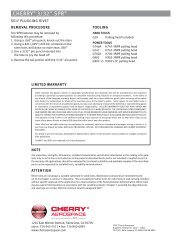
identification material code<br />
(see chart below)<br />
-5 NAS1097 -6, -8 NAS1097<br />
ead Head<br />
CRES C A-286 CRES<br />
M Monel<br />
tion for aluminum<br />
entification on<br />
teners<br />
Head Marking 1<br />
manufacturer’s<br />
identification<br />
CHERRYloCk ® <strong>PRoCEss</strong> <strong>Manual</strong><br />
NOT TO<br />
EXCEED<br />
“D” DIA.<br />
D dia.<br />
A dia<br />
theor.<br />
.006<br />
alum.<br />
.002<br />
.005<br />
Monel<br />
.015<br />
grip BK<br />
Z<br />
Head diameters are to theoretical sharp corners<br />
as measured by projection.<br />
100°±1½° for Monel and A-286<br />
100°±1°<br />
Sheet thickness<br />
shall not be le<br />
K max.<br />
L max.<br />
B<br />
R.010<br />
max.<br />
Min. blind<br />
for satisfactor<br />
installation.<br />
Rivet hea<br />
above<br />
insta<br />
NOT<br />
EXCEE<br />
“D” DIA.
ContEnts<br />
<strong>Cherry</strong>LOCK® Rivet Description .................................... 2<br />
How They Work ............................................................. 3<br />
Selecting the Correct <strong>Cherry</strong>LOCK® Rivet ..................... 5<br />
<strong>Cherry</strong>LOCK® Tools<br />
Hydro-shift System ................................................... 8<br />
Limited Access System ........................................... 11<br />
Gages ..................................................................... 12<br />
Maintenance Items ................................................. 13<br />
Tool Selection Chart .................................................... 14<br />
Hole Preparation ......................................................... 15<br />
<strong>Cherry</strong>LOCK® Installation ........................................... 18<br />
<strong>Cherry</strong>LOCK® Removal ............................................... 22<br />
<strong>Cherry</strong>LOCK® Inspection ............................................ 23<br />
Troubleshooting .......................................................... 25<br />
Proper Sealant Application ......................................... 27<br />
Conversion Table, NAS to <strong>Cherry</strong>LOCK® Numbers ...... 28<br />
Decimal Equivalent Chart ............................................ 30<br />
Warranty ..................................................................... 31<br />
attEntIon: Blind fasteners are not always interchangeable with<br />
non-blind fasteners. Consult with the aircraft Original<br />
Equipment Manufacturer for proper application of<br />
this product.
<strong>CHERRYloCk®</strong> RIvEts<br />
BulBED <strong>CHERRYloCk®</strong> RIvEts<br />
The large blind head of this fastener<br />
introduced the word “bulb” to blind rivet<br />
terminology. Bulbed <strong>Cherry</strong>LOCK® rivets<br />
are locked spindle and flush fracturing<br />
structural rivets. They conform to Procurement<br />
Specifications NAS174O and Standards Pages<br />
NAS1738 and NAS1739. Bulbed <strong>Cherry</strong>LOCK®<br />
rivets can be utilized in both thick and thin<br />
sheet applications.<br />
Typical Maximum Grip<br />
Application<br />
<strong>CHERRYloCk®</strong> WIREDRaW RIvEts<br />
Provides a wide range of sizes, materials and<br />
strength levels.<br />
They conform to Procurement Specification<br />
NAS1400 and Standards Pages NAS1398 and<br />
NAS1399.<br />
<strong>Cherry</strong>LOCK® wiredraw rivets are also<br />
known as “<strong>Cherry</strong>LOCK®” or “Standard<br />
<strong>Cherry</strong>LOCK®”.<br />
Typical Maximum Grip<br />
Application<br />
Both the standard and bulbed <strong>Cherry</strong>loCk® rivets offer important features desired in<br />
an aircraft blind rivet.<br />
• Mechanically locked stem–assured reliability, no lost stems<br />
• Wide grip range–a full 1/16"<br />
• Self-inspecting–if it looks right, it is right<br />
• Positive hole fill–increased joint strength<br />
•High sheet clamp-up–increased fatigue strength<br />
• Excellent head seating–fewer rejections<br />
• Genuine flush fracturing spindle–no shaving, as with other “flushbreak rivets”,<br />
even in thin sheets<br />
• Head marking–grip, materials and manufacturer’s symbol–provides identification<br />
for ready inspection<br />
• All fasteners should be specified and used in accordance with manufacturer’s<br />
recommendations, using the grip range and hole size information provided in this manual.<br />
2
HoW tHEY WoRk<br />
BulBED <strong>CHERRYloCk®</strong> RIvEts<br />
1. Before<br />
pulling<br />
begins.<br />
3. Clamp-up<br />
completed as<br />
stem continues<br />
to bulb out<br />
blind head.<br />
rivet<br />
head<br />
sheet<br />
gap<br />
rivet<br />
sleeve<br />
5. Shear ring has<br />
moved down stem<br />
cone until pulling<br />
head automatically<br />
stops stem<br />
break notch flush<br />
with top of rivet<br />
head.<br />
Locking collar<br />
is now ready<br />
to be inserted.<br />
stem<br />
locking<br />
collar<br />
shear<br />
ring<br />
rivet head<br />
firmly seated<br />
2. Stem is pulled into<br />
rivet sleeve and<br />
starts to form<br />
bulbed blind head.<br />
Clamp-up and<br />
hole fill action<br />
begin.<br />
4. Formation of blind<br />
head and hole<br />
filling are<br />
completed.<br />
Shear ring now<br />
begins to shear<br />
from stem cone<br />
to allow stem<br />
to pull further<br />
into rivet.<br />
Shear<br />
Ring<br />
Note: In minimum grip, shear ring may not shear<br />
6. Completely installed bulbed<br />
<strong>Cherry</strong>LOCK® rivet<br />
Pulling head has inserted<br />
locking collar and stem has<br />
fractured flush with rivet head.<br />
(maximum grip illustrated)<br />
3
HoW tHEY WoRk<br />
WIREDRaW <strong>CHERRYloCk®</strong> RIvEts<br />
4<br />
1. Before pulling<br />
begins<br />
sheet gap<br />
rivet<br />
head<br />
rivet sleeve<br />
3. Blind head<br />
clamps sheets<br />
together<br />
5. Hole fill is completed and<br />
pulling head automatically<br />
stops stem with break notch<br />
flush with rivet head<br />
Locking collar is<br />
now ready to<br />
be inserted<br />
stem<br />
locking<br />
collar<br />
2. Pulling head pulls stem<br />
in and blind head forms<br />
against blind sheet<br />
4. Stem begins to<br />
draw and fill hole<br />
6. Completely installed<br />
<strong>Cherry</strong>LOCK®pulling head has inserted<br />
locking collar and stem has fractured<br />
flush with rivet head
sElECtInG tHE RIvEt<br />
<strong>CHERRYloCk®</strong> anD BulBED <strong>CHERRYloCk®</strong><br />
Wiredraw <strong>Cherry</strong>LOCK® and bulbed <strong>Cherry</strong>LOCK® rivets should be used as a complete fastening<br />
system so that the best features of each can be utilized for optimum strength and performance.<br />
Bulbed <strong>Cherry</strong>LOCK® is a complete shear fastening system. Its features can be utilized for<br />
optimum strength and performance in both thick and thin sheet. It provides the highest possible<br />
design integrity, particularly in double dimple or high vibration areas.<br />
The large blind head of<br />
the bulbed <strong>Cherry</strong>LOCK®<br />
is of particular advantage<br />
in thin blind side sheets<br />
where sheet bearing failure<br />
under load is a problem,<br />
especially in applications<br />
Rivet<br />
Diameter<br />
aluminum Blind<br />
sheet thickness<br />
titanium Blind<br />
sheet thickness<br />
1/8" .040 .020<br />
5/32" .040 .032<br />
3/16" .050 .032<br />
Blind Sheet<br />
(Substructure)<br />
where the blind sheet is equal to or less than the thickness shown in this table:<br />
The wiredraw <strong>Cherry</strong>LOCK® system with its wider range of sizes and materials is especially<br />
suitable for applications unsuitable for bulbed <strong>Cherry</strong>LOCK® rivets. Not recommended for double<br />
dimple.<br />
MInIMuM BlInD sIDE MatERIal Data<br />
The wiredrawing type rivet is designed to give the best hole filling of any blind rivet and<br />
as such must be limited to applications<br />
Blind side<br />
where the blind side substructure has<br />
Material<br />
sufficient bearing strength to withstand the<br />
wiredrawing installation loads. When blind<br />
side substructure is made up of thin or soft<br />
material, then the bulb type rivet would be the<br />
recommended rivet selection.<br />
Wiredrawing type rivets are not recommended<br />
for double dimple applications.<br />
Listed are the recommended rivet selection<br />
material types and minimum thicknesses for<br />
use with the wiredrawing type blind rivets.<br />
Rivet Material<br />
Aluminum<br />
Monel &<br />
A-286 CRES<br />
Rivet<br />
Diameter<br />
-4<br />
-5<br />
-6<br />
-8<br />
-4<br />
-5<br />
-6<br />
-8<br />
thickness<br />
(min)<br />
.030<br />
.040<br />
.050<br />
.060<br />
.040<br />
.050<br />
.060<br />
.080<br />
Blind side<br />
Material<br />
2024<br />
Aluminum<br />
or stronger<br />
7075<br />
Aluminum<br />
or stronger<br />
5
sElECtInG tHE RIvEt<br />
HEaD stYlEs<br />
<strong>Cherry</strong>LOCK® rivets are made in several standard head styles as listed below.<br />
unIvERsal nasM20470<br />
6<br />
<br />
<br />
<br />
For protruding head applications.<br />
Available in both <strong>Cherry</strong>LOCK®<br />
and bulbed <strong>Cherry</strong>LOCK®.<br />
Requires H681-( )C series pulling<br />
head.<br />
<br />
<br />
100° CountERsunk nasM20426<br />
For countersunk applications.<br />
Available in both <strong>Cherry</strong>LOCK®<br />
and bulbed <strong>Cherry</strong>LOCK®.<br />
Requires H681-( )C series pulling<br />
head.<br />
100° CountERsunk nas1097<br />
<br />
<br />
<br />
<br />
<br />
<br />
<br />
For thin top sheet machinecountersunk<br />
applications.<br />
Available in <strong>Cherry</strong>LOCK® only.<br />
Requires H681-( )S series pulling<br />
head.<br />
<br />
<br />
156° CountERsunk<br />
unIsInk<br />
A large diameter, shallow<br />
countersunk head providing wide<br />
bearing area for honeycomb<br />
applications. Available in bulbed<br />
<strong>Cherry</strong>LOCK® only.<br />
Requires H681-( )F series pulling<br />
head.<br />
A combination countersunk and protruding<br />
head for use in very thin top<br />
sheets. Strength equal to double-dimpling<br />
without the high cost. Available<br />
in bulbed <strong>Cherry</strong>LOCK® only.<br />
Requires H681B166-( ) series pulling<br />
head.
sElECtInG tHE RIvEt<br />
DIaMEtERs<br />
The shank diameter of <strong>Cherry</strong>LOCK® rivets is<br />
measured in 32nds of an inch and is identified<br />
by the first dash number;<br />
3/32 dia = (-3), 1/8 dia = (-4), etc.<br />
<strong>Cherry</strong>loCk® Bulbed <strong>Cherry</strong>loCk®<br />
3/32" (-3)* — —<br />
1/8" (-4) 1/8" (-4)<br />
5/32" (-5) 5/32" (-5)<br />
3/16" (-6) 3/16" (-6)<br />
1/4" (-8) — —<br />
*Available in A286 rivets only.<br />
Wiredraw <strong>Cherry</strong>LOCK® is nominal diameter only.<br />
note: Bulbed <strong>Cherry</strong>LOCK® rivet<br />
sleeve is 1/64" oversize only.<br />
GRIP lEnGtH<br />
Grip length refers to the maximum total sheet<br />
thickness to be riveted and is measured in<br />
l6ths of an inch. This is identified by the<br />
second dash number. All <strong>Cherry</strong>LOCK®<br />
rivets, unless otherwise noted, have their<br />
grip length (max. grip) marked on the<br />
rivet head and have a total grip range of<br />
1/16 of an inch (example: -04 grip rivet<br />
has a grip range of .188" to .250").<br />
To determine the proper grip rivet to use,<br />
measure the material thickness with a 269C3<br />
<strong>Cherry</strong>® selector gage as shown below.<br />
Always read to the next higher number.<br />
READ READ RIVET GRIP<br />
NUMBER TO<br />
BE USED: –04<br />
To find the rivet grip number, determine the<br />
total thickness of the material to be fastened.<br />
Locate this amount between minimum and<br />
maximum columns on material thickness<br />
chart below.<br />
Material thickness Range Rivet Grip<br />
Min. Max.<br />
no.<br />
See Stds. pages 1/16" 01<br />
See Stds. pages 1/8" 02<br />
1/8" 3 16" 03<br />
3/16" 1/4" 04<br />
1/4" 5/16" 05<br />
5/16" 3/8" 06<br />
3/8" 7/16" 07<br />
7/16" 1/2" 08<br />
1/2" 9/16" 09<br />
9/16" 5/8" 10<br />
5/8" 11/16" 11<br />
11/16" 3/4" 12<br />
3/4" 13/16" 13<br />
13/16" 7/8" 14<br />
7/8" 15/16" 15<br />
15/16" 1" 16<br />
note: For double dimpled sheets, add countersunk<br />
rivet head height to material thickness.<br />
Csk Bulbed <strong>Cherry</strong>loCk®<br />
Rivet Diameter Head Height<br />
1/8" .035<br />
5/32" .047<br />
3/16" .063<br />
7
CHERRYloCk ® tools<br />
<strong>CHERRYloCk®</strong> HYDRo-sHIft sYstEM<br />
8<br />
G700* G784* G689** G686B-s**<br />
The <strong>Cherry</strong>LOCK® hydro-shift tooling system is an advanced design in which the sequence of<br />
operations necessary to install the rivet is accomplished hydraulically within the hydro-shift tool<br />
rather than by means of a mechanical pulling head.<br />
See the tool selection chart on page 14 of this manual for the capacity of each of these hydroshift<br />
tools.<br />
* Capable of installing rivet group A only<br />
** Capable of installing rivet group A, B and C<br />
H681 PullInG HEaDs<br />
Attach directly to hydro-shift tools G700, G784, G689 and G686B-s.
CHERRYloCk ® tools<br />
sElECtIon of PRoPER HYDRo-sHIft PullInG HEaD<br />
H681 sERIEs<br />
A separate pulling head is required for each diameter <strong>Cherry</strong>LOCK® rivet. It is acceptable that<br />
countersunk (C) pulling heads be used for installing both universal and countersunk head<br />
<strong>Cherry</strong>LOCK® rivets. These heads fit directly on all <strong>Cherry</strong>® hydro-shift riveters.<br />
A<br />
B<br />
2-9/16"<br />
.600" 25/32"<br />
Rivet Dia. Pulling Head number<br />
3/32" H681-3C Universal Head<br />
Countersunk Head (NASM20426)<br />
1/8" H681-4C Universal Head<br />
Countersunk Head (NASM20426)<br />
Dim.<br />
a B<br />
.163 .332<br />
.208 .341<br />
H681-4F Countersunk Head (156°) .430 .358<br />
H681 -4S Countersunk Head (NAS1097) .174 .341<br />
H681B166-4 Unisink Head .250 .359<br />
5/32" H681-5C Universal Head<br />
Countersunk Head (NASM20426)<br />
.269 .352<br />
H681-5F Countersunk Head (156°) .535 .338<br />
H681-5S Countersunk Head (NAS1097) .225 .352<br />
H681B166-5 Unisink Head .313 .377<br />
3/16" H681-6C Universal Head<br />
Countersunk Head (NASM20426)<br />
.335 .386<br />
H681-6F Countersunk Head (156°) .625 .367<br />
H681-6S Countersunk Head (NAS1097) .281 .386<br />
H681B166-6 Unisink Head .375 .419<br />
1/4" H681-8C Universal Head<br />
Countersunk Head (NASM20426)<br />
.458 .398<br />
H681-8S Countersunk Head (NAS1097) .274 .398<br />
9
CHERRYloCk ® tools<br />
sElECtIon of PRoPER HYDRo-sHIft PullInG HEaD<br />
InstallInG H681 PullInG HEaD on RIvEtER<br />
Remove knurled cap a from front of riveter head.<br />
Place jaw assembly D inside collet C.<br />
Insert spring end of jaw assembly into hole in head piston E. Apply enough pressure to engage<br />
collet threads. Turn until collet bottoms on shoulder of piston and collet lock snaps into slot in<br />
piston. Hand tightening is sufficient. note: To remove collet, push collet lock back into collet<br />
(using a blunt pointed tool) while turning the collet counterclockwise.<br />
Place sleeve assembly B over collet and head piston. Slip knurled cap a over the sleeve<br />
assembly and hand tighten onto end of riveter head.<br />
notE: Hydro-shift riveters are factory adjusted to break rivet stem flush and set collar properly.<br />
Fine adjustments to the shift point setting can be made by the operator. This adjustment<br />
determines the flushness of break of the rivet stem and may be accomplished as follows:<br />
Make sure the riveter is connected to air supply.<br />
With trigger released, turn adjuster knob clockwise to lower stem break and counter-clockwise<br />
to raise stem break. Always release tool trigger before turning knob.<br />
A limit pin restricts adjustment to one-half turn of knob either<br />
direction from factory setting. Do not remove this limit pin.<br />
If more than one-half turn adjustment is required to achieve<br />
flush stem break, tool should be returned to your Tool<br />
Maintenance Department for checking with 680A159 gage.<br />
See page 12.<br />
10
CHERRYloCk ® tools<br />
lIMItED aCCEss aPPlICatIons<br />
G695B RIGHt anGlE RIvEtER<br />
The <strong>Cherry</strong>® G695B right angle riveter is a tool designed specifically for installing <strong>Cherry</strong>LOCK®<br />
rivets in limited access areas.<br />
The power unit rests on the floor and is connected to the right angle unit with 8 feet of hose<br />
which further increases the flexibility of this tool. It will install most <strong>Cherry</strong>LOCK® rivets up to a<br />
quarter-inch grip length and most bulbed <strong>Cherry</strong>LOCK® rivets regardless of grip.<br />
H690 series pulling heads fit directly on the above tools. A separate pulling head is required to<br />
install each diameter and head style <strong>Cherry</strong>LOCK® rivet as shown in adjoining table.<br />
<br />
1-1/2"<br />
<br />
<br />
15/16"<br />
<br />
<br />
9/16"<br />
<br />
Standard Head is<br />
nominally flush with<br />
bottom of riveter<br />
G695B Right Angle Riveter<br />
Rivet<br />
Diameter<br />
1/8"<br />
5/32"<br />
3/16"<br />
1/4"<br />
standard<br />
Pulling Head number<br />
H690-4U Universal Head<br />
H690-4C Countersunk Head<br />
H690-5U Universal Head<br />
H690-5C Countersunk Head<br />
H690-6U Universal Head<br />
H690-6C Countersunk Head<br />
H690-8U Universal Head<br />
H690-8C Countersunk Head<br />
note: These pulling heads are also available in<br />
9/16", 15/16" and 1-1/2" extensions. To order,<br />
specify proper pulling head and add length of<br />
extension to part number (e.g. H690-4U-15/16").<br />
This tool installs all bulbed <strong>Cherry</strong>LOCK® rivets and<br />
installs up to -04 grip wiredraw <strong>Cherry</strong>LOCK® rivets.<br />
11
CHERRYloCk ® tools<br />
GaGEs<br />
269C3 GRIP GaGE<br />
A simple, self-explanatory gage for determining material<br />
thickness and proper rivet grip length.<br />
t172 RIvEt HolE sIZE GaGE<br />
These are precision ground, go no-go gages used to check<br />
holes drilled for <strong>Cherry</strong>® blind rivets. They are made in all<br />
standard rivet diameters plus the oversize rivet diameters.<br />
628 sEttInG GaGEs<br />
These gages are used to adjust the shift point and lock ring<br />
anvil settings on <strong>Cherry</strong>LOCK® mechanical pulling heads<br />
H615B, H640B, H642 and H690. A separate gage is required<br />
for each rivet diameter and the correct gage is furnished with<br />
each new pulling head along with instructions for its use.<br />
680a159 sEttInG GaGE<br />
This gage is used to adjust the shift point setting on <strong>Cherry</strong>®<br />
hydro-shift riveters. One of these gages is furnished with each<br />
new hydro-shift riveter, along with instructions for its use.<br />
anvIl GaGEs<br />
These go no-go gages are used to check the hole diameters<br />
of lock ring anvils in all <strong>Cherry</strong>LOCK® pulling heads H681<br />
and H690. Their use will help eliminate installation problems<br />
caused by worn, oversized anvils. A separate gage is required<br />
for each rivet diameter.<br />
12<br />
Rivet<br />
Diameter<br />
Hole Gage Part numbers<br />
standard Bulbed<br />
3/32" T172-3 —<br />
1/8" T172-4 T172-400<br />
5/32" T172-5 T172-500<br />
3/16" T172-6 T172-600<br />
1/4" T172-8 —<br />
Rivet Dia. Gage no.<br />
1/8" 628-4 (green)<br />
5/32" 628-5 (red)<br />
3/16" 628-6 (blue)<br />
1/4" 628-8 (aluminum)<br />
Rivet Dia. Gage no.<br />
3/32" P913<br />
1/8" P856<br />
5/32" P857<br />
3/16" P858<br />
1/4" P859
CHERRYloCk ® tools<br />
MaIntEnanCE ItEMs<br />
700a77 aIR BlEEDER<br />
To keep <strong>Cherry</strong>® rivet hydraulic tools operating at peak efficiency, it is<br />
absolutely essential that the hydraulic systems be kept full of fluid and<br />
free of air.<br />
Based on the same principle used in bleeding the hydraulic brake system<br />
of an automobile, the 700A77 <strong>Cherry</strong>® air bleeder will quickly and easily<br />
remove all air and assure the complete filling of the tool with Dexron III<br />
automatic transmission fluid. It may be used in the tool crib or right on<br />
the production line, since it requires but a few minutes to perform this<br />
vital function. The air bleeder is a small item, but it does a really big job: it<br />
prevents downtime.<br />
sERvICE kIts<br />
An assortment of O-rings, seals, screws, washers and gaskets is available<br />
in kit form for each <strong>Cherry</strong>® power tool. To avoid unnecessary downtime, it<br />
is advisable to have these kits on hand for the tools being serviced.<br />
<strong>Cherry</strong>® tool service kit no.<br />
G685B-S & G686B-S G685-S/686-SKS<br />
G689 G689KS<br />
G695B G695KS<br />
G700 G700KS<br />
G715A G715KS<br />
G740A G740KS<br />
G784 G784KS<br />
13
sElECtInG CHERRYloCk ® tools<br />
The numbers shown in the rivet columns below are the maximum grip length that can be<br />
installed with these tools.<br />
14<br />
tool<br />
Model<br />
Pulling<br />
Head<br />
G700 H681<br />
G784 H681<br />
G686B-S H681<br />
G689 H681<br />
G695B H690<br />
Rivet<br />
Dia.<br />
Bulbed <strong>Cherry</strong>loCk®<br />
nas1738 & nas1739<br />
aluminum<br />
2235<br />
2239<br />
2245<br />
2249<br />
2238<br />
2248<br />
2539<br />
2545<br />
2839<br />
2845<br />
standard <strong>Cherry</strong>loCk®<br />
nas1398 & nas1399<br />
Monel &<br />
Inconel aluminum Monel CREs Inconel<br />
2538<br />
2540<br />
2838<br />
2840<br />
2163<br />
2263<br />
2162<br />
2164<br />
2262<br />
2264 2563<br />
2562<br />
2564<br />
2643<br />
2653<br />
2663<br />
2<br />
2642<br />
2652<br />
2662<br />
2664<br />
2<br />
univ. Ctsk. univ. Ctsk. univ. Ctsk. univ. Ctsk. univ. Ctsk.<br />
-3 NA NA NA NA NA NA NA NA ALL ALL<br />
-4 ALL ALL ALL ALL 8 9 8 9 8 9<br />
-5 — — — — — — — — — —<br />
-6 — — — — — — — — — —<br />
-8 NA NA NA NA — — — — — —<br />
-3 NA NA NA NA NA NA NA NA ALL ALL<br />
-4 ALL ALL ALL ALL ALL ALL ALL ALL ALL ALL<br />
-5 ALL ALL ALL ALL 8 9 8 9 8 9<br />
-6 ALL ALL ALL 1 ALL 1 8 9 8 9 81 91 -8 NA NA NA NA — — — — — —<br />
-4 ALL ALL ALL ALL ALL ALL ALL ALL ALL ALL<br />
-5 ALL ALL ALL ALL ALL ALL ALL ALL ALL ALL<br />
-6 ALL ALL ALL ALL ALL ALL ALL ALL ALL ALL<br />
-8 NA NA NA NA ALL ALL ALL ALL — —<br />
-4 ALL ALL ALL ALL ALL ALL ALL ALL ALL ALL<br />
-5 ALL ALL ALL ALL ALL ALL ALL ALL ALL ALL<br />
-6 ALL ALL ALL ALL ALL ALL ALL ALL ALL ALL<br />
-8 NA NA NA NA ALL ALL ALL ALL ALL ALL<br />
-4 ALL ALL ALL ALL 4 4 4 4 4 4<br />
-5 ALL ALL ALL ALL 4 4 4 4 4 4<br />
-6 — — — — 4 4 4 4 — —<br />
-8 NA NA NA NA 4 4 — — — —<br />
1 May require 95 PSI air pressure at tool<br />
2 3/32" A-286 (CR2662 & CR2663) rivets may be installed with any <strong>Cherry</strong>® hydro-shift riveter<br />
— indicates rivet sizes which cannot be installed in any grip length
HolE PREPaRatIon<br />
Proper hole preparation is very important in obtaining a strong, rigid, and reliable<br />
blind riveted joint.<br />
HolE sIZE<br />
<strong>Cherry</strong>LOCK® rivets are designed to function<br />
within a specified hole range. The hole size<br />
limits, along with suggested drill sizes, are<br />
listed below.<br />
Recommended Drill sizes, Hole size and Countersunk Diameter limits<br />
Rivet<br />
Dia.<br />
<strong>Cherry</strong>loCk® Bulbed <strong>Cherry</strong>loCk®<br />
Drill<br />
size Min. Max.<br />
Drill<br />
size Min. Max.<br />
100° nasM20426<br />
Head<br />
C<br />
Max.<br />
C<br />
Min.<br />
100° nas1097<br />
Head 100° unisink Head<br />
C<br />
Max.<br />
C<br />
Min.<br />
C<br />
Max.<br />
3/32" #40 .097 .100 — — — .182 .176 — — — —<br />
1/8" #30 .129 .132 #27 .143 .146 .228 .222 .195 .189 .173 .167<br />
5/32" #20 .160 .164 #16 .176 .180 .289 .283 .246 .240 .216 .210<br />
3/16" #10 .192 .196 #5 .205 .209 .356 .350 .302 .296 .258 .252<br />
1/4" F .256 .261 — — — .479 .473 .395 .389 — —<br />
The above drill sizes are those which normally produce holes within the specified limits. Holes<br />
should be checked with a <strong>Cherry</strong>® go no-go gage to assure drilling accuracy.<br />
GO NO-GO<br />
Rivet<br />
Diameter<br />
100°<br />
C<br />
.010" R Max<br />
Aluminum<br />
.020" R Max.<br />
Monel & A-286<br />
Hole Gage Part numbers<br />
standard Bulbed<br />
3/32" T172-3 —<br />
C<br />
Min.<br />
1/8" T172-4 T172-400<br />
5/32" T172-5 T172-500<br />
3/16" T172-6 T172-600<br />
1/4" T172-8 —<br />
15
HolE PREPaRatIon<br />
DRIllInG PRoCEDuRE<br />
Use a clean, sharp, properly ground drill. Improperly<br />
ground drills will create oval or oversize holes.<br />
Center the drill in the chuck so that the drill will run<br />
true. A “wobble” in the drill will create an oversize hole.<br />
Hold the drill perpendicular to the surface being drilled.<br />
Do not force the drill through the material.<br />
To insure proper hole alignment and to prevent burrs<br />
and chips from lodging between the sheets, the<br />
materials to be riveted should be clamped tightly<br />
together.<br />
Tack rivets or clamps should be used to prevent material<br />
creep and hole misalignment during the drilling<br />
operation.<br />
16<br />
Improperly<br />
Ground<br />
Properly<br />
Ground<br />
RIGHT 90° WRONG<br />
RIGHT springloaded<br />
fastener<br />
WRONG<br />
chips<br />
drill “wobble”<br />
clean<br />
hole<br />
misalignment<br />
tack<br />
rivet
HolE PREPaRatIon<br />
CountERsInkInG<br />
Accurate countersinking is of primary importance to<br />
the structural integrity of a flush riveted joint. Standard<br />
countersinking procedures as used with solid rivets are<br />
also applicable to <strong>Cherry</strong>LOCK® rivets. The following<br />
points, however, should be carefully noted:<br />
The countersink pilot should be no more than .001"<br />
smaller than the hole diameter. A greatly undersized<br />
pilot will produce a countersink which is not<br />
concentric with the hole, creating head gap problems.<br />
An countersink pilot which is too small also creates<br />
a countersink whose axis is not in line with the axis<br />
of the drilled hole. This will result in a “cocked”<br />
rivet head.<br />
DIMPlInG<br />
Normal dimpling procedures stretch and enlarge the<br />
pilot holes in thin sheet applications. The sheets (as<br />
dimpled) provide only sharp edges within the hole.<br />
To overcome the problems inherent in this type of<br />
application, the dimple should first be prepared with a<br />
hole size which will allow for subsequent reaming.<br />
The hole should then be reamed to the dimensions<br />
specified for the size rivet being installed. The bulbed<br />
<strong>Cherry</strong>LOCK® is especially recommended for this<br />
application.<br />
sharp<br />
edges<br />
smooth<br />
hole<br />
cocked head<br />
gap<br />
17
CHERRYloCk ® InstallatIon<br />
DE-BuRRInG<br />
All drilling operations cause burrs to<br />
form on each end of the hole being<br />
drilled, as well as between the<br />
sheets. Whenever possible, all burrs<br />
should be removed.<br />
When using a drill or center reamer<br />
to remove burrs, care must be taken<br />
to remove onlY the burr. Do not<br />
chamfer the sheets, as this may<br />
materially affect the strength of<br />
the riveted joint, particularly with<br />
respect to the blind sheet.<br />
18<br />
burr<br />
remove chips<br />
remove burrs<br />
burr<br />
Poor<br />
Good
CHERRYloCk ® InstallatIon<br />
RIvEt GRIP sElECtIon<br />
<br />
<br />
<br />
<br />
<br />
<br />
<br />
<br />
269C3 GRIP GaGE<br />
To determine the proper grip rivet to use, measure the material thickness with a 269C3 grip gage<br />
as shown below.<br />
Insert the grip gage into the prepared hole, draw gage back until lip contacts backside of<br />
structure and read where front side of structure coincides with numbers and lines on gage.<br />
Always read to the next higher number (if reading is directly on a line you may use either that<br />
grip or the next higher one).<br />
.062<br />
.094<br />
.125<br />
.250<br />
.032<br />
READ<br />
.125<br />
READ<br />
PRotRuDInG HEaD<br />
Correct rivet grip is a -02, since grip range of a -02 rivet<br />
is .062 to .125.<br />
MaCHInE CountERsunk<br />
Read correct rivet grip to top of sheet. Since this<br />
example is on the line use either -04 or -05 grip.<br />
DouBlE DIMPlE<br />
Read correct rivet grip to top of sheet. Grip is sheet<br />
thickness plus rivet head height. This example would<br />
require a -05 grip.<br />
<br />
19
CHERRYloCk ® InstallatIon<br />
PlaCInG RIvEt In HolE<br />
Select the proper pulling head to conform to the<br />
diameter and head style of <strong>Cherry</strong>LOCK® rivet being<br />
installed. The rivet is now ready to be placed in the hole.<br />
The holes in the sheets to be fastened must be of<br />
correct size and aligned properly. Do not force the rivet<br />
into the hole.<br />
In limited blind clearance applications, the<br />
manufactured head of the standard <strong>Cherry</strong>LOCK® rivet<br />
can protrude above the top sheet and will pull down to<br />
the sheet as the stem is pulled in. The minimum blind<br />
clearance is the “BK” dimension; this is listed on our<br />
Standards Pages.<br />
Right Wrong<br />
PlaCInG PullInG HEaD on RIvEt stEM<br />
Hold the riveter and pulling head in line with the axis of<br />
the rivet, while holding the riveter in a light and flexible<br />
manner.<br />
notE: <strong>Cherry</strong>LOCK® wiredraw rivets require longer<br />
stroke installation tools than the <strong>Cherry</strong>LOCK® bulbed<br />
rivet.<br />
Stroke requirements increase with the increase in grip<br />
length.<br />
There are three groups (or stroke settings) for <strong>Cherry</strong>LOCK® wiredraw rivets. These are<br />
identified in the <strong>Cherry</strong>LOCK® catalog under each wiredraw part number. See “Rivet Group” in<br />
the <strong>Cherry</strong>LOCK® wiredraw portion of the catalog for stroke limits.<br />
20<br />
Right Wrong<br />
misaligned<br />
hole<br />
obstruction
CHERRYloCk ® InstallatIon<br />
When installing <strong>Cherry</strong>LOCK ® rivets, hold the riveter in<br />
line with the rivet as accurately as possible, and, applying<br />
a steady but light pressure, pull the trigger and let the<br />
rivet do the work.<br />
aCtuatInG RIvEtER<br />
The pulling head will pull down and seat against the<br />
rivet head.<br />
The rivet clamping action will pull the sheets together<br />
and seat the rivet head.<br />
The action of the rivet will automatically help to bring<br />
the riveter and pulling head into proper alignment with<br />
the rivet axis.<br />
Pressing down with force will not allow the rivet and the<br />
riveter to align themselves with the hole, and this may<br />
limit the head seating action of the rivet.<br />
When the rivet is completely installed, release the<br />
trigger and the pulling head will automatically eject<br />
the pulling portion of the stem through the front end.<br />
Controlled stem release into receptacle will control<br />
F.O.D. problems.<br />
RIvEt sHavInG<br />
Normal shop practice will result in countersunk rivets<br />
which are essentially flush with the aircraft skin. Further<br />
secondary operations are not normally necessary.<br />
When perfect aerodynamic flushness is required,<br />
the sheet should be countersunk so that the rivet<br />
heads protrude and subsequent shaving will produce<br />
complete aerodynamic flushness. The table on the right<br />
shows the recommended countersink diameter to be<br />
used for shaving.<br />
When rivets are to be shaved for aerodynamic<br />
flushness, care should be taken to assure the pulling<br />
head is properly adjusted so that a flush stem fracture<br />
will occur within the limits shown on page 23, to insure<br />
that any reduction in spindle retention due to shaving<br />
will be held to a minimum and within safety limits.<br />
Before<br />
Shaving<br />
ejected stem<br />
NASM20426 head only.<br />
Rivet<br />
Dia.<br />
Recommended<br />
Countersink<br />
Dia. +.005 -.000<br />
pulling head<br />
flush break<br />
After<br />
Shaving<br />
approx.<br />
Protrusion of<br />
Rivet Head<br />
above sheet<br />
1/8" .214" .005"<br />
5/32" .274" .005"<br />
3/16" .339" .005"<br />
1/4" .461" .005"<br />
Values are for 100°<br />
21
RIvEt REMoval<br />
Should it be necessary to remove an installed<br />
<strong>Cherry</strong>LOCK® rivet, the following procedures<br />
are recommended:<br />
1. In thick material remove the lock by driving<br />
out the rivet stem, using a pin punch.<br />
2. If the rivets have been<br />
installed in thin sheets,<br />
driving out the locked stem<br />
may damage the sheets. It is<br />
recommended that the stem<br />
be center punched first and a<br />
small center drill be used to<br />
provide a guide for a larger drill on top of the<br />
rivet stem. The larger drill can then be used to<br />
drill away the lock. Finally, use a pin punch to<br />
drive out the stem.<br />
3. Drill nearly through the head of the<br />
rivet, using a drill the same size as the<br />
rivet shank. Do not drill completely<br />
through rivet head.<br />
4. Break off rivet head, using a pin punch<br />
as a pry.<br />
5. Drive out the remaining rivet shank<br />
with a pin punch having a diameter equal<br />
to the rivet shank.<br />
CautIon: Never drill completely through the<br />
rivet sleeve to remove a rivet as this will tend<br />
to enlarge the hole.<br />
22
CHERRYloCk ® InsPECtIon<br />
Inspection for the proper installation of <strong>Cherry</strong>LOCK® rivets can be made from the visible<br />
side of the work.<br />
stEM anD CollaR flusHnEss<br />
If the rivet stem and collar are flush within the<br />
limits described it can be safely concluded that<br />
a satisfactory blind head and lock has been<br />
formed.<br />
Rivet<br />
size<br />
-3<br />
Dia.<br />
-4<br />
Dia.<br />
-5<br />
Dia.<br />
-6<br />
Dia.<br />
-8<br />
Dia.<br />
A max. .015 .015 .020 .025 .030<br />
B max. .010 .010 .010 .015 .020<br />
Inspect installed rivet flushness to break-off<br />
limits of NAS1400 and NAS1740<br />
A = Collar above breaknotch of stem<br />
B = Collar above top of rivet head<br />
A slight collar “flash” caused by the pressures<br />
necessary to drive the collar is acceptable within<br />
the limit shown.<br />
STEM PROTRUSION LIMITS<br />
COLLAR PROTRUSION LIMITS<br />
COLLAR FLASH<br />
23
CHERRYloCk ® InsPECtIon<br />
GRIP lEnGtH<br />
<strong>Cherry</strong>LOCK® rivets have the grip length marked on the<br />
rivet head (except 3/32" and 1/8" diameter and 5/32"<br />
in NAS1O97 head style) to provide positive inspection<br />
from the visible side to show that the rivets have been<br />
installed with the correct grip.<br />
tYPICal BlInD HEaD<br />
If the grip marking indicates the rivet has been installed<br />
in the proper grip and the stem and collar are flush<br />
within prescribed limits, blind heads typical of those<br />
illustrated will be obtained.<br />
Superficial stretch marks which may appear in the rivet<br />
sleeve are not detrimental to rivet strength and are<br />
acceptable.<br />
24<br />
Aluminum<br />
Monel<br />
Aluminum<br />
Max. Grip Min. Grip<br />
Max. Grip Min. Grip<br />
<strong>Cherry</strong>loCk® Rivets Bulbed <strong>Cherry</strong>loCk® Rivets<br />
Bulbed Blind Head<br />
Monel<br />
Stretch Marks<br />
(acceptable)
tRouBlEsHootInG<br />
The correct installation of <strong>Cherry</strong>LOCK® rivets requires that the instructions contained in this<br />
manual regarding hole preparation, tools and installation technique be carefully followed.<br />
It is imperative that the pulling heads be clean, free from chips, burrs and dry sealant and are in<br />
proper adjustment and mechanical repair.<br />
The following trouble shooting guide will consider several sources for each problem and a<br />
solution for each.<br />
The following problems and solutions apply to both bulbed and <strong>Cherry</strong>LOCK® rivets.<br />
RIvEt stEM Pulls tHRouGH oR BREaks HIGH<br />
Rivet stem break notch pulls to .030” or higher above<br />
rivet head. Stem may or may not break.<br />
souRCE of PRoBlEM<br />
A. Pulling head shifts too late–readjust pulling head to<br />
shift sooner.<br />
B. Rivet installed in oversize hole–drill smaller holes or<br />
use larger diameter rivet.<br />
C. Rivet installed in under minimum grip–use shorter<br />
grip rivet.<br />
RIvEt stEM BREaks loW<br />
Collar does not set: Rivet stem breaks well below rivet head<br />
and collar does not set.<br />
souRCE of PRoBlEM<br />
A. Rivet installed in undersize hole–drill out holes to proper size.<br />
B. Rivet installed in over maximum grip–use longer grip rivet.<br />
C. Holes slanted or misaligned–use more care to obtain holes which are<br />
properly aligned and normal to the sheets.<br />
D. Installer “cocks” pulling head–use more care to align tool and keep arm<br />
flexible to allow rivet to align itself.<br />
Collar does set: Rivet stem breaks below rivet head but collar is set.<br />
souRCE of PRoBlEM<br />
A. Pulling head shifts too soon–use 680A159 to verify stroke setting.<br />
B. Wrong type head–only <strong>Cherry</strong>® tools will install <strong>Cherry</strong>LOCK® rivets.<br />
Do not use other manufacturer’s tooling.<br />
break<br />
notch<br />
Pull-Through Break High<br />
25
tRouBlEsHootInG<br />
loCkInG CollaR DoEs not sEt<br />
Rivet stem breaks near flush but collar does not set.<br />
souRCE of PRoBlEM<br />
A. Rivet installed in over maximum grip–use longer grip<br />
rivet.<br />
B. Chips prevent anvil from setting collar–chips, burrs,<br />
and dry sealant will build up on head anvil and<br />
restrict forward thrust necessary to set collar. Clean<br />
thoroughly and readjust.<br />
C. Rivet installed in undersize hole–drill out hole to<br />
proper size.<br />
D. Pulling head shifts too soon–use 680A159 to verify<br />
stroke setting.<br />
PooR HEaD sEatInG<br />
Rivet head does not seat properly against top sheet or<br />
in countersink.<br />
souRCE of PRoBlEM<br />
A. Holes slanted or misaligned–use more care to obtain<br />
holes which are properly aligned and normal to the<br />
sheets.<br />
B. Countersink not concentric with hole–use countersink<br />
pilot which is close to hole size.<br />
C. Installer “cocks” pulling head and rivet head during<br />
installation. Installer should hold tool and pulling<br />
head in a flexible manner, so rivet can clamp head<br />
down properly.<br />
26<br />
Gap
PRoPER sEalant aPPlICatIon<br />
Blind rivets depend on a balance of lubricity to friction, compression and radial expansion during<br />
installation. In the manufacturing process, lubricants are typically used to ensure the blind rivet<br />
installs correctly.<br />
Sealant should be applied ONLY around the rivet sleeve (see illustration). It is critical that the<br />
sealant does not touch either the lock collar or the plug section of the fastener.<br />
Do not apply<br />
sealant on<br />
these areas<br />
Apply sealant<br />
here only!<br />
When sealant is applied to the fastener incorrectly, two conditions may occur. Either the stem<br />
of the fastener will pull high or all the way through the rivet sleeve, or the stem will break<br />
prematurely and will be too deep in the rivet sleeve to be properly locked by the lock collar. In<br />
either case, the rivet must be removed and replaced. Initial care in the application of sealant will<br />
eliminate this replacement process.<br />
27
ConvERsIon taBlE<br />
nas nuMBERs to CHERRY® RIvEt nuMBERs<br />
A complete conversion table of <strong>Cherry</strong>® rivet numbers is available upon request.<br />
<strong>CHERRYloCk®</strong> RIvEts<br />
28<br />
Head style nas no. <strong>Cherry</strong>® no. Rivet Material stem Material<br />
universal<br />
Head<br />
(NASM20470)<br />
Countersunk<br />
Head<br />
(NASM20426)<br />
Countersunk<br />
Head<br />
(NAS1097)<br />
NAS 1398B<br />
None<br />
None<br />
NAS 1398C<br />
NAS 1398CW<br />
NAS 1398D<br />
NAS 1398M<br />
NAS 1398MS<br />
NAS 1398MW<br />
NAS 1399B<br />
None<br />
None<br />
NAS 1399C<br />
NAS 1399CW<br />
NAS 1399D<br />
NAS 1399M<br />
NAS 1399MS<br />
NAS 1399MW<br />
None<br />
None<br />
None<br />
None<br />
None<br />
CR2263<br />
CR2643*<br />
CR2653<br />
CR2663<br />
CR2663CW<br />
CR2163<br />
CR2563M<br />
CR2563S<br />
CR2563<br />
CR2262<br />
CR2642*<br />
CR2652<br />
CR2662<br />
CR2662CW<br />
CR2162<br />
CR2562M<br />
CR2562S<br />
CR2562<br />
CR2164<br />
CR2564<br />
CR2564M<br />
CR2664<br />
CR2664CW<br />
*95KSI fastener for use in high bearing strength material, steel, CRES, TI, etc.<br />
5056 Aluminum<br />
A286 CRES<br />
A286 CRES<br />
A286 CRES<br />
A286 CRES, Cad. Plt’d.<br />
2017 Aluminum<br />
Monel<br />
Monel, Silver Plt’d.<br />
Monel, Cad. Plt’d.<br />
5056 Aluminum<br />
A286 CRES<br />
A286 CRES<br />
A286 CRES<br />
A286 CRES, Cad. Plt’d.<br />
2017 Aluminum<br />
Monel<br />
Monel, Silver Plt’d.<br />
Monel, Cad. Plt’d.<br />
2017 Aluminum<br />
Monel, Cad. Plt’d.<br />
Monel<br />
A286 CRES<br />
A286 CRES, Cad. Plt’d.<br />
7075 Aluminum<br />
A286 CRES, STA<br />
A286 CRES<br />
A286 CRES<br />
A286 CRES<br />
7075 Aluminum<br />
Monel<br />
Monel<br />
Monel<br />
7075 Aluminum<br />
A286 CRES, STA<br />
A286 CRES<br />
A286 CRES<br />
A286 CRES<br />
7075 Aluminum<br />
Monel<br />
Monel<br />
Monel<br />
7075 Aluminum<br />
Monel<br />
Monel<br />
A286 CRES<br />
A286 CRES
ConvERsIon taBlE<br />
nas nuMBERs to CHERRY RIvEt nuMBERs<br />
A complete conversion table of <strong>Cherry</strong>® rivet numbers is available upon request.<br />
BulBED <strong>CHERRYloCk®</strong> RIvEts<br />
Head style nas no. <strong>Cherry</strong>® no. Rivet Material stem Material<br />
universal Head<br />
(NASM20470)<br />
Countersunk Head<br />
(NASM20426)<br />
NAS 1738B<br />
NAS 1738E<br />
NAS 1738M<br />
NAS 1738MW<br />
NAS 1738C<br />
NAS 1738CW<br />
NAS 1739B<br />
NAS 1739E<br />
NAS 1739M<br />
NAS 1739MW<br />
NAS 1739C<br />
NAS 1739CW<br />
unisink Head —<br />
—<br />
—<br />
—<br />
Countersunk Head (156°) —<br />
—<br />
CR2249<br />
CR2239<br />
CR2539<br />
CR2539P<br />
CR2839<br />
CR2839CW<br />
CR2248<br />
CR2238<br />
CR2538<br />
CR2538P<br />
CR2838<br />
CR2838CW<br />
CR2235<br />
CR2245<br />
CR2545<br />
CR2845<br />
CR2540<br />
CR2840<br />
5056 Aluminum<br />
5056 Aluminum<br />
Monel<br />
Monel, Cad. Plt’d.<br />
Inconel 600<br />
lnconel 600, Cad.<br />
Plt’d.<br />
5056 Aluminum<br />
5056 Aluminum<br />
Monel<br />
Monel, Cad. Plt’d.<br />
Inconel 600<br />
lnconel 600, Cad.<br />
Plt’d.<br />
5056 Aluminum<br />
5056 Aluminum<br />
Monel<br />
Inconel 600<br />
Monel<br />
Inconel 600<br />
Alloy Steel, Cad. Plt’d.<br />
Inconel 600<br />
Inconel 600<br />
Inconel 600<br />
A286 CRES<br />
A286 CRES<br />
Alloy Steel, Cad. Plt’d.<br />
Inconel 600<br />
Inconel 600<br />
Inconel 600<br />
A286 CRES<br />
A286 CRES<br />
Inconel 600<br />
Alloy Steel, Cad. Plt’d.<br />
Inconel 600<br />
A286 CRES<br />
Inconel 600<br />
A286 CRES<br />
29
DECIMal EquIvalEnt CHaRt<br />
Nom. M/M Dec. Nom. M/M Dec. Nom. M/M Dec. Nom. M/M Dec. Nom. M/M Dec.<br />
30<br />
— .1 .0039 1/16 — .0625 21 — .1590 K — .2810 9/16 — .5625<br />
— .2 .0079 52 — .0635 20 — .1610 9/32 — .2812 37/64 — .5781<br />
— .3 .0118 51 — .0670 19 — .1660 L — .2900 — 15.0 5906<br />
80 — .0135 50 — .0700 18 — .1695 M — .2950 19/32 — .5937<br />
79 — .0145 49 — .0730 11/64 — .1719 19/64 — .2969 39/64 — .6094<br />
1/64 — .0156 48 — .0760 17 — .1730 N — .3020 5/8 — .6250<br />
— .4 .0157 5/64 — .0781 16 — .1770 5/16 — .3125 — 16.0 .6299<br />
78 — .0160 47 — .0785 15 — .1800 — 8.0 .3150 41/64 — .6406<br />
77 — .0180 — 2 .0787 14 — .1820 O — .3160 21/32 — .6562<br />
— .5 .0197 46 — .0810 13 — .1850 P — .3230 — 17.0 .6693<br />
76 — .0200 45 — .0820 3/16 — .1875 21/64 — .3281 43/64 — .6719<br />
75 — .0210 44 — .0860 12 — .1890 Q — .3320 11/16 — .6875<br />
74 — .0225 43 — .0890 11 — .1910 R — .3390 14/84 — .7031<br />
— .6 .0236 42 — .0935 10 — .1935 11/32 — .3437 — 18.0 .7087<br />
73 — .0240 3/32 — .0937 9 — .1960 S — .3480 23/32 — .7187<br />
72 — .0250 41 — .0960 — 5.0 .1968 — 9.0 .3543 47/64 — .7344<br />
71 — .0260 40 — .0980 8 — .1990 T — .3580 — 19.0 .7480<br />
— .7 .0276 39 — .0995 7 — .2010 23/64 — .3594 3/4 — .7500<br />
70 — .0280 38 — .1015 13/64 — .2031 U — .3680 49/54 — .7656<br />
69 — .0292 37 — .1040 6 — .2040 3/8 — .3750 25/32 — .7812<br />
68 — .0310 36 — .1065 5 — .2055 V — .3770 — 20.0 .7874<br />
1/32 — .0312 7/64 — .1094 4 — .2090 W — .3860 51/64 — .7969<br />
— .8 .0315 35 — .1100 3 — .2130 25/64 — .3906 13/16 — .8125<br />
67 — .0320 34 — .1110 7/32 — .2187 — 10.0 .3937 — 21.0 .8268<br />
66 — .0330 33 — 1130 2 — .2210 X — .3970 53/64 — .8281<br />
65 — .0350 32 — .1160 1 — .2280 Y — .4040 27/32 — .8437<br />
— .9 .0354 — 3.0 .1181 A — .2340 13/32 — .4062 55/64 — .8594<br />
64 — .0360 31 — .1200 15/64 — .2344 Z — .4130 — 22.0 .8661<br />
63 — .0370 1/8 — .1250 — 6.0 .2362 27/64 — .4219 7/8 — .8750<br />
62 — .0380 30 — .1285 B — .2380 — 11.0 .4331 57/64 — .8906<br />
61 — .0390 29 — .1360 C — .2420 7/16 — .4375 — 23.0 .9055<br />
— 1 .0394 28 — .1405 D — .2460 29/64 — .4531 29/32 — .9062<br />
60 — .0400 9/64 — .1406 1/4 — .2500 15/32 — .4687 59/64 — .9219<br />
59 — .0410 27 — .1440 E — .2500 — 12.0 .4724 15/16 — .9375<br />
58 — .0420 26 — .1470 F — .2570 31/64 — .4844 — 24.0 .9449<br />
57 — .0430 25 — .1495 G — .2610 1/2 — .5000 61/64 — .9531<br />
56 — .0465 24 — .1520 17/64 — .2656 — 13.0 .5118 31/32 — .9687<br />
3/64 — .0469 23 — .1540 H — .2660 33/64 — .5156 — 25.0 .9842<br />
55 — .0520 5/32 — .1562 I — .2720 17/32 — .5312 63/64 — .9844<br />
54 — .0550 22 — .1570 — 7.0 .2756 35/64 — .5469 1 25.4 1.000<br />
53 — .0595 — 4.0 .1575 J — .2770 — 14.0 .5512 — — —
LIMITED WARRANTY<br />
Seller warrants the goods conform to applicable specifications and drawings and will be manufactured and<br />
inspected according to generally accepted practices of companies manufacturing industrial or aerospace<br />
fasteners. In the event of any breach of the foregoing warranty, Buyer’s sole remedy shall be to return defective<br />
goods (after receiving authorization from Seller) for replacement or refund of the purchase price, at the Seller’s<br />
option. Seller agrees to any freight costs in connection with the return of any defective goods, but any costs<br />
relating to removal of the defective or nonconforming goods or installation of replacement goods shall be<br />
Buyer’s responsibility. SELLER’S WARRANTY DOES NOT APPLY WHEN ANY PHYSICAL OR CHEMICAL CHANGE<br />
IN THE FORM OF THE PRODUCT IS MADE BY BUYER. THE FOREGOING EXPRESS WARRANTY AND REMEDY ARE<br />
EXCLUSIVE AND ARE IN LIEU OF ALL OTHER WARRANTIES AND REMEDIES; ANY IMPLIED WARRANTY AS TO<br />
QUALITY, FITNESS FOR PURPOSE, OR MERCHANTABILITY IS HEREBY SPECIFICALLY DISCLAIMED AND EXCLUDED<br />
BY SELLER. This warranty is void if seller is not notified in writing of any rejection of the goods within one (1)<br />
Year aFter initial use by buyer of any power Riveter or ninety (90) days after initial use of any other product.<br />
Seller shall not be liable under any circumstances for incidental, special or consequential damages arising in whole<br />
or in part from any breach by Seller, AND SUCH INCIDENTAL, SPECIAL, OR CONSEQUENTIAL DAMAGES ARE HEREBY<br />
EXPRESSLY EXCLUDED.<br />
Our policy is one of continuous development. Specifications shown in this document may be subject to changes<br />
introduced after publication.<br />
<strong>Cherry</strong>® and <strong>Cherry</strong>LOCK® are trademarks of <strong>Cherry</strong> <strong>Aerospace</strong>.<br />
note<br />
The properties, strengths, dimensions, installed characteristics and all other information in this catalog<br />
is for guidance only to aid in the correct selection of the products described herein and is not intended or<br />
implied as part of the warranty. All applications should be evaluated for functional suitability and available<br />
samples of the described parts can be requested for installed tests, suitability and evaluations.<br />
attention<br />
Blind fasteners are not always a suitable substitute for solid shank fasteners. Maintenance personnel are<br />
reminded that AC 43.13-1A chapter 2, section 3, stipulates: “Do not substitute hollow rivets for solid rivets in<br />
load carrying members without specific approval of the application by a representative of the Federal Aviation<br />
Administration. Blind rivets may be used in blind locations in accordance with the conditions listed in Chapter<br />
5, provided the edge distances and spacings are not less that the minimum listed in paragraph 99d.”<br />
1224 East Warner Avenue, Santa Ana, CA 92705<br />
voice: 714-545-5511 • fax: 714-850-6093<br />
www.cherryaerospace.com<br />
31
1224 East Warner Avenue, Santa Ana, CA 92705<br />
voice: 714-545-5511 • fax: 714-850-6093<br />
www.cherryaerospace.com<br />
©<strong>Cherry</strong> <strong>Aerospace</strong><br />
Suppliers Federal I.D. Code 11815<br />
CA-1013 Rev: B Date: 12-05-08 CR#: 08-1370