

CherryMax Rivet - Rivetbangers
CherryMax Rivet - Rivetbangers
CherryMax Rivet - Rivetbangers

Create successful ePaper yourself
Turn your PDF publications into a flip-book with our unique Google optimized e-Paper software.
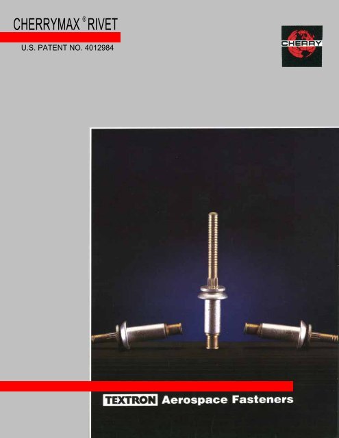
CHERRYMAX ®<br />
RIVET<br />
U.S. PATENT NO. 4012984
WARRANTY<br />
WARRANTY<br />
Textron Aerospace Fasteners, a Division of Textron Inc. (hereinafter “TAF”).<br />
hereby warrants to the initial retail customer (“Warrantee”) only that its<br />
products wiII be free from defects in material and workmanship, provided<br />
that the products are used in accordance with TAFís instruction as to<br />
maintenance, operation and use. The foregoing warranty is limited to<br />
products that are in the original container and the duration of the warranty<br />
is limited to 90 days from the date of first use by the Warrantee.<br />
This Warrantee’s only remedy and TAF’s only obligation in the event of a<br />
defect or failure in the products, iS that TAF will, at its sole option, repair,<br />
replace, or rework the products, but in no case shall the cost of the foregoing<br />
exceed the invoice price of the products.<br />
This Warranty shall be void if any person seeking to make a claim for<br />
defective or failed products fails to notify TAF within thirty (30) days after<br />
receipt of evidence that the product is defective or has failed, or if said<br />
person fails to provide TAF with such evidence as is reasonably requested<br />
concerning the defect or failure, including without limitation, evidence of the<br />
date of purchase and date of installation.<br />
THIS WARRANTY IS IN LIEU OF ALL OTHER WARRANTIES,<br />
EXPRESSED OR IMPLIED, INCLUDING MERCHANTABILITY OR<br />
FITNESS FOR A PARTICULAR PURPOSE. TAF EXPRESSLY DISCLAIMS<br />
LIABILITY FOR ALL INCIDENTAL, CONSEQUENTIAL, OR SPECIAL<br />
DAMAGES ARISING FROM ANY DEFECT OR FAILURE IN ITS<br />
PRODUCTS. TAF FURTHER DISCLAIMS ALL LIABILITY RESULTING<br />
FROM THE USER’S CHOICE OF ITS PRODUCTS FOR ANY PARTICULAR<br />
APPLICATION.<br />
The properties, strengths, dimensions, installed characteristics and all other<br />
information in this catalog is for guidance only to aid in the correct selection<br />
of the products described herein and is not intended or implied as part of<br />
the above warranty. All applications should be evaluated by the user of the<br />
products for functional suitability and evaluations.<br />
NOTE: The properties, strengths, dimensions, installed<br />
characteristics and all other information in this catalog<br />
is for guidance only to aid in the correct selection of<br />
the products described herein and is not intended or<br />
implied as part of the above warranty. All applications<br />
should be evaluated for functional suitability and<br />
available samples of the described parts can be<br />
requested for installed tests, suitability and<br />
evaluations.<br />
Supplier’s Federal Identification Code-11815<br />
ATTENTION<br />
Blind rivets are not always a suitable substitute for<br />
solid rivets. Maintenance personnel are reminded<br />
that AC 43.13-1A chapter 2, section 3 stipulates:<br />
“Do not substitute hollow rivets for solid rivets in<br />
load carrying members without specific approval<br />
of the application by a representative of the Federal<br />
Aviation Administration. Blind rivets may be used in<br />
blind locations in accordance with the conditions<br />
listed in Chapter 5, provided the edgedistances and<br />
spacings are not less than the minimum listed in<br />
paragraph 99d.”
CHERRYMAX ®<br />
RIVET FEATURES AND BENEFITS<br />
CHERRYMAX<br />
.............. .3-4<br />
®<br />
RIVET SELECTION<br />
NUMBERING SYSTEM / HEAD STYLES. ....................... ..5<br />
DIAMETER / GRIP SYSTEM ................................. ..6<br />
MECHANICAL PROPERTIES / GAGES ...........................7<br />
WEIGHT PER 1000 PCS. BY RIVET SIZE ...................... ..8<br />
CHERRYMAX ®<br />
RIVET STANDARDS PAGES<br />
NOMINAL SHANK<br />
UNIVERSAL HEAD ....................................... .9<br />
100° FLUSH HEAD ....................................... 10<br />
100° FLUSH SHEAR HEAD (NAS 1097)<br />
OVERSIZE SHANK DIAMETER<br />
....................... 11<br />
UNIVERSAL HEAD ...................................... .12<br />
100° FLUSH HEAD ...................................... .13<br />
UNISINK HEAD ......................................... .14<br />
120° FLUSH HEAD ...................................... .15<br />
CHERRYMAX ®<br />
RIVET INSTALLATION & INSPECTION<br />
CHERRYMAX<br />
......... .16-18<br />
®<br />
RIVET lNSTALLATION TOOLING<br />
TOOL SELECTION .................................... .19-20<br />
HAND RIVETERS AND KITS ............................... .21<br />
POWER RIVETERS ......................................... 22<br />
POWER RIVETER KITS ................................... .23-24<br />
SPLIT POWER RIVETERS. ................................ ..25<br />
PULLING HEADS .........................................26<br />
EXTENSIONS .................................................27<br />
ADAPTERS & ACCESSORIES ........................... .27-28<br />
MAINTENANCE ITEMS ................................ .29-30<br />
INDEX
CHERRYMAX ®<br />
RIVET FEATURES<br />
3<br />
The CherryMAX ®<br />
<strong>Rivet</strong> is the most reliable, high<br />
strength structural fastener with visual inspectibility in<br />
the world today. It features the “Safe-lock” Locking<br />
Collar for more reliable joint integrity. Meets requirements<br />
of PS-CMR-3000.<br />
CherryMAX ®<br />
<strong>Rivet</strong> consists of four components<br />
assembled as a single unit:<br />
1. A fully serrated stem with break notch, shear-ring and<br />
integral grip adjustment cone.<br />
2. A driving anvil to insure a visible mechanical lock with<br />
each fastener installation.<br />
3. A separate, visible and inspectable locking collar that<br />
mechanically locks the stem to the rivet sleeve.<br />
4. A rivet sleeve with recess in the head to receive the<br />
locking collar.<br />
Covered by U.S. Patent No. 4012984<br />
INSTALLATION<br />
j The CherryMAX ®<br />
<strong>Rivet</strong> is k The pulling head holds the<br />
inserted into the prepared hole. rivet sleeve in place as it begins to<br />
The pulling head (installation tool) pull the rivet stem thru the rivet<br />
is slipped over the rivet’s stem. sleeve. This pulling action causes<br />
Applying a firm, steady pressure, the stem shear ring to upset the<br />
which seats the rivet head, the rivet sleeve and form the "bulbed”<br />
installation tool is then actuated. blind head.<br />
l The continued pulling action of<br />
the installation tool causes the stem<br />
shear ring to shear from the main<br />
body of the stem as the stem con-<br />
tinues to move thru the rivet sleeve.<br />
This action allows the fastener to<br />
accommodate a minimum of 1/16"<br />
variation in structure thickness. The<br />
Locking Collar then contacts the<br />
Driving Anvil. As the stem continues<br />
to be pulled by the action of the<br />
installation tool, the "Safe-lock"<br />
Locking Collar deforms into the<br />
rivet sleeve head recess. Formation<br />
of the rivet sleeve's "bulbed” blind<br />
head is complete.<br />
m The "Safe-lock" Locking Collar<br />
fills the rivet sleeve head recess,<br />
locking the stem and rivet sleeve<br />
securely together. Continued pulling<br />
by the installation tool causes the<br />
stem to fracture at the break notch,<br />
providing a flush, burr-free,<br />
inspectable installation.
DRIVING ANVIL<br />
A driving anvil is part of each CherryMAX ®<br />
<strong>Rivet</strong><br />
assembly. This Driving Anvil eliminates wear and<br />
replacement of expendable installation tool components,<br />
considerably extending the life of the installation tool.<br />
It also allows one pulling head to install:<br />
— 1/8", 5/32", and 3/16" Nominal and Oversize Diameter<br />
<strong>Rivet</strong>s<br />
— Protruding, 100° Flush and 100° Flush Shear,<br />
Unisink, and 120° Flush Head Styles<br />
— All CherryMAX ®<br />
<strong>Rivet</strong> grip lengths<br />
— All CherryMAX ®<br />
<strong>Rivet</strong> sleeve/stem material<br />
combinations<br />
LOCKING COLLAR<br />
The CherryMAX ®<br />
<strong>Rivet</strong> features the patented "Safe-<br />
Lock” Locking Collar which enhances joint integrity and<br />
reliability.<br />
The “Safe-lock” Locking Collar is preformed to the<br />
stem during a sub-assembly operation, then deforms<br />
into the rivet sleeve head recess during installation,<br />
locking the rivet sleeve and stem together.<br />
The “Safe-lock” Locking Collar is visible and inspectable<br />
after installation.<br />
The “Safe-lock” Locking Collar installs flush with the<br />
rivet sleeve head.<br />
The “Safe-lock” Locking Collar is approved for use in<br />
engine inlets and components. They will not vibrate<br />
loose after installation.<br />
RIVET<br />
The CherryMAX ®<br />
<strong>Rivet</strong> is available in both nominal and<br />
1/64" oversize shank diameters and is available in four<br />
material combinations:<br />
— 5056 Aluminum Sleeve/Alloy Steel Stem (50KSI Shear)<br />
— 5056 Aluminum Sleeve/Cres Stem (50KSI Shear)<br />
— Monel Sleeve/Cres Stem (75KSI Shear)<br />
— INCO 600 Sleeve/lNCO X-750 Stem (75KSI Shear)<br />
TOOLING SIMPLICITY<br />
Lightweight, non-shifting installation tools require no<br />
adjusting.<br />
Limited access capability with Right Angle and Offset<br />
Pulling Heads and Extensions for greater reach and<br />
“Split” tools for special applications including automation<br />
and robotics.<br />
BULBED BLIND HEAD<br />
Provides a large bearing surface area on the blind side<br />
of the structure, giving dependable results, even when<br />
installed in difficult thin sheet stack-up applications.<br />
CHERRYMAX ®<br />
RIVET BENEFITS<br />
4
CHERRYMAX ®<br />
5<br />
RIVET SELECTION<br />
NUMBERING SYSTEM<br />
CHERRY PART NUMBER EXAMPLE: CR3242-6-04<br />
HEAD STYLES<br />
UNIVERSAL 100° FLUSH<br />
(MS20470) (MS20426)<br />
For protruding head For countersunk<br />
applications applications<br />
Available in both nominal & oversize Available in both nominal & oversize<br />
UNISINK<br />
A combination flush and protruding<br />
head for use in very thin top sheets.<br />
Eliminates need for<br />
double-dimpling.<br />
Available in oversize only<br />
Maximum Grip Length<br />
in 16ths of an Inch<br />
(-04 = 4/16 = 1/4)<br />
<strong>Rivet</strong> Diameter in<br />
32nds of an Inch<br />
(-6 = 6/32 = 3/16)<br />
Head Style:<br />
Odd Number =<br />
Protruding Head<br />
Even Number =<br />
Flush Head<br />
<strong>Rivet</strong> Type & Material<br />
Combination<br />
(See Pages 9 thru 15)<br />
Cherrymax <strong>Rivet</strong><br />
120° FLUSH<br />
A large diameter, shallow flush head<br />
providing a wide bearing area in thin<br />
top sheet applications.<br />
Available in oversize only<br />
100° FLUSH<br />
(NAS1097)<br />
For thin top sheet, machine<br />
countersunk applications<br />
Available in nominal only
DIAMETER<br />
Bulbed CherryMAX ®<br />
rivets are offered in 1/8" (-4), 5/32" (-5),<br />
3/16" (-6) and 1/4" (-8) shank diameters. They are available in<br />
nominal and 1/64" oversize. A gold colored driving anvil<br />
identifies nominal diameter. A silver colored driving anvil<br />
identifies oversize diameter.<br />
GRIP<br />
The grip range of all CherryMAX ®<br />
rivets is in increments of<br />
1/16", with the last dash number indicating the maximum grip<br />
length in 16ths. Example: -04 grip rivet has a grip range of<br />
3/16" (.188) to 1/4" (.250).<br />
To determine the proper grip rivet to use, measure the<br />
material thickness with a Cherry 269C3 selector gage as<br />
shown here.<br />
Always read to the next higher number.<br />
CHERRYMAX ®<br />
RIVET SELECTION<br />
6
CHERRYMAX ® RIVET SELECTION<br />
7<br />
Materials<br />
Sleeve Stem<br />
5056 Aluminum Alloy Steel<br />
5056 Aluminum CRES<br />
Monel CRES<br />
lnco 600 lnco X-750<br />
MECHANICAL PROPERTIES<br />
Ultimate<br />
Shear Strength<br />
50,000 PSI<br />
50,000 PSI<br />
75,000 PSI<br />
75,000 PSI<br />
MINIMUM RIVET SHEAR & TENSILE STRENGTH (LBS.) IN STEEL COUPONS<br />
Maximum<br />
Temperature<br />
250°F<br />
250°F<br />
900°F<br />
1400°F<br />
SINGLE SHEAR TENSILE<br />
ALUMINUM MONEL INCO ALUMINUM MONEL INCO<br />
Nom. O/S Nom. O/S O/S Nom. O/S Nom. O/S O/S<br />
3212 3242 3522 3552 3852 3212 3214 3242 3522 3524 3552 3852<br />
RIVET SHEET 3213 3243 3523 3553 3853 3213 3224 3243 3523 3553 3853<br />
DIAM. THICK. 3214 3245 3524 3555 3222 3245 3555<br />
3222 3246 3556 3223 3246 3556<br />
3223 3252 3252<br />
3224 3253 3253<br />
3255 3255<br />
1/8 (-4) 2x.156 664 814 995 1220 1220 285 250 345 400 360 490 570<br />
5/32 (-5) 2x.187 1030 1245 1545 1865 1865 445 390 530 635 555 740 860<br />
3/16 (-6) 2x.219 1480 1685 2215 2525 2525 635 560 710 890 800 1000 1160<br />
1/4 (-8) 2x.281 2615 2925 3920 4390 4390 1125 1000 1260 1570 1410 1755 2030<br />
Values shown are fastener capabilities only. Design values will be limited by the bearing strength of the sheet material used.<br />
269C3 GRIP GAGE<br />
NATIONAL STOCK NUMBER 5210-00-255-7544<br />
A simple, self-explanatory gage for determining material<br />
thickness and proper rivet grip length.<br />
T-172 RIVET HOLE SIZE GAGE<br />
These are precision ground, go no-go gages used to<br />
check holes drilled for CherryMAX ® rivets. They are<br />
made in both nominal and oversize rivet diameters.<br />
GAGES<br />
RIVET NATIONAL STOCK RIVET NATIONAL STOCK<br />
DIAMETER GAGE NUMBER NO. DIAMETER GAGE NUMBER NO.<br />
1/8" Nominal T-172-4 5220-00-478-4135 1/8" Oversize T-172-400 5220-00-478-4137<br />
5/32" Nominal T-172-5 5220-01-021-3276 5/32" Oversize T-172-500 5220-00-478-4140<br />
3/16" Nominal T-172-6 5220-00-478-4136 3/16" Oversize T-172-600 5220-00-478-4141<br />
1/4" Nominal T-172-8 5220-00-478-4139 1/4" Oversize T-172-800 5220-01-374-1340<br />
ATTENTION<br />
Blind rivets are not always a suitable substitute for solid rivets. Maintenance personnel are reminded that AC 43.13-1A<br />
chapter 2, section 3 stipulates: “Do not substitute hollow rivets for solid rivets in load carrying members without specific<br />
approval of the application by a representative of the Federal Aviation Administration. Blind rivets may be used in blind<br />
locations in accordance with the conditions listed in Chapter 5, provided the edge distances and spacings are not less<br />
than the minimum listed in paragraph 99d.”
INSTALLED WEIGHTS — Pounds per 1000 pieces (Ref.)<br />
RIVET DIAMETER<br />
AND GRIP LENGTH<br />
-4 (1/8")<br />
3212<br />
3214<br />
3222<br />
3224<br />
CHERRYMAX ®<br />
RIVET SELECTION<br />
ALUMINUM MONEL INCO 600<br />
Nominal Oversize Nominal Oversize Oversize<br />
3213<br />
3223<br />
3242<br />
3246<br />
3252<br />
-01 — .69 — .88 — 1.28 —<br />
-02 .59 .79 .85 .99 1.05 1.52 1.14<br />
-03 .71 .93 .97 1.16 1.24 1.74 1.42<br />
-04 .86 1.07 1.14 1.33 1.44 1.90 1.70<br />
-05 1.00 1.21 1.31 1.50 1.66 2.16 1.98<br />
- 0 6 1.14 1.36 1.47 1.66 1.88 2.38 2.26<br />
-07 1.28 1.50 1.64 1.83 2.00 2.61 2.54<br />
-08 1.42 1.64 1.81 2.00 2.22 2.83 2.82<br />
- 0 9 1.56 1.78 1.98 2.17 2.44 3.05 3.10<br />
-01 — 1.26 — 1.55 —<br />
- 0 2 1.02 1.41 1.34 1.71 1.84<br />
- 0 3 1.22 1.63 1.56 1.98 2.15<br />
-04 1.45 1.86 1.82 2.24 2.50<br />
-5 (5/32") - 0 5 1.67 2.08 2.09 2.51 2.86<br />
-06 1.90 2.31 2.36 2.78 3.22<br />
-07 2.12 2.53 2.63 3.05 3.58<br />
- 0 8 2.35 2.75 2.90 3.32 3.94<br />
-09 2.57 2.98 3.16 3.58 4.29<br />
-10 2.79 3.20 3.43 3.85 4.64<br />
-11 3.01 3.42 3.70 4.12 4.99<br />
-01 — 2.01 —<br />
-02 1.75 2.20 2.00<br />
-03 2.00 2.52 2.28<br />
-04 2.33 2.85 2.62<br />
-05 2.64 3.16 2.97<br />
-6 (3/16") -06 2.97 3.49 3.32<br />
-07 3.28 3.80 3.67<br />
-08 3.61 4.13 4.02<br />
-09 3.93 4.45 4.36<br />
-10 4.25 4.77 4.71<br />
-11 4.57 5.09 5.06<br />
-12 4.90 5.42 5.41<br />
-02 — 4.79 —<br />
-03 4.08 5.35 4.50<br />
-04 4.61 5.92 5.32<br />
-05 5.14 6.49 5.71<br />
-8 (1/4") -06 5.67 7.06 6.28<br />
-07 6.20 7.63 6.91<br />
- 0 8 6.73 8.19 7.54<br />
-09 7.26 8.76 8.17<br />
-10 7.79 9.33 8.80<br />
-11 8.32 9.90 9.43<br />
-12 8.85 10.47 10.06<br />
-13 9.36 11.03 10.69<br />
-14 9.91 11.60 11.32<br />
3243<br />
3245<br />
3253<br />
3255<br />
3522<br />
3524<br />
2.39 —<br />
2.58 3.04<br />
2.93 3.54<br />
3.27 4.04<br />
3.62 4.54<br />
3.97 5.04<br />
4.32 5.54<br />
4.67 6.04<br />
5.01 6.54<br />
5.36 7.04<br />
5.71 7.54<br />
6.06 8.04<br />
— —<br />
5.74 6.98<br />
6.57 7.63<br />
7.14 8.98<br />
7.81 10.04<br />
8.48 11.05<br />
9.11 12.38<br />
9.74 13.01<br />
10.37 13.64<br />
11.00 15.81<br />
11.63 16.78<br />
12.26 17.73<br />
12.89 18.69<br />
3523 3552 3553<br />
3556 3555<br />
2.41<br />
2.81<br />
3.14<br />
3.46<br />
3.81<br />
4.17<br />
4.53<br />
4.92<br />
5.24<br />
5.56<br />
5.87<br />
3.84<br />
4.38<br />
4.87<br />
5.38<br />
5.86<br />
6.36<br />
6.86<br />
7.36<br />
7.86<br />
8.35<br />
8.85<br />
9.34<br />
9.17<br />
—<br />
1.87<br />
2.26<br />
2.87<br />
3.30<br />
3.74<br />
4.18<br />
4.62<br />
5.06<br />
5.50<br />
5.94<br />
—<br />
3.12<br />
3.69<br />
4.27<br />
4.85<br />
5.43<br />
6.01<br />
6.59<br />
7.17<br />
7.75<br />
8.33<br />
8.91<br />
—<br />
10.01 7.45<br />
10.80 8.58<br />
12.29 9.71<br />
13.28 10.84<br />
14.20 11.97<br />
15.26 13.10<br />
16.25 14.23<br />
17.23 15.36<br />
18.21 16.49<br />
19.18 17.62<br />
20.13 18.75<br />
21.09 19.88<br />
1.32<br />
1.58<br />
1.86<br />
2.14<br />
2.42<br />
2.70<br />
2.98<br />
3.26<br />
3.54<br />
2.46<br />
2.90<br />
3.34<br />
3.78<br />
4.22<br />
4.66<br />
5.10<br />
5.54<br />
5.98<br />
6.42<br />
6.86<br />
3.99<br />
4.51<br />
5.08<br />
5.66<br />
6.24<br />
6.82<br />
7.40<br />
7.98<br />
8.56<br />
9.14<br />
9.72<br />
10.30<br />
9.92<br />
10.95<br />
11.98<br />
13.01<br />
14.04<br />
15.07<br />
16.10<br />
17.13<br />
18.16<br />
19.19<br />
20.22<br />
21.25<br />
22.28<br />
3852 3853<br />
— 1.35<br />
1.16 1.61<br />
1.44 1.88<br />
1.72 2.17<br />
2.01 2.44<br />
2.28 2.73<br />
2.56 3.02<br />
2.89 3.29<br />
3.22 3.56<br />
— 2.53<br />
1.99 2.98<br />
2.37 3.44<br />
2.90 3.91<br />
3.33 4.26<br />
3.85 4.77<br />
4.31 5.21<br />
4.75 5.67<br />
5.19 6.13<br />
5.63 6.55<br />
6.07 6.97<br />
— 4.13<br />
3.24 4.65<br />
3.82 5.22<br />
4.33 5.80<br />
4.97 6.37<br />
5.55 6.95<br />
6.13 7.53<br />
6.72 8.11<br />
7.30 8.69<br />
7.88 9.27<br />
8.47 9.85<br />
9.05 10.44<br />
— 10.28<br />
7.73 11.37<br />
8.90 12.42<br />
10.07 13.41<br />
11.24 14.54<br />
12.38 15.67<br />
13.62 16.70<br />
14.80 17.73<br />
15.96 18.76<br />
17.09 19.79<br />
18.24 20.82<br />
19.36 21.86<br />
20.51 22.89<br />
8
CHERRYMAX ®<br />
RIVET<br />
UNIVERSAL HEAD / NOMINAL DIAMETER<br />
9<br />
.010 RAD. MAX.<br />
FOR ALUMINUM<br />
.020 RAD. MAX<br />
FOR MONEL<br />
DIA D B<br />
DASH +.003 A +.010 BK Z HOLE<br />
NO. -.001 ±.010 -.000 MIN (REF) LIMITS<br />
-4 .126 .250 .054 .355 .87 .129-.132<br />
-5 .157 .312 .067 .370 .94 .160-.164<br />
-6 .189 .375 .080 .415 .94 .192-.196<br />
-8 .253 .500 .107 .485 .97 .256-.261<br />
GRIP LIMITS<br />
1/16 -4(1/8") DIAMETER -5(5/32") DIAMETER<br />
DASH +.000 K DASH +.000 K<br />
MIN MAX NO. L - .030 MAX L - .030 MAX<br />
j .062 4-01 .161<br />
.063 .125 4-02 .224<br />
.126 .187 4-03 .287<br />
.188 .250 4-04 .349<br />
.251 .312 4-05 .412<br />
.313 .375 4-06 .474<br />
.376 .437 4-07 .537<br />
.438 .500 4-08 .599<br />
.501 .562 4-09 .662<br />
.563 .625<br />
.626 .687<br />
.688 .750<br />
.751 .812<br />
.813 .875<br />
.38 5-01 .187 .41<br />
.45 5-02 .230 .47<br />
.51 5-03 .293 .53<br />
.57 5-04 .355 .59<br />
.63 5-05 .418 .65<br />
.70 5-06 .480 .72<br />
.76 5-07 .543 .77<br />
.82 5-08 .605 .84<br />
.88 5-09 .668 .90<br />
5-10 .730 .96<br />
5-11 .793 1.02<br />
OPTIONAL MIN BLIND CLEARANCE<br />
CONFIGURATION FOR SATISFACTORY<br />
FOR CRES STEMS INSTALLATION<br />
-6(3/16") DIAMETER -8(1/4") DIAMETER<br />
DASH<br />
NO.<br />
+.000<br />
L - .030<br />
K<br />
MAX<br />
DASH<br />
NO.<br />
+.000<br />
L - .030<br />
K<br />
MAX<br />
6-01 .219 .47<br />
6-02 .262 .51 8-02 .315 .59<br />
6-03 .325 .57 8-03 .378 .65<br />
6-04 .387 .64 8-04 .440 .72<br />
6-05 .450 .70 8-05 .503 .78<br />
6-06 .512 .76 8-06 .565 .84<br />
6-07 .575 .82 8-07 .628 .90<br />
6-08 .637 .88 8-08 .690 .97<br />
6-09 .700 .95 8-09 .753 1.03<br />
6-10 .762 1.01 8-10 .815 1.09<br />
6-11 .825 1.07 8-11 .878 1.15<br />
6-12 .887 1.13 8-12 .940 1.22<br />
8-13 1.003 1.28<br />
8-14 1.065 1.34<br />
RIVET<br />
NUMBER<br />
NAS<br />
523<br />
CODE SLEEVE<br />
MATERIAL m<br />
STEM LOCK COLLAR SLEEVE<br />
FINISH<br />
STEM<br />
5056<br />
8740<br />
A-286<br />
CHEM FILM CAD PLATE<br />
CR 3213 ARN ALUM. ALLOY ALLOY STEEL CRES<br />
MIL-C-5541 QQ-P-416<br />
QQ-A-430 AMS 6322 AMS 5731<br />
PLAIN COLOR TYPE II CL. 2<br />
CR 3223 −<br />
5056<br />
ALUM. ALLOY<br />
QQ-A-430<br />
15-7 PH<br />
CRES<br />
AMS 5657<br />
A-286<br />
CRES<br />
AMS 5731<br />
CHEM FILM<br />
MIL-C-5541<br />
PLAIN COLOR<br />
CAD PLATE<br />
QQ-P-416<br />
TYPE I CL. 2<br />
CR 3523 ATM<br />
MONEL<br />
QQ-N-281<br />
15-7 PH<br />
CRES<br />
AMS 5657<br />
A-286<br />
CRES<br />
AMS 5731<br />
NONE NONE<br />
CR 3523P − MONEL<br />
QQ-N-281<br />
15-7 PH<br />
CRES<br />
AMS 5657<br />
A-286<br />
CRES<br />
AMS 5731<br />
ALUM. COAT<br />
CHERRY<br />
SPEC. C-123<br />
NONE<br />
5 Gold colored driving anvil. Identifies nominal rivets.<br />
LOCK COLLAR<br />
PASSIVATED<br />
NOTE: j Minimum grip for: -4 dia. = .025 2 <strong>Rivet</strong>s with grips greater than their diameter are not required to meet<br />
Minimum grip for: -5 dia. = .031 expansion requirements of procurement specifications.<br />
Minimum grip for: -6 dia. = .037<br />
3 Do not clean or degrease prior to installation-lubricant must not be removed.<br />
m Chemical composition only.
HEAD MARKINGS VISIBLE AFTER INSTALLATION<br />
CHERRYMAX ® RIVET<br />
100° FLUSH HEAD / NOMINAL DIAMETER<br />
DIA D C<br />
DASH +.003 A 1 B BK Z HOLE<br />
NO. -.001 ±.004 (REF) MIN (REF) ALUM MONEL LIMITS<br />
-4 .126 .225 .041 .355 .87 .002-.010 .005-.015 .129-.132<br />
-5 .157 .286 .054 .370 .94 .002-.012 .005-.015 .160-.164<br />
-6 .189 .353 .069 .415 .94 .002-.012 .005-.015 .192-.196<br />
-8 .253 .476 .095 .485 .97 .002-.016 .005-.015 .256-.261<br />
GRIP LIMITS<br />
1/16 -4(1/8") DIAMETER -5(5/32") DIAMETER -6(3/16") DIAMETER -8(1/4") DIAMETER<br />
MIN MAX<br />
DASH<br />
NO.<br />
+.000<br />
L-.030<br />
K<br />
MAX<br />
DASH<br />
NO.<br />
+.000<br />
L-.030<br />
K<br />
MAX<br />
DASH<br />
NO.<br />
+.000<br />
L-.030<br />
K<br />
MAX<br />
DASH<br />
NO.<br />
+.000<br />
L-.030<br />
K<br />
MAX<br />
2 .125 4-02 .224 .45 5-02 .230 .47 6-02 .262 .51<br />
.126 .187 4-03 .287 .51 5-03 .293 .53 6-03 .325 .57 8-03 .378 .65<br />
.188 .250 4-04 .349 .57 5-04 .355 .59 6-04 .387 .34 8-04 .440 .72<br />
.251 .312 4-05 .412 .63 5-05 .418 .65 6-05 .450 .70 8-05 .503 .78<br />
.313 .375 4-06 .474 .70 5-06 .480 .72 6-06 .512 .76 8-06 .565 .84<br />
.376 .437 4-07 .537 .76 5-07 .543 .77 6-07 .575 .82 8-07 .628 .90<br />
.438 .500 4-08 .599 .82 5-08 .605 .84 6-08 .637 .88 8-08 .690 .97<br />
.501 .562 4-09 .662 .88 5-09 .668 .90 6-09 .700 .95 8-09 .753 1.03<br />
.563 .625 5-10 .730 .96 6-10 .762 1.01 8-10 .815 1.09<br />
.626 .687 5-11 .793 1.02 6-11 .825 1.07 8-11 .878 1.15<br />
.688 .750 6-12 .887 1.13 8-12 .940 1.22<br />
.751 .812 8-13 1.003 1.28<br />
.813 .875 8-14 1.065 1.34<br />
RIVET<br />
NUMBER<br />
NAS<br />
523<br />
CODE SLEEVE<br />
MATERIAL 5<br />
STEM LOCK COLLAR SLEEVE<br />
FINISH<br />
STEM LOCK COLLAR<br />
5056 8740 A-286 CHEM FILM CAD PLATE<br />
CR 3212 ARM ALUM. ALLOY<br />
QQ-A-430<br />
ALLOY STEEL<br />
AMS 6322<br />
CRES<br />
AMS 5731<br />
MIL-C-5541<br />
PLAIN COLOR<br />
QQ-P-416<br />
TYPE II CL. 2<br />
CR 3222 —<br />
5056<br />
ALUM. ALLOY<br />
QQ-A-430<br />
15-7 PH<br />
CRES<br />
AMS 5657<br />
A-286<br />
CRES<br />
AMS 5731<br />
CHEM FILM<br />
MIL-C-5541<br />
PLAIN COLOR<br />
CAD PLATE<br />
QQ-P-416<br />
TYPE I CL. 2 PASSIVATED<br />
CR 3522 ATL<br />
MONEL<br />
QQ-N-281<br />
15-7 PH<br />
CRES<br />
AMS 5657<br />
A-286<br />
CRES<br />
AMS 5731<br />
NONE<br />
NONE<br />
CR 3522P —<br />
MONEL<br />
QQ-N-281<br />
15-7 PH<br />
CRES<br />
AMS 5657<br />
A-286<br />
CRES<br />
AMS 5731<br />
ALUM. COAT<br />
SPEC. C-123<br />
NONE<br />
NOTE: 1 Head diameters are to theoretical 3 <strong>Rivet</strong>s with grips greater than their diameter are not required to meet<br />
projection. expansion requirements of procurement specifications.<br />
2 Minimum grip for: -4 dia. = .063<br />
Minimum grip for: -5 dia. = .065<br />
Minimum grip for: -6 dia. = .080<br />
4 Do not clean or degrease prior to installation—lubricant must not be removed.<br />
5 Chemical composition only<br />
6 Gold colored driving anvil. Identifies nominal rivets.<br />
10
CHERRYMAX ®<br />
RIVET<br />
NAS 1097 100° FLUSH SHEAR HEAD / NOMINAL DIAMETER<br />
11<br />
HEAD MARKINGS VISIBLE AFTER INSTALLATION<br />
OPTIONAL MIN BLIND CLEARANCE<br />
CONFIGURATION FOR SATISFACTORY<br />
FOR CRES STEMS INSTALLATION<br />
3214 3224 3524<br />
SEE NOTE 3 & 3524P<br />
DIA<br />
DASH<br />
NO.<br />
D<br />
+.003<br />
-.001<br />
A j<br />
±.004<br />
B<br />
(REF)<br />
BK<br />
MIN<br />
Z<br />
(REF) ALUM<br />
C<br />
MONEL<br />
HOLE<br />
LIMITS<br />
-4 .126 .192 .028 .355 .87 .002-.010 .005-.015 .129-.132<br />
-5 .157 .243 .037 .370 .94 .002-.012 .005-.015 .160-.164<br />
-6 .189 .299 .046 .415 .94 .002-.012 .005-.015 .192-.196<br />
-8 .253 .392 .060 .485 .97 .002-.016 .005-.015 .256-.261<br />
GRIP LIMITS<br />
1/16 -4(1/8") DIAMETER -5(5/32") DIAMETER -6(3/16") DIAMETER -8(1/4") DIAMETER<br />
DASH +.000 K DASH +.000 K DASH +.000 K DASH +.000 K<br />
MIN MAX NO. L-.030 MAX NO. L-.030 MAX NO. L-.030 MAX NO. L-.030 MAX<br />
k .125 4-02 .224 .45 5-02 .230 .47 6-02 .262 .51<br />
.126 .187 4-03 .287 .51 5-03 .293 .53 6-03 .325 .57 8-03 .378 .65<br />
.188 .250 4-04 .349 .57 5-04 .355 .59 6-04 .387 .64 8-04 .440 .72<br />
.251 .312 4-05 .412 .63 5-05 .418 .65 6-05 .450 .70 8-05 .503 .78<br />
.313 .375 4-06 .474 .70 5-06 .480 .72 6-06 .512 .76 8-06 .565 .84<br />
.376 .437 4-07 .537 .76 5-07 .543 .77 6-07 .575 .82 8-07 .628 .90<br />
.438 .500 4-08 .599 .82 5-08 .605 .84 6-08 .637 .88 8-08 .690 .97<br />
.501 .562 4-09 .662 .88 5-09 .668 .90 6-09 .700 .95 8-09 .753 1.03<br />
.563 .625<br />
5-10 .730 .96 6-10 .762 1.01 8-10 .815 1.09<br />
.626 .687<br />
5-11 .793 1.02 6-11 .825 1.07 8-11 .878 1.15<br />
.688 .750<br />
6-12 .887 1.13 8-12 .940 1.22<br />
.751 .812<br />
8-13 1.003 1.28<br />
.813 .875<br />
8-14 1.065 1.34<br />
RIVET<br />
NUMBER<br />
NAS<br />
523<br />
CODE SLEEVE<br />
MATERIAL o<br />
STEM LOCK COLLAR SLEEVE<br />
FINISH<br />
STEM LOCK COLLAR<br />
CR 3214 ASK<br />
5056<br />
ALUM. ALLOY<br />
QQ-A-430<br />
8740<br />
ALLOY STEEL<br />
AMS 6322<br />
A-286<br />
CRES<br />
AMS 5731<br />
CHEM FILM<br />
MIL-C-5541<br />
PLAIN COLOR<br />
CAD PLATE<br />
QQ-P-416<br />
TYPE II CL. 2<br />
CR 3224<br />
CR 3524<br />
ATU<br />
ASD<br />
5056<br />
ALUM. ALLOY<br />
QQ-A-430<br />
MONEL<br />
QQ-N-281<br />
15-7 PH<br />
CRES<br />
AMS 5657<br />
15-7 PH<br />
CRES<br />
AMS 5657<br />
A-286<br />
CRES<br />
AMS 5731<br />
A-286<br />
CRES<br />
AMS 5731<br />
CHEM FILM<br />
MIL-C-5541<br />
PLAIN COLOR<br />
NONE<br />
CAD PLATE<br />
QQ-P-416<br />
TYPE I CL. 2<br />
NONE<br />
PASSIVATED<br />
CR 3524P —<br />
MONEL<br />
QQ-N-281<br />
15-7 PH<br />
CRES<br />
AMS 5657<br />
A-286<br />
CRES<br />
AMS 5731<br />
ALUM. COAT<br />
CHERRY<br />
SPEC. C-123<br />
NONE<br />
NOTE: j Head diameters are to theoretical l -6 and -8 diameter marking only; square depressed marking with dots<br />
projection. identifies Cherrymax -4 and -5 diameters.<br />
k Minimum grip for: -4 dia. = .063 4 <strong>Rivet</strong>s with grips greater than their diameter are not required to meet expansion<br />
Minimum grip for: -5 dia. = .065 requirements of procurement specifications.<br />
Minimum grip for: -6 dia. = .080<br />
5 Do not clean or degrease prior to installation—lubricant must not be removed.<br />
o Chemical composition only.<br />
7 Gold colored driving anvil. Identifies nominal rivets.
CHERRYMAX ® RIVET<br />
DIA D B<br />
DASH +.003 A +.010 BK Z HOLE<br />
NO. -.001 +.010 -.000 MIN (REF) LIMITS<br />
- 4 .140 .250 .054 .390 .87 .143-.146<br />
- 5 .173 .312 .067 .395 .94 .176-.180<br />
- 6 .201 .375 .080 .410 .94 .205-.209<br />
- 8 .267 .500 .107 .490 .96 .271-.275<br />
GRIP LIMITS<br />
1/16<br />
MIN MAX<br />
1<br />
.063<br />
.126<br />
.188<br />
.251<br />
.313<br />
.376<br />
.438<br />
.501<br />
.563<br />
.626<br />
.688<br />
.751<br />
.813<br />
RIVET<br />
NUMBER<br />
CR3243<br />
.062<br />
.125<br />
.187<br />
.250<br />
.312<br />
.375<br />
.437<br />
.500<br />
.562<br />
.625<br />
.687<br />
.750<br />
.812<br />
.875<br />
-4(1/8") DIAMETER<br />
DASH +.000<br />
NO. L-.030 MAX<br />
4-01 .175 .37<br />
4-02 .238 .46<br />
4-03 .301 .52<br />
4-04 .363 .58<br />
4-05 .426 .65<br />
4-06 .488 .71<br />
4-07 .551 .78<br />
4-08 .613 .84<br />
4-09 .676 .90<br />
NAS<br />
523<br />
CODE<br />
ARE<br />
CR3253 ARP<br />
CR 3553<br />
ARG<br />
CR 3553P —<br />
SLEEVE<br />
5056<br />
ALUM. ALLOY<br />
QQ-A-430<br />
5056<br />
ALUM. ALLOY<br />
QQ-A-430<br />
MONEL<br />
QQ-N-281<br />
MONEL<br />
QQ-N-281<br />
-5(5/32") DIAMETER<br />
DASH +.000 K<br />
NO. L-.030 MAX<br />
5-01 .203 .43<br />
5-02 .246 .47<br />
5-03 .309 .53<br />
5-04 .371 .60<br />
5-05 .434 .66<br />
5-06 .496 .72<br />
5-07 .559 .79<br />
5-08 .621 .85<br />
5-09 .684 .91<br />
5-10 .746 .98<br />
5-11 .809 1.04<br />
MATERIAL 4<br />
CR3853 — INCO 600 INCO X-750<br />
AMS 5687 AMS 5698<br />
STEM LOCK COLLAR<br />
8740<br />
ALLOY STEEL<br />
AMS 6322<br />
15-7 PH<br />
CRES<br />
AMS 5657<br />
15-7 PH<br />
CRES<br />
AMS 5657<br />
15-7 PH<br />
CRES<br />
AMS 5657<br />
A-286<br />
CRES<br />
AMS 5731<br />
A-286<br />
CRES<br />
AMS 5731<br />
A-286<br />
CRES<br />
AMS 5731<br />
A-286<br />
CRES<br />
AMS 5731<br />
A-286<br />
CRES<br />
AMS 5731<br />
UNIVERSAL HEAD / OVERSIZE DIAMETER<br />
-6(3/16") DIAMETER<br />
DASH<br />
NO.<br />
6-01<br />
6-02<br />
6-03<br />
6-04<br />
6-05<br />
6-06<br />
6-07<br />
6-08<br />
6-09<br />
6-10<br />
6-11<br />
6-12<br />
+.000<br />
L-.030<br />
.242<br />
.265<br />
.328<br />
.390<br />
.453<br />
.515<br />
.578<br />
.640<br />
.703<br />
.765<br />
.828<br />
.890<br />
SLEEVE<br />
CHEM FILM<br />
MIL-C-5541<br />
PLAIN COLOR<br />
CHEM FILM<br />
MIL-C-5541<br />
PLAIN COLOR<br />
NONE<br />
ALUM.COAT<br />
CHERRY<br />
SPEC. C-123<br />
OPTIONAL MIN BLIND CLEARANCE<br />
CONFIGURATION FOR SATISFACTORY<br />
FOR CRES AND INSTALLATION<br />
INCONEL STEMS<br />
MAX<br />
.45<br />
.50<br />
.55<br />
.62<br />
.68<br />
.74<br />
.82<br />
.89<br />
.95<br />
1.01<br />
1.07<br />
1.14<br />
-8(1/4") DIAMETER<br />
DASH +.000 K<br />
NO. L-.030 MAX<br />
FINISH<br />
STEM<br />
CAD PLATE<br />
QQ-P-416<br />
TYPE II CL. 2<br />
CAD PLATE<br />
QQ-P-416<br />
TYPE I CL.2<br />
8-02 .313<br />
8-03 .375<br />
8-04 .437<br />
8-05 .500<br />
8-06 .562<br />
8-07 .625<br />
8-08 .687<br />
8-09 .750<br />
8-10 .812<br />
8-11 .875<br />
8-12 .937<br />
8-13 1.000<br />
8-14 1.062<br />
NONE PASSIVATED<br />
NONE<br />
NONE NONE<br />
.57<br />
.64<br />
.70<br />
.77<br />
.83<br />
.89<br />
.95<br />
1.02<br />
1.08<br />
1.14<br />
1.20<br />
1.27<br />
1.60<br />
LOCK COLLAR<br />
NOTE: 1 Minimum grip for: -4 dia. = .025 2 <strong>Rivet</strong>s with grips greater than their diameter are not required to meet expansion<br />
Minimum grip for: -5 dia. = .031 requirements of procurement specifications.<br />
Minimum grip for: -6 dia. = .037<br />
3 Do not clean or degrease prior to installation–lubricant must not be removed.<br />
4 Chemical composition only.<br />
5 Silver colored driving anvil. Identifies oversize rivets.<br />
12
CHERRYMAX ®<br />
RIVET<br />
100° FLUSH HEAD / OVERSIZE DIAMETER<br />
13<br />
HEAD MARKINGS VISIBLE AFTER INSTALLATION<br />
DIA<br />
DASH<br />
NO.<br />
D<br />
+.003<br />
-.001<br />
A 1<br />
±.004<br />
B<br />
(REF)<br />
BK<br />
MIN<br />
Z<br />
(REF) ALUM<br />
C<br />
MONEL/lNCO<br />
HOLE<br />
LIMITS<br />
-4 .140 .225 .035 .390 .87 .002-.010 .005-.015 .143-.146<br />
-5 .173 .286 .047 .395 .94 .002-.012 .005-.015 .176-.180<br />
-6 .201 .353 .063 .410 .94 .002-.012 .005-.015 .205-.209<br />
-8 .267 .476 .086 .490 .96 .002-.016 .005-.015 .271-.275<br />
GRIP LIMITS<br />
1/16 -4(1/8") DIAMETER -5(5/32") DIAMETER -6(3/16") DIAMETER -8(1/4") DIAMETER<br />
DASH +.000 K DASH +.000 K DASH +.000 K DASH +.OOO K<br />
MIN MAX NO. L-.030 MAX NO. L-.030 MAX NO. L-.030 MAX NO. L-.030 MAX<br />
.045 .062 4-01 .200 .45<br />
.125 4-02 .238 .45 5-02 .266 .47 6-02 .265 .48<br />
.126 .187 4-03 .301 .52 5-03 .309 .53 6-03 .328 .55 8-03 .375 .64<br />
.188 .250 4-04 .363 .58 5-04 .371 .60 6-04 .390 .62 8-04 .437 .70<br />
.251 .312 4-05 .426 .65 5-05 .434 .66 6-05 .453 .68 8-05 .500 .77<br />
.313 .375 4-06 .488 .71 5-06 .496 .72 6-06 .515 .74 8-06 .562 .83<br />
.376 .437 4-07 .551 .78 5-07 .559 .79 6-07 .578 .82 8-07 .625 .89<br />
.438 .500 4-08 .613 .84 5-08 .621 .85 6-08 .640 .89 8-08 .687 .95<br />
.501 .562 4-09 .676 .90 5-09 .684 .91 6-09 .703 .95 8-09 .750 1.02<br />
.563 .625 5-10 .746 .98 6-10 .765 1.O1 8-10 .812 1.08<br />
.626 .687 5-11 .809 1.04 6-11 .828 1.07 8-11 .875 1.14<br />
.688 .750 5-12 .871 1.10 6-12 .890 1.14 8-12 .937 1.20<br />
.751 .812 6-13 .953 1.20 8-13 1.000 1.27<br />
.813 .875 8-14 1.062 1.60<br />
NAS<br />
RIVET 523<br />
NUMBER CODE<br />
CR 3242<br />
CR 3252<br />
CR 3552<br />
CR 3552P<br />
CR 3852<br />
SLEEVE<br />
5056<br />
ARD ALUM. ALLOY<br />
QQ-A-430<br />
5056<br />
ARO ALUM. ALLOY<br />
QQ-A-430<br />
ARF<br />
—<br />
—<br />
MONEL<br />
QQ-N-281<br />
MONEL<br />
QQ-N-281<br />
INCO 600<br />
AMS 5687<br />
MATERlAL 5 FINISH<br />
STEM LOCK COLLAR<br />
8740<br />
ALLOY STEEL<br />
AMS 6322<br />
15-7 PH<br />
CRES<br />
AMS 5657<br />
15-7 PH<br />
CRES<br />
AMS 5657<br />
15-7 PH<br />
CRES<br />
AMS 5657<br />
INCO X-750<br />
AMS 5698<br />
A-286<br />
CRES<br />
AMS 5731<br />
A-286<br />
CRES<br />
AMS 5731<br />
A-286<br />
CRES<br />
AMS 5731<br />
A-286<br />
CRES<br />
AMS 5731<br />
A-286<br />
CRES<br />
AMS 5731<br />
SLEEVE<br />
CHEM FILM<br />
MIL-C-5541<br />
PLAIN COLOR<br />
CHEM FILM<br />
MIL-C-5541<br />
PLAIN COLOR<br />
NONE<br />
ALUM. COAT<br />
CHERRY<br />
SPEC. C-123<br />
NONE<br />
STEM<br />
CAD PLATE<br />
QQ-P-416<br />
TYPE II CL. 2<br />
CAD PLATE<br />
QQ-P-416<br />
TYPE I CL. 2<br />
LOCK COLLAR<br />
NONE PASSIVATED<br />
NOTE: 1 Head diameters are to theoretical 3 <strong>Rivet</strong>s with grips greater than their diameter are not required to meet expansion<br />
projection. requirements of procurement specifications.<br />
2 Minimum grip for: -4 dia. = .063 4 Do not clean or degrease prior to installation-lubricant must not be removed.<br />
Minimum grip for: -5 dia. = .063<br />
Minimum grip for: -6 dia. = .073<br />
Chemical composition only.<br />
6 Silver colored driving anvil. Identifies oversize rivets.<br />
NONE<br />
NONE
DIA D<br />
DASH +.003<br />
NO. -.001<br />
-4 .140<br />
-5 .173<br />
-6 .201<br />
CHERRYMAX ® RIVET<br />
UNISINK HEAD / OVERSIZE DIAMETER<br />
B<br />
A +.010 C T BK Z HOLE<br />
±.010 -.000 (REF). +.005 MIN (REF) LIMITS<br />
.220 .022 .011 .165 .375 .87 .143-.146<br />
.286 .030 .015 .208 .400 .94 .176-.180<br />
.353 .040 .023 .255 .435 .94 .205-.209<br />
OPTIONAL MIN BLIND CLEARANCE<br />
CONFIGURATION FOR SATISFACTORY<br />
FOR CRES STEMS INSTALLATION<br />
GRIP LIMITS<br />
1/16 -4(1/8") DIAMETER -5(5/32") DIAMETER -6(3/16") DIAMETER<br />
MIN MAX<br />
DASH<br />
NO.<br />
+.000<br />
L -.030 MIX<br />
DASH<br />
NO.<br />
+.000<br />
L -.030 MAX<br />
DASH<br />
NO.<br />
+.000<br />
L-.030<br />
K<br />
MAX<br />
.033 .062 4-01 .170 .39<br />
.063 .125 4-02 .213 .43 5-02 .246 .46 6-02 .265 .50<br />
.126 .187 4-03 .276 .50 5-03 .309 .52 6-03 .328 .56<br />
.188 .250 4-04 .338 .56 5-04 .371 .59 6-04 .390 .62<br />
.251 .312 4-05 .401 .62 5-05 .434 .65 6-05 .453 .68<br />
.313 .375 4-06 .463 .68 5-06 .496 .71 6-06 .515 .75<br />
.376 .437 4-07 .526 .74 5-07 .559 .77 6-07 .578 .81<br />
.438 .500 4-08 .588 .80 5-08 .621 .83 6-08 .540 .87<br />
RIVET<br />
NUMBER<br />
NAS<br />
523<br />
CODE SLEEVE<br />
MATERIAL l<br />
STEM LOCK COLLAR SLEEVE<br />
FINISH<br />
STEM LOCK COLLAR<br />
CR 3245 ATK<br />
5056<br />
ALUM. ALLOY<br />
QQ-A-430<br />
8740<br />
ALLOY STEEL<br />
AMS 6322<br />
A-286<br />
CRES<br />
AMS 5731<br />
CHEM FILM<br />
MIL-C-5541<br />
PLAIN COLOR<br />
CAD PLATE<br />
QQ-P-416<br />
TYPE II CL. 2<br />
CR 3255 —<br />
5056<br />
ALUM. ALLOY<br />
QQ-A-430<br />
15-7 PH<br />
CRES<br />
AMS 5657<br />
A-286<br />
CRES<br />
AMS 5731<br />
CHEM FILM<br />
MIL-C-5541<br />
PLAIN COLOR<br />
CAD PLATE<br />
QQ-P-416<br />
TYPE I CL. 2 PASSIVATED<br />
CR 3555 —<br />
MONEL<br />
QQ-N-281<br />
15-7 PH<br />
CRES<br />
AMS 5657<br />
A-286<br />
CRES<br />
AMS 5731<br />
NONE NONE<br />
CR 3555P —<br />
MONEL<br />
QQ-N-281<br />
15-7 PH<br />
CRES<br />
AMS 5657<br />
A-286<br />
CRES<br />
AMS 5731<br />
ALUM. COAT<br />
CHERRY<br />
SPEC. C-123<br />
NONE<br />
1 <strong>Rivet</strong>s with grips greater than their diameter are not required to meet<br />
expansion requirements of procurement specifications.<br />
2 Do not clean or degrease prior to installation—lubricant must not be removed.<br />
l Chemical composition only.<br />
4 Silver colored driving anvil. Identifies oversize rivets.<br />
14
CHERRYMAX ®<br />
RIVET<br />
120° FLUSH HEAD / OVERSIZE DlAMETER<br />
15<br />
OPTIONAL<br />
CONFIGURATION<br />
FOR CRES STEMS<br />
SLEEVE MATERIAL<br />
M-MONEL<br />
NO I.D. FOR ALUMINUM .010 R.MAX - ALUM<br />
Z<br />
GRIP-<br />
.020 R.MAX - MONEL<br />
HEAD MARKINGS VISIBLE AFTER INSTALLATION<br />
DIA<br />
DASH<br />
NO<br />
-4<br />
-5<br />
-6<br />
DIA<br />
+.003 A j B<br />
-.001 ±.004 (REF)<br />
.140 .272 .038<br />
.173 .314 .041<br />
.201 .350 .048<br />
MIN BLIND CLEARANCE<br />
FOR SATISFACTORY<br />
INSTALLATION<br />
BK<br />
MIN<br />
Z<br />
(REF) ALUM<br />
C<br />
MONEL<br />
HOLE<br />
LIMITS<br />
.390 .87 .002-.010 .005-.015 .143-.146<br />
.395 .94 .002-.012 .005-.015 .176-.180<br />
.410 .94 .002-.012 .005-.015 .205-.209<br />
GRIP LIMITS<br />
1/16 -4(1/8") DIAMETER<br />
-5(5/32") DIAMETER<br />
-6(3/16") DIAMETER<br />
MIN MAX<br />
DASH<br />
NO.<br />
+.000<br />
L -.030<br />
K<br />
MAX<br />
DASH<br />
NO. L<br />
+.000<br />
-.030<br />
K<br />
MAX<br />
DASH<br />
NO<br />
+.000<br />
L -.030<br />
K<br />
MAX<br />
.063 .125 4-02 .238 .45 5-02 .266 .47 6-02 .265 .48<br />
.126 .187 4-03 .301 .52 5-03 .309 .53 6-03 .328 .55<br />
.188 .250 4-04 .363 .58 5-04 .371 .60 6-04 .390 .62<br />
.251 .312 4-05 .426 .65 5-05 .434 .66 6-05 .453 .68<br />
.313 .375 4-06 .488 .71 5-06 .496 .72 6-06 .515 .74<br />
RIVET<br />
NUMBER<br />
NAS<br />
523<br />
CODE SLEEVE<br />
MATERlAL m<br />
STEM LOCK COLLAR SLEEVE<br />
FINISH<br />
STEM LOCK COLLAR<br />
CR 3246 -<br />
5056<br />
ALUM. ALLOY<br />
QQ-A-430<br />
8740<br />
ALLOY STEEL<br />
AMS 6322<br />
A-286<br />
CRES<br />
AMS 5731<br />
CHEM FILM<br />
MIL-C-5541<br />
PLAIN COLOR<br />
CAD PLATE<br />
QQ-P-416<br />
TYPE II CL. 2<br />
CR 3556 -<br />
MONEL<br />
QQ-N-281<br />
15-7 PH<br />
CRES<br />
AMS 5657<br />
A-286<br />
CRES<br />
AMS 5731<br />
NONE NONE PASSIVATED<br />
CR 3556P - MONEL<br />
QQ-N-281<br />
15-7 PH<br />
CRES<br />
AMS 5657<br />
A-286<br />
CRES<br />
AMS 5731<br />
ALUM. COAT<br />
CHERRY<br />
SPEC. C-123<br />
NONE<br />
NOTE: j Head diameters are to theoretical projection.<br />
2 <strong>Rivet</strong>s with grips greater than their diameter are not required to meet expansion<br />
requirements of procurement specifications.<br />
3 Do not clean or degrease prior to installation—lubricant must not be removed.<br />
m Chemical composition only<br />
5 Silver colored driving anvil. identifies oversize rivets.
Use a clean, sharp, properly ground drill. Improperly<br />
ground drills will create oval or oversize holes. Center the<br />
drill in the chuck so that the drill will run true. A “wobble” in<br />
the drill will create an oversize hole. Hold the drill perpendicular<br />
to the surface being drilled. Do not force the drill<br />
through the material.<br />
DO NOT CHAMFER OR OTHERWISE<br />
REMOVE THE SHARP EDGE OF THE<br />
BLIND SIDE OF THE JOINT!<br />
To insure proper hole alignment and to prevent burrs and<br />
chips from lodging between the sheets, the materials to be<br />
riveted should be clamped tightly together. Hole-filling, hollow,<br />
pull-thru rivets may be used in conjunction with springloaded<br />
clamps to prevent material “creep” and hole misalignment<br />
during the drilling operation.<br />
DRILL SIZES<br />
CHERRYMAX ® RIVET INSTALLATION<br />
DRILLING<br />
Drill sizes shown in table below are those which normally produce holes within the specified limits. To assure drilling<br />
accuracy, holes should be checked with a GO/NO-GO gage as shown on page 7.<br />
—NOMlNAL CHERRYMAX— —OVERSIZE CHERRYMAX—<br />
RIVET<br />
DIAMETER<br />
DRILL<br />
SIZE<br />
HOLE SIZE<br />
MIN. MAX.<br />
RIVET<br />
DIAMETER<br />
DRILL<br />
SIZE<br />
HOLE SIZE<br />
MIN. MAX.<br />
-4 (1/8") #30 .129 .132 -4 (1/8") #27 .143 .146<br />
-5 (/32") #20 .160 .164 -5 (5/32") #16 .176 .180<br />
-6 (3/16") #10 .192 .196 -6 (3/16")<br />
#5 .205 .209<br />
-8 (1/4") F .256 .261<br />
-8 (1/4") 1<br />
.271 .275<br />
16
CHERRYMAX ®<br />
RIVET INSTALLATION<br />
17<br />
COUNTERSINKlNG<br />
Accurate countersinking is of primary importance to the<br />
structural integrity of a flush riveted joint. Standard countersinking<br />
procedures as used with solid rivets are also<br />
applicable to CherryMAX rivets. The following points, however,<br />
should be noted:<br />
The countersink pilot should be no more than .001" smaller<br />
than the hole diameter. A greatly undersize pilot will produce<br />
countersinks which are not concentric with the hole,<br />
creating "cocked" head and head gapping problems.<br />
.010 R.MAX<br />
Material thickness for non-dimpled countersinks should<br />
be less than rivet head height (‘B’ dimension) plus .010".<br />
See table for ‘B’ dimensions.<br />
RIVET<br />
DIAMETER<br />
MS20426<br />
100° HEAD<br />
C C<br />
MIN. MAX.<br />
NAS1097<br />
100° HEAD<br />
C C<br />
MIN. MAX.<br />
UNISINK<br />
100° HEAD<br />
C C<br />
MIN. MAX.<br />
120° HEAD<br />
C C<br />
MIN. MAX.<br />
-4 (1/8")<br />
-5 (5/32")<br />
-6 (3/16")<br />
-8 (1/4")<br />
.222<br />
.283<br />
.350<br />
.473<br />
.228<br />
.289<br />
.356<br />
.479<br />
.189<br />
.240<br />
.296<br />
.389<br />
.195<br />
.246<br />
.302<br />
.395<br />
.167<br />
.210<br />
.252<br />
—<br />
.173<br />
.216<br />
.258<br />
—<br />
.269<br />
.311<br />
.347<br />
—<br />
.275<br />
.317<br />
.353<br />
—<br />
COMPARISON CHART OF RIVET HEADS “B” FOR CHERRYMAX FLUSH HEAD RIVETS<br />
RIVET<br />
DIAMETER<br />
B REF.<br />
CR3245<br />
CR3212 CR3214 CR3242<br />
100°<br />
CR3246<br />
100° 100° 100° OVERSIZE 120°<br />
NOMINAL NAS1097 OVERSIZE UNISINK OVERSIZE<br />
- 4 (1/8") .041 .028 .035 .011 .038<br />
- 5 (5/32") .054 .037 .047 .015 .041<br />
- 6 (3/16") .069 .046 .063 .023 .048<br />
- 8 (1/4") .095 .086 .060 — —<br />
The holes in the sheets to be fastened must be of the<br />
correct size and have proper alignment. Do not force<br />
the rivet into the hole! To aid in achieving proper<br />
clamp-up of the sheets, use tack rivets and/or spring<br />
loaded clamps.<br />
PLACING THE RIVET IN THE HOLE<br />
PLACING THE PULLING HEAD ON THE RIVET STEM<br />
Hold the riveter and pulling head in line with the axis of<br />
the rivet as shown in the illustration. Press firmly<br />
against the head of the rivet to minimize head gapping<br />
and sheet gap. Apply a firm, steady pressure and pull<br />
the riveter trigger to begin installation sequence.<br />
The installation cycle will help clamp the sheets<br />
together, seat the rivet head, and break the stem flush<br />
with the head of the rivet.<br />
After the stem breaks, release the trigger.<br />
The pin-tail portion of the stem will be ejected back<br />
thru the riveter head. A stem catcher bag may be<br />
obtained to collect the pin-tails, Part Number 670A20.<br />
See page 28. WARNING: Operating the riveter with a damaged or missing stem<br />
deflector, or using the deflector as a handle, may result in severe<br />
personal injury.
CHERRYMAX ®<br />
RIVET INSPECTION<br />
INSPECTION<br />
Shown is typical installed fastener flushness acceptance<br />
criteria. Locking collar is to be flush with the top<br />
surface of the rivet head. Collar flash permissible is .020<br />
max. Stem flushness shall be as indicated.<br />
TYPICAL<br />
MIN. GRIP<br />
RIVET A MAX. B MAX.<br />
-4 (1/8") .010 .015<br />
-5 (5/32") .010 .020<br />
-6 (6/16") .010 .020<br />
-8 (1/4") .015 .025<br />
IRREGULAR<br />
FORMATION<br />
MIN. GRIP<br />
ACCEPTABLE BLIND HEAD FORMATIONS.<br />
TYPICAL<br />
MAX. GRIP<br />
18
19<br />
CHERRYMAX ®<br />
RIVET TOOLING<br />
CherryMAX ®<br />
tools are reliable, lightweight and versatile...one tool will install six diameters of<br />
rivets in all head styles and all material combinations without a change of pulling heads or<br />
adjustment of the tool.
TOOL SELECTION CHART<br />
CHERRYMAX ®<br />
RIVET TOOLING<br />
The tooling and pulling head combinations shown in the chart below will install the diameter rivets indicated by the shaded areas,<br />
in all grip lengths, head styles, and materials, except as noted.<br />
For more information regarding installation tooling combinations, please contact Technical Service, Textron Aerospace<br />
Fasteners, Santa Ana, CA. 714/850-6048<br />
CHERRY<br />
RIVETER<br />
MODEL<br />
G27<br />
G83<br />
G686B-S<br />
G689<br />
G700<br />
G701 A<br />
G704B<br />
G704B-40SH<br />
G704B-SR<br />
G744<br />
G744-85SH<br />
G749A<br />
G750A<br />
G784<br />
P U L L I N G ALL GRIP LENGTHS, HEAD STYLES & MATERIALS EXCEPT AS NOTED<br />
HEAD<br />
NUMBER -4<br />
—<br />
H701B-456 k<br />
H680B200A<br />
H680B200A<br />
H680B208<br />
H680B200A<br />
H701B-456<br />
H753A-456<br />
H781-456<br />
H701B-456<br />
H753A-456<br />
H781-456<br />
H744A-8<br />
H827-8<br />
H828-8<br />
H846A-456<br />
H749A-456<br />
H753A-456<br />
H781-456<br />
H749-8<br />
—<br />
j Will not install Monel or lnconel fasteners.<br />
k Requires use of 700-244.<br />
NOMINAL DIAMETER.<br />
-5 -6 - 8<br />
j<br />
OVERSIZE DIAMETER<br />
-4 -5 -6 -8<br />
H750A-8<br />
H680B200A<br />
H680B208 j j<br />
20
CHERRYMAX ®<br />
RIVET TOOLING<br />
21<br />
HAND RIVETERS & KITS<br />
To obtain optimum advantage of CherryMAX ®<br />
fasteners, it is recommended that CherryMAX® tooling be selected<br />
to install those fasteners.<br />
G27<br />
NATIONAL STOCK NUMBER 5120-01-393-1538<br />
The G27 is a light-weight (13 oz) hand tool for use in low<br />
production applications such as repair, maintenance or<br />
prototype work. It is packaged in a rugged plastic case<br />
with room for an assortment of popular usage rivets. The<br />
pulling head is an integral part of this riveter.<br />
G750A<br />
NATIONAL STOCK NUMBER 5120-01-432-9361<br />
The Cherry G750A hand hydraulic riveting tool provides the<br />
versatility of a pneumatic-hydraulic riveter but with the<br />
lightweight, high pull strength ratio desirability not found in<br />
other hand riveters. The Cherry G750A has a unique 2-stage<br />
hydraulic power cylinder that provides the user with the ease of<br />
pulling the handle without the strain normally endured to install<br />
a high strength fastener. This patentable 2-stage power feature<br />
allows the user to squeeze the handle throughout the increase<br />
power requirement, without feeling the need to squeeze harder<br />
to install the fastener. The Cherry G750A hand riveter can<br />
install a variety of blind fastener styles, diameters, head<br />
configurations, and material combinations. The G750A with the<br />
standard pulling head can install CherryMAX® and SST<br />
blind rivets in -4, -5, -6, diameters, and -05, -06 diameter<br />
MaxiBOLT blind bolts or threaded inserts by simply changing<br />
the pulling head.<br />
G750ACMR<br />
NATIONAL STOCK NUMBER 5120-01-432-6190<br />
The Cherry G750ACMR hydraulic riveter tool kit includes the<br />
G750A with an H750A-456 pulling head, and adapter<br />
assembly, a right angle pulling head, an offset pulling head and<br />
a sturdy plastic carrying case.<br />
1 Ea. G750A Hydraulic Hand <strong>Rivet</strong>er<br />
(Includes Pulling Head)<br />
1 Ea. H781-456 Offset Pulling Head<br />
1 Ea. H753A-456 Right Angle Pulling Head<br />
1 Ea. 750A-088 Adapter Assembly<br />
1 Ea. H781-456 Tool Sheet<br />
1 Ea. H753A-456 Tool Sheet
G7O1A<br />
NATIONAL STOCK NUMBER 5130-01-044-7206<br />
MILITARY PART NUMBER M85188T1<br />
The G701A weighs 3½ Ibs. and can be operated in any<br />
position. It has a rivet setting stroke of .492", and a pulling<br />
capacity of 1614 Ibs. on 90 psi air pressure at the inlet.<br />
The G701A consumes approximately 2 CFM of air at 20<br />
cycles per minute and its maximum noise level under<br />
load does not exceed 85 dB(A).<br />
G704B<br />
NATIONAL STOCK NUMBER 5130-01-393-1584<br />
MILITARY PART NUMBER M85188T2<br />
The G704B weighs 4½ Ibs. and can be operated in any<br />
position. It has a rivet setting stroke of .518" and a pulling<br />
capacity of 3136 Ibs. on 90 psi air pressure at the inlet.<br />
Normal operating air pressure is 90-120 psi at the inlet.<br />
The G704B consumes approximately 4 CFM of air at 20<br />
cycles per minute and its maximum noise level under<br />
load does not exceed 85 dB(A).<br />
G744<br />
NATIONAL STOCK NUMBER 5130-01-151-1856<br />
The G744 weighs 7 Ibs. and can be operated in any<br />
position. It has a rivet setting stroke of .625" and a pulling<br />
capacity of 3800 Ibs. on 90 psi air pressure at the inlet.<br />
Normal operating air pressure is 90-120 psi at the inlet.<br />
The G744 consumes approximately 6.5 CFM of air at 20<br />
cycles per minute and its maximum noise level under<br />
load is 85 dB(A).<br />
POWER RIVETERS<br />
NOTE: Pulling Heads for the tools described below must be<br />
ordered separately. They are listed in the Tool Selection<br />
Chart on page 20.<br />
CHERRYMAX ®<br />
RIVET TOOLING<br />
* WARNING: Operating these tools with a damaged or missing<br />
stem deflector, or using deflector as a handle, may result in<br />
severe personal injury. 22
CHERRYMAX ®<br />
RIVET TOOLING<br />
23<br />
G704B/G750A-CMR<br />
HAND/POWER RIVETER KITS<br />
The G704B/G750A-CMR Power and Hand <strong>Rivet</strong>er Kit weighs<br />
just 26 Ibs. and contains all the tools necessary to install 1/8".<br />
5/32" and 3/16" diameter CherryMAX rivets in all head styles,<br />
materials and grip lengths. The kit is readily portable and<br />
allows the operator to install rivets with or without compressed<br />
air. The kit includes the Cherry G704B power riveter for riveting<br />
at production speed and the G750A hand tool which permits<br />
riveting where compressed air is unavailable. Details and<br />
dimensions of the riveter and pulling head are outlined<br />
elsewhere in this catalog.<br />
The G704B/G750A-CMR Kit contains the following items:<br />
1 Ea. G704B Power <strong>Rivet</strong>er<br />
1 Ea. G750A Hand <strong>Rivet</strong>er<br />
1 Ea. H701B-456 Straight Pulling Head<br />
1 Ea. H781-456 Offset Pulling Head<br />
1 Ea. H753A-456 Right Angle Pulling Head<br />
1 Ea. 700A77 Air Bleeder<br />
1 Ea. 745A45 Air Bleeder<br />
1 Ea. 750A-088 Adapter Assembly<br />
1 Ea. 704A12-6 6" Extension<br />
1 Ea. 704A12-12 12" Extension<br />
1 Ea. 670A20 Stem Catcher Bag<br />
1 Ea. P1258 Metal Tool Box<br />
1 Ea. 750-040 Air Bleeder Adapter<br />
1 Ea. 700A77 Air Bleeder<br />
1 Ea. 745A45 Air Bleeder<br />
1 Ea. G704B Power <strong>Rivet</strong>er Manual<br />
1 Ea. G750A Hand <strong>Rivet</strong>er Manual<br />
7 Ea. Pulling Head Tool Sheets<br />
1 Ea. 269C3 Selector Gage<br />
1 Ea. CherryMAX Process Manual<br />
1 Ea. CherryMAX Pocket Card
G704BCMR<br />
NATIONAL STOCK NUMBER 5130-01-089-1229<br />
The G704BCMR Power <strong>Rivet</strong>er Kit weighs just 13-1/2 Ibs.<br />
and contains all the tools necessary to install 1/8,5/32<br />
and 3/16" diameter CherryMAX rivets in all head styles,<br />
materials and grip lengths. The kit is readily portable and<br />
where compressed air is available, will permit riveting at<br />
production speed. Details and dimensions of the riveter<br />
and pulling head are outlined elsewhere in this catalog.<br />
The G704BCMR Power <strong>Rivet</strong>er Kit contains the following<br />
items:<br />
1 Ea. G704B Power <strong>Rivet</strong>er<br />
1 Ea. H701B-456 Straight Pulling Head<br />
1 Ea. 700A77 Air Bleeder<br />
1 Ea. 269C3 Selector Gage<br />
1 Ea. 670A20 Stem Catcher Bag<br />
1 Ea. P1258 Metal Carrying Case<br />
1 Ea. G704B Power <strong>Rivet</strong>er Manual<br />
1 Ea. H701B-456 Pulling Head Sheet<br />
1 Ea. CherryMAX Process Manual<br />
1 Ea. CherryMAX Pocket Card<br />
G744CMR<br />
NATIONAL STOCK NUMBER 5130-01-154-7052<br />
The G744CMR Power <strong>Rivet</strong>er Kit weighs just 18 Ibs. and<br />
contains all the tools necessary to install 1/8,5/32,3/16<br />
and 1/4" diameter CherryMAX rivets in all head styles,<br />
materials and grip lengths. The kit is readily portable and<br />
where compressed air is available, will permit riveting at<br />
production speed. Details and dimensions of the riveter<br />
and pulling head are outlined elsewhere in this catalog.<br />
The G744CMR Power <strong>Rivet</strong>er Kit contains the following<br />
items:<br />
1 Ea.G744 Power <strong>Rivet</strong>er<br />
1 Ea. H744A-8 Straight Pulling Head<br />
1 Ea. H846A-456 Straight Pulling Head<br />
1 Ea. 700A77 Air Bleeder<br />
1 Ea. 269C3 Selector Gage<br />
1 Ea. 670A20 Stem Catcher Bag<br />
1 Set T172 Hole Gages (8 sizes)<br />
2 Ea. 1/8" Allen Keys<br />
1 Ea. G744 Power <strong>Rivet</strong>er Manual<br />
1 Ea. H744A-8 Pulling Head Sheet<br />
1 Ea. H846A-456 Pulling Head Sheet<br />
1 Ea. CherryMAX Process Manual<br />
1 Ea. CherryMAX Pocket Card<br />
1 Ea. P1258 Metal Carrying Case<br />
POWER RIVETER KITS<br />
CHERRYMAX ®<br />
RIVET TOOLING<br />
24
CHERRYMAX® RIVET TOOLING<br />
25<br />
G704B-SR AND G704B-40SR<br />
G704B-SR NATIONAL STOCK NUMBER 5130-01-237-0488<br />
The G704B-SR and G704B-40SR Split <strong>Rivet</strong>ers were designed<br />
specifically for the installation of CherryMAX rivets in extremely<br />
limited access applications. They transmit power from the power<br />
unit through three feet of flexible hose (for the G704BSR), and<br />
eight feet of hose (for the G704B-40SR), to a small, lightweight<br />
head. By utilizing the appropriate pulling head, design problems<br />
and operator fatigue can be greatly reduced.<br />
The riveters have a rivet setting stroke of .518" and a pulling<br />
capacity of 3136 Ibs. on 90 psi air pressure at the air inlet.<br />
Normal operating air pressure range is 90-120 psi at the inlet.<br />
The maximum noise level under load does not exceed 85dB(A).<br />
Pulling heads must be ordered separately. They are listed, along<br />
with the riveter's capacity (same as the G704B), in the tool<br />
selection chart on page 20.<br />
G704B-40SH AND G744-85SH<br />
G704B-40SH NATIONAL STOCK NUMBER 5130-01-374-1335<br />
The G704B-40SH and G744-85SH Split CherryMAX<br />
<strong>Rivet</strong>ers are designed specifically for the easiest and most<br />
efficient installation of CherryMAX rivets. In using these<br />
“split” tools, the power unit rests on the floor and transmits<br />
its power through 8 feet of hose to a lightweight pistol-grip<br />
handle. This facilitates rivet installation in many limited<br />
access areas and also greatly reduces operator fatigue.<br />
The G704B-40SH and G744-85SH <strong>Rivet</strong>ers operate on<br />
90 - 120 psi of air pressure at the air inlet and differ in<br />
capacity as follows:<br />
G704B-40SH . . . . . . . .518" stroke. . . . . . . .3136 Ibs. pull<br />
G744-85SH . . . . . . . .625" stroke. . . . . . . .3800 Ibs. pull<br />
The difference in stroke and pull determines the<br />
rivets that can be installed with these riveters.<br />
SPLIT POWER RIVETERS<br />
size of<br />
Pulling heads must be ordered separately. They are listed,<br />
along with the riveter’s capacity, in the tool selection chart<br />
on page 20.
PULLING HEADS<br />
CHERRYMAX ®<br />
RIVET TOOLING<br />
The pulling heads shown below are not furnished with riveters and must be ordered separately. When selecting the<br />
proper pulling head refer to the tool selection chart on page 20 for the appropriate riveter/pulling head combination.<br />
FOR INSTALLING 1/8, 5/32 AND 3/16" NOMINAL & OVERSIZE CHERRYMAX ®<br />
RIVETS<br />
H749A-456 STRAIGHT H680B200A STRAIGHT<br />
NSN 5130-01-104-5370 NSN 5130-01-044-7198<br />
H701B-456 STRAIGHT<br />
NSN 5130-01-393-2927<br />
Military Part Number M85188S1<br />
H846A-456 STRAIGHT<br />
*Use 744A20 adapter when used with G744<br />
**H781-456 replaces H763-456<br />
*H753A-456 RIGHT ANGLE<br />
NSN 5130-01-393-2926<br />
Military Part Number M85188S2<br />
**H781-456 OFFSET<br />
NSN 5130-01-393-2925<br />
Military Part Number M85188S3<br />
FOR INSTALLING 1/4" NOMINAL AND OVERSIZE CHERRYMAX ®<br />
RIVETS<br />
H744A-8 STRAIGHT<br />
H749-8 STRAIGHT<br />
NSN 5130-01-332-4858<br />
H680B208 STRAIGHT<br />
*H827-8 OFFSET<br />
*Available by order only<br />
H828-8 RIGHT ANGLE<br />
26
CHERRYMAX ®<br />
RIVET TOOLING<br />
27<br />
EXTENSIONS<br />
Combinations of these extensions may be used to reach many restricted installation areas by increasing the overall<br />
length of the pulling head.<br />
704A12-2 (2") NSN 5130-01-145-0206<br />
704A12-4 (4') NSN 5130-01-1450207<br />
704A12-6 (6") NSN 5130-01-145-0208<br />
704A12-12 (12") NSN 5130-01-178-0331<br />
These extensions will fit directly on to the G701A,<br />
G704B, G749A, G845A and G846 CherryMAX® <strong>Rivet</strong>ers<br />
and will accept any of the pulling heads listed for those<br />
riveters in the Tool Selection Chart on page 20.<br />
744B35-2 (2")<br />
744B35-4 (4")<br />
744B35-6 (6")<br />
744B3512 (12")<br />
Any combination of these extensions may be used to<br />
reach the desired length. They fit directly on the G-744<br />
CherryMAX riveters and will accept any of the pulling<br />
heads listed for that riveter in the tool selection chart<br />
on page 20.<br />
753B21 (1-1/8")<br />
This extension increases the overall length of the<br />
H753A-456 right angle pulling head nosepiece to<br />
approximately 2-3/16", enabling it to reach into more<br />
restricted areas.<br />
ADAPTERS<br />
These adapters fit the G701A, G704B, G749A, G845A, and G846 CherryMAX ®<br />
riveters to accept pulling heads<br />
designed for the installation of MS-type blind rivets in shorter grip lengths.<br />
704A6 NSN 5130-01-145-6189<br />
Permits the use of H9040 snap-on type pulling head.<br />
704A9 NSN 5130-01-134-8231<br />
Permits the use of H9015 screw-on type pulling head.
ADAPTERS<br />
CHERRYMAX ®<br />
RIVET TOOLING<br />
These adapters permit various Cherry riveters to accept pulling heads for the installation of CherryMAX rivets that the<br />
riveters were not originally intended to pull.<br />
6808205 NSN 5130-01-175-4015<br />
Permits the G686B-S, G689, G700 and G784 to accept<br />
the H753A-456 and H781-456 pulling heads for installing<br />
1/8, 5/32 and 3/16" CherryMAX ®<br />
rivets.<br />
744A20<br />
Permits the G744 riveter to accept the H701-456,<br />
H753-456 and H781-456 pulling heads for installing 1/8,<br />
5/32 and 3/16" CherryMAX ®<br />
rivets and G846 up to -4<br />
grip wiredraw rivets.<br />
740A26<br />
Permits the G740A and G86A Cherry riveters to accept<br />
the H749A-456, H753A-456 and H781-456 pulling heads<br />
for installing 1/8, 5/32 and 3/16" CherryMAX ®<br />
rivets.<br />
701B32 MAGNETIC DRIVING ANVIL CATCHER<br />
The 701B32 magnetic driving anvil catcher provides a<br />
method to securely catch and hold the driving anvil as<br />
they fall away after CherryMAX ®<br />
rivet installation. This<br />
anvil catcher slips onto the nose of the pulling head<br />
without any need for permanent attachment.<br />
670A20 STEM CATCHER BAG<br />
NSN 5130-01-154-1141<br />
ACCESSORIES<br />
The 620A20 stem catcher bag is a convenient accessory<br />
which helps eliminate litter from the shop floor. This<br />
plastic bag equipped with a heavy-duty zipper snaps<br />
over the stem deflector of the G701A, G704B, G744,<br />
G845A, and G846 CherryMAX ®<br />
riveters to catch the<br />
spent stems as they are ejected from the rear of the<br />
riveter head.<br />
700D107 URETHANE BASE PLATE<br />
The 700D107 Urethane Base Plate replaces the stand-<br />
- ard aluminum base plate of the G704B, G704B-SR, and<br />
G846 riveters. The urethane base stabilizes the riveter,<br />
lightens it, is shock absorbing, and protects finished<br />
surfaces from marring. The urethane base is impervious<br />
to industrial solvents, installs easily, and adds to overall<br />
installation tool performance.<br />
28
CHERRYMAX ®<br />
RIVET TOOLING<br />
29<br />
MAINTENANCE ITEMS<br />
To keep CherryMAX hydraulic tools operating at peak efficiency, it is absolutely essential that the hydraulic system be<br />
kept full of fluid and free of air.<br />
Based on the same principle used in bleeding the hydraulic brake system of an automobile, the Cherry Air Bleeders<br />
shown below will quickly and easily remove all air and assure the complete filling of the tool with hydraulic fluid. They may<br />
be used in the tool crib or right on the production line, since it requires but a few minutes to perform this vital function. The<br />
air bleeder is a small item, but does a really big job . . . it prevents downtime.<br />
700A77 AIR BLEEDER<br />
NSN 5130-01-104-5372<br />
For servicing all Cherry pneumatic/hydraulic power<br />
riveters.<br />
745845 AIR BLEEDER<br />
NSN 5120-01-089-1230<br />
For servicing the Cherry G749A hydraulic hand riveter.<br />
An assortment of O-rings, seals, screws, washers and<br />
gaskets likely to need replacing in time, is available in kit<br />
form for each Cherry power riveter. To avoid unnecessary<br />
downtime, it is advisable to have these kits on hand for the<br />
tools to be serviced:<br />
CHERRY TOOL SERVICE KIT NO. NSN#<br />
G701A<br />
G701KS<br />
—<br />
G704B<br />
G704KS 5130-01-105-4177<br />
G704B-SR G704KS 5130-01-105-4177<br />
G704B-40SH G704B-40SHKS<br />
—<br />
G704B-40SR G704B-40SHKS<br />
—<br />
G744<br />
G744KS 5130-01-267-9952<br />
G744-85SH G744-85SHKS<br />
—<br />
G749A<br />
G749KS<br />
—<br />
G750A<br />
G750AKS<br />
—
CHERRYMAX ®<br />
RIVET TOOLING<br />
MAINTENANCE ITEMS<br />
DISASSEMBLY/ASSEMBLY TOOLS<br />
To completely dismantle and reassemble Cherry hydraulic tools, it is advisable to use certain special wrenches designed<br />
for that purpose as shown below:<br />
POWER CYLINDER TOOL<br />
RIVETER NO. TOOL NO. NSN#<br />
G70lA 702B62 —<br />
G704B 700A62 5130-01-104-5371<br />
G744 700A62 5130-01-104-5371<br />
700B65 PACKING PLUG WRENCH<br />
NSN 5130-01-104-5373<br />
700B61 PISTON ROD WRENCH<br />
NSN 5130-01-108-5000<br />
700A60 SEAL GUIDE<br />
NSN 5130-01-267-9839<br />
The tools listed below are for use in dismantling and reassembling the air inlet valve on Cherry hydraulic tools:<br />
VALVE SPRING INSTALLATION KIT<br />
RIVETER NO. KIT NO. N S N #<br />
G701 A 836B700 —<br />
G704B 836B700 —<br />
G744 836B740 5130-01-267-9841<br />
VALVE SLEEVE REMOVAL KIT<br />
RIVETER NO. KIT NO. N S N #<br />
G701A 837B700 —<br />
G704B 837B700 —<br />
G744 837B740 5130-01-267-9840<br />
P-1178 VALVE SPOOL EXTRACTOR<br />
30
G750A<br />
CHERRY<br />
G750A Hand-<strong>Rivet</strong>er The Cherry hand hydraulic riveting tool provides the versatility<br />
of a pneumatic-hydraulic riveter, but ,with the lightweight, high strength ratio<br />
desirability not found in other hand riveters.<br />
Aerospace Fasteners<br />
1224 East Warner Ave., P.O. Box 2157, Santa Ana, CA 92707-0157<br />
(714) 545-5511 FAX (714) 850-6095 Avdel<br />
© 1997 TEXTRON AEROSPACE FASTENERS SUPPLIERS FEDERAL I.D. CODE - 11815 CA-42-7.5-0497