HALFEN HIT INSULATED CONNECTION NEW!
HALFEN HIT INSULATED CONNECTION NEW!
HALFEN HIT INSULATED CONNECTION NEW!

You also want an ePaper? Increase the reach of your titles
YUMPU automatically turns print PDFs into web optimized ePapers that Google loves.
<strong>HALFEN</strong> <strong>HIT</strong> <strong>INSULATED</strong> <strong>CONNECTION</strong><br />
CONCRETE<br />
<strong>NEW</strong>!<br />
•<br />
• incl. technical information according to EC2<br />
• Ψ-values approved by DIBt<br />
• Ψ-values calculation App now available<br />
• certifi ed by the Passive House Institute<br />
• introducing the new solution<br />
for cantilevered corner balconies<br />
and the new multi-part-design<br />
<strong>HIT</strong> 13 - E<br />
N a t i o n a l T e c h n i c a l A p p r o v a l<br />
values
2<br />
Innovation is our standard<br />
The new <strong>HIT</strong> by <strong>HALFEN</strong><br />
Type tested solution for corner balconies<br />
using standard elements.<br />
Low heat-loss with 80 mm joint width, also<br />
available for large loads, certified by the<br />
Passive House Institute!<br />
120 min fire protection on all sides,<br />
non-combustible insulation material –<br />
as standard without any extra cost.<br />
EnEV compliant with the Ψ-values of<br />
the National Technical Approval.<br />
Flexible multi-part modular system –<br />
with quick and efficient delivery.<br />
Mobile app available to calculate Ψ-values.<br />
Thermal bridge reduced<br />
Construction<br />
N a t i o n a l T e c h n i c a l A p p r o v a l<br />
values<br />
REI 120<br />
F 120<br />
© 2013 <strong>HALFEN</strong> · <strong>HIT</strong> 13-E · www.halfen.com
<strong>HALFEN</strong> <strong>HIT</strong> <strong>INSULATED</strong> <strong>CONNECTION</strong><br />
Contents<br />
The benefi ts of <strong>HIT</strong>-HP High Performance and <strong>HIT</strong>-SP Superior Performance 4<br />
Product overview 6<br />
Product description 10<br />
Chapter 1<br />
Chapter 2<br />
Chapter 3<br />
Chapter 4<br />
Chapter 5<br />
Chapter 6<br />
Chapter 7<br />
Chapter 8<br />
- <strong>HIT</strong>-HP MV, <strong>HIT</strong>-SP MV 11<br />
- <strong>HIT</strong>-HP MV-COR, <strong>HIT</strong>-SP MV-COR 26<br />
- <strong>HIT</strong>-BX(-BF)±Q, <strong>HIT</strong>-BX(-BF)±Q-MOD 37<br />
- <strong>HIT</strong>-BX and <strong>HIT</strong>-BF with height off set and wall connection 49<br />
- <strong>HIT</strong>-BQ, <strong>HIT</strong>- ±BQ 57<br />
- <strong>HIT</strong>-VT 62<br />
- <strong>HIT</strong>-HT 67<br />
- <strong>HIT</strong>-BD 71<br />
- <strong>HIT</strong>-FT, <strong>HIT</strong>-OT, <strong>HIT</strong>-AT 75<br />
- <strong>HIT</strong>-ST, <strong>HIT</strong>-WT 79<br />
Building physics, Technical Information 83<br />
Chapter 9<br />
- Basics of thermal insulation 84<br />
- Building authority approved thermal values 88<br />
- Passive House Institute certifi cation 90<br />
- Sound protection according to DIN 4109 91<br />
- Fire protection according to DIN EN 13501 and DIN 4102 92<br />
<strong>HIT</strong> Software 94<br />
Tender specifi cation 96<br />
Optimized off cuts 97<br />
Project check list 99<br />
© 2013 <strong>HALFEN</strong> · <strong>HIT</strong> 13-E · www.halfen.com<br />
<strong>HIT</strong>-HP MV<br />
<strong>HIT</strong>-SP MV<br />
<strong>HIT</strong>-HP MV-COR<br />
<strong>HIT</strong>- SP MV-COR<br />
N a t i o n a l T e c h n i c a l A p p r o v a l<br />
values<br />
3
<strong>HALFEN</strong> <strong>HIT</strong> ISO-ELEMENT HIGH AND SUPERIOR PERFORMANCE<br />
General<br />
4<br />
<strong>HALFEN</strong> <strong>HIT</strong> Insulated connections – always a good decision<br />
min<br />
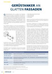
Example of a wall structure with <strong>HALFEN</strong> Insulated connection <strong>HIT</strong>-HP MV<br />
14 %<br />
20 %<br />
32 %<br />
100 %<br />
SP<br />
HP<br />
BX<br />
20°C<br />
10°C<br />
min min <br />
<br />
<strong>HALFEN</strong> has invested research and time to improve the successful fi rst generation <strong>HIT</strong>. The following is a summary of the most<br />
important benefi ts available to you with the <strong>HIT</strong>-HP MV and <strong>HIT</strong>-SP MV. Convince yourself of the benifi ts with your next project.<br />
Thermal Insulation<br />
Eff ective thermal separation of the balcony slab<br />
Compliant with requirements with <strong>HALFEN</strong> <strong>HIT</strong> Iso-Elements:<br />
Thermal transmission coefficient ψ<br />
Details of the thermal conductivity<br />
can be found ff . page 87.<br />
Concrete<br />
without<br />
<strong>HIT</strong> unit<br />
Temperature θ min; Example of a façade with<br />
ETICS (external thermal insulation composite system)<br />
Certifi ed by the Passive House Institute<br />
• for <strong>HIT</strong>-HP: insulating joint from 80 m<br />
• also for max. load capacities with <strong>HIT</strong>-SP<br />
Thermal bridge reduced<br />
Construction<br />
In accordance with EnEV with building authority<br />
approved ψ values<br />
N a t i o n a l T e c h n i c a l A p p r o v a l<br />
values<br />
Improved thermal insulating properties by:<br />
• innovative compression shear bearings CSB made of ultrahigh<br />
strength fi bre-reinforced mortar with increased thermal<br />
insulating properties and an optimized cross-section<br />
• reduced tension bar cross-section in the insulating joint<br />
• substantial reduction of penetration points and conti nuous<br />
insulating material thickness through use of mineral wool<br />
as thermally insulating fi re protection material<br />
x y<br />
© 2013 <strong>HALFEN</strong> · <strong>HIT</strong> 13-E · www.halfen.com
<strong>HALFEN</strong> <strong>HIT</strong> ISO-ELEMENT HIGH AND SUPERIOR PERFORMANCE<br />
General<br />
Further advantages at a glance<br />
Fire protection<br />
• REI 120 (F120) as standard for all <strong>HIT</strong>-HP MV<br />
and <strong>HIT</strong>-SP MV elements<br />
• non-combustible insulation material<br />
of building material class A1<br />
• no installation of lateral fi re boards due to<br />
fi re protection material on all sides<br />
• no confusion of elements with and without<br />
fi re protection requirement<br />
• no additional installation time or work for REI 120 (F120)<br />
Details of the fi re protection properties<br />
can be found ff . page 92<br />
RAL quality symbol<br />
National Technical<br />
DIBt<br />
Approval<br />
© 2013 <strong>HALFEN</strong> · <strong>HIT</strong> 13-E · www.halfen.com<br />
REI 120<br />
F 120<br />
Certifi ed by; RAL German Institut for Quality Assurance and<br />
Certifi cation, RAL Quality Mark Anchoring- and Reinforcement<br />
technology RAL-GZ 658/2<br />
The RAL Quality Mark guarantees compliance with the<br />
technical product requirements<br />
and the related services regarding:<br />
• Specification, quality management, logistics,<br />
competent technical advice, high-quality technical<br />
documentation and software and fulfilment of the<br />
guaranteed benefits.<br />
Biannual monitoring provided by German Lloyd<br />
guarantees that the recommended requirements of the<br />
quality control association for Anchor and reinforcement<br />
technology (Gütegemeinschaft Verankerungsund<br />
Bewehrungstechnik e.V) are maintained.<br />
• DIBt-approved and type-tested<br />
• user friendly software with optimized off cuts<br />
Installation and functionality<br />
<br />
≤ 160 kN/m<br />
≥ 16 cm<br />
<br />
• Robust plastic casing with 3D fi xing of all structural<br />
members<br />
• optimal protection of the thermal insulation against mechanical<br />
loads<br />
• simplifi ed installation of the <strong>HIT</strong> unit even from above<br />
• no welded assembly bars<br />
Statics<br />
• transmissible shear forces of up to 160 kN/m with<br />
a slab thickness h ≥ 16 cm<br />
• <strong>HALFEN</strong>’s integrated safety concept: Values given are<br />
actual design values. This means no limiting the shear<br />
capacity with additional verifi cations by the planner<br />
5
1<br />
HP MV / SP MV<br />
…-MV-COR<br />
2<br />
BX±Q / BF±Q<br />
BX±Q- / B F±Q - MOD<br />
3<br />
BX- / BF-<br />
· HV · BH · WO · WU<br />
4<br />
ST / WT FT / OT / AT BD HT / S - Anchor BQ / VT<br />
5<br />
6<br />
7<br />
8<br />
9<br />
Technical<br />
Information<br />
<strong>HALFEN</strong> <strong>HIT</strong> <strong>INSULATED</strong> <strong>CONNECTION</strong><br />
Product Overview<br />
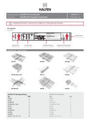
<strong>HIT</strong>-HP MV-…-COR — High Performance<br />
For cantilevered outside corner<br />
balconies to be built out of Standard<br />
Elements with same load bearing<br />
capacity and a corner fi ller;<br />
insulation thickness 80 mm.<br />
→ page 26<br />
<strong>HIT</strong>-SP MV-…-COR — Superior Performance e<br />
Type-tested<br />
For cantilevered outside corner<br />
balconies to be built out of Standard<br />
Elements with same load bearing<br />
capacity and a corner fi ller;<br />
insulation thickness 120 mm.<br />
→page 26<br />
6<br />
Chapter 1 Thermally insulated connections for cantilevered balcony slabs<br />
<strong>HIT</strong>-HP MV — High Performance<br />
Transfers bending moments and shear<br />
forces; insulation thickness 80 mm.<br />
→ page 10<br />
<strong>HIT</strong>-HP MV-…-ES — High Performance<br />
Product type for element slabs<br />
Transfers bending moments and shear<br />
forces; insulation thickness 80 mm.<br />
→ page 10<br />
<strong>HIT</strong>-SP MV — Superior Performance<br />
Transfers bending moments and shear<br />
forces; insulation thickness 120 mm.<br />
→ page 10<br />
<strong>HIT</strong>-SP MV-…-ES — Superior Performance<br />
Product type for element slabs<br />
Transfers bending moments and shear<br />
forces; insulation thickness 120 mm.<br />
→ page 10<br />
Type-tested<br />
Balcony<br />
Type-tested<br />
Balcony<br />
Type-tested<br />
Balcony<br />
Type-tested<br />
Balcony<br />
Thermally insulated connections for cantilevered corner balconies<br />
Type-tested<br />
<br />
Main slab<br />
<br />
Main slab<br />
<br />
Main slab<br />
<br />
Main slab<br />
<br />
<br />
<strong>HIT</strong>-HP MV<br />
<strong>HIT</strong>-HP MV-ES<br />
<strong>HIT</strong>-SP MV<br />
<strong>HIT</strong>-SP MV-ES<br />
<strong>HIT</strong>-HP MV<br />
<strong>HIT</strong>-HP MV-ES<br />
Balcony<br />
<strong>HIT</strong>-SP MV<br />
<strong>HIT</strong>-SP MV-ES<br />
Balcony<br />
<strong>NEW</strong>!<br />
<strong>HIT</strong>-HP MV<br />
<strong>HIT</strong>-HP MV-ES<br />
<strong>HIT</strong>-HP FK-COR<br />
corner filler<br />
<strong>HIT</strong>-HP MV<br />
with cv = 50<br />
<strong>HIT</strong>-HP MV-ES<br />
with cv = 50<br />
<strong>HIT</strong>-SP MV<br />
<strong>HIT</strong>-SP MV-ES<br />
<strong>HIT</strong>-SP FK-COR<br />
corner filler<br />
<strong>HIT</strong>-SP MV<br />
with cv = 50<br />
<strong>HIT</strong>-SP MV-ES<br />
with cv = 50<br />
© 2013 <strong>HALFEN</strong> · <strong>HIT</strong> 13-E · www.halfen.com
<strong>HALFEN</strong> <strong>HIT</strong> <strong>INSULATED</strong> <strong>CONNECTION</strong><br />
Product Overview<br />
Chapter 2 Thermally insulated connections for cantilevered balcony slabs<br />
<strong>HIT</strong>-BX±Q, <strong>HIT</strong>-BF±Q<br />
Transfer of bending moments and<br />
shear forces in both directions.<br />
→page 37<br />
<strong>HIT</strong>-BQ<br />
Transfer of shear forces only.<br />
→ page 57<br />
© 2013 <strong>HALFEN</strong> · <strong>HIT</strong> 13-E · www.halfen.com<br />
Type-tested<br />
Balcony<br />
Balcony<br />
Balcony<br />
Main slab<br />
Main slab<br />
<strong>HIT</strong>-BX±Q <strong>HIT</strong>-BX±Q<br />
<strong>HIT</strong>-BQ<br />
<strong>HIT</strong>-BX±Q <strong>HIT</strong>-BX±Q<br />
Balcony<br />
Chapter 3 Thermally insulated connections for cantilevered balcony slabs with height offset or wall connections<br />
<strong>HIT</strong>-BX-HV, <strong>HIT</strong>-BF-HV<br />
Height off set, balcony lower<br />
than main slab. Transfer of bending<br />
moments and shear forces.<br />
→page 49<br />
<strong>HIT</strong>-BX-BH, <strong>HIT</strong>-BF-BH<br />
Height off set, balcony higher than<br />
main slab. Transfer of bending<br />
moments and shear forces.<br />
→page 49<br />
<strong>HIT</strong>-BX-WU, <strong>HIT</strong>-BF-WU<br />
Downward wall connection.<br />
Transfer of bending moments<br />
and shear forces.<br />
→page 49<br />
<strong>HIT</strong>-BX-WO, <strong>HIT</strong>-BF-WO<br />
Upward wall connection.<br />
Transfer of bending moments<br />
and shear forces.<br />
→page 49<br />
Balcony<br />
Balcony<br />
Balcony<br />
Main slab<br />
Chapter 4 Thermally insulated connections for simply-supported balcony slabs on columns<br />
Type-tested<br />
Wall<br />
Wall<br />
Wall<br />
<strong>HIT</strong>-BX-HV<br />
<strong>HIT</strong>-BF-HV<br />
Balcony<br />
<strong>HIT</strong>-BX-BH<br />
<strong>HIT</strong>-BF-BH<br />
Balcony<br />
<strong>HIT</strong>-BX-WU<br />
<strong>HIT</strong>-BF-WU<br />
Balcony<br />
<strong>HIT</strong>-BX-WO<br />
<strong>HIT</strong>-BF-WO<br />
Balcony<br />
<strong>HIT</strong>-BQ<br />
Balcony<br />
7<br />
1<br />
HP MV / SP MV<br />
…-MV-COR<br />
2<br />
BX±Q / BF±Q<br />
BX±Q- / B F±Q - MOD<br />
3<br />
BX- / BF-<br />
· HV · BH · WO · WU<br />
4<br />
ST / WT FT / OT / AT BD HT / S - Anchor BQ / VT<br />
5<br />
6<br />
7<br />
8<br />
9<br />
Technical<br />
Information
1<br />
HP MV / SP MV<br />
…-MV-COR<br />
2<br />
BX±Q / BF±Q<br />
BX±Q- / B F±Q - MOD<br />
3<br />
BX- / BF-<br />
· HV · BH · WO · WU<br />
4<br />
ST / WT FT / OT / AT BD HT / S - Anchor BQ / VT<br />
5<br />
6<br />
7<br />
8<br />
9<br />
Technical<br />
Information<br />
<strong>HALFEN</strong> <strong>HIT</strong> <strong>INSULATED</strong> <strong>CONNECTION</strong><br />
Product Overview<br />
<strong>HIT</strong>-HT<br />
Absorbs horizontal forces parallel and/<br />
or perpendicular to the insulation line.<br />
→ page 67<br />
8<br />
Chapter 4 Thermally insulated connections for simply-supported balcony slabs on columns<br />
<strong>HIT</strong>-±BQ<br />
Transfer of positive and negative shear<br />
forces.<br />
→page 57<br />
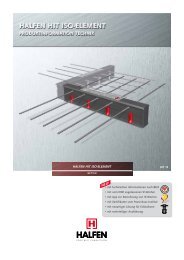
<strong>HIT</strong>-VT<br />
Unrestrained connection of balcony<br />
slabs subjected only to shear loads.<br />
→page 62<br />
Chapter 5 Thermally insulated connections / connecting elements to absorb horizontal forces<br />
<strong>HIT</strong>-S-Anchor<br />
For planned assumed horizontal loads.<br />
→ page 70<br />
<strong>HIT</strong>-BD<br />
Transfer of positive and negative<br />
moments and shear forces.<br />
→page 71<br />
<strong>HIT</strong>-FT<br />
Forms a thermal barrier between<br />
corbelled parapet and roof slab<br />
for selective use. Unit spacing based<br />
on structural requirements.<br />
→ page 75<br />
Type-tested<br />
Balcony<br />
Type-tested<br />
Balcony<br />
Balcony<br />
Chapter 6 Thermally insulated connections for continuous slabs<br />
Type-tested<br />
Balcony<br />
Corbelled parapet<br />
Main slab<br />
Main slab<br />
Main slab<br />
Main slab<br />
Main slab<br />
Chapter 7 Thermally insulated connections for parapets and corbels<br />
Roof slab<br />
<strong>HIT</strong>-VT<br />
<strong>HIT</strong>-VT<br />
<strong>HIT</strong>-±BQ<br />
<strong>HIT</strong>-VT<br />
<strong>HIT</strong>-BQ <strong>HIT</strong>-BQ<br />
<strong>HIT</strong>-HT<br />
<strong>HIT</strong>-BD<br />
<strong>HIT</strong>-VT<br />
<strong>HIT</strong>-BD<br />
Roof slab<br />
In-situ thermal insulation<br />
Corbelled<br />
Balcony<br />
Balcony<br />
Balcony<br />
Balcony<br />
parapet<br />
<strong>HIT</strong>-FT <strong>HIT</strong>-FT <strong>HIT</strong>-FT<br />
© 2013 <strong>HALFEN</strong> · <strong>HIT</strong> 13-E · www.halfen.com
<strong>HALFEN</strong> <strong>HIT</strong> <strong>INSULATED</strong> <strong>CONNECTION</strong><br />
Product Overview<br />
Chapter 7 Thermally insulated connections for parapets and corbels<br />
<strong>HIT</strong>-OT<br />
Forms a thermal barrier between<br />
corbel and main slab for selective use.<br />
Unit spacing based on structural<br />
requirements.<br />
→page 75<br />
<strong>HIT</strong>-AT<br />
Forms a thermal barrier between<br />
parapet and roof slab for selective use.<br />
Unit spacing based on structural<br />
requirements.<br />
→page 75<br />
Chapter 8 Thermally insulated connections for shear walls and beams<br />
<strong>HIT</strong>-ST<br />
Insulates cantilevered<br />
beams. Transfers high<br />
bending moments<br />
and shear forces in<br />
selected areas<br />
→ page 79<br />
<strong>HIT</strong>-WT<br />
Insulates storey-high,<br />
cantilevered shear<br />
walls. Transfers<br />
bending moments<br />
and shear forces in<br />
selected areas mainly<br />
in vertical direction.<br />
→ page 79<br />
© 2013 <strong>HALFEN</strong> · <strong>HIT</strong> 13-E · www.halfen.com<br />
Beam<br />
External shear wall<br />
Corbel<br />
Parapet<br />
Chapter 9 Building physics, technical information<br />
Information on thermal insulation, fi re protection and noise reduction,<br />
planning aid, information on design software, tender specifi cations<br />
→ page 83<br />
Main slab<br />
Roof slab<br />
Shear wall<br />
Internal shear wall<br />
<strong>HIT</strong>-AT <strong>HIT</strong>-AT<br />
In-situ thermal insulation<br />
<strong>HIT</strong>-AT<br />
<strong>HIT</strong>-ST<br />
Main slab<br />
In-situ thermal insulation<br />
<strong>HIT</strong>-ST<br />
Balcony<br />
Balken Beam Balken Beam<br />
Shear<br />
Wall<br />
Corbel<br />
Roof slab<br />
Parapet<br />
Main slab<br />
In-situ thermal insulation<br />
Main slab<br />
In-situ thermal insulation<br />
Balcony<br />
Shear<br />
Wall<br />
9<br />
1<br />
HP MV / SP MV<br />
…-MV-COR<br />
2<br />
BX±Q / BF±Q<br />
BX±Q- / B F±Q - MOD<br />
3<br />
BX- / BF-<br />
· HV · BH · WO · WU<br />
4<br />
ST / WT FT / OT / AT BD HT / S - Anchor BQ / VT<br />
5<br />
6<br />
7<br />
8<br />
9<br />
Technical<br />
Information
1<br />
HP MV / SP MV<br />
…-MV-COR<br />
2<br />
BX±Q / BF±Q<br />
BX±Q- / B F±Q - MOD<br />
3<br />
BX- / BF-<br />
· HV · BH · WO · WU<br />
4<br />
ST / WT FT / OT / AT BD HT / S - Anchor BQ / VT<br />
5<br />
6<br />
7<br />
8<br />
9<br />
Technical<br />
Information<br />
<strong>HALFEN</strong> <strong>HIT</strong> <strong>INSULATED</strong> <strong>CONNECTION</strong> HIGH AND SUPERIOR PERFORMANCE<br />
Material Specification and Test Certificates<br />
Material specification<br />
<strong>HALFEN</strong> <strong>HIT</strong> Insulated connections DIBt Berlin, National Technical Approval No. Z-15.7-293<br />
• Tension bars<br />
Test certificates<br />
10<br />
<br />
Flash butt welded bar connection according to the National Technical Approval<br />
No. Z-15.7-293, consisting of a combination of two reinforcing steel bars B500B<br />
(BSt 500S ) according to DIN 488 and a stainless bar steel of strength class S 690<br />
according to National Technical Approval No. Z-30.3-6<br />
• Compression shear bearings High-performance mortar with increased compressive and tensile strength<br />
as well as optimized thermal conductivity according to National Technical Approval<br />
No. Z-15.7-293<br />
• Casings Rigid PVC according to DIN EN ISO 1163<br />
• Insulating material Thermally insulating fi re protection material – mineral wool (WLG 035) of<br />
Building Material Class A1, non-fl ammable insulation according to DIN 4102-14 or<br />
Euro Class A1 according to DIN EN 13501-1<br />
Connecting components<br />
• Concrete Suited for concrete strengths ≥ C20/25<br />
• On-site reinforcement Reinforcing steel B500B (BSt 500)<br />
• National Technical Approval<br />
• Type statics<br />
DIBt Berlin, National Technical<br />
Approval No. Z-15.7-293<br />
- <strong>HALFEN</strong> <strong>HIT</strong> Insulated connection <strong>HIT</strong>-HP/<br />
<strong>HIT</strong>-SP with compression shear bearings<br />
acc. to DIN 1045-1 / DIN EN 1992-1-1/NA<br />
- including fi re protection<br />
- including thermic values<br />
Type-tested by the<br />
Landesgewerbe anstalt Bayern,<br />
Test-No. S-Ü 100358<br />
- Type test report no. 1 / no. 2 / no. 3<br />
• Passive House Institute Certifi cation Certifi cation valid for slab thicknesses from<br />
180 mm to 240 mm<br />
• Noise reduction<br />
• RAL Quality Mark<br />
Noise reduction according to<br />
DIN EN ISO 140-6, verifi ed by the<br />
MFPA Leipzig (P 4.2/09-413)<br />
RAL German Institut for Quality<br />
Assurance and Certifi cation,<br />
RAL Quality Mark Anchoring- and<br />
Reinforcement technology RAL-GZ 658/2<br />
Approvals and type tests on the internet<br />
The approvals and type tests can be found at<br />
halfen.de/Service/Brochures, or simply scan the code and<br />
then select the document.<br />
N a t i o n a l T e c h n i c a l A p p r o v a l<br />
values<br />
Thermal bridge reduced<br />
Construction<br />
RAL-GZ 658/2<br />
© 2013 <strong>HALFEN</strong> · <strong>HIT</strong> 13-E · www.halfen.com
<strong>HALFEN</strong> <strong>HIT</strong> <strong>INSULATED</strong> <strong>CONNECTION</strong> HIGH AND SUPERIOR PERFORMANCE<br />
Introduction <strong>HIT</strong>-HP MV, <strong>HIT</strong>-SP MV<br />
<strong>HIT</strong>-HP MV / <strong>HIT</strong>-SP MV:<br />
Balcony connection for cantilevered balcony slabs Transfers bending moments and shear forces<br />
Standard design:<br />
<strong>HIT</strong>-HP MV – High Performance with insulation thickness 80 mm<br />
<strong>HIT</strong>-SP MV – Superior Performance with insulation thickness 120 mm<br />
Multi-part-design:<br />
<strong>HIT</strong>-HP MV-ES – High Performance for element slabs<br />
<strong>HIT</strong>-SP MV-ES – Superior Performance for element slabs<br />
© 2013 <strong>HALFEN</strong> · <strong>HIT</strong> 13-E · www.halfen.com<br />
B<br />
B<br />
<strong>HIT</strong>-HP MV / <strong>HIT</strong>-SP MV<br />
<strong>HIT</strong>-HP MV<br />
<strong>HIT</strong>-HP MV<br />
<strong>HIT</strong>-SP MV<br />
MV<br />
<strong>HIT</strong>-HP MV-...-ES<br />
<strong>HIT</strong>-SP MV-...-ES<br />
<br />
<br />
Balcony Main slab<br />
Available as:<br />
One-meter element or in 0.25 or 0.50 m units<br />
Balcony<br />
Figure: Cantilevered balcony<br />
<strong>HIT</strong>-SP MV-...-ES / <strong>HIT</strong>-SP MV-...-ES<br />
Balcony<br />
Main<br />
slab<br />
Available as:<br />
One-meter element or in 0.25 or 0.50 m units<br />
Chapter 1 “<strong>HIT</strong>-HP MV, <strong>HIT</strong>-SP MV“ – Overview Page<br />
Product description <strong>HIT</strong>-HP MV, <strong>HIT</strong>-SP MV 12<br />
Product variations <strong>HIT</strong>-HP MV, <strong>HIT</strong>-SP MV 13<br />
Basics on load bearing capacity <strong>HIT</strong>-HP MV, <strong>HIT</strong>-SP MV 14<br />
Load ranges and load bearing capacity values <strong>HIT</strong>-HP MV 15<br />
Load ranges and load bearing capacity values <strong>HIT</strong>-SP MV 20<br />
Product type for element slabs <strong>HIT</strong>-HP MV-ES, <strong>HIT</strong>-SP MV-ES 24<br />
Elements for cantilevered corner balconies <strong>HIT</strong>-HP MV-COR, <strong>HIT</strong>-SP MV-COR 26<br />
Cantilever lengths, usability 28<br />
On-site connecting reinforcement, installation diagram 29<br />
Joint spacings and edge distances, mixed installation 33<br />
Camber 34<br />
11<br />
1<br />
HP MV / SP MV<br />
…-MV-COR<br />
2<br />
BX±Q / BF±Q<br />
BX±Q- / B F±Q - MOD<br />
3<br />
BX- / BF-<br />
· HV · BH · WO · WU<br />
4<br />
ST / WT FT / OT / AT BD HT / S - Anchor BQ / VT<br />
5<br />
6<br />
7<br />
8<br />
9<br />
Technical<br />
Information
1<br />
HP MV / SP MV<br />
…-MV-COR<br />
2<br />
BX±Q / BF±Q<br />
BX±Q- / B F±Q - MOD<br />
3<br />
BX- / BF-<br />
· HV · BH · WO · WU<br />
4<br />
ST / WT FT / OT / AT BD HT / S - Anchor BQ / VT<br />
5<br />
6<br />
7<br />
8<br />
9<br />
Technical<br />
Information<br />
<strong>HALFEN</strong> <strong>HIT</strong> <strong>INSULATED</strong> <strong>CONNECTION</strong> HIGH AND SUPERIOR PERFORMANCE<br />
Product Description <strong>HIT</strong>-HP MV, <strong>HIT</strong>-SP MV<br />
Cross-sections<br />
<strong>HIT</strong>-HP MV — High Performance<br />
12<br />
160 ≤ h ≤ 250 160 ≤ h ≤ 250<br />
cv,TB =<br />
cv,TB =<br />
30 / 35 / 50<br />
30 / 35 / 50<br />
<strong>HIT</strong>-SP MV — Superior Performance<br />
Dimensions in mm<br />
s R,CSB<br />
s CSB s CSB s CSB<br />
s R,CSB<br />
s R,TB<br />
s TB s TB s TB s TB<br />
s R,TB<br />
715 80<br />
715<br />
715<br />
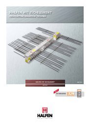
Tension bars Ø 12 mm or 10.5 mm in the joint<br />
Compression shear bearings CSB<br />
Tension bar box<br />
Compression shear bearings box<br />
B<br />
12 12<br />
10.5 10.5<br />
lTB = 1510<br />
l TB = 1550<br />
For more detailed information on the element slab types <strong>HIT</strong>-HP MV-…-ES / <strong>HIT</strong>-SP MV-…-ES → page 24<br />
120<br />
80 / 120 80 / 120 80 / 120<br />
15 15<br />
s R,CSB<br />
sCSB sTB sTB s R,CSB<br />
s R,TB<br />
s R,TB<br />
715<br />
B<br />
TB-Box <br />
CSB-Box <br />
TB-Box <br />
CSB-Box <br />
Top view (examples)<br />
Element width B = 1.00 m Element width B = 0.50 m Element width B = 0.25 m<br />
<br />
s R,CSB<br />
s CSB<br />
s R,CSB<br />
s R,TB<br />
s TB<br />
s R,TB<br />
B<br />
For a top view of other units with<br />
dimensions, please refer to the type statics<br />
data sheets; available at www.halfen.de.<br />
© 2013 <strong>HALFEN</strong> · <strong>HIT</strong> 13-E · www.halfen.com
<strong>HALFEN</strong> <strong>HIT</strong> <strong>INSULATED</strong> <strong>CONNECTION</strong> HIGH AND SUPERIOR PERFORMANCE<br />
Product Variations <strong>HIT</strong>-HP MV, <strong>HIT</strong>-SP MV<br />
Components and configuration of upper and lower parts<br />
Number of components for different element widths B [cm]<br />
Element width B [cm] 25 50 100<br />
No. of tension bars nTB 1 ... 3 2 ... 7 4 ... 14<br />
No. of compression shear bearings nCSB 1 … 2 2 … 5 4 … 10<br />
Element thickness h [cm] 16 … 25 16 … 25 16 … 25<br />
Concrete cover cv,TB [mm] 30 / 35 / 50 30 / 35 / 50 30 / 35 / 50<br />
Configuration of tension bar box (TB-Box)<br />
<br />
The basic type of tension bar box (TB-Box) and compression shear bearing box (CSB-Box) of <strong>HALFEN</strong> Insulated connections<br />
<strong>HIT</strong>-HP MV and <strong>HIT</strong>-SP MV are listed in the following tables. The concrete cover of the compression shear bearings CSB<br />
to the component surface (lower side) is always c nom,CSB = 15 mm.<br />
Element width B [cm] 25 50<br />
No. of tension bars nTB 1 2 3 2 3 4 5 6 7<br />
Edge distance tension bars sR,TB [mm] 125 62.5 50 125 125 62.5 100 50 55<br />
Centre distance tension bars sTB [mm] — 125 75 250 125 125 75 80 65<br />
Tension bar length <strong>HIT</strong>-HP MV lTB [mm] 1510 1510<br />
Tension bar length <strong>HIT</strong>-SP MV lTB [mm] 1550 1550<br />
Configuration of compression shear bearing box (CSB-Box)<br />
Element width B [cm] 25 50<br />
No. of compression shear bearings nCSB 1 2 2 3 4 5<br />
Edge distance CSB sR,CSB [mm] 125 82.5 125 125 100 100<br />
Centre distance CSB sCSB [mm] — 85 250 125 100 75<br />
Configuration of tension bar box (TB-Box)<br />
Element width B [cm] 100<br />
No. of tension bars nTB 4 5 6 7 8 9 10 11 12 13 14<br />
Edge distance tension bars sR,TB [mm] 125 150 125 125 62.5 100 50 50 60 50 77.5<br />
Centre distance tension bars sTB [mm] 250 175 150 125 125 100 100 90 80 75 65<br />
Tension bar length <strong>HIT</strong>-HP MV lTB [mm] 1510<br />
Tension bar length <strong>HIT</strong>-SP MV lTB [mm] 1550<br />
Configuration of compression shear bearing box (CSB-Box)<br />
Element width B [cm] 100<br />
No. of compression shear bearings nCSB 4 5 6 7 8 9 10<br />
Edge distance CSB sR,CSB [mm] 125 100 125 125 150 100 81.5<br />
Centre distance CSB sCSB [mm] 250 200 150 125 100 100 93<br />
© 2013 <strong>HALFEN</strong> · <strong>HIT</strong> 13-E · www.halfen.com<br />
13<br />
1<br />
HP MV / SP MV<br />
…-MV-COR<br />
2<br />
BX±Q / BF±Q<br />
BX±Q- / B F±Q - MOD<br />
3<br />
BX- / BF-<br />
· HV · BH · WO · WU<br />
4<br />
ST / WT FT / OT / AT BD HT / S - Anchor BQ / VT<br />
5<br />
6<br />
7<br />
8<br />
9<br />
Technical<br />
Information
1<br />
HP MV / SP MV<br />
…-MV-COR<br />
2<br />
BX±Q / BF±Q<br />
BX±Q- / B F±Q - MOD<br />
3<br />
BX- / BF-<br />
· HV · BH · WO · WU<br />
4<br />
ST / WT FT / OT / AT BD HT / S - Anchor BQ / VT<br />
5<br />
6<br />
7<br />
8<br />
9<br />
Technical<br />
Information<br />
<strong>HALFEN</strong> <strong>HIT</strong> <strong>INSULATED</strong> <strong>CONNECTION</strong> HIGH AND SUPERIOR PERFORMANCE<br />
Basics on Load Bearing Capacity<br />
Load bearing behaviour of <strong>HIT</strong>-HP MV and <strong>HIT</strong>-SP MV<br />
Cutting edge technology – made by <strong>HALFEN</strong><br />
As a world fi rst, the <strong>HALFEN</strong> Insulated cantilever slab connections<br />
<strong>HIT</strong>-HP MV and <strong>HIT</strong>-SP MV feature the innovative<br />
and patented structural C S B Compression Shear Bearing<br />
system. The load bearing compression bearings and stainless<br />
steel shear bars, that have been used up to now, have been<br />
fully replaced by the innovative technology of using compression<br />
shear bearings made of ultra-high strength fi bre-reinforced<br />
mortar. The C S B act as a compression shear zone<br />
and they transfer the compressive and shear forces in the<br />
<strong>HIT</strong>-HP MV and <strong>HIT</strong>-SP MV insulating elements.<br />
Integrated safety concept<br />
For the fi rst time, the complete verifi cation and design concept<br />
for balcony connections has been incorporated into a<br />
National Technical Approval. Annex 5 of the Approval Z-15.7-<br />
293 includes verifi cation of the moment/shear force interaction<br />
of the C S B as well as verifi cation against concrete edge<br />
failure to ensure load transfer into adjacent components. This<br />
includes all respective verifi cations for slab connection regarding<br />
the force transmission. Consequently, time-consuming additional<br />
verifi cations such as the limitation of the concrete<br />
compressive strut are no longer necessary. The structural engineer<br />
is provided with maximum planning reliability.<br />
In addition to the technical approval you will of course fi nd<br />
the LGA Würzburg type test available for download on the<br />
<strong>HALFEN</strong> website. The type test includes the transferable<br />
bending moments M Rd and shear forces V Rd of normal load<br />
ranges for concrete strength classes C20/25, C25/30 and<br />
C30/37 as well as for the concrete covers for tension bars<br />
with c v = 30 mm, 35 mm and 50 mm.<br />
The load bearing capacities of selected elements are illustrated<br />
in more detail on pages 16 to 19 for <strong>HIT</strong>-HP MV and on<br />
pages 21 to 23 for <strong>HIT</strong>-SP MV. The component resistances of<br />
the elements with a width of 1.00 m, 0.50 m and 0.25 m are<br />
each stated per running meter. This allows easy selection and<br />
planning reliability for any connector length. With diff erent<br />
concrete strength classes on the balcony and the main slab,<br />
the lower concrete strength is decisive when selecting load<br />
range capacity level.<br />
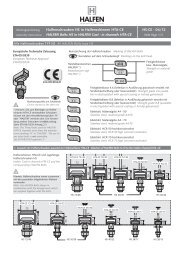
The load bearing capacity of the elements is characterized<br />
by a moment/shear force interaction curve (see diagram).<br />
14<br />
V<br />
V Rd,1<br />
V Rd,2<br />
M Ed<br />
V Ed ≥ 0.15<br />
precise verification<br />
simplifyingly calculated<br />
by linear interpolation<br />
MRd,1<br />
MRd,2<br />
M<br />
<br />
The structural behaviour of <strong>HIT</strong> Elements<br />
If the maximum vertical force bearing capacity V Rd,1 is not<br />
fully exploited, the C S B technology provides the opportunity<br />
to increase the moment bearing capacity so that it exceeds<br />
M Rd,1. MRd,2 is the maximum moment bearing capacity with<br />
the corresponding vertical force bearing capacity V Rd,2.<br />
This load bearing behaviour is considered in the <strong>HIT</strong><br />
software. This software selects the optimum load range of<br />
the <strong>HIT</strong> elements.<br />
<strong>HALFEN</strong> software is available for download at www.halfen.de.<br />
Moment/shear force interaction at the cantilever slab connection<br />
With C S B technology shear forces of up to 160 kN per meter<br />
can be transferred safely and in accordance with the National<br />
Technical Approval (applies to slab thickness ≥ 160 mm).<br />
To ensure these high load bearing capacities are kept within<br />
the application range for cantilever slab connection, the following<br />
ratio of the external force variables must be observed:<br />
MEd<br />
V Ed<br />
≥ 0.15<br />
© 2013 <strong>HALFEN</strong> · <strong>HIT</strong> 13-E · www.halfen.com
<strong>HALFEN</strong> <strong>HIT</strong> <strong>INSULATED</strong> <strong>CONNECTION</strong> HIGH AND SUPERIOR PERFORMANCE<br />
Product Variations <strong>HIT</strong>-HP MV<br />
Load ranges <strong>HIT</strong>-HP MV<br />
The respective load range results from the corresponding combination of TB- and CSB-Box.<br />
The combinations of TB- and CSB-Box illustrated in the following table are possible and type-tested.<br />
Load range <strong>HIT</strong>-HP MV: possible combinations of upper and lower parts<br />
Element width B = 25 cm<br />
Number of<br />
compression shear bearings nCSB<br />
Element width B = 50 cm<br />
Number of<br />
compression shear bearings nCSB<br />
Element width B = 100 cm<br />
Number of<br />
compression shear bearings nCSB<br />
×<br />
Basic types<br />
no. of tension bars nTB 1 2 3<br />
1 × ×<br />
2 × × ×<br />
no. of tension bars nTB<br />
2 3 4 5 6 7<br />
2 × × ×<br />
3 × × × ×<br />
4 × × × × × ×<br />
5 × × × × ×<br />
The complete type tested load class range for concrete grades C20/25, C25/30<br />
and C30/37 is available for download at www.halfen.de.<br />
<strong>HIT</strong>- HP MV - 07 05 - 20 - 100 - 35 - ES<br />
<strong>HIT</strong>- HP MV - 0404 - 18 - 050 - 50 - ES<br />
<strong>HIT</strong>- HP MV - 0202 - 18 - 025 - 30 - ES<br />
Concrete cover [mm] 30 35 50<br />
Possible slab thickness h [cm] 16 – 25 16 – 25 18 – 25<br />
<br />
no. of tension bars nTB 4 5 6 7 8 9 10 11 12 13 14<br />
4 × × × × × ×<br />
5 × × × × × × × ×<br />
6 × × × × × × × × × ×<br />
7 × × × × × × × × × × ×<br />
8 × × × × × × × × × × ×<br />
9 × × × × × × × × × ×<br />
10 × × × × × × × ×<br />
The load bearing capacities values for the elements highlighted in blue can be found on pages 16–19.<br />
Ordering example:<br />
• Product group - type → overview page 12<br />
• Load type → tables ff. page 16<br />
• Number of tension bars → tables page 13<br />
• No. of compr. shear bearings CSB → tables p. 13<br />
• Element thickness → overview below<br />
• Element width → overview page 13<br />
• Concrete cover → table page 13<br />
Possible slab thickness h<br />
© 2013 <strong>HALFEN</strong> · <strong>HIT</strong> 13-E · www.halfen.com<br />
• for element slab design only<br />
80<br />
Custom designs are available on request.<br />
For further details, please contact us.<br />
→ see back cover for contact details<br />
15<br />
1<br />
HP MV / SP MV<br />
…-MV-COR<br />
2<br />
BX±Q / BF±Q<br />
BX±Q- / B F±Q - MOD<br />
3<br />
BX- / BF-<br />
· HV · BH · WO · WU<br />
4<br />
ST / WT FT / OT / AT BD HT / S - Anchor BQ / VT<br />
5<br />
6<br />
7<br />
8<br />
9<br />
Technical<br />
Information
1<br />
HP MV / SP MV<br />
…-MV-COR<br />
2<br />
BX±Q / BF±Q<br />
BX±Q- / B F±Q - MOD<br />
3<br />
BX- / BF-<br />
· HV · BH · WO · WU<br />
4<br />
ST / WT FT / OT / AT BD HT / S - Anchor BQ / VT<br />
5<br />
6<br />
7<br />
8<br />
9<br />
Technical<br />
Information<br />
<strong>HALFEN</strong> <strong>HIT</strong> <strong>INSULATED</strong> <strong>CONNECTION</strong> HIGH PERFORMANCE<br />
16<br />
vRd<br />
Shear<br />
capacity<br />
m Rd<br />
As<br />
<br />
Load Bearing Capacity Values According to DIN 1045-1 / EC2 – Element Widths B = 1.00 / 0.50 / 0.25m<br />
Load bearing capacity values for <strong>HIT</strong>-HP MV<br />
Moment bearing<br />
capacity<br />
B = 1.00<br />
B = 0.50<br />
HP MV-0404<br />
HP MV-0202<br />
HP MV-0504<br />
—<br />
HP MV-0604<br />
HP MV-0302<br />
HP MV-0804<br />
HP MV-0402<br />
HP MV-0805<br />
—<br />
B = 0.25 HP MV-0101 — — HP MV-0201 —<br />
Concrete cover [mm] 30 35 50 Concrete strength: C20/25 / ≥ C25/30<br />
Design values<br />
m Rd [kNm/m]<br />
for slab thickness<br />
[mm]<br />
Shear capacity in one direction<br />
B = 1.00 m HP MV-0404 HP MV-0504 HP MV-0604 HP MV-0804 HP MV-0805<br />
B = 0.50 m HP MV-0202 — HP MV-0302 HP MV-0402 —<br />
B = 0.25 m HP MV-0101 — — HP MV-0201 —<br />
Design values vRd [kN/m] 64.0 64.0 80.0 80.0<br />
Moment capacity for all element widths<br />
160 16.9 17.4 20.0 20.8 22.7 23.9 24.7 28.7 29.5 31.2<br />
160 180 17.9 18.4 21.3 22.1 24.2 25.4 26.4 30.6 31.5 33.2<br />
170 18.9 19.4 22.5 23.3 25.6 26.8 28.0 32.6 33.5 35.2<br />
170 190 19.9 20.4 23.7 24.5 27.1 28.3 29.7 34.6 35.4 37.1<br />
180 20.8 21.4 24.9 25.8 28.6 29.8 31.4 36.5 37.4 39.1<br />
180 200 21.8 22.4 26.2 27.0 30.1 31.3 33.1 38.5 39.4 41.1<br />
190 22.8 23.3 27.4 28.2 31.5 32.7 34.8 40.4 41.3 43.0<br />
190 210 23.8 24.3 28.6 29.5 33.0 34.2 36.5 42.4 43.3 45.0<br />
200 24.8 25.3 29.9 30.7 34.5 35.7 38.2 44.3 45.3 47.0<br />
200 220 25.8 26.3 31.1 31.9 36.0 37.2 39.9 46.3 47.3 48.9<br />
210 26.7 27.3 32.3 33.1 37.4 38.6 41.6 48.2 49.2 50.9<br />
210 230 27.7 28.3 33.6 34.4 38.9 40.1 43.3 50.2 51.2 52.9<br />
220 28.7 29.2 34.8 35.6 40.4 41.6 45.0 52.1 53.2 54.8<br />
220 240 29.7 30.2 36.0 36.8 41.9 43.1 46.7 54.1 55.1 56.8<br />
230 30.7 31.2 37.2 38.1 43.4 44.5 48.3 56.1 57.1 58.8<br />
230 250 31.7 32.2 38.5 39.3 44.8 46.0 50.0 58.0 59.1 60.7<br />
240 32.6 33.2 39.7 40.5 46.3 47.5 51.7 60.0 61.0 62.7<br />
240 33.6 34.2 40.9 41.8 47.8 49.0 53.4 61.9 63.0 64.7<br />
250 34.6 35.1 42.2 43.0 49.3 50.4 55.1 63.9 65.0 66.6<br />
250 35.6 36.1 43.4 44.2 50.7 51.9 56.8 65.8 66.9 68.6<br />
On-site reinforcement A s,req (→ page 27)<br />
Edge frame direct support Ø 6 / 25 cm<br />
Note: Concrete strength C20/25 / ≥ C25/30<br />
34.6 36.2<br />
Suspension reinforcement indirect support Ø 6 / 12.5 cm Ø 6 / 10 cm<br />
All necessary verifi cations including verifying concrete strut shear<br />
pressure have been already considered.<br />
80<br />
Note:<br />
<strong>HALFEN</strong> <strong>HIT</strong> software is available to<br />
calculate the connections for your planned<br />
balcony designs; download from<br />
www.halfen.de.<br />
© 2013 <strong>HALFEN</strong> · <strong>HIT</strong> 13-E · www.halfen.com
<strong>HALFEN</strong> <strong>HIT</strong> <strong>INSULATED</strong> <strong>CONNECTION</strong> HIGH PERFORMANCE<br />
vRd<br />
m Rd<br />
As<br />
<br />
Load Bearing Capacity Values According to DIN 1045-1 / EC2 – Element Widths B = 1.00 / 0.50 / 0.25m<br />
Load bearing capacity values for <strong>HIT</strong>-HP MV<br />
Shear<br />
capacity<br />
Moment bearing<br />
capacity<br />
B = 1.00 m<br />
B = 0.50 m<br />
HP MV-0506<br />
—<br />
HP MV-0606<br />
HP MV-0303<br />
HP MV-0806<br />
HP MV-0403<br />
HP MV-1006<br />
HP MV-0503<br />
HP MV-1106<br />
—<br />
B = 0.25 m — — — — —<br />
Concrete cover [mm] 30 35 50 Concrete strength: C20/25 / ≥ C25/30<br />
Design values<br />
m Rd [kNm/m]<br />
for slab thickness<br />
[mm]<br />
Shear capacity in one direction<br />
B = 1.00 m HP MV-0506 HP MV-0606 HP MV-0806 HP MV-1006 HP MV-1106<br />
B = 0.50 m — HP MV-0303 HP MV-0403 HP MV-0503 —<br />
B = 0.25 m — — — — —<br />
Design values vRd [kN/m] 96.0 96.0<br />
Moment bearing capacity for all element widths<br />
160 21.9 22.4 25.4 26.1 31.4 32.8 34.0 38.5 36.1 41.0<br />
160 180 23.1 23.7 26.8 27.6 33.4 34.8 36.2 41.0 38.6 43.7<br />
170 24.3 24.9 28.3 29.1 35.4 36.8 38.5 43.4 41.0 46.4<br />
170 190 25.6 26.1 29.8 30.6 37.3 38.7 40.7 45.9 43.4 49.1<br />
180 26.8 27.3 31.3 32.1 39.3 40.7 42.9 48.4 45.9 51.8<br />
180 200 28.0 28.6 32.7 33.5 41.3 42.7 45.1 50.8 48.3 54.5<br />
190 29.3 29.8 34.2 35.0 43.2 44.7 47.3 53.3 50.7 57.2<br />
190 210 30.5 19.0 35.7 36.5 45.2 46.6 49.5 55.7 53.2 59.9<br />
200 31.7 32.3 37.2 38.0 47.2 48.6 51.7 58.2 55.6 62.6<br />
200 220 32.9 33.5 38.6 39.4 49.2 50.6 54.0 60.7 58.0 65.3<br />
210 34.2 34.7 40.1 40.9 51.1 52.5 56.2 63.1 60.5 68.0<br />
210 230 35.4 36.0 41.6 42.4 53.1 54.5 58.4 65.6 62.9 70.8<br />
220 36.6 37.2 43.1 43.9 55.1 56.5 60.6 68.0 65.3 73.5<br />
220 240 37.9 38.4 44.5 45.3 57.0 58.4 62.8 70.5 67.8 76.2<br />
230 39.1 39.6 46.0 46.8 59.0 60.4 65.0 73.0 70.2 78.9<br />
230 250 40.3 40.9 47.5 48.3 61.0 62.4 67.2 75.4 72.6 81.6<br />
240 41.6 42.1 49.0 49.8 62.9 64.3 69.5 77.9 75.1 84.3<br />
240 42.8 43.3 50.5 51.2 64.9 66.3 71.7 80.3 77.5 87.0<br />
250 44.0 44.6 51.9 52.7 66.9 68.3 73.9 82.8 80.0 89.7<br />
250 45.2 45.8 53.4 54.2 68.8 70.2 76.1 85.3 82.4 92.4<br />
On-site reinforcement A s,req (→ page 27)<br />
Edge frame direct support Ø 6 / 25 cm<br />
Suspension reinforcement indirect support Ø 8 / 15 cm<br />
All necessary verifi cations including verifying concrete strut shear<br />
pressure have been already considered.<br />
© 2013 <strong>HALFEN</strong> · <strong>HIT</strong> 13-E · www.halfen.com<br />
Note: Concrete strength C20/25 / ≥ C25/30<br />
34.6 36.2<br />
80<br />
Note:<br />
<strong>HALFEN</strong> <strong>HIT</strong> software is available to<br />
calculate the connections for your planned<br />
balcony designs; download from<br />
www.halfen.de.<br />
17<br />
1<br />
HP MV / SP MV<br />
…-MV-COR<br />
2<br />
BX±Q / BF±Q<br />
BX±Q- / B F±Q - MOD<br />
3<br />
BX- / BF-<br />
· HV · BH · WO · WU<br />
4<br />
ST / WT FT / OT / AT BD HT / S - Anchor BQ / VT<br />
5<br />
6<br />
7<br />
8<br />
9<br />
Technical<br />
Information
1<br />
HP MV / SP MV<br />
…-MV-COR<br />
2<br />
BX±Q / BF±Q<br />
BX±Q- / B F±Q - MOD<br />
3<br />
BX- / BF-<br />
· HV · BH · WO · WU<br />
4<br />
ST / WT FT / OT / AT BD HT / S - Anchor BQ / VT<br />
5<br />
6<br />
7<br />
8<br />
9<br />
Technical<br />
Information<br />
<strong>HALFEN</strong> <strong>HIT</strong> <strong>INSULATED</strong> <strong>CONNECTION</strong> HIGH PERFORMANCE<br />
18<br />
vRd<br />
m Rd<br />
Moment bearing<br />
capacity<br />
As<br />
<br />
Load Bearing Capacity Values According to DIN 1045-1 / EC2 – Element Widths B = 1.00 / 0.50 / 0.25m<br />
Load bearing capacity values for <strong>HIT</strong>-HP MV<br />
Shear<br />
capacity<br />
B = 1.00 HP MV-0607 HP MV-0807 HP MV-1107 HP MV-1207 HP MV-1407<br />
B = 0.50 — — — — —<br />
B = 0.25 — — — — —<br />
Concrete cover [mm] 30 35 50 Concrete strength: C20/25 / ≥ C25/30<br />
Design values<br />
mRd [kNm/m]<br />
for slab thickness<br />
[mm]<br />
Shear capacity in one direction<br />
B = 1.00 m HP MV-0607 HP MV-0807 HP MV-1107 HP MV-1207 HP MV-1407<br />
B = 0.50 m — — — — —<br />
B = 0.25 m — — — — —<br />
Design values vRd [kN/m] 112.0 112.0<br />
Moment bearing capacity for all element widths<br />
160 26.1 26.8 32.8 34.0 38.2 43.2 40.4 45.8 43.2 50.2<br />
160 180 27.6 28.3 34.8 36.0 40.6 45.9 43.1 48.8 46.1 53.6<br />
170 29.1 29.8 36.7 37.9 43.1 48.6 45.7 51.7 49.1 57.0<br />
170 190 30.6 31.2 38.7 39.9 45.5 51.3 48.4 54.7 52.0 60.5<br />
180 32.0 32.7 40.7 41.9 47.9 54.0 51.1 57.6 55.0 63.9<br />
180 200 33.5 34.2 42.6 43.8 50.4 56.7 53.7 60.6 58.0 67.3<br />
190 35.0 35.7 44.6 45.8 52.8 59.4 56.4 63.5 60.9 70.7<br />
190 210 36.5 37.1 46.6 47.8 55.2 62.1 59.0 66.5 63.9 74.2<br />
200 37.9 38.6 48.5 49.7 57.7 64.8 61.7 69.4 66.8 77.6<br />
200 220 39.4 40.1 50.5 51.7 60.1 67.5 64.3 72.4 69.8 81.0<br />
210 40.9 41.6 52.5 53.7 62.5 70.2 67.0 75.3 72.8 84.4<br />
210 230 42.4 43.0 54.4 55.6 65.0 72.9 69.7 78.3 75.7 87.8<br />
220 43.8 44.5 56.4 57.6 67.4 75.6 72.3 81.2 78.7 91.3<br />
220 240 45.3 46.0 58.4 59.6 69.9 78.4 75.0 84.2 81.6 94.7<br />
230 46.8 47.5 60.3 61.6 72.3 81.1 77.6 87.1 84.6 98.1<br />
230 250 48.3 48.9 62.3 63.5 74.7 83.8 80.3 90.1 87.6 101.5<br />
240 49.7 50.4 64.3 65.5 77.2 86.5 82.9 93.0 90.5 104.9<br />
240 51.2 51.9 66.3 67.5 79.6 89.2 85.6 96.0 93.5 108.4<br />
250 52.7 53.4 68.2 69.4 82.0 91.9 88.3 98.9 96.4 111.8<br />
250 54.2 54.8 70.2 71.4 84.5 94.6 90.9 101.9 99.4 115.2<br />
On-site reinforcement A s,req (→ page 27)<br />
Edge frame direct support Ø 6 / 25 cm Ø 6 / 20 cm<br />
Suspension reinforcement indirect support Ø 8 / 12.5 cm<br />
All necessary verifi cations including verifying concrete strut shear<br />
pressure have been already considered.<br />
80<br />
Note: Concrete strength C20/25 / ≥ C25/30<br />
34.6 36.2<br />
Note:<br />
<strong>HALFEN</strong> <strong>HIT</strong> software is available to<br />
calculate the connections for your planned<br />
balcony designs; download from<br />
www.halfen.de.<br />
© 2013 <strong>HALFEN</strong> · <strong>HIT</strong> 13-E · www.halfen.com
<strong>HALFEN</strong> <strong>HIT</strong> <strong>INSULATED</strong> <strong>CONNECTION</strong> HIGH PERFORMANCE<br />
<br />
Load Bearing Capacity Values According to DIN 1045-1 / EC2 – Element Widths B = 1.00 / 0.50 / 0.25m<br />
Load bearing capacity values for <strong>HIT</strong>-HP MV<br />
vRd<br />
Shear<br />
capacity<br />
m Rd<br />
Moment bearing<br />
capacity<br />
As<br />
B = 1.00 m HP MV-0408 HP MV-0808 HP MV-1208 HP MV-1010 HP MV-1210<br />
B = 0.50 m HP MV-0204 HP MV-0404 HP MV-0604 HP MV-0505 HP MV-0605<br />
B = 0.25 m HP MV-0102 HP MV-0202 HP MV-0302 — —<br />
Concrete cover [mm] 30 35 50 Concrete strength: C20/25 / ≥ C25/30<br />
Design values<br />
mRd [kNm/m]<br />
for slab thickness<br />
[mm]<br />
Shear capacity in one direction<br />
B = 1.00 m HP MV-0408 HP MV-0808 HP MV-1208 HP MV-1010 HP MV-1210<br />
B = 0.50 m HP MV-0204 HP MV-0404 HP MV-0604 HP MV-0505 HP MV-0605<br />
B = 0.25 m HP MV-0102 HP MV-0202 HP MV-0302 — —<br />
Design values vRd [kN/m] 116.1 120.9 128.0 128.0 160.0 160.0<br />
Moment bearing capacity for all element widths<br />
160 18.7 18.9 33.8 34.9 42.3 47.7 38.8 43.6 41.2 47.1<br />
160 180 19.7 19.9 35.8 36.8 44.9 50.7 41.1 46.0 43.6 49.8<br />
170 20.7 20.9 37.7 38.8 47.6 53.7 43.3 48.5 46.0 52.5<br />
170 190 21.6 21.9 39.7 40.8 50.3 56.6 45.5 51.0 48.4 55.2<br />
180 22.6 22.9 41.7 42.7 52.9 59.6 47.7 53.4 50.7 57.9<br />
180 200 23.6 23.9 43.7 44.7 55.6 62.5 49.9 55.9 53.1 60.6<br />
190 24.6 24.9 45.6 46.7 58.2 65.5 52.1 58.3 55.5 63.3<br />
190 210 25.6 25.8 47.6 48.6 60.9 68.4 54.3 60.8 57.9 66.0<br />
200 26.6 26.8 49.6 50.6 63.5 71.4 56.6 63.3 60.3 68.7<br />
200 220 27.5 27.8 51.5 52.6 66.2 74.3 58.8 65.7 62.7 71.4<br />
210 28.5 28.8 53.5 54.5 68.9 77.3 61.0 68.2 65.0 74.1<br />
210 230 29.5 29.8 55.5 56.5 71.5 80.2 63.2 70.6 67.4 76.8<br />
220 30.5 30.8 57.4 58.5 74.2 83.2 65.4 73.1 69.8 79.5<br />
220 240 31.5 31.7 59.4 60.4 76.8 86.1 67.6 75.6 72.2 82.2<br />
230 32.5 32.7 61.4 62.4 79.5 89.1 69.8 78.0 74.6 84.9<br />
230 250 33.4 33.7 63.3 64.4 82.1 92.0 72.0 80.5 77.0 87.6<br />
240 34.4 34.7 65.3 66.4 84.8 95.0 74.3 82.9 79.3 90.3<br />
240 35.4 35.7 67.3 68.3 87.4 97.9 76.5 85.4 81.7 93.0<br />
250 36.4 36.7 69.2 70.3 90.1 100.9 78.7 87.9 84.1 95.7<br />
250 37.4 37.6 71.2 72.3 92.8 103.8 80.9 90.3 86.5 98.4<br />
On-site reinforcement A s,req (→ page 27)<br />
Edge frame direct support Ø 6 / 25 cm Ø 6 / 20 cm Ø 6 / 15 cm<br />
Suspension reinforcement indirect support Ø 8 / 12.5 cm Ø 8 / 10 cm Ø 8 / 9 cm<br />
All necessary verifi cations including verifying concrete strut shear<br />
pressure have been already considered.<br />
© 2013 <strong>HALFEN</strong> · <strong>HIT</strong> 13-E · www.halfen.com<br />
80<br />
Note: Concrete strength C20/25 / ≥ C25/30<br />
34.6 36.2<br />
Note:<br />
<strong>HALFEN</strong> <strong>HIT</strong> software is available to<br />
calculate the connections for your planned<br />
balcony designs; download from<br />
www.halfen.de.<br />
19<br />
1<br />
HP MV / SP MV<br />
…-MV-COR<br />
2<br />
BX±Q / BF±Q<br />
BX±Q- / B F±Q - MOD<br />
3<br />
BX- / BF-<br />
· HV · BH · WO · WU<br />
4<br />
ST / WT FT / OT / AT BD HT / S - Anchor BQ / VT<br />
5<br />
6<br />
7<br />
8<br />
9<br />
Technical<br />
Information
1<br />
HP MV / SP MV<br />
…-MV-COR<br />
2<br />
BX±Q / BF±Q<br />
BX±Q- / B F±Q - MOD<br />
3<br />
BX- / BF-<br />
· HV · BH · WO · WU<br />
4<br />
ST / WT FT / OT / AT BD HT / S - Anchor BQ / VT<br />
5<br />
6<br />
7<br />
8<br />
9<br />
Technical<br />
Information<br />
<strong>HALFEN</strong> <strong>HIT</strong> <strong>INSULATED</strong> <strong>CONNECTION</strong> SUPERIOR PERFORMANCE<br />
Product Variations <strong>HIT</strong>-SP MV<br />
Load ranges for <strong>HIT</strong>-SP MV<br />
The respective load range results from the corresponding combination of TB- and CSB-Box.<br />
The combinations of TB- and CSB-Box illustrated in the following table are possible and type-tested.<br />
Load range <strong>HIT</strong>-SP MV: possible combinations of upper and lower parts<br />
Element width B = 25 cm<br />
Number of<br />
compression shear bearings nCSB<br />
Element width B = 50 cm<br />
Number of<br />
compression shear bearings nCSB<br />
Element width B = 100 cm<br />
Number of<br />
compression shear bearings nCSB<br />
20<br />
no. of tension bars nTB 1 2 3<br />
1 × ×<br />
2 × ×<br />
no. of tension bars nTB<br />
2 3 4 5 6 7<br />
2 × × ×<br />
3 × × × × ×<br />
4 × × × × ×<br />
5 × ×<br />
<strong>HIT</strong>- SP MV - 07 05 - 20 - 100 - 35 - ES<br />
<strong>HIT</strong>- SP MV - 0404 - 18 - 050 - 50 - ES<br />
<strong>HIT</strong>- SP MV - 0202 - 18 - 025 - 30 - ES<br />
<br />
no. of tension bars nTB 4 5 6 7 8 9 10 11 12 13 14<br />
4 × × × × ×<br />
5 × × × × × × ×<br />
6 × × × × × × × × ×<br />
7 × × × × × × × × ×<br />
8 × × × × × × × × ×<br />
9 × × × × × ×<br />
10 × × ×<br />
× Values for the load bearing capacities for the elements highlighted in blue → see pages 21–23.<br />
Basic types<br />
The complete, type tested load class range for concrete grades C20/25, C25/30<br />
and C30/37 is available for download at www.halfen.de.<br />
Ordering examles:<br />
• Product group - type → overview page 12<br />
• Load type → tables ff page 21<br />
• Number of tension bars → tables above<br />
• No. of compression shear units → tables above<br />
• Element thickness → overview page 13<br />
• Element width → overview page 13<br />
• Concrete cover → table page 13<br />
Available slab thickness h<br />
• Nur For element bei Ausführung slab design für Elementdecken<br />
only<br />
Concrete cover [mm] 30 35 50<br />
Available slab thickness h [cm] 16 – 25 16 – 25 18 – 25<br />
120<br />
Custom designs are available on request. For<br />
further details please contact our regional<br />
sales companies (see back cover).<br />
© 2013 <strong>HALFEN</strong> · <strong>HIT</strong> 13-E · www.halfen.com
<strong>HALFEN</strong> <strong>HIT</strong> <strong>INSULATED</strong> <strong>CONNECTION</strong> SUPERIOR PERFORMANCE<br />
vRd<br />
m Rd<br />
As<br />
Edge frame direct support Ø 6 / 25 cm<br />
<br />
Load Bearing Capacity Values According to DIN 1045-1 / EC2 – Element Widths B = 1.00 / 0.50 / 0.25m<br />
Load bearing capacity values for <strong>HIT</strong>-SP MV<br />
Shear<br />
capacity<br />
Moment bearing<br />
capacity<br />
B = 1.00 m<br />
B = 0.50 m<br />
SP MV-0404<br />
SP MV-0202<br />
SP MV-0504<br />
—<br />
SP MV-0604<br />
SP MV-0302<br />
SP MV-0804<br />
SP MV-0402<br />
SP MV-0705<br />
—<br />
B = 0.25 m SP MV-0101 — — SP MV-0201 —<br />
Concrete cover [mm] 30 35 50 Concrete strength: C20/25 / ≥ C25/30<br />
Design values<br />
m Rd [kNm/m]<br />
for slab thickness<br />
[mm]<br />
Shear capacity in one direction<br />
B = 1.00 m SP MV-0404 SP MV-0504 SP MV-0604 SP MV-0804 SP MV-0705<br />
B = 0.50 m SP MV-0202 — SP MV-0302 SP MV-0402 —<br />
B = 0.25 m SP MV-0101 — — SP MV-0201 —<br />
Design values vRd [kN/m] 61.4 64.0 62.0 64.0 56.6 64.0 27.9 48.6 74.3 80.0<br />
Moment bearing capacity for all element widths<br />
160 16.9 17.4 20.0 20.8 22.7 23.9 26.7 28.8 27.1 28.4<br />
160 180 17.9 18.4 21.3 22.1 24.2 25.4 28.7 30.8 28.8 30.1<br />
170 18.9 19.4 22.5 23.3 25.6 26.8 30.6 32.7 30.5 31.8<br />
170 190 19.9 20.4 23.7 24.5 27.1 28.3 32.6 34.7 32.3 33.6<br />
180 20.8 21.4 24.9 25.8 28.6 29.8 34.6 36.7 34.0 35.3<br />
180 200 21.8 22.4 26.2 27.0 30.1 31.3 36.5 38.6 35.7 37.0<br />
190 22.8 23.3 27.4 28.2 31.5 32.7 38.5 40.6 37.4 38.7<br />
190 210 23.8 24.3 28.6 29.5 33.0 34.2 40.5 42.6 39.1 40.4<br />
200 24.8 25.3 29.9 30.7 34.5 35.7 42.4 44.5 40.9 42.2<br />
200 220 25.8 26.3 31.1 31.9 36.0 37.2 44.4 46.5 42.6 43.9<br />
210 26.7 27.3 32.3 33.1 37.4 38.6 46.4 48.5 44.3 45.6<br />
210 230 27.7 28.3 33.6 34.4 38.9 40.1 48.3 50.4 46.0 47.3<br />
220 28.7 29.2 34.8 35.6 40.4 41.6 50.3 52.4 47.8 49.0<br />
220 240 29.7 30.2 36.0 36.8 41.9 43.1 52.3 54.4 49.5 50.8<br />
230 30.7 31.2 37.2 38.1 43.4 44.5 54.2 56.4 51.2 52.5<br />
230 250 31.7 32.2 38.5 39.3 44.8 46.0 56.2 58.3 52.9 54.2<br />
240 32.6 33.2 39.7 40.5 46.3 47.5 58.2 60.3 54.6 55.9<br />
240 33.6 34.2 40.9 41.8 47.8 49.0 60.1 62.3 56.4 57.7<br />
250 34.6 35.1 42.2 43.0 49.3 50.4 62.1 64.2 58.1 59.4<br />
250 35.6 36.1 43.4 44.2 50.7 51.9 64.1 66.2 59.8 61.1<br />
On-site reinforcement As,req (→ page 27)<br />
Suspension reinforcement indirect support Ø 6 / 12.5 cm Ø 6 / 10 cm<br />
All necessary verifi cations including verifying concrete strut shear<br />
pressure have been already considered.<br />
© 2013 <strong>HALFEN</strong> · <strong>HIT</strong> 13-E · www.halfen.com<br />
120<br />
Note: Concrete strength C20/25 / ≥ C25/30<br />
34.6 36.2<br />
Note:<br />
<strong>HALFEN</strong> <strong>HIT</strong> software is available to<br />
calculate the connections for your planned<br />
balcony designs; download from<br />
www.halfen.de.<br />
21<br />
1<br />
HP MV / SP MV<br />
…-MV-COR<br />
2<br />
BX±Q / BF±Q<br />
BX±Q- / B F±Q - MOD<br />
3<br />
BX- / BF-<br />
· HV · BH · WO · WU<br />
4<br />
ST / WT FT / OT / AT BD HT / S - Anchor BQ / VT<br />
5<br />
6<br />
7<br />
8<br />
9<br />
Technical<br />
Information
1<br />
HP MV / SP MV<br />
…-MV-COR<br />
2<br />
BX±Q / BF±Q<br />
BX±Q- / B F±Q - MOD<br />
3<br />
BX- / BF-<br />
· HV · BH · WO · WU<br />
4<br />
ST / WT FT / OT / AT BD HT / S - Anchor BQ / VT<br />
5<br />
6<br />
7<br />
8<br />
9<br />
Technical<br />
Information<br />
<strong>HALFEN</strong> <strong>HIT</strong> <strong>INSULATED</strong> <strong>CONNECTION</strong> SUPERIOR PERFORMANCE<br />
22<br />
vRd<br />
Shear<br />
capacity<br />
m Rd<br />
As<br />
Edge frame direct support Ø 6 / 25 cm<br />
Suspension reinforcement indirect support Ø 8 / 15 cm Ø 8 / 12.5 cm<br />
<br />
Load Bearing Capacity Values According to DIN 1045-1 / EC2 – Element Widths B = 1.00 / 0.50 / 0.25m<br />
Load bearing capacity values for <strong>HIT</strong>-SP MV<br />
Moment bearing<br />
capacity<br />
B = 1.00 m<br />
B = 0.50 m<br />
SP MV-0606<br />
SP MV-0303<br />
SP MV-0906 SP MV-1006<br />
SP MV-0503<br />
SP MV-0907<br />
—<br />
SP MV-1007<br />
—<br />
B = 0.25 m — — — — —<br />
Concrete cover [mm] 30 35 50 Concrete strength: C20/25 / ≥ C25/30<br />
Design values<br />
m Rd [kNm/m]<br />
for slab thickness<br />
[mm]<br />
Shear capacity in one direction<br />
B = 1.00 m SP MV-0606 SP MV-0906 SP MV-1006 SP MV-0907 SP MV-1007<br />
B = 0.50 m SP MV-0303 — SP MV-0503 — —<br />
B = 0.25 m — — — — —<br />
Design values vRd [kN/m] 92.1 96.0 90.8 96.0 84.8 96.0 109.3 112.0 107.7 112.0<br />
Moment bearing capacity for all element widths<br />
160 25.4 26.1 31.7 35.8 34.0 38.5 33.1 37.3 35.8 40.3<br />
160 180 26.8 27.6 33.7 38.0 36.2 41.0 35.1 39.5 38.0 42.8<br />
170 28.3 29.1 35.7 40.2 38.5 43.4 37.1 41.7 40.2 45.3<br />
170 190 29.8 30.6 37.7 42.5 40.7 45.9 39.1 43.9 42.4 47.7<br />
180 31.3 32.1 39.7 44.7 42.9 48.4 41.1 46.1 44.6 50.2<br />
180 200 32.7 33.5 41.7 46.9 45.1 50.8 43.1 48.3 46.8 52.6<br />
190 34.2 35.0 43.7 49.1 47.3 53.3 45.1 50.6 49.0 55.1<br />
190 210 35.7 36.5 45.7 51.3 49.5 55.7 47.1 52.8 51.2 57.6<br />
200 37.2 38.0 47.7 53.5 51.7 58.2 49.0 55.0 53.5 60.0<br />
200 220 38.6 39.4 49.6 55.7 54.0 60.7 51.0 57.2 55.7 62.5<br />
210 40.1 40.9 51.6 58.0 56.2 63.1 53.0 59.4 57.9 64.9<br />
210 230 41.6 42.4 53.6 60.2 58.4 65.6 55.0 61.6 60.1 67.4<br />
220 43.1 43.9 55.6 62.4 60.6 68.0 57.0 63.8 62.3 69.9<br />
220 240 44.5 45.3 57.6 64.6 62.8 70.5 59.0 66.1 64.5 72.3<br />
230 46.0 46.8 59.6 66.8 65.0 73.0 61.0 68.3 66.7 74.8<br />
230 250 47.5 48.3 61.6 69.0 67.2 75.4 63.0 70.5 69.0 77.2<br />
240 49.0 49.8 63.6 71.2 69.5 77.9 65.0 72.7 71.2 79.7<br />
240 50.5 51.2 65.6 73.4 71.7 80.3 67.0 74.9 73.4 82.2<br />
250 51.9 52.7 67.6 75.7 73.9 82.8 69.0 77.1 75.6 84.6<br />
250 53.4 54.2 69.6 77.9 76.1 85.3 71.0 79.3 77.8 87.1<br />
On-site reinforcement As,req (→ page 27)<br />
All necessary verifi cations including verifying concrete strut shear<br />
pressure have been already considered.<br />
120<br />
Note: Concrete strength C20/25 / ≥ C25/30<br />
34.6 36.2<br />
Note:<br />
<strong>HALFEN</strong> <strong>HIT</strong> software is available to<br />
calculate the connections for your planned<br />
balcony designs; download from<br />
www.halfen.de.<br />
© 2013 <strong>HALFEN</strong> · <strong>HIT</strong> 13-E · www.halfen.com
<strong>HALFEN</strong> <strong>HIT</strong> <strong>INSULATED</strong> <strong>CONNECTION</strong> SUPERIOR PERFORMANCE<br />
vRd<br />
m Rd<br />
As<br />
<br />
Load Bearing Capacity Values According to DIN 1045-1 / EC2 – Element Widths B = 1.00 / 0.50 / 0.25m<br />
Load bearing capacity values for <strong>HIT</strong>-SP MV<br />
Shear<br />
capacity<br />
Moment bearing<br />
capacity<br />
B = 1.00 m<br />
B = 0.50 m<br />
SP MV-1107<br />
—<br />
SP MV-1207<br />
—<br />
SP MV-1208<br />
SP MV-0604<br />
SP MV-1308<br />
—<br />
SP MV-1309<br />
—<br />
B = 0.25 m — — SP MV-0302 — —<br />
Concrete cover [mm] 30 35 50 Concrete strength: C20/25 / ≥ C25/30<br />
Design values<br />
m Rd [kNm/m]<br />
for slab thickness<br />
[mm]<br />
Shear capacity in one direction<br />
B = 1.00 m SP MV-1107 SP MV-1207 SP MV-1208 SP MV-1308 SP MV-1309<br />
B = 0.50 m — — SP MV-0604 — —<br />
B = 0.25 m — — SP MV-0302 — —<br />
Design values vRd [kN/m] 103.4 112.0 96.3 109.7 120.9 120.7 109.9 108.4<br />
Moment bearing capacity for all element widths<br />
160 38.2 43.2 40.4 45.8 42.3 47.7 43.5 50.5 46.3 52.3<br />
160 180 40.6 45.9 43.1 48.8 44.9 50.7 46.2 53.7 49.2 55.5<br />
170 43.1 48.6 45.7 51.7 47.6 53.7 49.0 56.9 52.1 58.7<br />
170 190 45.5 51.3 48.4 54.7 50.2 56.6 51.8 60.1 55.0 61.9<br />
180 47.9 54.0 51.1 57.6 52.9 59.6 54.5 63.3 57.8 65.1<br />
180 200 50.4 56.7 53.7 60.6 55.5 62.5 57.3 66.5 60.7 68.3<br />
190 52.8 59.4 56.4 63.5 58.2 65.5 60.1 69.7 63.6 71.5<br />
190 210 55.2 62.1 59.0 66.5 60.9 68.4 62.8 72.9 66.5 74.7<br />
200 57.7 64.8 61.7 69.4 63.5 71.4 65.6 76.1 69.4 77.9<br />
200 220 60.1 67.5 64.3 72.4 66.2 74.3 68.4 79.3 72.2 81.1<br />
210 62.5 70.2 67.0 75.3 68.8 77.3 71.1 82.5 75.1 84.3<br />
210 230 65.0 72.9 69.7 78.3 71.5 80.2 73.9 85.7 78.0 87.5<br />
220 67.4 75.6 72.3 81.2 74.1 83.2 76.7 88.9 80.9 90.7<br />
220 240 69.9 78.4 75.0 84.2 76.8 86.1 79.4 92.1 83.7 93.8<br />
230 72.3 81.1 77.6 87.1 79.4 89.1 82.2 95.3 86.6 97.0<br />
230 250 74.7 83.8 80.3 90.1 82.1 92.0 85.0 98.5 89.5 100.2<br />
240 77.2 86.5 82.9 93.0 84.7 95.0 87.7 101.7 92.4 103.4<br />
240 79.6 89.2 85.6 96.0 87.4 97.9 90.5 104.9 95.3 106.6<br />
250 82.0 91.9 88.3 98.9 90.1 100.9 93.2 108.1 98.1 109.8<br />
250 84.5 94.6 90.9 101.9 92.7 103.8 96.0 111.3 101.0 113.0<br />
On-site reinforcement A s,req (→ page 27)<br />
Edge frame direct support Ø 6 / 20 cm Ø 6 / 15 cm<br />
Suspension reinforcement indirect support Ø 8 / 12.5 cm Ø 8 / 10 cm<br />
All necessary verifi cations including verifying concrete strut shear<br />
pressure have been already considered.<br />
© 2013 <strong>HALFEN</strong> · <strong>HIT</strong> 13-E · www.halfen.com<br />
120<br />
Note: Concrete strength C20/25 / ≥ C25/30<br />
34.6 36.2<br />
Note:<br />
<strong>HALFEN</strong> <strong>HIT</strong> software is available to<br />
calculate the connections for your planned<br />
balcony designs; download from<br />
www.halfen.de.<br />
23<br />
1<br />
HP MV / SP MV<br />
…-MV-COR<br />
2<br />
BX±Q / BF±Q<br />
BX±Q- / B F±Q - MOD<br />
3<br />
BX- / BF-<br />
· HV · BH · WO · WU<br />
4<br />
ST / WT FT / OT / AT BD HT / S - Anchor BQ / VT<br />
5<br />
6<br />
7<br />
8<br />
9<br />
Technical<br />
Information
1<br />
HP MV / SP MV<br />
…-MV-COR<br />
2<br />
BX±Q / BF±Q<br />
BX±Q- / B F±Q - MOD<br />
3<br />
BX- / BF-<br />
· HV · BH · WO · WU<br />
4<br />
ST / WT FT / OT / AT BD HT / S - Anchor BQ / VT<br />
5<br />
6<br />
7<br />
8<br />
9<br />
Technical<br />
Information<br />
<strong>HALFEN</strong> <strong>HIT</strong> <strong>INSULATED</strong> <strong>CONNECTION</strong> ES HIGH & SUPERIOR PERFORMANCE<br />
Product Description <strong>HIT</strong>-HP MV-ES, <strong>HIT</strong>-SP MV-ES<br />
Variation for element slabs<br />
<strong>HIT</strong>-HP MV-...-ES — High Performance design for element slabs<br />
→ page 16 for load bearing capacities tables<br />
160 ≤ h ≤ 250<br />
<strong>HIT</strong>-SP MV-ES – Superior Performance design for element slabs<br />
24<br />
cv,TB =<br />
30 / 35 / 50<br />
Tension bars Ø 12 mm / 10.5 mm in the joint<br />
Compression shear bearings CSB<br />
Tension bar box<br />
Distance box<br />
Compression shear bearings box<br />
Tension bars Ø 12 mm / 10.5 mm in the joint<br />
Compression shear bearings CSB<br />
Tension bar box<br />
Distance box<br />
Compression shear bearings box<br />
715 80<br />
715<br />
12<br />
10,5<br />
→ page 21 for load bearing capacities tables<br />
160 ≤ h ≤ 250<br />
cv,TB =<br />
30 / 35 / 50<br />
715<br />
12<br />
10,5<br />
l TB = 1510<br />
lTB = 1550<br />
120<br />
15<br />
15<br />
715<br />
Dimensions in mm<br />
Dimensions in mm<br />
TB-Box <br />
CSB-Box <br />
TB-Box <br />
CSB-Box <br />
<br />
h = 50 mm at cv 30/35 mm<br />
h = 70 mm at cv 50 mm<br />
D-Box as height adjustment<br />
20 mm to 110 mm<br />
h = 110 mm<br />
h = 50 mm at c v 30/35 mm<br />
h = 70 mm at cv 50 mm<br />
D-Box as height adjustment<br />
20 mm to 110 mm<br />
h = 110 mm<br />
© 2013 <strong>HALFEN</strong> · <strong>HIT</strong> 13-E · www.halfen.com
<strong>HALFEN</strong> <strong>HIT</strong> <strong>INSULATED</strong> <strong>CONNECTION</strong> ES HIGH & SUPERIOR PERFORMANCE<br />
Product Description <strong>HIT</strong>-HP MV-ES, <strong>HIT</strong>-SP MV-ES<br />
Ordering example – Multi-part design<br />
• Product group – type<br />
• Transferable forces<br />
• Number of tension bars<br />
Height TB-Box<br />
[mm]<br />
cv = 30/35 50<br />
cv = 50 70<br />
upper part<br />
+<br />
centre part<br />
+<br />
base part<br />
∑<br />
(<strong>HIT</strong>-HP MV-ES)<br />
• No. of Compression shear bearings CSB<br />
• Element height [cm]<br />
• Element width [cm]<br />
• Concrete cover [mm]<br />
• For element slab version only<br />
<strong>HIT</strong>- HP M_ - 08 _ - 05 - 100 - 35 - TB<br />
<strong>HIT</strong>- HP __ - _ _ - 04 - 100 - - DB<br />
<strong>HIT</strong>- HP _V - _ 05 - 11 - 100 - - CSB<br />
<strong>HIT</strong>- HP MV - 08 05 - 20 - 100 - 35 - ES<br />
≥ 10cm<br />
Height D-Box<br />
[mm]<br />
Slab height 160 170 180 190 200 210 220 230 240 250<br />
c v = 30/35 – – 20 30 40 50 60 70 80 90<br />
c v = 50 – – – – 20 30 40 50 60 70<br />
Pressure joints in Element slabs<br />
Typical connections for <strong>HIT</strong>-HP/SP MV with Element slabs with a structural cast-in-place concrete layer<br />
© 2013 <strong>HALFEN</strong> · <strong>HIT</strong> 13-E · www.halfen.com<br />
≥ 10cm<br />
≥ 10cm<br />
Height CSB-Box<br />
[mm]<br />
upper part<br />
TB-Box <br />
centre part<br />
D-Box <br />
<br />
base part<br />
CSB-Box <br />
Retaining clip<br />
<strong>HIT</strong>-RC<br />
Tension bar box<br />
Distance box<br />
Compression shear bearings box<br />
Slab height 160 170 180 190 200 – 250<br />
c v = 30/35 110 120 110 110 110<br />
c v = 50 – – 120 120 110<br />
Main slab Main slab<br />
Balcony Balcony<br />
To create a positive connection a total space of at least 10 cm between insulation element and precast unit has to<br />
be maintained. Detailed information for reinforcement layout can be found in Approval Z-15.7-293, annex 7.<br />
The approval is available for download at www.halfen.de.<br />
25<br />
1<br />
HP MV / SP MV<br />
…-MV-COR<br />
2<br />
BX±Q / BF±Q<br />
BX±Q- / B F±Q - MOD<br />
3<br />
BX- / BF-<br />
· HV · BH · WO · WU<br />
4<br />
ST / WT FT / OT / AT BD HT / S - Anchor BQ / VT<br />
5<br />
6<br />
7<br />
8<br />
9<br />
Technical<br />
Information
1<br />
HP MV / SP MV<br />
…-MV-COR<br />
2<br />
BX±Q / BF±Q<br />
BX±Q- / B F±Q - MOD<br />
3<br />
BX- / BF-<br />
· HV · BH · WO · WU<br />
4<br />
ST / WT FT / OT / AT BD HT / S - Anchor BQ / VT<br />
5<br />
6<br />
7<br />
8<br />
9<br />
Technical<br />
Information<br />
<strong>HALFEN</strong> <strong>HIT</strong> ISO-ELEMENT HIGH AND SUPERIOR PERFORMANCE<br />
Product description <strong>HIT</strong>-HP MV-…-COR, <strong>HIT</strong>-SP MV-…-COR<br />
<strong>HIT</strong>-HP MV-…-COR, <strong>HIT</strong>-SP MV-…-COR:<br />
Connection for cantilevered corner balcony slabs Transfer of bending moments and shear forces<br />
Type tested solution for corner design <strong>HIT</strong>-HP MV-…-COR, including:<br />
• <strong>HIT</strong>-HP MV → 1 st Layer<br />
• <strong>HIT</strong>-HP MV → 2 nd Layer<br />
• <strong>HIT</strong>-HP FK-…-COR Corner fi ller<br />
Type tested solution for corner design <strong>HIT</strong>-SP MV-…-COR, including:<br />
• <strong>HIT</strong>-SP MV → 1 st Layer<br />
• <strong>HIT</strong>-SP MV → 2 nd Layer<br />
• <strong>HIT</strong>-SP FK-…-COR Corner fi ller<br />
Ordering example for corner fi ller<br />
• Product group – type<br />
• Characterisation/component: Corner filler<br />
• Element height<br />
• Designation: Corner Element<br />
26<br />
B<br />
B<br />
<strong>HIT</strong>-HP - FK - 18 - COR<br />
Application example<br />
<strong>HIT</strong>-HP MV<br />
<strong>HIT</strong>-HP MV-ES<br />
H ≥ 18 cm<br />
Application example<br />
<strong>HIT</strong>-SP MV<br />
<strong>HIT</strong>-SP MV-ES<br />
H ≥ 18 cm<br />
<br />
<strong>HIT</strong>-HP MV<br />
<strong>HIT</strong>-HP MV-ES<br />
<strong>HIT</strong>-HP FK-COR<br />
Corner filler<br />
<strong>HIT</strong>-HP MV<br />
with cv = 50<br />
<strong>HIT</strong>-HP MV-ES<br />
with cv = 50<br />
Insulation thickness 80 mm<br />
Element widths: B = 1,00 m / 0,50 m<br />
<strong>HIT</strong>-SP MV<br />
<strong>HIT</strong>-SP MV-ES<br />
<strong>HIT</strong>-SP FK-COR<br />
Corner filler<br />
<strong>HIT</strong>-SP MV<br />
with cv = 50<br />
<strong>HIT</strong>-SP MV-ES<br />
with cv = 50<br />
Insulation thickness 120 mm<br />
Element widths: B = 1,00 m / 0,50 m<br />
<strong>NEW</strong>!<br />
© 2013 <strong>HALFEN</strong> · <strong>HIT</strong> 13-E · www.halfen.com
<strong>HALFEN</strong> <strong>HIT</strong> ISO-ELEMENT ES HIGH AND SUPERIOR PERFORMANCE<br />
Product description <strong>HIT</strong>-HP MV-…-COR, <strong>HIT</strong>-SP MV-…-COR<br />
Detailed structural design for type tested connections<br />
All standard types of <strong>HIT</strong>-HP MV and <strong>HIT</strong>-SP MV, in 0.50 m or 1.00 m lengths as<br />
well as multi-part types for fi ligree-elements are available for corner application.<br />
• Type tested system each with two standard elements <strong>HIT</strong>-HP MV or <strong>HIT</strong>-SP MV<br />
with the same length (0.5 m or 1.0 m) and the same number of compression shear<br />
bearings and tension bars.<br />
• One element is designed with a concrete cover of 50 mm (2nd reinforcement layer).<br />
• The other element has a concrete cover of 30 mm i.e. 35 mm (1st reinforcement layer).<br />
Depending on the layout of the main slab reinforcement the decision which element<br />
to install at which corner can be made on-site.<br />
• For both elements, load capacity with concrete cover cv = 50 mm is decisive.<br />
• The system achieves the load capacity for standard elements in direct as well as in<br />
indirect supports; without reduction of the load capacity.<br />
• Load capacity and information on connecting reinforcement are listed on pages 16–19 and 21–23.<br />
• Corners are fi nished using a dedicated fi lling element <strong>HIT</strong>-HP/-SP-FK-…-COR.<br />
• The minimal thickness of the balcony is H = 18 cm.<br />
Application examples of a type tested outer corner with 0.50 m elements a as multi-part design – ES:<br />
1) <strong>HIT</strong> – HP FK – 18 – COR – Corner fi ller<br />
2) <strong>HIT</strong> – HP MV – 0505 – 18 – 050 – 35 – ES – 1 st layer reinforcement<br />
3) <strong>HIT</strong> – HP MV – 0505 – 18 – 050 – 50 – ES – 2 nd layer reinforcement (decisive load range)<br />
Application examples of a type tested outer corner with 1.0 m elements:<br />
1) <strong>HIT</strong> – HP FK – 18 – COR – Corner fi ller<br />
2) <strong>HIT</strong> – HP MV – 0806 – 18 – 100 – 35 – 1 st layer reinforcement<br />
3) <strong>HIT</strong> – HP MV – 0806 – 18 – 100 – 50 – 2 nd layer reinforcement (decisive load range)<br />
Typical load bearing capacity values <strong>HIT</strong>-HP MV-…-COR<br />
→ pages 16–19 and 21–23 for load bearing capacities tables<br />
v Rd<br />
Shear<br />
capacity<br />
mRd<br />
Shear capacity in one direction<br />
5<br />
100 (50)<br />
2nd Layer<br />
<strong>HIT</strong> Insulated connection<br />
5<br />
<br />
100 (50)<br />
1st Layer<br />
<strong>HIT</strong> Insulated connection<br />
Corner filler<br />
B = 1.00 m HP MV-0506 HP MV-0606 HP MV-0806 HP MV-1006 HP MV-1106<br />
B = 0.50 m — HP MV-0303 HP H MV-0403 HP MV-0503 —<br />
B = 0.25 m — — — — —<br />
Design values v Rd [kN/m] 96.0 96.0<br />
Moment bearing capacity for all element widths<br />
Note: Concrete strength C20/25 / ≥ C25/30<br />
34.6 36.2<br />
Moment bearing<br />
capacity<br />
B = 1.00 m<br />
B = 0.50 m<br />
HP MV-0506<br />
—<br />
HP MV-0606<br />
HP MV-0303<br />
HP MV-0806<br />
HP MV-0403<br />
HP MV-1006<br />
HP MV-0503<br />
HP MV-1106<br />
—<br />
B = 0.25 m — — — — —<br />
Concrete cover [mm] 30 35 50 Concrete strength: C20/25 / ≥ C25/30<br />
Design values<br />
mRd [kNm/m]<br />
for slab thickness<br />
160<br />
160<br />
180<br />
21.9<br />
23.1<br />
22.4<br />
23.7<br />
25.4<br />
26.8<br />
26.1<br />
27.6<br />
31.4 3<br />
33.4<br />
32.8<br />
34.8<br />
34.0<br />
36.2<br />
38.5<br />
41.0<br />
36.1<br />
38.6<br />
41.0<br />
43.7<br />
[mm]<br />
170 24.3 24.9 28.3 29.1 35.4 36.8 38.5 43.4 41.0 46.4<br />
© 2013 <strong>HALFEN</strong> · <strong>HIT</strong> 13-E · www.halfen.com<br />
Internal dimension of corner filler: 5 × 5 cm<br />
27<br />
1<br />
HP MV / SP MV<br />
…-MV-COR<br />
2<br />
BX±Q / BF±Q<br />
BX±Q- / B F±Q - MOD<br />
3<br />
BX- / BF-<br />
· HV · BH · WO · WU<br />
4<br />
ST / WT FT / OT / AT BD HT / S - Anchor BQ / VT<br />
5<br />
6<br />
7<br />
8<br />
9<br />
Technical<br />
Information
1<br />
HP MV / SP MV<br />
…-MV-COR<br />
2<br />
BX±Q / BF±Q<br />
BX±Q- / B F±Q - MOD<br />
3<br />
BX- / BF-<br />
· HV · BH · WO · WU<br />
4<br />
ST / WT FT / OT / AT BD HT / S - Anchor BQ / VT<br />
5<br />
6<br />
7<br />
8<br />
9<br />
Technical<br />
Information<br />
<strong>HALFEN</strong> <strong>HIT</strong> <strong>INSULATED</strong> <strong>CONNECTION</strong> HIGH AND SUPERIOR PERFORMANCE<br />
Cantilever Lengths, Usability<br />
Bending slenderness<br />
The maximum cantilever lengths max. lk [m] are shown in the table below; these are based on DIN 1045-1,<br />
chapter 11.3.2 'Deformation limits' / DIN EN 1992-1-1/NA. The cantilever length l k should be calculated as illustrated<br />
in the diagram below. Interim values have to be interpolated.<br />
28<br />
Maximum cantilever<br />
length lk [m]<br />
Concrete<br />
cover<br />
[cm]<br />
L<br />
12<br />
(8)<br />
8<br />
<br />
Thickness h [cm] of concrete slab<br />
16 17 18 19 20 21 22 23 24 25<br />
cv = 3 1.82 1.97 2.11 2.26 2.41 2.55 2.70 2.84 2.99 3.14<br />
cv = 4 1.68 1.82 1.97 2.11 2.26 2.41 2.55 2.70 2.84 2.99<br />
cv = 5 — 1.68 1.82 1.97 2.11 2.26 2.41 2.55 2.70 2.84<br />
Selecting connecting reinforcement<br />
no. of tension bars nTB / unit<br />
Cantilever slab<br />
l k = Cantilever length [m]<br />
Connecting reinforcement <strong>HIT</strong>-HP MV and <strong>HIT</strong>-SP MV<br />
Main slab<br />
Support<br />
Element width<br />
Slab thickness h<br />
B [cm]<br />
160 – 250 mm<br />
100 50 25 Variation A: mesh Variation B: steel bars Variation C: combined mesh and steel bars<br />
4 2 1 R424A Ø 8 / 12 cm Q257A + Ø 6 / 15 cm<br />
5 — — R524A Ø 10 / 15 cm Q188A + Ø 8 / 15 cm<br />
6 3 —<br />
Ø 10 / 12.5 cm Q335A + Ø 8 / 15 cm<br />
7 — — Ø 10 / 10 cm Q424A + Ø 8 / 15 cm<br />
8 4 2 Ø 10 / 9 cm Q524A + Ø 8 / 15 cm<br />
9 — — Ø 10 / 8 cm Q424A + Ø 10 / 15 cm<br />
10 5 — —<br />
Ø 10 / 7.5 cm Q524A + Ø 10 / 15 cm<br />
11 — — Ø 10 / 6.5 cm Q636A + Ø 10 / 15 cm<br />
12 *) 6 3 Ø 10 / 6 cm Q636A + Ø 10 / 12.5 cm<br />
13 *) — — Ø 10 / 5.5 cm Q636A + Ø 10 / 10 cm<br />
14 *) 7 — Ø 10 / 5 cm Q636A + Ø 10 / 9 cm<br />
*) Because to the small clearances we recommend limiting the particle size in the concrete to 16 mm and using concrete with a plastic consistency.<br />
Refer to the guidelines in the type test report to calculate the<br />
overlap length ls,. Reducing the required overlap length with a<br />
ratio of as/ exist. as is permissable.<br />
© 2013 <strong>HALFEN</strong> · <strong>HIT</strong> 13-E · www.halfen.com
<strong>HALFEN</strong> <strong>HIT</strong> <strong>INSULATED</strong> <strong>CONNECTION</strong> HIGH AND SUPERIOR PERFORMANCE<br />
On-Site Connecting Reinforcement<br />
On-site reinforcement for direct and indirect support of <strong>HIT</strong>-HP MV and <strong>HIT</strong>-SP MV units<br />
Longitudinal section at direct support with <strong>HIT</strong>-HP MV<br />
<br />
<br />
<br />
<br />
Balcony<br />
cv ≥ 30<br />
<br />
<br />
<br />
<br />
<br />
<br />
≥ C20/25 ≥ C20/25<br />
cv ≥ 30<br />
Longitudinal section at direct support with <strong>HIT</strong>-SP MV<br />
Balcony<br />
Reinforcement detail<br />
cv ≥ 30<br />
≥ C20/25 ≥ C20/25<br />
cv ≥ 30<br />
<br />
<br />
<br />
<br />
<br />
<br />
<br />
<br />
<br />
<br />
<br />
<br />
<br />
<br />
<br />
<br />
<br />
For indirect support, place a hanger-reinforcement instead of a vertical tensile<br />
splitting reinforcement Pos. ,see load tables for the respective load range<br />
(→ pages 16–19 / 21–23)<br />
Legend; section / reinforcement detail<br />
<strong>HIT</strong> tension bar<br />
<strong>HIT</strong> CSB (compression shear bearing)<br />
Horizontal transverse tensile reinforcement<br />
As,h min. 2 Ø 8<br />
Vertical tensile splitting reinforcement As,v<br />
min. Ø 6 / 25,<br />
see also →pages 16–19 / 21–23<br />
© 2013 <strong>HALFEN</strong> · <strong>HIT</strong> 13-E · www.halfen.com<br />
<br />
120<br />
80<br />
<br />
<br />
Vertical tensile splitting reinforcement As,v<br />
min. Ø 6 / 25,<br />
see also →pages 16–19 / 21–23<br />
Stirrups as end anchorage for the transverse<br />
tensile reinforcement <br />
Upper connecting reinforcement made of<br />
bar steel or mesh (→ page 27)<br />
Lower connecting reinforcement made of<br />
steel-bar or mesh<br />
Main slab<br />
<br />
<br />
Dimensions in mm<br />
Main slab<br />
<br />
<br />
Dimensions in mm<br />
DIN 1045-1, section 13.3.2 / DIN<br />
EN 1992-1-1 (EC2) 9.3.1.4 require<br />
stirrups to be installed in the outer<br />
edge of the balcony.<br />
For indirect support, only<br />
the entries shown in the tables<br />
as hanger-reinforcement are to<br />
be used!<br />
29<br />
1<br />
HP MV / SP MV<br />
…-MV-COR<br />
2<br />
BX±Q / BF±Q<br />
BX±Q- / B F±Q - MOD<br />
3<br />
BX- / BF-<br />
· HV · BH · WO · WU<br />
4<br />
ST / WT FT / OT / AT BD HT / S - Anchor BQ / VT<br />
5<br />
6<br />
7<br />
8<br />
9<br />
Technical<br />
Information
1<br />
HP MV / SP MV<br />
…-MV-COR<br />
2<br />
BX±Q / BF±Q<br />
BX±Q- / B F±Q - MOD<br />
3<br />
BX- / BF-<br />
· HV · BH · WO · WU<br />
4<br />
ST / WT FT / OT / AT BD HT / S - Anchor BQ / VT<br />
5<br />
6<br />
7<br />
8<br />
9<br />
Technical<br />
Information<br />
<strong>HALFEN</strong> <strong>HIT</strong> <strong>INSULATED</strong> <strong>CONNECTION</strong> HIGH AND SUPERIOR PERFORMANCE<br />
Installation Diagram<br />
Installation diagram <strong>HIT</strong>-HP MV, <strong>HIT</strong>-SP MV<br />
1<br />
2<br />
3<br />
4<br />
5<br />
30<br />
≥Ø 8<br />
≥Ø 6<br />
≥Ø 8<br />
≥Ø 6<br />
Stirrup reinforcement<br />
(→ page 25)<br />
<br />
<br />
Balcony<br />
<br />
<br />
<br />
<br />
<br />
<br />
<br />
<br />
Main slab<br />
Balcony Main slab<br />
Balcony Main slab<br />
Balcony Main slab<br />
F>><br />
<br />
1 Installation of on-site reinforcement:<br />
Pos. –.<br />
For details → page 27.<br />
The on-site reinforcement<br />
must be placed as specifi ed<br />
by the structural engineer.<br />
2 Installation of <strong>HIT</strong> unit from above<br />
Check that the red arrow on the <strong>HIT</strong><br />
unit is pointing towards the balcony.<br />
Ensure that the formwork<br />
is at the correct height.<br />
3 Fix of <strong>HIT</strong> tension bars to on-site<br />
reinforcement using tying wire<br />
4 Pour the concrete<br />
To ensure the <strong>HIT</strong> units are<br />
not displaced, pour and<br />
compact the concrete evenly.<br />
5 Freshly concreted balcony slab<br />
on supporting structure<br />
© 2013 <strong>HALFEN</strong> · <strong>HIT</strong> 13-E · www.halfen.com
<strong>HALFEN</strong> <strong>HIT</strong> <strong>INSULATED</strong> <strong>CONNECTION</strong> HIGH AND SUPERIOR PERFORMANCE<br />
Installation Diagram<br />
Diagram for installation at precast plants <strong>HIT</strong>-HP MV-...-ES, <strong>HIT</strong>-SP MV-...-ES<br />
1<br />
U-bar reinforcement<br />
→ Type test report<br />
2<br />
3<br />
Balcony<br />
Fixing holes for<br />
<strong>HIT</strong>-RC clamps<br />
Permissible: Staggered fi xed clamp<br />
Upper level of element slab<br />
© 2013 <strong>HALFEN</strong> · <strong>HIT</strong> 13-E · www.halfen.com<br />
1 2<br />
<strong>HIT</strong> element<br />
3<br />
Not permitted: Single-edge fixed clamp<br />
10 80/120 10<br />
[mm]<br />
<br />
1 Install the element slab<br />
reinforcement<br />
Install the lower balcony slab reinforcement<br />
including lattice girder.<br />
Install the vertical tensile splitting<br />
reinforcement As,v.<br />
Install the horizontal transverse tensile<br />
reinforcement As,h (min. Ø 8 mm),<br />
if required with end anchorage.<br />
Install on-site reinforcement<br />
according to structural engineer<br />
specifi cations.<br />
2 Fix the clamps<br />
At least four CSB bearings per meter<br />
have to be fi xed with clamps to secure<br />
the position of the <strong>HALFEN</strong> elements<br />
during transport.<br />
Permissible installation<br />
One end is hooked into an upper<br />
hole and the other into a lower hole<br />
of the CSB bearing.<br />
3 Install the CSB-Box<br />
Check that the red arrows on the unit<br />
are pointing towards the balcony!<br />
The clamps can be fi xed with a nail or<br />
additionally tied to the reinforcement.<br />
Pour the concrete for the element slab<br />
Ensure all <strong>HIT</strong> elements are<br />
securely positioned.<br />
Transport to the construction site<br />
Ensure elements are properly<br />
secured during transport.<br />
Do not rest concrete element slabs<br />
on other exposed <strong>HIT</strong> elements.<br />
31<br />
1<br />
HP MV / SP MV<br />
…-MV-COR<br />
2<br />
BX±Q / BF±Q<br />
BX±Q- / B F±Q - MOD<br />
3<br />
BX- / BF-<br />
· HV · BH · WO · WU<br />
4<br />
ST / WT FT / OT / AT BD HT / S - Anchor BQ / VT<br />
5<br />
6<br />
7<br />
8<br />
9<br />
Technical<br />
Information
1<br />
HP MV / SP MV<br />
…-MV-COR<br />
2<br />
BX±Q / BF±Q<br />
BX±Q- / B F±Q - MOD<br />
3<br />
BX- / BF-<br />
· HV · BH · WO · WU<br />
4<br />
ST / WT FT / OT / AT BD HT / S - Anchor BQ / VT<br />
5<br />
6<br />
7<br />
8<br />
9<br />
Technical<br />
Information<br />
<strong>HALFEN</strong> <strong>HIT</strong> <strong>INSULATED</strong> <strong>CONNECTION</strong> HIGH AND SUPERIOR PERFORMANCE<br />
Installation Diagram<br />
Example for installation at precast plants <strong>HIT</strong>-HP MV-...-ES, <strong>HIT</strong>-SP MV-...-ES<br />
4<br />
5<br />
6<br />
7<br />
32<br />
{n TB } =<br />
{n CSB } =<br />
H<br />
12 10 16<br />
B<br />
Balcony<br />
Ordering example:<br />
H (cm)<br />
c v<br />
B(cm) c v (mm)<br />
HI <strong>HIT</strong>-HPMV- T HP MV 12100 -16-<br />
6 100-35-ES<br />
100 35 E<br />
Balcony<br />
Balcony<br />
Balcony<br />
≥Ø 8<br />
≥Ø 6<br />
Support<br />
Support<br />
Support<br />
Support<br />
=<br />
≥Ø 8<br />
≥Ø 6<br />
{n TB } =<br />
{n CSB } =<br />
H<br />
Stirrup<br />
reinforcement<br />
12 10 16<br />
B<br />
Main slab<br />
H (cm)<br />
c v<br />
B(cm) c v (mm)<br />
<strong>HIT</strong>-HP T MV -1210<br />
- 16-100 - 35 - ES<br />
Main slab<br />
Main slab<br />
Main<br />
slab<br />
<br />
4 Install the on-site element slab<br />
reinforcement<br />
The on-site reinforcement<br />
must be placed as specifi ed<br />
by the structural engineer.<br />
5 Install the tension bar box<br />
CSB-Boxes and Tension bar boxes<br />
may only be connected with each<br />
other if they are identically marked.<br />
Make sure the CSB-Box is supported<br />
over its whole length during installation.<br />
First the Tension bar box is fi xed<br />
at one end then pressed against the<br />
CSB-Box until it snaps into place along<br />
the whole length of the element.<br />
6 Secure the element tension bars<br />
to the on-site reinforcement<br />
7 Pour the concrete<br />
Finished concreted balcony slab<br />
on supporting structure.<br />
© 2013 <strong>HALFEN</strong> · <strong>HIT</strong> 13-E · www.halfen.com
<strong>HALFEN</strong> <strong>HIT</strong> <strong>INSULATED</strong> <strong>CONNECTION</strong> HIGH AND SUPERIOR PERFORMANCE<br />
Joint Spacings and Edge Distances, Mixed Installation<br />
Joint spacings<br />
Mind the expansion joints<br />
According to the National Technical Approval, expansion joints<br />
must be provided in the external concrete components at a<br />
right angle to the insulation line of the <strong>HIT</strong> units.<br />
In straight, cantilevered balcony slabs the distance between<br />
joints must not exceed 11.30 m.<br />
In balcony structures extending past an outer corner a joint<br />
must be planned at least every 11.3 m / 2 = 5.65 m.<br />
For inside corners the limitation is 5.65 m for each length.<br />
Mixed installation<br />
The stiff ness ratios of both connecting elements <strong>HIT</strong>-BX<br />
and <strong>HIT</strong>-HP MV/<strong>HIT</strong>-SP MV for cantilevered balcony slabs<br />
and the resulting component deformations are similar. Therefore,<br />
both systems are compatible.<br />
Integrated safety concept<br />
© 2013 <strong>HALFEN</strong> · <strong>HIT</strong> 13-E · www.halfen.com<br />
≤ 11.30 m<br />
Movement joint doweling, e.g. <strong>HALFEN</strong> HSD Set<br />
Movement joint<br />
<strong>HIT</strong> units with<br />
cv = 35 mm<br />
<strong>HALFEN</strong>´s integrated safety concept includes all necessary<br />
verifi cations including shear force analysis for concrete compressive<br />
struts – according to DIN 1045-1 / DIN EN 1992-1-<br />
1/NA (EC2) – in design of <strong>HALFEN</strong> <strong>HIT</strong> Insulated<br />
connections.<br />
The shear force verifi cation above may become decisive,<br />
especially in small slab thicknesses.<br />
Consequently, the steel load bearing capacities for the proposed<br />
insulated connections can only be partially applied.<br />
≤ 5.65 m<br />
<strong>HIT</strong> units with<br />
cv = 35 mm<br />
<strong>HIT</strong> unit with<br />
cv = 50 mm<br />
<strong>HIT</strong> units with<br />
cv = 35 mm<br />
8<br />
(12)<br />
Corner Filler<br />
<br />
≤ 5.65 m<br />
We recommend using only elements of one system (<strong>HIT</strong>-BX<br />
or <strong>HIT</strong>-HP MV/<strong>HIT</strong>-SP MV) within one cantilevered balcony.<br />
<strong>HALFEN</strong> <strong>HIT</strong> software is available to help calculate all balcony<br />
connections, the free software is available for download<br />
on the <strong>HALFEN</strong> website at www.halfen.de.<br />
Including the shear force verifi cation of the concrete compressive<br />
strut in the load bearing capacity, allows the structural<br />
engineer to make a statically and economically sensible<br />
selection of elements without additional verifi cations for insulated<br />
connections. This helps ensures that <strong>HALFEN</strong> <strong>HIT</strong> Insulated<br />
connections are selected and used in compliance<br />
with the approval.<br />
The <strong>HALFEN</strong> <strong>HIT</strong> Insulated connection integrated safety<br />
concept does not include the verifi cation of any adjoining<br />
structural elements.<br />
33<br />
1<br />
HP MV / SP MV<br />
…-MV-COR<br />
2<br />
BX±Q / BF±Q<br />
BX±Q- / B F±Q - MOD<br />
3<br />
BX- / BF-<br />
· HV · BH · WO · WU<br />
4<br />
ST / WT FT / OT / AT BD HT / S - Anchor BQ / VT<br />
5<br />
6<br />
7<br />
8<br />
9<br />
Technical<br />
Information
1<br />
HP MV / SP MV<br />
…-MV-COR<br />
2<br />
BX±Q / BF±Q<br />
BX±Q- / B F±Q - MOD<br />
3<br />
BX- / BF-<br />
· HV · BH · WO · WU<br />
4<br />
ST / WT FT / OT / AT BD HT / S - Anchor BQ / VT<br />
5<br />
6<br />
7<br />
8<br />
9<br />
Technical<br />
Information<br />
<strong>HALFEN</strong> <strong>HIT</strong> <strong>INSULATED</strong> <strong>CONNECTION</strong> HIGH AND SUPERIOR PERFORMANCE<br />
Camber<br />
Deflection of the balcony slab<br />
To limit fl exure we recommend under-exaggerating the<br />
planned drainage fl ow when casting cantilevered slabs.<br />
The calculable increase in camber results from component<br />
deformation according to DIN 1045-1 / DIN EN 1992-1-1/NA,<br />
plus the deformation ü of the <strong>HIT</strong> Iso-Elements.<br />
The coeffi cient factor for camber increase ü on page 35<br />
refers only to deformation in <strong>HALFEN</strong> <strong>HIT</strong> Iso-Elements<br />
<strong>HIT</strong>-HP MV and <strong>HIT</strong>-SP MV at maximum performance<br />
in a quasi-permanent load-combination according to<br />
DIN 1045-1 / DIN EN 1992-1-1/NA for the following<br />
boundary limits:<br />
• Gk = 0.6 (G k + Qk)<br />
• Qk = 0.4 (G k + Q k)w<br />
• Ψ 2 = 0.3<br />
System assumptions<br />
Cantilever length balcony lK [m] 1.9<br />
Slab thickness h [cm] 18<br />
Concrete cover cnom [mm] 35<br />
Concrete strength<br />
Load assumptions<br />
C25/30<br />
Dead load of balcony slab gk [kN/m²] 4.5<br />
Dead load of decking gk,Bel [kN/m²] 1.5<br />
Traffi c load on balustrade gk,Gel [kN/m] 1.5<br />
Traffi c load<br />
Internal force variables<br />
qk [kN/m²] 4.0<br />
Bending moment dead load mG,k [kNm/m] 13.68<br />
Bending moment live load mQ,k [kNm/m] 7.22<br />
Shear force dead load vk,EG [kN/m] 12.9<br />
Shear force traffi c load vK,VL [kN/m] 7.6<br />
Bending moment mEd [kNm/m] 29.3<br />
Shear force vEd [kN/m] 28.8<br />
34<br />
Cantilever slab<br />
lK<br />
12<br />
(8)<br />
Support<br />
8<br />
Main slab<br />
mEd,perm ü [mm] = ü* × lk [m] × 10 ×<br />
(0.524 x mRd)<br />
<br />
When considering the partial safety factor this results in a<br />
ratio of the quasi-permanent load-combination E d,perm<br />
to the limit of load capacity Rd of: Ed,perm = 0.524 Rd<br />
The coeffi cients factor ü* for camber increase refers to maximum<br />
moment load capacity in the <strong>HALFEN</strong> Iso-Element.<br />
It is recommended to consider each present load-combination<br />
E d,perm when calculating the camber increase ü.<br />
with ü Camber from <strong>HIT</strong> components deformation in [mm]<br />
ü* Camber coefficient → see page 35<br />
l k Span of cantilever slab in [m]<br />
m Rd Design value of the load bearing capacity in [kNm/m]<br />
m d,perm Bending moment at maximum performance<br />
(quasi-permanent combination) in [kNm/m]<br />
<strong>HALFEN</strong> <strong>HIT</strong> Insulated connection type <strong>HIT</strong>-HP MV-0604-18-100-35<br />
Moment bearing capacity mRd [kNm/m] 29.8 > 29.3<br />
Shear capacity vRd [kN/m] 64.0 > 28.8<br />
Quasi-permanent load combination with ψ2 = 0.3<br />
Bending moment<br />
md,perm = (gk + gk,Bel + 0.3 × qk) × lK² / 2 + gk,Gel × lK = (4.5 + 1.5 + 0.3 × 4.0) × 1.9² / 2 + 1.5 × 1.9<br />
= 15.8 kNm/m<br />
Camber ü* = 0.82 %<br />
read from table (h - cv) and nTB = 6<br />
→ 180 mm – 35 mm = 145 mm<br />
Camber from <strong>HIT</strong> components deformation<br />
ü = ü* × lK × 10 × mEd,perm / (0.524 × mRd) = 0.82 × 1.9 × 10 × 15.8 / (0.524 × 29.8)<br />
= 15.8 mm<br />
= 1.6 cm<br />
Note: Observe the defl ections limits according to<br />
DIN 1045-1 chapter 11.3.2 / DIN EN 1992-1-1/NA (EC2)<br />
→ page 26<br />
© 2013 <strong>HALFEN</strong> · <strong>HIT</strong> 13-E · www.halfen.com
<strong>HALFEN</strong> <strong>HIT</strong> <strong>INSULATED</strong> <strong>CONNECTION</strong> HIGH AND SUPERIOR PERFORMANCE<br />
Camber ü*<br />
<br />
<strong>HIT</strong>-HP MV: Camber values [%] at maximum element load bearing capacity (MRd) Slab thickness h [mm]<br />
Number of tension bars nTB per element meter<br />
Concrete cover [mm]<br />
nTB ≤ 8 tension bars per meter at concrete strength nTB > 8 tension bars per meter at concrete strength<br />
30 35 50<br />
C20/25 ≥ C25/30 C20/25 ≥ C25/30<br />
160 0.95 0.99 0.83 0.94<br />
160 180 0.90 0.94 0.78 0.89<br />
170 0.86 0.89 0.74 0.85<br />
170 190 0.82 0.85 0.71 0.81<br />
180 0.79 0.82 0.68 0.77<br />
180 200 0.75 0.78 0.65 0.74<br />
190 0.72 0.75 0.62 0.71<br />
190 210 0.70 0.72 0.60 0.68<br />
200 0.67 0.70 0.58 0.65<br />
200 220 0.65 0.67 0.55 0.63<br />
210 0.63 0.65 0.53 0.61<br />
210 230 0.60 0.63 0.52 0.59<br />
220 0.59 0.61 0.50 0.57<br />
220 240 0.57 0.59 0.48 0.55<br />
230 0.55 0.57 0.47 0.53<br />
230 250 0.53 0.56 0.45 0.52<br />
240 0.52 0.54 0.44 0.50<br />
240 0.50 0.52 0.43 0.49<br />
250 0.49 0.51 0.42 0.47<br />
250 0.48 0.50 0.41 0.46<br />
<strong>HIT</strong>-SP MV: camber values [%] at maximum element load bearing capacity (MRd) Slab thickness [mm]<br />
Number of tension bars nTB per element meter<br />
Concrete cover [mm]<br />
nTB ≤ 8 tension bars per meter at concrete strength nTB > 8 tension bars per meter at concrete strength<br />
30 35 50<br />
C20/25 ≥ C25/30 C20/25 ≥ C25/30<br />
160 1.04 1.11 0.89 1.05<br />
160 180 0.99 1.05 0.84 0.99<br />
170 0.95 1.00 0.80 0.95<br />
170 190 0.90 0.96 0.76 0.90<br />
180 0.86 0.92 0.73 0.86<br />
180 200 0.83 0.88 0.70 0.83<br />
190 0.79 0.84 0.67 0.79<br />
190 210 0.76 0.81 0.65 0.76<br />
200 0.74 0.78 0.62 0.73<br />
200 220 0.71 0.75 0.60 0.71<br />
210 0.69 0.73 0.58 0.68<br />
210 230 0.66 0.70 0.56 0.66<br />
220 0.64 0.68 0.54 0.64<br />
220 240 0.62 0.66 0.52 0.62<br />
230 0.60 0.64 0.51 0.60<br />
230 250 0.58 0.62 0.49 0.58<br />
240 0.57 0.60 0.48 0.56<br />
240 0.55 0.59 0.46 0.55<br />
250 0.54 0.57 0.45 0.53<br />
250 0.52 0.56 0.44 0.52<br />
* The camber ü* is given for each slab thickness, for ≤ 8 tension bars per meter and > 8 per meter accordingly.<br />
© 2013 <strong>HALFEN</strong> · <strong>HIT</strong> 13-E · www.halfen.com<br />
35<br />
1<br />
HP MV / SP MV<br />
…-MV-COR<br />
2<br />
BX±Q / BF±Q<br />
BX±Q- / B F±Q - MOD<br />
3<br />
BX- / BF-<br />
· HV · BH · WO · WU<br />
4<br />
ST / WT FT / OT / AT BD HT / S - Anchor BQ / VT<br />
5<br />
6<br />
7<br />
8<br />
9<br />
Technical<br />
Information
1<br />
HP MV / SP MV<br />
…-MV-COR<br />
2<br />
BX±Q / BF±Q<br />
BX±Q- / B F±Q - MOD<br />
3<br />
BX- / BF-<br />
· HV · BH · WO · WU<br />
4<br />
ST / WT FT / OT / AT BD HT / S - Anchor BQ / VT<br />
5<br />
6<br />
7<br />
8<br />
9<br />
Technical<br />
Information<br />
<strong>HALFEN</strong> <strong>HIT</strong> <strong>INSULATED</strong> <strong>CONNECTION</strong><br />
Material Specification and Test Certificates<br />
Material specification<br />
<strong>HALFEN</strong> <strong>HIT</strong> Insulated connection DIBt Berlin, National Technical Approval no. Z-15.7-238<br />
• Tension bars Reinforcing stainless steel type BSt 500 NR welded to reinforcing steel B500B<br />
(BSt 500 S) or alternatively:<br />
welded stainless steel rod material No. W 1.4401, W 1.4404, W 1.4571 of<br />
strength class S 460, according to National Technical Approval no. Z-30.3-6,<br />
welded to B500B (BSt 500 S) reinforcing steel according to DIN 488<br />
• Compression bearings<br />
• Shear bars<br />
Test certificates<br />
• National Technical Approval DIBt Berlin, National Technical<br />
Approval no. Z-15.7-238<br />
- Connection for reinforced concrete slabs<br />
according to DIN 1045-1 / DIN EN<br />
1992-1-1 and DIN EN 1992-1-1/NA<br />
• Type statics<br />
• RAL Quality Mark<br />
36<br />
Stainless steel material No. W 1.4404, W 1.4571 according to National Technical<br />
Approval no. Z-30.3-6<br />
Reinforcing stainless steel BSt 500 NR<br />
(if required, welded to reinforcing steel B500B (BSt 500))<br />
• U-bars B500B (BSt 500) reinforcing steel<br />
• Transport bars B500B (BSt 500) reinforcing steel<br />
• Insulating material WLG 035 expanded polystyrene foam<br />
• Fire boards<br />
(for F90 version)<br />
Connecting components<br />
Fibre cement board, Construction material class A1<br />
• Concrete General purpose concrete according to DIN 1045-2 / DIN EN 206-1 with a raw<br />
density between 2000 kg/m³ and 2600 kg/m³ (light weight concrete is not<br />
permitted). Minimum concrete strength C20/25 and depending on exposure classes<br />
according to DIN 1045-1, table 3 / DIN EN 1992-1-1/NA, table NA.E.1<br />
• On-site reinforcement B500B (BSt 500) reinforcing steel<br />
German Institute Landesgewerbeanstalt Bayern:<br />
Test Report No. 1c / Test Report No. 2c /<br />
Test Report No. 3a / Test Report No. 4 /<br />
Test Report No. 5a / Test Report No. 6<br />
RAL German Institut for Quality<br />
Assurance and Certifi cation,<br />
RAL Quality Mark Anchoring- and<br />
Reinforcement technology RAL-GZ 658/2<br />
• RAL Quality Mark RAL German Institute for Quality<br />
Approvals and type tests on the internet<br />
Assurance and Certifi cation,<br />
The approvals and type tests can be found at<br />
halfen.de/Service/Brochures,<br />
RAL<br />
or<br />
Quality<br />
simply scan<br />
Mark<br />
the<br />
Anchoringcode<br />
and<br />
and Re-<br />
then select the document.<br />
inforcement technology RAL-GZ 658/2<br />
RAL-GZ 658/2<br />
© 2013 <strong>HALFEN</strong> · <strong>HIT</strong> 13-E · www.halfen.com
<strong>HALFEN</strong> <strong>INSULATED</strong> <strong>CONNECTION</strong> <strong>HIT</strong>-BX±Q, <strong>HIT</strong>-BX±Q-MOD, <strong>HIT</strong>-BF±Q, <strong>HIT</strong>-BF±Q-MOD<br />
Introduction <strong>HIT</strong>-BX±Q, <strong>HIT</strong>-BX±Q-MOD, <strong>HIT</strong>-BF±Q, <strong>HIT</strong>-BF±Q-MOD<br />
<strong>HIT</strong>-BX±Q Balcony connection (<strong>HIT</strong>-BF±Q as multi-part system)<br />
For cantilevered balcony slabs. Transfers bending moments and shear forces.<br />
<strong>HIT</strong>-BX±Q<br />
<strong>HIT</strong>-BX±Q one-meter element<br />
B = 1.00 (1.05) m<br />
+ <strong>HIT</strong>-BX±Q-MOD OD<br />
<strong>HIT</strong>-BX±Q 20 cm module<br />
B = 0.20 m<br />
<strong>HIT</strong>-BF±Q<br />
multi-part <strong>HIT</strong>-BF±Q ,<br />
one meter element<br />
B = 1.00 (1.05) m<br />
+ <strong>HIT</strong>-BF±Q-MOD OD<br />
multi-part <strong>HIT</strong>-BF±Q<br />
20 cm module<br />
B = 0.20 m<br />
© 2013 <strong>HALFEN</strong> · <strong>HIT</strong> 13-E · www.halfen.com<br />
B<br />
B<br />
B<br />
B<br />
<strong>HIT</strong>-BX±Q<br />
<strong>HIT</strong>-BX±Q-MOD<br />
Balcony Main slab<br />
Version ±Q as one-meter element or 20 cm<br />
module for bending moments as well as for<br />
positive and negative shear forces.<br />
<strong>HIT</strong>-BF±Q<br />
<strong>HIT</strong>-BF±Q-MOD<br />
Balcony<br />
<strong>HIT</strong>-BQ<br />
Main slab<br />
Version ±Q for bending moments as well as<br />
for positive and negative shear forces.<br />
Application example <strong>HIT</strong>-BX±Q<br />
<strong>HIT</strong>-BX±Q <strong>HIT</strong>-BX±Q<br />
Balcony<br />
Fig. 1: Internal corner, one-way spanning slab<br />
Chapter 2 - Overview Page<br />
Product description <strong>HIT</strong>-BX(-BF)±Q, <strong>HIT</strong>-BX(-BF)±Q-MOD 38<br />
Product variations <strong>HIT</strong>-BX(-BF)±Q, <strong>HIT</strong>-BX(-BF)±Q-MOD 39<br />
Load bearing capacity values <strong>HIT</strong>-BX(-BF)±Q 40<br />
Load bearing capacity values <strong>HIT</strong>-BX(-BF)±Q-MOD 42<br />
On-site reinforcement 46<br />
Installation diagram 47<br />
Camber 48<br />
37<br />
1<br />
HP MV / SP MV<br />
…-MV-COR<br />
2<br />
BX±Q / BF±Q<br />
BX±Q- / B F±Q - MOD<br />
3<br />
BX- / BF-<br />
· HV · BH · WO · WU<br />
4<br />
ST / WT FT / OT / AT BD HT / S - Anchor BQ / VT<br />
5<br />
6<br />
7<br />
8<br />
9<br />
Technical<br />
Information
1<br />
HP MV / SP MV<br />
…-MV-COR<br />
2<br />
BX±Q / BF±Q<br />
BX±Q- / B F±Q - MOD<br />
3<br />
BX- / BF-<br />
· HV · BH · WO · WU<br />
4<br />
ST / WT FT / OT / AT BD HT / S - Anchor BQ / VT<br />
5<br />
6<br />
7<br />
8<br />
9<br />
Technical<br />
Information<br />
<strong>HALFEN</strong> <strong>INSULATED</strong> <strong>CONNECTION</strong> <strong>HIT</strong>-BX±Q, <strong>HIT</strong>-BX±Q-MOD, <strong>HIT</strong>-BF±Q, <strong>HIT</strong>-BF±Q-MOD<br />
Product Description <strong>HIT</strong>-BX±Q, <strong>HIT</strong>-BX±Q-MOD, <strong>HIT</strong>-BF±Q, <strong>HIT</strong>-BF±Q-MOD<br />
<strong>HIT</strong>-BX±Q<br />
<strong>HIT</strong>-BX±Q-MOD<br />
<strong>HIT</strong>-BX±Q-1L<br />
<strong>HIT</strong>-BF±Q<br />
<strong>HIT</strong>-BF±Q-MOD<br />
Dimensions in mm<br />
38<br />
cv ➃<br />
Ø8 (Ø10) : 575 mm (670 mm)<br />
➄<br />
Base upper section<br />
Shim strip, self-adhesive<br />
Product description – one-meter elements<br />
80<br />
Ø8 (Ø10) : 575 mm (670 mm)<br />
Balcony Base lower section<br />
Main slab<br />
Required height h1 of shim strips (available 1 – 2 – 4 cm, any combination possible) if cv = 40 mm<br />
For slab thickness [cm] h1 [cm]<br />
16 *)<br />
17 0<br />
18 1<br />
19 2<br />
20 3<br />
21 4<br />
22 5<br />
23 6<br />
24 7<br />
25 8<br />
*) Slab thickness 16 cm is possible as a custom design with cv = 35 mm.<br />
Components<br />
Load range:<br />
<strong>HIT</strong>-BX±Q, <strong>HIT</strong>-BF±Q<br />
8/ 5 8/10 8/14 12/ 8 12/10 12/11 12/12 14/10 14/12<br />
Width B [m] 1.00 1.00 1.00 1.00 1.00 1.00 1.00 1.00 1.05<br />
Tension bars<br />
n · Ø [mm]<br />
Length [mm]<br />
5 Ø 8<br />
1230<br />
10 Ø 8<br />
1230<br />
14 Ø 8<br />
1230<br />
16 Ø 8<br />
1230<br />
19 Ø 8<br />
1230<br />
14 Ø10<br />
1420<br />
16 Ø10<br />
1420<br />
18 Ø10<br />
1420<br />
20 Ø10<br />
1420<br />
Compression n ⋅ Ø [mm] 4 Ø12 5 Ø12 7 Ø12 8 Ø12 10 Ø12 15 Ø12 16 Ø12 18 Ø12 20 Ø12<br />
bearings<br />
Shear bars<br />
Length [mm] 110 110 110 110 110 140 140 140 140<br />
• ±Q n · Ø [mm] 4Ø6/4Ø6 4Ø6/4Ø6 4Ø8 / 4Ø8 4Ø8 / 4Ø8 4Ø8 / 4Ø8 4Ø8 / 2Ø8 4Ø8 / 2Ø8 4Ø8 / 2Ø8 5Ø8 / 3Ø8<br />
• ±Q - QE n · Ø [mm] 4Ø8/4Ø8 4Ø8/4Ø8 4Ø10 / 4Ø10 4Ø10 / 4Ø10 4Ø10 / 4Ø10 4Ø10 / 2Ø10 4Ø10 / 2Ø10 4Ø10 / 2Ø10 5Ø10/3Ø10<br />
• ±Q - QEE n · Ø [mm] — — 4Ø12 / 4Ø12 4Ø12 / 4Ø12 4Ø12 / 4Ø12 4Ø12 / 2Ø12 4Ø12 / 2Ø12 4Ø12/2Ø12 4Ø12/3Ø12<br />
Product description – 20 cm modules<br />
Tension bars<br />
Shear bars<br />
Compression bearings<br />
For type <strong>HIT</strong>-BX±Q-1L it is<br />
• cv = 40 mm,<br />
• for h = 160 mm: cv = 35 mm<br />
U-bar<br />
Standard version without bar cage<br />
<strong>HIT</strong>-BX±Q: available with bar cage<br />
on request.<br />
<strong>HIT</strong>-BF±Q: not available with bar<br />
cage.<br />
For a top view of the units with<br />
dimensions, please see the type<br />
statics data sheets.<br />
These are available at www.halfen.de<br />
Components Load range:<br />
<strong>HIT</strong>-BX±Q-MOD, <strong>HIT</strong>-BF±Q-MOD<br />
MOD A ±Q MOD D ±Q<br />
Width B [m] 0.20 0.20<br />
Tension bars<br />
n ⋅ Ø [mm]<br />
Length [mm]<br />
4 Ø 8<br />
1230<br />
4 Ø 8<br />
1230<br />
Compression n ⋅ Ø [mm] 2 Ø 12 2 Ø 12<br />
bearings<br />
Length [mm] 110 110<br />
Shear bars n ⋅ Ø [mm] 1 Ø 8 1 Ø 10<br />
Used with systems up to <strong>HIT</strong>-BX(-BF)±Q-12/10 up to <strong>HIT</strong>-BX(-BF)±Q-12/10-QE<br />
© 2013 <strong>HALFEN</strong> · <strong>HIT</strong> 13-E · www.halfen.com
<strong>HALFEN</strong> <strong>INSULATED</strong> <strong>CONNECTION</strong> <strong>HIT</strong>-BX±Q, <strong>HIT</strong>-BX±Q-MOD, <strong>HIT</strong>-BF±Q, <strong>HIT</strong>-BF±Q-MOD<br />
Product Variations <strong>HIT</strong>-BX±Q, <strong>HIT</strong>-BX±Q-MOD, <strong>HIT</strong>-BF±Q, <strong>HIT</strong>-BF±Q-MOD<br />
Basic types<br />
Ordering examples:<br />
• Type / version → overview on the left<br />
• Load range → tables from page 34<br />
• Slab thickness h → table below<br />
Fire protection<br />
Shear capacity<br />
Concrete cover<br />
Variations<br />
Ordering examples:<br />
• Typ e / version → overview on the left<br />
• Load range → tables from page 34<br />
• Slab thickness h → table below<br />
• Fire protection <br />
· standard<br />
· fire resistance F90<br />
• Shear capacity <br />
· standard Ø QS → table page 32<br />
· increased Ø QS → table page 32<br />
· increased Ø QS → table page 32<br />
• Concrete cover <br />
· unspecified cv = 30 mm<br />
· 1L cv = 40 mm<br />
· 2L cv = 50 mm<br />
Possible slab<br />
thickness h<br />
(F90 also<br />
available)<br />
<strong>HIT</strong> - BX±Q - 12/10 - 20<br />
<strong>HIT</strong>-BX±Q-MOD - A - 20<br />
<strong>HIT</strong> - BF±Q - 12/10 - 20<br />
<strong>HIT</strong> - BX±Q - 8/5 - 20 - F90 - QE - 1L<br />
<strong>HIT</strong>-BX±Q-MOD - A - 20 - F90 - 1L<br />
<strong>HIT</strong> - BF±Q - 8/5 - 20 - F90 - QE - 1L<br />
<strong>HIT</strong>-BX±Q, <strong>HIT</strong>-BF±Q <strong>HIT</strong>-BX±Q-MOD, <strong>HIT</strong>-BF±Q-MOD<br />
- One-meter elements - 20 cm modules<br />
Load range: 8/ 5 8/10 8/14 12/ 8 12/10 12/11 12/12 14/10 14/12 Load range: MOD A MOD D<br />
Standard ≥ 16 cm ≥ 16 cm Standard ≥ 16 cm ≥ 18 cm<br />
QE ≥ 16 cm ≥ 18 cm 1L ≥ 16 cm ≥ 18 cm<br />
QEE - ≥ 19 cm 2L ≥ 18 cm ≥ 20 cm<br />
Standard - 1L ≥ 16 cm ≥ 16 cm 3L ≥ 19 cm ≥ 21 cm<br />
QE -1L ≥ 17 cm ≥ 19 cm<br />
QEE-1L - ≥ 19 cm<br />
Standard - 2L ≥ 18 cm ≥ 18 cm<br />
QE -2L ≥ 18 cm ≥ 20 cm<br />
QEE-2L - ≥ 22 cm<br />
© 2013 <strong>HALFEN</strong> · <strong>HIT</strong> 13-E · www.halfen.com<br />
see → Variations<br />
1L for h ≥ 16 cm; if h = 16, cv = 35 mm!<br />
2L for h ≥ 18 cm<br />
When ordering the standard design, omit the reference from the specification.<br />
F90<br />
QE<br />
QEE<br />
1L<br />
2L<br />
• one-meter element<br />
• 20 cm module<br />
• multi-part, one-meter element<br />
Custom designs are available on request.<br />
For further details, please contact us.<br />
Contact information → see back cover<br />
39<br />
1<br />
HP MV / SP MV<br />
…-MV-COR<br />
2<br />
BX±Q / BF±Q<br />
BX±Q- / B F±Q - MOD<br />
3<br />
BX- / BF-<br />
· HV · BH · WO · WU<br />
4<br />
ST / WT FT / OT / AT BD HT / S - Anchor BQ / VT<br />
5<br />
6<br />
7<br />
8<br />
9<br />
Technical<br />
Information
1<br />
HP MV / SP MV<br />
…-MV-COR<br />
2<br />
BX±Q / BF±Q<br />
BX±Q- / B F±Q - MOD<br />
3<br />
BX- / BF-<br />
· HV · BH · WO · WU<br />
4<br />
ST / WT FT / OT / AT BD HT / S - Anchor BQ / VT<br />
5<br />
6<br />
7<br />
8<br />
9<br />
Technical<br />
Information<br />
<strong>HALFEN</strong> <strong>INSULATED</strong> <strong>CONNECTION</strong> <strong>HIT</strong>-BX±Q, <strong>HIT</strong>-BF±Q<br />
Load Bearing Capacity Values According to DIN 1045-1 / EC2 – Concrete Cover cv = 30 mm<br />
Load bearing capacity values, one-meter elements, concrete cover cv = 30 mm<br />
<strong>HIT</strong>-BX±Q, <strong>HIT</strong>-BF±Q<br />
Components Load range 8/5 8/10 8/14 12/8 12/10 12/11 12/12 14/10 14/12<br />
Width B [m] 1.00 1.00 1.00 1.00 1.00 1.00 1.00 1.00 1.05<br />
Colour code<br />
upper/lower section -BF<br />
Brown Green Blue Purple Red Light blue Black Orange Yellow<br />
40<br />
mRd<br />
Design<br />
values<br />
mRd<br />
[kNm/m]<br />
vRd<br />
Design<br />
values<br />
Moment bearing capacity<br />
Load range 8/5 8/10 8/14 12/8 12/10 12/11 12/12 14/10 14/12<br />
For slab<br />
thickness [cm]<br />
Concrete cover cv = 30 mm<br />
Concrete strength: C20/25 / ≥ C25/30<br />
16 8.3 8.3 16.6 16.6 23.3 23.3 26.6 26.6 31.6 31.6 35.0 35.9 36.2 41.0 39.4 46.1 41.6 48.8<br />
17 9.4 9.4 18.8 18.8 26.3 26.3 30.1 30.1 35.7 35.7 39.7 40.6 41.0 46.4 44.7 52.2 47.1 55.3<br />
18 10.5 10.5 21.0 21.0 29.4 29.4 33.6 33.6 39.9 39.9 44.3 45.4 45.8 51.9 49.9 58.4 52.7 61.8<br />
19 11.6 11.6 23.2 23.2 32.4 32.4 37.1 37.1 44.0 44.0 49.0 50.2 50.6 57.4 55.2 64.5 58.2 68.3<br />
20 12.7 12.7 25.4 25.4 35.5 35.5 40.6 40.6 48.2 48.2 53.7 55.0 55.4 62.8 60.4 70.7 63.8 74.8<br />
21 13.8 13.8 27.5 27.5 38.6 38.6 44.1 44.1 52.3 52.3 58.3 59.8 60.3 68.3 65.7 76.8 69.3 81.3<br />
22 14.9 14.9 29.7 29.7 41.6 41.6 47.6 47.6 56.5 56.5 63.0 64.5 65.1 73.8 70.9 83.0 74.9 87.8<br />
23 16.0 16.0 31.9 31.9 44.7 44.7 51.1 51.1 60.6 60.6 67.7 69.3 69.9 79.2 76.2 89.1 80.4 94.3<br />
24 17.0 17.0 34.1 34.1 47.7 47.7 54.5 54.5 64.8 64.8 72.4 74.1 74.7 84.7 81.4 95.3 85.9 100.8<br />
25 18.1 18.1 36.3 36.3 50.8 50.8 58.0 58.0 68.9 68.9 77.0 78.9 79.5 90.2 86.7 101.4 91.5 107.3<br />
Shear capacity in both directions<br />
Load range 8/5 8/10 8/14 12/8 12/10 12/11 12/12 14/10 14/12<br />
For slab<br />
thickness [cm]<br />
16 – 25<br />
For slab<br />
thickness [cm]<br />
±Q<br />
Standard positive and negative shear capacity<br />
Concrete strength: C20/25 / ≥ C25/30<br />
30.0 34.8 30.0 34.8 44.0 51.2 44.0 51.2 44.0 51.2 44.0 51.2 44.0 51.2 44.0 51.2 52.4 61.0<br />
-30.0 -34.8 -30.0 -34.8 -44.0 -51.2 -44.0 -51.2 -44.0 -51.2 -22.0 -25.6 -22.0 -25.6 -22.0 -25.6 -31.5 -36.6<br />
±Q<br />
Increased positive and negative shear capacity QE<br />
Concrete strength: C20/25 / ≥ C25/30<br />
vRd [kN/m] 16 – 25<br />
49.9<br />
-49.9<br />
58.0<br />
-58.0<br />
49.9<br />
-49.9<br />
58.0<br />
-58.0<br />
74.6<br />
-74.6<br />
86.7<br />
-86.7<br />
74.6<br />
-74.6<br />
86.7<br />
-86.7<br />
74.6<br />
-74.6<br />
86.7<br />
-86.7<br />
74.6<br />
-37.3<br />
86.7<br />
-43.4<br />
74.6<br />
-37.3<br />
86.7<br />
-43.4<br />
74.6<br />
-37.3<br />
86.7<br />
-43.4<br />
88.8<br />
-53.3<br />
103.3<br />
-62.0<br />
For slab<br />
thickness [cm]<br />
±Q<br />
Increased positive and negative shear capacity QEE Concrete strength: C20/25 / ≥ C25/30<br />
19 – 25<br />
---<br />
---<br />
---<br />
---<br />
---<br />
---<br />
---<br />
---<br />
99.0 115.2 99.0 115.2 99.0 115.2 99.0<br />
-99.0 -115.2 -99.0 -115.2 -99.0 -115.2 -49.5<br />
115.2<br />
-57.6<br />
99.0<br />
-49.5<br />
115.2<br />
-57.6<br />
99.0<br />
-49.5<br />
115.2<br />
-57.6<br />
94.3<br />
-70.7<br />
109.7<br />
-82.3<br />
The values apply for the alternative shear bar designs as shown in the appendix to the type statics <strong>HIT</strong>-BX±Q / <strong>HIT</strong>-BF±Q.<br />
Note: Concrete strength C20/25 / ≥ C25/30<br />
34.6 36.2<br />
All necessary verifi cations including verifying concrete strut shear<br />
pressure have been already considered.<br />
Custom designs are available on request. For further details, please contact us.<br />
Contact information → see back cover<br />
<br />
© 2013 <strong>HALFEN</strong> · <strong>HIT</strong> 13-E · www.halfen.com
<strong>HALFEN</strong> <strong>INSULATED</strong> <strong>CONNECTION</strong> <strong>HIT</strong>-BX±Q, <strong>HIT</strong>-BF±Q<br />
Load Bearing Capacity Values According to DIN 1045-1 / EC2 – Concrete Cover cv = 40 mm<br />
Load bearing capacity values, one-meter elements, concrete cover cv = 40 mm<br />
<strong>HIT</strong>-BX±Q, <strong>HIT</strong>-BF±Q<br />
Components Load range 8/5 8/10 8/14 12/8 12/10 12/11 12/12 14/10 14/12<br />
Width B [m] 1.00 1.00 1.00 1.00 1.00 1.00 1.00 1.00 1.05<br />
Colour code<br />
upper/lower section -BF<br />
Brown Green Blue Purple Red Light blue Black Orange Yellow<br />
mRd<br />
Design<br />
values<br />
mRd<br />
[kNm/m]<br />
vRd<br />
Design<br />
values<br />
Moment bearing capacity<br />
Load range 8/5 8/10 8/14 12/8 12/10 12/11 12/12 14/10 14/12<br />
For slab<br />
thickness [cm]<br />
Concrete cover cv = 40 mm 1L Concrete strength: C20/25 / ≥ C25/30<br />
Concrete cover cnom = 35 mm<br />
16 7.8 7.8 15.5 15.5 21.7 21.7 24.8 24.8 29.5 29.5 32.7 33.5 33.7 38.2 36.8 43.0 38.8 45.5<br />
17 8.3 8.3 16.6 16.6 23.3 23.3 26.6 26.6 31.6 31.6 35.0 35.9 36.2 41.0 39.4 46.1 41.6 48.8<br />
18 9.4 9.4 18.8 18.8 26.3 26.3 30.1 30.1 35.7 35.7 39.7 40.6 41.0 46.4 44.7 52.2 47.1 55.3<br />
19 10.5 10.5 21.0 21.0 29.4 29.4 33.6 33.6 39.9 39.9 44.3 45.4 45.8 51.9 49.9 58.4 52.7 61.8<br />
20 11.6 11.6 23.2 23.2 32.4 32.4 37.1 37.1 44.0 44.0 49.0 50.2 50.6 57.4 55.2 64.5 58.2 68.3<br />
21 12.7 12.7 25.4 25.4 35.5 35.5 40.6 40.6 48.2 48.2 53.7 55.0 55.4 62.8 60.4 70.7 63.8 74.8<br />
22 13.8 13.8 27.5 27.5 38.6 38.6 44.1 44.1 52.3 52.3 58.3 59.8 60.3 68.3 65.7 76.8 69.3 81.3<br />
23 14.9 14.9 29.7 29.7 41.6 41.6 47.6 47.6 56.5 56.5 63.0 64.5 65.1 73.8 70.9 83.0 74.9 87.8<br />
24 16.0 16.0 31.9 31.9 44.7 44.7 51.1 51.1 60.6 60.6 67.7 69.3 69.9 79.2 76.2 89.1 80.4 94.3<br />
25 17.0 17.0 34.1 34.1 47.7 47.7 54.5 54.5 64.8 64.8 72.4 74.1 74.7 84.7 81.4 95.3 85.9 100.8<br />
Shear capacity in both directions<br />
Load range 8/5 8/10 8/14 12/8 12/10 12/11 12/12 14/10 14/12<br />
For slab<br />
thickness [cm]<br />
16 – 25<br />
For slab thickness<br />
[cm]<br />
±Q<br />
Concrete strength: C20/25 / ≥ C25/30<br />
30.0 34.8 30.0 34.8 44.0 51.2 44.0 51.2 44.0 51.2 44.0 51.2 44.0 51.2 44.0 51.2 52.4 61.0<br />
-30.0 -34.8 -30.0 -34.8 -44.0 -51.2 -44.0 -51.2 -44.0 -51.2 -22.0 -25.6 -22.0 -25.6 -22.0 -25.6 -31.5 -36.6<br />
±Q<br />
Concrete strength: C20/25 / ≥ C25/30<br />
vRd [kN/m] 17 – 25<br />
49.9<br />
-49.9<br />
58.0<br />
-58.0<br />
49.9<br />
-49.9<br />
58.0<br />
-58.0<br />
74.6<br />
-74.6<br />
86.7<br />
-86.7<br />
74.6<br />
-74.6<br />
86.7<br />
-86.7<br />
74.6<br />
-74.6<br />
86.7<br />
-86.7<br />
74.6<br />
-37.3<br />
86.7<br />
-43.4<br />
74.6<br />
-37.3<br />
86.7<br />
-43.4<br />
74.6<br />
-37.3<br />
86.7<br />
-43.4<br />
88.8<br />
-53.3<br />
103.3<br />
-62.0<br />
For slab thickness<br />
[cm]<br />
±Q<br />
Increased positive and negative shear capacity QEE Concrete strength: C20/25 / ≥ C25/30<br />
19 – 25<br />
---<br />
---<br />
---<br />
---<br />
---<br />
---<br />
---<br />
---<br />
99.0 115.2 99.0 115.2 99.0 115.2 99.0<br />
-99.0 -115.2 -99.0 -115.2 -99.0 -115.2 -49.5<br />
115.2<br />
-57.6<br />
99.0<br />
-49.5<br />
115.2<br />
-57.6<br />
99.0<br />
-49.5<br />
115.2<br />
-57.6<br />
94.3<br />
-70.7<br />
109.7<br />
-82.3<br />
The values apply for the alternative shear bar designs as shown in the appendix to the type statics <strong>HIT</strong>-BX±Q / <strong>HIT</strong>-BF±Q.<br />
Note: Concrete strength C20/25 / ≥ C25/30<br />
34.6 36.2<br />
© 2013 <strong>HALFEN</strong> · <strong>HIT</strong> 13-E · www.halfen.com<br />
Standard positive and negative shear capacity<br />
Increased positive and negative shear capacity QE<br />
All necessary verifi cations including verifying concrete strut shear<br />
pressure have been already considered.<br />
Custom designs are available on request. For further details, please contact us.<br />
Contact information → see back cover<br />
<br />
41<br />
1<br />
HP MV / SP MV<br />
…-MV-COR<br />
2<br />
BX±Q / BF±Q<br />
BX±Q- / B F±Q - MOD<br />
3<br />
BX- / BF-<br />
· HV · BH · WO · WU<br />
4<br />
ST / WT FT / OT / AT BD HT / S - Anchor BQ / VT<br />
5<br />
6<br />
7<br />
8<br />
9<br />
Technical<br />
Information
1<br />
HP MV / SP MV<br />
…-MV-COR<br />
2<br />
BX±Q / BF±Q<br />
BX±Q- / B F±Q - MOD<br />
3<br />
BX- / BF-<br />
· HV · BH · WO · WU<br />
4<br />
ST / WT FT / OT / AT BD HT / S - Anchor BQ / VT<br />
5<br />
6<br />
7<br />
8<br />
9<br />
Technical<br />
Information<br />
<strong>HALFEN</strong> <strong>INSULATED</strong> <strong>CONNECTION</strong> <strong>HIT</strong>-BX±Q, <strong>HIT</strong>-BF±Q<br />
Load Bearing Capacity Values According to DIN 1045-1 / EC2 – Concrete Cover cv = 50 / 60 mm<br />
Load bearing capacity values, one-meter elements, concrete cover cv = 50 mm<br />
<strong>HIT</strong>-BX±Q, <strong>HIT</strong>-BF±Q<br />
Components Load range 8/5 8/10 8/14 12/8 12/10 12/11 12/12 14/10 14/12<br />
Width B [m] 1.00 1.00 1.00 1.00 1.00 1.00 1.00 1.00 1.05<br />
Colour code<br />
upper/lower section -BF<br />
Brown Green Blue Purple Red Light blue Black Orange Yellow<br />
42<br />
mRd<br />
Design<br />
values<br />
mRd<br />
[kNm/m]<br />
vRd<br />
Design<br />
values<br />
Load range 8/5 8/10 8/14 12/8 12/10 12/11 12/12 14/10 14/12<br />
For slab<br />
thickness [cm]<br />
Concrete cover cv = 50 mm 2L<br />
Concrete strength: C20/25 / ≥ C25/30<br />
18 8.3 8.3 16.6 16.6 23.3 23.3 26.6 26.6 31.6 31.6 35.0 35.9 36.2 41.0 39.4 46.1 41.6 48.8<br />
19 9.4 9.4 18.8 18.8 26.3 26.3 30.1 30.1 35.7 35.7 39.7 40.6 41.0 46.4 44.7 52.2 47.1 55.3<br />
20 10.5 10.5 21.0 21.0 29.4 29.4 33.6 33.6 39.9 39.9 44.3 45.4 45.8 51.9 49.9 58.4 52.7 61.8<br />
21 11.6 11.6 23.2 23.2 32.4 32.4 37.1 37.1 44.0 44.0 49.0 50.2 50.6 57.4 55.2 64.5 58.2 68.3<br />
22 12.7 12.7 25.4 25.4 35.5 35.5 40.6 40.6 48.2 48.2 53.7 55.0 55.4 62.8 60.4 70.7 63.8 74.8<br />
23 13.8 13.8 27.5 27.5 38.6 38.6 44.1 44.1 52.3 52.3 58.3 59.8 60.3 68.3 65.7 76.8 69.3 81.3<br />
24 14.9 14.9 29.7 29.7 41.6 41.6 47.6 47.6 56.5 56.5 63.0 64.5 65.1 73.8 70.9 83.0 74.9 87.8<br />
25 16.0 16.0 31.9 31.9 44.7 44.7 51.1 51.1 60.6 60.6 67.7 69.3 69.9 79.2 76.2 89.1 80.4 94.3<br />
Load range 8/5 8/10 8/14 12/8 12/10 12/11 12/12 14/10 14/12<br />
For slab<br />
thickness [cm]<br />
18 – 25<br />
For slab thickness<br />
[cm]<br />
Concrete strength: C20/25 / ≥ C25/30<br />
30.0 34.8 30.0 34.8 44.0 51.2 44.0 51.2 44.0 51.2 44.0 51.2 44.0 51.2 44.0 51.2 52.4 61.0<br />
-30.0 -34.8 -30.0 -34.8 -44.0 -51.2 -44.0 -51.2 -44.0 -51.2 -22.0 -25.6 -22.0 -25.6 -22.0 -25.6 -31.5 -36.6<br />
Concrete strength: C20/25 / ≥ C25/30<br />
vRd [kN/m] 18 – 25<br />
49.9<br />
-49.9<br />
58.0<br />
-58.0<br />
49.9<br />
-49.9<br />
58.0<br />
-58.0<br />
74.6<br />
-74.6<br />
86.7<br />
-86.7<br />
74.6<br />
-74.6<br />
86.7<br />
-86.7<br />
74.6<br />
-74.6<br />
86.7<br />
-86.7<br />
74.6<br />
-37.3<br />
86.7<br />
-43.4<br />
74.6<br />
-37.3<br />
86.7<br />
-43.4<br />
74.6<br />
-37.3<br />
86.7<br />
-43.4<br />
88.8<br />
-53.3<br />
103.3<br />
-62.0<br />
For slab thickness<br />
[cm]<br />
±Q<br />
Increased positive and negative shear capacity QEE Concrete strength: C20/25 / ≥ C25/30<br />
22 – 25<br />
---<br />
---<br />
---<br />
---<br />
---<br />
---<br />
---<br />
---<br />
99.0 115.2 99.0 115.2 99.0 115.2 99.0<br />
-99.0 -115.2 -99.0 -115.2 -99.0 -115.2 -49.5<br />
115.2<br />
-57.6<br />
99.0<br />
-49.5<br />
115.2<br />
-57.6<br />
99.0<br />
-49.5<br />
115.2<br />
-57.6<br />
94.3<br />
-70.7<br />
109.7<br />
-82.3<br />
The values apply for the alternative shear bar designs as shown in the appendix to the type statics <strong>HIT</strong>-BX±Q / <strong>HIT</strong>-BF±Q.<br />
mRd<br />
[kNm/m]<br />
Moment bearing capacity<br />
Shear capacity in both directions<br />
±Q<br />
±Q<br />
Reduced permissible load bearing capacities for the 3L version: When using mRd from the design capacities table for version cv = 50 mm,<br />
reduce the slab thickness by 1 cm.<br />
Note: Concrete strength C20/25 / ≥ C25/30<br />
34.6 36.2<br />
Standard positive and negative shear capacity<br />
Increased positive and negative shear capacity QE<br />
Load bearing capacity values, one-meter elements, concrete cover cv = 60 mm<br />
Concrete cover cv = 60 mm 3L<br />
Custom designs are available on request. For further details,<br />
please contact us. Contact information → see back cover<br />
All necessary verifi cations including verifying concrete<br />
strut shear pressure have been already considered.<br />
© 2013 <strong>HALFEN</strong> · <strong>HIT</strong> 13-E · www.halfen.com
<strong>HALFEN</strong> <strong>INSULATED</strong> <strong>CONNECTION</strong> <strong>HIT</strong>-BX±Q-MOD, <strong>HIT</strong>-BF±Q-MOD<br />
Load Bearing Capacity Values According to DIN 1045-1 / EC2 – Concrete Cover cv = 30 mm<br />
Load bearing capacity values, 20 cm modules, concrete cover cv = 30 mm<br />
mRd<br />
Design<br />
values<br />
mRd<br />
[kNm/m]<br />
vRd<br />
Design<br />
values<br />
vRd<br />
[kN/m]<br />
MRd<br />
Design<br />
values<br />
MRd<br />
[kNm/<br />
MODUL]<br />
VRd<br />
Design<br />
values<br />
VRd<br />
[kN/<br />
MODUL]<br />
Moment bearing capacity per meter<br />
For slab thickness<br />
[cm]<br />
For slab thickness<br />
[cm]<br />
16 *) – 25<br />
Concrete cover cv = 30 mm<br />
Concrete strength: C20/25 / ≥ C25/30<br />
MOD A ±Q MOD D ±Q<br />
16 33.2 33.2 — —<br />
17 37.6 37.6 — —<br />
18 42.0 42.0 42.0 42.0<br />
19 46.3 46.3 46.3 46.3<br />
20 50.7 50.7 50.7 50.7<br />
21 55.1 55.1 55.1 55.1<br />
22 59.4 59.4 59.4 59.4<br />
23 63.8 63.8 63.8 63.8<br />
24 68.2 68.2 68.2 68.2<br />
25 72.6 72.6 72.6 72.6<br />
Shear capacity per meter<br />
For slab thickness<br />
[cm]<br />
Concrete strength: C20/25 / ≥ C25/30<br />
55.1 64.0 85.9 99.9<br />
-55.1 -64.0 -85.9 -99.9<br />
Concrete cover cv = 30 mm<br />
Concrete strength: C20/25 / ≥ C25/30<br />
MOD A ±Q MOD D ±Q<br />
16 6.6 6.6 — —<br />
17 7.5 7.5 — —<br />
18 8.4 8.4 8.4 8.4<br />
19 9.3 9.3 9.3 9.3<br />
20 10.1 10.1 10.1 10.1<br />
21 11.0 11.0 11.0 11.0<br />
22 11.9 11.9 11.9 11.9<br />
23 12.8 12.8 12.8 12.8<br />
24 13.6 13.6 13.6 13.6<br />
25 14.5 14.5 14.5 14.5<br />
For slab thickness<br />
[cm]<br />
16 *) – 25<br />
±Q<br />
*) For modules MOD-D±Q (standard version) the minimum slab thickness must be h ≥ 18 cm<br />
Moment bearing capacity per 20 cm module<br />
Shear capacity per 20 cm module<br />
±Q<br />
*) For modules MOD-D±Q (standard version) the minimum slab thickness must be h ≥ 18 cm<br />
Note: Concrete strength C20/25 / ≥ C25/30<br />
34.6 36.2<br />
© 2013 <strong>HALFEN</strong> · <strong>HIT</strong> 13-E · www.halfen.com<br />
Concrete strength: C20/25 / ≥ C25/30<br />
11.0 12.8 17.2 20.0<br />
-11.0 -12.8 -17.2 -20.0<br />
All necessary verifi cations including verifying concrete<br />
strut shear pressure have been already considered.<br />
43<br />
1<br />
HP MV / SP MV<br />
…-MV-COR<br />
2<br />
BX±Q / BF±Q<br />
BX±Q- / B F±Q - MOD<br />
3<br />
BX- / BF-<br />
· HV · BH · WO · WU<br />
4<br />
ST / WT FT / OT / AT BD HT / S - Anchor BQ / VT<br />
5<br />
6<br />
7<br />
8<br />
9<br />
Technical<br />
Information
1<br />
HP MV / SP MV<br />
…-MV-COR<br />
2<br />
BX±Q / BF±Q<br />
BX±Q- / B F±Q - MOD<br />
3<br />
BX- / BF-<br />
· HV · BH · WO · WU<br />
4<br />
ST / WT FT / OT / AT BD HT / S - Anchor BQ / VT<br />
5<br />
6<br />
7<br />
8<br />
9<br />
Technical<br />
Information<br />
<strong>HALFEN</strong> <strong>INSULATED</strong> <strong>CONNECTION</strong> <strong>HIT</strong>-BX±Q-MOD, <strong>HIT</strong>-BF±Q-MOD<br />
Load Bearing Capacity Values According to DIN 1045-1 / EC2 – Concrete Cover cv = 40 mm<br />
Load bearing capacity values, 20 cm modules, concrete cover cv = 40 mm<br />
44<br />
mRd<br />
Design<br />
values<br />
mRd<br />
[kNm/m]<br />
vRd<br />
Design<br />
values<br />
vRd<br />
[kN/m]<br />
MRd<br />
Design<br />
values<br />
MRd<br />
[kNm/<br />
MODUL]<br />
VRd<br />
Design<br />
values<br />
VRd<br />
[kN/<br />
MODUL]<br />
Moment bearing capacity per meter<br />
For slab thickness<br />
[cm]<br />
Concrete cover cnom = 35 mm<br />
For slab thickness<br />
[cm]<br />
16 *) – 25<br />
For slab thickness<br />
[cm]<br />
±Q<br />
Concrete cover cv = 40 mm 1L Concrete strength: C20/25 / ≥ C25/30<br />
MOD A ±Q MOD D ±Q<br />
16 31.0 31.0 — —<br />
17 33.2 33.2 — —<br />
18 37.6 37.6 37.6 37.6<br />
19 42.0 42.0 42.0 42.0<br />
20 46.3 46.3 46.3 46.3<br />
21 50.7 50.7 50.7 50.7<br />
22 55.1 55.1 55.1 55.1<br />
23 59.4 59.4 59.4 59.4<br />
24 63.8 63.8 63.8 63.8<br />
25 68.2 68.2 68.2 68.2<br />
Shear capacity per meter<br />
Concrete strength: C20/25 / ≥ C25/30<br />
55.1 64.0 85.9 99.9<br />
-55.1 -64.0 -85.9 -99.9<br />
*) For modules MOD-D±Q (standard version) the minimum slab thickness must be h ≥ 18 cm<br />
Moment bearing capacity per 20 cm module<br />
Concrete cover cnom = 35 mm<br />
Concrete cover cv = 40 mm 1L Concrete strength: C20/25 / ≥ C25/30<br />
MOD A ±Q MOD D ±Q<br />
16 6.2 6.2 — —<br />
17 6.6 6.6 — —<br />
18 7.5 7.5 7.5 7.5<br />
19 8.4 8.4 8.4 8.4<br />
20 9.3 9.3 9.3 9.3<br />
21 10.1 10.1 10.1 10.1<br />
22 11.0 11.0 11.0 11.0<br />
23 11.9 11.9 11.9 11.9<br />
24 12.8 12.8 12.8 12.8<br />
25 13.6 13.6 13.6 13.6<br />
Shear capacity per 20 cm module<br />
For slab thickness<br />
[cm]<br />
16 *) – 25<br />
±Q<br />
Concrete strength: C20/25 / ≥ C25/30<br />
11.0 12.8 17.2 20.0<br />
-11.0 -12.8 -17.2 -20.0<br />
*) For modules MOD-D±Q (standard version) the minimum slab thickness must be h ≥ 18 cm<br />
Note: Concrete strength C20/25 / ≥ C25/30<br />
34.6 36.2<br />
All necessary verifi cations including verifying concrete<br />
strut shear pressure have been already considered.<br />
© 2013 <strong>HALFEN</strong> · <strong>HIT</strong> 13-E · www.halfen.com
<strong>HALFEN</strong> <strong>INSULATED</strong> <strong>CONNECTION</strong> <strong>HIT</strong>-BX±Q-MOD, <strong>HIT</strong>-BF±Q-MOD<br />
Load Bearing Capacity Values According to DIN 1045-1 / EC2 – Concrete Cover cv = 50 / 60 mm<br />
Load bearing capacity values, 20 cm modules, concrete cover cv = 50 mm<br />
mRd<br />
Design<br />
values<br />
mRd<br />
[kNm/m]<br />
vRd<br />
Design<br />
values<br />
vRd<br />
[kN/m]<br />
MRd<br />
Design<br />
values<br />
MRd<br />
[kNm/<br />
MODUL]<br />
VRd<br />
Design<br />
values<br />
VRd<br />
[kN/<br />
MODUL]<br />
Moment bearing capacity per meter<br />
For slab thickness<br />
[cm]<br />
For slab thickness<br />
[cm]<br />
18 – 25<br />
For slab thickness<br />
[cm]<br />
For slab thickness<br />
[cm]<br />
18 – 25<br />
±Q<br />
±Q<br />
Concrete cover cv = 50 mm 2L Concrete strength: C20/25 / ≥ C25/30<br />
MOD A ±Q MOD D ±Q<br />
18 33.2 33.2 — —<br />
19 37.6 37.6 — —<br />
20 42.0 42.0 42.0 42.0<br />
21 46.3 46.3 46.3 46.3<br />
22 50.7 50.7 50.7 50.7<br />
23 55.1 55.1 55.1 55.1<br />
24 59.4 59.4 59.4 59.4<br />
25 63.8 63.8 63.8 63.8<br />
Shear capacity per meter<br />
Moment bearing capacity per 20 cm module<br />
Concrete strength: C20/25 / ≥ C25/30<br />
55.1 64.0 85.9 99.9<br />
-55.1 -64.0 -85.9 -99.9<br />
Concrete cover cv = 50 mm 2L<br />
Concrete strength: C20/25 / ≥ C25/30<br />
MOD A ±Q MOD D ±Q<br />
18 6.6 6.6 — —<br />
19 7.5 7.5 — —<br />
20 8.4 8.4 8.4 8.4<br />
21 9.3 9.3 9.3 9.3<br />
22 10.1 10.1 10.1 10.1<br />
23 11.0 11.0 11.0 11.0<br />
24 11.9 11.9 11.9 11.9<br />
25 12.8 12.8 12.8 12.8<br />
Shear capacity per 20 cm module<br />
Concrete strength: C20/25 / ≥ C25/30<br />
11.0 12.8 17.2 20.0<br />
-11.0 -12.8 -17.2 -20.0<br />
Load bearing capacity values, 20 cm modules, concrete cover cv = 60 mm<br />
mRd<br />
[kNm/m] Reduced permissible load bearing capacities for the 3L version: When using mRd from the design capacities table for version<br />
cv = 50 mm, reduce the slab thickness by 1 cm.<br />
MRd<br />
[kNm/MODUL]<br />
© 2013 <strong>HALFEN</strong> · <strong>HIT</strong> 13-E · www.halfen.com<br />
Concrete cover cv = 60 mm 3L<br />
Note: Concrete strength C20/25 / ≥ C25/30<br />
34.6 36.2<br />
45<br />
1<br />
HP MV / SP MV<br />
…-MV-COR<br />
2<br />
BX±Q / BF±Q<br />
BX±Q- / B F±Q - MOD<br />
3<br />
BX- / BF-<br />
· HV · BH · WO · WU<br />
4<br />
ST / WT FT / OT / AT BD HT / S - Anchor BQ / VT<br />
5<br />
6<br />
7<br />
8<br />
9<br />
Technical<br />
Information
1<br />
HP MV / SP MV<br />
…-MV-COR<br />
2<br />
BX±Q / BF±Q<br />
BX±Q- / B F±Q - MOD<br />
3<br />
BX- / BF-<br />
· HV · BH · WO · WU<br />
4<br />
ST / WT FT / OT / AT BD HT / S - Anchor BQ / VT<br />
5<br />
6<br />
7<br />
8<br />
9<br />
Technical<br />
Information<br />
<strong>HALFEN</strong> <strong>INSULATED</strong> <strong>CONNECTION</strong> <strong>HIT</strong>-BX±Q, <strong>HIT</strong>-BX±Q-MOD, <strong>HIT</strong>-BF±Q, <strong>HIT</strong>-BF±Q-MOD<br />
On-site Connecting Reinforcement<br />
On-site installed reinforcement for direct support of <strong>HIT</strong>-BX±Q, <strong>HIT</strong>-BX±Q-MOD, <strong>HIT</strong>-BF±Q, <strong>HIT</strong>-BF±Q-MOD<br />
Longitudinal section<br />
Types<br />
<strong>HIT</strong> - BX -<br />
<strong>HIT</strong> - BX - ±Q<br />
<strong>HIT</strong> - BF -<br />
<strong>HIT</strong> - BF - ±Q<br />
46<br />
Balcony<br />
Longitudinal section<br />
Balcony<br />
<strong>HIT</strong> tension bar<br />
<strong>HIT</strong> compression bearing<br />
<strong>HIT</strong> shear bar<br />
U-bar/Edge frame<br />
Top connecting reinforcement,<br />
steel bars or mesh<br />
Dimensions in mm<br />
Connecting reinforcement<br />
Main slab<br />
Main slab<br />
Bottom connecting reinforcement,<br />
steel bars or mesh<br />
End U-bar, Ø 8 mm as end anchorage for <br />
Transverse tensile reinforcement 2 Ø 8 mm<br />
<strong>HIT</strong> transport bar. May be removed,<br />
not needed structurally<br />
Recommended on-site connecting reinforcement<br />
Cross-section A-A<br />
<br />
<br />
<br />
≥30<br />
<br />
Cross-section Schnitt A-A A - A<br />
Variation A Variation B Variation C<br />
<br />
<br />
<br />
<br />
≥ C25/30<br />
Longitudinal Mattenlängsstäbe mesh bars<br />
Transverse Mattenquerstäbe mesh bars<br />
Transverse Mattenquerstäbe mesh bars<br />
Longitudinal Mattenlängsstäbe mesh bars<br />
DIN 1045-1 chapter 13.3.2 /<br />
DIN EN 1992-1-1 (EC2) 9.3.1.4<br />
requires U-bars to be placed to secure<br />
the outer edge of the balcony slab.<br />
In addition, pos. must be installed.<br />
= BSt 500 M (B500A/B) mesh only = Bar steel BSt 500 S (B500B)<br />
= Combination of mesh BSt 500 M (B500A/B) and<br />
steel bars BSt 500 S (B500B)<br />
Main slab thickness Main slab thickness Main slab thickness<br />
≤ 20 cm > 20 ≤ 25 cm ≤ 20 cm > 20 ≤ 25 cm ≤ 20 cm > 20 ≤ 25 cm<br />
8/5 R188A R188A Ø 8/15 Ø 8/15 ― ―<br />
8/10 R 377A / R 424A R 513A / R 524A Ø 8/14 Ø 8/12.5 Q 188A + Ø 8/20 Q 188A + Ø 8/20<br />
8/14 R 513A / R 524A ― Ø 10/15 Ø 10/13 Q 188A + Ø 8/15 Q 188A + Ø 8/13<br />
12/8 ― ― Ø 10/13 Ø 10/12 Q 188A + Ø 10/15 Q 188A + Ø 10/15<br />
12/10 *) ― ― Ø 10/10 Ø 10/10 Q 257A + Ø 10/15 Q 257A + Ø 10/15<br />
12/11 ― ― Ø 12/12.5 Ø 12/12.5 Q 257A + Ø 10/12.5 Q 335A + Ø 10/12.5<br />
12/12 ― ― Ø 12/10 Ø 12/ 9 Q 257A + Ø 10/10 Q 257A + Ø 10/10<br />
14/10 *) ― ― Ø 12/9 Ø 12/ 9 Q 335A + Ø 10/10<br />
Q 513A / Q524A<br />
+ Ø 10/10<br />
14/12 *) ― ― Ø 12/9 Ø 12/ 8<br />
Q 377A / Q424A<br />
+ Ø 10/10<br />
Q 513A / Q524A<br />
+ Ø 10/10<br />
*) Because of the small clearances, we recommend limiting the grain size of the aggregate to 16 mm (max.) and using concrete with a plastic consistency.<br />
DIN1045-1 / DIN EN 1992-1-1 and DIN EN 1992-1-1/NA regulations<br />
apply when determining the overlap length ls.<br />
The required overlap length may be reduced at a ratio of req. as/exist. as.<br />
© 2013 <strong>HALFEN</strong> · <strong>HIT</strong> 13-E · www.halfen.com
<strong>HALFEN</strong> <strong>INSULATED</strong> <strong>CONNECTION</strong> <strong>HIT</strong>-BX±Q, <strong>HIT</strong>-BX±Q-MOD, <strong>HIT</strong>-BF±Q, <strong>HIT</strong>-BF±Q-MOD<br />
Installation Diagram<br />
Installation diagram <strong>HIT</strong>-BX(±Q) and <strong>HIT</strong>-BX(±Q)-MOD<br />
Balcony<br />
© 2013 <strong>HALFEN</strong> · <strong>HIT</strong> 13-E · www.halfen.com<br />
<strong>HIT</strong>-BX(±Q) or<br />
<strong>HIT</strong>-BX(±Q)-MOD<br />
Support<br />
The on-site reinforcement must be placed as specified<br />
by the structural engineer.<br />
Main slab<br />
Installation diagram <strong>HIT</strong>-BF(±Q) and <strong>HIT</strong>-BF(±Q)-MOD<br />
<strong>HIT</strong>-BF(±Q) or<br />
<strong>HIT</strong>-BF(±Q)-MOD<br />
)<br />
)<br />
Top of precast element<br />
1 4 3<br />
<strong>HIT</strong>-BF(±Q) or<br />
<strong>HIT</strong>-BF(±Q)-MOD<br />
)<br />
- Lower section<br />
3<br />
2<br />
- Upper section<br />
<strong>HIT</strong>-BF lower section<br />
Balcony Main slab<br />
Support<br />
) The standard version of the <strong>HIT</strong> element is supplied without a bar cage.<br />
Stirrups are added on site (can also be supplied by <strong>HALFEN</strong> on request).<br />
The on-site reinforcement must be placed as specified<br />
by the structural engineer.<br />
Installation of the <strong>HIT</strong>-BX(±Q) unit<br />
Install bottom reinforcement of both main and balcony slab.<br />
Install top reinforcement of the fl oor slab and connect the<br />
edge frame to the exposed edges.<br />
Place longitudinal tensile reinforcement Ø 8 mm on both<br />
sides at the bottom of the insulating joint and anchor the<br />
end stirrups Ø 8 mm .<br />
Place and align the <strong>HIT</strong> unit and tie it to the top reinforcement<br />
of the fl oor slab. Check that the red arrow on the <strong>HIT</strong><br />
unit is pointing towards the balcony. The bearing bars of the<br />
main and the balcony slabs are placed level with the top<br />
<strong>HIT</strong> unit bars. The <strong>HIT</strong> shear bars are positioned below.<br />
Place 2 bars Ø 8 mm on both sides of the insulating joint.<br />
Install the upper reinforcement of the balcony slab and<br />
tie to the top bars of the <strong>HIT</strong> unit with wire.<br />
To ensure the <strong>HIT</strong> units are not displaced, pour and compact<br />
the concrete evenly.<br />
Check the camber of the formwork for the balcony slab.<br />
Installation of the lower section of the <strong>HIT</strong>-BF(±Q) unit at<br />
the precast plant<br />
Install lower reinforcement of the balcony slab including<br />
the lattice girder.<br />
Install lower section of the <strong>HIT</strong> unit. Check that the label<br />
on the shear bars is towards the main slab side.<br />
Install longitudinal tensile reinforcement Ø 8mm with end<br />
anchorage stirrups Ø 8mm.<br />
Install stirrups on-site. Pour the concrete for the balcony<br />
element.<br />
Installation of the upper section of the <strong>HIT</strong>-BF (±Q) unit on site<br />
Install precast element with <strong>HIT</strong> unit.<br />
Install required on-site reinforcement of the main and<br />
balcony slab.<br />
Place the upper reinforcement of the balcony slab.<br />
Place the upper section of the <strong>HIT</strong> element on top of the<br />
lower section and tie it to the slab reinforcement.<br />
Check that the red arrow on the <strong>HIT</strong> unit is pointing<br />
towards the balcony.<br />
To ensure the <strong>HIT</strong> units are not displaced, pour and compact<br />
the concrete evenly.<br />
Check the camber of the formwork for the balcony slab.<br />
47<br />
1<br />
HP MV / SP MV<br />
…-MV-COR<br />
2<br />
BX±Q / BF±Q<br />
BX±Q- / B F±Q - MOD<br />
3<br />
BX- / BF-<br />
· HV · BH · WO · WU<br />
4<br />
ST / WT FT / OT / AT BD HT / S - Anchor BQ / VT<br />
5<br />
6<br />
7<br />
8<br />
9<br />
Technical<br />
Information
1<br />
HP MV / SP MV<br />
…-MV-COR<br />
2<br />
BX±Q / BF±Q<br />
BX±Q- / B F±Q - MOD<br />
3<br />
BX- / BF-<br />
· HV · BH · WO · WU<br />
4<br />
ST / WT FT / OT / AT BD HT / S - Anchor BQ / VT<br />
5<br />
6<br />
7<br />
8<br />
9<br />
Technical<br />
Information<br />
<strong>HALFEN</strong> <strong>INSULATED</strong> <strong>CONNECTION</strong> <strong>HIT</strong>-BX±Q, <strong>HIT</strong>-BX±Q-MOD, <strong>HIT</strong>-BF±Q, <strong>HIT</strong>-BF±Q-MOD<br />
Camber<br />
Camber of the balcony slab<br />
For cantilevers, the production of cambered balcony slabs<br />
is recommended. The verifi cation of the deformation<br />
and the determination of the required camber is made<br />
under the quasi-permanent load combination according<br />
to DIN 1055-100.<br />
48<br />
E = ∑ G + ∑ ψ<br />
d<br />
j<br />
k,<br />
j<br />
i<br />
2<br />
, i<br />
ü = α M × lK × mEd,perm<br />
× Q<br />
with Ed Design value of the quasi-permanent load combination<br />
G k,j Characteristic value of the permanent actions<br />
Q k,i Characteristic value of the variable actions<br />
ψ 2,i Load combination factor for the quasi-permanent value<br />
of the variable actions<br />
System assumptions<br />
Cantilever length balcony lK [m] 1.9<br />
Slab thickness h [cm] 18<br />
Concrete cover cnom [mm] 35<br />
Concrete strength<br />
Load assumptions<br />
C20/25<br />
Dead load of balcony slab gk [kN/m²] 4.5<br />
Dead load of decking gk,Bel [kN/m²] 1.5<br />
Edge load of balustrade gk,Gel [kN/m] 1.5<br />
Live load<br />
Internal force variables<br />
qk [kN/m²] 4.0<br />
Bending moment mEd [kNm/m] 29.3<br />
Shear force vEd [kN/m] 28.8<br />
k<br />
, i<br />
Recommendation to determine the camber of the balcony slab ü [cm] due to the <strong>HIT</strong> unit<br />
ü<br />
Dimension ü (diagram, cambered) Cantilever length lK<br />
Note: The limitation of deformations according to<br />
DIN 1045-1 Chapter 11.3.2 / DIN EN 1992-1-1 and<br />
DIN EN 1992-1-1/NA must be considered → page 28<br />
The values of the deformation and camber listed in the<br />
type statics table correspond to the average twist αM of the<br />
<strong>HALFEN</strong> <strong>HIT</strong> Insulated connections resulting from a normal<br />
action m Ed = 1 kNm/m depending on the concrete cover cnom.<br />
To establish the total defl ection and camber of the balcony<br />
slab, the deformation ü of the <strong>HIT</strong> units must be added to the<br />
system deformation result in accordance with DIN 1045-1 /<br />
DIN EN 1992-1-1 and DIN EN 1992-1-1/NA.<br />
Cantilever slab Main slab<br />
L<br />
Support<br />
The condition<br />
≥ 3 < 12 cm<br />
must be observed<br />
with ü Camber from <strong>HIT</strong> components deformation in [mm]<br />
lK Cantilever length [m]<br />
mEd Design value of the bending moment for the<br />
quasi-permanent load combination [kNm/m]<br />
α M Value of deformation or camber→ type statics available<br />
as pdf-file for download at www.halfen.de)<br />
<strong>HALFEN</strong> <strong>HIT</strong> Insulated connection type <strong>HIT</strong>-BX±Q-12/10-18-1L<br />
Moment bearing capacity mRd [kNm/m] 35.7 > 29.3<br />
Shear capacity vRd [kN/m] 44.0 > 28.8<br />
Quasi-permanent load combination with ψ2 = 0.3<br />
Bending moment<br />
md,perm = (gk + gk,Bel + 0.3 × qk) × lK² / 2 + gk,Gel × lK<br />
= (4.5 + 1.5 + 0.3 × 4.0) × 1.9² / 2 + 1.5 × 1.9<br />
= 15.8 kNm/m<br />
Deformation value m = 0.248 mm/kNm<br />
read from table in the type statics<br />
Camber<br />
ü = m × lK × mEd,perm<br />
= 0.248 × 1.9 × 15.8<br />
= 7.4 mm<br />
= 0.7 cm<br />
© 2013 <strong>HALFEN</strong> · <strong>HIT</strong> 13-E · www.halfen.com
<strong>HALFEN</strong> <strong>INSULATED</strong> <strong>CONNECTION</strong> <strong>HIT</strong>-BX, <strong>HIT</strong>-BF, HEIGHT OFFSET, WALL <strong>CONNECTION</strong><br />
Introduction <strong>HIT</strong>-BX-BH / -HV / -WO / -WU, <strong>HIT</strong>-BF-BH / -HV / -WO / -WU<br />
<strong>HALFEN</strong> <strong>HIT</strong> Insulated connections BX- / BF-<br />
For cantilevered balcony slabs with height off set or with wall connections.<br />
Transfers bending moments and shear forces.<br />
<strong>HIT</strong>-BX-HV10 (HV15)<br />
<strong>HIT</strong>-BF-HV10 (HV15)<br />
One-meter element<br />
B = 1.00 m<br />
<strong>HIT</strong>-BX-BH10 (BH15)<br />
<strong>HIT</strong>-BF-BH10 (BH15)<br />
One-meter element<br />
B = 1.00 m<br />
IT-BX-HV10<br />
IT-BX-HV15<br />
eterelement B = 1,00 (1,05) m<br />
X - BH10<br />
X - BH15<br />
lement B = 1,00 (1,05) m<br />
Application example <strong>HIT</strong>-BX-BH, <strong>HIT</strong>-BX-HV<br />
B<br />
<strong>HIT</strong>-BX-BH<br />
oder or<br />
<strong>HIT</strong>-BX-HV<br />
Balcony Balkon<br />
© 2013 <strong>HALFEN</strong> · <strong>HIT</strong> 13-E · www.halfen.com<br />
B<br />
<strong>HIT</strong>-BX-WO<br />
<strong>HIT</strong>-BF-WO<br />
One-meter element<br />
B = 1.00 m<br />
<strong>HIT</strong>-BX-WU<br />
<strong>HIT</strong>-BF-WU<br />
One-meter element<br />
B = 1.00 m<br />
-WO<br />
<strong>HIT</strong>-BX-WU<br />
Meterelement B = 1,00 (1,05) m<br />
Application example <strong>HIT</strong>-BX-WO, <strong>HIT</strong>-BX-WU<br />
<strong>HIT</strong>-BX-WO<br />
oder or<br />
<strong>HIT</strong>-BX-WU<br />
Balcony<br />
Balkon<br />
Fig. 1: Free cantilevered balcony, vertically offset to the main slab Fig. 2: Balcony cantilevered from a wall,<br />
connecting to wall on top / on bottom<br />
Chapter 3 - Overview Page<br />
Product descriptions <strong>HIT</strong>-BX(BF)-BH, <strong>HIT</strong>-BX(BF)-HV 50<br />
<strong>HIT</strong>-BX(BF)-WO, <strong>HIT</strong>-BX(BF)-WU 50<br />
Product variations <strong>HIT</strong>-BX(BF)-BH, <strong>HIT</strong>-BX(BF)-HV,<br />
<strong>HIT</strong>-BX(BF)-WO, <strong>HIT</strong>-BX(BF)-WU<br />
52<br />
Load bearing capacity values 53<br />
On-site reinforcement, installation diagram <strong>HIT</strong>-BX(BF)-BH, <strong>HIT</strong>-BX(BF)-HV 55<br />
<strong>HIT</strong>-BX(BF)-WO, <strong>HIT</strong>-BX(BF)-WU 56<br />
Cantilever lengths, Calculating camber ü, Joint spacings and edge distances → similar to chapter 2 <strong>HIT</strong>-BX(-BF)±Q<br />
B<br />
B<br />
49<br />
1<br />
HP MV / SP MV<br />
…-MV-COR<br />
2<br />
BX±Q / BF±Q<br />
BX±Q- / B F±Q - MOD<br />
3<br />
BX- / BF-<br />
· HV · BH · WO · WU<br />
4<br />
ST / WT FT / OT / AT BD HT / S - Anchor BQ / VT<br />
5<br />
6<br />
7<br />
8<br />
9<br />
Technical<br />
Information
1<br />
HP MV / SP MV<br />
…-MV-COR<br />
2<br />
BX±Q / BF±Q<br />
BX±Q- / B F±Q - MOD<br />
3<br />
BX- / BF-<br />
· HV · BH · WO · WU<br />
4<br />
ST / WT FT / OT / AT BD HT / S - Anchor BQ / VT<br />
5<br />
6<br />
7<br />
8<br />
9<br />
Technical<br />
Information<br />
<strong>HALFEN</strong> <strong>INSULATED</strong> <strong>CONNECTION</strong> <strong>HIT</strong>-BX, <strong>HIT</strong>-BF WITH HEIGHT OFFSET<br />
Product Descriptions — Height Offset Units <strong>HIT</strong>-BX-HV, <strong>HIT</strong>-BF-HV / <strong>HIT</strong>-BX-BH, <strong>HIT</strong>-BF-BH<br />
Legend<br />
HV = Height offset HV (slab upwards)<br />
BH = Height offset BH (slab downwards)<br />
h = Thickness of balcony slab<br />
h D = Thickness of main slab<br />
c a = Concrete cover, balcony, outside<br />
c i = Concrete cover, main slab, inside<br />
d s = Diameter <strong>HIT</strong> tension bar<br />
l s = Overlap length<br />
Requires stirrup reinforcement to<br />
deflect the tensile force to the main slab;<br />
length of upper leg is l s .<br />
The stirrup reinforcement must be<br />
designed for a cantilever moment and<br />
the shear force of the balcony slab.<br />
On-site connecting reinforcement<br />
→ see page 55.<br />
Required beam width [cm].<br />
Anchor <strong>HIT</strong> tension bars with l b<br />
from rear edge of stirrup<br />
(additional bars may be needed on site).<br />
The required transverse reinforcement<br />
in the overlap area must be verified<br />
according to DIN 1045-1, section 12.6.3<br />
/ DIN EN 1992-1-1/NA.<br />
Diagonal structural reinforcement Ass<br />
<strong>HIT</strong> tension bars correspond to the<br />
required overlap length l s (according to<br />
DIN 1045-1) / lo (acc.to DIN EN 1992-1-1<br />
EC2/NA).<br />
The required <strong>HIT</strong>-BX(BF)-HV depends on the<br />
height of the offset HV:<br />
HV 9 to 14 cm<br />
→ <strong>HIT</strong>-BX-HV 10<br />
HV 15 to 19 cm<br />
→ <strong>HIT</strong>-BX-HV 15<br />
Different height offsets for <strong>HIT</strong>-BX-HV and<br />
-BH units can be made on request.<br />
Please contact us for further information:<br />
→ see back cover for contact details.<br />
Load bearing capacity<br />
Custom designs are available on request.<br />
Please contact us for further information:<br />
→ see back cover for contact details.<br />
Product description – one-meter elements<br />
<strong>HIT</strong>-BX(-BF) -HV -BH (<strong>HIT</strong>-BX-WO and -WU see next page)<br />
Components Load range: 8/5 8/10 8/14 12/8 12/10 12/11 12/12<br />
Width [m] 1.00 1.00 1.00 1.00 1.00 1.00 1.00<br />
Tension bars, n × Ø [mm] 5 Ø 8 10 Ø 8 14 Ø 8 16 Ø 8 19 Ø 8 14 Ø 10 16 Ø 10<br />
straight end ls Length [mm] 540 540 540 540 540 635 635<br />
Compression n × Ø [mm] 4 Ø 12 5 Ø 12 7 Ø 12 8 Ø 12 10 Ø 12 15 Ø 12 16 Ø 12<br />
bearings<br />
Length [mm] 110 110 110 110 110 140 140<br />
Shear bars n × Ø [mm] 4 Ø 6 4 Ø 6 4 Ø 8 4 Ø 8 4 Ø 8 4 Ø 8 4 Ø 8<br />
U-bars n × Ø [mm] 4 Ø 8 4 Ø 8 4 Ø 8 4 Ø 8 5 Ø 8 5 Ø 8 5 Ø 8<br />
Colour code upper / lower section Brown Green Blue Purple Red Light blue Black<br />
50<br />
Standard unit <strong>HIT</strong>-HP MV/<strong>HIT</strong>-SP MV<br />
Condition* :<br />
HV ≤ h D - c a - d s - c i [cm]<br />
Example:<br />
<strong>HIT</strong> Iso Element<br />
Balcony<br />
*): For h > 20 cm please contact us → see back cover for contact details.<br />
Height offset unit <strong>HIT</strong>-BX-HV, <strong>HIT</strong>-BF-HV<br />
When element slabs are arranged on the<br />
main slab side, the element slab thickness<br />
d Pl + ds must be applied for ci.<br />
If the condition HV ≤ h D − c a − d s − c i is not met, a height offset can be obtained using the<br />
height offset units <strong>HIT</strong>-BX-HV/ <strong>HIT</strong>-BF-HV.<br />
Balcony<br />
Height offset unit <strong>HIT</strong>-BX-BH, <strong>HIT</strong>-BF-BH<br />
Dimensions in cm<br />
Balcony<br />
s<br />
b<br />
Main slab<br />
hD = 18.0 cm<br />
ca = 5.0 cm<br />
ci = 3.0 cm<br />
ds = 0.8 cm<br />
max. HV = 18 − 5.0 − 0.8 − 3.0 = 9.2 cm<br />
Main slab<br />
Main slab<br />
© 2013 <strong>HALFEN</strong> · <strong>HIT</strong> 13-E · www.halfen.com
<strong>HALFEN</strong> <strong>INSULATED</strong> <strong>CONNECTION</strong> <strong>HIT</strong>-BX, <strong>HIT</strong>-BF AS WALL <strong>CONNECTION</strong><br />
Product Descriptions — Wall Connection Units <strong>HIT</strong>-BX-WO, <strong>HIT</strong>-BF-WO / <strong>HIT</strong>-BX-WU, <strong>HIT</strong>-BF-WU<br />
Legend<br />
WO = Wall connection, upward<br />
WU = Wall connection, downward<br />
h = thickness of balcony slab<br />
ca = concrete cover, balcony, outside<br />
ds = diameter, <strong>HIT</strong> tension bar<br />
ls = overlap length<br />
<strong>HIT</strong> tension bars correspond to the<br />
required overlap length ls (according<br />
to DIN 1045-1) / length lo (according<br />
to DIN EN 1992-1-1 EC2/NA).<br />
On-site connecting reinforcement<br />
→ see page 56.<br />
Required wall thickness [cm].<br />
The required transverse reinforcement<br />
in the overlap area must be verified<br />
according to DIN EN 1992-1-1 (EC2),<br />
8.7 to 8.8 and DIN EN 1992-1-1 / NA,<br />
NDPs and NCI to 8.7 and 8.8.<br />
Units for wall thicknesses ≤ 22 cm are<br />
available on request.<br />
Please contact us for further information:<br />
→ see back cover for contact details.<br />
Load bearing capacity<br />
Custom designs are available on request.<br />
Please contact us for further information:<br />
→ see back cover for contact details.<br />
Product description – one-meter elements<br />
Components Load range: 8/5 8/10 8/14<br />
<strong>HIT</strong>-BX(-BF) -WO -WU<br />
12/8 12/10 12/11 12/12<br />
Width [m] 1.00 1.00 1.00 1.00 1.00 1.00 1.00<br />
Tension bars, n × Ø [mm] 5 Ø 8 10 Ø 8 14 Ø 8 16 Ø 8 19 Ø 8 14 Ø 10 16 Ø 10<br />
straight end ls Length [mm] 540 540 540 540 540 635 635<br />
Compression n × Ø [mm] 4 Ø 12 5 Ø 12 7 Ø 12 8 Ø 12 10 Ø 12 15 Ø 12 16 Ø 12<br />
bearings<br />
Length [mm] 110 110 110 110 110 140 140<br />
Shear bars n × Ø [mm] 4 Ø 6 4 Ø 6 4 Ø 8 4 Ø 8 4 Ø 8 4 Ø 8 4 Ø 8<br />
U-bars n × Ø [mm] 4 Ø 8 4 Ø 8 4 Ø 8 4 Ø 8 5 Ø 8 5 Ø 8 5 Ø 8<br />
Colour code upper / lower section Brown Green Blue Purple Red Light blue Black<br />
© 2013 <strong>HALFEN</strong> · <strong>HIT</strong> 13-E · www.halfen.com<br />
Wall connection unit <strong>HIT</strong>-BX-WO, <strong>HIT</strong>-BF-WO<br />
Upward connection to reinforced concrete wall<br />
Balcony<br />
Wall connection unit <strong>HIT</strong>-BX-WU, <strong>HIT</strong>-BF-WU<br />
Downward connection to reinforced concrete wall<br />
Dimensions in cm<br />
Balcony<br />
Wall<br />
Wall<br />
51<br />
1<br />
HP MV / SP MV<br />
…-MV-COR<br />
2<br />
BX±Q / BF±Q<br />
BX±Q- / B F±Q - MOD<br />
3<br />
BX- / BF-<br />
· HV · BH · WO · WU<br />
4<br />
ST / WT FT / OT / AT BD HT / S - Anchor BQ / VT<br />
5<br />
6<br />
7<br />
8<br />
9<br />
Technical<br />
Information
1<br />
HP MV / SP MV<br />
…-MV-COR<br />
2<br />
BX±Q / BF±Q<br />
BX±Q- / B F±Q - MOD<br />
3<br />
BX- / BF-<br />
· HV · BH · WO · WU<br />
4<br />
ST / WT FT / OT / AT BD HT / S - Anchor BQ / VT<br />
5<br />
6<br />
7<br />
8<br />
9<br />
Technical<br />
Information<br />
<strong>HALFEN</strong> <strong>INSULATED</strong> <strong>CONNECTION</strong> <strong>HIT</strong>-BX, <strong>HIT</strong>-BF WITH HEIGHT OFFSET AND WALL <strong>CONNECTION</strong><br />
Product Variations <strong>HIT</strong>-B X-BH / -HV / -WO / -WU, <strong>HIT</strong>-BF-BH / -HV / -WO / -WU<br />
<strong>HIT</strong>-BX-HV<br />
<strong>HIT</strong>-BX-WO<br />
160 - 250<br />
52<br />
cv<br />
<br />
Dimensions in mm<br />
Ø8 (Ø10): 605 mm (700 mm)<br />
30<br />
50<br />
80<br />
<br />
<br />
50<br />
ls<br />
<br />
30<br />
dw 220<br />
30<br />
Z<br />
z<br />
D<br />
<strong>HIT</strong>-BX-BH<br />
160 - 250<br />
160 - 250<br />
cv<br />
<strong>HIT</strong>-BX-WU<br />
cv<br />
Ø8 (Ø10): 605 mm (700 mm)<br />
<br />
<br />
30<br />
50<br />
Ø8 (Ø10): 605 mm (700 mm)<br />
The tension bars ZS correspond to the required overlap length ls according to DIN 1045-1 /<br />
required overlap length l0 according to EN 1992-1-1 (EC2) / NA.<br />
Shear bars QS<br />
Compression bearings DL<br />
U-bar. Standard design with a bar cage. Available without a bar cage on request.<br />
The standard version for the <strong>HIT</strong>-BF option has no bar cage but can be supplied with a bar cage on request.<br />
Note: Elements for a slab thickness h ≥ 26 cm are not supplied with a bar cage.<br />
Product variations<br />
Ordering examples:<br />
• Typ e / version<br />
• Load range<br />
• Slab thickness h<br />
• Fire protection <br />
· standard<br />
· fireproof F90<br />
• Shear capacity <br />
· standard Ø QS<br />
• Concrete cover <br />
· unspecified cv = 30 mm<br />
· 1L cv = 40 mm<br />
· 2L cv = 50 mm<br />
30<br />
50<br />
<strong>HIT</strong> - BX-HV15 - 12/10 - 20 - F90 - 1L<br />
<strong>HIT</strong> - BX-WO - 12/10 - 20 - F90 - 1L<br />
<strong>HIT</strong> - BX-BH10 - 12/10 - 20 - F90 - 1L<br />
1L for h ≥ 16 cm; if h = 16, cv = 35 mm!<br />
2L for h ≥ 18 cm<br />
When ordering the standard design, omit the reference from the specification.<br />
F90<br />
1L<br />
2L<br />
80<br />
80<br />
<br />
<br />
50<br />
<br />
<br />
50<br />
dw 220<br />
ls<br />
ls<br />
<br />
30<br />
Custom designs are available on request.<br />
For further details, please contact us:<br />
→ see back cover for contact details.<br />
© 2013 <strong>HALFEN</strong> · <strong>HIT</strong> 13-E · www.halfen.com<br />
D<br />
z<br />
Z<br />
Z<br />
z<br />
D
<strong>HALFEN</strong> <strong>INSULATED</strong> <strong>CONNECTION</strong> <strong>HIT</strong>-BX, <strong>HIT</strong>-BF WITH HEIGHT OFFSET AND WALL <strong>CONNECTION</strong><br />
Load Bearing Capacity Values According to DIN 1045-1 / EC2<br />
Load bearing capacity values, one-meter elements, concrete cover cv = 30 mm<br />
<strong>HIT</strong>-BX-HV, <strong>HIT</strong>-BX-WO, <strong>HIT</strong>-BF-HV, <strong>HIT</strong>-BF-WO<br />
Components Load range 8/5 8/10 8/14 12/8 12/10 12/11 12/12<br />
Width B [m] 1.00 1.00 1.00 1.00 1.00 1.00 1.00<br />
Colour code<br />
upper /lower section -BF<br />
Brown Green Blue Purple Red Light blue Black<br />
mRd<br />
Design<br />
values<br />
mRd<br />
[kNm/m]<br />
vRd<br />
Load range 8/5 8/10 8/14 12/8 12/10 12/11 12/12<br />
For slab<br />
thickness [cm]<br />
Concrete cover cv = 30 mm<br />
Concrete strength: C20/25 / ≥ C25/30<br />
16 7.5 7.5 14.2 14.2 18.0 18.0 19.7 19.7 21.7 21.7 22.9 22.9 26.9 26.9<br />
17 8.5 8.5 16.0 16.0 20.4 20.4 22.3 22.3 24.5 24.5 26.0 26.0 30.5 30.5<br />
18 9.5 9.5 17.9 17.9 22.7 22.7 24.9 24.9 27.4 27.4 29.1 29.1 34.1 34.1<br />
19 10.5 10.5 19.7 19.7 25.1 25.1 27.5 27.5 30.2 30.2 32.1 32.1 37.7 37.7<br />
20 11.5 11.5 21.6 21.6 27.5 27.5 30.1 30.1 33.1 33.1 35.2 35.2 41.3 41.3<br />
21 12.5 12.5 23.5 23.5 29.8 29.8 32.7 32.7 35.9 35.9 38.2 38.2 44.8 44.8<br />
22 13.5 13.5 25.3 25.3 32.2 32.2 35.3 35.3 38.8 38.8 41.3 41.3 48.4 48.4<br />
23 14.5 14.5 27.2 27.2 34.6 34.6 37.9 37.9 41.6 41.6 44.4 44.4 52.0 52.0<br />
24 15.4 15.4 29.1 29.1 36.9 36.9 40.5 40.5 44.5 44.5 47.4 47.4 55.6 55.6<br />
25 16.4 16.4 30.9 30.9 39.3 39.3 43.1 43.1 47.4 47.4 50.5 50.5 59.2 59.2<br />
Design<br />
values<br />
Load range<br />
For slab<br />
thickness [cm]<br />
8/5 8/10 8/14<br />
Standard shear capacity<br />
12/8 12/10 12/11 12/12<br />
Concrete strength: C20/25 / ≥ C25/30<br />
vRd [kN/m] 16 – 25 30.0 30.0 30.0 30.0 44.0 44.0 44.0 44.0 44.0 44.0 44.0 44.0 44.0 44.0<br />
mRd<br />
[kNm/m]<br />
Moment bearing capacity<br />
Shear capacity in one direction<br />
Load bearing capacity values, one-meter elements, concrete cover cv = 40 and 50 mm, respectively<br />
Reduced permissible load bearing capacities for the 1L / 2L versions: When using mRd from the design capacities table for<br />
the cv = 40 + 50 mm version, reduce the slab thickness by 1 and 2 cm, respectively.<br />
Note: Concrete strength C20/25 / ≥ C25/30<br />
34.6 36.2<br />
© 2013 <strong>HALFEN</strong> · <strong>HIT</strong> 13-E · www.halfen.com<br />
Concrete cover cv = 40 and 50 mm, respectively 1L / 2L<br />
All necessary verifi cations including verifying concrete strut shear<br />
pressure have been already considered.<br />
Custom designs are available on request. For further details, please contact us:<br />
→ see back cover for contact details.<br />
53<br />
1<br />
HP MV / SP MV<br />
…-MV-COR<br />
2<br />
BX±Q / BF±Q<br />
BX±Q- / B F±Q - MOD<br />
3<br />
BX- / BF-<br />
· HV · BH · WO · WU<br />
4<br />
ST / WT FT / OT / AT BD HT / S - Anchor BQ / VT<br />
5<br />
6<br />
7<br />
8<br />
9<br />
Technical<br />
Information
1<br />
HP MV / SP MV<br />
…-MV-COR<br />
2<br />
BX±Q / BF±Q<br />
BX±Q- / B F±Q - MOD<br />
3<br />
BX- / BF-<br />
· HV · BH · WO · WU<br />
4<br />
ST / WT FT / OT / AT BD HT / S - Anchor BQ / VT<br />
5<br />
6<br />
7<br />
8<br />
9<br />
Technical<br />
Information<br />
<strong>HALFEN</strong> <strong>INSULATED</strong> <strong>CONNECTION</strong> <strong>HIT</strong>-BX, <strong>HIT</strong>-BF WITH HEIGHT OFFSET AND WALL <strong>CONNECTION</strong><br />
Load Bearing Capacity Values According to DIN 1045-1 / EC2<br />
Load bearing capacity values, one-meter elements, concrete cover cv = 30 mm<br />
<strong>HIT</strong>-BX-BH, <strong>HIT</strong>-BX-WU, <strong>HIT</strong>-BF-BH, <strong>HIT</strong>-BF-WU<br />
Components Load range 8/5 8/10 8/14 12/8 12/10 12/11 12/12<br />
Width B [m] 1.00 1.00 1.00 1.00 1.00 1.00 1.00<br />
Colour code<br />
upper /lower section -BF<br />
Brown Green Blue Purple Red Light blue Black<br />
54<br />
mRd<br />
Design<br />
values<br />
mRd<br />
[kNm/m]<br />
mRd<br />
Design<br />
values<br />
mRd<br />
[kNm/m]<br />
vRd<br />
Load range 8/5 8/10 8/14 12/8 12/10 12/11 12/12<br />
For slab<br />
thickness [cm]<br />
Concrete cover cv = 30 mm<br />
Concrete strength: C20/25 / ≥ C25/30<br />
16 7.9 7.9 14.9 14.9 19.8 19.8 21.9 21.9 24.6 24.6 26.7 26.7 29.7 31.0<br />
17 9.0 9.0 16.9 16.9 22.4 22.4 24.8 24.8 27.8 27.8 30.2 30.2 33.7 35.1<br />
18 10.0 10.0 18.9 18.9 25.0 25.0 27.7 27.7 31.0 31.0 33.8 33.8 37.6 39.2<br />
19 11.0 11.0 20.8 20.8 27.6 27.6 30.5 30.5 34.3 34.3 37.3 37.3 41.6 43.4<br />
20 12.1 12.1 22.8 22.8 30.2 30.2 33.4 33.4 37.5 37.5 40.9 40.9 45.6 47.5<br />
21 13.1 13.1 24.8 24.8 32.8 32.8 36.3 36.3 40.7 40.7 44.4 44.4 49.5 51.6<br />
22 14.2 14.2 26.7 26.7 35.4 35.4 39.2 39.2 44.0 44.0 48.0 48.0 53.5 55.8<br />
23 15.2 15.2 28.7 28.7 38.0 38.0 42.1 42.1 47.2 47.2 51.5 51.5 47.4 59.9<br />
24 16.2 16.2 30.7 30.7 40.6 40.6 44.9 44.9 50.4 50.4 55.1 55.1 61.4 64.0<br />
25 17.3 17.3 32.6 32.6 43.2 43.2 47.8 47.8 53.7 53.7 58.7 58.7 65.4 68.2<br />
Load range 8/5 8/10 8/14 12/8 12/10 12/11 12/12<br />
For slab<br />
thickness [cm]<br />
Concrete cover cv = 30 mm<br />
Concrete strength: C20/25 / ≥ C25/30<br />
16 8.3 8.3 16.6 16.6 23.3 23.3 26.6 26.6 31.6 31.6 35.0 35.9 29.1 36.7<br />
17 9.4 9.4 18.8 18.8 26.3 26.3 30.1 30.1 35.7 35.7 39.7 40.6 33.0 41.6<br />
18 10.5 10.5 21.0 21.0 29.4 29.4 33.6 33.6 39.9 39.9 44.3 45.4 36.9 46.5<br />
19 11.6 11.6 23.2 23.2 32.4 32.4 37.1 37.1 44.0 44.0 49.0 50.2 40.8 51.4<br />
20 12.7 12.7 25.4 25.4 35.5 35.5 40.6 40.6 48.2 48.2 53.7 55.0 44.7 56.3<br />
21 13.8 13.8 27.5 27.5 38.6 38.6 44.1 44.1 52.3 52.3 58.3 59.8 48.6 61.2<br />
22 14.9 14.9 29.7 29.7 41.6 41.6 47.6 47.6 56.5 56.5 63.0 64.5 52.4 66.1<br />
23 16.0 16.0 31.9 31.9 44.7 44.7 51.1 51.1 60.6 60.6 67.7 69.3 56.3 71.0<br />
24 17.0 17.0 34.1 34.1 47.7 47.7 54.5 54.5 64.8 64.8 72.4 74.1 60.2 75.9<br />
25 18.1 18.1 36.6 36.6 50.8 50.8 58.0 58.0 68.9 68.9 77.0 78.9 64.1 80.8<br />
Design<br />
values<br />
Load range<br />
For slab<br />
thickness [cm]<br />
8/5 8/10 8/14<br />
Standard shear capacity<br />
12/8 12/10 12/11 12/12<br />
Concrete strength: C20/25 / ≥ C25/30<br />
vRd [kN/m] 16 – 25 30.0 34.8 30.0 34.8 44.0 51.2 44.0 51.2 44.0 51.2 44.0 51.2 44.0 51.2<br />
mRd<br />
[kNm/m]<br />
Moment bearing capacity <strong>HIT</strong>-BX-BH, <strong>HIT</strong>-BF-BH<br />
Moment bearing capacity <strong>HIT</strong>-BX-WU, <strong>HIT</strong>-BF-WU<br />
Shear capacity in one direction <strong>HIT</strong>-BX-BH, <strong>HIT</strong>-BX-WU, <strong>HIT</strong>-BF-BH, <strong>HIT</strong>-BF-WU<br />
Load bearing capacity values, one-meter elements, concrete cover cv = 40 and 50 mm, respectively<br />
Concrete cover cv = 40 and 50 mm, respectively 1L / 2L<br />
Reduced permissible load bearing capacities for the 1L / 2L versions: When using mRd from the design capacities table for<br />
the cv = 40 + 50 mm version, reduce the slab thickness by 1 and 2 cm, respectively.<br />
Note: Concrete strength C20/25 / ≥ C25/30<br />
34.6 36.2<br />
All necessary verifi cations including verifying concrete strut shear<br />
pressure have been already considered.<br />
Custom designs are available on request. For further details,<br />
please contact us: → see back cover for contact details.<br />
© 2013 <strong>HALFEN</strong> · <strong>HIT</strong> 13-E · www.halfen.com
<strong>HALFEN</strong> <strong>INSULATED</strong> <strong>CONNECTION</strong> <strong>HIT</strong>-BX, <strong>HIT</strong>-BF WITH HEIGHT OFFSET<br />
Installation Diagram and On-site Reinforcement for <strong>HIT</strong>-BX-BH, <strong>HIT</strong>-BX-HV, <strong>HIT</strong>-BF-BH, <strong>HIT</strong>-BF -HV<br />
<strong>HIT</strong>-BX-HV (similar to <strong>HIT</strong>-BF-HV)<br />
Installation diagram<br />
Height offset<br />
HV<br />
Balcony<br />
On-site reinforcement<br />
Balcony<br />
<strong>HIT</strong>-BX-BH (similar to <strong>HIT</strong>-BF-BV)<br />
Installation diagram<br />
Balcony<br />
On-site reinforcement<br />
Balcony<br />
© 2013 <strong>HALFEN</strong> · <strong>HIT</strong> 13-E · www.halfen.com<br />
Support<br />
Support<br />
Support<br />
Support<br />
Main slab<br />
Main slab<br />
Height offset<br />
BH<br />
Main slab<br />
Main slab<br />
On-site reinforcement (detail view)<br />
<br />
<br />
<br />
<br />
<br />
Top reinforcement with mesh or bars<br />
Stirrup reinforcement: required minimum reinforcement<br />
for transmitting the force from the <strong>HIT</strong> unit; further<br />
reinforcement required due to additional load factors must<br />
be verified by the engineer.<br />
Top mesh reinforcement<br />
Bottom mesh reinforcement<br />
Note: The geometry of the tension bar loops<br />
must be considered during planning!<br />
On-site reinforcement (detail view)<br />
Top reinforcement with mesh or bars<br />
Top mesh reinforcement<br />
Bottom mesh reinforcement<br />
Stirrup reinforcement<br />
Diagonal structural reinforcement<br />
ls<br />
<br />
<br />
<br />
Transverse mesh bars<br />
Longitudinal mesh bars<br />
Note: The geometry of the tension bar loops must<br />
be considered during planning!<br />
Longitudinal mesh<br />
bars<br />
Mattenquerstäbe<br />
Transverse mesh<br />
bars<br />
<br />
<br />
55<br />
1<br />
HP MV / SP MV<br />
…-MV-COR<br />
2<br />
BX±Q / BF±Q<br />
BX±Q- / B F±Q - MOD<br />
3<br />
BX- / BF-<br />
· HV · BH · WO · WU<br />
4<br />
ST / WT FT / OT / AT BD HT / S - Anchor BQ / VT<br />
5<br />
6<br />
7<br />
8<br />
9<br />
Technical<br />
Information
1<br />
HP MV / SP MV<br />
…-MV-COR<br />
2<br />
BX±Q / BF±Q<br />
BX±Q- / B F±Q - MOD<br />
3<br />
BX- / BF-<br />
· HV · BH · WO · WU<br />
4<br />
ST / WT FT / OT / AT BD HT / S - Anchor BQ / VT<br />
5<br />
6<br />
7<br />
8<br />
9<br />
Technical<br />
Information<br />
<strong>HALFEN</strong> <strong>INSULATED</strong> <strong>CONNECTION</strong> <strong>HIT</strong>-BX, <strong>HIT</strong>-BF WITH HEIGHT OFFSET<br />
Installation Diagram and On-site Reinforcement for <strong>HIT</strong>-BX-WU, <strong>HIT</strong>-BX-WO, <strong>HIT</strong>-BF-WU, <strong>HIT</strong>-BF -WO<br />
Installation diagram <strong>HIT</strong>-BX-WU (similar to <strong>HIT</strong>-BF-WU)<br />
Installation diagram<br />
On-site reinforcement<br />
56<br />
Balcony Wall<br />
Balcony<br />
Balcony<br />
Balcony<br />
Wall<br />
Installation diagram <strong>HIT</strong>-BX-WO (similar to <strong>HIT</strong>-BF-WO)<br />
Installation diagram<br />
On-site reinforcement<br />
Wall<br />
Wall<br />
On-site reinforcement similar to<br />
<strong>HIT</strong>-BX±Q / <strong>HIT</strong>-BF±Q → page 46.<br />
Balcony camber as with <strong>HIT</strong>-BX(-BF)±Q → page 48.<br />
On-site reinforcement similar to<br />
<strong>HIT</strong>-BX±Q / <strong>HIT</strong>-BF±Q → page 46.<br />
Balcony camber as with <strong>HIT</strong>-BX(-BF)±Q → page 48.<br />
© 2013 <strong>HALFEN</strong> · <strong>HIT</strong> 13-E · www.halfen.com
<strong>HALFEN</strong> <strong>INSULATED</strong> <strong>CONNECTION</strong> <strong>HIT</strong>-BQ, <strong>HIT</strong>-±BQ, <strong>HIT</strong>-VT<br />
Introduction <strong>HIT</strong>-BQ, <strong>HIT</strong>- ±BQ<br />
<strong>HIT</strong>-BQ and <strong>HIT</strong>- ±BQ<br />
For simply supported balcony slabs. Transfers shear forces only.<br />
<strong>HIT</strong>- BQ<br />
One-meter element<br />
B = 1.0 m<br />
Application example <strong>HIT</strong>-BQ, <strong>HIT</strong>- ±BQ, <strong>HIT</strong>-BQZ<br />
<strong>HIT</strong>-BQ<br />
Onemeter<br />
element<br />
<br />
Balcony<br />
<strong>HIT</strong>-BQ<br />
short unit<br />
Figure 1: Simply supported balcony on<br />
columns. If necessary, combine<br />
with <strong>HALFEN</strong> <strong>HIT</strong>-S anchors to<br />
absorb horizontal wind loads.<br />
© 2013 <strong>HALFEN</strong> · <strong>HIT</strong> 13-E · www.halfen.com<br />
Short unit<br />
B = 0.3 / 0.4 / 0.5 m<br />
<strong>HIT</strong>-±BQ<br />
short units<br />
<strong>HIT</strong>-HT<br />
<br />
Balcony<br />
<strong>HIT</strong>- ±BQ<br />
One-meter element<br />
B = 1.0 m<br />
<strong>HIT</strong>-±BQ<br />
short units<br />
Figure 2: Simply supported balcony on columns.<br />
Balcony slab connection with positive<br />
and negative shear forces.<br />
If necessary, combine with <strong>HALFEN</strong><br />
<strong>HIT</strong>-HT elements to absorb horizontal<br />
loads.<br />
In-situ thermal insulation<br />
<strong>HALFEN</strong> <strong>HIT</strong>-S anchor, Ø 8 / Ø 10 / Ø 12 mm. For more information on <strong>HIT</strong>-S anchors refer to → page 70.<br />
<strong>HALFEN</strong> <strong>HIT</strong>-HT. For more information on <strong>HIT</strong>-HT units refer to → page 67.<br />
Short unit<br />
B = 0.3 / 0.4 / 0.5 m<br />
<strong>HIT</strong>-±BQ <br />
<strong>HIT</strong>-BQ<br />
short unit<br />
<strong>HIT</strong>-BQZ<br />
short unit<br />
Transverse reinforcement<br />
in bottom layer<br />
Balcony<br />
Figure 3: Recessed balcony / loggia, supported<br />
on 3 sides, partly cantilevered,<br />
transverse reinforcement. Shear<br />
forces acting in upward direction.<br />
Loggia with transverse reinforcement<br />
in bottom layer.<br />
Chapter 4 – Overview Page<br />
Product description <strong>HIT</strong>-BQ, <strong>HIT</strong>- ±BQ 58<br />
Product variations <strong>HIT</strong>-BQ, <strong>HIT</strong>- ±BQ 58<br />
Load bearing capacity values <strong>HIT</strong>-BQ, <strong>HIT</strong>- ±BQ 59<br />
On-site reinforcement / installation diagram <strong>HIT</strong>-BQ, <strong>HIT</strong>- ±BQ 61<br />
Product description <strong>HIT</strong>-VT 62<br />
Product variations, design values <strong>HIT</strong>-VT 63<br />
On-site reinforcement / installation diagram <strong>HIT</strong>-VT 64<br />
Joint spacings <strong>HIT</strong>-BQ, <strong>HIT</strong>- ±BQ, <strong>HIT</strong>-VT 65<br />
System length LSt<br />
66<br />
57<br />
1<br />
HP MV / SP MV<br />
…-MV-COR<br />
2<br />
BX±Q / BF±Q<br />
BX±Q- / B F±Q - MOD<br />
3<br />
BX- / BF-<br />
· HV · BH · WO · WU<br />
4<br />
ST / WT FT / OT / AT BD HT / S - Anchor BQ / VT<br />
5<br />
6<br />
7<br />
8<br />
9<br />
Technical<br />
Information
1<br />
HP MV / SP MV<br />
…-MV-COR<br />
2<br />
BX±Q / BF±Q<br />
BX±Q- / B F±Q - MOD<br />
3<br />
BX- / BF-<br />
· HV · BH · WO · WU<br />
4<br />
ST / WT FT / OT / AT BD HT / S - Anchor BQ / VT<br />
5<br />
6<br />
7<br />
8<br />
9<br />
Technical<br />
Information<br />
<strong>HALFEN</strong> <strong>INSULATED</strong> <strong>CONNECTION</strong> <strong>HIT</strong>-BQ, <strong>HIT</strong>-±BQ<br />
Product Description <strong>HIT</strong>-BQ, <strong>HIT</strong>- ±BQ<br />
<strong>HIT</strong>-BQ<br />
<strong>HIT</strong>-BQZ<br />
Variation without compression<br />
bearing () for unrestrained<br />
simply supported connections,<br />
e.g. for loggia<br />
<strong>HIT</strong>- ±BQ<br />
Shear bars<br />
Compression bearings<br />
*), **) Minimum slab thickness<br />
depends on the diameter<br />
of the shear bar<br />
(→ see table below)<br />
Dimensions in mm<br />
Product variations<br />
Ordering example:<br />
• type / version<br />
• load range<br />
• slab thickness h<br />
• fire protection <br />
· standard<br />
58<br />
160 / *180 / **190<br />
– 250<br />
160 / *180 / **190<br />
– 250<br />
· fireproof F90 F90<br />
When ordering the standard version, omit<br />
F90 from the specification.<br />
30<br />
30<br />
30<br />
30<br />
487 / *609 / **788<br />
Ø8/*Ø 10 /**Ø 12<br />
487 / *609 / **788<br />
Ø8/ *Ø 10 / **Ø 12<br />
Product description <strong>HIT</strong>-BQ one-meter elements<br />
Shape of 8 mm / 10 mm / 12 mm Ø shear bars<br />
80<br />
80<br />
➀<br />
➁<br />
➀<br />
➁<br />
50<br />
Shape of 8 mm / 10 mm / 12 mm Ø shear bars<br />
50 50<br />
50<br />
<strong>HIT</strong> - BQ - 0406 - 20 - F90<br />
<strong>HIT</strong> - ± BQ - 0608 - 20 - F90<br />
<strong>HIT</strong> - BQZ - 12/3 - 20 - F90<br />
Shape of 6 mm Ø shear bars<br />
( also available as a non-standard<br />
8 mm Ø version)<br />
Shape of 6 mm Ø shear bars<br />
(also available as a non-standard<br />
8 mm Ø version)<br />
Components<br />
Load range:<br />
Width B [m]<br />
0406<br />
1.00<br />
0506<br />
1.00<br />
0606<br />
1.00<br />
0806<br />
1.00<br />
0408<br />
1.00<br />
0508<br />
1.00<br />
Shear bars<br />
n × Ø [mm]<br />
Length [mm]<br />
4 Ø 6*<br />
366<br />
5 Ø 6*<br />
366<br />
6 Ø 6*<br />
366<br />
8 Ø 6*<br />
366<br />
4 Ø 8<br />
487<br />
5 Ø 8<br />
487<br />
Compression n × Ø [mm] 4 Ø 12 4 Ø 12 4 Ø 12 4 Ø 12 4 Ø 12 4 Ø 12<br />
bearings Length [mm] 140 140 140 140 140 140<br />
For slab thickness h [mm] 16 – 25 16 – 25 16 – 25 16 – 25 16 – 25 16 – 25<br />
Components<br />
Load range:<br />
Width B [m]<br />
0608<br />
1.00<br />
0708<br />
1.00<br />
0808<br />
1.00<br />
0610<br />
1.00<br />
0810<br />
1.00<br />
0612<br />
1.00<br />
Shear bars<br />
n × Ø [mm]<br />
Length [mm]<br />
6 Ø 8<br />
487<br />
7 Ø 8<br />
487<br />
8 Ø 8<br />
487<br />
6 Ø 10<br />
609<br />
8 Ø 10<br />
609<br />
6 Ø 12<br />
788<br />
Compression n × Ø [mm] 4 Ø 12 4 Ø 12 4 Ø 12 4 Ø 12 4 Ø 12 5 Ø 12<br />
bearings Length [mm] 140 140 140 140 140 140<br />
For slab thickness h [mm] 16 – 25 16 – 25 16 – 25 18 – 25 18 – 25 19 – 25<br />
* see page 61 "Installation of on-site reinforcement for balcony connections <strong>HIT</strong>-BQ"<br />
© 2013 <strong>HALFEN</strong> · <strong>HIT</strong> 13-E · www.halfen.com
<strong>HALFEN</strong> <strong>INSULATED</strong> <strong>CONNECTION</strong> <strong>HIT</strong>-BQ, <strong>HIT</strong>-±BQ<br />
Product Description, Load Bearing Capacity Values According to DIN 1045-1 / EC2<br />
Load bearing capacity values <strong>HIT</strong>-BQ one-meter elements<br />
vRd<br />
Design<br />
values<br />
VRd<br />
[kN/m]<br />
VRd<br />
[kN/m]<br />
Components<br />
Load range:<br />
Width B [m]<br />
0406<br />
1.00<br />
0506<br />
1.00<br />
0606<br />
1.00<br />
0806<br />
1.00<br />
0408<br />
1.00<br />
0508<br />
1.00<br />
Shear bars<br />
n . Ø [mm]<br />
Length [mm]<br />
2x 4 Ø 6*<br />
366<br />
2x 5 Ø 6*<br />
366<br />
2x 6 Ø 6*<br />
366<br />
2x 8 Ø 6*<br />
366<br />
2x 4 Ø 8<br />
487<br />
2x 5 Ø 8<br />
487<br />
Compression n . Ø [mm] 4 Ø 12 4 Ø 12 4 Ø 12 4 Ø 12 4 Ø 12 4 Ø 12<br />
bearings Length [mm] 140 140 140 140 140 140<br />
For slab thickness h [mm] 16 – 25 16 – 25 16 – 25 16 – 25 16 – 25 16 – 25<br />
Components<br />
Load range:<br />
Width B [m]<br />
0608<br />
1.00<br />
0708<br />
1.00<br />
0808<br />
1.00<br />
0610<br />
1.00<br />
0810<br />
1.00<br />
0612<br />
1.00<br />
Shear bars<br />
n . Ø [mm]<br />
Length [mm]<br />
2x 6 Ø 8<br />
487<br />
2x 7 Ø 8<br />
487<br />
2x 8 Ø 8<br />
487<br />
2x 6 Ø 10<br />
609<br />
2x 8 Ø 10<br />
609<br />
2x 6 Ø 12<br />
788<br />
Compression n . Ø [mm] 4 Ø 12 4 Ø 12 4 Ø 12 4 Ø 12 4 Ø 12 5 Ø 12<br />
bearings Length [mm] 140 140 140 140 140 140<br />
For slab thickness h [mm] 16 – 25 16 – 25 16 – 25 18 – 25 18 – 25 19 – 25<br />
* see page 61 "Installation of on-site reinforcement for balcony connections <strong>HIT</strong>-BQ"<br />
vRd<br />
Shear capacity in one direction<br />
For slab thick- <strong>HIT</strong>-BQ one-meter elements Concrete strength: C20/25 / ≥ C25/30<br />
ness [cm] 0406 0506 0606 0806 0408 0508<br />
16 – 17 34.8 34.8 43.5 43.5 52.2 52.2 69.5 69.5 61.8 61.8 77.3 77.3<br />
18 34.8 34.8 43.5 43.5 52.2 52.2 69.5 69.5 61.8 61.8 77.3 77.3<br />
19 34.8 34.8 43.5 43.5 52.2 52.2 69.5 69.5 61.8 61.8 77.3 77.3<br />
20 34.8 34.8 43.5 43.5 52.2 52.2 69.5 69.5 61.8 61.8 77.3 77.3<br />
21 34.8 34.8 43.5 43.5 52.2 52.2 69.5 69.5 61.8 61.8 77.3 77.3<br />
22 – 25 34.8 34.8 43.5 43.5 52.2 52.2 69.5 69.5 61.8 61.8 77.3 77.3<br />
0608 0708 0808 0610 0810 0612 <br />
16 – 17 92.7 92.7 108.2 108.2 123.6 123.6 — — — — — —<br />
18 92.7 92.7 108.2 108.2 123.6 123.6 144.9 144.9 166.4 176.0 — —<br />
19 92.7 92.7 108.2 108.2 123.6 123.6 144.9 144.9 170.9 176.0 177.9 208.6<br />
20 92.7 92.7 108.2 108.2 123.6 123.6 144.9 144.9 170.9 176.0 189.3 208.6<br />
21 92.7 92.7 108.2 108.2 123.6 123.6 144.9 144.9 170.9 176.0 200.8 208.6<br />
22 – 25 92.7 92.7 108.2 108.2 123.6 123.6 144.9 144.9 170.9 176.0 208.6 208.6<br />
Product description <strong>HIT</strong>-±BQ one-meter elements<br />
Load bearing capacity values <strong>HIT</strong>-±BQ one-meter elements<br />
Shear capacity in both directions<br />
Design For slab <strong>HIT</strong>-±BQ one-meter elements Concrete strength: C20/25 / ≥ C25/30<br />
values thickness [cm] 0406 0506 0606 0806 0408 0508<br />
16 – 17 ± 34.8 ± 34.8 ± 43.5 ± 43.5 ± 52.2 ± 52.2 ± 69.5 ± 69.5 ± 61.8 ± 61.8 ± 77.3 ± 77.3<br />
18 ± 34.8 ± 34.8 ± 43.5 ± 43.5 ± 52.2 ± 52.2 ± 69.5 ± 69.5 ± 61.8 ± 61.8 ± 77.3 ± 77.3<br />
VRd<br />
[kN/m]<br />
19<br />
20<br />
± 34.8<br />
± 34.8<br />
± 34.8<br />
± 34.8<br />
± 43.5<br />
± 43.5<br />
± 43.5<br />
± 43.5<br />
± 52.2<br />
± 52.2<br />
± 52.2<br />
± 52.2<br />
± 69.5<br />
± 69.5<br />
± 69.5<br />
± 69.5<br />
± 61.8<br />
± 61.8<br />
± 61.8<br />
± 61.8<br />
± 77.3<br />
± 77.3<br />
± 77.3<br />
± 77.3<br />
21 ± 34.8 ± 34.8 ± 43.5 ± 43.5 ± 52.2 ± 52.2 ± 69.5 ± 69.5 ± 61.8 ± 61.8 ± 77.3 ± 77.3<br />
22 – 25 ± 34.8 ± 34.8 ± 43.5 ± 43.5 ± 52.2 ± 52.2 ± 69.5 ± 69.5 ± 61.8 ± 61.8 ± 77.3 ± 77.3<br />
0608 0708 0808 0610 0810 0612 <br />
16 – 17 ± 92.7 ± 92.7 ± 108.2 ± 108.2 ± 123.6 ± 123.6 — — — — — —<br />
18 ± 92.7 ± 92.7 ± 108.2 ± 108.2 ± 123.6 ± 123.6 ± 144.9 ± 144.9 ± 166.4 ± 176.0 — —<br />
VRd<br />
[kN/m]<br />
19<br />
20<br />
± 92.7<br />
± 92.7<br />
± 92.7<br />
± 92.7<br />
± 108.2<br />
± 108.2<br />
± 108.2<br />
± 108.2<br />
± 123.6<br />
± 123.6<br />
± 123.6<br />
± 123.6<br />
± 144.9<br />
± 144.9<br />
± 144.9<br />
± 144.9<br />
± 170.9<br />
± 170.9<br />
± 176.0<br />
± 176.0<br />
± 177.9<br />
± 189.3<br />
± 208.6<br />
± 208.6<br />
21 ± 92.7 ± 92.7 ± 108.2 ± 108.2 ± 123.6 ± 123.6 ± 144.9 ± 144.9 ± 170.9 ± 176.0 ± 200.8 ± 208.6<br />
22 – 25 ± 92.7 ± 92.7 ± 108.2 ± 108.2 ± 123.6 ± 123.6 ± 144.9 ± 144.9 ± 170.9 ± 176.0 ± 208.6 ± 208.6<br />
For concrete cover refer to the type statics (available as a pdf download at www.halfen.de)<br />
Note: Concrete strength C20/25 / ≥ C25/30<br />
34.6 36.2<br />
© 2013 <strong>HALFEN</strong> · <strong>HIT</strong> 13-E · www.halfen.com<br />
All necessary verifi cations including verifying concrete strut shear<br />
pressure have been already considered.<br />
59<br />
1<br />
HP MV / SP MV<br />
…-MV-COR<br />
2<br />
BX±Q / BF±Q<br />
BX±Q- / B F±Q - MOD<br />
3<br />
BX- / BF-<br />
· HV · BH · WO · WU<br />
4<br />
ST / WT FT / OT / AT BD HT / S - Anchor BQ / VT<br />
5<br />
6<br />
7<br />
8<br />
9<br />
Technical<br />
Information
1<br />
HP MV / SP MV<br />
…-MV-COR<br />
2<br />
BX±Q / BF±Q<br />
BX±Q- / B F±Q - MOD<br />
3<br />
BX- / BF-<br />
· HV · BH · WO · WU<br />
4<br />
ST / WT FT / OT / AT BD HT / S - Anchor BQ / VT<br />
5<br />
6<br />
7<br />
8<br />
9<br />
Technical<br />
Information<br />
<strong>HALFEN</strong> <strong>INSULATED</strong> <strong>CONNECTION</strong> <strong>HIT</strong>-BQ, <strong>HIT</strong>-±BQ<br />
Product Description, Load Bearing Capacity Values of Short Units According to DIN 1045-1 / EC2<br />
Product description <strong>HIT</strong>-BQ short units<br />
Components<br />
Load range:<br />
Width B [m]<br />
6/4K<br />
0.50<br />
8/2<br />
0.30<br />
8/3<br />
0.40<br />
8/4<br />
0.50<br />
10/2<br />
0.30<br />
10/3<br />
0.40<br />
10/4<br />
0.50<br />
12/2<br />
0.30<br />
12/3<br />
0.40<br />
12/4<br />
0.50<br />
Shear bars<br />
n . Ø [mm]<br />
Length [mm]<br />
4 Ø 6*<br />
366<br />
2 Ø 8<br />
487<br />
3 Ø 8<br />
487<br />
4 Ø 8<br />
487<br />
2 Ø 10<br />
609<br />
3 Ø 10<br />
609<br />
4 Ø 10<br />
609<br />
2 Ø 12<br />
788<br />
3 Ø 12<br />
788<br />
4 Ø 12<br />
788<br />
Compression n . Ø [mm] 2 Ø 12 1 Ø 12 2 Ø 12 2 Ø 12 1 Ø 12 2 Ø 12 2 Ø 12 2 Ø 12 3 Ø 12 3 Ø 12<br />
bearings Length [mm] 140 140 140 140 140 140 140 140 140 140<br />
For slab thickness h [mm] 16 – 25 16 – 25 16 – 25 16 – 25 18 – 25 18 – 25 18 – 25 19 – 25 19 – 25 19 – 25<br />
* see page 61 "Installation of on-site reinforcement for balcony connections <strong>HIT</strong>-BQ"<br />
Load bearing capacity values <strong>HIT</strong>-BQ short units<br />
60<br />
vRd<br />
Design<br />
values<br />
VRd<br />
[kN/elem.]<br />
VRd<br />
[kN/elem.]<br />
vRd<br />
Design<br />
values<br />
VRd<br />
[kN/elem.]<br />
VRd<br />
[kN/elem.]<br />
Shear capacity in one direction<br />
For slab <strong>HIT</strong>-BQ short units Concrete strength: C20/25 / ≥ C25/30<br />
thickness [cm] 6/4K 8/2 8/3 8/4 10/2<br />
16 34.8 34.8 30.9 30.9 46.4 46.4 61.8 61.8 — —<br />
17 34.8 34.8 30.9 30.9 46.4 46.4 61.8 61.8 — —<br />
18 – 25 34.8 34.8 30.9 30.9 46.4 46.4 61.8 61.8 42.7 44.0<br />
10/3 10/4 12/2 12/3 12/4<br />
16 — — — — — — — — — —<br />
17 — — — — — — — — — —<br />
18 66.6 72.4 83.2 88.0 — — — — — —<br />
19 71.1 72.4 85.5 88.0 53.4 62.6 71.1 83.5 88.90 104.4<br />
20 72.4 72.4 85.5 88.0 56.8 66.7 75.7 88.9 94.70 111.1<br />
21 72.4 72.4 85.5 88.0 60.2 69.5 80.3 94.3 100.40 117.8<br />
22 72.4 72.4 85.5 88.0 63.7 69.5 84.9 99.7 106.10 124.6<br />
23 72.4 72.4 85.5 88.0 67.1 69.5 89.5 104.3 111.90 131.3<br />
24 72.4 72.4 85.5 88.0 69.5 69.5 94.1 104.3 117.60 132.0<br />
25 72.4 72.4 85.5 88.0 69.5 69.5 98.7 104.3 120.50 132.0<br />
Product description <strong>HIT</strong>-±BQ short units<br />
Components<br />
Load range:<br />
Width B [m]<br />
6/4K<br />
0.50<br />
8/2<br />
0.30<br />
8/3<br />
0.40<br />
8/4<br />
0.50<br />
10/2<br />
0.30<br />
10/3<br />
0.40<br />
10/4<br />
0.50<br />
12/2<br />
0.30<br />
12/3<br />
0.40<br />
12/4<br />
0.50<br />
Shear bars<br />
n . Ø [mm] 2x 4 Ø 6*<br />
Length [mm] 366<br />
2x 2 Ø 8<br />
487<br />
2x 3 Ø 8<br />
487<br />
2x 4 Ø 8<br />
487<br />
2x 2 Ø 10<br />
609<br />
2x 3 Ø 10<br />
609<br />
2x 4 Ø 10<br />
609<br />
2x 2 Ø 12<br />
788<br />
2x 3 Ø 12<br />
788<br />
2x 4 Ø 12<br />
788<br />
Compression n . Ø [mm] 2 Ø 12 1 Ø 12 2 Ø 12 2 Ø 12 1 Ø 12 2 Ø 12 2 Ø 12 2 Ø 12 3 Ø 12 3 Ø 12<br />
bearings Length [mm] 140 140 140 140 140 140 140 140 140 140<br />
For slab thickness h [mm] 16 – 25 16 – 25 16 – 25 16 – 25 18 – 25 18 – 25 18 – 25 19 – 25 19 – 25 19 – 25<br />
* see page 61 "Installation of on-site reinforcement for balcony connections <strong>HIT</strong>-BQ"<br />
Load bearing capacity values <strong>HIT</strong>-±BQ short units<br />
Shear capacity in both directions<br />
For slab <strong>HIT</strong>-±BQ short units Concrete strength: C20/25 / ≥ C25/30<br />
thickness [cm] 6/4K 8/2 8/3 8/4 10/2<br />
16 ± 34.8 ± 34.8 ± 30.9 ± 30.9 ± 46.4 ± 46.4 ± 61.8 ± 61.8 — —<br />
17 ± 34.8 ± 34.8 ± 30.9 ± 30.9 ± 46.4 ± 46.4 ± 61.8 ± 61.8 — —<br />
18 – 25 ± 34.8 ± 34.8 ± 30.9 ± 30.9 ± 46.4 ± 46.4 ± 61.8 ± 61.8 ± 42.7 ± 44.0<br />
10/3 10/4 12/2 12/3 12/4<br />
16 — — — — — — — — — —<br />
17 — — — — — — — — — —<br />
18 ± 66.6 ± 72.4 ± 83.2 ± 88.0 — — — — — —<br />
19 ± 71.1 ± 72.4 ± 85.5 ± 88.0 ± 53.4 ± 62.6 ± 71.1 ± 83.5 ± 88.9 ± 104.4<br />
20 ± 72.4 ± 72.4 ± 85.5 ± 88.0 ± 56.8 ± 66.7 ± 75.7 ± 88.9 ± 94.7 ± 111.1<br />
21 ± 72.4 ± 72.4 ± 85.5 ± 88.0 ± 60.2 ± 69.5 ± 80.3 ± 94.3 ± 100.4 ± 117.8<br />
22 ± 72.4 ± 72.4 ± 85.5 ± 88.0 ± 63.7 ± 69.5 ± 84.9 ± 99.7 ± 106.1 ± 124.6<br />
23 ± 72.4 ± 72.4 ± 85.5 ± 88.0 ± 67.1 ± 69.5 ± 89.5 ± 104.3 ± 111.9 ± 131.3<br />
24 ± 72.4 ± 72.4 ± 85.5 ± 88.0 ± 69.5 ± 69.5 ± 94.1 ± 104.3 ± 117.6 ± 132.0<br />
25 ± 72.4 ± 72.4 ± 85.5 ± 88.0 ± 69.5 ± 69.5 ± 98.7 ± 104.3 ± 120.5 ± 132.0<br />
Note: Concrete strength C20/25 / ≥ C25/30<br />
34.6 36.2<br />
All necessary verifi cations including verifying concrete strut shear<br />
pressure have been already considered.<br />
© 2013 <strong>HALFEN</strong> · <strong>HIT</strong> 13-E · www.halfen.com
<strong>HALFEN</strong> <strong>INSULATED</strong> <strong>CONNECTION</strong> <strong>HIT</strong>-BQ, <strong>HIT</strong>-±BQ<br />
Installation Diagram <strong>HIT</strong>-BQ, <strong>HIT</strong>-±BQ<br />
Installation of on-site reinforcement for balcony connections <strong>HIT</strong>-BQ<br />
<strong>HIT</strong>-BQ <strong>HIT</strong>-BQ with bent shear bars<br />
• standard: Ø = 6 mm (also available as a nonstandard 8 mm dia. version)<br />
h = 160 - 250<br />
mm<br />
<strong>HIT</strong>-±BQ <strong>HIT</strong>-±BQ with bent shear bars<br />
• standard: Ø = 6 mm (also available as a nonstandard 8 mm dia. version)<br />
Longitudinal section Longitudinal section<br />
80<br />
80<br />
h=160 - 250<br />
mm<br />
<strong>HIT</strong>-BQZ<br />
<strong>HIT</strong>-BQZ<br />
≥ls<br />
<strong>HIT</strong>-BQ<br />
Balcony Balkon<br />
Main<br />
Main<br />
Decke Decke<br />
slab<br />
slab<br />
Transverse Zugband reinforcement<br />
U-bar Bügel<br />
Main<br />
slab Decke<br />
Longitudinal section<br />
30<br />
30<br />
Balcony slab<br />
30<br />
30<br />
Balcony slab<br />
Dimensions in mm<br />
C25/30<br />
C25/30<br />
➀<br />
80<br />
<br />
➀<br />
➁<br />
Support<br />
➀<br />
50<br />
➁ 50<br />
<strong>HIT</strong>-BQ<br />
Main Balkon slab<br />
Main<br />
slab Decke<br />
Transverse Zugbandreinforcement<br />
C20/25<br />
C20/25<br />
≥ls<br />
h = 160 - 250<br />
mm<br />
h=160 - 250<br />
mm<br />
30<br />
30<br />
30<br />
30<br />
U-bar Bügel<br />
C25/30<br />
C25/30<br />
➀<br />
80<br />
➁<br />
Support<br />
➁<br />
Support<br />
C20/25<br />
➀<br />
50<br />
C20/25<br />
➀<br />
Balcony Balkonplatte slab <br />
ls<br />
Main Decke slab<br />
ls<br />
Balkonplatte Balcony slab<br />
<br />
ls<br />
Main<br />
<br />
Decke slab<br />
Longitudinal section<br />
Plan view<br />
© 2013 <strong>HALFEN</strong> · <strong>HIT</strong> 13-E · www.halfen.com<br />
<br />
Support<br />
Main<br />
slab<br />
Main<br />
slab<br />
On-site transverse reinforcement when using <strong>HIT</strong>-BQZ<br />
Longitudinal section<br />
<br />
<br />
160 (215)<br />
Ø 6 (Ø 8)<br />
To calculate the on-site reinforcement on both sides of the <strong>HIT</strong>-BQ unit, moments resulting from an eccentric connection must be considered:<br />
refer to → Appendix 1 of the type statics (available as a pdf download at www.halfen.de).<br />
<strong>HIT</strong> shear bar<br />
<strong>HIT</strong> compression bearing<br />
Top reinforcement with bars or mesh<br />
Bottom reinforcement with bars or mesh<br />
U-bar, Ø 8 mm →required a s see type statics data sheets<br />
Transverse tensile reinforcement<br />
Edge rebar stirrups (min. Ø 6/20)<br />
Transverse reinforcement<br />
50<br />
When placing the transverse reinforcement<br />
in the balcony slab, each shear bar in the<br />
<strong>HIT</strong>-BQZ unit must be lapped with an on-site<br />
reinforcement bar of the same diameter.<br />
The on-site bar must extend to the opposite<br />
<strong>HIT</strong> unit where it must also lap with the<br />
shear bars.<br />
Transverse reinforcement<br />
U-bar<br />
Main<br />
slab<br />
Main<br />
slab<br />
61<br />
1<br />
HP MV / SP MV<br />
…-MV-COR<br />
2<br />
BX±Q / BF±Q<br />
BX±Q- / B F±Q - MOD<br />
3<br />
BX- / BF-<br />
· HV · BH · WO · WU<br />
4<br />
ST / WT FT / OT / AT BD HT / S - Anchor BQ / VT<br />
5<br />
6<br />
7<br />
8<br />
9<br />
Technical<br />
Information
1<br />
HP MV / SP MV<br />
…-MV-COR<br />
2<br />
BX±Q / BF±Q<br />
BX±Q- / B F±Q - MOD<br />
3<br />
BX- / BF-<br />
· HV · BH · WO · WU<br />
4<br />
ST / WT FT / OT / AT BD HT / S - Anchor BQ / VT<br />
5<br />
6<br />
7<br />
8<br />
9<br />
Technical<br />
Information<br />
<strong>HALFEN</strong> <strong>INSULATED</strong> <strong>CONNECTION</strong> <strong>HIT</strong>-VT<br />
Introduction <strong>HIT</strong>-VT<br />
<strong>HIT</strong>-VT<br />
For unrestrained connection for shear capacity only. Used for simply supported balconies or loggias.<br />
<strong>HIT</strong>-VT<br />
One-meter element<br />
B = 1.0 m<br />
Application examples <strong>HIT</strong>-VT<br />
Fig. 1: Balcony / loggia, simply supported on 3 sides, two direction<br />
spanning slab. <strong>HIT</strong>-HT units are used to absorb the expected<br />
horizontal loads.<br />
62<br />
Balcony<br />
Balcony<br />
Fig. 3: Simply supported balcony on columns.<br />
<strong>HIT</strong>-HT units are used to absorb the expected horizontal loads.<br />
<strong>HIT</strong>-VT<br />
Balcony Main slab<br />
HT3 HT3 <br />
Note: <strong>HIT</strong>-HT units to absorb horizontal forces, see → pages 67 – 69<br />
Balcony<br />
= In-situ thermal insulation<br />
Fig. 2: Balcony / loggia, simply supported on 2 sides, one direction<br />
spanning slab. <strong>HIT</strong>-HT units are used to absorb the expected<br />
horizontal loads.<br />
Balcony<br />
Fig. 4: Balcony simply supported on 2 sides on a column.<br />
<strong>HIT</strong>-HT units are used to absorb the expected horizontal loads.<br />
© 2013 <strong>HALFEN</strong> · <strong>HIT</strong> 13-E · www.halfen.com
<strong>HALFEN</strong> <strong>INSULATED</strong> <strong>CONNECTION</strong> <strong>HIT</strong>-VT<br />
Product Variations, Load Bearing Capacity Values According to DIN 1045-1 / EC2<br />
160 - 250<br />
Components<br />
Shear bars<br />
<strong>HIT</strong>-VT <strong>HIT</strong>-VT - F90<br />
Ordering example:<br />
vRd<br />
Design<br />
values<br />
VRd<br />
[kN/m]<br />
15°<br />
70 30<br />
373 30 70 145<br />
Load range: 0406 0506 0606 0806 1006<br />
Width B [m] 1.00 1.00 1.00 1.00 1.00<br />
n × Ø [mm] 4 Ø 6 5 Ø 6 6 Ø 6 8 Ø 6 10 Ø 6<br />
Length*) [mm] 316 316 316 316 316<br />
<strong>HIT</strong> - VT - 0506 - 18 - F90<br />
For slab <strong>HIT</strong>-VT one-meter elements Concrete strength: C20/25 / ≥ C25/30<br />
thickness [cm]<br />
0406 0506 0606 0806 1006<br />
16 40.4 47.0 50.5 58.7 60.6 70.5 80.8 94.0 101.0 117.4<br />
17 – 25 42.5 49.2 53.2 61.5 63.8 73.8 85.1 98.3 106.4 122.9<br />
© 2013 <strong>HALFEN</strong> · <strong>HIT</strong> 13-E · www.halfen.com<br />
from h = 18 cm<br />
Note: For a top view of the units with dimensions, please refer to the diagrams included in the <strong>HIT</strong>-VT type statics.<br />
Position of the <strong>HIT</strong>-VT units in the cross-section of a wall<br />
Single-leaf masonry with balcony at main slab level Double-leaf masonry with balcony at main slab level<br />
Product description one-meter elements<br />
Product variations<br />
Balcony Main slab Balcony<br />
*) Note: The length of the shear bars refers exclusively to the effective bond length.<br />
• Type / version<br />
• Load range<br />
• Slab thickness h<br />
• Fire protection <br />
· standard<br />
· fireproof F90 F90<br />
Load bearing capacity values <strong>HIT</strong>-VT one-meter elements<br />
Shear capacity in one direction<br />
Note: Concrete strength C20/25 / ≥ C25/30<br />
34.6 36.2<br />
Expansion joint<br />
All necessary verifi cations including verifying concrete strut shear<br />
pressure have been already considered.<br />
F90 Fire board<br />
Dimensions<br />
in [mm]<br />
When ordering the standard version,<br />
omit the F90 from the specification.<br />
F90 version available from h = 18 cm.<br />
Custom designs are available on request.<br />
For further details, please consult us.<br />
→ see back cover for contact details<br />
63<br />
1<br />
HP MV / SP MV<br />
…-MV-COR<br />
2<br />
BX±Q / BF±Q<br />
BX±Q- / B F±Q - MOD<br />
3<br />
BX- / BF-<br />
· HV · BH · WO · WU<br />
4<br />
ST / WT FT / OT / AT BD HT / S - Anchor BQ / VT<br />
5<br />
6<br />
7<br />
8<br />
9<br />
Technical<br />
Information
1<br />
HP MV / SP MV<br />
…-MV-COR<br />
2<br />
BX±Q / BF±Q<br />
BX±Q- / B F±Q - MOD<br />
3<br />
BX- / BF-<br />
· HV · BH · WO · WU<br />
4<br />
ST / WT FT / OT / AT BD HT / S - Anchor BQ / VT<br />
5<br />
6<br />
7<br />
8<br />
9<br />
Technical<br />
Information<br />
<strong>HALFEN</strong> <strong>INSULATED</strong> <strong>CONNECTION</strong> <strong>HIT</strong>-VT<br />
Installation Diagram <strong>HIT</strong>-VT<br />
Installation of on-site reinforcement for balcony connections <strong>HIT</strong>-VT<br />
<strong>HIT</strong>-VT<br />
Dimensions in mm<br />
64<br />
115<br />
Table A: Recommended on-site connecting reinforcement<br />
Variation Connecting Reinforcement<br />
A) On-site connecting reinforcement<br />
using only mesh BSt 500 M (B500A/B)<br />
B) On-site connecting reinforcement<br />
using only bar steel BSt 500 S (B500B)<br />
C) On-site connecting reinforcement<br />
using a combination of mesh and bar<br />
Type <strong>HIT</strong>-VT<br />
as<br />
[cm 2 /m]<br />
Balcony Main slab<br />
The overlap joints between the shear bars of the <strong>HALFEN</strong><br />
Insulated connection <strong>HIT</strong>-VT and the shear reinforcement of<br />
the adjacent slabs must be made according to DIN 1045-1,<br />
chapter 12.8 / DIN EN 1992-1-1 (EC2) and the National<br />
Technical Approval no. Z-15.7-238.<br />
The calculation for on-site connecting reinforcement overlap<br />
length is for full load capacity of element if a connecting reinforcement<br />
of 6 mm diameter is placed for each shear bar.<br />
Connecting reinforcement<br />
Section A-A<br />
Balcony<br />
Effective reinforcement cross-section for ≥ C25/30:<br />
calculated as follows<br />
Q188A and R188A as = 1.0 × as,Mesh<br />
Q257A to Q513A/Q524A<br />
and R257A to R524A<br />
as = 0.75 × as,Mesh<br />
Ø 6 mm as = 1.0 × as,Ø6<br />
Ø 8 mm as = 0.75 × as,Ø8<br />
Ø 10 mm as = 0.60 × as,Ø10<br />
Reinforcing-steel mesh B500A/B (BSt 500 M)<br />
to Q 335 A and R 335 A<br />
as = 0.75 × as,Mesh<br />
Bar steel B500B (BSt 500 S), 6 mm Ø as = 1.0 × as,Ø6<br />
Bar steel B500B (BSt 500 S), 8 mm Ø as = 0.75 × as,Ø8<br />
Bar steel B500B (BSt 500 S), 10 mm Ø as = 0.60 × as,Ø10<br />
Table B: Required suspension reinforcement<br />
On-site connecting reinforcement,<br />
see table A<br />
Required hanger reinforcement on balcony<br />
side, see table B<br />
Structural hanger reinforcement<br />
on main slab side<br />
Additional rebars 2 x Ø 8 mm<br />
End U-bars Ø 8 mm<br />
DIN 1045-1 chapter 13.3.2 / DIN EN 1992-1-1<br />
(EC2) 9.3.1.4 requires U-bars to be placed<br />
around the outer edge of the balcony slab<br />
as edge frame.<br />
In addition, item must be installed.<br />
Longitudinal mesh bars<br />
Transverse mesh bars<br />
Transverse mesh bars<br />
Longitudinal mesh bars<br />
The same applies when the connecting reinforcement is calculated<br />
applying the eff ective reinforcement cross-section according<br />
to table A: Recommended on-site connecting reinforcement.<br />
An overlap of 316 mm with the <strong>HALFEN</strong> Insulated connection<br />
<strong>HIT</strong>-VT can be applied when 6 mm diameter shear bars are<br />
used.<br />
For slab<br />
Concrete strength: C20/25 / ≥ C25/30<br />
thickness [cm] 0406 0506 0606 0806 1006<br />
16 0.93 1.08 1.16 1.35 1.39 1.62 1.86 2.16 2.32 2.70<br />
17 – 25 0.98 1.13 1.22 1.41 1.47 1.70 1.96 2.26 2.45 2.83<br />
Note: Concrete strength C20/25 / ≥ C25/30<br />
34.6 36.2<br />
© 2013 <strong>HALFEN</strong> · <strong>HIT</strong> 13-E · www.halfen.com
<strong>HALFEN</strong> <strong>INSULATED</strong> <strong>CONNECTION</strong> <strong>HIT</strong>-BQ, <strong>HIT</strong>- ±BQ, <strong>HIT</strong>-VT<br />
Joint Spacings<br />
Recommended unit combinations for recessed balconies / loggias<br />
Maximum width of the recessedbalcony<br />
/ loggia slab [m]<br />
Element (longer rear connection) Element (shorter side connection) see<br />
5.65 <strong>HIT</strong>-BQ / <strong>HIT</strong>-BD <strong>HIT</strong>-BQ and <strong>HIT</strong>-BQZ (beam tie) Figure below<br />
6.90 <strong>HIT</strong>-VT <strong>HIT</strong>-VT Figure below<br />
11.30 <strong>HIT</strong>-BQ / <strong>HIT</strong>-BD <strong>HIT</strong>-VT Figure on page 66 70<br />
Design for maximum slab width 5.65 m<br />
<strong>HIT</strong>-±BQ<br />
<br />
<strong>HIT</strong>-BQ<br />
Short<br />
unit<br />
<strong>HIT</strong>-VT<br />
Transverse reinforcement<br />
in bottom layer<br />
Balcony<br />
≤ 5.65 m<br />
<strong>HIT</strong>-VT<br />
© 2013 <strong>HALFEN</strong> · <strong>HIT</strong> 13-E · www.halfen.com<br />
<strong>HIT</strong>-BQZ<br />
Short<br />
unit<br />
Design for maximum slab width 6.90 m<br />
Balcony<br />
≤ 6.90 m<br />
<strong>HIT</strong>-VT<br />
The National Technical Approval Z-15.7-238 limits the width<br />
of the loggia slab in this design variation to a maximum of<br />
11.30 m / 2 = 5.65 m<br />
Recessed balcony / loggia, supported on 3 sides, part cantilevered,<br />
with transverse reinforcement and shear forces acting<br />
upwards. Loggia with tension reinforcement in the lower<br />
layer.<br />
In-situ thermal insulation<br />
The National Technical Approval Z-15.7-238 section 4.1.<br />
limits the width of the loggia slab in this design variation<br />
to a maximum of 6.90 m.<br />
Recessed balcony / loggia, supported on 3 sides.<br />
65<br />
1<br />
HP MV / SP MV<br />
…-MV-COR<br />
2<br />
BX±Q / BF±Q<br />
BX±Q- / B F±Q - MOD<br />
3<br />
BX- / BF-<br />
· HV · BH · WO · WU<br />
4<br />
ST / WT FT / OT / AT BD HT / S - Anchor BQ / VT<br />
5<br />
6<br />
7<br />
8<br />
9<br />
Technical<br />
Information
1<br />
HP MV / SP MV<br />
…-MV-COR<br />
2<br />
BX±Q / BF±Q<br />
BX±Q- / B F±Q - MOD<br />
3<br />
BX- / BF-<br />
· HV · BH · WO · WU<br />
4<br />
ST / WT FT / OT / AT BD HT / S - Anchor BQ / VT<br />
5<br />
6<br />
7<br />
8<br />
9<br />
Technical<br />
Information<br />
<strong>HALFEN</strong> <strong>INSULATED</strong> <strong>CONNECTION</strong> <strong>HIT</strong>-BQ, <strong>HIT</strong>- ±BQ, <strong>HIT</strong>-VT<br />
Joint Spacings, System Length LSt<br />
Design at maximum slab width 11.30 m<br />
66<br />
<strong>HIT</strong>-VT<br />
<strong>HIT</strong>-HT2 <br />
LSt<br />
Balcony<br />
≤ 11.30 m<br />
Calculating the system length LSt<br />
<strong>HIT</strong>-VT<br />
L 5*) ≥ b 8 2<br />
The National technical approval Z-15.7-238 section 4.1.<br />
limits the width of the loggia slab in this design variation<br />
to a maximum of 11.30 m.<br />
Recessed balcony / loggia, supported on 2 sides.<br />
<strong>HALFEN</strong> Insulated connections <strong>HIT</strong>-HT are used to absorb<br />
expected horizontal loads.<br />
In-situ thermal insulation or <strong>HIT</strong>-BQ, <strong>HIT</strong>-BD<br />
To calculate the system length LSt please<br />
refer to the diagram on the left.<br />
*) The condition ≥ 3 < 12 cm must be met.<br />
Dimensions in cm<br />
© 2013 <strong>HALFEN</strong> · <strong>HIT</strong> 13-E · www.halfen.com
<strong>HALFEN</strong> <strong>INSULATED</strong> <strong>CONNECTION</strong> <strong>HIT</strong>-HT, <strong>HIT</strong>-S ANCHOR<br />
Introduction <strong>HIT</strong>-HT<br />
<strong>HIT</strong>-HT<br />
To absorb expected horizontal forces.<br />
<strong>HIT</strong>-HT1: Transfers horizontal forces parallel to the insulation plane.<br />
<strong>HIT</strong>-HT2: Transfers horizontal forces perpendicular to the insulation plane.<br />
<strong>HIT</strong>-HT3: Transfers horizontal forces parallel and perpendicular to the insulation plane.<br />
<strong>HIT</strong>-HT1 <strong>HIT</strong>-HT2<br />
10 - cm modules<br />
B = 0.10 m<br />
Application examples <strong>HIT</strong>-HT1 / -HT2 / -HT3<br />
Balcony<br />
Fig. 1: Simply supported balcony on columns<br />
(<strong>HIT</strong>-BQ see → page 61)<br />
© 2013 <strong>HALFEN</strong> · <strong>HIT</strong> 13-E · www.halfen.com<br />
Balcony<br />
<strong>HIT</strong>-HT3<br />
Balcony<br />
Fig. 2: Simply supported balcony on columns Fig. 3: Balcony supported on 2 sides<br />
with column<br />
Chapter 5 – Overview Page<br />
Product description <strong>HIT</strong>-HT 68<br />
Product variations <strong>HIT</strong>-HT 68<br />
Load bearing capacity values <strong>HIT</strong>-HT 68<br />
Installation diagram 69<br />
Product description <strong>HIT</strong>-S-Anker 70<br />
67<br />
1<br />
HP MV / SP MV<br />
…-MV-COR<br />
2<br />
BX±Q / BF±Q<br />
BX±Q- / B F±Q - MOD<br />
3<br />
BX- / BF-<br />
· HV · BH · WO · WU<br />
4<br />
ST / WT FT / OT / AT BD HT / S - Anchor BQ / VT<br />
5<br />
6<br />
7<br />
8<br />
9<br />
Technical<br />
Information
1<br />
HP MV / SP MV<br />
…-MV-COR<br />
2<br />
BX±Q / BF±Q<br />
BX±Q- / B F±Q - MOD<br />
3<br />
BX- / BF-<br />
· HV · BH · WO · WU<br />
4<br />
ST / WT FT / OT / AT BD HT / S - Anchor BQ / VT<br />
5<br />
6<br />
7<br />
8<br />
9<br />
Technical<br />
Information<br />
<strong>HALFEN</strong> <strong>INSULATED</strong> <strong>CONNECTION</strong> <strong>HIT</strong>-HT<br />
Product Description, Product Variations <strong>HIT</strong>-HT<br />
Product variations<br />
Ordering example:<br />
• Typ e / version<br />
• Slab thickness h<br />
• Fire protection <br />
· standard<br />
· fireproof F90 F90<br />
Horizontal forces parallel to the insulation plane<br />
<strong>HIT</strong>-HT1<br />
Vertical section<br />
Top view<br />
<strong>HIT</strong>-HT2<br />
Vertical section<br />
<strong>HIT</strong>-HT3<br />
Vertical section<br />
68<br />
<strong>HIT</strong> - HT3 - 18 - F90<br />
Horizontal forces perpendicular to the insulation plane<br />
Top view<br />
HRd <br />
HRd <br />
HRd <br />
Horizontal forces parallel and perpendicular to the insulation plane<br />
Top view<br />
HRd <br />
When ordering the standard version, omit<br />
F90 from the specification.<br />
<strong>HIT</strong>-HT2 Components Design values<br />
Reinforcement<br />
Shear<br />
force<br />
Horizontal<br />
force<br />
Element<br />
length<br />
C20/25 C25/30<br />
HRd HRd HRd HRd <br />
[mm] [kN] [kN] [kN] [kN]<br />
— 1 × Ø 10 100 0 ±18.2 0 ±21.1<br />
<strong>HIT</strong>-HT3 Components Design values<br />
Reinforcement<br />
Shear<br />
force<br />
<strong>HIT</strong>-HT1 Components Design values<br />
Reinforcement<br />
Shear<br />
force<br />
Horizontal<br />
force<br />
Horizontal<br />
force<br />
Element<br />
length<br />
Element<br />
length<br />
C20/25 C25/30<br />
HRd HRd HRd HRd <br />
[mm] [kN] [kN] [kN] [kN]<br />
2 × Ø 8 — 100 ±7.4 0 ±8.6 0<br />
Dimensions in mm<br />
Dimensions in mm<br />
C20/25 C25/30<br />
HRd HRd HRd HRd <br />
[mm] [kN] [kN] [kN] [kN]<br />
2 × Ø 8 1 × Ø 10 100 ±7.4 ±18.2 ±8.6 ±21.1<br />
Dimensions in mm<br />
© 2013 <strong>HALFEN</strong> · <strong>HIT</strong> 13-E · www.halfen.com
<strong>HALFEN</strong> <strong>INSULATED</strong> <strong>CONNECTION</strong> <strong>HIT</strong>-HT<br />
Installation Diagram<br />
Position of the <strong>HIT</strong>-HT units in the cross-section of a wall in combination with <strong>HIT</strong>-VT<br />
<strong>HIT</strong>-HT1 in<br />
combination<br />
with <strong>HIT</strong>-VT<br />
<strong>HIT</strong>-HT2 in<br />
combination<br />
with <strong>HIT</strong>-VT<br />
<strong>HIT</strong>-HT3 in<br />
combination<br />
with <strong>HIT</strong>-VT<br />
Position of the <strong>HIT</strong>-HT units in the cross-section of a wall in combination with <strong>HIT</strong>-BQ, <strong>HIT</strong>-HP MV, <strong>HIT</strong>-BD<br />
<strong>HIT</strong>-HT in<br />
combination<br />
with<br />
<strong>HIT</strong>-BQ,<br />
<strong>HIT</strong>-HP MV,<br />
<strong>HIT</strong>-BD<br />
© 2013 <strong>HALFEN</strong> · <strong>HIT</strong> 13-E · www.halfen.com<br />
Single-leaf masonry with balcony at main slab level<br />
Double-leaf masonry with balcony at main slab level<br />
Balcony Main slab<br />
Balcony<br />
Expansion joint<br />
Balcony<br />
Main slab<br />
Balcony<br />
Expansion joint<br />
Balcony Main slab<br />
Balcony<br />
Expansion joint<br />
Note: Confi guration is similar to the combinations of <strong>HIT</strong>-HT with <strong>HIT</strong>-VT as illustrated above.<br />
69<br />
1<br />
HP MV / SP MV<br />
…-MV-COR<br />
2<br />
BX±Q / BF±Q<br />
BX±Q- / B F±Q - MOD<br />
3<br />
BX- / BF-<br />
· HV · BH · WO · WU<br />
4<br />
ST / WT FT / OT / AT BD HT / S - Anchor BQ / VT<br />
5<br />
6<br />
7<br />
8<br />
9<br />
Technical<br />
Information
1<br />
HP MV / SP MV<br />
…-MV-COR<br />
2<br />
BX±Q / BF±Q<br />
BX±Q- / B F±Q - MOD<br />
3<br />
BX- / BF-<br />
· HV · BH · WO · WU<br />
4<br />
ST / WT FT / OT / AT BD HT / S - Anchor BQ / VT<br />
5<br />
6<br />
7<br />
8<br />
9<br />
Technical<br />
Information<br />
<strong>HALFEN</strong> <strong>INSULATED</strong> <strong>CONNECTION</strong> <strong>HIT</strong>-S ANCHORS<br />
<strong>HIT</strong>-S Anchors, Edge Distances<br />
<strong>HIT</strong>-S Anchors<br />
If expected horizontal forces are to be transferred through the connection,<br />
additional horizontal anchors must be installed.<br />
Insert <strong>HIT</strong>-S anchors through the insulation of the <strong>HIT</strong> unit.<br />
Possible applications are illustrated in the examples on → page 57, fi gure 1.<br />
<strong>HIT</strong>-S anchors (BSt 500 NR) are available as individual bars; see table on the right.<br />
Edge distances<br />
In accordance with the National Technical<br />
Approval, the minimal distance of<br />
the tension and compression bars to<br />
the exposed edge or to the expansion<br />
joint must be at least 5 cm and must<br />
not exceed one half of the permissible<br />
maximum distance (0.5 x 30 cm).<br />
70<br />
Floor slab Balcony<br />
Available <strong>HIT</strong>-S Anchors<br />
Specification Bar length [mm]<br />
<strong>HIT</strong>-S-Anchor-8 820<br />
<strong>HIT</strong>-S-Anchor-10 1150<br />
<strong>HIT</strong>-S-Anchor-12 1180<br />
≥ 5<br />
≤ 15<br />
© 2013 <strong>HALFEN</strong> · <strong>HIT</strong> 13-E · www.halfen.com
<strong>HALFEN</strong> <strong>INSULATED</strong> <strong>CONNECTION</strong> <strong>HIT</strong>-BD<br />
Introduction <strong>HIT</strong>-BD<br />
<strong>HIT</strong>-BD<br />
Used for balcony slabs incorporated within the main slab, e.g. a loggia.<br />
Transfers positive and negative moments and shear forces.<br />
<strong>HIT</strong>-BD<br />
One-meter element<br />
B = 1.0 m<br />
Application examples <strong>HIT</strong>-BD<br />
<strong>HIT</strong>-VT<br />
<strong>HIT</strong>-VT<br />
<strong>HIT</strong>-BD<br />
<strong>HIT</strong>-BD<br />
<strong>HIT</strong>-BD<br />
<strong>HIT</strong>-BD<br />
Figure 1:<br />
Balcony slabs cut into a floor slab (continuous slab); one example is<br />
a loggia. The balcony slab transfers positive and negative directed<br />
moments and shear forces.<br />
© 2013 <strong>HALFEN</strong> · <strong>HIT</strong> 13-E · www.halfen.com<br />
<strong>HIT</strong>-VT<br />
<strong>HIT</strong>-VT<br />
Standard one-meter element version for<br />
negative and positive bending moments<br />
and shear forces.<br />
WD bauseits<br />
In-situ thermal insulation<br />
Balcony Balcony<br />
Application example <strong>HIT</strong>-BD<br />
Balcony Main slab<br />
<strong>HIT</strong>-BD<br />
<strong>HIT</strong>-BD<br />
Figure 2:<br />
Balcony slabs cut into a floor slab (continuous slab); one example is<br />
a loggia. The balcony slab transfers positive and negative directed<br />
moments and shear forces.<br />
Chapter 6 – Overview Page<br />
Product description <strong>HIT</strong>-BD 72<br />
Product variations <strong>HIT</strong>-BD 72<br />
Load bearing capacity values <strong>HIT</strong>-BD 73<br />
Installation diagram 74<br />
71<br />
1<br />
HP MV / SP MV<br />
…-MV-COR<br />
2<br />
BX±Q / BF±Q<br />
BX±Q- / B F±Q - MOD<br />
3<br />
BX- / BF-<br />
· HV · BH · WO · WU<br />
4<br />
ST / WT FT / OT / AT BD HT / S - Anchor BQ / VT<br />
5<br />
6<br />
7<br />
8<br />
9<br />
Technical<br />
Information
1<br />
HP MV / SP MV<br />
…-MV-COR<br />
2<br />
BX±Q / BF±Q<br />
BX±Q- / B F±Q - MOD<br />
3<br />
BX- / BF-<br />
· HV · BH · WO · WU<br />
4<br />
ST / WT FT / OT / AT BD HT / S - Anchor BQ / VT<br />
5<br />
6<br />
7<br />
8<br />
9<br />
Technical<br />
Information<br />
<strong>HALFEN</strong> <strong>INSULATED</strong> <strong>CONNECTION</strong> <strong>HIT</strong>-BD<br />
Product Description, Product Variations <strong>HIT</strong>-BD<br />
<strong>HIT</strong>-BD<br />
Dimensions in mm<br />
Product description<br />
72<br />
<br />
Components<br />
Load range:<br />
<strong>HIT</strong>-BD<br />
12/7 12/10 14/10 12/7-QE 12/10-QE 14/10-QE 12/7-QEE 12/10-QEE 14/10-QEE<br />
Width B [m] 1.00 1.00 1.00 1.00 1.00 1.00 1.00 1.00 1.00<br />
Tension bars/ n × Ø [mm] 2 x 8 Ø 10 2 x 12 Ø 10 2 x 16 Ø 10 2 x 8 Ø 10 2 x 12 Ø 10 2 x 16 Ø 10 2 x 8 Ø 10 2 x 12 Ø 10 2 x 16 Ø 10<br />
Compression bars<br />
Shear bars<br />
Length [mm] 1480 1480 1480 1480 1480 1480 1480 1480 1480<br />
• Standard n × Ø [mm] 2 x 4 Ø 8 2 x 4 Ø 8 2 x 4 Ø 8 — — — — — —<br />
• QE n × Ø [mm] — — — 2 x 4 Ø 10 2 x 4 Ø 10 2 x 4 Ø 10 — — —<br />
• QEE n × Ø [mm] — — — — — — 2 x 4 Ø 12 2 x 4 Ø 12 2 x 4 Ø 12<br />
Product variations<br />
Ordering example:<br />
• Type / version<br />
• Load range<br />
• Slab thickness h<br />
• Fire protection <br />
· standard<br />
· fireproof F90<br />
• Shear capacity <br />
· standard Ø QS → table above<br />
· increased Ø QS → table above<br />
· increased Ø QS → table above<br />
• Concrete cover <br />
· unspecified cv = 30 mm<br />
· 1L cv = 40 mm<br />
· 2L cv = 50 mm<br />
Camber of balcony slab see → type statics, appendix 1<br />
<br />
<strong>HIT</strong> - BD - 12/7 - 20 - F90 - QE - 1L<br />
When ordering the standard design, omit the reference from the specification.<br />
F90<br />
QE<br />
QEE<br />
1L<br />
2L<br />
Standard for h ≥ 16 cm<br />
1L for h ≥ 18 cm<br />
2L for h ≥ 20 cm<br />
3L for h ≥ 22 cm<br />
<br />
Tension bars<br />
Shear bars<br />
Compression bars<br />
Custom designs are available on request.<br />
For further details, please contact us:<br />
→ see back cover for contact details<br />
Joint spacings, installation clearances, maximum cantilever length according to DIN 1045-1 / EC2 → page 33<br />
© 2013 <strong>HALFEN</strong> · <strong>HIT</strong> 13-E · www.halfen.com
<strong>HALFEN</strong> <strong>INSULATED</strong> <strong>CONNECTION</strong> <strong>HIT</strong>-BD<br />
Load Bearing Capacity Values According to DIN 1045-1 / EC2 – Concrete Cover cv = 30, 40 and 50 mm<br />
Load bearing capacity values <strong>HIT</strong>-BD one-meter elements<br />
mRd<br />
Design<br />
values<br />
mRd<br />
[kNm/m]<br />
Design<br />
values<br />
mRd<br />
[kNm/m]<br />
Design<br />
values<br />
mRd<br />
[kNm/m]<br />
vRd<br />
Design<br />
values<br />
vRd [kN/m]<br />
Moment bearing capacity<br />
Load range: 12/7 12/10 14/10 12/7-QE 12/10-QE 14/10-QE 12/7-QEE 12/10-QEE 14/10-QEE<br />
For slab<br />
thickness [cm]<br />
Concrete cover cv = 30 mm<br />
Concrete strength: C20/25 / ≥ C25/30<br />
16 ±24.4 ±24.4 ±36.5 ±36.5 ±48.7 ±48.7 — — — — — — — — — — — —<br />
17 ±27.1 ±27.1 ±40.6 ±40.6 ±54.1 ±54.1 — — — — — — — — — — — —<br />
18 ±29.8 ±29.8 ±44.7 ±44.7 ±59.6 ±59.6 ±29.8 ±29.8 ±44.7 ±44.7 ±59.6 ±59.6 — — — — — —<br />
19 ±32.5 ±32.5 ±48.7 ±48.7 ±65.0 ±65.0 ±32.5 ±32.5 ±48.7 ±48.7 ±65.0 ±65.0 ±32.5 ±32.5 ±48.7 ±48.7 ±65.0 ±65.0<br />
20 ±35.2 ±35.2 ±52.8 ±52.8 ±70.4 ±70.4 ±35.2 ±35.2 ±52.8 ±52.8 ±70.4 ±70.4 ±35.2 ±35.2 ±52.8 ±52.8 ±70.4 ±70.4<br />
21 ±37.9 ±37.9 ±56.9 ±56.9 ±75.8 ±75.8 ±37.9 ±37.9 ±56.9 ±56.9 ±75.8 ±75.8 ±37.9 ±37.9 ±56.9 ±56.9 ±75.8 ±75.8<br />
22 ±40.6 ±40.6 ±60.9 ±60.9 ±81.2 ±81.2 ±40.6 ±40.6 ±60.9 ±60.9 ±81.2 ±81.2 ±40.6 ±40.6 ±60.9 ±60.9 ±81.2 ±81.2<br />
23 ±43.3 ±43.3 ±65.0 ±65.0 ±86.6 ±86.6 ±43.3 ±43.3 ±65.0 ±65.0 ±86.6 ±86.6 ±43.3 ±43.3 ±65.0 ±65.0 ±86.6 ±86.6<br />
24 ±46.0 ±46.0 ±69.0 ±69.0 ±92.0 ±92.0 ±46.0 ±46.0 ±69.0 ±69.0 ±92.0 ±92.0 ±46.0 ±46.0 ±69.0 ±69.0 ±92.0 ±92.0<br />
25 ±48.7 ±48.7 ±73.1 ±73.1 ±97.5 ±97.5 ±48.7 ±48.7 ±73.1 ±73.1 ±97.5 ±97.5 ±48.7 ±48.7 ±73.1 ±73.1 ±97.5 ±97.5<br />
Load range: 12/7 12/10 14/10 12/7-QE 12/10-QE 14/10-QE 12/7-QEE 12/10-QEE 14/10-QEE<br />
For slab<br />
thickness [cm]<br />
Concrete cover cv = 40 mm 1L<br />
Concrete strength: C20/25 / ≥ C25/30<br />
18 ±24.4 ±24.4 ±36.5 ±36.5 ±48.7 ±48.7 ±24.4 ±24.4 ±36.5 ±36.5 ±48.7 ±48.7 — — — — — —<br />
19 ±27.1 ±27.1 ±40.6 ±40.6 ±54.1 ±54.1 ±27.1 ±27.1 ±40.6 ±40.6 ±54.1 ±54.1 ±27.1 ±27.1 ±40.6 ±40.6 ±54.1 ±54.1<br />
20 ±29.8 ±29.8 ±44.7 ±44.7 ±59.6 ±59.6 ±29.8 ±29.8 ±44.7 ±44.7 ±59.6 ±59.6 ±29.8 ±29.8 ±44.7 ±44.7 ±59.6 ±59.6<br />
21 ±32.5 ±32.5 ±48.7 ±48.7 ±65.0 ±65.0 ±32.5 ±32.5 ±48.7 ±48.7 ±65.0 ±65.0 ±32.5 ±32.5 ±48.7 ±48.7 ±65.0 ±65.0<br />
22 ±35.2 ±35.2 ±52.8 ±52.8 ±70.4 ±70.4 ±35.2 ±35.2 ±52.8 ±52.8 ±70.4 ±70.4 ±35.2 ±35.2 ±52.8 ±52.8 ±70.4 ±70.4<br />
23 ±37.9 ±37.9 ±56.9 ±56.9 ±75.8 ±75.8 ±37.9 ±37.9 ±56.9 ±56.9 ±75.8 ±75.8 ±37.9 ±37.9 ±56.9 ±56.9 ±75.8 ±75.8<br />
24 ±40.6 ±40.6 ±60.9 ±60.9 ±81.2 ±81.2 ±40.6 ±40.6 ±60.9 ±60.9 ±81.2 ±81.2 ±40.6 ±40.6 ±60.9 ±60.9 ±81.2 ±81.2<br />
25 ±43.3 ±43.3 ±65.0 ±65.0 ±86.6 ±86.6 ±43.3 ±43.3 ±65.0 ±65.0 ±86.6 ±86.6 ±43.3 ±43.3 ±65.0 ±65.0 ±86.6 ±86.6<br />
Load range: 12/7 12/10 14/10 12/7-QE 12/10-QE 14/10-QE 12/7-QEE 12/10-QEE 14/10-QEE<br />
For slab<br />
thickness [cm]<br />
Concrete cover cv = 50 mm 2L<br />
Concrete strength: C20/25 / ≥ C25/30<br />
20 ±24.4 ±24.4 ±36.5 ±36.5 ±48.7 ±48.7 ±24.4 ±24.4 ±36.5 ±36.5 ±48.7 ±48.7 — — — — — —<br />
21 ±27.1 ±27.1 ±40.6 ±40.6 ±54.1 ±54.1 ±27.1 ±27.1 ±40.6 ±40.6 ±54.1 ±54.1 ±27.1 ±27.1 ±40.6 ±40.6 ±54.1 ±54.1<br />
22 ±29.8 ±29.8 ±44.7 ±44.7 ±59.6 ±59.6 ±29.8 ±29.8 ±44.7 ±44.7 ±59.6 ±59.6 ±29.8 ±29.8 ±44.7 ±44.7 ±59.6 ±59.6<br />
23 ±32.5 ±32.5 ±48.7 ±48.7 ±65.0 ±65.0 ±32.5 ±32.5 ±48.7 ±48.7 ±65.0 ±65.0 ±32.5 ±32.5 ±48.7 ±48.7 ±65.0 ±65.0<br />
24 ±35.2 ±35.2 ±52.8 ±52.8 ±70.4 ±70.4 ±35.2 ±35.2 ±52.8 ±52.8 ±70.4 ±70.4 ±35.2 ±35.2 ±52.8 ±52.8 ±70.4 ±70.4<br />
25 ±37.9 ±37.9 ±56.9 ±56.9 ±75.8 ±75.8 ±37.9 ±37.9 ±56.9 ±56.9 ±75.8 ±75.8 ±37.9 ±37.9 ±56.9 ±56.9 ±75.8 ±75.8<br />
Shear capacity in both directions<br />
Load range: 12/7 12/10 14/10 12/7-QE 12/10-QE 14/10-QE 12/7-QEE 12/10-QEE 14/10-QEE<br />
For slab<br />
thickness<br />
[cm]<br />
Concrete strength: C20/25 / ≥ C25/30<br />
16 – 25 ±44.0 ±51.2 ±44.0 ±51.2 ±44.0 ±51.2 — — — — — — — — — — — —<br />
18 – 25 — — — — — — ±73.3 ±85.3 ±73.3 ±85.3 ±73.3 ±85.3 — — — — — —<br />
19 — — — — — — — — — — — — ±95.6 ±119.5 ±95.6 ±119.5 ±95.6 ±119.5<br />
20 – 25 — — — — — — — — — — — — ±105.7±122.9 ±105.7±122.9 ±105.7±122.9<br />
Note: Concrete strength C20/25 / ≥ C25/30<br />
34.6 36.2<br />
© 2013 <strong>HALFEN</strong> · <strong>HIT</strong> 13-E · www.halfen.com<br />
Standard Increased shear capacity QE Increased shear capacity QEE<br />
All necessary verifi cations including verifying concrete<br />
strut shear pressure have been already considered<br />
73<br />
1<br />
HP MV / SP MV<br />
…-MV-COR<br />
2<br />
BX±Q / BF±Q<br />
BX±Q- / B F±Q - MOD<br />
3<br />
BX- / BF-<br />
· HV · BH · WO · WU<br />
4<br />
ST / WT FT / OT / AT BD HT / S - Anchor BQ / VT<br />
5<br />
6<br />
7<br />
8<br />
9<br />
Technical<br />
Information
1<br />
HP MV / SP MV<br />
…-MV-COR<br />
2<br />
BX±Q / BF±Q<br />
BX±Q- / B F±Q - MOD<br />
3<br />
BX- / BF-<br />
· HV · BH · WO · WU<br />
4<br />
ST / WT FT / OT / AT BD HT / S - Anchor BQ / VT<br />
5<br />
6<br />
7<br />
8<br />
9<br />
Technical<br />
Information<br />
<strong>HALFEN</strong> <strong>INSULATED</strong> <strong>CONNECTION</strong> <strong>HIT</strong>-BD<br />
On-site Reinforcement, Installation Diagram<br />
On-site reinforcement for balcony connections <strong>HIT</strong>-BD<br />
Longitudinal section<br />
Längsschnitt<br />
Longitudinal Längsschnitt section<br />
74<br />
h = 160 - 250<br />
Dimensions in mm<br />
Type<br />
<strong>HIT</strong> - BD<br />
C25/30<br />
Balkonplatte Balcony slab<br />
A<br />
<br />
<br />
300 300<br />
<br />
80<br />
Balcony A<br />
Balkonplatte slab Main Decke slab<br />
<strong>HIT</strong> tension / compression bar<br />
<strong>HIT</strong> shear bars<br />
<strong>HIT</strong> tension / compression bar<br />
Top connecting reinforcement, steel bars or mesh<br />
Bottom connecting reinforcement, steel bars or mesh<br />
End U-bar Ø 8 mm as end anchorage for <br />
Transverse tensile reinforcement 2 Ø 8 mm<br />
U-bar Ø 6 mm, e = 10 cm<br />
Connecting reinforcement<br />
<br />
<br />
<br />
<br />
C20/25<br />
<br />
Main Decke slab<br />
Recommended on-site connecting reinforcement<br />
<br />
30<br />
<br />
<br />
<br />
<br />
<br />
<br />
<br />
Cross-section Schnitt A -A-A A<br />
Variation A Variation B Variation C<br />
380<br />
<br />
C25/30<br />
<br />
Longitudinal Mattenlängsstäbe mesh bars<br />
Transverse Mattenquerstäbe mesh bars<br />
Transverse Mattenquerstäbe mesh bars<br />
Longitudinal Mattenlängsstäbe mesh bars<br />
DIN 1045-1 chapter 13.3.2 /<br />
DIN EN 1992-1-1 (EC2) 9.3.1.4<br />
requires stirrups to be placed in the<br />
outer edge of the balcony slab as an<br />
edge frame. Additionally, item <br />
must be installed.<br />
= B500A/B (BSt 500 M) mesh only = Bar steel B500B (BSt 500 S)<br />
= Combined mesh B500A/B (BSt 500 M) and<br />
steel bars B500B (BSt 500 S)<br />
Main slab thickness Main slab thickness Main slab thickness<br />
≤ 20 cm > 20 ≤ 25 cm ≤ 20 cm > 20 ≤ 25 cm ≤ 20 cm > 20 ≤ 25 cm<br />
12/7 R 513A ― Ø 10/15 Ø 10/12.5 Q 188A + Ø 8/15 Q 257A + Ø 8/15<br />
12/10 ― ― Ø 10/9 Ø 10/7.5 Q 335A + Ø 8/10 Q 377A + Ø 8/10<br />
14/10 *) ― ― Ø 12/7.5 Ø 12/7.5 Q 377A + Ø 10/10 Q 513A + Ø 10/10<br />
Installation diagram <strong>HIT</strong>-BD<br />
On-site connecting<br />
reinforcement:<br />
see → Type statics, appendix 1<br />
*) Due to the small clearances, we recommend limiting the maximum grain size of the aggregate to 16 mm and using concrete with a plastic consistency.<br />
Longitudinal section<br />
Dimensions in mm<br />
Balcony slab Main slab<br />
Cross-section A-A<br />
On-site reinforcement<br />
© 2013 <strong>HALFEN</strong> · <strong>HIT</strong> 13-E · www.halfen.com
<strong>HALFEN</strong> <strong>INSULATED</strong> <strong>CONNECTION</strong> <strong>HIT</strong>-FT, <strong>HIT</strong>-OT, <strong>HIT</strong>-AT<br />
Introduction <strong>HIT</strong>-FT, <strong>HIT</strong>-OT, <strong>HIT</strong>-AT<br />
<strong>HALFEN</strong> <strong>HIT</strong> Insulated connections to form a thermal barrier between main slab and:<br />
a corbelled parapet → <strong>HIT</strong>-FT<br />
a corbel → <strong>HIT</strong>-OT<br />
a parapet → <strong>HIT</strong>-AT<br />
Select the unit spacing based on structural requirements.<br />
<strong>HIT</strong>-FT<br />
Element width<br />
B = 0.30 m<br />
<strong>HIT</strong>-OT<br />
Element width<br />
B = 0.30 m<br />
<strong>HIT</strong>-AT<br />
Element width<br />
B = 0.30 m<br />
breite B = 300<br />
© 2013 <strong>HALFEN</strong> · <strong>HIT</strong> 13-E · www.halfen.com<br />
B<br />
B<br />
B<br />
130 80<br />
≥<br />
Application examples (Dimensions in mm)<br />
Decke Roof slab<br />
300 300 300<br />
In-situ Wärmedämmung thermal insulation bauseits<br />
Corbelled Brüstung parapet<br />
<strong>HIT</strong>-FT <strong>HIT</strong>-FT <strong>HIT</strong>-FT<br />
≥ 150 a<br />
= Element = Elementabstand<br />
spacing based<br />
nach on static stat. calculation Erfordernissen<br />
Fig. 1: Roof slab with a corbelled parapet connected.<br />
The corbel is designed as a continuous beam.<br />
In-situ thermal insulation<br />
= Element spacing based<br />
on static calculation<br />
300 300 Roof Decke slab 300<br />
<strong>HIT</strong>-AT <strong>HIT</strong>-AT<br />
Wärmedämmung In-situ thermal insulation bauseits<br />
<strong>HIT</strong>-AT<br />
≥150 a<br />
= Element Elementabstand spacing based nach<br />
on static calculation<br />
statischen Erfordernissen<br />
Main Deckeslab<br />
Corbel<br />
Fig. 2: Main slab with a corbel connected.<br />
The corbel is designed as a continuous beam.<br />
Parapet<br />
Fig. 3: Roof slab with a parapet connected.<br />
The corbel is designed as a continuous beam.<br />
Chapter 7 – Overview Page<br />
Product information <strong>HIT</strong>-FT 76<br />
Product information <strong>HIT</strong>-OT 77<br />
Product information <strong>HIT</strong>-AT 78<br />
75<br />
1<br />
HP MV / SP MV<br />
…-MV-COR<br />
2<br />
BX±Q / BF±Q<br />
BX±Q- / B F±Q - MOD<br />
3<br />
BX- / BF-<br />
· HV · BH · WO · WU<br />
4<br />
ST / WT FT / OT / AT BD HT / S - Anchor BQ / VT<br />
5<br />
6<br />
7<br />
8<br />
9<br />
Technical<br />
Information
1<br />
HP MV / SP MV<br />
…-MV-COR<br />
2<br />
BX±Q / BF±Q<br />
BX±Q- / B F±Q - MOD<br />
3<br />
BX- / BF-<br />
· HV · BH · WO · WU<br />
4<br />
ST / WT FT / OT / AT BD HT / S - Anchor BQ / VT<br />
5<br />
6<br />
7<br />
8<br />
9<br />
Technical<br />
Information<br />
<strong>HALFEN</strong> <strong>INSULATED</strong> <strong>CONNECTION</strong> <strong>HIT</strong>-FT, <strong>HIT</strong>-OT, <strong>HIT</strong>-AT<br />
Product Information <strong>HIT</strong>-FT<br />
Product description<br />
Tension / compression bars 3 x Ø 6 mm, BSt 500 NR<br />
Shear bars 2 x Ø 6 mm, BSt 500 NR<br />
Tension / compression bars 3 x Ø 6 mm, BSt 500 NR<br />
440<br />
76<br />
30<br />
100<br />
Static system<br />
130 80 420<br />
<br />
30<br />
<br />
80<br />
<br />
➁ ➀ ➂<br />
100<br />
30 – 80 30 70<br />
–<br />
Design <br />
section<br />
Installation diagram <strong>HIT</strong>-FT<br />
<strong>HIT</strong>-FT<br />
160 – 250<br />
<br />
Dimensions in mm<br />
<br />
<strong>HIT</strong>-FT<br />
Support Brüstung Parapet Auflager Support<br />
M [kNm]<br />
Rd<br />
Moment bearing capacity<br />
Ordering example<br />
• Product group / type<br />
• Slab thickness h [cm]<br />
• Fire protection <br />
Min.Ø6,e=150 mm<br />
<strong>HIT</strong> - FT - 20 - F90<br />
When ordering the standard version, omit F90 from the<br />
specification.<br />
Load bearing capacity<br />
±1.8<br />
max M<br />
=1.48 kNm<br />
±1.5<br />
Rd<br />
VRd<br />
max M<br />
=13.3 kN<br />
=1.60 kNm<br />
Rd<br />
Concrete cover cv ≥ 30 mm Concrete strength: C20/25/<br />
≥ C25/30<br />
VRd<br />
= 15.6 kN<br />
±1.2<br />
±0.9<br />
±0.6<br />
±0.3<br />
Zulässiger Admissible Bereich range<br />
±0.0<br />
-30 -20 -1 0 0 10 20 30 40 50<br />
Normal force capacity N Rd [kN]<br />
On-site reinforcement <strong>HIT</strong>-FT<br />
On-site reinforcement<br />
min. Ø 6, e = 150 mm<br />
min. Ø 6, e = 150 mm<br />
Bauseitige Bewehrung<br />
Min. Ø 6 , e = 150 mm<br />
Min. Ø 6 , e = 150 mm<br />
© 2013 <strong>HALFEN</strong> · <strong>HIT</strong> 13-E · www.halfen.com
<strong>HALFEN</strong> <strong>INSULATED</strong> <strong>CONNECTION</strong> <strong>HIT</strong>-FT, <strong>HIT</strong>-OT, <strong>HIT</strong>-AT<br />
Product Information <strong>HIT</strong>-OT<br />
30–65<br />
30–65<br />
Product description<br />
Tension bars 3 x Ø 6 mm, BSt 500 NR<br />
Shear bars 2 x Ø 10 mm, BSt 500 NR<br />
Compression bearings 2 x Ø 12 mm, stainless steel<br />
150–160<br />
30–40 120<br />
Static system<br />
➂<br />
80<br />
➁<br />
<strong>HIT</strong>-OT<br />
➀<br />
Installation diagram <strong>HIT</strong>-OT<br />
555<br />
≥30<br />
≥50<br />
180–250<br />
<br />
Support Support<br />
© 2013 <strong>HALFEN</strong> · <strong>HIT</strong> 13-E · www.halfen.com<br />
Dimensions in mm<br />
lk = cantilever length of the bracket<br />
Ordering example<br />
• Product group / type<br />
• Corbel thickness h [cm]<br />
• Fire protection <br />
When ordering the standard version,<br />
omit F90 from the specification.<br />
Load bearing capacity<br />
Vertical force<br />
.<br />
.<br />
.<br />
.<br />
.<br />
.<br />
.<br />
<br />
.<br />
Permissible range<br />
Horizontal force<br />
<strong>HIT</strong> - OT - 20 - F90<br />
Concrete cover cv ≥ 30 mm Concrete strength: ≥ C20/25<br />
Impermissible range<br />
. . . . . . . . . .<br />
On-site reinforcement <strong>HIT</strong>-OT<br />
On-site connecting reinforcement<br />
2 x closed stirrup<br />
2 x U-stirrup<br />
Additional rebars ≥ 8 mm Ø<br />
<strong>HIT</strong>-OT<br />
<br />
.<br />
.<br />
77<br />
1<br />
HP MV / SP MV<br />
…-MV-COR<br />
2<br />
BX±Q / BF±Q<br />
BX±Q- / B F±Q - MOD<br />
3<br />
BX- / BF-<br />
· HV · BH · WO · WU<br />
4<br />
ST / WT FT / OT / AT BD HT / S - Anchor BQ / VT<br />
5<br />
6<br />
7<br />
8<br />
9<br />
Technical<br />
Information
1<br />
HP MV / SP MV<br />
…-MV-COR<br />
2<br />
BX±Q / BF±Q<br />
BX±Q- / B F±Q - MOD<br />
3<br />
BX- / BF-<br />
· HV · BH · WO · WU<br />
4<br />
ST / WT FT / OT / AT BD HT / S - Anchor BQ / VT<br />
5<br />
6<br />
7<br />
8<br />
9<br />
Technical<br />
Information<br />
<strong>HALFEN</strong> <strong>INSULATED</strong> <strong>CONNECTION</strong> <strong>HIT</strong>-FT, <strong>HIT</strong>-OT, <strong>HIT</strong>-AT<br />
Product Information <strong>HIT</strong>-AT<br />
Product description<br />
Tension / compression bars 2 x 3 Ø 8 mm, BSt 500 NR<br />
Shear bars 2 x 2 Ø 6 mm, BSt 500 NR<br />
78<br />
590<br />
30<br />
Static system<br />
b =<br />
160 – 250<br />
30 30<br />
<br />
<br />
Bemessungsschnittlinie<br />
Design section<br />
V Ed<br />
Installation diagram <strong>HIT</strong>-AT<br />
160 80<br />
M Ed<br />
N Ed<br />
min.<br />
C25/30 C25/30<br />
= 100 mm<br />
C20/25<br />
Dimensions in mm<br />
Ordering example<br />
Ordering example:<br />
• Product group / type<br />
• Parapet width b [cm]<br />
• Fire protection <br />
Load bearing capacity<br />
Acting shear force<br />
<strong>HIT</strong> - AT - 20 - F90<br />
When ordering the standard version, omit F90 from the<br />
specification.<br />
Concrete cover cv ≥ 30 mm Concrete strength: C20/25/ ≥ C25/30<br />
.<br />
.<br />
.<br />
.<br />
.<br />
.<br />
.<br />
.<br />
.<br />
.<br />
.<br />
. . . . . . . .<br />
Moment bearing capacity<br />
On-site reinforcement <strong>HIT</strong>-AT<br />
On-site connecting reinforcement<br />
Ø 6 mm<br />
Ø 8 mm<br />
U-bar min. Ø 6 mm<br />
e ≤ 250 mm<br />
U-bar<br />
min.<br />
© 2013 <strong>HALFEN</strong> · <strong>HIT</strong> 13-E · www.halfen.com
<strong>HALFEN</strong> <strong>INSULATED</strong> <strong>CONNECTION</strong> <strong>HIT</strong>-ST, <strong>HIT</strong>-WT<br />
Introduction <strong>HIT</strong>-ST, <strong>HIT</strong>-WT<br />
<strong>HIT</strong>-ST:<br />
Cantilever connection for thermal separation of cantilevered reinforced concrete beams.<br />
Transfers high bending moments and shear forces.<br />
<strong>HIT</strong>-ST<br />
Standard dimensions<br />
B / H = 0.2 / 0.4 m<br />
<strong>HIT</strong>-WT<br />
H<br />
Application example<br />
B<br />
<strong>HIT</strong>-ST<br />
<strong>HIT</strong>-WT:<br />
Wall connection for thermal separation of a cantilevered shear wall from the building.<br />
Transfers bending moments as well as vertical and horizontal shear forces.<br />
Element dimensions<br />
B = 0.15 ÷ 0.25 m<br />
H = 1.50 ÷ 3.50 m<br />
H<br />
B<br />
<strong>HIT</strong>-ST<br />
Balcony<br />
Beam Balken Balken Beam<br />
e ≤ 11,30 m<br />
e ≤ 11.30 m<br />
Chapter 8 – Overview Page<br />
Product information <strong>HIT</strong>-ST 80<br />
Product information <strong>HIT</strong>-WT 81<br />
Installation diagram <strong>HIT</strong>-WT 82<br />
© 2013 <strong>HALFEN</strong> · <strong>HIT</strong> 13-E · www.halfen.com<br />
Main slab<br />
In-situ thermal insulation<br />
Fig. 1: Thermally insulated beam connections<br />
Application example<br />
Shear wall<br />
Main slab<br />
In-situ thermal insulation<br />
Balcony<br />
e ≤ 10.10 m<br />
Shear wall<br />
Fig. 2: Thermally insulated shear wall connections<br />
79<br />
1<br />
HP MV / SP MV<br />
…-MV-COR<br />
2<br />
BX±Q / BF±Q<br />
BX±Q- / B F±Q - MOD<br />
3<br />
BX- / BF-<br />
· HV · BH · WO · WU<br />
4<br />
ST / WT FT / OT / AT BD HT / S - Anchor BQ / VT<br />
5<br />
6<br />
7<br />
8<br />
9<br />
Technical<br />
Information
1<br />
HP MV / SP MV<br />
…-MV-COR<br />
2<br />
BX±Q / BF±Q<br />
BX±Q- / B F±Q - MOD<br />
3<br />
BX- / BF-<br />
· HV · BH · WO · WU<br />
4<br />
ST / WT FT / OT / AT BD HT / S - Anchor BQ / VT<br />
5<br />
6<br />
7<br />
8<br />
9<br />
Technical<br />
Information<br />
<strong>HALFEN</strong> <strong>INSULATED</strong> <strong>CONNECTION</strong> <strong>HIT</strong>-WT<br />
Product Description <strong>HIT</strong>-ST<br />
<strong>HIT</strong>-ST<br />
Dimensions in mm<br />
Product description<br />
80<br />
Components<br />
Tension bars<br />
Compression bars<br />
Shear bars<br />
On-site stirrups<br />
Balcony Balkon<br />
lZ<br />
<strong>HIT</strong>-ST Zugstab Tension bar<br />
≥ C25/30 lQ<br />
≥ C20/25<br />
lD<br />
lQ<br />
Outside Außen 80<br />
<strong>HIT</strong>-ST Druckstab Compression bar<br />
Inside Innen<br />
<strong>HIT</strong> - ST1 - VB2 - F90<br />
<strong>HIT</strong>-ST<br />
lD<br />
lZ<br />
<strong>HIT</strong>-ST Querkraftstab Shear bar<br />
Load range: <strong>HIT</strong>-ST 1 <strong>HIT</strong>-ST 2 <strong>HIT</strong>-ST 3 <strong>HIT</strong>-ST 4<br />
Width B B [m] 0.20 0.20 0.20 0.20<br />
n × Ø [mm] n × Ø [mm] 3 Ø 10 3 Ø 12 3 Ø 14 3 Ø 16<br />
Standard/VB2 lZ [mm] 700 / 900 740 / 1060 850 / 1220 1270 / 1760<br />
n × Ø [mm] n × Ø [mm] 3 Ø 12 3 Ø 14 3 Ø 16 3 Ø 20<br />
Standard/VB2 lD [mm] 550 / 900 565 / 1035 635 / 1170 770 / 1435<br />
n × Ø [mm] n × Ø [mm] 2 Ø 8 2 Ø 10 2 Ø 12 2 Ø 14<br />
Standard/VB2 lQ [mm] 505 / 695 565 / 765 625 / 875 695 / 975<br />
req. As [cm²] 1.09 1.53 2.09 2.83<br />
n × Ø [mm] selected: 2 Ø 8 2 Ø 8 2 Ø 10 2 Ø 10<br />
Load bearing capacities and product variations<br />
Load bearing capacity of the element Concrete strength: C20/25<br />
Bending moment MRd [kNm] 24.1 33.3 43.6 60.8<br />
Shear force VRd [kN] 25.3 36.1 50.2 66.3<br />
Expansion joint spacing e [m] 11.3 10.1 9.2 8.0<br />
Ordering example:<br />
• Product group<br />
• Beam type<br />
• Bond quality <br />
• Fire protection <br />
On-site reinforcement / Installation diagram<br />
Balcony Balken<br />
Wand Wall<br />
Zugstäbe Tension bars<br />
Balcony KBalken Balken e<br />
Wand Wall<br />
Querkraftstäbe<br />
Shear bars<br />
Druckstäbe<br />
Compression bars<br />
50<br />
50<br />
400<br />
When ordering the standard version,<br />
omit VB2 and F90 from the specification.<br />
U-bar U-bar reinforcement according to<br />
the structural engineer’s specifi cations<br />
Suspension and tensile splitting reinforcement<br />
in accordance with the<br />
above table “Product description”<br />
On-site edge frame<br />
Connecting reinforcement of the<br />
tension and compression bars<br />
Fix the on-site connecting reinforcement<br />
in accordance with the structural<br />
engineer’s drawings and specifi cations.<br />
Observe the required As values<br />
specifi ed in the table above.<br />
© 2013 <strong>HALFEN</strong> · <strong>HIT</strong> 13-E · www.halfen.com
<strong>HALFEN</strong> <strong>INSULATED</strong> <strong>CONNECTION</strong> <strong>HIT</strong>-ST, <strong>HIT</strong>-WT<br />
Product Description <strong>HIT</strong>-WT<br />
<strong>HIT</strong>-WT<br />
Dimensions in mm<br />
Product description<br />
Upper<br />
section<br />
Centre<br />
section<br />
Lower<br />
section<br />
Components<br />
Load range:<br />
for wall thickness [cm]<br />
<strong>HIT</strong>-WT1<br />
15 – 25<br />
<strong>HIT</strong>-WT2<br />
15 – 25<br />
<strong>HIT</strong>-WT3<br />
15 – 25<br />
<strong>HIT</strong>-WT4<br />
15 – 25<br />
Tension bars n × Ø [mm] 4 Ø 8 4 Ø 8 4 Ø 10 4 Ø 12<br />
Compression bars<br />
Shear bars<br />
n × Ø [mm] 4 Ø 10 6 Ø 10 6 Ø 12 6 Ø 14<br />
- vertical n × Ø [mm] 6 Ø 6 6 Ø 8 6 Ø 10 6 Ø 12<br />
- horizontal n × Ø [mm] 2 x 2 Ø 6 2 x 2 Ø 6 2 x 2 Ø 6 2 x 2 Ø 6<br />
Load bearing capacities and product variations<br />
Load bearing capacity of the element Concrete strength: C20/25<br />
Bending moment MRd [kNm]<br />
for wall height<br />
h [cm]<br />
150 – 200<br />
200 – 250<br />
> 250<br />
63.4<br />
87.0<br />
110.7<br />
81.9<br />
113.4<br />
144.9<br />
120.1<br />
166.4<br />
212.7<br />
158.7<br />
219.9<br />
281.2<br />
Shear capacity VRd [kN] 33.9 68.1 116.0 146.3<br />
Expansion joint spacing e [m] 11.3 11.3 11.3 10.1<br />
Ordering example:<br />
• Product group<br />
• Wall type<br />
• Wall thickness [cm]<br />
• Wall height [cm]<br />
• Fire protection <br />
When ordering the standard version,<br />
omit F90 from the specification.<br />
© 2013 <strong>HALFEN</strong> · <strong>HIT</strong> 13-E · www.halfen.com<br />
<strong>HIT</strong> - WT2 - 19 - 225 - F90<br />
h = 1.5 1,5 – 3.5 3,5 m<br />
81<br />
1<br />
HP MV / SP MV<br />
…-MV-COR<br />
2<br />
BX±Q / BF±Q<br />
BX±Q- / B F±Q - MOD<br />
3<br />
BX- / BF-<br />
· HV · BH · WO · WU<br />
4<br />
ST / WT FT / OT / AT BD HT / S - Anchor BQ / VT<br />
5<br />
6<br />
7<br />
8<br />
9<br />
Technical<br />
Information
1<br />
HP MV / SP MV<br />
…-MV-COR<br />
2<br />
BX±Q / BF±Q<br />
BX±Q- / B F±Q - MOD<br />
3<br />
BX- / BF-<br />
· HV · BH · WO · WU<br />
4<br />
ST / WT FT / OT / AT BD HT / S - Anchor BQ / VT<br />
5<br />
6<br />
7<br />
8<br />
9<br />
Technical<br />
Information<br />
<strong>HALFEN</strong> <strong>INSULATED</strong> <strong>CONNECTION</strong> <strong>HIT</strong>-WT<br />
Installation Diagram, On-site Connecting Reinforcement<br />
Installation diagram<br />
External shear wall<br />
On-site connecting reinforcement<br />
82<br />
Reinforcing steel mesh<br />
External shear wall<br />
Reinforcing steel mesh<br />
Internal shear wall<br />
Reinforcing steel mesh<br />
Internal shear wall<br />
Reinforcing steel mesh<br />
Custom designs are available on request.<br />
For further details, please contact us: → see back cover for contact details<br />
The thermally insulated <strong>HIT</strong>-WT<br />
wall connection is available for<br />
wall heights h = 1.5 to 3.5 m.<br />
For easy transportation and handling,<br />
the <strong>HIT</strong>-WT units are shipped in<br />
multiple units, minimum of at least<br />
three separate component groups<br />
(upper, centre and lower section).<br />
On-site wall reinforcement as<br />
defi ned by the structural engineer.<br />
U-bars as structural edge frame.<br />
Minimal two 8 mm Ø, rebar,<br />
in the inner and outer shear wall.<br />
Connecting reinforcement of the<br />
<strong>HIT</strong> tension bars depends on the<br />
structural requirements.<br />
© 2013 <strong>HALFEN</strong> · <strong>HIT</strong> 13-E · www.halfen.com
<strong>HALFEN</strong> <strong>HIT</strong> <strong>INSULATED</strong> <strong>CONNECTION</strong><br />
Building Physics, Technical Information<br />
Building Physics and Technical Information<br />
The temperature field in the cross-section (shown as isotherms) illustrates the advantages<br />
of the <strong>HALFEN</strong> <strong>HIT</strong> Insulated connection for the required minimum thermal insulation:<br />
For instance no condensation and mould growth in critical areas.<br />
−5.0 °C<br />
−2.2 °C<br />
0.5 °C<br />
3.3 °C<br />
6.0 °C<br />
8.8 °C<br />
11.6 °C<br />
14.3 °C<br />
17.1 °C<br />
19.8 °C<br />
Balcony slab – installed without insulation:<br />
• thermal bridge<br />
• condensation<br />
• moisture penetration<br />
• mould growth on ceiling and wall<br />
© 2013 <strong>HALFEN</strong> · <strong>HIT</strong> 13-E · www.halfen.com<br />
Temperature<br />
below the<br />
dew point<br />
−5.0 °C<br />
−2.2 °C<br />
0.5 °C<br />
3.3 °C<br />
6.1 °C<br />
8.9 °C<br />
11.6 °C<br />
14.4 °C<br />
17.2 °C<br />
20.0 °C<br />
<br />
<br />
Temperature<br />
OK<br />
Balcony slab with<br />
<strong>HALFEN</strong> Insulated connection <strong>HIT</strong>-HP MV:<br />
• effective thermal insulation of the balcony slab<br />
• no condensation, temperature above the dew point<br />
• perfectly designed structural physics<br />
• prevents cracks in the concrete resulting from extreme<br />
thermal expansions in the balcony connection<br />
Chapter 9 – Overview Page<br />
Thermal Insulation basics 84<br />
Building authority approved ψ values 88<br />
Passive House Institute certificates 90<br />
Sound proofing according to DIN 4109 91<br />
Fire protection according to DIN 4102 92<br />
<strong>HIT</strong>-Software 94<br />
Tender specification<br />
Benefits of practical sized elements:<br />
96<br />
Optimized material use, combined sizes / <strong>HALFEN</strong> <strong>HIT</strong>-FK filler 97<br />
Project check list 99<br />
83<br />
1<br />
HP MV / SP MV<br />
…-MV-COR<br />
2<br />
BX±Q / BF±Q<br />
BX±Q- / B F±Q - MOD<br />
3<br />
BX- / BF-<br />
· HV · BH · WO · WU<br />
4<br />
ST / WT FT / OT / AT BD HT / S - Anchor BQ / VT<br />
5<br />
6<br />
7<br />
8<br />
9<br />
Technical<br />
Information
1<br />
HP MV / SP MV<br />
…-MV-COR<br />
2<br />
BX±Q / BF±Q<br />
BX±Q- / B F±Q - MOD<br />
3<br />
BX- / BF-<br />
· HV · BH · WO · WU<br />
4<br />
ST / WT FT / OT / AT BD HT / S - Anchor BQ / VT<br />
5<br />
6<br />
7<br />
8<br />
9<br />
Technical<br />
Information<br />
<strong>HALFEN</strong> <strong>HIT</strong> <strong>INSULATED</strong> <strong>CONNECTION</strong><br />
Thermal Insulation<br />
Thermal insulation<br />
Structural thermal bridges such as balconies may lead to<br />
moisture problems resulting from lower temperatures<br />
on internal surfaces. Moreover, thermal bridges normally<br />
cause additional loss of heat.<br />
Consequently, correct planing using thermally insulated<br />
balcony slab connections:<br />
• prevent condensation and mould growth by fulfilling<br />
the minimum thermal insulation requirements according<br />
to DIN 4108-2<br />
• reduce the transmission heat losses in the area of the<br />
connections<br />
Prevention of condensation and mould growth by fulfilling<br />
the minimum thermal insulation requirements according to<br />
DIN 4108-2<br />
Depending on the temperature, the air can retain different<br />
amounts of moisture. With a rise in air temperature, the<br />
amount of storable moisture increases. In a room, the air is<br />
constantly moving (room air flow). The water content in a<br />
defined flowing air volume remains nearly constant.<br />
However, the temperature of the air changes when the air<br />
flows along colder external components. The storage capacity<br />
of the air decreases as the air cools down, resulting in an increase<br />
in relative humidity. Condensation always occurs when<br />
the relative humidity reaches 100 %. Assuming a room temperature<br />
of 20°C and a relative humidity of 50 % condensation<br />
would occur when the air cools down to approx. 9°C<br />
(see dew point diagram on the right). If, under the given conditions,<br />
the temperature at the inner surface of an adjacent<br />
component, for instance the wall or the ceiling, is 9°C or<br />
colder, then condensation will form on this surface.<br />
Correct application of <strong>HALFEN</strong> <strong>HIT</strong> Insulated connections prevents<br />
the surface of the wall/ceiling from falling below the<br />
dew point and therefore prevents condensation. An increased<br />
relative humidity of approx. 80 % above the surface of the<br />
component promotes mould growth.<br />
In a standard scenario with an indoor temperature of 20°C<br />
and a relative humidity of 50 %, cooling down the air<br />
to approximately 13°C raises the relative humidity to 80 %<br />
84<br />
dew point temperature<br />
Fig.: Dew point diagram<br />
ambient room temperature<br />
ambient room temperature<br />
ambient room temperature<br />
relative (air) humidity<br />
<strong>HALFEN</strong> <strong>HIT</strong> Insulated connections prevent cooling of the<br />
adjacent components at the inside of the balcony below the<br />
critical temperatures for condensation and mould growth.<br />
The criterion to prevent mould growth is the temperature<br />
factor fRsi. It is defined as the ratio of the lowest surface temperature<br />
minus outside temperature to the total temperature<br />
difference (inside temperature minus outside temperature).<br />
fRsi<br />
θsi<br />
θ<br />
<br />
θ θ<br />
DIN 4108-2 stipulates that the temperature factor fRsi<br />
must be higher than 0.7 for all component connections.<br />
i<br />
According to the National Technical Approvals Z-15.7-293<br />
and Z-15.7-238 the minimum thermal insulation requirement<br />
in accordance with DIN 4108-2 has already been proved and<br />
applies to the complete <strong>HALFEN</strong> <strong>HIT</strong> Insulated connections<br />
load range.<br />
e<br />
e<br />
© 2013 <strong>HALFEN</strong> · <strong>HIT</strong> 13-E · www.halfen.com
<strong>HALFEN</strong> <strong>HIT</strong> <strong>INSULATED</strong> <strong>CONNECTION</strong><br />
Thermal Insulation<br />
Reduction of transmission losses<br />
The Energy Saving Regulation (EnEV) specifies that the<br />
primary energy demand required to heat a building must<br />
be limited. To calculate this energy demand, thermal bridges<br />
through concrete balcony slabs must also be taken into<br />
account. Monolithic balcony systems without thermal<br />
separation have the same effect as cooling fins due to their<br />
geometry and therefore they cause substantial heat losses.<br />
Thermal bridges can be calculated in three different ways:<br />
Case 1: An increase of all thermal transmission coefficients<br />
by UWB = 0.10 W/(m²K) for the entire heat transmitting<br />
outer surface without any further analyses<br />
of the thermal bridges<br />
Case 2: When consistently adhering to the regulations for<br />
energetically efficient component connections<br />
according to DIN 4108, supplementary sheet 2,<br />
the effect of the thermal bridge is taken into account<br />
with the increase of the thermal transmission coefficient<br />
for the total heat transmitting surface area by<br />
UWB = 0.05 W/(m²K)<br />
Case 3: By a detailed verification of the specific transmission<br />
loss of the thermal bridges according to<br />
DIN V 4108-6 or DIN V 18599 or by the deter mination<br />
of an individual additional value for thermal<br />
bridges<br />
<strong>HALFEN</strong> <strong>HIT</strong> Insulated connections provide the engineer<br />
with every opportunity to determine the effect of thermal<br />
bridges by using all verification options mentioned above.<br />
Case 1 is used to calculate the highest transmission losses.<br />
Engineers who don't consider the structural design of<br />
thermal bridges are “disciplined” by the regulations of<br />
the Energy Saving Regulation (EnEV) with high additional<br />
transmission losses.<br />
The simplified verification method (Case 2) where<br />
UWB = 0.05 W/(m²K) is applied can be used because<br />
<strong>HALFEN</strong> <strong>HIT</strong> Insulated connections are classified in<br />
DIN 4108, supplementary sheet 2, according to National<br />
Technical Approval Z15.7-238. The respective verification<br />
has also been proven for the <strong>HALFEN</strong> <strong>HIT</strong> Insulated connections<br />
with the highest reinforcement content.<br />
© 2013 <strong>HALFEN</strong> · <strong>HIT</strong> 13-E · www.halfen.com<br />
Case 3: In most cases even when conforming to the specifications<br />
stipulated in DIN 4108, the calculated specific transmission<br />
loss HT (resulting from standard cross-sections and<br />
thermal bridges) is still so high that the max. thermal ceiling<br />
set by the EnEV is not easy to maintain. Planners have to<br />
deal with this problem when they have to meet predefined<br />
criteria.<br />
In these cases it is neccesary to determine the exact transmission<br />
losses of all thermal bridges in a detailed analysis.<br />
For structural component linear connections the linear thermal<br />
transmission coefficients (ψ-value) are defined by set<br />
standards.<br />
Some building products manufacturers specify a eq-value for<br />
the insulation capacity of thermal separation elements.<br />
eq is the equivalent thermal conductivity of a replacement<br />
cross-section of inhomogeneous building products without<br />
any metallic penetration such as for a special insulation element<br />
at the base of the masonry. In this case, the ψ-value for<br />
the detailed analysis of the thermal bridges can be determined<br />
with the eq-value by a two-dimensional calculation of<br />
the thermal bridges by the engineer without having to model<br />
a geometrically complex insulation element at the base of<br />
masonry.<br />
This method is only applicable to a limited extent for structural<br />
components with metallic like penetrations as found in balcony<br />
slab connection as uniform standards for basic or<br />
boundary conditions calculation for equivalent thermal conductivity<br />
value have not been defined.<br />
The linear thermal transmission coefficient ψ for <strong>HALFEN</strong> Iso-<br />
Element <strong>HIT</strong>-HP MV and <strong>HIT</strong>-SP MV was included in the approval;<br />
number Z-15.7-293; by the German institute for building<br />
technology.<br />
Standard specification for non-residential buildings<br />
The DIN V 18599 specifications regulates the calculation of<br />
annual primary energy demand of non-residential buildings,<br />
thermal bridges are calculated analogously, i.e. they can also<br />
be alternatively calculated using method 1, 2 or 3 to determine<br />
specific heat transmission loss HT and the yearly heat<br />
demand.<br />
85<br />
1<br />
HP MV / SP MV<br />
…-MV-COR<br />
2<br />
BX±Q / BF±Q<br />
BX±Q- / B F±Q - MOD<br />
3<br />
BX- / BF-<br />
· HV · BH · WO · WU<br />
4<br />
ST / WT FT / OT / AT BD HT / S - Anchor BQ / VT<br />
5<br />
6<br />
7<br />
8<br />
9<br />
Technical<br />
Information
1<br />
HP MV / SP MV<br />
…-MV-COR<br />
2<br />
BX±Q / BF±Q<br />
BX±Q- / B F±Q - MOD<br />
3<br />
BX- / BF-<br />
· HV · BH · WO · WU<br />
4<br />
ST / WT FT / OT / AT BD HT / S - Anchor BQ / VT<br />
5<br />
6<br />
7<br />
8<br />
9<br />
Technical<br />
Information<br />
<strong>HALFEN</strong> <strong>HIT</strong> <strong>INSULATED</strong> <strong>CONNECTION</strong><br />
Thermal Insulation<br />
Standard specification for the calculation of thermal bridges to determine the annual primary energy<br />
demand according to the Energy Saving Regulation EnEV 2009<br />
86<br />
Description/<br />
basics standard<br />
Restricting the annual primary<br />
energy demand to the permissible<br />
value required in the EnEV 2009<br />
Actual annual primary energy<br />
demand for a residential building<br />
according to DIN V 4108-6 and<br />
DIN V 4701-10<br />
Annual thermal heat demand<br />
Qh according to DIN V 4108-6<br />
(monthly balance)<br />
Monthly thermal<br />
heat demand Q h, M<br />
Specific transmission<br />
heat loss H T<br />
Consideration of<br />
thermal bridges<br />
Method 1<br />
without verifications<br />
UWB = 0.10 W/(m²K)<br />
Q P, act. < Q P, max.<br />
Q P, max<br />
Residential building<br />
Method 2<br />
specification details or<br />
equivalent details<br />
UWB = 0.05 W/(m²K)<br />
Method 3<br />
Exact calculation of thermal bridges<br />
with linear thermal transmission coefficients<br />
(= ψ-values)<br />
Subject to reference building according to EnEV 2009,<br />
Annex 1 for residential buildings<br />
(or Annex 2 of EnEV 2009 for non-residential buildings)<br />
Q P, act. = eP (Q h + Q W)<br />
Q h<br />
Annual thermal heat demand<br />
Q W = AN × 12.5 kWh / (m²a) Useful heat demand for water heating<br />
e P<br />
energy requirement value of a system related to primary energy<br />
Q h = M Qh, M/pos The annual thermal heat demand is the sum of all monthly heat<br />
demands with a “positive” thermal heat demand value<br />
Q h, M = 0.024 (HT + HV) (i - e,M) tM - MQg,M<br />
Note: the monthly thermal heat demand<br />
is positive when the losses exceed the gains<br />
UWB = 0.10 W/(m²K)<br />
fixed additional value<br />
HT = UiAiFx,i + UWB × A HT = UiAiFx,i + ljψj<br />
UWB = 0.05 W/(m²K)<br />
half the fixed additional value<br />
Thermal bridge characteristic values according to National Technical Approval<br />
The physical properties for <strong>HALFEN</strong> Iso-Elements <strong>HIT</strong>-HP MV<br />
and <strong>HIT</strong>-SP MV in various type of applications based on a 3<br />
dimensional FEM calculation were determined in tests by the<br />
Institute for Materials Research and Testing at the Bauhaus<br />
University MFPA in Weimar in accordance with DIN EN ISO<br />
10211 (linear coefficient of thermal transmission ψ, minimal<br />
surface temperature min and temperature factor fRsi).<br />
These values were comfirmed by the German institute for<br />
building technology (DIBt) and officially integrated into the<br />
general building authority approval Z-15.7-293.<br />
For the first time a building authority approved ψ-value for a<br />
detailed EnEV-compliant thermal bridge verification is available<br />
for ISO-Elements.<br />
Approved ψ-values for all component connections<br />
(e. g. building edges, window reveals,<br />
wall and ceiling connections, ceiling supports,<br />
thermally decoupled balcony slabs)<br />
ψ-values for different assembly situations of the<br />
<strong>HIT</strong> connections, see table 1–3 (→ page 87–89)<br />
Compliance with the approved physical properties for<br />
<strong>HALFEN</strong> Iso-Element <strong>HIT</strong>-HP and <strong>HIT</strong>-SP is guaranteed<br />
by third party monitoring.<br />
The approved physical property values for <strong>HALFEN</strong><br />
Iso-Elements <strong>HIT</strong>-HP MV and <strong>HIT</strong>-SP MV are listed in table 1<br />
for use in monolithic masonry and in table 2 and table 3 for<br />
use in masonry with an external thermal insulation composite<br />
system (ETICS).<br />
© 2013 <strong>HALFEN</strong> · <strong>HIT</strong> 13-E · www.halfen.com
<strong>HALFEN</strong> <strong>HIT</strong> <strong>INSULATED</strong> <strong>CONNECTION</strong><br />
Thermal Insulation<br />
Standard cross section for monolithic masonry<br />
t = 36,5<br />
outdoor indoor<br />
Standard cross section for masonry with ETICS<br />
outdoor<br />
External insulation<br />
i.e. ETICS<br />
Table 1: Thermal values of <strong>HIT</strong>-HP and <strong>HIT</strong>-SP MV for monolithic masonry<br />
Thermal transmission coefficient of standard<br />
cross section "External wall" U in W/(m 2 K)<br />
Load range<br />
Linear thermal transmission<br />
coefficient ψ<br />
in W/(mK)<br />
U = 0,311 [W/m 2 K]<br />
Minimum roomside<br />
surface temperature si,min<br />
in °C<br />
<br />
Temperature factor<br />
fRsi<br />
in [ - ]<br />
<strong>HIT</strong>-HP MV- 0504-18-100-35 0.185 15.86 0.834<br />
<strong>HIT</strong>-HP MV- 0705-18-100-35 0.209 15.61 0.825<br />
<strong>HIT</strong>-HP MV- 1007-18-100-35 0.249 15.22 0.809<br />
<strong>HIT</strong>-SP MV- 0504-18-100-35 0.147 16.30 0.852<br />
<strong>HIT</strong>-SP MV- 0705-18-100-35 0.168 16.08 0.843<br />
<strong>HIT</strong>-SP MV- 1007-18-100-35 0.204 15.71 0.829<br />
© 2013 <strong>HALFEN</strong> · <strong>HIT</strong> 13-E · www.halfen.com<br />
t1<br />
t2<br />
indoor<br />
Installation diagram für monolithic masonry<br />
Thermal transmission coefficient, standard cross section "Exterior wall": U = 0.311 W/(m 2 K)<br />
• external wall (monolithic): width t = 36.5 cm (= 0.12 W/(mK))<br />
• floor construction (indoor):<br />
cement screed 5 cm (=1.35 W/(mK))<br />
footfall insulation 3 cm (=0.035 W/(mK))<br />
reinforced concrete floor 18 cm (=2.3 W/(mK))<br />
edge insulation strips 1 cm (= 0.14 W/(mK))<br />
monolithic masonry<br />
Installation diagram for masonry according to ETICS<br />
Standard cross section for Thermal transmission coefficient "Exterior wall"<br />
• thermal insulation exterior wall:<br />
thickness t1 = 14 cm, 22 cm or 30 cm (= 0.035 W/(mK))<br />
• exterior (Lime-sandstone): Thickness t2 = 24 cm (= 0.99 W/(mK))<br />
• floor construction (interior):<br />
cement screed 5 cm (=1.35 W/(mK))<br />
footfall insulation 3 cm (=0.035 W/(mK))<br />
reinforced concrete floor 18 cm (=2.3 W/(mK))<br />
edge insulation strips 1 cm (=0.14 W/(mK))<br />
lime-sandstone masonry<br />
Thermal values are valid for the given configuration and boundary conditions.<br />
N a t i o n a l T e c h n i c a l A p p r o v a l<br />
values<br />
N a t i o n a l T e c h n i c a l A p p r o v a l<br />
values<br />
87<br />
1<br />
HP MV / SP MV<br />
…-MV-COR<br />
2<br />
BX±Q / BF±Q<br />
BX±Q- / B F±Q - MOD<br />
3<br />
BX- / BF-<br />
· HV · BH · WO · WU<br />
4<br />
ST / WT FT / OT / AT BD HT / S - Anchor BQ / VT<br />
5<br />
6<br />
7<br />
8<br />
9<br />
Technical<br />
Information
1<br />
HP MV / SP MV<br />
…-MV-COR<br />
2<br />
BX±Q / BF±Q<br />
BX±Q- / B F±Q - MOD<br />
3<br />
BX- / BF-<br />
· HV · BH · WO · WU<br />
4<br />
ST / WT FT / OT / AT BD HT / S - Anchor BQ / VT<br />
5<br />
6<br />
7<br />
8<br />
9<br />
Technical<br />
Information<br />
<strong>HALFEN</strong> <strong>HIT</strong> <strong>INSULATED</strong> <strong>CONNECTION</strong> HIGH PERFORMANCE<br />
Thermal Bridge Characteristic Values According to National Technical Approval<br />
Table 2: Thermal bridge characteristic values for <strong>HIT</strong> HP-MV (High Performance) for brickwork design using ETICS<br />
88<br />
Insulating material thickness in mm (ETICS) 140 220<br />
Thermal transmission coefficient of standard<br />
cross-section “external wall” U in W/(m 2 K)<br />
0.227 0.149<br />
<br />
Load range ψ si,min fRsi ψ si,min fRsi <br />
<strong>HIT</strong>-HP MV- 0404-18-100-35 0.168 17.80 0.912 0.187 18.08 0.923<br />
<strong>HIT</strong>-HP MV- 0504-18-100-35 0.175 17.76 0.910 0.193 18.05 0.922<br />
<strong>HIT</strong>-HP MV- 0604-18-100-35 0.181 17.73 0.909 0.199 18.02 0.921<br />
<strong>HIT</strong>-HP MV- 0804-18-100-35 0.194 17.66 0.906 0.211 17.95 0.918<br />
<strong>HIT</strong>-HP MV- 0505-18-100-35 0.194 17.64 0.906 0.211 17.94 0.918<br />
<strong>HIT</strong>-HP MV- 0705-18-100-35 0.207 17.57 0.903 0.223 17.87 0.915<br />
<strong>HIT</strong>-HP MV- 0805-18-100-35 0.213 17.54 0.902 0.229 17.84 0.914<br />
<strong>HIT</strong>-HP MV- 0506-18-100-35 0.212 17.53 0.901 0.228 17.83 0.913<br />
<strong>HIT</strong>-HP MV- 0606-18-100-35 0.219 17.49 0.900 0.234 17.80 0.912<br />
<strong>HIT</strong>-HP MV- 0706-18-100-35 0.225 17.46 0.898 0.240 17.77 0.911<br />
<strong>HIT</strong>-HP MV- 0906-18-100-35 0.238 17.39 0.896 0.251 17.71 0.908<br />
<strong>HIT</strong>-HP MV- 1006-18-100-35 0.244 17.36 0.895 0.257 17.68 0.907<br />
<strong>HIT</strong>-HP MV- 1106-18-100-35 0.249 17.33 0.893 0.262 17.65 0.906<br />
<strong>HIT</strong>-HP MV- 0607-18-100-35 0.236 17.39 0.895 0.249 17.70 0.908<br />
<strong>HIT</strong>-HP MV- 0707-18-100-35 0.243 17.35 0.894 0.255 17.67 0.907<br />
<strong>HIT</strong>-HP MV- 0907-18-100-35 0.255 17.29 0.892 0.267 17.61 0.904<br />
<strong>HIT</strong>-HP MV- 1007-18-100-35 0.261 17.26 0.890 0.272 17.58 0.903<br />
<strong>HIT</strong>-HP MV- 1107-18-100-35 0.267 17.23 0.889 0.278 17.56 0.902<br />
<strong>HIT</strong>-HP MV- 1207-18-100-35 0.272 17.20 0.888 0.283 17.53 0.901<br />
<strong>HIT</strong>-HP MV- 1407-18-100-35 0.283 17.14 0.886 0.293 17.48 0.899<br />
<strong>HIT</strong>-HP MV- 0408-18-100-35 0.239 17.35 0.894 0.252 17.68 0.907<br />
<strong>HIT</strong>-HP MV- 0708-18-100-35 0.259 17.25 0.890 0.270 17.58 0.903<br />
<strong>HIT</strong>-HP MV- 0808-18-100-35 0.265 17.22 0.889 0.276 17.55 0.902<br />
<strong>HIT</strong>-HP MV- 1008-18-100-35 0.277 17.16 0.886 0.287 17.49 0.900<br />
<strong>HIT</strong>-HP MV- 1208-18-100-35 0.289 17.10 0.884 0.297 17.44 0.898<br />
<strong>HIT</strong>-HP MV- 1308-18-100-35 0.294 17.07 0.883 0.302 17.41 0.897<br />
<strong>HIT</strong>-HP MV- 1309-18-100-35 0.309 16.98 0.893 0.316 17.33 0.893<br />
<strong>HIT</strong>-HP MV- 0610-18-100-35 0.283 17.10 0.884 0.292 17.44 0.898<br />
<strong>HIT</strong>-HP MV- 0910-18-100-35 0.301 17.00 0.880 0.308 17.35 0.894<br />
<strong>HIT</strong>-HP MV- 1010-18-100-35 0.307 16.97 0.879 0.314 17.33 0.893<br />
<strong>HIT</strong>-HP MV- 1210-18-100-35 0.318 16.92 0.877 0.324 17.28 0.891<br />
<strong>HIT</strong>-HP MV- 1410-18-100-35 0.356 16.70 0.868 0.357 17.08 0.883<br />
ψ = Linear thermal transmission coefficient in W/(mK)<br />
si,min = Minimum roomside surface temperature in °C<br />
fRsi = Temperature factor in [ - ]<br />
© 2013 <strong>HALFEN</strong> · <strong>HIT</strong> 13-E · www.halfen.com
<strong>HALFEN</strong> <strong>HIT</strong> <strong>INSULATED</strong> <strong>CONNECTION</strong> SUPERIOR PERFORMANCE<br />
Thermal Bridge Characteristic Values According to National Technical Approval<br />
Table 3: Thermal bridge characteristic values for <strong>HIT</strong>-SP MV (Superior Performance) for brickwork design using ETICS<br />
<br />
Insulating material thickness in<br />
mm (ETICS)<br />
Thermal transmission coefficient<br />
140 220 300<br />
of standard cross-section “external<br />
wall” U in W/(m2K) 0.227 0.149 0.111<br />
Load range ψ si,min fRsi ψ si,min fRsi ψ si,min fRsi <br />
<strong>HIT</strong>-SP MV- 0404-18-100-35 0.115 18.12 0.925 0.134 18.40 0.936 0.145 18.54 0.942<br />
<strong>HIT</strong>-SP MV- 0504-18-100-35 0.121 18.09 0.924 0.140 18.37 0.935 0.150 18.51 0.941<br />
<strong>HIT</strong>-SP MV- 0604-18-100-35 0.126 18.06 0.922 0.145 18.34 0.934 0.155 18.49 0.939<br />
<strong>HIT</strong>-SP MV- 0804-18-100-35 0.137 18.00 0.920 0.156 18.28 0.931 0.165 18.43 0.937<br />
<strong>HIT</strong>-SP MV- 0505-18-100-35 0.137 17.99 0.919 0.155 18.27 0.931 0.164 18.42 0.937<br />
<strong>HIT</strong>-SP MV- 0705-18-100-35 0.148 17.93 0.917 0.166 18.21 0.929 0.175 18.37 0.935<br />
<strong>HIT</strong>-SP MV- 0805-18-100-35 0.154 17.90 0.916 0.171 18.19 0.927 0.179 18.34 0.934<br />
<strong>HIT</strong>-SP MV- 0506-18-100-35 0.153 17.89 0.916 0.170 18.18 0.927 0.178 18.34 0.933<br />
<strong>HIT</strong>-SP MV- 0606-18-100-35 0.159 17.86 0.914 0.176 18.15 0.926 0.183 18.31 0.932<br />
<strong>HIT</strong>-SP MV- 0706-18-100-35 0.164 17.83 0.913 0.181 18.12 0.925 0.188 18.28 0.931<br />
<strong>HIT</strong>-SP MV- 0906-18-100-35 0.175 17.77 0.911 0.191 18.07 0.923 0.198 18.23 0.929<br />
<strong>HIT</strong>-SP MV- 1006-18-100-35 0.180 17.74 0.910 0.196 18.04 0.922 0.203 18.20 0.928<br />
<strong>HIT</strong>-SP MV- 1106-18-100-35 0.186 17.71 0.908 0.201 18.01 0.921 0.207 18.18 0.927<br />
<strong>HIT</strong>-SP MV- 0607-18-100-35 0.174 17.76 0.911 0.190 18.06 0.922 0.196 18.23 0.929<br />
<strong>HIT</strong>-SP MV- 0707-18-100-35 0.179 17.73 0.909 0.195 18.03 0.921 0.201 18.20 0.928<br />
<strong>HIT</strong>-SP MV- 0907-18-100-35 0.190 17.68 0.907 0.205 17.98 0.919 0.211 18.15 0.926<br />
<strong>HIT</strong>-SP MV- 1007-18-100-35 0.196 17.65 0.906 0.210 17.95 0.918 0.215 18.12 0.925<br />
<strong>HIT</strong>-SP MV- 1107-18-100-35 0.201 17.62 0.905 0.215 17.93 0.917 0.220 18.10 0.924<br />
<strong>HIT</strong>-SP MV- 1207-18-100-35 0.206 17.59 0.904 0.220 17.90 0.916 0.225 18.08 0.923<br />
<strong>HIT</strong>-SP MV- 1407-18-100-35 0.216 17.54 0.902 0.229 17.85 0.914 0.233 18.03 0.921<br />
<strong>HIT</strong>-SP MV- 0408-18-100-35 0.176 17.73 0.909 0.192 18.04 0.921 0.198 18.21 0.928<br />
<strong>HIT</strong>-SP MV- 0708-18-100-35 0.194 17.64 0.906 0.208 17.95 0.918 0.213 18.12 0.925<br />
<strong>HIT</strong>-SP MV- 0808-18-100-35 0.199 17.61 0.905 0.214 17.92 0.917 0.218 18.10 0.924<br />
<strong>HIT</strong>-SP MV- 1008-18-100-35 0.210 17.56 0.902 0.224 17.87 0.915 0.228 18.05 0.922<br />
<strong>HIT</strong>-SP MV- 1208-18-100-35 0.220 17.50 0.900 0.233 17.82 0.913 0.237 18.00 0.920<br />
<strong>HIT</strong>-SP MV- 1308-18-100-35 0.225 17.48 0.899 0.238 17.79 0.912 0.241 17.98 0.919<br />
<strong>HIT</strong>-SP MV- 1309-18-100-35 0.239 17.39 0.893 0.251 17.72 0.893 0.253 17.91 0.893<br />
<strong>HIT</strong>-SP MV- 0610-18-100-35 0.216 17.50 0.900 0.229 17.82 0.913 0.232 18.00 0.920<br />
<strong>HIT</strong>-SP MV- 0910-18-100-35 0.232 17.42 0.897 0.244 17.74 0.910 0.246 17.93 0.917<br />
<strong>HIT</strong>-SP MV- 1010-18-100-35 0.237 17.39 0.896 0.249 17.71 0.909 0.250 17.91 0.916<br />
<strong>HIT</strong>-SP MV- 1210-18-100-35 0.248 17.34 0.893 0.258 17.67 0.907 0.259 17.86 0.914<br />
<strong>HIT</strong>-SP MV- 1410-18-100-35 0.283 17.13 0.885 0.290 17.48 0.899 0.288 17.69 0.908<br />
ψ = Linear thermal transmission coefficient in W/(m K)<br />
si,min = Minimum roomside surface temperature in °C<br />
fRsi = Temperature factor in [ - ]<br />
© 2013 <strong>HALFEN</strong> · <strong>HIT</strong> 13-E · www.halfen.com<br />
89<br />
1<br />
HP MV / SP MV<br />
…-MV-COR<br />
2<br />
BX±Q / BF±Q<br />
BX±Q- / B F±Q - MOD<br />
3<br />
BX- / BF-<br />
· HV · BH · WO · WU<br />
4<br />
ST / WT FT / OT / AT BD HT / S - Anchor BQ / VT<br />
5<br />
6<br />
7<br />
8<br />
9<br />
Technical<br />
Information
1<br />
HP MV / SP MV<br />
…-MV-COR<br />
2<br />
BX±Q / BF±Q<br />
BX±Q- / B F±Q - MOD<br />
3<br />
BX- / BF-<br />
· HV · BH · WO · WU<br />
4<br />
ST / WT FT / OT / AT BD HT / S - Anchor BQ / VT<br />
5<br />
6<br />
7<br />
8<br />
9<br />
Technical<br />
Information<br />
<strong>HALFEN</strong> <strong>HIT</strong> <strong>INSULATED</strong> <strong>CONNECTION</strong> HIGH AND SUPERIOR PERFORMANCE<br />
Passive House Institute Certification<br />
General wall construction type<br />
U = 0,127 W/(m 2 K)<br />
External render 10 mm<br />
Insulation 300 mm<br />
Brickwork 175 mm<br />
Internal plaster 10 mm<br />
To achieve certification following criteria has to be met:<br />
Reduced Thermal bridges<br />
The requirements on the elements must be satisfied in two typical applications*)<br />
Table 1: Technical values – certified by the Passive House Institute<br />
90<br />
Δ UWB < 0.025 W/(m 2 K)<br />
No Mould growth<br />
Minimum surface temperature must be high enough to prevent mould formation at standard edge conditions.<br />
i,min > 17.00 °C<br />
<strong>HALFEN</strong> <strong>HIT</strong> Insulated connection<br />
Minimum roomside surface temperature<br />
i,min [°C]<br />
Floor screed 50 mm<br />
Footfall insulation 30 mm<br />
Concrete (180 – 240 mm)<br />
<br />
Thermal transmission coefficient<br />
ψ [W/(m K)]<br />
<strong>HIT</strong>-HP MV- 0404-18-100-35 18.33 0.20<br />
<strong>HIT</strong>-HP MV- 0504-18-100-35 18.26 0.21<br />
<strong>HIT</strong>-SP MV- 0504-18-100-35 18.58 0.16<br />
<strong>HIT</strong>-SP MV- 0705-18-100-35 18.41 0.19<br />
<strong>HIT</strong>-SP MV- 0804-18-100-35 18.50 0.17<br />
<strong>HIT</strong>-SP MV- 1006-18-100-35 18.26 0.21<br />
<strong>HIT</strong>-SP MV- 1208-18-100-35 18.00 0.25<br />
<strong>HIT</strong>-SP MV- 0504-22-100-35 18.53 0.17<br />
<strong>HIT</strong>-SP MV- 0705-22-100-35 18.36 0.20<br />
<strong>HIT</strong>-SP MV- 0804-22-100-35 18.47 0.18<br />
<strong>HIT</strong>-SP MV- 1006-24-100-35 18.21 0.23<br />
Thermal bridge reduced<br />
Construction<br />
*) Criteria has been proved by monitoring a terrasse house and a block of flats in which <strong>HIT</strong> Insulated connection were installed<br />
© 2013 <strong>HALFEN</strong> · <strong>HIT</strong> 13-E · www.halfen.com
<strong>HALFEN</strong> <strong>HIT</strong> <strong>INSULATED</strong> <strong>CONNECTION</strong> HIGH AND SUPERIOR PERFORMANCE<br />
Sound Proofing According to DIN 4109<br />
With balconies and access balconies, vibration is transferred<br />
into the main structure of the building and distributed into<br />
adjacent rooms as airborne sound. DIN 4109 specifies the<br />
maximum level of the airborne sound pressure level L’n,W<br />
which penetrates the adjacent units of the building and<br />
which is measured with a standardised tapping machine.<br />
For access balconies in multi-storey buildings with residential<br />
and business units, the current version of DIN 4109 published<br />
in 1989 specifies as follows:<br />
req. L’ n,W = 53 dB (req. TSM = 10 dB)<br />
The impact sound transmission from the balcony into<br />
the adjacent units can be significantly reduced by using<br />
thermally separated balcony connections.<br />
In DIN 4109 there is no requirement defining the necessary<br />
sound-proofing insulation for balconies.<br />
This more then 20 year old norm is out of date and does<br />
not represent current technology.<br />
Under special boundary conditions the standard versions<br />
of <strong>HALFEN</strong> <strong>HIT</strong> Insulated connections can fulfil the sound insulation<br />
requirements for access balconies.<br />
The sound insulation properties of different elements were<br />
examined in independent on-site measurement and in measurements<br />
done in the MFPA Braunschweig laboratory.<br />
Standardised tapping machine according to DIN EN ISO 10140<br />
© 2013 <strong>HALFEN</strong> · <strong>HIT</strong> 13-E · www.halfen.com<br />
Differences in impact sound pressure level L in dB<br />
resulting from laboratory measurements<br />
<strong>HIT</strong> unit<br />
<br />
Test setup according to DIN EN ISO 10140 with built-in element<br />
In laboratory measurements, the difference in the impact<br />
sound pressure level Δ L was examined on a balcony slab<br />
made with <strong>HIT</strong> units in comparison to a continuous floor<br />
slab. The table shows the detected values for different load<br />
ranges.<br />
The <strong>HALFEN</strong> Insulated connections <strong>HIT</strong>-HP and <strong>HIT</strong>-SP<br />
have the advantage that with the required design-inherent<br />
fire protection sound insulation is also ensured.<br />
Difference in impact sound<br />
pressure level<br />
<strong>HIT</strong>-HP MV-0504-18-100-35 12 dB<br />
<strong>HIT</strong>-HP MV-0705-18-100-35 11 dB<br />
<strong>HIT</strong>-HP MV-1207-18-100-35 11 dB<br />
91<br />
1<br />
HP MV / SP MV<br />
…-MV-COR<br />
2<br />
BX±Q / BF±Q<br />
BX±Q- / B F±Q - MOD<br />
3<br />
BX- / BF-<br />
· HV · BH · WO · WU<br />
4<br />
ST / WT FT / OT / AT BD HT / S - Anchor BQ / VT<br />
5<br />
6<br />
7<br />
8<br />
9<br />
Technical<br />
Information
1<br />
HP MV / SP MV<br />
…-MV-COR<br />
2<br />
BX±Q / BF±Q<br />
BX±Q- / B F±Q - MOD<br />
3<br />
BX- / BF-<br />
· HV · BH · WO · WU<br />
4<br />
ST / WT FT / OT / AT BD HT / S - Anchor BQ / VT<br />
5<br />
6<br />
7<br />
8<br />
9<br />
Technical<br />
Information<br />
<strong>HALFEN</strong> <strong>HIT</strong> <strong>INSULATED</strong> <strong>CONNECTION</strong><br />
Fire Protection According to DIN EN 13501 and DIN 4102<br />
All significant requirements concerning fire protection are<br />
laid down in the respective Building Regulations of the<br />
Federal States or in the relevant Master Building Regulations.<br />
The components in close contact to the <strong>HALFEN</strong> Insulated<br />
connections <strong>HIT</strong>-HP or <strong>HIT</strong>-SP must also meet the requirements<br />
of the respective fire resistance class according to<br />
DIN EN 13501-02 or DIN 4102-2 including DIN 4102-22<br />
in order to fully exploit the fire protection classification of<br />
the connection.<br />
The standard versions of the connecting units <strong>HIT</strong>-HP<br />
and <strong>HIT</strong>-SP are classified in class REI 120 according to<br />
DIN EN 13501-02 as well as in class F 120-AB according<br />
to DIN 4102 in compliance with the National Technical<br />
Approval Z-15.7-293.<br />
This is possible due to the special shape of the insulating<br />
body in combination with the use of high-quality non-flammable<br />
mineral wool, Building Material Class A1 and Euro<br />
Class A1, respectively.<br />
The structure prevents flashover on the element sides as the<br />
insulating wool encloses the load bearing elements CSB and<br />
tension bars from all sides.<br />
92<br />
Meaning of the abbreviation REI:<br />
R The structural safety of the connection is ensured for<br />
the specified duration.<br />
E The propective effect of the connection is<br />
ensured for the specified duration.<br />
I The thermal insulating properties of the connection<br />
is ensured for the specified duration.<br />
120 The functions above mentioned are ensured for<br />
120 minutes of fire exposure in compliance with<br />
the standard time/temperature curve.<br />
<strong>HIT</strong>-HP MV unit<br />
Thermometer<br />
<br />
View into the fire test chamber during the <strong>HIT</strong>-HP MV fire-test after<br />
120 minutes of exposure<br />
The fire protecting properties were verified by the Institute<br />
for Materials Research and Testing MFPA Leipzig.<br />
The classification of the entire structure in fire resistance class<br />
REI 120 according to DIN EN 13501-02 or in class F 120-AB<br />
according to DIN 4102 is specified in the National Technical<br />
Approval Z-15.7-293.<br />
Advantages<br />
The advantages of the new connection element in<br />
comparison to the elements used in conventional construction<br />
methods with polystyrene and fire boards are obvious:<br />
• no confusion of the standard and F 90 versions<br />
• selecting a fire resistant element doesn’t compromise<br />
heat insulation efficiency.<br />
• no damage to the load bearing elements caused by<br />
flashover on the sides as the fire resistant insulating<br />
wool encloses the load bearing elements from all sides<br />
• protection against weathering<br />
© 2013 <strong>HALFEN</strong> · <strong>HIT</strong> 13-E · www.halfen.com
<strong>HALFEN</strong> <strong>HIT</strong> <strong>INSULATED</strong> <strong>CONNECTION</strong><br />
Fire Protection According to DIN 4102<br />
<strong>HALFEN</strong> Insulated connections <strong>HIT</strong>-BX, <strong>HIT</strong>-BQ, <strong>HIT</strong>-VT,<br />
<strong>HIT</strong>-BD, <strong>HIT</strong>-ST and <strong>HIT</strong>-WT are available as standard<br />
versions or, if there any special fire protection requirements<br />
regarding the fire resistance classification of balconies, they<br />
are also available as F 90 version.<br />
According to the National Technical Approval Annex<br />
Z-15.7-238, the F 90 version fulfils the fire protection<br />
requirements for F 90. It even fulfils the F 120 requirements<br />
when the specified installation boundary conditions in compliance<br />
with the guidelines issued by the materials testing institute<br />
MPA Braunschweig are observed.<br />
If a standard version without fire protection requirements<br />
complies with the structural boundary conditions (installation<br />
of a <strong>HALFEN</strong> <strong>HIT</strong> Insulated connection within a wall =<br />
“recessed installation”, see figure 2), the F 30 requirement<br />
can also be met.<br />
It must be observed that, besides the fire protection version<br />
of the balcony connection, the balcony itself also fulfils the<br />
fire protection requirements.<br />
If you have any question concerning fire protection<br />
of balcony slabs please contact us.<br />
→ see back cover for contact details<br />
Balcony<br />
Fig. 3: Design F 90 with fire boards Fig. 4: Design F 120 ― Element F 90 + Install. acc. to MPA guidelines<br />
© 2013 <strong>HALFEN</strong> · <strong>HIT</strong> 13-E · www.halfen.com<br />
±Q<br />
Fire protection F120 according to MPA Braunschweig guidelines<br />
Fig. 1: Design without fire boards Fig. 2: Design F30 ― recessed installation<br />
Balcony<br />
<strong>HIT</strong> Insulated connection<br />
<strong>HIT</strong> Insulated connection F 90<br />
Main slab<br />
Main slab<br />
Balcony<br />
Balcony<br />
Cantilever slab<br />
Cantilever slab<br />
Cantilever slab<br />
Cantilever slab<br />
Cantilever slab<br />
Support<br />
Support<br />
Support<br />
<strong>HIT</strong> Insulated connection<br />
<strong>HIT</strong> Insulated connection F 90<br />
Installation acc. to MPA guidelines<br />
Fire board, e.g. Aestuver<br />
Fire board, e.g. Aestuver<br />
Fire board, e.g. Aestuver<br />
Fire board, e.g. Aestuver<br />
Fire board, e.g. Aestuver<br />
Main slab<br />
Main slab<br />
Main slab<br />
Main slab<br />
Main slab<br />
Main slab<br />
Main slab<br />
93<br />
1<br />
HP MV / SP MV<br />
…-MV-COR<br />
2<br />
BX±Q / BF±Q<br />
BX±Q- / B F±Q - MOD<br />
3<br />
BX- / BF-<br />
· HV · BH · WO · WU<br />
4<br />
ST / WT FT / OT / AT BD HT / S - Anchor BQ / VT<br />
5<br />
6<br />
7<br />
8<br />
9<br />
Technical<br />
Information
1<br />
HP MV / SP MV<br />
…-MV-COR<br />
2<br />
BX±Q / BF±Q<br />
BX±Q- / B F±Q - MOD<br />
3<br />
BX- / BF-<br />
· HV · BH · WO · WU<br />
4<br />
ST / WT FT / OT / AT BD HT / S - Anchor BQ / VT<br />
5<br />
6<br />
7<br />
8<br />
9<br />
Technical<br />
Information<br />
<strong>HALFEN</strong> <strong>HIT</strong> <strong>INSULATED</strong> <strong>CONNECTION</strong><br />
<strong>HIT</strong> Software<br />
Innovations and advantages<br />
The current version of the <strong>HIT</strong> balcony connections dimensioning<br />
software is based on the well proven previous<br />
versions; it has been improved and enhanced with significant<br />
additional functions.<br />
The <strong>HIT</strong> software provides verifiable calculations<br />
for your balconies and offers these 6 key advantages:<br />
• free download available<br />
• simple, intuitive user interface<br />
• increased load and support options<br />
• provides verifiable structural calculations<br />
• generates DXF drawings to import into your<br />
construction drawings<br />
• generates parts lists for easy ordering<br />
Only 3 steps required to a complete parts list for enquiries and orders<br />
Step 1:<br />
Simple and inituative data input<br />
<strong>HALFEN</strong> features a large selection of balcony types:<br />
• cantilever balcony<br />
• cantilevered balcony with column<br />
• recessed balcony<br />
• external corner balcony<br />
• external corner balcony with column<br />
• corner, recessed balcony<br />
• corner, recessed balcony with column<br />
94<br />
© 2013 <strong>HALFEN</strong> · <strong>HIT</strong> 13-E · www.halfen.com
<strong>HALFEN</strong> <strong>HIT</strong> <strong>INSULATED</strong> <strong>CONNECTION</strong><br />
<strong>HIT</strong> Software<br />
Step 2:<br />
Generation of verifiable structural calculations<br />
The <strong>HIT</strong> design programme uses the geometry of the balcony<br />
and the constraints regarding concrete cover and fire protection<br />
to select the appropriate <strong>HIT</strong> units.<br />
If desired, the results can be printed as a verifiable structural<br />
calculation. Printouts can be generated in compact version or<br />
in greater detail including all investigated load cases and<br />
combinations, the distortion results, as well as graphical illustrations.<br />
The graphical output capabilities of the significantly improved<br />
new <strong>HIT</strong> software can produce not only the basic geometry<br />
of the balcony but also a detailed top view and diagram<br />
illustrating the <strong>HALFEN</strong> <strong>HIT</strong> Insulated connections, the loads<br />
and the necessary connecting reinforcement.<br />
Step 3:<br />
Parts lists printout<br />
To simplify enquiry and the order process the <strong>HIT</strong> software<br />
can generate the following parts lists:<br />
• parts list showing all individual balcony units<br />
(example on the right)<br />
• parts listed as <strong>HIT</strong> types<br />
Conclusion<br />
© 2013 <strong>HALFEN</strong> · <strong>HIT</strong> 13-E · www.halfen.com<br />
<strong>HALFEN</strong> <strong>HIT</strong> Insulated connection Parts List<br />
<strong>HIT</strong> Design Software<br />
Project: Multifamily Building, Central Street<br />
Created by: Mr. Builder<br />
Company: ABC<br />
Position Designation Catalog No. Number of<br />
balconies<br />
The user-friendly, tried and tested <strong>HALFEN</strong> software allows intuitive operation and simple entry of numerous balcony support<br />
situations, is now available in a new design. <strong>HALFEN</strong> offers the planer a software for absolute reliability when planning and<br />
dimensioning balcony connections.<br />
The software calculates <strong>HIT</strong> units which have been building authority approved and type tested.<br />
Furthermore, all verifications required in accordance with approvals Z-15.7-238 or Z-15.7-293 can be provided.<br />
This is an integral part of <strong>HALFEN</strong> integrated safety concept that no further approvals need to be separately acquired<br />
by planners when using <strong>HALFEN</strong> <strong>HIT</strong> Insulated connections.<br />
per item<br />
95<br />
1<br />
HP MV / SP MV<br />
…-MV-COR<br />
2<br />
BX±Q / BF±Q<br />
BX±Q- / B F±Q - MOD<br />
3<br />
BX- / BF-<br />
· HV · BH · WO · WU<br />
4<br />
ST / WT FT / OT / AT BD HT / S - Anchor BQ / VT<br />
5<br />
6<br />
7<br />
8<br />
9<br />
Technical<br />
Information
1<br />
HP MV / SP MV<br />
…-MV-COR<br />
2<br />
BX±Q / BF±Q<br />
BX±Q- / B F±Q - MOD<br />
3<br />
BX- / BF-<br />
· HV · BH · WO · WU<br />
4<br />
ST / WT FT / OT / AT BD HT / S - Anchor BQ / VT<br />
5<br />
6<br />
7<br />
8<br />
9<br />
Technical<br />
Information<br />
<strong>HALFEN</strong> <strong>HIT</strong> <strong>INSULATED</strong> <strong>CONNECTION</strong> HIGH AND SUPERIOR PERFORMANCE<br />
Tender Specification<br />
Example 1: <strong>HALFEN</strong> <strong>HIT</strong> Insulated connection High Performance type <strong>HIT</strong>-HP MV-0504-hh-100-cc<br />
<strong>HALFEN</strong> <strong>HIT</strong> Insulated connection High Performance type<br />
<strong>HIT</strong>-HP MV for thermal separation of a free cantilevered,<br />
steel reinforced balcony slab from a steel reinforced main slab,<br />
according to National Technical Approval Z-15.7-293, with<br />
RAL Anchoring- and Reinforcement technology Quality Mark<br />
GZ 658/2, including compression shear bearings CSB made of<br />
ultra-high performance fibre-reinforced mortar, with a insulation<br />
joint (width 8 cm) made of fire-resistant mineral wool;<br />
Building Material Class A1 according to DIN 4102-1 or to<br />
Euro Class A1 according to DIN EN 13501-1 with a thermal<br />
conductivity of 0.035 W/m²K (thermal conductivity 035),<br />
fire-resistant class REI 120 according to DIN EN 13501-2 or<br />
F 120-AB according to DIN 4102-2.<br />
Type <strong>HIT</strong>-HP MV-0504-hh-100-cc with<br />
HP = Abbreviation; thermal insulation thickness, 80 mm<br />
0504 = load range with 5 tension bars and 4 compression<br />
shear bearings CSB<br />
hh = balcony slab thickness (16 – 25) [cm]<br />
100 = element width b [cm]<br />
Example 2: <strong>HALFEN</strong> <strong>HIT</strong> Insulated connection Superior Performance type <strong>HIT</strong>-SP MV-0705-hh-100-cc<br />
<strong>HALFEN</strong> <strong>HIT</strong> Insulated connection Superior Performance type<br />
<strong>HIT</strong>-SP MV for thermal separation of a free cantilevered, steel<br />
reinforced balcony slab from a steel reinforced main slab, according<br />
to the National Technical Approval Z-15.7-293, with<br />
the RAL Quality Mark "Anchoring- and Reinforcement technology"<br />
RAL-GZ 658/2, including compression shear bearings CSB<br />
made of ultra-high performance fibre-reinforced mortar, with a<br />
insulating joint (width 12 cm) made of fire-resistant mineral<br />
wool of Building Material Class A1 according to DIN 4102-1 or<br />
to Euro Class A1 according to DIN EN 13501-1 with a thermal<br />
conductivity of 0.035 W/m²K (thermal conductivity group<br />
035), fire-resistant class REI 120 according to DIN EN 13501-2<br />
or F 120-AB according to DIN 4102-2.<br />
Type <strong>HIT</strong>-SP MV-0705-hh-100-cc with<br />
SP = Abbreviation; of thermal insulation thickness, 120 mm<br />
0705 = load range with 7 tension bars and 5 compression<br />
shear bearings CSB<br />
hh = balcony slab thickness (16 – 25) [cm]<br />
100 = element width b [cm]<br />
96<br />
Further tender specifications are available<br />
at www.halfen.de<br />
<br />
cc = upper concrete cover (30/35/50) [mm]<br />
up to height h = 18 cm certificated by Passive House Institute<br />
or equivalent and install according to the manufacturer’s<br />
installation instructions.<br />
cc = upper concrete cover (30/35/50) [mm]<br />
up to height h = 22 cm certificated by Passive House Institute<br />
or equivalent and install according to the manufacturer’s<br />
installation instructions.<br />
© 2013 <strong>HALFEN</strong> · <strong>HIT</strong> 13-E · www.halfen.com
<strong>HALFEN</strong> <strong>HIT</strong> <strong>INSULATED</strong> <strong>CONNECTION</strong> HIGH AND SUPERIOR PERFORMANCE<br />
Optimized Combination of <strong>HIT</strong> Units to Reduce Material Waste; <strong>HALFEN</strong> <strong>HIT</strong>-HP MV, <strong>HIT</strong>-SP MV<br />
<strong>HIT</strong>-HP MV and <strong>HIT</strong>-SP MV elements with widths of 0.25 m,<br />
0.50 m or 1.00 m can be combined to fit any width.<br />
Fillers can be used to ensure a precise fit.<br />
One-meter one-meter element element Element Element One-meter one-meter element element<br />
B = 0.25 0.25 m<br />
one-meter One-meter element element Element one-meter One-meter element element<br />
B = 0.25 0.25 m<br />
Filler Filler<br />
Element Element<br />
B = 0.50 0.50 m<br />
one-meter One-meter element element<br />
© 2013 <strong>HALFEN</strong> · <strong>HIT</strong> 13-E · www.halfen.com<br />
one-meter One-meter element element<br />
Example: width 2.25 m<br />
(2 × 1.00 m + 0.25 m)<br />
Example: width 2.32 m<br />
(2 × 1.00 m + 0.25 m + 0.07 m)<br />
Example: width 2.50 m<br />
(2 × 1.00 m + 0.50 m)<br />
Width of balcony slab [m]<br />
2.00<br />
2.10<br />
2.20<br />
2.30<br />
Width of balcony slab [m]<br />
2.00<br />
2.50<br />
3.00<br />
1.00<br />
one-meter element one-meter element<br />
one-meter element one-meter element<br />
2.10<br />
2.30<br />
2.40 one-meter element<br />
025050 FK one-meter element<br />
2.80<br />
3.00<br />
one-meter element<br />
one-meter element FK one-meter element<br />
one-meter element<br />
one-meter element<br />
FK<br />
FK = Filler <strong>HIT</strong>-HP FK (see below)<br />
one-meter element<br />
one-meter element<br />
one-meter element FK 050 FK 050<br />
one-meter element FK one-meter element FK<br />
<br />
Fig. 1: Combination of <strong>HIT</strong>-HP MV / <strong>HIT</strong>-SP MV elements<br />
(B = 0.25/0.50/1.00 m) and fillers (examples)<br />
<strong>HIT</strong> fillers ease the installation of <strong>HIT</strong> elements<br />
because planned spacings can be filled with <strong>HIT</strong>-FK.<br />
No need to cut insulation to size on site.<br />
The <strong>HIT</strong>-HP FK and <strong>HIT</strong>-SP FK fillers are available<br />
in the following sizes:<br />
• width b = 6 – 100 cm<br />
• height h = 16 – 25 cm,<br />
• thickness <strong>HIT</strong>-HP FK-SK = 8 cm,<br />
<strong>HIT</strong>-SP FK-SK = 12 cm.<br />
Ordering examples: Version Dimensions in cm<br />
<strong>HIT</strong>-HP FK-20-006 High Performance b = 6, h = 20<br />
<strong>HIT</strong>-SP FK-16-020 Superior Performance b = 20, h = 16<br />
050<br />
one-meter element one-meter element one-meter element<br />
➁Note: Note:<br />
Installation<br />
Abide by installation<br />
distances<br />
clearances<br />
according<br />
in General<br />
to National<br />
certificate<br />
Technical<br />
of approval<br />
Approval<br />
Z-15.7-293:<br />
Z-15.7-293<br />
- Max. interaxial<br />
must<br />
distance<br />
be observed:<br />
of the tension bars<br />
- -M maximum centre distance of the tension bars and CSB:<br />
30 cm; but not less than 4 bars per meter<br />
- minimum distance to the free edge or joint:<br />
tension bar: 5 cm; CSB: 8 cm.<br />
025<br />
Fig. 2: Use of one-meter elements plus pre-cut<br />
2.50<br />
2.70<br />
050<br />
2.90<br />
one-meter element one-meter element<br />
The increase of the loaded areas when <strong>HIT</strong> fillers are used is<br />
compensated for by the <strong>HIT</strong> design programme with the respective<br />
additions. See Note (→see below).<br />
= Element with B = 0.25 m<br />
050 = Element with B = 0.50 m<br />
97<br />
1<br />
HP MV / SP MV<br />
…-MV-COR<br />
2<br />
BX±Q / BF±Q<br />
BX±Q- / B F±Q - MOD<br />
3<br />
BX- / BF-<br />
· HV · BH · WO · WU<br />
4<br />
ST / WT FT / OT / AT BD HT / S - Anchor BQ / VT<br />
5<br />
6<br />
7<br />
8<br />
9<br />
Technical<br />
Information
1<br />
HP MV / SP MV<br />
…-MV-COR<br />
2<br />
BX±Q / BF±Q<br />
BX±Q- / B F±Q - MOD<br />
3<br />
BX- / BF-<br />
· HV · BH · WO · WU<br />
4<br />
ST / WT FT / OT / AT BD HT / S - Anchor BQ / VT<br />
5<br />
6<br />
7<br />
8<br />
9<br />
Technical<br />
Information<br />
<strong>HALFEN</strong> <strong>HIT</strong> <strong>INSULATED</strong> <strong>CONNECTION</strong><br />
Practice-oriented off cut: Combining <strong>HIT</strong> Units to optimize material use, <strong>HALFEN</strong> <strong>HIT</strong>-FK Filler elements<br />
Standard one-meter elements and<br />
20 cm modules can be combined to fit any width.<br />
Fillers can be used to ensure a precise fit.<br />
98<br />
One-meter element One-meter element<br />
One-meter element Module<br />
2.00 m<br />
(2×1.00 m)<br />
Example: Width<br />
One-meter element<br />
Example: Width<br />
2.20 m<br />
( 2 × 1.00 m + 0.20 m)<br />
One-meter element Module Filler One-meter element<br />
One-meter element One-meter element<br />
50 cm<br />
Example: Width<br />
Filler<br />
2.30 m<br />
(2×1.00 m + 0.20 m +2×0.05m)<br />
offcut<br />
One-meter element<br />
Example: Width<br />
2.50 m<br />
(2×1.00m+0.50 m)<br />
reuseable<br />
50 cm<br />
Width of<br />
of balcony balcony slab slab [m]<br />
[m]<br />
2.00<br />
2.10<br />
2.20<br />
2.30<br />
2.50<br />
2.80<br />
3.00<br />
Fig. 3: Examples of various combinations of one-meter<br />
elements and modules<br />
<strong>HIT</strong> fillers ease the installation of <strong>HIT</strong> elements<br />
because planned spacings can be filled with <strong>HIT</strong>-FK.<br />
No need to cut the insulation to size on site.<br />
<strong>HIT</strong> fillers are available in the following sizes:<br />
• width b = 5–200 cm<br />
• height h = 15–30 cm<br />
• thickness the same as all <strong>HIT</strong> units = 8 cm.<br />
Select from two versions: Standard version with plastic<br />
cover, F90 variation with fire boards.<br />
Ordering examples: Version Dimensions [cm]<br />
<strong>HIT</strong>-FK-5-20-SK Standard b = 5, h = 20<br />
<strong>HIT</strong>-FK-9-24-F90-SK F90 b = 9, h = 24<br />
Reference no. for all <strong>HIT</strong>-FK: 0909.009-00001<br />
Width of balcony slab [m]<br />
2.00<br />
2.50<br />
3.00<br />
one-meter element<br />
one-meter element<br />
1.00<br />
one-meter element<br />
one-meter element<br />
one-meter element Mo one-meter element<br />
one-meter element Mo one-meter element<br />
one-meter element one-meter element<br />
one-meter element one-meter element<br />
2.10<br />
2.30<br />
one-meter element Mo Mo one-meter element<br />
one-meter element one-meter element<br />
one-meter<br />
element<br />
0.5 El.<br />
2.50<br />
2.70<br />
one-meter element one-meter element one-meter element<br />
When using <strong>HIT</strong> fillers the programme compensates for the increased spacing<br />
between <strong>HIT</strong> bars by a corresponding reduction in the load capacity.<br />
See Note <br />
Shorten the <strong>HIT</strong> element but observe the Approval.<br />
Mo = 20-cm module = Filler <strong>HIT</strong>-FK (see below)<br />
one-meter element one-meter element one-meter element<br />
Note:<br />
Installation distances according to National Technical Approval<br />
Z-15.7-238 must be observed:<br />
- Max. centre distance of the tension / compression bars and shear bars:<br />
30 cm, but not less than 4 bars / CSB per meter.<br />
- Min. distance to the free edge or joint:<br />
Tension / compression bars: 5 cm, shear bars: 10 cm.<br />
Fig. 4: Use of one-meter elements plus pre-cut and the<br />
effective use of remaining offcuts<br />
2.90<br />
© 2013 <strong>HALFEN</strong> · <strong>HIT</strong> 13-E · www.halfen.com
<strong>HALFEN</strong> <strong>HIT</strong> <strong>INSULATED</strong> <strong>CONNECTION</strong><br />
Project check list<br />
Type overview (top views)<br />
Cantilevered<br />
balcony<br />
Basics / Dimensions<br />
Loads (please only fill in A or B)<br />
© 2013 <strong>HALFEN</strong> · <strong>HIT</strong> 13-E · www.halfen.com<br />
Simply supported<br />
cantilever<br />
1 Concrete strength C ... / ...<br />
2 Concrete cover cnom [mm]<br />
3 Fire protection class<br />
4 Slab length L [m]<br />
5 Slab width B [m]<br />
6 Slab thickness h [cm]<br />
7 Step height nh [mm]<br />
8 Height offset v [cm]<br />
9 Incline [%]<br />
10<br />
A1<br />
A2<br />
Design value of the acting moment<br />
MEd [kNm/m]<br />
Design value of the acting shear force<br />
VEd [kN/m]<br />
Characteristic load<br />
B1 Live load qk [kN/m²]<br />
B2 Horizontal load handrail qk,Gel [kN/m]<br />
B3 Weight of handrail gk,Gel [kN/m] - vertical<br />
B4 Weight of flooring gk,Bel [kN/m²]<br />
B5<br />
B6<br />
Additional load e.g. of railing and<br />
additional connections [kN/m²]<br />
Additional load<br />
e.g. of facing masonry [kN/m]<br />
Other details (e.g. additional loads, columns etc.)<br />
C1<br />
C2<br />
Construction of<br />
main slab<br />
11 Thickness of main slab [cm]<br />
12 Number of balconies<br />
not<br />
required F90<br />
Filigree<br />
slab<br />
On-site<br />
concrete<br />
recessed<br />
corner<br />
B6<br />
A2<br />
C1 Column C1 Column<br />
11<br />
Shear load<br />
[kN/m]<br />
A1 Moment<br />
[kNm/m]<br />
Additional load e.g.<br />
of facing masonry [kN/m]<br />
Main<br />
slab<br />
Main slab<br />
Balcony slab<br />
5 Slab width B [m]<br />
Thickness of<br />
main slab [cm]<br />
Main<br />
slab<br />
8<br />
Height<br />
offset v [cm]<br />
C2 Opening<br />
Recessed balcony<br />
B2<br />
Horizontal load<br />
handrail q [kN/m]<br />
k,Gel<br />
B1 Live load q k [kN/m²]<br />
Balcony slab<br />
B5<br />
4 Slab length L [m]<br />
7 Step<br />
height n h [mm]<br />
Balcony slab<br />
6 Slab thickness h [cm]<br />
4 Slab length L [m]<br />
External<br />
corner<br />
Incline [%]<br />
B3 Weight of handrail g k,Gel<br />
[kN/m] - vertical<br />
B4<br />
Additional load e.g.<br />
of tubes and additional<br />
connections [kN/m²]<br />
9<br />
Weight of cover<br />
g [kN/m²]<br />
k,Bel<br />
99<br />
1<br />
HP MV / SP MV<br />
…-MV-COR<br />
2<br />
BX±Q / BF±Q<br />
BX±Q- / B F±Q - MOD<br />
3<br />
BX- / BF-<br />
· HV · BH · WO · WU<br />
4<br />
ST / WT FT / OT / AT BD HT / S - Anchor BQ / VT<br />
5<br />
6<br />
7<br />
8<br />
9<br />
Technical<br />
Information
CONTACT <strong>HALFEN</strong> WORLDWIDE<br />
<strong>HALFEN</strong> is represented by subsidiaries in the following 14 countries, please contact us:<br />
Austria <strong>HALFEN</strong> Gesellschaft m.b.H.<br />
Leonard-Bernstein-Str. 10<br />
1220 Wien<br />
Belgium / Luxembourg <strong>HALFEN</strong> N.V.<br />
Borkelstraat 131<br />
2900 Schoten<br />
China <strong>HALFEN</strong> Construction Accessories Distribution Co.Ltd.<br />
Room 601 Tower D, Vantone Centre<br />
No. A6 Chao Yang Men Wai Street<br />
Chaoyang District<br />
Beijing · P.R. China 100020<br />
Czech Republic <strong>HALFEN</strong>-DEHA s.r.o.<br />
Business Center Šafránkova<br />
Šafránkova 1238/1<br />
155 00 Praha 5<br />
France <strong>HALFEN</strong> S.A.S.<br />
18, rue Goubet<br />
75019 Paris<br />
Germany <strong>HALFEN</strong> Vertriebsgesellschaft mbH<br />
Katzbergstrasse 3<br />
40764 Langenfeld<br />
Italy <strong>HALFEN</strong> S.r.l. Soc. Unipersonale<br />
Via F.lli Bronzetti N° 28<br />
24124 Bergamo<br />
Netherlands <strong>HALFEN</strong> b.v.<br />
Oostermaat 3<br />
7623 CS Borne<br />
Norway <strong>HALFEN</strong> AS<br />
Postboks 2080<br />
4095 Stavanger<br />
Poland <strong>HALFEN</strong> Sp. z o.o.<br />
Ul. Obornicka 287<br />
60-691 Poznan<br />
Sweden Halfen AB<br />
Box 150<br />
435 23 Mölnlycke<br />
Switzerland <strong>HALFEN</strong> Swiss AG<br />
Hertistrasse 25<br />
8304 Wallisellen<br />
United Kingdom /<br />
Ireland<br />
United States of<br />
America<br />
<strong>HALFEN</strong> Ltd.<br />
Humphrys Road · Woodside Estate<br />
Dunstable LU5 4TP<br />
<strong>HALFEN</strong> USA Inc.<br />
8521 FM 1976<br />
P.O. Box 547<br />
Converse, TX 78109<br />
Phone: +43 - 1 - 259 6770<br />
E-Mail: office@halfen.at<br />
Internet: www.halfen.at<br />
Phone: +32 - 3 - 658 07 20<br />
E-Mail: info@halfen.be<br />
Internet: www.halfen.be<br />
Phone: +86 - 10 5907 3200<br />
E-Mail: info@halfen.cn<br />
Internet: www.halfen.cn<br />
Phone: +420 - 311 - 690 060<br />
E-Mail: info@halfen-deha.cz<br />
Internet: www.halfen-deha.cz<br />
Phone: +33 - 1 - 445231 00<br />
E-Mail: halfen@halfen.fr<br />
Internet: www.halfen.fr<br />
Phone: +49 - 2173 - 970 0<br />
E-Mail: info@halfen.de<br />
Internet: www.halfen.de<br />
Phone: +39 - 035 - 0760711<br />
E-Mail: info@halfen.it<br />
Internet: www.halfen.it<br />
Phone: +31 - 742 - 6714 49<br />
E-Mail: info@halfen.nl<br />
Internet: www.halfen.nl<br />
Phone: +47 - 51 82 34 00<br />
E-Mail: post@halfen.no<br />
Internet: www.halfen.no<br />
Phone: +48 - 61 - 622 14 14<br />
E-Mail: info@halfen.pl<br />
Internet: www.halfen.pl<br />
Phone: +46 - 31 - 98 58 00<br />
E-Mail: info@halfen.se<br />
Internet: www.halfen.se<br />
Phone: +41 - 44 - 849 78 78<br />
E-Mail: mail@halfen.ch<br />
Internet: www.halfen.ch<br />
Phone: +44 - 1582 - 47 03 00<br />
E-Mail: info@halfen.co.uk<br />
Internet: www.halfen.co.uk<br />
Phone: +1 800.423.91 40<br />
E-Mail: info@halfenusa.com<br />
Internet: www.halfenusa.com<br />
Furthermore <strong>HALFEN</strong> is represented with sales offices and distributors worldwide. Please contact us: www.halfen.com<br />
NOTES REGARDING THIS CATALOGUE<br />
Technical and design changes reserved. The information in this publication is based on state-of-the-art technology at the time<br />
of publication. We reserve the right to make technical and design changes at any time. <strong>HALFEN</strong> GmbH shall not accept liability<br />
for the accuracy of the information in this publication or for any printing errors.<br />
The Quality Management System of Halfen GmbH is certified for the locations in Germany, France, the Netherlands,<br />
Austria, Poland, Switzerland and the Czech Republic according to DIN EN ISO 9001:2008, Certificate No. QS-281 HH.<br />
Fax: +43 - 1 - 259 - 6770 99<br />
Fax: +32 - 3 - 658 15 33<br />
Fax: +86 - 10 5907 3218<br />
Fax: +420 - 235 - 314 308<br />
Fax: +33 - 1 - 445231 52<br />
Fax: +49 - 2173 - 970 225<br />
Fax: +39 - 035 - 0760799<br />
Fax: +31 - 742 6726 59<br />
Fax: +47 - 51 82 34 01<br />
Fax: +48 - 61 - 622 14 15<br />
Fax: +46 - 31 - 98 58 01<br />
Fax: +41 - 44 - 849 78 79<br />
Fax: +44 - 1582 - 47 03 04<br />
Fax: +1 888 . 227.16 95<br />
© 2013 <strong>HALFEN</strong> GmbH, Germany<br />
applies also to copying in extracts.<br />
R - 093 - E - 01/13 x.000 01/13