

Brian Rupnow build--Hit and Miss air/steam engine « on: June 11 ...
Brian Rupnow build--Hit and Miss air/steam engine « on: June 11 ...
Brian Rupnow build--Hit and Miss air/steam engine « on: June 11 ...

You also want an ePaper? Increase the reach of your titles
YUMPU automatically turns print PDFs into web optimized ePapers that Google loves.
<str<strong>on</strong>g>Brian</str<strong>on</strong>g> <str<strong>on</strong>g>Rupnow</str<strong>on</strong>g> <str<strong>on</strong>g>build</str<strong>on</strong>g>--<str<strong>on</strong>g>Hit</str<strong>on</strong>g> <str<strong>on</strong>g>and</str<strong>on</strong>g> <str<strong>on</strong>g>Miss</str<strong>on</strong>g> <str<strong>on</strong>g>air</str<strong>on</strong>g>/<str<strong>on</strong>g>steam</str<strong>on</strong>g> <str<strong>on</strong>g>engine</str<strong>on</strong>g><br />
<str<strong>on</strong>g>«</str<strong>on</strong>g> <strong>on</strong>: <strong>June</strong> <strong>11</strong>, 2009, 06:04:03 PM » Quote<br />
This might end up being a l<strong>on</strong>g thread. I started it over <strong>on</strong> the "Break Room" under the heading<br />
"<str<strong>on</strong>g>Hit</str<strong>on</strong>g> <str<strong>on</strong>g>and</str<strong>on</strong>g> <str<strong>on</strong>g>Miss</str<strong>on</strong>g> Steam Engine???"<br />
http://www.homemodel<str<strong>on</strong>g>engine</str<strong>on</strong>g>machinist.com/index.php?topic=5150.0<br />
Then drew up mechanical details <str<strong>on</strong>g>and</str<strong>on</strong>g> posted them in the download secti<strong>on</strong>.<br />
http://www.homemodel<str<strong>on</strong>g>engine</str<strong>on</strong>g>machinist.com/index.php?acti<strong>on</strong>=tpmod;dl<br />
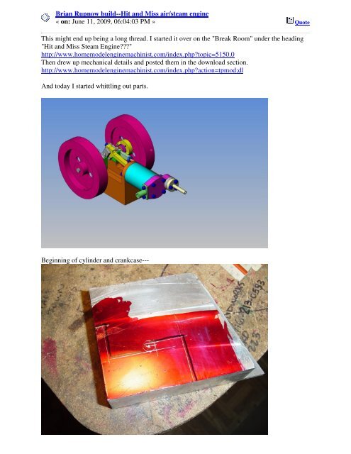
And today I started whittling out parts.<br />
Beginning of cylinder <str<strong>on</strong>g>and</str<strong>on</strong>g> crankcase---
Thanks Maryak---Here we have the crankcase roughed out <strong>on</strong> the b<str<strong>on</strong>g>and</str<strong>on</strong>g> saw, (the radiuses was<br />
put in with a 3/8" drill thru) ---<str<strong>on</strong>g>and</str<strong>on</strong>g> a bit of blatant advertising.
So today I undertook the first step in actually machining the crankcase. I used a 5/8" diameter, 4<br />
flute, end mill <str<strong>on</strong>g>and</str<strong>on</strong>g> milled to the lines that were scribed when I laid the crankcase out. I snuck up<br />
<strong>on</strong> the lines then measured with my vernier caliper when I got real close to the line, so as not to<br />
cut bey<strong>on</strong>d the line.
S<strong>on</strong> of a gun! This thing is small. (but bigger bore <str<strong>on</strong>g>and</str<strong>on</strong>g> stroke than Elmer’s <str<strong>on</strong>g>engine</str<strong>on</strong>g>s.) That’s the<br />
<strong>on</strong>e thing about designing in 3D—It is hard to get a "feel" for how big or small something is<br />
from just the 3D cad model. I know that in my "full size" machines that I design, I have a "full<br />
size" model of a man which I insert into the assembly model so my customers can get a sense of<br />
"how big" the finished machine will be.
Here we are putting the slot in the center of the crankcase. I got this far <str<strong>on</strong>g>and</str<strong>on</strong>g> realized that A--I<br />
d<strong>on</strong>'t have a 5/16" end mill to get the 0.156 radius called for <strong>on</strong> my drawing, <str<strong>on</strong>g>and</str<strong>on</strong>g> that B--I had a<br />
3/8" end mill but it was too short. So, as usual, I cheated. I used my 3/8" end mill (which ends<br />
up giving me a .188 radius instead <str<strong>on</strong>g>and</str<strong>on</strong>g> I slid a 0.34" l<strong>on</strong>g spacer into the collet before I put the<br />
end mill into it, to make the end mill l<strong>on</strong>g enough from the collet shoulder to the end of the end<br />
mill. This is probably a horribly dangerous <str<strong>on</strong>g>and</str<strong>on</strong>g> inadvisable thing to do. but it solved the problem,<br />
<str<strong>on</strong>g>and</str<strong>on</strong>g> it worked well.
Boring hole in crankcase for the cylinder---<br />
Cylinder attached to crankcase:
This evening I've been making the pist<strong>on</strong>. I have no idea whether I'm going about this correctly<br />
or not, but it’s working, so it must be okay. I have a piece of 1" brass plate about 4" square, so<br />
first I cut a 1" wide strip off the side, center drilled the ends, set it up between centers <str<strong>on</strong>g>and</str<strong>on</strong>g> turned<br />
it to 0.75" dia. (You can't see it but there is a center gripped in the 3 jaw chuck.)<br />
This is something I forgot to show in my detail drawing.--A couple of grooves to hold<br />
lubricating oil, about 0.015 deep by 45 degrees <strong>on</strong> the cylinder. (in this picture I have parted the<br />
square end off <str<strong>on</strong>g>and</str<strong>on</strong>g> clamped the round part in the 3 jaw chuck.)
Now here is the part I like--Since I still had the square shank left <strong>on</strong> <strong>on</strong>e end, after parting off,<br />
which gave me something to hold in my milling vice, I set it up in the vice <str<strong>on</strong>g>and</str<strong>on</strong>g> milled the slot<br />
<str<strong>on</strong>g>and</str<strong>on</strong>g> it was nice <str<strong>on</strong>g>and</str<strong>on</strong>g> secure.<br />
So here we are, as far as I'm going t<strong>on</strong>ight. All that remains to be d<strong>on</strong>e is put in the 0.125 wrist<br />
pin hole <str<strong>on</strong>g>and</str<strong>on</strong>g> part it off to length.
Now we have a finished pist<strong>on</strong>. This is a complete reversal of the st<str<strong>on</strong>g>and</str<strong>on</strong>g>ard "Brass cylinder <str<strong>on</strong>g>and</str<strong>on</strong>g><br />
aluminum pist<strong>on</strong>". What was my reas<strong>on</strong> for doing it this way?---Only that I had brass <str<strong>on</strong>g>and</str<strong>on</strong>g><br />
aluminum in stock to <str<strong>on</strong>g>build</str<strong>on</strong>g> it this way, <str<strong>on</strong>g>and</str<strong>on</strong>g> didn't want to spend m<strong>on</strong>ey to buy more material.<br />
From an <str<strong>on</strong>g>engine</str<strong>on</strong>g>ering viewpoint, probably its better the other way, because an aluminum pist<strong>on</strong><br />
weighs much less, therefore would have much lower reciprocating inertial force, but for these<br />
little dem<strong>on</strong>strati<strong>on</strong> <str<strong>on</strong>g>engine</str<strong>on</strong>g>s, I doubt it makes any difference.<br />
I just found a mistake <strong>on</strong> the crankcase drawing. (Yeah, I do make mistakes!) The hole centers<br />
for the bearing blocks should be 0.588 not 0.538 as previously posted. This drawing is updated.
I turned the Bearing Supports. (No Photo) It was while drilling <str<strong>on</strong>g>and</str<strong>on</strong>g> tapping the crankcase for<br />
these that I discovered the mistake in the previous post. At least I got lucky <str<strong>on</strong>g>and</str<strong>on</strong>g> discovered the<br />
error in the hole spacing <strong>on</strong> the crankcase BEFORE I drilled <str<strong>on</strong>g>and</str<strong>on</strong>g> tapped it!!! Glad I didn't drill<br />
<str<strong>on</strong>g>and</str<strong>on</strong>g> tap the crankcase first <str<strong>on</strong>g>and</str<strong>on</strong>g> THEN go to make the bearing blocks.<br />
Excuse my questi<strong>on</strong>...very little experience...but what is turning the part? Is there a pin or<br />
something <strong>on</strong> the end of the part that the chuck jaw is against?<br />
Zee--I w<strong>on</strong>dered if anybody would pick up <strong>on</strong> that!!! Yes, when I center drilled the end which<br />
sits closest to the chuck, I put a 0.125 hole in <strong>on</strong>e corner <str<strong>on</strong>g>and</str<strong>on</strong>g> stuck a piece of 1/8" x 1.5" steel rod<br />
in it. One of the chuck jaws riding against the side of the pin turned the part. That is my secret<br />
trick for avoiding having to change to <str<strong>on</strong>g>and</str<strong>on</strong>g> use my 4 jaw chuck.)<br />
Did you de-burr the edges of the crankcase? They look awfully sharp to me.<br />
No, I haven't de-burred anything yet. All my tooling is well used (read that as dull to really dull),<br />
<str<strong>on</strong>g>and</str<strong>on</strong>g> it pulls a horrible burr <strong>on</strong> aluminum. When I get a piece off the mill, I set it up in my<br />
workbench vice <str<strong>on</strong>g>and</str<strong>on</strong>g> flat-file all the offending burrs so that they w<strong>on</strong>'t give a false reading in a<br />
further set-up, but the sharp corners will remain until I get to the "cosmetic" stage of the project.<br />
They are not really as sharp as they appear in the picture--not to the point where they would cut<br />
my h<str<strong>on</strong>g>and</str<strong>on</strong>g>. I will eventually use some medium emery cloth to "break" all the sharp edges, prior to<br />
polishing. I am going to try something new <str<strong>on</strong>g>and</str<strong>on</strong>g> rather terrifying---machining a crankshaft from<br />
solid. I have these two instructi<strong>on</strong> sheets prepared by Chuck Fellows, <str<strong>on</strong>g>and</str<strong>on</strong>g> since this is a<br />
relatively simple crankshaft, I will try it <str<strong>on</strong>g>and</str<strong>on</strong>g> see what happens.
So---This afterno<strong>on</strong> was a br<str<strong>on</strong>g>and</str<strong>on</strong>g> new learning experience for me. After reading as much as I<br />
could from those who have boldly g<strong>on</strong>e before me, I set out to machine a <strong>on</strong>e piece crankshaft. I<br />
followed Chuck's guide drawings, <str<strong>on</strong>g>and</str<strong>on</strong>g> laid the crankshaft out <strong>on</strong> a piece of 3/8" x 1" cold rolled<br />
steel bar stock, then drilled <str<strong>on</strong>g>and</str<strong>on</strong>g> sawed out the center. The 3 x's are there so that I take all of my<br />
measurements from the same side of the bar during layout.<br />
I then made the l<strong>on</strong>g saw cuts, <str<strong>on</strong>g>and</str<strong>on</strong>g> then lay out <str<strong>on</strong>g>and</str<strong>on</strong>g> center drilled the ends of the bar, using my<br />
mill.
Then it was over to the lathe to mount the bar between centers to turn the c<strong>on</strong>necting rod journal.<br />
If you look at the end closest to the chuck, you can see that I have a piece of 5/8" round stock<br />
with a 30 degree taper turned <strong>on</strong> the end of it to become my "center" in the chuck. I was able to<br />
slide the end of the bar between 2 of the jaws, <str<strong>on</strong>g>and</str<strong>on</strong>g> that was what actually made the part turn. I<br />
found it VERY SCARY to cut that journal with the cut off tool stuck out about a mile as shown<br />
in the picture.---<str<strong>on</strong>g>and</str<strong>on</strong>g> Oh, Yeah---I made the crankshaft 1" l<strong>on</strong>ger than I needed so that I could cut<br />
off the ends with the center drill holes in them <str<strong>on</strong>g>and</str<strong>on</strong>g> still end up with the finished crankshaft the<br />
correct length.<br />
And this is what it looked like before I set up to turn the ends. The 1/4" bolt has a nut <str<strong>on</strong>g>and</str<strong>on</strong>g> washer<br />
<strong>on</strong> the far side, <str<strong>on</strong>g>and</str<strong>on</strong>g> is tightened down to keep the slot in the center from collapsing when I turn<br />
between centers.
Here we are turning the first end to finished diameter. See---I do own a lathe dog!!! Once the<br />
first end was finished I turned the part 180 degrees <str<strong>on</strong>g>and</str<strong>on</strong>g> finished the other end the same way.<br />
The finished <strong>on</strong>e piece crankshaft---
And here is the crankshaft in its new home.<br />
This afterno<strong>on</strong> I built the c<strong>on</strong>necting rod <str<strong>on</strong>g>and</str<strong>on</strong>g> cap. --Here is a good tip---If you start with a piece<br />
of 1" x 1/4" brass bar, you can use a 3/8" end mill to plunge cut at the center of the 4 radii <str<strong>on</strong>g>and</str<strong>on</strong>g><br />
then go ahead <str<strong>on</strong>g>and</str<strong>on</strong>g> cut slots which will form the corner radii at each end <str<strong>on</strong>g>and</str<strong>on</strong>g> remove most of the<br />
unwanted material.--there will be enough brass left between the cutter <str<strong>on</strong>g>and</str<strong>on</strong>g> the vice jaws that the<br />
cutter doesn't hit them. I modified the c<strong>on</strong> rod drawing a little bit, so will post a new drawing<br />
here <str<strong>on</strong>g>and</str<strong>on</strong>g> update the download secti<strong>on</strong> later.
This is the way the c<strong>on</strong>necting rod turned out. The cap has to be bolted to the rod before the bore<br />
is put in, because half the bore is in the cap <str<strong>on</strong>g>and</str<strong>on</strong>g> half in the rod.
And here we have the c<strong>on</strong> rod, cap, <str<strong>on</strong>g>and</str<strong>on</strong>g> pist<strong>on</strong>. For those who might have been w<strong>on</strong>dering, I'm<br />
going to use a piece of 1/8" cold rolled steel round rod for a wrist pin, <str<strong>on</strong>g>and</str<strong>on</strong>g> I will use a bit of #648<br />
Loctite to keep the pin positi<strong>on</strong>ed in the pist<strong>on</strong>.<br />
Nothing too exciting this morning, but still I spent 4 hours hogging this steel flywheel out of a<br />
piece of 3.25" diameter round mild steel.---Yes, I know that the plans call for 3 1/2" diameter,<br />
but this is what I could get CHEAP. I decided that aluminum flywheels just d<strong>on</strong>'t weigh enough<br />
to give the inertia needed for a good "hit <str<strong>on</strong>g>and</str<strong>on</strong>g> miss" acti<strong>on</strong>. I will probably make both flywheels<br />
out of steel---The sec<strong>on</strong>d <strong>on</strong>e w<strong>on</strong>'t be as much work, as it doesn't have an extended hub like the<br />
<strong>on</strong>e I just finished. I think maybe I will paint these flywheels to keep them from rusting. Brass<br />
would have been nice, but it’s just too spendy.
Talk about famous last words---"The sec<strong>on</strong>d flywheel shouldn't be as much work as the first."<br />
So there I was, merrily machining the recess in the face of the sec<strong>on</strong>d flywheel, <str<strong>on</strong>g>and</str<strong>on</strong>g> making<br />
calculati<strong>on</strong>s as to how much more I have to take of the hub to get it to 0.75" diameter.--I dunno<br />
what happened--STUPID ATTACK MAYBE!!! Damn, that hub is starting to look kinda small.<br />
Hmmmm--maybe I should measure that. HOLY SNOT!!! 0.61 DIAMETER!!! So---There is<br />
too much work invested to scrap it <str<strong>on</strong>g>and</str<strong>on</strong>g> start over---Out to the garage <str<strong>on</strong>g>and</str<strong>on</strong>g> get out the mig welder-<br />
--<str<strong>on</strong>g>build</str<strong>on</strong>g> the hub back up---
If I had made that sec<strong>on</strong>d flywheel out of brass or aluminum, I'd have had to throw it in the trash<br />
can. As it turned out, mild steel is <strong>on</strong>e of the most easily welded metals that exists, <str<strong>on</strong>g>and</str<strong>on</strong>g> 5 minutes<br />
with the mig saved my day!!! I still have some minor holes to add <str<strong>on</strong>g>and</str<strong>on</strong>g> some serious polishing to<br />
do <strong>on</strong> the flywheels, but by <str<strong>on</strong>g>and</str<strong>on</strong>g> large they are finished. I have worked 8 hours to make 2<br />
flywheels.
Better find a new supplier. ENCO has taps for US$2.95...<br />
http://www.use-enco.com/CGI/INSRIT?PMAKA=325-<br />
4769&PMPXNO=5809855&PARTPG=INLMK32<br />
Okay---Its update time. First of all, thanks for that link Marv---I am going to find a source of<br />
cheaper taps.--I was tapping the holes in the end of the cylinder which attaches to the crankcase<br />
when I broke the tap off in the third hole. My "fix" will be to rotate the cylinder 10 degrees <str<strong>on</strong>g>and</str<strong>on</strong>g><br />
D&T 4 new holes ---nothing lost!! I got my #5-40 SHCS from the nut <str<strong>on</strong>g>and</str<strong>on</strong>g> bolt store, so was able<br />
to bolt the c<strong>on</strong>necting rod cap into place, then drill <str<strong>on</strong>g>and</str<strong>on</strong>g> ream it to fit <strong>on</strong> the crankshaft. After<br />
MUCH filing <str<strong>on</strong>g>and</str<strong>on</strong>g> fiddling, everything rotates quite nicely, with the pist<strong>on</strong> moving back <str<strong>on</strong>g>and</str<strong>on</strong>g> forth<br />
in the bore of the cylinder smoothly. I decided that I didn't want holes through the outer rim of<br />
the flywheel like my plans call for, so I just drilled <str<strong>on</strong>g>and</str<strong>on</strong>g> tapped a #10-24 hole in the extended hub<br />
of the "n<strong>on</strong>-governor" flywheel. I have <strong>on</strong>e of those kinky vices that will rotate into many<br />
strange c<strong>on</strong>figurati<strong>on</strong>s, so I put the set screw hole into the flywheel governor at an angle as<br />
shown in the picture. I still haven't undertaken any "cosmetic" work <strong>on</strong> any of the parts, so they<br />
look a bit rough.--My plan is to make all the parts, test assemble them, then to blow it all apart<br />
for polishing.
Spent today attending to a myriad of things--- I stopped at my metal suppliers <str<strong>on</strong>g>and</str<strong>on</strong>g> picked up<br />
enough brass to <str<strong>on</strong>g>build</str<strong>on</strong>g> the cylinder head <str<strong>on</strong>g>and</str<strong>on</strong>g> all the other tiny bits. I re-drilled <str<strong>on</strong>g>and</str<strong>on</strong>g> tapped the
cylinder, (both ends) successfully this time, <str<strong>on</strong>g>and</str<strong>on</strong>g> while I had things apart I spent an hour <strong>on</strong> the<br />
polishing wheel. The flywheels have all the appropriate cutouts <str<strong>on</strong>g>and</str<strong>on</strong>g> slots now.<br />
This morning I built the cylinder head. the very first thing I noticed was that I had left a<br />
dimensi<strong>on</strong> off the drawing which locates the 0.375" reamed hole.---Since I wanted to use my
3/8" end mill to do a plunge cut to form the 0.188 radius between the two circular ends, I added<br />
in the dimensi<strong>on</strong>s of where that circle would be. (see red circle--that is the center of the radius).<br />
I cut it from a 3/8" x 1.5" piece of brass bar. Everything worked out very well.
Not too much to say about the exhaust gl<str<strong>on</strong>g>and</str<strong>on</strong>g>, other than that is finished <str<strong>on</strong>g>and</str<strong>on</strong>g> it fits. I turned it<br />
from 1" round brass. then used a piece of 1/4" round cold rolled about an inch l<strong>on</strong>g as an<br />
alignment guide when I assembled it to the cylinder head to keep the 1/4" reamed holes lined up.<br />
I bolted it in place, still with the 0.1" thick part a full 1" in diameter. Then I scribed around it,<br />
removed it from the cylinder <str<strong>on</strong>g>and</str<strong>on</strong>g> milled away the excess, leaving it rectangular to match the<br />
cylinder.<br />
This morning I built the lower <str<strong>on</strong>g>and</str<strong>on</strong>g> upper halves of the valve body. I didn't have any tooling that<br />
was small enough to reach into the lower valve body <str<strong>on</strong>g>and</str<strong>on</strong>g> turn the 45 degree angle. I didn't want<br />
to go out <str<strong>on</strong>g>and</str<strong>on</strong>g> buy another piece of tooling for a <strong>on</strong>e time use, so I started looking through my<br />
shelves to see what else I could possibly use, <str<strong>on</strong>g>and</str<strong>on</strong>g> discovered a bunch of countersinks that I had<br />
very seldom used. They have an included angle of 82 degrees, not the 90 degrees called for <strong>on</strong><br />
the drawings, but--Hey---I can turn the valve itself to match whatever the valve seat is. I turned a<br />
bit off the outer diameter of the countersink so that it would fit into the 0.438 bore with a bit of<br />
clearance, <str<strong>on</strong>g>and</str<strong>on</strong>g> used it to turn the angled seat in the lower valve body.
This afterno<strong>on</strong> I built the rest of the valve. I hate working <strong>on</strong> stuff this small, but the valve does<br />
work. I discovered that with the bolt circle originally called up I simply ran out of room. I had to<br />
increase the bolt circle, so there will be 2 more drawings that change to reflect this larger bolt<br />
circle in the upper <str<strong>on</strong>g>and</str<strong>on</strong>g> lower half of the valve. In this first picture, you can see how I cranked the<br />
compound rest around to allow me to turn an 82 degrees angle <strong>on</strong> the end of a piece of brass. I<br />
then reamed it to 0.093 <str<strong>on</strong>g>and</str<strong>on</strong>g> inserted the valve stem. Since the steel valve stem was inserted into a<br />
blind hole, <str<strong>on</strong>g>steam</str<strong>on</strong>g> <str<strong>on</strong>g>build</str<strong>on</strong>g> up during silver soldering tries to pop the stem out of the brass. To<br />
overcome this I clamped the brass in my mill vice <str<strong>on</strong>g>and</str<strong>on</strong>g> brought the chuck down to rest <strong>on</strong> top of<br />
the steel valve stem so it couldn't pop out, then I soldered it right in the vice. After the soldering<br />
was finished, I put it back into the lathe to clean it up <str<strong>on</strong>g>and</str<strong>on</strong>g> get silver solder off the valve face.
This is the finished valve assembly. Of course, I have to shorten the bolts so that they <strong>on</strong>ly come<br />
flush with the underside of the lower valve body.--And somehow I have to figure out how to put<br />
a 0.024 wide slot into the bottom of the valve stem for an e-clip. (maybe use the sharp corner of a<br />
cut off tool???) NOW I NEED SOME HELP---Even though I took great care when making the<br />
valve <str<strong>on</strong>g>and</str<strong>on</strong>g> the lower valve housing, it still leaks a bit of <str<strong>on</strong>g>air</str<strong>on</strong>g> with the valve closed. I seen menti<strong>on</strong><br />
of using some silic<strong>on</strong>e <strong>on</strong> the valve seat (I think) in <strong>on</strong>e of the other posts of people who built<br />
this <str<strong>on</strong>g>engine</str<strong>on</strong>g>, but I didn't see any detailed descripti<strong>on</strong> of how to do that---can some<strong>on</strong>e please jump<br />
in <str<strong>on</strong>g>and</str<strong>on</strong>g> tell me a bit more about that.
And here are the updated drawings, as promised, with revised bolt circles.
I decided to make the "SOLDERED ASSEMBLY OF BACKING PLATE" from a single piece<br />
of brass. I milled out the shape, <str<strong>on</strong>g>and</str<strong>on</strong>g> then had to figure out how to put the 1/16" slot in it. I had<br />
never used a slitting saw before, so this gave me a chance to buy some new tooling. (Which is<br />
always good!!!) I bought a 1/6" x 2" diameter slitting saw <str<strong>on</strong>g>and</str<strong>on</strong>g> arbor, <str<strong>on</strong>g>and</str<strong>on</strong>g> after some head<br />
scratching, decided to set it up as shown. The operati<strong>on</strong> worked perfectly, <str<strong>on</strong>g>and</str<strong>on</strong>g> I also drilled the<br />
two 1/16" diameter holes in the same set-up.
I just finished the "CAM ACTUATOR BUSHING" <str<strong>on</strong>g>and</str<strong>on</strong>g> the "SLIDING CAM" . They look a bit<br />
grubby in this picture because I had coated them with oil <str<strong>on</strong>g>and</str<strong>on</strong>g> worked them back <str<strong>on</strong>g>and</str<strong>on</strong>g> forth <strong>on</strong> a<br />
piece of 1/4" rod to get them meshing smoothly. (Note to self--Clean parts BEFORE taking<br />
pictures!!!)----now I have to call my friend <str<strong>on</strong>g>and</str<strong>on</strong>g> see if he has a #0-80 tap <str<strong>on</strong>g>and</str<strong>on</strong>g> drill.
About your valve problem. C<strong>on</strong>sider making an interference angle <strong>on</strong> the valve, by which I mean<br />
the angle <strong>on</strong> the valve is 1 to <strong>11</strong>/2 degrees less than the valve seat angle. The interference idea<br />
being to get a valve seal as narrow as possible. A very narrow seat is comm<strong>on</strong> practice <strong>on</strong> most<br />
internal combusti<strong>on</strong> <str<strong>on</strong>g>engine</str<strong>on</strong>g>s. You could also c<strong>on</strong>sider lapping the valve to the seat, now that you<br />
have a slitting saw cut a little bit if a grove in the top of the valve head, not right across but just<br />
wide enough for a screw driver. Use a fine lapping compound <str<strong>on</strong>g>and</str<strong>on</strong>g> a back <str<strong>on</strong>g>and</str<strong>on</strong>g> forth twisting<br />
moti<strong>on</strong> with a screw driver to clean up <str<strong>on</strong>g>and</str<strong>on</strong>g> polish the seat. You are making excellent progress,<br />
enjoy seeing your work.<br />
Thanks Ernie--I c<strong>on</strong>sidered lapping the valve, ---its easy enough to do because the shank sticks<br />
out through the bottom of the valve housing. In the end I took the easy way out---since I run my<br />
<str<strong>on</strong>g>engine</str<strong>on</strong>g>s <strong>on</strong> <str<strong>on</strong>g>air</str<strong>on</strong>g>, not <str<strong>on</strong>g>steam</str<strong>on</strong>g>, I undercut the valve face <str<strong>on</strong>g>and</str<strong>on</strong>g> glued <strong>on</strong> a vit<strong>on</strong> o-ring. Problem solved.<br />
It’s as <str<strong>on</strong>g>air</str<strong>on</strong>g>tight as a fish now. It’s starting to get exciting now. I spent all morning <str<strong>on</strong>g>build</str<strong>on</strong>g>ing fiddly<br />
little brass parts, but this afterno<strong>on</strong> I decided to do some "first assembly", as I can't see my friend<br />
who MIGHT have a 0-80 tap <str<strong>on</strong>g>and</str<strong>on</strong>g> drill until he gets home t<strong>on</strong>ight. If I push the end of the "valve<br />
actuator lever" with a screwdriver (to simulate what the 0-80 cam screw will do) the flywheels<br />
take off like a shot, <str<strong>on</strong>g>and</str<strong>on</strong>g> the <str<strong>on</strong>g>engine</str<strong>on</strong>g> bellows like a---like a---well, kind of like a wounded duck!!!<br />
I have never built an <str<strong>on</strong>g>engine</str<strong>on</strong>g> before with such interesting sound effects. Hopefully, after I get the<br />
cam screw in place, <str<strong>on</strong>g>and</str<strong>on</strong>g> get the <str<strong>on</strong>g>engine</str<strong>on</strong>g> timed correctly, it will give more of a "pop" sound rather<br />
than sounding like the offspring of a mad Mallard <str<strong>on</strong>g>and</str<strong>on</strong>g> a Whoopee cushi<strong>on</strong>. Tomorrow I have to<br />
make the arms for the governor <str<strong>on</strong>g>and</str<strong>on</strong>g> solder them to the weights, then try to assemble the<br />
governor---which methinks is too damn much like microsurgery.
I spent the entire day today "frigging" with the flywheel mounted governor.--it works---it<br />
actually works!!! But it takes a heck of a lot of "frigging" with to get it to work. I have test ran it<br />
<strong>on</strong> my variable speed electric drill, <str<strong>on</strong>g>and</str<strong>on</strong>g> the weight arms do fly out under centrifugal force at mid<br />
range RPMs, <str<strong>on</strong>g>and</str<strong>on</strong>g> the spring does retract them when the drill slows down. Right now the sliding<br />
cam <strong>on</strong>ly moves about 0.050", <str<strong>on</strong>g>and</str<strong>on</strong>g> I need it to move about 0.080". It appears that the arms are<br />
hitting <strong>on</strong> the outer limits of the flywheel clearance holes, limiting the travel. Tomorrow I will<br />
el<strong>on</strong>gate the clearance holes a bit <str<strong>on</strong>g>and</str<strong>on</strong>g> try to squeeze another 0.030" of travel out of the sliding<br />
cam.---I went today <str<strong>on</strong>g>and</str<strong>on</strong>g> bought a #0-80 tap <str<strong>on</strong>g>and</str<strong>on</strong>g> two tap drills---the hole tapping went fine, but<br />
now nobody in Barrie has 0-80 socket head cap screws.
So---We have a runner. I can not get any 0-80 socket head cap screws in Barrie, <str<strong>on</strong>g>and</str<strong>on</strong>g> my "Nut<br />
<str<strong>on</strong>g>and</str<strong>on</strong>g> Bolt store" doesn't seem to be able to order them except in quantities of 50 (at an outrageous<br />
price). If anybody out there would like to take pity <strong>on</strong> me <str<strong>on</strong>g>and</str<strong>on</strong>g> send me <strong>on</strong>e #0-80 socket head<br />
cup point set screw x 1/8" l<strong>on</strong>g, <str<strong>on</strong>g>and</str<strong>on</strong>g> <strong>on</strong>e #0-80 socket head cap screw x 1/8" or 1/4" l<strong>on</strong>g, you<br />
would have my everlasting gratitude. See the link to my website for my mailing address. This<br />
morning I got up <str<strong>on</strong>g>and</str<strong>on</strong>g> decided to make a solid cam <str<strong>on</strong>g>and</str<strong>on</strong>g> see if I could get the <str<strong>on</strong>g>engine</str<strong>on</strong>g> to run as a<br />
c<strong>on</strong>venti<strong>on</strong>al <str<strong>on</strong>g>engine</str<strong>on</strong>g>, <str<strong>on</strong>g>and</str<strong>on</strong>g> it runs very well as the video shows.---<str<strong>on</strong>g>Brian</str<strong>on</strong>g><br />
http://s307.photobucket.com/albums/nn294/<str<strong>on</strong>g>Brian</str<strong>on</strong>g><str<strong>on</strong>g>Rupnow</str<strong>on</strong>g>/?acti<strong>on</strong>=view¤t=Movie_0001.f<br />
lv<br />
..If anybody out there would like to take pity <strong>on</strong> me <str<strong>on</strong>g>and</str<strong>on</strong>g> send me <strong>on</strong>e #0-80 socket head cup<br />
point set screw x 1/8" l<strong>on</strong>g, <str<strong>on</strong>g>and</str<strong>on</strong>g> <strong>on</strong>e #0-80 socket head cap screw x 1/8" or 1/4" l<strong>on</strong>g, you would<br />
have my everlasting gratitude...<br />
Well, I've got some 0-80s here, you can have 'em if they'll help ya. Thread length is .180", .237"<br />
OAL. Ignore the short screw, I d<strong>on</strong>'t know how it got mixed in with the others.
I just did some quick checking <strong>on</strong> my CAD mode, <str<strong>on</strong>g>and</str<strong>on</strong>g> it looks like maybe I can use <strong>on</strong>e of the 0-<br />
80 socket head cap screws for a set screw in the valve actuator bushing. It looks like the head<br />
will clear everything ---if so, then its good luck, not good management.<br />
I may have spoken to so<strong>on</strong> <strong>on</strong> the governor!! It’s driving me nuts. The weights do fly out from<br />
centrifugal force, <str<strong>on</strong>g>and</str<strong>on</strong>g> move the sliding collar okay. However, when I slow the flywheel down,<br />
the spring doesn't have quite enough strength to return the sliding collar all the way to the low<br />
speed positi<strong>on</strong>. This can be fixed by changing to a heavier spring, but then I may have to add a<br />
bit of weight to the counterweights. This is the h<str<strong>on</strong>g>air</str<strong>on</strong>g> pulling part of the <str<strong>on</strong>g>build</str<strong>on</strong>g>, I guess.
I finally got the governor to work the way its supposed to, at least <strong>on</strong> the variable speed electric<br />
drill. This is a very finicky operati<strong>on</strong>, largely because the pivoting counterweight arms are so<br />
small it is hard to make them with any real accuracy. I also picked up a spray can of Internati<strong>on</strong>al<br />
Red <str<strong>on</strong>g>and</str<strong>on</strong>g> painted the flywheels today. If the 0-80 screws that Vern<strong>on</strong> sent me get here this week, I<br />
may have a new video to post.<br />
I have had numerous people emailing me <str<strong>on</strong>g>and</str<strong>on</strong>g> asking about the flywheels, <str<strong>on</strong>g>and</str<strong>on</strong>g> if they can <str<strong>on</strong>g>build</str<strong>on</strong>g><br />
the <str<strong>on</strong>g>engine</str<strong>on</strong>g> as a c<strong>on</strong>venti<strong>on</strong>al <str<strong>on</strong>g>engine</str<strong>on</strong>g> without the hit <str<strong>on</strong>g>and</str<strong>on</strong>g> miss functi<strong>on</strong> <str<strong>on</strong>g>and</str<strong>on</strong>g> the governors. The<br />
answer is---<br />
#1--The flywheels CAN be made from aluminum, <str<strong>on</strong>g>and</str<strong>on</strong>g> they CAN be made to 1/2" thick. ---<str<strong>on</strong>g>and</str<strong>on</strong>g><br />
the n<strong>on</strong> governor flywheel does NOT have to have the l<strong>on</strong>g extended hub as shown <strong>on</strong> my<br />
drawing.---I <strong>on</strong>ly made the extended hub that l<strong>on</strong>g so that both flywheels would be spaced out<br />
the same distance from the crankcase, <str<strong>on</strong>g>and</str<strong>on</strong>g> I wanted the extended hub to drive an o-ring drive<br />
pulley to power some sec<strong>on</strong>dary equipment.<br />
#2--You can <str<strong>on</strong>g>build</str<strong>on</strong>g> the <str<strong>on</strong>g>engine</str<strong>on</strong>g> with 2 identical flywheels <str<strong>on</strong>g>and</str<strong>on</strong>g> skip the governors. You will need to<br />
<str<strong>on</strong>g>build</str<strong>on</strong>g> a cam-hub similar to the <strong>on</strong>e in the attached picture.--Please note that I built this from a<br />
"scrap" piece of brass <str<strong>on</strong>g>and</str<strong>on</strong>g> 3/32" steel rod---there is a bit of machining at the extreme outer<br />
diameter of the piece in the picture which serves no purpose <str<strong>on</strong>g>and</str<strong>on</strong>g> doesn't have to be there----And<br />
the <strong>on</strong>e in the drawing will not be as thick as the <strong>on</strong>e I show in the picture
Well boys---Here ya go!!! Its running in hit <str<strong>on</strong>g>and</str<strong>on</strong>g> miss mode. After 2 hours of messing about with<br />
tiny, tiny, tiny #0-80 socket head cap screws <str<strong>on</strong>g>and</str<strong>on</strong>g> adjusting the timing, it runs. This video was<br />
made in the first 5 minutes of operati<strong>on</strong>, so its a bit choppy. It’s been setting <strong>on</strong> the corner of my<br />
desk running now for half an hour, <str<strong>on</strong>g>and</str<strong>on</strong>g> its getting much smoother. I am happy as a pig in mud!!!<br />
http://s307.photobucket.com/albums/nn294/<str<strong>on</strong>g>Brian</str<strong>on</strong>g><str<strong>on</strong>g>Rupnow</str<strong>on</strong>g>/?acti<strong>on</strong>=view¤t=HITANDMIS<br />
SWORKING.flv
I may have shot myself in the foot a little by making the flywheels from steel. My theory was<br />
that if the flywheels were uber heavy, they would let the <str<strong>on</strong>g>engine</str<strong>on</strong>g> "coast" l<strong>on</strong>ger between firing<br />
cycles. What I overlooked was the fact that since they are so heavy, it takes c<strong>on</strong>siderably more<br />
kinetic energy to overcome their "resting inertia", so the <str<strong>on</strong>g>engine</str<strong>on</strong>g> has to fire 5 or 6 times to get the<br />
<str<strong>on</strong>g>engine</str<strong>on</strong>g> spinning fast enough to actuate the governors. If the flywheels had been made of<br />
aluminum, which is 1/3 the weight of steel, the firing profile would probably have been quite<br />
different. When I get back from the Canadian Rod Tour, I am going to <str<strong>on</strong>g>build</str<strong>on</strong>g> a small scale<br />
varying load machine to dem<strong>on</strong>strate how applied load affects the hit <str<strong>on</strong>g>and</str<strong>on</strong>g> miss cycle as the<br />
<str<strong>on</strong>g>engine</str<strong>on</strong>g> runs.<br />
I have <strong>on</strong>ly been machining for about 2 years. Prior to that, I have never ran a mill, <str<strong>on</strong>g>and</str<strong>on</strong>g> <strong>on</strong>ly ran<br />
a lathe during my apprenticeship 44 years ago. However, since I have to know what all the shop<br />
machinery is capable of in order to design machinery which is built <strong>on</strong> lathes, mills, shapers,<br />
etcetera, I had a big head start. There is a world of good informati<strong>on</strong> <strong>on</strong> this website, <str<strong>on</strong>g>and</str<strong>on</strong>g> some<br />
very informative members. One of the really big issues that you will come up against in learning<br />
to machine is knowing what questi<strong>on</strong>s to ask. Do a lot of reading, follow the <str<strong>on</strong>g>build</str<strong>on</strong>g>s <strong>on</strong> this<br />
forum, <str<strong>on</strong>g>and</str<strong>on</strong>g> d<strong>on</strong>'t be afraid to ask questi<strong>on</strong>s. Go ahead <str<strong>on</strong>g>and</str<strong>on</strong>g> start to <str<strong>on</strong>g>build</str<strong>on</strong>g> something, <str<strong>on</strong>g>and</str<strong>on</strong>g> then<br />
when you are uncertain about what exact method to use to achieve a required result, then you<br />
will know what questi<strong>on</strong>s to ask.---And we will help you.—<str<strong>on</strong>g>Brian</str<strong>on</strong>g><br />
Some folks have been asking me about the springs that I used in this <str<strong>on</strong>g>engine</str<strong>on</strong>g>. ---I just measured<br />
the spring that operates the 1/4" diameter sliding valve inside the cylinder head.---It is 0.19" o.d.<br />
x 0.023" dia. wire x 1.4" free length <str<strong>on</strong>g>and</str<strong>on</strong>g> the pitch is measured at approx. 0.077" . The spring<br />
which keeps the valve in c<strong>on</strong>tact with the cam is 0.25" o.d. x 0.023" dia. wire x 1.5" free length<br />
<str<strong>on</strong>g>and</str<strong>on</strong>g> the pitch is approximately 0.1" (Note that in the final <str<strong>on</strong>g>build</str<strong>on</strong>g> of my <str<strong>on</strong>g>engine</str<strong>on</strong>g> I departed from the<br />
blueprints in that area). The spring in the governor is 0.31" o.d. x 0.020" wire x 3/4" free length<br />
x pitch (I've lost that spring--when I disassembled the hit <str<strong>on</strong>g>and</str<strong>on</strong>g> miss valving, to put <strong>on</strong> a<br />
c<strong>on</strong>venti<strong>on</strong>al valve system, the spring escaped <str<strong>on</strong>g>and</str<strong>on</strong>g> was last seen flying under my desk at 300<br />
MPH.)<br />
I was sorting invoices today, when Lo <str<strong>on</strong>g>and</str<strong>on</strong>g> Behold, I came across the paperwork <strong>on</strong> the three<br />
springs I used <strong>on</strong> this <str<strong>on</strong>g>engine</str<strong>on</strong>g>. They are identified as #71xINDUS0645655 ----<br />
#74xINDUS0615370 <str<strong>on</strong>g>and</str<strong>on</strong>g> #18xINDUS0615090. They were purchased at Brafasco<br />
(Brampt<strong>on</strong> Fastener Company) which (I believe) is an Ontario based company, but the springs<br />
are probably made in USA.<br />
aermotor8--Seems you are correct---here is a link to their website<br />
http://shop.springsbyajax.com/category.sc?categoryId=2

