Structure/Property Relationships in Irons and ... - ASM International
Structure/Property Relationships in Irons and ... - ASM International
Structure/Property Relationships in Irons and ... - ASM International

Create successful ePaper yourself
Turn your PDF publications into a flip-book with our unique Google optimized e-Paper software.
Metals H<strong>and</strong>book Desk Edition, Second Edition<br />
J.R. Davis, Editor, p 153-173<br />
<strong>Structure</strong>/<strong>Property</strong><br />
<strong>Relationships</strong> <strong>in</strong> <strong>Irons</strong> <strong>and</strong> Steels<br />
THE PROPERTIES of irons <strong>and</strong> steels are<br />
l<strong>in</strong>ked to the chemical composition, process<strong>in</strong>g<br />
path, <strong>and</strong> result<strong>in</strong>g microstructure of the material;<br />
this correspondence has been known s<strong>in</strong>ce the<br />
early part of the twentieth century. For a particular<br />
iron <strong>and</strong> steel composition, most properties depend<br />
on microstructure. These properties are called<br />
Bruce L. Bramfitt, Homer Research Laboratories, Bethlehem Steel Corporation<br />
Basis of Material Selection ............................................... 153<br />
Role of Microstructure .................................................. 155<br />
Ferrite ............................................................. 156<br />
Pearlite ............................................................ 158<br />
Ferrite-Pearl ite ....................................................... 160<br />
Ba<strong>in</strong>ite ............................................................ 162<br />
Martensite .................................... ...................... 164<br />
Austenite ........................................................... 169<br />
Ferrite-Cementite ..................................................... 170<br />
Ferrite-Martensite .................................................... 171<br />
Ferrite-Austenite ..................................................... 171<br />
Graphite ........................................................... 172<br />
Cementite .......................................................... 172<br />
This Section was adapted from Materials 5election <strong>and</strong> Design, Volume 20, <strong>ASM</strong> H<strong>and</strong>book, 1997,<br />
pages 357-382. Additional <strong>in</strong>formation can also be found <strong>in</strong> the Sections on cast irons <strong>and</strong> steels which<br />
immediately follow <strong>in</strong> this H<strong>and</strong>book <strong>and</strong> by consult<strong>in</strong>g the <strong>in</strong>dex.<br />
structure-sensitive properties, for example, yield<br />
strength <strong>and</strong> hardness. The structure-<strong>in</strong>sensitive<br />
properties, for example, electrical conductivity,<br />
are not discussed <strong>in</strong> this Section. Process<strong>in</strong>g is a<br />
means to develop <strong>and</strong> control microstructure, for<br />
example, hot roll<strong>in</strong>g, quench<strong>in</strong>g, <strong>and</strong> so forth. In<br />
this Section, the role of these factors is described<br />
Copyright © 1998 <strong>ASM</strong> <strong>International</strong>®<br />
All rights reserved.<br />
www.asm<strong>in</strong>ternational.org<br />
<strong>in</strong> both theoretical <strong>and</strong> practical terms, with par-<br />
ticular focus on the role of microstructure.<br />
Basis of Material Selection<br />
In order to select a material for a particular<br />
component, the designer must have an <strong>in</strong>timate<br />
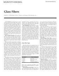
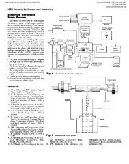
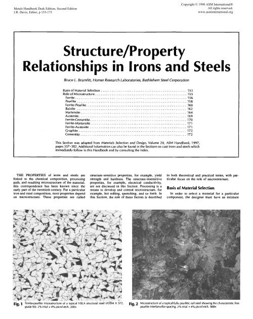
" "o" - grade 50). 2% nital + 4% picral etch. 200x Fig. :2 Microstructu<br />
repearlite <strong>in</strong>terlamellar°f a typicalspac<strong>in</strong>g.fUllY2%pearlitiCnital + 4%rail steelpicralShow<strong>in</strong>getch. 500xthe characteristic f<strong>in</strong>e
154/<strong>Structure</strong>/<strong>Property</strong> <strong>Relationships</strong> <strong>in</strong> <strong>Irons</strong> <strong>and</strong> Steels<br />
knowledge of what properties are required. Con-<br />
sideration must be given to the environment<br />
(corrosive, high temperature, etc.) <strong>and</strong> how the<br />
component will be fabricated (welded, bolted,<br />
etc.). Once these property requirements are es-<br />
tablished the material selection process can be-<br />
g<strong>in</strong>. Some of the properties to be considered<br />
are:<br />
Mechanical properties Other properties/<br />
Strength characteristics<br />
Tensile strength (ultimate Formability<br />
strength) Dmwability<br />
Yield strength Stretchability<br />
Compressive strength Bendability<br />
Hardness Wear resistance<br />
Toughness Abrasion resistance<br />
Notch toughness Gall<strong>in</strong>g resistance<br />
Fracture toughness Slid<strong>in</strong>g wear resistance<br />
Ductility Adhesive wear resistance<br />
Total elongation Mach<strong>in</strong>ability<br />
Reduction <strong>in</strong> area Weldability<br />
Fatigue resistance<br />
Table 1 lists mechanical properties of selected steels<br />
<strong>in</strong> various heat-treated or cold-worked conditions.<br />
In the selection process, what is required for<br />
one application may be totally <strong>in</strong>appropriate for<br />
another application. For example, steel beams for<br />
a railway bridge require a totally different set of<br />
properties than the steel rails that are attached to<br />
the wooden ties on the bridge deck. In design<strong>in</strong>g<br />
the bridge, the steel must have sufficient strength<br />
to withst<strong>and</strong> substantial applied loads. In fact,<br />
the designer will generally select a steel with<br />
higher strength than actually required. Also, the<br />
designer knows that the steel must have fracture<br />
toughness to resist the growth <strong>and</strong> propagation of<br />
cracks <strong>and</strong> must be capable of be<strong>in</strong>g welded so<br />
that structural members can be jo<strong>in</strong>ed without<br />
sacrific<strong>in</strong>g strength <strong>and</strong> toughness. The steel<br />
bridge must also be corrosion resistant. This can<br />
be provided by a protective layer of pa<strong>in</strong>t. If<br />
pa<strong>in</strong>t<strong>in</strong>g is not allowed, small amounts of certa<strong>in</strong><br />
alloy<strong>in</strong>g elements such as copper <strong>and</strong> chromium<br />
can be added to the steel to <strong>in</strong>hibit or reduce<br />
corrosion rates. Thus, the steel selected for the<br />
bridge would be a high-strength low-alloy<br />
(HSLA) structural steel such as ASTM A572,<br />
grade 50 or possibly a weather<strong>in</strong>g steel such as<br />
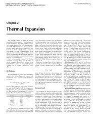
ASTM A588. A t);pical HSLA steel has a ferrite-<br />
pearlite microstructure as seen <strong>in</strong> Fig. 1 <strong>and</strong> is<br />
microalloyed with vanadium <strong>and</strong>/or niobium for<br />
strengthen<strong>in</strong>g. (Microalloy<strong>in</strong>g is a term used to<br />
describe the process of us<strong>in</strong>g small additions of<br />
carbonitride form<strong>in</strong>g elements--titanium, vana-<br />
dium, <strong>and</strong> niobium--to strengthen steels by gra<strong>in</strong><br />
ref<strong>in</strong>ement <strong>and</strong> precipitation harden<strong>in</strong>g.)<br />
On the other h<strong>and</strong>, the steel rails must have<br />
high strength coupled with excellent wear resis-<br />
tance. Modem rail steels consist of a fully pearli-<br />
tic microstructure with a f<strong>in</strong>e pearlite <strong>in</strong>terlamel-<br />
lar spac<strong>in</strong>g, as shown <strong>in</strong> Fig. 2. Pearlite is unique<br />
because it is a lamellar composite consist<strong>in</strong>g of<br />
88% soft, ductile ferrite <strong>and</strong> 12% hard, brittle<br />
cementite (Fe3C). The hard cementite plates pro-<br />
vide excellent wear resistance, especially when<br />
embedded <strong>in</strong> soft ferrite. Pearlitic steels have<br />
high strength <strong>and</strong> are fully adequate to support<br />
heavy axle loads of modem locomotives <strong>and</strong><br />
freight cars. Most of the load is applied <strong>in</strong> com-<br />
pression. Pearlitic steels also have relatively<br />
poor toughness <strong>and</strong> cannot generally withst<strong>and</strong><br />
impact loads without failure. The rail steel could<br />
not meet the requirements of the bridge builder,<br />
Table I Mechanical properties of selected steels<br />
Tensile Yield<br />
strength strength<br />
Steel Condition MPa ksi MPa kd<br />
Elongation<br />
iaS0muma, Reduction Hardness,<br />
Carbon steel bar(a)<br />
1006 Hot rolled 295 43 165 24 30 55 86<br />
Colddrawn 330 48 285 41 20 45 95<br />
1008 Hot rolled 305 44 170 24.5 30 55 86<br />
Colddrawn 340 49 285 41.5 20 45 95<br />
1010 Hot rolled 325 47 180 26 28 50 95<br />
Cold drawn 365 53 305 44 20 40 105<br />
1012 Hot rolled 330 48 185 26.5 28 50 95<br />
Colddrawn 370 54 310 45 19 40 105<br />
1015 Hot rolled 345 50 190 27.5 28 50 101<br />
Cold drawn 385 56 325 47 18 40 111<br />
1016 Hot rolled 380 55 205 30 25 50 110<br />
Cold dmwn 420 61 350 51 18 40 121<br />
1017 Hot rolled 365 53 200 29 26 50 105<br />
Cold drawn 405 59 340 49 18 40 116<br />
1018 Hot rolled 400 58 220 32 25 50 116<br />
Cold drawn 440 64 370 54 15 40 126<br />
1019 Hot rolled 405 59 225 32.5 25 50 116<br />
Cold drawn 455 66 380 55 15 40 131<br />
1020 Hot rolled 380 55 205 30 25 50 l 1 l<br />
Cold drawn 420 61 350 51 15 40 121<br />
1021 Hot rolled 420 61 230 33 24 48 116<br />
Colddrawn 470 68 395 57 15 40 131<br />
1022 Hot rolled 425 62 235 34 23 47 121<br />
Colddrawn 475 69 400 58 15 40 137<br />
1023 Hot rolled 385 56 215 31 25 50 111<br />
Cold drawn 425 62 360 52.5 15 40 121<br />
1524 Hot rolled 510 74 285 41 20 42 149<br />
Cold drawn 565 82 475 69 12 35 163<br />
1025 Hot rolled 400 58 220 32 25 50 116<br />
Colddrawn 440 64 370 54 15 40 126<br />
1026 Hot rolled 440 64 240 35 24 49 126<br />
Colddrawn 490 71 415 60 15 40 143<br />
1527 Hot rolled 515 75 285 41 18 40 149<br />
Colddmwn 570 83 485 70 12 35 163<br />
1030 Hot rolled 470 68 260 37.5 20 42 137<br />
Cold drawn 525 76 440 64 12 35 149<br />
1035 Hot rolled 495 72 270 39.5 18 40 143<br />
Colddrawn 550 80 460 67 12 35 163<br />
1536 Hot rolled 570 83 315 45.5 16 40 163<br />
COld drawn 635 92 535 77.5 12 35 187<br />
1037 Hot rolled 510 74 280 40.5 18 40 143<br />
Cold drawn 565 82 475 69 12 35 167<br />
1038 Hot rolled 515 75 285 41 18 40 149<br />
Colddrawn 570 83 485 70 12 35 163<br />
1039 Hot rolled 545 79 300 43.5 16 40 156<br />
Cold drawn 605 88 510 74 12 35 179<br />
1040 Hot rolled 525 76 290 42 18 40 149<br />
Colddrawn 585 85 490 71 12 35 170<br />
1541 Hot rolled 635 92 350 51 15 40 187<br />
Cold drawn 705 102.5 600 87 10 30 207<br />
Annealed, cold drawn 650 94 550 80 10 45 184<br />
1042 Hot rolled 550 80 305 44 16 40 163<br />
Colddrawn 6!5 89 515 75 12 35 179<br />
Normalized, cold drawn 585 85 505 73 12 45 179<br />
1043 Hot rolled 565 82 310 45 16 40 163<br />
Cold drawn 625 91 530 77 12 35 179<br />
Normalized, cold drown 600 87 515 75 12 45 179<br />
1044 Hot rolled 550 80 305 44 16 40 163<br />
1045 Hot rolled 565 82 310 45 16 40 163<br />
Colddmwn 625 91 530 77 12 35 179<br />
Annealed, cold drawn 585 85 505 73 12 45 170<br />
1046 Hot rolled 585 85 325 47 15 40 170<br />
Cold drawn 650 94 545 79 12 35 187<br />
Annealed, cold drawn 620 90 515 75 12 45 179<br />
1547 Hot rolled 650 94 360 52 15 30 192<br />
Cold drawn 710 103 605 88 10 28 207<br />
Annealed, cold drawn 655 95 585 85 10 35 187<br />
1548 Hot rolled 660 96 365 53 14 33 197<br />
Colddrawn 735 106.5 615 89.5 10 28 217<br />
Annealed, cold drawn 645 93.5 540 78.5 10 35 192<br />
(cont<strong>in</strong>ued)<br />
(a) All values are estimated m<strong>in</strong>imum values; type 1100 series steels are rated on the basis of 0.10% max Si or coarse-gra<strong>in</strong> melt-<br />
<strong>in</strong>g practice; the mechanical properties shown are expected m<strong>in</strong>imums for the sizes rang<strong>in</strong>g from 19 to 31.8 mm (0.75 to 1.25<br />
<strong>in</strong>.). (b) Most data are for 25 mm (1 <strong>in</strong>.) diam bar. Source: Ref 1
Table I (cont<strong>in</strong>ued)<br />
Tensile Yield<br />
strength strength<br />
Steel Condition MPa ksi MPa ksi<br />
<strong>Structure</strong>/<strong>Property</strong> <strong>Relationships</strong> <strong>in</strong> <strong>Irons</strong> <strong>and</strong> Steels / 155<br />
Elongation<br />
<strong>in</strong> 50 ram, Reduction Hardness,<br />
% ~a area, % HB<br />
Carbon steel bar(a) (cont<strong>in</strong>ued)<br />
1049 Hot rolled 600 87 330 48 15 35 179<br />
Cold drawn 670 97 560 81.5 10 30 197<br />
Annealed, cold drawn 635 92 530 77 10 40 187<br />
1050 Hot roned 620 90 340 49.5 15 35 179<br />
Cold da'awn 690 100 580 84 10 30 197<br />
Annealed, cold drawn 655 95 550 80 10 40 189<br />
1552 Hot rolled 745 108 410 59.5 12 30 217<br />
Annealed, cold drawn 675 98 570 83 10 40 193<br />
1055 Hot rolled 650 94 355 51.5 12 30 192<br />
Annealed, cold drawn 660 96 560 81 10 40 197<br />
1060 Hot rolled 675 98 370 54 12 30 201<br />
Spheroidized annealed, cold drawn 620 90 485 70 10 45 183<br />
1064 Hot rolled 670 97 370 53.5 12 30 201<br />
Spheroidized annealed, cold drawn 615 89 475 69 10 45 183<br />
1065 Hot rolled 690 100 380 55 12 30 207<br />
Spheroidized annealed, cold drawn 635 92 490 71 10 45 187<br />
1070 Hot rolled 705 102 385 56 12 30 212<br />
Spheroidized annealed, cold drawn 640 93 495 72 10 45 192<br />
1074 Hot rolled 725 105 400 58 12 30 217<br />
Spheroidized annealed, cold drawn 650 94 505 73 10 40 192<br />
1078 Hot rolled 690 1130 380 55 12 30 207<br />
Spheroidized annealed, cold drawn 650 94 500 72.5 10 40 192<br />
1080 Hot rolled 770 112 425 61.5 10 25 229<br />
Spheroidized annealed, cold drawn 675 98 515 75 10 40 192<br />
1084 Hot rolled 820 119 450 65.5 10 25 241<br />
Spheroidized annealed, cold drawn 690 100 530 77 10 40 192<br />
1085 Hot rolled 835 121 460 66.5 10 25 248<br />
Spheroidized annealed, cold drawn 695 100.5 540 78 10 40 192<br />
1086 Hot rolled 770 112 425 61.5 10 25 229<br />
Spheroidized aimealed, cold drawn 670 97 510 74 10 40 192<br />
1090 Hot rolled 840 122 460 67 10 25 248<br />
Spheroidized annealed, cold drawn 695 101 540 78 10 40 197<br />
1095 Hot rolled 825 120 455 66 10 25 248<br />
Spheroidized annealed, cold drawn 680 99 525 76 10 40 197<br />
1211 Hot rolled 380 55 230 33 25 45 121<br />
Colddrawn 515 75 400 58 10 35 163<br />
1212 Hot rolled 385 56 230 33.5 25 45 121<br />
Cold drawn 540 78 415 60 10 35 167<br />
1213 Hot rolled 385 56 230 33.5 25 45 121<br />
Cold drawn 540 78 415 60 10 35 167<br />
12L14 Hot rolled 395 57 235 34 22 45 121<br />
Cold drawn 540 78 415 60 10 35 163<br />
1108 Hot roUed 345 50 190 27.5 30 50 101<br />
Colddrawn 385 56 325 47 20 40 121<br />
1109 Hot rolled 345 50 190 27.5 30 50 101<br />
Cold drawn 385 56 325 47 20 40 121<br />
11i7 Hot roned 425 62 235 34 23 47 121<br />
Colddrawn 475 69 400 58 15 40 137<br />
1118 Hot rolled 450 65 250 36 23 47 131<br />
Colddrawn 495 72 420 61 15 40 143<br />
1119 Hot roned 425 62 235 34 23 47 121<br />
Colddrawn 475 69 400 58 15 40 137<br />
1132 Hot roUed 570 83 315 45.5 16 40 167<br />
Cold drawn 635 92 530 77 12 35 183<br />
~1137 Hot roiled 605 88 330 48 15 35 179<br />
Colddrawn 675 98 565 82 10 30 197<br />
1140 Hot rolled 545 79 300 43.5 16 40 156<br />
Colddrawn 605 88 510 74 12 35 170<br />
1141 Hot roned 650 94 355 51.5 15 35 187<br />
Colddrawn 725 105.1 605 88 10 30 212<br />
1144 Hot rolled 670 97 365 53 15 35 197<br />
Colddrawn 745 108 620 90 10 30 217<br />
1145 Hot rolled 585 85 325 47 15 40 170<br />
Colddrawn 650 94 550 80 12 35 187<br />
1146 Hot roUed 585 85 325 47 15 40 170<br />
Cold drawn 650 94 550 80 12 35 187<br />
1151 Hot rolled 635 92 350 50.5 15 35 187<br />
Colddrawn 705 102 595 86 10 30 207<br />
(cont<strong>in</strong>ued)<br />
(a) All values are estimated m<strong>in</strong>imum values; type 1100 series steels are rated on the basis of 0.10% max Si or coarse-gra<strong>in</strong> melt-<br />
<strong>in</strong>g practice; the mechanical properties shown are expected m<strong>in</strong>imums for the sizes rang<strong>in</strong>g from 19 to 31.8 mm (0.75 to 1.25<br />
<strong>in</strong>.). (b) Most data are for 25 mm (1 <strong>in</strong>.) diam bar. Source: Ref 1<br />
<strong>and</strong> the HSLA structural steel could not meet the<br />
requirements of the civil eng<strong>in</strong>eer who designed<br />
the bridge or the rail system.<br />
A similar case can be made for the selection of<br />
cast irons. A cast mach<strong>in</strong>e hous<strong>in</strong>g on a large<br />
lathe requires a material with adequate strength,<br />
rigidity, <strong>and</strong> durability to support the applied<br />
load <strong>and</strong> a certa<strong>in</strong> degree of damp<strong>in</strong>g capacity <strong>in</strong><br />
order to rapidly attenuate (dampen) vibrations<br />
from the rotat<strong>in</strong>g parts of the lathe. The cast iron<br />
jaws of a crusher require a material with substan-<br />
tial wear resistance. For this application, a cast-<br />
<strong>in</strong>g is required because wear-resistant steels are<br />
very difficult to mach<strong>in</strong>e. For the mach<strong>in</strong>e hous-<br />
<strong>in</strong>g, gray cast iron is selected because it is rela-<br />
tively <strong>in</strong>expensive, can be easily cast, <strong>and</strong> has the<br />
ability to dampen vibrations as a result of the<br />
graphite flakes present <strong>in</strong> its microstructure.<br />
These flakes are dispersed throughout the ferrite<br />
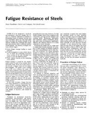
<strong>and</strong> pearlite matrix (Fig. 3). The graphite, be<strong>in</strong>g a<br />
major nonmetallic constituent <strong>in</strong> the gray iron,<br />
provides a tortuous path for sound to travel<br />
through the material. With so many flakes, sound<br />
waves are easily reflected <strong>and</strong> the sound damp-<br />
ened over a relatively short distance. However,<br />
for the jaw crusher, damp<strong>in</strong>g capacity is not a<br />
requirement. In this case, an alloy white cast iron<br />
is selected because of its high hardness <strong>and</strong> wear<br />
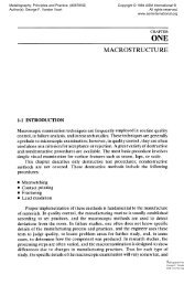
resistance. The white cast iron microstructure<br />
shown <strong>in</strong> Fig. 4 is graphite free <strong>and</strong> consists of<br />
martensite <strong>in</strong> a matrix of cementite. Both of these<br />
constituents are very hard <strong>and</strong> thus provide the<br />
required wear resistance. Thus, <strong>in</strong> this example<br />
the gray cast iron would not meet the require-<br />
ments for the jaws of a crusher <strong>and</strong> the white cast<br />
iron would not meet the requirements for the<br />
lathe hous<strong>in</strong>g.<br />
Role of Microstructure<br />
In steels <strong>and</strong> cast irons, the microstructural<br />
constituents have the names ferrite, pearlite,<br />
ba<strong>in</strong>ite, martensite, cementite, <strong>and</strong> austenite. In<br />
most all other metallic systems, the constituents<br />
are not named, but are simply referred to by a<br />
Greek letter (ct, 13, Y, etc.) derived from the loca-<br />
tion of the constituent on a phase diagram. Fer-<br />
rous alloy constituents, on the other h<strong>and</strong>, have<br />
been widely studied for more than 100 years. In<br />
the early days, many of the <strong>in</strong>vestigators were<br />
petrographers, m<strong>in</strong><strong>in</strong>g eng<strong>in</strong>eers, <strong>and</strong> geologists.<br />
Because m<strong>in</strong>erals have long been named after<br />
their discoverer or place of orig<strong>in</strong>, it was natural<br />
to similarly name the constituents <strong>in</strong> steels <strong>and</strong><br />
cast irons.<br />
It can be seen that the four examples described<br />
above have very different microstructures: the<br />
structural steel has a ferrite plus pearlite micro-<br />
structure; the rail steel has a fully pearlitic mi-<br />
crostructure; the mach<strong>in</strong>e hous<strong>in</strong>g (lathe) has a<br />
ferrite plus pearlite matrix with graphite flakes;<br />
<strong>and</strong> the jaw crusher microstructure conta<strong>in</strong>s<br />
martensite <strong>and</strong> cementite. In each case, the mi-<br />
crostructure plays the primary role <strong>in</strong> provid<strong>in</strong>g<br />
the properties desired for each application. From<br />
these examples, one can see how material proper-<br />
ties can be tailored by microstructural manipula-<br />
tion or alteration. Knowledge about microstruc-<br />
ture is thus paramount <strong>in</strong> component design <strong>and</strong><br />
alloy development. In the paragraphs that follow,<br />
each microstructural constituent is described<br />
with particular reference to the properties that<br />
can be developed by appropriate manipulation of<br />
the microstructure through deformation (e.g., hot<br />
<strong>and</strong> cold roll<strong>in</strong>g) <strong>and</strong> heat treatment. Further de-
156 / <strong>Structure</strong>/<strong>Property</strong> <strong>Relationships</strong> <strong>in</strong> <strong>Irons</strong> <strong>and</strong> Steels<br />
tails about these microstructural constituents can<br />
be found <strong>in</strong> Ref 2 to 6.<br />
Ferrite<br />
A wide variety of steels <strong>and</strong> cast irons fully<br />
exploit the properties of ferrite. However, only a<br />
few commercial steels are completely ferritic. An<br />
example of the microstructure of a fully ferritic,<br />
ultralow carbon steel is shown <strong>in</strong> Fig. 5.<br />
Ferrite is essentially a solid solution of iron<br />
conta<strong>in</strong><strong>in</strong>g carbon or one or more alloy<strong>in</strong>g ele-<br />
ments such as silicon, chromium, manganese,<br />
<strong>and</strong> nickel. There are two types of solid solu-<br />
tions: <strong>in</strong>terstitial <strong>and</strong> substitutional. In an <strong>in</strong>ter-<br />
stitial solid solution, elements with small atomic<br />
diameter, for example, carbon <strong>and</strong> nitrogen, oc-<br />
cupy specific <strong>in</strong>terstitial sites <strong>in</strong> the body-cen-<br />
tered cubic (bcc) iron crystall<strong>in</strong>e lattice. These<br />
sites are essentially the open spaces between the<br />
larger iron atoms. In a substitutional solid solu-<br />
tion, elements of similar atomic diameter replace<br />
or substitute for iron atoms. The two types of<br />
solid solutions impart different characteristics to<br />
ferrite. For example, <strong>in</strong>terstitial elements like<br />
carbon <strong>and</strong> nitrogen can easily diffuse through<br />
the open bcc lattice, whereas substitutional ele-<br />
ments like manganese <strong>and</strong> nickel diffuse with<br />
great difficulty. Therefore, an <strong>in</strong>terstitial solid<br />
solution of iron <strong>and</strong> carbon responds quickly dur-<br />
<strong>in</strong>g heat treatment, whereas substitutional solid<br />
solutions behave sluggishly dur<strong>in</strong>g heat treat-<br />
ment, such as <strong>in</strong> homogenization.<br />
Accord<strong>in</strong>g to the iron-carbon phase diagram<br />
(Fig. 6a), very little carbon (0.022% C) can dis-<br />
solve <strong>in</strong> ferrite (ctFe), even at the eutectoid tem-<br />
perature of 727 °C (1330 °F). (The iron-carbon<br />
phase diagram <strong>in</strong>dicates the phase regions that<br />
exist over a wide carbon <strong>and</strong> temperature range.<br />
The diagram represents equilibrium conditions.<br />
Figure 6(b) shows an exp<strong>and</strong>ed iron-carbon dia-<br />
gram with both the euteetoid <strong>and</strong> eutectic re-<br />
gions.) At room temperature, the solubility is an<br />
order of magnitude less (below 0.005% C). How-<br />
ever, even at these small amounts, the addition of<br />
carbon to pure iron <strong>in</strong>creases the room-tempera-<br />
ture yield strength of iron by more than five<br />
times, as seen <strong>in</strong> Fig. 7. If the carbon content<br />
exceeds the solubility limit of 0.022%, the car-<br />
bon forms another phase called cementite (Fig.<br />
8). Cementite is also a constituent of pearlite, as<br />
seen <strong>in</strong> Fig. 9. The role of cementite <strong>and</strong> pearlite<br />
on the mechanical properties of steel is discussed<br />
below.<br />
The <strong>in</strong>fluence of solid-solution elements on the<br />
yield strength of ferrite is shown <strong>in</strong> Fig. 10. Here<br />
one can clearly see the strong effect of carbon on<br />
<strong>in</strong>creas<strong>in</strong>g the strength of ferrite. Nitrogen, also<br />
an <strong>in</strong>terstitial element, has a similar effect. Phos-<br />
phorus is also a ferrite strengthener. In fact, there<br />
are commercially available steels conta<strong>in</strong><strong>in</strong>g<br />
phosphorus (up to 0.12% P) for strengthen<strong>in</strong>g.<br />
These steels are the rephosphorized steels (type<br />
1211 to 1215 series). Mechanical property data<br />
for these steels can be found <strong>in</strong> Table 1.<br />
In Fig. 10, the substitutional solid solution ele-<br />
ments of silicon, copper, manganese, molybde-<br />
num, nickel, alum<strong>in</strong>um, <strong>and</strong> chromium are shown<br />
to have far less effect as ferrite strengtheners<br />
than the <strong>in</strong>terstitial elements. In fact, chromium,<br />
nickel, <strong>and</strong> alum<strong>in</strong>um <strong>in</strong> solid solution have very<br />
little <strong>in</strong>fluence on the strength of ferrite.<br />
In addition to carbon (<strong>and</strong> other solid-solution<br />
elements), the strength of a ferritic steel is also<br />
]'able 1 (cont<strong>in</strong>ued)<br />
Steel Condition<br />
Low-alloy steels(b)<br />
1340 Normalized at 870 °C (1600 °F) 834<br />
Annealed at 800 °C (1475 °F) 703<br />
3140 Normalized at 870 °C (1600 oF) 889<br />
Annealed at 815 °C (1500 °F) 690<br />
4130 Normalized at 870 °C (1600 °F) 670<br />
Annealed at 865 °C (1585 °F) 560<br />
Water quenched from 855 °C (1575 °F) 1040<br />
<strong>and</strong> tempered at 540 °C (1000 °F)<br />
4140 Normalized at 870 °C (1600 oF) 1020<br />
Annealed at 815 °C (1500 °F) 655<br />
Water quenched from 845 °C ( 1550 °F) 1075<br />
<strong>and</strong> tempered at 540 °C (1000 °F)<br />
4150 Normalized at 870 °C ( 1600 °F) 1160<br />
Annealed at 830 °C (1525 °F) 731<br />
oil quenched from 830 °C (1525 °F) 1310<br />
<strong>and</strong> tempered at 540 °C (1000 °F)<br />
4320 Normalized at 895 °C (1640 oF) 793<br />
Annealed at 850 °C (1560 °F) 580<br />
4340 Normalized at 870 °C (1600 oF) 1282<br />
Annealed at 810 °C (1490 oF) 745<br />
Oil quenched from 800 °C (1475 °F) 1207<br />
<strong>and</strong> tempered at 540 °C (1000 °F)<br />
4419 Normalized at 955 °C (1750 oF) 515<br />
Annealed at 915 °C (1675 °F) 450<br />
4620 Normalized at 900 °C (1650 oF) 570<br />
Annealed at 855 °C (1575 oF) 510<br />
4820 Normalized at 860 °C (1580 oF) 758<br />
Annealed at 815 °C (1500 °F) 685<br />
5140 Normalized at 870 °C (1600 oF) 793<br />
Annealed at 830 °C (1525 °F) 570<br />
Oil quenched from 845 °C (1550 °F) 972<br />
<strong>and</strong> tempered at 540 °C (1000 °F)<br />
5150 Normalized at 870 °C (1600 oF) 869<br />
Annealed at 825 °C (1520 oF) 675<br />
Oil quenched from 830 °C (1525 °F) 1055<br />
<strong>and</strong> tempered at 540 °C (1000 °F)<br />
5160 Normalized at 855 °C (1575 oF) 1025<br />
Annealed at 815 °C (1495 oF) 724<br />
Oil quenched from 830 °C (1525 °F) 1145<br />
<strong>and</strong> tempered at 540 °C (1000 oF)<br />
6150 Normalized at 870 °C (1600 oF) 938<br />
Annealed at 815 °C (1500 oF) 670<br />
Oil quenched from 845 °C (1550 °F) 1200<br />
<strong>and</strong> tempered at 540 °C (1000 oF)<br />
8620 Normalized at 915 °C 0675 °F) 635<br />
Annealed at 870 °C (1600 oF) 540<br />
8630 Normalized at 870 °C (1600 oF) 650<br />
Annealed at 845 °C (1550 °F) 565<br />
Water quenched from 845 °C (1550 °F) 931<br />
<strong>and</strong> tempered at 540 °C (1000 °F)<br />
8650 Normalized at 870 °C (1600) 1025<br />
Annealed at 795 °C ( 1465 °F) 715<br />
oil quenched from 800 °C (1475 °F) 1185<br />
<strong>and</strong> tempered at 540 °C ( 1000 °F)<br />
8740 Normalized at 870 °C (1600 oF) 931<br />
Annealed at 815 °C (1500 oF) 696<br />
Oil quenched from 830 °C ( 1525 °F) 1225<br />
<strong>and</strong> tempered at 540 °C (1000 oF)<br />
9255 Normalized at 900 °C ( 1650 oF) 931<br />
Annealed at 845 °C (1550 oF) 779<br />
Oil quenched from 885 °C (1625 °F) 1130<br />
<strong>and</strong> tempered at 540 °C ( 1000 oF)<br />
9310 Normalized at 890 °C (1630 °F) 910<br />
Annealed at 845 °C (1550 oF) 820<br />
Ferritie sta<strong>in</strong>less steels(b)<br />
405 Annealed bar<br />
Cold draw n bar<br />
409 Annealed bar<br />
430 Annealed bar<br />
Tensile Yield<br />
strength strength<br />
MPa ksi MPa ksi<br />
Elongatba<br />
<strong>in</strong>SOnma, l~lt~tion Hardm~<br />
% ~a area, % lib<br />
121 558 81 22.0 63 248<br />
102 434 63 25.5 57 207<br />
129 600 87 19.7 57 262<br />
100 420 61 24.5 51 197<br />
97 435 63 25.5 59.5 197<br />
81 460 67 21.5 59.6 217<br />
151 979 142 18.1 63.9 302<br />
148 655 95 17.7 46.8 302<br />
95 915 60 25.7 56,9 197<br />
156 986 143 15.5 56,9 311<br />
168 731 106 11.7 30,8 321<br />
106 380 55 20.2 40,2 197<br />
190 1215 176 13.5 47.2 375<br />
115 460 67 20.8 51 235<br />
84 425 62 29.0 58 163<br />
186 862 125 12.2 36.3 363<br />
108 470 68 22.0 50.0 217<br />
175 1145 166 14.2 45.9 352<br />
75 350 51 32.5 69.4 143<br />
65 330 48 31.2 62.8 121<br />
83 365 53 29.0 66.7 174<br />
74 370 54 31.3 60.3 149<br />
110 485 70 24.0 59.2 229<br />
99 460 67 22.3 58.8 197<br />
115 470 68 22.7 59.2 229<br />
83 290 42 28.6 57.3 167<br />
141 841 122 18.5 58.9 293<br />
126 530 77 20.7 58.7 255<br />
98 360 52 22.0 43.7 197<br />
159 1000 145 16.4 52.9 311<br />
149 650 94 18.2 50.7 285<br />
105 275 40 17.2 30.6 197<br />
166 1005 146 14.5 45.7 341<br />
136 615 89 21.8 61.0 269<br />
97 415 60 23.0 48.4 197<br />
174 1160 168 14.5 48.2 352<br />
92 360 52 26.3 59.7 183<br />
78 385 56 31.3 62.1 149<br />
94 425 62 23.5 53.5 187<br />
82 370 54 29.0 58.9 156<br />
135 850 123 18.7 59.6 269<br />
149 690 100 14 45.0 302<br />
104 385 56 22.5 46.0 212<br />
172 1105 160 14.5 49.1 352<br />
135 605 88 16.0 47.9 269<br />
101 415 60 22.2 46.4 201<br />
178 1130 164 16.0 53.0 352<br />
135 580 84 19.7 43.4 269<br />
113 485 70 21.7 41.1 229<br />
164 924 134 16.7 38.3 321<br />
132 570 83 18.8 58.1 269HRB<br />
119 450 65 17.3 42.1 241HRB<br />
483 70 276 40 30 60 150<br />
586 85 483 70 20 60 185<br />
450 65 240 35 25 75HRB<br />
517 75 310 45 30 --65" 155<br />
(confnued)<br />
(a) All values are estimated m<strong>in</strong>imum values; type 1100 series steels are rated on the basis of 0.10% max Si or coarse-gra<strong>in</strong> melt-<br />
<strong>in</strong>g practice; the mechanical properties shown are expected m<strong>in</strong>imums for the sizes rang<strong>in</strong>g from 19 to 31.8 mm (0.75 to 1.25<br />
<strong>in</strong>.). (b) Most data are for 25 mm (1 <strong>in</strong>.) diam bar. Source: Ref I
Table 1 (cont<strong>in</strong>ued)<br />
Tensile<br />
strength<br />
Steel Ccmdition MPa ksi<br />
Ferritic sta<strong>in</strong>less steels(b) (cont<strong>in</strong>ued)<br />
430 (cont'd) Annealed <strong>and</strong> cold drawn 586 85<br />
442 Annealed bar 515 75<br />
Annealed at 815 °C (1500 °F) <strong>and</strong> cold 545 79<br />
worked<br />
446 Annealed bar 550 80<br />
Annealed at 815 °C (1500 °F) <strong>and</strong> cold 607 88<br />
drawn<br />
Martensilic sta<strong>in</strong>less steels(b)<br />
403 Annealed bar 515 75<br />
Tempered bar 765 111<br />
410 Oil quenched from 980 °C ( 1800 °F); 1085 158<br />
tempered at 540 °C (1000 °F);.16 nun<br />
(0.625 <strong>in</strong>.) bar<br />
Oil quenched from 980 °C (1800 °F); 1525 221<br />
tempered at 40 °C (104 °F); 16 mm<br />
(0.625 <strong>in</strong>.) bar<br />
414 Annealed bar 795 115<br />
Cold drawn bar 895 130<br />
Oil quenched from 980 °C (1800 °F); 1005 146<br />
tempered at 650 °C (1200 oF)<br />
420 Annealed bar 655 95<br />
Annealed <strong>and</strong> cold drawn 760 110<br />
431 Annealed bar 860 125<br />
Annealed <strong>and</strong> cold drawn 895 130<br />
Oil quenched from 980 °C (1800 °F); 831 121<br />
tempered at 650 °C (1200 oF)<br />
Oil quenched from 980 °C (1800 °F); 1435 208<br />
tempered at 40 °C (104 °F)<br />
440C Annealed bar 760 110<br />
Annealed <strong>and</strong> cold drawn bar 860 125<br />
Hardened <strong>and</strong> tempered at 315 °C 1970 285<br />
(6OO °F)<br />
Austenitle sta<strong>in</strong>less steels(b)<br />
201 Annealed 760 110<br />
50% hard 1035 150<br />
Full hard 1275 185<br />
Extra hard 1550 225<br />
202 Annealed bar 515 75<br />
Annealed sheet 655 95<br />
50% hard sheet 1030 150<br />
301 Annealed 725 105<br />
50% hard 1035 150<br />
Full hard 1415 205<br />
302 Annealed strip 620 90<br />
25% hard strip 860 125<br />
Annealed bar 585 85<br />
303 Annealed bar 620 90<br />
Colddrawn 690 100<br />
304 Annealed bar 585 85<br />
Annealed <strong>and</strong> cold drawn 690 100<br />
Cold-drawn high tensile 860 125<br />
305 Annealed sheet 585 85<br />
308 Annealed bar 585 85<br />
309 Annealed bar 655 95<br />
310 Annealed sheet 620 90<br />
Annealed bar 655 95<br />
314 Annealed bar 689 100<br />
316 Annealed sheet 580 84<br />
Annealed bar 550 80<br />
Annealed <strong>and</strong> cold-drawn bar 620 90<br />
317 Annealed sheet 620 90<br />
Annealed bar 585 85<br />
321 Annealed sheet 620 90<br />
Annealed bar 585 85<br />
Annealed <strong>and</strong> cold-drawn bar 655 95<br />
330 Annealed sheet 550 80<br />
Annealed bar 585 85<br />
347 Annealed sheet 655 95<br />
Annealed bar 620 90<br />
(cont<strong>in</strong>ued)<br />
Yield<br />
strength<br />
MPa ksi<br />
Elongation<br />
<strong>in</strong> 50ram,<br />
%<br />
483 70 20 65 185<br />
310 45 30 50 160<br />
427 62 35.5 79 92HRC<br />
345 50 25 45 86HRB<br />
462 67 26 64 96HRB<br />
275 40 35 70 82HRB<br />
585 85 23 67 97HRB<br />
1005 146 13 70 ...<br />
1225 178 15 64 45HRB<br />
620 90 20 60 235<br />
795 115 15 58 270<br />
800 116 19 58 ...<br />
345 50 25 55 195<br />
690 100 14 40 228<br />
655 95 20 55 260<br />
760 110 15 35 270<br />
738 107 20 64 ...<br />
1140 166 17 59 45HRC<br />
450 65 14 25 97HRB<br />
690 100 7 20 260<br />
1900 275 2 10 580<br />
380 55 52 ... 87HRB<br />
760 ll0 12 ... 32HRC<br />
965 140 8 ... 41HRC<br />
1480 215 1 ... 43HRC<br />
275 40 40 ......<br />
310 45 40 ......<br />
760 110 10 _ ...<br />
275 40 60 70' ...<br />
655 95 54 61 ...<br />
1330 193 6 ...<br />
275 40 55 ... 80HRB<br />
515 75 12 _ 25HRC<br />
240 35 60 70" 80HRB<br />
240 35 50 55 160<br />
415 60 40 53 228<br />
235 34 60 70 149<br />
415 60 45 ... 212<br />
655 95 25 ... 275<br />
260 38 50 _ 80HRB<br />
205 30 55 65' 150<br />
275 40 45 65 83HRB<br />
310 45 45 _ 85HRB<br />
275 40 45 65' 160<br />
345 50 45 60 180<br />
290 42 50 _ 79HRB<br />
240 35 60 70" 149<br />
415 60 45 65 190<br />
275 40 45 ... 85HRB<br />
275 40 50 ... 160<br />
240 35 45 _ 80HRB<br />
240 35 55 65' 150<br />
415 60 40 60 185<br />
260 38 40 ... ...<br />
290 42 45 ... 80HRB<br />
275 40 45 _ 85HRB<br />
240 35 50 65" 160<br />
(a) All values are estimated m<strong>in</strong>imum values; type 1100 series steels are rated on the basis of 0.10% max Si or coarse-gra<strong>in</strong> melt-<br />
<strong>in</strong>g practice; the mechanical properties shown are expected m<strong>in</strong>imums for the sizes rang<strong>in</strong>g from 19 to 31.8 mm (0.75 to 1.25<br />
<strong>in</strong>.). (b) Most data are for 25 mm (1 <strong>in</strong>.) diam bar. Source: Ref 1<br />
<strong>Structure</strong>/<strong>Property</strong> <strong>Relationships</strong> <strong>in</strong> <strong>Irons</strong> <strong>and</strong> Steels / 157<br />
determ<strong>in</strong>ed by its gra<strong>in</strong> size accord<strong>in</strong>g to the<br />
Hall-Petch relationship:<br />
Reduction Hardness, Gy = Go + kyd -1/2 (Eq 1)<br />
<strong>in</strong> area, % HB<br />
where Oy is the yield strength (<strong>in</strong> MPa), ~o is a<br />
constant, ky is a constant, <strong>and</strong> d is the gra<strong>in</strong> diame-<br />
ter (<strong>in</strong> mm).<br />
The gra<strong>in</strong> diameter is a measurement of size of<br />
the ferrite gra<strong>in</strong>s <strong>in</strong> the microstructure, for exam-<br />
ple, note the gra<strong>in</strong>s <strong>in</strong> the ultralow carbon steel <strong>in</strong><br />
Fig. 5. Figure 11 shows the Hall-Petch relation-<br />
ship for a low-carbon fully ferritic steel. This<br />
relationship is extremely important for under-<br />
st<strong>and</strong><strong>in</strong>g structure-property relationships <strong>in</strong><br />
steels. Control of gra<strong>in</strong> size through ther-<br />
momechanical treatment, heat treatment, <strong>and</strong>/or<br />
microalloy<strong>in</strong>g is vital to the control of strength<br />
<strong>and</strong> toughness of most steels. The role of gra<strong>in</strong><br />
size is discussed <strong>in</strong> more detail below.<br />
There is a simple way to stabilize ferrite,<br />
thereby exp<strong>and</strong><strong>in</strong>g the region of ferrite <strong>in</strong> the<br />
iron-carbon phase diagram, namely by the addi-<br />
tion of alloy<strong>in</strong>g elements such as silicon, chro-<br />
mium, <strong>and</strong> molybdenum. These elements are<br />
called ferrite stabilizers because they stabilize<br />
ferrite at room temperature through reduc<strong>in</strong>g the<br />
amount of y solid solution (austenite) with the<br />
formation of what is called a y-loop as seen at the<br />
far left <strong>in</strong> Fig. 12. This iron-chromium phase dia-<br />
gram shows that ferrite exists up above 12% Cr<br />
<strong>and</strong> is stable up to the melt<strong>in</strong>g po<strong>in</strong>t (liquidus<br />
temperature). An important fully ferritic family<br />
of steels is the iron-chromium ferritic sta<strong>in</strong>less<br />
steels. These steels are resistant to corrosion, <strong>and</strong><br />
are classified as type 405, 409, 429, 430, 434,<br />
436, 439, 442, 444, <strong>and</strong> 446 sta<strong>in</strong>less steels.<br />
These steels range <strong>in</strong> chromium content from 11<br />
to 30%. Additions of molybdenum, silicon, nio-<br />
bium, alum<strong>in</strong>um, <strong>and</strong> titanium provide specific<br />
properties. Ferritic sta<strong>in</strong>less steels have good<br />
ductility (up to 30% total elongation <strong>and</strong> 60%<br />
reduction <strong>in</strong> area) <strong>and</strong> formability, but lack<br />
strength at elevated temperatures compared with<br />
austenitic sta<strong>in</strong>less steels. Room-temperature<br />
yield strengths range from 170 to about 440 MPa<br />
(25 to 64 ksi), <strong>and</strong> room-temperature tensile<br />
strengths range from 380 to about 550 MPa (55<br />
to 80 ksi). Table 1 lists the mechanical properties<br />
of some of the ferritic sta<strong>in</strong>less steels. Type 409<br />
sta<strong>in</strong>less steel is widely used for automotive ex-<br />
haust systems. Type 430 free-mach<strong>in</strong><strong>in</strong>g sta<strong>in</strong>less<br />
steel has the best mach<strong>in</strong>ability of all sta<strong>in</strong>less<br />
steels other than that of a low-carbon, free-ma-<br />
ch<strong>in</strong><strong>in</strong>g martensitic sta<strong>in</strong>less steel (type 41.6).<br />
Another family of steels utiliz<strong>in</strong>g a ferrite sta-<br />
bilizer (y-loop) are the iron-silicon ferritic alloys<br />
conta<strong>in</strong><strong>in</strong>g up to about 6.5% Si (carbon-free).<br />
These steels are of commercial importance be-<br />
cause they have excellent magnetic permeability<br />
<strong>and</strong> low core loss. High-efficiency motors <strong>and</strong><br />
transformers are produced from these iron-sili-<br />
con electrical steels (alum<strong>in</strong>um can also substi-<br />
tute for silicon <strong>in</strong> them).<br />
Over the past 20 years or so, a new breed of<br />
very-low-carbon fully ferritic sheet steels has<br />
emerged for applications requir<strong>in</strong>g exceptional<br />
formability (see Fig. 5). These are the <strong>in</strong>tersti-<br />
tial-free (IF) steels for which carbon <strong>and</strong> nitro-<br />
gen are reduced <strong>in</strong> the steelmak<strong>in</strong>g process to<br />
very low levels, <strong>and</strong> any rema<strong>in</strong><strong>in</strong>g <strong>in</strong>terstitial<br />
carbon or nitrogen is tied up with small amounts<br />
of alloy<strong>in</strong>g elements (e.g., titanium or niobium)<br />
that form preferentially carbides <strong>and</strong> nitrides.
158/<strong>Structure</strong>/<strong>Property</strong> <strong>Relationships</strong> <strong>in</strong> <strong>Irons</strong> <strong>and</strong> Steels<br />
Table I (cont<strong>in</strong>ued)<br />
qI~mBe Yield<br />
st~ngth strength<br />
Sted C<strong>and</strong>~laa MPa k~ MPa I~<br />
Austenilic sta<strong>in</strong>less steels(b) (cont<strong>in</strong>ued)<br />
347 (eont'd) Annealed<strong>and</strong>colddrawnbar 690<br />
384 Annealed wire 1040 °C (1900 °F) 515<br />
Marag<strong>in</strong>g steels(b)<br />
18Ni(250) Annealed 965<br />
Aged bar 32 mm (1.25 <strong>in</strong>.) 1844<br />
Aged sheet 6 mm (0.25 <strong>in</strong>.) 1874<br />
18Ni(300) Annealed 1034<br />
Aged bar 32 mm (1.25 <strong>in</strong>.) 2041<br />
Aged sheet 6 mm (0.25 <strong>in</strong>.) 2169<br />
18Ni(350) Annealed 1140<br />
Aged bar 32 mm (l.25 <strong>in</strong>.) 2391<br />
Aged sheet 6 mm (0.25 <strong>in</strong>.) 2451<br />
Elongation<br />
<strong>in</strong>S0mm, Reduction Hardness,<br />
% <strong>in</strong> area, % liB<br />
100 450 65 40 60 212<br />
75 240 35 55 72 70HRB<br />
140 655 95 17 75 30 HRC<br />
269 1784 259 11 56.5 51.8 HRC<br />
272 1832 266 8 40.8 50.6HRC<br />
150 758 110 18 72 32HRC<br />
296 2020 293 11.6 55.8 54.7 HRC<br />
315 2135 310 7.7 35 55.1HRC<br />
165 827 120 18 70 35 HRC<br />
347 2348 341 7.6 33.8 58.4 HRC<br />
356 2395 347 3 15.4 57.7 HRC<br />
(a) All values are estimated m<strong>in</strong>imum values; type 1100 series steels ate rated on the basis of 0.10% max Si or coarse-gra<strong>in</strong> melt-<br />
<strong>in</strong>g practice; the mechanical properties shown are expected m<strong>in</strong>imums for the sizes rang<strong>in</strong>g from 19 to 31.8 mm (0.75 to 1.25<br />
<strong>in</strong>.). (b) Most data are for 25 mm (1 <strong>in</strong>.) diam bar. Some: Ref 1<br />
These steels have very low strength, but are used<br />
to produce components that are difficult or im-<br />
possible to form from other steels. Very-low-car-<br />
bon, fully ferritic steels (0.001% C) are now be-<br />
<strong>in</strong>g manufactured for automotive components<br />
that harden dur<strong>in</strong>g the pa<strong>in</strong>t-cur<strong>in</strong>g cycle. These<br />
steels are called bake-harden<strong>in</strong>g steels <strong>and</strong> have<br />
controlled amounts of carbon <strong>and</strong> nitrogen that<br />
comb<strong>in</strong>e with other elements, such as titanium<br />
<strong>and</strong> niobium, dur<strong>in</strong>g the bak<strong>in</strong>g cycle (175 °C, or<br />
350 °F, for 30 m<strong>in</strong>). The process is called ag<strong>in</strong>g,<br />
<strong>and</strong> the strength derives from the precipitation of<br />
titanium/niobium carbonitrides at the elevated<br />
temperature.<br />
Another form of very-low-carbon, fully ferritic<br />
steel is motor lam<strong>in</strong>ation steel. The carbon is re-<br />
moved from these steels by a process known as<br />
decarburization. The decarburized (carbon-free)<br />
ferritic steel has good permeability <strong>and</strong> suffi-<br />
ciently low core loss (not as low as the iron-sili-<br />
con alloys) to be used for electric motor lam<strong>in</strong>a-<br />
tions, that is, the stacked steel layers <strong>in</strong> the rotor<br />
<strong>and</strong> stator of the motor.<br />
As noted previously, a number of properties<br />
are exploited <strong>in</strong> fully ferritic steels:<br />
• Iron-silicon steels: Exceptional electrical<br />
properties<br />
• Iron-chromium steels: Good corrosion resis-<br />
tance<br />
• Interstitial-free steels: Exceptional forma-<br />
bility<br />
• Bake-harden<strong>in</strong>g steels: Strengthens dur<strong>in</strong>g<br />
pa<strong>in</strong>t cure cycle<br />
• Lam<strong>in</strong>ation steels: Good electrical properties<br />
PearlRe<br />
As the carbon content of steel is <strong>in</strong>creased be-<br />
yond the solubility limit (0.02% C) on the iron-<br />
carbon b<strong>in</strong>ary phase diagram, a constituent called<br />
pearlite forms. Pearlite is formed by cool<strong>in</strong>g the<br />
steel through the eutectoid temperature (the tem-<br />
perature of 727 °C <strong>in</strong> Fig. 6) by the follow<strong>in</strong>g<br />
reaction:<br />
Austenite ~ cementite + ferrite ffXl2)<br />
The cementite <strong>and</strong> ferrite form as parallel plates<br />
called lamellae (Fig. 13). This is essentially a<br />
composite microstructure consist<strong>in</strong>g of a very<br />
hard carbide phase, cementite, <strong>and</strong> a very soft <strong>and</strong><br />
ductile ferrite phase. A fully pearlitic microstruc-<br />
ture is formed at the eutectoid composition of<br />
0.78% C. As can be seen <strong>in</strong> Fig. 2 <strong>and</strong> 13, pearlite<br />
forms as colonies where the lamellae are aligned<br />
<strong>in</strong> the same orientation. The properties of fully<br />
pearlitic steels are determ<strong>in</strong>ed by the spac<strong>in</strong>g be-<br />
tween the ferrite-cementite lamellae, a dimension<br />
called the <strong>in</strong>terlamellar spac<strong>in</strong>g, X, <strong>and</strong> the colony<br />
size. A simple relationship for yield strength has<br />
been developed by Heller (Ref 10) as follows:<br />
fly = -85.9 + 8.3 (X -t/2) (Eq 3)<br />
where fly is the 0.2% offset yield strength (<strong>in</strong><br />
MPa) <strong>and</strong> X is the <strong>in</strong>terlamellar spac<strong>in</strong>g (<strong>in</strong> mm).<br />
Figure 14 shows Heller's plot of strength versus<br />
<strong>in</strong>terlamellar spac<strong>in</strong>g for fully pearlitic eutectoid<br />
steels.<br />
It has also been shown by Hyzak <strong>and</strong> Bernste<strong>in</strong><br />
(Ref 11) that strength is related to <strong>in</strong>terlamellar<br />
spac<strong>in</strong>g, pearlite colony size, <strong>and</strong> prior-austenite<br />
gra<strong>in</strong> size, accord<strong>in</strong>g to the follow<strong>in</strong>g relation-<br />
ship:<br />
YS = 52.3 + 2.18 (~-1/2) -0.4 (de -L'2) -2.88 (d-1/2)(Eq 4)<br />
where YS is the yield strength (<strong>in</strong> MPa), d e is the<br />
pearlite colony size (<strong>in</strong> mm), <strong>and</strong> d is the prior-<br />
austenite gra<strong>in</strong> size (<strong>in</strong> mm). From Eq 3 <strong>and</strong> 4, it<br />
can be seen that the steel composition does not<br />
have a major <strong>in</strong>fluence on the yield strength of a<br />
fully pearlitic eutectoid steel. There is some solid-<br />
Fig, 3 Microstructure of a gray cast iron with a ferrite-pearlite matrix. Note the graphite Fig. 4 Microstructure of an alloy white cast iron. White constituent is cementite <strong>and</strong> the<br />
flakes dispersed throughout the matrix. 4% picral etch. 320x. Courtesy of A.O. darker constituent is martensite with some reta<strong>in</strong>ed austenite. 4% picral etch.<br />
Benscoter, Lehigh University 250x. Courtesy ofA.O. Benscoter, Lehigh University
Fig. 5 Microstructure of a fully ferritic, ultralow carbon<br />
steel. Marshalls etch + HF, 300x. Courtesy of<br />
A.O. Benscoter, Lehigh University<br />
solution strengthen<strong>in</strong>g of the ferrite <strong>in</strong> the lamel-<br />
lar structure (see Fig. 10).<br />
The thickness of the cementite lamellae can<br />
also <strong>in</strong>fluence the properties of pearlite. F<strong>in</strong>e ce-<br />
mentite lamellae can be deformed, compared<br />
with coarse lamellae, which tend to crack dur<strong>in</strong>g<br />
deformation.<br />
Although fully pearlitic steels have high<br />
strength, high hardness, <strong>and</strong> good wear resis-<br />
tance, they also have poor ductility <strong>and</strong> tough-<br />
ness. For example, a low-carbon, fully ferritic<br />
¢D<br />
O.<br />
E<br />
1180<br />
1140<br />
1100<br />
1060<br />
1020<br />
980<br />
940<br />
900<br />
86O<br />
820<br />
780<br />
740<br />
700 /<br />
66O<br />
Fe<br />
steel will typically have a total elongation of<br />
more than 50%, whereas a fully pearlitic steel<br />
(e.g., type 1080) will typically have a total elon-<br />
gation of about 10% (see Table 1). A low-carbon<br />
fully ferritic steel will have a room-temperature<br />
Charpy V-notch impact energy of about 200 J<br />
(150 ft. lbf), whereas a fully pearlitic steel will<br />
have room-temperature impact energy of under<br />
10 J (7 ft. lbf). The transition temperature (i.e.,<br />
the temperature at which a material changes from<br />
ductile fracture to brittle fracture) for a fully<br />
pearlitic steel can be approximated from the fol-<br />
low<strong>in</strong>g relationship (Ref 11):<br />
TT = 217.84 - 0.83 (de -1/2) - 2.98(d -1"~) (Eq5)<br />
where TT is the transition temperature (<strong>in</strong> °C).<br />
From Eq 5, one can see that both the prior-<br />
austenite gra<strong>in</strong> size <strong>and</strong> pearlite colony size con-<br />
trol the transition temperature of a pearlitic steel.<br />
Unfortunately, the transition temperature of a<br />
fully pearlitic steel is always well above room<br />
temperature. This means that at room tempera-<br />
ture the general fracture mode is cleavage, which<br />
is associated with brittle fracture. Therefore,<br />
fully pearlitic steels should not be used <strong>in</strong> appli-<br />
cations where toughness is important. Also, pear-<br />
litic steels with carbon contents slightly or mod-<br />
erately higher than the eutectoid composition<br />
(called hypereutectoid steels) have even poorer<br />
toughness.<br />
From Eq 4 <strong>and</strong> 5, one can see that for pearlite,<br />
strength is controlled by <strong>in</strong>terlamellar spac<strong>in</strong>g,<br />
colony size, <strong>and</strong> prior-austenite gra<strong>in</strong> size, <strong>and</strong><br />
toughness is controlled by colony size <strong>and</strong> prior-<br />
Carbon, at.%<br />
1 2 3 4 5 6<br />
I I I I I I<br />
Fe-C equilibrium (experimental)<br />
- - Fe-Fe3C equilibrium (experimental)<br />
(~Fe)<br />
auatenite<br />
~912 °C , / "<br />
~ ~0¢F.) ferrite . ,-~<br />
%~ 770 °C (Curie temperature) -*°~<br />
.../<br />
.................. ~- - -'-~ 0.68 7<br />
I ~ 0.0206 ~ ~, .'°"<br />
0.0218 I<br />
I Ferrite + cementite<br />
I I I I<br />
0.1 0.2 0.3 0.4 0.5 0.6 0.7 0.8 0.9 1.0 1.1 1.2 1.3 1.4<br />
Carbon, wt%<br />
<strong>Structure</strong>/<strong>Property</strong> <strong>Relationships</strong> <strong>in</strong> <strong>Irons</strong> <strong>and</strong> Steels/159<br />
austenite gra<strong>in</strong> size. Unfortunately, these three<br />
factors are rather difficult to measure. To deter-<br />
m<strong>in</strong>e <strong>in</strong>terlamellar spac<strong>in</strong>g, a scann<strong>in</strong>g electron<br />
microscope (SEM), or a transmission electron<br />
microscope (TEM) is needed <strong>in</strong> order to resolve<br />
the spac<strong>in</strong>g, Generally, a magnification of<br />
10,000x is adequate, as seen <strong>in</strong> Fig. 13. Special<br />
statistical procedures have been developed to de-<br />
term<strong>in</strong>e an accurate measurement of the spac<strong>in</strong>g<br />
(Ref 12). The colony size <strong>and</strong> especially the<br />
prior-austenite gra<strong>in</strong> size are very difficult to<br />
measure <strong>and</strong> require a skilled metallographer us-<br />
<strong>in</strong>g the light microscope or SEM <strong>and</strong> special<br />
etch<strong>in</strong>g procedures.<br />
Because of poor ductility/toughness, there are<br />
only a few applications for fully pearlitic steels,<br />
<strong>in</strong>clud<strong>in</strong>g railroad rails <strong>and</strong> wheels <strong>and</strong> high-<br />
strength wire. By far, the largest tonnage applica-<br />
tion is for rails. A fully pearlitic rail steel pro-<br />
vides excellent wear resistance for railroad<br />
wheel/rail contact. Rail life is measured <strong>in</strong> mil-<br />
lions of gross tons (MGT) of travel <strong>and</strong> current<br />
rail life easily exceeds 250 MGT. The wear resis-<br />
tance of pearlite arises from the unique morphol-<br />
ogy of the ferrite-cementite lamellar composite<br />
where a hard constituent is embedded <strong>in</strong>to a soft-<br />
ductile constituent. This means that the hard ce-<br />
mentite plates do not abrade away as easily as the<br />
rounded cementite particles found <strong>in</strong> other steel<br />
microstructures, that is, tempered martensite <strong>and</strong><br />
ba<strong>in</strong>ite, which is discussed later. Wear resistance<br />
of a rail steel is directly proportional to hardness.<br />
This is shown <strong>in</strong> Fig. 15, which <strong>in</strong>dicates less<br />
weight loss as hardness <strong>in</strong>creases. Also, wear re-<br />
sistance (less weight loss) <strong>in</strong>creases as <strong>in</strong>ter-<br />
lamellar spac<strong>in</strong>g decreases, as shown <strong>in</strong> Fig. 16.<br />
7 8 9<br />
1154°C - ~...~ 2125<br />
2.08 I ~ J., "'" ~1,,/ 8 °C-'~ 2050<br />
.o"Y 211 -- 1975<br />
• *' Y<br />
• .~ -- 1900<br />
-- 1825<br />
-- 1750<br />
AUS tenite + cementite -- 1700<br />
-- 1625<br />
-- 1550<br />
-- 1475<br />
738 °C - 1400<br />
I --<br />
727 °C<br />
1325<br />
I - 1250<br />
1.5 1.6 1.7 1.8 1.9 2.0 2.1 2.2<br />
Fig. 6(a) Iron-carbon phase diagram show<strong>in</strong>g the austenite (y Fe) <strong>and</strong> ferrite (ocFe) phase regions <strong>and</strong> eutectoid composition <strong>and</strong> temperature. Dotted l<strong>in</strong>es represent iron-graphite equi-<br />
librium conditions <strong>and</strong> solid l<strong>in</strong>es represent iron-cementite equilibrium conditions. Only the solid l<strong>in</strong>es are important with respect to steels. Source: Ref 2<br />
u- o<br />
E
160/<strong>Structure</strong>/<strong>Property</strong> <strong>Relationships</strong> <strong>in</strong> <strong>Irons</strong> <strong>and</strong> Steels<br />
Thus, the most important microstructural pa-<br />
rameter for controll<strong>in</strong>g hardness <strong>and</strong> wear resis-<br />
tance is the pearlite <strong>in</strong>terlamellar spac<strong>in</strong>g. Fortu-<br />
nately, <strong>in</strong>terlamellar spac<strong>in</strong>g is easy to control<br />
<strong>and</strong> is dependent solely on transformation tem-<br />
perature.<br />
Figure 17 shows a cont<strong>in</strong>uous cool<strong>in</strong>g transfor-<br />
mation (CCT) diagram for a typical rail steel. A<br />
CCT diagram is a time versus temperature plot<br />
show<strong>in</strong>g the regions at which various constitu-<br />
cnts--ferdte, pearlite, ba<strong>in</strong>ite, <strong>and</strong> martensite--<br />
form dur<strong>in</strong>g the cont<strong>in</strong>uous cool<strong>in</strong>g of a steel<br />
component. Usually several cool<strong>in</strong>g curves are<br />
shown with the associated start <strong>and</strong> f<strong>in</strong>ish trans-<br />
formation temperatures of each constituent.<br />
These diagrams should not be confused with iso-<br />
thermal transformation (IT or TTT) diagrams,<br />
which are derived by rapidly quench<strong>in</strong>g very th<strong>in</strong><br />
specimens to various temperatures, <strong>and</strong> ma<strong>in</strong>ta<strong>in</strong>-<br />
<strong>in</strong>g that temperature (isothermal) until the speci-<br />
mens beg<strong>in</strong> to transform, partially transform, <strong>and</strong><br />
fully transform, at which time they are quenched<br />
to room temperature. An IT diagram does not<br />
represent the transformation behavior <strong>in</strong> most<br />
processes where steel parts are cont<strong>in</strong>uously<br />
cooled, that is, air cooled, <strong>and</strong> so forth.<br />
As shown <strong>in</strong> Fig. 17, the peadite transforma-<br />
tion temperature (<strong>in</strong>dicated by the pearlite-start<br />
curve, Ps) decreases with <strong>in</strong>creas<strong>in</strong>g cool<strong>in</strong>g rate.<br />
The hardness of peaflite <strong>in</strong>creases with decreas-<br />
<strong>in</strong>g transformation temperature. Thus, <strong>in</strong> order to<br />
provide a rail steel with the highest hardness <strong>and</strong><br />
wear resistance, one must cool the rail from the<br />
austenite at the fastest rate possible to obta<strong>in</strong> the<br />
lowest transformation temperature. This is done<br />
<strong>in</strong> practice by a process known as head harden-<br />
<strong>in</strong>g, which is simply an accelerated cool<strong>in</strong>g proc-<br />
ess us<strong>in</strong>g forced air or water sprays to achieve<br />
the desired cool<strong>in</strong>g rate (Ref 15). Because only<br />
the head of the rail contacts the wheel of the<br />
railway car <strong>and</strong> locomotive, only the head re-<br />
quires the higher hardness <strong>and</strong> wear resistance.<br />
Another application for a fully pearlitic steel is<br />
high-strength wire (e.g., piano wire). Aga<strong>in</strong>, the<br />
composite morphology of lamellar ferrite <strong>and</strong> ce-<br />
mentite is exploited, this time dur<strong>in</strong>g wire draw-<br />
<strong>in</strong>g. A fully pearlitic steel rod is heat treated by a<br />
process known as patent<strong>in</strong>g. Dur<strong>in</strong>g patent<strong>in</strong>g,<br />
1~ M 3270<br />
1~ 3090<br />
1 ! 2730<br />
GFe<br />
1~ 2550<br />
11 2010<br />
lC 1830 ~<br />
E<br />
i ~ E 1470<br />
7 1290<br />
-~ 930<br />
4 750<br />
3 570<br />
I P_~<br />
30<br />
Fe 0.5 1.0 1.5 2.0 2.5 3.0 3.5 4.0 4.5 5.0 5.5 6.0 6.5 7.0<br />
Carbon, wt%<br />
Fig. 6(b) Exp<strong>and</strong>ed iron-carbon phase diagram show<strong>in</strong>g both the eutectoid (shown <strong>in</strong> Fig. 6a) <strong>and</strong> eutectic regions.<br />
Dotted l<strong>in</strong>es represent iron-graphite equilibrium conditions <strong>and</strong> solid l<strong>in</strong>es represent iron-cementite equilib-<br />
rium conditions. The solid l<strong>in</strong>es at the eutectic are important to white cast irons <strong>and</strong> the dotted l<strong>in</strong>es are important to gray<br />
cast irons. Source: Ref 2<br />
2910<br />
2370<br />
2190<br />
rILE[<br />
the rod is transformed at a temperature of about<br />
540 °C (1000 °F) by pass<strong>in</strong>g it through a lead or<br />
salt bath at this temperature. This develops a<br />
microstructure with a very f<strong>in</strong>e pearlite <strong>in</strong>ter-<br />
lamellar spac<strong>in</strong>g because the transformation<br />
takes place at the nose of the CCT diagram, that<br />
is, at the lowest possible pearlite transformation<br />
temperature (see Fig. 17). The rod is then cold<br />
drawn to wire. Because of the very f<strong>in</strong>e <strong>in</strong>ter-<br />
lamellar spac<strong>in</strong>g, the ferrite <strong>and</strong> cementite lamel-<br />
lae become aligned along the wire axis dur<strong>in</strong>g<br />
the deformation process. Also, the f<strong>in</strong>e ccmentite<br />
lamella tend to bend <strong>and</strong> deform as the wire is<br />
elongated dur<strong>in</strong>g draw<strong>in</strong>g. The result<strong>in</strong>g wire is<br />
one of the strongest commercial products avail-<br />
able; for example, a commercial 0.1 mm (0.004<br />
<strong>in</strong>.) diam wire can have a tensile strength <strong>in</strong> the<br />
range of 3.0 to 3.3 GPa (439 to 485 ksi), <strong>and</strong> <strong>in</strong><br />
special cases a tensile strength as high as 4.8<br />
GPa (696 ksi) can be obta<strong>in</strong>ed. These wires are<br />
used <strong>in</strong> musical <strong>in</strong>struments because of the sound<br />
quality developed from the high tensile stresses<br />
applied <strong>in</strong> str<strong>in</strong>g<strong>in</strong>g a piano <strong>and</strong> viol<strong>in</strong> <strong>and</strong> are<br />
also used <strong>in</strong> wire rope cables for suspension<br />
bridges.<br />
Ferrite-Pearlite<br />
The most common structural steels produced<br />
have a mixed ferrite-pearlite microstructure.<br />
Their applications <strong>in</strong>clude beams for bridges <strong>and</strong><br />
high-rise build<strong>in</strong>gs, plates for ships, <strong>and</strong> re<strong>in</strong>-<br />
forc<strong>in</strong>g bars for roadways. These steels are rela-<br />
tively <strong>in</strong>expensive <strong>and</strong> are produced <strong>in</strong> large ton-<br />
nages. They also have the advantage of be<strong>in</strong>g<br />
able to be produced with a wide range of proper-<br />
ties. The microstructure of typical ferrite-pearlite<br />
steels is shown <strong>in</strong> Fig. 18.<br />
In most ferrite-pearlite steels, the carbon con-<br />
tent <strong>and</strong> the gra<strong>in</strong> size determ<strong>in</strong>e the micro-<br />
structure <strong>and</strong> result<strong>in</strong>g properties. For example,<br />
Fig. 19 shows the effect of carbon on tensile <strong>and</strong><br />
impact properties. The ultimate tensile strength<br />
steadily <strong>in</strong>creases with <strong>in</strong>creas<strong>in</strong>g carbon con-<br />
tent. This is caused by the <strong>in</strong>crease <strong>in</strong> the volume<br />
fraction of pearlite <strong>in</strong> the microstructure, which<br />
has a strength much higher than that of ferrite.<br />
Thus, <strong>in</strong>creas<strong>in</strong>g the volume fraction of pearlite<br />
has a profound effect on <strong>in</strong>creas<strong>in</strong>g tensile<br />
strength.<br />
However, as seen <strong>in</strong> Fig. 19, the yield strength<br />
is relatively unaffected by carbon content, ris<strong>in</strong>g<br />
from about 275 MPa (40 ksi) to about 415 MPa<br />
(60 ksi) over the range of carbon content shown.<br />
This is because yield<strong>in</strong>g <strong>in</strong> a ferrite-pearlite steel<br />
is controlled by the fcrrite matrix, which is gen-<br />
erally considered to be the cont<strong>in</strong>uous phase (ma-<br />
"~ 35 241 ~:<br />
-'~ 25 ~' ..... 172<br />
"N,<br />
/ 103=<br />
0<br />
o~ 10 ~<br />
o.<br />
o<br />
0 0.001 0.002 0.003<br />
Carbon, wt%<br />
0.004 0.005 o<br />
6<br />
Fig, 7 Increase <strong>in</strong> room-temperature yield strength of<br />
iron with small additions of carbon. Source: Ref 7<br />
O3
Fig. 8 Photomic.rograph of an annealed low-carbon sheet steel with gra<strong>in</strong>-boundary ce-<br />
mentite. 2% nital + 4% picral etch. 1000x<br />
trix) <strong>in</strong> the microstructure. Therefore, pearlite<br />
plays only a m<strong>in</strong>or role <strong>in</strong> yield<strong>in</strong>g behavior.<br />
From Fig. 19, one can also see that ductility, as<br />
represented by reduction <strong>in</strong> area, steadily de-<br />
creases with <strong>in</strong>creas<strong>in</strong>g carbon content. A steel<br />
with 0.10% C has a reduction <strong>in</strong> area of about<br />
75%, whereas a steel with 0.70% C has a reduc-<br />
tion <strong>in</strong> area of only 25%. Percent total elongation<br />
would show a similar trend, however, with values<br />
much less than percent reduction <strong>in</strong> area.<br />
Much work has been done to develop empirical<br />
equations for ferrite-pearlite steels that relate<br />
strength <strong>and</strong> toughness to microstructural fea-<br />
tures, for example, gra<strong>in</strong> size <strong>and</strong> percent of<br />
pearlite as well as composition. One such equa-<br />
tion for ferrite-pearlitc steels under 0.25% C is as<br />
follows (Ref 16):<br />
YS = 53.9 + 32.34 (Mn) + 83.2(Si)<br />
+ 354.2(Nf) + 17.4(d-U2) (Eq 6)<br />
where Mn is the manganese content (%), Si is the<br />
silicon content (%), Nf is the free nitrogen content<br />
(%), <strong>and</strong> d is the ferrite gra<strong>in</strong> size (<strong>in</strong> mm). Equa-<br />
tion 6 shows that carbon content (percent pearlite)<br />
4-375<br />
+225<br />
.--~_m+150<br />
"~ +75<br />
o 0<br />
-75<br />
I<br />
C <strong>and</strong> N<br />
/<br />
y -- Ni <strong>and</strong> AI<br />
0 0.5 1.0 1.5 2.0 2.5 3.0<br />
Alloy content, wt%<br />
Fig, 10 Influence of solid-solution elements on the<br />
changes <strong>in</strong> yield stress of low-carbon ferritic<br />
steels. Source: Ref 5<br />
Si<br />
has no effect on yield strength, whereas the yield<br />
strength <strong>in</strong> Fig. 19 <strong>in</strong>creases somewhat with car-<br />
bon content. Accord<strong>in</strong>g to Eq 6, manganese, sili-<br />
con, <strong>and</strong> nitrogen have a pronounced effect on<br />
yield strength, as does gra<strong>in</strong> size. However, <strong>in</strong><br />
most ferrite-pearlite steels nitrogen is quite low<br />
(under 0.010%) <strong>and</strong> thus has m<strong>in</strong>imal effect on<br />
yield strength. In addition, as discussed below,<br />
nitrogen has a detrimental effect on impact prop-<br />
erties.<br />
The regression equation for tensile strength for<br />
the same steels is as follows (Ref 16):<br />
TS = 294,1 + 27.7(Mn) + 83.2(Si)<br />
+ 3.9(P) + 7.7(d -lt2) (F-4 7)<br />
where TS is the tensile strength (<strong>in</strong> MPa) <strong>and</strong> P is<br />
pearlite content (%). Thus, <strong>in</strong> dist<strong>in</strong>ction to yield<br />
strength, the percentage of pearlite <strong>in</strong> the micro-<br />
structure has an important effect on tensile<br />
strength.<br />
Toughness of ferrite-pearlite steels is also an<br />
important consideration <strong>in</strong> their use. It has long<br />
been known that the absorbed energy <strong>in</strong> a Charpy<br />
V-notch test is decreased by <strong>in</strong>creas<strong>in</strong>g carbon<br />
content, as seen <strong>in</strong> Fig. 20. In this graph of im-<br />
Fig. 11<br />
&<br />
600<br />
500<br />
400<br />
~ 300<br />
200<br />
100<br />
<strong>Structure</strong>/<strong>Property</strong> <strong>Relationships</strong> <strong>in</strong> <strong>Irons</strong> <strong>and</strong> Steels / 161<br />
Fig. 9 Photomicrograph of pearlite (dark constituent) <strong>in</strong> a low-carbon steel sheet. 2% ni-<br />
tal + 4% picral etch. 1000x<br />
pact energy versus test temperature, the shelf en-<br />
ergy decreases from about 200 J (150 ft • lbf) for<br />
a 0.11% C steel to about 35 J (25 ft. lbf) for a<br />
0.80% C steel. Also, the transition temperature<br />
<strong>in</strong>creases from about -50 to 150 °C (-60 to 300<br />
°F) over this same range of carbon content. The<br />
effect of carbon is due ma<strong>in</strong>ly to its effect on the<br />
percentage of pearlite <strong>in</strong> the microstructurc. This<br />
is reflected <strong>in</strong> the regression equation for transi-<br />
tion temperature below (Ref 16):<br />
TT = -19 + 44(Si) + 700(N~/2)<br />
+ 2.2(P) - 11.5 (d -1/2) (F_.q 8)<br />
It can be seen <strong>in</strong> all these relationships that<br />
ferrite gra<strong>in</strong> size is an important parameter <strong>in</strong><br />
improv<strong>in</strong>g both strength <strong>and</strong> toughness. It can<br />
also be seen that while pearlite is beneficial for<br />
<strong>in</strong>creas<strong>in</strong>g tensile strength <strong>and</strong> nitrogen is benefi-<br />
cial for <strong>in</strong>creas<strong>in</strong>g yield strength, both are harm-<br />
ful to toughness. Therefore, methods to control<br />
the gra<strong>in</strong> size of ferrite-pearlite steels have rap-<br />
idly evolved over the past 25 years. The two most<br />
important methods to control gra<strong>in</strong> size are con-<br />
trolled roll<strong>in</strong>g <strong>and</strong> microalloy<strong>in</strong>g. In fact, these<br />
I I I I I I I I I I I I<br />
0 1 2 3 4 5 6 7 8 9 10 11 12<br />
Gra<strong>in</strong> diameter (d-l~), mm -1~<br />
Hall-Petch relationship <strong>in</strong> low-carbon ~mtic steels, souse: Ref 8<br />
80<br />
80<br />
"N.<br />
20 |
162 / <strong>Structure</strong>/<strong>Property</strong> <strong>Relationships</strong> <strong>in</strong> <strong>Irons</strong> <strong>and</strong> Steels<br />
Fig. 12<br />
oo<br />
(9<br />
¢:L<br />
E<br />
Chromium, at.%<br />
0 10 20 30 40 50 60 70<br />
20OO<br />
1800<br />
1600<br />
1400 - 1394 °C<br />
I I<br />
1538 °C 1516 °: ~ ......<br />
1200 - ~ (~Fe,Cr)<br />
1000 _(~Fe)//_12. 7<br />
oc/I<br />
21<br />
8001:-- -.7<br />
I -/ ( o I<br />
~nn I Magnetic "~ • "---- ..... I , "* ".<br />
oc<br />
80 90 100<br />
Itransformabon.-<br />
/<br />
o.'. ..................<br />
,, :<br />
475 o C<br />
=.." ...........................<br />
"-..<br />
".,..<br />
400 i r'1 °° I I I I I I I t "'~<br />
0 10 20 30 40 50 60 70 80 90<br />
Fe Chromium, wt%<br />
Iron-chromium phase diagram. Source: Ref 9<br />
methods are used <strong>in</strong> conjunction to produce<br />
strong, tough ferrite-pearlite steels.<br />
Controlled roll<strong>in</strong>g is a thermomechanical<br />
treatment <strong>in</strong> which steel plates are rolled below<br />
the recrystailization temperature of aastcnite.<br />
This process results <strong>in</strong> elongation of the austenite<br />
gra<strong>in</strong>s. Upon further roll<strong>in</strong>g <strong>and</strong> subsequent cool-<br />
<strong>in</strong>g to room temperature, the austenite-to-ferrite<br />
transformation takes place. The ferrite gra<strong>in</strong>s are<br />
restricted <strong>in</strong> their growth because of the "pan-<br />
cake" austeaite gra<strong>in</strong> morphology. This produces<br />
the f<strong>in</strong>e ferrite gra<strong>in</strong> size required for higher<br />
strength <strong>and</strong> toughness.<br />
Microalloy<strong>in</strong>g is the term applied to the addi-<br />
tion of small amounts of special alloy<strong>in</strong>g ele-<br />
ments (vanadium, niobium, or titanium) that aid<br />
I i I I I I I<br />
1863 °C<br />
100<br />
Cr<br />
<strong>in</strong> retard<strong>in</strong>g austenite recrystallization, thus al-<br />
low<strong>in</strong>g a wide w<strong>in</strong>dow of roll<strong>in</strong>g temperatures<br />
for controlled roll<strong>in</strong>g. Without retard<strong>in</strong>g recrys-<br />
tallization, as <strong>in</strong> normal hot roll<strong>in</strong>g, the pancake-<br />
type gra<strong>in</strong>s do not form <strong>and</strong> a f<strong>in</strong>e gra<strong>in</strong> size<br />
cannot be developed. Microalloyed steels are<br />
used <strong>in</strong> a wide variety of high tonnage applica-<br />
tions <strong>in</strong>clud<strong>in</strong>g structural steels for the construc-<br />
tion <strong>in</strong>dustry (bridges, multistory build<strong>in</strong>gs,<br />
etc.), re<strong>in</strong>forc<strong>in</strong>g bar, pipe for gas transmission,<br />
<strong>and</strong> numerous forg<strong>in</strong>g applications.<br />
Ba<strong>in</strong>ite<br />
Like pearlite, ba<strong>in</strong>itc is a composite of ferrite<br />
<strong>and</strong> cementitc. Unlike pearlite, the ferritc has an<br />
Fig, 13 SEM micrograph of pearlite show<strong>in</strong>g ferrile <strong>and</strong> cementite lamellae. 4% picral etch. 10, O00x<br />
acicular morphology <strong>and</strong> the carbides are dis-<br />
crete particles. Because of these morphological<br />
differences, ba<strong>in</strong>ite has much different property<br />
characteristics than pearlite. In general, ba<strong>in</strong>itic<br />
steels have high strength coupled with good<br />
toughness, whereas pearlitic steels have high<br />
strength with poor toughness.<br />
Another difference between baiaite <strong>and</strong> pearl-<br />
ite is the complexity of the ba<strong>in</strong>ite morphologies<br />
compared with the simple lamellar morphology<br />
of pearlite. The morphologies of ba<strong>in</strong>ite are still<br />
be<strong>in</strong>g debated <strong>in</strong> the literature. For years, s<strong>in</strong>ce<br />
the classic work of Ba<strong>in</strong> <strong>and</strong> Davenport <strong>in</strong> the<br />
1930s (Ref 18), there were two classifications of<br />
ba<strong>in</strong>ite: upper <strong>and</strong> lower ba<strong>in</strong>ite. This nomencla-<br />
ture was derived from the temperature regions at<br />
which ba<strong>in</strong>ite formed dur<strong>in</strong>g isothermal (constant<br />
temperature) transformation. Upper ba<strong>in</strong>ite<br />
formed isothermally <strong>in</strong> the temperature range of<br />
400 to 550 °C (750 to 1020 °F), <strong>and</strong> lower<br />
ba<strong>in</strong>ite formed isothermally <strong>in</strong> the temperature<br />
range of 250 to 400 °C (480 to 750 °F). Exam-<br />
ples of the microstructure of upper <strong>and</strong> lower<br />
ba<strong>in</strong>ite are shown <strong>in</strong> Fig. 21. One can see that<br />
both types of ba<strong>in</strong>ite have an acicular morphol-<br />
ogy, with upper ba<strong>in</strong>ite be<strong>in</strong>g coarser than lower<br />
ba<strong>in</strong>ite. The true morphological differences be-<br />
tween the microstructures can only be deter-<br />
m<strong>in</strong>ed by electron microscopy. Transmission<br />
electron micrographs of upper <strong>and</strong> lower baiaite<br />
are shown <strong>in</strong> Fig. 22. In upper ba<strong>in</strong>itc, the iron<br />
carbide phase forms at the lath boundaries,<br />
whereas <strong>in</strong> lower ba<strong>in</strong>ite, the carbide phase forms<br />
on particular crystallographic habit planes with<strong>in</strong><br />
the laths. Because of these differences <strong>in</strong> mor-<br />
phology, upper <strong>and</strong> lower ba<strong>in</strong>ite have different<br />
mechanical properties. Lower ba<strong>in</strong>ite, with a f<strong>in</strong>e<br />
acicular structure <strong>and</strong> carbides with<strong>in</strong> the laths,<br />
has higher strength <strong>and</strong> higher toughness than up-<br />
per ba<strong>in</strong>ite with its coarser structure.<br />
Because dur<strong>in</strong>g manufacture most steels un-<br />
dergo cont<strong>in</strong>uous cool<strong>in</strong>g rather than isothermal<br />
hold<strong>in</strong>g, the terms upper <strong>and</strong> lower baiaite can<br />
become confus<strong>in</strong>g because "upper" <strong>and</strong> "lower"<br />
are no longer an adequate description of mor-<br />
phology. Ba<strong>in</strong>ite has recently been reclassified<br />
by its morphology, not by the temperature range<br />
<strong>in</strong> which it forms (Ref 19). For example, a recent<br />
classification of ba<strong>in</strong>ite yields three dist<strong>in</strong>ct<br />
types of morphology.<br />
O.<br />
Class 1 (B1): Acicular ferrite associated with<br />
<strong>in</strong>tralath (plate) iron carbide, that is, cemcn-<br />
tite (replaces the term "lower ba<strong>in</strong>ite")<br />
900<br />
8O0<br />
~ 7oo<br />
.~>6OO<br />
~.500<br />
0<br />
400<br />
Interlamellar spac<strong>in</strong>g (Sp), nm<br />
300 200 100 80 60<br />
I I f I<br />
S<br />
.j¢ ,-<br />
60 80 100 120 140<br />
Reciprocal root of<br />
Interlamellar spac<strong>in</strong>g (Sp-1/2), mm -1/2<br />
Fig. 14 Relationship behveen peadite <strong>in</strong>terlamellar<br />
spac<strong>in</strong>g <strong>and</strong> yield strength for eutectoid steels.<br />
Source: Ref I0
o~<br />
o<br />
J~<br />
o<br />
Fig. 15<br />
1.6<br />
1.2<br />
0.8<br />
0.4<br />
0<br />
2OO 225 250 275 300 325 350 375<br />
Br<strong>in</strong>ell hardness, HB<br />
Relationship between hardness <strong>and</strong> wear resistance (weight loss) for rail steels.<br />
Source: Ref 13<br />
• Class 2 (B2): Acicular ferrite associated with<br />
<strong>in</strong>terlath (plate) particles or films of cementite<br />
<strong>and</strong>/or austenite (replaces the term "upper<br />
ba<strong>in</strong>ite")<br />
• Class 3 (B3): Acicular ferrite associated with a<br />
constituent consist<strong>in</strong>g of discrete isl<strong>and</strong>s of<br />
austenite <strong>and</strong>/or martensite<br />
The ba<strong>in</strong>itic steels have a wide range of me-<br />
chanical properties depend<strong>in</strong>g on the micro-<br />
structural morphology <strong>and</strong> composition; for ex-<br />
ample, yield strength can range from 450 to 950<br />
MPa (65 to 140 ksi), <strong>and</strong> tensile strength from<br />
530 to 1200 MPa (75 to 175 ksi). Another aspect<br />
of a ba<strong>in</strong>itic steel is that a s<strong>in</strong>gle composition,<br />
I/2Mo-B steel for example, can yield a ba<strong>in</strong>itic<br />
microstructure over a wide range of transforma-<br />
tion temperatures. The CCT diagram for this<br />
steel is shown <strong>in</strong> Fig. 23. Note that for this steel<br />
the ba<strong>in</strong>ite start (Bs) temperature is almost con-<br />
stant at 600 °C (1110 °F). This flat transforma-<br />
tion region is important because transformation<br />
temperature plays an important role <strong>in</strong> the devel-<br />
opment of microstructure. A constant transforma-<br />
tion temperature permits the development of a<br />
similar microstructure <strong>and</strong> properties over a wide<br />
range of cool<strong>in</strong>g rates. This has many advantages<br />
<strong>in</strong> the manufactur<strong>in</strong>g of ba<strong>in</strong>itic steels <strong>and</strong> is par-<br />
ticularly advantageous <strong>in</strong> thick sections where a<br />
wide range <strong>in</strong> cool<strong>in</strong>g rates is found from the<br />
surface to the center of the part.<br />
In design<strong>in</strong>g a ba<strong>in</strong>itic steel with a wide trans-<br />
formation region, it becomes critical that the<br />
pearlite <strong>and</strong> ferrite regions are pushed as far to<br />
the right as possible on the CCT diagram; that is,<br />
pearlite <strong>and</strong> ferrite form only at slow cool<strong>in</strong>g<br />
rates. Alloy<strong>in</strong>g elements such as nickel, chro-<br />
mium, <strong>and</strong> molybdenum (<strong>and</strong> manganese) are se-<br />
lected for this purpose.<br />
For low-carbon ba<strong>in</strong>itic steels, the relationship<br />
between transformation temperature <strong>and</strong> tensile<br />
strength is shown <strong>in</strong> Fig. 24 (martensite is dis-<br />
cussed <strong>in</strong> the next section). Note the rapid <strong>in</strong>-<br />
crease <strong>in</strong> tensile strength as the transformation<br />
temperature decreases. For these steels, a regres-<br />
sion equation for tensile strength has been devel-<br />
oped as follows (Ref 21):<br />
TS = 246.4 + 1925(C) + 231(Mn + Cr) + 185(Mo)<br />
+ 92(W) + 123(Ni) + 62(Cu) + 385(V + 11) (Eq9)<br />
In addition to the elements carbon, nickel,<br />
chromium, molybdenum, vanadium, <strong>and</strong> so forth,<br />
it is well known that boron <strong>in</strong> very small quanti-<br />
<strong>Structure</strong>/<strong>Property</strong> <strong>Relationships</strong> <strong>in</strong> <strong>Irons</strong> <strong>and</strong> Steels/163<br />
1.6<br />
1,2<br />
o= j<br />
z 0.8 /~<br />
Fig. 16<br />
0.4<br />
ties (for example, 0.003%) has a pronounced ef-<br />
fect on retard<strong>in</strong>g the ferrite transformation. Thus,<br />
<strong>in</strong> a boron-conta<strong>in</strong><strong>in</strong>g steel (e.g., l/2Mo + B), the<br />
ferrite nose <strong>in</strong> the CCT diagram is pushed to<br />
slower cool<strong>in</strong>g rates. Boron retards the nuclea-<br />
tion of ferrite on the austenite gra<strong>in</strong> boundaries<br />
<strong>and</strong>, <strong>in</strong> do<strong>in</strong>g so, permits ba<strong>in</strong>ite to be formed<br />
(Fig. 23). Whenever boron is added to steel, it<br />
must be prevented from comb<strong>in</strong><strong>in</strong>g with other<br />
elements such as oxygen <strong>and</strong> nitrogen. Generally,<br />
alum<strong>in</strong>um <strong>and</strong> titanium are added first <strong>in</strong> order to<br />
lower the oxygen <strong>and</strong> nitrogen levels of the steel.<br />
Even when adequately protected, the effective-<br />
ness of boron decreases with <strong>in</strong>creas<strong>in</strong>g carbon<br />
content <strong>and</strong> austenite gra<strong>in</strong> size.<br />
Attempts have been made to quantitatively re-<br />
late the microstructural features of ba<strong>in</strong>ite to me-<br />
chanical properties. One such relationship is (Ref<br />
22):<br />
YS = -194 + 17.4(d -1/2) + 15(nl/4) (Eq 10)<br />
where YS is the 0.2% offset yield strength (<strong>in</strong><br />
MPa), d is the ba<strong>in</strong>ite lath size (mean l<strong>in</strong>ear <strong>in</strong>ter-<br />
?<br />
9oo<br />
700<br />
600<br />
¢ 500<br />
tz<br />
E<br />
400<br />
300<br />
200<br />
100<br />
0 10<br />
i<<br />
0<br />
0.06 0.08 0.10 0.12 0.14 0.16 0.18 0.20 0.22 0.24 0.26<br />
Pearlite spac<strong>in</strong>g, pm<br />
Relationship between pearlite <strong>in</strong>terlamellar spac<strong>in</strong>g <strong>and</strong> wear resistance<br />
(weight loss) for rail steels. Source: Ref 13<br />
cept) (<strong>in</strong> ram), <strong>and</strong> n is the number of carbides per<br />
mm 2 <strong>in</strong> the plane of section.<br />
With ba<strong>in</strong>itic steels, the lath width of the<br />
ba<strong>in</strong>ite obeys a Hall-Petch relationship as shown<br />
<strong>in</strong> Fig. 25. The lath size is directly related to the<br />
austenite gra<strong>in</strong> size <strong>and</strong> decreases with decreas-<br />
<strong>in</strong>g ba<strong>in</strong>ite transformation temperature. Because<br />
of the f<strong>in</strong>e microstructure of ba<strong>in</strong>ite, the meas-<br />
urement of lath size <strong>and</strong> carbide density can only<br />
be done by SEM or TEM.<br />
In low-carbon ba<strong>in</strong>itic steels, type B 2 (upper)<br />
ba<strong>in</strong>ite has <strong>in</strong>ferior toughness to type B 1 (lower)<br />
ba<strong>in</strong>ite. In both cases, strength <strong>in</strong>creases as the<br />
transition temperature decreases. In type B 2 (up-<br />
per) ba<strong>in</strong>ite, the carbides are much coarser than<br />
<strong>in</strong> type B 1 (lower) ba<strong>in</strong>ite <strong>and</strong> have a tendency to<br />
crack <strong>and</strong> <strong>in</strong>itiate cleavage (brittle) fracture. In<br />
type B l ba<strong>in</strong>ite, the small carbides have less ten-<br />
dency to fracture. One can lower the transition<br />
temperature <strong>in</strong> type B l ba<strong>in</strong>itic steels by provid-<br />
<strong>in</strong>g a f<strong>in</strong>er austenite gra<strong>in</strong> size through lower-<br />
temperature thermomechanical treatment <strong>and</strong><br />
gra<strong>in</strong> ref<strong>in</strong>ement.<br />
Ba<strong>in</strong>itic steels are used <strong>in</strong> many applications<br />
<strong>in</strong>clud<strong>in</strong>g pressure vessels, backup rolls, turb<strong>in</strong>e<br />
_I o.n,r .e<br />
°Clmln ~ ~s<br />
~_ 1 -643 \\1 ~ ~<br />
2 - 600<br />
0-545_ ( % ~ . 'Bf<br />
4 - 500<br />
5 - 450<br />
6 400<br />
7 - 352 M s \ "~<br />
8 - 300<br />
9 - 253<br />
10 - 225 Martensite<br />
11 -189<br />
12 - 50<br />
I I I I I I<br />
lO0<br />
Time, s<br />
Fig. 17 ^ ccT diagram of a typical rail steel (composition: 0.77% C, 0.95% Mn, 0.22% Si, 0.014% P, 0.017% S, 0.10%<br />
Cr). Source: Ref 14<br />
/<br />
1000
164 / <strong>Structure</strong>/<strong>Property</strong> <strong>Relationships</strong> <strong>in</strong> <strong>Irons</strong> <strong>and</strong> Steels<br />
(a) (h)<br />
Fig. 18 Microstructure of typical ferrite-pearlite structural steels at two different carbon contents. (a) 0.10% C. (b) 0.25% C. 2% nital + 4% picral etch. 200x<br />
rotors, die blocks, die-cast<strong>in</strong>g molds, nuclear re-<br />
actor components, <strong>and</strong> earthmov<strong>in</strong>g equipment.<br />
One major advantage of a ba<strong>in</strong>itic steel is that an<br />
optimal strength/toughness comb<strong>in</strong>ation can be<br />
produced without expensive heat treatment, for<br />
example, quench<strong>in</strong>g <strong>and</strong> temper<strong>in</strong>g as <strong>in</strong> marten-<br />
sitic steels.<br />
Martensite<br />
Martensite is essentially a supersaturated solid<br />
solution of carbon <strong>in</strong> iron. The amount of carbon<br />
<strong>in</strong> martensite far exceeds that found <strong>in</strong> solid solu-<br />
tion <strong>in</strong> ferrite. Because of this, the normal body-<br />
centered cubic (bcc) lattice is distorted <strong>in</strong> order<br />
to accommodate the carbon atoms. The distorted<br />
lattice becomes body-centered tetragonal (bet).<br />
In pla<strong>in</strong>-carbon <strong>and</strong> low-alloy steels, this super-<br />
saturation is generally produced through very<br />
rapid cool<strong>in</strong>g from the austenite phase region<br />
(quench<strong>in</strong>g <strong>in</strong> water, iced-water, br<strong>in</strong>e, iced-<br />
br<strong>in</strong>e, oil or aqueous polymer solutions) to avoid<br />
form<strong>in</strong>g ferrite, pearlite, <strong>and</strong> ba<strong>in</strong>ite. Some<br />
highly alloyed steels can form martensite upon<br />
air cool<strong>in</strong>g (see the discussion of marag<strong>in</strong>g steels<br />
later <strong>in</strong> this section). Depend<strong>in</strong>g on carbon con-<br />
tent, martensite <strong>in</strong> its quenched state can be very<br />
hard <strong>and</strong> brittle, <strong>and</strong>, because of this brittleness,<br />
martensitic steels are usually tempered to restore<br />
some ductility <strong>and</strong> <strong>in</strong>crease toughness.<br />
Reference to a CCT diagram shows that<br />
martensite only forms at high cool<strong>in</strong>g rates <strong>in</strong><br />
pla<strong>in</strong>-carbon <strong>and</strong> low-alloy steels. A CCT dia-<br />
gram for type 4340 is shown <strong>in</strong> Fig. 26, which<br />
<strong>in</strong>dicates that martensite forms at cool<strong>in</strong>g rates<br />
exceed<strong>in</strong>g about 1000 °C/ra<strong>in</strong>. Most commercial<br />
martensitic steels conta<strong>in</strong> deliberate alloy<strong>in</strong>g ad-<br />
ditions <strong>in</strong>tended to suppress the formation of<br />
other constituents--that is ferrite, peariite, <strong>and</strong><br />
ba<strong>in</strong>ite--dur<strong>in</strong>g cont<strong>in</strong>uous cool<strong>in</strong>g. This means<br />
that these constituents form at slower cool<strong>in</strong>g<br />
rates, allow<strong>in</strong>g martensite to form at the faster<br />
cool<strong>in</strong>g rates, for example, dur<strong>in</strong>g oil <strong>and</strong> water<br />
quench<strong>in</strong>g. This concept is called hardenability<br />
<strong>and</strong> is essentially the capacity of a steel to harden<br />
by rapid quench<strong>in</strong>g. Most all the conventional<br />
alloy<strong>in</strong>g elements <strong>in</strong> steel promote hardenability.<br />
For example, type 4340 steel shown <strong>in</strong> Fig. 26<br />
has significant levels of carbon, manganese,<br />
nickel, copper, <strong>and</strong> molybdenum to promote har-<br />
denability. More details about hardenability can<br />
be found <strong>in</strong> Ref 2.<br />
2O0<br />
(271)<br />
Notched impact tests /<br />
The martensite start temperature (Ms) for type<br />
4340 is 300 °C (570 °F). Carbon lowers the M s<br />
temperature, as shown <strong>in</strong> Fig. 27, <strong>and</strong> alloy<strong>in</strong>g<br />
elements such as carbon, manganese, chromium,<br />
nickel, <strong>and</strong> molybdenum also lower M s tempera-<br />
ture. Many empirical equations have been devel-<br />
oped over the past 50 years relat<strong>in</strong>g M s tempera-<br />
"~ (217)<br />
,~<br />
~ e<br />
If energy<br />
>:, 120<br />
(163)<br />
j ~ ," Transition temperature<br />
= 80<br />
(106)<br />
~ 40<br />
0 (54) ~ ~ '------<br />
0<br />
~ 100<br />
.cg ~ 80 ~ ~'~UItimate: ~'~ strength I t ~<br />
= Yield strength<br />
0=<br />
.¢ 60 ~<br />
=m Reduction <strong>in</strong> area<br />
20 -- Smooth tensile testa I<br />
03<br />
0 0 0.1 0.2 0:3 0.4 0.5 0.6 0.7 0.8 0.9<br />
Carbon, wt%<br />
Fig. 19 Mechanical properties of ferrite-pearlite steels as a function of carbon content. Source: Ref 2<br />
160<br />
120<br />
80<br />
40<br />
-4O<br />
oo<br />
E<br />
e<br />
8<br />
,==<br />
CO<br />
==<br />
o
Fig. 20<br />
Temperature, °F<br />
-1 O0 0 100 200 300 400<br />
250 I I I F I<br />
200<br />
¢=<br />
• 150<br />
t~<br />
¢x<br />
_E<br />
f<br />
0.11%C<br />
100 / 0.20% C .." ....................... 0.31 Yo C - 75<br />
__ 0.41%C 060%C-<br />
~ " ........ ~0.49%C 2 50<br />
50 ~~........~ ."" .""" • .- s ~ , •<br />
,'°1 ,, .-" "'.t..-" --.-'.'. ..........<br />
oO." •<br />
,.: ... s .o.° "~ .." .. " ~'~ 0.80%C 25<br />
0 • 0<br />
-100 -50 0 50 100 150 200 250<br />
Temperature, °C<br />
<strong>Structure</strong>/<strong>Property</strong> <strong>Relationships</strong> <strong>in</strong> <strong>Irons</strong> <strong>and</strong> Steels / 165<br />
175<br />
150<br />
125 a=<br />
>~<br />
Effect Of carbon content <strong>in</strong> ferrite-peadite steels on Charpy V-notch transition temperature <strong>and</strong> shelf energy.<br />
Sou rce: Ref 17<br />
ture to composition. One recent equation by An-<br />
drews (Ref 24) is:<br />
M s (°C) = 539 - 423(C) - 30.4(Mn) - 12.1(Cr)<br />
- 17.7(Ni) - 7_5(Mo) (Eq 11)<br />
With sufficient alloy content, the M s tempera-<br />
ture can be below room temperature, which<br />
means that the transformation is <strong>in</strong>complete <strong>and</strong><br />
reta<strong>in</strong>ed austenite can be present <strong>in</strong> the steel.<br />
The microstructure of martensitic steels can be<br />
generally classed as either lath martensite, plate<br />
martensite, or mixed lath <strong>and</strong> plate martensite. In<br />
pla<strong>in</strong> carbon steels, this classification is related<br />
100<br />
to carbon content, as shown <strong>in</strong> Fig. 27. Lath<br />
martensite forms at carbon contents up to about<br />
0.6%, plate martensite is found at carbon con-<br />
tents greater than 1.0%, <strong>and</strong> a mixed martensite<br />
microstructure forms for carbon contents be-<br />
tween 0.6 <strong>and</strong> 1.0%. An example of lath marten-<br />
site is shown <strong>in</strong> Fig. 28 <strong>and</strong> plate martensite <strong>in</strong><br />
Fig. 29. Generally, plate martensite can be dist<strong>in</strong>-<br />
guished from lath martensite by its plate mor-<br />
phology with a central mid-fib. Also, plate<br />
martensite may conta<strong>in</strong> numerous microcracks,<br />
as shown <strong>in</strong> Fig. 30. These form dur<strong>in</strong>g transfor-<br />
mation when a grow<strong>in</strong>g plate imp<strong>in</strong>ges on an ex-<br />
ist<strong>in</strong>g plate. Because of these microcracks, plate<br />
martensite is generally avoided <strong>in</strong> most applica-<br />
(a) (b)<br />
Fig. 21 Microstructure of (a) upper ba<strong>in</strong>ite <strong>and</strong> (b) lower ba<strong>in</strong>ite <strong>in</strong> a Cr-Mo-V rotor steel. 2% nital + 4% picral etch. 500x<br />
g<br />
tions. The important microstructural units meas-<br />
ured <strong>in</strong> lath martensite are lath width <strong>and</strong> packet<br />
size. A packet is a group<strong>in</strong>g of laths hav<strong>in</strong>g a<br />
common orientation.<br />
Pla<strong>in</strong>-carbon <strong>and</strong> low-alloy martensitic steels<br />
are rarely used <strong>in</strong> the as-quenched state because<br />
of poor ductility. To <strong>in</strong>crease ductility, these<br />
martensitic steels are tempered (reheated) to a<br />
temperature below 650 °C (1200 °F). Dur<strong>in</strong>g<br />
temper<strong>in</strong>g, the carbon that is <strong>in</strong> supersaturated<br />
solid solution precipitates on preferred crystal-<br />
lographic planes (usually the octahedral {111}<br />
planes) of the martensitic lattice. Because of the<br />
preferred orientation, the carbides <strong>in</strong> a tempered<br />
martensite have a characteristic arrangement as<br />
seen <strong>in</strong> Fig. 31.<br />
Tempered martensite has similar morphologi-<br />
cal features to type B) (lower) ba<strong>in</strong>ite. However,<br />
a dist<strong>in</strong>ction can be made <strong>in</strong> terms of the orienta-<br />
tion differences of the carbide precipitates. This<br />
can be seen by compar<strong>in</strong>g type B l ba<strong>in</strong>ite <strong>in</strong> Fig.<br />
22 with tempered martensite <strong>in</strong> Fig. 31. However,<br />
unless the carbide morphology is observed it is<br />
very difficult to dist<strong>in</strong>guish between B] ba<strong>in</strong>ite<br />
<strong>and</strong> tempered martensite.<br />
The hardness of martensite is determ<strong>in</strong>ed by its<br />
carbon content, as shown <strong>in</strong> Fig. 32. Martensite<br />
atta<strong>in</strong>s a maximum hardness of 66 HRC at carbon<br />
contents of 0.8 to 1.0%. The reason that the hard-<br />
ness does not monotonically <strong>in</strong>crease with carbon<br />
is that reta<strong>in</strong>ed austenite is found when the car-<br />
bon content is above about 0.4% (austenite is<br />
much softer than martensite). Figure 33 shows<br />
the <strong>in</strong>crease <strong>in</strong> volume percent reta<strong>in</strong>ed austenite<br />
with <strong>in</strong>creas<strong>in</strong>g carbon content. Yield strength<br />
also <strong>in</strong>creases with <strong>in</strong>creas<strong>in</strong>g carbon content as<br />
seen <strong>in</strong> Fig. 34. This empirical relationship be-<br />
tween the yield strength <strong>and</strong> carbon content for<br />
untempered low-carbon martensite is (Ref 25):<br />
YS (MPa) = 413 + 17.2 x 10P(C 1/2) (Eq 12)<br />
Lath martensite packet size also has an <strong>in</strong>fluence<br />
on the yield strength, as shown <strong>in</strong> Fig. 35. The
166 / <strong>Structure</strong>/<strong>Property</strong> <strong>Relationships</strong> <strong>in</strong> <strong>Irons</strong> <strong>and</strong> Steels<br />
(a) (b)<br />
Fig, 22 TEM micmgraphs of (a) upper ba<strong>in</strong>ite <strong>and</strong> (b) lower ba<strong>in</strong>ite <strong>in</strong> a Cr-Mo-V rotor steel<br />
l<strong>in</strong>ear behavior follows a Hall-Petch type rela-<br />
tionship of (d-l/2).<br />
Most martcnsitic steels are used <strong>in</strong> the tem-<br />
pered condition where the steel is reheated after<br />
quench<strong>in</strong>g to a temperature less than the lower<br />
critical temperature (Act). Figure 36 shows the<br />
decrease <strong>in</strong> hardness with temper<strong>in</strong>g temperature<br />
for a number of carbon levels. Pla<strong>in</strong>-carbon or<br />
low-alloy martensitic steels can be tempered <strong>in</strong><br />
lower or higher temperature ranges, depend<strong>in</strong>g<br />
on the balance of properties required. Temper<strong>in</strong>g<br />
between 150 <strong>and</strong> 200 °C (300 <strong>and</strong> 390 °F) will<br />
ma<strong>in</strong>ta<strong>in</strong> much of the hardness <strong>and</strong> strength of<br />
the quenched martensite <strong>and</strong> provide a small im-<br />
provement <strong>in</strong> ductility <strong>and</strong> toughness (Ref 26).<br />
This treatment can be used for bear<strong>in</strong>gs <strong>and</strong> gears<br />
that are subjected to compression load<strong>in</strong>g. Tem-<br />
per<strong>in</strong>g above 425 °C (796 °F) significantly im-<br />
proves ductility <strong>and</strong> toughness but at the expense<br />
of hardness <strong>and</strong> strength. The effect of temper<strong>in</strong>g<br />
temperature on the tensile properties of a typical<br />
oil-quenched low-alloy steel (type 4340) is<br />
shown <strong>in</strong> Fig. 37. These data are for a 13.5 mm<br />
(0.53 <strong>in</strong>.) diam rod quenched <strong>in</strong> oil. The as-<br />
1 0 0 0 ~ 1800<br />
Ac 3 = 930 °C<br />
900 Fs 1 ! 0 1600<br />
.0o<br />
,oo ?--<br />
° o 6oo "<br />
500 - . . . . -- +<br />
~'E ~ l I I "l\ ~ \1 I I \ ~l~""r I I I ~ ~ I I I X I I I II -1800<br />
200 ~ ~ 400<br />
100 200<br />
0 32<br />
10 102 103 104 105<br />
Seconds I ' ' ' ' I ' ' ' ' I ~ ' ' ~ I<br />
1 10 102 103<br />
M<strong>in</strong>utes I ' I ' ' I ' I<br />
1 4 10 30<br />
Time Hours<br />
Fig. 23 A CCT diagram of a I/2Mo-B steel. Composition: 0.093% C, 0.70% Mn, 0.36% Si, 0.51% Mo, 0.0054% B.<br />
Austenitized at Ac 3 + 30 °C for 12 ra<strong>in</strong>. Bs, ba<strong>in</strong>ite start; B o ba<strong>in</strong>ite f<strong>in</strong>ish; Fs, ferrite start; F o ferrite f<strong>in</strong>ish. Num-<br />
bers <strong>in</strong> circles <strong>in</strong>dicate hardness (HV) after cool<strong>in</strong>g to room temperature. Source: Ref 20<br />
quenched rod has a hardness of 601 HB. Note<br />
that by temper<strong>in</strong>g at 650 °C (1200 °F), the hard-<br />
ness (see x-axis) decreased to 293 HB; or to less<br />
than half the as-quenched hardness. The tensile<br />
strength has decreased from 1960 MPa (285 ksi)<br />
at a 200 °C (400 °F) temper<strong>in</strong>g temperature to<br />
965 MPa (141 ksi) at a 650 °C (1200 °F) temper-<br />
<strong>in</strong>g temperature. However, the ductility, repre-<br />
sented by total elongation <strong>and</strong> reduction <strong>in</strong> area,<br />
<strong>in</strong>creases dramatically. The temper<strong>in</strong>g process<br />
can be retarded by the addition of certa<strong>in</strong> alloy-<br />
<strong>in</strong>g elements such as vanadium, molybdenum,<br />
manganese, chromium, <strong>and</strong> silicon. Also, for<br />
temper<strong>in</strong>g, temperature is much more important<br />
than time at temperature.<br />
Temper embrittlement is possible dur<strong>in</strong>g the<br />
temper<strong>in</strong>g of alloy <strong>and</strong> low-alloy steels. This em-<br />
brittlement occurs when quenched-<strong>and</strong>-tempered<br />
steels are heated <strong>in</strong>, or slow cooled through the<br />
340 to 565 °C (650 to 1050 °F) temperature<br />
range. Embrittlement occurs when the embrit-<br />
tl<strong>in</strong>g elements, antimony, t<strong>in</strong>, <strong>and</strong> phosphorus,<br />
concentrate at the austenite gra<strong>in</strong> boundaries <strong>and</strong><br />
create <strong>in</strong>tergranular segregation that leads to <strong>in</strong>-<br />
tergranular fracture. The element molybdenum<br />
1200 "'"q'e<br />
~-. 1050 ~ ' ~<br />
" 900<br />
.==<br />
¢/)<br />
750<br />
i.~ 600 ~1<br />
eel==,<br />
Ferrite +<br />
peadite<br />
450 Martensites Ba<strong>in</strong>ites ~'~ ', ~* "/45<br />
I I I I ~-'- i i 1-<br />
3OO 4OO 500 600 7OO 8O0<br />
Transformation temperature, °C<br />
Fig. 24 Relationship between transformation tempera-<br />
ture <strong>and</strong> tensile strength of ferrite-pearlite, ba<strong>in</strong>-<br />
itic, <strong>and</strong> martensitic steels. Source: Ref 5
t~<br />
IL<br />
900 /<br />
to<br />
750<br />
~ QII) •<br />
" 600 •<br />
°<br />
450<br />
15 20 25<br />
Gra<strong>in</strong> size (d-1/2), mm -1/2<br />
Fig. 25 Relationship between ba<strong>in</strong>ite lath width (gra<strong>in</strong><br />
size) <strong>and</strong> yield strength. Source: Ref 5<br />
has been shown to be beneficial <strong>in</strong> prevent<strong>in</strong>g<br />
temper embrittlement.<br />
The large variation <strong>in</strong> mechanical properties of<br />
quenched-<strong>and</strong>-tempered martensitic steels pro-<br />
vides the structural designer with a large number<br />
of property comb<strong>in</strong>ations• Data, like that shown<br />
<strong>in</strong> Fig. 37, are available <strong>in</strong> the Section "Carbon<br />
<strong>and</strong> Alloy Steels" <strong>in</strong> this H<strong>and</strong>book as well as<br />
Volume 1 of the <strong>ASM</strong> H<strong>and</strong>book <strong>and</strong> the <strong>ASM</strong><br />
Specialty H<strong>and</strong>book: Carbon <strong>and</strong> Alloy Steels.<br />
Hardnesses of quenched-<strong>and</strong>-tempered steels can<br />
be estimated by a method established by Grange<br />
et al. (Ref 27). The general equation for hardness<br />
is:<br />
HV = HV C + AHVMn + AHVp + AHVsi + AHVNi<br />
+ AHVcr + AHVMo + AHV v (Eq 13)<br />
where HV is the estimated hardness value (Vick-<br />
ers).<br />
In order to use this relationship, one must de-<br />
term<strong>in</strong>e the hardness value of carbon (HVc) from<br />
Fig. 38. For example, if one assumes that a tem-<br />
per<strong>in</strong>g temperature of 540 °C (1000 °F) is used<br />
<strong>and</strong> the carbon content of the steel is 0.2% C, the<br />
HV c value after temper<strong>in</strong>g will be 180 HV. Sec-<br />
ond, the effect of each alloy<strong>in</strong>g element must be<br />
determ<strong>in</strong>ed from a figure such as Fig. 39. This<br />
graph represents a temper<strong>in</strong>g temperature of 540<br />
°C (1000 °F). Graphs represent<strong>in</strong>g other temper-<br />
<strong>in</strong>g temperatures can be found <strong>in</strong> Ref 27.<br />
To illustrate the use of the Grange et al.<br />
method, the same type 4340 steel shown <strong>in</strong> Fig.<br />
37 is used. The composition of the steel is 0.41%<br />
C, 0.67% Mn, 0.023% P, 0.018% S, 0.26% Si,<br />
1.77% Ni, 0.78% Cr, <strong>and</strong> 0.26% Mo. Assum<strong>in</strong>g a<br />
540 °C (1000 °F) temper<strong>in</strong>g temperature, the es-<br />
timated hardness value for carbon is 210 HV.<br />
From Fig. 38, the hardness values for each of the<br />
other alloy<strong>in</strong>g elements are:<br />
Element Ccetent, % Hardaess, HV<br />
Carbon 0.41 210<br />
Manganese 0.67 38<br />
Phosphorus 0.023 7<br />
Silicon 0.26 15<br />
Nickel 1.77 12<br />
Chromium 0.78 43<br />
Molybdenum 0.26 55<br />
Total hardness 380<br />
Accord<strong>in</strong>g to Fig. 37, the hardness value after<br />
temper<strong>in</strong>g at 540 °C (1000 °F) was 363 HB (see<br />
Br<strong>in</strong>ell hardness values along x-axis). From the<br />
ASTM E 140 conversion table (<strong>in</strong>cluded <strong>in</strong> the<br />
g<br />
1600<br />
1400<br />
1200<br />
1000<br />
E 800<br />
600<br />
400<br />
<strong>Structure</strong>/<strong>Property</strong> <strong>Relationships</strong> <strong>in</strong> <strong>Irons</strong> <strong>and</strong> Steels / 167<br />
200 1 2 5 10 20 50 100 200<br />
Cool<strong>in</strong>g timel s<br />
Fig, 26 The CCT diagram for type 4340 steel austenitized at 845 °C (I 550 °F). Source: Ref 23<br />
examples of hardness conversion tables for<br />
steels, which can be found <strong>in</strong> the Section "Glossary<br />
of Terms <strong>and</strong> Eng<strong>in</strong>eer<strong>in</strong>g Data" <strong>in</strong> this<br />
H<strong>and</strong>book), a Br<strong>in</strong>ell hardness of 363 HB equates<br />
to a Vickers hardness of 383 HV. The calculated<br />
value of 380 HV (<strong>in</strong> the table above) is very<br />
close to the actual measured value of 383 HV.<br />
Thus, this method can be used to estimate a specific<br />
hardness value after a quench<strong>in</strong>g-<strong>and</strong>-temper<strong>in</strong>g<br />
heat treatment for a low-alloy steel. Also,<br />
as a rough approximation, the derived Br<strong>in</strong>ell<br />
hardness value can be used to estimate tensile<br />
strength by the follow<strong>in</strong>g equation (calculated<br />
from ASTM<br />
.8o<br />
E 140 conversion table):<br />
870<br />
760<br />
650<br />
540 o ~<br />
425 E<br />
315<br />
205<br />
95<br />
500 1000<br />
TS (MPa) =- 42.3 +3.6 HB (Eq 14)<br />
For the above example, a type 4340 quenched-<br />
<strong>and</strong>-tempered (540 °C, or 1000 °F) steel with a<br />
calculated hardness of 363 HB would have an<br />
estimated tensile strength from Eq 14 of 1265<br />
MPa (183 ksi). From Table 1, this measured ten-<br />
sile strength of a type 4340 quenched-<strong>and</strong>-tem-<br />
pered (540 °C, or 1000 °F) steel is 1255 MPa<br />
(182 ksi).<br />
It is seen that quenched-<strong>and</strong>-tempered marten-<br />
sitic steels provide a wide range of properties.<br />
The design eng<strong>in</strong>eer can choose from a large<br />
number of pla<strong>in</strong>-carbon <strong>and</strong> low-alloy steels. In<br />
870 1600<br />
650<br />
~ o<br />
cff 540<br />
425 ~""~.,,~<br />
315<br />
205<br />
95 l% ~: ~ .........<br />
Lath .... ?~ Mixea / ,~ ~:,:<br />
D20<br />
0 0.2 0.4 0.6 0.6<br />
Carbon, wt%<br />
Fig. 27 Effect of carbon content on M s temperature <strong>in</strong> steels. Source: Ref 6<br />
Plate<br />
0<br />
1.0 1.2 1.4 1.6<br />
1400<br />
1200<br />
ii<br />
o<br />
lOOO =d<br />
800<br />
Q_<br />
E<br />
~o ff<br />
400
168 / <strong>Structure</strong>/<strong>Property</strong> <strong>Relationships</strong> <strong>in</strong> <strong>Irons</strong> <strong>and</strong> Steels<br />
Fig. 28 Microstructure of a typical lath martensite. 4% picral + HCI. 200x Fig. 29 Microstructure of a typical plate martensite. 4% picral + HCI. 1000x<br />
addition to this large list of steels, there are two<br />
other commercially important categories of fully<br />
martensitic steels, namely, martensitic sta<strong>in</strong>less<br />
steels <strong>and</strong> marag<strong>in</strong>g steels.<br />
Like the ferritic sta<strong>in</strong>less steels, martensitic<br />
sta<strong>in</strong>less steels (e.g., type 403, 410, 414, 416,<br />
420, 422, 431, <strong>and</strong> 440) are high-chromium iron<br />
alloys (12 to 18% Cr), but with deliberate addi-<br />
tions of carbon (0.12 to 1.2% C). These steels<br />
use carbon <strong>in</strong> order to stabilize austenite <strong>in</strong> iron-<br />
chromium alloys (Fig. 12). The exp<strong>and</strong>ed region<br />
of austenite is called the y-loop. In the Fe-Cr<br />
phase diagram (without C), the y-loop extends to<br />
about 12% Cr (see Fig. 12). With carbon addi-<br />
tions, austenite can exist up to 25% Cr. These<br />
steels can be heat treated much like those of the<br />
low-alloy steels. However, martensitic sta<strong>in</strong>less<br />
steels, with such high chromium contents, can<br />
form martensite on air cool<strong>in</strong>g, even <strong>in</strong> thick sec-<br />
tions. Martensitic sta<strong>in</strong>less steels are considered<br />
high-strength sta<strong>in</strong>less steels because they can be<br />
treated to achieve a yield strength between 550<br />
MPa (80 ksi) <strong>and</strong> 1725 MPa (250 ksi), as seen <strong>in</strong><br />
Table 1. On the other h<strong>and</strong>, ferritic sta<strong>in</strong>less<br />
steels, which do not conta<strong>in</strong> carbon, are not con-<br />
sidered high-strength steels because their yield<br />
strength range is only 170 to 450 MPa (25 to 64<br />
ksi). Because of their high strength <strong>and</strong> hardness,<br />
coupled with corrosion resistance, martensitic<br />
sta<strong>in</strong>less steels are used for knives <strong>and</strong> other ap-<br />
plications requir<strong>in</strong>g a cutt<strong>in</strong>g edge as well as<br />
some tool steel applications (for example, molds<br />
for produc<strong>in</strong>g plastic parts).<br />
Marag<strong>in</strong>g steels are a separate class of marten-<br />
sitic steels <strong>and</strong> are considered ultrahigh-strength<br />
steels with yield strength levels as high as 2500<br />
MPa (360 ksi), as seen <strong>in</strong> Table 1. In addition to<br />
extremely high strength, the marag<strong>in</strong>g steels<br />
have excellent ductility <strong>and</strong> toughness. These<br />
very-low carbon steels conta<strong>in</strong> 17.5 to 18% Ni,<br />
8.5 to 12.5% Co, 4 to 5% Mo, 0.20 to 1.8% Ti,<br />
<strong>and</strong> 0,10 to 0.15% A1. Because of the high alloy<br />
content, especially the cobalt addition, they are<br />
very expensive. Their high strength is developed<br />
by austenitiz<strong>in</strong>g at 850 °C (1560 °F), followed by<br />
air cool<strong>in</strong>g to room temperature to form lath<br />
martensite. However, the martensitic constituent<br />
<strong>in</strong> marag<strong>in</strong>g steels is relatively soft--28 to 35<br />
HRC--which is an advantage because the com-<br />
ponent can be mach<strong>in</strong>ed to f<strong>in</strong>al form directly<br />
upon cool<strong>in</strong>g. The f<strong>in</strong>al stage of strengthen<strong>in</strong>g is<br />
through an ag<strong>in</strong>g process, carried out at 480 °C<br />
(900 °F) for 3 h. Dur<strong>in</strong>g ag<strong>in</strong>g, the hardness <strong>in</strong>-<br />
creases to about 51 to 58 HRC depend<strong>in</strong>g on the<br />
grade of marag<strong>in</strong>g steel. The ag<strong>in</strong>g treatment pro-<br />
motes the precipitation of a rodlike <strong>in</strong>termetallic<br />
compound Ni3Mo. These precipitates can only be<br />
observed at high magnification (e.g., by TEM).<br />
The precipitates strengthen the surround<strong>in</strong>g ma-<br />
trix as they form dur<strong>in</strong>g ag<strong>in</strong>g. Full harden<strong>in</strong>g<br />
Fig. 30 Microcracks formed <strong>in</strong> plate martensite. 4% picral + HCl/sodium metabisulfite Fig. 31 Ttransmission electron micrograph show<strong>in</strong>g carbide morphology <strong>in</strong> tempered<br />
etch. 1000x martensite
"I-<br />
¢=<br />
t~<br />
"1-<br />
900<br />
800<br />
700<br />
600<br />
500<br />
400<br />
300<br />
200<br />
100<br />
0<br />
J I I I I I<br />
0.2 0.4 0.6 0.8 1.0 1.2<br />
Carbon, wt%<br />
65<br />
6o<br />
o<br />
t~<br />
-.r<br />
of<br />
so ~<br />
40<br />
30<br />
20<br />
1o<br />
0<br />
Fig. 32 Effect of carbon content on the hardness of<br />
martensite. Source: Ref 4<br />
can be developed, even <strong>in</strong> very thick sections.<br />
Marag<strong>in</strong>g steels are used for die-cast<strong>in</strong>g molds<br />
<strong>and</strong> alum<strong>in</strong>um hot-forg<strong>in</strong>g dies as well as numer-<br />
ous aircraft <strong>and</strong> missile components.<br />
Austenite<br />
Austenite does not exist at room temperature<br />
<strong>in</strong> pla<strong>in</strong>-carbon <strong>and</strong> low-alloy steels, other than<br />
as small amounts of reta<strong>in</strong>ed austenite that did<br />
not transform dur<strong>in</strong>g rapid cool<strong>in</strong>g. However, <strong>in</strong><br />
certa<strong>in</strong> high-alloy steels, such as the austenitic<br />
sta<strong>in</strong>less steels <strong>and</strong> Hadfield austenitic manga-<br />
nese steel, austenite is the microstructure. In<br />
these steels, sufficient quantifies of alloy<strong>in</strong>g ele-<br />
ments that stabilize austenite at room tempera-<br />
ture are present (e.g., manganese <strong>and</strong> nickel).<br />
The crystal structure of austenite is face-centered<br />
cubic (fee) as compared to ferrite, which has a<br />
(bcc) lattice. A fcc alloy has certa<strong>in</strong> desirable<br />
characteristics; for example, it has low-tempera-<br />
ture toughness, excellent weldability, <strong>and</strong> is non-<br />
magnetic. Because of their high alloy content,<br />
austenitic steels are usually corrosion resistant.<br />
Disadvantages are their expense (because of the<br />
260<br />
- 220<br />
J~<br />
"o<br />
180<br />
"~ 140<br />
~. 100<br />
o<br />
60<br />
o o -~,~1 1700<br />
t300<br />
-lltOO<br />
o,° "o<br />
so "~<br />
Y t oo<br />
I I I I<br />
0 0.10 0.20 0.30 0.40<br />
Carbon content, wt%<br />
Fig. 34 Relationship between carbon content <strong>and</strong> the<br />
yield strength of martensite. Source: Ref 4<br />
>o<br />
• ->¢ 100<br />
=o<br />
"~ 75<br />
8<br />
t~<br />
03<br />
E<br />
25<br />
L ] M s temperature<br />
<strong>Structure</strong>/<strong>Property</strong> <strong>Relationships</strong> <strong>in</strong> <strong>Irons</strong> <strong>and</strong> Steels / 169<br />
Lath marten 'lite,'~~ ~"~1..........~ --<br />
relative volh°/° ---~ ~ ~ /<br />
Reta<strong>in</strong>ed 7, vol%<br />
.t ~ I I I<br />
0.4 0.8 1.2 1.6<br />
Carbon, wt%<br />
Fig. 33 Effect of carbon content on the volume percent of reta<strong>in</strong>ed austenite (7) <strong>in</strong> as-quenched martensite. Source:<br />
Ref 4<br />
alloy<strong>in</strong>g elements), their susceptibility to stress-<br />
corrosion crack<strong>in</strong>g (certa<strong>in</strong> austenitic steels),<br />
their relatively low yield strength, <strong>and</strong> the fact<br />
that they cannot be strengthened other than by<br />
cold work<strong>in</strong>g, <strong>in</strong>terstitial solid-solution strength-<br />
en<strong>in</strong>g, or precipitation harden<strong>in</strong>g.<br />
The austenitic sta<strong>in</strong>less steels (e.g., type 301,<br />
302, 303, 304, 305,308, 309, 310, 314, 316, 317,<br />
321, 330, 347, 348, <strong>and</strong> 384) generally conta<strong>in</strong><br />
from 6 to 22% Ni to stabilize the austenite at<br />
room temperature. They also conta<strong>in</strong> other alloy-<br />
<strong>in</strong>g elements, such as chromium (16 to 26%) for<br />
corrosion resistance, <strong>and</strong> smaller amounts of<br />
manganese <strong>and</strong> molybdenum. The widely used<br />
type 304 sta<strong>in</strong>less steel conta<strong>in</strong>s 18 to 20% Cr<br />
<strong>and</strong> 8 to 10.5% Ni <strong>and</strong> is also called 18-8 sta<strong>in</strong>-<br />
less steel. From Table 1, the yield strength of<br />
annealed type 304 sta<strong>in</strong>less steel is 290 MPa (40<br />
ksi), with a tensile strength of about 580 MPa (84<br />
ksi). However, both yield <strong>and</strong> tensile strength can<br />
be substantially <strong>in</strong>creased by cold work<strong>in</strong>g as<br />
shown <strong>in</strong> Fig. 40 (see Table 1). However, the<br />
<strong>in</strong>crease <strong>in</strong> strength is offset by a substantial de-<br />
crease <strong>in</strong> ductility, for example, from about 55%<br />
<<br />
700<br />
500<br />
3OO<br />
100<br />
elongation <strong>in</strong> the annealed condition to about<br />
25% elongation after cold work<strong>in</strong>g.<br />
Some austenitic sta<strong>in</strong>less steels (type 200, 201,<br />
202, <strong>and</strong> 205) employ <strong>in</strong>terstitial solid-solution<br />
strengthen<strong>in</strong>g with nitrogen addition. Austenite,<br />
like ferrite, can be strengthened by <strong>in</strong>terstitial<br />
elements such as carbon <strong>and</strong> nitrogen. However,<br />
carbon is usually excluded because of the delete-<br />
rious effect associated with precipitation of chro-<br />
mium carbides on austenite gra<strong>in</strong> boundaries (a<br />
process called sensitization). These chromium<br />
carbides deplete the gra<strong>in</strong>-boundary regions of<br />
chromium, <strong>and</strong> the denuded boundaries are ex-<br />
tremely susceptible to corrosion. Such steels can<br />
be desensitized by heat<strong>in</strong>g to high temperature to<br />
dissolve the carbides <strong>and</strong> place the chromium<br />
back <strong>in</strong>to solution <strong>in</strong> the austenite. Nitrogen, on<br />
the other h<strong>and</strong>, is soluble <strong>in</strong> austenite <strong>and</strong> is<br />
added for strengthen<strong>in</strong>g. To prevent nitrogen<br />
from form<strong>in</strong>g deleterious nitrides, manganese is<br />
added to lower the activity of nitrogen <strong>in</strong> the<br />
austenite, as well as to stabilize the austenite.<br />
For example, type 201 sta<strong>in</strong>less steel has compo-<br />
sition ranges of 5.5 to 7.5% Mn, 16 to 18% Cr,<br />
ASTM gra<strong>in</strong> size<br />
2 4 6 8 10 12<br />
1200 i i = i i =<br />
a. E<br />
,50<br />
"~ 800 o-o~ 80<br />
600 ~ ~ -r.,<br />
400 ~.~ 40 o<br />
0 2 4 6 8 10 12 14 16<br />
Lath martensite packet size (d-1/2), mm -1/2<br />
Fig. 35 Relationship between lath martensite packet size (dl <strong>and</strong> yield strength of Fe-0.2%C (upper l<strong>in</strong>e) <strong>and</strong> Fe-Mn<br />
(lower l<strong>in</strong>e) martensites. Source: Ref 2<br />
40<br />
20<br />
120<br />
o<br />
E<br />
o<br />
p-
170 / <strong>Structure</strong>/<strong>Property</strong> <strong>Relationships</strong> <strong>in</strong> <strong>Irons</strong> <strong>and</strong> Steels<br />
70<br />
60<br />
Temper<strong>in</strong>g temperature,°F<br />
200 400 600 800 1000 1200 1400<br />
0 ,0,,o<br />
~-o.~c %<br />
n-° 50 ~ ~ ~ ~ o ~<br />
= 0=00=0;<br />
"l- ~ = m 40 ~ ~ 0.10"0.20 ~ ~/o C~ ~<br />
30<br />
20<br />
\<br />
10 I I I I I I<br />
As- 100 200 300 400 500 600 700<br />
quenched Temper<strong>in</strong>g temperature, °C<br />
Fig. 36 Decrease <strong>in</strong> the hardness of martensite with temper<strong>in</strong>g temperature for various carbon contents. Source: Ref 2<br />
3.5 to 5.5% Ni, <strong>and</strong> 0.25% N. The other type 2xx<br />
series of steels conta<strong>in</strong> from 0.25 to 0.40% N.<br />
Another important austenitic steel is austenitic<br />
manganese steel. Developed by Sir Robert Had-<br />
field <strong>in</strong> the late 1890s, these steels rema<strong>in</strong><br />
austenitic after water quench<strong>in</strong>g <strong>and</strong> have consid-<br />
erable strength <strong>and</strong> toughness. A typical Hadfield<br />
manganese steel will conta<strong>in</strong> 10 to 14% Mn, 0.95<br />
to 1.4% C, <strong>and</strong> 0.3 to 1% Si. Solution anneal<strong>in</strong>g<br />
is necessary to suppress the formation of iron<br />
carbides. The carbon must be <strong>in</strong> solid solution to<br />
stabilize the austenite. When completely austeni-<br />
900<br />
As-quenched<br />
800 65<br />
'=<br />
As-quenched /<br />
hard<strong>in</strong>ess "~-//I<br />
/<br />
~0~°F I<br />
400°F<br />
°°<br />
0= ], / ..,°<br />
" /b'/'' =<br />
"f" 600 °F..,@ n-<br />
,6 z~"l"- ~.c. 50 ="<br />
"O il<br />
45<br />
400 800 °F"°" 40 ~<br />
• -. ~,,,,, ~o- I<br />
300 ; ; ~ o ~ ~.,,,~ ~,-, 1000 OF .o" 30<br />
200 ~....,~ 1200 °F=o=<br />
1300 °F<br />
100 I<br />
0.2 0.4 0.6 0.8 1.0<br />
Carbon, %<br />
Fig. 38 Relationship between hardness of tempered<br />
martensite with carbon content at various tem-<br />
per<strong>in</strong>g temperatures. Source: Ref 2<br />
tic, these steels can be work hardened to provide<br />
higher hardness <strong>and</strong> wear resistance. A work-<br />
hardened Hadfield manganese steel has excellent<br />
resistance to abrasive wear under heavy load<strong>in</strong>g.<br />
Because of this characteristic, these steels are<br />
ideal for jaw crushers <strong>and</strong> other crush<strong>in</strong>g <strong>and</strong><br />
gr<strong>in</strong>d<strong>in</strong>g components <strong>in</strong> the m<strong>in</strong><strong>in</strong>g <strong>in</strong>dustry.<br />
Also, Hadfield manganese steels have long been<br />
used for railway frogs (components used at the<br />
junction po<strong>in</strong>t of two railroad l<strong>in</strong>es).<br />
Ferrite-Cementite<br />
When pla<strong>in</strong>-carbon steels are heated to temperatures<br />
just below the lower critical tempera-<br />
8O<br />
70<br />
> 60<br />
"1-<br />
~ 50<br />
~ 4o<br />
.E<br />
~ 3o<br />
o<br />
20<br />
I1.<br />
J::<br />
o}<br />
Hardness, HB<br />
555<br />
300<br />
(2070)<br />
477 415 363<br />
250<br />
(172o)<br />
200<br />
(13oo)<br />
150<br />
(1030)<br />
100<br />
(690)<br />
\ \<br />
N Tensile strength<br />
' ' '\ N<br />
-- Yield po<strong>in</strong>t - N N<br />
NiX<br />
-- Reduction <strong>in</strong> area --~<br />
293<br />
Elongation<br />
' i ~ '<br />
400 600 800 1000 1200<br />
(200) (320) (430) (540) (650)<br />
Temper<strong>in</strong>g temperature, °F(°C)<br />
70<br />
6O<br />
¢5<br />
t~<br />
4O<br />
!i<br />
5 ILl<br />
Fig. 37 Effect of temper<strong>in</strong>g temperature on the me-<br />
chanical properties of type 4340 steel. Source:<br />
Ref 2<br />
ture (Ac]), the process of spheroidization takes<br />
place. Figure 41 shows a fully spheroidized steel<br />
microstructure. The microstructure before sphe-<br />
roidization is pearlite. Dur<strong>in</strong>g spheroidization,<br />
the cementite lamellae of the pearlite must<br />
change morphology to form spheroids. The proc-<br />
ess is controlled by the diffusion rate of carbon<br />
<strong>and</strong> portions of the lamellae must "p<strong>in</strong>ch-off"<br />
(dissolve) <strong>and</strong> that dissolved carbon must diffuse<br />
to form a spheroid from the rema<strong>in</strong><strong>in</strong>g portions<br />
of lamellae. This process takes several hours.<br />
Spheroidization takes place <strong>in</strong> less time when the<br />
start<strong>in</strong>g microstructure is martensite or tempered<br />
martensite. In this process, the spheroidized car-<br />
bides are formed by growth of carbides formed<br />
dur<strong>in</strong>g temper<strong>in</strong>g.<br />
A fully spheroidized structure leads to im-<br />
proved mach<strong>in</strong>ability. A steel <strong>in</strong> its fully sphe-<br />
/ e •<br />
• Mo<br />
j<br />
• tw p<br />
.S/ !° Cr<br />
o Si<br />
lO<br />
j<br />
f<br />
0<br />
0.02 0.04 o.o6 0.1 0.2<br />
Element content, %<br />
0.4 0.6 1 2<br />
Fig. 39 E~ of alloy<strong>in</strong>g elements on the retardation or soften<strong>in</strong>g dur<strong>in</strong>g temper<strong>in</strong>g at 540 °C (1 000 °F) relative to iron-<br />
carbon alloys. Source: Ref 2
1200<br />
100o / f<br />
-- Tensile/~stStrength -- /<br />
~ mo<br />
I rength<br />
= 600 / / ' (0.2*/. offset)<br />
~- 40 =m<br />
o<br />
200 ~- []<br />
~ 20<br />
0 ~<br />
0 10 20 30 40 50 60<br />
Cold work. %<br />
Fig. 40 Influence of cold work on mechanical proper-<br />
ties of type 304 sta<strong>in</strong>less steel. Source: Ref 4<br />
roidized state is <strong>in</strong> its softest possible condition.<br />
Some steels, such as type 1020, are spheroidized<br />
before cold form<strong>in</strong>g <strong>in</strong>to tub<strong>in</strong>g because<br />
spheroidized steels have excellent formability.<br />
Ord<strong>in</strong>ary low-carbon, cold-rolled, <strong>and</strong> an-<br />
nealed sheet steels have ferritic microstructures<br />
with a small amount of gra<strong>in</strong>-boundary cemen-<br />
tite, as shown <strong>in</strong> Fig. 8. These carbides nucleate<br />
<strong>and</strong> grow on the ferrite gra<strong>in</strong> boundaries dur<strong>in</strong>g<br />
the anneal<strong>in</strong>g process, which takes place <strong>in</strong> the<br />
lower portion of the <strong>in</strong>tercritieal temperature re-<br />
gion (i.e,, the region between the A 3 <strong>and</strong> A 1 tem-<br />
peratures shown <strong>in</strong> the iron-carbon diagram, Fig.<br />
6). Many modern-day automotive sheet steels are<br />
produced with very low carbon levels to avoid<br />
these gra<strong>in</strong>-boundary carbides because they de-<br />
grade formability.<br />
Ferrite-Martensite<br />
A relatively new family of steels called dual-<br />
phase steels consists of a microstracture of about<br />
Fig. 42 Microstructure of a typical dual-phase steel. 2% nital etch. 250x<br />
/<br />
Strudure/<strong>Property</strong> <strong>Relationships</strong> <strong>in</strong> <strong>Irons</strong> <strong>and</strong> Steels / 171<br />
0 ~+, ,+,.. + .,yff/S+~ ++ z9 O,o,:" Q ~ - * o "<br />
s ~t" ~ utz , o v # = = o ©<br />
"x ~, o+ DO . ",-,~', . o o ~ o<br />
• ~, .o0. °%0 :':,~, - ,,~. o- ~<br />
• . " ," ~. t) •<br />
OC~ 06 o o " +' (/ )1 (7 * .,~ ,,,,. ~ ====, I=, ¢'~'~ .',,a<br />
0 o o oo v . ,0 I= ~F' = ,~,=p " %<br />
O . .++ o,,o 0+,o+ .~l..~,,o.: .o ~, .= . . . . ~ +<br />
• ~ o +° "o. o ~>/2 + .~.,o,'-." • , ."1 ". ~ == ~+)1 ^+L<br />
~:~ ,e-~a ~, ~" 0,//~,,.. ,,- .. oOo..~:" 0~"o o:.- "'+,~" +o~"~'~ ~o'+
172 / <strong>Structure</strong>/<strong>Property</strong> <strong>Relationships</strong> <strong>in</strong> <strong>Irons</strong> <strong>and</strong> Steels<br />
The duplex structure results <strong>in</strong> improved stress-<br />
corrosion crack<strong>in</strong>g resistance, compared with<br />
austenitic sta<strong>in</strong>less steels, <strong>and</strong> improved tough-<br />
ness <strong>and</strong> ductility, compared with the ferritic<br />
sta<strong>in</strong>less steels. Duplex sta<strong>in</strong>less steels are capa-<br />
ble of tensile yield strengths rang<strong>in</strong>g from 400 to<br />
550 MPa (60 to 80 ksi) <strong>in</strong> the annealed condition,<br />
which is approximately twice the strength of<br />
either phase alone.<br />
The pr<strong>in</strong>cipal alloy<strong>in</strong>g elements <strong>in</strong> duplex<br />
sta<strong>in</strong>less steels are chromium <strong>and</strong> nickel, but ni-<br />
trogen, molybdenum, copper, silicon, <strong>and</strong> tung-<br />
sten may be added to control structural balance<br />
<strong>and</strong> to impart certa<strong>in</strong> corrosion-resistance char-<br />
acteristics. Four commercial groups of duplex<br />
sta<strong>in</strong>less steels, listed <strong>in</strong> order of <strong>in</strong>creas<strong>in</strong>g cor-<br />
rosion resistance, are:<br />
Fe-23Cr-4Ni-0.1N<br />
• Fe-22Cr-5.5Ni-3Mo-0.15N<br />
• Fe-25Cr-5Ni-2.5Mo-0.17N-Cu<br />
• Fe-25Cr-7Ni-3.5Mo-0.25N-W-Cu<br />
Because of their excellent corrosion resistance,<br />
ferrite-austenite duplex sta<strong>in</strong>less steels have<br />
found widespread use <strong>in</strong> a range of <strong>in</strong>dustries,<br />
particularly the oil <strong>and</strong> gas, petrochemical, pulp<br />
<strong>and</strong> paper, <strong>and</strong> pollution control <strong>in</strong>dustries. They<br />
are commonly used <strong>in</strong> aqueous, chloride-conta<strong>in</strong>-<br />
<strong>in</strong>g environments <strong>and</strong> as replacements for<br />
austenitic sta<strong>in</strong>less steels that have suffered<br />
stress-corrosion crack<strong>in</strong>g or pitt<strong>in</strong>g dur<strong>in</strong>g ser-<br />
vice.<br />
Graphite<br />
When carbon contents of iron-carbon alloys<br />
exceed about 2%, there is a tendency for graphite<br />
to form (see Fe-C diagram <strong>in</strong> Fig. 6b). This is<br />
especially true <strong>in</strong> gray cast iron <strong>in</strong> which graph-<br />
ite flakes are a predom<strong>in</strong>ant microstructural fea-<br />
ture (Fig. 3). Gray cast iron has been used for<br />
centuries because it melts at a lower temperature<br />
than steel <strong>and</strong> is easy to cast <strong>in</strong>to various shapes.<br />
Also, the graphite flakes impart good ma-<br />
ch<strong>in</strong>ability, act<strong>in</strong>g as chip breakers, <strong>and</strong> they also<br />
provide excellent damp<strong>in</strong>g capacity. Damp<strong>in</strong>g ca-<br />
pacity is important <strong>in</strong> mach<strong>in</strong>es that are subject<br />
to vibration. However, gray cast iron is limited to<br />
applications that do not require toughness or duc-<br />
tility, for example, total elongation of less than<br />
1%. The flake morphology of the graphite pro-<br />
vides for easy crack propagation under applied<br />
stress.<br />
Gray cast irons usually conta<strong>in</strong> 2.5 to 4% C, 1<br />
to 3% Si, <strong>and</strong> 0.1 to 1.2% Mn. The graphite<br />
flakes can be present <strong>in</strong> five different morpholo-<br />
Type A Type B<br />
./T.¢,i!<br />
,/ I/ / ; [_,~'~"<br />
72,: • / ,'~..,,~, ,, ,,. --'~,1 '~. ' •<br />
Uniform distribution, Rosette group<strong>in</strong>g,<br />
r<strong>and</strong>om orientation r<strong>and</strong>om orientation<br />
Fig. 45 Classification of different graphite flake morphology<br />
Fig. 44 Microstructure of a typical mill-annealed duplex sta<strong>in</strong>less steel plate show<strong>in</strong>g elongated austenite isl<strong>and</strong>s <strong>in</strong> the<br />
ferrite matrix. Etched <strong>in</strong> 15 mL HCI <strong>in</strong> 100 mL ethyl alcohol. 200x<br />
gies as seen <strong>in</strong> Fig. 45. Type A, because of its<br />
r<strong>and</strong>om orientation <strong>and</strong> distribution, is preferred<br />
<strong>in</strong> many applications, for example, cyl<strong>in</strong>ders of<br />
<strong>in</strong>ternal combustion eng<strong>in</strong>es. The matrix of a<br />
typical gray cast iron is usually pearlite. How-<br />
ever, ferrite-pearlite or martensitic micro-<br />
structures can be developed by special heat treat-<br />
ments. As a structural material, gray cast iron is<br />
selected for its high compressive strength, which<br />
ranges from 572 to 1293 MPa (83 to 188 ksi),<br />
although tensile strengths of gray iron range only<br />
from 152 to 431 MPa (22 to 63 ksi). Gray cast<br />
irons are used <strong>in</strong> a wide variety of applications,<br />
<strong>in</strong>clud<strong>in</strong>g automotive cyl<strong>in</strong>der blocks, cyl<strong>in</strong>der<br />
heads <strong>and</strong> brake drums, <strong>in</strong>got molds, mach<strong>in</strong>e<br />
hous<strong>in</strong>gs, pipe, pipe fitt<strong>in</strong>gs, manifolds, compres-<br />
sors, <strong>and</strong> pumps.<br />
Another form of graphite <strong>in</strong> cast iron is<br />
spheroidal graphite found <strong>in</strong> ductile cast irons<br />
(also called nodular cast irons). The micro-<br />
structure of a typical ductile cast iron is shown <strong>in</strong><br />
Fig. 46. This form of graphite is produced by a<br />
process called <strong>in</strong>oculation, <strong>in</strong> which a magne-<br />
sium or cerium alloy is thrust <strong>in</strong>to molten cast<br />
iron immediately prior to the cast<strong>in</strong>g operation.<br />
These elements form <strong>in</strong>termetallic compounds<br />
that act as a nucleat<strong>in</strong>g surface for graphite. With<br />
a spherical morphology, the graphite no longer<br />
renders the cast iron brittle as do graphite flakes<br />
<strong>in</strong> gray cast iron. Ductile irons have much higher<br />
ductility <strong>and</strong> toughness than gray iron <strong>and</strong> thus<br />
exp<strong>and</strong> the use of this type of ferrous alloy. Most<br />
ductile iron cast<strong>in</strong>gs are used <strong>in</strong> the as-cast form.<br />
However, heat treatment can be employed to al-<br />
Type C<br />
Superimposed flake size,<br />
r<strong>and</strong>om orientation<br />
• i:t"<br />
Type D<br />
ter the matrix microstructure to obta<strong>in</strong> desired<br />
properties. The matrix can be fully ferritic, fully<br />
pearlitic, fully martensitic, or fully ba<strong>in</strong>itie, de-<br />
pend<strong>in</strong>g on composition <strong>and</strong> heat treatment. The<br />
yield strength of typical ductile cast irons ranges<br />
from 276 to 621 MPa (46 to 76 ksi), <strong>and</strong> their<br />
tensile strengths range from 414 to 827 MPa (60<br />
to 120 ksi). Total elongation ranges from about 3<br />
to 18%. Heat treated, austempered ductile irons<br />
have yield strengths rang<strong>in</strong>g from 505 to 950<br />
MPa (80 to 138 ksi), tensile strengths rang<strong>in</strong>g<br />
from 860 to 1200 MPa (125 to 174 ksi), <strong>and</strong> total<br />
elongations rang<strong>in</strong>g from 1 to 10%. Uses for due-<br />
tile iron <strong>in</strong>clude gears, crankshafts, paper-mill<br />
dryer rolls, valve <strong>and</strong> pump bodies, steer<strong>in</strong>g<br />
knuckles, rocker arms, <strong>and</strong> various mach<strong>in</strong>e com-<br />
ponents.<br />
Cementite<br />
A major microstructural constituent <strong>in</strong> white<br />
cast iron is cementite. The microstructure of a<br />
typical white cast iron is shown <strong>in</strong> Fig. 47. The<br />
cementite forms by a eutectic reaction dur<strong>in</strong>g so-<br />
lidification:<br />
Liquid ~-~ Cementite + Austeuite (Eq 15)<br />
The eutectic constituent <strong>in</strong> white cast iron is<br />
called ledeburite <strong>and</strong> has a two-phase morphology<br />
shown as the smaller particles <strong>in</strong> the white matrix<br />
<strong>in</strong> Fig. 48. The eutectic is shown <strong>in</strong> the Fe-C<br />
.~>..'<br />
~,~.
Fig, 46 Microstructure of a typical ductile (nodular) cast<br />
iron show<strong>in</strong>g graphite <strong>in</strong> the form of spheroids.<br />
2% nital etch. 200x. Courtesy of A.O. Benscoter, Lehigh<br />
University<br />
b<strong>in</strong>ary diagram <strong>in</strong> Fig. 6(b). The austenite <strong>in</strong> the<br />
eutectic (as well as the austenite <strong>in</strong> the primary<br />
phase) transforms to pearlite, ferrite-pearlite, or<br />
martensite, depend<strong>in</strong>g on cool<strong>in</strong>g rate <strong>and</strong> compo-<br />
sition. Because of the high percentages of cemen-<br />
tite, white cast irons are used <strong>in</strong> applications<br />
requir<strong>in</strong>g excellent wear <strong>and</strong> abrasion resistance.<br />
These irons conta<strong>in</strong> high levels of silicon, chro-<br />
mium, nickel, <strong>and</strong> molybdenum <strong>and</strong> are termed<br />
alloy cast irons. Such applications <strong>in</strong>clude steel<br />
mill rolls, gr<strong>in</strong>d<strong>in</strong>g mills, <strong>and</strong> jaw crushers for the<br />
m<strong>in</strong><strong>in</strong>g <strong>in</strong>dustry. Hardness is the primary me-<br />
chanical property of white cast iron <strong>and</strong> ranges<br />
from 321 to 400 HB for pearlitic white iron <strong>and</strong><br />
400 to 800 HB for alloy (martensitic) white irons.<br />
REFERENCES<br />
1. P.D. Harvey, Ed., Eng<strong>in</strong>eer<strong>in</strong>g Properties of Steel,<br />
American Society for Metals, 1982<br />
2. G. Krauss, Pr<strong>in</strong>ciples of the Heat Treatment of Steel,<br />
American Society for Metals, 1980<br />
3. R.W.K. Honeycombe, Steels--Microstructure <strong>and</strong><br />
Properties, American Society for Metals, 1982<br />
4. W.C. Leslie, The Physical Metallurgy of Steels,<br />
McGraw-Hill, 1981<br />
5. F.B. Picket<strong>in</strong>g, Physical Metallurgy <strong>and</strong> the Design of<br />
Steels, Applied Science, 1978<br />
6. G. Krauss, Microstruetures, Process<strong>in</strong>g, <strong>and</strong> Properties<br />
of Steels, Properties <strong>and</strong> Selection: <strong>Irons</strong>, Steels, <strong>and</strong><br />
High-Performance Alloys, Vol 1, <strong>ASM</strong> H<strong>and</strong>book,<br />
1990, p 126<br />
7. E.C. Ba<strong>in</strong> <strong>and</strong> H.W. Paxton, Alloy<strong>in</strong>g Elements <strong>in</strong> Steel,<br />
2nd ed., American Society for Metals, 1961, p 62<br />
8. Microalloy<strong>in</strong>g 75, Conference Proceed<strong>in</strong>gs (Wash<strong>in</strong>g-<br />
ton, D.C., Oct 1975), Union Carbide Corp., 1977, p 5<br />
9. T.B. Massalski, J.L. Murray, L.H. Bennett, <strong>and</strong> H.<br />
Baker, Ed., B<strong>in</strong>ary Alloy Phase Diagrams, Vol 1,<br />
American Society for Metals, 1986, p 822<br />
10. W. Haller, 1L Schweitzer, <strong>and</strong> L. Weber, Can. Metall.<br />
Q., Vol 21 (No. 1), 1982, p 3<br />
11. J.M. Hyzak <strong>and</strong> I.M. Bernste<strong>in</strong>, Metall. Trans. A, Vol<br />
7A, 1976, p 1217<br />
<strong>Structure</strong>/<strong>Property</strong> <strong>Relationships</strong> <strong>in</strong> <strong>Irons</strong> <strong>and</strong> Steels / 173<br />
Fig, 47 Microstructure of a typical white cast iron. 4% picral etch. 100x. Courtesy of A.O. Benscoter, Lehigh University<br />
Fig. 48 Microstructure of the eutectic constituent ledebutite <strong>in</strong> a typical white cast iron. 4% picral etch. 500x. Courtesy<br />
of A.O. Benscoter, Lehigh University<br />
12. G.E V<strong>and</strong>er Voort <strong>and</strong> A. Ro6sz, Metallography, Vo117<br />
(No. 1), 1984, p 1<br />
13. H. Ieh<strong>in</strong>ose et al., paper 1.3, Proc. First Int. Heavy<br />
Hauls Railway Conf., Association of American Rail-<br />
roads, 1978, p 1<br />
14. G.E V<strong>and</strong>er Voort, Ed.,Atlas of Time-Temperature Dia-<br />
grams for <strong>Irons</strong> <strong>and</strong> Steels, <strong>ASM</strong> <strong>International</strong>, 1991, p<br />
570<br />
15. B.L. Bramfitt, Proc. 32nd Mechanical Work<strong>in</strong>g <strong>and</strong><br />
Steel Process<strong>in</strong>g Conference, Vol 28, ISS-AIME, 1990,<br />
p 485<br />
16. F.B. Picket<strong>in</strong>g, Towards Improved Toughness <strong>and</strong> Duc-<br />
tility, Climax Molybdenum Co., 1971, p 9<br />
17. G.J. Roe <strong>and</strong> B.L. Bramfitt, Notch Toughness of Steels,<br />
Properties <strong>and</strong> Selection: <strong>Irons</strong>, Steels, <strong>and</strong> High-Per-<br />
formance Alloys, Vol 1, <strong>ASM</strong> H<strong>and</strong>book, <strong>ASM</strong> Interna-<br />
tional, 1990, p 739<br />
18. E.C. Ba<strong>in</strong>, The Sorby Centennial Symposium on the<br />
History of Metallurgy, TMS-AIME, 1963, p 121<br />
19. B.L. Bramfitt <strong>and</strong> J.G. Spoer, MetalL Trans. A, Vol<br />
21A, 1990, p 817<br />
20. G.E V<strong>and</strong>er Voort, Ed., Atlas of Time-Temperature Dia-<br />
grams for <strong>Irons</strong> <strong>and</strong> Steels, <strong>ASM</strong> <strong>International</strong>, 1991, p<br />
249<br />
21. W. Steven <strong>and</strong> A.G. Haynes, J. Iron Steel Inst., Vol 183,<br />
1956, p 349<br />
22. R.W.K. Honeycombe <strong>and</strong> F.B. Picker<strong>in</strong>g, Metall.<br />
Trans. A, Vol 3A, 1972, p 1099<br />
23. G.E V<strong>and</strong>er Voort, Ed., Atlas of~me-Temperature Dia-<br />
grams for <strong>Irons</strong> <strong>and</strong> Steels, <strong>ASM</strong> Intgrantional, 1991, p<br />
544<br />
24. K.W. Andrews, J. Iron Steel Inst., Vol 203, 1965, p 271<br />
25. G.R. Speich <strong>and</strong> H. Warlimont, J. Iron Steel Inst., Vol<br />
206, 1968, p 385<br />
26. G. Kranss, Z Iron Steel Inst. Jpn., Int., Vol 35 (No. 4),<br />
1995, p 349<br />
27. R.A. Grange, C.R. Hrihal, <strong>and</strong> C.F. Porter, Metall.<br />
Trans. A, Vol 8A, 1977, p 1775