Rotary Kiln Process of Making Sponge Iron - New Age International
Rotary Kiln Process of Making Sponge Iron - New Age International
Rotary Kiln Process of Making Sponge Iron - New Age International

You also want an ePaper? Increase the reach of your titles
YUMPU automatically turns print PDFs into web optimized ePapers that Google loves.
<strong>Rotary</strong> <strong>Kiln</strong> <strong>Process</strong><br />
<strong>of</strong> <strong>Making</strong> <strong>Sponge</strong> <strong>Iron</strong><br />
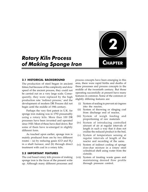
2.1 HISTORICAL BACKGROUND<br />
The production <strong>of</strong> steel began in ancient<br />
times; but because <strong>of</strong> the complexity and slow<br />
speed <strong>of</strong> the ancient process, they could not<br />
be carried out on a very large scale. Consequently,<br />
they were replaced by the high<br />
production rate ‘indirect process,’ and the<br />
development <strong>of</strong> modern DR <strong>Process</strong> did not<br />
begin until the middle <strong>of</strong> 19th century.<br />
Perhaps the very first patent in U.K. for<br />
sponge iron making was in 1792 presumably<br />
using a rotary kiln. More than 100 DR<br />
processes have been invented and operated<br />
since 1920. Most <strong>of</strong> these have died down. But<br />
some <strong>of</strong> them have re-emerged in slightly<br />
different form.<br />
As touched upon earlier, sponge iron is<br />
mainly produced from ore by two different<br />
routes – (a) by reducing gases (CO and H ) 2<br />
in a shaft furnace, and (b) through direct<br />
treatment with coal in a rotary kiln.<br />
2.2 IMPORTANT FEATURES<br />
The coal based rotary kiln process <strong>of</strong> making<br />
sponge iron is the focus <strong>of</strong> the present write<br />
up. Although many different processes and<br />
2<br />
CHAPTER<br />
process concepts have been emerging in this<br />
area, there were rapid births and deaths <strong>of</strong><br />
these processes and process concepts in the<br />
middle <strong>of</strong> the twentieth century. But those<br />
operating successfully at present have many<br />
features in common. Some <strong>of</strong> the common or<br />
slightly differing features are:<br />
(i) System <strong>of</strong> sealing to prevent air ingress<br />
into the reactor,<br />
(ii) System <strong>of</strong> throwing or slinging coal<br />
from discharge end <strong>of</strong> reactor,<br />
(iii) System <strong>of</strong> weigh feeding and<br />
proportioning <strong>of</strong> raw materials<br />
(iv) System <strong>of</strong> introducing controlled<br />
amount <strong>of</strong> air at regular intervals <strong>of</strong><br />
length in such a way that it does not<br />
oxidise the reduced product in the bed,<br />
(v) System <strong>of</strong> temperature sensing at<br />
regular intervals <strong>of</strong> length <strong>of</strong> the<br />
reactor and recording <strong>of</strong> the same.<br />
(vi) System <strong>of</strong> indirect cooling <strong>of</strong> sponge<br />
iron-char mixture in a rotary steel<br />
cylindrical shell using water from the<br />
outside.<br />
(vii) System <strong>of</strong> treating waste gases and<br />
maintaining desired flow pr<strong>of</strong>ile<br />
through pressure control.
10 // Advances in <strong>Rotary</strong> <strong>Kiln</strong> <strong>Sponge</strong> <strong>Iron</strong> Plant<br />
Fig. 2.1 Key steps in sponge iron<br />
making in rotary kiln<br />
Air<br />
blower<br />
Total time <strong>of</strong> materials in the rotary kiln<br />
(Residence time)<br />
Stack<br />
ID fan<br />
Fine<br />
coal<br />
Water spray<br />
Product<br />
Cooler<br />
Magnetic separator<br />
Dry ESP/<br />
bag filter<br />
Shell-mounted<br />
air fans<br />
Dust<br />
Ash<br />
Reduction kiln<br />
A typical process scheme for making<br />
sponge iron in a rotary kiln is presented in<br />
Fig. 2.1. While Fig. 2.1 shows only the key<br />
steps, a more detailed scheme, as it would<br />
appear for a typical operating plant, is<br />
presented in Fig. 2.2.<br />
2.3 SPONGE IRON PILOT PLANT OF<br />
RDCIS SAIL<br />
The sponge iron Pilot Plant (SIPP) <strong>of</strong> RDCIS,<br />
SAIL, which would be mentioned a number<br />
<strong>of</strong> times, was set up in 1980-82 with almost<br />
all the features <strong>of</strong> a commercial rotary kiln<br />
sponge iron plant. The know-how status<br />
was, however, slightly different at that<br />
time. Figure 2.3 represents more appropriately<br />
the SIPP <strong>of</strong> RDCIS SAIL.<br />
<strong>Iron</strong> ore<br />
coal<br />
flux<br />
Inlet hood<br />
Waste gas<br />
Fig. 2.2 A concise schematic representation <strong>of</strong> a rotary kiln sponge iron plant<br />
Dust<br />
Dust<br />
After<br />
burning &<br />
cooling<br />
chamber
1<br />
1 1 1 1 Waste gas<br />
2<br />
1. Raw material bins<br />
2. Belt conveyor<br />
3. Bucket elevator<br />
Air<br />
12<br />
Water<br />
13<br />
4. Surge bin<br />
5. Vibratory screen<br />
6. Magnetic separator<br />
<strong>Rotary</strong> <strong>Kiln</strong> <strong>Process</strong> <strong>of</strong> <strong>Making</strong> <strong>Sponge</strong> <strong>Iron</strong> // 11<br />
3<br />
7. Product storage bins<br />
8. After burning chamber<br />
9. Radial flow scrubber<br />
4<br />
6<br />
5<br />
6<br />
][ ][ ][<br />
7 7 7 7 7<br />
6<br />
10. Induced draught fan<br />
11. Waste gas stack<br />
12. <strong>Rotary</strong> kiln<br />
Fig. 2.3 A schematic <strong>of</strong> the sponge iron Pilot Plant <strong>of</strong> RDCIS, SAIL<br />
This Plant <strong>of</strong> capacity 5 to 9 tonnes per<br />
day <strong>of</strong> sponge iron was commissioned in<br />
March 1982 within the premises <strong>of</strong> M/s HEC<br />
at Ranchi, with the objective <strong>of</strong> adapting and<br />
assimilating coal based sponge iron<br />
technology in India. The Pilot Plant was in<br />
regular operation since its commissioning till<br />
1992-93, with 4 to 5 Campaigns each year.<br />
48 campaigns were carried out in the<br />
Pilot Plant with various ore and coal<br />
combinations from different deposits in the<br />
country. The two longest campaigns lasted<br />
62 days each. A total <strong>of</strong> 26 ore-coal<br />
combinations were processed in the Pilot<br />
Plant. Most <strong>of</strong> the iron ores tested in Pilot<br />
Plant were found suitable for sponge iron<br />
Fine coal<br />
<strong>Sponge</strong><br />
iron<br />
Char<br />
Air<br />
Air<br />
8<br />
9<br />
10<br />
11<br />
13. Cooler<br />
making. When operated with a good quality<br />
coal, metallisation level was consistently<br />
above 90%. On the other hand three <strong>of</strong> the<br />
coals tested in Pilot Plant were either not<br />
suitable or were only marginally acceptable.<br />
In such cases obviously metallisation levels<br />
were reduced – in extreme cases upto 70%.<br />
Other major results include:<br />
• Development <strong>of</strong> ore-coal composite<br />
pellets technology, which improves<br />
kiln productivity and reduces energy<br />
consumption (patented)<br />
• Pre-heating system <strong>of</strong> ore (patented)<br />
• Simultaneous injection <strong>of</strong> under-bed<br />
hydrocarbon fuel and over-bed air in a<br />
rotary reactor<br />
tubes<br />
<strong>Rotary</strong> kiln<br />
Thermocouples<br />
Waste gas<br />
<strong>Iron</strong> ore<br />
Fig. 2.4 Essential features <strong>of</strong> a reduction kiln in a rotary kiln sponge iron plant<br />
Coal<br />
Flux
12 // Advances in <strong>Rotary</strong> <strong>Kiln</strong> <strong>Sponge</strong> <strong>Iron</strong> Plant<br />
Fig. 2.5 Material balance in a rotary kiln sponge iron plant<br />
2.4 FEATURES OF A ROTARY KILN<br />
SPONGE IRON PLANT<br />
Figure 2.4 indicates the essential features<br />
which are needed in the reduction kiln <strong>of</strong> a<br />
sponge iron rotary kiln plant. However, the<br />
air tubes indicated in this diagram can be<br />
substituted by a ported kiln design, which is<br />
discussed later in this book.<br />
A typical material balance for the sponge<br />
iron making process is presented in Fig. 2.5.<br />
Here coal is assumed to contain about 20%<br />
ash, something which is hardly available now<br />
a days. Product is shown to be screened into<br />
three fractions. But due to difficulty in<br />
screening the -1 mm fraction, it is usual now<br />
a days not to separate out this fraction. Use<br />
<strong>of</strong> 6 to 20 mm iron ore is indicated. Presently<br />
it is more common to use 5 to 18 mm fraction.<br />
A typical energy balance in the form <strong>of</strong><br />
Sankey diagram is presented in Fig. 2.6.<br />
<strong>Rotary</strong> kiln processes have had to<br />
compete with gas-based processes. Gas<br />
based processes use relatively costlier<br />
input such as pellets and reformed natural<br />
gas and conversion cost at similar capacities<br />
are higher. But even then, gas-based<br />
processes have generally found favour due<br />
to better and more consistent quality,<br />
lower energy consumption and higher<br />
module size. It was realised early that<br />
rotary kiln processes can be up-scaled only<br />
to a limited extent and bigger module size<br />
does not mean a higher economy <strong>of</strong> scale.<br />
Modules bigger than 500 tpd were<br />
continuously plagued by problems <strong>of</strong><br />
accretion formation and were maintenance<br />
prone. All such modules have now been<br />
phased out.<br />
India has been the largest producer <strong>of</strong><br />
sponge iron since last few years. Its<br />
contribution to world DRI production is in<br />
excess <strong>of</strong> 25% at present. India has been<br />
increasing the gap with the next country<br />
Venezuela. Trends indicate that this gap<br />
would continue to increase in the foreseeable<br />
future. Iran is third on the line and Mexico,<br />
who was once the world leader, is presently<br />
placed fourth. One thing may be noted though
1.15, Char<br />
(Chemical<br />
energy)*<br />
0.3, Cooling<br />
losses<br />
(Sensible heat in<br />
solid product)<br />
9<br />
Unit GCal =<br />
10 calories<br />
that the entire production by number 2, 3 and<br />
4 countries is through gas based route while<br />
in India, more than half the production is by<br />
the coal based route.<br />
Input energy<br />
6.0, coal<br />
1.7<br />
<strong>Sponge</strong><br />
iron<br />
(Chemical<br />
energy)<br />
2.5 THE INDIAN SCENE<br />
Situation in India is different from the rest <strong>of</strong><br />
the world. Local conditions here have<br />
favoured coal based rotary kiln units and<br />
presently India has more such modules than<br />
rest <strong>of</strong> the world put together. Over 300<br />
modules are presently in production in India.<br />
And there is another trend in India <strong>of</strong><br />
downscaling. Only in India it has been found<br />
pr<strong>of</strong>itable to operate 100 tpd and 50 tpd<br />
module (even 25 tpd modules), while elsewhere<br />
250 tpd module is considered as the<br />
minimum economic size. Table 2.1 and Fig. 2.7<br />
present the production figures <strong>of</strong> sponge iron<br />
in India vis-à-vis world, over the years.<br />
<strong>Rotary</strong> <strong>Kiln</strong> <strong>Process</strong> <strong>of</strong> <strong>Making</strong> <strong>Sponge</strong> <strong>Iron</strong> // 13<br />
Fig. 2.6 Energy balance in a conventional rotary kiln sponge iron plant<br />
60<br />
50<br />
40<br />
30<br />
20<br />
20<br />
2.25,<br />
Waste<br />
gases<br />
(Chemical<br />
energy +<br />
Sensible heat)<br />
0.6, Radiative &<br />
Unaccounted losses<br />
coal and gas based processes.<br />
World DRI<br />
production<br />
DRI<br />
Production<br />
in India<br />
India’s<br />
share, %<br />
30%<br />
20%<br />
10%<br />
DRI production million tonnes Figure 2.8 presents the scene with respect to<br />
0<br />
0%<br />
1965 1970 1975 1980 1985 1990 1995 2000 2005 2010<br />
Year<br />
Fig. 2.7 A comparison <strong>of</strong> sponge iron<br />
production <strong>of</strong> India and World over the years<br />
Share <strong>of</strong> India's production
14 // Advances in <strong>Rotary</strong> <strong>Kiln</strong> <strong>Sponge</strong> <strong>Iron</strong> Plant<br />
<strong>Sponge</strong> iron production in the year 2006,<br />
million tonnes<br />
60.00 –<br />
50.00 –<br />
40.00 –<br />
30.00 –<br />
20.00 –<br />
10.00 –<br />
0.00 –<br />
Total<br />
15.00<br />
59.80<br />
Fig. 2.8 Another comparison <strong>of</strong> sponge iron production <strong>of</strong> India and World indicating<br />
the dominant position <strong>of</strong> coal based route in India<br />
The Krupp-Renn process, about which<br />
we mentioned in chapter 1, was probably<br />
the last <strong>of</strong> the rotary kiln processes, which<br />
attempted to produce iron in fused or<br />
semi-fused mass. All <strong>of</strong> the current<br />
processes attempt to prevent any type <strong>of</strong><br />
fusion during production.<br />
The processes, which are currently in<br />
vogue, are Jindal <strong>Process</strong> (50, 350 and 500 tpd),<br />
SIIL <strong>Process</strong> (100 tpd), OSIL <strong>Process</strong> (300 and<br />
500 tpd), SL/RN (Lurgi) <strong>Process</strong> (100 and 500<br />
tpd), Krupp-Codir <strong>Process</strong> (400 and 500 tpd),<br />
DRC <strong>Process</strong> (250 to 350 tpd) and TDR <strong>Process</strong><br />
(400 tpd). OSIL <strong>Process</strong> has evolved from the<br />
ported kiln concept <strong>of</strong> ACCAR <strong>Process</strong>, while<br />
SIIL <strong>Process</strong> has been based on the Lurgi or<br />
SL/RN <strong>Process</strong>. Presently, <strong>of</strong> the total sponge<br />
iron produced in the world, coal based rotary<br />
kiln processes contribute only about 15%, but<br />
considering India alone this percentage is<br />
about 65%. Trends point to substantial increase<br />
9.50<br />
10.70<br />
Coal based Gas based<br />
5.50<br />
49.10<br />
India<br />
World<br />
India<br />
World<br />
in the latter, in spite <strong>of</strong> the fact that a 2 mtpa<br />
gas based module has been commissioned<br />
recently in western India.<br />
As mentioned earlier, nearly 35% <strong>of</strong><br />
India’s sponge iron production is accounted<br />
for by the three gas based plants located near<br />
the western coast. M/s Essar Steel Limited<br />
located in Hazira in the state <strong>of</strong> Gujarat has<br />
five operating modules with a total capacity<br />
<strong>of</strong> 5.5 mtpy and claim to be the largest sponge<br />
iron plant in the world. Ispat Industries<br />
Limited and Vikram Ispat Limited both<br />
located in the state <strong>of</strong> Maharashtra have one<br />
module each <strong>of</strong> capacities 1.4 and 0.9 mtpy.<br />
On the coal based front, the plant <strong>of</strong> M/s<br />
Jindal Steel and Power Limited (JSPL) in<br />
Raigarh in the central Indian state <strong>of</strong><br />
Chhattisgarh is the largest in India and<br />
probably in the world. It has ten modules<br />
totalling 1.2 mtpy capacity.
Table 2.1 DRI Production: India and World*<br />
Million Tonnes<br />
Year India World<br />
1970 0 0.79<br />
1975 0 2.81<br />
1978 0 5.00<br />
1979 0 6.64<br />
1980 0.01 7.14<br />
1981 0.02 7.92<br />
1982 0.03 7.28<br />
1983 0.04 7.90<br />
1984 0.08 9.34<br />
1985 0.09 11.17<br />
1986 0.17 12.53<br />
1987 0.19 13.52<br />
1988 0.19 14.09<br />
1989 0.26 15.63<br />
1990 0.61 17.68<br />
1991 1.15 19.32<br />
1992 1.44 20.51<br />
1993 2.21 23.65<br />
1994 3.12 27.37<br />
1995 4.28 30.67<br />
1996 4.84 33.30<br />
1997 5.26 36.19<br />
1998 5.26 36.96<br />
1999 5.22 38.59<br />
2000 5.44 43.78<br />
2001 5.59 40.51<br />
2002 6.59 45.10<br />
2003 7.67 49.45<br />
2004 9.37 54.60<br />
2005 11.10 55.96<br />
2006 15.00 59.80<br />
*Data taken mainly direct from Midrex<br />
<strong>Rotary</strong> <strong>Kiln</strong> <strong>Process</strong> <strong>of</strong> <strong>Making</strong> <strong>Sponge</strong> <strong>Iron</strong> // 15<br />
Thus we see that the largest coal based<br />
plant in the world barely stands up to the<br />
smallest gas based module in India. But then<br />
the coal based plants make it up in numbers.<br />
As mentioned earlier, over 300 modules <strong>of</strong><br />
coal based plants are operating in India. And<br />
situation is changing so fast, almost on daily<br />
basis, that not much point is served by<br />
describing these plants here.<br />
Apart from JSPL, some <strong>of</strong> the plants<br />
which operate large size modules (300 to 500<br />
tpd) are Bihar <strong>Sponge</strong> <strong>Iron</strong> in Jharkhand,<br />
Prakash Industries, Nova <strong>Iron</strong> and Steel,<br />
Monnet Ispat, Godavari Ispat and Power all<br />
in Chhattisgarh, Sunflag <strong>Iron</strong> and Steel<br />
Company, Lloyds Metals and Engineers, in<br />
Maharashtra, Orissa <strong>Sponge</strong> <strong>Iron</strong>, Tata<br />
<strong>Sponge</strong> <strong>Iron</strong>, in Orissa, GSAL India in Andhra<br />
Pradesh, etc. We must make special mention<br />
<strong>of</strong> <strong>Sponge</strong> <strong>Iron</strong> India Limited in Paloncha in<br />
Andhra Pradesh, which was the first <strong>of</strong> the<br />
commercial plants (originally called a<br />
demonstration plant) commissioned in 1980,<br />
and which started the race for the installation<br />
<strong>of</strong> the 100 tpd modules, the total number now<br />
being well over one hundred. 50 tpd modules<br />
could also have exceeded 100 in number. But<br />
another special mention must be made <strong>of</strong> the<br />
25 tpd modules. One is operating in Ramgarh<br />
in Jharkhand (Palash <strong>Sponge</strong> <strong>Iron</strong>), while at<br />
least two modules are operating in Raipur in<br />
Chhattisgarh.<br />
2.6 WHY SHOULD WE SELECT A<br />
ROTARY KILN?<br />
The rotary kiln direct reduction (RKDR)<br />
processes have been looked upon with<br />
apprehension, mainly because there have been<br />
rapid births and deaths <strong>of</strong> processes in this<br />
group. But the fact that it has re-emerged,
16 // Advances in <strong>Rotary</strong> <strong>Kiln</strong> <strong>Sponge</strong> <strong>Iron</strong> Plant<br />
CO+CO 2 +H +H O+N<br />
2 2 2<br />
CO+½O=CO 2<br />
[Partial]<br />
Fig. 2.9 Delicate balance <strong>of</strong> oxidising and reducing conditions in a<br />
sponge iron rotary kiln<br />
points to certain strengths <strong>of</strong> this process. Let<br />
us examine some <strong>of</strong> them.<br />
2.6.1 <strong>Process</strong> Strengths<br />
<strong>Rotary</strong> kiln process has to compete mainly<br />
with the shaft process <strong>of</strong> making sponge iron<br />
and in some cases with iron making blast<br />
furnace. As compared to them, the rotary kiln<br />
has some advantages, as also some limitations,<br />
both with respect to the process and the<br />
product it makes. The major process<br />
strengths <strong>of</strong> rotary kiln are:<br />
(i) A rotary kiln can mix the solid charge<br />
as it heats and reduces it. Simultaneous<br />
mixing helps in the dilution <strong>of</strong> CO2 concentration formed around the iron<br />
ore/sponge iron particles – which is<br />
necessary for the reduction reaction<br />
to proceed.<br />
Air (4N 2+O 2)<br />
introduced<br />
through air tubes<br />
FeO+CO Fe+CO2 ↑<br />
CO 2+C = CO + CO2<br />
(ii) As a large freeboard volume is<br />
available above the solid charge (about<br />
85%), the rotary kiln can tolerate<br />
heavily dust-laden gas. When the kiln<br />
is suitably designed, it would be best<br />
suited for utilising the Indian high ash<br />
non-cooking coals. In shaft reactors,<br />
generation <strong>of</strong> such dust leads to<br />
choking and channelling which leads<br />
finally to disruption <strong>of</strong> the process.<br />
(iii) <strong>Rotary</strong> kiln can serve the dual purpose<br />
<strong>of</strong> a coal gasifier as well as an ore<br />
reducer. Preparation <strong>of</strong> reducing gas<br />
from coal is an expensive step, which<br />
is coming in the way <strong>of</strong> commercialisation<br />
<strong>of</strong> coal gasification based<br />
DR process. Therefore, rotary kiln DR<br />
process has proved commercially<br />
viable, even with low productivity per
unit volume, because <strong>of</strong> this capability<br />
to perform two different functions<br />
simultaneously.<br />
Figure 2.9 schematically represents the<br />
situation inside a rotary kiln where a delicate<br />
balance <strong>of</strong> reducing zone within the<br />
chargebed and an oxidising zone in the<br />
freeboard is always maintained.<br />
(iv) In comparison to blast furnace, the<br />
temperature <strong>of</strong> reduction <strong>of</strong> iron oxide<br />
is much lower in rotary kiln (about<br />
1000 o C as against 1500 to 2000 o C in blast<br />
furnace). This means that much less<br />
energy is required for bringing the<br />
reactants to the temperature <strong>of</strong> reaction.<br />
2.6.2 Product Strengths<br />
Additionally the strengths <strong>of</strong> the product<br />
made by rotary kiln are:<br />
(i) It is easy to desulphurise iron ore while<br />
making sponge iron. Consequently the<br />
sponge iron <strong>of</strong> much lower sulphur<br />
content can be produced as compared<br />
to blast furnace hot metal. For shaft<br />
process <strong>of</strong> sponge iron making, prior<br />
and meticulous de-sulphurisation <strong>of</strong><br />
natural gas is necessary to prevent<br />
poisoning <strong>of</strong> catalyst used for<br />
reforming.<br />
(ii) <strong>Sponge</strong> iron produced from rotary kiln<br />
is obtained in close granular size<br />
range. This permits charging in electric<br />
or other steel making furnaces in a<br />
continuous manner, obviating the need<br />
for opening and closing <strong>of</strong> ro<strong>of</strong>.<br />
Continuous charging permits partial<br />
refining during melting stage as the<br />
particle passes through the slag layer<br />
into the mixed layer. If adequate<br />
melting energy is available, refining<br />
time, and consequently, operation time<br />
can be considerably reduced.<br />
<strong>Rotary</strong> <strong>Kiln</strong> <strong>Process</strong> <strong>of</strong> <strong>Making</strong> <strong>Sponge</strong> <strong>Iron</strong> // 17<br />
2.6.3 Weaknesses <strong>of</strong> the <strong>Process</strong><br />
Notwithstanding the above, rotary kiln has<br />
a number <strong>of</strong> weaknesses. These are coming<br />
in the way <strong>of</strong> its wide acceptability. The main<br />
process related weaknesses <strong>of</strong> rotary kiln are:<br />
(i) It has very low productivity. Shaft<br />
furnaces, which make sponge iron,<br />
give upto five times more output than<br />
rotary kilns <strong>of</strong> same inner volume.<br />
Productivity in rotary kiln is<br />
consequently much lower.<br />
(ii) The rotating reactor makes it difficult<br />
to incorporate process control and<br />
quality control systems. Energy saving<br />
measures, such as use <strong>of</strong> pre-heated<br />
air, are difficult to incorporate. To<br />
prevent ingress <strong>of</strong> atmospheric air an<br />
elaborate sealing system is required,<br />
which has made the reactor very<br />
“engineering intensive”.<br />
(iii) The RKDR process has low energy<br />
efficiency. The stored energy in<br />
sponge iron is about 1.7 GCal per<br />
tonne, while energy usually spent in<br />
making it in rotary kiln is about 6<br />
GCal per tonne. Among other things,<br />
a lot <strong>of</strong> energy goes out in waste gases<br />
(over 2 GCal per tonne).<br />
(iv) The RKDR process produces some<br />
sponge iron in fine form (-3 mm) which<br />
is a little difficult to utilise in electric<br />
furnaces. While much <strong>of</strong> the fines are<br />
generated due to the nature <strong>of</strong> ore<br />
used, the situation is aggravated by<br />
the tumcbling action within the rotary<br />
kiln, which forces s<strong>of</strong>ter particles to<br />
break down further.<br />
2.6.4 Weaknesses <strong>of</strong> the Product<br />
In addition the sponge iron made by rotary<br />
kiln has the following weaknesses:
18 // Advances in <strong>Rotary</strong> <strong>Kiln</strong> <strong>Sponge</strong> <strong>Iron</strong> Plant<br />
(i) For charging in electric furnaces in<br />
substantial quantities, a system <strong>of</strong><br />
continuous charging needs to be<br />
installed. This would mean an<br />
additional investment for the existing<br />
units, which are not having this<br />
facility.<br />
(ii) The sponge iron from rotary kiln has<br />
much lower carbon content (usually<br />
0.2%) than either the sponge iron from<br />
shaft furnace (0.7 to 2%) or the hot<br />
metal from blast furnace. Carbon in<br />
sponge iron not only helps in adding to<br />
the opening carbon in molten bath, it<br />
also carries in chemical energy, which<br />
helps in reducing the consumption <strong>of</strong><br />
electric power. Too low a carbon content<br />
comes in the way <strong>of</strong> a healthy carbon<br />
boil and, therefore, bath carburisers<br />
need to be added. Clean carburisers are<br />
costly while coke, char or pig iron carries<br />
with it undesirable elements like sulphur<br />
and phosphorous.<br />
(iii) <strong>Sponge</strong> iron from rotary kiln carries<br />
with it more gangue and phosphorous<br />
than those from shaft furnace, mainly<br />
because shaft furnace uses cleaner<br />
inputs. Gangue and phosphorous<br />
contents are much higher than they<br />
are in iron and steel scrap, which means<br />
extra inputs <strong>of</strong> phosphorous and slag<br />
in electric furnaces.<br />
(iv) When we compare with scrap and pig<br />
iron, all sponge irons are prone to reoxidation<br />
and the product from rotary<br />
kiln is no exception. However, this<br />
rotary kiln sponge iron is much less<br />
susceptible to re-oxidation as<br />
compared to sponge iron from shaft<br />
units using reformed gases.<br />
Those who have ventured into sponge<br />
iron have to endeavour to exploit the<br />
strengths <strong>of</strong> RKDR to the fullest extent and<br />
would have to try to mitigate the effects <strong>of</strong><br />
its weaknesses suitably. Those who<br />
contemplate venturing into sponge iron have<br />
to make a thorough analysis as to whether<br />
the strengths outweigh the disadvantages or<br />
not in the scenario they are finding themselves<br />
in. It becomes the duty <strong>of</strong> the process<br />
developers to put in innovations, which make<br />
greater use <strong>of</strong> the strengths and minimise to<br />
the extent possible the weaknesses <strong>of</strong> RKDR.<br />
There are many basic aspects, which need<br />
to be considered for making sponge iron in<br />
rotary kiln, the important ones being:<br />
(i) Thermodynamics <strong>of</strong> reduction and<br />
gasification reactions<br />
(ii) Characteristics <strong>of</strong> raw materials and<br />
their role in the process<br />
(iii) Reaction kinetics, roles <strong>of</strong> reducibility<br />
<strong>of</strong> iron ore and reactivity <strong>of</strong> coal char<br />
and thereby the basis <strong>of</strong> selection <strong>of</strong><br />
iron ore and coal<br />
(iv) Movement <strong>of</strong> solids in the rotary kiln<br />
and its residence time<br />
(v) Gas evolution and flow rate<br />
(vi) Heat transfer, temperature pr<strong>of</strong>ile and<br />
process model<br />
These would be dealt in the subsequent<br />
chapters.