manual (68 KB) - Phywe
manual (68 KB) - Phywe
manual (68 KB) - Phywe

Create successful ePaper yourself
Turn your PDF publications into a flip-book with our unique Google optimized e-Paper software.
R<br />
Operating Instructions<br />
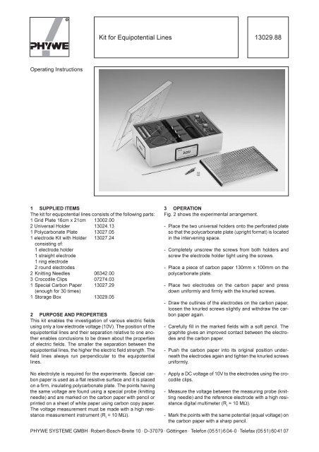
Kit for Equipotential Lines<br />
1 SUPPLIED ITEMS<br />
The kit for equipotential lines consists of the following parts:<br />
1 Grid Plate 16cm x 21cm 13002.00<br />
2 Universal Holder 13024.13<br />
1 Polycarbonate Plate 13027.05<br />
1 electrode Kit with Holder 13027.24<br />
consisting of:<br />
1 electrode holder<br />
1 straight electrode<br />
1 ring electrode<br />
2 round electrodes<br />
2 Knitting Needles 06342.00<br />
3 Crocodile Clips 07274.03<br />
1 Special Carbon Paper 13027.29<br />
(enough for 30 times)<br />
1 Storage Box 13029.05<br />
2 PURPOSE AND PROPERTIES<br />
This kit enables the investigation of various electric fields<br />
using only a low electrode voltage (10V). The position of the<br />
equipotential lines and their separation relative to one another<br />
enables conclusions to be drawn about the properties<br />
of electric fields. The smaller the separation between the<br />
equipotential lines, the higher the electric field strength. The<br />
field lines always run perpendicular to the equipotential<br />
lines.<br />
No electrolyte is required for the experiments. Special carbon<br />
paper is used as a flat resistive surface and it is placed<br />
on a firm, insulating polycarbonate plate. The points having<br />
the same voltage are found using a special probe (knitting<br />
needle) and are marked on the carbon paper with pencil or<br />
printed on a sheet of white paper using carbon copy paper.<br />
The voltage measurement must be made with a high resistance<br />
measurement instrument (R i = 10 MΩ).<br />
3 OPERATION<br />
Fig. 2 shows the experimental arrangement.<br />
13029.88<br />
- Place the two universal holders onto the perforated plate<br />
so that the polycarbonate plate (upright format) is located<br />
in the intervening space.<br />
- Completely unscrew the screws from both holders and<br />
screw the electrode holder tight using the screws.<br />
- Place a piece of carbon paper 130mm x 100mm on the<br />
polycarbonate plate.<br />
- Place two electrodes on the carbon paper and press<br />
down uniformly and firmly with the knurled screws.<br />
- Draw the outlines of the electrodes on the carbon paper,<br />
loosen the knurled screws slightly and withdraw the carbon<br />
paper again.<br />
- Carefully fill in the marked fields with a soft pencil. The<br />
graphite gives an improved contact between the electrodes<br />
and the carbon paper.<br />
- Push the carbon paper into its original position underneath<br />
the electrodes again and tighten the knurled screws<br />
uniformly.<br />
- Apply a DC voltage of 10V to the electrodes using the crocodile<br />
clips.<br />
- Measure the voltage between the measuring probe (knitting<br />
needle) and the reference electrode with a high resistance<br />
digital multimeter (R i = 10 MΩ).<br />
- Mark the points with the same potential (equal voltage) on<br />
the carbon paper with a sharp pencil.<br />
PHYWE SYSTEME GMBH · Robert-Bosch-Breite 10 · D-37079 · Göttingen · Telefon (05 51) 6 04-0 ·Telefax (05 51) 60 41 07
Fig. 2: Experimental arrangement for the measurement of equipotential lines<br />
3.1: Homogeneous field between<br />
straight electrodes (plate capacitor)<br />
3.2: Radial field between round<br />
and ring electrodes (coaxial<br />
cable)<br />
Fig. 3: Equipotential lines and field lines of various field<br />
- Loosen the electrodes and withdraw the carbon paper.<br />
- Join the points having the same potential with lines (equipotential<br />
lines).<br />
- Draw lines at a uniform distance, perpendicular to all equipotential<br />
lines (field lines).<br />
Note:<br />
1. If the fields that have been measured are unsymmetrical,<br />
then the contact between the electrodes and the carbon<br />
paper should be checked. Press the electrodes<br />
down more firmly or use a softer pencil for the contact<br />
surfaces.<br />
2. If carbon copy paper and white paper are placed between<br />
the carbon paper and the polycarbonate plate, the<br />
measuring points can be pressed onto the white paper<br />
with the knitting needle. The carbon paper can be reused<br />
a number of times.<br />
3.3: Field between round and straight electrodes<br />
(point charge and conducting<br />
surface)<br />
2<br />
3.4: Field between two round electrodes<br />
(dipolar field)<br />
4 MATERIAL LIST<br />
Kit for Equipotential Lines 13029.88<br />
Power Supply 0...12VDC/2A, 6VAC, 12VAC/5A 13505.93<br />
Digital Multimeter 07134.00<br />
Connecting leads (4x)<br />
Consumable material:<br />
Special Carbon Paper 13027.29<br />
13029.88