Minimum Standard 3.13 - Grassed Swale - Virginia Department of ...
Minimum Standard 3.13 - Grassed Swale - Virginia Department of ...
Minimum Standard 3.13 - Grassed Swale - Virginia Department of ...

Create successful ePaper yourself
Turn your PDF publications into a flip-book with our unique Google optimized e-Paper software.
MINIMUM STANDARD <strong>3.13</strong> CHAPTER 3<br />
MINIMUM STANDARD <strong>3.13</strong><br />
GRASSED SWALE
MINIMUM STANDARD <strong>3.13</strong> CHAPTER 3
MINIMUM STANDARD <strong>3.13</strong> CHAPTER 3<br />
LIST OF ILLUSTRATIONS<br />
# FIGURES PAGE<br />
<strong>3.13</strong>-1 Typical <strong>Grassed</strong> <strong>Swale</strong> Configuration ............................. <strong>3.13</strong>-2<br />
<strong>3.13</strong>-2 Typical Water Quality <strong>Swale</strong> Configuration ........................ <strong>3.13</strong>-3<br />
<strong>3.13</strong>-3 Typical Check Dam Configurations ............................. <strong>3.13</strong>-15<br />
<strong>3.13</strong>-4 Manning’s ‘n’ Values for Varying Depths <strong>of</strong> Flow.................. <strong>3.13</strong>-16<br />
# TABLES PAGE<br />
<strong>3.13</strong>-1 Pollutant Removal Efficiency for <strong>Grassed</strong> <strong>Swale</strong>s ................... <strong>3.13</strong>-4<br />
<strong>3.13</strong>-2 Stone or Riprap Sizes for Gabion Baskets......................... <strong>3.13</strong>-13
MINIMUM STANDARD <strong>3.13</strong> CHAPTER 3<br />
MINIMUM STANDARD <strong>3.13</strong><br />
GRASSED SWALE<br />
Definition<br />
A grassed swale is a broad and shallow earthen channel vegetated with erosion resistant and floodtolerant<br />
grasses. Check dams are strategically placed in the swale to encourage ponding behind<br />
them.<br />
A water quality swale is a broad and shallow earthen channel vegetated with erosion resistant and<br />
flood tolerant grasses, and underlain by an engineered soil mixture.<br />
Purpose<br />
The purpose <strong>of</strong> grassed swales and water quality swales is to convey stormwater run<strong>of</strong>f at a nonerosive<br />
velocity in order to enhance its water quality through infiltration, sedimentation, and<br />
filtration. Check dams are used within the swale to slow the flow rate and create small, temporary<br />
ponding areas. A water quality swale is appropriate where greater pollutant removal efficiency is<br />
desired.<br />
Water Quality Enhancement<br />
<strong>Grassed</strong> swalesand water quality swales remove pollution through sedimentation, infiltration, and<br />
filtration. Water quality swales are specifically engineered to filter stormwater through an<br />
underlying soil mixture while grasses swales are designed to slow the velocity <strong>of</strong> flow to encourage<br />
settling and filtering through the grass lining. Vegetation filters out the sediments and other<br />
particulate pollutants from the run<strong>of</strong>f and increases the opportunity for infiltration and adsorption<br />
<strong>of</strong> soluble pollutants. The flow rate becomes a critical design element, since run<strong>of</strong>f must pass<br />
through the vegetation slowly for pollutant removal to occur. Monitoring <strong>of</strong> grassed swales has<br />
indicated low to moderate removal <strong>of</strong> soluble pollutants (phosphorous and nitrogen) and moderate<br />
to high removal <strong>of</strong> particulate pollutants.<br />
Flood Control<br />
<strong>Grassed</strong> swales and water quality swales will usually provide some peak attenuation depending on<br />
the storage volume created by the check dams. However, flood control should be considered a<br />
secondary function <strong>of</strong> grassed swales since the required storage volume for flood control is usually<br />
more than they can provide.<br />
<strong>3.13</strong>-1
MINIMUM STANDARD <strong>3.13</strong> CHAPTER 3<br />
FIGURE <strong>3.13</strong> - 1<br />
Typical <strong>Grassed</strong> <strong>Swale</strong> Configuration<br />
<strong>3.13</strong>-2
MINIMUM STANDARD <strong>3.13</strong> CHAPTER 3<br />
FIGURE <strong>3.13</strong> - 2<br />
Typical Water Quality <strong>Swale</strong> Configuration<br />
<strong>3.13</strong>-3
MINIMUM STANDARD <strong>3.13</strong> CHAPTER 3<br />
Water Quality BMP<br />
TABLE <strong>3.13</strong> - 1<br />
Pollutant Removal Efficiency for <strong>Grassed</strong> <strong>Swale</strong>s<br />
Target Phosphorus<br />
Removal Efficiency<br />
Condition Where Practice Applies<br />
<strong>3.13</strong>-4<br />
Impervious Cover<br />
<strong>Grassed</strong> <strong>Swale</strong> 15% 16 - 21%<br />
Water Quality <strong>Swale</strong> 35% 16 - 37%<br />
Channel Erosion Control<br />
<strong>Grassed</strong> swales and water quality swales may also provide some benefits relative to channel erosion<br />
by reducing the peak rate <strong>of</strong> discharge from a drainage area. However, the holding capacity <strong>of</strong> a<br />
grassed swale designed for water quality purposes is limited.<br />
Drainage Area<br />
<strong>Grassed</strong> swales and water quality swales engineered for enhancing water quality cannot effectively<br />
convey large flows. Therefore, their contributing drainage areas must be kept small. The dimensions<br />
(length, width, and overall geometry) and slope <strong>of</strong> the swale, and its ability to convey the 10-year<br />
storm at a non-erosive velocity will set the size <strong>of</strong> the contributing drainage area.<br />
Development Conditions<br />
<strong>Grassed</strong> swales are commonly used instead <strong>of</strong> curb and gutter drainage systems in low- to moderatedensity<br />
(16 to 21% impervious) single-family residential developments. Since grassed swales do not<br />
function well with high volumes or velocities <strong>of</strong> stormwater, they have limited application in highly<br />
urbanized or other highly impervious areas. However, swales may be appropriate for use in these<br />
areas if they are constructed in series or as pretreatment facilities for other BMPs.<br />
<strong>Grassed</strong> swales are usually located within the right-<strong>of</strong>-way when used to receive run<strong>of</strong>f from<br />
subdivision or rural roadways. They may also be installed within drainage easements along the side<br />
or rear <strong>of</strong> residential lots. <strong>Grassed</strong> swales can be strategically located within the landscape to<br />
intercept run<strong>of</strong>f from small impervious surfaces (small parking lots, ro<strong>of</strong>tops, etc.) as a component<br />
<strong>of</strong> a subdivision-wide or development-wide BMP strategy.<br />
Water quality swales are appropriate for the same development conditions as those listed for grassed<br />
swales with the addition <strong>of</strong> higher densities <strong>of</strong> development (16 - 37% impervious) due to the<br />
increased pollutant removal capability.
MINIMUM STANDARD <strong>3.13</strong> CHAPTER 3<br />
Planning Considerations<br />
Figure <strong>3.13</strong>-1 pesents a grassed swale designed to hold small pockets <strong>of</strong> water behind each check<br />
dam. The water slowly drains through small openings in the chack dam and/or infiltrates into the<br />
ground. Slow channel velocities allow the vegetation to filter out sediments and other particulate<br />
pollutants from the run<strong>of</strong>f and increases the opportunity for infiltration and adsorption <strong>of</strong> soluble<br />
pollutants.<br />
Figure <strong>3.13</strong>-2 presents a water quality swale with an engineered soils media directly under the<br />
swale, with an underdrain. This design may be used in areas where the soils are not conducive to<br />
infiltration, or in developments where the swale is constructed beside a roadway using fill or<br />
compacted soils.<br />
Site Conditions<br />
The following items should be considered when selecting a grassed swale as a water quality BMP:<br />
1. Soils – <strong>Grassed</strong> swales can be used with soils having moderate infiltration rates <strong>of</strong> 0.27<br />
inches per hour (silt loam) or greater. Besides permeability, soils should support a good<br />
stand <strong>of</strong> vegetative cover with minimal fertilization.<br />
Water quality swales can be used in areas <strong>of</strong> unsuitable soil conditions for infiltration since<br />
the engineered soil mixture and underdrain system is used in place <strong>of</strong> the insitu soils.<br />
2. Topography – The topography <strong>of</strong> the site should be relatively flat so that the swale can be<br />
constructed with a slope and cross-section that maintains low velocities and creates adequate<br />
storage behind the check dams.<br />
3. Depth to water table – A shallow or seasonally-high groundwater table will inhibit the<br />
opportunity for infiltration. Therefore, the bottom <strong>of</strong> the swale should be at least 2 feet above<br />
the water table.<br />
Sediment Control<br />
<strong>Grassed</strong> swales may be used for conveyance <strong>of</strong> stormwater run<strong>of</strong>f during the construction phase <strong>of</strong><br />
development. However, the swales should be maintained as required by the <strong>Virginia</strong> Erosion and<br />
Sediment Control Regulations and local program requirements. Before final stabilization, sediment<br />
must be removed from the swales and the soil surface prepared for final stabilization. Tilling <strong>of</strong> the<br />
swale bottom may be needed to open the surface pores and re-establish the soil’s permeability.<br />
Water quality swales should be constructed after a majority <strong>of</strong> the drainage area has been stabilized.<br />
<strong>3.13</strong>-5
MINIMUM STANDARD <strong>3.13</strong> CHAPTER 3<br />
(Refer to Min. Std. 3.11: Bioretention Facilities).<br />
This section presents minimum criteria and recommendations for the design <strong>of</strong> grassed swales used<br />
to enhance water quality. It is the designer’s responsibility to decide which criteria are applicable<br />
to the particular swale being designed and to decide if any additional design elements are required.<br />
The designer must also provide for the long-term functioning <strong>of</strong> the facility by choosing appropriate<br />
structural materials.<br />
The design <strong>of</strong> a water quality grassed swale includes calculations for traditional swale parameters<br />
(flow rate, maximum permissible velocities, etc.) along with storage volume calculations for the<br />
water quality volume.<br />
Hydrology<br />
The hydrology <strong>of</strong> a grassed swale’s contributing drainage area should be developed per Chapter<br />
4, Hydrologic Methods.<br />
<strong>Swale</strong> Geometry<br />
A grassed swale should have a trapezoidal cross-section to spread flows across its flat bottom.<br />
Triangular or parabolic shaped sections will concentrate the run<strong>of</strong>f and should be avoided. The side<br />
slopes <strong>of</strong> the swale should be no steeper than 3H:1V to simplify maintenance and to help prevent<br />
erosion.<br />
Bottom Width<br />
The bottom width <strong>of</strong> the swale should be 2 feet minimum and 6 feet maximum in order to maintain<br />
sheet flow across the bottom and to avoid concentration <strong>of</strong> low flows. The actual design width <strong>of</strong><br />
the swale is determined by the maximum desirable flow depth, as discussed below.<br />
Flow Depth<br />
Design Criteria<br />
The flow depth for a water quality grassed swale should be approximately the same as the height <strong>of</strong><br />
the grass. An average grass height for most conditions is 4 inches. Therefore, the maximum flow<br />
depth for the water quality volume should be 4 inches (Center for Watershed Protection, 1996).<br />
<strong>3.13</strong>-6
MINIMUM STANDARD <strong>3.13</strong> CHAPTER 3<br />
Flow Velocity<br />
The maximum velocity <strong>of</strong> the water quality volume through the grassed swale should be no greater<br />
than 1.5 feet per second. The maximum design velocity <strong>of</strong> the larger storms should be kept low<br />
enough so as to avoid resuspension <strong>of</strong> deposited sediments. The 2-year storm recommended<br />
maximum design velocity is 4 feet per second and the 10-year storm recommended maximum design<br />
velocity is 7 feet per second.<br />
Longitudinal Slope<br />
The slope <strong>of</strong> the grassed swale should be as flat as possible, while maintaining positive drainage and<br />
uniform flow. The minimum constructable slope is between 0.75 and 1.0%. The maximum slope<br />
depends upon what is needed to maintain the desired flow velocities and to provide adequate storage<br />
for the water quality volume, while avoiding excessively deep water at the downstream end.<br />
Generally, a slope <strong>of</strong> between 1 and 3% is recommended. The slope should never exceed 5%.<br />
<strong>Swale</strong> length<br />
<strong>Swale</strong> length is dependent on the swale’s geometry and the ability to provide the required storage<br />
for the water quality volume.<br />
<strong>Swale</strong> Capacity<br />
The capacity <strong>of</strong> the grassed swale is a combined function <strong>of</strong> the flow volume (the water quality<br />
volume) and the physical properties <strong>of</strong> the swale such as longitudinal slope and bottom width. By<br />
using the Manning equation or channel flow nomographs, the depth <strong>of</strong> flow and velocity for any<br />
given set <strong>of</strong> values can be obtained. The Manning’s ‘n’ value, or roughness coefficient, varies with<br />
the depth <strong>of</strong> flow and vegetative cover. An ‘n’ value <strong>of</strong> 0.15 is appropriate for flow depths <strong>of</strong> up to<br />
4 inches (equal to the grass height). The n value decreases to a minimum <strong>of</strong> 0.03 for grass swales<br />
at a depth <strong>of</strong> approximately 12 inches.<br />
A grassed swale should have the capacity to convey the peak flows from the 10-year design storm<br />
without exceeding the maximum permissible velocities. (Note that a maximum velocity is specified<br />
for the 2-year and 10-year design storms to avoid resuspension <strong>of</strong> deposited sediments and other<br />
pollutants and to prevent scour <strong>of</strong> the channel bottom and side slopes.) The swale should pass the<br />
10-year flow over the top <strong>of</strong> the check dams with 6 inches, minimum, <strong>of</strong> freeboard. As an<br />
alternative, a bypass structure may be engineered to divert flows from the larger storm events (run<strong>of</strong>f<br />
greater than the water quality volume) around the grassed swale. However, when the additional area<br />
and associated costs for a bypass structure and conveyance system are considered, it may be more<br />
economical to simply increase the bottom width <strong>of</strong> the grassed swale. It should then be designed<br />
to carry run<strong>of</strong>f from the 10-year frequency design storm at the required permissible velocity.<br />
<strong>3.13</strong>-7
MINIMUM STANDARD <strong>3.13</strong> CHAPTER 3<br />
The longitudinal slope and the bottom width may be adjusted to achieve the maximum allowable<br />
velocity according to the Manning equation:<br />
Q ' 1.49<br />
n<br />
<strong>3.13</strong>-8<br />
r b s ½ A<br />
Equation <strong>3.13</strong>-1<br />
Manning Equation<br />
Where: Q = peak flow rate, cfs<br />
n = Manning’s roughness coefficient<br />
r = hydraulic radius, ft. = A / wp<br />
s = longitudinal slope <strong>of</strong> the channel<br />
A = cross-sectional area <strong>of</strong> the channel, ft 2<br />
The portion <strong>of</strong> the equation within the brackets represents the velocity <strong>of</strong> flow. Equation <strong>3.13</strong>-1 can<br />
be rewritten as:<br />
Where: Q = peak flow rate, cfs<br />
Q =VA<br />
Equation <strong>3.13</strong>-2<br />
Continuity Equation<br />
1.49<br />
n<br />
r b s ½<br />
V = flow velocity, ft/s =<br />
A = cross-sectional area <strong>of</strong> the channel, ft 2 .<br />
Additional guidance on the use <strong>of</strong> the Manning equation for the design <strong>of</strong> grassed swales is provided<br />
in the <strong>Virginia</strong> Erosion and Sediment Control Handbook (VESCH), 1992 edition.<br />
Water Quality Volume<br />
If a grassed swale is used as a conveyance channel, its purpose is to transport stormwater to the<br />
discharge point. However, the purpose <strong>of</strong> a water quality grassed swale is to slow the water as much<br />
as possible to encourage pollutant removal.<br />
The use <strong>of</strong> check dams will create segments <strong>of</strong> the swale which will be inundated for a period <strong>of</strong>
MINIMUM STANDARD <strong>3.13</strong> CHAPTER 3<br />
time. The required total storage volume behind the check dams is equal to the water quality volume<br />
for the contributing drainage area to that point. However, the maximum ponding depth behind the<br />
check dams should not exceed 18 inches. To insure that this practice does not create nuisance<br />
conditions, an analysis <strong>of</strong> the subsoil should be conducted to verify its permeability.<br />
Underlying Soil Bed - Water Quality <strong>Swale</strong>s<br />
An underlying engineered soil bed and underdrain system may be utilized in areas where the soils<br />
are not permeable and the swale would remain full <strong>of</strong> water for extended periods <strong>of</strong> time (creating<br />
nuisance conditions). This soil bed should consist <strong>of</strong> a moderately permeable soil material with a<br />
high level <strong>of</strong> organic matter: 50% sand, 20% leaf mulch, 30% top soil. The soil bed should be 30<br />
inches deep and should be accompanied by a perforated pipe and gravel underdrain system.<br />
In residential developments with marginal soils, it may be appropriate to provide a soil bed and<br />
underdrain system in all grassed swales to avoid possible safety and nuisance concerns.<br />
Check Dams<br />
The use <strong>of</strong> check dams in a grassed swale should be per the following criteria:<br />
1. Height – A maximum height <strong>of</strong> 18 inches is recommended, and the dam height should not<br />
exceed one-half the height <strong>of</strong> the swale bank.<br />
2. Spacing – Spacing should be such that the slope <strong>of</strong> the swale and the height <strong>of</strong> the check<br />
dams combine to provide the required water quality volume behind the dams.<br />
3. Abutments – Check dams should be anchored into the swale wall a minimum <strong>of</strong> 2 to 3 feet<br />
on each side.<br />
4. Toe Protection – The check dam toe should be protected with riprap placed over a suitable<br />
geotextile fabric. The size (D 50) <strong>of</strong> the riprap should be based on the design flow in the<br />
swale. Class A1 Riprap is recommended.<br />
5. Overflow – A notch should be placed in the top <strong>of</strong> the check dam to allow the 2-year peak<br />
discharge to pass without coming into contact with the check dam abutments, or the<br />
abutments may be protected with a non-erodible material. Six inches <strong>of</strong> freeboard should<br />
be provided between the 10-year overflow and the top <strong>of</strong> the swale.<br />
6. Riprap check dams – Rip rap check dams should consist <strong>of</strong> a VDOT No. 1 Open-graded<br />
Coarse Aggregate core keyed into the ground a minimum <strong>of</strong> 6 inches, with a Class A1 riprap<br />
shell.<br />
<strong>3.13</strong>-9
MINIMUM STANDARD <strong>3.13</strong> CHAPTER 3<br />
7. Filter fabric – Filter fabric is required under riprap and gabion check dams.<br />
8. Driveway culvert weirs – Where a driveway culvert is encountered, a ½ round corrugated<br />
metal pipe weir bolted to the concrete driveway headwall may be utilized as a check dam,<br />
or a timber check dam placed at least one foot upstream <strong>of</strong> the culvert opening.<br />
Outlets<br />
Discharges from grassed swales must be conveyed at non-erosive velocities to either a stream or a<br />
stabilized channel to prevent scour at the outlet <strong>of</strong> the swale. Refer to VESCH, 1992 edition for<br />
design procedures and specifications regarding outlet stabilization.<br />
Inflow Points<br />
<strong>Swale</strong> inflow points should be protected with erosion controls as needed (e.g., riprap, flow<br />
spreaders, energy dissipators, sediment forebays, etc.).<br />
Vegetation<br />
A dense cover <strong>of</strong> water-tolerant, erosion-resistant grass or other vegetation must be established.<br />
Grasses used in swales should have the following characteristics:<br />
C a deep root system to resist scouring,<br />
C a high stem density, with well-branched top growth,<br />
C tolerance to flooding,<br />
C resistance to being flattened by run<strong>of</strong>f, and<br />
C an ability to recover growth following inundation.<br />
Recommended grasses include, but are not limited to, the following: Kentucky-31 tall fescue, reed<br />
canary grass, redtop, and rough-stalked blue grass. Note that these grasses can be mixed.<br />
The selection <strong>of</strong> an appropriate vegetative lining for a grassed swale is based on several factors<br />
including climate, soils, and topography. For additional information, refer to STD. & SPEC. 3.32:<br />
Permanent Seeding in VESCH, 1992 edition.<br />
Erosion control matting should be used to stabilize the soil before seed germination. This protects<br />
the swale from erosion during the germination process. In most cases, the use <strong>of</strong> sod is warranted<br />
to provide immediate stabilization on the swale bottom and/or side slopes. Refer to STD. & SPEC.<br />
3.33: Sodding in VESCH, 1992 edition for additional information.<br />
<strong>3.13</strong>-10
MINIMUM STANDARD <strong>3.13</strong> CHAPTER 3<br />
Construction Specifications<br />
Overall, widely accepted construction standards and specifications, such as those developed by the<br />
USDA Soil Conservation Service or the U. S. Army Corps <strong>of</strong> Engineers, should be followed where<br />
applicable. Further guidance can be found in the SCS Engineering Field Manual. Specifications for<br />
the work should conform to the methods and procedures specified for earthwork, concrete,<br />
reinforcing steel, woodwork and masonry, as they apply to the site and the purpose <strong>of</strong> the structure.<br />
The specifications should also satisfy any requirements <strong>of</strong> the local government.<br />
Sequence <strong>of</strong> Construction<br />
The construction <strong>of</strong> grassed swales should be coordinated with the overall project construction<br />
schedule. The swale may be excavated during the rough grading phase <strong>of</strong> the project to permit use<br />
<strong>of</strong> the excavated material as fill in earthwork areas. Otherwise, grassed swales should not be<br />
constructed or placed into service until the entire contributing drainage area has been stabilized.<br />
Run<strong>of</strong>f from untreated, recently constructed areas may load the newly formed swale with a large<br />
volume <strong>of</strong> fine sediment. This could seriously impair the swale’s natural infiltration ability.<br />
The specifications for construction <strong>of</strong> a grassed swale should state the following:<br />
C the earliest point in progress when storm drainage may be directed to the swale, and<br />
C the means by which this delay in use will be accomplished.<br />
Due to the wide variety <strong>of</strong> conditions encountered among projects, each project should be evaluated<br />
separately evaluated to decide how long to delay use <strong>of</strong> the swale.<br />
Excavation<br />
Initially, the swale should be excavated to within one foot <strong>of</strong> its final elevation. Excavation to the<br />
finished grade should be deferred until all disturbed areas in the watershed have been stabilized or<br />
protected. The final phase <strong>of</strong> excavation should remove all accumulated sediment. When final<br />
grading is completed, the swale bottom should be tilled with rotary tillers or disc harrows to provide<br />
a well-aerated, highly porous surface texture.<br />
Vegetation<br />
Establishing dense vegetative cover on the swale side slopes and floor is required. This cover will<br />
not only prevent erosion and sloughing, but will also provide a natural means to maintain relatively<br />
high infiltration rates.<br />
<strong>3.13</strong>-11
MINIMUM STANDARD <strong>3.13</strong> CHAPTER 3<br />
Selection <strong>of</strong> suitable vegetative materials and application <strong>of</strong> required fertilizer and mulch should be<br />
per VESCH, 1992 edition.<br />
Materials<br />
1. Check dams – Check dams shall be constructed <strong>of</strong> a non-erosive material such as wood,<br />
gabions, riprap, or concrete. All check dams shall be underlaid by filter fabric per Std. &<br />
Spec 3.19: Rip Rap <strong>of</strong> VESCH, 1992 edition.<br />
a. Wood - pressure treated logs or timbers, or water-resistant tree species such as cedar,<br />
hemlock, swamp oak or locust.<br />
b. Gabions - hexagonal triple twist mesh with PVC coated galvanized steel wire. The<br />
maximum linear dimension <strong>of</strong> the mesh opening shall not exceed 4.5 inches. The<br />
area <strong>of</strong> the mesh opening shall not exceed 10 square inches.<br />
Stone or riprap for gabions shall be sized according to Table <strong>3.13</strong>-2. It shall consist <strong>of</strong> field<br />
stone or rough unhewn quarry stone. The stone shall be hard and angular and <strong>of</strong> a quality<br />
that will not disintegrate with exposure to water or weathering. The specific gravity <strong>of</strong> the<br />
individual stones shall be at least 2.5.<br />
Recycled concrete may be used if it has a density <strong>of</strong> at least 150 pounds per cubic foot and<br />
does not have any exposed steel or reinforcing bars.<br />
c. Riprap - all riprap shall conform with VESCH Std. & Spec 3.19: Riprap, and VDOT<br />
<strong>Standard</strong>s for open graded course aggregate.<br />
d. Concrete - All concrete shall conform with VDOT or SCS specifications.<br />
2. Underlying soil medium – The underlying soils should consist <strong>of</strong> the following:<br />
a. Soil - USDA ML, SM, or SC.<br />
b. Sand - ASTM C-33 fine aggregate concrete sand; VDOT fine aggreagate, grading<br />
A or B.<br />
3. Pea Gravel – Pea gravel should consist <strong>of</strong> washed ASTM M-43; VDOT No. 8 Open-graded<br />
Course Aggregate.<br />
<strong>3.13</strong>-12
MINIMUM STANDARD <strong>3.13</strong> CHAPTER 3<br />
4. Underdrain – An underdrain system below the swale bottom shall consist <strong>of</strong> the following:<br />
a. Gravel - AASHTO #7, ASTM M-43, VDOT No. 3 Open-graded Course Aggregate.<br />
b. PVC Pipe - AASHTO M-278, 4-inch rigid schedule 40, perforations <strong>of</strong> 3/8-inch<br />
diameter at 6-inch centers, 4 holes per row.<br />
c. Filter fabric - shall be per specifications found in VESCH, 1992 edition.<br />
TABLE <strong>3.13</strong> - 2<br />
Stone or Riprap Sizes for Gabion Baskets<br />
Basket Thickness Stone Size<br />
(in.)<br />
(in.) (mm.)<br />
6 150 3 - 5<br />
9 225 4 - 7<br />
12 300 4 - 7<br />
18 460 4 - 7<br />
36 910 4 - 12<br />
<strong>3.13</strong>-13
MINIMUM STANDARD <strong>3.13</strong> CHAPTER 3<br />
Maintenance and Inspection Guidelines<br />
Maintenance <strong>of</strong> grassed swales includes upkeep <strong>of</strong> the vegetative cover and preservation <strong>of</strong> the<br />
swale’s hydraulic properties. Individual land owners can usually carry out the suggested<br />
maintenance procedures for the swale or the portion <strong>of</strong> the swale on their property. To ensure<br />
continued long term maintenance, all affected landowners should be made aware <strong>of</strong> their<br />
maintenance responsibilities, and maintenance agreements should be included in land titles.<br />
The following maintenance and inspection guidelines are not intended to be all-inclusive. Specific<br />
swales may require other measures not discussed here. It is the engineer’s responsibility for<br />
determining if any additional items are necessary.<br />
Vegetation<br />
A dense and vigorous grass cover should be maintained in a grassed swale. This will be simplified<br />
if the proper grass type is selected in the design. Periodic mowing is required to keep the swale<br />
operating properly. Grass should never be cut to a height less than 3 inches. Ideally, a grass stand<br />
<strong>of</strong> 6 inches is most effective. Stabilization and reseeding <strong>of</strong> bare spots should be performed, as<br />
needed.<br />
Check Dams<br />
Properly constructed check dams should require very little maintenance since they are made <strong>of</strong> nonerodible<br />
materials. Periodic removal <strong>of</strong> sediment accumulated behind the check dams should be<br />
performed, as needed.<br />
Debris and Litter Removal<br />
The accumulation <strong>of</strong> debris (including trash, grass clippings, etc.) in the swale can alter the<br />
hydraulics <strong>of</strong> the design and lead to additional maintenance costs. Debris can also alter the flow path<br />
along the swale bottom causing low flows to concentrate and result in erosion <strong>of</strong> the swale bottom.<br />
As with any BMP, frequent inspections by the land owner will help prevent small problems from<br />
becoming larger.<br />
Sediment Removal<br />
The sediment that accumulates within the swale should be manually removed and the vegetation<br />
reestablished. If accumulated sediment has clogged the surface pores <strong>of</strong> the swale, reducing or<br />
eliminating the infiltration capacity, then the surface should be tilled and restabilized. Drilling or<br />
punching small holes into the surface layer can be used instead <strong>of</strong> tilling, if desired.<br />
<strong>3.13</strong>-14
MINIMUM STANDARD <strong>3.13</strong> CHAPTER 3<br />
FIGURE <strong>3.13</strong> - 3<br />
Typical Check Dam Configurations<br />
<strong>3.13</strong>-15
MINIMUM STANDARD <strong>3.13</strong> CHAPTER 3<br />
FIGURE <strong>3.13</strong> - 4<br />
Manning’s ‘n’ Values for Varying Depths <strong>of</strong> Flow<br />
<strong>3.13</strong>-16
MINIMUM STANDARD <strong>3.13</strong> CHAPTER 3<br />
Design Procedures<br />
The following design procedure represents a generic list <strong>of</strong> the steps typically required for the design<br />
<strong>of</strong> a water quality grassed swale.<br />
1. Determine if the anticipated development conditions and drainage area are appropriate for<br />
a water quality grassed swale BMP.<br />
2. Determine if the soils (permeability, bedrock, Karst, etc.) and topographic conditions<br />
(slopes, existing utilities, environmental restrictions) are appropriate for a grassed swale<br />
BMP.<br />
3. Determine any additional stormwater management requirements (channel erosion, flooding)<br />
for the project.<br />
4. Locate the grassed swale BMP(s) on the site.<br />
5. Determine the hydrology and calculate the 2-year and 10-year peak discharges (Chapter 4,<br />
Hydrologic Methods), and the water quality volume for the contributing drainage area.<br />
6. Approximate the geometry <strong>of</strong> the grassed swale and evaluate water quality parameters: water<br />
quality depth <strong>of</strong> flow (recommended maximum <strong>of</strong> 4 inches), and storage volume behind<br />
check dams (water quality volume). Adjust swale geometry and re-evaluate as needed.<br />
7. Evaluate the grassed swale geometry for the the 2-year design storm peak discharge velocity<br />
(4 feet per second), and capacity (check dam overflow), and the 10-year design storm peak<br />
discharge velocity (7 feet per second) and capacity (6 inches <strong>of</strong> freeboard). (Chapter 5,<br />
Engineering Calculations). Adjust swale geometry and re-evaluate as needed.<br />
8. Establish specifications for appropriate permenant vegetation on the bottom and side slopes<br />
<strong>of</strong> the grassed swale.<br />
9. Establish specifications for sediment control.<br />
10. Establish construction sequence and construction specifications.<br />
11. Establish maintenance and inspection requirements.<br />
<strong>3.13</strong>-17
MINIMUM STANDARD <strong>3.13</strong> CHAPTER 3<br />
REFERENCES<br />
Arnold, J.A., ed., D.E. Line, S.W. C<strong>of</strong>fey, and J. Spooner. Stormwater Management Guidance<br />
Manual. Raleigh, North Carolina: North Carolina Cooperative Extension Service and North<br />
Carolina Division <strong>of</strong> Environmental Management, 1993.<br />
Center for Watershed Protection. Design <strong>of</strong> Stormwater Filtering Systems. Silver Spring,<br />
Maryland: 1996<br />
Chesapeake Bay Local Assistance <strong>Department</strong>. Chesapeake Bay Local Assistance Manual.<br />
Richmond, <strong>Virginia</strong>: 1989.<br />
Galli, John. Analysis <strong>of</strong> Urban BMP Performance and Longevity. Washington, District <strong>of</strong><br />
Columbia: Metropolitan Washington Council <strong>of</strong> Governments, 1992.<br />
Hampton Roads Planning District Commission. Vegetative Practices Guide for Nonpoint Source<br />
Pollution Management. Chesapeake, <strong>Virginia</strong>: 1992.<br />
Northern <strong>Virginia</strong> Planning District Commission and Engineers and Surveyors Institute. Northern<br />
<strong>Virginia</strong> BMP Handbook. Annandale, <strong>Virginia</strong>: 1992.<br />
Schueler, T.R., P.A. Kumble, and M.A. Heraty. A Current Assessment <strong>of</strong> Urban Best Management<br />
Practices. Washington, District <strong>of</strong> Columbia: Metropolitan Washington Council <strong>of</strong><br />
Governments 1992.<br />
<strong>Virginia</strong> <strong>Department</strong> <strong>of</strong> Conservation and Recreation. <strong>Virginia</strong> Erosion and Sediment Control<br />
Handbook (VESCH). Richmond, <strong>Virginia</strong>: 1992.<br />
<strong>3.13</strong>-18
Chapter <strong>3.13</strong><br />
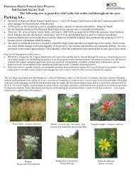
Grass <strong>Swale</strong>. Note stone check dam in front <strong>of</strong> inlet creates<br />
shallow ponding area to encourage infiltration and settling.<br />
Grass <strong>Swale</strong> through residential area. Note flat slope to encourage<br />
infiltration – ponding water gone within hours <strong>of</strong> run<strong>of</strong>f producing<br />
event.<br />
<strong>Grassed</strong> <strong>Swale</strong>
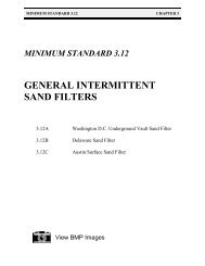
Chapter <strong>3.13</strong><br />
Grass <strong>Swale</strong> with Check Dams. Note significant channel storage<br />
capacity created by check dams. Notched center allows safe<br />
overflow without scour around sides.<br />
<strong>Grassed</strong> <strong>Swale</strong>