PLUMB BOB IN DAMS
PLUMB BOB IN DAMS
PLUMB BOB IN DAMS

You also want an ePaper? Increase the reach of your titles
YUMPU automatically turns print PDFs into web optimized ePapers that Google loves.
WOLF’S <strong>PLUMB</strong> <strong>BOB</strong> NEWS 2010<br />
Issue 11 November 29, 2010<br />
Plumb bobs in <strong>DAMS</strong><br />
Editor: Wolf Ruecker www.plumbbobcollectors.info<br />
<strong>PLUMB</strong> <strong>BOB</strong> <strong>IN</strong> <strong>DAMS</strong><br />
TABLE OF CONTENTS<br />
0. <strong>IN</strong>TRODUCTION ............................................................................................................................. 144<br />
1. WHY A <strong>PLUMB</strong> <strong>BOB</strong> <strong>IN</strong> A DAM? ................................................................................................. 145<br />
2. NORMAL <strong>PLUMB</strong> L<strong>IN</strong>E ................................................................................................................. 146<br />
3. <strong>IN</strong>VERTED or FLOAT<strong>IN</strong>G <strong>PLUMB</strong> L<strong>IN</strong>E ...................................................................................... 148<br />
4. HOOVER or BOLDER DAM ........................................................................................................... 149<br />
5. REMARKS ....................................................................................................................................... 150<br />
0. <strong>IN</strong>TRODUCTION<br />
Dear Fellow Collector,<br />
last year I wrote about the plumb bob used<br />
in the construction of the Washington<br />
Monument.<br />
(See WOLFS<strong>PLUMB</strong><strong>BOB</strong> NEWS 2009-06<br />
Washington Monument Plumb Bob). There the bob<br />
was used to verify the verticality of the<br />
structure.<br />
Since then I have found that plumb bobs<br />
also were used in dams and barrages. During<br />
my research I found that it was really a “life<br />
saver” because it shows very early if<br />
something is wrong with the dam. Those way<br />
precautions could be made in the reinforcement of<br />
the dam to withstand water pressure and to create<br />
an evacuation plan for the cities downstream of<br />
the dam, etc. …<br />
In the construction of dams plumb bobs are<br />
working “quietly” without public notice. For the<br />
collector plumb bobs are perhaps not as interesting<br />
as the more decorative examples that would hang<br />
in our display rooms.<br />
But one aspect is very interesting: In the dams a<br />
certain species of plumb bob may be employed,<br />
“floating” plumb bob, also referred to as an<br />
“inverted” plumb bob. Up to now I thought a<br />
plumb bob must have a weight and be suspended<br />
on a string. We know a lot of inventions, where<br />
other metal (like mercury) was added to make it<br />
heavier. I never heard of a floating plumb bob.<br />
You’ll see the explanation below.<br />
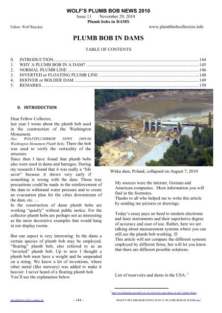
Witka dam, Poland, collapsed on August 7, 2010<br />
My sources were the internet, German and<br />
American companies. More information you will<br />
find in the footnotes.<br />
Thanks to all who helped me to write this article<br />
by sending me pictures or drawings.<br />
Today’s essay pays no heed to modern electronic<br />
and laser instruments and their superlative degree<br />
of accuracy and ease of use. Rather, here we are<br />
talking about measurement systems where you can<br />
still see the plumb bob working. <br />
This article will not compare the different systems<br />
employed by different firms, but will let you know<br />
that there are different possible solutions.<br />
List of reservoirs and dams in the USA: 1<br />
1 http://en.wikipedia.org/wiki/List_of_reservoirs_and_dams_in_the_United_States<br />
plumbbobwolf@t-online.de - 144 - WOLF'S <strong>PLUMB</strong> <strong>BOB</strong> NEWS 2010-11 <strong>PLUMB</strong> <strong>BOB</strong> <strong>IN</strong> <strong>DAMS</strong>.doc
1. WHY A <strong>PLUMB</strong> <strong>BOB</strong> <strong>IN</strong> A DAM?<br />
I found a good definition by Department of<br />
Surveying Engineering University of New<br />
Brunswick Fredericton, N.B., E3B 5A3, Canada<br />
September 1992:<br />
Suspended and inverted plumb lines.<br />
Two kinds of mechanical plumbing are used in<br />
controlling the stability of vertical structures:<br />
(1) suspended plumb lines, and<br />
(2) floating plumb lines also called inverted or<br />
reversed plumb lines.<br />
Inverted plumb lines have an advantage over<br />
suspended plumb lines in the possibility of<br />
monitoring absolute displacements of structures<br />
with respect to deeply anchored points in the<br />
foundation rocks which may be considered as<br />
stable. In the case of power dams, the depth of the<br />
anchors must be 50 m or even more below the<br />
foundation in order to obtain absolute<br />
displacements of the surface points. If invar wire<br />
is used for the inverted plumb line, vertical<br />
movements of the investigated structure with<br />
respect to the bedrock can also be determined<br />
(Boyer and Hamlin, 1985).<br />
Caution must be used in installing plumb lines. If<br />
the plumb line is installed outside the dam, a<br />
vertical pipe of a proper inner diameter should be<br />
used to protect the wire from the wind<br />
(Chrzanowski et al., 1967).<br />
The main concern with floating plumb lines is to<br />
ensure verticality of the boreholes so that the<br />
wire of the plumb line has freedom of motion.<br />
The tank containing the float is generally filled<br />
with water to which some anti-freeze can be added.<br />
The volume of the float should be such as to exert<br />
sufficient tension on the wire. It should also be<br />
noted, however, that in a float tank thermal<br />
convection displacements may easily develop in<br />
consequence of thermal gradients which may<br />
affect measurements to a considerable extent.<br />
Hence in some cases, the whole tank should be<br />
thermally insulated.<br />
Several types of recording devices that measure<br />
displacements of structural points with respect to<br />
the vertical plumb lines are produced by different<br />
companies. The simplest are mechanical or<br />
electromechanical micrometers. With these, the<br />
plumb wire can be positioned with respect to<br />
reference lines of a recording (coordinating)<br />
table to an accuracy of ±0.1 mm or better.<br />
Travelling microscopes may give the same<br />
accuracy.<br />
Automatic sensing and recording is UNB Report<br />
on Deformation Monitoring, 1992 27 possible, for<br />
instance, with a Telecoordinator (Huggenberger.<br />
Switzerland) and with a Telependulum (Telemac,<br />
France). An interesting Automated Vision System<br />
has been developed by Spectron Engineering. The<br />
system uses CCD video cameras to image the<br />
plumb line with a resolution of about 3 g.m over a<br />
range of 75 mm. Several plumb lines at the Glen<br />
Canyon dam and at the Monticello dam in<br />
California have used this system.<br />
Two sources of error which may sometimes be<br />
underestimated by users are: the influence of air<br />
currents, and the spiral shape of wires; see also<br />
Appendix 2. To reduce the influence of the air<br />
pressure, the plumb-line should be protected<br />
within a pipe (e.g., a PVC tube) with openings<br />
only at the reading tables.<br />
The German company GLÖTZL<br />
Baumeßtechnik 2 <strong>PLUMB</strong> WIRE MEASUR.<br />
SYSTEMS has the following definition.<br />
Drawings see below.<br />
Type: GA . . .<br />
Art. No.: 82.01/05<br />
Measuring principle<br />
Pendulum plumb type GAGL<br />
• Fixed point of plumb wire: at the top<br />
• Fixed point of plumb wire: at the bottom<br />
Floating plumb type GARS<br />
• Strain of plumb wire by traction to bottom<br />
• Strain of plumb wire by traction to top<br />
In both cases, the plumb wire is aligning along the<br />
gravity effective at the measuring location, namely<br />
independently from environmental influences<br />
(temperature-, humidity-, barometric pressure<br />
changes a.s.o.).<br />
For barrages, it is generally the objective to unite<br />
the pendulum plumb measurements with the<br />
geodetic measurements. For this purpose, the<br />
horizontal displacement of the wall top is<br />
recorded with a weight plumb, whereby the<br />
elongation of the measuring line is done with a<br />
2 GÖTZL Rheinstetten, Germany www.goetzl.com<br />
plumbbobwolf@t-online.de - 145 - WOLF'S <strong>PLUMB</strong> <strong>BOB</strong> NEWS 2010-11 <strong>PLUMB</strong> <strong>BOB</strong> <strong>IN</strong> <strong>DAMS</strong>.doc
floating plumb for getting an undisplaceable<br />
reference point in the underground.<br />
Floating plumb-plumb wires are anchored in the<br />
stable underground in stainless steel pipings, the<br />
most appropriate exchangeable ones. The spatial<br />
bending line of piping in the underground can be<br />
recorded for an installed plumb wire by means of<br />
a plumb wire deviation probe with the existing<br />
optical or electrical plumb wire measuring<br />
instruments.<br />
Plumb devices are operating with a high accuracy<br />
because its mechanisms are nearly not subject to<br />
friction- and temperature influences. Inclination<br />
movements of a construction can be recorded<br />
without any problems by measurement of the<br />
horizontal displacement of the construction -<br />
relatively to the free hanging plumb wire. A<br />
continuous bending line can be determined if the<br />
relative displacements are measured in several<br />
storeys. Normally, the movements in two<br />
directions (horizontal) are measured at a<br />
measuring station so that a spatial bending line<br />
e.g. in tower constructions can be determined in<br />
case of several measuring points.<br />
In the German language I also found a very detailed<br />
presentation from the Hochschule für Technik,<br />
Wirtschaft und Kultur, Leipzig (FH). Title:<br />
ÜBERWACHUNGSMESSUNGEN AN TALSPERREN. 3<br />
2. NORMAL <strong>PLUMB</strong> L<strong>IN</strong>E<br />
Photos from the German company RICHTER 4<br />
and the Freiberger Präzisionsmechanik FPM 5<br />
showing the installation of a normal plumb line<br />
inside the dam on different levels.<br />
Normal plumb line with measurement<br />
3 FH Leipzig Vortrag:<br />
http://www.cces.de/fileadmin/dl/CCES0304.pdf<br />
4 Richter Deformationsmesstechnik GmbH 09623<br />
Frauenstein www.talsperre.de<br />
5 Freiberger Präzisionsmechanik www.fpm.de<br />
Console Focke<br />
Optical coordimeter<br />
Console for plumb wire measuring system<br />
Overview measuring systems<br />
plumbbobwolf@t-online.de - 146 - WOLF'S <strong>PLUMB</strong> <strong>BOB</strong> NEWS 2010-11 <strong>PLUMB</strong> <strong>BOB</strong> <strong>IN</strong> <strong>DAMS</strong>.doc
Drawings from SME: NORMAL <strong>PLUMB</strong> L<strong>IN</strong>E<br />
Details see footmark 6<br />
NORMAL <strong>PLUMB</strong> L<strong>IN</strong>E<br />
Model SME-2130 is used<br />
to monitor the relative<br />
displacement between<br />
Dam top and Dam base.<br />
System basically<br />
comprises of a plumb<br />
with steel wire hanged<br />
from the top of the dam<br />
for measurement of<br />
relative movement of<br />
plumb in X and Y<br />
direction. The<br />
observation table is<br />
placed at the inspection<br />
gallery. The plumb is a<br />
heavy weight of 10 to 20<br />
kg hanged through a wire<br />
and is submersed in a<br />
thick oil tank under the<br />
frame to dampen the<br />
vibration effect. Two<br />
reference plumbs are<br />
hanged behind plumb<br />
wire in each direction.<br />
Initially the position of<br />
reference plumb and alignment is noted by aligned cross-wire of<br />
microscope. The difference between reference plumb provides<br />
the displacement of dam base from dam top.<br />
SYSTEM by GOETZL 7 (figure right)<br />
Scheme of a weight plumb device<br />
1 Anchoring console<br />
2 Plumb wire clamp<br />
3 Plumb wire<br />
4 Plumb wire meas. device el./opt.<br />
5 Console for pl. wire meas. System<br />
6 Drop screen<br />
7 Weight<br />
8 Dampening fluid<br />
9 Dampening vessel<br />
6 SME SENSORS & MESUREMENTS ENTERPRISES<br />
http://smegeotech.com/final-pdf-2000/sme-2130.pdf<br />
7 GÖTZL Rheinstetten, Germany www.goetzl.com<br />
plumbbobwolf@t-online.de - 147 - WOLF'S <strong>PLUMB</strong> <strong>BOB</strong> NEWS 2010-11 <strong>PLUMB</strong> <strong>BOB</strong> <strong>IN</strong> <strong>DAMS</strong>.doc
3. <strong>IN</strong>VERTED or FLOAT<strong>IN</strong>G <strong>PLUMB</strong><br />
L<strong>IN</strong>E<br />
Drawing by SME:<br />
Details see footmark 8<br />
<strong>IN</strong>VERTED PLUB L<strong>IN</strong>E<br />
Model SME-2140 is used to monitor the<br />
relative displacement between dam base<br />
and the foundation rock. System<br />
basically comprises of a stainless steel<br />
float with a steel water tank and are<br />
placed at the top of the dam or some<br />
time it is kept just above on the<br />
measurement frame. A heavy plumb<br />
with wire is passed through the hole and<br />
grouted at the bottom of the hole with<br />
rock or suitable surface. A support frame<br />
with a top plate having a hole at the<br />
centre mounted with two travailing<br />
microscopes at right angle to each other<br />
for measurement of relative movement<br />
of plumb in X and Y direction are placed<br />
at the inspection gallery. The other end<br />
of the wire is fixed with float submersed<br />
in a water tank placed at the top of the<br />
structure. For measurement the<br />
difference between reference plumb<br />
provides the displacement position of<br />
dam base from the foundation.<br />
GÖTZL 9<br />
Scheme of a floating plumb device<br />
1 Float vessel<br />
2 Float<br />
3 Console for float vessel<br />
4 Tension lock with hook and eye<br />
5 Plumb wire clamp/ screw-type sleeve<br />
6 Plumb wire meas. device el./opt.<br />
7 Console for pl. wire meas. System<br />
8 Plumb wire<br />
9 Drop screen<br />
10 Plumb wire anchor<br />
11 Tight closure of piping<br />
12 Plumb wire deviation probe<br />
13 Reel for tape measure<br />
8 SME SENSORS & MESUREMENTS ENTERPRISES<br />
http://smegeotech.com/final-pdf-2000/sme-2140.pdf<br />
9 GLÖTZL Gesellschaft für Baumesstechnik mbH 76287<br />
Rheinstetten www.gloetzl.com<br />
plumbbobwolf@t-online.de - 148 - WOLF'S <strong>PLUMB</strong> <strong>BOB</strong> NEWS 2010-11 <strong>PLUMB</strong> <strong>BOB</strong> <strong>IN</strong> <strong>DAMS</strong>.doc
4. HOOVER or BOLDER DAM<br />
http://www.usbr.gov/<br />
Bureau of Reclamation: Lower Colorado Region -<br />
Hoover Dam Historical Collection<br />
More information on<br />
http://www.usbr.gov/lc/hooverdam/collection.html<br />
From Wikipedia 10 : Hoover Dam, once known as<br />
Boulder Dam, is a concrete arch-gravity<br />
dam in the Black Canyon of the Colorado<br />
River, on the border between the US states<br />
of Arizona and Nevada. It was constructed<br />
between 1931 and 1936 during the Great<br />
Depression, and was dedicated on<br />
September 30, 1935, by President Franklin<br />
Roosevelt. Its construction was the result<br />
of a massive effort involving thousands of<br />
workers, and cost over one hundred lives.<br />
Since about 1900, the Black Canyon and<br />
nearby Boulder Canyon had been<br />
investigated for their potential to support a<br />
dam that would control floods, provide<br />
irrigation water and produce hydroelectric<br />
power. In 1928, Congress authorized the<br />
project. The winning bid to build the dam<br />
was submitted by a consortium called Six<br />
Companies, Inc., which began construction<br />
on the dam in early 1931. Such a large<br />
concrete structure had never been built<br />
before, and some of the techniques were<br />
unproven. The torrid summer weather and the lack<br />
of facilities near the site also presented<br />
difficulties. Nevertheless, Six Companies turned<br />
over the dam to the federal government on March<br />
1, 1936, more than two years ahead of schedule.<br />
10 http://en.wikipedia.org/wiki/Hoover_Dam<br />
worker using a pb to plumb the slide gate<br />
guides<br />
Figures right: plumb bobs<br />
used during construction.<br />
plumbbobwolf@t-online.de - 149 - WOLF'S <strong>PLUMB</strong> <strong>BOB</strong> NEWS 2010-11 <strong>PLUMB</strong> <strong>BOB</strong> <strong>IN</strong> <strong>DAMS</strong>.doc
5. REMARKS<br />
Did YOU already see a dam or barrage <strong>IN</strong>SIDE? I would be glad to get photos from this visit. Thank you.<br />
This is an article of the monthly published WOLF’S <strong>PLUMB</strong> <strong>BOB</strong> NEWS that is sent on demand as PDF-file<br />
attachment by email. FREE.<br />
You can see all former and future publications on my website www.plumbbobcollectors.info<br />
Remarks and contact by email:<br />
plumbbobwolf@t-online.de<br />
Thank you for your interest!<br />
Wolf Ruecker<br />
plumbbobwolf@t-online.de - 150 - WOLF'S <strong>PLUMB</strong> <strong>BOB</strong> NEWS 2010-11 <strong>PLUMB</strong> <strong>BOB</strong> <strong>IN</strong> <strong>DAMS</strong>.doc