Switchgear selection and application guide Types ... - Siemens Energy
Switchgear selection and application guide Types ... - Siemens Energy
Switchgear selection and application guide Types ... - Siemens Energy

You also want an ePaper? Increase the reach of your titles
YUMPU automatically turns print PDFs into web optimized ePapers that Google loves.
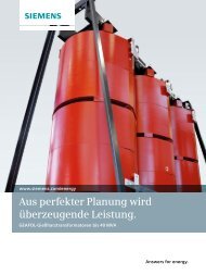
www.usa.siemens.com/mvswitchgear<br />
<strong>Switchgear</strong> <strong>selection</strong><br />
<strong>and</strong> <strong>application</strong> <strong>guide</strong><br />
<strong>Types</strong> GM-SG <strong>and</strong> GM-SG-AR 5 kV to 15 kV metal-clad<br />
Answers for infrastructure.
Selection <strong>and</strong><br />
<strong>application</strong> <strong>guide</strong><br />
This <strong>selection</strong> <strong>and</strong> <strong>application</strong> <strong>guide</strong> for the<br />
types GM-SG <strong>and</strong> GM-SG-AR 5 kV-15 kV metalclad<br />
switchgear presents you the features,<br />
benefits, ratings <strong>and</strong> dimensions of the<br />
equipment.<br />
<strong>Siemens</strong>‘ experience gained in over 80<br />
years of supplying metal-clad switchgear in<br />
the U.S. has been captured in the type<br />
GM-SG-AR design. The objective has been to<br />
incorporate features designed to provide<br />
safety, while simplifying operation,<br />
maintenance <strong>and</strong> minimizing installation<br />
cost.<br />
Table of contents<br />
Overview 04 – 08<br />
Construction 09 – 18<br />
Accessories 19 – 20<br />
Protective relays 21<br />
Vacuum circuit breakers 22 – 29<br />
Generator vacuum circuit breakers 30 – 34<br />
Technical data 35 – 43<br />
Stacking versatility 44<br />
Side views 45 – 46<br />
Anchoring <strong>and</strong> section arrangements 47 – 51
4<br />
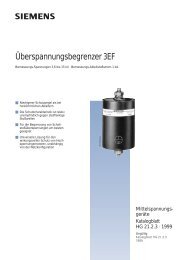
Figure 1: <strong>Types</strong> GM-SG <strong>and</strong> GM-SG-<br />
AR medium-voltage switchgear<br />
lineups<br />
Overview<br />
Introduction<br />
Type GM-SG non-arc-resistant<br />
<strong>Siemens</strong>‘ experience gained in over 80 years<br />
of supplying metal-clad switchgear in the<br />
U.S. has been captured in the type GM-SG<br />
family of switchgear. The objective has been<br />
to incorporate features designed to provide<br />
safety, while simplifying operation,<br />
maintenance <strong>and</strong> minimizing installation<br />
cost.<br />
The <strong>Siemens</strong> type GM-SG family of metalclad<br />
switchgear assemblies, with horizontal<br />
drawout type GMSG vacuum circuit<br />
breakers, takes advantage of the latest<br />
developments in vacuum interrupter<br />
technology. Up to two circuit breakers can<br />
be stacked in a single vertical section,<br />
allowing significant space savings.<br />
The equipment meets or exceeds the latest<br />
st<strong>and</strong>ards of ANSI, IEEE <strong>and</strong> NEMA.<br />
Type GM-SG switchgear is designed for use<br />
in industrial plants, commercial buildings,<br />
electric utility systems, cogeneration<br />
installations <strong>and</strong> other electrical systems.<br />
Type GM-SG-AR arc-resistant<br />
It is commonly used for protection <strong>and</strong><br />
switching of transformers, motors,<br />
generators, capacitors, buses, distribution<br />
feeder lines <strong>and</strong>, in general, for protection<br />
of any medium-voltage power circuit.<br />
The type GM-SG family includes both<br />
conventional type GM-SG non-arc-resistant<br />
switchgear, <strong>and</strong> type GM-SG-AR arc-resistant<br />
switchgear, both presented in Figure 1:<br />
<strong>Types</strong> GM-SG <strong>and</strong> GM-SG-AR mediumvoltage<br />
switchgear lineups.<br />
The type GM-SG-AR arc-resistant switchgear<br />
has been tested to ANSI/IEEE C37.20.7<br />
requirements for accessibility type 2B. This<br />
construction is intended to provide an<br />
additional degree of protection to personnel<br />
in close proximity to the equipment in the<br />
event of an internal arcing fault.<br />
The switchgear structure <strong>and</strong> the drawout<br />
vacuum circuit breaker are an integrated<br />
design, with dielectric, thermal <strong>and</strong><br />
interruption integrity built directly into the<br />
basic design, not as an afterthought.
13<br />
14<br />
13<br />
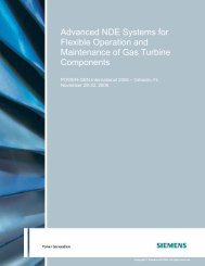
Designation Enclosure type<br />
1. Type GMSG vacuum circuit breaker<br />
GM-SG Non-arc-resistant, indoor<br />
OGM-SG Non-arc-resistant, non-walk-in outdoor<br />
SGM-SG Non-arc-resistant, single-aisle outdoor, Shelter-Clad<br />
GM-SG-AR Arc-resistant indoor<br />
SGM-SG-AR Arc-resistant, single-aisle outdoor, Shelter-Clad<br />
2. St<strong>and</strong>ard accuracy current transformers (CTs) -<br />
up to two per bushing<br />
3. Isolated protective relay <strong>and</strong> instrument<br />
compartment<br />
4. Inter-unit wiring area<br />
5. Pressure relief channel (PRC) (for arc-resistant<br />
version only)<br />
6. Ground bar<br />
7. Ground sensor CT<br />
8. Main bus bars<br />
3<br />
4<br />
1<br />
1<br />
2<br />
2<br />
2<br />
2<br />
5<br />
8<br />
8<br />
8<br />
10<br />
11<br />
11<br />
6 7<br />
9. Power cable trough<br />
7<br />
12<br />
10. Removable bus compartment barrier<br />
11. Surge arresters<br />
12. Outgoing cable lugs (downfeed shown)<br />
13. Circuit breaker compartment door:<br />
Non-arc-resistant - suitable for relays <strong>and</strong><br />
control devices<br />
Arc-resistant - normally not suitable for relays<br />
<strong>and</strong> control devices. Options available. Consult<br />
factory.<br />
14. Low-voltage compartment door suitable for<br />
relays <strong>and</strong> control devices<br />
9<br />
Table 1: Type GM-SG family<br />
designation<br />
Figure 2: <strong>Types</strong> GM-SG or GM-SG-AR<br />
medium-voltage switchgear 1,200 A<br />
or 2,000 A circuit breaker section<br />
5
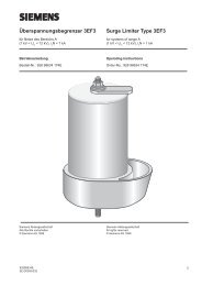
6<br />
Figure 3: Floor rollout/roll-in<br />
<strong>Siemens</strong> type 3AH3 operating mechanism<br />
The type GMSG circuit breaker uses the<br />
proven <strong>Siemens</strong> type 3AH3 stored-energy<br />
operating mechanism. This operator is an<br />
evolution of the type 3A family of operators<br />
first introduced in 1976. Over 60,000 type<br />
3AH3 operating mechanisms have been<br />
produced since 1998.<br />
Faster interruption<br />
St<strong>and</strong>ard interrupting time is five-cycles<br />
with an option available for three-cycle<br />
interrupting time.<br />
<strong>Siemens</strong> vacuum interrupters<br />
The vacuum interrupters used in the type<br />
GMSG circuit breaker are manufactured by<br />
<strong>Siemens</strong> <strong>and</strong> have been proven in thous<strong>and</strong>s<br />
of installations since 1976. The chromecopper<br />
contacts used in these vacuum<br />
interrupters are designed to assure low<br />
chopping levels <strong>and</strong> eliminate the need for<br />
surge protection on most circuits.<br />
Front-mounted operating mechanism<br />
The simple type GMSG operating<br />
mechanism makes maintenance <strong>and</strong><br />
inspection easy. The mechanism is located<br />
on the front of the circuit breaker rather<br />
than underneath.<br />
Maintenance intervals<br />
If applied under ANSl “usual service”<br />
conditions, maintenance of the circuit<br />
breaker mechanism is designed to be<br />
needed at 10-year intervals.<br />
Maintenance of the switchgear cubicle is<br />
recommended at five-year intervals <strong>and</strong><br />
primarily consists of cleaning insulation.<br />
Generator vacuum circuit breakers<br />
Type GMSG-GCB generator vacuum circuit<br />
breakers can also be installed in types<br />
GM-SG <strong>and</strong> GM-SG-AR structures. These<br />
circuit breakers are derived from the basic<br />
type GMSG vacuum circuit breaker, but are<br />
specifically designed <strong>and</strong> tested to meet the<br />
requirements of IEEE Std C37.013 for<br />
generator circuit breakers.<br />
Generator circuit breakers are not<br />
interchangeable with st<strong>and</strong>ard (nongenerator)<br />
circuit breakers.<br />
Floor rollout<br />
No lift truck or dolly is needed to insert or<br />
remove circuit breakers in the lower cell of<br />
switchgear located at floor level. For indoor<br />
switchgear located on a raised<br />
“housekeeping” pad or for outdoor nonwalk-in<br />
switchgear, a lift truck is required to<br />
h<strong>and</strong>le circuit breakers.<br />
“Universal” spare circuit breaker<br />
(up to 50 kA)<br />
The physical configuration <strong>and</strong> interlock<br />
logic allow the use of a single circuit breaker<br />
to serve as a “universal” spare breaker at an<br />
installation site for up to 50 kA. The<br />
interlock logic checks the principal rating<br />
characteristics (continuous current,<br />
maximum voltage <strong>and</strong> interrupting current)<br />
<strong>and</strong> allows a circuit breaker to be inserted in<br />
any circuit breaker cell provided that the<br />
circuit breaker equals or exceeds the ratings<br />
required by the cell.<br />
Generator circuit breakers are not<br />
interchangeable with st<strong>and</strong>ard (nongenerator)<br />
circuit breakers.<br />
“Universal” spare circuit breaker (63 kA)<br />
The concept described above (for up to<br />
50 kA) also applies for equipment rated<br />
63 kA, within the 63 kA rating. Circuit<br />
breakers rated 63 kA cannot be used in<br />
equipment rated 50 kA or lower.<br />
Generator circuit breakers are not<br />
interchangeable with st<strong>and</strong>ard (nongenerator)<br />
circuit breakers.
Single source responsibility<br />
Single source responsibility is assured since<br />
the complete equipment is designed by<br />
<strong>Siemens</strong> <strong>and</strong> is manufactured <strong>and</strong> tested in<br />
a single <strong>Siemens</strong> facility. The vacuum circuit<br />
breakers are checked in the switchgear cells<br />
as part of production testing. The vacuum<br />
circuit breakers are shipped in the<br />
switchgear to assure interchangeability <strong>and</strong><br />
to reduce the possibility of damage to the<br />
circuit breakers during shipment.<br />
Full ANSI design background<br />
Full design integrity is managed <strong>and</strong><br />
controlled by <strong>Siemens</strong>. ANSl/IEEE C37.09<br />
<strong>and</strong> C37.20.2 require design tests on circuit<br />
breakers <strong>and</strong> structures together. The type<br />
3AH3 operator design originates in <strong>Siemens</strong>‘<br />
global center of competence for circuit<br />
breakers in Berlin, <strong>and</strong> final assembly of<br />
both the drawout type GMSG circuit breaker<br />
<strong>and</strong> the GM-SG family of switchgear occurs<br />
in a single facility. <strong>Siemens</strong> controls the<br />
entire process from design concept to<br />
production. Records are maintained to<br />
document compliance with ANSl/IEEE<br />
st<strong>and</strong>ards.<br />
UL or C-UL Listing available<br />
Where the arrangement of components<br />
allows, UL or C-UL Listing (for use in<br />
Canada) is available across the full range of<br />
the GM-SG family of switchgear.<br />
Quality systems<br />
Facilities involved with <strong>application</strong>,<br />
engineering, design <strong>and</strong> production are<br />
certified to ISO 9001 requirements.<br />
Structural flexibility<br />
<strong>Siemens</strong> GM-SG family of metal-clad<br />
switchgear provides enhanced flexibility in<br />
locating circuit breaker, auxiliary <strong>and</strong><br />
metering cells within the structure layout.<br />
Circuit breakers rated 1,200 A, 2,000 A <strong>and</strong><br />
3,000 A may be located in upper or lower<br />
cell positions.<br />
Bus sectionalizing (tie) circuit breaker cells<br />
may be located on the upper or lower levels<br />
<strong>and</strong> are ordinarily located next to an<br />
auxiliary cell on the same level to<br />
accommodate transition bus work.<br />
3,000 A circuit breakers can be located<br />
either in the bottom cell or the top cell of a<br />
vertical section.<br />
If a 3,000 A circuit breaker is located in the<br />
lower cell, the upper cell may be used for<br />
metering devices only.<br />
If a 3,000 A circuit breaker is in the upper<br />
cell, the lower cell may be used to house a<br />
set of drawout voltage transformers, a<br />
drawout control power transformer or<br />
rollout fuses for a remote control power<br />
transformer.<br />
The 3,000 A circuit breaker may be used for<br />
4,000 A continuous current <strong>application</strong>s,<br />
with the addition of fan cooling equipment<br />
in the auxiliary cell above the circuit<br />
breaker. This <strong>application</strong> of fan cooling is<br />
appropriate if loads above 3,000 A are<br />
infrequent as, for example, in the case of a<br />
fan-cooled rating on a power transformer.<br />
Each vertical section contains the main bus<br />
bar compartment plus a rear compartment<br />
for incoming <strong>and</strong> outgoing connections. The<br />
front portion of the vertical section contains<br />
a central protective relay <strong>and</strong> instrument<br />
compartment as shown in Figure 2: <strong>Types</strong><br />
GM-SG or GM-SG-AR medium-voltage<br />
switchgear 1,200 A or 2,000 A circuit<br />
breaker section on page 5. The switchgear is<br />
normally designed so that additional vertical<br />
sections may be added in the future.<br />
Enclosure design<br />
The type GM-SG family design includes full<br />
ANSI/IEEE C37.20.2 metal-clad construction.<br />
This means complete enclosure of all live<br />
parts <strong>and</strong> separation of major elements of<br />
the circuit to retard the spread of faults to<br />
other compartments.<br />
Removable plates permit access to all<br />
compartments. On non-arc-resistant<br />
versions, rear panels are individually<br />
removable to allow separate access either to<br />
downfeed or upfeed cable connections. On<br />
arc-resistant versions, rear panels are<br />
hinged <strong>and</strong> bolted.<br />
The structure is constructed of bolted steel<br />
for better dimensional control than with<br />
welded designs. Sheet steel inter-unit<br />
barriers extend the full height <strong>and</strong> depth of<br />
each vertical section for isolating adjacent<br />
sections. The ground bus extends the entire<br />
length of the complete switchgear lineup<br />
<strong>and</strong> to all circuit breaker cells.<br />
Figure 4: Stacking flexibility<br />
7
8<br />
Figure 5: Type GMSG 63 kA circuit<br />
breaker<br />
Circuit breaker interchangeability<br />
The type GM-SG family structures <strong>and</strong> the<br />
removable type GMSG circuit breaker<br />
element are both built to master fixtures so<br />
circuit breakers of the same ratings are<br />
interchangeable with each other even if the<br />
circuit breaker is required for use with a cell<br />
with “provisions only” supplied years earlier.<br />
The type GMSG circuit breaker is not<br />
interchangeable with the older designs.<br />
A circuit breaker of higher rating (up to<br />
50 kA) can be used in a cell of equal or<br />
lower rating. For example, a 3,000 A 50 kA<br />
15 kV circuit breaker can be used in a<br />
1,200 A 25 kA 15 kV circuit breaker cell.<br />
Additionally, circuit breakers are<br />
interchangeable between arc-resistant <strong>and</strong><br />
non-arc-resistant cells.<br />
The same is true for 63 kA rated circuit<br />
breakers. The 63 kA rated circuit breakers,<br />
however, can only be used in 63 kA rated<br />
cells, <strong>and</strong> lower rated circuit breakers cannot<br />
be used in 63 kA rated cells.<br />
Generator circuit breakers are not<br />
interchangeable with st<strong>and</strong>ard (nongenerator)<br />
circuit breakers.<br />
Tested to ANSl/IEEE st<strong>and</strong>ards<br />
<strong>Siemens</strong> type GM-SG switchgear is tested to<br />
meet the requirements of ANSl/IEEE<br />
st<strong>and</strong>ards. A complete design test program,<br />
including short-circuit interruption, loadcurrent<br />
switching, continuous current,<br />
mechanical endurance, close <strong>and</strong> latch<br />
current, short time <strong>and</strong> momentary<br />
withst<strong>and</strong>, impulse withst<strong>and</strong> <strong>and</strong> the other<br />
tests required by the st<strong>and</strong>ards, has been<br />
successfully completed. These tests<br />
encompass the complete equipment design,<br />
including both the switchgear structure <strong>and</strong><br />
the circuit breaker removable element.<br />
Production tests in accordance with<br />
ANSl/IEEE st<strong>and</strong>ards are performed on every<br />
group of switchgear <strong>and</strong> on each circuit<br />
breaker. Certified copies of all test data can<br />
be furnished to customers upon request.<br />
Type GM-SG non-arc-resistant switchgear is<br />
not classified as arc-resistant switchgear <strong>and</strong><br />
has not been tested for resistance to<br />
internal arcing per IEEE C37.20.7.<br />
Type GM-SG-AR arc-resistant switchgear is<br />
classified as arc-resistant switchgear <strong>and</strong> has<br />
been tested for resistance to internal arcing<br />
per IEEE C37.20.7 <strong>and</strong> has been qualified to<br />
carry a type 2B accessibility rating. The arcresistant<br />
features are intended to provide an<br />
additional degree of protection to personnel<br />
in close proximity to the equipment in event<br />
of an internal arcing fault while the<br />
equipment is operating under normal<br />
conditions.<br />
Qualification to seismic <strong>and</strong> wind loading<br />
requirements of various codes (for example,<br />
IBC, UBC <strong>and</strong> IEEE 693) is available. Consult<br />
<strong>Siemens</strong> with detailed requirements.<br />
UL or C-UL Listing available<br />
When specified, if the component<br />
configuration allows, the switchgear can be<br />
provided with a UL or C-UL (for use in<br />
Canada) label, indicating conformance to<br />
the requirements of ANSl C37.54 <strong>and</strong> ANSI<br />
C37.55.
Enclosures<br />
The GM-SG family structures are constructed<br />
of bolted 11-gauge steel <strong>and</strong> features slots<br />
<strong>and</strong> tabs to capitalize on CNC machinery for<br />
better dimensional control than welded<br />
designs have.<br />
The structures are finished using a<br />
thermosetting polyester-powder coating<br />
with a textured appearance that is applied<br />
with electrostatic equipment. This method<br />
provides a durable finish that is highly<br />
resistant to marring <strong>and</strong> scratches. The<br />
st<strong>and</strong>ard finish is ANSI light gray. For<br />
surfaces exposed to weather, an additive is<br />
used to increase resistance to fading <strong>and</strong><br />
improve salt-spray performance.<br />
Interior plates for mounting control devices<br />
<strong>and</strong> wiring are finished bright white without<br />
texturing to allow for easy viewing of<br />
wiring.<br />
To accomodate large quantities of incoming/<br />
outgoing cables, bolt-on rear extensions are<br />
available in 15” (381 mm) <strong>and</strong> 30”<br />
(762 mm) depths.<br />
Pressure relief channel<br />
The arc-resistant structures also feature<br />
exhaust channels between vertical sections<br />
that direct the hot gases overpressure <strong>and</strong><br />
other arc by-products upward <strong>and</strong> into a topmounted<br />
pressure relief channel (PRC), <strong>and</strong><br />
away from personnel in close proximity to the<br />
equipment.<br />
Once inside the PRC, the hot gases <strong>and</strong> arc<br />
by-products exp<strong>and</strong> to reduce the<br />
overpressure. The PRC runs the entire length<br />
of a lineup of equipment <strong>and</strong> can be<br />
segregated internally to isolate groups of<br />
vertical sections of the lineup (for example, a<br />
tie-breaker section.)<br />
The PRC is factory installed to reduce<br />
installation time <strong>and</strong> is compact to permit<br />
over-the-road transportation without the<br />
need for special permits or equipment.<br />
Construction<br />
Figure 6: Type GM-SG-AR switchgear<br />
Exhaust plenum<br />
An exhaust plenum system attaches to the<br />
rear, front <strong>and</strong> sides or on top of the PRC<br />
(front connection must be coordinated with<br />
the circuit breaker lift truck) <strong>and</strong> carries the<br />
hot gases <strong>and</strong> arc by-products to the outside<br />
environment. One plenum run is required for<br />
every 14 vertical sections (for example, a<br />
lineup of 16 vertical sections would have the<br />
PRC segregated into two groups with a<br />
maximum of 14 <strong>and</strong> minimum of two vertical<br />
sections with one plenum for each group.)<br />
The plenum system is comprised of st<strong>and</strong>ard<br />
modular sections supplied assembled that are<br />
bolted together in the field to form a plenum<br />
run. The plenum run is designed to be<br />
suspended from the ceiling or supported from<br />
below similar to metal-enclosed bus duct.<br />
Many configurations are possible for the<br />
plenum system (for example, elbows <strong>and</strong><br />
inclines); however, the plenum system must<br />
pass through an exterior wall horizontally to<br />
the outside environment (consult <strong>Siemens</strong> for<br />
a particular <strong>application</strong>). <strong>Siemens</strong> must<br />
provide the plenum system, however,does<br />
not supply the suspension/mounting<br />
components for the plenum system.<br />
9
10<br />
Figure 7: Type GM-SG-AR switchgear<br />
An exit section at the end of the plenum run<br />
is used to penetrate the exterior (noncombustible)<br />
wall of the building. It is<br />
designed to accommodate a wall thickness<br />
from 2” (51 mm) to 18” (457 mm) as<br />
st<strong>and</strong>ard, <strong>and</strong> is weather tight. On the exit<br />
section, an exhaust flap opens (in the event<br />
of an arcing fault due to the overpressure in<br />
the plenum) to allow gases <strong>and</strong> arc<br />
by-products to escape to the outside<br />
environment into a restricted access area with<br />
the minimum dimensions as presented in<br />
Figure 8: Installation of exhaust plenum exit<br />
on page 11.<br />
Ventilation<br />
Ventilation openings are provided on all<br />
GM-SG family structures <strong>and</strong> can be screened<br />
or filtered as an option. A minimum clearance<br />
of 10” (254 mm) above <strong>and</strong> 2” (51 mm)<br />
behind the equipment must be maintained to<br />
the nearest wall, equipment or other<br />
obstruction to allow for proper cooling of the<br />
equipment.<br />
For the arc-resistant structures, these<br />
ventilation openings feature internal flaps<br />
that close in the event of internal arcing to<br />
minimize the escape of hot gases through<br />
these openings. In addition to clearances<br />
required for ventilation, arc-resistant<br />
structures require clearances around the<br />
equipment for personnel safety as follows:<br />
If the switchgear is installed with working<br />
space to the rear of the equipment that<br />
could be occupied by maintenance,<br />
operating or other personnel, a minimum<br />
of 37” (940 mm) of clearance must be<br />
provided from the switchgear to the<br />
nearest wall, equipment or other<br />
obstruction.<br />
If the switchgear is installed with working<br />
space beside the equipment that could be<br />
occupied by maintenance, operating or<br />
other personnel, a minimum of 24”<br />
(610 mm) of clearance must be provided<br />
from the switchgear to the nearest wall,<br />
equipment or other obstruction.<br />
If the switchgear is installed with space<br />
beside the equipment <strong>and</strong> this space is<br />
designated <strong>and</strong> blocked so that<br />
maintenance, operating or other personnel<br />
are excluded from the space, a minimum of<br />
6” (152 mm) of clearance must be provided<br />
from the switchgear to the nearest wall,<br />
equipment or other obstruction.<br />
If the switchgear is installed inside a pwoer<br />
equipment center (or powerhouse) or<br />
similar outer enclosure, where access to<br />
the rear of the equipment is provided by<br />
means of doors or removable panels on the<br />
outer enclosure, a minimum of 6”<br />
(152 mm) of clearance must be provided<br />
between the rearmost extension of the<br />
ventilation openings on the switchgear <strong>and</strong><br />
the enclosure.
Identification Description<br />
A Exhaust plenum section<br />
B 3/8-16 hardware<br />
C Exhaust exit section<br />
D Exhaust flap closed<br />
E Screw may be removed if inside a wall<br />
F Exhaust flap open<br />
G Wall (non-combustible)<br />
H Field caulk all around<br />
I Fenced (or otherwise protected) area with restricted access<br />
J Exterior (building)<br />
K Exhaust plenum exit<br />
A<br />
Indoor<br />
0.38 (10)<br />
(minimum clearance)<br />
E<br />
G<br />
H<br />
B<br />
Outdoor<br />
18.0 (457) (maximum wall thickness)<br />
2.0 (51) (minimum wall thickness)<br />
F<br />
C<br />
D<br />
Dimensions in inches (mm)<br />
.45 (11)<br />
(Hardware<br />
protrusion)<br />
Figure 8: Installation of exhaust plenum exit<br />
The detail below shows the minimum<br />
recommended clearance from the exhaust plenum<br />
exit. When the equipment is operating, this area<br />
should be kept clear of personnel <strong>and</strong>/or<br />
combustible or flammable materials.<br />
H<br />
14.62 (371)<br />
(Exhaust exit section<br />
outside height)<br />
24.12 (613) (Exhaust exit<br />
section outside width)<br />
Wall cutout<br />
26.62 (676)<br />
K<br />
J<br />
10' (3 m)<br />
5' (1.5 m)<br />
I<br />
Clearance required<br />
around exhaust<br />
plenum exit.<br />
Wall cutout<br />
15.14 (385)<br />
11
Figure 9: Cable trough in lower<br />
cable compartment to isolate cables<br />
from circuit breaker in upper<br />
compartment<br />
Figure 10: Central compartment for<br />
panel devices<br />
Figure 11: Electric racking accessory<br />
12<br />
<strong>Switchgear</strong> compartments<br />
Vacuum circuit breaker cell<br />
The circuit breaker cell is a bolted, reinforced,<br />
sheet steel enclosure with provisions for a<br />
type GMSG vacuum circuit breaker. It includes<br />
a hinged front door, inter-compartment <strong>and</strong><br />
inter-unit barriers, primary <strong>and</strong> secondary<br />
disconnects, racking mechanism, interlocks,<br />
instruments <strong>and</strong> relays, control wiring <strong>and</strong><br />
devices <strong>and</strong> current transformers, as required<br />
by the <strong>application</strong>.<br />
Vacuum circuit breaker element<br />
The type GMSG vacuum circuit breaker<br />
includes a stored-energy operating<br />
mechanism, primary <strong>and</strong> secondary<br />
disconnects, auxiliary switch, ground contact,<br />
control wiring <strong>and</strong> interlocks.<br />
Auxiliary cell<br />
An auxiliary cell is similar to a circuit breaker<br />
cell, except without provisions for a circuit<br />
breaker. Space may be used for voltage<br />
transformers (VTs), control power<br />
transformers (CPTs) or rollout fuse trays, or<br />
other auxiliary devices.<br />
For type GM-SG non-arc-resistant switchgear,<br />
the front panel is hinged.<br />
For type GM-SG-AR arc-resistant switchgear,<br />
the front panel is hinged <strong>and</strong> also interlocked<br />
with the VT, CPT or rollout fuse tray, so that<br />
the rollout tray must be withdrawn<br />
(disconnected) before the compartment door<br />
can be opened.<br />
Bus compartment<br />
The bus compartment is a separately<br />
enclosed space for three-phase insulated<br />
main power bus bars, supports <strong>and</strong><br />
connections to circuit breaker <strong>and</strong> auxiliary<br />
cells.<br />
Primary termination compartment<br />
The rear area of the unit includes space for<br />
connecting incoming or outgoing power<br />
cables, bus duct connections, transformer<br />
connections or surge protection devices. In<br />
stacked configurations, outgoing power<br />
connections for the upper cell are isolated<br />
from those for the lower cell.<br />
Circuit breaker cell features<br />
Relay <strong>and</strong> instrument space<br />
For non-arc-resistant equipment, the circuit<br />
breaker cell front door is suitable for<br />
mounting the most common relays, meters,<br />
test switches, control switches <strong>and</strong> similar<br />
devices typically used on metal-clad<br />
switchgear.<br />
For arc-resistant equipment, the circuit<br />
breaker cell front door space is not normally<br />
suitable for protective relays <strong>and</strong> control<br />
devices. Consult factory for available options.<br />
Closed door racking<br />
The circuit breaker can be racked in or racked<br />
out with the cell door open or closed.<br />
For non-arc-resistant equipment <strong>and</strong> for arcresistant<br />
equipment, the mechanism includes<br />
an indicator to show the racking mechanism<br />
position with the door closed.<br />
For arc-resistant equipment, the circuit<br />
breaker is interlocked so that it can be racked<br />
only with the compartment door closed <strong>and</strong><br />
latched.<br />
For racking, a manual drive crank or an<br />
optional electric motor drive may be used for<br />
either type of equipment,<br />
Electrical racking accessory (optional)<br />
An electrical racking motor accessory is<br />
available. This consists of a motor drive<br />
assembly which installs (without tools) on<br />
mounting brackets on the switchgear front<br />
panel of a circuit breaker compartment. The<br />
unit includes a power cord, which can be<br />
plugged into a duplex receptacle in the<br />
vicinity of the switchgear, plus a control<br />
cable, which allows the operator to control<br />
the racking operation from a distance. An<br />
alternative arrangement is available, which<br />
includes a control box that can be mounted at<br />
a distance from the switchgear <strong>and</strong><br />
permanently connected to control power. In<br />
turn, the racking motor can be connected to<br />
the control box with a long cord.<br />
Floor rollout<br />
Circuit breakers in the lower cell can be rolled<br />
out directly on the floor in front of the unit<br />
without a h<strong>and</strong>ling device, lift truck, or hoist<br />
for indoor (if not on raised “housekeeping”<br />
pad) <strong>and</strong> Shelter-Clad installations. A lift truck<br />
accessory is optionally available for h<strong>and</strong>ling<br />
circuit breakers in upper cells or in non-walkin<br />
outdoor enclosures.
Current transformers<br />
Front-access current transformers may be<br />
mounted around both the upper <strong>and</strong> lower<br />
stationary primary disconnect bushings. Up<br />
to four st<strong>and</strong>ard accuracy current<br />
transformers per phase may be located in<br />
each circuit breaker cell.<br />
Interlocks<br />
Interlocks prevent moving a closed circuit<br />
breaker in the cell by preventing engagement<br />
of the racking crank (or electric racking<br />
accessory) if the circuit breaker is closed.<br />
A second interlock lever holds the circuit<br />
breaker mechanically <strong>and</strong> electrically trip free<br />
between positions. The racking mechanism<br />
can be padlocked to restrict unauthorized<br />
racking of the circuit breaker.<br />
Additional interlocks for arc-resistant<br />
equipment prevent racking of a circuit<br />
breaker in the cell unless the cell door is<br />
closed <strong>and</strong> latched.<br />
Separate padlock provisions may be used to<br />
hold the circuit breaker in the trip-free<br />
condition.<br />
Automatic shutters<br />
Automatically operated grounded steel<br />
shutters allow or block access to the<br />
stationary primary disconnects. The shutters<br />
are opened by the circuit breaker as it moves<br />
toward the connected position. The shutters<br />
close as the circuit breaker is racked away<br />
from the connected position to the test<br />
position. The shutters remain closed until<br />
they are forced open by insertion of the<br />
circuit breaker. This design enhances<br />
protection for personnel compared to shutters<br />
that are only linked to the racking mechanism<br />
only.<br />
Primary disconnects<br />
The cubicle stationary primary disconnect<br />
contacts are recessed inside insulated<br />
assemblies <strong>and</strong> are located behind grounded<br />
steel shutters to prevent accidental contact<br />
when the circuit breaker is withdrawn. The<br />
primary disconnect finger clusters are<br />
mounted on the circuit breaker.<br />
Secondary disconnects<br />
The cubicle-mounted stationary disconnect<br />
contacts mate with spring-loaded secondary<br />
contacts on the side of the circuit breaker.<br />
The secondary disconnects automatically<br />
engage in both the test <strong>and</strong> connected<br />
positions <strong>and</strong> they remain engaged between<br />
these positions.<br />
Mechanism-operated cell (MOC) switch<br />
When required, up to 24 stages of the MOC<br />
auxiliary switch can be mounted in the circuit<br />
breaker cell. All spare MOC contacts are wired<br />
to accessible terminal blocks for user<br />
connections. These MOC switches are<br />
operated only when the circuit breaker is in<br />
the connected position. Optionally, they may<br />
be arranged to operate in both the connected<br />
<strong>and</strong> test positions.<br />
Truck-operated cell (TOC) switch<br />
When required, up to 12 stages of TOC switch<br />
can be mounted in the circuit breaker cell. All<br />
spare TOC contacts are wired to accessible<br />
terminal blocks for user connections.<br />
Unobstructed terminal block space<br />
Terminal block areas are located on each side<br />
of circuit breaker or auxiliary cells. Since the<br />
racking system components are not mounted<br />
on the cubicle sides, the side-mounted<br />
terminal blocks are not obstructed as in other<br />
designs. Installation of field wiring is<br />
simplified, as wiring can be easily laid directly<br />
against the side sheets. It is not necessary to<br />
“fish” the wiring under, around or through<br />
obstructions.<br />
Figure 12: Type MD CTs installed on<br />
lower disconnect bushings (CT<br />
barrier removed for photo)<br />
13
Figure 13: Circuit breaker cell interior<br />
14<br />
1 2<br />
7<br />
12<br />
1. Secondary disconnect<br />
2. Current transformer barrier<br />
3. Shutters, primary disconnects (behind shutters)<br />
<strong>and</strong> current transformers (behind shutters)<br />
4. Truck-operated cell switch (TOC) (optional)<br />
5. White interior device panel<br />
6. Mechanism-operated cell switch (MOC)<br />
(optional) (cover removed for photo)<br />
3<br />
3<br />
11<br />
9<br />
10<br />
8<br />
7. Shutter operating linkage<br />
7<br />
8. Ratings interlock<br />
9. Trip-free padlock provisions<br />
4<br />
5<br />
13<br />
13<br />
10. Racking mechanism padlock provisions<br />
11. Racking mechanism<br />
12. Ground bar<br />
13. MOC terminal blocks<br />
14. TOC terminal blocks<br />
6<br />
14
Secondary control devices<br />
The secondary control devices for the upper<br />
<strong>and</strong> lower circuit breaker cells are located in<br />
the protective relay <strong>and</strong> instrument cell. The<br />
cell can accommodate pullout fuse holders or<br />
molded case breakers to suit the protective<br />
practices of the purchaser <strong>and</strong> can also<br />
accommodate auxiliary relays, transducers or<br />
similar devices.<br />
On arc-resistant versions of the type GM-SG<br />
family of switchgear, the door to the central<br />
protective relay <strong>and</strong> instrument cell <strong>and</strong> other<br />
low-voltage cells can be opened to access<br />
internal components while the equipment is<br />
operating, as the design has passed the<br />
requirements of ANSI/IEEE C37.20.7<br />
(accessibility type 2B) with the low-voltage<br />
compartment door open.<br />
Auxiliary cells<br />
Auxiliary cells are constructed in a similar<br />
manner as the circuit breaker cells, except<br />
without provisions for a circuit breaker<br />
element. Auxiliary cells may be located in the<br />
top or bottom of a vertical section.<br />
The cubicle portion of the cell may be used<br />
for mounting devices such as voltage<br />
transformers, control power transformers,<br />
automatic transfer switches or other auxiliary<br />
devices. Rollout trays may be included for<br />
mounting VTs, CPTs or fuses for fixedmounted<br />
CPTs.<br />
For non-arc-resistant versions of the<br />
equipment, opening of the front door does<br />
not automatically disconnect the VT, CPT or<br />
rollout fuse trays located inside the cell.<br />
For arc-resistant versions of the equipment,<br />
the front door is interlocked to prevent<br />
opening unless the rollout tray is in the<br />
disconnected position.<br />
Auxiliary cell relay <strong>and</strong> instrument space<br />
The auxiliary cell’s front panel is suitable for<br />
mounting of devices. If the auxiliary cell<br />
contains rollout tray devices (VTs, CPT or<br />
rollout fuses), the space available allows for<br />
mounting of devices with limited depth, for<br />
example, test switches, instruments, transfer<br />
switches, etc., <strong>and</strong> can accommodate many<br />
relay types with the use of a projection frame.<br />
If the auxiliary cell does not contain a rollout<br />
tray, the panel is suitable for mounting any of<br />
the devices commonly specified for use on<br />
metal-clad switchgear.<br />
For arc-resistant versions of the equipment,<br />
the front panels of VT, CPT or rollout fuse tray<br />
cells are not available for relays or control<br />
devices as st<strong>and</strong>ard.<br />
Voltage transformers (VTs)<br />
Up to three VTs (single-fused) with their<br />
integrally mounted current limiting fuses may<br />
be mounted on each rollout tray. The upper<br />
<strong>and</strong> lower cells can each accommodate up to<br />
two rollout trays. When moving to the<br />
disconnect position, the primary fuses are<br />
automatically disconnected <strong>and</strong> grounded to<br />
remove any static charge from the windings.<br />
The secondary connections are also<br />
disconnected when the rollout tray is moved<br />
to the disconnect position. When the rollout<br />
tray is withdrawn, insulated shutters cover<br />
the cubicle primary disconnects providing<br />
additional protection to personnel from<br />
exposure to energized components.<br />
Control power transformers (CPTs)<br />
One single-phase CPT of up to 15 kVA<br />
capacity, with its primary current limiting<br />
fuses, may be mounted on the rollout tray of<br />
an auxiliary cell. The secondary molded case<br />
breaker is interlocked with the rollout tray<br />
such that the secondary breaker must be<br />
open before the CPT primary can be<br />
disconnected or connected. This prevents<br />
load current interruption on the main primary<br />
contacts. With the secondary breaker open<br />
<strong>and</strong> the latch released, the tray can be rolled<br />
easily to the disconnect position. As the tray<br />
rolls out, the primary fuses are automatically<br />
grounded to remove any static charge, <strong>and</strong><br />
insulated shutters close to shield energized<br />
conductors.<br />
For type GM-SG non-arc-resistant switchgear,<br />
the secondary molded-case circuit breaker is<br />
mounted on the rollout tray.<br />
For type GM-SG-AR arc-resistant switchgear,<br />
the secondary molded-case circuit breaker is<br />
located in the central protective relay <strong>and</strong><br />
instrument cell <strong>and</strong> key interlocked with the<br />
CPT rollout tray.<br />
Large single-phase <strong>and</strong> all three-phase CPTs<br />
are stationary mounted in the rear of the<br />
vertical section. The primary fuses for these<br />
large transformers are mounted on the rollout<br />
tray in an auxiliary cell <strong>and</strong> key interlocked<br />
with the secondary breaker. Withdrawing the<br />
rollout tray closes insulated shutters.<br />
Figure 14: Type GM-SG non-arcresistant,<br />
showing VT rollout tray<br />
withdrawn to allow inspection of<br />
fuses<br />
Figure 15: Type GM-SG-AR VT<br />
rollout tray cell showing VT<br />
insertion/withdrawal tools in use<br />
15
16<br />
Figure 16: Auxiliary cells<br />
1<br />
3<br />
1<br />
5<br />
1. Suitable for VT rollout<br />
2. Rollout VT<br />
3. Suitable for VT rollout or CPT rollout<br />
4. Rollout CPT<br />
2<br />
5. Suitable for VTs, CPT or rollout fuses for<br />
stationary CPT located in rear or remote<br />
4<br />
2<br />
6<br />
8<br />
7<br />
6. Rollout fuse tray for stationary CPT or remote<br />
CPT<br />
7. Stationary mounted CPT (over 15 kVA singlephase;<br />
all three-phases CPTs)<br />
8. Pressure relief channel (PRC) (for arc-resistant<br />
version only)
Current transformers (CTs)<br />
<strong>Siemens</strong> toroidal CTs comply with<br />
ANSI/IEEE st<strong>and</strong>ards <strong>and</strong> are mounted at the<br />
rear of the circuit breaker cell. Up to four<br />
st<strong>and</strong>ard accuracy type MD CTs may be<br />
mounted on each phase: two on the bus side<br />
<strong>and</strong> two on the load side, around the primary<br />
disconnect bushings. CTs may be added or<br />
changed with the cell de-energized without<br />
removing the bus bar or cable connections.<br />
Multi-ratio CTs are available.<br />
For higher accuracy, type MDD CTs are<br />
available. Due to their larger physical size,<br />
only one MDD CT can be installed on each<br />
side of the circuit breaker.<br />
Primary termination compartment<br />
The primary termination compartment is<br />
located at the rear of the switchgear <strong>and</strong> is<br />
separated from all other compartments by<br />
metal barriers. When two circuit breakers are<br />
located in the same vertical section, their<br />
primary cables are separated by steel<br />
horizontal barriers <strong>and</strong> by an enclosed vertical<br />
cable trough when both sets of cables exit in<br />
the same direction. Removable plates permit<br />
access to all compartments.<br />
On non-arc-resistant versions, rear panels are<br />
individually removable to allow separate<br />
access either to downfeed or upfeed cable<br />
connections.<br />
On arc-resistant versions, rear panels are<br />
hinged <strong>and</strong> bolted.<br />
Infrared (IR) viewing windows are optionally<br />
available for use in checking the temperature<br />
of conductors in the primary termination<br />
compartment.<br />
Bus bar system<br />
The main bus bar system is enclosed by<br />
grounded metal barriers <strong>and</strong> feeds both the<br />
upper <strong>and</strong> lower cells in a vertical section.<br />
<strong>Siemens</strong> offers full-round-edge copper bus<br />
bar with silver-plated joints as st<strong>and</strong>ard. Tinplated<br />
copper bus is available as an option.<br />
High-strength grade 5 steel hardware with<br />
split lock washers helps maintain constant<br />
pressure, low-resistance connections. A<br />
copper ground bus bar is st<strong>and</strong>ard in all<br />
vertical sections.<br />
Bus bar insulation<br />
Bus bars have fluidized bed, flame-retardant,<br />
track-resistant, epoxy insulation with higher<br />
track-resistant properties. The epoxy is<br />
bonded to the bus bars to reduce the<br />
possibility of corrosion due to intrusion of gas<br />
or moisture between insulation <strong>and</strong> bus bar.<br />
Bus joint insulation<br />
For normal joint configurations, bolted bus<br />
joints are insulated by pre-formed, molded<br />
polyvinyl boots that are held in place by nylon<br />
hardware. Preformed insulating materials<br />
eliminate the need for taping joints when<br />
connecting shipping groups in the field,<br />
reducing installation time <strong>and</strong> costs. The<br />
same preformed, high-dielectric strength<br />
joint boots used in factory assembly are also<br />
used in field assembly of shipping split bus<br />
connections. For uncommon joint<br />
configurations, taped joint insulation is used.<br />
Boots for insulating user’s power connections<br />
are available as an option.<br />
Bus support insulation<br />
Track-resistant, flame-retardant, glasspolyester<br />
insulation components are used to<br />
produce a uniform <strong>and</strong> high quality insulation<br />
system. Bus bar supports <strong>and</strong> primary<br />
disconnect bushings are molded from highimpact<br />
strength insulation with highdielectric<br />
strength <strong>and</strong> low moisture<br />
absorption (non-hygroscopic) characteristics.<br />
As an option, a high track-resistance material<br />
is also available.<br />
Figure 17: Main bus configuration<br />
17
18<br />
Figure 18: Protective relay <strong>and</strong><br />
instrument cell interior<br />
Figure 19: Circuit breaker cell wiring<br />
<strong>and</strong> secondary disconnects<br />
Secondary wiring<br />
Secondary wiring is neatly bundled <strong>and</strong><br />
secured on the sides of the cell. Wiring is not<br />
routed on the floor of the switchgear as in<br />
some other manufacturers‘ designs.<br />
Wiring<br />
The secondary <strong>and</strong> control wiring is<br />
connected to terminal blocks, which have<br />
numbered points for identification. One side<br />
of the terminal blocks for all connections<br />
leaving the switchgear is reserved for external<br />
connections. Secondary <strong>and</strong> control wire is<br />
minimum no. 14 AWG, extra flexible,<br />
str<strong>and</strong>ed type SIS wire, insulated for 600<br />
volts, except when devices (for example,<br />
transducers, communicating devices, etc.)<br />
require different wire. Insulated barrel, crimptype<br />
locking fork terminals are used for most<br />
<strong>application</strong>s except where the devices require<br />
a different type of terminal. Secondary<br />
control wires are armored or enclosed in<br />
grounded metal wire covers or sheaths when<br />
they pass through primary compartments.<br />
Instrumentation <strong>and</strong> relays<br />
Instruments, meters <strong>and</strong> relays can be<br />
traditional switchboard type or modern<br />
electronic type, depending on the<br />
requirements of the specification. If<br />
traditional electromechanical devices are<br />
used, they have semi-flush cases with dull<br />
black covers. Indicating <strong>and</strong> recording<br />
instruments, meters <strong>and</strong> relays are semi-flush<br />
mounted rectangular type. All scales have a<br />
suitable range <strong>and</strong> are designed with black<br />
letters on a white background.<br />
Control <strong>and</strong> instrument switches<br />
Furnished switches are rotary, switchboard<br />
type with black h<strong>and</strong>les. Circuit breaker<br />
control switches have pistol-grip h<strong>and</strong>les,<br />
while instrument transfer switches have<br />
round notched h<strong>and</strong>les <strong>and</strong> auxiliary or<br />
transfer switches have oval h<strong>and</strong>les.<br />
Circuit breaker control switches have a<br />
mechanical flag indicator showing a red or<br />
green marker to indicate the last manual<br />
operation of the switch.<br />
Outdoor housings<br />
Two types of outdoor housings, non-walk-in<br />
<strong>and</strong> Shelter-Clad, are available to meet almost<br />
any <strong>application</strong>. For both types, the underside<br />
of the base is coated with a coal tar emulsion.<br />
The switchgear is shipped in convenient<br />
groups for erection in the field.<br />
Non-walk-in design (non-arc-resistant only)<br />
The non-walk-in switchgear consists of indoor<br />
type circuit breaker <strong>and</strong> auxiliary cubicles<br />
located in a steel housing of weatherproof<br />
construction. Each vertical section has a full<br />
height exterior front door with provision for<br />
padlocking. Each cell is also equipped with an<br />
inner-hinged front door for mounting relays,<br />
instrumentation <strong>and</strong> control switches. Two<br />
removable rear panels are included for cable<br />
access to the primary termination area. Each<br />
cubicle includes necessary space heaters, a<br />
switched lamp receptacle for proper<br />
illumination of the cubicle during<br />
maintenance <strong>and</strong> inspection <strong>and</strong> a duplex<br />
receptacle for use with electric tools. A<br />
molded-case circuit breaker for space heaters<br />
is located in one cubicle.<br />
Shelter-Clad single-aisle design<br />
The Shelter-Clad switchgear (for non-arcresistant<br />
or arc-resistant types) consists of<br />
indoor type circuit breaker <strong>and</strong> auxiliary<br />
cubicles located in a weatherproof steel<br />
housing with an operating aisle space of<br />
sufficient size to permit withdrawal of the<br />
circuit breakers for inspection, test or<br />
maintenance. An access door is located at<br />
each end of the aisle arranged so that the<br />
door can be opened from the inside<br />
regardless of whether or not it has been<br />
padlocked on the outside. The aisle space is<br />
furnished with inc<strong>and</strong>escent lighting,<br />
controlled through a three-way switch at each<br />
access door. Each cubicle includes necessary<br />
space heaters. Each lineup includes two utility<br />
duplex receptacles, one at each aisle access<br />
door, for use with electric tools, extension<br />
cords <strong>and</strong> other devices. The weatherproof<br />
enclosure for the aisle is shipped assembled.<br />
The arc-resistant version includes an integral<br />
exhaust plenum system to exhaust hot gases,<br />
overpressure <strong>and</strong> arc by-products associated<br />
with an internal arcing fault.
Accessories<br />
St<strong>and</strong>ard accessories include:<br />
Manual racking crank<br />
Spring charging crank<br />
Drawout extension rails (to enable<br />
h<strong>and</strong>ling of circuit breakers or auxiliary<br />
rollouts in upper cells or above floor level)<br />
Lift sling (for circuit breakers above floor<br />
level)<br />
Split plug jumper (st<strong>and</strong>ard unless test<br />
cabinet is furnished)<br />
Contact lubricant<br />
Touch-up paint.<br />
Optional accessories include:<br />
Circuit breaker lift truck<br />
Test cabinet (in place of split plug jumper)<br />
Test plugs (if required by devices)<br />
Electric racking motor assembly (to enable<br />
racking while operator is at a distance from<br />
the switchgear)<br />
Manual or electrical ground <strong>and</strong> test<br />
device.<br />
Test provisions, either a split plug jumper or a<br />
test cabinet, are available for testing the<br />
circuit breaker outside its cubicle.<br />
The split plug jumper is used to bridge the<br />
secondary disconnects with a flexible cable,<br />
so the circuit breaker may be electrically<br />
closed <strong>and</strong> tripped with the control switch on<br />
the instrument panel while the circuit breaker<br />
is outside of its compartment. The test<br />
cabinet, including a control switch, is used for<br />
closing <strong>and</strong> tripping the circuit breaker at a<br />
location remote from the switchgear.<br />
Accessories<br />
Figure 21: Type GMSG circuit<br />
breaker on lift truck<br />
Figure 20: Accessory cabinet Figure 22: Drawout extension rails<br />
19
Note: Due to the special<br />
nature of ground <strong>and</strong> test<br />
devices, each user must<br />
develop definitive operating<br />
procedures for incorporating<br />
safe operating practices. Only<br />
qualified personnel should be<br />
allowed to use ground <strong>and</strong><br />
test devices.<br />
20<br />
Figure 23: Type GMSG-MO manually operated ground <strong>and</strong> test device<br />
Manually operated ground <strong>and</strong> test device<br />
(up to 50 kA), type GMSG-MO<br />
The type GMSG-MO ground <strong>and</strong> test device<br />
(up to 50 kA) is a drawout element that can<br />
be inserted into a circuit breaker cell rated for<br />
a short-circuit current of 50 kA or lower. The<br />
type GMSG-MO device opens the shutters,<br />
connects to the cell primary disconnecting<br />
contacts <strong>and</strong> provides a means to make the<br />
primary disconnect stabs available for testing<br />
or grounding. The type GMSG-MO device is<br />
suitable for high-potential testing of outgoing<br />
circuits of the switchgear main bus or for<br />
phase sequence checking. The type GMSG-<br />
MO device also provides a means to connect<br />
temporary grounds to de-energized circuits<br />
for maintenance purposes.<br />
The manual ground <strong>and</strong> test incorporates<br />
three-position, single-pole switches (upper<br />
stabs to ground, neutral <strong>and</strong> lower stabs to<br />
ground), eliminating the need for userfurnished<br />
ground cables. The switches are<br />
hookstick operable <strong>and</strong>, in the closed<br />
position, are rated for the full momentary <strong>and</strong><br />
short-time ratings of the associated<br />
switchgear. User-furnished grounding cables<br />
<strong>and</strong> commercially available ground clamps<br />
seldom have ratings equal to those of the<br />
switchgear.<br />
Separate insulated hinged panels cover the<br />
upper <strong>and</strong> lower stabs <strong>and</strong> include padlock<br />
provisions. The type GMSG-MO device also<br />
includes individual hookstick-removable<br />
barriers between each single-pole switch <strong>and</strong><br />
the upper stabs <strong>and</strong> lower stabs.<br />
Figure 24: Type GMSG-EO electrically operated<br />
ground <strong>and</strong> test device<br />
Electrically operated ground <strong>and</strong> test<br />
device (for up to 50 kA <strong>and</strong> for 63 kA), type<br />
GMSG-EO<br />
An electrical ground <strong>and</strong> test device includes<br />
a power-operated switch (derived from a type<br />
GMSG circuit breaker) arranged to allow<br />
grounding one set of disconnect stabs. These<br />
devices are able to close <strong>and</strong> latch against<br />
short-circuit currents corresponding to the<br />
ratings of the equipment.<br />
The electrically operated ground <strong>and</strong> test<br />
device rated for a short-circuit current of<br />
50 kA can be used in any type GM-SG family<br />
circuit breaker compartment rated up to<br />
50 kA.<br />
The 63 kA device can be used only in type<br />
GM-SG family circuit breaker compartments<br />
rated 63 kA.<br />
Neither the 50 kA device nor the 63 kA device<br />
require any adapters for use in cells.<br />
Two devices, one each for the upper <strong>and</strong><br />
lower stabs, are required if grounding is<br />
desired to either side of the unit. The type<br />
GMSG-EO device also provides a means of<br />
access to the primary circuits for high<br />
potential tests or for phase sequence<br />
checking.<br />
Due to the unique requirements frequently<br />
involved in such devices, all <strong>application</strong>s of<br />
electrically operated ground <strong>and</strong> test devices<br />
should be referred to <strong>Siemens</strong> for review.
Type SIPROTEC protective relays<br />
Type SIPROTEC protective relays have<br />
established themselves across the market as<br />
the st<strong>and</strong>ard for numerical protective<br />
relaying. Besides the common system<br />
platform <strong>and</strong> the unique type DIGSI 4 service<br />
interface that may be used for all protective<br />
devices, it also supports the new IEC 61850<br />
communication st<strong>and</strong>ard.<br />
What is IEC 61850 <strong>and</strong> what can it achieve?<br />
Users <strong>and</strong> manufacturers jointly developed<br />
the international st<strong>and</strong>ard IEC 61850, which<br />
was approved in 2004. The agreed aim of this<br />
st<strong>and</strong>ard is to arrive at a complete<br />
communication solution for substations, thus<br />
providing users with interoperability among<br />
different makes on the basis of Ethernet<br />
technology. This opens up a whole new<br />
dimension in efficient substation<br />
management. Not only short-term savings in<br />
operation <strong>and</strong> maintenance but also<br />
simplified engineering, less complexity <strong>and</strong><br />
long-term exp<strong>and</strong>ability can make your<br />
company one of the winners in tomorrow’s<br />
power market.<br />
With type SIPROTEC protective relays <strong>and</strong> bay<br />
control units from <strong>Siemens</strong>, we offer all the<br />
advantages of an expert <strong>and</strong> innovative<br />
partner in the field of protective relaying <strong>and</strong><br />
substation automation. <strong>Siemens</strong> provides<br />
attractively priced intelligent solutions by<br />
paying particular attention to lowering your<br />
life cycle <strong>and</strong> system management costs.<br />
These solutions are the first ones on the<br />
market complying with the international IEC<br />
61850 st<strong>and</strong>ard.<br />
To enable your company to profit from these<br />
advantages as quickly as possible, <strong>Siemens</strong><br />
collaborated in the preparation of this<br />
international st<strong>and</strong>ard <strong>and</strong> made every effort<br />
to ensure no time was lost in bringing it to<br />
the market.<br />
Protective relays<br />
The result is certainly worth consideration,<br />
because type SIPROTEC protective relays <strong>and</strong><br />
other <strong>Siemens</strong> power automation products<br />
<strong>and</strong> systems are available on the basis of the<br />
IEC 61850 st<strong>and</strong>ard <strong>and</strong> can even be<br />
retrofitted in systems supplied since 1998.<br />
System advantages: one bay, one unit<br />
The SIPROTEC 4 protective relay family offers<br />
fully integrated protection, control,<br />
monitoring <strong>and</strong> automation functions<br />
incorporated in a single device. For many<br />
<strong>application</strong>s, this product contains all the<br />
functions you need to meet all your<br />
protection <strong>and</strong> control requirements with just<br />
one unit per bay, saving on investment <strong>and</strong><br />
installation costs while enhancing availability.<br />
DIGSI 4<br />
The DIGSI 4 computer program is a powerful<br />
analysis tool that speeds up troubleshooting<br />
<strong>and</strong> supplies important service information.<br />
From setting <strong>and</strong> commissioning of devices to<br />
the documentation <strong>and</strong> analysis of system<br />
faults, <strong>Siemens</strong>’ DIGSI 4 offers a univeral tool<br />
for all support tasks.<br />
Figure 25: Type GM-SG Smart-Gear®<br />
power distribution solution (PDS)<br />
low-voltage protective relay <strong>and</strong><br />
instrument compartment<br />
21
22<br />
Front<br />
Side (barriers removed)<br />
Rear<br />
Figure 26: Type GMSG vacuum<br />
circuit breaker<br />
Vacuum circuit<br />
breakers<br />
Vacuum circuit breaker ratings<br />
<strong>Siemens</strong> type GMSG circuit breakers are<br />
available in 25 kA through 63 kA<br />
“constant kA” interrupting classes or<br />
250 MVA through 1,000 MVA on the older<br />
“constant MVA” rating basis. Continuous<br />
current ratings include 1,200 A, 2,000 A <strong>and</strong><br />
3,000 A self-cooled. 4,000 A is available using<br />
a 3,000 A circuit breaker together with<br />
forced-air (fan) cooling in the switchgear<br />
cubicle.<br />
Common operator family<br />
Since the entire type GMSG circuit breaker<br />
range of ratings uses a common storedenergy<br />
operating mechanism design, less<br />
training of maintenance personnel is required<br />
<strong>and</strong> stocking of spare parts is reduced.<br />
Floor rollout<br />
If the switchgear is not located on a<br />
“housekeeping” pad, the circuit breakers<br />
located in the lower cells are arranged to<br />
rollout directly on the floor in front of the<br />
switchgear. No adapter, hoist or lift truck is<br />
necessary.<br />
Maintenance features<br />
Type GMSG circuit breakers incorporate many<br />
features designed to reduce <strong>and</strong> simplify<br />
maintenance, including:<br />
Low maintenance vacuum interrupter<br />
Ten-year maintenance interval (assuming<br />
ANSI “usual service” conditions)<br />
Floor rollout<br />
Front-mounted operator<br />
Common operator family<br />
Simple outer-phase barriers<br />
“Universal” spare circuit breaker concept<br />
Non-sliding current transfer<br />
Rugged secondary disconnects.<br />
Ten-year maintenance interval on type<br />
GMSG circuit breaker<br />
When applied under mild conditions (ANSI<br />
“usual service” conditions), maintenance is<br />
typically needed at 10-year intervals on the<br />
circuit breaker. The maintenance interval for<br />
the switchgear cubicles is five years.<br />
Low maintenance requirements<br />
The vacuum interrupter is a sealed unit so the<br />
only maintenance typically required is to<br />
remove contaminants <strong>and</strong> check the vacuum<br />
integrity. The vacuum interrupters can be<br />
disconnected from the stored-energy<br />
mechanism quickly without tools. The<br />
vacuum integrity may be checked by h<strong>and</strong> or,<br />
alternatively, a simple high-potential test can<br />
be used.<br />
Mechanism operation<br />
The mechanism is arranged to pre-store<br />
closing energy in the closing springs. The<br />
closing springs are selected so that they<br />
provide sufficient energy not only to close the<br />
circuit breaker safely into maximum “close<br />
<strong>and</strong> latch” currents but also to pre-store the<br />
tripping energy necessary to open the circuit<br />
breaker. The closing springs can be manually<br />
charged during maintenance or in emergency<br />
conditions, but are normally charged<br />
electrically automatically after each closing<br />
operation.<br />
Front accessible operating mechanism<br />
The type GMSG stored-energy operator is<br />
located at the front of the circuit breaker. The<br />
front cover can be easily removed to expose<br />
the operator for inspection <strong>and</strong> maintenance.<br />
This feature eliminates the need to lift, tilt or<br />
turn over the circuit breaker for normal<br />
service.
Interlocks<br />
The interlock system prevents racking of a<br />
closed circuit breaker <strong>and</strong> prevents the<br />
closing of the circuit breaker between the<br />
“test” <strong>and</strong> “connected” positions The racking<br />
mechanism can be padlocked to prevent<br />
unauthorized operation. Padlocks can also be<br />
applied to the racking mechanism to maintain<br />
the circuit breaker in the trip-free condition.<br />
Stored-energy operator<br />
The type GMSG circuit breaker utilizes the<br />
<strong>Siemens</strong> type 3AH3 stored-energy operator<br />
for long life, high reliability <strong>and</strong> ease of<br />
maintenance. Parts used in the<br />
manufacturing of the circuit breaker are<br />
precision tooled or produced on numerically<br />
controlled equipment. The circuit breaker<br />
design includes frequent use of inherent<br />
alignment techniques.<br />
Manual controls <strong>and</strong> indicators<br />
All circuit breaker manual controls <strong>and</strong><br />
indicators are conveniently located on the<br />
front of the circuit breaker.<br />
St<strong>and</strong>ard features include manual close<br />
button, manual trip button, open-close<br />
indicator, stored-energy closing spring<br />
charge/discharge indicator, manual spring<br />
charging access port <strong>and</strong> close operation<br />
counter.<br />
Trip-free design<br />
The operating mechanism conforms to the<br />
trip-free requirements of ANSI/IEEE st<strong>and</strong>ards.<br />
The mechanism design assures that the<br />
tripping function prevails over the closing<br />
operation.<br />
Simple barriers<br />
Outerphase barriers are of very simple design<br />
<strong>and</strong> located on the circuit breaker, allowing<br />
the cell to be free of barriers, except the<br />
current transformer barrier located in front of<br />
the shutters. The barriers on the circuit<br />
breaker remove quickly <strong>and</strong> easily for<br />
maintenance. Most maintenance can be<br />
performed with the barriers in place.<br />
Vacuum interrupters<br />
The type GMSG circuit breakers use the<br />
<strong>Siemens</strong> family of vacuum interrupters,<br />
proven in over 600,000 circuit breakers<br />
produced since 1976. The cup-shaped<br />
contacts (used for lower interrupting ratings)<br />
have chrome-copper arcing rings with a<br />
unique radial magnetic field geometry to<br />
provide fast interruption with minimal<br />
contact erosion. For higher interrupting<br />
ratings, axial magnetic field contacts are used<br />
to maintain the arc in diffuse mode <strong>and</strong><br />
minimize contact erosion. The chrome-copper<br />
contact material assures lower chopping<br />
currents than with designs employing copperbismuth<br />
contacts.<br />
2<br />
3<br />
Figure 28: Vacuum interrupter<br />
1<br />
4<br />
5<br />
7<br />
6<br />
Figure 27: Vacuum interrupter<br />
family<br />
1. Stationary current connection<br />
terminal<br />
2. Insulator<br />
3. Arc shield<br />
4. Chrome-copper contacts<br />
(radial-magnetic field type)<br />
5. Moving contact stem<br />
6. Stainless steel bellows<br />
7. Mechanical coupling for<br />
operating mechanism<br />
23
24<br />
Figure 29: Type GMSG circuit<br />
breaker key components 1. Closing spring<br />
Figure 30: Primary disconnects<br />
2. Gearbox<br />
3. Opening spring<br />
4. Push-to-close<br />
5. Auxiliary switch<br />
6. Close coil<br />
7. Trip coil<br />
8. Push-to-trip<br />
9. MOC switch operator<br />
10. Closed circuit breaker interlock<br />
11. Trip-free interlock<br />
12. Spring-charging motor<br />
13. Jack shaft<br />
14. Ground disconnect<br />
15. Operations counter<br />
16. OPEN/CLOSED indicator<br />
17. CHARGED/DISCHARGED<br />
indicator<br />
18. Secondary disconnect<br />
15<br />
“Universal” spare circuit breaker<br />
(up to 50 kA)<br />
The physical configuration <strong>and</strong> interlock logic<br />
allow the use of a single circuit breaker to<br />
serve as a “universal” spare circuit breaker at<br />
an installation site for up to 50 kA. The rating<br />
interlock (refer to Figure 13: Circuit breaker<br />
cell interior on page 14) logic checks the<br />
principal rating characteristics (continuous<br />
current, maximum voltage <strong>and</strong> interrupting<br />
current) <strong>and</strong> allows a circuit breaker to be<br />
inserted in a breaker cell provided that the<br />
circuit breaker equals or exceeds the ratings<br />
required by the cell.<br />
“Universal” spare circuit breaker (63 kA)<br />
The concept described above (for up to<br />
50 kA) also applies for equipment rated<br />
63 kA within the 63 kA rating. Circuit breakers<br />
rated 63 kA cannot be used in equipment<br />
rated 50 kA or lower.<br />
17<br />
16<br />
15<br />
14<br />
1<br />
13<br />
2<br />
12<br />
3<br />
Generator circuit breakers<br />
6<br />
11<br />
Generator circuit breakers are not<br />
interchangeable with st<strong>and</strong>ard (nongenerator)<br />
circuit breakers.<br />
Primary disconnects<br />
4<br />
7<br />
8<br />
10<br />
The primary connection between the circuit<br />
breaker <strong>and</strong> the cubicle is made of multiple<br />
sets of silver-plated copper finger contacts<br />
that engage with silver-plated copper<br />
stationary contacts. The cubicle primary<br />
disconnect studs have a tapered leading edge<br />
that contributes to smooth racking of the<br />
circuit breaker.<br />
The contacts, mounted on the ends of the<br />
circuit breaker disconnect stabs, have<br />
multiple fingers <strong>and</strong> are compression spring<br />
loaded (one spring per double pair of<br />
fingers). This arrangement offers a large<br />
number of contact points to ensure proper<br />
alignment. The circuit breaker finger<br />
assemblies are withdrawn with the circuit<br />
breaker <strong>and</strong> are available for inspection<br />
without de-energizing the switchgear main<br />
bus.<br />
5<br />
9
Non-sliding current transfer<br />
Pioneered by <strong>Siemens</strong> in the 1970s, the<br />
vacuum interrupter movable stem is<br />
connected to the lower disconnect stab of the<br />
circuit breaker by a reliable flexible connector.<br />
This provides a low-resistance current transfer<br />
path, not subject to the wear <strong>and</strong><br />
contamination problems associated with<br />
sliding or rolling joints used in some designs.<br />
Secondary disconnects<br />
The circuit breaker-to-cubicle secondary<br />
disconnects are designed with sliding fingers.<br />
The secondary disconnects are automatically<br />
engaged as the circuit breaker is racked into<br />
the test position. They remain engaged as the<br />
circuit breaker is racked to the connected<br />
position. Since the secondary disconnects<br />
automatically engage in both the test <strong>and</strong><br />
connected positions, there is no need to<br />
operate a separate linkage for testing.<br />
The secondary disconnects are located on the<br />
side of the circuit breaker element where they<br />
are shielded from accidental damage. They<br />
are of an extremely rugged design, in<br />
contrast to other designs that employ light<br />
duty electronics-style disconnects, located in<br />
hidden or inaccessible locations. Alignment of<br />
the disconnects can be visibly observed, if<br />
desired, allowing positive verification of<br />
secondary integrity. This feature is not<br />
possible with designs employing a disconnect<br />
underneath or behind the circuit breaker.<br />
Auxiliary switch (circuit breaker mounted)<br />
The auxiliary switch assembly is mounted on<br />
the vacuum circuit breaker with contacts for<br />
use in the circuit breaker control circuit <strong>and</strong> as<br />
spare contacts for other use. Normally, four<br />
auxiliary switch contacts, two NO (52a) <strong>and</strong><br />
two NC (52b), can be wired out for purchaser<br />
use.<br />
Figure 33: MOCs <strong>and</strong> TOCs (cover removed)<br />
Mechanism-operated cell (MOC) switch<br />
When required, 6, 12, 18 or 24 stages of a<br />
mechanism-operated cell (MOC) auxiliary<br />
switch can be mounted in the circuit breaker<br />
cell. This switch is operated by the circuit<br />
breaker mechanism, so that the switch<br />
contacts change state whenever the circuit<br />
breaker is closed or opened. Normally, the<br />
MOC switch is operated only when the circuit<br />
breaker is in the connected position, but<br />
provisions for operation in both the<br />
connected <strong>and</strong> the test positions can be<br />
furnished.<br />
All spare MOC contacts are wired to accessible<br />
terminal blocks, as shown in Figure 33: MOCs<br />
<strong>and</strong> TOCs (cover removed), for user<br />
connections. The lower portion of Figure 33:<br />
MOCs <strong>and</strong> TOCs (cover removed) shows four<br />
MOC switches (total 24 stages) plus the MOC<br />
operating linkage <strong>and</strong> four terminal blocks for<br />
MOC switch connections.<br />
Truck-operated cell (TOC) switch<br />
When required, 4, 8 or 12 stages of a truckoperated<br />
cell (TOC) switch can be mounted in<br />
the circuit breaker cell. The TOC switch<br />
contacts change state when the circuit<br />
breaker moves into or out of the connected<br />
position. All spare TOC contacts are wired to<br />
accessible terminal blocks, as shown in Figure<br />
33: MOCs <strong>and</strong> TOCs (cover removed) for user<br />
connections.<br />
The upper portion of Figure 33: MOCs <strong>and</strong><br />
TOCs (cover removed) shows 12 stages of<br />
TOC switches plus two terminal blocks for<br />
TOC switch connections.<br />
1<br />
2<br />
2<br />
Figure 31: Secondary disconnect<br />
cell portion<br />
Figure 32: Secondary disconnect<br />
circuit breaker portion<br />
1. TOC switches <strong>and</strong> TOC<br />
terminal blocks<br />
2. MOC switches <strong>and</strong> MOC<br />
terminal block<br />
25
26<br />
Surge limiters<br />
Type 3EF surge limiters are available for use in<br />
distribution systems to protect motors,<br />
transformers <strong>and</strong> reactors from the effects of<br />
voltage surges associated with circuit breaker<br />
operations. These limiters are not designed to<br />
protect equipment exposed to lightning<br />
surges, for which surge arresters should be<br />
applied.<br />
The type 3EF surge limiters prevent the<br />
development of excessive overvoltages that<br />
can result from multiple reignitions or virtual<br />
chopping. This is primarily of concern during<br />
the starting of motors <strong>and</strong> switching of some<br />
reactive loads.<br />
In general, if the impulse capability (BIL) of<br />
the protected equipment matches that of the<br />
switchgear, no protection is needed due to<br />
the surges produced by the opening of the<br />
vacuum breaker. Since dry type transformers<br />
<strong>and</strong> rotating machines are generally of lower<br />
BlL, surge protection may be necessary.<br />
For the minimum <strong>application</strong><br />
recommendations for surge limiters, refer to<br />
Table 2: Surge limiter recommendations.<br />
Figure 34: Type GMSG 50 kA circuit breaker<br />
Table 2: Surge limiters<br />
Protected (load equipment)<br />
Surge limiters<br />
recommended<br />
Liquid transformers No<br />
Dry-type<br />
transformers<br />
Motors<br />
Footnote:<br />
St<strong>and</strong>ard BIL Yes 1<br />
5 kV 60 kV BIL No<br />
7 kV or 15 kV<br />
95 kV BIL<br />
Locked rotor<br />
current < 600 A<br />
Locked rotor<br />
current > 600 A<br />
No<br />
Yes 1<br />
No<br />
Reactors Yes<br />
Capacitors No<br />
1. Not necessary if surge capacitors or surge arresters<br />
are located at transformer or machine terminals.<br />
Figure 35: Type GMSG 63 kA circuit breaker
The advantages inherent in vacuum<br />
interruption are summarized as follows:<br />
Ideal dielectric<br />
In a vacuum, the dielectric strength across<br />
a contact gap recovers very rapidly<br />
allowing a small contact separation <strong>and</strong> an<br />
efficient vacuum interrupter design. The<br />
vacuum does not interact with the arc or its<br />
components.<br />
Quiet operation<br />
Interruption of currents by a vacuum circuit<br />
breaker is quieter than the loud report that<br />
accompanies interruptions in older types of<br />
circuit breakers.<br />
Low current chopping characteristics<br />
The chrome-copper contact material used<br />
in <strong>Siemens</strong> vacuum interrupters limits<br />
chopping currents to a maximum of five<br />
amperes. This low value prevents the buildup<br />
of unduly high voltages <strong>and</strong> results in<br />
lower stress on the insulation of load<br />
equipment.<br />
No arc by-products vented to the<br />
atmosphere<br />
The sealed vacuum interrupter prevents<br />
venting of arc products to the atmosphere<br />
<strong>and</strong> prevents contamination of the<br />
contacts by the atmosphere. The metal<br />
vapor of the arc quickly recondenses on the<br />
surface of the contacts, although a small<br />
amount may recondense on the arc<br />
chamber wall or arc shield. The<br />
recondensing metal vapor acts as a “getter”<br />
<strong>and</strong> recaptures more molecules of certain<br />
gases that might be liberated during<br />
vaporization. This action tends to improve<br />
the vacuum in the interrupter during its<br />
operating life.<br />
Non-toxic interruption by-products<br />
The interruption process occurs entirely<br />
within the sealed vacuum interrupter. Even<br />
if a vacuum interrupter is physically broken,<br />
the arc products inside the vacuum<br />
interrupter are not toxic. In contrast, gasfilled<br />
interrupters produce toxic arc byproducts,<br />
requiring special precautions in<br />
the event of a ruptured interrupter<br />
housing.<br />
Fewer components<br />
The vacuum interrupter pole construction<br />
is extremely simple <strong>and</strong> consists of only<br />
seven moving parts within the high voltage<br />
area <strong>and</strong> only two moving parts within the<br />
vacuum interrupter chamber. This means<br />
greater reliability <strong>and</strong> less maintenance<br />
with vacuum interrupters as compared to<br />
the greater number of parts in other types<br />
of interrupters, such as gas or oil.<br />
Long vacuum interrupter life<br />
Due to the careful <strong>selection</strong> of<br />
components, the vacuum interrupter has<br />
an expected long service life. The chromecopper<br />
contacts allow efficient interruption<br />
of both diffused <strong>and</strong> contracted arcs with<br />
very little contact erosion.<br />
Immunity to environment<br />
The capability of the vacuum interrupter to<br />
interrupt current or to withst<strong>and</strong> voltage is<br />
not directly affected by conditions external<br />
to the vacuum interrupter. High or low<br />
altitudes, hot or cold temperatures, moist<br />
or dry conditions, or heavy dust conditions<br />
do not affect the conditions internal to the<br />
vacuum interrupter. Conditions external to<br />
the vacuum interrupter, however, could<br />
affect the overall system operation <strong>and</strong><br />
should be considered in the specifications.<br />
Low maintenance<br />
Vacuum interrupter maintenance typically<br />
requires wiping dust or other atmospheric<br />
elements from the exterior, visually<br />
checking the contact wear indicator <strong>and</strong><br />
periodic dielectric testing to confirm<br />
vacuum integrity.<br />
Lower force requirements<br />
The vacuum interrupter has a very low<br />
moving mass compared to that found in<br />
other interrupters. This allows for a smaller,<br />
more compact stored-energy operator<br />
leading to the long life <strong>and</strong> low<br />
maintenance of the circuit breaker.<br />
27
28<br />
Figure 36: Type 3AH3 operating mechanism<br />
<strong>Siemens</strong> vacuum heritage<br />
Type GMSG vacuum circuit breakers take full<br />
advantage of <strong>Siemens</strong>’ long history with<br />
vacuum interrupters for power <strong>application</strong>s.<br />
While early work was carried out in the<br />
1920s, a successful vacuum interrupter could<br />
not be perfected until the high vacuum pump<br />
became available in the 1960s. <strong>Siemens</strong><br />
began to focus development efforts in 1969,<br />
culminating with the introduction of the type<br />
3AF circuit breaker in 1976. The knowledge<br />
gained over years of <strong>application</strong> of this<br />
technology in the types 3AF <strong>and</strong> 3AH circuit<br />
breakers is now available in the type GMSG<br />
design.<br />
Vacuum interrupter principles<br />
With <strong>Siemens</strong> type GMSG vacuum circuit<br />
breakers, the chopping currents are held to<br />
five amperes or less. This is low enough to<br />
prevent the build-up of unduly high voltages<br />
that may occur on switching of inductive<br />
circuits. The chrome-copper contact material<br />
keeps overvoltages to a minimum so special<br />
surge protection is not required in most<br />
<strong>application</strong>s.<br />
When the contacts open, the current to be<br />
interrupted initiates a metal vapor arc<br />
discharge <strong>and</strong> current continues flowing<br />
through this plasma until the next current<br />
zero.<br />
The arc is extinguished near the current zero<br />
<strong>and</strong> the conductive metal vapor recondenses<br />
on the contact surfaces <strong>and</strong> the arc chamber<br />
wall or arc shield within a matter of<br />
microseconds. As a result, the dielectric<br />
strength of the break recovers very rapidly<br />
<strong>and</strong> contact erosion is almost negligible.<br />
The arc drawn in the vacuum interrupter is<br />
not cooled. The metal vapor plasma is highly<br />
conductive <strong>and</strong> the resulting arc voltage is<br />
only 20 to 200 volts. This low arc voltage,<br />
combined with very short arcing times,<br />
produces only a very small arc energy in the<br />
vacuum interrupter, accounting for the long<br />
electrical life expectancy of the <strong>Siemens</strong><br />
vacuum interrupter.<br />
There are two types of arc shapes. Up to<br />
approximately 10 kA, the arc remains<br />
diffused. It takes the form of a vapor<br />
discharge <strong>and</strong> covers the entire contact<br />
surface. Diffused arcs are easily interrupted.<br />
Radial magnetic field design vacuum<br />
interrupters (refer to Figure 37 on page 29, A)<br />
are used for lower interrupting ratings. In<br />
radial magnetic field interrupters, when the<br />
arc current exceeds about 10 kA, the arc is<br />
constricted considerably by its own magnetic<br />
field <strong>and</strong> contracts essentially to a point arc. If<br />
the contracted arc is allowed to remain<br />
stationary, it overheats the contact at the arc<br />
roots to the point where molten metal vapor<br />
does not allow the dielectric to rebuild during<br />
the current zero <strong>and</strong> large magnitude<br />
currents cannot be interrupted. To overcome<br />
this, the contacts are designed in a cup shape<br />
with oblique slots, so that a self-generated<br />
field causes the arc to travel around the<br />
contacts. This prevents localized overheating<br />
when interrupting large magnitudes of short<br />
circuit current.<br />
For high interrupting ratings, axial magnetic<br />
field design (refer to Figure 37 on page 29, B)<br />
is employed. In this configuration, the current<br />
flow creates a magnetic field along the<br />
longitudinal axis of the vacuum interrupter.<br />
This field prevents constriction of the arc <strong>and</strong><br />
this forces the arc to remain in diffuse mode.<br />
Since the arc remains in diffuse mode,<br />
localized overheating is avoided <strong>and</strong> contact<br />
erosion is held to low levels.
A. Arc formation with RMF contacts<br />
(high-speed photographs (exposure time 13 μs))<br />
Diffuse arc prior to current zero (i = 2 kA); cathode at bottom<br />
Constricted arc (i = 40 kA)<br />
B. Arc formation with AMF contacts (high-speed photographs (exposure time 13 μs); cathode at bottom)<br />
Diffuse arc prior to current zero (i = 10 kA)<br />
Diffuse high-current discharge (i = 60 kA)<br />
Figure 37: Radial- <strong>and</strong> axial-field arcing<br />
Typical diffuse arc during load current interruption<br />
Arc movement –<br />
radial magneticfield<br />
contacts<br />
Constricted arc<br />
moves around<br />
contacts<br />
Up to four<br />
rotations per<br />
interruption<br />
Prolongs<br />
contact life by<br />
distributing<br />
heat<br />
29
30<br />
Generator vacuum<br />
circuit breakers<br />
Type GMSG-GCB generator circuit breakers<br />
Drawout type generator circuit breakers for<br />
use in type GM-SG metal-clad switchgear are<br />
available. These circuit breakers are derived<br />
from the same type 3AH3 family of circuit<br />
breaker operating mechanisms as our<br />
st<strong>and</strong>ard non-generator circuit breakers. The<br />
basic design of the circuit breakers is the<br />
same, making maintenance <strong>and</strong> operation of<br />
the generator circuit breakers the same as for<br />
non-generator circuit breakers. This means<br />
that there is no incremental or additional<br />
training needed for your maintenance or<br />
operational personnel. The type GMSG-GCB<br />
generator circuit breakers exploit the long<br />
history of successful service provided by the<br />
entire type 3A (including types 3AF <strong>and</strong> 3AH<br />
operators) family of vacuum circuit breakers.<br />
These generator circuit breakers fully conform<br />
to the requirements for generator circuit<br />
breakers as specified in IEEE Std C37.013,<br />
“IEEE St<strong>and</strong>ard for AC High Voltage Generator<br />
Circuit Breakers Rated on a Symmetrical<br />
Current Basis.”<br />
In our discussion of generator circuit breakers,<br />
the term “distribution circuit breakers” will be<br />
used to refer to ordinary (non-generator)<br />
circuit breakers conforming to IEEE Stds.<br />
C37.04, C37.06 <strong>and</strong> C37.09.<br />
The ratings for the type GMSG-GCB generator<br />
circuit breakers are listed on page 39.<br />
Generator <strong>application</strong> differences<br />
What makes the <strong>application</strong> to a generator<br />
different than ordinary distribution circuit<br />
breaker <strong>application</strong>s to feeders, motors, main<br />
circuit breakers or other non-generator<br />
circuits? Several aspects differ considerably,<br />
including:<br />
Very high X/R ratio<br />
Higher momentary (close <strong>and</strong> latch)<br />
currents<br />
Faster rate of rise of transient recovery<br />
voltage (TRV)<br />
Delayed current zeros<br />
No reclosing duty<br />
Out-of-phase switching duty.<br />
Very high X/R ratio<br />
The st<strong>and</strong>ards for distribution circuit breakers<br />
are based on a circuit X/R ratio of 17 (at 60<br />
Hz), which results in a 45 ms time constant of<br />
decay of the dc component of a short-circuit<br />
current. This determines the amount of dc<br />
current that is added to the ac component of<br />
the short-circuit current during type or design<br />
testing. A circuit breaker with rated<br />
interrupting time of 50 ms (historically<br />
termed a “three-cycle breaker”) requires a %dc<br />
component of 47 percent (at contact part),<br />
which is equivalent to the historic “S-factor” of<br />
1.2. The S-factor was defined in IEEE Std<br />
C37.04-1979 as the ratio of the total rms<br />
asymmetrical current to the symmetrical<br />
current. While the S-factor is no longer in the<br />
st<strong>and</strong>ards, it provides a simple way to grasp<br />
the difference between a generator circuit<br />
breaker <strong>and</strong> a distribution circuit breaker.<br />
In contrast, IEEE Std C37.013 specifies that<br />
tests be conducted based on an X/R ratio of<br />
50 (at 60 Hz), which corresponds to a time<br />
constant of decay of the dc component of the<br />
short-circuit current of 133 ms. This results in<br />
a much higher dc current at a given contact-<br />
part time than for a distribution circuit<br />
breaker. Using the example of a generator<br />
circuit breaker with rated interrupting time of<br />
50 ms, the %dc component at contact part<br />
would be 78 percent <strong>and</strong> the required<br />
S-factor would be 1.48.
If a circuit breaker rated 50 kA symmetrical,<br />
the corresponding required asymmetrical<br />
interrupting capability would be 50 x 1.2 = 60<br />
kA for the distribution circuit breaker, <strong>and</strong> 50<br />
x 1.48 = 72 kA for the generator circuit<br />
breaker. This demonstrates that a generator<br />
circuit breaker is subjected to much heavier<br />
interrupting requirements than a distribution<br />
circuit breaker.<br />
Higher momentary duty<br />
The higher X/R ratio of a generator<br />
<strong>application</strong> also affects the required peak<br />
withst<strong>and</strong> capability of the circuit breaker.<br />
This is due to the much slower rate of decay<br />
of the dc component of the short-circuit<br />
current. For a distribution circuit breaker, the<br />
peak withst<strong>and</strong> current rating is 260 percent<br />
of the symmetrical interrupting rating of the<br />
circuit breaker. For the generator circuit<br />
breaker, the peak withst<strong>and</strong> current rating is<br />
274 percent of the symmetrical interrupting<br />
rating of the circuit breaker. The peak<br />
withst<strong>and</strong> current is related to the historic<br />
concept of a momentary current, sometimes<br />
refered to as “bus bracing,” <strong>and</strong> is the current<br />
that the circuit breaker must withst<strong>and</strong> during<br />
a fault closing operation, as well as the<br />
current that the switchgear must withst<strong>and</strong><br />
without damage. This current is also<br />
commonly called the closing <strong>and</strong> latching<br />
current. The difference between 274 percent<br />
<strong>and</strong> 260 percent may seem slight, but it<br />
results in a mechanical duty over 10 percent<br />
higher on a generator circuit breaker than on<br />
a distribution circuit breaker.<br />
Faster rate of TRV<br />
TRV is the result of interrupting current flow<br />
in a load circuit. When a short-circuit current<br />
is interrupted, the current <strong>and</strong> voltage are<br />
almost 90 degrees out-of-phase. Thus, when<br />
the current goes through zero, the system<br />
voltage is nearly at a maximum instantaneous<br />
value. When the interruption occurs, the<br />
capacitance of the load circuit is charged to<br />
the maximum voltage, <strong>and</strong> electrical energy<br />
stored in the capacitance begins to transfer to<br />
magnetic energy stored in the inductances. In<br />
a generator circuit breaker <strong>application</strong>, the<br />
generator (or the step-up transformer if the<br />
fault source is from the generator) is a highly<br />
inductive component with very low<br />
capacitance. As a result, the natural<br />
frequency of this circuit (consisting of high<br />
inductance <strong>and</strong> low capacitance) is very high.<br />
Therefore, the TRV produced by the load<br />
circuit upon interruption of a short-circuit<br />
current has a very high rate of rise, much<br />
higher than that of a distribution circuit.<br />
For comparison, for a distribution circuit<br />
breaker rated 15 kV, the rate of rise of TRV<br />
(RRRV) for short-circuits is 0.39 kV/μs for a<br />
traditional indoor circuit breaker (now termed<br />
a class S1 circuit breaker in IEEE Std C37.06-<br />
2009). In contrast, the RRRV of a generator<br />
circuit breaker, in accordance with IEEE Std<br />
C37.013 for a system source fault is 4.0 kV/<br />
μs, for a machine of 101-200 MVA.<br />
While this difference is severe, the vacuum<br />
circuit breaker is ideally suited to fast RRRV<br />
<strong>application</strong>s. The dielectric strength between<br />
the contacts recovers extremely rapidly<br />
following interruption.<br />
Delayed current zeros<br />
Generator <strong>application</strong>s may be subject to a<br />
phenomenon frequently referred to as<br />
“missing current zeros,” but which is properly<br />
termed “delayed current zeros.”<br />
Generally, it is assumed that the symmetrical<br />
current during a short-circuit has a constant<br />
magnitude <strong>and</strong> does not decline with the<br />
duration of the fault. Of course, the dc<br />
component of a short circuit does decline, but<br />
the ac component (the symmetrical current)<br />
is considered constant.<br />
However, in a generator <strong>application</strong>, it may<br />
be that the symmetrical current magnitude<br />
does not remain constant. It may decline as<br />
the generator slows down during the fault. If<br />
the time constant of decay of the ac<br />
component (the symmetrical current) is faster<br />
than the time constant of decay of the dc<br />
component, then the summation of the ac<br />
<strong>and</strong> dc components will move the resultant<br />
current away from the zero axis.<br />
For this reason, IEEE Std C37.013 requires<br />
that tests be conducted in which the test<br />
circuit is intentionally adjusted to delay the<br />
first current zero for an extended time. Figure<br />
38: Delayed current zero tests example on<br />
page 32 shows test currents in which the first<br />
current zero was intentionally delayed in the<br />
power test laboratory. The delay from circuit<br />
breaker contact parting to first current zero<br />
was delayed progressively from about 20 ms<br />
to over 57 ms in the tests shown. Further<br />
delay was not possible due to limitation in the<br />
laboratory.<br />
31
32<br />
20 ms<br />
40 ms<br />
Figure 38: Delayed current zero tests example<br />
No reclosing duty<br />
30 ms<br />
57 ms<br />
One difference between a generator circuit<br />
breaker <strong>and</strong> a distribution circuit breaker is<br />
actually less severe. In a generator<br />
<strong>application</strong>, reclosing is never used. While the<br />
circuit breaker could probably deal with the<br />
duty, the need to establish synchronism<br />
between machine <strong>and</strong> system makes<br />
reclosing impractical.<br />
Out-of-phase switching duty<br />
Generator <strong>application</strong>s also have to consider<br />
the potential for the circuit breaker to<br />
interrupt short-circuit currents when the<br />
generator is out-of-phase with the power<br />
system. During such conditions, the voltage<br />
across the open contacts is much higher than<br />
during normal interruptions. In the worst case<br />
of machine <strong>and</strong> system 180 degrees out-ofphase,<br />
the voltage across the contacts would<br />
be twice that of normal interruptions.<br />
However, IEEE Std C37.013 considers 90<br />
degrees to be the upper limit to avoid<br />
damage to the machine. IEEE considers outof-phase<br />
switching as an optional capability.<br />
The type GMSG-GCB generator circuit<br />
breakers are tested for out-of-phase switching<br />
capability.
St<strong>and</strong>ards<br />
Requirements for generator circuit breakers<br />
are given in IEEE Std C37.013. Originally<br />
created to cover circuit breakers for machines<br />
of 100 MVA <strong>and</strong> higher, it was amended in<br />
2007 to extend requirements to encompass<br />
machines as small as 10 MVA. The st<strong>and</strong>ards<br />
for distribution circuit breakers (including<br />
IEEE Stds C37.04, C37.06, C37.09 <strong>and</strong><br />
C37.010) do not apply to generator circuit<br />
breakers.<br />
In the case of a drawout type circuit breaker<br />
for use in metal-clad switchgear, the circuit<br />
breaker design, construction <strong>and</strong> type testing<br />
must be coordinated with IEEE Std C37.20.2.<br />
In particular, drawout interlocks, temperature<br />
rise <strong>and</strong> other aspects peculiar to metal-clad<br />
switchgear must be met.<br />
Some may wonder why it was necessary to<br />
create new st<strong>and</strong>ards for generator circuit<br />
breakers. After all, the st<strong>and</strong>ards for<br />
distribution circuit breakers have served us<br />
well for many decades in such <strong>application</strong>s.<br />
This is certainly a reasonable statement, as<br />
distribution circuit breakers have been used in<br />
generator <strong>application</strong>s for over 50 years with<br />
good success. However, the use of distributed<br />
generation is increasing, <strong>and</strong> the size of the<br />
machines involved is also increasing. In<br />
addition, prime movers (such as aeroderivative<br />
gas turbines) with relatively low<br />
rotating inertia are now common.<br />
A low inertia machine introduces more<br />
significant concerns with respect to delayed<br />
current zeros.<br />
In addition, the testing protocols in the<br />
st<strong>and</strong>ards have improved dramatically in<br />
recent years, in part due to increased data<br />
gathering capabilities in the power test<br />
laboratories, as well as due to the improved<br />
ability of the laboratories to control the pointon-wave<br />
at contact parting. These<br />
improvements have made it possible to<br />
explore the capabilities of circuit breakers to a<br />
level never imagined some decades ago.<br />
Design testing considerations<br />
The short-circuit tests required for generator<br />
circuit breakers are extreme <strong>and</strong> only a few<br />
laboratories can conduct such tests. <strong>Siemens</strong><br />
insists on testing our generator circuit<br />
breakers using direct power tests, in which<br />
the short-circuit current <strong>and</strong> recovery voltage<br />
are both supplied by the short-circuit<br />
generator. This limits the number of power<br />
laboratories in the world capable of such tests<br />
to a mere h<strong>and</strong>ful.<br />
One of the major difficulties that laboratories<br />
have is the high RRRV requirements for the<br />
TRV during tests. Most laboratories have a<br />
relatively high amount of stray capacitance<br />
inherent in the laboratory itself, making it<br />
impossible for them to produce RRRV values<br />
in the range of 3.0 kV/μs to 4.5 kV/μs.<br />
<strong>Siemens</strong> tests have been conducted with<br />
direct power tests on each of the ratings<br />
available in the type GMSG-GCB circuit<br />
breakers.<br />
In addition, all tests have been conducted as<br />
three-phase tests, except for out-of-phase <strong>and</strong><br />
delayed current zero tests, where laboratory<br />
limits force the tests to be made on a singlephase<br />
basis. Unlike some other companies,<br />
<strong>Siemens</strong> does not use synthetic test methods,<br />
in which short-circuit current is provided by<br />
the generator, but recovery voltage is<br />
provided by a separate low-power, highvoltage<br />
source. While the st<strong>and</strong>ards allow<br />
synthetic testing, <strong>Siemens</strong> prefers direct<br />
testing.
34<br />
G<br />
F1<br />
F2<br />
Figure 39: Simplified one-line<br />
diagram<br />
Rating structure<br />
One of the confusing aspects of a generator<br />
<strong>application</strong> is that the generator circuit<br />
breaker has different ratings for a systemsource<br />
fault than for a generator-source fault.<br />
Consider, for example, the simplified one-line<br />
diagram in Figure 39.<br />
For a fault at F1 in the diagram, the fault<br />
receives current both from the step-up<br />
transformer <strong>and</strong> from the generator.<br />
However, only the current from the generator<br />
passes through the generator circuit breaker.<br />
The generator has a relatively low shortcircuit<br />
capability <strong>and</strong> a relatively high subtransient<br />
reactance, <strong>and</strong> thus the short-circuit<br />
current through the generator circuit breaker<br />
with fault at location F1 is relatively low.<br />
In contrast, for a fault at location F2, the total<br />
current into the fault is the same but this<br />
time, only the contribution from the step-up<br />
transformer passes through the generator<br />
circuit breaker. The short-circuit capability for<br />
the system (transformer) source fault is very<br />
high since the transformer is normally<br />
connected to a robust high voltage system. In<br />
addition, the transformer impedance is<br />
relatively low compared to the sub-transient<br />
reactance of a generator. The result is that<br />
the short-circuit current originating from the<br />
system (the transformer) is usually at least<br />
twice the short-circuit current that can<br />
originate from the generator.<br />
This explains why generator circuit breakers<br />
have a short-circuit interrupting rating that is<br />
based on a system-source fault condition.<br />
This rating is used as the nominal rating of<br />
the circuit breaker. St<strong>and</strong>ards require the<br />
generator-source interrupting rating to be 50<br />
percent of the system-source rating.<br />
Mechanical endurance<br />
The mechanical endurance required by IEEE<br />
Std C37.013 (clause 6.2.10) is a mere 1,000<br />
operations. The type GMSG-GCB generator<br />
circuit breaker operators share the design<br />
heritage of the rest of the type 3AH3 operator<br />
family, <strong>and</strong> have been tested to demonstrate<br />
mechanical endurance of 10,000 operations,<br />
exceeding the endurance required by the<br />
st<strong>and</strong>ards for generator circuit breakers.
Control voltages, ANSI/IEEE C37.06-2009<br />
Spring charging motor<br />
Close coil Trip coil<br />
Range A Charging<br />
Nominal<br />
Close Trip A1 A1, 3 Run (Avg.) 1 Seconds<br />
24 Vdc 19-28 14-28 15.0 15/---- ---- ----<br />
48 Vdc 36-56 28-56 11.4 11.4/30 8 10<br />
125 Vdc 100-140 70-140 2.1 4.8/7.4 4 10<br />
250 Vdc 200-280 140-280 2.1 4.2/9.6 2 10<br />
120 Vac 104-127 104-127 2.0 ---- 2 6 10<br />
240 Vac 208-254 208-254 2.0 ---- 2 3 10<br />
Footnotes:<br />
1. Current at nominal voltage.<br />
2. Capacitor trip.<br />
3. Value preceding slash (/) is the current for the st<strong>and</strong>ard trip coil with st<strong>and</strong>ard rating interrupting time. Value<br />
following (/) is current for optional trip coil with three-cycle interrupting time.<br />
4. ---- means this <strong>selection</strong> is not available at this voltage.<br />
Type switch<br />
Footnotes:<br />
1. All switch contacts are non-convertible.<br />
2. Two contacts in series.<br />
Continuous<br />
current (A)<br />
Technical data<br />
Control circuit voltage<br />
120 Vac 240 Vac 48 Vdc 125 Vdc 250 Vdc<br />
Circuit breaker 10 10 5 10/30 2 5 3<br />
TOC 15 15 10 0.5 0.5 0.2<br />
MOC 20 15 10 10 10 5<br />
Table 3: Type GMSG circuit breaker<br />
control data 4<br />
Table 4: Interrupting capacity<br />
auxiliary switch contacts 1<br />
35
Table 5: Type GMSG circuit breaker ratings (new "constant kA" ratings basis)<br />
36<br />
Circuit breaker type 1<br />
Footnotes:<br />
Maximum<br />
design<br />
voltage (V) 2<br />
kV rms<br />
1. “xxxx” in type designation refers<br />
to the continuous current rating<br />
1,200 A, 2,000 A or 3,000 A, as<br />
appropriate. The 4,000 A fancooled<br />
rating is achieved using<br />
a 3,000 A circuit breaker, in<br />
combination with fan cooling as<br />
indicated in Footnote 4.<br />
2. Maximum design voltage for<br />
which the circuit breaker is<br />
designed <strong>and</strong> the upper limit for<br />
operation.<br />
3. K is listed for information purposes<br />
only. For circuit breakers rated on<br />
a "constant kA" ratings basis, the<br />
voltage range factor is 1.0.<br />
Voltage<br />
range factor<br />
(K) 3<br />
Withst<strong>and</strong> voltage levels Continuous current4 Short-circuit<br />
5, 6 (I)<br />
Power<br />
frequency<br />
kV rms<br />
Lightning<br />
impulse (BIL)<br />
kV crest<br />
A rms kA rms sym<br />
5-GMSG-40-xxxx-104 4.76 1.0 19 60 1,200, 2,000, 3,000, 4,000FC 40<br />
5-GMSG-50-xxxx-130 4.76 1.0 19 60 1,200, 2,000, 3,000, 4,000FC 50<br />
5-GMSG-63-xxxx-164 4.76 1.0 19 60 1,200, 2,000, 3,000, 4,000FC 63<br />
7-GMSG-40-xxxx-104 8.25 1.0 36 95 1,200, 2,000, 3,000, 4,000FC 40<br />
15-GMSG-25-xxxx-65 15.0 1.0 36 95 1,200, 2,000 25<br />
15-GMSG-40-xxxx-104 15.0 1.0 36 95 1,200, 2,000, 3,000, 4,000FC 40<br />
15-GMSG-50-xxxx-130 15.0 1.0 36 95 1,200, 2,000, 3,000, 4,000FC 50<br />
15-GMSG-63-xxxx-164 15.0 1.0 36 95 1,200, 2,000, 3,000, 4,000FC 63<br />
Circuit breaker type 1<br />
Interrupting<br />
time 7<br />
Permissible<br />
tripping<br />
delay (Y)<br />
Maximum<br />
symmetrical<br />
interrupting<br />
(I)<br />
% dc<br />
component<br />
Short-time<br />
current (I)<br />
(three<br />
seconds)<br />
ms/cycles Sec kA rms sym % kA rms<br />
Closing <strong>and</strong> latching (momentary)<br />
Asymmetrical<br />
(1.55 x I)<br />
kA rms<br />
5-GMSG-40-xxxx-104 83/5 2 40 47 40 62 104<br />
5-GMSG-50-xxxx-130 83/5 2 50 47 50 78 130<br />
5-GMSG-63-xxxx-164 83/5 2 63 47 63 98 164<br />
7-GMSG-40-xxxx-104 83/5 2 40 47 40 62 104<br />
15-GMSG-25-xxxx-65 83/5 2 25 47 25 39 65<br />
15-GMSG-40-xxxx-104 83/5 2 40 47 40 62 104<br />
15-GMSG-50-xxxx-130 83/5 2 50 47 50 78 130<br />
15-GMSG-63-xxxx-164 83/5 2 63 47 63 98 164<br />
4. 4,000FC indicates that fan cooling<br />
is included in the switchgear<br />
structure for this rating. 4,000 A<br />
rating is not available in outdoor<br />
equipment.<br />
5. All values apply to polyphase <strong>and</strong><br />
line-to-line faults.<br />
6. St<strong>and</strong>ard duty cycle is O - 0.3 s -<br />
CO - 3 min. - CO.<br />
7. St<strong>and</strong>ard rating interrupting time<br />
is five-cycles (83 ms). Optional<br />
rated interrupting time of threecycles<br />
(50 ms) is available (except<br />
with 24 Vdc tripping).<br />
Peak<br />
(2.6 x I)<br />
kA peak<br />
These ratings are in accordance with:<br />
ANSI/IEEE C37.04-1999 St<strong>and</strong>ard Rating<br />
Structure for AC High-Voltage Circuit<br />
Breakers<br />
ANSI/IEEE C37.06-2009 AC High-Voltage<br />
Circuit Breakers Rated on a Symmetrical<br />
Current Basis - Preferred Ratings <strong>and</strong><br />
Related Required Capabilities for Voltages<br />
Above 1,000 Volts<br />
ANSI/IEEE C37.09-1999 St<strong>and</strong>ard Test<br />
Procedure for AC High-Voltage Circuit<br />
Breakers Rated on a Symmetrical Current<br />
Basis<br />
ANSI/IEEE C37.010-1999 Application<br />
Guide for AC High-Voltage Circuit Breakers<br />
Rated on a Symmetrical Current Basis.
Circuit breaker type 1<br />
Nominal<br />
voltage<br />
class<br />
Nominal<br />
threephase<br />
MVA class 2<br />
Maximum<br />
design<br />
voltage (V) 3<br />
Continuous current 4<br />
Voltage<br />
range factor<br />
(K) 5<br />
kV MVA kV rms A rms ----<br />
Withst<strong>and</strong> voltage levels<br />
Power<br />
frequency kV<br />
rms<br />
5-GMSG-250-xxxx-97 4.16 250 4.76 1,200, 2,000 1.24 19 60<br />
5-GMSG-350-xxxx-132 4.16 350 4.76 1,200, 2,000, 3,000, 4,000FC 1.19 19 60<br />
7-GMSG-500-xxxx-111 7.2 500 8.25 1,200, 2,000 1.25 36 95<br />
15-GMSG-500-xxxx-62 13.8 500 15.0 1,200, 2,000, 3,000, 4,000FC 1.30 36 95<br />
15-GMSG-750-xxxx-97 13.8 750 15.0 1,200, 2,000, 3,000, 4,000FC 1.30 36 95<br />
15-GMSG-1000-xxxx-130 13.8 1,000 15.0 1,200, 2,000, 3,000, 4,000FC 1.30 36 95<br />
Circuit breaker type 1<br />
Shortcircuit<br />
(at<br />
rated<br />
maximum<br />
design<br />
voltage)<br />
(I) 6-8<br />
kA rms<br />
sym<br />
Short-time<br />
current<br />
(K x I)<br />
(three<br />
seconds)<br />
Rated<br />
maximum<br />
design<br />
voltage (V)<br />
divided by<br />
K<br />
(= V/K)<br />
Maximum<br />
symmetrical<br />
interrupting<br />
(K x I) 9<br />
Permissible<br />
tripping<br />
delay (Y)<br />
Interrupting<br />
time 10<br />
kA rms kV rms kA rms sym Sec ms/cycles<br />
Lightning<br />
impulse<br />
(BIL)<br />
kV crest<br />
Closing <strong>and</strong> latching<br />
(momentary)<br />
Asymmetrical<br />
(1.6 x K x I) 11<br />
kA rms<br />
5-GMSG-250-xxxx-97 29 36 3.85 36 2 83/5 58 97<br />
5-GMSG-350-xxxx-132 41 49 4.0 49 2 83/5 78 132<br />
7-GMSG-500-xxxx-111 33 41 6.6 41 2 83/5 66 111<br />
15-GMSG-500-xxxx-62 18 23 11.5 23 2 83/5 37 62<br />
15-GMSG-750-xxxx-97 28 36 11.5 36 2 83/5 58 97<br />
15-GMSG-1000-xxxx-130 37 48 11.5 48 2 83/5 77 130<br />
For footnotes, please refer to page 38.<br />
These ratings are in accordance with:<br />
ANSI/IEEE C37.04-1979 St<strong>and</strong>ard Rating<br />
Structure for AC High-Voltage Circuit<br />
Breakers Rated on a Symmetrical Current<br />
Basis<br />
ANSI C37.06-1987 AC High-Voltage Circuit<br />
Breakers Rated on a Symmetrical Current<br />
Basis - Preferred Ratings <strong>and</strong> Related<br />
Required Capabilities<br />
ANSI/IEEE C37.09-1979 St<strong>and</strong>ard Test<br />
Procedure for AC High-Voltage Circuit<br />
Breakers Rated on a Symmetrical Current<br />
Basis<br />
ANSI/IEEE C37.010-1979 Application<br />
Guide for AC High-Voltage Circuit Breakers<br />
Rated on a Symmetrical Current Basis.<br />
Table 6: Type GMSG circuit breaker ratings (historic "constant MVA" ratings basis)<br />
Peak<br />
(2.7 x<br />
K x I) 11<br />
kA peak<br />
37
38<br />
Type GMSG vacuum circuit breaker<br />
Footnotes:<br />
1. “xxxx” in type designation refers to the continuous<br />
current rating 1,200 A, 2,000 A or 3,000 A,<br />
as appropriate. The 4,000 A fan-cooled rating<br />
is achieved using a 3,000 A circuit breaker, in<br />
combination with fan cooling as indicated in<br />
Footnote 4.<br />
2. "Nominal three-phase MVA class" is included for<br />
reference only. This information is not listed in ANSI<br />
C37.06-1987.<br />
3. Maximum design voltage for which the circuit<br />
breaker is designed <strong>and</strong> the upper limit for<br />
operation.<br />
4. 4,000FC indicates that fan cooling is included in the<br />
switchgear structure for this rating. 4,000 A rating<br />
is not available in outdoor equipment.<br />
5. K is the ratio of the rated maximum design voltage<br />
to the lower limit of the range of operating voltage<br />
in which the required symmetrical <strong>and</strong> asymmetrical<br />
interrupting capabilities vary in inverse proportion<br />
to the operating voltage.<br />
6. The following formula shall be used to obtain the<br />
required symmetrical interrupting capability of a<br />
circuit breaker at an operating voltage between<br />
1/K times rated maximum design voltage <strong>and</strong> rated<br />
maximum design voltage: Required symmetrical<br />
interrupting capability =<br />
rated short-circuit current (I) x [(rated maximum<br />
design voltage)/(operating voltage)].<br />
For operating voltages below 1/K times maximum<br />
design voltage, the required symmetrical<br />
interrupting capability of the circuit breaker shall be<br />
equal to K times rated short-circuit current.<br />
7. Within the limitations stated in<br />
ANSI/IEEE C37.04-1979, all values apply to<br />
polyphase <strong>and</strong> line-to-line faults. For single phaseto-ground<br />
faults, the specific conditions stated in<br />
clause 5.10.2.3 of ANSI/IEEE C37.04-1979 apply.<br />
8. St<strong>and</strong>ard duty cycle is O - 15s - CO.<br />
9. Current values in this row are not to be exceeded<br />
even for operating voltage below 1/K times rated<br />
maximum design voltage. For operating voltages<br />
between rated maximum design voltage <strong>and</strong><br />
1/K times rated maximum design voltage, follow<br />
Footnote 5.<br />
10. St<strong>and</strong>ard rating interrupting time is five-cycles (83<br />
ms). Optional rated interrupting time of three-cycles<br />
(50 ms) is available (except with 24 Vdc tripping).<br />
11. Current values in this row are independent of<br />
operating voltage up to <strong>and</strong> including rated<br />
maximum voltage.
Table 7: Type GMSG-GCB circuit breaker ratings<br />
Footnotes:<br />
Rated values <strong>and</strong> related capabilities IEEE C37.013 clause Units<br />
1 Interrupting time is based on the first current zero<br />
occurring no later than 66 ms after fault initiation,<br />
for example, %dc component
40<br />
Figure 39: Current transformer<br />
Table 8: Current transformers 1<br />
Ratio<br />
Footnotes:<br />
60 Hz metering accuracy at burden<br />
B0.1 B0.5 B1.0 B2.0<br />
Type MD toroidal st<strong>and</strong>ard accuracy<br />
Relay class<br />
100:5 2.4 2 ---- ---- ---- C 15<br />
150:5 0.6 2.4 ----- ---- C 20<br />
200:5 0.6 1.2 ---- ---- C 25<br />
250:5 0.6 1.2 2.4 ---- C 35<br />
300:5 0.6 0.6 1.2 2.4 C 40<br />
400:5 0.3 0.6 1.2 2.4 C 60<br />
500:5 0.3 0.3 0.6 1.2 C 75<br />
600:5 3 0.3 0.3 0.6 1.2 C 100<br />
800:5 0.3 0.3 0.6 0.6 C 130<br />
1,000:5 0.3 0.3 0.3 0.3 C 170<br />
1,200:5 3 0.3 0.3 0.3 0.3 C 200<br />
1,500:5 0.3 0.3 0.3 0.3 C 200<br />
2,000:5 3 0.3 0.3 0.3 0.3 C 210<br />
2,500:5 0.3 0.3 0.3 0.3 C 300<br />
3,000:5 3 0.3 0.3 0.3 0.3 C 240<br />
4,000:5 3 0.3 0.3 0.3 0.3 C 230<br />
Type MDD toroidal special accuracy<br />
75:5 2.4 2 4.8 ---- ---- C 20<br />
100:5 1.2 2.4 ---- ---- C 30<br />
150:5 0.6 1.2 2.4 4.8 C 40<br />
200:5 0.6 1.2 1.2 2.4 C 60<br />
250:5 0.3 0.6 1.2 2.4 C 80<br />
300:5 0.3 0.6 0.6 1.2 C 100<br />
400:5 0.3 0.3 0.6 0.6 C 130<br />
500:5 0.3 0.3 0.3 0.6 C 160<br />
600:5 3 0.3 0.3 0.3 0.3 C 210<br />
800:5 0.3 0.3 0.3 0.3 C 270<br />
1,000:5 0.3 0.3 0.3 0.3 C 340<br />
1,200:5 3 0.3 0.3 0.3 0.3 C 425<br />
1,500:5 0.3 0.3 0.3 0.3 C 510<br />
2,000:5 3 0.3 0.3 0.3 0.3 C 460<br />
2,500:5 0.3 0.3 0.3 0.3 C 580<br />
3,000:5 3 0.3 0.3 0.3 0.3 C 660<br />
4,000:5 3 0.3 0.3 0.3 0.3 C 460<br />
1. One-second through current <strong>and</strong> momentary<br />
current are equal to the ratings of the associated<br />
circuit breakers.<br />
2. Exceeds ANSI/IEEE C37.20.2 accuracy limit.<br />
3. Multi-ratio current transformers available. The<br />
accuracy ratings shown apply only to the full<br />
secondary winding.
Voltage class Ratio<br />
Table 9: Voltage transformers<br />
Accuracy class VA thermal<br />
rating<br />
X, Y Z ZZ<br />
5 kV 2,400/120 0.3 1.2 ---- 500<br />
5 kV 4,200/120 0.3 1.2 ---- 500<br />
5 kV 4,800/120 0.3 1.2 ---- 500<br />
15 kV 7,200/120 0.3 0.3 1.2 1,000<br />
15 kV 8,400/120 0.3 0.3 1.2 1,000<br />
15 kV 12,000/120 0.3 0.3 1.2 1,000<br />
15 kV 14,400/120 0.3 0.3 1.2 1,000<br />
Table 10: <strong>Switchgear</strong> ratings<br />
Designation 1<br />
GM-SG<br />
SGM-SG,<br />
OGM-SG<br />
GM-SG<br />
SGM-SG,<br />
OGM-SG<br />
GM-SG<br />
SGM-SG,<br />
OGM-SG<br />
Constant MVA ratings system<br />
Withst<strong>and</strong> voltage levels Self-cooled<br />
Maximum<br />
design<br />
voltage<br />
kV rms 2<br />
Power<br />
frequency<br />
kV rms<br />
Lightning<br />
impulse BIL<br />
kV crest<br />
4.76 19 60<br />
8.25 36 95<br />
15.0 36 95<br />
main bus<br />
continuous<br />
current A<br />
rms 3<br />
1,200, 2,000,<br />
3,000, 4,000<br />
1,200, 2,000,<br />
3,000<br />
1,200, 2,000,<br />
3,000, 4,000<br />
1,200, 2,000,<br />
3,000<br />
1,200, 2,000,<br />
3,000, 4,000<br />
1,200, 2,000,<br />
3,000<br />
kA rms<br />
asymmetrical<br />
Momentary withst<strong>and</strong><br />
kA peak<br />
Short-time<br />
withst<strong>and</strong><br />
current (2 s)<br />
kA<br />
58 97 36<br />
78 132 49<br />
58 97 36<br />
78 132 49<br />
66 111 41<br />
37 62 23<br />
58 97 36<br />
77 130 48<br />
37 62 23<br />
58 97 36<br />
77 130 48<br />
Footnotes:<br />
1. Designation refers to construction type for the<br />
equipment (indoor, outdoor non-walk-in, outdoor<br />
walk-in) as appropriate. Refer to Table 1: Type GM-<br />
SG family designation on page 5.<br />
2. Maximum design voltage for which the equipment<br />
is designed <strong>and</strong> the upper limit for operation.<br />
3. For self-cooled circuit breaker continuous current<br />
ratings, refer to Table 6: Type GMSG circuit breaker<br />
ratings (historic “constant MVA” ratings basis) on<br />
page 37.<br />
Internal arc<br />
resistance (IEEE<br />
C37.20.7)<br />
None<br />
41
Table 10: <strong>Switchgear</strong> ratings (continued)<br />
42<br />
Designation 1<br />
GM-SG<br />
SGM-SG,<br />
OGM-SG<br />
GM-SG<br />
SGM-SG,<br />
OGM-SG<br />
GM-SG<br />
SGM-SG,<br />
OGM-SG<br />
GM-SG<br />
SGM-SG-AR<br />
GM-SG-AR<br />
SGM-SG-AR<br />
GM-SG-AR<br />
SGM-SG-AR<br />
Constant kA ratings system<br />
Withst<strong>and</strong> voltage levels Self-cooled<br />
Maximum<br />
design<br />
voltage<br />
kV rms 2<br />
Power<br />
frequency<br />
kV rms<br />
Lightning<br />
impulse BIL<br />
kV crest<br />
4.76 19 60<br />
8.25 36 95<br />
15.0 36 95<br />
4.76 19 60<br />
8.25 36 95<br />
15.0 36 95<br />
Footnotes:<br />
main bus<br />
continuous<br />
current A<br />
rms 4<br />
1,200, 2,000,<br />
3,000, 4,000<br />
1,200, 2,000,<br />
3,000<br />
1,200, 2,000,<br />
3,000, 4,000<br />
1,200, 2,000,<br />
3,000<br />
1,200, 2,000,<br />
3,000, 4,000<br />
1,200, 2,000,<br />
3,000<br />
1,200, 2,000,<br />
3,000, 4,000<br />
1,200, 2,000,<br />
3,000<br />
1,200, 2,000,<br />
3,000, 4,000<br />
1,200, 2,000,<br />
3,000<br />
1,200, 2,000,<br />
3,000, 4,000<br />
1,200, 2,000,<br />
3,000<br />
kA rms<br />
asymmetrical<br />
1. Designation refers to construction type for the<br />
equipment (indoor, outdoor non-walk-in, outdoor<br />
walk-in, arc-resistant) as appropriate. Refer to Table<br />
1: Type GM-SG family designation on page 5.<br />
2. Maximum design voltage for which the equipment<br />
is designed <strong>and</strong> the upper limit for operation.<br />
Momentary withst<strong>and</strong><br />
kA peak<br />
Short-time<br />
withst<strong>and</strong><br />
current (2 s)<br />
kA<br />
62 104 40<br />
78 130 50<br />
98 164 63<br />
62 104 40<br />
78 130 50<br />
98 164 63<br />
62 104 40<br />
39 65 25<br />
62 104 40<br />
78 130 50<br />
98 164 63<br />
39 65 25<br />
62 104 40<br />
78 130 50<br />
98 164 63<br />
62 104 40<br />
78 130 50<br />
62 104 40<br />
78 130 50<br />
62 104 40<br />
39 65 25<br />
62 104 40<br />
78 130 50<br />
39 65 25<br />
62 104 40<br />
78 130 50<br />
Internal arc<br />
resistance (IEEE<br />
C37.20.7)<br />
None<br />
Accessibility<br />
type 2B, 0.5 s 3<br />
3. Minimum of two section lineup.<br />
4. For self-cooled circuit breaker continuous current<br />
ratings, refer to Table 5: Type GMSG circuit breaker<br />
ratings (new “constant kA” ratings basis) on page<br />
36.
Table 11: Dimensions 1<br />
Type<br />
Dimensions in inches (mm)<br />
Height Width Depth 3 Drawout aisle<br />
GM-SG 95.3 (2,419) 36.0 (914) 98.7 (2,507) 4 72.0 (1,829) recommended 6<br />
SGM-SG 114.8 (2,915) 36.0 (914) 2 173.4 (4,404) 5 72.0 (1,829) included<br />
OGM-SG 113.6 (2,886) 36.0 (914) 2 101.9 (2,588) 5 72.0 (1,829) recommended 6<br />
GM-SG-AR 116.4 (2,957) 10 40.0 (1,016) 8,9 98.5 (2,502) 9,11 72.0 (1,829) recommended 6<br />
SGM-SG-AR 135.6 (3,444) 40.0 (1,016) 8,9 179.8 (4,566) 72.0 (1,829) included 6<br />
Footnotes:<br />
1. Dimensions are approximate.<br />
2. Add 6” (152 mm) to each end of the lineup for aisle<br />
extension 12” (304 mm) total.<br />
3. Dimensions are approximate size of floor footprint.<br />
For outdoor equipment, enclosure overhangs floor<br />
frame. Refer to Footnote 5.<br />
4. If indoor switchgear is installed on a raised<br />
housekeeping pad, the pad must not extend farther<br />
than 3” (75 mm) from the front of the switchgear<br />
to avoid interference with the use of the portable<br />
lift truck.<br />
5. Add for roof <strong>and</strong> enclosure overhang:<br />
Rear (cable side):<br />
Non-walk-in: 3.6” (92 mm)<br />
Shelter-Clad: 3.6” (92 mm).<br />
Front (drawout side):<br />
Non-walk-in: 3.7” (94 mm)<br />
Shelter-Clad: 1.7” (43 mm).<br />
Table 12: Type GMSG vacuum circuit breaker weight in lbs (kg) 1,2,3<br />
Circuit breaker type<br />
6. 72” (1,829 mm) aisle space recommended allows<br />
room for interchange of circuit breakers. Minimum<br />
aisle space required for h<strong>and</strong>ling circuit breaker with<br />
lift truck is 65” (1,651 mm). Minimum aisle space<br />
required if all circuit breakers are at floor level is 55”<br />
(1,397 mm).<br />
8. Add 9” (229 mm) to each end of the lineup for end<br />
trims.<br />
9. The switchgear must have at least 6” (152 mm)<br />
horizontal clearance:<br />
From left <strong>and</strong> right sides to nearest wall or<br />
equipment, <strong>and</strong><br />
From rearmost extension of vents on rear to<br />
nearest wall or equipment.<br />
10. No obstructions permitted within 10” (254 mm) of<br />
top of switchgear structure.<br />
11. Add 4.5” (114 mm) to depth for front <strong>and</strong> rear doors.<br />
Continuous current A<br />
1,200 2,000 3,000<br />
5-GMSG-40/5-GMSG-250 440 (200) 650 (295) 665 (302)<br />
5-GMSG-50/5-GMSG-350 455 (206) 665 (302) 670 (304)<br />
5-GMSG-63 809 (368) 819 (372) 824 (375)<br />
7-GMSG-40/7-GMSG-500 455 (206) 665 (302) 675 (306)<br />
15-GMSG-25/15-GMSG-500 430 (195) 640 (290) ----<br />
15-GMSG-40/15-GMSG-750 445 (202) 670 (304) 675 (306)<br />
15-GMSG-50/15-GMSG-1000 460 (209) 675 (306) 680 (308)<br />
15-GMSG-63 819 (372) 829 (377) 834 (379)<br />
5-GMSG-GCB-40/15-GMSG-GCB-40 475 (215) 685 (311) 715 (324)<br />
5-GMSG-GCB-50/15-GMSG-GCB-50 825 (374) 835 (379) 865 (392)<br />
5-GMSG-GCB-63/15-GMSG-GCB-63 875 (397) 900 (408) 930 (427)<br />
Footnotes:<br />
1. Weight is approximate.<br />
2. Approximate circuit breaker (width<br />
x depth x height): 32” (813 mm) x<br />
39” (991 mm) x 36”<br />
(914 mm). If packed for shipment<br />
separate from switchgear : 42”<br />
(1,067 mm) x 47” (1,194 mm) x<br />
43” (1,092 mm).<br />
3. Weight estimates are for circuit<br />
breaker only. Add 75 lbs (34 kg) if<br />
shipped separately packaged.<br />
43
Figure 41: Stacking versatility 1-6<br />
44<br />
1,200 A<br />
circuit<br />
breaker<br />
Low-voltage<br />
panel<br />
1,200 A<br />
circuit<br />
breaker<br />
Auxiliary<br />
Auxiliary<br />
Low-voltage<br />
panel<br />
2,000 A<br />
circuit<br />
breaker<br />
Stacking versatility<br />
A<br />
B<br />
C<br />
D<br />
B<br />
Footnotes:<br />
1,200 A<br />
circuit<br />
breaker<br />
Low-voltage<br />
panel<br />
Auxiliary<br />
Auxiliary<br />
2,000 A<br />
circuit<br />
breaker<br />
Low-voltage<br />
panel<br />
Auxiliary<br />
Auxiliary<br />
A<br />
E<br />
F<br />
A<br />
E<br />
F<br />
Auxiliary<br />
Auxiliary<br />
Low-voltage<br />
panel<br />
1,200 A<br />
circuit<br />
breaker<br />
Vented 5,7<br />
Low-voltage<br />
panel<br />
3,000 A 7<br />
circuit<br />
breaker<br />
1. Main bus sizes 1,200 A, 2,000 A, 3,000 A or<br />
4,000 A (self-cooled).<br />
2. No rollout auxiliaries allowed in upper cell<br />
(C or D) if lower cell (B) has 3,000 A circuit<br />
breaker. If 3,000 A circuit breaker is located<br />
in upper cell (A), one rollout auxiliary may be<br />
located in lower cell F.<br />
3. Auxiliary cells (C, D, E or F) may each contain<br />
one rollout (except as indicated in Footnotes 2<br />
<strong>and</strong> 5).<br />
4. Fuse rollout for stationary CPT must be located<br />
in lower rollout cell F, if CPT is located in rear or<br />
is remote.<br />
C<br />
D<br />
B<br />
A<br />
B<br />
1,200 A<br />
circuit<br />
breaker<br />
Low-voltage<br />
panel<br />
2,000 A<br />
circuit<br />
breaker<br />
Fan<br />
Low-voltage<br />
panel<br />
3,000 A 7<br />
circuit<br />
breaker<br />
A<br />
B<br />
A<br />
B<br />
2,000 A<br />
circuit<br />
breaker<br />
Low-voltage<br />
panel<br />
1,200 A<br />
circuit<br />
breaker<br />
3,000 A<br />
circuit<br />
breaker<br />
Low-voltage<br />
panel<br />
Vented<br />
Auxiliary<br />
A<br />
B<br />
A<br />
E<br />
F<br />
2,000 A<br />
circuit<br />
breaker<br />
Low-voltage<br />
panel<br />
2,000 A<br />
circuit<br />
breaker<br />
Auxiliary<br />
Auxiliary<br />
Low-voltage<br />
panel<br />
Auxiliary<br />
Auxiliary<br />
5. Stacking arrangements are available as shown<br />
for all types of equipment in the GM-SG family.<br />
Total circuit breaker loading in a vertical unit<br />
may not exceed main bus rating. Consult<br />
<strong>Siemens</strong> for specific <strong>application</strong> assistance<br />
regarding total load limits in each unit or refer to<br />
ANSI/IEEE C37.20.2.<br />
6. Generator circuit breakers (type GMSG-GCB)<br />
conform to same stacking rules as st<strong>and</strong>ard<br />
(non-generator) circuit breakers.<br />
7. For fan-cooled 4,000 A rating, circuit breaker<br />
(3,000 A self-cooled, 4,000 A fan-cooled) may<br />
be located in lower cell (B) with fan cooling in<br />
cell A.<br />
A<br />
B<br />
C<br />
D<br />
E<br />
F
Type GM-SG indoor switchgear Type OGM-SG non-walk-in outdoor switchgear<br />
Floor line<br />
98.7 (2,507)<br />
Front<br />
panel<br />
Field assembly<br />
72 (1,929) aisle<br />
40.9<br />
(1,039)<br />
Side views<br />
95.3<br />
(2,419)<br />
118.7<br />
(3,015)<br />
to floor<br />
line<br />
Floor line<br />
179.7 (4,564)<br />
118.9<br />
(3,020)<br />
Type SGM-SG Shelter-Clad single-aisle outdoor switchgear<br />
Front of<br />
frame<br />
3.7 (94)<br />
Factory assembly<br />
107.0 (2,718)<br />
101.9 (2,588)<br />
Rear of<br />
frame<br />
Figure 42: Side views<br />
3.6 (92)<br />
110.3<br />
(2,802)<br />
to floor<br />
line<br />
<strong>Switchgear</strong> base 6.0 (152.4)<br />
173.5 (4,407)<br />
3.6 (92)<br />
110.3<br />
(2,802) to<br />
floor line<br />
<strong>Switchgear</strong> base 6.0 (152.4)<br />
45
Figure 42: Side views (continued)<br />
46<br />
127.2<br />
(3,231)<br />
Floor line<br />
102.8 (2,611)<br />
Type GM-SG-AR indoor switchgear<br />
115.0<br />
(2,921)<br />
Factory assembly 70.6 (1,796)<br />
2.0 (51.6)<br />
72 (1,929)<br />
aisle<br />
40.8<br />
(1,036)<br />
Aisle floor<br />
174.8 (4,440)<br />
116.4<br />
(2,957)<br />
179.7 (4,564)<br />
Factory assembly 109.1 (2,771)<br />
<strong>Switchgear</strong> base<br />
Type SGM-SG-AR Shelter-Clad single-aisle outdoor switchgear<br />
Exhaust<br />
plenum<br />
location<br />
2.0 (51.6)<br />
6.0 (152.4)<br />
3.0 (76.2)<br />
105.7<br />
(2,685)<br />
135.6<br />
(2,802)
Dimensions in inches (mm)<br />
Front<br />
(circuit breaker<br />
drawout side)<br />
Floor<br />
line<br />
Floor plan<br />
12.81<br />
(325)<br />
3.75<br />
Bolt or weld cubicle to sill<br />
(95) 0.06 (2) space between switchgear <strong>and</strong> floor<br />
0 3.25<br />
(83)<br />
20.75 (527)<br />
Detail<br />
4.25 (108)<br />
8.06 (205)<br />
10.81 (275)<br />
19.5<br />
(495)<br />
7.62<br />
(193)<br />
Allow 30.0 (762)<br />
clearance for door swing<br />
on left-h<strong>and</strong> end.<br />
Anchoring <strong>and</strong><br />
section arrangments<br />
98.69<br />
(2,507)<br />
39.75<br />
(1,010)<br />
54.0<br />
(1,372)<br />
3.25<br />
(83)<br />
57.25<br />
(1,454)<br />
36.0 (914)<br />
26.0 (660)<br />
4.25 (108)<br />
Area A<br />
Area B<br />
5.0 (127)<br />
33.6 (853)<br />
31.0 (787)<br />
2.38 (60)<br />
7.0 (178)<br />
10.62 (270)<br />
1.2 (30)<br />
98.69<br />
(2,507)<br />
97.0<br />
(2,464)<br />
Rear access area of 37 (940) is recommended or greater if required by code or regulation.<br />
Area C<br />
4.0 (102)<br />
2.5 (64)<br />
Six .625 (16)<br />
diameter holes for<br />
.50 (13) diameter<br />
anchor bolts<br />
Preferred location on left-side for<br />
secondary leads below or above<br />
(right side also available but not<br />
preferred).<br />
Allow 6 (152) clearance for<br />
circuit breaker withdrawal.<br />
Allow 72.0 (1,829) (recommended) for circuit breaker withdrawal. Minimum drawout space for circuit<br />
breaker at floor level is 55.0 (1,397). Floor must be level 48.0 (1,219) in front of switchgear to allow<br />
proper operation of circuit breaker lift truck.<br />
Figure 43: Anchoring indoor type GM-SG switchgear<br />
After switchgear is leveled <strong>and</strong><br />
permanently welded or bolted in place,<br />
apply asphalt or epoxy grout between<br />
the foundation <strong>and</strong> the cubicle floor.<br />
Slope the grout so the circuit breaker can<br />
easily be wheeled in <strong>and</strong> out of the<br />
cubicle.<br />
When sill channels are not used,<br />
customer’s floor must not project above<br />
mounting surface of channels at any<br />
point within the floor area covered by<br />
the switchgear cubicles.<br />
Sill channels <strong>and</strong> anchor bolts furnished<br />
by customer unless covered by contract.<br />
Sill channels must be positioned to<br />
provide support at anchor bolt locations<br />
shown in floor plan.<br />
Conduit height not to exceed 1.5 (38)<br />
above floor line.<br />
Maximum area for cables from:<br />
Area A - 20.75 x 8.06 (527 x 205) for<br />
cables from either top circuit breaker out<br />
top (when bottom circuit breaker also<br />
exits from top) or from bottom circuit<br />
breaker out bottom (when top circuit<br />
breaker also exits bottom).<br />
Area B - 20.75 x 10.81 (527 x 275) for<br />
cables from either top circuit breaker out<br />
top (when bottom circuit breaker also<br />
exits from top) or from bottom circuit<br />
breaker out bottom (when top circuit<br />
breaker also exits bottom).<br />
Area C - 26.0 x 19.5 (660 x 495) for<br />
cables from either nearest circuit breaker<br />
out top (when only this circuit breaker<br />
also exits from top) or from nearest<br />
circuit breaker out bottom (when this<br />
circuit breaker also exits bottom).<br />
47
Figure 44: Anchoring indoor type GM-SG-AR switchgear<br />
48<br />
Dimensions in inches (mm)<br />
Circuit<br />
breaker<br />
drawout<br />
side<br />
Floor<br />
line<br />
0 4.53 (115)<br />
After switchgear is leveled <strong>and</strong> permanently<br />
welded or bolted in place, apply asphalt or<br />
epoxy grout between the foundation <strong>and</strong> the<br />
cubicle floor around entire perimeter to prevent<br />
escape of arcing byproducts. Slope the grout so<br />
the circuit breaker can easily be wheeled in <strong>and</strong><br />
out of the cubicle.<br />
20.75 (527)<br />
12.81<br />
(325)<br />
Sill channels must be positioned to provide support at anchor bolt locations shown in floor plan.<br />
1.34 (34)<br />
5.28 (134)<br />
4.12 (105)<br />
8.06 (205)<br />
10.81 (275)<br />
Detail<br />
When sill channels are not used, customer’s<br />
floor must not project above mounting surface<br />
of channels at any point within the floor area<br />
covered by the switchgear cubicles.<br />
Sill channels <strong>and</strong> anchor bolts furnished by<br />
customer unless covered by contract.<br />
Conduit height not to exceed 1.5 (38) above<br />
floor line. Conduits should be sealed to prevent<br />
arcing byproducts from entering conduit<br />
system.<br />
Maximum area for cables from:<br />
Area A 20.75 x 8.06 deep (527 x 205) for cables<br />
from either top circuit breaker out top (when<br />
bottom circuit breaker also exits top) or bottom<br />
circuit breaker out bottom (when top circuit<br />
breaker also exits bottom)<br />
Area B 20.75 x 10.81 deep (527 x 275) for<br />
cables from either top circuit breaker out top<br />
(when bottom circuit breaker also exits top) or<br />
bottom circuit breaker out bottom (when top<br />
circuit breaker also exits bottom)<br />
0.06 (1.52) space<br />
between switchgear<br />
<strong>and</strong> floor<br />
19.5<br />
(495)<br />
9.62 (244)<br />
4.0 (102) 1<br />
3.2 (81)<br />
1.38 (35)<br />
rear door<br />
Area C<br />
Six .625<br />
diameter holes<br />
for .50<br />
diameter<br />
anchor bolts<br />
Floor plan<br />
58.53 (1,487)<br />
Bolt or weld cubicle to sill<br />
Rear access area 37.0 (940)<br />
recommended (or greater if required<br />
by code or regulation).<br />
7.0<br />
(178)<br />
2.12<br />
(54)<br />
2.38<br />
(60)<br />
40.0 (1,016)<br />
Vent<br />
4.12 (105)<br />
Area A<br />
Area B<br />
26.0 (660)<br />
33.6 (853) 3.2<br />
(81)<br />
2.12<br />
(54)<br />
2.38<br />
(60)<br />
31.0 (787)<br />
7.0<br />
(178)<br />
11.9<br />
(302)<br />
Area C 26.0 x 19.5 deep (660 x 495) for cables<br />
from either nearest circuit breaker out top<br />
(when only this circuit breaker exits top) or<br />
nearest circuit breaker out bottom (when only<br />
this circuit breaker exits bottom).<br />
98.28<br />
(2,496)<br />
4.0 (102) 1<br />
39.75<br />
(1,010)<br />
54.0<br />
(1,372)<br />
4.28 (109)<br />
99.59 (2,530)<br />
1.38 (35)<br />
2.5 (64)<br />
99.59<br />
(2,530)<br />
Allow 6 (152) for circuit breaker<br />
withdrawal (each side).<br />
Allow 72.0 (1,829) (recommended) for circuit breaker withdrawal.<br />
Minimum drawout space for circuit breaker at floor level is 55.0 (1,397).<br />
4.0 (102)<br />
Footnote:<br />
1 4.0 (102)<br />
wide-end<br />
trims at each<br />
end of<br />
lineup.<br />
Preferred<br />
location on leftside<br />
for<br />
secondary leads<br />
below or above<br />
(right side also<br />
available but<br />
not preferred).<br />
Floor must be level 48.0 (1,219)<br />
in front of switchgear to allow<br />
proper operation of circuit<br />
breaker lift truck.<br />
Allow 20.0 (508) clearance for<br />
door swing on left-h<strong>and</strong> end.
A<br />
E<br />
F<br />
1,200 A or 2,000 A circuit breaker/auxiliary<br />
A<br />
E<br />
F<br />
3,000 A circuit breaker/auxiliary (VTs or CPT<br />
in cell F)<br />
A<br />
B<br />
Blank/3,000 A circuit breaker<br />
(4,000 A with fan cooling)<br />
5<br />
6<br />
To bus duct<br />
C<br />
D<br />
B<br />
Auxiliary/1,200 A or 2,000 A circuit breaker<br />
C<br />
D<br />
E<br />
F<br />
Auxiliary/auxiliary<br />
A<br />
B<br />
1<br />
2<br />
1<br />
3<br />
1,200 A or 2,000 A circuit breaker/<br />
1,200 A or 2,000 A circuit breaker<br />
Figure 45: Section arrangement 1-7<br />
4<br />
Circuit breaker<br />
<strong>and</strong> auxiliaries<br />
1 Rollout VT<br />
2 Rollout CPT<br />
3 Rollout fuses<br />
4 Stationary<br />
mounted CPT<br />
(Over 15 kVA,<br />
single-phase,<br />
all threephase<br />
units)<br />
5 Blank<br />
(ventilation)<br />
6 Fan for<br />
4,000 A<br />
49
Figure 45: Section arrangement (continued) 1-7<br />
50<br />
Bus tie arrangements<br />
A<br />
B<br />
Unit with bus tie circuit breaker in lower<br />
compartment<br />
A<br />
B<br />
Unit with bus tie compartment in upper<br />
compartment<br />
Footnotes:<br />
1. Bus tie circuit breaker (1,200 A, 2,000 A,<br />
3,000 A) may be located in upper or lower<br />
compartment, as desired. Bus tie circuit breaker<br />
(4,000 A) must be located in lower cell.<br />
2. Adjacent unit must normally have auxiliary<br />
compartment at same level as bus tie circuit<br />
breaker to accommodate transition bus. Consult<br />
<strong>Siemens</strong> if auxiliary compartment at same level<br />
as bus tie circuit breaker is not available.<br />
3. Units with 1,200 A or 2,000 A bus tie circuit<br />
breakers may have a 1,200 A or 2,000 A feeder<br />
circuit breaker located in the same unit.<br />
A<br />
E<br />
Unit adjacent to lower bus tie - cell F<br />
suitable for VTs or CPT only<br />
C<br />
D<br />
B<br />
Unit adjacent to upper bus tie<br />
4. Units with 3,000 A or 4,000 A bus tie circuit<br />
breaker in the lower cell must have a vented<br />
auxiliary compartment (no rollout auxiliaries)<br />
above the circuit breaker. Units with 3,000 A bus<br />
tie circuit breaker in upper cell may have one<br />
rollout auxiliary in cell F.<br />
5. Maximum main bus size 4,000 A (self-cooled).<br />
6. A = upper compartment for circuit breaker or<br />
non-rollout auxiliaries. B = lower compartment<br />
for circuit breaker or non-rollout auxiliaries.<br />
C = VTs. D = VTs or CPT. E = VTs. F = VTs, CPT or<br />
rollout fuses for stationary CPT.<br />
7. All available for both arc-resistant <strong>and</strong> non-arcresistant<br />
structures.
Table 13: Remarks<br />
51
The information provided in this<br />
document contains merely general<br />
descriptions or characteristics of<br />
performance which in case of actual use<br />
do not always apply as described or which<br />
may change as a result of further<br />
development of the products. An<br />
obligation to provide the respective<br />
characteristics shall only exist if expressly<br />
agreed in the terms of contract.<br />
All product designations may be trademarks<br />
or product names of <strong>Siemens</strong> AG or<br />
supplier companies whose use by third<br />
parties for their own purposes could violate<br />
the rights of the owners..<br />
<strong>Siemens</strong> Industry, Inc.<br />
7000 <strong>Siemens</strong> Road<br />
Wendell, NC 27591<br />
For more information, contact:<br />
+1 (800) 347-6659<br />
www.usa.siemens.com/mvswitchgear<br />
Subject to change without<br />
prior notice.<br />
Order No.:<br />
IC1000-F320-A101-X-4A00<br />
All rights reserved.<br />
Printed in USA<br />
© 2012 <strong>Siemens</strong> Industry, Inc.