Solutions for Mixed-Signal SoC Implementation - Cadence Design ...
Solutions for Mixed-Signal SoC Implementation - Cadence Design ...
Solutions for Mixed-Signal SoC Implementation - Cadence Design ...

Create successful ePaper yourself
Turn your PDF publications into a flip-book with our unique Google optimized e-Paper software.
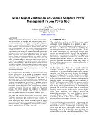
Chip <strong>Design</strong><br />
(Schematic)<br />
Top-Level Floorplanning<br />
Custom Block<br />
<strong>Implementation</strong><br />
Digital Block<br />
<strong>Implementation</strong><br />
Top-Level <strong>Implementation</strong><br />
Chip Assembly and Analysis<br />
Figure 3: The schematic-driven implementation flow<br />
In the schematic-driven flow, top-level floorplanning <strong>for</strong> both analog and digital blocks is typically done in a hierarchical<br />
analog environment such as that provided by the Virtuoso plat<strong>for</strong>m. This floorplanning takes place be<strong>for</strong>e<br />
blocks are implemented. Blocks must be placed to avoid signal integrity problems and to allow sufficient routing<br />
resources. Special care must be taken to properly place sensitive analog blocks that can be impacted by digital<br />
switching noise.<br />
Analog and digital pinout definitions are drawn from the floorplan in a top-down or bottom-up strategy. However,<br />
analog floorplanning is interactive and may be capacity constrained. If there are a large number of pins associated<br />
with a place and route block, a more automated digital floorplanner may be preferred.<br />
After a floorplan is developed, the implementation of individual blocks is handled in the appropriate design<br />
environment. Some blocks may also be pre-designed or purchased IP. The completed analog and digital blocks are<br />
then brought back into the custom design system <strong>for</strong> top-level implementation and chip assembly. Top-level mixed<br />
signal and chip assembly routing can be achieved using the Virtuoso Space-Based Router. Some analysis, however,<br />
may be done in the digital environment, such as static timing analysis during block creation.<br />
One requirement of this flow is an ability to easily handle late-stage ECOs, including custom ECOs from the<br />
schematic and Verilog netlist changes <strong>for</strong> the synthesized digital blocks.<br />
Virtuoso digital implementation<br />
<strong>Solutions</strong> <strong>for</strong> <strong>Mixed</strong>-<strong>Signal</strong> <strong>SoC</strong> <strong>Implementation</strong><br />
To facilitate digital block creation <strong>for</strong> schematic-driven flows, the <strong>Cadence</strong> Virtuoso Digital <strong>Implementation</strong><br />
tool provides a capacity-limited version of the Encounter Digital <strong>Implementation</strong> System. This allows analog/<br />
custom designers to quickly develop digital blocks using an automated, timing-driven digital implementation<br />
flow, and bring them back into the Virtuoso plat<strong>for</strong>m using GDSII, LEF/DEF or OpenAccess. Virtuoso Digital<br />
<strong>Implementation</strong> includes RTL synthesis, silicon virtual prototyping, placement, routing, clock tree synthesis,<br />
extraction, and advanced power planning. The solution can be driven by a script, easing digital implementation<br />
<strong>for</strong> analog designers.<br />
The best way to use Virtuoso Digital <strong>Implementation</strong> is with OpenAccess, an open industry database developed by<br />
<strong>Cadence</strong> that provides much faster and more complete file transfers than LEF/DEF. As shown in Figure 4 below, a<br />
top-level schematic is drawn in Virtuoso, and a digital block is passed to Encounter <strong>for</strong> implementation. It is then<br />
returned to Virtuoso, where chip finishing takes place.<br />
www.cadence.com 5