Solutions for Mixed-Signal SoC Implementation - Cadence Design ...
Solutions for Mixed-Signal SoC Implementation - Cadence Design ...
Solutions for Mixed-Signal SoC Implementation - Cadence Design ...

You also want an ePaper? Increase the reach of your titles
YUMPU automatically turns print PDFs into web optimized ePapers that Google loves.
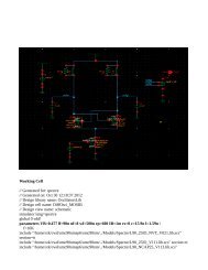
D<br />
A<br />
D<br />
Digital <strong>SoC</strong><br />
A<br />
D<br />
D<br />
A<br />
A<br />
D<br />
A<br />
D<br />
D<br />
D<br />
Analog IP<br />
A<br />
D<br />
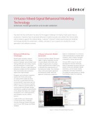
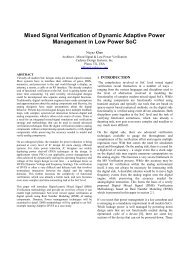
Digital Logic<br />
Figure 1: Digital logic often resides inside analog IP that is integrated into <strong>SoC</strong>s.<br />
<strong>SoC</strong>s must interact with the outside world through displays, antennas, sensors, or other means, and this functionality<br />
is increasingly integrated on-chip. Due to rapidly expanding capacity, a single IP block may represent a complex<br />
mixed-signal function that may have been an entire chip in a previous process generation. Since analog circuitry<br />
doesn’t scale as well as digital, analog/mixed-signal circuitry may take up half the area of an <strong>SoC</strong>.<br />
Today’s physical implementation methodologies are generally either “netlist-driven” flows from a digital cockpit<br />
or “schematic-driven” flows from an analog cockpit. In both cases, these flows were developed to deal with<br />
relatively simple integration challenges. While these methodologies will remain important, <strong>SoC</strong> designers need a<br />
new approach as the amount of complex mixed-signal content grows, and analog and digital circuits become more<br />
functionally coupled.<br />
Under this new approach, analog and digital blocks will be designed concurrently, and will have flexible pin assignments<br />
so they can be placed within a true mixed-signal floorplan. While analog and digital designers will still retain<br />
their own familiar design environments, a common database representation will simplify the integration of analog,<br />
digital and mixed-signal blocks. Responsibility <strong>for</strong> chip assembly and tapeout will be shared. In short, there will be<br />
no hard separation between “analog” and “digital” design.<br />
A Gap Between Divergent Flows Challenges <strong>Mixed</strong>-<strong>Signal</strong> <strong>Implementation</strong><br />
<strong>Solutions</strong> <strong>for</strong> <strong>Mixed</strong>-<strong>Signal</strong> <strong>SoC</strong> <strong>Implementation</strong><br />
<strong>Mixed</strong>-signal <strong>SoC</strong> implementation is a complicated task because it involves two very different design and verification<br />
flows. In a traditional setting, analog and digital blocks are designed by separate teams using entirely<br />
different tools, with little communication between the teams and little understanding of the environment and the<br />
challenges on the other side.<br />
The analog design flow is schematic-driven, with lots of physical hierarchy. While today’s analog/custom design<br />
environments offer some semi-automated features, analog design is traditionally manual and interactive. The<br />
analog flow is largely transistor-based, requiring a level of detail that is mostly hidden on the digital side.<br />
The analog flow typically involves drawing schematics, simulating functionality, drawing or editing polygons to<br />
implement the design, and then executing layout-versus-schematic (LVS) checking to make sure the layout matches<br />
the schematics. In more advanced systems such as the <strong>Cadence</strong> ® Virtuoso ® Layout Suite, the analog flow often<br />
includes the use of parameterized cells (Pcells) and the selective use of automated placement and routing.<br />
The analog flow makes heavy use of physical and electrical constraints. For example, analog layouts may have<br />
constraints related to shielding, differential pairs, matched lengths, and symmetry. Digital floorplanning, placement<br />
and routing systems need to understand these constraints.<br />
The digital design flow, in contrast, is netlist-driven and heavily automated, and uses RTL synthesis—or even<br />
SystemC synthesis—to generate gate-level logic. Aimed at designing ICs with tens or hundreds of millions of gates,<br />
the flow employs cell libraries that hide transistor-level details from the designer. Floorplanning, placement, and<br />
routing are timing-driven and automated.<br />
www.cadence.com 2<br />
D