Solutions for Mixed-Signal SoC Implementation - Cadence Design ...
Solutions for Mixed-Signal SoC Implementation - Cadence Design ...
Solutions for Mixed-Signal SoC Implementation - Cadence Design ...

You also want an ePaper? Increase the reach of your titles
YUMPU automatically turns print PDFs into web optimized ePapers that Google loves.
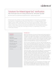
<strong>Solutions</strong> <strong>for</strong> <strong>Mixed</strong>-<strong>Signal</strong> <strong>SoC</strong><br />
<strong>Implementation</strong><br />
By Peter McCrorie, Randolph Fish, and Richard Goering <strong>Cadence</strong> <strong>Design</strong> Systems Inc.<br />
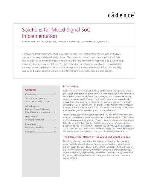
Companies designing mixed-signal <strong>SoC</strong>s are running into several challenges caused by today’s<br />
disjointed analog and digital design flows. This paper discusses current implementation flows<br />
and introduces an emerging integrated mixed-signal implementation methodology in which chip<br />
planning, design, implementation, physical verification, and tapeout are shared responsibilities<br />
between analog and digital teams. <strong>Cadence</strong> supports this new mixed-signal flow that will help<br />
analog and digital designers more efficiently implement complex mixed-signal designs.<br />
Contents<br />
Introduction .................................1<br />
The Hierarchical Nature of<br />
Today’s <strong>Mixed</strong>-<strong>Signal</strong> <strong>Design</strong>s .......1<br />
A Gap Between<br />
Divergent Flows Challenges<br />
<strong>Mixed</strong>-<strong>Signal</strong> <strong>Implementation</strong> .......2<br />
Steps Towards<br />
an Integrated Solution .................3<br />
<strong>Mixed</strong>-<strong>Signal</strong><br />
<strong>Implementation</strong> Flows ..................4<br />
Conclusion ................................. 10<br />
Introduction<br />
Since virtually all systems on chip (<strong>SoC</strong>s) contain some analog circuitry, many<br />
<strong>SoC</strong> design engineers have some familiarity with mixed-signal implementation.<br />
Nevertheless, a new set of challenges is emerging as the amount of analog<br />
circuitry increases, and the use of digital control logic inside analog blocks<br />
grows. These developments are blurring the boundaries between “analog”<br />
and “digital.” Consequently, mixed-signal <strong>SoC</strong> implementation today requires<br />
far more than the traditional practice of importing a few analog “black boxes”<br />
that were designed independently from the digital circuitry.<br />
This paper focuses on advanced mixed-signal <strong>SoC</strong> implementation flows and<br />
solutions. It describes some of the common challenges that result from today’s<br />
disjointed analog and digital design flows. It then discusses current implementation<br />
flows, presents a new flow that allows concurrent analog and digital<br />
design, and notes solutions that support all these flows. A previous <strong>Cadence</strong><br />
white paper discussed mixed-signal design challenges, and a subsequent paper<br />
will discuss the increasingly important topic of mixed-signal verification.<br />
The Hierarchical Nature of Today’s <strong>Mixed</strong>-<strong>Signal</strong> <strong>Design</strong>s<br />
<strong>Mixed</strong>-signal design has become hierarchical, with analog blocks residing<br />
inside digital functions that control analog signals. With the trend towards<br />
digitally assisted analog, devices such as phase-lock loops (PLLs) and analog/<br />
digital converters (ADCs) contain increasing amounts of digital control logic<br />
as well as digital signal processing. Conversely, digital blocks may incorporate<br />
high-speed I/Os and power domain management circuitry with substantial<br />
analog content.
D<br />
A<br />
D<br />
Digital <strong>SoC</strong><br />
A<br />
D<br />
D<br />
A<br />
A<br />
D<br />
A<br />
D<br />
D<br />
D<br />
Analog IP<br />
A<br />
D<br />
Digital Logic<br />
Figure 1: Digital logic often resides inside analog IP that is integrated into <strong>SoC</strong>s.<br />
<strong>SoC</strong>s must interact with the outside world through displays, antennas, sensors, or other means, and this functionality<br />
is increasingly integrated on-chip. Due to rapidly expanding capacity, a single IP block may represent a complex<br />
mixed-signal function that may have been an entire chip in a previous process generation. Since analog circuitry<br />
doesn’t scale as well as digital, analog/mixed-signal circuitry may take up half the area of an <strong>SoC</strong>.<br />
Today’s physical implementation methodologies are generally either “netlist-driven” flows from a digital cockpit<br />
or “schematic-driven” flows from an analog cockpit. In both cases, these flows were developed to deal with<br />
relatively simple integration challenges. While these methodologies will remain important, <strong>SoC</strong> designers need a<br />
new approach as the amount of complex mixed-signal content grows, and analog and digital circuits become more<br />
functionally coupled.<br />
Under this new approach, analog and digital blocks will be designed concurrently, and will have flexible pin assignments<br />
so they can be placed within a true mixed-signal floorplan. While analog and digital designers will still retain<br />
their own familiar design environments, a common database representation will simplify the integration of analog,<br />
digital and mixed-signal blocks. Responsibility <strong>for</strong> chip assembly and tapeout will be shared. In short, there will be<br />
no hard separation between “analog” and “digital” design.<br />
A Gap Between Divergent Flows Challenges <strong>Mixed</strong>-<strong>Signal</strong> <strong>Implementation</strong><br />
<strong>Solutions</strong> <strong>for</strong> <strong>Mixed</strong>-<strong>Signal</strong> <strong>SoC</strong> <strong>Implementation</strong><br />
<strong>Mixed</strong>-signal <strong>SoC</strong> implementation is a complicated task because it involves two very different design and verification<br />
flows. In a traditional setting, analog and digital blocks are designed by separate teams using entirely<br />
different tools, with little communication between the teams and little understanding of the environment and the<br />
challenges on the other side.<br />
The analog design flow is schematic-driven, with lots of physical hierarchy. While today’s analog/custom design<br />
environments offer some semi-automated features, analog design is traditionally manual and interactive. The<br />
analog flow is largely transistor-based, requiring a level of detail that is mostly hidden on the digital side.<br />
The analog flow typically involves drawing schematics, simulating functionality, drawing or editing polygons to<br />
implement the design, and then executing layout-versus-schematic (LVS) checking to make sure the layout matches<br />
the schematics. In more advanced systems such as the <strong>Cadence</strong> ® Virtuoso ® Layout Suite, the analog flow often<br />
includes the use of parameterized cells (Pcells) and the selective use of automated placement and routing.<br />
The analog flow makes heavy use of physical and electrical constraints. For example, analog layouts may have<br />
constraints related to shielding, differential pairs, matched lengths, and symmetry. Digital floorplanning, placement<br />
and routing systems need to understand these constraints.<br />
The digital design flow, in contrast, is netlist-driven and heavily automated, and uses RTL synthesis—or even<br />
SystemC synthesis—to generate gate-level logic. Aimed at designing ICs with tens or hundreds of millions of gates,<br />
the flow employs cell libraries that hide transistor-level details from the designer. Floorplanning, placement, and<br />
routing are timing-driven and automated.<br />
www.cadence.com 2<br />
D
When analog blocks are imported into a largely digital <strong>SoC</strong> design, the blocks are typically black boxes that give<br />
digital designers no visibility into the layouts. The analog blocks typically have fixed guard rings and pinouts. The<br />
hardened IP leads to a lack of flexibility in floorplanning, resulting in a less than optimal floorplan.<br />
The <strong>SoC</strong> integrator has to assume that the analog designer adequately verified the block. It is possible, <strong>for</strong> instance,<br />
to get all the way to design rule checking and find out that a control signal is inverted because the block was never<br />
timed or simulated. Even if all the digital and analog blocks are thoroughly verified at the block level, chip-level<br />
verification across analog and digital interfaces is still very challenging.<br />
Analog designers who import digital blocks face a number of challenges as well. Digital blocks may have pinouts<br />
that are suboptimal in an analog/mixed-signal floorplan. Digital circuitry can cause noise and signal integrity<br />
problems, requiring analog designers to use adequate shielding. Large amounts of simultaneously switching digital<br />
circuitry can cause noise that can get into the substrate and be transmitted throughout the design, resulting in<br />
oscillations and voltage noise in sensitive analog circuitry. Noise can also be transmitted around a chip via the<br />
power routes, the package and the substrate.<br />
The traditional mixed-signal implementation flow results in frequent engineering change orders (ECOs). Analog<br />
and digital design teams may have to go back and <strong>for</strong>th to iteratively change pinouts, floorplans, physical layouts,<br />
and other design attributes to satisfy the constraints and per<strong>for</strong>mance demands of both analog and digital circuitry.<br />
Late-stage ECOs may even <strong>for</strong>ce a redo of chip assembly and chip finishing.<br />
Steps Towards an Integrated Solution<br />
Analog and digital design requirements, methodologies and skill sets are fundamentally different, and design<br />
teams are used to their respective tool environments. A single GUI/interface that handles both analog and digital<br />
design may never be practical, because it <strong>for</strong>ces one, or both, teams away from their proven environment. What<br />
is possible and needed, however, is a planning-to-signoff methodology and solution <strong>for</strong> the design, analysis and<br />
verification of mixed-signal <strong>SoC</strong>s that enables easy and efficient interaction between the analog and digital teams.<br />
The solution needs to support <strong>SoC</strong> integration with large analog, digital and mixed-signal IP blocks.<br />
From a physical implementation perspective, the solution needs to handle system-level design, block-level design,<br />
chip assembly, physical verification, and system verification. Figure 2 shows some of the components of a mixedsignal<br />
implementation system.<br />
System-Level <strong>Design</strong><br />
Block-Level <strong>Design</strong><br />
Chip Assembly<br />
Physical Verification<br />
System Verification<br />
Functional <strong>Design</strong> and Verification<br />
RTL <strong>Design</strong> and<br />
Verification<br />
Synthesis and<br />
Verification<br />
Place and<br />
Route<br />
Chip Planning<br />
DRC, LVS, RCX<br />
Chip Assembly<br />
<strong>Design</strong> and<br />
Analysis<br />
Circuit<br />
Simulation<br />
Custom Layout<br />
Full Chip Physical Verification,<br />
Extraction, and Analysis<br />
Full Chip System-Level Verification<br />
Analog, Digital, RF<br />
Figure 2: Components of a mixed-signal design solution<br />
<strong>Solutions</strong> <strong>for</strong> <strong>Mixed</strong>-<strong>Signal</strong> <strong>SoC</strong> <strong>Implementation</strong><br />
www.cadence.com 3
Some desirable characteristics of a mixed-signal implementation solution include the following:<br />
• The ability of digital designers to “push into” analog blocks and view their layouts<br />
• The ability <strong>for</strong> analog designers to implement digital functionality within their hierarchical floorplan<br />
• A common design database, such as OpenAccess, instead of a more limited layout representation using<br />
LEF/DEF or GDSII file transfers of analog or digital blocks<br />
• A chip planning capability such as the <strong>Cadence</strong> Chip Planning System that allows users to select analog,<br />
digital and mixed/signal IP and obtain early estimates of size, power consumption, per<strong>for</strong>mance and cost<br />
• A common design constraint definition <strong>for</strong> digital and analog, such that constraints developed on either side<br />
can be understood on the other side<br />
• A mixed-signal router that can understand analog constraints such as symmetry and differential pair routing<br />
• Routing solutions that can optimize the routes <strong>for</strong> yield (DFY) objectives<br />
• A capability to extract digital paths in analog blocks <strong>for</strong> static timing analysis, so that analog designers don’t<br />
have to manually build complex .lib files<br />
• The ability <strong>for</strong> analog designers to prevent editing of their sensitive, finely tuned circuits by <strong>SoC</strong> integrators.<br />
• A hierarchical design approach that can manage analog and digital design styles<br />
In addition to meeting specific demands related to mixed-signal integration, a mixed-signal design flow must<br />
provide the per<strong>for</strong>mance and capacity needed <strong>for</strong> today’s extremely large and dense <strong>SoC</strong> designs, and must<br />
meet all the design <strong>for</strong> manufacturability (DFM) requirements of advanced process nodes. It must also support<br />
low-power design <strong>for</strong> both digital and analog IP.<br />
<strong>Mixed</strong>-<strong>Signal</strong> <strong>Implementation</strong> Flows<br />
As previously noted, there are two types of established mixed-signal implementation flows:<br />
• Schematic-driven flows, in which a custom design environment such as the Virtuoso Layout Suite plat<strong>for</strong>m<br />
handles the floorplanning, chip assembly and block integration. Digital blocks are custom designed or imported<br />
from a digital design environment such as <strong>Cadence</strong> Encounter ® Digital <strong>Implementation</strong> system.<br />
• Netlist-driven (Verilog/VHDL) flows, in which the floorplanning, chip assembly and block integration are handled<br />
in a digital design system. Hardened analog IP blocks are imported from an analog/custom design environment<br />
such as the Virtuoso Layout Suite.<br />
Today’s growing and ever-changing mixed-signal requirements demand that these established flows evolve into<br />
flows where floorplanning and chip assembly are shared between the analog and digital design teams, and where<br />
both analog and digital blocks are developed concurrently, requiring extended flexibility in implementation.<br />
The schematic-driven flow<br />
<strong>Solutions</strong> <strong>for</strong> <strong>Mixed</strong>-<strong>Signal</strong> <strong>SoC</strong> <strong>Implementation</strong><br />
This type of flow is driven by schematic entry and makes extensive use of constraints. Custom designers often<br />
draw schematics <strong>for</strong> full-chip block-assembly as well as smaller, hierarchical digital blocks, and may use custom<br />
generators <strong>for</strong> complex datapath and array based modules. For larger digital blocks, an increasing number of<br />
design teams start with Verilog HDL code, making it possible to take advantage of digital synthesis, placement and<br />
routing. The <strong>Cadence</strong> Virtuoso plat<strong>for</strong>m provides a utility that translates a schematic into a Verilog netlist.<br />
A more detailed look at the schematic-driven mixed-signal flow is shown in Fig. 3. Here, the orange coloring<br />
identifies tasks typically done in an analog/custom environment, while blue coloring indicates tasks typically<br />
done in a digital IC design environment.<br />
www.cadence.com 4
Chip <strong>Design</strong><br />
(Schematic)<br />
Top-Level Floorplanning<br />
Custom Block<br />
<strong>Implementation</strong><br />
Digital Block<br />
<strong>Implementation</strong><br />
Top-Level <strong>Implementation</strong><br />
Chip Assembly and Analysis<br />
Figure 3: The schematic-driven implementation flow<br />
In the schematic-driven flow, top-level floorplanning <strong>for</strong> both analog and digital blocks is typically done in a hierarchical<br />
analog environment such as that provided by the Virtuoso plat<strong>for</strong>m. This floorplanning takes place be<strong>for</strong>e<br />
blocks are implemented. Blocks must be placed to avoid signal integrity problems and to allow sufficient routing<br />
resources. Special care must be taken to properly place sensitive analog blocks that can be impacted by digital<br />
switching noise.<br />
Analog and digital pinout definitions are drawn from the floorplan in a top-down or bottom-up strategy. However,<br />
analog floorplanning is interactive and may be capacity constrained. If there are a large number of pins associated<br />
with a place and route block, a more automated digital floorplanner may be preferred.<br />
After a floorplan is developed, the implementation of individual blocks is handled in the appropriate design<br />
environment. Some blocks may also be pre-designed or purchased IP. The completed analog and digital blocks are<br />
then brought back into the custom design system <strong>for</strong> top-level implementation and chip assembly. Top-level mixed<br />
signal and chip assembly routing can be achieved using the Virtuoso Space-Based Router. Some analysis, however,<br />
may be done in the digital environment, such as static timing analysis during block creation.<br />
One requirement of this flow is an ability to easily handle late-stage ECOs, including custom ECOs from the<br />
schematic and Verilog netlist changes <strong>for</strong> the synthesized digital blocks.<br />
Virtuoso digital implementation<br />
<strong>Solutions</strong> <strong>for</strong> <strong>Mixed</strong>-<strong>Signal</strong> <strong>SoC</strong> <strong>Implementation</strong><br />
To facilitate digital block creation <strong>for</strong> schematic-driven flows, the <strong>Cadence</strong> Virtuoso Digital <strong>Implementation</strong><br />
tool provides a capacity-limited version of the Encounter Digital <strong>Implementation</strong> System. This allows analog/<br />
custom designers to quickly develop digital blocks using an automated, timing-driven digital implementation<br />
flow, and bring them back into the Virtuoso plat<strong>for</strong>m using GDSII, LEF/DEF or OpenAccess. Virtuoso Digital<br />
<strong>Implementation</strong> includes RTL synthesis, silicon virtual prototyping, placement, routing, clock tree synthesis,<br />
extraction, and advanced power planning. The solution can be driven by a script, easing digital implementation<br />
<strong>for</strong> analog designers.<br />
The best way to use Virtuoso Digital <strong>Implementation</strong> is with OpenAccess, an open industry database developed by<br />
<strong>Cadence</strong> that provides much faster and more complete file transfers than LEF/DEF. As shown in Figure 4 below, a<br />
top-level schematic is drawn in Virtuoso, and a digital block is passed to Encounter <strong>for</strong> implementation. It is then<br />
returned to Virtuoso, where chip finishing takes place.<br />
www.cadence.com 5
VIRTUOSO<br />
Netlist-driven flow<br />
Draw Top Level<br />
Chip Finishing<br />
OPEN ACCESS<br />
<strong>Design</strong> Library Constraints<br />
Synthesis using RTL Compiler<br />
<strong>Implementation</strong> in Encounter<br />
Placement<br />
Optimization preCTS<br />
Clock Tree Synthesis<br />
Optimization postCTS<br />
Routing<br />
Add Filler cells<br />
Verification<br />
Figure 4: By sharing the OpenAccess database, Virtuoso and Encounter<br />
users can rapidly transfer analog and digital blocks back and <strong>for</strong>th.<br />
The netlist-driven flow takes place primarily within a timing-driven digital design environment (Figure 5). It typically<br />
uses hardened analog IP designed by an analog design group or third-party provider. The layout <strong>for</strong> the analog IP<br />
is completed, the pinouts are typically fixed, and guard rings are locked into place using the Virtuoso Layout Suite.<br />
This may take place be<strong>for</strong>e any digital design has begun.<br />
Custom IP Block <strong>Implementation</strong><br />
Chip <strong>Design</strong> (Verilog)<br />
Prototyping<br />
Digital <strong>Implementation</strong><br />
Top-Level <strong>Implementation</strong><br />
Chip Assembly and Analysis<br />
Figure 5: Netlist-driven implementation flow<br />
<strong>Solutions</strong> <strong>for</strong> <strong>Mixed</strong>-<strong>Signal</strong> <strong>SoC</strong> <strong>Implementation</strong><br />
www.cadence.com 6<br />
ENCOUNTER
Floorplanning and prototyping precede detailed digital implementation. In the Encounter Digital <strong>Implementation</strong><br />
system, chip prototyping provides a very rapid full-chip representation that allows users to improve their floorplan<br />
<strong>for</strong> congestion and timing. While not “DRC clean,” the prototype provides a high level of confidence that the<br />
design and floorplan won’t cause top-level implementation and timing closure problems later.<br />
After analog blocks are imported, and digital blocks are imported or created, top-level implementation takes<br />
place in the digital environment. Analog blocks may have specific area or aspect ratio requirements that must be<br />
met. Chip assembly and analysis mostly take place in the digital environment, although some of the verification,<br />
extraction and analysis may take place on the analog side. <strong>SoC</strong> signoff requires static timing, signal integrity,<br />
and IR drop analyses, and the integrator must ensure that any additions or fixes don’t negatively impact analog/<br />
digital interfaces.<br />
The <strong>Cadence</strong> Virtuoso and Encounter plat<strong>for</strong>ms support a single design database on OpenAccess, greatly simplifying<br />
the transfer of analog blocks to and from the Virtuoso environment. Physical design data, hierarchical netlists,<br />
and mixed-signal routing constraints can all be saved with OpenAccess.<br />
Encounter mixed signal GXL option<br />
In the <strong>Cadence</strong> flow, the Encounter <strong>Mixed</strong> <strong>Signal</strong> GXL option provides enhanced support <strong>for</strong> netlist-driven mixedsignal<br />
flows. With the <strong>Mixed</strong> <strong>Signal</strong> GXL option, digital designers using Encounter have full visibility into Pcell<br />
layouts <strong>for</strong> analog IP blocks (Figure 6). Guard rings, however, can be frozen when editing. Additionally, a mixedsignal<br />
routing capability manages analog constraints such as shielding, matching, differential pairs, and bus routing<br />
while still providing high-speed digital routing.<br />
Substrate analysis<br />
Implement custom design, add<br />
guard rings and pCells<br />
D<br />
A<br />
Digital<br />
Sea-of-Cells<br />
P<br />
P<br />
Analog<br />
D<br />
A<br />
Easy, round-trip<br />
data transfers<br />
Virtuoso Encounter<br />
Open Access<br />
Load design into digital environment,<br />
guard rings edit locked, pCells fully<br />
visible, ECO sees all non-P&R objects<br />
D<br />
A<br />
Digital<br />
Sea-of-Cells<br />
P<br />
P<br />
Analog<br />
Figure 6: OpenAccess eases the integration of analog IP into mostly digital <strong>SoC</strong> designs.<br />
<strong>Solutions</strong> <strong>for</strong> <strong>Mixed</strong>-<strong>Signal</strong> <strong>SoC</strong> <strong>Implementation</strong><br />
<strong>Mixed</strong>-signal designs raise the risk of chip malfunction due to coupling through the substrate. One way or another,<br />
designers must predict and minimize substrate noise. Full-chip substrate analysis is an emerging capability that<br />
can help designers determine where guard rings are required, and whether spacing is sufficient to avoid substrate<br />
noise. The analysis should identify digital noise sources caused by simultaneous switching, model noise transmission<br />
through the substrate, and report the impact of digital noise on sensitive analog components.<br />
Without substrate noise analysis, a conservative approach that makes heavy use of guard rings or employs a triplewell<br />
silicon process may be required, leading to additional area, cost, and the possibility of additional coupling.<br />
www.cadence.com 7<br />
D<br />
A
Digital timing verification<br />
The verification of digital timing paths inside mixed-signal blocks is problematic in traditional netlist-driven flows.<br />
Typically, digital implementation tools extract path parasitics only to the analog IP block’s instance pin, and any<br />
loading inside the block is modeled by a .lib file (Figure 7, left). Generating that .lib file amounts to a generally<br />
painful experience <strong>for</strong> analog designers.<br />
A better approach provided by the Encounter Digital <strong>Implementation</strong> system involves extracting full-path parasitics<br />
all the way to the digital instance pin (Figure 7, right). The tool models the loading of the digital path inside a<br />
mixed-signal block as a distributed RC network. Internal loading is thus appended to the extracted path, and<br />
static timing analysis can verify the complete path with no need to generate a .lib file.<br />
Digital<br />
I1 I2<br />
Path parasitics<br />
extracted to<br />
AMS instance pin<br />
Digital cell library instances<br />
AMS AMS Partition .lib<br />
Towards a new mixed-signal implementation flow<br />
Digital<br />
I1<br />
Extract full path<br />
parasitics to digital<br />
instance pin<br />
Figure 7: Extracting full-path parasitics allows timing closure on<br />
mixed-signal blocks without requiring generation of a .lib file.<br />
<strong>Solutions</strong> <strong>for</strong> <strong>Mixed</strong>-<strong>Signal</strong> <strong>SoC</strong> <strong>Implementation</strong><br />
I2<br />
AMS Partition<br />
The schematic-driven and netlist-driven flows are block-based approaches that involve the import of one type of<br />
block into a larger analog or digital environment. The emerging mixed-signal flow represents a much more integrated<br />
methodology. While the new flow retains separate analog and digital design teams and tools, responsibility <strong>for</strong> the<br />
overall design, verification and chip tapeout is shared.<br />
One big advance with this new approach is that analog and digital blocks can be designed concurrently. Floorplanning<br />
can be truly mixed-signal, with flexibility to assign or optimize pins. With flexible pinouts, designers do not need to<br />
send analog or digital blocks back <strong>for</strong> rework if they find that fixed pinouts don’t work in a floorplan. Results can include<br />
earlier floorplanning, smaller area, less routing congestion, earlier chip finishing, and faster overall turn-around times.<br />
Figure 8 shows an advanced mixed-signal implementation flow. Notice how the top-level floorplan becomes a joint<br />
exercise between analog and digital design groups. These teams concurrently optimize the floorplan, changing<br />
pinouts and locations and routing nets as needed, until they can both sign off on the floorplan. Each team must be<br />
aware of the constraints on the other side.<br />
www.cadence.com 8
Chip <strong>Design</strong><br />
(Schematic/Netlist)<br />
Top-Level Floorplanning<br />
Custom Block<br />
<strong>Implementation</strong><br />
Digital Block<br />
<strong>Implementation</strong><br />
Top-Level <strong>Implementation</strong><br />
Chip Assembly and Analysis<br />
Figure 8: Advanced mixed-signal implementation flow<br />
Once the floorplan is completed, custom and digital block implementation then follow in separate analog and<br />
digital environments. Some blocks may also be imported as pre-existing or purchased IP. Top-level implementation,<br />
like floorplanning, becomes a shared exercise between analog and digital teams, with necessary readjustments<br />
made on either side. Chip assembly and analysis are shared as well.<br />
The <strong>Cadence</strong> environment provides support <strong>for</strong> an integrated mixed-signal flow. Top-level floorplanning and<br />
prototyping are typically completed in Encounter, which offers automated capabilities. <strong>Design</strong> partitioning from<br />
floorplanning enables concurrent analog/digital block design and optimization. Digital logic is implemented<br />
in Encounter, and analog blocks are implemented in Virtuoso. Chip assembly and full-chip signoff analysis are<br />
typically completed in Encounter.<br />
The fast data transfers enabled by the shared OpenAccess database make this type of flow possible. Instead of<br />
slow, incomplete LEF/DEF transfers of black boxes, analog and digital designers can quickly view and manipulate<br />
analog and digital blocks. But analog designers can still “lock” features such as guard rings to protect them from<br />
unwanted editing.<br />
Other important characteristics of the advanced mixed-signal flow supported by <strong>Cadence</strong> technology include:<br />
• The ability <strong>for</strong> the mixed-signal router to understand analog routing constraints<br />
• The ability to view the complete design in a digital environment<br />
• Improved pin optimization <strong>for</strong> analog and digital blocks<br />
• Use of manual/interactive and automated hierarchical floorplanning <strong>for</strong> analog and digital circuitry<br />
• Seamless data transfer between analog and digital designers<br />
• The ability to mix digital and analog circuitry in the same area without hierarchy constraints<br />
• ECOs that can be implemented in either environment<br />
• Digital timing closure that covers all digital logic and paths<br />
• Late-stage ECOs on digital blocks that don’t disrupt chip-finishing details<br />
<strong>Solutions</strong> <strong>for</strong> <strong>Mixed</strong>-<strong>Signal</strong> <strong>SoC</strong> <strong>Implementation</strong><br />
• Chip assembly routing with support <strong>for</strong> complex analog requirements as well as high-capacity digital needs<br />
www.cadence.com 9
Conclusion<br />
<strong>Solutions</strong> <strong>for</strong> <strong>Mixed</strong>-<strong>Signal</strong> <strong>SoC</strong> <strong>Implementation</strong><br />
As lower process nodes allow bigger and denser chips—enabling designers to pack more and more functionality<br />
onto a single chip—<strong>SoC</strong> implementation is becoming increasingly difficult. Additionally, today’s <strong>SoC</strong> designs<br />
include more analog blocks, and a growing number of blocks have both analog and digital circuitry and are thus<br />
truly mixed-signal.<br />
Historically, mixed-signal implementation methodologies involved the import of hardened analog blocks onto a<br />
digital chip, or small amounts of digital logic into analog blocks or ICs. Analog and digital designers often worked<br />
in isolation with little understanding of the challenges and constraints on the other side. The net result was an<br />
ECO-driven flow in which pinouts, floorplans, placement and routing, and tapeouts went through a number of<br />
iterations to produce a working chip.<br />
Still, the existing schematic-driven and netlist-driven implementation flows remain important, and they can be<br />
optimized and improved with a well thought-out methodology that includes a top-level floorplan, analog/digital<br />
block implementation, top-level implementation, and chip assembly and analysis. A common database representation<br />
can greatly ease these flows. Features such as mixed-signal routing, visibility into analog blocks, and<br />
extraction of digital timing paths also aid designers in overcoming <strong>SoC</strong> challenges.<br />
The solution that’s emerging now is an integrated mixed-signal implementation methodology in which chip<br />
planning, design, implementation, physical verification, and tapeout are shared responsibilities between analog<br />
and digital teams. Analog and digital blocks can be concurrently designed, and floorplanning can be a shared<br />
exercise. This type of flow makes use of the OpenAccess database to provide quick access to all design data by<br />
both analog and digital teams. It also leverages the strengths of existing analog and digital design environments,<br />
using capabilities from each where appropriate.<br />
The new mixed-signal flow supported by <strong>Cadence</strong> will help both analog and digital designers more efficiently<br />
implement complex mixed-signal designs.<br />
<strong>Cadence</strong> is trans<strong>for</strong>ming the global electronics industry through a vision called EDA360.<br />
With an application-driven approach to design, our software, hardware, IP, and services help<br />
customers realize silicon, <strong>SoC</strong>s, and complete systems efficiently and profitably. www.cadence.com<br />
©2011 <strong>Cadence</strong> <strong>Design</strong> Systems, Inc. All rights reserved. <strong>Cadence</strong> and the <strong>Cadence</strong> logo are registered trademarks of <strong>Cadence</strong> <strong>Design</strong> Systems, Inc.,<br />
All rights reserved. <strong>Cadence</strong> and the <strong>Cadence</strong> logo are registered trademarks of <strong>Cadence</strong> <strong>Design</strong> Systems, Inc., All rights reserved. <strong>Cadence</strong> and the<br />
<strong>Cadence</strong> logo are registered trademarks of <strong>Cadence</strong> <strong>Design</strong> Systems, Inc. 21248 12/11 RG/DM/PDF