DVCON-2010-MS Verification of Dynamic - Cadence Design Systems
DVCON-2010-MS Verification of Dynamic - Cadence Design Systems
DVCON-2010-MS Verification of Dynamic - Cadence Design Systems

Create successful ePaper yourself
Turn your PDF publications into a flip-book with our unique Google optimized e-Paper software.
Mixed Signal <strong>Verification</strong> <strong>of</strong> <strong>Dynamic</strong> Adaptive Power<br />
Management in Low Power SoC<br />
ABSTRACT<br />
Virtually all modern SoC designs today are mixed-signal in nature.<br />
Most systems have to interface their millions <strong>of</strong> gates, DSPs,<br />
memories, and processors to the real world through a display, an<br />
antenna, a sensor, a cable or an RF interface. The already complex<br />
task <strong>of</strong> functional verification at the SoC level is getting harder and<br />
more time consuming. Up until recently, mixed-signal designs<br />
could be decomposed into separate analog and digital functions.<br />
Traditionally, digital verification engineers have made assumptions<br />
and approximations about the analog components and likewise, the<br />
analog designers have made assumptions about the digital<br />
behavior. Present day mixed-signal designs have multiple feedback<br />
loops with complex system-level interaction between digital and<br />
analog components, which is <strong>of</strong>ten a rich source <strong>of</strong> errors. There is<br />
a need for an integrated mixed-signal simulation and verification<br />
strategy and methodology that can be used to extend advanced<br />
verification techniques from the digital verification realm to analog<br />
components without compromising speeds needed to verify digital<br />
components while preserving the accuracy needed to model and<br />
verify analog components.<br />
On an orthogonal plane, the mandate for power reduction is being<br />
pursued at every level <strong>of</strong> IC design for more energy efficient<br />
systems. For static power reduction, IC designers are widely<br />
deploying power shut-<strong>of</strong>f (PSO) techniques in the design. In<br />
applications where PSO is not applicable, power management is<br />
<strong>of</strong>ten achieved by dynamically scaling the operating frequency and<br />
voltage <strong>of</strong> the target design in real time – a technique know as<br />
DVFS (<strong>Dynamic</strong> Voltage and Frequency Scaling). The verification<br />
<strong>of</strong> DVFS is <strong>of</strong>ten a very difficult and delicate task that involves<br />
tremendous interaction between the digital and the analog<br />
domains. This further increases the complexity <strong>of</strong> functional<br />
verification, which was already a bottle neck, and now becomes<br />
even more complex and time-consuming task at the SoC level.<br />
This paper will introduce Digital-centric Mixed Signal (D<strong>MS</strong>)<br />
<strong>Verification</strong> methodology and provide an overview <strong>of</strong> how it can<br />
enable high performance SoC-level mixed signal verification at<br />
digital speeds using Real Number Modeling (RNM) <strong>of</strong> analog<br />
components. <strong>Dynamic</strong> Power management techniques will be<br />
examined in detail. D<strong>MS</strong> methodology will be applied to an SoC<br />
example running Adaptive DVFS as a case study.<br />
Neyaz Khan<br />
Architect - Mixed Signal & Low Power <strong>Verification</strong><br />
<strong>Cadence</strong> <strong>Design</strong> <strong>Systems</strong>, Inc.<br />
Plano, TX, USA<br />
nkhan@cadence.com<br />
1 INTRODUCTION<br />
The complexities involved in SoC level mixed signal<br />
verification reveal themselves in a number <strong>of</strong> ways –<br />
ranging from the various languages and disciplines used to<br />
the level <strong>of</strong> abstraction involved in modeling the<br />
functionality <strong>of</strong> complex modern mixed signal SoCs. While<br />
the analog components are functionally verified using<br />
transient analysis and typically use tools that are based on<br />
sparse-matrix based numerical methods, on the digital side<br />
functionality is verified using event driven simulation. Both<br />
disciplines come together at the SoC level and the task <strong>of</strong><br />
verifying functional correctness, which was already a<br />
daunting task, now gets even more complex and needless to<br />
say, much more difficult.<br />
On the digital side, there are advanced verification<br />
techniques available to gauge the thoroughness and<br />
completeness <strong>of</strong> the verification effort and require multiple<br />
regression runs. With that comes the need for simulation<br />
speed and throughput. On the analog side, there is a need for<br />
a high-level <strong>of</strong> accuracy – a single event like a clock edge<br />
on the digital side may require numerous computations on<br />
the analog engine. This becomes a very severe bottleneck in<br />
the <strong>MS</strong> <strong>Verification</strong> process. While this accuracy may be<br />
required for verification within the analog environment<br />
itself, it may not always be necessary for interacting with<br />
the digital side. A desirable solution would be to move high<br />
frequency events from the analog engine onto the digital<br />
engine while preserving the accuracy needed for<br />
analog/digital interaction. This forms the basis <strong>of</strong> a newly<br />
proposed Digital Mixed Signal (D<strong>MS</strong>) <strong>Verification</strong><br />
Methodology based on Real Number Modeling (RNM)<br />
which is presented in this paper in section 2.1.<br />
It’s no secret that power management is a key careabout and<br />
is emerging as a mandatory requirement in all modern SoCs.<br />
While leakage power is well managed by powering down<br />
design units that are not functionally needed during the<br />
operational cycle <strong>of</strong> a device [8], there are some key<br />
sections <strong>of</strong> the device that can not be powered down. These
are <strong>of</strong>ten very power hungry and need to be addressed.<br />
<strong>Dynamic</strong> power management is a very delicate task<br />
whereby the operating voltage and frequency are modulated<br />
based on processing needs – see section 3.1. This requires a<br />
lot <strong>of</strong> very complex interaction between the analog and<br />
digital components to orchestrate dynamic power<br />
management at the SoC level. Needless to say, this is a very<br />
difficult task to verify on a digital simulator – so far in the<br />
industry there is very little support to verify dynamic power<br />
management. This paper addresses the verification <strong>of</strong><br />
Adaptive <strong>Dynamic</strong> Voltage and Frequency Scaling (DV FS)<br />
as an application <strong>of</strong> the proposed D<strong>MS</strong> <strong>Verification</strong><br />
methodology. See section 5 for details.<br />
This paper will first introduce and propose a D<strong>MS</strong><br />
<strong>Verification</strong> Methodology – section 2.2, followed by an<br />
introduction to the concept <strong>of</strong> dynamic power management<br />
– section 3.1. It will then apply D<strong>MS</strong> methodology to an<br />
SoC example for verifying Adaptive DVFS – section 5.<br />
2 DIGITAL MIXED SIGNAL<br />
VERIFICATION<br />
Digital Mixed Signal (D<strong>MS</strong>) methodology is based on the<br />
use <strong>of</strong> Real Number Modeling (RNM) to model analog<br />
components at the SoC level. With the help <strong>of</strong> RNM, users<br />
can perform verification <strong>of</strong> their analog or mixed-signal<br />
designs using discretely simulated real numbers that<br />
involves using only the digital solver. By avoiding<br />
traditional, slower analog simulation, intensive verification<br />
<strong>of</strong> mixed signal design can be performed in short period <strong>of</strong><br />
time.<br />
To meet the verification goals, certain amount <strong>of</strong> simulation<br />
data and data accuracy are required, e.g. a detailed analysis<br />
<strong>of</strong> an RF low noise amplifier requires very high simulation<br />
accuracy but a single RF sinusoid period might be<br />
sufficient. On the other hand, a pin connectivity check for a<br />
large digital block has an extremely low sensitivity towards<br />
accuracy but may require a long transient simulation time to<br />
cover all sorts <strong>of</strong> events and states.<br />
Consequently, a long full-chip simulation run using highest<br />
level <strong>of</strong> simulation accuracy would be desirable. The<br />
limiting factor in this context is simulation performance.<br />
The only practical way around this problem is a hierarchical<br />
verification approach that uses different level <strong>of</strong> design<br />
abstractions for different verification goals. Real numbers<br />
modeling is an interesting add-on to classical mixed signal<br />
verification approaches, like a Verilog and Spice mixed<br />
signal simulation or a pure digital modeling <strong>of</strong> the analog<br />
block in the mixed signal design. The extremely high<br />
accuracy <strong>of</strong> traditional analog simulation is traded <strong>of</strong>f for<br />
speed while still preserving enough accuracy to enable<br />
highly accurate interaction between digital and analog<br />
domain that is required for a full SoC level simulation.<br />
The target audiences for D<strong>MS</strong> are analog, digital as well as<br />
mixed signal engineers seeking high performance mixed<br />
signal verification with the ability to:<br />
• Perform high volume, digital-centric nightly<br />
regressions tests to verify their mixed signal SoCs<br />
• Verifying Top-level SoCs that have a small to<br />
moderate amount <strong>of</strong> analog in the design<br />
RNM also opens the possibility <strong>of</strong> linkage with other<br />
advanced verification techniques such as metrics driven and<br />
assertion-based verification without the difficulty <strong>of</strong><br />
interfacing to the analog engine or defining new semantics<br />
to deal with analog values.<br />
2.1 Real Number Modeling (RNM) for Digital<br />
Mixed Signal Simulation<br />
The simulation approaches in analog and digital are<br />
fundamentally different due to the structure <strong>of</strong> the<br />
underlying equation system to solve. While the digital<br />
solver is solving logical expressions in a sequential manner<br />
based on triggering events, the analog simulator must solve<br />
the entire analog system matrix at every simulation step.<br />
Each element in the analog design can have an<br />
instantaneous influence on any other element in the matrix<br />
and vice versa. Thus, there is not an obvious signal flow in<br />
one or the other direction. Time and values are continuous.<br />
In digital, time and values are discrete. The solver can apply<br />
a well-defined scheme <strong>of</strong> signal flow and events to solve the<br />
system. RNM is a mixed approach borrowing concepts from<br />
both domains. The values are modeled as continuous –<br />
floating-point (real) numbers to emulate the analog world.<br />
However, time is discrete, meaning the real signals change<br />
values based on discrete events. In this approach, we apply<br />
the signal flow concept, so that the digital engine is able to<br />
solve the RNM system without support <strong>of</strong> the analog solver.<br />
This guarantees a high simulation performance that is in the<br />
range <strong>of</strong> a normal digital simulation and orders <strong>of</strong><br />
magnitudes higher than the analog simulation speed.<br />
Real number modeling capabilities are supported in<br />
different standard HDL languages (ref. [7] for details):<br />
• wreal ports in Verilog-A<strong>MS</strong><br />
• real in VHDL<br />
• real in SystemVerilog<br />
It is important to note that the real-wire (wreal) is defined<br />
only in the Verilog-A<strong>MS</strong> LRM. Thus, a wreal can only be<br />
used in a Verilog-A<strong>MS</strong> block. However, it is the digital<br />
kernel only that solves the wreal system. There are no major<br />
performance drawbacks when using these types <strong>of</strong> Verilog-<br />
A<strong>MS</strong> modules in a digital simulation context.
A detailed understanding <strong>of</strong> the reference design – in most<br />
cases the transistor level circuit – is required for the model<br />
creation process. This includes transistor level simulations<br />
that are mostly driven from the simulation environment<br />
(ADE). Verilog-A models are also frequently used. On the<br />
other hand, the model is created for a specific verification<br />
purpose with its performance and accuracy requirements.<br />
While analog designers mainly own the first skill set, the<br />
mixed signal verification engineers understand the<br />
verification requirements better. Therefore, a close<br />
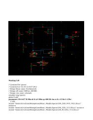
cooperation between both parties is needed. Figure 1 shows<br />
a simple example <strong>of</strong> RNM using Verilog-A<strong>MS</strong> wreals.<br />
Figure 1: Example <strong>of</strong> RNM using Verilog-A<strong>MS</strong> wreals<br />
2.2 SoC level D<strong>MS</strong> <strong>Verification</strong> Flow<br />
The typical SoC <strong>Verification</strong> flow involves top-level<br />
simulation <strong>of</strong> components at various levels <strong>of</strong> abstraction.<br />
For example, a verification engineer may need to integrate<br />
components from schematics, SystemVerilog, and Verilog<br />
(or VHDL)-A<strong>MS</strong> in a single top-level SoC verification.<br />
Figure 2 illustrates a typical <strong>MS</strong> SoC <strong>Verification</strong> Env (VE).<br />
Figure 2: Methodology Stage 1 – Traditional <strong>MS</strong>-SoC top-level<br />
simulation env.<br />
Functional complexity from the analog domain in terms <strong>of</strong><br />
modes <strong>of</strong> operation, extensive digital calibration, and<br />
architectural algorithms can overwhelm the traditional<br />
digital verification methodologies and flow. Simulation at<br />
this top-level is extremely costly – both in terms <strong>of</strong> time and<br />
licenses cost, since a significant amount <strong>of</strong> simulation time<br />
for the SoC is spent in the analog engine. Finding a way to<br />
reduce the time and expense to verify this SoC, while<br />
trading <strong>of</strong>f some accuracy that is not needed at this high<br />
level <strong>of</strong> integration, is extremely valuable. This is the target<br />
application <strong>of</strong> Real Number Modeling. By replacing the<br />
analog portions <strong>of</strong> the SoC with functionally equivalent<br />
digital models, which do not require the analog engine, we<br />
achieve a significant speed-up in simulation performance.<br />
Meanwhile, typical analog simulation problems such as<br />
convergence issues are totally eliminated. Figure 3 is a<br />
modified version <strong>of</strong> the above picture with the analog<br />
portions <strong>of</strong> the design replaced with functionally equivalent<br />
real Number models.
Figure 3: Methodology Stage 2 – D<strong>MS</strong>-SoC top-level<br />
simulation env using RV-Models<br />
It is important to note that this top level verification strategy<br />
illustrated in Figure 3, is not a replacement for detailed<br />
block or multiple-block, cluster-level verification with full<br />
analog simulation accuracy.<br />
The gain in simulation performance and the reduction in<br />
accuracy are highly dependent on the application. There is<br />
no general recommendation on what level <strong>of</strong> abstraction<br />
might be useful or not. There are significant advantages <strong>of</strong><br />
each – simulation speed vs. accuracy must be carefully<br />
traded <strong>of</strong>f based on the target application. At the SoC-level<br />
verification, there might be rare cases where the RNM based<br />
approach does not provide enough accuracy for a particular<br />
verification goal, e.g. cross talk <strong>of</strong> a global net into an<br />
analog sub block. In such a case, there is a need to replace<br />
RNM models with more detailed analog models –<br />
spice/Verilog-A. In the D<strong>MS</strong> based flow, this can be<br />
supported fully as seen in Figure 4, since the RNM models<br />
are pin compatible with the more detailed analog models.<br />
Other enhancements in the testbench, like coercion <strong>of</strong> wreal<br />
types eliminate the need for any modifications in the VE<br />
when swapping analog models with different levels <strong>of</strong><br />
abstraction. Hence, models coded in wreals, Verilog-A,<br />
Verilog-A<strong>MS</strong>, VHDL-A<strong>MS</strong>, VHDL-A, Spice can be<br />
swapped as needed in the testbench as shown in Figure 4.<br />
Figure 4: Methodology Stage 3 – D<strong>MS</strong>-SoC top-level mixed<br />
simulation env using RV-Models & detailed analog models<br />
Also note that the model verification task – comparing the<br />
model against the transistor level reference for each RNM<br />
model used in the top-level verification is essential to<br />
qualify the overall verification result. This is illustrated in<br />
Figure 5, but is beyond the scope <strong>of</strong> current paper.<br />
Figure 5: Functional Validation <strong>of</strong> RV-Models<br />
3 POWER MANAGEMENT<br />
There are two main sources <strong>of</strong> power dissipation in any<br />
CMOS based design - dynamic power is dissipated only<br />
when switching, leakage current is permanent and results in a<br />
continuous loss [9]<br />
Power = Pswitching+Pshort-circuit+Pleakage+Pstatic [Eq 1]<br />
Pswitching = a .f.Ceff .Vdd 2 [Eq 2]
Where a = switching activity, f = clock-freq, Ceff = effective<br />
capacitance & Vdd = supply voltage<br />
Leakage power is well managed by powering down parts <strong>of</strong><br />
the design when not in use. This problem is well understood<br />
in the industry and power aware simulations supported by<br />
using either Common Power Format (CPF), [8], or Unified<br />
Power Format (UPF), [5].<br />
<strong>Dynamic</strong> power can be lowered by reducing switching<br />
activity and clock frequency which effects performance, and<br />
also by reducing capacitance and supply voltage.<br />
3.1 <strong>Dynamic</strong> Power reduction – DVFS<br />
One <strong>of</strong> the primary techniques used in the industry for<br />
dynamic power reduction is DVFS – <strong>Dynamic</strong> Voltage and<br />
Frequency Scaling [11] which consists primarily <strong>of</strong> reducing<br />
the frequency & voltage <strong>of</strong> a design – see Figure 6.<br />
The scaling <strong>of</strong> voltage and frequency is performed in realtime,<br />
based on processing needs <strong>of</strong> the device with the goal<br />
<strong>of</strong> being able to run at the lowest possible frequency and<br />
voltage that will support the requirements <strong>of</strong> the target<br />
application.<br />
Figure 6: <strong>Dynamic</strong> Power Management - DVFS<br />
DVFS is used for both:<br />
• Power-saving during <strong>of</strong>f peak processing times,<br />
and<br />
• As a protective measure to avoid over heating<br />
3.1.1 Voltage Scaling – Open Loop vs. Adaptive DVFS<br />
Open-loop DVFS is the most commonly used form <strong>of</strong><br />
DVFS. The operating voltage point or nominal-voltage is<br />
pre-determined for the target application and desired<br />
operating frequency. The aim is to run the device at the<br />
lowest possible voltage while achieving desired<br />
performance. The actual clock speed <strong>of</strong> the device is<br />
determined by the PVT (Process, operating Voltage &<br />
junction Temperature). The desired clock-speed is achieved<br />
by scaling the voltage to the desired clock-frequency based<br />
on statistical data for that process. The operating voltage<br />
point for each target frequency is typically stored in look-up<br />
tables and used by the power-controller to scale voltage up<br />
and down as needed by the application as shown in Figure<br />
7.<br />
Figure 7: Open-Loop Voltage Scaling<br />
For safety reasons, there are typically large margins<br />
assigned to the operating voltage points for each target<br />
frequency in the look-up table for open-looped voltage<br />
scaling. To achieve the maximum power saving, there is a<br />
need to scale the voltages with a much finer granularity.<br />
Since the actual operating speed also changes with junction<br />
temperature (PVT), there is a constant need to scale voltage<br />
to reach optimal power reduction. This is achieved by<br />
introducing a feedback loop to the power controller which<br />
indicates how fast, or slow a device is actually running<br />
based on PVT characteristics. As shown in Figure 8, this<br />
task is facilitated by the Hardware Performance Monitor<br />
(HPM) which enables closed loop voltage scaling.<br />
Figure 8: Closed Loop Voltage Scaling<br />
In this paper, closed loop voltage scaling will be simulated<br />
using wreal models <strong>of</strong> the LDO and HPM and frequency
scaling is simulated using wreal models <strong>of</strong> the VCO. This is<br />
described in detail in section 5.4 and section 5.2 .<br />
4 D<strong>MS</strong> VERIFICATION METHODOLOGY<br />
4.1 <strong>Verification</strong> Planning<br />
<strong>Verification</strong> planning is the process <strong>of</strong> using the spec to<br />
define what to check, not looking at the design and defining<br />
how to check. By planning what to check, you make sure<br />
that you cover all the features that are expected at the SoC<br />
level and not just what you’ve designed into the block. This<br />
is a major failure area in <strong>MS</strong> SoCs in that the analog block is<br />
verified under different conditions at the SoC level than were<br />
verified at the block level.<br />
<strong>Verification</strong> planning is one <strong>of</strong> the key steps to managing<br />
the complexities involved in the D<strong>MS</strong> verification flow.<br />
First, it is critical to get all relevant design, verification and<br />
implementation teams to agree to what the key low power<br />
features and use cases are, and how to verify that they are<br />
operating correctly. This translates into the generation <strong>of</strong><br />
both the system and block level verification environments.<br />
These environments need to ensure that they verify all the<br />
defined use cases. This translates into coverage, assertion<br />
based checking, score-boarding as well as the actual<br />
generation <strong>of</strong> appropriate stimuli for both digital and analog<br />
components.<br />
Planning for <strong>MS</strong> needs to ensure that all the relevant analog<br />
components are verified with the well defined and legal<br />
operating parameters and operations exercised correctly and<br />
thoroughly in the context <strong>of</strong> D<strong>MS</strong> <strong>Verification</strong>. It needs to<br />
define the proper modes and the requirements that must be<br />
met for each operating mode and transition between modes.<br />
Further, it needs to define the exact set <strong>of</strong> features that need<br />
to be verified in each <strong>of</strong> the designs operating modes.<br />
Figure 9: Metrics Driven <strong>Verification</strong> for <strong>MS</strong> SoC<br />
The planning process is always important for verification,<br />
but for <strong>MS</strong> it becomes critical. The sheer range <strong>of</strong> operating<br />
parameters and complex interaction <strong>of</strong> Analog/Digital units<br />
requires a clear definition <strong>of</strong> relevant metrics defined and<br />
measured for both Analog & Digital design units – Figure 9.<br />
There is a need for a clear definition <strong>of</strong> what verification<br />
closure means in the context <strong>of</strong> <strong>MS</strong> operation <strong>of</strong> the device<br />
in the verification plan. This is particularly important as a lot<br />
<strong>of</strong> times, analog components are created and verified in a<br />
schematic based environment and <strong>of</strong>ten operating margins,<br />
modes and details are not captured in a formal spec, which<br />
can become a problem at SoC level leading to discrepancies<br />
and functional failures. By having it well defined in the<br />
verification plan, adequate checkers, monitors, scoreboards<br />
and metrics collection units can be created to ensure<br />
functional correctness.<br />
4.2 SoC Level <strong>MS</strong> <strong>Verification</strong> Flow<br />
As shown in Figure 10, at first, the analog blocks are<br />
developed for functional correctness in the traditional analog<br />
development environment (ADE). Then RNM based models<br />
are created to model analog functionality - see section 2.1 for<br />
details on RNM models. These models are then verified for<br />
functional correctness in the ADE after which they are<br />
handed over to the SoC verification team.<br />
In the SoC verification environment, the RNM models are<br />
swapped in place <strong>of</strong> the analog- blocks, which are pin<br />
compatible with the corresponding Spice/Verilog-A/Verilog-<br />
A<strong>MS</strong>/VHDL-A/VHDL-A<strong>MS</strong> analog models. Since RNM<br />
models run on the digital simulation engine, normal<br />
regressions can be performed with high throughput and<br />
speed. Useful checks and metrics collection can now be<br />
performed as part <strong>of</strong> an overall methodology like OVM [6].<br />
Figure 10: SoC Level D<strong>MS</strong> <strong>Verification</strong><br />
Mixed signal assertions can provide useful checks triggered<br />
by either analog or digital events and can accurately check
for relevant interactions between the analog and digital<br />
domains. Traditionally, the analog side is black-boxed and<br />
checks confined to expected parameters from the analog side<br />
but never fully verified inside the analog domain. This has<br />
also been a rich source <strong>of</strong> error in the past. Now, using D<strong>MS</strong><br />
<strong>Verification</strong>, these checks can span across the digital/analog<br />
boundary and verify complex interactions and sequence <strong>of</strong><br />
events between the two domains.<br />
Traditionally, there has been very little functional coverage<br />
collected from within the analog domain. Now, it is possible<br />
to include analog parameters as part <strong>of</strong> the coverage models<br />
when using D<strong>MS</strong> verification flow – see examples in section<br />
5.6.1 This enables the metrics from analog design units to be<br />
included in the verification plan, making it possible to<br />
support advanced metrics driven verification methodologies<br />
like OVM.<br />
Once all functional verification targets have been met in the<br />
SoC verification plan using RNM, some critical tests can<br />
now be run swapping out RNM models with the<br />
corresponding analog models - Spice/Verilog-A/VHDL-A.<br />
No changes to the testbenches are required as the RNM and<br />
analog models are pin compatible. Assertion based checks<br />
and metrics collection continue to be performed. These<br />
targeted tests will take a lot longer to run, and should be<br />
carefully chosen, but will serve to increase confidence in the<br />
overall verification effort and should be part <strong>of</strong> the <strong>MS</strong><br />
verification plan.<br />
5 VERIFICATION OF ADAPTIVE DVFS USING<br />
D<strong>MS</strong> METHODOLOGY<br />
Section 3.1 introduced the concept behind DVFS for<br />
<strong>Dynamic</strong> Power management. Let’s now look at the details<br />
<strong>of</strong> how this is done in a real life SoC – ref Figure 11. Note<br />
that the process <strong>of</strong> Frequency and Voltage Scaling are<br />
orthogonal and independent in this application.<br />
Figure 11: Prototype design for Adaptive Voltage and<br />
Frequency Scaling<br />
5.1 SoC <strong>Design</strong> description<br />
The prototype design consists <strong>of</strong> the following:<br />
• DSP subsystem – clocked independently: dsp_clk<br />
• MCU subsystem – clocked independently: mcu_clk<br />
• GPS unit<br />
• MP3 unit<br />
• Power Management<br />
• Wreal models: 3 independently controlled Voltage<br />
Controlled Oscillators (VCOs) for clock control<br />
• Wreal models: 2 independently controlled Low<br />
Dropout Regulators (LDOs) for voltage regulation<br />
• Control unit – clock & voltage<br />
In this design, there are two DMA interfaces that are used to<br />
Read and Write independently to a shared Mailbox which is<br />
implemented using a dual-port RAM.<br />
There are three independent clocks each controlled by a<br />
separate VCO model<br />
• dsp_clk<br />
• mcu_clk<br />
• sys_clk<br />
The dsp_clk & mcu_clk are scaled independently under<br />
control from a central clock-controller. The rest <strong>of</strong> the<br />
design runs <strong>of</strong>f sys_clk<br />
A noisy battery voltage is supplied from the verification env<br />
and controlled by the test parameters and supplied to the<br />
two LDOs:<br />
• mcu_ldo<br />
• dsp_ldo<br />
The two LDOs independently regulate the supplied battery<br />
voltage to supply nominal voltages to independent powerdomains.<br />
There are 5 predefined nominal voltages for each<br />
LDO and the outputs are independently scaled under control<br />
from the power-controller to supply the regulated voltage to<br />
each individual power domain.<br />
5.2 Clock Scaling<br />
The DMA operation from the DSP and the MCU interfaces<br />
occur at different rates – see Figure 12. Rate adaptation is<br />
performed by independently scaling the individual clocks to<br />
match the DMA rates on each interface in order to avoid<br />
erroneous DMA read/writes as shown in Figure 13.
Figure 12: Variable rate DMA<br />
Figure 13: Clock Scaling - Variable Rate DMA Adaptation<br />
Clock scaling is performed by ramping up/down the input<br />
voltage to the VCO modeled using wreals as shown in<br />
Figure 14. As VCO input voltage changes, the model<br />
computes the new clock-frequency which is then applied to<br />
the corresponding design. The clock controller modulates<br />
the voltage input <strong>of</strong> each individual VCO independently as<br />
needed to reduce the differential between the rates on the<br />
two DMA interfaces. In this simple VCO model, the<br />
latency for clock changes is not modeled, but can be easily<br />
done so in the VCO model.<br />
Figure 14: wreal model <strong>of</strong> VCO<br />
5.3 Controlled Voltage Source<br />
A controlled Voltage Source is needed to emulate the<br />
battery-voltage Vbat and to drive voltage into each<br />
individual LDO. A noisy voltage-source such as a battery<br />
supply that varies over time and also drifts with temperature<br />
and use can be created as shown in Figure 15 and Figure 16.<br />
Error-conditions like low and dead-battery are also detected<br />
and tracked as seen in Figure 16.<br />
Figure 15: Controlled Voltage Source
Figure 16: Controlled Voltage Source with error detection<br />
5.4 Adaptive Voltage Scaling<br />
There are dedicated LDOs – ldo_mcu & ldo_dsp, supplying<br />
regulated voltage to each power-domain as described in<br />
section 5.1. The operating voltages are defined in the wreal<br />
models <strong>of</strong> the LDO and individually configured from the<br />
verification env. Voltage transitions are controlled by the<br />
power-controller based on estimated processing needs<br />
which are task dependent.<br />
Figure 17: Closed Loop Voltage Scaling<br />
Voltage scaling is orchestrated by controlling the output <strong>of</strong><br />
the LDO to supply targeted nominal-voltage independently<br />
for each power domain. Figure 17 shows how closed-loop<br />
voltage scaling is performed on the SoC. The power<br />
controller determines the voltage level at which each power<br />
domain needs to operate and then fine tunes the supplied<br />
voltage based on feedback from the HPMs – refer to section<br />
3.1.1 for details <strong>of</strong> closed loop DVFS.<br />
The HPMs are strategically placed inside the SoC and<br />
measure the targeted performance for each design unit. They<br />
provide feedback to the power-controller to increase, or<br />
decrease the operating-voltage in real-time. These are also<br />
modeled using wreals. The delay-parameters and updaterates<br />
are programmable and controlled from the verificationenv.<br />
The results <strong>of</strong> simulating Adaptive Voltage and Frequency<br />
Scaling are illustrated in Figure 18.<br />
Figure 18: Adaptive Voltage and Freq Scaling<br />
5.5 Voltage Scaling error detection<br />
The fundamental task <strong>of</strong> any verification exercise is the<br />
detection <strong>of</strong> errors. In this example, randomly generated<br />
noise is injected into the regulated output <strong>of</strong> the LDOs to<br />
emulate effects <strong>of</strong> switching noise and IR drop on voltage <strong>of</strong><br />
each power domain. This results in glitches, some <strong>of</strong> which<br />
occur close to the transition <strong>of</strong> nominal-voltages <strong>of</strong> a given<br />
power domain, thus causing faulty voltage transitions. It<br />
would be important to detect glitches larger than a specified<br />
size and duration. Checkers are put in place to detect these.<br />
Anytime these conditions are violated, the entire power<br />
domain is corrupted as shown in Figure 19.<br />
Errors are also detected by creating Mixed-Signal assertions<br />
that track expected behavior across the digital/analog<br />
boundary.
Figure 19: Voltage Scaling error detection<br />
5.6 <strong>Verification</strong> Closure<br />
Metrics Driven <strong>Verification</strong> (MDV) is widely used in the<br />
industry to measure the quality <strong>of</strong> a verification effort and to<br />
answer the basic questions “am I done verifying my design”<br />
[2]. Similarly, Functional Coverage can be used to gauge,<br />
and quantitatively measure the quality and completeness <strong>of</strong><br />
mixed-signal verification. The first step is to be able to<br />
collect metrics from Analog elements in the design in<br />
addition to metrics collection from the digital side. Coverage<br />
Model design that includes Analog elements in the SoC is<br />
described in section 5.6.1<br />
5.6.1 D<strong>MS</strong> Coverage Model <strong>Design</strong>.<br />
Once the desired features <strong>of</strong> interest have been extracted<br />
from the spec and captured in an executable <strong>Verification</strong><br />
plan, the next step is to quantify the desired functionality that<br />
needs to be tested. This step is typically referred to as<br />
Coverage model design – for a detailed analysis and step by<br />
step process refer to [3].<br />
The effect <strong>of</strong> varying Vbat on Voltage regulation by the<br />
LDOs is also carefully monitored. Figure 20 shows how the<br />
regulated output voltage <strong>of</strong> MCU-LDO is binned into seven<br />
bins:<br />
• On Nom-Voltage = 0.8 V (+/- 10%)<br />
• On Nom-Voltage = 1.0 V (+/- 10%)<br />
• On Nom-Voltage = 1.2 V (+/- 10%)<br />
• On Nom-Voltage = 1.4 V (+/- 10%)<br />
• On Nom-Voltage = 1.6 V (+/- 10%)<br />
• Off Voltage (Powered Down)<br />
• Illegal High Voltage<br />
Figure 20: Mixed Signal Coverage Model<br />
Figure 20 shows code for collecting functional-coverage<br />
from the wreal models used in the prototype SoC. In this<br />
example, the battery voltage Vbat is binned into four<br />
categories. Vbat varies over different tests through<br />
predetermined ranges and sequences specified in the<br />
verification plan and is kept track <strong>of</strong> to ensure all intended<br />
test conditions have been met. Figure 22 and Figure 23 show<br />
the cumulative results <strong>of</strong> the full regression run.<br />
5.6.2 D<strong>MS</strong> <strong>Verification</strong> Plan<br />
Section 4.1 goes into the importance and role <strong>of</strong> a<br />
verification plan in the overall verification process. Key<br />
metrics and targets for functional completeness <strong>of</strong> the D<strong>MS</strong><br />
effort are captured in an executable spec <strong>of</strong>ten called the<br />
vPlan which attaches itself to the <strong>Verification</strong> environment.<br />
As simulations are run, the coverage information is collected<br />
and annotated into the vPlan to give a graphical<br />
representation <strong>of</strong> the percentage coverage you have achieved.<br />
The vPlan for some <strong>of</strong> the analog components in the<br />
prototype SoC are shown in Figure 21.
Figure 21: D<strong>MS</strong> vPlan<br />
5.6.3 Functional Closure <strong>of</strong> D<strong>MS</strong> <strong>Verification</strong> Intent<br />
So what does “closure” really mean in the context <strong>of</strong><br />
achieving D<strong>MS</strong> <strong>Verification</strong>? It would formally be defined<br />
as achieving pre-defined verification goals using specified<br />
metrics defined in the D<strong>MS</strong> <strong>Verification</strong> Plan described in<br />
Section 5.6.2.<br />
Figure 22: D<strong>MS</strong> – DVFS Coverage Data<br />
As the device is run through various tests, the output<br />
voltages from each LDO are carefully tracked. This gives us<br />
a good measure <strong>of</strong> the percentage <strong>of</strong> the time that each power<br />
domain in the device is run at lowest possible voltage, which<br />
has a direct correlation to the dynamic power actually being<br />
conserved (section 3). As seen in Figure 22, the MCU is<br />
successfully being run to conserve dynamic power – the<br />
higher the coverage data for the lowest nominal-voltage<br />
(0.8V), the more power that has been conserved. It is also<br />
important to ensure that all possible combinations <strong>of</strong> LDO<br />
voltages have been exercised for all possible legal Vbat<br />
values. This can be achieved by creating a cross product <strong>of</strong><br />
Vbat with Vldo_mcu.<br />
Figure 23 shows the holes analysis run from the vPlan which<br />
in turn reveals that the DSP power domain was never run at<br />
the highest nominal-voltage <strong>of</strong> 1.6V. Thus, this part <strong>of</strong> the<br />
plan has not been fully exercised and needs more tests to<br />
cover missing condition. Similarly, holes in the verification<br />
space are seen in Figure 22. These need to be filled by<br />
running adequate incremental tests to achieve functional<br />
closure.<br />
Figure 23: Scaled Metrics in populated vPlan
Note that functional coverage is also collected from <strong>MS</strong><br />
assertions and are an important gauge <strong>of</strong> functional<br />
completeness.<br />
6 ACKNOWLEDGEMENTS<br />
I wish to acknowledge and thank my friends and colleagues<br />
in the Mixed Signal, Functional <strong>Verification</strong>, Solutions<br />
Architecture and Low Power teams at <strong>Cadence</strong> whose hard<br />
work, dedication and knowledge has made this work<br />
possible. Some <strong>of</strong> the background materials have also been<br />
borrowed from manuals referred to in the references section.<br />
7 CONCLUSION<br />
The Digital Mixed Signal Methodology provides a reusable,<br />
configurable environment to accelerate the verification <strong>of</strong><br />
Mixed Signal designs. D<strong>MS</strong> simulations based on Real<br />
Number Modeling provide the speed and throughput needed<br />
for <strong>MS</strong> simulation while preserving accuracy needed for<br />
analog/digital interaction. This enables advanced Metrics<br />
Driven Methodologies to be applied to the full <strong>MS</strong> SoC.<br />
In this case study, key analog components like LDO, VCO<br />
and HPMs are modeled using Verilog-A<strong>MS</strong> run on the<br />
digital engine and provides the framework to run highly<br />
accurate Voltage and Frequency Scaling operations for<br />
dynamic power management. Complex interactions between<br />
the analog and digital domains are precisely executed and<br />
measured, errors detected and metrics collected on the full<br />
SoC. Error detection and coverage span across digital/analog<br />
boundaries to include the full chip. Concepts and techniques<br />
<strong>of</strong> Metrics Driven <strong>Verification</strong> methodologies are applied<br />
with the help <strong>of</strong> an executable verification plan to achieve<br />
functional closure.<br />
The proposed D<strong>MS</strong> <strong>Verification</strong> methodology has been fully<br />
exercised using a DVFS application to demonstrate its<br />
usefulness and how it can be used to extend the verification<br />
<strong>of</strong> analog domain components in an SoC to well established<br />
Metrics Driven <strong>Verification</strong> methodologies.<br />
8 REFERENCES<br />
[1] http://www.ovmworld.org<br />
[2] Leena Singh, Leonard Drucker, Neyaz Khan, <strong>Verification</strong><br />
Techniques: A SystemC Based Approach for Successful tapeout, 1st<br />
ed. Kluwer Academic Publishers, Norwell, MA, 2004.<br />
[3] Andrew Piziali, <strong>Verification</strong> Techniques: Functional <strong>Verification</strong><br />
Coverage Measurement and Analysis. Kluwer Academic Publishers,<br />
Norwell, MA, 2004.<br />
[4] Common Power Format Language Reference. Version 1.1 –<br />
www.si2.org<br />
[5] Unified Power Format Reference – www.accellera.org<br />
[6] OVM-based verification flow -<br />
http://www.cadence.com/products/fv/pages/ovm_flow.aspx<br />
[7] Verilog-A<strong>MS</strong> Real Valued Modeling Guide – IES 8.2, June 2009.<br />
[8] A Practical Guide to Low-Power <strong>Design</strong> -<br />
http://www.powerforward.org<br />
[9] Neyaz Khan., and William Winkeler,. 2008. Power Assertions and<br />
Coverage for improving quality <strong>of</strong> Low Power <strong>Verification</strong> and<br />
closure <strong>of</strong> Power Intent. In <strong>DVCON</strong> (San Jose, Calif., Feb 19 - 21,<br />
2008).<br />
[10] Neyaz Khan., and John Decker, J. 2009. OVM Based Methodology<br />
for Low Power <strong>Design</strong>s. In <strong>DVCON</strong> (San Jose, Calif., Feb 24 - 26,<br />
2009).<br />
[11] Neyaz Khan., <strong>Verification</strong> <strong>of</strong> Advanced <strong>Dynamic</strong> Power<br />
Management in Low Power SoC. In CDNLive! (San Jose, Calif., Oct<br />
14, 2009).<br />
http://www.cadence.com/cdnlive/library/Documents/2009/NA/10140<br />
9%20-%20Track2-1%20Neyaz%20Khan%20-<br />
%20<strong>Cadence</strong>_Final.pdf