6114_SimRFMS_WP2.qxp - Cadence Design Systems
6114_SimRFMS_WP2.qxp - Cadence Design Systems
6114_SimRFMS_WP2.qxp - Cadence Design Systems

You also want an ePaper? Increase the reach of your titles
YUMPU automatically turns print PDFs into web optimized ePapers that Google loves.
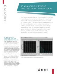
WHITE PAPER<br />
SIMULATING COMPLEX RF/MIXED-SIGNAL DESIGNS USING<br />
VIRTUOSO ULTRASIM FULL-CHIP SIMULATOR
TABLE OF CONTENTS<br />
1 Abstract . . . . . . . . . . . . . . . . . . . . . . . . . . . . . . . . . . . . . . . . . . . . . . . . . . . . . . . . . . . . . . . . . . . . . . . . . . . . 1<br />
2 Introduction . . . . . . . . . . . . . . . . . . . . . . . . . . . . . . . . . . . . . . . . . . . . . . . . . . . . . . . . . . . . . . . . . . . . . . . . 1<br />
3 Virtuoso UltraSim technology advantages . . . . . . . . . . . . . . . . . . . . . . . . . . . . . . . . . . . . . . . . . . . . . . . . 2<br />
4 Using Virtuoso UltraSim for RF/MS simulation . . . . . . . . . . . . . . . . . . . . . . . . . . . . . . . . . . . . . . . . . . . . 2<br />
5 Case studies . . . . . . . . . . . . . . . . . . . . . . . . . . . . . . . . . . . . . . . . . . . . . . . . . . . . . . . . . . . . . . . . . . . . . . . . 5<br />
6 Summary . . . . . . . . . . . . . . . . . . . . . . . . . . . . . . . . . . . . . . . . . . . . . . . . . . . . . . . . . . . . . . . . . . . . . . . . . . . 9<br />
TABLE OF FIGURES<br />
Figure 1 PLL simulation results . . . . . . . . . . . . . . . . . . . . . . . . . . . . . . . . . . . . . . . . . . . . . . . . . . . . . . . . . . .5<br />
Figure 2 RF PLL simulation results . . . . . . . . . . . . . . . . . . . . . . . . . . . . . . . . . . . . . . . . . . . . . . . . . . . . . . . . .6<br />
Figure 3 ADC simulation results . . . . . . . . . . . . . . . . . . . . . . . . . . . . . . . . . . . . . . . . . . . . . . . . . . . . . . . . . . .7<br />
Figure 4 Voltage generator simulation results . . . . . . . . . . . . . . . . . . . . . . . . . . . . . . . . . . . . . . . . . . . . . . .8<br />
Figure 5 Fast envelope following simulation results . . . . . . . . . . . . . . . . . . . . . . . . . . . . . . . . . . . . . . . . . .8
1 ABSTRACT<br />
Recently, the explosive growth in the wireless telecommunications market has created a strong demand<br />
for leading-edge EDA software to handle the complex design of RF/mixed-signal (MS) circuits. While<br />
traditional circuit simulators (such as Virtuoso ® Spectre ® Circuit Simulator) are suitable for accurate<br />
simulation of RF/MS building blocks, they are often too slow to simulate an entire circuit such as RF PLL or<br />
ADC/DAC, not to mention the RF/MS SoC, which often contains on-chip power regulators, RF/MS blocks,<br />
and large digital blocks.<br />
Virtuoso UltraSim Full-chip Simulator is a hierarchical FastSPICE simulator, well known for its capability in<br />
simulating multimillion transistor memory circuits. Virtuoso UltraSim's architecture and solver are also<br />
designed to target large MS circuits with working frequency from DC to multi-GHz. A key factor in<br />
simulating RF/MS circuits is the support of complex device models arising from advanced BiCMOS and<br />
deep submicron processes. Equally important is the support of HDL models (such as Verilog-A), which are<br />
often used to model components such as varactors and VCOs. Not only does Virtuoso UltraSim have the<br />
most extensive and updated model support, but it is also fully compatible with the Virtuoso Spectre<br />
simulator, as they use the same models. This automatically guarantees the consistency in the simulation<br />
results between the two simulators.<br />
The newly implemented AMR (analog multi-rate) simulation mode uses a novel numerical method to<br />
simulate circuit blocks with very different time steps, resulting in much faster and more robust simulation.<br />
Though most of the simulation options can be applied locally to allow tradeoffs between speed and<br />
accuracy for individual blocks, AMR mode provides users with a FastSPICE simulation mode that still works<br />
with simple options; other simulators often require the setting of many local options, which is not always<br />
easy to do. For RF circuits, accurate simulation is impossible without considering all the RC parasitic.<br />
Virtuoso UltraSim's frequency-based RC reduction and RC stitching technologies greatly speed up postlayout<br />
simulation of entire circuits with very little penalty on accuracy. This is especially important for<br />
RF/MS circuits where inaccurate simulation often generates meaningless results.<br />
2 INTRODUCTION<br />
There is no doubt that the hottest area of customer IC development is in the design of complex systemon-chip<br />
(SoC) products used in wireless applications such as cellular phones, WLAN, Bluetooth, and GPS. It<br />
is not uncommon to find RF/MS SoC designs consisting of more than one million transistors. Although<br />
98% of the million transistors are pure digital/memory blocks, the remaining 2% of circuitry — which can<br />
be any kind of RF or analog blocks such as ADC/DAC and PLL — accounts for 40% of the design effort. A<br />
conventional approach to simulate a mixed-signal circuit is to partition the design into digital and analog<br />
portions. Each analog block is individually simulated using traditional SPICE simulators such as the<br />
Virtuoso Spectre simulator or HSPICE, whereas logic simulators verify the digital blocks. Digital/analog cosimulators<br />
such as Virtuoso AMS <strong>Design</strong>er verify the top-level connectivity and full-chip functionality. To<br />
further speed up chip simulation, behavioral models may replace the analog blocks. Post-layout simulation<br />
can only be done on some critical analog blocks due to the limited capacity of the SPICE simulator.<br />
The rapid migration to nanometer technologies allows designers to push the working frequency into the<br />
multi-GHz range and to pack even more transistors into a chip, but it also creates new challenges for the<br />
simulation software. Very complex device models are used in RFCMOS, BiCMOS, SiGe, and SOI processes to<br />
model the RF operation. More design houses are using internal proprietary device models rather than<br />
standard models. Verilog-A models are used extensively to model components ranging from a simple<br />
resistor up to a complex VCO or a digital controller. The simulator also needs to support special RF<br />
elements such as lossy transmission lines, which may be modeled by S-parameters instead of lumped<br />
elements. Due to the finer geometry and lower signal swing, noise and crosstalk can no longer be<br />
neglected. IR drop on signal lines and power grids is becoming more critical as chips grow in size and<br />
power. The use of on-chip power regulators creates tight coupling between all the blocks through the<br />
power lines and even between the digital and analog blocks. Only full-chip transistor-level simulation can<br />
reveal these kinds of problems. The high-frequency performance is limited by interconnect delay and RC<br />
parasitic. Thus, chip-level post-layout simulation is the only way to guarantee meeting product<br />
specifications on first-pass silicon. The extracted netlist can easily have multi-million components. The<br />
simulator needs the capacity to handle the sheer size of a whole chip post-layout netlist, without<br />
1
compromising accuracy. More designers are relying on circuit simulators to check power consumption,<br />
standby current, floating nodes, dc leakage path, and excessive voltage stress on the devices. Only fullchip<br />
transistor-level simulation can provide the information needed to optimize timing, power, and<br />
reliability in nanometer designs, and the peace of mind before cutting the million-dollar mask set.<br />
3 VIRTUOSO ULTRASIM TECHNOLOGY ADVANTAGES<br />
Virtuoso Spectre Circuit Simulator and HSPICE are examples of the first generation of SPICE simulation<br />
products, which use compact analytical device models, a sparse matrix solver, and discretization<br />
techniques to solve simultaneous nonlinear equations. They provide very accurate results for simulation of<br />
analog circuits with up to 50K components (for acceptable simulation time). As circuit size and complexity<br />
outgrew the capability of the first-generation SPICE software, the so-called FastSPICE simulators were<br />
developed. The main ideas enabling this second-generation SPICE software to overcome the capacity and<br />
speed limits of the older, more conventional products are: 1) partitioning; 2) multi-rate/event-driven<br />
simulation; and 3) using table device models.<br />
Partitioning is the process of dividing a design into different parts. Each partition is represented as a<br />
matrix that can be solved separately during simulation. Instead of solving one huge matrix, secondgeneration<br />
simulation software solves multiple smaller matrices. This can greatly reduce CPU time and<br />
memory consumption. Another advantage of the partitioning approach is that each partition can be<br />
simulated with different time steps. The time step for each partition is adjusted according to the<br />
maximum signal frequency within each partition. This is known as multi-rate simulation. In fact, the<br />
partitions are only evaluated when there are activities (events) at their inputs; otherwise they can be<br />
skipped. This is the basis of event-driven simulation. Multi-rate and event-driven simulations result in a<br />
tremendous speed improvement over conventional SPICE simulators. This is especially beneficial for<br />
mixed-signal designs, which generally consist of circuit blocks with very different working frequencies.<br />
SPICE simulators use complex analytical device models for MOSFETs and BJTs. These models are basically a<br />
set of nonlinear equations that need to be solved at each time step. Since the evaluation of these<br />
equations consumes a significant CPU time, second-generation simulation software uses simplified<br />
equations and table models to speed up the computation of the I-V and Q-V characteristics. In general,<br />
second-generation simulation software lets users select different levels of model abstraction according to<br />
the required accuracy for each circuit block. For instance, the digital blocks use simplified digital table<br />
models, whereas the analog blocks use more accurate analog table models.<br />
The first two generations of simulation products are based on flat netlists. Virtuoso UltraSim is the thirdgeneration<br />
SPICE simulator, which adds isomorphic hierarchical simulation techniques with adaptive<br />
partitioning. The hierarchical simulation approach is based on the fact that most circuits have repetitive<br />
structures. Digital designs use standard gates; memory circuits consist of millions of identical memory cells;<br />
and mixed-signal designs have repetitive circuit blocks. For subcircuits that have the same topology and<br />
stimuli, only a representative master needs to be simulated. This approach enables third-generation<br />
products to simulate virtually any size of hierarchical circuit, while still providing SPICE-like accuracy. As<br />
the stimuli change dynamically during simulation, partitions (and the representation of identical<br />
partitions) can be split or re-grouped.<br />
4 USING VIRTUOSO ULTRASIM FOR RF/MS SIMULATION<br />
Virtuoso UltraSim is a fast, high-capacity simulator, but it is also a highly accurate SPICE simulator for<br />
analog/RF circuits with working frequency from DC up to multi-GHz. Unlike other FastSPICE simulators,<br />
which are basically digital solvers with an add-on analog simulation mode, Virtuoso UltraSim employs the<br />
same SPICE simulation engine for the entire circuit and for all simulation modes. This guarantees “fulltime”<br />
SPICE-like accuracy for all kinds of designs. For those circuits that do not require the highest<br />
accuracy, users can trade off accuracy for speed. In general, the accuracy of SPICE simulation is determined<br />
by the accuracy of the models and the simulation engine, which is, in turn, determined by tolerance<br />
criteria used by the solver. Virtuoso UltraSim allows users to adjust each of them independently. The<br />
simulation mode (sim_mode) specifies partitioning and the selection of device models, while the speed<br />
option (speed) determines the simulation engine tolerance.<br />
2
SPICE (S) mode is the most conservative (accurate) mode and is equivalent to conventional SPICE software.<br />
The entire circuit is simulated as a single partition using full analytical model equations. Analog (A) mode<br />
uses no partitioning as S mode, but achieves a speed improvement of three to five times by using analog<br />
table models. Mixed-signal (MS) mode shares the same table models with analog mode, but achieves<br />
additional speed by partitioning the design. Analog multi-rate (AMR) mode is designed to achieve MS<br />
mode speed with A mode accuracy and robustness. It uses the same analog table models as A mode and<br />
employs a similar partitioning approach as MS mode, but the solver uses a novel technique to accurately<br />
and efficiently handle the interaction between the partitions. Using AMR mode is as easy as using A mode<br />
because local options are often not required. Digital accurate (DA) mode and digital fast (DF) mode both<br />
use partitioning and digital table models. While the DF mode uses linear grounded device capacitance,<br />
the DA mode takes into account the nonlinear capacitive coupling within the models. DF mode is<br />
designed for the functional verification of digital and memory circuits. DA mode is intended for the<br />
timing verification of the same applications. Once users have chosen the appropriate simulation mode for<br />
their application, they can adjust the “speed dial” to control the accuracy of the simulation engine<br />
according to the circuit requirement. The speed option can be set with a value from one to eight to<br />
define the relative tolerance used by the solver. Both simulation modes and speed options (as well as<br />
many other options) can be applied globally to the entire circuit or locally to each subcircuit (master), and<br />
to each instance of the subcircuits or each device model.<br />
Correct partitioning and selection of device models are the two key factors to achieve efficient and<br />
accurate simulation of mixed-signal circuits. MS mode is the default simulation mode and is suitable for<br />
most mixed-signal circuits. The default speed option (speed=5) is a good starting point for most circuits<br />
and often can produce accurate enough results. These two options are normally set as the global options.<br />
Next, local sim_mode and speed options can be set for individual blocks. For instance, sim_mode=da or df<br />
and higher speed option (6-8) can be set for the digital and embedded memory blocks. Analog and RF<br />
blocks must be simulated in A or S mode. In MS mode, Virtuoso UltraSim will automatically partition the<br />
entire design according to the circuit topology and channel connectivity (devices that are channelconnected<br />
are placed in one partition.)<br />
While this algorithm works well for most circuits, in some situations there may be vigorous interactions<br />
between different partitions, which can actually slow down simulation and/or degrade accuracy. The user<br />
can correct this situation by setting the analog option. Set analog=2 or 3 will cause Virtuoso UltraSim to<br />
increase the partition size. For example, with the default option of analog=1, a partition is large enough<br />
to hold a simple ring oscillator. Setting analog=2 will increase the partition size to hold a complex<br />
differential type ring oscillator. With analog=3 a partition can grow large enough to hold a small PLL. A<br />
more direct way to control partitioning is to use the local sim_mode option. Assigning sim_mode=a or s to<br />
a subcircuit ensures that the subcircuit will be simulated as a single partition (in addition to using analog<br />
models). Sensitive analog blocks, which have feedback action or tight coupling between elements (such as<br />
RF VCO, bandgap, op amp circuits, switched capacitor circuits, charge pumps, and virtually all RF blocks),<br />
have to be simulated in A or S mode to ensure accuracy. S mode is mainly for comparison to conventional<br />
SPICE products and is not needed for most circuits. Virtuoso UltraSim analog table models are accurate<br />
enough for most applications. However, the following categories of circuits may require full analytical<br />
models to achieve the required accuracy (very often a lower speed option is also required):<br />
• High-precision analog circuits (bandgap circuits, high resolution ADC/DAC, op amp circuits)<br />
• RF VCOs using LC tank circuits<br />
• Some RF circuits<br />
• Circuits consisting mainly of BJTs<br />
• Circuits with MOSFETs operating in the sub-threshold region<br />
PLL is probably the most important mixed-signal circuit that also consumes most of the simulator resource.<br />
All PLLs share the same topology, but their complexity and working frequency can vary considerably. For<br />
PLLs with fewer than 5K components and VCO frequency below 100MHz, it may be simpler to simulate<br />
the entire loop in A mode to obtain robust results. Usually no local option is required. Typical simulation<br />
time from start up to lock acquisition is about a half day to one full day. For very complex PLLs, RF PLLs, or<br />
3
PLLs with post-layout netlists, MS mode should be used to speed up simulation. If the PLL fails to operate<br />
properly, users can try the global option analog=2 or 3. A common problem is that the VCO fails to start,<br />
in which case the following local options for the VCO may need to be set:<br />
• sim_mode=a<br />
• speed=3 or 4<br />
• method=trap or gear2<br />
Some VCO circuits with lower loop gain might need a kick start. For RF VCOs with inductors, a common<br />
trick is to connect a transient current source (1mA, 0.1ns duration) in parallel with each inductor. For ring<br />
oscillator type VCOs, it can be done by forcing one or two of the internal nodes to high/low at the onset<br />
of simulation (by using an initial condition statement).<br />
For PLLs with postlayout netlists, the user may need to turn on RC reduction using the postl option.<br />
Virtuoso UltraSim supports all major post-layout netlist formats such as SPEF, DSPF, and DPF. Its RC<br />
backannotation approach is optimized to stitch the RC parasitic of the flat DSPF/SPEF data into the<br />
hierarchical schematic netlist. Virtuoso UltraSim will also compact the RC networks while preserving their<br />
electrical behavior. The user can specify five levels of RC reduction:<br />
• No RC reduction (postl=0)<br />
• Conservative RC reduction (postl=1)<br />
• Moderate RC reduction (postl=2)<br />
• Liberal RC reduction (postl=3)<br />
• Keep parasitic Cs only, short all parasitic Rs (postl=4)<br />
Virtuoso UltraSim's superior RC reduction techniques make it possible to reduce the number of RCs by up<br />
to 90% while still producing accurate results. Since accuracy is of paramount importance for RF/MS<br />
simulation, the user should choose post=1 or 2 for post-layout simulation. It should be noted that the<br />
current implementation of RC reduction algorithm does not support reduction of extracted inductance.<br />
For those extracted netlists containing many parasitic inductances, a solution is to use the lshort option to<br />
eliminate most of the small inductance and only keep the larger ones. Then the postl option can be<br />
applied to enable RC reduction.<br />
Many mixed-signal and memory circuits consist of on-chip voltage regulators and charge pumps.<br />
Simulating these circuits in MS mode often produces unsatisfactory results due to the tight interaction<br />
between partitions through the internal power lines. Simulation in A mode will be too slow due to the<br />
size of the circuit. Virtuoso UltraSim AMR mode is designed for these applications. AMR mode uses a<br />
novel solver technique to handle the interaction between partitions and should be used for the following<br />
categories of circuits:<br />
• Circuits using internal voltage generators or charge pumps<br />
• Power up simulation of analog and mixed-signal circuits<br />
• Smaller- and medium-sized designs with inductors or resistors in the power nets<br />
• Sensitive or high-precision designs with more than 30K devices<br />
• Circuits with excessive interaction between partitions, but are too large to be handled by A mode<br />
Virtuoso UltraSim is the only FastSPICE simulator that supports fast envelope following transient<br />
simulation. Many RF circuits process signals generated with high-frequency carriers modulated by lowfrequency<br />
baseband signals using various schemes such as amplitude, phase, and frequency modulation.<br />
Conventional transient analysis is inefficient for these circuits due to the widely spread signal frequencies,<br />
which require the time duration to follow the slow modulating signals, but the time steps depend on the<br />
fast carrier signals, resulting in a prohibitively large number of time steps. Traditional envelope-following<br />
methods suffer from the bottleneck of limited capacity. Virtuoso UltraSim employs a novel approach for<br />
large-capacity, fast envelope following analysis based on the pseudo-spectral method, which approximates<br />
signals with high-order polynomials or Harmonic basis functions to achieve spectral accuracy like<br />
Harmonic Balance.<br />
4
In this technique, the signal is expressed as the sum of an envelope part and a high-frequency part.<br />
Taking advantage of the slow change of the envelope, only one time point in a period of the fast carrier<br />
signal has to be solved. Additional techniques are applied to ensure convergence and accuracy. The new<br />
approach shows speed improvement up to 30 times over conventional transient analysis and is still<br />
effective for large-scale RF circuits.<br />
Finally, Virtuoso UltraSim supports virtually all the elements and device models accepted by Virtuoso<br />
Spectre Circuit Simulator and HSPICE. Virtuoso UltraSim also supports Verilog-A as well as Spectre HDL<br />
languages; both are widely used in device models and circuit behavioral models for mixed-signal<br />
simulation. Virtuoso UltraSim and Virtuoso Spectre simulators share the same source codes for the<br />
Verilog-A engine and device models (through CMI), which guarantees full compatibility between the two<br />
simulators. Users can even link their own compiled device models into Virtuoso UltraSim in the same way<br />
as they do with the Virtuoso Spectre simulator. This is gaining importance as more design houses are<br />
relying on their own internal proprietary models. With this feature, they do not need to rely on the<br />
simulator vendor to implement the new models. For mixed-signal simulation, Virtuoso UltraSim supports<br />
both Virtuoso Spectre and HSPICE netlist formats, as well as structural Verilog ® netlists.<br />
5 CASE STUDIES<br />
PLL<br />
The first circuit is a computer data bus interface controller. It consists of a receive path PLL (RXPLL), a<br />
transmit path PLL (TXPLL), and large digital blocks (XDIGITAL) for data processing, as well as built-in-selftest<br />
(BIST). The pre-layout HSPICE format netlist has 70K MOSFETs and 35K diodes. For both PLLs, the<br />
input reference clock is 50MHz and the VCO is running at 1.25GHz. The following options are used for the<br />
Virtuoso UltraSim simulation:<br />
.usim_opt sim_mode=ms speed=5<br />
.usim_opt sim_mode=a #TXPLL #RXPLL<br />
.usim_opt sim_mode=df speed=6 dcut=1 XDIGITAL<br />
The entire circuit is simulated in MS mode (sim_mode=ms) with default accuracy (speed=5). Setting<br />
sim_mode=a for both PLLs forces Virtuoso UltraSim to place each PLL in a single partition. This<br />
guarantees robust and accurate results without requiring any local options. This is an acceptable strategy<br />
since each PLL contains fewer than 3K elements. The large digital block, XDIGIAL, is simulated in DF mode<br />
with a slightly looser accuracy (speed=6). In addition, all the protection diodes in the logic gates are<br />
removed from the netlist to speed up simulation (dcut=1). Running Virtuoso UltraSim on a 3GHz Linux<br />
platform, the simulation time for a 25us transient (which covers start up to lock acquisition) is 44 hours.<br />
Figure 1 shows the VCO clock (CKVCO), the reference (CKREF), and feedback (CKFB) signals at the phase<br />
detector input after lock acquisition.<br />
Figure 1: PLL simulation results<br />
5
RF PLL<br />
The second circuit is an RF PLL for wireless applications. The Virtuoso Spectre pre-layout netlist consists of<br />
21K MOSFETs, 400 BJTs, 50K diodes, and about 1K R/Cs. The reference clock is 26MHz and the LC type VCO<br />
is running at 3.5GHz. The following options are used for the Virtuoso UltraSim simulation:<br />
.usim_opt sim_mode=ms speed=5 analog=3<br />
.usim_opt speed=4 method=gear2 IPLL.VCO<br />
.usim_opt sim_mode=df IPLL.LOGIC<br />
Since this PLL contains a large number of elements, the entire circuit has to be simulated in MS mode for<br />
efficiency. The option analog=3 will cause Virtuoso UltraSim to use very conservative partitioning to avoid<br />
breaking any feedback loop. Local options of speed=4 and method=gear2 are assigned to the VCO. Most<br />
RF VCOs require the setting of trap or gear method and tighter solver tolerance for starting and<br />
maintaining oscillation. The digital block is simulated with digital table models as set by the option<br />
sim_mode=df. The simulation time for a 25us transient (from power up to lock acquisition) is 21 hours.<br />
Figure 2 shows the VCO output signal (CKVCO), the reference (CKREF), and feedback (CKFB) signals at the<br />
phase detector input after lock acquisition.<br />
Figure 2: RF PLL simulation results<br />
ADC<br />
The third circuit is a high-speed 6-bit flash ADC with a data conversion rate of 2G-samples/sec. For such a<br />
high working frequency, full-chip post-layout simulation is required to verify the operation of the design.<br />
The Virtuoso Spectre netlist consists of 15K MOSFETs, 3K diodes, 80K extracted inductors, 150K extracted<br />
resistors, and 640K extracted capacitors. The entire netlist has about 0.9M elements. The following option<br />
is used for the Virtuoso UltraSim simulation:<br />
.usim_opt sim_mode=ms speed=5 lshort=0.1n postl=1<br />
6
The circuit is simulated in MS mode with default accuracy. The option postl=1 enables first-level RC<br />
reduction. Since the current RC reduction algorithm will not compact networks containing inductors, the<br />
option lshort=0.1n is used to short out most of the inductors except the 700 largest ones with values<br />
larger than 0.1nH. Because of the RC reduction, the total number of elements is reduced to 270K. The<br />
simulation time for a 50ns transient is 10.4 hours. Figure 3 shows the analog input (Vin) and digital output<br />
(Dout*) signals of the ADC. On the simulated waveforms, the effects of coupling from the high-frequency<br />
clock on the digital outputs are evident.<br />
Figure 3: ADC simulation results<br />
VOLTAGE GENERATORS<br />
The fourth circuit is the internal power supply system of a DRAM chip. The operation of DRAM cells<br />
requires multiple supply voltages, which are different from the external supply voltage. In addition, a<br />
negative substrate bias (vbb) is employed to reduce junction capacitance. These voltages are generated by<br />
the on-chip charge pumps and voltage regulators. The pre-layout netlist of this example consists of 3K<br />
MOSFETs and 3K R/Cs. On-chip voltage generators are good candidates for the AMR mode, which is<br />
enabled with the following option:<br />
.usim_opt sim_mode=amr<br />
The following are simulation times for the AMR, A, and MS modes (speed=5 for all cases):<br />
AMR mode: 25 min<br />
A mode: 41 min<br />
MS mode: 6 hr 20 min<br />
7
The inefficiency of MS mode is due to the feedback actions between different partitions. Specialized<br />
partitioning options will soon be available in AMR mode to increase speed. Figure 4 shows the simulated<br />
waveforms of the regulator outputs (vddh, vddl, vbb) and one of the charge pump clock signals (pumpclk).<br />
Figure 4: Voltage generator simulation results<br />
FAST ENVELOPE FOLLOWING SIMULATION<br />
In this example, Virtuoso UltraSim's fast envelope following analysis will be demonstrated. This is a largescale<br />
RF circuit consisting of 13K MOSFETs, 1K diodes, 100 BJTs, 100 inductors, 700 mutual inductors, 1.5K<br />
control CMI elements, and 3.5K R/Cs. The carrier frequency is 1.8GHz. Using Virtuoso UltraSim's A mode, it<br />
will take 59 minutes to finish simulation of a 1us transient. The simulation can be sped up by enabling the<br />
following fast envelope following analysis options:<br />
.usim_opt env_clockf=1.8G env_tstart=5ns env_maxnstep=40<br />
.usim_opt sim_mode=a method=gear2<br />
Env_clockf sets the carrier clock frequency while env_maxnstep sets the maximum number of carrier cycles<br />
subjected to “envelope solve” (solving only one point per clock period). Using the new options, the same<br />
simulation required only 11.5 minutes, achieving a six-fold speed up. Figure 5 compares the output<br />
waveforms generated from the conventional transient simulation and the fast envelope following analysis.<br />
Figure 5: Fast envelope following simulation results<br />
8
6 SUMMARY<br />
Virtuoso UltraSim provides a powerful solution for accurate and efficient simulation of RF and mixedsignal<br />
(MS) circuits. It enables circuit designers to consider nanometer effects that can only be revealed by<br />
full-chip transistor-level simulation. The core of Virtuoso UltraSim is a true SPICE simulator, which provides<br />
the foundation for accurate simulation of RF and analog circuits. Based on technologies such as<br />
partitioning, multi-rate/event-driven methods, table models, and the hierarchical structure of most<br />
circuits, Virtuoso UltraSim can simulate full-chip RF/MS circuits not possible with other conventional<br />
simulators. The characteristics of RF circuits are dominated by the layout parasitic. Virtuoso UltraSim<br />
parasitic backannotation and superior RC reduction technology allows post-layout simulation to be<br />
performed on a chip level rather than on a block level. Virtuoso UltraSim is also easy to use.<br />
Simulation mode and speed are the only two major options that can be applied globally or to individual<br />
circuit blocks. The default MS mode is good for most mixed-signal designs, but some critical RF/analog<br />
circuits have to be simulated in A mode to produce accurate results. Currently the new AMR mode is good<br />
for power-up simulation and for designs with on-chip power generators or charge pumps. In the near<br />
future, there will be a generic simulation mode that always works as robust as A and S modes, but with<br />
FastSPICE speed.<br />
Virtuoso UltraSim is the only FastSPICE simulator supporting fast envelope following transient simulation.<br />
Simulation of RF circuits, which have a high-frequency carrier modulated by a low-frequency signal, can<br />
be sped up by as much as 30 times. Virtuoso UltraSim has the best model support among all the<br />
competitors in the industry. In addition, it also supports custom compiled models. With its superior<br />
simulation capabilities, Virtuoso UltraSim is the simulator of choice for RF/MS SoC simulation.<br />
9
<strong>Cadence</strong> <strong>Design</strong> <strong>Systems</strong>, Inc.<br />
Corporate Headquarters<br />
2655 Seely Avenue<br />
San Jose, CA 95134<br />
800.746.6223<br />
408.943.1234<br />
www.cadence.com<br />
© 2005 <strong>Cadence</strong> <strong>Design</strong> <strong>Systems</strong>, Inc. All rights reserved. <strong>Cadence</strong>, the <strong>Cadence</strong> logo, Spectre,<br />
Verilog, and Virtuoso are registered trademarks of <strong>Cadence</strong> <strong>Design</strong> <strong>Systems</strong>, Inc. All others are<br />
properties of their respective holders.<br />
<strong>6114</strong> 03/05