Cadence Analog/Mixed-Signal Design Methodology Overview
Cadence Analog/Mixed-Signal Design Methodology Overview
Cadence Analog/Mixed-Signal Design Methodology Overview

You also want an ePaper? Increase the reach of your titles
YUMPU automatically turns print PDFs into web optimized ePapers that Google loves.
OVERVIEW<br />
AMS DESIGN METHODOLOGY<br />
The <strong>Cadence</strong> AMS <strong>Design</strong> <strong>Methodology</strong> delivers an extensive<br />
design and data flow guide, from design specification through<br />
design manufacturing, across the different functions of a design<br />
team. It is based on executable design tasks and recommended<br />
use models for fast, silicon-accurate mixed-signal design that<br />
ensures first-pass silicon success. The AMS <strong>Design</strong> <strong>Methodology</strong><br />
addresses the analog-driven mixed-signal design process front to<br />
back by executing well-defined flows that demonstrate a meetin-the-middle<br />
approach, in which all design flows are running in<br />
parallel to minimize design iterations, maximize project resource<br />
utilization, and enhance design quality.<br />
The AMS <strong>Design</strong> <strong>Methodology</strong> addresses the entire design<br />
process and comprises five major flows:<br />
1. <strong>Design</strong> environment and infrastructure<br />
2. Top-down functional verification<br />
3. AMS IP block creation and reuse<br />
4. AMS IP export and integration<br />
5. Top-down physical design<br />
CADENCE ANALOG/<br />
MIXED-SIGNAL DESIGN<br />
METHODOLOGY<br />
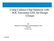
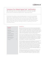
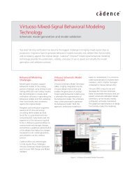
The <strong>Cadence</strong> ® <strong>Analog</strong>/<strong>Mixed</strong>-<strong>Signal</strong> (AMS) <strong>Design</strong> <strong>Methodology</strong> employs<br />
advanced <strong>Cadence</strong> Virtuoso ® custom design technologies and leverages<br />
silicon-accurate design flows to help design teams create differentiated silicon<br />
faster and with less risk. It delivers verified and packaged methodologies<br />
demonstrated on a real-world mixed-signal design. The <strong>Cadence</strong> AMS <strong>Design</strong><br />
<strong>Methodology</strong> combines the best of top-down (behavioral and mixed-level<br />
approaches) with bottom-up (transistor-level design and abstraction) design<br />
techniques to achieve predictable, high-quality results for complex mixedsignal<br />
designs.<br />
<strong>Design</strong> environment<br />
and infrastructure<br />
Top-down functional verification<br />
AMS IP block creation and reuse<br />
Top-down physical design<br />
Figure 1: The <strong>Cadence</strong> AMS <strong>Design</strong> <strong>Methodology</strong> consists of five main flows<br />
AMS IP export<br />
and integration
<strong>Design</strong> Data<br />
Input<br />
1A<br />
Target<br />
CDK<br />
(90nm)<br />
1B<br />
<strong>Design</strong><br />
Specs<br />
1C<br />
System-Level<br />
Models<br />
and Sims<br />
1D<br />
Third-Party<br />
IP<br />
1E<br />
Legacy<br />
IP<br />
Top-Down Functional <strong>Design</strong><br />
2<br />
AMS Block<br />
Validation Strategy<br />
3<br />
AMS Block <strong>Design</strong><br />
Partitioning<br />
4<br />
Sub-Blocks<br />
Specifications<br />
5A<br />
<strong>Analog</strong> Block<br />
Circuit <strong>Design</strong><br />
5B<br />
<strong>Analog</strong> Block<br />
Behavioral <strong>Design</strong><br />
5C<br />
<strong>Analog</strong> Block<br />
Circuit Migration<br />
5D<br />
Digital Hierarchical<br />
RTL <strong>Design</strong><br />
5E<br />
Block IP<br />
Top-Down Physical <strong>Design</strong><br />
6<br />
AMS Block<br />
Functional<br />
Concept<br />
Validation<br />
Bottom-up Functional and Physical <strong>Design</strong><br />
8A<br />
<strong>Analog</strong> Block<br />
Circuit <strong>Design</strong> and<br />
Optimization<br />
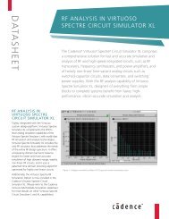
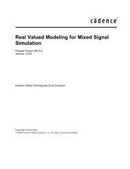
The five flows are further divided into modules of logically related<br />
design tasks, which are illustrated and documented with in-context<br />
scenarios. The different scenarios are demonstrated on a siliconimplemented<br />
and verified real-life design, namely an Ethernet<br />
physical layer macro (PHY) and a sigma-delta fractional-N PLL<br />
frequency synthesizer macro for WLAN applications. The Ethernet<br />
PHY contains 20k analog devices and 30k digital gates including<br />
typical analog, digital, and mixed-signal blocks such as flash ADC,<br />
VGA, equalizer, and clock recovery circuit. The fractional-N PLL is a<br />
2.4GHz synthesizer that contains 20k devices and includes a 5GHz<br />
LC VCO, a high-speed divider, on-chip regulators, and a calibration<br />
mechanism for loop filtering and VCO.<br />
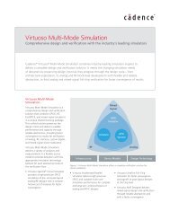
Both Ethernet PHY and frac-N PLL are implemented on a 90nm<br />
generic process design kit (GPDK), which has virtually all the<br />
aspects of an actual design kit. The design blocks have all the<br />
necessary views for complete design, including symbols,<br />
schematics, constraints, behavioral models, abstracts, layout, and<br />
extracted views, as well as configurations, testbenches, and<br />
simulation states. A design team can use the reference design as<br />
a basis to enter a new design domain, understand a wide range<br />
of new Virtuoso technologies, acquire new methodologies, and<br />
map selected elements onto their own design environment.<br />
7<br />
AMS Block Early<br />
Floorplanning<br />
8B<br />
Digital <strong>Design</strong><br />
Synthesis<br />
8C<br />
Block IP<br />
Qualification<br />
9<br />
AMS Block<br />
Functional<br />
Performance<br />
Validation<br />
11<br />
AMS Block<br />
Refinement<br />
Floorplanning<br />
14<br />
Block Physical<br />
Integration<br />
Preparation<br />
www.cadence.com CADENCE ANALOG/MIXED-SIGNAL DESIGN METHODOLOGY<br />
10A<br />
Block Physical<br />
Estimation<br />
10B<br />
Block IP Physical<br />
Import<br />
12A<br />
<strong>Analog</strong> Physical<br />
<strong>Design</strong><br />
12B<br />
Digital Block<br />
Physical <strong>Design</strong><br />
12C<br />
Block IP Layout<br />
Integration<br />
12D<br />
<strong>Analog</strong> Block<br />
Layout Migration<br />
13<br />
AMS Block<br />
Functional<br />
Post-Layout<br />
Validation<br />
16<br />
AMS Block<br />
Functional<br />
Signoff<br />
Validation<br />
15<br />
AMS Block<br />
Assembly<br />
Figure 2: The combination of top-down (behavioral/mixed-level) and bottom-up (transistor-level design/abstraction) techniques ensures high-quality results<br />
ETHERNET PHY Transceiver Macro<br />
Rx<br />
Digital<br />
10BASE-T<br />
Receiver<br />
10BASE-TX<br />
Receiver<br />
60k Gate<br />
<strong>Analog</strong> 30k Device<br />
PFD &<br />
CP<br />
Clk<br />
Tx<br />
dvdd/dgnd<br />
Modulator<br />
Control<br />
Loop<br />
Filter<br />
1.2V Regulator (HF)<br />
1.2V Regulator (LF)<br />
Polarity Correction<br />
Squelch Link Detect<br />
VGA Control<br />
Digital Equalizer/Slicer<br />
Timing/BLW Control<br />
10BASE-T PLL<br />
100BASE-TX PLL<br />
10BASE-T<br />
Driver<br />
100BASE-TX<br />
Driver<br />
Autonegotiation<br />
MLT-3<br />
Dedoder<br />
Scrambler<br />
dvdd/dgnd<br />
∆∑<br />
Modulator<br />
Multi-<br />
Modulus<br />
Divider<br />
Clock Recovery<br />
Manchester Decoder<br />
MLT-3<br />
Decoder<br />
Descrambler<br />
Manchester Encoder<br />
Digital Waveshaping<br />
1.2V (LF)<br />
1.2V (LF) 1.2V (HF) 1.2V (HF) 1.2V (HF)<br />
LPF VCO<br />
Collision<br />
Carrier Sense<br />
RC VCO<br />
Calibration Calibration<br />
Control Control<br />
dvdd/dgnd dvdd/dgnd<br />
4B/5B<br />
Decoder<br />
4B/5B<br />
Encoder<br />
ATB<br />
<strong>Design</strong> Data<br />
Output<br />
17<br />
AMS Block<br />
Preparation<br />
for SoC<br />
Integration<br />
1.2V (HF)<br />
I & Q<br />
Divide<br />
by 2<br />
Figure 3: The <strong>Cadence</strong> AMS <strong>Design</strong> <strong>Methodology</strong> is demonstrated<br />
on a real-world mixed-signal design<br />
MII<br />
2
FEATURES<br />
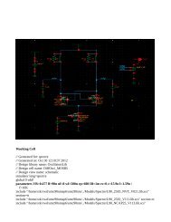
DESIGN ENVIRONMENT AND INFRASTRUCTURE<br />
Any design process takes place in a certain environment including<br />
different projects, CAD tools, process design kits (PDKs), and users<br />
on different hardware platforms and operating systems. It is very<br />
important to create a consistent design environment to ensure the<br />
quality of the design and the credibility of the results.<br />
This part of the <strong>Cadence</strong> AMS <strong>Design</strong> <strong>Methodology</strong> gives the<br />
foundation to set up a design environment using tested and<br />
proved methods and technologies, including incremental tool<br />
access, project directory structure, how to set up and control<br />
PDKs, and how to automate project and flow setup using the<br />
<strong>Design</strong> Environment and Configuration Manager.<br />
The data exchange between the design house and the foundry is<br />
explained, detailing required datasets from the foundry and how<br />
to qualify them against the defined AMS flows. Special attention<br />
is given to the PDK—how to automatically check its content<br />
using the Data Surveyor and how to use the Incremental<br />
Technology Database (ITDB) to customize and enhance the PDK<br />
<strong>Design</strong><br />
libraries<br />
/projects/<br />
ProjectA/ ProjectB/ ProjectC/<br />
deslibs/<br />
Working<br />
libraries<br />
doc/<br />
Project<br />
Documents<br />
user1/ user2/<br />
.cdsinit .cds.lib<br />
assura_tech.lib<br />
.csdenv<br />
display.drf<br />
hdl.var<br />
TOP-DOWN FUNCTIONAL VERIFICATION<br />
A comprehensive functional verification flow is presented,<br />
spanning all levels of abstraction and all design stages, from<br />
planning to post-layout device-level signoff verification. First, an<br />
introduction to the concept of design partitioning and simulation<br />
planning is given. Next, behavioral modeling guidelines and<br />
testbench strategies are presented.<br />
A consistent testbench structure is used over all later stages of<br />
verification, starting with concept validation using behavioral<br />
model representation in AMS simulation, and system validation<br />
using Simulink/AMS co-simulation. Next is performance<br />
validation using mixed-level-transistor plus behavioral-level<br />
simulation on Virtuoso AMS <strong>Design</strong>er Simulator with SDF<br />
backannotated to the digital part.<br />
Finally, a post-layout and signoff verification is prepared to include<br />
both analog extracted parasitics and SDF backannotation for the<br />
most accurate timing estimation using Virtuoso AMS-Ultra<br />
Simulator. An IDDQ analysis is performed using full extracted<br />
transistor-level DC simulation with the Virtuoso UltraSim Full-Chip<br />
Simulator along with top-level EM IR drop analysis.<br />
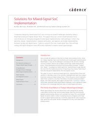
Figure 4: AMS design environment and infrastructure Figure 5: AMS top-down functional verification<br />
www.cadence.com CADENCE ANALOG/MIXED-SIGNAL DESIGN METHODOLOGY<br />
3
AMS IP BLOCK CREATION AND REUSE<br />
A thorough approach to creation of both analog and digital blocks<br />
is presented using productivity-oriented Virtuoso technology. The<br />
constraints concept and management is used to amend the<br />
schematic with the required information to automatically create its<br />
layout. Furthermore, constraints can be inferred from pre-defined<br />
circuit structures using the Circuit Prospector Assistant.<br />
New layout techniques like design-rule–driven (DRD), module<br />
generator (Modgen), and constraint-driven editing are shown in<br />
action through a dedicated assisted layout module. A new approach<br />
to simulation is shown through the specification-oriented simulation<br />
platform (Virtuoso <strong>Analog</strong> <strong>Design</strong> Environment) with its numerous<br />
productivity enhancement features including simulation history,<br />
check points manager, parameterization flow, design specifications,<br />
and parasitic estimation flow. The high-capacity Virtuoso <strong>Analog</strong><br />
<strong>Design</strong> Environment optimization engine is used for local and global<br />
optimization on the block level, over corners, and as a yield<br />
optimizer with Monte Carlo and sensitivity analyses.<br />
Figure 6: AMS IP block creation and reuse<br />
Later, Virtuoso Layout Optimizer is used to boost the yield on<br />
the back end. A tutorial introduction to analog-driven digital<br />
implementation using the Virtuoso Digital Implementation Option<br />
shows a typical digital layout flow including planning, prototyping,<br />
placement, routing, timing optimization, clock tree synthesis, SDF<br />
generation, parasitic extraction, and parasitic closure.<br />
AMS IP EXPORT AND INTEGRATION<br />
The IP flow is a comprehensive guide for analog and digital IP<br />
handling, from top-level integration to extensive characterization<br />
and packaging. On the exporting side, a complete step-by-step<br />
scenario of characterizing and modeling an analog IP in Verilog ® -<br />
AMS is presented, taking an N-bit flash ADC as an example.<br />
Automated testbench extraction is discussed; generic behavioral<br />
model planning, coding, and debugging is illustrated. The model<br />
includes advanced features like noise, aperture time, INL, and DNL<br />
parameters. The layout abstract is generated using the Virtuoso<br />
Abstract Generator. The timing information (.lib) file for top-level<br />
digital integration is generated using Virtuoso Spectre ® MDL<br />
language and verified by importing to the <strong>Cadence</strong> Encounter ®<br />
platform. Finally, packaging of all generated views for publishing is<br />
discussed and implemented using Vulcan technology.<br />
Target PDK<br />
Target DFH library<br />
where generated<br />
DFH will be located<br />
Repository directory<br />
where non-DFH<br />
outputs will be stored<br />
Processing scratch run<br />
directory for various<br />
log files and<br />
temporary data<br />
Inherited connections<br />
definition for<br />
global nodes<br />
Definition of power<br />
and ground nodes<br />
used at several stages<br />
of view creation (RCX,<br />
CeltiC, VoltageStorm)<br />
Figure 7: AMS IP export and integration<br />
List of cell found in<br />
various inputs data and<br />
the target repository<br />
library if it already exists<br />
Each entry represents a<br />
cell and columns<br />
represents views that<br />
need to be created and<br />
to be re-used<br />
Selection of views<br />
to be created<br />
www.cadence.com CADENCE ANALOG/MIXED-SIGNAL DESIGN METHODOLOGY<br />
4
On the importing and integration side, feasibility of IP integration<br />
employing multi-technology simulation (MTS) is exemplified,<br />
followed by actual import using Vulcan technology. Legacy cdb<br />
file import into the Virtuoso OpenAccess (OA) database is shown.<br />
Importing of digital IP in an analog context is also presented.<br />
TOP-DOWN PHYSICAL DESIGN<br />
The physical design flow introduces a true top-down approach to<br />
chip layout using state-of-the-art Virtuoso technologies. Special<br />
emphasis is given to early floorplanning to get information about<br />
the critical parasitics to feed back to the verification flow. This is<br />
possible through a Virtuoso Floorplanner, a Physical Hierarchy<br />
Configurator, and an Abstract Generator, along with several<br />
floorplanning techniques like connectivity analysis, area<br />
estimation, pushdown block shaping, and pin optimization. The<br />
flow is illustrated on the PLL.<br />
The analog-oriented physical assembly and routing is described<br />
using both Virtuosos Chip Assembly Router and Virtuoso Space-<br />
Based Router, both accepting design constraints. The flow is<br />
demonstrated by top-level routing of the Ethernet PHY and the<br />
PLL macro using advanced analog routing techniques like critical<br />
signal, differential signal, shielded signal, bundle, and supply<br />
routing. After routing, chip finishing is applied, including metal<br />
density and antenna checks, metal filling, and guard rings.<br />
Figure 8: AMS top-down physical design<br />
The assembled layout is then verified using <strong>Cadence</strong> Assura ®<br />
verification technology with dedicated scenarios for <strong>Design</strong> Rule<br />
Checking (DRC), Layout Versus Schematic (LVS) checking, and<br />
Parasitic Extraction (RCX) applied to the Ethernet PHY. A<br />
comprehensive guide to practical Assura features like flat and<br />
hierarchical, black-box or selected area checking, different<br />
netlisting, and extracted parasitic formats is illustrated.<br />
EXECUTABLE SCENARIOS<br />
DESIGN ENVIRONMENT AND INFRASTRUCTURE FLOW<br />
• AMS design flow overview<br />
• Foundry enablement<br />
• Project environment setup<br />
• Automated project setup with the <strong>Design</strong> Environment and<br />
Configuration Manager<br />
• Reference Data Surveyor<br />
• ITDB implementation<br />
TOP-DOWN FUNCTIONAL VERIFICATION FLOW<br />
• <strong>Design</strong> partitioning and simulation planning<br />
• Concept validation<br />
• AMS/Simulink co-simulation<br />
• AMS functional verification<br />
• Signoff functional verification<br />
• IDDQ simulation<br />
• EM IR drop analysis with DSPF stitching<br />
AMS IP BLOCK CREATION AND REUSE FLOW<br />
• Constraint-driven analog block creation<br />
• <strong>Analog</strong> block design simulation<br />
• <strong>Analog</strong> block design optimization<br />
• Interactive assisted analog layout<br />
• Electrical yield optimization<br />
• Layout yield optimization with Virtuoso Layout Optimizer<br />
• Digital block implementation<br />
AMS IP EXPORT AND INTEGRATION FLOW<br />
• <strong>Analog</strong> IP characterization, front end<br />
• <strong>Analog</strong> IP characterization, back end<br />
• IP import feasibility study using MTS<br />
• IP Import using Vulcan methodology<br />
• IP import for Virtuoso methodology<br />
www.cadence.com CADENCE ANALOG/MIXED-SIGNAL DESIGN METHODOLOGY<br />
5
• Virtuoso integration of digital IP<br />
• Digital IP characterization<br />
• IP packaging for publishing and reuse<br />
TOP-DOWN PHYSICAL DESIGN FLOW<br />
• Hierarchical floorplanning<br />
• Top-level assembly with Virtuoso Chip Assembly Router<br />
• Top-level assembly with Virtuoso Space-Based Router<br />
• Chip finishing<br />
• Physical verification Assura DRC<br />
• Physical verification with Assura LVS<br />
• Parasitic extraction with Assura RCX<br />
© 2009 <strong>Cadence</strong> <strong>Design</strong> Systems, Inc. All rights reserved. <strong>Cadence</strong>, the <strong>Cadence</strong> logo, Assura, Encounter, Spectre, Verilog, and Virtuoso are registered<br />
trademarks and SoC Encounter is a trademark of <strong>Cadence</strong> <strong>Design</strong> Systems, Inc. All others are properties of their respective holders.<br />
21053 06/09 MK/MVC/DM/PDF<br />
PRODUCT INTEGRATION<br />
• Virtuoso Multi-Mode Simulation<br />
• Virtuoso Spectre Circuit Simulator<br />
• Virtuoso AMS <strong>Design</strong>er Simulator<br />
• Virtuoso UltraSim Full-Chip Simulator<br />
• Virtuoso <strong>Analog</strong> <strong>Design</strong> Environment (ADE)<br />
• Virtuoso Schematic Editor<br />
• Virtuoso Layout Suite<br />
• Virtuoso Layout Migrate<br />
• Virtuoso <strong>Analog</strong> VoltageStorm Option<br />
• Virtuoso <strong>Analog</strong> ElectronStorm Option<br />
• Assura <strong>Design</strong> Rule Checker (DRC)<br />
• Assura Layout vs. Schematic (LVS) Verifier<br />
• Assura Parasitic Extraction (RCX)<br />
• SoC Encounter RTL-to-GDSII System<br />
For more information<br />
contact <strong>Cadence</strong> sales at:<br />
+1.408.943.1234<br />
or log on to:<br />
www.cadence.com/<br />
contact_us