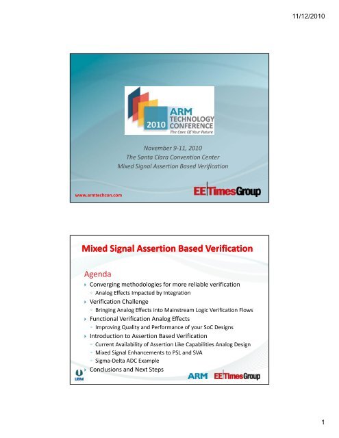
Mixed Signal Assertion Based Verification - Cadence Design Systems
Mixed Signal Assertion Based Verification - Cadence Design Systems
Mixed Signal Assertion Based Verification - Cadence Design Systems
You also want an ePaper? Increase the reach of your titles
YUMPU automatically turns print PDFs into web optimized ePapers that Google loves.
www.armtechcon.com<br />
Agenda<br />
November 9‐11, 2010<br />
The Santa Clara Convention Center<br />
<strong>Mixed</strong> <strong>Signal</strong> <strong>Assertion</strong> <strong>Based</strong> <strong>Verification</strong><br />
<strong>Mixed</strong> <strong>Signal</strong> <strong>Assertion</strong> <strong>Based</strong> <strong>Verification</strong><br />
Converging methodologies for more reliable verification<br />
◦ Analog Effects Impacted by Integration<br />
<strong>Verification</strong> Challenge<br />
◦ Bringing Analog Effects into Mainstream Logic <strong>Verification</strong> Flows<br />
Functional <strong>Verification</strong> Analog Effects<br />
◦ Improving Quality and Performance of your SoC <strong>Design</strong>s<br />
IIntroduction t d ti tto A<strong>Assertion</strong> ti B<strong>Based</strong> dV<strong>Verification</strong> ifi ti<br />
◦ Current Availability of <strong>Assertion</strong> Like Capabilities Analog <strong>Design</strong><br />
◦ <strong>Mixed</strong> <strong>Signal</strong> Enhancements to PSL and SVA<br />
◦ Sigma‐Delta ADC Example<br />
Conclusions and Next Steps<br />
11/12/2010<br />
1
Converging Methodologies for More Reliable<br />
<strong>Verification</strong><br />
Bring <strong>Verification</strong> as a Methodology to Analog<br />
In this presentation we will talk about the potential impact<br />
and benefits of assertion based methodologies on analog<br />
mixed signal designs<br />
Is there a place for it and how can the industry move forward<br />
to leverage the benefits of portability, infrastructure and<br />
visibility into your design status that has been achieved with<br />
digital verification<br />
It will not cover every aspect of your analog verification needs<br />
and there will still be gaps closing on the specifications;<br />
however there will be immediate gains in SoC integration of<br />
analog designs<br />
Converging Methodologies for More Reliable<br />
<strong>Verification</strong> –Why Why Change?<br />
Hardware keeps up with complexity<br />
No productivity improvements gained<br />
Memory Speeds<br />
Enabled multi-core for SPICE, RF<br />
Simulation<br />
Analog effects impacting integration<br />
•High speed I/O sensistivity<br />
•Power startup/shutdown<br />
•Audio-video Fidelity<br />
Can breakdown on integration<br />
•Require continuous verification to<br />
analog design intent<br />
Wikipedia Moore’s Law Image<br />
11/12/2010<br />
2
Analog Effects Into Logic <strong>Verification</strong><br />
On Team Enables That Today<br />
<strong>Verification</strong> Team<br />
<strong>Mixed</strong>-signal <strong>Verification</strong><br />
Specification<br />
<strong>Mixed</strong>-signal <strong>Verification</strong><br />
Model Development<br />
Top Level<br />
Test Bench<br />
Validation<br />
Release to Foundry<br />
Simulation Plan<br />
Top Level Test Bench<br />
Agree?<br />
Agree?<br />
A Agree? ?<br />
Template<br />
GUI<br />
<strong>Design</strong> Team<br />
<strong>Design</strong><br />
Specification<br />
Detailed Circuit<br />
<strong>Design</strong><br />
Full Chip<br />
<strong>Design</strong><br />
Analog Effects Into Logic <strong>Verification</strong><br />
Different Input and Analysis<br />
Templates / <strong>Assertion</strong>s / Multiple Multiple Disciplines Disciplines<br />
Model Code<br />
w/assertions<br />
November 12, 2010 <strong>Cadence</strong><br />
Confidential 5<br />
<strong>Assertion</strong><br />
Diagnostic<br />
Log file<br />
<strong>Cadence</strong> Confidential: <strong>Cadence</strong><br />
Internal Use Only 6<br />
11/12/2010<br />
3
Analog Effects Suitable for Methodology<br />
<strong>Cadence</strong> RFKit<br />
•Implemented Implemented Functional<br />
<strong>Verification</strong> <strong>Design</strong> Flow<br />
<strong>Cadence</strong> RFKit<br />
•Functional verification<br />
models<br />
•<strong>Assertion</strong>s applied to<br />
blocks<br />
Analog Effects Suitable for <strong>Assertion</strong>s<br />
RFKit Application of <strong>Assertion</strong>s<br />
<strong>Assertion</strong>s go with block for validation while blocks integrated<br />
<strong>Assertion</strong>s leveraged in RFKit<br />
◦ Power supply and ground variation<br />
◦ Power down signal change<br />
◦ Supply resistance connected to supply changes<br />
◦ Gain variation at the output as the gain control voltage changes<br />
11/12/2010<br />
4
Spe<br />
c<br />
Introduction to <strong>Assertion</strong> <strong>Based</strong><br />
<strong>Verification</strong><br />
•Simulation<br />
•HW HW Acceleration<br />
•Emulation<br />
A A A<br />
A<br />
A<br />
A AA<br />
Module / Block<br />
A<br />
A A A A<br />
A<br />
A<br />
A A AA<br />
A<br />
A A A A<br />
A A<br />
A<br />
A A<br />
A A<br />
A<br />
A A<br />
A<br />
A A A<br />
A<br />
A A<br />
A A A<br />
A<br />
A<br />
A AA<br />
A A<br />
A<br />
A A<br />
A<br />
A<br />
A<br />
A<br />
A<br />
A<br />
A<br />
A<br />
A<br />
Top-level Integrated <strong>Design</strong><br />
A A<br />
A<br />
A A<br />
A<br />
A<br />
A<br />
A<br />
A<br />
Integrated Blocks<br />
•Formal Analysis<br />
ABV Debugging<br />
•Formal Analysis<br />
•Hybrid<br />
•Simulation<br />
Improve documentation<br />
Improved observability<br />
◦ Id Identifies tifi errors where h th they<br />
take place instead of at the<br />
outputs<br />
◦ Monitors behavior for all<br />
vectors<br />
Improved controllability<br />
Improved coverage<br />
ABV enables a comprehensive verification approach<br />
Select <strong>Assertion</strong> -> Select Waveform Icon<br />
Location of failures are<br />
highlighted in red<br />
<strong>Verification</strong> starts sooner<br />
November 12, 2010 <strong>Cadence</strong><br />
Confidential: <strong>Cadence</strong> Internal Use<br />
Only 9<br />
<strong>Assertion</strong><br />
state is<br />
added to<br />
waveform<br />
November 12, 2010 <strong>Cadence</strong><br />
Confidential: <strong>Cadence</strong> Internal Use<br />
Only 10<br />
11/12/2010<br />
5
ABV with Simvision Simvision: : Go To Cause<br />
Go to Cause finds the assignment<br />
of a signal transition in the waveform<br />
1 Set the time cursor<br />
// GENERIC VERILOGAMS ASSERTION CHECK MACROS:<br />
// This macro prints a message and sets an error flag when the Val is<br />
// too small or too large, and prints an OK message and unsets the error<br />
// flag when it returns to normal operating range. Note that it executes<br />
// Td (seconds) after a crossing event occurs, so that shorter glitches<br />
// will be ignored. First test is performed at time Td. Only difference<br />
// between analog & discrete version is the @() line which defines when<br />
// to repeat the test. Note that the En indicates checking status, not<br />
// operational status, so disabled just means do no checking (error flags<br />
// will stay in "OK" state).<br />
// ARGUMENT LIST:<br />
// Val = input value to check<br />
// Max,Min= validity range of Val. Prints message when out‐of‐range.<br />
// Desc = quoted text for the message ‐ prints as: "{Desc} is too high"<br />
2 Select the signal of choice<br />
3 Use the right mouse button pop-up<br />
menu and select Go to Cause<br />
<strong>Assertion</strong>s Using Behavioral Language<br />
November 12, 2010 <strong>Cadence</strong><br />
Confidential: <strong>Cadence</strong> Internal Use<br />
Only 11<br />
<strong>Mixed</strong>‐signal <strong>Mixed</strong> signal // Name languages = quoted text such for value as Verilog‐A/MS Verilog info ‐ prints A/MS as: "{Name} can = be {Val}" used to create monitoring<br />
// Flg = register or integer to hold state (1=error, 0=OK or not enabled)<br />
models // En = input flag to enable assertion checking: 0 means stop checking.<br />
// Td = time delay between event and check; also analog cross time tol.<br />
// Vtol = crossing voltage tolerance (analog form only)<br />
◦ Requires some level of modeling expertise and understanding of mixed‐signal simulation<br />
semantics `define ACHECK(Val,Max,Min,Desc,Name,Flg,En,Td,Vtol) \<br />
reg Flg=1'b0; \<br />
◦ Generally relies always begin on ‘if \ (expr) $display “msg”’ approach<br />
if (En===1'b0) begin \<br />
Flg
PSL <strong>Mixed</strong> <strong>Signal</strong> <strong>Assertion</strong>s<br />
PSL is language agnostic, which means<br />
◦ PSL can be embedded into Verilog‐AMS<br />
◦ PSL boolean expressions can contain mixed‐signal expressions<br />
electrical int_node, int_node2;<br />
reg clk;<br />
...<br />
...<br />
// psl mixed_signal_check:<br />
// assert always (clk ‐> next(V(int_node2) < 0.6))<br />
@(cross(V(int_node) ‐ 1.25));<br />
Focus for <strong>Cadence</strong> with PSL‐AMS<br />
◦ Allow analog and mixed‐signal expressions in PSL boolean expression layer<br />
when present in Verilog‐AMS<br />
Limited to analog quantities that are currently allowed in the always block in Verilog‐<br />
AMS<br />
◦ Allow external binding of mixed‐signal verification module via vunit<br />
November 12, 2010 <strong>Cadence</strong><br />
Confidential: <strong>Cadence</strong> Internal Use<br />
Only 13<br />
<strong>Mixed</strong> <strong>Signal</strong> <strong>Assertion</strong>s – SystemVerilog<br />
Background<br />
◦ SVA is a legal subset of the SystemVerilog P1800‐2009 P1800 2009 standard<br />
SystemVerilog language does not include AMS yet<br />
◦ SystemVerilog‐AMS language is in the works at IEEE<br />
However, mixed‐signal content can still be brought into<br />
SystemVerilog via real valued port connection<br />
November 12, 2010 <strong>Cadence</strong><br />
Confidential: <strong>Cadence</strong> Internal Use<br />
Only 14<br />
11/12/2010<br />
7
SystemVerilog Cross Domain Connectivity<br />
SystemVerilog testbench driven methodology<br />
◦ 3 classes of connectivity supported:<br />
Data and net types between Verilog‐2001 and Verilog‐AMS objects<br />
SV Real Variable to Verilog‐AMS Electrical –insertion of E2R connect<br />
module<br />
SV Real Variable to Verilog‐AMS WReal – direct connection by<br />
`include "discipline.h"<br />
module ams_src(e);<br />
output e;<br />
electrical e;<br />
analog V(e) 0.5;<br />
endsequence<br />
sva_opcheck1 : assert property (@(posedge clk) S1);<br />
`include "discipline.h"<br />
module ams_dest(w);<br />
input w;<br />
wreal w;<br />
initial<br />
$display("%M: %f", w);<br />
endmodule<br />
November 12, 2010 <strong>Cadence</strong><br />
Confidential: <strong>Cadence</strong> Internal Use<br />
Only 15<br />
November 12, 2010 <strong>Cadence</strong><br />
Confidential: <strong>Cadence</strong> Internal Use<br />
Only 16<br />
11/12/2010<br />
8
Leveraging <strong>Assertion</strong>s In an ADC<br />
Capturing p gSpecification p of Sequential q Behavior<br />
ADC’s, DAC’s, Switch Cap Filters, Serdes good candidates<br />
◦ Specification of circuits contains sequential behavior<br />
ADC example the following behavior is verified<br />
◦ Integrator behavior<br />
◦ Comparator Operations<br />
◦ Loop Stability Fundamentals<br />
ADC Architecture Representation<br />
Sigma Delta Architecture<br />
◦ Modulator and Filter<br />
Modulator with Integrator<br />
Feedback<br />
Filter<br />
11/12/2010<br />
9
ADC PSL Checking Basic Functionality<br />
Integrator Functionality<br />
◦ The sign of the integrator preserved positive cycle<br />
and negative cycle<br />
◦ First assertions leverages internally generated<br />
VerilogAMS values<br />
ADC PSL Checking Sequential Bit Patterns<br />
Modulator Stability<br />
◦ Checking for the presence of undesirable bit<br />
patterns<br />
◦ Repeating bit patterns leading to audible<br />
tones/clicks<br />
11/12/2010<br />
10
ADC PSL Viewing the Results<br />
<strong>Assertion</strong> Browser vs. Waveforms<br />
You be the judge…<br />
<strong>Mixed</strong> <strong>Signal</strong> <strong>Assertion</strong> <strong>Based</strong> <strong>Verification</strong><br />
Is <strong>Assertion</strong> <strong>Based</strong> <strong>Verification</strong> Applicable pp to<br />
<strong>Mixed</strong> <strong>Signal</strong> <strong>Design</strong>s?<br />
ADC’s, DAC’s, Switch Cap Filters, Serdes good candidates<br />
ADC Example Demonstrated <strong>Verification</strong> of Key Behavior<br />
◦ Integrator behavior<br />
◦ Comparator Operations<br />
◦ Loop SStability bili Fundamentals d l<br />
Technology Exists Today to Augment Existing Methodologies<br />
with <strong>Assertion</strong> <strong>Based</strong> <strong>Verification</strong><br />
11/12/2010<br />
11


