

Simple and Efficient Reverse Polarity Protection for -48V ...
Simple and Efficient Reverse Polarity Protection for -48V ...
Simple and Efficient Reverse Polarity Protection for -48V ...

You also want an ePaper? Increase the reach of your titles
YUMPU automatically turns print PDFs into web optimized ePapers that Google loves.
THE POWER MANAGEMENT LEADER<br />
By Goran Stojcic, International Rectifier<br />
INTRODUCTION<br />
<strong>Reverse</strong> polarity protection is required in many -<strong>48V</strong> wired <strong>and</strong><br />
wireless communication infrastructure systems, with or without<br />
two-feed redundancy. <strong>Reverse</strong> polarity protection protects<br />
against accidental swap of ground <strong>and</strong> -<strong>48V</strong> feeds during<br />
system installation that could damage the system or bring down<br />
multiple systems in a central office. The reverse polarity<br />
protection can be implemented either on-board, or at the input<br />
of a custom, multiple-output redundant power supply.<br />
REVERSE POLARITY PROTECTION USING SCHOTTKY DIODE<br />
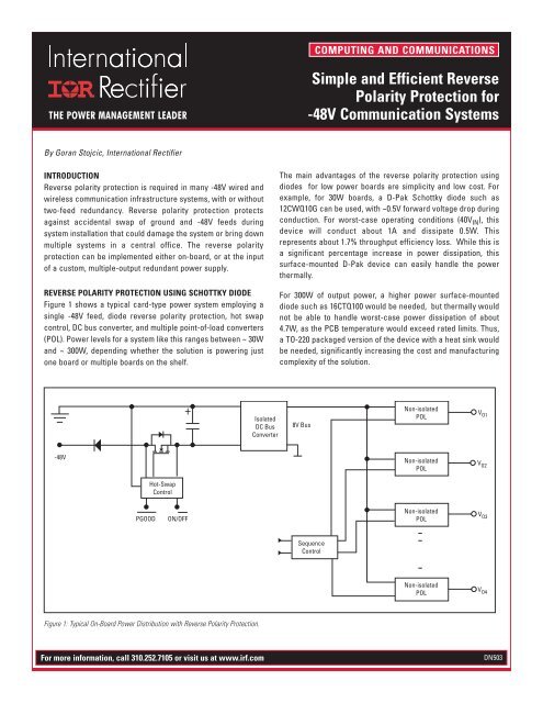
Figure 1 shows a typical card-type power system employing a<br />
single -<strong>48V</strong> feed, diode reverse polarity protection, hot swap<br />
control, DC bus converter, <strong>and</strong> multiple point-of-load converters<br />
(POL). Power levels <strong>for</strong> a system like this ranges between ~ 30W<br />
<strong>and</strong> ~ 300W, depending whether the solution is powering just<br />
one board or multiple boards on the shelf.<br />
-<strong>48V</strong><br />
Hot-Swap<br />
Control<br />
PGOOD ON/OFF<br />
Figure 1: Typical On-Board Power Distribution with <strong>Reverse</strong> <strong>Polarity</strong> <strong>Protection</strong>.<br />
+<br />
Isolated<br />
DC Bus<br />
Converter<br />
COMPUTING AND COMMUNICATIONS<br />
<strong>Simple</strong> <strong>and</strong> <strong>Efficient</strong> <strong>Reverse</strong><br />
<strong>Polarity</strong> <strong>Protection</strong> <strong>for</strong><br />
-<strong>48V</strong> Communication Systems<br />
The main advantages of the reverse polarity protection using<br />
diodes <strong>for</strong> low power boards are simplicity <strong>and</strong> low cost. For<br />
example, <strong>for</strong> 30W boards, a D-Pak Schottky diode such as<br />
12CWQ10G can be used, with ~0.5V <strong>for</strong>ward voltage drop during<br />
conduction. For worst-case operating conditions (40V IN ), this<br />
device will conduct about 1A <strong>and</strong> dissipate 0.5W. This<br />
represents about 1.7% throughput efficiency loss. While this is<br />
a significant percentage increase in power dissipation, this<br />
surface-mounted D-Pak device can easily h<strong>and</strong>le the power<br />
thermally.<br />
For 300W of output power, a higher power surface-mounted<br />
diode such as 16CTQ100 would be needed, but thermally would<br />
not be able to h<strong>and</strong>le worst-case power dissipation of about<br />
4.7W, as the PCB temperature would exceed rated limits. Thus,<br />
a TO-220 packaged version of the device with a heat sink would<br />
be needed, significantly increasing the cost <strong>and</strong> manufacturing<br />
complexity of the solution.<br />
For more in<strong>for</strong>mation, call 310.252.7105 or visit us at www.irf.com DN503<br />
8V Bus<br />
Sequence<br />
Control<br />
Non-isolated<br />
POL<br />
Non-isolated<br />
POL<br />
Non-isolated<br />
POL<br />
Non-isolated<br />
POL<br />
V O1<br />
V O2<br />
V O3<br />
V O4
SIMPLE AND EFFICIENT REVERSE POLARITY PROTECTION FOR -<strong>48V</strong> COMMUNICATION SYSTEMS<br />
REVERSE POLARITY PROTECTION USING<br />
ELECTRONIC CIRCUIT BREAKERS<br />
In higher power custom power supplies (500W to several kW),<br />
Schottky diodes are not practical <strong>for</strong> reverse polarity protection<br />
due to very high power dissipation. Instead, electronic circuit<br />
breakers are used in conjunction with a high power shunt diode<br />
as shown in Figure 2. If the polarity is correct <strong>and</strong> circuit<br />
breaker is on, the current will flow from GND terminal to - <strong>48V</strong><br />
terminal. If the polarity was reversed, the shunt diode will<br />
immediately turn on, <strong>and</strong> the resulting short-circuit current will<br />
quickly trip the circuit breaker off.<br />
While this scheme is lossless, the associated cost is very high<br />
<strong>and</strong> the accuracy of the circuit breakers is not adequate <strong>for</strong><br />
precise current limiting. Required manual reset of the circuit<br />
breaker is also not suitable <strong>for</strong> installation in remote facilities<br />
potentially reducing critical up-time requirements.<br />
REVERSE POLARITY PROTECTION USING<br />
ACTIVE ORING CONTROLLERS.<br />
A much more elegant solution <strong>for</strong> reverse polarity protection is<br />
shown in Figure 3. In this scheme, IR5001S Active ORing<br />
controller is used in conjunction with a power MOSFET to<br />
achieve very efficient <strong>and</strong> simple reverse polarity protection<br />
(the circuit breaker function, if needed, can be achieved with<br />
various industry-st<strong>and</strong>ard hot-swap controllers).<br />
IR5001S operation is automatic; if the polarity at the input<br />
terminals is right, the IC will be properly biased <strong>and</strong> will turn the<br />
reverse polarity FET on. If the polarity is reversed, the IC itself<br />
0.1µF<br />
-<strong>48V</strong><br />
V LINE<br />
V CC<br />
FETst<br />
IR5001S<br />
FETch<br />
V OUT<br />
- <strong>48V</strong><br />
Figure 3: <strong>Reverse</strong> <strong>Polarity</strong> <strong>Protection</strong> Using IR5001S Active ORing Controller <strong>and</strong> Power MOSFET.<br />
Gnd<br />
INN<br />
INP<br />
For more in<strong>for</strong>mation, call 310.252.7105 or visit us at www.irf.com<br />
Isolated-<br />
Multiple<br />
Output<br />
DC/DC<br />
Converter<br />
Figure 2: <strong>Reverse</strong> <strong>Polarity</strong> <strong>Protection</strong> using Electronic Circuit Breaker <strong>and</strong> a Diode.<br />
will not have the proper bias <strong>and</strong> it will remain off, thus<br />
preventing the reverse polarity MOSFET from turning on.<br />
IR5001S requires only a small bias capacitor <strong>for</strong> proper<br />
operation, but does offer several interesting features (including<br />
a system diagnostics capability). The details are described at<br />
http://www.irf.com/product-info/datasheets/data/IR5001S.pdf.<br />
Compared to the scheme shown in Figure 2, IR5001S used in<br />
conjunction with the IRF6644 100V DirectFET MOSFET, reduces<br />
power dissipation from ~4.7W to only 0.7W. This is more than sixfold<br />
power loss reduction. For a 200W boards, power loss<br />
reduction with the same MOSFET would be tenfold!<br />
For multiple-output power supplies in 1kW range, IR5001S can be<br />
used in conjunction with two D2-Pak IRFS4310PbF in parallel to<br />
reduce power dissipation of the reverse polarity protection<br />
function to less than 0.3% of the output power. This is significantly<br />
lower than 1.7% with diode ORing, <strong>and</strong> much less expensive than<br />
using traditional circuit breakers.<br />
D TZ<br />
+<br />
C IN<br />
DirectFET is a trademark of International Rectifier.<br />
Isolated<br />
DC-DC<br />
Converter


