Instructions for: Diesel eNGiNe settiNG / lockiNG ... - Tooled-Up.com
Instructions for: Diesel eNGiNe settiNG / lockiNG ... - Tooled-Up.com
Instructions for: Diesel eNGiNe settiNG / lockiNG ... - Tooled-Up.com

Create successful ePaper yourself
Turn your PDF publications into a flip-book with our unique Google optimized e-Paper software.
1. sAFety iNstrUctioNs<br />
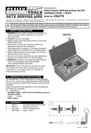
<strong>Instructions</strong> <strong>for</strong>:<br />
<strong>Diesel</strong> <strong>eNGiNe</strong> <strong>settiNG</strong> / <strong>lockiNG</strong><br />
tool kit chrysler 2.5crD <strong>eNGiNe</strong>s<br />
Model No: Vs4945<br />
Thank you <strong>for</strong> purchasing a Sealey product. Manufactured to a high standard this product will, if used according to these instructions<br />
and properly maintained, give you years of trouble free per<strong>for</strong>mance.<br />
IMPORTANT: PleAse reAD these iNstrUctioNs cAreFUlly. Note the sAFe oPerAtioNAl reQUireMeNts, WArNiNGs AND cAUtioNs.<br />
Use the ProDUct correctly AND With cAre For the PUrPose For Which it is iNteNDeD. FAilUre to Do so MAy cAUse DAMAGe<br />
AND/or PersoNAl iNJUry AND Will iNVAliDAte the WArrANty. PleAse keeP iNstrUctioNs sAFe For FUtUre Use.<br />
WArNiNG! Ensure Health and Safety, local authority and general<br />
workshop practice regulations are adhered to when using tools.<br />
Do Not use tools if damaged.<br />
Maintain tools in good and clean condition <strong>for</strong> best and safest<br />
per<strong>for</strong>mance.<br />
Ensure that a vehicle which has been jacked up is adequately<br />
supported with axle stands.<br />
Wear approved eye protection. A full range of personal safety<br />
equipment is available from your Sealey dealer.<br />
Wear suitable clothing to avoid snagging. Do not wear jewellery and<br />
tie back long hair.<br />
Account <strong>for</strong> all tools, locking bolts, pins and parts being used and do<br />
not leave them in or near the engine.<br />
WArNiNG! Incorrect or out of phase camshaft timing can result in<br />
contact between valve head and piston crown causing damage to the<br />
engine.<br />
IMPORTANT: These instructions are provided as a guide only. Always<br />
refer to the vehicle manufacturer’s service instructions, or a proprietary<br />
manual, to establish the current procedure and data.<br />
WARNING: The warnings, cautions and instructions discussed in<br />
this manual cannot cover all possible conditions and situations<br />
that may occur. It must be understood that <strong>com</strong>mon sense and<br />
caution are factors which cannot be built into this product, but<br />
must be applied by the operator.<br />
2. iNtroDUctioN & APPlicAtioNs<br />
Setting and locking kit <strong>for</strong> 2.5 VM engine found in Chrysler and LDV<br />
vehicles. This engine has variants both with and without balancer shafts<br />
and this kit covers both applications. The kit includes flywheel, camshaft<br />
and balancer locking pins plus a tensioner adjustment tool.<br />
chrysler 2.5crD <strong>Diesel</strong> engines in<br />
chrysler<br />
Voyager Grand Voyager<br />
lDV<br />
Maxus<br />
engine codes:<br />
R2516C / R2516L engines<br />
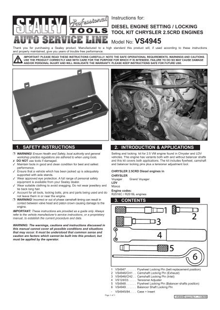
3. coNteNts<br />
1 VS4947 ...... Flywheel Locking Pin (belt replacement position)<br />
2 VS4946/CH1 .. Camshaft Locking Pin (Exhaust)<br />
3 VS4946/CH2 .. Camshaft Locking Pin (Inlet)<br />
4 VS124/03. .... Tensioner Adjuster<br />
5 VS4948 ...... Flywheel Locking Pin (Balancer shafts position)<br />
6 VS4949 . ..... Balancer Shaft Locking Pin<br />
- VS4945/84. ... Case + Insert<br />
Page 1 of 3<br />
VS4945 Issue No:1 - 11/06/08
4. iNstrUctioNs<br />
4.1 timing Belt replacement<br />
It will be necessary to remove the timing belt cover and air filter<br />
assembly.<br />
Support the engine and remove the right-hand splashguard and engine<br />
undersheild.<br />
Remove the right-hand engine mounting, the auxiliary belt, its tensioner<br />
and the starter motor.<br />
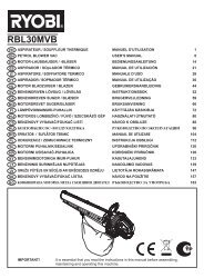
remove the crankshaft pulley<br />
Fig.1<br />
4.2 Vs4947 Flywheel locking Pin<br />
4.2.1 Turn the engine clockwise until the timing mark on the crankshaft<br />
gear is at the 3-0-clock position – engine at 90° A.t.D.c. and ‘lock’ the<br />
flywheel using VS4947 Locking Pin. (Fig.1)<br />
iMPortANt: Ensure that the VS4947 Locking Pin has fully<br />
entered into the flywheel.<br />
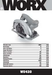
inlet camshaft<br />
Fig.2a<br />
Page 2 of 3<br />
exhaust camshaft<br />
4.2.2 VS4946 / CH1 (Exhaust) and VS4946 / CH2 (Inlet) Camshaft<br />
Locking Pins.<br />
Fig.2b<br />
Note: VS4946/CH1 Locking Pin is smaller than CH2 in order to avoid<br />
obstructions around its entry hole in the cylinder head cover. Ensure that<br />
Pin CH1 is used <strong>for</strong> locking the exhaust camshaft.<br />
Remove the blanking plugs in the cylinder head cover and insert<br />
VS4946/CH1 into the exhaust camshaft (Fig.2b) and VS4946/CH2 into<br />
the inlet camshaft. (Fig.2a)<br />
WArNiNG: take care not to over-tighten the camshaft locking Pins.<br />
there are only 3 threads in the cylinder head cover where these<br />
Pins enter and over-tightening could ‘strip’ these threads.<br />
Note: If the Camshaft Locking Pins will not locate into the camshafts,<br />
remove VS4947 Flywheel Locking Pin and rotate the engine 360°. Re-fit<br />
the Flywheel Pin and insert the Camshaft Locking Pins.<br />
Check that the fuel pump timing mark is aligned with the mark on the<br />
back cover.<br />
Slacken the camshaft sprocket bolts whilst counter-holding the sprockets<br />
with a suitable Sprocket Holding Tool.<br />
Undo the belt tensioner bolt and move the tensioner pulley away from the<br />
belt and remove the timing belt.<br />
4.2.3 Fitting the new belt<br />
Check that the Flywheel and Camshaft Locking Pins are correctly<br />
inserted.<br />
Fit new bolts in the camshaft sprockets and tighten to finger-tight only.<br />
Check that the fuel pump timing marks are aligned.<br />
Fit the new belt onto the crankshaft gear and then in an anti-clockwise<br />
direction fit to fuel pump, belt guide, inlet camshaft sprocket, exhaust<br />
camshaft sprocket, belt guide, coolant pump and belt tensioner.<br />
Using a suitable Sprocket Holding Tool, turn the inlet camshaft<br />
sprocket slightly anti-clockwise, to remove slack in the timing belt.<br />
VS4945 Issue No:1 - 11/06/08
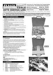
Fig.3<br />
4.2.4 Vs124/03 Belt tensioner Adjuster<br />
Fit VS124/03 Tensioner Adjuster into the two holes in the tensioner pulley<br />
and turn it clockwise until the ‘notch’ on the pointer is aligned with the<br />
dowel pin, and tighten the pulley bolt. (Fig.3).<br />
Counter-hold the camshaft sprockets with a suitable Sprocket Holding<br />
Tool and tighten each of the sprocket bolts to 108 Nm.<br />
Remove the Flywheel and Camshaft Locking Pins.<br />
4.2.5 Check the engine timing by making a small paint mark on the<br />
timing belt and adjacent cover.<br />
Rotate the crankshaft clockwise until the mark returns to its<br />
original position, and insert VS4947 Flywheel Locking Pin.<br />
Check that the CH1 and CH2 Camshaft Locking Pins will enter<br />
and that the tensioner pointer is in the correct position.<br />
4.3 Balancer shafts<br />
The balancer shafts are housed in an aluminium carrier, mounted to the<br />
engine block.<br />
NOTE: It is our policy to continually improve products and as such we reserve the right to alter data, specifications and <strong>com</strong>ponent parts without prior notice.<br />
iMPortANt: No liability is accepted <strong>for</strong> incorrect use of this product.<br />
WArrANty: Guarantee is 12 months from purchase date, proof of which will be required <strong>for</strong> any claim.<br />
iNForMAtioN: For a copy of our latest catalogue and promotions call us on 01284 757525 and leave your full name and address, including<br />
postcode.<br />
sole Uk Distributor<br />
sealey Group,<br />
Bury St. Edmunds, Suffolk.<br />
Page 3 of 3<br />
Fig.4<br />
4.3.1 Vs4948 Flywheel locking Pin (Balancer shaft)<br />
If the balancer shaft assembly has been removed, No. 1 cylinder must<br />
be positioned at TDC and VS4948 Flywheel Locking Pin inserted to ‘lock’<br />
the flywheel, be<strong>for</strong>e the assembly can be installed. (Fig.4).<br />
Fig.5<br />
4.3.2 Vs4949 Balancer shaft locking Pin<br />
Whilst the balancer shaft assembly is out of the engine, VS4949 Locking<br />
Pin can be inserted to ensure that the balancer shaft and crankshaft<br />
timing is correct after assembly. (Fig.5)<br />
01284 757500<br />
Web<br />
www.sealey.co.uk<br />
01284 703534 email sales@sealey.co.uk<br />
VS4945 Issue No:1 - 11/06/08