491 Locks - Häfele
491 Locks - Häfele 491 Locks - Häfele
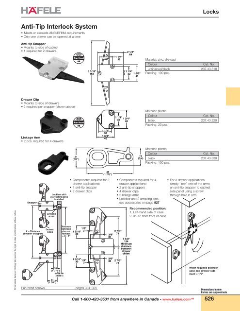
Dimensional data not binding. We reserve the right to alter specifications without notice. Anti-Tip Interlock System • Meets or exceeds ANSI/BFIMA requirements • Only one drawer can be opened at a time Anti-tip Snapper • Mounts to side of cabinet • 1 required for 2 drawers Drawer Clip • Mounts to side of drawers • 2 required per snapper (shown above) Linkage Arm • 2 pcs. required for 4 drawers Snapper X = Distance between snappers Lockbar with 2 arresting pins installed Linkage arms Drawer Clips 18 (11/16") 18 (11/16") 44 (1 3/4") Distance between pins on lockbar = X - 1" Pan Head #8 Pan Head #8 21 (7/8") 1 3/16" 30 1 3/16" 30 1/8" 3 1/8" 3 6 1/16" 152 Pan head screws pages 304–305 1 1/4" 32 1 3/4" 46 48 (1 7/8") • Components required for 2 drawer applications: • 1 anti-tip snapper • 2 drawer clips 1 3/8" 35 1 1/4" 32 1 1/4" 32 1 3/8" 35 2 7/8" 73 • Components required for 4 drawer applications: • 2 anti-tip snappers • 4 drawer clips • 2 linkage arms • Lockbar and 2 arresting pins - see accessories on page 527 2 7/8" 73 2 1/2" 64 1 1/4" 32 1 5/8" 41 1 3/4" 46 7 5/8" 194 Minimum distance between drawer slides 19 (3/4) Call 1-800-423-3531 from anywhere in Canada - www.hafele.com Locks Material: zinc, die-cast Colour Cat. No. unfinished/black 237.43.310 Packing: 100 pcs. Material: plastic Colour Cat. No. black 237.43.320 Packing: 20 pcs. Material: plastic Colour Cat. No. black 237.43.330 Packing: 100 pcs. Recommended position: 1. Left-hand side of case 2. 3"– 5" from front of case • For 3 drawer applications simply “lock” one of the arms on anti-tip snapper to cabinet side panel using a screw through hole in arm. Width required between case and drawer side must = 1/2" Dimensions in mm Inches are approximate 526
Cylinder Module System Accessories L Lockbar, for use with any central locking assembly from the cylinder module system. Lockbar groove is 11/16” wide x 5/32” deep. J Arresting pins Hexagonal section, for installation in lockbar L , using combination tool, at any desired position. K Dimensions in mm Inches are approximate Bar Retaining Bracket, with guide lug 527 Pan Head #6 66 (2 5/8”) 55 32 3.5 (1/8”) 16.5 (11/16”) Length 16.5 ø7 11 (7/16”) 1 1.5 Locks Material: steel Length zinc-plated 457 mm (18") 234.87.818 609 mm (24") 234.87.827 915 mm (36") 234.87.836 1220 mm (48") 234.87.845 Packing: 1 pc. Material: Pin: steel Wing screw and lock washer: steel Length nickel-plated/black Packing 9.5 mm (3/8”) 237.22.714 100 pcs. 13 mm (1/2”) 237.22.723 100 pcs. 16 mm (5/8”) 237.22.732 100 pcs. 19 mm (3/4”) 237.22.741 500 pcs. 22 mm (7/8”) 237.22.750 100 pcs. 25 mm (1”) 237.22.769 100 pcs. 32 mm (1 1/4”) 237.22.778 100 pcs. 38 mm (1 1/2”) 237.22.787 100 pcs. 51 mm (2”) 237.22.796 100 pcs. Material: steel Colour Cat. No. zinc-plated 234.87.989 Packing: 100 pcs. Combination Tool To install arresting pins J in lockbar L . In addition to the hexagon head, the tool incorporates a notched sleeve which engages the square lug in the cylinder housing, enabling any lock in the module system to be operated before the cylinder core is installed. Material: hardened steel, nickel-plated Handle: plastic, clear/red Cat. No. 006.36.653 Packing: 1 pc. Special-purpose drill bit - Ø 16.5 mm Suitable for any cylinder housing in the system. Can also be used in clockwise multi-spindle drilling machines with 10 mm chuck. Material: Shank: steel Bit: carbide-tipped Cat. No. 001.24.194 Packing: 1 pc. Pan head screws pages 304–305 Call 1-800-423-3531 from anywhere in Canada - www.hafele.com Dimensional data not binding. We reserve the right to alter specifications without notice.
- Page 1 and 2: 491 Locks Locking Systems - Overvie
- Page 3 and 4: Locking Systems - Overview Häfele
- Page 5 and 6: Decorative Keys Lever Bit The desir
- Page 7 and 8: SYMO 3000 Locking System Informatio
- Page 9 and 10: SYMO 3000 Dead Bolt Rim Lock Backse
- Page 11 and 12: SYMO 3000 Dead Bolt Rim Lock With e
- Page 13 and 14: SYMO 3000 Inlaid lock, screw-mount
- Page 15 and 16: SYMO 3000 Locking cam, straight Loc
- Page 17 and 18: SYMO 3000 Counterpiece, for glass d
- Page 19 and 20: SYMO 3000 Central locking cylinder
- Page 21 and 22: SYMO 3000 Master key for plate-cyli
- Page 23 and 24: Dimensional data not binding. We re
- Page 25 and 26: Dimensional data not binding. We re
- Page 27 and 28: Dimensional data not binding. We re
- Page 29 and 30: Dimensional data not binding. We re
- Page 31 and 32: Dimensional data not binding. We re
- Page 33 and 34: Central Locking Single Pedestal Sid
- Page 35 and 36: Central Locking Anti-Tip System Cyl
- Page 37: Anti-Tip Interlock System No Lock D
- Page 41 and 42: Accessories Cylinder Module System
- Page 43 and 44: Deadbolt Locks FH Series Deadbolt L
- Page 45 and 46: Tambour and Sliding Door Locks FH S
- Page 47 and 48: Central Locking System FH Series Si
- Page 49 and 50: Cam Locks H Series Cam Lock, with c
- Page 51 and 52: Central Locking System H Series Cen
- Page 53 and 54: Cam Locks 1 1/8" 1/8" Dimensions in
- Page 55 and 56: Cam Locks • Easily converted from
- Page 57 and 58: Cam Locks • Economical drawer loc
- Page 59 and 60: Central Locking System Accessories
- Page 61 and 62: Sliding Door Locks Dimensions in mm
- Page 63 and 64: Sliding Door Locks Glass Door Cylin
- Page 65 and 66: Dimensional data not binding. We re
- Page 67 and 68: Dimensional data not binding. We re
- Page 69 and 70: Dimensional data not binding. We re
- Page 71 and 72: Dimensional data not binding. We re
- Page 73 and 74: Dimensional data not binding. We re
- Page 75 and 76: Dimensional data not binding. We re
- Page 77 and 78: Dimensional data not binding. We re
- Page 79 and 80: Dimensional data not binding. We re
- Page 81 and 82: Dimensional data not binding. We re
- Page 83 and 84: Dimensional data not binding. We re
- Page 85 and 86: Dimensional data not binding. We re
- Page 87 and 88: Dimensional data not binding. We re
Dimensional data not binding. We reserve the right to alter specifications without notice.<br />
Anti-Tip Interlock System<br />
• Meets or exceeds ANSI/BFIMA requirements<br />
• Only one drawer can be opened at a time<br />
Anti-tip Snapper<br />
• Mounts to side of cabinet<br />
• 1 required for 2 drawers<br />
Drawer Clip<br />
• Mounts to side of drawers<br />
• 2 required per snapper (shown above)<br />
Linkage Arm<br />
• 2 pcs. required for 4 drawers<br />
Snapper<br />
X = Distance<br />
between snappers<br />
Lockbar with<br />
2 arresting pins<br />
installed<br />
Linkage<br />
arms<br />
Drawer<br />
Clips<br />
18<br />
(11/16")<br />
18<br />
(11/16")<br />
44<br />
(1 3/4")<br />
Distance<br />
between<br />
pins on<br />
lockbar<br />
= X - 1"<br />
Pan Head<br />
#8<br />
Pan Head<br />
#8<br />
21<br />
(7/8")<br />
1 3/16"<br />
30<br />
1 3/16"<br />
30<br />
1/8"<br />
3<br />
1/8"<br />
3<br />
6 1/16"<br />
152<br />
Pan head screws pages 304–305<br />
1 1/4"<br />
32<br />
1 3/4"<br />
46<br />
48<br />
(1 7/8")<br />
• Components required for 2<br />
drawer applications:<br />
• 1 anti-tip snapper<br />
• 2 drawer clips<br />
1 3/8"<br />
35<br />
1 1/4"<br />
32<br />
1 1/4"<br />
32<br />
1 3/8"<br />
35 2 7/8"<br />
73<br />
• Components required for 4<br />
drawer applications:<br />
• 2 anti-tip snappers<br />
• 4 drawer clips<br />
• 2 linkage arms<br />
• Lockbar and 2 arresting pins -<br />
see accessories on page 527<br />
2 7/8"<br />
73<br />
2 1/2"<br />
64<br />
1 1/4"<br />
32 1 5/8"<br />
41<br />
1 3/4"<br />
46<br />
7 5/8"<br />
194<br />
Minimum<br />
distance<br />
between<br />
drawer<br />
slides<br />
19<br />
(3/4)<br />
Call 1-800-423-3531 from anywhere in Canada - www.hafele.com<br />
<strong>Locks</strong><br />
Material: zinc, die-cast<br />
Colour Cat. No.<br />
unfinished/black 237.43.310<br />
Packing: 100 pcs.<br />
Material: plastic<br />
Colour Cat. No.<br />
black 237.43.320<br />
Packing: 20 pcs.<br />
Material: plastic<br />
Colour Cat. No.<br />
black 237.43.330<br />
Packing: 100 pcs.<br />
Recommended position:<br />
1. Left-hand side of case<br />
2. 3"– 5" from front of case<br />
• For 3 drawer applications<br />
simply “lock” one of the arms<br />
on anti-tip snapper to cabinet<br />
side panel using a screw<br />
through hole in arm.<br />
Width required between<br />
case and drawer side<br />
must = 1/2"<br />
Dimensions in mm<br />
Inches are approximate<br />
526


