Assembly/Disassembly Instruction Sheet - Watson-Marlow
Assembly/Disassembly Instruction Sheet - Watson-Marlow
Assembly/Disassembly Instruction Sheet - Watson-Marlow

Create successful ePaper yourself
Turn your PDF publications into a flip-book with our unique Google optimized e-Paper software.
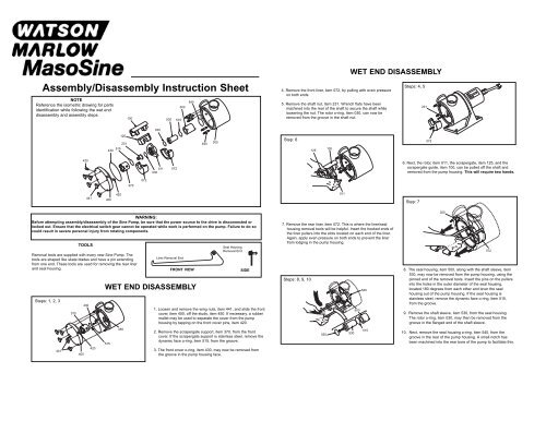
<strong>Assembly</strong>/<strong>Disassembly</strong> <strong>Instruction</strong> <strong>Sheet</strong><br />
NOTE<br />
Reference the isometric drawing for parts<br />
identification while following the wet end<br />
disassembly and assembly steps.<br />
WARNING:<br />
Before attempting assembly/disassembly of the Sine Pump, be sure that the power source to the drive is disconnected or<br />
locked out. Ensure that the electrical switch gear cannot be operated while work is performed on the pump. Failure to do so<br />
could result in severe personal injury from rotating components.<br />
TOOLS<br />
Removal tools are supplied with every new Sine Pump. The<br />
tools are shaped like skate blades and have a pin extending<br />
from one end. These tools are used for removing the rear liner<br />
and seal housing.<br />
Steps: 1, 2, 3<br />
441<br />
370<br />
400<br />
420<br />
430<br />
441<br />
420<br />
231<br />
515<br />
430<br />
400<br />
WET END DISASSEMBLY<br />
515<br />
420<br />
125<br />
450<br />
100<br />
370<br />
072<br />
030<br />
011<br />
030<br />
530<br />
072<br />
515<br />
500<br />
Liner Removal End<br />
540<br />
FRONT VIEW<br />
450<br />
1. Loosen and remove the wing nuts, item 441, and slide the front<br />
cover, item 400, off the studs, item 450. If necessary, a rubber<br />
mallet may be used to separate the cover from the pump<br />
housing by tapping on the front cover pins, item 420.<br />
2. Remove the scrapergate support, item 370, from the front<br />
cover. If the scrapergate support is stainless steel, remove the<br />
dynamic face o-ring, item 515, from the groove.<br />
300<br />
Seal Housing<br />
Removal End<br />
SIDE<br />
3. The front cover o-ring, item 430, may now be removed from<br />
the groove in the pump housing face.<br />
4. Remove the front liner, item 072, by pulling with even pressure<br />
on both ends.<br />
5. Remove the shaft nut, item 231. Wrench flats have been<br />
machined into the rear of the shaft to secure the shaft while<br />
loosening the nut. The rotor o-ring, item 030, can now be<br />
removed from the groove in the shaft nut.<br />
Step: 6<br />
7. Remove the rear liner, item 072. This is where the liner/seal<br />
housing removal tools will be helpful. Insert the hooked ends of<br />
the liner pullers into the slots located on each end of the liner.<br />
Again, apply even pressure on both ends to prevent the liner<br />
from lodging in the pump housing.<br />
Steps: 8, 9, 10<br />
125<br />
030<br />
100<br />
011<br />
WET END DISASSEMBLY<br />
530<br />
500<br />
540<br />
515<br />
Steps: 4, 5<br />
6. Next, the rotor, item 011, the scrapergate, item 125, and the<br />
scrapergate guide, item 100, can be pulled off the shaft and<br />
removed from the pump housing. This will require two hands.<br />
Step: 7<br />
231<br />
072<br />
300<br />
8. The seal housing, item 500, along with the shaft sleeve, item<br />
530, may now be removed from the pump housing, using the<br />
pinned end of the removal tools. Insert the pins on the pullers<br />
into the holes in the outer diameter of the seal housing,<br />
located 180 degrees from each other and lever the seal<br />
housing out of the pump housing. If the seal housing is<br />
stainless steel, remove the dynamic face o-ring, item 515,<br />
from the groove.<br />
9. Remove the shaft sleeve, item 530, from the seal housing.<br />
The rotor o-ring, item 030, may then be removed from the<br />
groove in the flanged end of the shaft sleeve.<br />
10. Next, remove the seal housing o-ring, item 540, from the<br />
groove in the rear of the pump housing. A small notch has<br />
been machined into the rear bore of the pump to facilitate this.<br />
072
1. Lubricate the seal housing o-ring, item 540, with a food grade<br />
grease and insert it into the groove at the rear of the pump<br />
housing.<br />
2. If the seal housing, item 500, is stainless steel, place the<br />
dynamic face o-ring, item 515, into the groove on the the seal<br />
housing face. Again apply a food grade lubricant to the o-ring.<br />
Then place the seal housing over the shaft and into the rear<br />
bore of the pump housing with the removal holes exposed. If<br />
the seal housing is stainless steel, the anti-rotation pin<br />
located at the rear must be properly located into the slot in<br />
the rear of the pump housing.<br />
Step: 3<br />
4. Apply a food grade lubricant to one of the rotor o-rings, item<br />
030, and place it into the groove on the shaft sleeve, item 530.<br />
Next lubricate the O.D. of the sleeve and place it over the shaft<br />
and into the seal housing.<br />
Step 5:<br />
Anti-rotation<br />
pins<br />
300<br />
231<br />
ISO 2806 Original - E<br />
200<br />
011<br />
072<br />
500<br />
WET END ASSEMBLY<br />
540<br />
Steps: 1, 2<br />
3. To properly seat the seal housing, place the rotor, item 011, and<br />
shaft nut, item 231, onto the shaft and tighten the nut until the<br />
seal housing is forced past the seal housing o-ring. Remove<br />
the rotor and shaft nut from the shaft before proceeding.<br />
Step: 4<br />
030<br />
300<br />
515<br />
530<br />
5. Install one of the liners, item 072, into the pump housing and<br />
locate it between the anti-rotation pins on the I.D. of the pump<br />
housing as shown. Apply even pressure at both ends to<br />
prevent the liner from lodging in the pump housing.<br />
500<br />
540<br />
500<br />
540<br />
6. Place the scrapergate, item 125, into the scrapergate guide,<br />
item 100, being sure that the marked ends (SL and SR) match<br />
up properly. See Appendix 2 in the instruction manual for<br />
detailed description of scrapergate/scrapergate guide<br />
orientation. With the scrapergate and guide in the desired<br />
orientation, place the assembly onto the rotor, item 011, fitting<br />
the “slot” over the rotor vane. With two hands, insert the three<br />
piece assembly into the pump by placing the scrapergate guide<br />
into the bore between the nozzles and fitting the rotor over the<br />
splined section of the shaft. Once the rotor meets the o-ring<br />
on the shaft sleeve, apply extra pressure to seat the o-ring<br />
properly.<br />
Steps: 7, 8<br />
231<br />
072<br />
030<br />
9. Apply a food grade lubricant to the front cover o-ring, item<br />
430, and place it into the groove on the pump housing face.<br />
10. If the scrapergate support, item 370, is stainless steel,<br />
lubricate the dynamic face o-ring, item 515, and place it into<br />
the groove on the end of the support. Next, place the<br />
scrapergate support into the center bore of the front cover,<br />
item 400, slotted end first. If the support is stainless steel,<br />
be sure the anti-rotation pins fit into the relief slots in the<br />
cover.<br />
11. Place the front cover and scrapergate support assembly onto<br />
the pump housing by aligning the studs, item 450, with the<br />
corresponding holes in the cover. Front cover pins, item 420,<br />
have been provided to facilitate this.<br />
12. Install the wing nuts, item 441, and hand tighten. The wing<br />
nuts may be tightened further with a rubber mallet.<br />
WET END ASSEMBLY<br />
Step: 6<br />
125<br />
7. Apply a food grade lubricant to the other rotor o-ring, item 030,<br />
and place it into the groove on the shaft nut, item 231. Place<br />
the shaft nut onto the shaft and firmly tighten. Wrench flats<br />
have been machined into the rear of the shaft to secure the<br />
shaft while tightening the nut.<br />
8. Install the remaining liner, item 072, into the pump housing and<br />
locate it between the anti-rotation pins on the I.D. of the pump<br />
housing as shown. Apply even pressure at both ends to<br />
prevent the liner from lodging in the pump housing.<br />
Steps: 9, 10, 11, 12<br />
441<br />
370<br />
100<br />
400<br />
430<br />
011<br />
420<br />
515<br />
450