Replacing the Rotor Seal
Replacing the Rotor Seal
Replacing the Rotor Seal

Create successful ePaper yourself
Turn your PDF publications into a flip-book with our unique Google optimized e-Paper software.
The rotor seal forms a high-pressure seal between <strong>the</strong> stator and <strong>the</strong><br />
rotor. Replace <strong>the</strong> rotor seal when leaking occurs between <strong>the</strong> stator<br />
and <strong>the</strong> stator ring or when you notice a decrease in injection<br />
precision.<br />
Stator<br />
Stator ring<br />
The lot ID sticker on <strong>the</strong> stator ring identifies <strong>the</strong> week and year<br />
(WWYY) of <strong>the</strong> manufacture date.<br />
Injection valves manufactured week 37 of 2008 or later have a<br />
factory-applied, red mark on <strong>the</strong> valve body. The alignment of <strong>the</strong><br />
red mark on <strong>the</strong> valve body and <strong>the</strong> dimple on <strong>the</strong> pressure<br />
adjustment nut corresponds to <strong>the</strong> optimal pressure setting for <strong>the</strong><br />
valve with <strong>the</strong> factory-installed rotor seal. Because <strong>the</strong> optimal<br />
pressure setting depends on <strong>the</strong> rotor seal thickness, it is subject to<br />
change when you replace <strong>the</strong> rotor seal.<br />
The factory-applied red mark on injection valves manufactured<br />
before week 37 of 2008 does not correspond to <strong>the</strong> optimal pressure<br />
setting. You must make your own marks.<br />
To replace <strong>the</strong> rotor seal, follow <strong>the</strong>se procedures:<br />
1. Removing <strong>the</strong> Injection Valve from <strong>the</strong> Autosampler<br />
2. Disassembling <strong>the</strong> Injection Valve<br />
3. Installing a New <strong>Rotor</strong> <strong>Seal</strong><br />
4. Reassembling <strong>the</strong> Injection Valve<br />
5. Reinstalling <strong>the</strong> Valve and Checking for Leaks<br />
Removing <strong>the</strong> Injection Valve from <strong>the</strong> Autosampler<br />
To remove <strong>the</strong> injection valve from <strong>the</strong> autosampler<br />
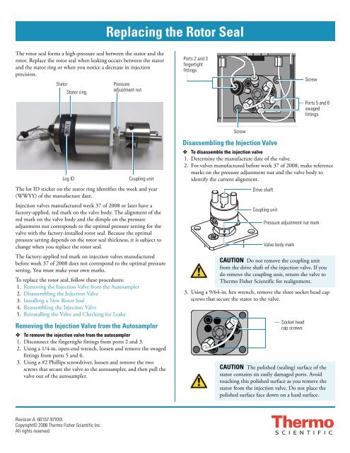
1. Disconnect <strong>the</strong> fingertight fittings from ports 2 and 3.<br />
2. Using a 1/4-in. open-end wrench, loosen and remove <strong>the</strong> swaged<br />
fittings from ports 5 and 6.<br />
3. Using a #2 Phillips screwdriver, loosen and remove <strong>the</strong> two<br />
screws that secure <strong>the</strong> valve to <strong>the</strong> autosampler, and <strong>the</strong>n pull <strong>the</strong><br />
valve out of <strong>the</strong> autosampler.<br />
Revision A 60157-97XXX<br />
Copyright© 2008 Thermo Fisher Scientific Inc.<br />
All rights reserved.<br />
<strong>Replacing</strong> <strong>the</strong> <strong>Rotor</strong> <strong>Seal</strong><br />
Pressure<br />
adjustment nut<br />
Log ID Coupling unit<br />
Ports 2 and 3<br />
fingertight<br />
fittings<br />
Screw<br />
Disassembling <strong>the</strong> Injection Valve<br />
20 µL<br />
2<br />
3 1<br />
4 6<br />
5<br />
Screw<br />
Ports 5 and 6<br />
swaged<br />
fittings<br />
To disassemble <strong>the</strong> injection valve<br />
1. Determine <strong>the</strong> manufacture date of <strong>the</strong> valve.<br />
2. For valves manufactured before week 37 of 2008, make reference<br />
marks on <strong>the</strong> pressure adjustment nut and <strong>the</strong> valve body to<br />
identify <strong>the</strong> current alignment.<br />
Drive shaft<br />
Coupling unit<br />
Pressure adjustment nut mark<br />
Valve body mark<br />
CAUTION Do not remove <strong>the</strong> coupling unit<br />
from <strong>the</strong> drive shaft of <strong>the</strong> injection valve. If you<br />
do remove <strong>the</strong> coupling unit, return <strong>the</strong> valve to<br />
Thermo Fisher Scientific for realignment.<br />
3. Using a 9/64-in. hex wrench, remove <strong>the</strong> three socket head cap<br />
screws that secure <strong>the</strong> stator to <strong>the</strong> valve.<br />
3<br />
2<br />
1<br />
4<br />
5<br />
6<br />
Socket head<br />
cap screws<br />
CAUTION The polished (sealing) surface of <strong>the</strong><br />
stator contains six easily damaged ports. Avoid<br />
touching this polished surface as you remove <strong>the</strong><br />
stator from <strong>the</strong> injection valve. Do not place <strong>the</strong><br />
polished surface face down on a hard surface.
4. Pull <strong>the</strong> stator off <strong>the</strong> valve. Place it on its side on a clean surface.<br />
5. If <strong>the</strong> polished surface of <strong>the</strong> stator is scratched, replace <strong>the</strong> valve.<br />
6. Pull <strong>the</strong> stator ring off <strong>the</strong> valve.<br />
7. Pull <strong>the</strong> rotor seal off <strong>the</strong> three pins on <strong>the</strong> drive shaft.<br />
8. Inspect <strong>the</strong> valve components for contamination. Clean as<br />
necessary.<br />
Installing a New <strong>Rotor</strong> <strong>Seal</strong><br />
To install a new rotor seal<br />
Hold <strong>the</strong> rotor seal with <strong>the</strong> engraved flow passages facing away<br />
from <strong>the</strong> drive shaft and mount <strong>the</strong> rotor seal onto <strong>the</strong> drive<br />
shaft’s three alignment pins. The pins align with <strong>the</strong> rotor seal in<br />
only one way.<br />
Reassembling <strong>the</strong> Injection Valve<br />
To reassemble <strong>the</strong> injection valve<br />
1. Ensure that <strong>the</strong> drive shaft stop pin is positioned within <strong>the</strong> slot<br />
in <strong>the</strong> valve body.<br />
2. To mount <strong>the</strong> stator ring onto <strong>the</strong> valve body, align <strong>the</strong> body<br />
locating pin with <strong>the</strong> alignment hole in <strong>the</strong> valve body. Then<br />
insert <strong>the</strong> body locating pin into <strong>the</strong> alignment hole.<br />
Log ID<br />
sticker<br />
Drive shaft<br />
stop pin<br />
7715-00<br />
P/N<br />
Polished sealing surface<br />
Alignment hole<br />
<strong>Rotor</strong> seal with three grooves<br />
Alignment pins (for rotor seal)<br />
Stator ring<br />
Body locating pin<br />
Alignment hole in <strong>the</strong><br />
valve body<br />
Valve body<br />
3. To mount <strong>the</strong> stator onto <strong>the</strong> stator ring, hold <strong>the</strong> stator with its<br />
polished surface facing <strong>the</strong> stator ring. Align <strong>the</strong> alignment hole<br />
in <strong>the</strong> stator with <strong>the</strong> stator locating pin on <strong>the</strong> stator ring. Then<br />
insert <strong>the</strong> locating pin into <strong>the</strong> alignment hole.<br />
2<br />
Alignment<br />
hole in <strong>the</strong><br />
stator<br />
Stator locating<br />
pin<br />
7715-00<br />
P/N<br />
25 µL<br />
Socket head<br />
cap screws (3x)<br />
Stator ring<br />
4. Insert <strong>the</strong> three socket head cap screws into <strong>the</strong> stator.<br />
5. Using a 9/64-in. hex wrench, tighten each screw a little at a time,<br />
keeping <strong>the</strong> stator surface parallel to <strong>the</strong> stator ring surface.<br />
6. If you have an adjustable torque wrench with a 1/4-in. shaft and a<br />
hex driver attachment, evenly torque <strong>the</strong> three socket head cap<br />
screws to 20 inch-pounds.<br />
Reinstalling <strong>the</strong> Valve and Checking for Leaks<br />
To reinstall <strong>the</strong> injection valve and check for leaks<br />
1. Align <strong>the</strong> holes in <strong>the</strong> valve plate with <strong>the</strong> two small holes to <strong>the</strong><br />
left and right of <strong>the</strong> valve receptacle, and <strong>the</strong>n insert <strong>the</strong> valve<br />
drive shaft into <strong>the</strong> valve receptacle.<br />
20 µL<br />
Valve receptacle<br />
2. Using a #2 Phillips screwdriver, tighten <strong>the</strong> screws that secure <strong>the</strong><br />
valve to <strong>the</strong> autosampler.<br />
3. Reconnect <strong>the</strong> transfer tubing to port 2 and <strong>the</strong> waste tubing to<br />
port 3. Hand-tighten <strong>the</strong> fittings.<br />
4. Reconnect <strong>the</strong> heat exchanger outlet to port 5. Hand-tighten <strong>the</strong><br />
fitting, and <strong>the</strong>n tighten <strong>the</strong> fitting an additional 90 degrees<br />
(1/4 turn) with a 1/4-in. open-end wrench.<br />
5. If <strong>the</strong> valve leaks between <strong>the</strong> stator and <strong>the</strong> stator ring, remove<br />
<strong>the</strong> valve from <strong>the</strong> autosampler, and tighten <strong>the</strong> pressure<br />
adjustment nut an additional 30 degrees with a 9/16-in. openend<br />
wrench. Then reinstall <strong>the</strong> valve, and check for leaks.<br />
Pressure<br />
adjustment nut<br />
Pressure adjustment nut<br />
turned 30 degrees