Modular pallet conveyor system XT - FlexLink
Modular pallet conveyor system XT - FlexLink
Modular pallet conveyor system XT - FlexLink

Create successful ePaper yourself
Turn your PDF publications into a flip-book with our unique Google optimized e-Paper software.
<strong>Modular</strong> <strong>pallet</strong> <strong>conveyor</strong> <strong>system</strong> <strong>XT</strong><br />
Introduction<br />
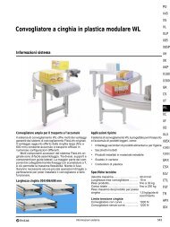
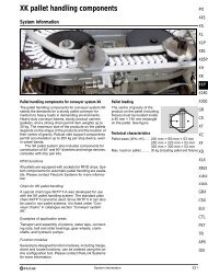
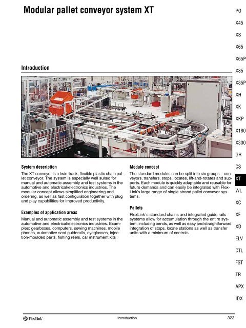
System description<br />
The <strong>XT</strong> <strong>conveyor</strong> is a twin-track, flexible plastic chain <strong>pallet</strong><br />
<strong>conveyor</strong>. The <strong>system</strong> is especially well suited for<br />
manual and automatic assembly and test <strong>system</strong>s in the<br />
automotive and electrical/electronics industries. The<br />
modular concept allows simplified engineering and<br />
ordering, as well as fast configuration together with plug<br />
and play capabilities for improved productivity.<br />
Examples of application areas<br />
Manual and automatic assembly and test <strong>system</strong>s in the<br />
automotive and electrical/electronics industries. Examples:<br />
gearboxes, computers, sewing machines, mobile<br />
phones, automotive seat guiderails, eyeglasses, injection-moulded<br />
parts, fishing reels, car instrument kits<br />
Module concept<br />
The standard modules can be split into six groups – <strong>conveyor</strong>s,<br />
transfers, stops, locates, lift-and-rotates and supports.<br />
Each module is quickly adaptable and reusable for<br />
future demands and can easily be integrated with Flex-<br />
Link’s large range of single strand <strong>pallet</strong> <strong>conveyor</strong> <strong>system</strong>s.<br />
Pallets<br />
<strong>FlexLink</strong>´s standard chains and integrated guide rails<br />
<strong>system</strong>s allow for accumulation through the entire <strong>system</strong>,<br />
including bends, as well as easy and straightforward<br />
integration of stops, locate stations as well as transfer<br />
units with a minimum of controls.<br />
Introduction 323<br />
PO<br />
X45<br />
XS<br />
X65<br />
X65P<br />
X85<br />
X85P<br />
XH<br />
XK<br />
XKP<br />
X180<br />
X300<br />
GR<br />
CS<br />
<strong>XT</strong><br />
WL<br />
XC<br />
XF<br />
XD<br />
ELV<br />
CTL<br />
FST<br />
TR<br />
APX<br />
IDX
Introduction (continued)<br />
System data<br />
25 m maximum <strong>conveyor</strong> length<br />
20 m/min maximum <strong>conveyor</strong> speed<br />
Standard <strong>pallet</strong> sizes from 240×240 mm up to<br />
640×640 mm, including rectangular sizes<br />
30 kg maximum <strong>pallet</strong> weight (8 kg <strong>pallet</strong><br />
weight/100 mm <strong>conveyor</strong><br />
250 kg maximum accumulated weight at 5 m/min.<br />
Maximum permitted load per link 0,5 Kg (<strong>XT</strong>-Compact)<br />
Maximum permitted load per link 1,0 Kg<br />
The modular concept<br />
Introduction<br />
The modular concept includes six groups of modules that<br />
have been defined to suit the various industrial demands.<br />
Most of the <strong>conveyor</strong> modules can be connected back<br />
to back by a connecting kit to form the desired <strong>conveyor</strong><br />
layout. Other modules such as the transfer module or the<br />
locating function module can be incorporated as<br />
required.<br />
The module groups are:<br />
Conveyor modules<br />
Support modules<br />
Transfer modules<br />
Stop function module<br />
Locating function modules<br />
Lift-and-rotate modules<br />
Each module is explained in more detail later on in this<br />
section of the catalogue.<br />
Accessories and spare parts<br />
Accessories and spare parts for the <strong>XT</strong> modules can also<br />
be ordered. Those products are listed after the module<br />
descriptions. See page 345 to 371.<br />
Ordering process<br />
Every <strong>XT</strong> module has its own unique order code which<br />
can be found in each module description. The various<br />
options available for each module are shown in the order<br />
code and all the parameters have to be specified when<br />
ordering.<br />
It is important to know that by ordering for example a<br />
<strong>conveyor</strong> module, you do not automatically get a support<br />
module. This has to be ordered separately.<br />
Product configurator<br />
The easiest way to order <strong>XT</strong> modules is by using the<br />
online product configurator.<br />
324 The modular concept<br />
Typical noise levels<br />
During normal conditions a noise level below 65 dB(A)<br />
can be obtained in an <strong>XT</strong> <strong>conveyor</strong> <strong>system</strong>, including<br />
transfers, stops, etc. However, be aware that the pneumatic<br />
components (valves, etc.) very much affect the<br />
noise level if they are not enclosed correctly. Also, throttle<br />
valves must be adjusted correctly at transfers, stops, etc.<br />
The following table shows typical noise levels.<br />
Speed m/min. 5 10 15 20 30*<br />
dB(A) 56 58 61 65 70<br />
*No standard speed<br />
You can find this webbased configurator at the Flex-<br />
Link website http://www.flexlink.com.<br />
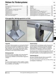
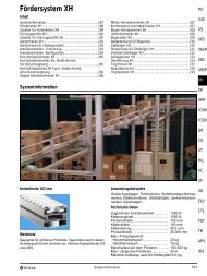
Shipment<br />
Modules are normally delivered in flat boxes with a maximum<br />
length of approximately 3 m. See photo below.<br />
Conveyor modules will be delivered in sections of maximum<br />
3 m which are easy to reassemble. More detailed<br />
information regarding each module is provided in the<br />
section describing the modules. An assembly manual is<br />
available describing how to assemble and connect the<br />
modules. Maintenance and spare parts manuals are also<br />
available.
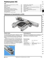
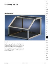
System overview<br />
Typical <strong>XT</strong> <strong>conveyor</strong> layout<br />
The figure below shows a typical <strong>conveyor</strong> layout, built by<br />
connecting various <strong>XT</strong> modules. Note that support modules<br />
are not shown in this overview. For each <strong>conveyor</strong>and<br />
transfer module, a support module has to be ordered<br />
separately, see page 335, “<strong>XT</strong> support modules”.<br />
<strong>XT</strong>UC S11 A<br />
<strong>XT</strong>UL P11 A<br />
<strong>XT</strong>UT M11 A (2×)<br />
<strong>XT</strong>UL P11 A<br />
<strong>XT</strong>UC F51<br />
<strong>XT</strong>UL P11 A<br />
<strong>XT</strong>UT R12 A<br />
<strong>XT</strong>UC L51<br />
<strong>XT</strong>UT R11 A (2×)<br />
Pallet flow in a highway<br />
Characteristic for a highway is a continuous circulation of<br />
<strong>pallet</strong>s, waiting for calling from a transfer operation into a<br />
parallel flow, for instance a workstation. In order to minimize<br />
the noise level and not disturbing the <strong>pallet</strong> more<br />
than necessary in a highway, the <strong>FlexLink</strong> philosophy is<br />
that by default most stop functions attached to a highway<br />
are not activated. The stop function will only be activated<br />
if a <strong>pallet</strong> has to be transferred out from or into the highway.<br />
Workstation<br />
Workstation<br />
<strong>XT</strong>UC J51<br />
<strong>XT</strong>US P11<br />
Highway<br />
Serial<br />
workstation<br />
The figure to the left shows a<br />
modular breakdown of the <strong>XT</strong><br />
layout shown above.<br />
System overview 325<br />
PO<br />
X45<br />
XS<br />
X65<br />
X65P<br />
X85<br />
X85P<br />
XH<br />
XK<br />
XKP<br />
X180<br />
X300<br />
GR<br />
CS<br />
<strong>XT</strong><br />
WL<br />
XC<br />
XF<br />
XD<br />
ELV<br />
CTL<br />
Exception<br />
FST<br />
A Stop function module or a Locating function module<br />
attached directly to a highway will be seen as a serial<br />
workstation and the stop function of these are therefore TR<br />
always activated by default, i.e. all single <strong>pallet</strong>s will be<br />
stopped. This philosophy applies to all <strong>XT</strong> standard mod-<br />
APX<br />
ules.<br />
IDX
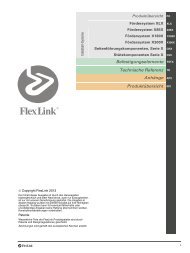
System overview (continued)<br />
Available <strong>XT</strong> modules<br />
Below is an overview of the various modules presented.<br />
The <strong>conveyor</strong> modules can be connected back to back to<br />
form the desired <strong>conveyor</strong> layout. Transfer and locating<br />
modules can be incorporated as required.<br />
326 System overview<br />
For more information about the modules, please see the<br />
detailed information under each module section later on<br />
in this document.<br />
<strong>XT</strong>UC S11 <strong>XT</strong>UC S51 <strong>XT</strong>UC J51/J52 <strong>XT</strong>UC L51/L52<br />
<strong>XT</strong>UC Q51/Q52 <strong>XT</strong>UC U51/U52 <strong>XT</strong>UC Z51/Z52 <strong>XT</strong>UC F51/F52<br />
<strong>XT</strong>UF S01A/S02A/S03A/S04 <strong>XT</strong>UT S10 A/S11 A/S12 A <strong>XT</strong>UT R11 A/R12 A <strong>XT</strong>UT M11 A/M12 A<br />
<strong>XT</strong>US P11 <strong>XT</strong>UL P11 A <strong>XT</strong>UL P12 <strong>XT</strong>UR P11
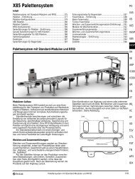
Definition of parameters<br />
Pallet width (PW) × <strong>pallet</strong> length (PL)<br />
Pallet width and <strong>pallet</strong> length. PL is basically the <strong>pallet</strong><br />
dimension in the direction of <strong>pallet</strong> movement in the main<br />
flow. In some modules the <strong>pallet</strong> moves “sideways”, for<br />
example when transferred from one line to another. See<br />
the module descriptions for PL/PW definitions in each<br />
specific case. The figure below shows an example.<br />
320<br />
240<br />
<strong>XT</strong>UL P12 240×320 ...<br />
<strong>XT</strong>UL P12 320×240 ...<br />
<strong>XT</strong>UT S10 240×320 ...<br />
Length (L1, L2 and L3)<br />
The length of each <strong>conveyor</strong> section as defined by each<br />
module drawing.<br />
Length (A)<br />
Length A is the distance between the two inner beams<br />
(outer edges).<br />
Height (H1)<br />
H1 is equivalent to the chain height.<br />
Height (H2)<br />
H2 is equivalent to the chain height of a second, lower,<br />
<strong>conveyor</strong>, if applicable.<br />
Standard/Conductive (AS)<br />
Standard version (AS0)<br />
Conductive version (AS2). See “Static electricity” on<br />
page 331.<br />
Dissipative version (AS3). Only for <strong>XT</strong> Compact.<br />
Slide rail configuration<br />
The following figures show the four different slide rail<br />
options applicable to <strong>XT</strong> <strong>conveyor</strong>s.<br />
G0: No <strong>pallet</strong> side guides<br />
G2: Pallet side guides<br />
G4: No <strong>pallet</strong> side guides, protection of return chain<br />
G6: Pallet side guides, protection of return chain<br />
Motor speed (V)<br />
Equivalent to <strong>conveyor</strong> chain speed in m/min.<br />
Definition of parameters 327<br />
PO<br />
X45<br />
XS<br />
X65<br />
X65P<br />
X85<br />
X85P<br />
XH<br />
XK<br />
XKP<br />
X180<br />
X300<br />
GR<br />
CS<br />
<strong>XT</strong><br />
WL<br />
XC<br />
XF<br />
XD<br />
ELV<br />
CTL<br />
FST<br />
TR<br />
APX<br />
IDX
Definition of parameters (continued)<br />
Motor type (MT)<br />
The motor unit can be mounted on the:<br />
Left side of the <strong>conveyor</strong><br />
Right side of the <strong>conveyor</strong><br />
Below the <strong>conveyor</strong> (mid-mounted)<br />
Left/Right refers to the location of the motor in relation to<br />
the direction of chain travel. See figure.<br />
Left<br />
European /American motor (Hz)<br />
Operating frequency of the motor:<br />
European, 50 Hz<br />
American, 60 Hz.<br />
General information<br />
Right<br />
Support modules<br />
Note that the <strong>conveyor</strong>s and transfers are not delivered<br />
with support modules. They must be ordered separately<br />
(see page 335).<br />
Standard or conductive<br />
The <strong>conveyor</strong>s and transfers can be delivered in standard<br />
and conductive versions, see “Ordering information”. See<br />
also “Static electricity” on page 331.<br />
Note on energy consumption<br />
Since friction build-up is maximum in the bends, keep<br />
<strong>conveyor</strong> sections which are separated from the drive<br />
unit by bends as short as possible, to minimize energy<br />
consumption.<br />
Components and accessories<br />
For detailed component information, see page 345– 370.<br />
328 General information<br />
Queue stop (Q)<br />
Queue stop is used for queue accumulation<br />
Queue stop Q01<br />
No queue stop Q00<br />
Pallet damping (D)<br />
This parameter determines if a non-shock absorbing or<br />
shock absorbing stopper is needed.<br />
No damping of <strong>pallet</strong>, max queue 200 kg (D00)<br />
Max damping of <strong>pallet</strong>, max queue 35 kg (D01)<br />
Max damping of <strong>pallet</strong>, max queue 100 kg (D02).<br />
Function (F)<br />
Use of F depends on module. Currently used with<br />
support modules <strong>XT</strong>UF and modules <strong>XT</strong>UL P11 A<br />
and <strong>XT</strong>UL P12.<br />
Electric control (E)<br />
Options: E00–E02<br />
Without sensors<br />
With PNP sensors<br />
With NPN sensors<br />
Currently used with modules <strong>XT</strong>UL P12 and <strong>XT</strong>UR P11.<br />
See module descriptions for details.<br />
Minimum clearance distance<br />
When two <strong>conveyor</strong>s meet end to end, they must be separated<br />
by a minimum clearance distance. See the figure.<br />
The dimensions shown in the product drawings (L1/L”/...)<br />
include this clearance distance.<br />
L1<br />
10<br />
<strong>XT</strong> “standard”<br />
10<br />
L,L<br />
2 3<br />
4,5<br />
10<br />
L 1<br />
<strong>XT</strong> Compact<br />
Maximum load on <strong>conveyor</strong>s<br />
See “Chain tension calculations” software, and “Technical<br />
information” on page 330.<br />
More information<br />
For logic flowchart and pneumatic diagram: see separate<br />
document <strong>XT</strong> logic flowcharts.
General information (continued)<br />
General dimensions<br />
CC/2<br />
22,5<br />
228<br />
(L2)<br />
(Min 180)*<br />
222,7<br />
248<br />
87<br />
22,5<br />
***<br />
**<br />
62+CC<br />
CC/2<br />
CC<br />
(=PW–30)<br />
228<br />
***<br />
CC<br />
(=PW–30)<br />
180<br />
(L1)<br />
(Min 180)*<br />
* Minimum length of <strong>conveyor</strong> beam section.<br />
248<br />
222,7<br />
248 87 87 248<br />
222,7<br />
13<br />
13<br />
222,7<br />
Note<br />
Attachment of a support module normally requires more<br />
space in this section than 180 mm.<br />
Near a drive unit** or idler end unit** (Fig. A), or a wheel<br />
bend*** (Fig. B), the T-slots are occupied by connecting<br />
strips.<br />
**<br />
87<br />
87<br />
248<br />
222,7<br />
**<br />
336<br />
398<br />
62+CC<br />
186<br />
B<br />
(L2)<br />
(Min 180)*<br />
CC (=PW–30)<br />
A<br />
(Min 180)*<br />
General information 329<br />
**<br />
296+CC<br />
( L1)<br />
228+(CC/2)<br />
228<br />
***<br />
***<br />
80<br />
70<br />
22,5+(CC/2)<br />
58<br />
296<br />
PO<br />
X45<br />
XS<br />
X65<br />
X65P<br />
X85<br />
X85P<br />
XH<br />
XK<br />
XKP<br />
X180<br />
X300<br />
GR<br />
CS<br />
<strong>XT</strong><br />
WL<br />
XC<br />
XF<br />
XD<br />
ELV<br />
CTL<br />
FST<br />
TR<br />
APX<br />
IDX
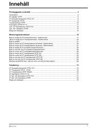
Technical information<br />
Chain tension calculations<br />
Chain tension limit, <strong>XT</strong> <strong>conveyor</strong><br />
See diagrams 1 and 2. See also chain tension calculation<br />
software.<br />
(AS0 = standard chain; AS1 = ISD chain; AS2 = conductive<br />
chain)<br />
N<br />
1800<br />
1600<br />
1400<br />
1200<br />
1000<br />
Tension<br />
800<br />
0 5 10 15 20 25 m<br />
Motor Type H+AS0<br />
Motor Type H+AS2<br />
Standard motor +<br />
AS0, AS2<br />
Conveyor length<br />
Diagram 1. Maximum chain tension vs. <strong>conveyor</strong> length<br />
N<br />
1800<br />
1600<br />
1400<br />
1200<br />
1000<br />
800<br />
Tension<br />
0 5 10 15 20 m/min<br />
Motor Type H+AS0<br />
Motor Type H+AS2<br />
Standard motor +<br />
AS0, AS2<br />
Conveyor speed<br />
Diagram 2. Maximum chain tension vs. <strong>conveyor</strong> speed<br />
Chain tension limit, <strong>XT</strong> Compact <strong>conveyor</strong><br />
Use chain calculation software.<br />
50 Hz motor<br />
Speed (m/min) V05 V10 V15 V20<br />
Fmax (N) 360 350 220 190<br />
60 Hz motor<br />
Speed (m/min) V06 V12 V18<br />
Fmax (N) 360 280 170<br />
330 Technical information<br />
Chain tension limit per track<br />
<strong>XT</strong> <strong>conveyor</strong><br />
Chain type AS0 AS1 AS2<br />
Fmax (N) 900 450 750<br />
<strong>XT</strong> Compact <strong>conveyor</strong><br />
Chain type AS0 AS1 AS2<br />
Fmax (N) 180 180 180<br />
(AS0 = standard chain; AS1 = ISD chain; AS2 = conductive<br />
chain)<br />
Technical data<br />
Drive units<br />
Track 2<br />
Track 1<br />
Drive unit Maximum traction force, N<br />
End drive unit 1250<br />
End drive unit, Type H 1800<br />
Catenary drive unit 1250<br />
Chains, general specifications<br />
Parameter <strong>XT</strong> <strong>XT</strong> Compact<br />
Weight (plain chain) kg/m 0,62 0,28<br />
Tensile strength at 20 °C 900<br />
450 (ISD)<br />
750 (conductive)<br />
Hardness HRB 120 120<br />
Water absorption after 24 hat<br />
20 °C<br />
0,2 % 0,2 %<br />
Chain strength and expansion vs. temperature<br />
180<br />
180 (ISD)<br />
180 (conductive)<br />
Temperature °C –20 0 20 40 60 80 100 120<br />
Tensile strength factor 1,2 1,1 1,0 0,9 0,8 0,6 0,5 0,3<br />
Linear expansion % –0,4 –0,2 0 0,2 0,5 0,8 1,0 1,3<br />
Friction between chain and slide rail<br />
<strong>XT</strong>CR 25 U/ <strong>XT</strong>CR 3 UB<br />
(UHMW-PE, white)....................................... 0,15–0,3<br />
The coefficient of friction is normally the lower value at<br />
the startup of a new <strong>conveyor</strong>. It will increase as the contact<br />
surfaces wear in. Lubrication will reduce the coefficient<br />
of friction.
Technical information (continued)<br />
Friction between chain and <strong>pallet</strong><br />
In most cases, the coefficient of friction for contact<br />
between plain chain and <strong>pallet</strong> is between 0,1 and 0,35.<br />
Temperature limits<br />
A <strong>conveyor</strong> can operate continuously at environment<br />
temperatures from –20 °C to +60 °C. Temperatures up to<br />
+100 °C can be tolerated for short periods (cleaning,<br />
rinsing).<br />
Maximum <strong>conveyor</strong> length<br />
The maximum length of a <strong>conveyor</strong> depends on the tension<br />
in the chain, the speed, and the capacity of the drive<br />
unit.<br />
It is important to calculate and compare the maximum<br />
chain tension and the capacity of the drive unit in the following<br />
situations:<br />
Heavy load<br />
Accumulation<br />
High speed<br />
Long <strong>conveyor</strong><br />
Frequent starts and stops (high service factor).<br />
Static electricity<br />
The standard plastic materials used for <strong>conveyor</strong>s all<br />
have low electrical conductivity. This means that static<br />
electricity can build up on the <strong>conveyor</strong>. If the chain runs<br />
on plastic slide rails, no inherent discharge path exists for<br />
the static electricity.<br />
When a <strong>conveyor</strong> is running under normal operating<br />
conditions but without <strong>pallet</strong>s, the following static build-up<br />
can be measured:<br />
At the drive unit .................................. 2000–2500 V<br />
At the idler end unit ............................ 400–500 V<br />
At a wheel bend ................................. 400–500 V<br />
At a straight section............................ 300–400 V<br />
A <strong>pallet</strong> running on the <strong>conveyor</strong> can also build up static<br />
electricity. The worst case is with accumulated <strong>pallet</strong>s.<br />
Discharge is normally taking place when the <strong>pallet</strong>s are<br />
transferred to or from the <strong>conveyor</strong>. In static sensitive<br />
applications, a number of measures can be taken to<br />
reduce the risk of excessive static charges.<br />
1 Ensure that the relative humidity is minimum 40%.<br />
2 Install static discharge wipers immediately before<br />
sensitive points on the <strong>conveyor</strong>.<br />
Components for static sensitive environments<br />
Some <strong>FlexLink</strong>´s chains and slide rails can be ordered in<br />
carbon loaded versions. The carbon loaded material has<br />
high conductivity.<br />
Contact your <strong>FlexLink</strong> Systems representative for<br />
additional information.<br />
Technical information 331<br />
PO<br />
X45<br />
XS<br />
X65<br />
X65P<br />
X85<br />
X85P<br />
XH<br />
XK<br />
XKP<br />
X180<br />
X300<br />
GR<br />
CS<br />
<strong>XT</strong><br />
WL<br />
XC<br />
XF<br />
XD<br />
ELV<br />
CTL<br />
FST<br />
TR<br />
APX<br />
IDX
<strong>XT</strong> Compact <strong>conveyor</strong> module<br />
Conveyor module S11 Compact<br />
Straight <strong>conveyor</strong>, Compact<br />
PL<br />
PW<br />
L =(L1–9)±3<br />
C<br />
240 ≤ L1 ≤ 3020<br />
c-c:<br />
PW–30<br />
Straight <strong>conveyor</strong> module, Compact <strong>XT</strong>UC S11 ...<br />
<strong>XT</strong> Compact products use standard 1-phase motors,<br />
240 V50Hzor115V60 Hz. For use as stand-alone<br />
unit, as perpendicular link between two <strong>XT</strong> <strong>conveyor</strong><br />
modules, or in-line with another <strong>conveyor</strong> module.<br />
Reversible operation is possible. The module is delivered<br />
fully assembled.<br />
Configuration: see page 334.<br />
The Compact series modules use a different type of<br />
<strong>conveyor</strong> beam and chain as compared to other modules.<br />
Type <strong>XT</strong>UC S11 ... is the only stand-alone Compact<br />
<strong>conveyor</strong> module, but Compact <strong>conveyor</strong>s are<br />
used in Transfer modules.<br />
<strong>XT</strong> <strong>conveyor</strong> modules<br />
Conveyor module S51<br />
Straight <strong>conveyor</strong><br />
c-c:<br />
PW PW–30<br />
PL<br />
860 ≤ L1 ≤ 25 000<br />
Straight <strong>conveyor</strong> module <strong>XT</strong>UC S51 ...<br />
For use as a stand alone unit, in-line with or perpendicular<br />
to another module. Reversible operation is not possible.<br />
Configuration: see page 334.<br />
332 <strong>XT</strong> Compact <strong>conveyor</strong> module<br />
<strong>XT</strong> <strong>conveyor</strong> modules (continued)<br />
Conveyor module J51/J52<br />
Conveyor J<br />
c-c:<br />
PW–30<br />
L1<br />
PL<br />
PW<br />
L2 L2<br />
PL<br />
PW<br />
c-c:<br />
PW–30<br />
(L1+L2) ≤ 25 000<br />
L1, L2 ≥ (1456+PW)/2<br />
<strong>XT</strong>UC J51 <strong>XT</strong>UC J52<br />
Conveyor module type J51<br />
Conveyor module type J52<br />
<strong>XT</strong>UC J51 ...<br />
<strong>XT</strong>UC J52 ...<br />
For use as a stand alone unit, in-line with or perpendicular<br />
to another module. Reversible operation is not possible.<br />
Configuration: see page 334.<br />
Conveyor module L51/L52<br />
Conveyor L<br />
c-c;<br />
PW–30<br />
PL<br />
PW<br />
L2 L2<br />
PL<br />
PW<br />
L1<br />
(L1+L2) ≤ 25 000<br />
L1, L2 ≥ (1456+PW)/2<br />
L1<br />
<strong>XT</strong>UC L51 <strong>XT</strong>UC L52<br />
Conveyor module type L51<br />
Conveyor module type L52<br />
<strong>XT</strong>UC L51 ...<br />
<strong>XT</strong>UC L52 ...<br />
L1<br />
c-c;<br />
PW–30<br />
For use as a stand alone unit, in-line with or perpendicular<br />
to another module. Reversible operation is not possible.<br />
Configuration: see page 334.
<strong>XT</strong> <strong>conveyor</strong> modules (continued)<br />
Conveyor module Q51/Q52<br />
Conveyor Q<br />
L1<br />
c-c:<br />
PW–30<br />
c-c:<br />
PW–30<br />
PW<br />
PL<br />
L2<br />
(1456+PW)/2 ≤ L1 ≤ L2 – (1456+PW)/2<br />
1456+PW ≤ L2 ≤ 6000<br />
L1<br />
PW<br />
PL<br />
L2<br />
Conveyor module type Q51<br />
Conveyor module type Q52<br />
<strong>XT</strong>UC Q51<br />
<strong>XT</strong>UC Q52<br />
<strong>XT</strong>UC Q51 ...<br />
<strong>XT</strong>UC Q52 ...<br />
This type of module uses a catenary drive unit, which<br />
means that the chain runs on the top side only.<br />
For use as a stand alone unit or as a transfer module to<br />
another module. Reversible operation is not possible.<br />
Configuration: see page 334.<br />
Conveyor module U51/U52<br />
Conveyor U<br />
L1, L3 ≥ (1456+PW)/2<br />
c-c: PW–30 c-c: PW–30<br />
L1<br />
L2<br />
PL<br />
PW<br />
L3 L3<br />
L1+L2+L3 ≤ 25 000<br />
PL
Conveyor module configuration examples<br />
Parameter Pallet<br />
width ×<br />
Pallet<br />
length<br />
(mm)<br />
Options 240×240<br />
240×320<br />
320×240<br />
320×320<br />
320×400<br />
400×320<br />
400x400<br />
400×480<br />
400×640<br />
480×400<br />
480×480<br />
480×640<br />
640×480<br />
640×640<br />
Lengths<br />
(mm)<br />
Standard/<br />
Conductive/<br />
Dissipative<br />
Slide rail configuration<br />
334 Conveyor module configuration examples<br />
Motor speed (m/min) Motor type 50 Hz/60<br />
Hz motor<br />
PW×PL L1-L2-L3 AS G V MT Hz<br />
Dimension<br />
ranges:see<br />
module<br />
drawings<br />
AS0 Standard version<br />
AS2 Conductive version<br />
AS3 Dissipative version<br />
G0<br />
G2<br />
G4<br />
G6<br />
V00**<br />
* V20 not available for MT=HM<br />
**V00 without drive motor and torque arm<br />
V05<br />
V10<br />
50 Hz 60 Hz<br />
V15<br />
V20*<br />
V06<br />
V10<br />
V12<br />
V16<br />
V18<br />
V20*<br />
L Left-mounted<br />
<strong>XT</strong>UC S11 PW L1 AS G V MT Hz<br />
<strong>XT</strong>UC S11 240 1834 AS<br />
G2 --- V1<br />
--- --- --- --- M --- E1<br />
0<br />
0<br />
<strong>XT</strong>UC S51 PW L1 AS G V MT Hz<br />
<strong>XT</strong>UC S51 240 12350 AS --- G0 V0 --- --- L A1<br />
2<br />
6<br />
<strong>XT</strong>UC<br />
J51/J52<br />
<strong>XT</strong>UC<br />
L51/L52<br />
PW×PL L1- L2 AS G V MT Hz<br />
<strong>XT</strong>UC J51 240×240 2350-4750 AS<br />
2<br />
--- G4 V1<br />
0<br />
--- --- H<br />
M<br />
A1<br />
<strong>XT</strong>UC<br />
Q51/Q52<br />
PW×PL L1-L2 AS G V MT Hz<br />
<strong>XT</strong>UC Q52 400×480 900-3000 AS --- G2 - - V1<br />
--- --- L --- --- E1<br />
0<br />
0<br />
<strong>XT</strong>UC<br />
U51/U52<br />
<strong>XT</strong>UC<br />
Z51/Z52<br />
<strong>XT</strong>UC<br />
F51/F52<br />
PW×PL L1-L2-L3 AS G V MT Hz<br />
<strong>XT</strong>UC U51 240×320 1200-1350-<br />
1550<br />
AS<br />
0<br />
--- G2 V0<br />
0<br />
--- --- H<br />
M<br />
E1<br />
Parameters: see page 327.<br />
R Right-mounted<br />
M Mid-mounted<br />
HM Heavy mid-mounted<br />
E1 European (50 Hz)<br />
A1 American (60 Hz)
<strong>XT</strong> support modules<br />
Support modules S01A/S02A/S03A/S04<br />
Support module for single <strong>conveyor</strong> module<br />
103<br />
103<br />
P1=<strong>XT</strong> Compact<br />
PW+43<br />
PW–30<br />
P1=<strong>XT</strong><br />
H1 500 ≤ H1 ≤ 1500<br />
PW–51<br />
H1–193<br />
90±35<br />
Support module <strong>XT</strong>UF S01A ...<br />
Including beam support brackets and floor attachment<br />
brackets XCFA 170 S.<br />
Support module for two parallel <strong>conveyor</strong> modules<br />
H1<br />
103<br />
103<br />
P1=<strong>XT</strong> Compact P2=<strong>XT</strong> Compact<br />
45 ≤ A ≤ 2958–2×PW<br />
A<br />
PW+43 PW+43<br />
PW–30 PW–30<br />
P1=<strong>XT</strong> P2=<strong>XT</strong><br />
500 ≤ H1 ≤ 1500<br />
2×PW+A–36<br />
44<br />
H1–193<br />
90±35<br />
Support module <strong>XT</strong>UF S02A ...<br />
Including beam support brackets and floor attachment<br />
brackets XCFA 170 S.<br />
44<br />
Support module for <strong>conveyor</strong> modules at two levels<br />
H1<br />
103<br />
103<br />
H2<br />
P1=<strong>XT</strong> Compact<br />
PW+146<br />
PW+43<br />
PW–30<br />
P1=<strong>XT</strong><br />
PW+15<br />
PW–30<br />
P2=<strong>XT</strong><br />
PW+58<br />
532 ≤ H1 ≤ 1500<br />
332 ≤ H2 ≤ H1–200<br />
H1–193<br />
90±35<br />
Support module <strong>XT</strong>UF S03A ...<br />
Including beam support brackets and floor attachment<br />
brackets XCFA 170 S.<br />
Support module for wheel bends<br />
H1<br />
162<br />
500 ≤ H1 ≤ 1500<br />
H1–252<br />
90±35<br />
Support module <strong>XT</strong>UF S04 ...<br />
Including beam support brackets and floor attachment<br />
brackets XCFA 170 S.<br />
<strong>XT</strong> support modules 335<br />
44<br />
PO<br />
X45<br />
XS<br />
X65<br />
X65P<br />
X85<br />
X85P<br />
XH<br />
XK<br />
XKP<br />
X180<br />
X300<br />
GR<br />
CS<br />
<strong>XT</strong><br />
WL<br />
XC<br />
XF<br />
XD<br />
ELV<br />
CTL<br />
Note.<br />
FST<br />
Two types of beam support brackets are used in the modules:<br />
type 5052899 for standard <strong>XT</strong>, and type 5052621<br />
for <strong>XT</strong> Compact. The brackets are also available sepa- TR<br />
rately. See page 357.<br />
APX<br />
IDX
<strong>XT</strong> support modules (continued)<br />
Distance A<br />
If two parallel <strong>conveyor</strong> modules are joined by a wheel<br />
bend, the distance between <strong>conveyor</strong>s is fixed. In this<br />
case “distance A” in the designation code is always<br />
251 mm. See figure.<br />
251<br />
Distance A in a wheel<br />
bend is always 251 mm<br />
Delivery<br />
The modules will be delivered fully assembled including<br />
beam support brackets and feet, and the screws and nuts<br />
required for connecting to an <strong>XT</strong> or <strong>XT</strong> Compact <strong>conveyor</strong>.<br />
Fasteners for connecting the support modules to<br />
the floor are not included. See also page 324, “The modular<br />
concept/Shipment”.<br />
Application usage<br />
Recommended distance between two support modules<br />
is maximum 2 m.<br />
<strong>XT</strong><br />
103 103<br />
<strong>XT</strong> Compact<br />
Support module configuration examples<br />
Parameter Pallet width<br />
(mm)<br />
Options 240<br />
320<br />
400<br />
480<br />
640<br />
Distance<br />
(mm)<br />
Height 1<br />
(mm)<br />
Height 2<br />
(mm)<br />
336 Support module configuration examples<br />
Ordering information<br />
See configuration examples below. The parameter F is<br />
used to ensure that the support module is delivered with<br />
the correct beam support brackets. It indicates the type of<br />
<strong>XT</strong> <strong>conveyor</strong> supported by the module (<strong>XT</strong> or <strong>XT</strong> Compact,<br />
or a combination of both).<br />
Bracket type (F)<br />
(Definitions of P1 and P2: see figures on page 335.)<br />
Type <strong>XT</strong>UF... F P1 P2<br />
S01A 01 <strong>XT</strong> –<br />
02 <strong>XT</strong> Compact –<br />
S02A 01 <strong>XT</strong> <strong>XT</strong><br />
02 <strong>XT</strong> Compact <strong>XT</strong> Compact<br />
03 <strong>XT</strong> <strong>XT</strong> Compact<br />
S03A 01 <strong>XT</strong> <strong>XT</strong><br />
02 <strong>XT</strong> Compact <strong>XT</strong> Compact<br />
03 <strong>XT</strong> <strong>XT</strong> Compact<br />
04 <strong>XT</strong> Compact <strong>XT</strong><br />
Bracket type<br />
PW A H1 H2 F<br />
Dimension ranges: see module drawings. Parameter<br />
descriptions, see<br />
table above<br />
<strong>XT</strong>UF S01 A PW H1 F<br />
<strong>XT</strong>UF S01 A 240 --- 1225 --- 01 --- ---<br />
<strong>XT</strong>UF S02 A PW A H1 F<br />
<strong>XT</strong>UF S02 A 240 95 1375 --- 02 ---<br />
<strong>XT</strong>UF S03 A PW H1 H2 F<br />
<strong>XT</strong>UF S03 A 240 --- 850 550 02<br />
<strong>XT</strong>UF S04 H1<br />
<strong>XT</strong>UF S04 --- --- 1250 --- --- --- --- ---<br />
Parameters: see page 327.<br />
F01<br />
F02<br />
F03<br />
F04
<strong>XT</strong> transfer modules<br />
Transfer module S10 A<br />
Transfer moduleS–maintocross<br />
D = D00<br />
PW<br />
PW<br />
PL<br />
D = D01<br />
PL<br />
Transfer module S10 <strong>XT</strong>UT S10 A ...<br />
For transfer of <strong>pallet</strong>s/products away from a <strong>conveyor</strong>.<br />
Maximum lifting payload: 30 kg at 6 bar.<br />
Configuration: see page 340.<br />
Transfer module S11 A<br />
Transfer module S – cross to end main<br />
PW<br />
PW<br />
D = D00<br />
PL<br />
D = D01<br />
PL<br />
Transfer module S11 <strong>XT</strong>UT S11 A ...<br />
For receiving of <strong>pallet</strong>s/products to a <strong>conveyor</strong> without<br />
oncoming traffic.<br />
Maximum lifting payload: 30 kg at 6 bar.<br />
Configuration: see page 340.<br />
Transfer module S12 A<br />
Transfer module S – cross to mid main<br />
PW<br />
PW<br />
D = D00<br />
PL<br />
D = D01<br />
PL<br />
Transfer module S12 <strong>XT</strong>UT S12 A ...<br />
For receiving of <strong>pallet</strong>s/products to a <strong>conveyor</strong> with<br />
oncoming traffic.<br />
Maximum lifting payload: 30 kg at 6 bar.<br />
Configuration: see page 340.<br />
Motor<br />
The transfer units are delivered with 15 m/min (E1) or<br />
18 m/min (A1) motor.<br />
Included in the delivery:<br />
One pneumatic transfer unit including the necessary<br />
proximity sensors.<br />
The necessary mounting hardware required for<br />
attachment to an <strong>XT</strong> or <strong>XT</strong> Compact <strong>conveyor</strong>.<br />
The required number of stoppers, dampers and sensor<br />
brackets based on the options selected.<br />
<strong>XT</strong> transfer modules 337<br />
PO<br />
X45<br />
XS<br />
X65<br />
X65P<br />
X85<br />
X85P<br />
XH<br />
XK<br />
XKP<br />
X180<br />
X300<br />
GR<br />
CS<br />
<strong>XT</strong><br />
WL<br />
XC<br />
XF<br />
XD<br />
ELV<br />
CTL<br />
FST<br />
TR<br />
APX<br />
IDX
<strong>XT</strong> transfer modules (continued)<br />
Transfer module R11 A<br />
Transfer module R – cross to end main<br />
D=D01<br />
D=D00<br />
A (45 mm/65* mm)<br />
A (45 mm/65* mm)<br />
338 <strong>XT</strong> transfer modules<br />
PL<br />
PL<br />
PW<br />
*PW 240 mm: A=45 mm<br />
PW<br />
*PW 240 mm: A=45 mm<br />
Transfer module R11 <strong>XT</strong>UT R11 A ...<br />
For transfer of <strong>pallet</strong>s/products from one <strong>conveyor</strong> to a<br />
parallel <strong>conveyor</strong> without oncoming traffic.<br />
Maximum lifting payload: 30 kg at 6 bar.<br />
Configuration: see page 340.<br />
Motor<br />
The transfer units are delivered with 15 m/min (E1) or<br />
18 m/min (A1) motor.<br />
Included in the delivery:<br />
Two pneumatic transfer units including the necessary<br />
proximity sensors.<br />
The necessary mounting hardware required for<br />
attachment to an <strong>XT</strong> or <strong>XT</strong> Compact <strong>conveyor</strong>.<br />
2 roller kits, distance A.<br />
The required number of stoppers, dampers and sensor<br />
brackets based on the options selected.<br />
Transfer module R12 A<br />
Transfer module R – cross to mid main<br />
D=D00<br />
A (45 mm/65* mm)<br />
PL<br />
D=D01 PL<br />
A (45 mm/65* mm)<br />
PW<br />
*PW 240 mm: A=45 mm<br />
*PW 240 mm: A=45 mm<br />
PW<br />
Transfer module R12 <strong>XT</strong>UT R12 A ...<br />
For transfer of <strong>pallet</strong>s/products from one <strong>conveyor</strong> to a<br />
parallel <strong>conveyor</strong> with oncoming traffic.<br />
Maximum lifting payload: 30 kg at 6 bar.<br />
Configuration: see page 340.
<strong>XT</strong> transfer modules (continued)<br />
Transfer module M11 A<br />
Transfer module M – cross to end main<br />
D=D00<br />
240 ≤ L1 ≤ 3020<br />
D=D01<br />
240 ≤ L1 ≤ 3020<br />
PL<br />
Q=Q1<br />
Q=Q1<br />
PL<br />
PW<br />
PW<br />
Transfer module M11 <strong>XT</strong>UT M11 A ...<br />
For transfer of <strong>pallet</strong>s/products from the main <strong>conveyor</strong><br />
to a parallel <strong>conveyor</strong> via an <strong>XT</strong> Compact <strong>conveyor</strong>,<br />
without oncoming traffic.<br />
Maximum lifting payload: 30 kg at 6 bar.<br />
If L1 ≤ 210 + PW it is not possible to use queue stop in<br />
the traverse <strong>conveyor</strong>, i.e. only Q=Q00 is possible<br />
Configuration: see page 340.<br />
Motor<br />
The transfer units are delivered with 15 m/min (E1) or<br />
18 m/min (A1) motor<br />
Included in the delivery:<br />
Two pneumatic transfer units including the necessary<br />
proximity sensors.<br />
One <strong>XT</strong> Compact <strong>conveyor</strong>, length L1, with mounting<br />
brackets.<br />
The necessary mounting hardware required for<br />
attachment to an <strong>XT</strong> or <strong>XT</strong> Compact <strong>conveyor</strong>.<br />
The required number of stoppers, dampers and sensor<br />
brackets based on the options selected.<br />
Transfer module M12 A<br />
Transfer module M – cross to mid main<br />
D=D00<br />
240 ≤ L1 ≤ 3020<br />
D=D01<br />
240 ≤ L1 ≤ 3020<br />
Q=Q1<br />
Q=Q1<br />
<strong>XT</strong> transfer modules 339<br />
PO<br />
X45<br />
XS<br />
X65<br />
X65P<br />
X85<br />
X85P<br />
XH<br />
XK<br />
XKP<br />
X180<br />
X300<br />
GR<br />
Transfer module M12 <strong>XT</strong>UT M12 A ...<br />
CS<br />
For transfer of <strong>pallet</strong>s/products from one <strong>conveyor</strong> to a<br />
parallel <strong>conveyor</strong>, via an <strong>XT</strong> Compact <strong>conveyor</strong>, with<br />
oncoming traffic.<br />
<strong>XT</strong><br />
Maximum lifting payload: 30 kg at 6 bar.<br />
If L1 ≤ 210 + PW it is not possible to use queue stop in<br />
the traverse <strong>conveyor</strong>, i.e. only Q=Q00 is possible WL<br />
Configuration: see page 340.<br />
XC<br />
PL<br />
PL<br />
PW<br />
PW<br />
XF<br />
XD<br />
ELV<br />
CTL<br />
FST<br />
TR<br />
APX<br />
IDX
Transfer module configuration examples<br />
Parameter Pallet width ×<br />
Pallet length<br />
(mm)<br />
Lengths<br />
(mm)<br />
Distance (mm)<br />
Standard/<br />
Conductive/<br />
Dissipative<br />
Motor speed (m/min)<br />
PW×PL L1 A AS V MT Hz Q D<br />
Options 240×240 Dimension<br />
*V10 speed <strong>XT</strong> Compact <strong>conveyor</strong><br />
240×320 ranges: see<br />
320×240 module draw-<br />
320×320<br />
320×400<br />
400×320<br />
400x400<br />
400×480<br />
ings<br />
400×640<br />
480×400<br />
480×480<br />
480×640<br />
640×480<br />
640×640<br />
50 Hz 60 Hz<br />
AS0 Standard version<br />
340 Transfer module configuration examples<br />
AS2 Conductive version<br />
V05<br />
V10<br />
V15<br />
<strong>XT</strong>UT S10 A<br />
<strong>XT</strong>UT S11 A<br />
<strong>XT</strong>UT S12 A<br />
PW×PL AS V MT Hz D<br />
<strong>XT</strong>UT S11 A 240×320 --- --- AS0 --- --- V15 --- --- --- M E1 --- --- D00<br />
<strong>XT</strong>UT R11 A<br />
<strong>XT</strong>UT R12 A<br />
PW×PL A AS V MT Hz D<br />
<strong>XT</strong>UT R11 A 240×320 --- 45 AS0 --- --- --- --- --- V18 M A1 --- --- D01<br />
<strong>XT</strong>UT M11 A<br />
<strong>XT</strong>UT M12 A<br />
PW×PL L1 A AS V MT Hz Q D<br />
<strong>XT</strong>UT M11 A 240×320 1350 45 AS0 V10* M E1 Q00 D01<br />
Parameters: see page 327.<br />
V20<br />
V06<br />
V12<br />
V18<br />
Motor type<br />
M Mid-mounted<br />
European/American<br />
motor<br />
E1 European (50 Hz)<br />
A1 American (60 Hz)<br />
Queue stop<br />
traverse <strong>conveyor</strong><br />
Q00 No queue stop<br />
Q01 Queue stop<br />
Pallet damping<br />
D00 No damping<br />
D01 Damping, max queue 35 kg
<strong>XT</strong> function modules<br />
Locating function module P11 A F00<br />
Locating function module (option F00)<br />
D=D00<br />
D=D01<br />
D=D02<br />
Locating function module <strong>XT</strong>UL P11 A ...F00<br />
Singulates to stop and locates one <strong>pallet</strong> at a time along<br />
the <strong>conveyor</strong> with a repeatability in x and y directions of<br />
±0,05 mm.<br />
Two diagonal lift units with guide pins. Only for PW or PL<br />
≤ 400 mm<br />
Configuration: see page 344.<br />
Included in the delivery:<br />
One locating station, including non-return throttle<br />
valves.<br />
The necessary number of stoppers and sensor brackets,<br />
based on the option selected.<br />
The necessary mounting hardware required for<br />
attachment to an <strong>XT</strong> or <strong>XT</strong> Compact <strong>conveyor</strong>.<br />
Locating function module P11 A F01<br />
Locating function module (option F01)<br />
D = D00<br />
D = D01<br />
D = D02<br />
Locating function module <strong>XT</strong>UL P11 A ...F01<br />
Singulates to stop and locates one <strong>pallet</strong> at a time<br />
along the <strong>conveyor</strong> with a repeatability in x and y directions<br />
of ±0,05 mm.<br />
Four lift units: two diagonal lift units with guide pins and<br />
two without guide pins.<br />
Configuration: see page 344.<br />
<strong>XT</strong> function modules 341<br />
PO<br />
X45<br />
XS<br />
X65<br />
X65P<br />
X85<br />
X85P<br />
XH<br />
XK<br />
XKP<br />
X180<br />
X300<br />
GR<br />
CS<br />
<strong>XT</strong><br />
WL<br />
XC<br />
XF<br />
XD<br />
ELV<br />
CTL<br />
FST<br />
TR<br />
APX<br />
IDX
<strong>XT</strong> function modules (continued)<br />
Stop function module P11<br />
Stop function<br />
D = D00<br />
D = D01<br />
D = D02<br />
Stop function <strong>XT</strong>US P11 ...<br />
Singulates and stops one <strong>pallet</strong> at a time along the <strong>conveyor</strong><br />
line with a repeatability of ±1 mm. The stop units<br />
can be mounted on the opposite side of the beam to<br />
facilitate <strong>pallet</strong> stopping at the front end of the <strong>pallet</strong>.<br />
Configuration: see page 344.<br />
Included in the delivery:<br />
The necessary number of stoppers and sensor brackets,<br />
based on the option selected.<br />
The necessary mounting hardware required for<br />
attachment to an <strong>XT</strong> or <strong>XT</strong> Compact <strong>conveyor</strong>.<br />
342 <strong>XT</strong> function modules<br />
Lift-and-locate function module <strong>XT</strong>UL P12<br />
The lift-and-locate function is used when a product needs<br />
to be located at a specific height prior to a machine operation.<br />
The device can be mounted in three ways (options<br />
F00–F02).<br />
PW<br />
PL<br />
A 50<br />
Lift-and-locate module (option F00)<br />
475<br />
132<br />
Locating pin<br />
Height adjustment<br />
PW–95<br />
PL–20<br />
181<br />
46,5<br />
46,5<br />
181<br />
140<br />
125<br />
B<br />
45<br />
115<br />
M8 (4x)<br />
Lift-and-locate function<br />
module <strong>XT</strong>UL P12 ... F00 ...<br />
Option F=00: Module is attached to horizontal surface.<br />
Configuration: see page 344.
<strong>XT</strong> function modules – Lift-and-locate function module <strong>XT</strong>UL P12 (continued)<br />
Lift-and-locate module (option F01)<br />
PW–95<br />
≈ 482<br />
Lift-and-locate function module <strong>XT</strong>UL P12 ... F01 ...<br />
Option F=01: Module is attached to <strong>conveyor</strong>.<br />
Other dimensions: see <strong>XT</strong>UL P12 ... F00 ...<br />
Configuration: see page 344.<br />
Lift-and-locate module (option F02)<br />
PW–95<br />
≈ 482<br />
500 ≤ H1 ≤ 1500<br />
Lift-and-locate function module <strong>XT</strong>UL P12 ... F02 ...<br />
Option F= 02: Module is attached to support frame.<br />
Other dimensions: see <strong>XT</strong>UL P12 ... F00 ...<br />
Configuration: see page 344.<br />
H1<br />
PO<br />
Delivery<br />
One lift-and-locate module, including non-return throt- X45<br />
tle valves.<br />
The necessary number of stoppers and sensor brack- XS<br />
ets, based on the option selected.<br />
The necessary mounting hardware required for X65<br />
attachment to an <strong>XT</strong> or <strong>XT</strong> Compact <strong>conveyor</strong>,<br />
depending on the F01 or F02 option.<br />
X65P<br />
Lift-and-rotate function module <strong>XT</strong>UR P11<br />
The lift-and-rotate module can turn the <strong>pallet</strong> 180°. It can<br />
X85<br />
be useful in <strong>system</strong>s with a mix of bends and transfers, or<br />
in a process where the <strong>pallet</strong> needs to be rotated prior to X85P<br />
a machine operation.<br />
A<br />
B<br />
XH<br />
PW<br />
PL<br />
<strong>XT</strong> function modules 343<br />
110<br />
XK<br />
XKP<br />
X180<br />
X300<br />
Note<br />
GR<br />
To protect persons from the clamp risk, the unit must be<br />
covered .<br />
CS<br />
Delivery<br />
One lift-and-rotate station, including non-return throt- <strong>XT</strong><br />
tle valves<br />
The necessary number of stoppers and sensor brack- WL<br />
ets, based on the options selected<br />
The necessary mounting hardware required for con- XC<br />
nection to an <strong>XT</strong> or <strong>XT</strong> Compact <strong>conveyor</strong>.<br />
XF<br />
XD<br />
ELV<br />
CTL<br />
FST<br />
TR<br />
APX<br />
IDX
<strong>XT</strong> function modules – Lift-and-rotate function module <strong>XT</strong>UR P11 (continued)<br />
Lift-and-rotate function module<br />
PW–75<br />
PW–95<br />
Locating pin<br />
Hydraulic dampers<br />
for end damping<br />
Height adjustment for <strong>XT</strong><br />
and <strong>XT</strong> Compact<br />
344 Function module configuration examples<br />
PL-20<br />
96<br />
* Height adjustability: 14,5 mm<br />
Lift-and-rotate function module <strong>XT</strong>UR P11 ...<br />
Function module configuration examples<br />
Parameter Pallet width ×<br />
Pallet length<br />
(mm)<br />
Options 240×240<br />
240×320<br />
320×240<br />
320×320<br />
320×400<br />
400×320<br />
400x400<br />
*400×480<br />
*400×640<br />
*480×400<br />
*480×480<br />
*480×640<br />
*640×480<br />
*640×640<br />
*Not for <strong>XT</strong>UR P11<br />
Height 1<br />
(mm)<br />
Pallet damping Function Electric control<br />
PW×PL H1 D F E<br />
500 mm< H1
Pallets<br />
Introduction<br />
Ten <strong>pallet</strong> sizes are available:<br />
240 × 240 mm<br />
240 × 320 mm<br />
320 × 320 mm<br />
320 × 400 mm<br />
400 × 400 mm<br />
400 × 480 mm<br />
400 × 640 mm<br />
480 × 480 mm<br />
480 × 640 mm<br />
640 × 640 mm<br />
For non-standard <strong>pallet</strong> dimensions, or for other <strong>pallet</strong><br />
plate materials than steel, frame section kits and bushing<br />
kits can be ordered. See next page.<br />
Note!<br />
Side view<br />
Top view Bottom view<br />
PL/10<br />
PL/2<br />
PL<br />
In order to get a good transition between two <strong>conveyor</strong>s<br />
or in a transfer station, max. displacement of point of<br />
gravity should not exceed ±PL/10.<br />
Pallets 345<br />
PO<br />
X45<br />
XS<br />
X65<br />
X65P<br />
X85<br />
X85P<br />
Technical specifications<br />
XH<br />
Maximum load on the <strong>pallet</strong> is 80 N per 100 mm of<br />
<strong>pallet</strong> length (PL).<br />
XK<br />
Friction between <strong>pallet</strong> and chain, μp = 0,3 (under normal<br />
conditions).<br />
The table below shows maximum <strong>pallet</strong> load for each XKP<br />
<strong>pallet</strong> size.<br />
X180<br />
Size (PW × PL) Pallet weight (kg) Max load on <strong>pallet</strong> (kg)<br />
240 × 240 mm 2,6 17<br />
240 × 320 mm 3,5 22<br />
320 × 240 mm 3,5 16<br />
320 × 320 mm 4,4 22<br />
320 × 400 mm 5,5 24<br />
400 × 320 mm 5,5 20<br />
400 × 400 mm 6,8 23<br />
400 × 480 mm 8,2 22<br />
400 × 640 mm 10,8 19<br />
480 × 400 mm 8,2 22<br />
480 × 480 mm 9,8 20<br />
480 × 640 mm 13,0 17<br />
640 × 400 mm 10,8 19<br />
640 × 480 mm 13,0 17<br />
640 × 640 mm 17,4 13<br />
Material specifications<br />
Pallet plate ..................... 5 mm ±0,1 steel plate<br />
Frame............................. Electrically conductive<br />
UHMW-PE<br />
X300<br />
GR<br />
CS<br />
<strong>XT</strong><br />
WL<br />
XC<br />
XF<br />
XD<br />
ELV<br />
CTL<br />
FST<br />
TR<br />
APX<br />
IDX
Pallets (continued)<br />
Pallet PW×PL<br />
∅12 H7 (4×)<br />
*<br />
∅0,1 M A<br />
PL–75,5<br />
PL–36<br />
0<br />
PL–0,5<br />
PL+10<br />
13,6<br />
39,5<br />
50,7<br />
346 Pallets<br />
18<br />
PW–75,5<br />
18<br />
PW–36<br />
25 10<br />
0<br />
PW–0,5<br />
PW+10<br />
PW×PL 240×240 240×320 320×320 320×400 400×400 400×480 400×640 480×480 480×640 640×640<br />
0,3 0,5 0,5 0,6 0,6 0,8 0,8 0,8 1,0 1,0<br />
Pallet PW × PL mm <strong>XT</strong>PP PW×PL<br />
When ordering, insert the <strong>pallet</strong> width and the <strong>pallet</strong> length instead of PW×PL in the designation.<br />
Frame section kit<br />
Frame section kit 240 mm<br />
Frame section kit 320 mm<br />
Frame section kit 400 mm<br />
Frame section kit 480 mm<br />
Frame section kit 640 mm<br />
5056945<br />
5056950<br />
5056938<br />
5056940<br />
5056952<br />
Each kit contains two frame pieces, six bushings and four initiation plates with screws. The frames and bushings are<br />
suitable for screws type MC6S M6×16 (not included). Two kits are required for each <strong>pallet</strong>.<br />
For use as spare parts and for building non-standard <strong>pallet</strong>s in combination with customer supplied <strong>pallet</strong> plates.<br />
Bushing kit<br />
Four bushings<br />
5056944<br />
For building non-standard <strong>pallet</strong>s in combination with customer supplied <strong>pallet</strong> plates. The bushings are designed for<br />
plate thickness 5 mm and should be press-fitted into ∅16 mm holes.<br />
36<br />
34<br />
12<br />
20<br />
*<br />
5<br />
A
Pallet stop devices<br />
Pallet stop device U200<br />
20<br />
40<br />
20<br />
40<br />
24<br />
M5<br />
M5<br />
50<br />
∅8,2<br />
Pneumatic stopper, 0–200 kg <strong>XT</strong>PD U200<br />
Pressure range: Treated compressed air: 4–8 bar<br />
Air connection: 6 mm outside diameter tubing<br />
Separating function:<br />
Open: pneumatically. Close: spring-loaded.<br />
Mounting hardware is included.<br />
Pallet stop device UR<br />
21<br />
42<br />
21<br />
42<br />
∅6,2<br />
50<br />
∅8,2<br />
50<br />
50<br />
7<br />
25<br />
7<br />
9<br />
9<br />
38,5<br />
39<br />
80<br />
80<br />
60<br />
60<br />
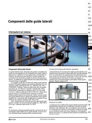
kg<br />
250<br />
200<br />
150<br />
100<br />
50<br />
0<br />
Load<br />
0 5 10 15 20 25 30 m/min<br />
Maximum load vs. <strong>conveyor</strong> speed<br />
Speed<br />
To reduce the noise level, the stopper includes an integrated<br />
throttle valve. The throttle setting can be adjusted<br />
by means of a screwdriver.<br />
The diagram shows the maximum permissible weight of<br />
a group of <strong>pallet</strong>s (product weight + <strong>pallet</strong> weight), which<br />
the stop device is capable of stopping, as a function of<br />
the <strong>conveyor</strong> speed.<br />
Pallet stop devices 347<br />
ST P<br />
Stop <strong>XT</strong>PD UR prevents the <strong>pallet</strong> from sliding<br />
backwards.<br />
Return stop <strong>XT</strong>PD UR The necessary mounting hardware for attachment to an<br />
<strong>XT</strong> or <strong>XT</strong> Compact <strong>conveyor</strong> is included in the delivery.<br />
Used in combination with <strong>pallet</strong> stop devices<br />
<strong>XT</strong>PD U200, D35 or D100.<br />
PO<br />
X45<br />
XS<br />
X65<br />
X65P<br />
X85<br />
X85P<br />
XH<br />
XK<br />
XKP<br />
X180<br />
X300<br />
GR<br />
CS<br />
<strong>XT</strong><br />
WL<br />
XC<br />
XF<br />
XD<br />
ELV<br />
CTL<br />
FST<br />
TR<br />
APX<br />
IDX
Pallet stop devices (continued)<br />
Side support for <strong>pallet</strong> stop<br />
6,5<br />
10<br />
30<br />
15<br />
48 62<br />
74<br />
8<br />
3<br />
Pallet stop<br />
Side support 5055955<br />
The side support is used with <strong>pallet</strong> sizes larger than<br />
400 mm × 400 mm to minimize the transverse force on<br />
the side guide. Hardware for attachment to the <strong>conveyor</strong><br />
is included in the delivery.<br />
Pallet stop device, damped<br />
40<br />
20<br />
40<br />
20<br />
24<br />
76<br />
76<br />
38,7<br />
348 Pallet stop devices<br />
M5<br />
M5<br />
M6<br />
M6<br />
75,5<br />
75,5<br />
18,5<br />
8,2<br />
8,2<br />
18,5<br />
67,7<br />
67,7<br />
Load<br />
kg<br />
50<br />
45<br />
40<br />
35<br />
30<br />
25<br />
0<br />
0 5 10 15 20 25 m/min<br />
Speed<br />
Maximum load vs. <strong>conveyor</strong> speed<br />
Damped stopper, 0–35 kg <strong>XT</strong>PD D35 To reduce the noise level, throttle valves should be used<br />
Pressure range: Treated compressed air: 4–8 bar<br />
Air connection: 6 mm outside diameter tubing<br />
Separating function:<br />
Open: pneumatically. Close: spring-loaded<br />
Mounting hardware is included.<br />
(M5). These are not included. The diagram shows the<br />
maximum permissible weight of a group of <strong>pallet</strong>s (product<br />
weight + <strong>pallet</strong> weight), which the stop device is<br />
capable of stopping, as a function of the <strong>conveyor</strong><br />
speed.
Pallet stop devices (continued)<br />
Pallet stop device, damped<br />
9<br />
22<br />
∅8,2<br />
∅10,2<br />
97<br />
95<br />
80<br />
19 10<br />
39<br />
M5<br />
80<br />
kg<br />
130<br />
120<br />
110<br />
100<br />
80<br />
60<br />
0<br />
0 5 10 15 20 25 30 m/min<br />
Maximum load vs. <strong>conveyor</strong> speed<br />
Damped stopper, 0–100 kg <strong>XT</strong>PD D100 To reduce the noise level, throttle valves should be used<br />
Pressure range: Treated compressed air: 4–8 bar<br />
Air connection: 6 mm outside diameter tubing<br />
Separating function:<br />
Open: pneumatically. Close: spring-loaded<br />
Mounting hardware is included.<br />
Load<br />
Speed<br />
(M5). These are not included. The diagram shows the<br />
maximum permissible weight of a group of <strong>pallet</strong>s (product<br />
weight + <strong>pallet</strong> weight), which the stop device is<br />
capable of stopping, as a function of the <strong>conveyor</strong><br />
speed.<br />
Pallet stop devices 349<br />
PO<br />
X45<br />
XS<br />
X65<br />
X65P<br />
X85<br />
X85P<br />
XH<br />
XK<br />
XKP<br />
X180<br />
X300<br />
GR<br />
CS<br />
<strong>XT</strong><br />
WL<br />
XC<br />
XF<br />
XD<br />
ELV<br />
CTL<br />
FST<br />
TR<br />
APX<br />
IDX
Dampers<br />
Damper, parallel to main<br />
<strong>XT</strong> Compact <strong>conveyor</strong> beam<br />
<strong>XT</strong> <strong>conveyor</strong> beam<br />
19<br />
19<br />
Damper, 0–30 kg <strong>XT</strong>PA CM35<br />
Note<br />
The damper is easily influenced by pressure from other<br />
pneumatic equipment. To avoid this interference the<br />
damper must be connected to a separate pneumatic<br />
valve.<br />
Damper, main to parallel<br />
<strong>XT</strong> Compact <strong>conveyor</strong> beam<br />
L<br />
350 Dampers<br />
74<br />
60<br />
74<br />
60<br />
70<br />
M5<br />
M5<br />
20 40<br />
Damper, 0–30 kg<br />
PW 240 mm, L=136 <strong>XT</strong>PA MC35 240 A<br />
PW 320 mm, L=216 <strong>XT</strong>PA MC35 320 A<br />
PW 400 mm, L=296 <strong>XT</strong>PA MC35 400 A<br />
PW 480 mm, L=376 <strong>XT</strong>PA MC35 480 A<br />
PW 640 mm, L=536 <strong>XT</strong>PA MC35 640 A<br />
Mounting hardware is included in the delivery.<br />
13,5<br />
94<br />
40<br />
60<br />
M5<br />
Load<br />
kg<br />
35<br />
30<br />
25<br />
20<br />
15<br />
10<br />
5<br />
0 5 10 15 20 25 m/min Speed<br />
Maximum load vs. <strong>conveyor</strong> speed<br />
The diagram shows the maximum permissible weight of<br />
a group of <strong>pallet</strong>s (product weight + <strong>pallet</strong> weight), which<br />
the damper is capable of stopping, as a function of the<br />
<strong>conveyor</strong> speed.<br />
The pneumatic damper <strong>XT</strong>PA CM35 is used when <strong>pallet</strong>s<br />
up to 30 kg have to be damped and transferred from<br />
a parallel <strong>conveyor</strong> to the main <strong>conveyor</strong>.<br />
Mounting hardware is included in the delivery.<br />
Pressure range: Treated compressed air, 4–8 bar<br />
Air connection: 6 mm outside diameter tubing<br />
Damping function:<br />
Stop in initial position: pneumatically<br />
Load<br />
kg<br />
35<br />
30<br />
25<br />
20<br />
15<br />
10<br />
5<br />
0 5 10 15 20 25 m/min<br />
Speed<br />
Maximum load vs. <strong>conveyor</strong> speed<br />
The diagram shows the maximum permissible weight of<br />
a group of <strong>pallet</strong>s (product weight + <strong>pallet</strong> weight), which<br />
the damper is capable of stopping, as a function of the<br />
<strong>conveyor</strong> speed.<br />
Pressure range: Treated compressed air, 4–8 bar<br />
Air connection: 6 mm outside diameter tubing<br />
Damping function: Stop in initial position, pneumatically<br />
Note.<br />
The damper is easily influenced by pressure from other<br />
pneumatic equipment. To avoid this interference the<br />
damper must be connected to a separate pneumatic<br />
valve.
Sensor brackets<br />
Sensor bracket Type V001<br />
25<br />
20<br />
39,5<br />
31<br />
∅12<br />
Vertical sensor bracket <strong>XT</strong>PB V001<br />
The sensor bracket holds a ∅12 mm vertical sensor<br />
and can be mounted on the stopper <strong>XT</strong>PD U200 and<br />
the damped stopper <strong>XT</strong>PD D35.<br />
Mounting hardware is included in the delivery.<br />
Proximity switch is not included.<br />
Sensor bracket Type V002<br />
24,5<br />
39<br />
50<br />
40<br />
32<br />
22<br />
Vertical sensor bracket <strong>XT</strong>PB V002<br />
The sensor bracket holds a ∅12 mm vertical sensor<br />
and is mounted on the inside of the beam.<br />
Mounting hardware is included in the delivery.<br />
Proximity switch not included<br />
18<br />
∅12<br />
Sensor bracket Type V003<br />
17<br />
48,5<br />
62<br />
34<br />
96<br />
Sensor brackets 351<br />
85<br />
65<br />
Vertical position sensor bracket <strong>XT</strong>PB V003<br />
The position sensor has an increased range and is<br />
mounted on the outside of the beam of an <strong>XT</strong> or <strong>XT</strong><br />
Compact <strong>conveyor</strong>. It is intended for use with a ∅12 mm<br />
proximity switch.<br />
Mounting hardware is included in the delivery.<br />
Proximity switch is not included.<br />
Sensor bracket Type H001<br />
78 55<br />
40<br />
∅12<br />
40<br />
13<br />
25<br />
Horizontal sensor bracket <strong>XT</strong>PB H001<br />
The sensor bracket holds a ∅12 mm horizontal proximity<br />
switch and is mounted on the outside of the beam of<br />
an <strong>XT</strong> or <strong>XT</strong> Compact <strong>conveyor</strong>.<br />
Mounting hardware is included in the delivery.<br />
Proximity sensor is not included.<br />
The horizontal proximity sensor (∅12 mm) must have a<br />
minimum effective sensing distance of 5 mm to the<br />
steel initiator plate in the <strong>pallet</strong>.<br />
Example: The effective sensing distance for SICK<br />
(IM12 sensing range 8 mm) is 6,48 mm. This is calculated<br />
as follows: 8 mm × 0,81*.<br />
*Useful sensing range = 0,81 × nominal sensing range.<br />
∅6,2<br />
∅8,2<br />
PO<br />
X45<br />
XS<br />
X65<br />
X65P<br />
X85<br />
X85P<br />
XH<br />
XK<br />
XKP<br />
X180<br />
X300<br />
GR<br />
CS<br />
<strong>XT</strong><br />
WL<br />
XC<br />
XF<br />
XD<br />
ELV<br />
CTL<br />
FST<br />
TR<br />
APX<br />
IDX
Pneumatic transfer units<br />
Pneumatic transfer Type M1<br />
14<br />
7 Transfer unit Type 240V50Hz<br />
motor<br />
352<br />
C-C<br />
L<br />
Pneumatic transfer Type M1*<br />
Standard chain, 50 Hz<br />
Standard chain, 60 Hz<br />
Conductive chain, 50 Hz<br />
Conductive chain, 60 Hz<br />
352 Pneumatic transfer units<br />
W<br />
<strong>XT</strong>PT PW×PL-01<br />
<strong>XT</strong>PT PW×PL-02<br />
<strong>XT</strong>PT PW×PL-03<br />
<strong>XT</strong>PT PW×PL-04<br />
When ordering, insert the <strong>pallet</strong> size instead of PW×PL<br />
in the designation.<br />
*For the following <strong>pallet</strong> sizes (PW×PL):<br />
240×240: C-C=210, W=169, L=259<br />
240×320: C-C=290, W=169, L=339<br />
320×240: C-C=210, W=249, L=259<br />
Load<br />
kg<br />
35<br />
30<br />
25<br />
20<br />
15<br />
10<br />
5<br />
No damper<br />
With damper<br />
0 5 10 15 20 25 30 m/min<br />
Maximum load vs. <strong>conveyor</strong> speed<br />
Speed<br />
115V60Hz<br />
motor<br />
<strong>XT</strong>PT 240×240–... M1 S8R25GX-T1 S8R25GE-T1<br />
<strong>XT</strong>PT 240×320–... M1 S8R25GX-T1 S8R25GE-T1<br />
<strong>XT</strong>PT 320×240–... M1 S8R25GX-T1 S8R25GE-T1<br />
Connectors for proximity switches<br />
M8 (2×)<br />
Connector for motor cable<br />
(1-phase)<br />
Pneumatic connections ∅6 mm<br />
(2×)<br />
14<br />
4 2<br />
5 1 3<br />
5/3 valve<br />
Mid position pressurized<br />
12<br />
Throttle valves (2×)<br />
Scope of delivery<br />
Throttle valves (2×)<br />
Motor cable connector<br />
The connector for motor cable is a male 3-pole insert<br />
with a housing for the insert. To connect, a female 3-pole<br />
insert with a hood for the insert and a screw cap for the<br />
hood are required (not supplied by <strong>FlexLink</strong>). Suitable<br />
types are Weidmüller 1498200000 (insert),1788520000<br />
(hood), and 13-08080521 (M20 screw cap), or equivalent.<br />
The diagram shows the maximum permissible weight of<br />
a <strong>pallet</strong> (product weight + <strong>pallet</strong> weight), which the transfer<br />
is capable of stopping, as a function of the <strong>conveyor</strong><br />
speed. This diagram applies to transfers type M1, M2<br />
and L.
Pneumatic transfer units (continued)<br />
Pneumatic transfer Type M2<br />
14<br />
7<br />
237<br />
C-C<br />
L<br />
Pneumatic transfer Type M2*<br />
Standard chain, 50 Hz<br />
Standard chain, 60 Hz<br />
Conductive chain, 50 Hz<br />
Conductive chain, 60 Hz<br />
<strong>XT</strong>PT PW×PL-01<br />
<strong>XT</strong>PT PW×PL-02<br />
<strong>XT</strong>PT PW×PL-03<br />
<strong>XT</strong>PT PW×PL-04<br />
When ordering, insert the <strong>pallet</strong> size instead of PW×PL<br />
in the designation.<br />
*For the following <strong>pallet</strong> sizes (PW×PL):<br />
320×320: C-C=290, W=249, L=339<br />
320×400: C-C=370, W=249, L=419<br />
400×320: C-C=290, W=329, L=339<br />
400×400: C-C=370, W=329, L=419<br />
400×480: C-C=450, W=329, L=499<br />
400×640: C-C=610, W=329, L=659<br />
W<br />
Transfer unit Type 240V50Hz<br />
motor<br />
115V60Hz<br />
motor<br />
<strong>XT</strong>PT 320×320–... M2 S9R40GXH-T S9R40GEH-T<br />
<strong>XT</strong>PT 320×400–... M2 S9R40GXH-T S9R40GEH-T<br />
<strong>XT</strong>PT 400×320–... M2 S9R40GXH-T S9R40GEH-T<br />
<strong>XT</strong>PT 400×400–... M2 S9R40GXH-T S9R40GEH-T<br />
<strong>XT</strong>PT 400×480–... M2 S9R40GXH-T S9R40GEH-T<br />
<strong>XT</strong>PT 400×640–... M2 S9R40GXH-T S9R40GEH-T<br />
Connector for<br />
motor cable<br />
(1-phase)<br />
Connectors for proximity<br />
switches M8 (2×)<br />
14<br />
4 2<br />
5 1 3<br />
5/3 valve<br />
Mid position pressurized<br />
12<br />
Throttle valves (2×)<br />
Pneumatic connections<br />
∅6 mm (2×)<br />
Scope of delivery<br />
Throttle valves (2×)<br />
Motor cable connector<br />
The connector for motor cable is a male 3-pole insert<br />
with a housing for the insert. To connect, a female 3-pole<br />
insert with a hood for the insert and a screw cap for the<br />
hood are required (not supplied by <strong>FlexLink</strong>). Suitable<br />
types are Weidmüller 1498200000 (insert),1788520000<br />
(hood), and 13-08080521 (M20 screw cap), or equivalent.<br />
Pneumatic transfer units 353<br />
PO<br />
X45<br />
XS<br />
X65<br />
X65P<br />
X85<br />
X85P<br />
XH<br />
XK<br />
XKP<br />
X180<br />
X300<br />
GR<br />
CS<br />
<strong>XT</strong><br />
WL<br />
XC<br />
XF<br />
XD<br />
ELV<br />
CTL<br />
FST<br />
TR<br />
APX<br />
IDX
Pneumatic transfer units (continued)<br />
Pneumatic transfer Type L<br />
14<br />
7<br />
277<br />
Pneumatic transfer Type L*<br />
Standard chain, 50 Hz<br />
Standard chain, 60 Hz<br />
Conductive chain, 50 Hz<br />
Conductive chain, 60 Hz<br />
C-C<br />
L<br />
<strong>XT</strong>PT PW×PL-01<br />
<strong>XT</strong>PT PW×PL-02<br />
<strong>XT</strong>PT PW×PL-03<br />
<strong>XT</strong>PT PW×PL-04<br />
When ordering, insert the <strong>pallet</strong> size instead of PW×PL<br />
in the designation.<br />
*For the following <strong>pallet</strong> sizes (PW×PL):<br />
480×400: C-C=370, W=405, L=439<br />
480×480: C-C=450, W=405, L=519<br />
480×640: C-C=610, W=405, L=679<br />
640×400: C-C=370, W=565, L=439<br />
640×480: C-C=450, W=565, L=519<br />
640×640: C-C=610, W=565, L=679<br />
354 Pneumatic transfer units<br />
W<br />
Transfer unit Type 240V50Hz<br />
motor<br />
115V60Hz<br />
motor<br />
<strong>XT</strong>PT 480×400–... L S9R40GXH-T S9R40GEH-T<br />
<strong>XT</strong>PT 480×480–... L S9R40GXH-T S9R40GEH-T<br />
<strong>XT</strong>PT 480×640–... L S9R40GXH-T S9R40GEH-T<br />
<strong>XT</strong>PT 640×400–... L S9R40GXH-T S9R40GEH-T<br />
<strong>XT</strong>PT 640×480–... L S9R40GXH-T S9R40GEH-T<br />
<strong>XT</strong>PT 640×640–... L S9R40GXH-T S9R40GEH-T<br />
Connectors for proximity<br />
switches M8 (4×)<br />
14<br />
4<br />
2<br />
5 1 3<br />
5/3 valve<br />
Mid position pressurized<br />
12<br />
Pneumatic connections<br />
∅6 mm (4×)<br />
Throttle valves (4×)<br />
Connector for motor cable<br />
(1-phase)<br />
Scope of delivery<br />
Throttle valves (4×)<br />
Motor cable connector<br />
The connector for motor cable is a male 3-pole insert<br />
with a housing for the insert. To connect, a female 3-pole<br />
insert with a hood for the insert and a screw cap for the<br />
hood are required (not supplied by <strong>FlexLink</strong>). Suitable<br />
types are Weidmüller 1498200000 (insert),1788520000<br />
(hood), and 13-08080521 (M20 screw cap), or equivalent.
Pallet locating station<br />
Pallet locating station<br />
100<br />
100<br />
19<br />
19<br />
∅12<br />
45,5<br />
∅12<br />
111<br />
85<br />
111<br />
99,5<br />
<strong>XT</strong><br />
<strong>XT</strong> Compact<br />
Locating station <strong>XT</strong>PX P11 A<br />
See chapter “Locating function module P11 A”,<br />
page 341, for information about the locating function<br />
module.<br />
Lift unit kit<br />
Lift unit kit 5055802<br />
Kit consists of two lift units without guide pins. To be<br />
used for large <strong>pallet</strong>s (PW or PL >400 mm).<br />
Suitable sensors: SICK, MZT1-03VPS-KR0 magnetic<br />
cylinder sensor, DC 3-wire.<br />
1,5<br />
1,5<br />
Stops (not included)<br />
The locating station consists of locating cylinders including<br />
pins and brackets. Larger <strong>pallet</strong>s may require additional<br />
lifting force. A lift unit kit 5055802 is available<br />
which contains two lift units without guide pins.<br />
Pressure range, treated compressed air: 4–8 bar<br />
Air connection: 2×6 mm outside diameter tubing<br />
Pallet lifting height: 1,5 mm<br />
Maximum vertical force per cylinder at 0,6 MPa: 544 N<br />
Throttle valves and the necessary mounting hardware<br />
for attachment to an <strong>XT</strong> or <strong>XT</strong> Compact <strong>conveyor</strong> are<br />
included.<br />
Pallet locating station 355<br />
PO<br />
X45<br />
XS<br />
X65<br />
X65P<br />
X85<br />
X85P<br />
XH<br />
XK<br />
XKP<br />
X180<br />
X300<br />
GR<br />
CS<br />
<strong>XT</strong><br />
WL<br />
XC<br />
XF<br />
XD<br />
ELV<br />
CTL<br />
FST<br />
TR<br />
APX<br />
IDX
Lift-and-locate unit<br />
Lift-and-locate unit<br />
482<br />
132<br />
PW–95<br />
46,5<br />
Lift-and-locate unit <strong>XT</strong>PX P12 PW×PL<br />
When ordering, insert the <strong>pallet</strong> size instead of PW×PL<br />
in the designation.<br />
Example: <strong>XT</strong>PX P12 320×320.<br />
This product is available for all <strong>XT</strong> <strong>pallet</strong> sizes.<br />
For more information, see “Lift-and-locate function module”<br />
on page 343.<br />
Two types of support frame are available, S20 and S21,<br />
for different mounting options.<br />
Support frame S21<br />
PW 225<br />
Support frame S21 <strong>XT</strong>UF S21 PW<br />
When ordering, insert the <strong>pallet</strong> width instead of PW in<br />
the designation. Example: <strong>XT</strong>UF S21 320.<br />
356 Lift-and-locate unit<br />
Maximum load<br />
N<br />
1000<br />
800<br />
600<br />
400<br />
200<br />
0<br />
50 100 150 mm<br />
Distance from <strong>pallet</strong> centre to point where load is applied<br />
The lift-and-locate unit consists of a plate which can be<br />
elevated by a pneumatic cylinder. The plate has two<br />
locating pins. The unit can be delivered with top plates<br />
adapted for the 15 standard <strong>pallet</strong> sizes.<br />
Maximum lift force at centre (0,6 MPa): 1177 N<br />
Lift height: 0–225 mm (adjustable)<br />
Locating repeatability in x and y directions: ±0,05 mm<br />
Note (applies to option F01). In order to avoid influence<br />
from <strong>conveyor</strong> movements, attach the <strong>conveyor</strong> to a reference<br />
support.<br />
It is recommended to enclose the unit to protect persons<br />
from the clamp risk.<br />
Support frame S20<br />
H1<br />
XCBL ... ×44<br />
255<br />
∅68<br />
245<br />
137<br />
Support frame S20 <strong>XT</strong>UF S20 H1<br />
When ordering, insert chain surface height above floor<br />
level instead of H1 in the designation.<br />
Example: <strong>XT</strong>UF S20 570.<br />
15
Lift-and-rotate unit<br />
Lift-and-rotate unit<br />
PW–75<br />
PW–95<br />
Lift-and-rotate unit <strong>XT</strong>PR PW×PL<br />
When ordering, insert the <strong>pallet</strong> size instead of PW×PL<br />
in the designation.<br />
Example: <strong>XT</strong>PR 320×320.<br />
This product is available for PW and PL dimensions up<br />
to and including 400 mm.<br />
For more information, see “Lift-and-rotate function module”<br />
on page 343.<br />
Support brackets<br />
Beam support bracket for <strong>XT</strong><br />
11<br />
103<br />
22<br />
44<br />
Beam support bracket, <strong>XT</strong> 5052899<br />
Mounting: MC6S 8×14 (4), XCAN 8 (4)<br />
Beam support bracket for <strong>XT</strong> Compact<br />
11<br />
103<br />
Beam support bracket, <strong>XT</strong> Compact 5052621<br />
Mounting: ISO 4762 M6x 10 St 8.8 (2), XFAN 6 (2),<br />
MC6S 8×14 (2), XCAN 8 (2)<br />
22<br />
44<br />
Maximum <strong>pallet</strong> weight<br />
kg<br />
30<br />
20<br />
10<br />
0<br />
50 100 150 mm<br />
Distance of centre of gravity to <strong>pallet</strong> centre<br />
The lift-and-rotate unit consists of a plate which can be<br />
elevated and rotated 180°. The plate has two locating<br />
pins. The unit is mounted in the T-slots on the inner side<br />
of the <strong>conveyor</strong> beams.<br />
The lift-and-rotate unit is available with top plate<br />
adapted for seven standard <strong>pallet</strong> sizes up to 400 mm ×<br />
400 mm.<br />
Maximum centered lift force (0,6 MPa): 340 N<br />
Maximum mass-moment of inertia: 0,55 kgm 2<br />
Rotate angle: 180°.<br />
Lift height: 17 mm<br />
Weight: 13,2 kg<br />
Floor attachment bracket<br />
Floor attachment bracket XCFA 170 S<br />
The bracket is delivered with the hardware necessary<br />
for attachment to the <strong>conveyor</strong> support. Fasteners for<br />
connection to the floor are not supplied with the brackets.<br />
Lift-and-rotate unit 357<br />
PO<br />
X45<br />
XS<br />
X65<br />
X65P<br />
X85<br />
X85P<br />
XH<br />
XK<br />
XKP<br />
X180<br />
X300<br />
GR<br />
CS<br />
<strong>XT</strong><br />
WL<br />
XC<br />
XF<br />
XD<br />
ELV<br />
CTL<br />
FST<br />
TR<br />
APX<br />
IDX
Roller kits<br />
Roller kit 45 mm<br />
Roller kit 45 mm 5050117<br />
Kit consists of two roller bridges and the necessary<br />
mounting hardware.<br />
Connecting kits<br />
Connecting kit, end-to-end<br />
L1 L1<br />
Connecting kit, one pair 5049594<br />
For in-line transfer from drive unit with sidemounted<br />
motor (left/right).<br />
<strong>XT</strong>UC 51 .../<strong>XT</strong>UC 52 ...:<br />
Note! Connecting kit is not supplied with<br />
the module.<br />
<strong>XT</strong> to <strong>XT</strong> (Not for use with <strong>XT</strong> Compact)<br />
358 Roller kits<br />
Roller kit 65 mm<br />
Roller kit 65 mm 5049865<br />
Kit consists of two roller bridges and the necessary<br />
mounting hardware.<br />
Connecting kit, end-to-end<br />
L1 L1<br />
Connecting kit, one pair 5050564<br />
For in-line transfer from drive unit with midmounted<br />
motor.<br />
<strong>XT</strong>UC 51 .../<strong>XT</strong>UC 52 ...:<br />
Note! Connecting kit is not supplied with<br />
the module.<br />
<strong>XT</strong> to <strong>XT</strong> (Not for use with <strong>XT</strong> Compact)
Connecting kits (continued)<br />
Connecting kit, end-to-side/side-to-end<br />
46<br />
∅6<br />
22 60<br />
55<br />
Connecting kit (four brackets) 5050034<br />
Including mounting hardware.<br />
<strong>XT</strong> to <strong>XT</strong> Compact<br />
<strong>XT</strong> Compact to <strong>XT</strong> Compact<br />
Connecting kit, end-to-side/end-to-end<br />
L1 L1<br />
L1<br />
5,2<br />
PW+111<br />
Connecting kit, one pair 5053199<br />
For in-line or perpendicular transfer from drive unit with<br />
side-mounted motor (left/right). Including brackets for<br />
both alternatives. <strong>XT</strong>UC 51 .../<strong>XT</strong>UC 52 ...:<br />
Note! End-to-end connecting kit is not supplied with the<br />
module.<br />
<strong>XT</strong> to <strong>XT</strong><br />
<strong>XT</strong> Compact to <strong>XT</strong><br />
<strong>XT</strong> to <strong>XT</strong><br />
<strong>XT</strong> to <strong>XT</strong> Compact<br />
<strong>XT</strong> Compact to <strong>XT</strong><br />
<strong>XT</strong> Compact to <strong>XT</strong> Compact<br />
<strong>XT</strong> to <strong>XT</strong> Compact<br />
<strong>XT</strong> Compact to <strong>XT</strong><br />
Connecting kit, end-to-side/end-to-end<br />
L1 L1<br />
L1<br />
PW+111<br />
Connecting kit, one pair 5053201<br />
For in-line or perpendicular transfer from drive unit with<br />
mid-mounted motor.<br />
Including brackets for both alternatives.<br />
<strong>XT</strong> to <strong>XT</strong><br />
<strong>XT</strong> to <strong>XT</strong> Compact<br />
Roller bridge (pair)<br />
54,5<br />
48 36<br />
30<br />
4<br />
<strong>XT</strong> to <strong>XT</strong> Compact<br />
7,5<br />
5,8<br />
5,8<br />
11<br />
12<br />
Roller bridge, one pair 5054947<br />
Each of the two bridges (5053729) contains four rows of<br />
rollers.<br />
Roller bridges are included in the connecting kits.<br />
Connecting kits 359<br />
4,5<br />
PO<br />
X45<br />
XS<br />
X65<br />
X65P<br />
X85<br />
X85P<br />
XH<br />
XK<br />
XKP<br />
X180<br />
X300<br />
GR<br />
CS<br />
<strong>XT</strong><br />
WL<br />
XC<br />
XF<br />
XD<br />
ELV<br />
CTL<br />
FST<br />
TR<br />
APX<br />
IDX
Chain products<br />
Plain chain, <strong>XT</strong><br />
3,5<br />
35<br />
Plain chain, length 5 m<br />
Standard chain<br />
Standard link kit **<br />
Conductive chain*<br />
Conductive link kit **<br />
ISD chain*<br />
25,4<br />
<strong>XT</strong>TP 5<br />
5056659<br />
<strong>XT</strong>TP5EC<br />
5056660<br />
5045771<br />
*Use with conductive slide rail.<br />
** Link kit contains 10 links, 10 pivots, 10 steel pins<br />
Plain chain, <strong>XT</strong> Compact<br />
35<br />
3 12,7<br />
Plain chain, <strong>XT</strong> Compact<br />
Length 3 m<br />
Standard chain<br />
Standard link kit **<br />
Conductive chain*<br />
Conductive link kit **<br />
ISD chain*<br />
ISD link kit **<br />
Pin insertion tool for chain<br />
XLMJ 4<br />
Pin insertion tool<br />
XS-X65-<strong>XT</strong><br />
XS-X65-<strong>XT</strong>, PRO version*<br />
5045028<br />
5056662<br />
5051585<br />
5056664<br />
5046328<br />
5056663<br />
*Use with conductive slide rail.<br />
** Link kit contains 10 links, 10 pivots, 10 steel pins<br />
XLMJ 4<br />
XLMJ 4 P<br />
For <strong>FlexLink</strong>´s <strong>XT</strong> chains <strong>XT</strong>TP 5, <strong>XT</strong>TP 5 EC and<br />
6045771.<br />
*This product is recommended for frequent users.<br />
360 Chain products
Conveyor beam products<br />
<strong>XT</strong><br />
<strong>XT</strong> Compact<br />
Conveyor beam<br />
41<br />
6,5<br />
5<br />
25,5<br />
Beam<br />
Length 3 m (3030 ±5 mm)<br />
Length to order (30- 3000 mm)<br />
3<br />
45<br />
69<br />
<strong>XT</strong>CB 3<br />
<strong>XT</strong>CB L<br />
5,5<br />
40<br />
6<br />
3,5<br />
Type B<br />
45<br />
Type A<br />
PW+15<br />
PW+ 2<br />
PW–30<br />
PW–75<br />
Connecting strip kit<br />
∅10<br />
PW+15mm<br />
PW+2mm<br />
PW-30mm<br />
PW-75mm<br />
Conveyor beam products 361<br />
M8<br />
Connecting strip kit<br />
Steel, electro-zinc-plated 5053503<br />
Kit with two connecting strips. Including M8 set screws.<br />
Not for <strong>XT</strong> Compact beam<br />
Conveyor beam, <strong>XT</strong> Compact<br />
45<br />
160<br />
20<br />
20<br />
41 7,2<br />
Beam, <strong>XT</strong> Compact<br />
Length 3 m 5045025<br />
∅12<br />
70<br />
22<br />
PO<br />
X45<br />
XS<br />
X65<br />
X65P<br />
X85<br />
X85P<br />
XH<br />
XK<br />
XKP<br />
X180<br />
X300<br />
GR<br />
CS<br />
<strong>XT</strong><br />
WL<br />
XC<br />
XF<br />
XD<br />
ELV<br />
CTL<br />
FST<br />
TR<br />
APX<br />
IDX
Conveyor beam products (continued)<br />
Conveyor beam section 240 mm<br />
165±0,5<br />
210<br />
Beam section (assembled) for <strong>pallet</strong>s<br />
240 mm wide<br />
Length 3 m ±1,5 mm<br />
Length to order (0,18–3 m)<br />
Conveyor beam section 320 mm<br />
245±0,5<br />
290<br />
Beam section (assembled) for <strong>pallet</strong>s<br />
320 mm wide<br />
Length 3 m ±1,5 mm<br />
Length to order (0,18–3 m)<br />
Conveyor beam section 400 mm<br />
325±0,5<br />
370<br />
Beam section (assembled) for <strong>pallet</strong>s<br />
400 mm wide<br />
Length 3 m ±1,5 mm<br />
Length to order (0,18–3 m)<br />
<strong>XT</strong>CB 3D210<br />
<strong>XT</strong>CB LD210<br />
<strong>XT</strong>CB 3D290<br />
<strong>XT</strong>CB LD290<br />
<strong>XT</strong>CB 3D370<br />
<strong>XT</strong>CB LD370<br />
362 Conveyor beam products<br />
Conveyor beam section 480 mm<br />
405±0,5<br />
450<br />
Beam section (assembled) for <strong>pallet</strong>s<br />
480 mm wide<br />
Length 3 m ±1,5 mm<br />
Length to order (0,18–3 m)<br />
Conveyor beam section 640 mm<br />
565±0,5<br />
610<br />
Beam section (assembled) for <strong>pallet</strong>s<br />
640 mm wide<br />
Length 3 m ±1,5 mm<br />
Length to order (0,18–3 m)<br />
<strong>XT</strong>CB 3D450<br />
<strong>XT</strong>CB LD450<br />
<strong>XT</strong>CB 3D610<br />
<strong>XT</strong>CB LD610
Tools and accessories, 44×44 beam<br />
Beam 44 mm × 44 mm with three T-slots<br />
22<br />
∅7,5<br />
Beam 44 mm × 44 mm with three Tslots<br />
Aluminium, anodized<br />
Length 3 m (3030 ±5 mm)<br />
Length to order (30- 3000 mm)<br />
T-slot connector for 44×44 beam<br />
23,5<br />
M8<br />
∅12<br />
44<br />
XCBL 3×44 T3<br />
XCBL L×44 T3<br />
T-slot connector<br />
Steel, electro-zinc-plated XCEC 12<br />
Tools and accessories, 30×30 beam<br />
Beam 30 mm × 30 mm<br />
30<br />
30<br />
Beam 30 mm × 30 mm<br />
Aluminium, anodized<br />
Length 3 m (3030 ±5 mm)<br />
Length to order (30- 3000 mm)<br />
Used for <strong>XT</strong> Compact<br />
Fastener yoke for 30×30 beam<br />
30<br />
∅ 12<br />
5,3<br />
XFBM 3×30<br />
XFBM L×30<br />
Fastener yoke assembly<br />
Length 30 mm XFAF 30<br />
Drill fixture for T-slot connector<br />
66<br />
Tools and accessories, 44×44 beam 363<br />
PO<br />
X45<br />
XS<br />
X65<br />
40<br />
Drill fixture ∅10/18,25 mm XCAD 10/18<br />
X65P<br />
Drill insert ∅12,2 mm (for T-slot<br />
connector) 18×16 12,2<br />
X85<br />
To be used when drilling a 12 mm hole for T-slot connector<br />
XCEC 12, located 22 mm from the beam end.<br />
Remove the 10 mm drill insert delivered with the drill fix-<br />
X85P<br />
ture and install the 12,2 mm drill insert.<br />
XH<br />
Drill fixture for fastener yokes<br />
54<br />
Drill fixture for fastener yokes<br />
(∅12,2 mm) XFAD 12<br />
To be used when drilling a 12 mm hole for fastener yoke<br />
XFAF 30, located 20 mm from the beam end.<br />
25<br />
16<br />
15<br />
XK<br />
XKP<br />
X180<br />
X300<br />
GR<br />
CS<br />
<strong>XT</strong><br />
WL<br />
XC<br />
XF<br />
XD<br />
ELV<br />
CTL<br />
FST<br />
TR<br />
APX<br />
IDX
Slide rails<br />
Slide rail (A)<br />
Slide rail (A)<br />
Length 25 m<br />
PA-PE (Grey)<br />
UHMW-PE(White)<br />
UHMW-PE + carbon (conductive) (Black)<br />
Slide/guide rail (B)<br />
Slide/guide rail (B)<br />
Length 3 m<br />
PA-PE (Grey)<br />
UHMW-PE (White)<br />
UHMW-PE + carbon (conductive) (Black)<br />
Slide rail tools<br />
Drill fixture for slide rail<br />
2,0<br />
<strong>XT</strong>CR 25 H<br />
<strong>XT</strong>CR 25 U<br />
<strong>XT</strong>CR 25 E<br />
Drill fixture for slide rail 3923584<br />
<strong>XT</strong>CR 3 HB<br />
<strong>XT</strong>CR 3 UB<br />
<strong>XT</strong>CR 3 EB<br />
364 Slide rails<br />
Aluminium rivets 3 mm<br />
Aluminium rivets 3 mm XLAH 3×6<br />
Note. Must be ordered in multiples of 250<br />
More information<br />
For more information about slide rails, see separate document<br />
“<strong>XT</strong> slide rail instruction”.<br />
Rivet tool<br />
Rivet tool 3923563<br />
Mounting tool for slide rail<br />
Mounting tool for slide rail <strong>XT</strong>MR 160 A
End drive units<br />
End drive unit LNPD<br />
325<br />
248<br />
Max 413<br />
80 248<br />
322<br />
39<br />
C–C<br />
296<br />
C–C + 221<br />
End drive unit, left<br />
50 Hz 230/400 V <strong>XT</strong>EB # LNPD%<br />
60 Hz 230/460 V <strong>XT</strong>EB # LNAPD%<br />
For PW 240, 320, 400, 480, 640 mm.<br />
Insert desired C-C value instead of % in the designation.<br />
C-C=PW–30.<br />
Insert desired speed instead of # in the designation:<br />
50 Hz: 5-10-15-20 m/min.<br />
60 Hz: 6-10-16-20 m/min.<br />
Connecting strips are included.<br />
Maximum traction force: 1250 Nat5m/min.<br />
Designation example: <strong>XT</strong>EB 15 LNPD370 is a 50 Hz<br />
drive unit for 400 mm wide <strong>pallet</strong>s running at 15 m/min.<br />
End drive unit RNPD<br />
80<br />
325<br />
248 77<br />
Max 413<br />
322<br />
248<br />
C–C<br />
End drive units 365<br />
39<br />
296<br />
C–C + 221<br />
End drive unit, right<br />
50 Hz 230/400 V<br />
<strong>XT</strong>EB # RNPD%<br />
60 Hz 230/460 V<br />
<strong>XT</strong>EB # RNAPD%<br />
For PW 240, 320, 400, 480, 640 mm.<br />
Insert desired C-C value instead of % in the designation.<br />
C-C=PW–30.<br />
Insert desired speed instead of # in the designation:<br />
50 Hz: 5-10-15-20 m/min.<br />
60 Hz: 6-10-16-20 m/min.<br />
Connecting strips are included.<br />
Maximum traction force: 1250 Nat5m/min.<br />
Designation example: <strong>XT</strong>EB 20 RNAPD450 is a 60 Hz<br />
drive unit for 480 mm wide <strong>pallet</strong>s running at 20 m/min.<br />
Torque arm kit<br />
89<br />
∅58<br />
Torque arm kit for end drive unit 5050028<br />
Including Torque arm, Screw, Washer, Thin parallel key<br />
and Sleeve<br />
17<br />
21<br />
PO<br />
X45<br />
XS<br />
X65<br />
X65P<br />
X85<br />
X85P<br />
XH<br />
XK<br />
XKP<br />
X180<br />
X300<br />
GR<br />
CS<br />
<strong>XT</strong><br />
WL<br />
XC<br />
XF<br />
XD<br />
ELV<br />
CTL<br />
FST<br />
TR<br />
APX<br />
IDX
End drive units, centre drive<br />
End drive unit, centre drive<br />
322<br />
248<br />
80<br />
C–C<br />
366 End drive units, centre drive<br />
258<br />
409<br />
C–C +75<br />
End drive unit, centre drive<br />
50 Hz 230/400 V<br />
<strong>XT</strong>EB # MNPD%<br />
60 Hz 230/460 V<br />
<strong>XT</strong>EB # MNAPD%<br />
For PW 240, 320, 400, 480, 640 mm.<br />
Insert desired C-C value instead of % in the designation.<br />
C-C=PW–30.<br />
Insert desired speed instead of # in the designation:<br />
50 Hz: 5-10-15-20 m/min.<br />
60 Hz: 6-10-16-20 m/min.<br />
Connecting strips are included.<br />
Maximum traction force: 1250 Nat5m/min.<br />
Designation example: <strong>XT</strong>EB 10 MNPD290 is a 50 Hz<br />
drive unit for 320 mm wide <strong>pallet</strong>s running at 10 m/min.<br />
End drive unit, centre drive, heavy<br />
Torque arm kit<br />
327<br />
248<br />
Motor with brake<br />
58<br />
58<br />
80<br />
C–C<br />
21 41<br />
23 41<br />
258<br />
491<br />
C–C +75<br />
End drive unit, centre drive,<br />
heavy<br />
50 Hz 230/400 V<br />
<strong>XT</strong>EB # HMNPD%<br />
60 Hz 230/460 V<br />
<strong>XT</strong>EB # HMNAPD%<br />
For PW 240, 320, 400, 480, 640 mm.<br />
Insert desired C-C value instead of % in the designation.<br />
C-C=PW–30.<br />
Insert desired speed instead of # in the designation:<br />
50 Hz: 5-10-15 m/min.<br />
60 Hz: 6-10-16 m/min.<br />
Connecting strips are included.<br />
Maximum traction force: 1800 Nat5m/min.<br />
Designation example: <strong>XT</strong>EB 6 HMNAPD210 is a 60 Hz<br />
drive unit for 240 mm wide <strong>pallet</strong>s running at 6 m/min.<br />
Torque arm kit for end drive unit,<br />
centre drive 5050380<br />
Torque arm kit for end drive unit,<br />
centre drive, heavy 5050459
Catenary drive units<br />
Catenary drive unit LNPD<br />
80 248<br />
758<br />
670 80<br />
221<br />
39<br />
585<br />
C–C + 227<br />
C–C<br />
Catenary drive unit, left<br />
50 Hz 230/400 V<br />
<strong>XT</strong>EC # LNPD%<br />
60 Hz 230/460 V<br />
<strong>XT</strong>EC # LNAPD%<br />
For PW 240, 320, 400, 480, 640 mm.<br />
Insert desired C-C value instead of % in the designation.<br />
C-C=PW–30.<br />
Insert desired speed instead of # in the designation:<br />
50 Hz: 5-10-15-20 m/min.<br />
60 Hz: 6-10-16-20 m/min.<br />
Connecting strips are included.<br />
Maximum traction force: 1250 Nat5m/min.<br />
Designation example: <strong>XT</strong>EC 6 LNAPD610 is a 60 Hz<br />
drive unit for 640 mm wide <strong>pallet</strong>s running at 6 m/min.<br />
Catenary drive unit RNPD<br />
80<br />
248<br />
758<br />
670<br />
221<br />
Catenary drive units 367<br />
80<br />
39<br />
585<br />
C–C<br />
C–C + 227<br />
Catenary drive unit, right<br />
50 Hz 230/400 V<br />
<strong>XT</strong>EC # RNPD%<br />
60 Hz 230/460 V<br />
<strong>XT</strong>EC # RNAPD%<br />
For PW 240, 320, 400, 480, 640 mm.<br />
Insert desired C-C value instead of % in the designation.<br />
C-C=PW–30.<br />
Insert desired speed instead of # in the designation:<br />
50 Hz: 5-10-15-20 m/min.<br />
60 Hz: 6-10-16-20 m/min.<br />
Connecting strips are included.<br />
Maximum traction force: 1250 Nat5m/min.<br />
Designation example: <strong>XT</strong>EC 5 RNPD370 is a 50 Hz<br />
drive unit for 400 mm wide <strong>pallet</strong>s running at 5 m/min.<br />
Torque arm kit<br />
89<br />
∅58<br />
Torque arm kit for catenary drive unit 5050685<br />
Including Torque arm, Screw, Washer, Sleeve, Thin parallel<br />
key, Screw and Washer M8x40<br />
17<br />
21<br />
PO<br />
X45<br />
XS<br />
X65<br />
X65P<br />
X85<br />
X85P<br />
XH<br />
XK<br />
XKP<br />
X180<br />
X300<br />
GR<br />
CS<br />
<strong>XT</strong><br />
WL<br />
XC<br />
XF<br />
XD<br />
ELV<br />
CTL<br />
FST<br />
TR<br />
APX<br />
IDX
Idler end unit<br />
Idler end unit<br />
55 80 322<br />
Idler end unit (single)<br />
Length 320 mm <strong>XT</strong>EJ 320<br />
Two idler units must be ordered for a <strong>conveyor</strong> with<br />
return chain.<br />
Connecting strips are included.<br />
Wheel bends<br />
Wheel bend, 90°<br />
R138<br />
R115<br />
148<br />
C-C<br />
Wheel bend, 90° <strong>XT</strong>BH 90R150D%<br />
For PW 240, 320, 400, 480, 640 mm.<br />
Insert desired C-C value instead of % in the designation.<br />
C-C=PW–30.<br />
Connecting strips are included.<br />
Designation example: <strong>XT</strong>BH 90R150D450 is a 90°<br />
wheel bend for 480 mm wide <strong>pallet</strong>s.<br />
147,6<br />
368 Idler end unit<br />
80<br />
70<br />
Cover strip<br />
Cover strip<br />
Cover strip<br />
Length 25 m<br />
Length to order<br />
Wheel bend, 180°<br />
40<br />
<strong>XT</strong>SB 25<br />
<strong>XT</strong>SB L<br />
148<br />
R138<br />
R115<br />
C-C<br />
Wheel bend, 180° <strong>XT</strong>BH180R150D%<br />
For PW 240, 320, 400, 480, 640 mm.<br />
Insert desired C-C value instead of % in the designation.<br />
C-C=PW–30.<br />
Connecting strips are included.<br />
Designation example: <strong>XT</strong>BH 180R150D210 is a 180°<br />
wheel bend for 240 mm wide <strong>pallet</strong>s.<br />
80<br />
70
Wheel cover for Wheel bend<br />
Wheel cover forX65/ XL, <strong>XT</strong>, X85, XH and XK<br />
5112250<br />
5112246<br />
X65/<br />
XL<br />
X<br />
T X85 XH<br />
Markers for cutting<br />
and adjustment to<br />
specific <strong>conveyor</strong> <strong>system</strong>.<br />
Wheel cover forX65/ XL, <strong>XT</strong>, X85,<br />
XH<br />
(Including one pair of Wheel cover<br />
5112244 and 2 tap screw ISO<br />
7049 4,2x6,5-C-H-A2K)<br />
Wheel cover for XK<br />
(Including one pair of Wheel cover<br />
5112247 and 2 tap screw ISO<br />
7049 4,2x6,5-C-H-A2K)<br />
Vertical bends<br />
Vertical bend, 5°<br />
8<br />
X65/<br />
XL<br />
Example: To fit the wheel cover to a X85 <strong>system</strong>, cut<br />
the part marked XH (see figure A).<br />
To fit the wheel cover to a <strong>XT</strong> <strong>system</strong>, cut<br />
the parts marked X85 and XH.<br />
80<br />
5°<br />
186<br />
R300<br />
5112246<br />
5112250<br />
Vertical bend, 5° <strong>XT</strong>BV 5R300<br />
Connecting strips are included.<br />
80<br />
A<br />
Wheel cover for Wheel bend 369<br />
PO<br />
X45<br />
XS<br />
X65<br />
X65P<br />
X85<br />
X85P<br />
XH<br />
XK<br />
XKP<br />
X180<br />
X300<br />
GR<br />
CS<br />
<strong>XT</strong><br />
WL<br />
XC<br />
XF<br />
XD<br />
ELV<br />
CTL<br />
FST<br />
TR<br />
APX<br />
IDX
Guide rail components<br />
Fixed guide rail bracket<br />
36<br />
16<br />
44<br />
28<br />
44<br />
67 98<br />
Fixed guide rail bracket XLRB 16×42 C<br />
Mounting to beam: XLAT 17, XLAN 8, BRB 8,4×16<br />
Outer guide rail for 90° bend<br />
200<br />
Outer guide rail for 90° bend<br />
For PW 240 mm, R=387,5<br />
For PW 320 mm, R=467,5<br />
For PW 400 mm, R=547,5<br />
For PW 480 mm, R=627,5<br />
For PW 640 mm, R=787,5<br />
Outer guide rail for 180° bend<br />
Outer guide rail for 180° bend<br />
For PW 240 mm, R=387,5<br />
For PW 320 mm, R=467,5<br />
For PW 400 mm, R=547,5<br />
For PW 480 mm, R=627,5<br />
For PW 640 mm, R=787,5<br />
R<br />
R<br />
370 Guide rail components<br />
200<br />
5049933<br />
5049931<br />
5049934<br />
5055516<br />
5055518<br />
200<br />
5049841<br />
5049842<br />
5049843<br />
5055515<br />
5055517<br />
End plug, 15 mm<br />
End plug, 15 mm XLRE 15<br />
Must be ordered in multiples of 10
Guide rail components (continued)<br />
Inner guide rail for 90° bend<br />
A<br />
Inner guide rail for 90° bend<br />
For PW×PL=240×240, A=180<br />
For PW×PL=240×320, A=182<br />
For PW×PL=320×240, A=180<br />
For PW×PL=320×320, A=183<br />
For PW×PL=320×400, A=243<br />
For PW×PL=400×320, A=187<br />
For PW×PL=400×400, A=257<br />
For PW×PL=400×480, A=282<br />
For PW×PL=400×640, A=432<br />
For PW×PL=480×400, A=257<br />
For PW×PL=480×480, A=243<br />
For PW×PL=480×640, A=468<br />
For PW×PL=640×400, A=183<br />
For PW×PL=640×480, A=257<br />
For PW×PL=640×640, A=390<br />
Use attachment kit 5055684.<br />
A<br />
5055552<br />
5055557<br />
5055552<br />
5055559<br />
5055562<br />
5055559<br />
5055610<br />
5055564<br />
5055566<br />
5055610<br />
5055562<br />
5055608<br />
5055559<br />
5055610<br />
5055568<br />
Inner guide rail for 180° bend<br />
Guide rail components 371<br />
A<br />
Inner guide rail for 180° bend<br />
For PW×PL=240×240, A=180<br />
For PW×PL=240×320, A=182<br />
For PW×PL=320×240, A=180<br />
For PW×PL=320×320, A=183<br />
For PW×PL=320×400, A=243<br />
For PW×PL=400×320, A=187<br />
For PW×PL=400×400, A=257<br />
For PW×PL=400×480, A=282<br />
For PW×PL=400×640, A=432<br />
For PW×PL=480×400, A=257<br />
For PW×PL=480×480, A=243<br />
For PW×PL=480×640, A=468<br />
For PW×PL=640×400, A=183<br />
For PW×PL=640×480, A=257<br />
For PW×PL=640×640, A=390<br />
Use attachment kit 5055684.<br />
Attachment kit for guide rails<br />
5055556<br />
5055558<br />
5055556<br />
5055560<br />
5055563<br />
5055560<br />
5055611<br />
5055565<br />
5055567<br />
5055611<br />
5055563<br />
5055609<br />
5055560<br />
5055611<br />
5055569<br />
Attachment kit for guide rails 5055684<br />
Kit consists of two attachment bracket combinations<br />
and the necessary mounting hardware. One kit is<br />
needed for each inner guide rail.<br />
PO<br />
X45<br />
XS<br />
X65<br />
X65P<br />
X85<br />
X85P<br />
XH<br />
XK<br />
XKP<br />
X180<br />
X300<br />
GR<br />
CS<br />
<strong>XT</strong><br />
WL<br />
XC<br />
XF<br />
XD<br />
ELV<br />
CTL<br />
FST<br />
TR<br />
APX<br />
IDX
372 Guide rail components