Mariner Area Development - Statoil
Mariner Area Development - Statoil
Mariner Area Development - Statoil

You also want an ePaper? Increase the reach of your titles
YUMPU automatically turns print PDFs into web optimized ePapers that Google loves.
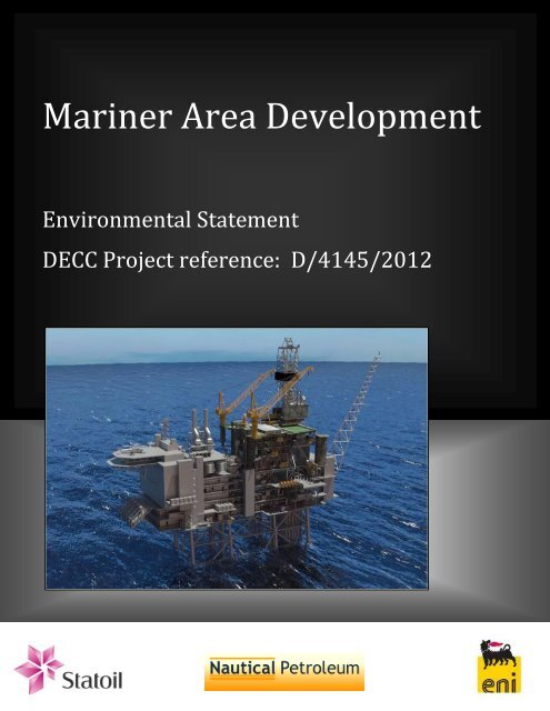
<strong>Mariner</strong> <strong>Area</strong> <strong>Development</strong><br />
Environmental Statement<br />
DECC Project reference: D/4145/2012
<strong>Mariner</strong> <strong>Area</strong> <strong>Development</strong> –<br />
Information Page<br />
INFORMATION PAGE<br />
Project name: <strong>Mariner</strong> <strong>Area</strong> <strong>Development</strong><br />
DECC Project reference: D/4145/2012<br />
Type of project: Field <strong>Development</strong><br />
Undertaker Name: <strong>Statoil</strong> (UK) Limited<br />
Address:<br />
One Kingdom Street<br />
London<br />
W2 6BD<br />
Licensees/Owners: Block 9/11a Block 9/11b<br />
Short description:<br />
Anticipated commencement<br />
of works:<br />
Date and reference number<br />
of any earlier Statement<br />
related to this project:<br />
Significant environmental<br />
impacts identified:<br />
<strong>Statoil</strong> (UK) Limited 65.1111% 92%<br />
ENI ULX Limited 20.0000% 8%<br />
ENI AEP Limited 6.6667% -<br />
ENI UKCS Limited 2.2222% -<br />
Alba Resources Limited (Nautical<br />
Petroleum)<br />
6.0000% -<br />
<strong>Statoil</strong> and its licence partners propose to develop the <strong>Mariner</strong> and<br />
<strong>Mariner</strong> East fields that are located in Quadrant 9 of the UK northern<br />
North Sea. The overall development proposal includes 50 wells and 92<br />
sidetracks at <strong>Mariner</strong> field and 4 wells at <strong>Mariner</strong> East, the installation of a<br />
production, drilling and quarters (PDQ) platform, a floating storage and<br />
offloading unit (FSU), a subsea drilling template, a Pipeline End Manifold,<br />
six Pipeline End Terminations, and associated infield, import and export<br />
pipelines.<br />
Wells at the <strong>Mariner</strong> field will be drilled from the PDQ platform and from a<br />
jack-up drilling rig located alongside for a period of 4 to 5 years, while the<br />
<strong>Mariner</strong> East wells will be drilled using a semi-submersible drilling rig. Oil<br />
from the <strong>Mariner</strong> <strong>Area</strong> <strong>Development</strong> will be separated from gas and water<br />
on the PDQ platform. Produced water from the development will be reinjected<br />
back into the reservoir. The oil will be exported to and stored in<br />
the FSU, and from there transferred to shuttle tankers for transport to<br />
shore. Produced gas will be used to fuel the turbines on the PDQ, with<br />
additional gas imported via a connection from the existing Vesterled<br />
pipeline.<br />
2015<br />
Not applicable<br />
None<br />
Statement prepared by: <strong>Statoil</strong> (UK) Limited and BMT Cordah Limited<br />
PM150-PMS-023-002 July 2012
<strong>Mariner</strong> <strong>Area</strong> <strong>Development</strong> –<br />
Information Page<br />
Intentionally blank page<br />
PM150-PMS-023-002 July 2012
<strong>Mariner</strong> <strong>Area</strong> <strong>Development</strong> -<br />
Table of Contents<br />
TABLE OF CONTENTS<br />
ABBREVIATIONS AND GLOSSARY iii<br />
NON-TECHNICAL SUMMARY xii<br />
1 INTRODUCTION 1-1<br />
1.1 Project Background and Purpose 1-1<br />
1.2 Purpose of the Environmental Statement 1-1<br />
1.3 Scope of the Environmental Assessment 1-3<br />
1.4 Structure of the Environmental Statement 1-5<br />
2 METHODOLOGY 2-1<br />
3 PROJECT DESCRIPTION 3-1<br />
3.1 Project Location and Overview 3-1<br />
3.2 Concept Selection Process 3-3<br />
3.3 The <strong>Mariner</strong> <strong>Development</strong> Concept 3-6<br />
3.4 Selected <strong>Development</strong> Concept 3-15<br />
3.5 Project Schedule 3-17<br />
3.6 Drilling 3-18<br />
3.7 Pipelines and Subsea Infrastructures 3-38<br />
3.8 <strong>Mariner</strong> PDQ and Ship-shaped FSU 3-51<br />
3.9 Potential Atmospheric Emissions from the <strong>Mariner</strong> <strong>Area</strong> <strong>Development</strong> 3-68<br />
3.10 Production Period 3-78<br />
3.11 Decommissioning 3-85<br />
4 ENVIRONMENTAL SETTING AND DESCRIPTION 4-1<br />
4.1 <strong>Mariner</strong> <strong>Area</strong> <strong>Development</strong> Field Surveys 4-1<br />
4.2 Physical environment 4-2<br />
4.3 Chemical environment 4-11<br />
4.4 Biological Environment 4-14<br />
4.5 Offshore Conservation <strong>Area</strong>s 4-30<br />
4.6 Coastal Conservation <strong>Area</strong>s 4-39<br />
4.7 Summary of the Environmental Sensitivities 4-43<br />
5 SOCIOECONOMIC SETTING 5-1<br />
5.1 Commercial fisheries 5-1<br />
5.2 Aquaculture 5-8<br />
5.3 Shipping traffic 5-9<br />
5.4 Oil and gas exploration activity and infrastructure 5-12<br />
5.5 Submarine cables and pipelines 5-14<br />
5.6 Renewable energy activity 5-14<br />
5.7 Ministry of Defence Activities (MoD) 5-16<br />
5.8 Gas and Carbon Capture and Storage Activities 5-16<br />
5.9 Dredging and Aggregate extraction 5-17<br />
5.10 Marine Archaeology and Wrecks 5-17<br />
5.11 Economic benefits from the proposed development 5-21<br />
PM150-PMS-023-002 i July 2012
<strong>Mariner</strong> <strong>Area</strong> <strong>Development</strong> -<br />
Table of Contents<br />
5.12 Summary of the socioeconomic receptors 5-21<br />
6 CONSULTATION 6-1<br />
6.1 Purpose and Method 6-1<br />
6.2 Concerns and Issues 6-2<br />
7 ENVIRONMENTAL RISK ASSESSMENT 7-1<br />
7.1 Introduction 7-1<br />
7.2 <strong>Mariner</strong> <strong>Area</strong> <strong>Development</strong> ENVID Workshop 7-1<br />
7.3 Risk Assessment Methodology 7-2<br />
7.4 Risk Assessment Findings 7-5<br />
7.5 Summary of Risk Assessment 7-6<br />
8 SIGNIFICANT IMPACTS 8-1<br />
8.1 Localised physical disturbance to the seabed arising from the<br />
drilling rig, platform and subsea installation activities 8-2<br />
8.2 Discharges to Sea 8-18<br />
8.3 Noise 8-41<br />
8.4 The Long-term Physical Presence of the PDQ, FSU, Drilling<br />
Rigs, Pipelines and other Subsea Structures on the Seabed 8-57<br />
8.5 Atmospheric Emissions arising from Drilling, Installation and Production<br />
Activities 8-66<br />
8.6 Accidental Hydrocarbon Release 8-76<br />
9 ENVIRONMENTAL MANAGEMENT 9-1<br />
9.1 Health, Safety and the Environment Policy 9-1<br />
9.2 The <strong>Statoil</strong> Management System 9-2<br />
9.3 Technical Standards 9-4<br />
9.4 Performance Monitoring 9-4<br />
9.5 Environmental Commitments 9-5<br />
10 CONCLUSIONS 10-1<br />
11 REFERENCES 11-1<br />
APPENDICES<br />
A – Legislation<br />
B – Well Design<br />
C – Baseline Figures<br />
D – Coastal Sensitivities<br />
E – Insignificant and Low Risk Impacts<br />
PM150-PMS-023-002 ii July 2012
<strong>Mariner</strong> <strong>Area</strong> <strong>Development</strong> -<br />
Abbreviations and Glossary<br />
ABBREVIATIONS<br />
Abbreviations<br />
3LPP 3-layer Polypropylene Coating<br />
µPa Micropascals<br />
AHV Anchor Handling Vessel<br />
ALARP As Low As Reasonably Practicable<br />
AOR Asset Owner Representative<br />
API American Petroleum Institute<br />
Ba Barium<br />
BAP Biodiversity Action Plan<br />
BaSO4<br />
Barium Sulphate<br />
BAT Best Available Technique<br />
bbl/day Barrels per day<br />
bbls Barrels<br />
BC Background Concentration<br />
BCLT Business Case Leadership Team<br />
BEP Best environmental practice<br />
BGS British Geological Survey<br />
BMIT Bottom Mounted Internal Turret<br />
BOD Biological Oxygen Demand<br />
BOP Blow-out Preventer<br />
BSI British Standard Institute<br />
CaCl Calcium Chloride<br />
CCS Carbon Capture and Storage<br />
Cd Cadmium<br />
CEFAS Centre for Environment, Fisheries and Aquaculture Science<br />
CFCs Chlorofluorocarbon gases<br />
CH4<br />
Methane<br />
CHARM Chemical Hazard Assessment & Risk Management<br />
CO Carbon Monoxide<br />
CO2<br />
Carbon Dioxide<br />
CoP Cessation of Production<br />
CPA Coastal Protection Act<br />
Cr Chromium<br />
Cu Copper<br />
CVP Capital Value Process<br />
dB Decibels<br />
DECC UK Government‟s Department of Energy and Climate Change<br />
PM150-PMS-023-002 iii July 2012
<strong>Mariner</strong> <strong>Area</strong> <strong>Development</strong> -<br />
Abbreviations and Glossary<br />
Abbreviations<br />
DEFRA Department of Environment, Food and Rural Affairs<br />
DES Drilling Equipment Set<br />
DG1 Decision Gate (1, 2, 3,.. etc.)<br />
DLE Dry Low Emission<br />
DMA Dead Man Anchor<br />
DNV Det Norse Veritas<br />
DP (vessel) Dynamic Positioning / Dynamically Positioned<br />
DPI EA <strong>Development</strong> and Production International, Europe and Asia<br />
DQ Drilling Quarters<br />
DSM Drilling Support Module<br />
DSV Dive Support Vessel<br />
DTI Department of Trade and Industry<br />
DWT Dead Weight Tonnage<br />
EC European Commission<br />
EDU Energy <strong>Development</strong> Unit<br />
EEA European Environment Agency<br />
EEC European Economic Community<br />
EEMS Environmental Emissions Monitoring System<br />
EIA Environmental Impact Assessment<br />
EMS Environmental Management System<br />
EMT Environmental Management Team<br />
ENVID Environmental Impact Identification<br />
EPRA Early Phase Risk Assessment<br />
EPC Engineering, Procurement and Construction<br />
EPS European Protected Species<br />
ERT Emergency Response Team<br />
ES Environmental Statement<br />
ESA Environmentally Sensitive <strong>Area</strong>s<br />
ESP Electric Submersible Pump<br />
EU European Union<br />
ETS Emissions Trading Scheme<br />
EUNIS The European Nature Information System<br />
FBE Fusion Bonded Epoxy<br />
FEED Front End Engineering Design<br />
FEPA Food and Environment Protection Act<br />
FLAGS Far North Liquids and Associated Gas System (pipeline)<br />
FLO Fisheries Liaison Officer<br />
FPSO Floating, Production, Storage and Offloading<br />
PM150-PMS-023-002 iv July 2012
<strong>Mariner</strong> <strong>Area</strong> <strong>Development</strong> -<br />
Abbreviations and Glossary<br />
FSL Fugro Survey Limited<br />
FSU Floating Storage Unit<br />
FUKA Frigg UK (pipeline)<br />
GBS Gravity Based Structure<br />
GRT Gross Register Tonnage<br />
H2S Hydrogen Sulphide<br />
Abbreviations<br />
HASS High Activity Sealed Source<br />
HAZID Hazard Identification Study<br />
HCFCs Hydrochlorofluorocarbon gases<br />
Hg Mercury<br />
HLV Heavy Lift Vessel<br />
HOCNS Harmonised Offshore Chemical Notification Scheme<br />
HP High Pressure<br />
HSE Health and Safety Executive<br />
HSE (Policy) Health, Safety and Environment<br />
HTV Heavy Transport Vessel<br />
Hz Hertz<br />
IBA Important Bird <strong>Area</strong>s<br />
ICES International Council for the Exploration of the Sea<br />
IMO International Maritime Organisation<br />
IoP Institute of Petroleum<br />
IOPP International Oil Pollution Prevention Certificate<br />
IPPC Integrated Pollution Prevention and Control<br />
ISO International Standards Organisation<br />
IUCN International Union for Conservation of Nature<br />
JNCC Joint Nature Conservation Committee<br />
KCl Potassium Chloride<br />
kHz kilohertz<br />
KISKA Kingfisher Information Service Cable Awareness<br />
LAT Lowest Astronomical Tide<br />
LCP Large Combustion Plant<br />
LNR Local Nature Reserve<br />
LR<br />
LS<br />
Received Sound Level<br />
Source Sound Level<br />
LSA Low Specific Activity<br />
LTOBM Low Toxicity Oil Based Mud<br />
LWD Logging While Drilling<br />
MARPOL The International Convention for the Prevention of Pollution from Ships<br />
PM150-PMS-023-002 v July 2012
<strong>Mariner</strong> <strong>Area</strong> <strong>Development</strong> -<br />
Abbreviations and Glossary<br />
max Maximum<br />
Abbreviations<br />
MCA Maritime and Coastguard Agency<br />
MCAA Marine and Coastal Access Act<br />
MCZ Marine Conservation Zone<br />
MDAC Methane Derived Authigenic Carbonate<br />
min Minimum<br />
MMO Marine Management Organisation<br />
MoD Ministry of Defence<br />
MPA Marine Protected <strong>Area</strong><br />
MS Marine Scotland<br />
MSA Marine (Scotland) Act<br />
MW Mega Watt<br />
MWD Measurement While Drilling<br />
N/A Not Applicable<br />
N2O Nitrous Oxide<br />
NaCl Sodium Chloride<br />
ND Not Detected<br />
NER New Entrants Reserve<br />
nm Nautical mile<br />
NNR National Nature Reserve<br />
NNS Northern North Sea<br />
NO No Data<br />
NOx<br />
NO2<br />
Oxides of nitrogen<br />
Nitrogen dioxide<br />
NORBRIT Norway-UK Joint Contingency Plan<br />
NORM Naturally Occurring Radioactive Materials<br />
NSA National Scenic <strong>Area</strong><br />
NSTF North Sea Task Force<br />
OBF Oil Based Fluid<br />
OBM Oil Based Mud<br />
OCNS Offshore Chemical Notification Scheme<br />
OIM Offshore Installation Manager<br />
OPEP Oil Pollution Emergency Plan<br />
OPF Organic Phase Fluids<br />
OPPC Oil Pollution Prevention and Control<br />
OPRC Oil Pollution Preparedness, Response and Co-operation<br />
OSCAR Oil Spill Contingency and Response model<br />
OSPAR Oslo and Paris Conventions for the protection of the marine environment of<br />
PM150-PMS-023-002 vi July 2012
<strong>Mariner</strong> <strong>Area</strong> <strong>Development</strong> -<br />
Abbreviations and Glossary<br />
the North-East Atlantic<br />
Abbreviations<br />
OVI Offshore Vulnerability Index<br />
Pa Pascals<br />
PAH Polycyclic Aromatic Hydrocarbons<br />
Pb Lead<br />
PCB Poly Chlorinated Biphenyls<br />
PCZ Preferred Conservation Zones<br />
PDQ Production Drilling Quarters<br />
PEXA (Military) Practice and Exercise <strong>Area</strong><br />
PLEM Pipeline End Manifold<br />
PLET Pipeline End Termination<br />
PON Petroleum Operations Notice<br />
POPA Prevention of Oil Pollution Act<br />
PPC Pollution, Prevention and Control<br />
PPD Public Participation Directive<br />
ppb Parts per Billion<br />
ppm Parts per Million<br />
ppt Parts per Thousand<br />
PTS Permanent Threshold Shift (to hearing)<br />
PW Produced Water<br />
PWA Pipeline Works Authorisation<br />
PWRI Produced Water Re-Injection<br />
Q Annual Quarter<br />
RA Reference <strong>Area</strong>s<br />
REACH Registration, Evaluation, Authorisation and Restriction of Chemicals<br />
ROV Remotely Operated Vehicle<br />
SAC Special <strong>Area</strong> of Conservation (c-candidate, d-draft, m-marine, p-possible)<br />
SAGE Scottish <strong>Area</strong> Gas Evacuation<br />
SAST Seabirds at Sea Team<br />
SBF Synthetic Based Fluid<br />
SBM Synthetic Based Muds<br />
SCANS Small Cetaceans Abundance in the North Sea and Adjacent waters<br />
SCI Sites of Community Importance<br />
SCOS Special Committee on Seals<br />
SDS Stern Discharge System<br />
SEA Strategic Environmental Assessment<br />
SEL Sound Exposure Level<br />
SEPA Scottish Environment Protection Agency<br />
PM150-PMS-023-002 vii July 2012
<strong>Mariner</strong> <strong>Area</strong> <strong>Development</strong> -<br />
Abbreviations and Glossary<br />
Abbreviations<br />
SFF Scottish Fishermans Federation<br />
SMRU Sea Mammal Research Unit<br />
SNH Scottish Natural Heritage<br />
SO2<br />
Sulphur Dioxide<br />
SOE State of the Environment<br />
SOPEP Shipboard Oil Pollution Emergency Plan<br />
The Representative of the Secretary of State for Energy and Climate<br />
SOSREP<br />
Change<br />
SOx<br />
Oxides of Sulphur<br />
SPA Special Protection <strong>Area</strong><br />
SPL Sound Pressure Level<br />
spp. Species (plural)<br />
SS Suspended Solids<br />
SSCV Semi-submersible Crane Vessel<br />
SSIV Subsea Isolation Valve<br />
SSSI Sites of Special Scientific Interest<br />
STL Submerged Turret Loading<br />
tan Tangent (function)<br />
THC Total Hydrocarbon Concentration<br />
TPD Technology, Projects and Drilling<br />
TR Technical Requirement<br />
UB Undersea Boat<br />
UHB Upheaval Buckling<br />
UKCS United Kingdom Continental Shelf<br />
UKHO United Kingdom Hydrographic Office<br />
UKOOA United Kingdom Offshore Operators Association<br />
UKOPP UK Oil Pollution Prevention<br />
UNESCO United Nations Educational, Scientific and Cultural Organization<br />
US United States<br />
VMR Voluntary Marine Reserves<br />
VMS Vessel Monitoring System<br />
VOC Volatile Organic Compound<br />
VSP Vertical Seismic Profiling<br />
WBM Water Based Mud<br />
WEEE Waste Electrical and Electronic Equipment Directive<br />
WHS World Heritage Site<br />
WWI World War I<br />
WWII World War II<br />
PM150-PMS-023-002 viii July 2012
<strong>Mariner</strong> <strong>Area</strong> <strong>Development</strong> -<br />
Abbreviations and Glossary<br />
GLOSSARY<br />
GLOSSARY<br />
Benthic fauna Organisms that live on, near, or in the bottom sediments of the seabed.<br />
Benthos See „Benthic Fauna‟.<br />
Biogeographic area An area of the Earth as defined by the flora and fauna found there.<br />
Block<br />
Blow-out preventer<br />
Centre for Environment,<br />
Fisheries and<br />
Aquaculture Science<br />
A North Sea acreage sub-division measuring approximately 10km x<br />
20km forming part of a quadrant, e.g. Block 21/05 is the 5th block of<br />
Quadrant 21.<br />
System of valves connected to the wellhead while drilling, which can be<br />
closed over the wellhead to prevent uncontrolled, sometimes explosive<br />
release of hydrocarbons from the wellbore.<br />
The government agency which approves chemicals for offshore use<br />
(amongst other functions).<br />
Cetaceans Aquatic mammals e.g. whales, dolphins and porpoise.<br />
Cephalopods<br />
Copepods<br />
dBHT<br />
Demersal<br />
DTI<br />
Diatoms<br />
Dinoflagellates<br />
Dispersant<br />
A class of mollusc characterised by bilateral body symmetry, reduction<br />
and internalisation of the shell and modification of the foot into<br />
tentacles. Examples include squid, cuttlefish, octopus and nautilus.<br />
Small crustaceans whose adult stage usually includes a single eye in<br />
the centre of the head. The free living marine species form a vital part<br />
of many marine food webs.<br />
A measure of the level of sound above the animal‟s hearing threshold,<br />
or its “perception level”.<br />
The zone that is the part of the sea or ocean (or deep lake) comprising<br />
the water column that is near to (and is significantly affected by) the<br />
seabed.<br />
Historically the regulatory authority for the offshore oil and gas industry,<br />
this agency has been dissolved and its energy-related responsibilities<br />
now fall to DECC.<br />
A group of eukaryotic algae that secrete characteristic cell walls<br />
consisting of two separate halves with an overlap between them.<br />
Diatoms reproduce by binary fission and often exist as single cells, but<br />
some species form colonies of chains.<br />
A diverse group of eukaryotic algae that often have two protruding<br />
flagellae used for propelling and directing the cell.<br />
An agent added to a suspension to improve the separation of particles.<br />
Dispersants added to spilled oil can help the oil break up into smaller<br />
droplets, increasing the exposed surface area and increasing the rate of<br />
degradation.<br />
PM150-PMS-023-002 ix July 2012
<strong>Mariner</strong> <strong>Area</strong> <strong>Development</strong> -<br />
Abbreviations and Glossary<br />
Dynamic Positioning<br />
Ecosystem<br />
Environmental Impact<br />
Assessment<br />
Environmental<br />
Management System<br />
Environmental<br />
Statement<br />
European protected<br />
species<br />
GLOSSARY<br />
A system of sensors and thrusters on a vessel which allows it to<br />
maintain position using satellite telemetry to adjust thrusters‟ direction<br />
and power.<br />
The physical environment and associated organisms that interact in a<br />
given area. There is no defined size for an ecosystem.<br />
A process to identify and assess the impacts associated with a<br />
particular activity, plan or project.<br />
A formal system which ensures that a company has control of its<br />
environmental performance.<br />
A report setting out the findings of an assessment of a project‟s<br />
environmental impacts.<br />
Species that are listed in Annex IV of the habitats directive, and are<br />
therefore protected from harm or disturbance by European law.<br />
Epibiotic An organism that lives on the surface of another organism.<br />
Epifauna Fauna inhabiting the surface of rocks, sediment or other fauna/flora.<br />
European Commission<br />
Fauna Animal life.<br />
Floating Storage Unit<br />
Flora Plant life.<br />
Body made up of commissioners from each EU country, responsible for<br />
representing the common European interest, with the power to instigate<br />
and apply changes in European law to all EU countries.<br />
A ship that is either purpose-built or heavily modified to receive<br />
hydrocarbons from offshore wells and store them until they are<br />
offloaded onto tankers for shipping ashore.<br />
Infauna Fauna that lives within sediments.<br />
Krill Shrimp-like marine animals, found in all oceans of the world.<br />
Marine Scotland<br />
Manifold<br />
Meroplankton<br />
Motile<br />
A government consultee and a lead marine management organisation<br />
in Scotland, bringing together the functions of the Fisheries Research<br />
Services ( Marine Scotland Science), the Scottish Fisheries Protection<br />
Agency ( Marine Scotland Compliance) and the Scottish Government<br />
Marine Directorate.<br />
The branch pipe arrangement which connects the valve parts of<br />
multiple pipes<br />
Plankton consisting of organisms at a certain life cycle stage (in<br />
particular larvae) that do not spend other stages of their lifecycles as<br />
plankton.<br />
Organisms that are able to propel themselves from one place to<br />
another.<br />
Niche An environment that is different from the surrounding area and that<br />
PM150-PMS-023-002 x July 2012
<strong>Mariner</strong> <strong>Area</strong> <strong>Development</strong> -<br />
Abbreviations and Glossary<br />
Notice to <strong>Mariner</strong>s<br />
GLOSSARY<br />
requires the organisms exploiting it to be specialised in ways not<br />
generally found in the surrounding area.<br />
Admiralty Notice to <strong>Mariner</strong>s contain all the corrections, alterations and<br />
amendments for the UK Hydrographic Office worldwide series of<br />
Admiralty Charts and Publications, published weekly as booklets, which<br />
are despatched directly from the UKHO.<br />
Organic Compounds Containing Carbon and Hydrogen.<br />
Pelagic<br />
Photic zone<br />
Any water in the sea that is not close to the bottom or near to the shore.<br />
Marine animals that live in the water column of coastal, ocean and lake<br />
waters, but not on the bottom of the sea or the lake.<br />
In this context defined as the upper 20 m of the water column which<br />
receives enough light for photosynthesis to occur.<br />
Phytoplankton Planktonic organisms that obtain energy through photosynthesis.<br />
Risk<br />
The combination of the probability of an event and a measure of the<br />
consequence.<br />
Salinity The salt content, in this case of a body of water.<br />
Sedentary<br />
Organisms that are essentially fixed in one location, and unable to<br />
move.<br />
Semi-diurnal Occurring twice daily.<br />
Stratification<br />
Sublittoral<br />
Substrate<br />
Surge<br />
Thermocline<br />
Tie-Back<br />
Separation of a body of water into two or more distinct layers due to<br />
differences in density or temperature.<br />
The area between the low water line and the edge of the continental<br />
shelf.<br />
In this context, any surface which could provide a habitat for an<br />
organism to live, i.e., a rock outcropping or area of sand.<br />
A rise in water level above that expected due to tidal effects alone; the<br />
primary causes are wind action and low atmospheric pressure.<br />
An area in the water column where there is a rapid temperature change<br />
with increasing depth. This is due to stratification between warmer, well<br />
mixed, less dense water in the surface layer and deeper, colder water<br />
below.<br />
Tie-backs connect new oil and gas discoveries to existing production<br />
facilities.<br />
Topography The surface features of the seabed.<br />
Transient<br />
UKCS<br />
In this context, animals that tend to move through areas rather than stay<br />
in a given area for a long period of time.<br />
United Kingdom Continental shelf. Waters in which the UK Government<br />
has jurisdiction over oil and gas activity<br />
PM150-PMS-023-002 xi July 2012
<strong>Mariner</strong> <strong>Area</strong> <strong>Development</strong> -<br />
Abbreviations and Glossary<br />
Umbilical<br />
Water column<br />
Christmas tree<br />
Zooplankton<br />
GLOSSARY<br />
Subsea pipe or cable connecting structures such as wellheads and<br />
subsea distribution units. Can be used to carry chemicals, hydraulic<br />
fluids and electricity supply.<br />
A theoretical column through a body of water from the surface to the<br />
sediments. This concept can be helpful when considering the different<br />
processes that occur at different depths.<br />
A structure fixed to the seabed which comprises a system of valves to<br />
control flow from a well into production flowlines.<br />
Broadly defined as heterotrophic (deriving energy from organic matter)<br />
planktonic organisms, although some protozoan zooplankton species<br />
can derive energy both from sunlight and by feeding on organic matter.<br />
PM150-PMS-023-002 xii July 2012
<strong>Mariner</strong> <strong>Area</strong> <strong>Development</strong> -<br />
Non-Technical Summary<br />
Introduction<br />
NON-TECHNICAL SUMMARY<br />
This non-technical summary outlines the findings of the environmental impact<br />
assessment conducted by <strong>Statoil</strong> (UK) Limited (<strong>Statoil</strong>) for the proposed <strong>Mariner</strong> <strong>Area</strong><br />
<strong>Development</strong>. The detailed assessment is presented within the Environmental<br />
Statement.<br />
The <strong>Mariner</strong> <strong>Area</strong> <strong>Development</strong> covers the <strong>Mariner</strong> field located in part Block 9/11a of<br />
the UK northern North Sea, together with the smaller nearby <strong>Mariner</strong> East field in part<br />
Block 9/11b (Figure i). The <strong>Mariner</strong> <strong>Area</strong> <strong>Development</strong> is located approximately 130<br />
km from the nearest UK coastline and approximately 40 km northwest from the<br />
UK/Norway median line.<br />
The concept for the <strong>Mariner</strong> <strong>Area</strong> <strong>Development</strong> comprises (Figure ii):<br />
Installation and operation of a fixed steel jacket platform at the <strong>Mariner</strong> field. The<br />
jacket will be secured by 24 piles hammered into the seabed;<br />
Installation and operation of a ship-shaped floating storage and offloading unit<br />
(FSU) at the <strong>Mariner</strong> field for the storage and transfer of crude and diluents. The<br />
FSU will be secured to the seabed by 12 to 16 suction piles or anchors;<br />
Two drilling centres. One drilling centre at the <strong>Mariner</strong> field, drilled via a platformmounted<br />
drilling unit plus a jack-up drilling unit. The other at the <strong>Mariner</strong> East field,<br />
drilled using a semi-submersible drilling rig;<br />
Fifty active wells and 92 sidetracks at the <strong>Mariner</strong> field, comprising 76 production<br />
wells, 64 produced water re-injectors, a make-up water well and a waste disposal<br />
well;<br />
Four production wells at the <strong>Mariner</strong> East field;<br />
A diluent import pipeline connecting the FSU to the <strong>Mariner</strong> platform;<br />
A crude export pipeline connecting the <strong>Mariner</strong> platform to the FSU;<br />
A gas import pipeline connecting the <strong>Mariner</strong> platform to the existing Vesterled<br />
pipeline;<br />
Six pipeline end terminals connecting subsea structures to each other;<br />
A pipeline end manifold connecting the gas import pipeline to the existing Vesterled<br />
pipeline;<br />
A subsea template at the <strong>Mariner</strong> East field;<br />
PM150-PMS-023-002 NTS - 1 July 2012
<strong>Mariner</strong> <strong>Area</strong> <strong>Development</strong> -<br />
Non-Technical Summary<br />
Figure i: Location of the <strong>Mariner</strong> <strong>Area</strong> <strong>Development</strong> in the northern North Sea<br />
PM150-PMS-023-002 NTS - 2 July 2012
<strong>Mariner</strong> <strong>Area</strong> <strong>Development</strong> -<br />
Non-Technical Summary<br />
A crude export pipeline connecting the <strong>Mariner</strong> East subsea template to the<br />
<strong>Mariner</strong> platform;<br />
A power and utility umbilical connecting the <strong>Mariner</strong> East subsea template to the<br />
<strong>Mariner</strong> platform;<br />
A 73 km fibre optic communication cable connecting the <strong>Mariner</strong> platform to the<br />
existing Heimdal platform on the Norwegian continental shelf;<br />
A subsea isolation valve (SSIV) in the gas import pipeline, close to the <strong>Mariner</strong><br />
platform; and<br />
Various supporting offshore vessels.<br />
<strong>Statoil</strong> plan to commence activities at the <strong>Mariner</strong> <strong>Area</strong> <strong>Development</strong> in Q3 2015, with<br />
first oil from the <strong>Mariner</strong> field expected in Q1 2017 and first oil from the <strong>Mariner</strong> East<br />
field in 2019. The <strong>Mariner</strong> <strong>Area</strong> <strong>Development</strong> is expected to have a field life of 40 years.<br />
Future<br />
tie-ins<br />
<strong>Mariner</strong> East<br />
Maureen Reservoir<br />
Battery limits for the <strong>Mariner</strong> <strong>Area</strong> design basis<br />
<strong>Mariner</strong> Heimdal<br />
Reservoir<br />
13 j-tubes<br />
<strong>Mariner</strong> PDQ<br />
PWRI<br />
<strong>Mariner</strong> Maureen<br />
Reservoir<br />
FSU<br />
Figure ii: Schematic of the proposed <strong>Mariner</strong> <strong>Area</strong> <strong>Development</strong><br />
Jack-up drilling<br />
rig<br />
PM150-PMS-023-002 NTS - 3 July 2012<br />
3 risers<br />
Diluent<br />
source<br />
The environmental impact assessment and the Environmental Statement have been<br />
prepared by <strong>Statoil</strong> in accordance with The Offshore Petroleum Production and<br />
Pipelines (Assessment of Environmental Effects) Regulations 1999 (as amended),<br />
which require the evaluation of projects likely to have a significant effect on the offshore<br />
environment. Additionally, the ES is formally required under these regulations because<br />
<strong>Mariner</strong> and <strong>Mariner</strong> East will be two new field developments.
<strong>Mariner</strong> <strong>Area</strong> <strong>Development</strong> -<br />
Non-Technical Summary<br />
The aim of the environmental impact assessment is to assess the potential<br />
environmental and socioeconomic impacts that may arise from the proposed <strong>Mariner</strong><br />
<strong>Area</strong> <strong>Development</strong> and to identify measures that will be put in place during design,<br />
construction and operations to prevent or minimise these impacts. The Environmental<br />
Statement summarises the environmental impact assessment process and outcome.<br />
The scope of the environmental impact assessment was developed and agreed during a<br />
scoping consultation process.<br />
Consultation has been an important part of the environmental impact assessment<br />
process. During the course of the environmental assessment, <strong>Statoil</strong> consulted with<br />
stakeholders potentially having an interest in the proposed <strong>Mariner</strong> <strong>Area</strong> <strong>Development</strong>.<br />
The relevant stakeholders were identified and contacted at an early stage to enable<br />
them to provide input into the environmental assessment and project design. Any<br />
concerns or comments raised during the consultations have been included and<br />
addressed within the Environmental Statement.<br />
Project Summary<br />
The proposed <strong>Mariner</strong> <strong>Area</strong> <strong>Development</strong> includes the installation of a new steel jacket<br />
platform at the <strong>Mariner</strong> field, with a permanent drilling rig on the jacket structure (Figure<br />
iii). A jack-up drilling rig positioned alongside the platform will assist drilling operations<br />
at <strong>Mariner</strong> for a period of 4 to 5 years.<br />
<strong>Statoil</strong> propose to drill a total of 50 wells and 92 sidetracks at the <strong>Mariner</strong> field. There<br />
are two reservoir formations at <strong>Mariner</strong>: one in the Maureen sands and one in the<br />
overlying Heimdal sands. The Maureen reservoir will be drilled and produced first, via<br />
single production wells and single produced water injector wells. The Heimdal reservoir<br />
will be drilled and produced later, with dual and single production wells and single<br />
produced water injectors.<br />
The <strong>Mariner</strong> East field will be developed by drilling 4 wells from a semi-submersible<br />
drilling rig, through a subsea template located 5 km south-east of the <strong>Mariner</strong> platform.<br />
Drilling at <strong>Mariner</strong> East will occur concurrently with drilling at the <strong>Mariner</strong> field.<br />
All the <strong>Mariner</strong> and <strong>Mariner</strong> East wells will be equipped with screens for sand control<br />
and with electric submersible pumps for lifting the heavy crude from the reservoirs.<br />
The top-hole sections of the wells will be drilled using seawater and high viscosity<br />
sweeps and subsequent sections will be drilled with water-based mud (WBM) and low-<br />
toxicity oil-base mud (LTOBM). <strong>Statoil</strong> currently have two options under consideration<br />
PM150-PMS-023-002 NTS - 4 July 2012
<strong>Mariner</strong> <strong>Area</strong> <strong>Development</strong> -<br />
Non-Technical Summary<br />
for the disposal for the LTOBM mud and cuttings generated from the reservoir sections;<br />
containment offshore with disposal onshore, or thermal treatment offshore.<br />
Figure iii: Illustration of the <strong>Mariner</strong> platform and jack-up drilling rig<br />
All the pipelines and umbilicals installed at the <strong>Mariner</strong> <strong>Area</strong> <strong>Development</strong> will be<br />
trenched and backfilled. Concrete mattresses and rock-dump will be used to protect the<br />
subsea infrastructure as required.<br />
The <strong>Mariner</strong> and <strong>Mariner</strong> East crude oil will be stabilised at the <strong>Mariner</strong> platform and<br />
transferred by pipeline to a ship-shaped Floating Storage and Offloading Unit, before<br />
being offloaded to shuttle tankers for transport to shore. A diluent will be used to reduce<br />
the crude oil viscosity and density. This diluent will be imported by shuttle tanker, stored<br />
on the FSU, transferred by pipeline to the <strong>Mariner</strong> platform and injected upstream of the<br />
electrical submersible pumps or upstream of the process for flow-assurance and<br />
separation purposes.<br />
PM150-PMS-023-002 NTS - 5 July 2012
<strong>Mariner</strong> <strong>Area</strong> <strong>Development</strong> -<br />
Non-Technical Summary<br />
Water produced from the reservoirs will normally be re-injected for pressure support and<br />
water flooding. During periods when produced water re-injection is not possible, the<br />
produced water will be treated to the required oil in water level and disposed overboard<br />
to sea. Produced gas will primarily be used for fuel, but will be insufficient to meet all of<br />
the platform‟s energy demands. Additional fuel gas will be imported from the Vesterled<br />
pipeline. Some produced gas will be flared.<br />
The <strong>Mariner</strong> <strong>Area</strong> <strong>Development</strong> is expected to produce a maximum of 76,000 bbls /<br />
calendar day of crude oil, with a total oil and diluents capacity of approximately 80,000<br />
bbls/day. The <strong>Mariner</strong> East field will produce a maximum of 22,000 bbls/ calendar day<br />
of crude oil, but at a time when <strong>Mariner</strong> production is below plateau rates, such that the<br />
combined development production rate will not exceed 76,000 bbls/day of crude or<br />
80,000 bbls / day of oil plus diluent.<br />
Environmental Sensitivities<br />
The <strong>Mariner</strong> <strong>Area</strong> <strong>Development</strong> is located in an area that is typical of the offshore<br />
regions of the northern North Sea where hydrographical, meteorological, geological and<br />
biological characteristics are relatively uniform over large areas. A summary of the<br />
environmental sensitivities in the vicinity of the <strong>Mariner</strong> <strong>Area</strong> <strong>Development</strong> are<br />
presented in Table i. Users of the area are mainly associated with oil and gas<br />
exploration and development, shipping and fishing.<br />
Table i: Summary of environmental sensitivities in the vicinity of the <strong>Mariner</strong> <strong>Area</strong><br />
<strong>Development</strong><br />
Physical environment<br />
Bathymetry: Seabed topography is flat with a gentle downward slope to the west. Water depths range<br />
between 97 and 112 m.<br />
Water masses, currents and meteorology:<br />
Typical current and wave patterns for the northern North Sea.<br />
Salinity and Temperature:<br />
Water column prone to stratify in the summer between June and September at depths of thermocline up to<br />
50 m. Salinity relatively uniform at all depths.<br />
Sediments type and features:<br />
Sediments are sand to muddy sand with occasional patches of coarser sediment and boulders.<br />
Chemical environment<br />
Seabed chemistry: There are no elevated levels of THC, PAH or heavy metals.<br />
Biological environment<br />
Plankton: Typical plankton community and seasonality for the northern North Sea.<br />
Benthic Fauna:<br />
Studies in the vicinity of the <strong>Mariner</strong> <strong>Area</strong> <strong>Development</strong> indicate that the benthos in the area is typical of<br />
benthic species for this part of the northern North Sea. No species or habitats of conservation importance<br />
were recorded during environmental baseline surveys.<br />
PM150-PMS-023-002 NTS - 6 July 2012
<strong>Mariner</strong> <strong>Area</strong> <strong>Development</strong> -<br />
Non-Technical Summary<br />
Table i (continued): Summary of environmental sensitivities in the vicinity of the<br />
<strong>Mariner</strong> <strong>Area</strong> <strong>Development</strong><br />
Biological environment (continued)<br />
Jan Feb Mar Apr May Jun Jul Aug Sep Oct Nov Dec<br />
Finfish and Shellfish Populations:<br />
The proposed development is located in spawning grounds of demersal species cod (Jan- Apr); haddock<br />
(Feb-May); whiting (Feb -June); saithe (Jan-Apr); Norway pout (Mar- May); Nephrops (throughout the year<br />
with peak Apr to Jun) and sandeel (Nov - Feb). The proposed development coincides with nursery areas for<br />
haddock, whiting, Norway pout, Nephrops, blue whiting, mackerel, European hake, ling, anglerfish, sandeels<br />
and herring.<br />
Marine Mammals<br />
Harbour porpoise, minke whale, killer whales and white- beaked dolphin have been recorded as present in<br />
the area with low to medium densities. The most sensitive periods for marine mammals in the area are from<br />
February to March, from June to September and in October when abundance of marine mammals in the<br />
area ranges from medium to very high.<br />
Seabirds:<br />
The most sensitive times of the year for seabirds are October to November when the seabird vulnerability is<br />
“very high”, and in January and July when the vulnerability is “high”.<br />
Habitats Directive: Annex I Habitats:<br />
No Annex I habitats or species of conservation concern have been found in the area such as Annex I<br />
Submarine structures made by leaking gases, pockmarks, MDAC derived outcrops, bubbling reefs and<br />
Annex I Reef such as stony, bedrock or biogenic reefs.<br />
Habitats Directive: Annex II Species:<br />
Harbour porpoise is the only Annex II species which has been sighted in the surroundings of the proposed<br />
development with very high abundance in February and high abundance in July.<br />
Key :<br />
ND ND ND<br />
Low Moderate High Very High ND No Data<br />
Assessment of potential impacts<br />
An assessment of the potential impacts associated with the <strong>Mariner</strong> <strong>Area</strong> <strong>Development</strong><br />
was conducted through identification of the key environmental issues during workshops<br />
and stakeholder consultation; evaluation of mitigation and management measures to<br />
reduce or remove negative environmental impacts; detailed assessment of key issues;<br />
and determination of residual impacts.<br />
PM150-PMS-023-002 NTS - 7 July 2012<br />
ND
<strong>Mariner</strong> <strong>Area</strong> <strong>Development</strong> -<br />
Non-Technical Summary<br />
The following potential impacts were identified as having the greatest significance to the<br />
environment:<br />
localised disturbance to the seabed;<br />
discharges to sea;<br />
underwater noise;<br />
long-term physical presence;<br />
atmospheric emissions; and<br />
accidental hydrocarbon release.<br />
Localised disturbance to the seabed<br />
The <strong>Mariner</strong> <strong>Area</strong> <strong>Development</strong> will result in disturbance to the seabed during from the<br />
placement of the platform jacket structure and the jack-up drilling rig on the seabed, the<br />
mooring system of the FSU, the subsea infrastructure, the pipeline installation vessels<br />
and the various support vessels.<br />
These operations will result in a short-term increase in water column turbidity as<br />
sediment is disturbed and could result in disturbance to fish and other organisms that<br />
live on or spawn on the seabed, through resuspension of sediment, and disturbance to<br />
benthic organisms and seabed spawning fish.<br />
Drilling rig operations are expected to have a short-term impact on approximately 0.032<br />
km 2 of seabed. Once the semi-submersible drilling rig anchors and the jack-up drilling<br />
rig spud cans are removed, the seabed areas disturbed by these operations are<br />
expected to recover naturally through the physical processes of sediment redistribution<br />
and biological processes of immigration and reproduction.<br />
The subsea infrastructure and the FSU moorings will remain on the seabed for the<br />
duration of the <strong>Mariner</strong> field life and represent a longer-term impact to the seabed. The<br />
estimated total area of impact is 3.2 km 2 .<br />
Seabed disturbance as a result of the <strong>Mariner</strong> <strong>Area</strong> <strong>Development</strong> will represent an<br />
additional impact. However, the majority of the seabed disturbance will result from the<br />
short-term operations of anchoring, trenching and backfill from which physical and<br />
biological recovery is expected to be rapid.<br />
PM150-PMS-023-002 NTS - 8 July 2012
<strong>Mariner</strong> <strong>Area</strong> <strong>Development</strong> -<br />
Non-Technical Summary<br />
Discharges to sea<br />
The <strong>Mariner</strong> <strong>Area</strong> <strong>Development</strong> will result in discharges to sea during the drilling (mud,<br />
cuttings and cement), installation and commissioning (leak testing of pipelines), and<br />
operational (produced water, production chemicals, deck drainage and ballast water)<br />
stages.<br />
Drilling<br />
Drilling of the <strong>Mariner</strong> <strong>Area</strong> <strong>Development</strong> wells will generate drill cuttings containing both<br />
water based muds and oil-based muds. The water-based mud and cuttings from the top<br />
sections will be discharged overboard and/or to the seabed. <strong>Statoil</strong> are considering<br />
either thermal treatment offshore, or containment and shipment back to shore for the<br />
low-toxicity oil based mud and cuttings from the lower well sections. If thermally treated<br />
the fine particles will be discharged to sea or shipped to shore.<br />
The main environmental issues arising from the discharge of the water based and<br />
thermally treated low-toxicity oil based muds and cuttings are likely to be smothering of<br />
benthic fauna on the seabed and fish spawning grounds. This may result in mortality to<br />
some benthic (seabed) organisms and temporary alteration to and loss of their benthic<br />
habitat. However, this habitat is likely to recover over time as a result of dispersion,<br />
dilution and breakdown of drilling chemicals, spreading and dispersion of cuttings, re-<br />
working of the sediment by burrowing organisms and recolonisation of cuttings by<br />
seabed benthic organisms typical of the <strong>Mariner</strong> area.<br />
There were no Annex I habitats identified in the area, with the nearest identified<br />
potential Methane Derived Authigenic Carbonate MDAC location situated approximately<br />
100 km from the proposed development. The results of cuttings dispersion modelling<br />
indicate that mud and cuttings could extend to 0.5 km from the discharge point,<br />
therefore the discharge of mud and cuttings is highly unlikely to have an impact on any<br />
Annex I habitats.<br />
There could be localised disturbance to seabed spawning species, of which the<br />
demersal living and spawning species Nephrops and sandeel potentially occur in the<br />
development area.<br />
Nephrops and sandeel spawning habitat may be smothered by cuttings, resulting in<br />
mortality or disturbance to these species. However, the sediment type in the<br />
development area is not optimal Nephrops habitat and it is unlikely that large areas of<br />
Nephrops habitat are present. Although the sandy sediments at the development area<br />
can provide a suitable sandeel habitat, a widespread distribution of sandeels over the<br />
PM150-PMS-023-002 NTS - 9 July 2012
<strong>Mariner</strong> <strong>Area</strong> <strong>Development</strong> -<br />
Non-Technical Summary<br />
North Sea would mean only a small fraction of the population is potentially affected by<br />
the development. Consequently, it is unlikely that there would be a significant impact on<br />
the Nephrops and sandeel populations.<br />
Installation and commissioning<br />
The permitted discharge of chemicals to the marine environment is a routine part of<br />
subsea installation operations. The quantities and types of chemicals to be used and<br />
discharged will be determined during the detailed design and will be selected in order to<br />
minimise hazards to the environment in accordance with the chemical permits obtained<br />
under Offshore Chemical Regulations 2002 (as amended). Where practicable <strong>Statoil</strong><br />
will give priority to the selection and use of low dosage, low risk chemicals and will<br />
minimise the total volume of discharges.<br />
During pipeline testing and commissioning, inhibited seawater may be released into the<br />
water column, with potential impacts on marine organisms in the immediate vicinity.<br />
Organisms most at risk would include planktonic and sessile organisms. The short-term<br />
permitted release of this water is not likely to have a significant impact on marine<br />
organisms but this will be fully risk-assessed when the specific chemical constituents<br />
and release locations are determined.<br />
Operations<br />
The discharge of produced water has the potential to impact upon marine organisms in<br />
the water column and on the seabed. The principal route for disposal of the treated<br />
produced water from the <strong>Mariner</strong> wells will be by re-injection. However, during periods<br />
when the produced water reinjection system is unavailable (e.g. during start up),<br />
produced water will be disposed of to sea. Before disposal, water will be treated to the<br />
regulatory oil-in-water standard of less than 30 mg/l.<br />
A range of chemicals will be used in the operation of the process and utilities systems.<br />
Chemicals will be stored within closed systems but will also be present in low<br />
concentrations within systems such as the oil and water phase of the process system.<br />
Underwater noise<br />
Underwater noise has the potential to affect marine mammals including cetaceans,<br />
several species of which are known to occur in the area. The <strong>Mariner</strong> <strong>Area</strong><br />
<strong>Development</strong> will generate underwater noise from, for example, drilling, piling, vessels<br />
and helicopter operations, as well as production operations.<br />
PM150-PMS-023-002 NTS - 10 July 2012
<strong>Mariner</strong> <strong>Area</strong> <strong>Development</strong> -<br />
Non-Technical Summary<br />
A detailed impact assessment of this noise, carried out according to Joint Nature<br />
Conservation Committee guidelines, indicates that cetaceans and other marine<br />
mammals are unlikely to be significantly affected, and there will be no injury to<br />
cetaceans from any associated noise source.<br />
Drilling and vessel noise is not predicted to cause more than minor disturbance to<br />
individual cetaceans. The most significant source of underwater noise is expected to be<br />
the piling of the platform jacket structure to the seafloor. Piling involves repeated impact<br />
of a pile using a hydraulic hammer in order to drive the pile to the desired depth.<br />
It is predicted that a small number of cetaceans may be disturbed during these piling<br />
operations but are likely to return to the area once piling has ceased. The zone of<br />
disturbance may extend to 64 km. The piling operations will last between a few hours to<br />
several days, so it is not expected this activity will cause significant negative impacts on<br />
cetacean populations. <strong>Statoil</strong> will apply best practice mitigation measures to minimise<br />
any risk of disturbance, including the use of marine mammal observers, passive<br />
acoustic monitors and soft-starts (slow increase in power) of the piling.<br />
Noise generated by vessels and drilling will contribute to the existing ambient noise<br />
already generated by vessels, shipping and construction in this well developed area of<br />
the North Sea. Therefore, there is unlikely to be a transboundary or global impact from<br />
the noise generated by the proposed development.<br />
Long-term physical presence<br />
The temporary and long term physical presence of the <strong>Mariner</strong> <strong>Area</strong> <strong>Development</strong><br />
platform, FSU, drilling rigs, pipelines, subsea infrastructure, and various support vessels<br />
have the potential to interfere with commercial fishing and other users of the sea.<br />
The development pipelines and umbilical will be trenched and buried. Once trenched<br />
and buried, the pipelines and umbilical are unlikely to represent a hazard to fishing gear.<br />
<strong>Statoil</strong> only plans to use spot (localised) rockdump as required along the length of the<br />
pipelines to protect against upheaval buckling. There may be a slightly increased risk of<br />
fishing gear interaction with areas of spot rockdump but the risk will be minimised by<br />
careful planning of trenching and backfilling operations to minimise the quantity of rock<br />
required. The profile of rockdump will be contoured to ensure that trawl gear can pass<br />
over it.<br />
The pipeline end manifold, pipeline end terminals, and <strong>Mariner</strong> East subsea template<br />
will all have fishing friendly protective structures designed to mitigate the potential for<br />
fishing gear interaction, and will be recorded on Admiralty charts and notified via<br />
PM150-PMS-023-002 NTS - 11 July 2012
<strong>Mariner</strong> <strong>Area</strong> <strong>Development</strong> -<br />
Non-Technical Summary<br />
„Kingfisher‟ reports. The platform and FSU will be surrounded by 500 m exclusion<br />
zones.<br />
Significant impacts on other users of the sea are not expected as fishing effort and value<br />
in the area are medium, shipping activity is low and the area is not important for military<br />
training.<br />
Atmospheric emissions<br />
During installation and start up activities, there will be gaseous atmospheric emissions<br />
from consumption of diesel fuel by vessels, helicopters and the drilling rigs. Helicopters<br />
will also consume helifuel.<br />
Operational emissions will arise from fuel consumption on the platform, drilling units and<br />
FSU, venting from tanker loading periodic venting and flaring, and fugitive emission<br />
sources.<br />
These emissions will cause short-term deterioration of local air-quality within a few<br />
metres of the point of the discharge. The exposed offshore conditions will promote the<br />
rapid dispersion of emissions, which are not expected to have a significant impact on<br />
any biological receptors in the area.<br />
From a global perspective, gaseous atmospheric emissions have the potential to<br />
contribute to greenhouse gas emissions and climate change. An assessment<br />
quantifying the significant sources of emissions associated with the <strong>Mariner</strong> <strong>Area</strong><br />
<strong>Development</strong> concluded that the development will represent a small proportion of<br />
emissions typically arising from UK offshore oil and gas production. <strong>Statoil</strong> is committed<br />
to reducing emissions to as low as reasonably practicable from all sources by using<br />
Best Available Technology and managing operations to maximise efficiency and,<br />
minimise fuel consumption .<br />
Accidental events<br />
Accidental spills of hydrocarbons are recognised as potentially damaging to the<br />
environment, although accidental events that could cause large-scale spillage of oil are<br />
unlikely to occur. <strong>Statoil</strong> will ensure that appropriate measures are in place during all<br />
phases of the development to reduce the risk of hydrocarbon spills to as low as<br />
reasonably practicable.<br />
Oil spill modelling has been conducted for the potential worst case spill scenarios, being<br />
a vessel collision with the FSU and a catastrophic event involving the FSU leading to<br />
loss of a majority of the oil inventory.<br />
PM150-PMS-023-002 NTS - 12 July 2012
<strong>Mariner</strong> <strong>Area</strong> <strong>Development</strong> -<br />
Non-Technical Summary<br />
The spatial extent of the resulting slick will vary depending on the loss scenario. The<br />
location of the <strong>Mariner</strong> <strong>Area</strong> <strong>Development</strong>, combined with the circulatory nature of<br />
prevailing currents, results in a low probability of oil reaching a shoreline. However, the<br />
worst case scenarios that have been modelled do have a possibility of causing oil<br />
beaching on Shetland or along the Norwegian coastline.<br />
The potential receptors that could be significantly impacted from an accidental spill<br />
event include seabirds and environmentally sensitive coastal areas.<br />
The potential risk to seabirds from oil and diesel pollution is through damage to feathers<br />
resulting in loss of mobility, buoyancy, insulation and waterproofing. Birds may also be<br />
at risk from toxicity through ingestion of hydrocarbons and may face starvation through<br />
depletion of food sources. Overall, the seabird vulnerability to oil pollution within the<br />
development area is „high‟ to „moderate‟.<br />
Several marine mammal species occur regularly in the development area, although only<br />
a few individuals are ever present at any one time. It is unlikely that the viability of any<br />
species would be impacted in the event of an accidental hydrocarbon spill associated<br />
with the <strong>Mariner</strong> <strong>Area</strong> <strong>Development</strong>.<br />
Fish species found within the area occur throughout the North Sea and no significant<br />
threat to fish populations from accidental hydrocarbon spill would be expected.<br />
Although fisherman and other sea users may be impacted by an oil spill, the impacts will<br />
likely only last while there is oil on the sea surface, which may temporarily restrict<br />
access. It is unlikely that there will be any long term socioeconomic impacts on these<br />
industries.<br />
An accidental release of chemicals could result in a localised impact around the<br />
discharge point. All chemicals will have been approved for use under the relevant<br />
chemical permit and so would be unlikely to present a significant environmental risk.<br />
<strong>Statoil</strong> will prepare Oil Pollution Emergency Plans to cover the <strong>Mariner</strong> and <strong>Mariner</strong> East<br />
operations in accordance with current DECC guidelines. <strong>Statoil</strong>‟s prevention measures,<br />
mitigation measures and contingency plans will consider all foreseeable spill risks and<br />
will ensure that the spill risk is reduced to as low as reasonably practicable. The<br />
contingency plans will ensure that an appropriate response is made to any spill in order<br />
to minimise any impact on the environment.<br />
A worst case release of crude and diesel oil from the total loss of FSU inventory would<br />
be likely to have a transboundary impact. However, an incident of this magnitude would<br />
have a very low probability of occurrence.<br />
PM150-PMS-023-002 NTS - 13 July 2012
<strong>Mariner</strong> <strong>Area</strong> <strong>Development</strong> -<br />
Non-Technical Summary<br />
Environmental Management<br />
<strong>Statoil</strong> has an Environment Management System which is fully compatible with the<br />
recognised environmental management standards including to ISO 14001.<br />
<strong>Statoil</strong> are committed to minimising the environmental impact of its activities. The<br />
activities associated with the <strong>Mariner</strong> <strong>Area</strong> <strong>Development</strong> will be conducted in<br />
accordance with <strong>Statoil</strong>‟s Environmental Management System. Continuous<br />
improvement in environmental performance is sought through effective project planning<br />
and implementation, emission reduction, waste minimisation, waste management, and<br />
energy conservation. <strong>Statoil</strong>, as the licence operator of the <strong>Mariner</strong> and <strong>Mariner</strong> East<br />
fields, retains ultimate liability and accountability for the field. Specific commitments for<br />
the <strong>Mariner</strong> <strong>Area</strong> <strong>Development</strong> are presented in the Environmental Statement.<br />
Conclusions<br />
The <strong>Mariner</strong> <strong>Area</strong> <strong>Development</strong> is not expected to result in significant environmental<br />
effects. The proposed development is very limited in extent and is located in an area<br />
which is typical of the northern North Sea in terms of habitat and marine life.<br />
The controls on operations have been designed to ensure that robust environmental<br />
safeguards will be put in place and preventative measures have been designed to<br />
minimise any potential environmental risks. <strong>Statoil</strong> believe that the measures that will<br />
be taken to minimise the environmental effects associated with the <strong>Mariner</strong> <strong>Area</strong><br />
<strong>Development</strong> represent an appropriate balance between protecting the environment and<br />
securing the economic benefits of the proposed project.<br />
PM150-PMS-023-002 NTS - 14 July 2012
<strong>Mariner</strong> <strong>Area</strong> <strong>Development</strong> -<br />
Chapter 1 Introduction<br />
1 INTRODUCTION<br />
1.1 Project Background and Purpose<br />
This Environmental Statement (ES) presents the findings of an Environmental Impact<br />
Assessment (EIA) for the proposed development of the <strong>Mariner</strong> <strong>Area</strong> <strong>Development</strong> which<br />
consists of the <strong>Mariner</strong> field, located within Block 9/11a, and the <strong>Mariner</strong> East field,<br />
located within Block 9/11b, both in the UKCS northern North Sea. As the licence operator<br />
of these blocks, <strong>Statoil</strong> (UK) Limited (<strong>Statoil</strong>) and their commercial partners are proposing<br />
to develop the <strong>Mariner</strong> and the <strong>Mariner</strong> East discoveries. Table 1.1 provides a breakdown<br />
of the commercial interests in Blocks 9/11a and 9/11b.<br />
Table 1.1: Summary of block interests<br />
Company Block 9/11a Block 9/11b<br />
<strong>Statoil</strong> (UK) Limited 65.1111% 92.0%<br />
ENI ULX Limited 20.0000% 8.0%<br />
ENI AEP Limited 6.6667% -<br />
ENI UKCS Limited 2.2222% -<br />
Alba Resources Limited (Nautical<br />
Petroleum)<br />
1.2 Purpose of the Environmental Statement<br />
6.0000% -<br />
This ES has been prepared by <strong>Statoil</strong> (UK) Limited (<strong>Statoil</strong>) in conjunction with BMT<br />
Cordah Limited. An ES is a means of submitting to the regulatory authority, statutory<br />
consultees, non-government organisations and the wider public the findings of an<br />
assessment of the likely effects on the environment of the proposed activity. The <strong>Mariner</strong><br />
<strong>Area</strong> <strong>Development</strong> ES is a key management document for the <strong>Mariner</strong> <strong>Area</strong> <strong>Development</strong><br />
Project and has been prepared in line with <strong>Statoil</strong>’s HSE Policy.<br />
Submission of an ES to the Department of Energy and Climate Change (DECC) is a legal<br />
requirement for projects designed to produce 500 tonnes (3,750 bbls) or more per day of<br />
oil, or 500,000 cubic metres or more of gas per day, under the Offshore Petroleum<br />
Production and Pipelines (Assessment of Environmental Effects) Regulations 1998 (as<br />
amended).<br />
The ES is also prepared in support of the Field <strong>Development</strong> Plans for the <strong>Mariner</strong> and<br />
<strong>Mariner</strong> East fields. In addition to the ES, <strong>Statoil</strong> will prepare Petroleum Operation Notices<br />
(PONs) 15Bs, 15Cs and 15D for submittal to DECC for chemical use and discharge during<br />
the initial stages of the proposed operations at the <strong>Mariner</strong> <strong>Area</strong> <strong>Development</strong>. These will<br />
PM150-PMS-023-002 1 - 1 July 2012
<strong>Mariner</strong> <strong>Area</strong> <strong>Development</strong> -<br />
Chapter 1 Introduction<br />
be prepared once details of chemical usage and discharge have been finalised. Figure<br />
1.1 illustrates the EIA process and PON requirements for the <strong>Mariner</strong> <strong>Area</strong> <strong>Development</strong>.<br />
<strong>Mariner</strong> <strong>Area</strong> <strong>Development</strong><br />
<strong>Mariner</strong> Field <strong>Mariner</strong> East Field<br />
Environmental Statement (ES) required under:<br />
• Offshore Petroleum Production and Pipe-lines (Assessment of Environmental<br />
Effect) Regulations 1998 (as amended)<br />
• Petroleum Act 1998 (supporting Field <strong>Development</strong> Plans)<br />
Petroleum Operation Notice (PON) 15 preparation:<br />
PON 15B Application for direction to drill the wells under Section 6(2)<br />
Application for a chemical permit to use and discharge chemicals<br />
during drilling operations<br />
PON15C Application for direction for a pipeline under Section 6(2)<br />
Application for a chemical permit to use and discharge chemicals<br />
during pipeline operations<br />
PON15D Application for direction for production operations under Section<br />
6(2)<br />
Application for a chemical permit to use and discharge chemicals<br />
during production operations<br />
Figure 1.1: EIA and PON requirements for the initial stages of the <strong>Mariner</strong> <strong>Area</strong><br />
<strong>Development</strong><br />
An EIA is an important management tool used by <strong>Statoil</strong> to ensure that environmental<br />
considerations are incorporated into all project-planning and decision-making. At the<br />
heart of the EIA is a hazards and effects management process that comprises five main<br />
stages:<br />
characterisation of the receiving environment;<br />
identification of potential environmental impacts associated with the project;<br />
PM150-PMS-023-002 1 - 2 July 2012
<strong>Mariner</strong> <strong>Area</strong> <strong>Development</strong> -<br />
Chapter 1 Introduction<br />
assessment of the significance of potential impacts from planned activities;<br />
assessment of the significance of potential impacts from accidental or unplanned<br />
events; and<br />
development of controls to eliminate or reduce the severity of identified impacts, and<br />
plans to avoid or reduce the likelihood of accidental or unplanned events.<br />
In conducting the EIA, consideration was given to potential local, regional, cumulative and<br />
transboundary effects from the offshore development operations.<br />
The EIA is an evaluation process which enables those responsible for the project, other<br />
interested parties (referred to as stakeholders) and the statutory authorities to understand<br />
the significant environmental impacts and risks (potential impacts), the methods of<br />
managing risk and the benefits that are likely to occur. This allows the stakeholders to<br />
contribute to the decisions that are taken about the project.<br />
The EIA also helps those responsible for the project to select the plans, programmes,<br />
designs, technologies, management practices, contractors and personnel that are<br />
appropriate for the project and the environment in which the project occurs. In cases<br />
where oil and gas projects impinge upon a potential candidate Special <strong>Area</strong> of<br />
Conservation (cSAC), an ‘Appropriate Assessment’ may be required under The Offshore<br />
Petroleum Activities (Conservation of Habitats) Regulations 2001 (as amended).<br />
1.3 Scope of the Environmental Assessment<br />
<strong>Statoil</strong> are planning to develop the <strong>Mariner</strong> (Heimdal and Maureen reservoirs) and <strong>Mariner</strong><br />
East fields as the <strong>Mariner</strong> <strong>Area</strong> <strong>Development</strong>.<br />
The <strong>Mariner</strong> field is located in Block 9/11a while the <strong>Mariner</strong> East field is located within<br />
Block 9/11b, both within the UK northern North Sea (Figure 1.2). The <strong>Mariner</strong> field lies<br />
approximately 5 km north west of <strong>Mariner</strong> East field. The nearest oil production facility to<br />
the <strong>Mariner</strong> and <strong>Mariner</strong> East fields is the Beryl oil field in Block 9/13, located<br />
approximately 18 km to the east (Figure 1.2).<br />
The <strong>Mariner</strong> field will be developed by installing a new steel jacket platform, with 60 well<br />
slots, a maximum of 50 simultaneously active wells and 92 sidetrack wells, drilled via a<br />
jack-up drilling rig and the new platform, and installing a new gas import pipeline. The<br />
<strong>Mariner</strong> East field will be developed by drilling 4 wells from a semi-submersible drilling rig,<br />
through a subsea template.<br />
PM150-PMS-023-002 1 - 3 July 2012
<strong>Mariner</strong> <strong>Area</strong> <strong>Development</strong> -<br />
Chapter 1 Introduction<br />
Figure 1.2: Location of the <strong>Mariner</strong> <strong>Area</strong> <strong>Development</strong> in the northern North Sea<br />
Drilling, production and processing at the <strong>Mariner</strong> field will be undertaken by an integrated<br />
Production Drilling Quarter (PDQ) platform, in addition to a separate jack-up drilling rig<br />
positioned next to the platform. <strong>Statoil</strong> envisage the jack-up drilling rig will be required at<br />
PM150-PMS-023-002 1 - 4 July 2012
<strong>Mariner</strong> <strong>Area</strong> <strong>Development</strong> -<br />
Chapter 1 Introduction<br />
the <strong>Mariner</strong> field to assist with the proposed drilling programme for a period of 5 years.<br />
Drilling at the <strong>Mariner</strong> East field will be undertaken by a semi-submersible drilling rig<br />
positioned over a subsea template.<br />
The <strong>Mariner</strong> and <strong>Mariner</strong> East crude oil will be stabilised and transported to a ship-shaped<br />
Floating Storage Unit (FSU), before being offloaded to shuttle tankers for transport to<br />
shore. A diluent will be used at the <strong>Mariner</strong> <strong>Area</strong> <strong>Development</strong> to reduce the <strong>Mariner</strong><br />
crude oil viscosity and density. This diluent will be stored on the FSU and injected<br />
upstream of the electrical submersible pumps (ESP) or upstream of the process for flow-<br />
assurance and separation purposes.<br />
Water produced from the <strong>Mariner</strong> <strong>Area</strong> <strong>Development</strong> will be, after treatment, re-injected<br />
into the <strong>Mariner</strong> reservoirs for pressure support. Alternatively, when injection is not<br />
possible, the produced water will be treated to required oil in water level and disposed to<br />
sea. Produced gas will be used for fuel, however, it will be insufficient to meet all the<br />
facility’s energy demands, so a source of gas import is required. Supplemental gas for<br />
fuel will be imported from the Vesterled pipeline. The <strong>Mariner</strong> FSU and risers have a<br />
design life of 30 years.<br />
Key environmental UK legislation applicable to the <strong>Mariner</strong> <strong>Area</strong> <strong>Development</strong> is listed<br />
below and summarised in Appendix A.<br />
Offshore Petroleum Production and Pipelines (Assessment of Environmental Effects)<br />
Regulations 1999 (as amended).<br />
Petroleum Act 1998 (in support of the Field <strong>Development</strong> Plans).<br />
Offshore Chemicals Regulations 2002 (as amended).<br />
Offshore Petroleum Activities (Conservation of Habitats) Regulations 2001 (as<br />
amended).<br />
Department of Energy and Climate Change (DECC) Guidance Notes 2009.<br />
1.4 Structure of the Environmental Statement<br />
The ES is structured in the following manner:<br />
Non-Technical Summary: An Executive Summary of the EIA presented in non-technical<br />
language.<br />
Section 1 Introduction: An introductory discussion of the policy, legal, and regulatory<br />
framework within which the EIA is carried out.<br />
PM150-PMS-023-002 1 - 5 July 2012
<strong>Mariner</strong> <strong>Area</strong> <strong>Development</strong> -<br />
Chapter 1 Introduction<br />
Section 2 Methodology: A description of the methods used to complete the EIA.<br />
Section 3 Project Description: A brief description of the project alternatives, and<br />
selected design including the drilling, construction and operational phases, a description of<br />
the production processes and an explanation of how the project will modify the existing<br />
environment.<br />
Section 4 Environmental Baseline: A description of the current state of the physical and<br />
biological offshore environment of the <strong>Mariner</strong> <strong>Area</strong> <strong>Development</strong>, including in particular<br />
the components that are likely to be affected (climatic factors, air, water, seabed, flora,<br />
fauna, human activities and culture).<br />
Section 5 Socioeconomic Environment: A description of commercial fisheries, shipping,<br />
oil and gas activities, communication cables, wrecks, dredging and military activities in the<br />
<strong>Mariner</strong> <strong>Area</strong> <strong>Development</strong>.<br />
Section 6 Consultation: A summary of the informal consultation that was held between<br />
<strong>Statoil</strong> and the statutory and non-statutory stakeholders, and the issues raised or<br />
discussed.<br />
Section 7 Environmental Risk Assessment: The methodology adopted for predicting<br />
and assessing likely positive and negative impacts from planned operations, a list<br />
screening the significance of impacts associated with the project, and a quantitative<br />
description of the significant residual negative impacts of the proposed project on the<br />
environment. The section also presents the methodology adopted for assessing the<br />
effects of accidental or unplanned events, and an assessment of the potential significance<br />
of selected example accidental or unplanned scenarios.<br />
Section 8 Assessment of Potential Impacts: A description of the potential sources of<br />
significant impact from the project, an indication of the increase in those sources due to<br />
the modification of existing installations, and an estimate of the scale of the emissions,<br />
discharges, wastes and disturbance factors connected with the project.<br />
Section 9 Environmental Management: An outline of the arrangements that will be put<br />
in place to ensure that the mitigation and control measures identified in the environmental<br />
statement are implemented. The section also states <strong>Statoil</strong>’s environmental commitments<br />
for the lifetime of the <strong>Mariner</strong> <strong>Area</strong> <strong>Development</strong> project.<br />
Section 10 Conclusions: A summary of the findings of the EIA.<br />
Appendices: Supporting information and studies relevant to the EIA.<br />
PM150-PMS-023-002 1 - 6 July 2012
<strong>Mariner</strong> <strong>Area</strong> <strong>Development</strong> -<br />
Chapter 2 Methodology<br />
2 METHODOLOGY<br />
The EIA methodology systematically identifies the significant environmental impacts and<br />
risks (potential impacts) of the proposed project, assesses the requirement for risk-<br />
reduction measures and provides an Environmental Management Plan to facilitate the<br />
adoption of these measures throughout the project. This assessment aligns with the<br />
requirements set out in the Schedule to the Offshore Petroleum Production and Pipelines<br />
(Assessment of Environmental Effects) Regulations 1999 (as amended), and associated<br />
Guidance Notes on the interpretation of the regulations (DECC, 2011b). Figure 2.1<br />
illustrates the principal stages in the EIA process.<br />
In the present context, a significant impact or risk can be defined as one requiring<br />
management action to be taken to:<br />
avoid or minimise potentially adverse consequences for the environment, the public<br />
or the project;<br />
resolve the concerns of stakeholders; and/or<br />
fulfil the requirements of environmental legislation and company policy.<br />
Management actions will include:<br />
controls, i.e. methods for reducing the likelihood of the events that will lead to<br />
environmental impact (e.g. vessel collisions causing oil spills);<br />
mitigation, i.e. methods for eliminating or reducing adverse environmental<br />
consequences (e.g. oil spill clean-up and response techniques); and<br />
other actions (e.g. awareness and training).<br />
The approach has been adapted from the British Standard BS8800 (BSI, 1996), the Oil<br />
and Gas UK Guidelines on Risk Assessment (UKOOA, 1999 and 2000) and the<br />
international environmental management standard BS EN ISO 14001 (BSI, 2004).<br />
The sections in the remainder of the ES provide individual method statements for the<br />
processes used in the EIA for data gathering and interpretation, consultation, risk<br />
assessment, evaluation of significant impacts and mitigation, and the evaluation of the<br />
environmental management framework to be used throughout the project lifecycle.<br />
PM150-PMS-023-002 2 -1 July 2012
<strong>Mariner</strong> <strong>Area</strong> <strong>Development</strong> -<br />
Chapter 2 Methodology<br />
Project and<br />
Environmental<br />
Context<br />
Project Description<br />
• Identification of potential causes of<br />
environmental impact and risk<br />
• Highlight critical data gaps<br />
Risk Identification<br />
and Assessment<br />
Exclusion of trivial impacts and risks<br />
from further investigation in the EIA<br />
Detailed<br />
Assessment of<br />
Significant<br />
Impact and<br />
Risks<br />
Justification for Project<br />
Options considered<br />
• Justification for proposed<br />
alternative<br />
• Elimination of less appropriate<br />
alternatives<br />
Environmental Risk Assessment<br />
• Application of defined assessment<br />
criteria<br />
• Justification for the assessment made<br />
Focus investigation on significant<br />
impacts and risks<br />
Detailed assessment of:<br />
• Causes and consequences of environmental impacts<br />
from planned activities<br />
• Causes and potential consequences of oil spills and<br />
other unplanned events<br />
• Proposed environmental safeguards<br />
• Response to concerns and issues raised by consultees<br />
• Temporary and lasting environmental impact and risks<br />
Environmental Management Systems for:<br />
• Assuring compliance with environmental legislation and<br />
<strong>Statoil</strong> (UK) Limited<br />
• Maintaining environmental awareness<br />
• Implementing project-specific safeguards<br />
• Prevention and contingency planning<br />
• Monitoring and assurance of environmental performance<br />
• Providing feedback to interested parties<br />
Project-Specific Environmental Management Plan:<br />
• Checklist specifying the environmental management<br />
actions to be implemented during the project<br />
Balanced conclusions on:<br />
• Adequacy of EIA as a basis for decision making<br />
• Benefits, impacts and risks<br />
• Confidence in project techniques and safeguards<br />
• Resolution of the concerns of consultees<br />
• Implementation of systems and safeguards during the<br />
project<br />
Consultation throughout EIA with:<br />
• Recognised environmental and technical<br />
specialists<br />
• Organisations with statutory responsibility<br />
for the environment<br />
• Individuals and organisations with a<br />
legitimate interest in the environment of<br />
the project<br />
Environmental Description<br />
• Identification of sensitive components in the<br />
physical, chemical, biological and socio-economic<br />
environment<br />
• Highlight critical data gaps<br />
Elimination from the project of<br />
unacceptable impacts and risks<br />
Figure 2.1: Principal stages in the Environmental Impact Assessment process<br />
PM150-PMS-023-002 2 -2 July 2012
<strong>Mariner</strong> <strong>Area</strong> <strong>Development</strong> -<br />
Chapter 3 Project Description<br />
3 PROJECT DESCRIPTION<br />
The <strong>Mariner</strong> <strong>Area</strong> <strong>Development</strong> will produce oil from the <strong>Mariner</strong> oil field and from the<br />
smaller nearby <strong>Mariner</strong> East oil field.<br />
Each of these fields comprises two shallow reservoirs, one in the Maureen formation and<br />
one in the overlying Heimdal formation. These reservoirs are characterised by dense,<br />
highly viscous oils, the Maureen oil having an API gravity of approximately 14.2 and the<br />
Heimdal oil having an API gravity of approximately 12.1. Production of these dense,<br />
viscous crudes will require use of down-hole pumps for artificial lift, plus blending with a<br />
light oil (“diluent”) to assist fluid flow.<br />
In the case of <strong>Mariner</strong>, oil will be produced from both reservoirs, but only the Maureen<br />
reservoir will be produced at <strong>Mariner</strong> East.<br />
3.1 Project Location and Overview<br />
The two oil fields are located in the UK northern North Sea, the <strong>Mariner</strong> field being in part-<br />
Block 9/11a and the <strong>Mariner</strong> East field in part-Block 9/11b approximately 5 km to the south<br />
east (Figure 3.1). The nearest existing oil production facility is on the Beryl oil field in<br />
Block 9/13, located approximately 18 km to the east.<br />
The <strong>Mariner</strong> field will be operated by <strong>Statoil</strong> under Licence P.335 (see Figure 3.2), with<br />
joint ownership between <strong>Statoil</strong> (65.1111%), ENI (28.8889%) and Alba Resources<br />
(Nautical Petroleum) (6%). The <strong>Mariner</strong> East field will be operated by <strong>Statoil</strong> under<br />
Licence P.726, with joint ownership between <strong>Statoil</strong> (92%) and ENI (8%).<br />
Since the oil accumulations were first discovered in 1981, 4 exploration and 10 appraisal<br />
wells have been drilled in Block 9/11. Including side-tracks there have been 19 reservoir<br />
penetrations in total.<br />
The <strong>Mariner</strong> field is expected to produce a maximum of 76,000 bbls/calendar day of crude<br />
oil, and the <strong>Mariner</strong> East field is expected to produce a maximum of 22,000 bbls/calendar<br />
day of crude oil. <strong>Mariner</strong> East will produce at a time when <strong>Mariner</strong> field production is off<br />
plateau, such that the combined total production from the <strong>Mariner</strong> <strong>Area</strong> <strong>Development</strong> is<br />
not expected to exceed 76,000 bbls/calendar day of crude oil.<br />
The production systems will be designed for 76,000 bbls/day of crude oil, 80,000 bbls/day<br />
of crude oil plus diluent, and 320,000 bbls/day of total fluids (being crude oil, diluent and<br />
produced water combined).<br />
PM150-PMS-023-002 3 - 1 July 2012
<strong>Mariner</strong> <strong>Area</strong> <strong>Development</strong> -<br />
Chapter 3 Project Description<br />
Figure 3.1: Location of <strong>Mariner</strong> and <strong>Mariner</strong> East within the northern North Sea<br />
PM150-PMS-023-002 3 - 2 July 2012
<strong>Mariner</strong> <strong>Area</strong> <strong>Development</strong> -<br />
Chapter 3 Project Description<br />
Figure 3.2: Schematic of the <strong>Mariner</strong> and <strong>Mariner</strong> East reservoirs, possible targets<br />
and previous wells<br />
3.2 Concept Selection Process<br />
3.2.1 <strong>Statoil</strong>’s Capital Value Process<br />
The Capital Value Process (CVP) is <strong>Statoil</strong>‟s decision process for investment projects. It<br />
is described in the <strong>Statoil</strong> Book, and in the <strong>Statoil</strong> governing document FR05 “Functional<br />
Requirements – Project <strong>Development</strong>”. The CVP is as shown diagrammatically in Figure<br />
3.3. <strong>Statoil</strong> became operator of the <strong>Mariner</strong> licence area in late 2007 following a process<br />
of acquisitions and mergers. The main path of the CVP was entered at the “business<br />
planning” stage. This and subsequent stages of the CVP may be explained as follows:<br />
Business Planning (“Feasibility”)<br />
The work in this phase frames the business case and develops the business objectives. It<br />
also identifies a technically and operationally feasible investment project concept, and<br />
verifies through economic and stakeholder analysis that further development is justified.<br />
Decision Gate (DG)1 is an approval to further mature the investment project in the<br />
concept planning phase.<br />
PM150-PMS-023-002 3 - 3 July 2012
<strong>Mariner</strong> <strong>Area</strong> <strong>Development</strong> -<br />
Chapter 3 Project Description<br />
Acquisitions /farm-ins/mergers<br />
Screening<br />
business<br />
opportunities<br />
Bid<br />
preparations<br />
Business<br />
identification<br />
DGA DGB DGC<br />
DG0 DG1 DG2 DG3 DG4<br />
Concession/<br />
Negotiations<br />
Business<br />
planning<br />
Figure 3.3: The <strong>Statoil</strong> Capital Value Process<br />
Concept Planning<br />
Concept<br />
planning<br />
Definition Execution Operations<br />
The work in this phase establishes a clear basis for the investment project, selects a<br />
preferred commercial and technical development concept, and matures the business case<br />
to the required level for DG2. DG2 is the main decision gate before significant external<br />
resources are involved, and is the approval to take the project into the definition phase.<br />
Definition<br />
The main focus in this phase is to mature the project to the required level for a final<br />
investment decision to be made. This phase includes Front End Engineering Design<br />
(FEED) of the facilities. DG3 represents the sanction of the investment project.<br />
Execution<br />
The purpose of the execution phase is to realise the business case through detailed<br />
design, fabrication, installation and commissioning. DG4 will be passed once the facilities<br />
are ready to start operation, and the receiving asset accepts that the facilities are ready for<br />
hand-over.<br />
3.2.2 Quality Assurance within the CVP<br />
Extensive quality processes are incorporated into the CVP. In particular, FR05 specifies<br />
an organizational structure for projects, the activities that must be conducted during each<br />
project phase, and a programme of meetings and reviews.<br />
PM150-PMS-023-002 3 - 4 July 2012
<strong>Mariner</strong> <strong>Area</strong> <strong>Development</strong> -<br />
Chapter 3 Project Description<br />
Organisation<br />
The relevant business area – which in the case of <strong>Mariner</strong> is <strong>Development</strong> and Production<br />
International, Europe and Asia (DPI EA) – delegates responsibility and provides the<br />
necessary mandate to an “Asset Owner”.<br />
Responsibilities for the asset owner are to:<br />
• establish the business case objectives;<br />
• establish a steering committee and a project organisation;<br />
• establish quality assurance and company assistance;<br />
• establish risk management processes for the project;<br />
• establish relevant project benchmarks;<br />
• establish the decision documentation;<br />
• prepare a decision memo; and<br />
• recommend that the project either pass a decision gate or ceases.<br />
The asset owner appoints an “Asset Owner Representative” (AOR) to deliver these<br />
outcomes on his or her behalf. Reporting to the AOR is a Business Case Leadership<br />
Team (BCLT) comprising the heads of the three sub-projects - petroleum technology,<br />
drilling and wells and facilities - together with the functions of quality and risk<br />
management, integration and HSE/Authority Liaison. Facilities sub-project includes a team<br />
dedicated to health, safety and environment (HSE) in facilities design.<br />
Discipline engineers within the sub-projects are drawn from the Technology, Projects and<br />
Drilling (TPD) division of <strong>Statoil</strong>. These engineers conduct the detailed technical work<br />
according to the <strong>Statoil</strong> governing documents known as “Technical Requirements”, TRs.<br />
Review Processes<br />
At the beginning of each phase a meeting between key internal stakeholders is held to<br />
discuss the business case and business drivers, and give key forward-looking directions<br />
for the project.<br />
A Steering Committee acts as an advisory group for the asset owner. It meets regularly to<br />
secure alignment between business areas regarding definition, context and scope of the<br />
business case.<br />
PM150-PMS-023-002 3 - 5 July 2012
<strong>Mariner</strong> <strong>Area</strong> <strong>Development</strong> -<br />
Chapter 3 Project Description<br />
During their execution of the detailed technical work within each project phase, the project<br />
engineers are guided by a peer process involving the Competence Ladder within their<br />
corresponding discipline within TPD division.<br />
As each DG is approached, there is in addition a formal process of review against the<br />
requirements of the governing documents and against best practice. This is known as the<br />
Investment Arena review (Figure 3.4).<br />
DGn<br />
Stakeholder<br />
start-up meeting<br />
Steering committee meetings<br />
Figure 3.4. The Steering Committee and Arena Process<br />
Documentation<br />
Investment Arena review<br />
Decision<br />
documentation<br />
The Decision documentation, which forms the basis for each DG approval, includes:<br />
• the Decision memo itself;<br />
• reports from the quality review (Arena) processes; and<br />
• the detailed Project documentation developed during the phase.<br />
3.3 The <strong>Mariner</strong> <strong>Development</strong> Concept<br />
PM150-PMS-023-002 3 - 6 July 2012<br />
DGn+1<br />
<strong>Mariner</strong> oil field comprises two reservoirs. One reservoir is in the Maureen sands and<br />
contains oil of API gravity 14.2 and viscosity (at reservoir conditions) of 67 cP. The other<br />
reservoir is in the Heimdal channel sands and contains oil of API gravity 12.1 and viscosity<br />
508 cP.<br />
Both reservoirs are shallow - between 1,400 and 1,500 metres below sea level for the<br />
Maureen and around 1,200 metres below sea level for the Heimdal. Both reservoirs are at<br />
relatively low temperatures, at around 46 °C and 38 °C respectively, and are at hydrostatic<br />
pressure. The gas-oil ratios also are low, being 33 m 3 /m 3 and 24.5 m 3 /m 3 . The reservoir<br />
sands are, however, highly porous.<br />
As such, the <strong>Mariner</strong> oil field development concept has been constrained at all stages by<br />
the following requirements:
<strong>Mariner</strong> <strong>Area</strong> <strong>Development</strong> -<br />
Chapter 3 Project Description<br />
• A high number of wells, because each well would only be capable of draining<br />
hydrocarbon from a small section of the reservoir before excessive water<br />
breakthrough occurred;<br />
• Artificial lift of the reservoir fluids, because natural well flow rates would be very<br />
low, given that the reservoirs are at hydrostatic pressure, the reservoir oil density is<br />
close to that of water, and the reservoir fluids are highly viscous;<br />
• Platform wells / dry trees, because of the expected requirement to frequently side-<br />
track wells or reuse slots as wells water-out. Use of platform wells / dry trees would<br />
also enable ready change-out of down-hole pumps;<br />
• Large capacity process systems, relative to the oil production rate, to accommodate<br />
high water cut. Also, large separation vessels to maximum fluid residence time;<br />
• Import of fuel gas, due to the low levels of associated gas;<br />
• Reinjection of produced water, to achieve water-flooding and enhance oil recovery;<br />
• Oil export by tankers, to avoid fluid flow problems with the dense viscous oils, and<br />
to maximize oil market options; and<br />
• Extended field life due to the low expected rate of oil recovery.<br />
3.3.1 Business Planning (“Feasibility”) Phase<br />
The concept adopted for the feasibility phase of <strong>Mariner</strong> project was a large integrated-<br />
facilities (PDQ - production, drilling and quarters) topsides on a steel jacket, with produced<br />
oil transferred to a floating storage unit for export by shuttle tankers.<br />
At this stage the PDQ platform design was closely based on that of the existing Grane<br />
production facility that is operated by <strong>Statoil</strong> on the Norwegian Continental Shelf. The<br />
Grane facility produces a moderately heavy oil of API gravity approximately 18, and was<br />
therefore seen as providing a good basis for initial design of the <strong>Mariner</strong> PDQ.<br />
This concept was as shown in Figure 3.5.<br />
PM150-PMS-023-002 3 - 7 July 2012
<strong>Mariner</strong> <strong>Area</strong> <strong>Development</strong> -<br />
Chapter 3 Project Description<br />
Figure 3.5: Initially proposed Steel Jacket, Integrated-Facilities Platform at DG1<br />
Qualitative consideration of health, safety and environmental issues, e.g. through use of<br />
the <strong>Statoil</strong> method “Early Phase Risk Assessment” (EPRA) indicated that there were no<br />
unmanageable HSE risks or impacts. This was supported by the more detailed HSE<br />
assessments that had previously been conducted on the Grane development itself.<br />
DG1 was passed in late 2008 based on this concept.<br />
3.3.2 Concept Planning Phase<br />
During the feasibility phase a number of alternate concepts to the base case were also<br />
considered, but these had not been adopted as the base case due to the lack of a recent<br />
analogue on which to base the outline design.<br />
However, these alternate concepts were subsequently reconsidered in more detail during<br />
the concept phase. The principal such alternate concepts that were considered were as<br />
tabulated and illustrated in Table 3.1.<br />
PM150-PMS-023-002 3 - 8 July 2012
<strong>Mariner</strong> <strong>Area</strong> <strong>Development</strong> -<br />
Chapter 3 Project Description<br />
Table 3.1: <strong>Development</strong> options considered during Concept phase<br />
Fixed steel jacket platform – BASE CASE<br />
Option Illustration<br />
A concept closely based on the one <strong>Statoil</strong> had previously<br />
developed for the Grane production facility on the<br />
Norwegian Continental Shelf, which produces a moderately<br />
heavy oil of API gravity approximately 18. This concept<br />
comprises a large integrated-facility PDQ topsides on a<br />
steel jacket. The <strong>Mariner</strong> <strong>Development</strong> would require a<br />
floating storage and offloading (FSU) vessel to enable oil<br />
export by shuttle tanker.<br />
Wellhead platform plus ship-shaped FSU<br />
This option was seen to not be cost-competitive with the<br />
base case solution. It was also seen to have marginally<br />
higher health and safety risks and environmental emissions<br />
(although these were not so great that they could not have<br />
been overcome).<br />
Twin drill centres<br />
Concepts based on two drill centres were considered, but<br />
as design of the wells progressed it was seen that most of<br />
the reserves could be reached from a single <strong>Mariner</strong><br />
location, and this option was then no longer cost effective.<br />
Wellhead platform plus circular FPSO<br />
Initially this option appeared favourable, but as more<br />
studies were carried out the predicted capital costs<br />
increased. This was also recognized to be a novel solution<br />
with significant technical and commercial risks, as well as<br />
new HSE challenges. As such it was rejected.<br />
TPG-500 self-installing jack-up platform<br />
The TPG-500 was found to be unable to support more than<br />
36 wellheads, which was considered insufficient to deliver<br />
and maintain an economic rate of production. The concept<br />
was also not considered proven for an extended field life<br />
that might exceed 40 years. Finally, the concept included a<br />
gravity base for oil storage, which presented a greater<br />
problem with respect to final decommissioning.<br />
PM150-PMS-023-002 3 - 9 July 2012
<strong>Mariner</strong> <strong>Area</strong> <strong>Development</strong> -<br />
Chapter 3 Project Description<br />
Table 3.1 (continued): Proposed feasibility phase development options<br />
Integrated facilities, gravity-based structure<br />
Option Illustration<br />
In order to have a sufficient number of wells to deliver the<br />
required production rates, the structure requires two or<br />
three shafts (the figure shows just one), the cost of which<br />
was found to be too high. Also, concrete gravity structures<br />
are not preferred under international agreements adopted<br />
by UK, due to the difficulties of decommissioning, and are<br />
only permitted if necessary for technical or safety reasons.<br />
On the basis of the above, the Base Case (a development based on a steel-jacketed<br />
integrated facilities platform plus FSU) was carried forward. The other concepts were all<br />
found to be unacceptable for cost and/or environmental reasons. Variations that were<br />
considered within the context of this chosen concept included the following:<br />
Reservoir drainage strategy. A large number of options were explored regarding the<br />
strategy for drainage of the two reservoirs. The preferred strategy was finally<br />
determined to be production of the Maureen reservoir initially, continuously drilling<br />
until all Maureen targets were drilled, and then to drill into the Heimdal reservoir,<br />
progressively replacing all the Maureen wells Maureen wells would be horizontal<br />
with single or dual completions. Heimdal wells would be drilled to an inverted 9 spot<br />
pattern, and again would be single or dual completions.<br />
Slot numbers and pre-drilling. Various sensitivities on slot numbers were assessed,<br />
but it soon became apparent that the most economic cases were those with<br />
maximum practical slot numbers, typically in the range 40 to 60. To maximize initial<br />
slot use and hence initial production rates, consideration was also given to the pre-<br />
drilling of some wells. However, this was not found to give any economic advantage.<br />
Platform rig numbers. Consideration was given to options involving either one or two<br />
platform-mounted drilling units. At the higher slot numbers, the dual rig option<br />
showed economic advantages, although it was recognized that this might create a<br />
need for operational restrictions due to the increase in simultaneous operations.<br />
Note: This is in addition to a unit dedicated to pulling and replacement of the ESPs.<br />
Artificial lift. Three options were studied for artificial lift of reservoir fluids – gas lift,<br />
hydraulically driven down-hole pumps, and electrically driven down-hole pumps. Of<br />
these, the down-hole pump options were preferred, as it was not clear that gas-lift<br />
was suitable for these high viscosity well fluids. Of the two down-hole pump options,<br />
the hydraulic system was rejected because the volume of hydraulic fluids required<br />
PM150-PMS-023-002 3 - 10 July 2012
<strong>Mariner</strong> <strong>Area</strong> <strong>Development</strong> -<br />
Chapter 3 Project Description<br />
were significant, and these would result in increased process train sizes beyond what<br />
was considered practical. It was recognized that the ESP option would likely require<br />
frequent well intervention to replace failed pumps, but nonetheless this was<br />
considered to be the best option.<br />
Oil dilution – using a light oil or condensate. In order to improve fluid flow properties<br />
and oil/water separation, it was suggested that a lighter oil, such as the condensate<br />
from Asgard, be blended with the <strong>Mariner</strong> reservoir fluids so as to create a blend with<br />
properties close to that of the crude at the successful Grane <strong>Development</strong>. The light<br />
oil would be imported by shuttle tanker and stored on the FSU.<br />
Gas Import – to supplement low associated gas. During most of the field life, the<br />
volume of associated gas produced at <strong>Mariner</strong> will be insufficient to meet all the<br />
facility‟s energy demands, so a source of gas import is required. Various existing gas<br />
pipelines were reviewed for their suitability to provide this gas, in particular Vesterled,<br />
FUKA, FLAGS and SAGE (Section 3.3.5). The Vesterled option was selected, as it<br />
provides the most secure gas supply in the long term.<br />
Fluid capacities. A range of process train capacities was considered. The optimum<br />
3.3.2.1 Short-listing<br />
was found to be 320,000 barrels (bbls) per day total fluids (oil, water and diluent),<br />
60,000 bbls per day of oil (subsequently increased to 76,000 bbls/day), and 0.4<br />
million m 3 of gas.<br />
As a result of the above process, a short-list of concept options was finally determined.<br />
The options all comprised a large, integrated-facilities topside on a steel jacket, with 60<br />
well slots, oil dilution, artificial lift using electrical submerged pumps, a single processing<br />
train of high capacity, and a living quarters for 160 people.<br />
The short-list comprised variations of that case, as follows:<br />
Single or dual platform-based drilling rigs. In both cases there would be a pulling-unit<br />
for the ESPs in addition.<br />
Circular or ship-shaped FSU. The circular FSU would be moored close to the PDQ<br />
and bridge-linked to it. The ship-shaped FSU would be turret-moored approximately<br />
2.5 km from the PDQ and linked to it by pipeline.<br />
PM150-PMS-023-002 3 - 11 July 2012
<strong>Mariner</strong> <strong>Area</strong> <strong>Development</strong> -<br />
Chapter 3 Project Description<br />
3.3.3 Definition Phase<br />
Definition phase, including Front End Engineering Design, commenced after DG2 was<br />
passed in November 2011. The concept selected was as follows, based on the short-list,<br />
but with some modifications:<br />
• a steel jacket PDQ platform with 60 well slots (of which only 50 would be<br />
considered “active”), a single high-capacity production process train plus a test<br />
separation system, and a living quarters for 160 persons;<br />
• a single platform-mounted drilling unit, together with an enhanced ESP pulling unit<br />
known as an Intervention and Completion Unit, ICU;<br />
• supplementary drilling for the first 5 years using a large jack-up drilling unit<br />
stationed alongside the PDQ;<br />
• dilution of the reservoir crude oil with an imported diluent. Blending of the diluent<br />
would occur upstream of the production process, either down-hole or topsides;<br />
• oil storage on a conventional ship-shaped floating storage unit, turret moored<br />
approximately 2.5 km from the PDQ.<br />
The concept is illustrated in Figures 3.6 and 3.7.<br />
Figure 3.6: Concept Adopted for Definition Phase – Integrated facilities PDQ<br />
PM150-PMS-023-002 3 - 12 July 2012
<strong>Mariner</strong> <strong>Area</strong> <strong>Development</strong> -<br />
Chapter 3 Project Description<br />
Figure 3.7: Concept Adopted for Definition Phase – Jack-Up drilling assist<br />
FEED activities completed in June 2012, and the results of this work will form part of the<br />
proposal to be taken to DG3, for sanction, in December 2012. If sanctioned, the jacket will<br />
be installed in 2015, the topsides and FSU will be installed in early summer 2016, and the<br />
facilities will be commissioned to achieve DG4 and first oil in the first quarter of 2017.<br />
The Environmental Statement has been written in-line with this final concept.<br />
3.3.4 <strong>Mariner</strong> East field options<br />
The <strong>Mariner</strong> East field cannot be reached by drilling from the <strong>Mariner</strong> field facilities.<br />
Accordingly, <strong>Mariner</strong> East will be developed by tie-back of a sub-sea system to the<br />
<strong>Mariner</strong> PDQ. A range of different well configurations was studied, and the optimum<br />
solution was found to a sub-sea development of four production wells, all into the Maureen<br />
reservoir. The production wells would have dual electrical down-hole pumps. There<br />
would be no water injection wells. Diluent would not be used. Overall, the development<br />
would be as shown below (Figure 3.8).<br />
PM150-PMS-023-002 3 - 13 July 2012
<strong>Mariner</strong> <strong>Area</strong> <strong>Development</strong> -<br />
Chapter 3 Project Description<br />
<strong>Mariner</strong> PDQ<br />
12¾” production pipeline<br />
Umbilical (power and utility)<br />
<strong>Mariner</strong> East subsea template<br />
Figure 3.8: Schematic of the proposed <strong>Mariner</strong> East tie-back to the <strong>Mariner</strong> PDQ<br />
3.3.5 <strong>Mariner</strong> <strong>Area</strong> <strong>Development</strong> gas pipeline route options<br />
The <strong>Mariner</strong> <strong>Area</strong> <strong>Development</strong> requires the import of gas for power generation on the<br />
platform, although when the field is at peak production there may be a slight excess of<br />
gas. In addition to the various facilities concept options for the <strong>Mariner</strong> field, <strong>Statoil</strong> also<br />
considered a number of options for gas import. The four alternative gas pipeline route<br />
options that were considered were:<br />
A new pipeline tied-in to the existing 32” Vesterled pipeline.<br />
A new pipeline tied-in to the existing 32” FUKA pipeline.<br />
A new pipeline tied-in to the existing 36” FLAGS pipeline.<br />
A new pipeline tied-in to the existing 30” SAGE pipeline from the Beryl area.<br />
Capital costs, tie-in method and long-term gas availability were considered for each of<br />
these options, in addition to relevant environmental factors.<br />
<strong>Statoil</strong> concluded that there was little difference between the options in environmental<br />
terms - although the Vesterled option involved more interaction with existing infrastructure<br />
(e.g. pipeline crossings), the other options required longer pipelines and would have more<br />
impact on the seabed and on fishing activity.<br />
PM150-PMS-023-002 3 - 14 July 2012
<strong>Mariner</strong> <strong>Area</strong> <strong>Development</strong> -<br />
Chapter 3 Project Description<br />
As a result of this assessment, <strong>Statoil</strong> selected the 32” Vesterled pipeline as the host<br />
pipeline and the source for importing gas for the <strong>Mariner</strong> <strong>Area</strong> <strong>Development</strong>.<br />
A 6”, 35 km pipeline will connect the <strong>Mariner</strong> <strong>Area</strong> <strong>Development</strong> to the 32” Vesterled<br />
pipeline, via a T-connection. A new tie-in spool for the <strong>Mariner</strong> <strong>Area</strong> <strong>Development</strong> will be<br />
installed at the Vesterled pipeline for the future tie-in of <strong>Statoil</strong>‟s Bressay field.<br />
Initially, when a circular FSU was still being considered, which would have been moored<br />
alongside the PDQ, the gas import pipeline was routed with a southerly approach towards<br />
the platform to avoid conflict with the proposed FSU mooring system. However, once the<br />
circular FSU option was rejected in favour of a ship-shaped FSU to be located 2.5 km<br />
NNE of the PDQ (Section 3.3.2.1), a more direct pipeline approach to the PDQ was<br />
possible, and is now adopted (Figure 3.9).<br />
Proposed gas import pipeline route<br />
(Concept Phase, early-2011)<br />
PDQ<br />
FSU<br />
Updated gas import pipeline route<br />
(Concept Update Phase, late-2011)<br />
Decommissioned Linnhe to Beryl B:<br />
•6” production pipeline;<br />
•6” gas lift pipeline; and<br />
•6” water injection pipeline<br />
PM150-PMS-023-002 3 - 15 July 2012<br />
Vesterled Tee<br />
Figure 3.9: Schematics illustrating the proposed Concept Phase and Concept<br />
Update Phase gas import pipeline routes<br />
3.4 Project Overview<br />
Summarising the selected option (Figure 3.10), <strong>Statoil</strong> are planning to progress the<br />
<strong>Mariner</strong> <strong>Area</strong> <strong>Development</strong> by installing a new large steel jacket platform plus floating<br />
storage unit and associated pipelines, etc.<br />
There will be a maximum of 50 simultaneously active wells at <strong>Mariner</strong>, with 92 sidetracks.<br />
These wells will be drilled from a rig permanently mounted on the PDQ platform, and from<br />
a jack-up rig located alongside the platform for the first 5 years of operations.<br />
The <strong>Mariner</strong> East field will be developed by drilling 4 wells from a semi-submersible drilling<br />
rig, through a subsea template.
<strong>Mariner</strong> <strong>Area</strong> <strong>Development</strong> -<br />
Chapter 3 Project Description<br />
The PDQ platform, jack-up drilling rig, semi-submersible drilling unit and the FSU will be<br />
powered independently. Produced gas will be used for fuel at the PDQ. However, this will<br />
be insufficient to meet all the facility‟s energy demands, and supplemental gas will be<br />
imported from the Vesterled pipeline via a new gas import connection.<br />
The primary production mechanism at the development will be the use of ESPs. In<br />
addition, a diluent will be used at <strong>Mariner</strong> to reduce the crude oil viscosity and density.<br />
The crude oil will be stabilised and pumped to the ship-shaped FSU, before being<br />
offloaded to tankers for transport to shore.<br />
Produced water will mostly be re-injected. In periods where injection is not possible, the<br />
produced water will be treated to the required oil in water level and disposed of to sea.<br />
The co-ordinates for the proposed facilities are summarised in Table 3.2.<br />
Table 3.2: Proposed locations for the <strong>Mariner</strong> <strong>Area</strong> <strong>Development</strong><br />
Location Longitude Latitude<br />
PDQ platform<br />
FSU<br />
<strong>Mariner</strong> East template<br />
Future<br />
tie-ins<br />
<strong>Mariner</strong> East<br />
Maureen Reservoir<br />
01° 03‟ 25.350”E<br />
01° 04' 41.000"E<br />
01° 09' 21.6936"E<br />
Battery limits for the <strong>Mariner</strong> <strong>Area</strong> design basis<br />
<strong>Mariner</strong> Heimdal<br />
Reservoir<br />
13 j-tubes<br />
<strong>Mariner</strong> PDQ<br />
PWRI<br />
<strong>Mariner</strong> Maureen<br />
Reservoir<br />
FSU<br />
59° 35‟ 20.770”N<br />
59° 36' 31.891"N<br />
59° 34' 27.0156"N<br />
Jack-up drilling<br />
rig<br />
Figure 3.10: Schematic illustrating the proposed <strong>Mariner</strong> <strong>Area</strong> <strong>Development</strong><br />
PM150-PMS-023-002 3 - 16 July 2012<br />
3 risers<br />
Diluent<br />
source
<strong>Mariner</strong> <strong>Area</strong> <strong>Development</strong> -<br />
Chapter 3 Project Description<br />
3.5 Project Schedule<br />
Installation of the platform jacket is currently scheduled to commence in Q3 2015, while<br />
installation of the topside modules is currently scheduled to commence in Q2 2016.<br />
Drilling activities at the <strong>Mariner</strong> field are expected to commence in Q3 2016, with drilling at<br />
the <strong>Mariner</strong> East field to commence in 2018. <strong>Statoil</strong> expect first oil from the <strong>Mariner</strong> field<br />
in Q1 2017 and first oil from the <strong>Mariner</strong> East field in 2019. Subsea operations (pipeline<br />
installation and commissioning) are anticipated to begin in Q2 2015, with activities<br />
expected to finish in Q4 2016. The <strong>Mariner</strong> <strong>Area</strong> <strong>Development</strong> is expected to have a field<br />
life of 40 years (Table 3.3).<br />
The proposed timings of activities are summarised in Table 3.3 and are based on current<br />
planning, but may be subject to change as the project reaches its final stages of design.<br />
Table 3.3: Proposed project schedule for the <strong>Mariner</strong> <strong>Area</strong> <strong>Development</strong><br />
<strong>Development</strong> activity Proposed Start Duration<br />
Drilling:<br />
<strong>Mariner</strong><br />
<strong>Mariner</strong> East<br />
Q3 2016<br />
PM150-PMS-023-002 3 - 17 July 2012<br />
2018<br />
30 years<br />
Jack-up installation (<strong>Mariner</strong>) Q3 2016 5 years<br />
PDQ platform installation:<br />
Jacket<br />
Topside<br />
Q3 2015<br />
Q3 2016<br />
2019<br />
5 weeks<br />
5 weeks<br />
FSU mooring system (including anchors) Q2 2015 1 month<br />
FSU installation and hook-up Q2/Q3 2016 2 weeks<br />
Pipeline installation (<strong>Mariner</strong>) Q2 2015 5 months<br />
Fibre optic communication cable Q2 2015 1 month<br />
Pipeline and umbilical installation (<strong>Mariner</strong> East) 2018 2019<br />
Flotel (hook-up and commissioning operations) Q2 2016 6 months<br />
Hook-up, commissioning and tie-in (<strong>Mariner</strong>) Q2 2016 6 months<br />
Hook-up, commissioning and tie-in (<strong>Mariner</strong> East) 2018 2019<br />
First Oil:<br />
<strong>Mariner</strong><br />
<strong>Mariner</strong> East<br />
Q1 2017<br />
2019<br />
40 years<br />
5 years<br />
Field Life Q1 2017 40 years
<strong>Mariner</strong> <strong>Area</strong> <strong>Development</strong> -<br />
Chapter 3 Project Description<br />
3.6 Drilling<br />
Drilling at the <strong>Mariner</strong> <strong>Area</strong> <strong>Development</strong> will target two fields, the <strong>Mariner</strong> field and the<br />
<strong>Mariner</strong> East field. The development of the <strong>Mariner</strong> field will involve 60 well slots, a<br />
maximum of 50 simultaneously active wells and 92 sidetrack wells, drilled via the PDQ<br />
platform and the jack-up drilling rig. <strong>Development</strong> of <strong>Mariner</strong> East will involve drilling of 4<br />
wells through a sub-sea template using a semi-submersible drilling unit.<br />
3.6.1 Drilling Programme<br />
The 60 well slots, 50 simultaneously active wells and 92 sidetrack wells to access the<br />
<strong>Mariner</strong> Maureen and <strong>Mariner</strong> Heimdal reservoirs, and the 4 wells to access the <strong>Mariner</strong><br />
East Maureen reservoir will comprise (Figure 3.11):<br />
80 production wells;<br />
64 produced water re-injectors;<br />
a make-up water well; and<br />
a waste disposal well.<br />
Figure 3.11: Indicative schematic of the proposed wells for the <strong>Mariner</strong> field<br />
The proposed schedule for the wells is illustrated in Figure 3.12.<br />
PM150-PMS-023-002 3 - 18 July 2012
<strong>Mariner</strong> <strong>Area</strong> <strong>Development</strong> -<br />
Chapter 3 Project Description<br />
Figure 3.12: Indicative schedule for drilling of the development wells<br />
The Maureen reservoir will be drilled first to build an early and high production plateau.<br />
Re-injection of produced water (PWRI) and additional makeup water will be required to<br />
enhance production from the <strong>Mariner</strong> Maureen producing wells only.<br />
The Heimdal wells will be drilled to maintain plateau production once most of the Maureen<br />
wells have been drilled and completed. Production from the Heimdal reservoir is critically<br />
dependant on the injection of produced water, requiring extensive water injection for<br />
sweep and pressure support.<br />
Additionally, artificial lift will be required for production from the <strong>Mariner</strong> Maureen and<br />
Heimdal and the <strong>Mariner</strong> East production wells. The Maureen wells will produce at high<br />
liquid rates with high water cuts for approximately six to seven years. The Heimdal wells<br />
will produce at lower rates, with a gradually increasing water cut (up to 98%). The <strong>Mariner</strong><br />
Heimdal and Maureen wells are designed for 20 years.<br />
<strong>Statoil</strong> plan to commence drilling operations (Q3 2016) once most of the hook-up<br />
operations at the <strong>Mariner</strong> field are completed. The jack-up drilling rig will be positioned<br />
adjacent to the PDQ platform, and after pre-loading, the drilling derrick will be moved out<br />
over the platform to the required location. Drilling operations from the jack-up drilling rig<br />
will commence after all hook-up operations on the PDQ have been completed.<br />
A semi-submersible drilling rig will be positioned at the <strong>Mariner</strong> East location after the<br />
subsea template has been installed on the seabed. Drilling operations at the <strong>Mariner</strong> East<br />
field are scheduled to commence in 2018 for a period of 8 months.<br />
PM150-PMS-023-002 3 - 19 July 2012
<strong>Mariner</strong> <strong>Area</strong> <strong>Development</strong> -<br />
Chapter 3 Project Description<br />
3.6.2 Rig specifications<br />
The layout and positioning of the PDQ facilities and a jack-up drilling rig are illustrated in<br />
Figures 3.13.<br />
Figure 3.13: Sideview illustration of the proposed PDQ and jack-up drilling rig<br />
PM150-PMS-023-002 3 - 20 July 2012
<strong>Mariner</strong> <strong>Area</strong> <strong>Development</strong> -<br />
Chapter 3 Project Description<br />
3.6.2.1 The PDQ platform<br />
The PDQ drilling facilities will be an integrated part of the topside. They will comprise:<br />
a PDQ Drilling Equipment Set (DES);<br />
a Drilling Support Module (DSM) with dedicated pipe-deck for the DES;<br />
access and interfaces to the jack-up drilling unit;<br />
a well intervention deck; and<br />
an intervention and completion unit with associated platform interfaces.<br />
The integrated DES and DSM module will be designed for offshore installation and<br />
removal by use of a heavy lift crane/vessel. The DSM will be designed as a five level<br />
offshore module, and will be supported directly on the main trusses of the platform deck<br />
structure (Figure 3.14). The DES unit will have a conventional design consisting of a<br />
skid-base skidding north-south on the DSM, and the drillfloor with a derrick skidding east-<br />
west on top of the skid-base. The pipe-deck is an integrated part of the DSM, located on<br />
top of the DSM. Two platform Pedestal cranes are also integrated into the DSM module.<br />
Drilling Equipment<br />
Set (DES)<br />
Skid base<br />
BOP deck<br />
Pipedeck<br />
4 th deck<br />
3 rd deck<br />
2 nd deck<br />
1 st deck<br />
Drilling Support<br />
Module (DSM)<br />
Figure 3.14: Illustration of the proposed DSM and DES structural arrangement<br />
PM150-PMS-023-002 3 - 21 July 2012
<strong>Mariner</strong> <strong>Area</strong> <strong>Development</strong> -<br />
Chapter 3 Project Description<br />
3.6.2.2 <strong>Mariner</strong> and <strong>Mariner</strong> East jack-up drilling rigs<br />
At this stage, it is not known which drilling contractor and specific mobile drilling facilities<br />
will be used at <strong>Mariner</strong> and <strong>Mariner</strong> East. Generic rig types are currently assumed.<br />
The jack-up drilling rig to be used at the <strong>Mariner</strong> field will be a large, harsh environment<br />
unit in line with a typical CJ70 rig design. The drilling rig will have the ability to operate in<br />
water depths of up to 150 m, with a high variable deck load and a higher operating<br />
efficiency compared to previous jack-up generations. A standard semi-submersible<br />
drilling rig will be used at the <strong>Mariner</strong> East field.<br />
<strong>Statoil</strong> will ensure that the drilling rigs are fully compliant for use in the North Sea and<br />
designed for drilling in the appropriate water depth. <strong>Statoil</strong> will undertake technical, safety<br />
and environmental audits as part of the rig tendering process and will ensure that the crew<br />
are provided with environmental awareness training. The ability of the rigs and drilling<br />
contractors to manage well control scenarios will also be assured.<br />
Once the FSU is in operation and initial hook-up work has started, the jack-up rig will<br />
arrive on location to start drilling the <strong>Mariner</strong> wells. During jack-up installation, mooring /<br />
positioning lines will be required to winch the jack-up drilling rig in position close to the<br />
PDQ. The semi-submersible drilling rig for the <strong>Mariner</strong> East wells will arrive on location<br />
after the subsea template has been installed and will remain on site for a period of eight<br />
months.<br />
3.6.2.3 Layout and structural interface between the PDQ and <strong>Mariner</strong> jack-up drilling rig<br />
The <strong>Mariner</strong> field jack-up drilling rig and the PDQ platform will have no structural<br />
interfaces, however, a gangway / access tower will link the jack-up drilling rig to the PDQ.<br />
The jack-up drilling rig will be connected to the wells via the wellhead area in the PDQ<br />
through low pressure and high pressure risers. These risers are not planned to be in<br />
contact with the structural steel of the PDQ.<br />
The minimum distance between the PDQ jacket and jack-up legs at seabed, will be<br />
approximately 5 m, with minimum distance of 20 m between the jack-up main deck and<br />
the PDQ.<br />
PM150-PMS-023-002 3 - 22 July 2012
<strong>Mariner</strong> <strong>Area</strong> <strong>Development</strong> -<br />
Chapter 3 Project Description<br />
3.6.3 Mobilisation and vessel requirements for drilling<br />
The jack-up drilling rig for the <strong>Mariner</strong> field will either be towed to location by tugs or will<br />
be shipped on the back of a large barge. The semi-submersible for the <strong>Mariner</strong> East field<br />
will be towed out to location by tugs, and may require anchor handling vessels onsite if it<br />
is not a dynamically positioned vessel. In addition, <strong>Statoil</strong> will have a stand-by vessel and<br />
dedicated supply vessel on-site throughout both drilling operations. <strong>Statoil</strong> are also<br />
considering joining an area-based emergency response.<br />
The 500 m safety zone will be maintained during the drilling programme and thereafter for<br />
the life of the field around the platform itself. Local shipping traffic will be informed of its<br />
position and the standby vessel will monitor shipping traffic at all times. Prior to any rig<br />
moves, a warning will be issued to the appropriate authorities, as required by the Health<br />
and Safety Executive (HSE) Operations Notice 6 (HSE, 2002). A “Notice to <strong>Mariner</strong>s” will<br />
also be issued by the Hydrographer of the Navy for the establishment of a rig-on-location<br />
and will be maintained throughout drilling operations.<br />
3.6.4 Positioning and anchoring of the rig<br />
The Contractor‟s Rig Safety Case and the Marine Operations Manual will detail the<br />
procedures for jacking-down and jacking-up operations, which include ballasting and<br />
mooring operations.<br />
The location will be reviewed by the drilling contractor to assess its suitability. Borehole<br />
data has already been obtained to assess the soil conditions at the site. This data will be<br />
reviewed, and, if deemed necessary, additional boreholes will be installed to determine<br />
the soil conditions at each leg position. Gravel dumping (maximum 3,000 tonnes) may be<br />
required if the soil conditions are determined to be unsuitable for the jack-up foundations.<br />
<strong>Statoil</strong> understand that any material added for rig stabilisation purposes will constitute a<br />
potential change to the local seabed habitat. Consequently, <strong>Statoil</strong> will only consider such<br />
measures if the soil conditions at the seabed are unsuitable to support the rig.<br />
The <strong>Mariner</strong> field drilling rig will be manoeuvred close to the platform and positioned<br />
adjacent to it in a predetermined configuration. To position the drilling rig, the legs will be<br />
jacked-down and the rig will be jacked-up until clear of the sea. The ballast tanks located<br />
around the rig will be filled with seawater to settle the rig in position. This ballast loading<br />
will be held for approximately one hour before being discharged back to the sea.<br />
Following this “pre-loading” stage, the drilling derrick on the <strong>Mariner</strong> field drilling rig will be<br />
moved out over the platform to the required location above the well so that drilling can<br />
begin. The jack-up drilling rig will be located on the north side of the PDQ platform.<br />
PM150-PMS-023-002 3 - 23 July 2012
<strong>Mariner</strong> <strong>Area</strong> <strong>Development</strong> -<br />
Chapter 3 Project Description<br />
Once the drilling rig is in position, an ROV will be used to monitor for evidence of scour<br />
around the legs. Scour is caused by strong currents near to the seabed, due to tidal<br />
and/or storm surge currents, and additional measures are sometimes required to prevent<br />
scour and ensure that the rig remains stable on the seabed.<br />
3.6.5 Disposal of liquid and solid drilling waste<br />
Under the International Convention for the Prevention of Pollution from Ships, 1973, as<br />
modified by the Protocol of 1978 relating thereto (MARPOL) and as implemented by UK<br />
legislation, it is a legislative requirement that all discharges and wastes from the rig and<br />
attendant vessels are managed.<br />
Where required, machinery, chemicals, fuel and lubrication oil storage areas on each rig<br />
will be bunded in order to contain drips and spills, and minimise the risk of overboard<br />
discharge. For safety reasons, however, it is usually required that any spillage of aviation<br />
fuel during the refuelling of helicopters on the rig, will be directed to sea, where it will<br />
rapidly disperse and evaporate.<br />
Engine room machinery space containing quantities of waste oil will drain to the bilge.<br />
The contents of the bilge are passed through an oil/water separator. The separated oil is<br />
then stored in an oily waste tank and back-loaded to shore for recycling. The separated<br />
water is discharged to sea at oil concentrations of less than 15 ppm, in accordance with<br />
regulatory requirements.<br />
The drill floor is a fully contained area and all oily discharges will drain to a pollution tank.<br />
Liquid waste at the <strong>Mariner</strong> field will be disposed of via a dedicated waste injection well<br />
(Section 3.6.17).<br />
Non-hazardous wastes (e.g. packaging, scrap metal and galley waste) and special wastes<br />
(e.g. chemicals, out-of-date medicines, contaminated dressings from the sick bay, and<br />
chemical and lubrication oil containers) will be categorised and segregated on board the<br />
rig and then back-loaded to a dedicated waste reception terminal for disposal by recycling,<br />
incineration or landfill onshore according to “Duty of Care” requirements of waste<br />
management legislation. Sewage and “grey water” will be treated on board the rig before<br />
being discharged to the sea in accordance with regulatory requirements.<br />
The disposal of the low toxicity oil based mud (LTOBM) mud and cuttings are detailed in<br />
Section 3.6.10.<br />
PM150-PMS-023-002 3 - 24 July 2012
<strong>Mariner</strong> <strong>Area</strong> <strong>Development</strong> -<br />
Chapter 3 Project Description<br />
3.6.6 Simultaneous operations<br />
Routine lifts from supply vessels will be conducted while drilling operations are undertaken<br />
at the drilling rig and the PDQ platform. A dropped objects risk assessment study will be<br />
conducted to avoid damage to any installed subsea facilities as a result of subsequent<br />
well drilling operations, where applicable. There is the potential for the <strong>Mariner</strong> <strong>Area</strong><br />
<strong>Development</strong> pipe-lay vessel, the PDQ platform and drilling rig to undertake simultaneous<br />
operations (Table 3.3). When assessing simultaneous operations, <strong>Statoil</strong> will take into<br />
consideration well shut-in requirements.<br />
Drilling operations on the jack-up drilling rig will commence when most of the hook-up<br />
operations on the PDQ have been completed. The following simultaneous drilling /<br />
operations will occur at the <strong>Mariner</strong> <strong>Area</strong> <strong>Development</strong> between the PDQ drilling module<br />
and the jack-up drilling rig:<br />
setting of conductors;<br />
drilling of complete well into well target; and<br />
well completions.<br />
3.6.7 Hazardous materials<br />
The storage and use of hazardous materials on the drilling rig will be carefully controlled.<br />
Storage will only be allowed in designated areas and a detailed inventory of hazardous<br />
materials will be kept.<br />
Hazardous materials will be likely to include:<br />
Diesel fuel, lubricants and base-oil supplied by boat using clearly marked hose<br />
connections, or in dedicated containers.<br />
Aviation fuel for refuelling helicopters, stored in a dedicated, clearly marked, helifuel<br />
tank; refuelling will only be carried out by trained personnel.<br />
Limited quantities of compressed gases (oxygen, nitrogen and acetylene), stored<br />
separately in well-ventilated, clearly marked locations, away from any heat sources.<br />
Radioactive materials used for well logging which will be stored in special handling<br />
containers located in a clearly-marked position and normally bolted or welded to the<br />
rig structure; handling will be closely monitored and undertaken only by specially<br />
trained staff.<br />
PM150-PMS-023-002 3 - 25 July 2012
<strong>Mariner</strong> <strong>Area</strong> <strong>Development</strong> -<br />
Chapter 3 Project Description<br />
Paint and thinners will be stored in a dedicated locker.<br />
Drilling chemicals which will be held in tanks, or dedicated hopper and sack storage<br />
areas. They will be handled and used strictly according to approved procedures;<br />
handling and use will be closely monitored and undertaken by dedicated staff.<br />
Detailed guidelines on the containment of oil and chemicals, and on procedures for the<br />
transfer of hydrocarbons and chemicals, will be given in the rig contractor‟s Environmental<br />
Management System (EMS). In line with <strong>Statoil</strong>‟s Drilling Management System, <strong>Statoil</strong> will<br />
undertake technical, safety and environmental audits as part of the drilling rig tendering<br />
process and acceptance, which include the drilling rig contractor‟s EMS. Implementation<br />
of the EMS will be reviewed as part of ongoing management of the drilling rig contractor.<br />
3.6.8 Well designs<br />
Drilling at the <strong>Mariner</strong> <strong>Area</strong> <strong>Development</strong> will target the Maureen and Heimdal reservoirs.<br />
<strong>Statoil</strong> propose to target the <strong>Mariner</strong> field (Maureen and Heimdal reservoirs) by 60 well<br />
slots, with 50 simultaneously active wells. Approximately 92 geological sidetracks will be<br />
needed to ensure optimal production from the well slots towards the end of the<br />
programme to access all the reservoir targets. Four wells will be drilled at the <strong>Mariner</strong><br />
East field (Maureen reservoir).<br />
Once all available well slots at the <strong>Mariner</strong> field have been utilised, the sidetracks will be<br />
drilled. The Maureen and Heimdal production wells at the <strong>Mariner</strong> field will be designed<br />
for an operating life of 10 years before they are sidetracked to target the reservoirs further.<br />
To access each reservoir, <strong>Statoil</strong> are proposing to drill short wells, medium wells, long<br />
wells, extended reach wells and sidetracks for the production wells and the produced<br />
water re-injection (PWRI) wells. In addition, the production wells for the Heimdal and<br />
Maureen reservoirs will have separate designs to optimise the recovery of the reservoirs.<br />
The designs as diagrammed in Figure 3.15 are:<br />
<strong>Mariner</strong> Maureen production wells will be single drains wells;<br />
<strong>Mariner</strong> Heimdal production wells will be single and dual drain wells; and<br />
<strong>Mariner</strong> East Maureen production wells will be single drain wells.<br />
PM150-PMS-023-002 3 - 26 July 2012
<strong>Mariner</strong> <strong>Area</strong> <strong>Development</strong> -<br />
Chapter 3 Project Description<br />
Figure 3.15: Schematics of the proposed Maureen, Heimdal and <strong>Mariner</strong> East<br />
producer wells<br />
The proposed well designs for the <strong>Mariner</strong> (Heimdal and Maureen) and <strong>Mariner</strong> East<br />
(Maureen) production and PWRI short, medium, long and extended reach wells and<br />
sidetracks are provided in Appendix B. The wells will be of a simple design within proven<br />
industry practice, and will be based on lessons learned from previous wells drilled in the<br />
vicinity of the <strong>Mariner</strong> field.<br />
<strong>Statoil</strong> have designed the <strong>Mariner</strong> (Maureen and Heimdal) and <strong>Mariner</strong> East (Maureen)<br />
wells to:<br />
1. optimise and fulfil the well objectives at a minimum risk and cost;<br />
2. optimise use of reliable and field proven equipment and completion techniques;<br />
3. apply their experience from similar completions;<br />
4. ensure simplicity and functionality; and<br />
5. ensure use of environmentally friendly fluids and chemicals.<br />
Under all the different well designs LTOBM will be required to drill the 12¼” and 9½”<br />
sections and sidetrack sections (Appendix B). Under the long well designs the 17½” will<br />
also be drilled using LTOBM. LTOBM will be used for these sections because:<br />
PM150-PMS-023-002 3 - 27 July 2012
<strong>Mariner</strong> <strong>Area</strong> <strong>Development</strong> -<br />
Chapter 3 Project Description<br />
Drilling risks, resulting from the long sections, will be reduced. If water-based mud<br />
(WBM) was utilised then there is a significantly higher risk that the casing could not<br />
be run to the correct target depth due to sticky chemically sensitive shales.<br />
The likelihood of differential sticking due to the large pressure differences between<br />
formations will be reduced.<br />
Drilling torque and drag will be reduced. The use of LTOBM, therefore, significantly<br />
reduces the risks potentially associated with drilling and completing the well only<br />
using WBM.<br />
Applicable permit applications and notifications will be submitted to the DECC prior to the<br />
commencement of drilling operations and will identify, quantify and assess the risks<br />
associated with drilling operations. The preliminary well design that will be applied for<br />
both the <strong>Mariner</strong> and Heimdal wells is presented in Tables 3.4a to 3.4c.<br />
3.6.9 Drilling mud<br />
Drilling mud is used to lubricate and cool the drill bit, maintain well pressure stability and<br />
remove drill cuttings from the bottom of the well as it is drilled. Different mud formulations<br />
are required at different stages in the drilling operation because of variations in pressure,<br />
temperature and the physical characteristics of the rock being drilled. The mud<br />
formulation will be finalised during detailed well design and the appropriate permit<br />
application for the proposed operations will be submitted to the DECC prior to drilling.<br />
Contingency chemicals are the chemicals that will be kept on the drilling rig but used only<br />
if specific problems occur during drilling. The most common problems encountered are:<br />
Stuck pipe – fluid is required to help free the drill pipe if it becomes stuck in the well<br />
bore.<br />
Loss of circulation – fibrous, granular and flaked material is added to the mud to<br />
reduce losses through porous or fractured formations penetrated by the well bore.<br />
Bridging – the flow of drilling mud in the annulus is blocked due to an excess of solid<br />
material.<br />
Side-tracking – contingency plans are enacted if the well trajectory is misaligned or<br />
the reservoir target is not encountered.<br />
In the UK, chemical use is administered under the Offshore Chemicals Regulations 2002<br />
(as amended). These regulations require that the chemicals or products to be used during<br />
PM150-PMS-023-002 3 - 28 July 2012
<strong>Mariner</strong> <strong>Area</strong> <strong>Development</strong> -<br />
Chapter 3 Project Description<br />
the drilling operations are assessed for their environmental risk prior to use and discharge.<br />
This chemical risk assessment will be carried out as part of the chemical permit and<br />
drilling applications for the production wells. The risk assessment applies for both routine<br />
and contingency chemicals in the mud formulation.<br />
3.6.10 Drill cuttings<br />
The top-hole (28”) sections of each Maureen, Heimdal and <strong>Mariner</strong> East well slots,<br />
regardless of well design, will be drilled with seawater / WBM; (Tables 3.4a to 3.4e;<br />
Appendix B). Drilling each 28” section will result in 70.7 tonnes of seawater / WBM<br />
cuttings discharged directly onto the seabed (Tables 3.4a to 3.4f; Appendix B). Drilling<br />
the 28” sections at 50 out of the 60 well slots at the <strong>Mariner</strong> field would result in<br />
approximately 3,536 tonnes of seawater and WBM cuttings discharged directly onto the<br />
seabed (Table 3.4f). Drilling the 28” sections from the 4 <strong>Mariner</strong> East production wells<br />
would result in an additional 283 tonnes of seawater / WBM cuttings discharged directly<br />
onto the seabed at a separate location, approximately 6.5 km from the <strong>Mariner</strong> PDQ<br />
(Appendix B).<br />
Table 3.4a: Preliminary design for Maureen, Heimdal and <strong>Mariner</strong> East short well<br />
designs<br />
Hole section Mud system Fate of cuttings<br />
28” Seawater / WBM Discharged to seabed<br />
26” WBM Discharged overboard to sea<br />
17½” WBM Discharged overboard to sea<br />
13½” LTOBM Thermally treated fine particles discharged to seabed<br />
9½” LTOBM<br />
Thermally treated fine particles discharged to seabed or skip<br />
and shipped to shore<br />
Sidetrack sections to access the additional reservoir from the short well<br />
13½” LTOBM Thermally treated fine particles discharged to seabed<br />
9½” LTOBM<br />
Thermally treated fine particles discharged to seabed or skip<br />
and shipped to shore<br />
Note: WBM – water-based mud; LTOBM – Low-toxicity oil based mud<br />
PM150-PMS-023-002 3 - 29 July 2012
<strong>Mariner</strong> <strong>Area</strong> <strong>Development</strong> -<br />
Chapter 3 Project Description<br />
Table 3.4b: Preliminary design for Maureen and Heimdal medium well designs<br />
Hole section Mud system Fate of cuttings<br />
28” Seawater / WBM Discharged to seabed<br />
26” WBM Discharged overboard to sea<br />
17½” WBM Discharged overboard to sea<br />
13½” LTOBM Thermally treated fine particles discharged to seabed<br />
9½” LTOBM<br />
Thermally treated fine particles discharged to seabed or skip<br />
and shipped to shore<br />
Sidetrack sections to access the additional reservoir from the medium well<br />
13½” LTOBM Thermally treated fine particles discharged to seabed<br />
9½” LTOBM<br />
Thermally treated fine particles discharged to seabed or skip<br />
and shipped to shore<br />
Note: WBM – water-based mud; LTOBM – Low-toxicity oil based mud<br />
Table 3.4c: Preliminary design for Maureen and Heimdal long well designs<br />
Hole section Mud system Fate of cuttings<br />
28” Seawater / WBM Discharged to seabed<br />
26” WBM Discharged overboard to sea<br />
17½” LTOBM Thermally treated fine particles discharged to seabed<br />
13½” LTOBM Thermally treated fine particles discharged to seabed<br />
9½” LTOBM<br />
Thermally treated fine particles discharged to seabed or skip<br />
and shipped to shore<br />
Sidetrack sections to access the additional reservoir from the medium well<br />
13½” LTOBM Thermally treated fine particles discharged to seabed<br />
9½” LTOBM<br />
Thermally treated fine particles discharged to seabed or skip<br />
and shipped to shore<br />
Note: WBM – water-based mud; LTOBM – Low-toxicity oil based mud<br />
PM150-PMS-023-002 3 - 30 July 2012
<strong>Mariner</strong> <strong>Area</strong> <strong>Development</strong> -<br />
Chapter 3 Project Description<br />
Table 3.4d: Preliminary design for the make-up water well (based on the short,<br />
Maureen water injection well)<br />
Hole section Mud system Fate of cuttings<br />
28” Seawater / WBM Discharged to seabed<br />
26” WBM Discharged overboard to sea<br />
17½” LTOBM Thermally treated fine particles discharged to seabed<br />
13½” LTOBM Thermally treated fine particles discharged to seabed<br />
9½” LTOBM<br />
Thermally treated fine particles discharged to seabed or skip<br />
and shipped to shore<br />
Note: WBM – water-based mud; LTOBM – Low-toxicity oil based mud<br />
Table 3.4e: Preliminary design for the waste disposal well (based on the long,<br />
Maureen water injection well)<br />
Hole section Mud system Fate of cuttings<br />
28” Seawater / WBM Discharged to seabed<br />
26” WBM Discharged overboard to sea<br />
17½” LTOBM Thermally treated fine particles discharged to seabed<br />
13½” LTOBM Thermally treated fine particles discharged to seabed<br />
9½” LTOBM<br />
Thermally treated fine particles discharged to seabed or skip<br />
and shipped to shore<br />
Note: WBM – water-based mud; LTOBM – Low-toxicity oil based mud<br />
Table 3.4f: Estimated cuttings volumes for the <strong>Mariner</strong> field wells and <strong>Mariner</strong> East<br />
wells<br />
Mud system Disposal method<br />
Tophole section drilled with<br />
seawater<br />
<strong>Mariner</strong> field<br />
PM150-PMS-023-002 3 - 31 July 2012<br />
<strong>Mariner</strong> East<br />
field<br />
Amount of cuttings (tonnes)<br />
Discharged directly to seabed 3,536 283<br />
WBM drilled sections Discharged overboard to sea 70,796 4,652<br />
LTOBM<br />
LTOBM (reservoir sections)<br />
Thermally treated fine particles<br />
discharged to seabed<br />
Thermally treated fine particles<br />
discharged to seabed or skip and<br />
shipped to shore<br />
54,183 1,597<br />
20,582 595
<strong>Mariner</strong> <strong>Area</strong> <strong>Development</strong> -<br />
Chapter 3 Project Description<br />
The 26” section of each short, medium and long well will be drilled with WBM, while the<br />
17½” section of only the short and medium wells will be drilled with either a WBM or a<br />
LTOBM. The <strong>Mariner</strong> East wells will be of a short well design, while the <strong>Mariner</strong> wells will<br />
be of short, medium and long well design (Tables 3.4a to 3.4e).<br />
3.6.10.1 Water-based mud (WBM)<br />
If WBM is used to drill the 26” and 17½” sections, the cuttings will be brought to the rig via<br />
the riser from the well. The WBM and cuttings will then be processed onboard the drilling<br />
rig to remove the majority of the mud and the cuttings will be discharged overboard.<br />
Drilling the 26” sections (and 17½” sections in the short and medium wells) with WBM at<br />
the <strong>Mariner</strong> field would result in the overboard discharge of approximately 70,796 tonnes<br />
of mud and cuttings (Tables 3.4f). Drilling the 26” sections and 17½” sections in the<br />
<strong>Mariner</strong> East wells with WBM would result in the overboard discharge of approximately<br />
4,652 tonnes of mud and cuttings (Tables 3.4f).<br />
3.6.10.2 Low-toxicity oil based mud (LTOBM)<br />
The 17½” sections of the long wells, and the 13½” and 9½” hole sections in all <strong>Mariner</strong><br />
and <strong>Mariner</strong> East wells and sidetracks will be drilled using LTOBM. The use of LTOBM in<br />
these sections will produce approximately 74,765 tonnes of mud and cuttings from the<br />
<strong>Mariner</strong> wells and approximately 2,192 tonnes of mud and cuttings from the <strong>Mariner</strong> East<br />
wells (Tables 3.4f).<br />
The raw LTOBM cuttings, which will comprise a mix of drilled rock solids, drilling muds<br />
and water, will be retrieved to each drilling rig. The contaminated LTOBM mud and<br />
cuttings will be returned to the jack-up drilling rig and the PDQ through the mud return line.<br />
Due to the high flash point of the <strong>Mariner</strong> crude, <strong>Statoil</strong> currently have two options under<br />
consideration for the disposal for the LTOBM mud and cuttings generated from the 9½”<br />
reservoir sections; disposal via containment and disposal of the cuttings onshore or the<br />
use of a thermal cuttings treatment unit offshore.<br />
Thermal treatment of LTOBM cuttings offshore<br />
The use of a thermal cuttings treatment unit offshore would use thermo-mechanical<br />
desorption to clean the LTOBM cuttings. Due to the properties of the heavy oil from the<br />
reservoirs, cuttings produced from the reservoir sections may have to be offloaded for<br />
treatment onshore.<br />
Thermo-mechanical desorption treats the raw cuttings waste, reducing it to its constituent<br />
parts of water, oil and dry rock powder. The LTOBM cuttings treated and cleaned offshore<br />
PM150-PMS-023-002 3 - 32 July 2012
<strong>Mariner</strong> <strong>Area</strong> <strong>Development</strong> -<br />
Chapter 3 Project Description<br />
by thermo-mechanical desorption will result in oil-on-cuttings less than 1%. These<br />
cuttings would be disposed of overboard in compliance with UK. environmental<br />
regulations. By using a thermo-mechanical desorption unit, the extensive storage of<br />
hazardous waste, long transportation by boat and hazardous waste treatment onshore will<br />
be avoided.<br />
The purpose of a thermo-mechanical desorption unit is to convert hazardous oily waste<br />
into useful products. The advantages of this system include simplified logistics for<br />
offshore waste management, reduced environmental impact, improved safety and<br />
reduced costs.<br />
Typical drilling waste from thermo-mechanical desorption will contain 70% mineral solids,<br />
15% water and 15% oil. The cuttings are loaded into a feed hopper where a dual piston<br />
pump transports the waste into the next process step. The key component in the thermo-<br />
mechanical desorption is the process hammer mill. In the hammer mill kinetic energy is<br />
transformed to heat by friction created in the waste itself.<br />
Before the process starts there are only dry solids in the vessel. The system will be pre-<br />
heated. An electrical drive sets a series of shaft mounted hammer arms in motion inside a<br />
barrel shaped process chamber (also referred to as the hammer mill or just the mill). The<br />
solid particles are forced towards the inner wall of the process chamber where the kinetic<br />
energy from the rotating arms will be transformed to heat by friction. When the unit has<br />
reached a preset temperature cuttings waste is automatically fed into the reaction<br />
chamber. The waste is heated by the already heated dried solids. The oil and water will<br />
be heated and evaporate instantly. The unit can run continuously as frictional heat is<br />
constantly created by the hammering and motions.<br />
The liquids evaporate and leave the chamber, new waste is pumped in, and solids are<br />
discharged through a cell valve. The hottest spot in the process is the waste itself, and the<br />
base oil is under influence of high temperature for a maximum of a few seconds. The oil<br />
can be reused as a component in new OBM.<br />
The solids are discharged from the chamber through a discharge valve and transported by<br />
a screw conveyer, cooling the solids to an acceptable temperature. A small amount of<br />
solids will be carried by the vapours out of the process mill for that reason the vapours will<br />
pass through a cyclone where most of the solids are taken out.<br />
To secure maximum quality of the oil, the vapours will also pass through an oil scrubber<br />
where the remainder of solid particles are separated from the vapour stream. The next<br />
step is a condenser for the oil where the oil vapours condense to a high quality liquid oil.<br />
Afterwards the water vapour is condensed to a liquid. A small percentage of the oil, the<br />
PM150-PMS-023-002 3 - 33 July 2012
<strong>Mariner</strong> <strong>Area</strong> <strong>Development</strong> -<br />
Chapter 3 Project Description<br />
lighter fractions, which are not condensed in the oil condenser will be removed from the<br />
water in a traditional water / oil separator. The water phase will be routed to the slop<br />
treatment unit.<br />
The solids produced will be mixed with seawater during processing and pumped<br />
overboard for disposal. The seawater used is the spent cooling water which has been<br />
utilised for cooling the mill. The discharge point recommended is 15 m below sea level.<br />
The discharge caisson for drill cuttings on the PDQ will be located on the North West side<br />
and the slurrified WBM cuttings and the powdered OBM cuttings will be discharged<br />
through a hose connected to the caisson 50 m away from the platform to avoid conflicts<br />
with seawater intake and reduce piling and spreading.<br />
Containment and onshore disposal<br />
If <strong>Statoil</strong> select the disposal of LTOBM mud and cuttings via containment and disposal of<br />
the cuttings onshore, the contaminated LTOBM mud and cuttings from the reservoir<br />
sections (9½” sections) will be returned to the jack-up drilling rig and the PDQ through the<br />
mud return line and will be processed by a series of solids control equipment. The solids<br />
control equipment will separate drilled solids from liquid mud; the drilled solids/cuttings are<br />
then contained and shipped to shore for processing. The recovered mud will be drained<br />
back into the mud pits on the jack-up drilling rig and on the PDQ and will be recycled back<br />
down the hole by the mud pump. The circulating system is a closed loop system; the mud<br />
is continually recycled throughout the drilling programme. The PDQ drilling rig will be<br />
designed to store 400 tonnes of cuttings and treat 8 tonnes per hour. When there is<br />
capacity, drill cuttings from the drilling rigs can be stored and treated on the PDQ.<br />
Constituents will be added to make up for losses to formation, adjust the mud‟s properties<br />
or overcome difficult conditions (e.g. a stuck drill pipe).<br />
In alignment with company policy and legislative requirements, all LTOBM-contaminated<br />
cuttings will be totally contained throughout the closed loop system and the cuttings will be<br />
collected and returned for treatment and disposal onshore, via enclosed skips filled on the<br />
rig. Once onshore, the cuttings will be treated to remove residual oil to very low levels<br />
before being transported to a licensed landfill disposal site. The recovered oil will be<br />
recycled and whole LTOBM will be returned to the suppliers for treatment and reuse.<br />
3.6.11 Cementing<br />
In order to anchor the well casing within the hole, cement will be pumped down via the<br />
casing and then up the outside to fill the annulus between the casing and the wall of the<br />
hole. The well design will incorporate practices to minimise the use and discharge to sea<br />
PM150-PMS-023-002 3 - 34 July 2012
<strong>Mariner</strong> <strong>Area</strong> <strong>Development</strong> -<br />
Chapter 3 Project Description<br />
of cement and additive chemicals. During well planning, data from previous wells in the<br />
area will be reviewed to provide estimates of the size of the hole and therefore the amount<br />
of cement required.<br />
Between each cementing operation there may be a small discharge of chemicals when<br />
the cementing unit is cleaned. It is anticipated that the majority of the cement will be<br />
mixed and used as required, and as a result there should be limited discharges of cement<br />
mix water or spacers. The cement formulation will be finalised during well design and the<br />
appropriate permits will be submitted to DECC for approval before drilling operations<br />
begin.<br />
3.6.12 Well control procedures<br />
Well control will be maintained through the use of drilling fluid at a density that will<br />
maintain the hydrostatic pressure greater than the pore pressure of the formations being<br />
drilled. A minimum amount of barite (a weighting agent) will be stored on the rig to enable<br />
the density of the active mud system to be increased as necessary.<br />
A blow-out preventer (BOP) will be installed for secondary well control. The BOP is a<br />
series of powerful sealing elements (or valves) located on the BOP deck (Figure 3.14). In<br />
the event of an influx of oil, gas or water into the well, the BOP closes-off the annular<br />
space between the pipe and the hole through which the mud normally returns to the<br />
surface. This forces the mud and / or formation fluids to flow through a controllable choke<br />
which allows the pressure to be controlled and a balanced system to be restored. The<br />
BOP would be tested immediately after installation and approximately every three weeks<br />
thereafter. Responsibilities during a BOP closure would be documented in the Well<br />
Control Manual. All relevant staff would be fully trained and competent in its operation.<br />
3.6.13 Logging<br />
Electric logs will be run in the production wells to fully evaluate the formation. During<br />
drilling operations Measurement While Drilling (MWD) tools will be used to provide<br />
directional and formation information. The primary data collection will be by Logging<br />
While Drilling (LWD) tools, but wireline logs may also be run depending on the data<br />
acquisition requirements of each well. MWD, LWD and wireline logging evaluation will<br />
include the use of several types of downhole instruments to log the well and determine<br />
hole and formation conditions. A combination of resistivity, natural gamma ray and sonic<br />
measurements will be taken. LWD and wireline tools may also include neutron, density,<br />
formation pressure, borehole calliper and imaging logs, and formation fluid and pressure<br />
sampling. Vertical Seismic Profiling (VSP) logs may also be required. The safe use of<br />
PM150-PMS-023-002 3 - 35 July 2012
<strong>Mariner</strong> <strong>Area</strong> <strong>Development</strong> -<br />
Chapter 3 Project Description<br />
these tools, including radioactive sources, is covered by the relevant statutory, <strong>Statoil</strong> and<br />
contractor procedures.<br />
3.6.14 Well bore clean-up<br />
After drilling operations for each well have been completed, <strong>Statoil</strong> will undertake a well<br />
bore clean-up. This involves displacing the LTOBM from the cased well bore with clean-<br />
up pills and circulating the well with seawater at a fast pumping rate. The wastewater<br />
generated will be of two types: visibly oily and visibly clean. These will be kept separate<br />
and disposed of appropriately.<br />
The clean-up pills and any contaminated seawater returns (visibly oily seawater and any<br />
residual cuttings solids) will be fully contained and routed to a designated pit. All solids<br />
from the clean-up will be disposed of via skips and shipped to controlled onshore disposal<br />
sites. Seawater will continue to be circulated into the well until it is considered clean (i.e.<br />
no visible oil is present) at which point returns from the well will be discharged to the sea.<br />
Samples of discharged water will be taken at regular intervals for analysis in accordance<br />
with OPPC regulations.<br />
After each well has been drilled and completed, the mud in each well will be removed and<br />
replaced with an inhibited completion fluid. The completion fluid is likely to consist of NaCl<br />
/ CaCl / KCl brine, containing small quantities of chemicals to protect the well. These<br />
chemicals will include a corrosion inhibitor, an oxygen scavenger and a biocide. The<br />
exact chemicals and work programme will be included in the detailed chemical risk<br />
assessment within the chemical permit application which will be submitted to DECC at<br />
least 28 days prior to commencement of drilling activities as required by the Offshore<br />
Chemicals Regulations 2002 (as amended).<br />
Following completion, each production well will be flowed to clean the well bore and<br />
establish a sand free production rate prior to hook-up to the production facilities. A final<br />
clean-up and flow test will be required to remove mud, debris and loose sand particles<br />
from the well bore. Data on productivity will also be gathered. Production fluids from each<br />
production well will be routed through the test separator on the PDQ. Any interface fluid<br />
produced will be captured on the PDQ and injected down the waste well.<br />
3.6.15 Electrical Submersible Pumps<br />
Electrical Submersible Pumps (ESPs) will be required throughout the <strong>Mariner</strong> <strong>Area</strong><br />
<strong>Development</strong> life to artificially lift oil from the production wells back to the PDQ. The ESPs<br />
will be fitted to each production well to provide a method of artificial lift at the development.<br />
PM150-PMS-023-002 3 - 36 July 2012
<strong>Mariner</strong> <strong>Area</strong> <strong>Development</strong> -<br />
Chapter 3 Project Description<br />
3.6.16 Produced water re-injection (PWRI)<br />
Water injection is a method of maintaining reservoir pressure by injecting treated water<br />
back into the reservoir, thereby maximising the percentage of hydrocarbons that would<br />
naturally be recovered from the reservoir and maintaining the production rate of a<br />
reservoir over a longer period of time. Typically water is injected to support reservoir<br />
pressure to displace the oil from the reservoir and push it towards the well.<br />
<strong>Statoil</strong> anticipate that the <strong>Mariner</strong> <strong>Area</strong> <strong>Development</strong> will require water to be injected into<br />
the Maureen and Heimdal reservoirs, to maintain pressure following initial production<br />
start-up. <strong>Statoil</strong> anticipate a total of 50,000 m 3 /day of water will need to be injected into<br />
the Maureen and Heimdal reservoirs until the end of field life. No produced water re-<br />
injection will be required at the <strong>Mariner</strong> East wells.<br />
Initially the injected water will consist of chemically treated, filtered and de-aerated<br />
seawater, and over time the re-injection of inhibited produced water will be used in<br />
preference to the seawater.<br />
3.6.17 Waste disposal well<br />
There are two main areas of waste streams emanating from drilling operations at the<br />
<strong>Mariner</strong> field; cuttings from the drilling process and waste liquids. The waste liquids come<br />
from two main sources, rain / washdown water from the rig drains and other liquids that<br />
primarily come from well related operations. These liquids are commonly collected<br />
together and disposed of as waste often referred to as “slop”. They cannot be disposed of<br />
to sea without further treatment since these streams commonly contain hydrocarbons.<br />
<strong>Statoil</strong> plan to dispose of these liquid wastes, firstly by treating the fluids to segregate as<br />
much free water as possible; then once they have been tested to be within regulatory<br />
limits, this free water will be disposed of to sea in accordance with existing permits. The<br />
remainder of the liquid waste at the <strong>Mariner</strong> field will be disposed of via a dedicated waste<br />
injection well.<br />
This waste injection well at the <strong>Mariner</strong> field will be drilled to an already identified target in<br />
the Maureen sandstone, north of the PDQ. The well will be completed as a dedicated<br />
waste injection well and is not intended to have any other use. The target zone in the<br />
Maureen sandstone is in a segment completely segregated by faulting from the main<br />
Maureen reservoir to prevent potential contamination.<br />
PM150-PMS-023-002 3 - 37 July 2012
<strong>Mariner</strong> <strong>Area</strong> <strong>Development</strong> -<br />
Chapter 3 Project Description<br />
This solution has been selected since it is believed to be the most environmentally sound<br />
long-term option for the field. The only other viable alternative would be to contain and<br />
ship this waste to shore for further treatment and disposal. This alternative would only be<br />
used where the waste well was inoperable for whatever reason and would be considered<br />
as a temporary solution.<br />
3.6.18 Make-up water well<br />
The <strong>Mariner</strong> field is expected to require water injection from an early stage in its<br />
development to maintain pressure and reservoir drive. It is expected that some of the<br />
production wells will produce water early on, but it is uncertain when water will be<br />
produced and whether the volumes will be sufficient for injection needs. A source of water<br />
is therefore necessary from the point when the first water injection well is drilled. This is<br />
expected to be in year one of production or early year two at the latest. Studies have<br />
shown that using treated seawater for water injection can prove detrimental to the<br />
reservoir in the longer term, therefore, a water production well will be necessary early in<br />
the life of the field.<br />
A very large aquifer has been identified in the Dornoch formation, which lies above both<br />
main reservoirs. This will be the primary target for the water production or “make up water<br />
well”. The well will be drilled to an already identified target to the east of the PDQ. This is<br />
planned to be a relatively short and simple well, which will be completed with an Electrical<br />
Submersible Pump (ESP) to provide for water production. It is not known at this stage for<br />
how long the well will be required to be in service. However, once sufficient water is being<br />
produced with the oil producers, the requirement for this well will gradually subside.<br />
3.7 Pipelines and Subsea Infrastructures<br />
Subsea facilities associated with the <strong>Mariner</strong> <strong>Area</strong> <strong>Development</strong> comprise:<br />
a 6 ⅝” (denoted by 6”), ~33 km gas import pipeline connecting the PDQ to the 32”<br />
Vesterled pipeline (Vesterled Tee);<br />
a 6⅝” (denoted by 6”), ~2.4 km diluent import pipeline connecting the FSU to the<br />
PDQ;<br />
a 10¾” (denoted by 10”), ~2.6 km crude export pipeline connecting the PDQ to the<br />
FSU;<br />
a PLET and spool to connect the 6” diluent import pipeline to the PDQ;<br />
a PLET to connect the 6” diluent import pipeline to the flexible risers at the FSU;<br />
PM150-PMS-023-002 3 - 38 July 2012
<strong>Mariner</strong> <strong>Area</strong> <strong>Development</strong> -<br />
Chapter 3 Project Description<br />
a PLET and spool to connect the 10” crude export pipeline to the PDQ;<br />
a PLET to connect the 10” crude export pipeline to the flexible risers at the FSU;<br />
a PLET and spool to connect the 6” gas import pipeline to the PDQ;<br />
a PLET to connect the 6” gas import pipeline to the PLEM at the Versterled tie-in<br />
location;<br />
a PLEM, to connect the 6” gas import pipeline to the 32” Vesterled pipeline (Vesterled<br />
Tee);<br />
a 12¾” 6.5 km crude export pipeline connecting the <strong>Mariner</strong> East template to the<br />
PDQ;<br />
a 6.5 km umbilical (power and utility) to connect the <strong>Mariner</strong> East template to the<br />
PDQ;<br />
a 73 km fibre optic communication cable is to be installed between the PDQ and the<br />
Heimdal platform;<br />
a subsea isolation valve (SSIV) close to the PDQ, remotely controlled from the PDQ.<br />
Additionally, risers will be installed within the jacket of the PDQ for the 6” gas import<br />
pipeline, the 6” diluents import pipeline and the 10” oil export pipeline.<br />
The subsea facilities will be designed so that they can be inspected, maintained and<br />
repaired in situ, as necessary. All key components of the production system will have a<br />
protection philosophy which will consider fishing activity, dropped objects, anchoring and<br />
simultaneous operations consistent with reducing safety and environmental risk.<br />
The <strong>Mariner</strong> <strong>Area</strong> <strong>Development</strong> pipeline specifications and design criteria are shown in<br />
Table 3.5.<br />
PM150-PMS-023-002 3 - 39 July 2012
<strong>Mariner</strong> <strong>Area</strong> <strong>Development</strong> -<br />
Chapter 3 Project Description<br />
Table 3.5: <strong>Mariner</strong> <strong>Area</strong> <strong>Development</strong> pipeline specifications<br />
Pipeline<br />
specifications<br />
Pipeline service<br />
Gas import Diluent Oil export<br />
Diameter 6” 6” 10” (<strong>Mariner</strong>)<br />
PM150-PMS-023-002 3 - 40 July 2012<br />
Multiphase<br />
flowline*<br />
12¾” (<strong>Mariner</strong><br />
Length ~33 km ~2.4 km ~2.6 km 6.5<br />
Design rate (max) 0.4x10 6 m 3 /day [3,180 m 3 /day 12,720 m 3 /day 3,500 m 3 /day<br />
Design rate (normal) 0 - 0.4x10 6 m 3 /day<br />
Design pressure (max)<br />
Operating pressure<br />
(normal)<br />
164 barg at 26 m<br />
above MSWL<br />
60 – 2,400<br />
m 3 /day<br />
1,700 – 11,800<br />
m 3 /day<br />
130 bara 130 bara<br />
East)<br />
3,500 m 3 /day<br />
190 barg at<br />
MSL+30m<br />
70 – 142 barg 40 bara 40 bara 50 bara<br />
Design Temp. (max) 50°C 65°C 65°C 65 °C<br />
Operating temp. (normal) 5 - 8°C 45°C 45°C 50°C<br />
Flowline material Carbon steel Carbon steel Carbon steel Carbon steel<br />
Anti Corrosion material 3LPP 5LPP 5LPP 5-layer FBE<br />
*The <strong>Mariner</strong> East values will be optimized further during later phases and may change accordingly<br />
3.7.1 <strong>Mariner</strong> East subsea template<br />
The subsea template at the <strong>Mariner</strong> East field, from which the four production wells will be<br />
drilled through, will be approximately 20 m by 30 m in dimension and with a footprint area<br />
of 600 m 2 . <strong>Statoil</strong> anticipate that the subsea template will be a gravity based structure,<br />
secured to the seabed by four suction anchors. The template will be designed to carry out<br />
a number of functions like launching and receiving pigs in connection with pipeline de-<br />
watering, drying and product-filling. Several vessels will be required during the installation<br />
programme, with diver assisted tie-in operations.<br />
The subsea template will have an anti-corrosion protection provided by:<br />
a painted epoxy coating; and<br />
sacrificial aluminium-zinc-indium alloy anodes.<br />
3.7.2 Gas import pipeline<br />
Produced gas recovered from the Maureen and Heimdal and <strong>Mariner</strong> East reservoirs will<br />
be used for fuel on the PDQ. <strong>Statoil</strong> have not designed for export gas. Supplemental fuel
<strong>Mariner</strong> <strong>Area</strong> <strong>Development</strong> -<br />
Chapter 3 Project Description<br />
gas will be imported from the existing 32” Vesterled pipeline located approximately ~33<br />
km routing length from the <strong>Mariner</strong> <strong>Area</strong> <strong>Development</strong>.<br />
A 6” carbon gas import pipeline will be installed, to connect the PDQ to the Vesterled<br />
pipeline, via a T-connection. Figure 3.9 provides an illustration of the proposed pipeline<br />
route. The gas import pipeline will have a subsea isolation valve (SSIV), located on a<br />
separate structure, assumed to be located between 100 and 300 m away from the PDQ.<br />
The pipeline will be trenched to a sufficient depth for protection against third parties and<br />
trawling activities. Typical trench depth will be approximately 1 m with backfill.<br />
3.7.3 Pipelines between PDQ and FSU<br />
Two pipelines will be installed between the PDQ and the FSU (Figure 3.16). The two<br />
carbon steel pipelines will be a 6” diluent import line, and a 10” crude export lines, and will<br />
be installed with a southerly approach to the FSU. Both pipelines are assumed to be<br />
trenched to approximately 1 m and backfilled for protection against third parties and<br />
trawling activities.<br />
Figure 3.16: Proposed pipeline routes between PDQ and FSU<br />
PM150-PMS-023-002 3 - 41 July 2012
<strong>Mariner</strong> <strong>Area</strong> <strong>Development</strong> -<br />
Chapter 3 Project Description<br />
3.7.4 Pipelines/cable between <strong>Mariner</strong> East and the PDQ<br />
One pipeline and one umbilical will be installed between the <strong>Mariner</strong> East subsea template<br />
and the PDQ. The carbon steel pipeline will be a 12¾” crude export line, exporting crude<br />
from the <strong>Mariner</strong> East reservoir to the PDQ. The umbilical will be a combined power and<br />
communication cable providing the subsea template with power and utilities from the<br />
PDQ. The pipeline will be trenched to an approximate depth of 1 m and backfilled for<br />
protection against third parties and trawling activities.<br />
3.7.5 Pipeline End Manifolds (PLEM) and Pipeline End Terminations (PLETs)<br />
A pipeline end manifold (PLEM) will be installed at the tie-in location at the Vesterled<br />
Pipeline to provide the connection point for the tie-in spools from the gas import pipeline<br />
and the existing spool for the Vesterled Tee. The PLEM will be connected to the<br />
Vesterled Tee by utilising an existing cross over spool on the Vesterled pipeline, where an<br />
existing tie-in system connection is available. A new spool will bridge between the<br />
<strong>Mariner</strong> gas import pipeline PLEM and the existing cross over spool (Figure 3.17).<br />
There is currently an ongoing study to determine if the existing cross over spool and tie-in<br />
locations is in a suitable working condition. If the cross over spool is not in condition,<br />
<strong>Statoil</strong> use a back-up tie-in location at the same Tee utilising the existing cross over spool.<br />
If the tie-in location is not in condition, <strong>Statoil</strong> will use a hot-tap to Vesterled.<br />
A total of six Pipeline End Terminations (PLETs) will be installed at the <strong>Mariner</strong> <strong>Area</strong><br />
<strong>Development</strong>. A PLET will be installed at either end of the 10”, ~2.6 km oil export pipeline<br />
connecting the PDQ to the FSU, at either end of the 6”, ~2.4 km diluent import pipeline<br />
connecting the PDQ to the FSU, and at either end of the 6”, ~33 km gas import pipeline<br />
connecting the PDQ to the Vesterled pipeline. The PLETs will provide a connection point<br />
for the tie-in spools at the PDQ and flexible risers at the FSU from each pipeline.<br />
The PLETs will be approximately 4 m by 3 m in dimension and with a footprint area of 12<br />
m 2 . The PLEM will be approximately 10 m by 15 m, giving a footprint area of<br />
approximately 150 m 2 . <strong>Statoil</strong> anticipated that the PLEM and PLETs will be gravity based<br />
structures, where the PLEM skirt will penetrate into the seabed. The PLEM and PLETs<br />
will have been designed to carry out a number of functions like launching and receiving<br />
pigs in connection with pipeline de-watering, drying and product-filling. Fishing friendly<br />
protection covers will be installed over the PLEM and PLETS and the new spools.<br />
Several vessels will be required during the installation programme, with tie-in operations<br />
undertaken by either remotely operated vehicles (ROVs) or diver assisted.<br />
PM150-PMS-023-002 3 - 42 July 2012
<strong>Mariner</strong> <strong>Area</strong> <strong>Development</strong> -<br />
Chapter 3 Project Description<br />
Figure 3.17: Illustration of the <strong>Mariner</strong> gas import pipeline PLEM at the Vesterled<br />
Tee<br />
Protection against corrosion for the PLEM and PLETs will be provided by coatings, such<br />
as a 3-layer polypropylene coating (3LPP), and by sacrificial aluminium-zinc-indium alloy<br />
anodes placed in the form of bracelets around the pipes and at the structures, with<br />
spacing intervals to be determined. The anodes will be suitable for long term continuous<br />
service in seawater, saline mud or alternating seawater and saline mud environments.<br />
The exact number and locations of anodes have not been determined at this early stage<br />
of Front-End Engineering Design (FEED) but will be during later stages of detailed<br />
engineering.<br />
Rockdump, varying in size, (Section 3.7.10) will be laid on the seabed to level the seabed<br />
prior to the placement of the PLEM and the PLETs. <strong>Statoil</strong> estimate that approximately<br />
10,000 m 2 of rockdump will be laid onto the seabed for the PLEM and the six PLETs.<br />
PM150-PMS-023-002 3 - 43 July 2012
<strong>Mariner</strong> <strong>Area</strong> <strong>Development</strong> -<br />
Chapter 3 Project Description<br />
3.7.6 SSIV<br />
A subsea isolation valve (SSIV) will be installed on the seabed close to the PDQ and will<br />
be remotely controlled from the PDQ. The design of the SSIV has yet to be finalised,<br />
however, the dimensions of the SSIV would be expected to be approximately 9 x 7 x 4 m.<br />
The SSIV will require a protective structure and will be located within the 500 m zone of<br />
the PDQ.<br />
Like the PLEM and PLETs, the SSIVs will be designed with dimensions and weights to<br />
enable installation by diving support vessel (DSV). The SSIV will be gravity based and<br />
therefore there is no requirement to pile these structures.<br />
3.7.7 Subsea cables<br />
A 73 km fibre optic communication cable is to be installed towards the Heimdal platform.<br />
This cable will as base case be trenched along the 73 km route (Figure 3.18). The fibre<br />
optic communication cable will cross 12 existing pipelines and one cable, a proportion of<br />
which will be within Norwegian waters and therefore will be subject to permits from the<br />
relevant Norwegian Authorities (Figure 3.18).<br />
3.7.8 Pipeline installation<br />
The method of pipe-lay and the installation contractor will be selected by <strong>Statoil</strong> during the<br />
detailed engineering phase of the project. The selected contractor will submit a detailed<br />
method statement for approval to <strong>Statoil</strong> at that time.<br />
At this stage it is not known whether the <strong>Mariner</strong> <strong>Area</strong> <strong>Development</strong> pipelines will be<br />
installed by an anchored lay vessel, a dynamically positioned (DP) reel-lay vessel or a DP<br />
S-lay vessel. Given the proposed size and length of the pipelines (Section 3.7), any of the<br />
methods can be used at the <strong>Mariner</strong> <strong>Area</strong> <strong>Development</strong>.<br />
Anchored lay vessel. An anchored lay barge maintains its location or position by the<br />
.<br />
vessel‟s anchoring system, supported by anchor handling vessels (AHVs). If an<br />
anchored lay barge were to be used to install the pipeline, it would be moved forward<br />
by deploying, tensioning and re-deploying between 10 and 14 anchors, which would<br />
be positioned on the seabed in a pre-determined „anchor pattern‟. This type of lay<br />
barge requires up to three AHVs to manoeuvre the anchors, and supply vessels to<br />
maintain the supply of pipe sections. The pipeline installation method would be the<br />
same as that for a DP lay barge.<br />
PM150-PMS-023-002 3 - 44 July 2012
<strong>Mariner</strong> <strong>Area</strong> <strong>Development</strong> - Chapter 3<br />
Project Description<br />
Figure 3.18: Illustration of the proposed fibre optic communication cable route<br />
BMT Cordah Limited 3 - 45 June 2012
<strong>Mariner</strong> <strong>Area</strong> <strong>Development</strong> -<br />
Chapter 3 Project Description<br />
DP reel-lay vessel. A DP reel-lay vessel maintains its location or position by the<br />
vessel‟s propulsion and station-keeping (dynamic positioning) system. Reel-lay<br />
vessels are self-propelled and deploy the pre-fabricated pipeline by unreeling the<br />
pipeline from a large drum onboard the vessel. Guard vessels would be required to<br />
alert fishing vessels about the pipeline and pipe-laying operations and would remain<br />
onsite should the reel vessel return to shore.<br />
DP S-lay vessel. A DP S-lay barge / vessel maintains its location or position by the<br />
vessel‟s propulsion and station-keeping (dynamic positioning) system. During<br />
installation, pre-fabricated sections of pipeline would be welded together on the lay<br />
barge, and the welded joints would be coated. The pipeline would be deployed into<br />
the sea via a „stinger‟ (guide frame) and the pipe-laying rate would correspond to the<br />
forward speed of the vessel, restricted by the time needed for welding and curing of<br />
field-joint coating.<br />
The installation of the gas import pipeline, the diluent import pipeline and the oil export<br />
pipeline will utilise a dead man anchor (DMA) to initialise the pipe-lay at the PDQ. The<br />
pipeline for the diluents and crude oil pipeline will be laid towards the FSU with the tie-in<br />
for the gas import pipeline laid from the PDQ towards the Vesterled. The pipelines will be<br />
initialised against the DMA with a PLET welded on the end. The DMA will be recovered<br />
post installation. After completing the pipe-lay operations, the pipelines will be tied-in to<br />
the risers at the PDQ jacket using a spool. At the FSU there will be direct tie-in to the<br />
flexible risers. It is anticipated that installation, tie-in and commissioning operations for the<br />
import and export pipelines will take approximately four months depending upon<br />
installation method selected.<br />
The fibre optic communication cable will be tied-in by the use of J-tube pull. The direction<br />
of laying the fibre optic communication cable has not been decided. The cable may be<br />
laid from the Heimdal platform or from the <strong>Mariner</strong> PDQ.<br />
There is no declared exclusion zone around the installation operations for the pipelines.<br />
Installation vessels will be responsible for guarding any operation that could potentially<br />
result in snagging of fishing gear, such as the installation of concrete mattresses and rock-<br />
dumping or at the lay-down head.<br />
The pipe-lay vessel will have a Fisheries Liaison Officer (FLO) onboard if required and<br />
daily notifications will be issued as are required by the conditions of the DECC Pipeline<br />
Works Authorisation (PWA). Both the pipe-lay and trenching operations will be assisted<br />
by a survey vessel to ensure that the pipeline is laid in the correct location and that<br />
trenching activities are performed satisfactorily. Guard vessels will also be used to guard<br />
PM150-PMS-023-002 3 - 46 July 2012
<strong>Mariner</strong> <strong>Area</strong> <strong>Development</strong> -<br />
Chapter 3 Project Description<br />
the un-trenched pipelines and the exposed pipeline ends prior to tie-in and the installation<br />
of permanent protection.<br />
3.7.9 Trenching and backfilling operations<br />
After the pipelines have been laid on the seabed, they will be trenched and backfilled in<br />
order to protect them from damage by third parties, to prevent interactions with fishing<br />
gear and to provide stability against upheaval buckling. This is the industry-preferred<br />
approach to pipelines less that 16” diameter.<br />
3.7.10 Crossings<br />
Based on the latest pipeline route selection, <strong>Statoil</strong> anticipate there will be one pipeline<br />
crossing as a result of the <strong>Mariner</strong> <strong>Area</strong> <strong>Development</strong>; the crossing of the abandoned<br />
Linnhe to Beryl B pipeline cluster which includes a six inch production, six inch gas lift and<br />
six inch water injection pipelines, by the proposed six inch gas import pipeline. The six<br />
inch gas import pipeline will be installed in 2015, between the PDQ and the 32” Vesterled<br />
pipeline.<br />
The fibre optic communication cable will cross the following 12 pipeline routes and cable<br />
(Table 3.6).<br />
Table 3.6: Summary of the pipelines and cable to be crossed by the fibre optic<br />
communication cable<br />
Pipeline / Cable Owner Status Burial status<br />
18” Grane pipeline unknown In service Unknown (presumed surface laid)<br />
36” Statpipe unknown In service Unknown (presumed surface laid)<br />
8” PL301 Heimdal to Brae unknown In service Unknown (presumed surface laid)<br />
Umbilical Vilje-Alvheim unknown In service Unknown (presumed surface laid)<br />
12” production Vilje-Alvheim unknown In service Unknown (presumed surface laid)<br />
6” gas injection Vilje-Alvheim unknown In service Unknown (presumed surface laid)<br />
24” PL815 Bruce - Forties unknown In service Unknown (presumed surface laid)<br />
PL663 unknown In service Unknown (presumed surface laid)<br />
PL662 unknown In service Unknown (presumed surface laid)<br />
PL659 unknown In service Unknown (presumed surface laid)<br />
PL6N (32”) unknown In service Unknown (presumed surface laid)<br />
Pl7N (32”) unknown In service Unknown (presumed surface laid)<br />
Gassled unknown In service Unknown (presumed surface laid)<br />
PM150-PMS-023-002 3 - 47 July 2012
<strong>Mariner</strong> <strong>Area</strong> <strong>Development</strong> -<br />
Chapter 3 Project Description<br />
<strong>Statoil</strong> intend the crossings to be similar to other crossings in the North Sea by using<br />
rockdump and concrete mattresses to support, separate and protect the abandoned<br />
pipelines from the gas import pipeline. The communication cable may utilise “snap-on”<br />
external protection to avoid physical contact with other pipelines and cables, followed by<br />
post-laid rock-dumping.<br />
3.7.11 Rock-dumping and mattresses<br />
A number of concrete mattresses of standard industry design will be laid on the seabed<br />
and over existing pipelines, to support, separate and protect these pipelines from the gas<br />
import pipeline. The mattresses planned for use are likely to be of standard density<br />
concrete with dimensions of 10 m x 3 m (30 m 2 ).<br />
The final number of mattresses required for the crossing of the gas import pipeline over<br />
existing infrastructure will be determined during the detailed design phase, but<br />
approximately four mattresses will be installed over pipelines PL 659, PL662 and PL 667<br />
(Table 3.6). This will result in the use of a total of 12 mattresses, giving a total area of<br />
360 m 2 .<br />
The base case for the fibre optic communication cable is to use “snap on” protection at the<br />
crossings followed by post-lay rock-dumping, rather than mattresses. If owners of the<br />
pipelines and cable do not allow the use of “snap on” protection, two concrete mattresses<br />
will be installed at each crossing. Assuming all 12 pipelines and cables require<br />
mattresses, a total of 26 mattresses will be required (footprint area of 780 m 2 ).<br />
<strong>Statoil</strong> anticipate spot rock-dumping will required along the lengths of the pipelines to<br />
mitigate against upheaval buckling (UHB). <strong>Statoil</strong> anticipate a maximum of 60,000 m 3 of<br />
rockdump would be required for upheaval buckling and free-span, at the pipeline ends<br />
(transition zones), and at pipeline crossings. In addition, approximately 10,000 m 3 of<br />
rockdump will be laid on to the seabed for the PLEM and the six PLETs.<br />
However, under a worst case scenario, rock-dumping may be required along the entire<br />
lengths of the pipelines and fibre optic cable for protection and to mitigate against UHB<br />
and free-span (pipeline). Under this scenario, <strong>Statoil</strong> anticipate a maximum volume of<br />
200,000 m 3 of rockdump would be required for the pipelines and 300,000 m 3 of rockdump<br />
would be required for the fibre optic communication cable.<br />
Graded crushed rock (1” to 5” in diameter) will be used for rock-dumping. Controlled<br />
placement of the graded rock at the proposed locations will be achieved by using a<br />
dedicated rock-dumping vessel equipped with a fall pipe. The graded rock will be fed into<br />
the fall pipe using a hopper system and the length of the fall pipe will be varied to suit the<br />
PM150-PMS-023-002 3 - 48 July 2012
<strong>Mariner</strong> <strong>Area</strong> <strong>Development</strong> -<br />
Chapter 3 Project Description<br />
water depth at the site, with the end of the fall pipe positioned nominally within 5 m of the<br />
seabed. The hopper system will control the rate at which the rock is fed into the fall pipe<br />
and the operation will be monitored by ROV to confirm the correct positioning of the rock.<br />
All rock-dumping will be consented under a Marine and Coastal Access Act (MCAA)<br />
licence, which will be applied for prior to installation.<br />
3.7.12 Corrosion protection<br />
All pipelines will be protected by use of corrosion coating. In addition, cathodic protection<br />
against corrosion will be provided by sacrificial aluminium-zinc-indium alloy anodes placed<br />
in the form of bracelets around the pipes, with spacing intervals to be determined. The<br />
anodes will be suitable for long term continuous service in seawater, saline mud or<br />
alternating seawater and saline mud environments.<br />
3.7.13 Tie-in and connection operations<br />
Tie-in and connection operations will be conducted from a Dive Support Vessel (DSV)<br />
equipped with ROVs and divers. Base case will be for some diver assistance at the<br />
Vesterled tie-in along with the use of ROVs.<br />
After completion of the spool piece tie-in, rockdump will be placed over the top of the<br />
exposed part of the pipelines in the transition zone to buried conditions to provide<br />
protection from impacts by dropped objects and/or fishing gear. Spools and structures will<br />
be protected by means of protection covers. The tie-ins will be located within the 500 m<br />
exclusion zones around the <strong>Mariner</strong> PDQ and FSU, Vesterled Tess and the <strong>Mariner</strong> East<br />
subsea template.<br />
3.7.14 Leak testing and dewatering operations<br />
After a survey of the installed pipelines has confirmed that no excessive free-spans (areas<br />
where the flowline bridges depressions or hollows in the seabed) exist on the seabed,<br />
flooding and leak-testing operations will be performed. The pipelines will be flooded with<br />
inhibited seawater.<br />
The flooding water will be chemically treated with oxygen scavengers, biocide and<br />
corrosion inhibitors to mitigate the risks of corrosion or bacterial growth. An ultraviolet-<br />
fluorescent dye will also be added to assist in leak detection subsea. Such chemicals will<br />
be diluted within the line-fill at concentrations typically ranging from 100 parts per million<br />
(ppm) to 500 ppm, depending on the manufacturer‟s specifications and the required<br />
PM150-PMS-023-002 3 - 49 July 2012
<strong>Mariner</strong> <strong>Area</strong> <strong>Development</strong> -<br />
Chapter 3 Project Description<br />
residence time within the pipelines. Following testing operations the inhibited seawater<br />
will be discharged subsea.<br />
After completion of the flooding operation, a hydrostatic leak test will be performed to<br />
verify the integrity of the tie-in connection points. The pipelines will be pressurised to 1.1<br />
times their maximum operating pressure. The pressure will be monitored, and if<br />
necessary an ROV will carry out a visual inspection to ascertain the integrity of the tie-in<br />
joints. Dye will again be used and will be subject to the same statutory approval process<br />
as the line-fill treatment. On completion of the testing programme the pressurisation fluid<br />
(treated seawater) will be discharged to the sea. The production pipelines will be<br />
commissioned by introducing the hydrocarbons into the line.<br />
Chemical products approved for use on the UKCS under the Harmonised Offshore<br />
Chemical Notification Scheme (HOCNS) cannot be used or discharged without prior<br />
statutory approval. Prior to the installation of the pipelines PON15Cs will be submitted to<br />
DECC under the Offshore Chemicals 2002 (as amended), which will identify, quantify and<br />
assess the environmental risks associated with chemical use and discharge while<br />
installing the pipelines and umbilical.<br />
3.7.15 Pipeline maintenance<br />
3.7.16 Flotel<br />
No further planned hydrostatic testing of the pipelines is scheduled during the operational<br />
phase. Since the design life of the pipeline systems (40 years) will be the same as the<br />
expected design field life (40 years), no maintenance is planned other than routine<br />
inspections such as checking for lack of cover, free-spans and evidence of interaction with<br />
fishing. Any potential problems such as upheaval buckling and anchor snags will be<br />
avoided by correct pipeline design, trenching and careful installation.<br />
The pipelines will be designed to accommodate „intelligent pigging‟ inspection if<br />
necessary, whereby a remote sensing „pig‟ will be conveyed through the pipeline to<br />
undertake checks on and confirm pipeline integrity and condition.<br />
A flotel will be on location at the <strong>Mariner</strong> <strong>Area</strong> <strong>Development</strong> during the hook-up,<br />
commissioning and tie-in operations, to provide additional personnel space (Table 3.3).<br />
At this stage, it is not known which flotel will be used by <strong>Statoil</strong>. The flotel would likely be<br />
positioned on location, approximately 50 m south or southwest of the PDQ, by DP or 12 to<br />
16 anchors. <strong>Statoil</strong> anticipate the flotel will remain on location for 5 to 6 months, with<br />
accommodation for 350 to 500 personnel. The flotel will either be towed to location by<br />
several tugs or will transport itself to the <strong>Mariner</strong> <strong>Development</strong> area.<br />
PM150-PMS-023-002 3 - 50 July 2012
<strong>Mariner</strong> <strong>Area</strong> <strong>Development</strong> -<br />
Chapter 3 Project Description<br />
A 500 m safety zone will be maintained around the flotel during operations. Local<br />
shipping traffic will be informed of its position and the standby vessel will monitor shipping<br />
traffic at all times. Prior to any moves, a warning will be issued to the appropriate<br />
authorities, as required by the Health and Safety Executive (HSE) Operations Notice 6<br />
(HSE, 2002). A “Notice to <strong>Mariner</strong>s” will also be issued by the Hydrographer of the Navy<br />
for the establishment of the flotel‟s location and will be maintained throughout operations.<br />
3.8 <strong>Mariner</strong> PDQ and Ship-shaped FSU<br />
The integrated PDQ steel jacket platform will provide services for the reception of<br />
reservoir fluids, processing and offloading of crude for the <strong>Mariner</strong> <strong>Area</strong> <strong>Development</strong>.<br />
The PDQ platform will be supported by a FSU that will have the capacity to store<br />
quantities of crude and light oil. Light oil (diluent) will be used at the <strong>Mariner</strong> <strong>Area</strong><br />
<strong>Development</strong> to dilute the crude oil, reducing its viscosity and density. The diluent will be<br />
supplied by shuttle tankers and stored onboard the FSU, and will then be transferred from<br />
the FSU into the production stream up-stream of the ESPs and as needed into the<br />
process on the PDQ platform (Figure 3.19).<br />
Shuttle tanker<br />
Pipelines<br />
FSU<br />
Figure 3.19: Illustration of the proposed PDQ and FSU layout<br />
PDQ topside<br />
Jacket<br />
The FSU will be procured, owned and operated by <strong>Statoil</strong>. Diluent will be imported by<br />
shuttle tanker and stored on the FSU. The diluent will be transferred from a DP shuttle<br />
tanker to the selected FSU through an offloading hose, an ESD valve and the metering<br />
PM150-PMS-023-002 3 - 51 July 2012
<strong>Mariner</strong> <strong>Area</strong> <strong>Development</strong> -<br />
Chapter 3 Project Description<br />
station to the diluent storage tanks on the FSU. The capacity of the diluent import system<br />
will be a maximum 5,000 to 8,000 m 3 /h.<br />
The FSU will offload the blended crudes (crude and diluent) and load diluents via a DP<br />
shuttle tanker, via a hose reeled out from the FSU. The hose to the shuttle tanker will be<br />
arranged in a floating “U” shape and when out-reeled the hose length will be<br />
approximately 90 to 100 m to the shuttle tanker.<br />
Fuel gas will be imported to the PDQ, when the field becomes fuel gas deficit, via the gas<br />
import pipeline and Vesterled pipeline. The gas import system will be designed to supply<br />
the PDQ with necessary gas for power generation and as needed for other process and<br />
utilities systems. This system will be fully operated and controlled from the PDQ.<br />
Following treatment, produced water will be re-injected into the Maureen and Heimdal<br />
reservoirs, for pressure support. During periods where PWRI is not possible, the<br />
produced water will be treated to required oil-in-water levels and will be disposed to sea.<br />
PWRI will not be required at the <strong>Mariner</strong> East wells.<br />
3.8.1 PDQ Overview<br />
The <strong>Mariner</strong> PDQ platform will have the following main characteristics:<br />
production wells with ESP‟s;<br />
PWRI wells;<br />
end bay drilling;<br />
integrated Drilling Support Module (DSM) and Drilling Equipment Set (DES);<br />
well Intervention deck;<br />
oil export to FSU;<br />
diluent import from the FSU;<br />
gas import from the Vesterled pipeline; and<br />
living quarters for 160 personnel.<br />
The topsides layout for the PDQ platform consists of a large integrated deck, supporting<br />
the Utility and Process modules, the Drilling Support Module (DSM) and the Drilling<br />
Equipment Set (DES) (Figure 3.20). The drilling facilities on the PDQ platform will be an<br />
PM150-PMS-023-002 3 - 52 July 2012
<strong>Mariner</strong> <strong>Area</strong> <strong>Development</strong> -<br />
Chapter 3 Project Description<br />
integrated part of the topside facilities. The living quarters will be a separate module<br />
supported from the utility module deck structure. The well intervention structure is<br />
incorporated into the main deck primary structure. The topside structure will be<br />
approximately 110 m in length, 28 m in width, 52 m high and weigh approximately 30,500<br />
tonnes.<br />
The topside structure will have a long narrow deck, allowing greater freedom in the<br />
placement of equipment, running of piping and providing the maximum distance between<br />
the hazardous area and the living quarters (Figure 3.20). The platform supports two<br />
cranes which will transfer general supplies from the supply boats to the platform and<br />
service pipe-decks (Figure 3.20). The positioning of the cranes allows the supply boats to<br />
come to either side of the platform for pick-up.<br />
Figure 3.20: Illustration of the proposed PDQ topside<br />
The PDQ topside will be supported upon an eight legged jacket (Figure 3.21). The jacket<br />
will be designed with well bay area for 60 well slots and space for 60 conductors, well<br />
heads including space for manifold areas (Figure 3.21). The jacket structure will be 133.5<br />
PM150-PMS-023-002 3 - 53 July 2012
<strong>Mariner</strong> <strong>Area</strong> <strong>Development</strong> -<br />
Chapter 3 Project Description<br />
m in height, 88 m in length and 62 m in width (at seabed), and as a whole will weigh<br />
approximately 18,000 tonnes.<br />
The jacket will be secured to the seabed by 6 piles at each of the four corners (Figure<br />
3.21). Each pile will be 2.438 m (96”) in diameter, and will be piled to a penetration depth<br />
of 60 m.<br />
Figure 3.21: Illustration of the proposed PDQ jacket<br />
PM150-PMS-023-002 3 - 54 July 2012
<strong>Mariner</strong> <strong>Area</strong> <strong>Development</strong> -<br />
Chapter 3 Project Description<br />
3.8.2 FSU overview<br />
The FSU will be located approximately 2.5 km north of the PDQ, and will be connected to<br />
the PDQ via two pipelines. The FSU will be procured, owned and operated by <strong>Statoil</strong>.<br />
Table 3.7 shows the indicative main dimensions of a ship-shape FSU for the <strong>Mariner</strong><br />
Field. The FSU will be powered by onboard diesel generators.<br />
The PDQ and the FSU will both have separate control rooms, with the PDQ control room<br />
permanently manned and acting as a control centre for the entire field. The FSU will also<br />
be permanently manned.<br />
To operate at the <strong>Mariner</strong> <strong>Area</strong> <strong>Development</strong>, the selected FSU will be capable of the<br />
following services:<br />
to receive diluent from a shuttle tanker at a maximum rate of 5,000 to 8,000 m 3 /h, via<br />
a stern discharge system (SDS);<br />
to store diluent;<br />
to export diluent to the production unit at a rate of >3,200 m 3 /day (20,000 bbls/day);<br />
to receive diluted crude from the PDQ at a rate of >12,700 m 3 /day (80,000 bbls/day);<br />
to store the diluted oil;<br />
to keep the diluted crude oil at the require temperature; and<br />
to export the diluted crude oil to a shuttle tanker via a stern discharge system (SDS)<br />
at a rate of approximately 6,500 m 3 /h.<br />
Table 3.7: Indicative main dimensions and capacities of a ship-shape FSU for the<br />
<strong>Mariner</strong> field<br />
Attribute Dimension<br />
Length (m) 249<br />
Breadth (m) 44<br />
Depth (m) 28<br />
Dead Weight Tonnage (DWT) (tonnes) 137,000<br />
Personnel on board (maximum) 25<br />
Total cargo storage (crude and diluent) in 20 tanks 138,600 m 3 / 871,600 bbls<br />
Total diesel / gas oil storage in 3 tanks 3,450 m 3 / 21,700 bbls<br />
Total ballast water 79,500 m 3 (54% of DWT)<br />
PM150-PMS-023-002 3 - 55 July 2012
<strong>Mariner</strong> <strong>Area</strong> <strong>Development</strong> -<br />
Chapter 3 Project Description<br />
The FSU for the <strong>Mariner</strong> <strong>Area</strong> <strong>Development</strong> will have the class classification of “Clean<br />
Design” and will be designed with the following capacities / features:<br />
a service life of 30 years;<br />
a full-bodied and simple mono-hull design, with double sides and double bottom for<br />
ballast water throughout the entire vessel length;<br />
a turret system with mooring lines and risers to ensure free weather vaning while<br />
staying passively and permanently moored on location. Risers for diluent and crude<br />
will be hung off from the turret bottom;<br />
accommodation for operational and additional personnel;<br />
VOC recovery unit, metering skid;<br />
a helideck; and<br />
two thrusters to assist the vessel during offloading and material handling to/ from the<br />
FSU.<br />
3.8.3 Transportation and Installation<br />
3.8.3.1 PDQ<br />
Jacket<br />
<strong>Statoil</strong> plan to install the jacket structure in July 2015 (Section 3.5; Table 3.3).<br />
Operations to install the jacket structure are expected to take approximately two months.<br />
Due to the size and weight of the jacket, the jacket will need to be installed by launch<br />
installation rather than by crane vessels. Launch installation will require the jacket to be<br />
loaded out and transported offshore on a barge. The load out method of the jacket onto<br />
the launch barge will depend on the fabrication yard selected by <strong>Statoil</strong>.<br />
At this stage, it is not known which barge will be used by <strong>Statoil</strong> to transport the jacket out<br />
to the development location. Typically the jacket will be skidded onto the launch barge by<br />
means of a pulling system consisting of tension wires and hydraulic centre hole strand<br />
jacks connected between jacket and the anchors onboard the barge. Transportation of<br />
the jacket will be done in a traditional manner.<br />
PM150-PMS-023-002 3 - 56 July 2012
<strong>Mariner</strong> <strong>Area</strong> <strong>Development</strong> -<br />
Chapter 3 Project Description<br />
The jacket structure would be fitted with two clusters of buoyancy tanks, with launch<br />
runners on the centre rows of the jacket (approximately 34 m apart). After being launched<br />
the jacket will be up-ended and set down on the seabed at the development location, with<br />
assistance from a heavy lift vessel. Once the jacket has been placed at the correct<br />
location, the four corners of the jacket will be piled into the seabed.<br />
The jacket structure (88 m in length and 62 m in width, at seabed) will be secured to the<br />
seabed via a total of 24 vertical skirt piles, 6 piles in each corner (Figure 3.21). Each pile<br />
will be 2.438 m (96”) in diameter, and will be piled to a penetration depth of 60 m.<br />
Before the jacket structure is secured to the seabed, it will be temporarily supported on<br />
mud mats surrounding each leg and pile sleeve. The mud mats will also act as the lower<br />
yoke plate of the pile cluster, once secured.<br />
Topside<br />
The PDQ topside structure will be installed in Q2 2016, a year after the jacket structure<br />
has been secured to the seabed. Installation operations are expected to take two months<br />
(Table 3.3). All modules will be loaded out onto barges or heavy transport vessels by use<br />
of trailers, and will be performed by use of SSCV. The modules will arrive at the offshore<br />
location in sequence ready for the heavy lift vessel to perform the installation. <strong>Statoil</strong><br />
estimate that six major offshore lifts and several minor lifts will be required to install the<br />
topside sections of the PDQ to the jacket structure. The installation of the topside<br />
structure will be broken down into the following sequence (Figure 3.22).<br />
1. Utility Module<br />
2. Process Wellhead module<br />
3. Living Quarter<br />
4. Wellhead Extension Module<br />
5. Drilling<br />
6. Flare Boom<br />
PM150-PMS-023-002 3 - 57 July 2012
<strong>Mariner</strong> <strong>Area</strong> <strong>Development</strong> -<br />
Chapter 3 Project Description<br />
3.8.3.2 FSU<br />
Living Quarter<br />
Utility Module<br />
Drilling Module<br />
Figure 3.22: Topside components for heavy offshore lifts<br />
Flare Boom<br />
Wellhead Extension<br />
Module<br />
Process / Wellhead Module<br />
The FSU will be installed in Q2/Q3 2016. Installation and hook-up operations are expected<br />
to take two weeks (Section 3.5; Table 3.3).<br />
<strong>Statoil</strong> are currently evaluating two alternative turret system designs for the selected FSU.<br />
One alternative is a submerged turret loading (STL) system, which will consist of a STL<br />
buoy with turret, mooring system, risers and equipment in the STL room. The <strong>Mariner</strong><br />
<strong>Area</strong> <strong>Development</strong> will then pre-install the buoy, complete with mooring lines and risers<br />
before the FSU arrives. The second alternative will be to select a bottom mounted internal<br />
turret (BMIT) system, which does not include a submerged buoy.<br />
The mooring system for the FSU at the <strong>Mariner</strong> <strong>Area</strong> <strong>Development</strong> could either comprise<br />
12 mooring lines in three separate clusters or 16 mooring lines in four separate clusters,<br />
depending on conclusion of design. The normal distance between the STL centre and the<br />
anchor centre is typically >1,232 m. The mooring lines at the <strong>Mariner</strong> <strong>Area</strong> <strong>Development</strong><br />
will be a combination of chain and wire segments, and would be expected to range from<br />
1,350 to 1,370 m in length. Mooring lines can be attached to the seabed by either 12 to<br />
16 anchors or 12 to 16 suction piles. The type of anchor or suction anchor has not been<br />
decided. The mooring lines would be installed by a dive support vessel (DSV) and a<br />
support vessels would also be present.<br />
Figure 3.23 presents a schematic of the proposed FSU layout (including moorings) in<br />
relation to the PDQ and jack-up drilling rig.<br />
PM150-PMS-023-002 3 - 58 July 2012
<strong>Mariner</strong> <strong>Area</strong> <strong>Development</strong> -<br />
Chapter 3 Project Description<br />
Figure 3.23: Schematic of the proposed FSU layout in relation to the PDQ and<br />
drilling rig<br />
3.8.4 Process facilities<br />
Figure 3.24 presents a schematic of the Marine <strong>Area</strong> <strong>Development</strong> process system.<br />
Processing of the <strong>Mariner</strong> and <strong>Mariner</strong> East hydrocarbons will occur on the PDQ.<br />
PM150-PMS-023-002 3 - 59 July 2012
<strong>Mariner</strong> <strong>Area</strong> <strong>Development</strong> - Chapter<br />
3 Project Description<br />
Figure 3.24: Process diagram for the PDQ<br />
PM150-PMS-023-002 3 - 60 July 2012
<strong>Mariner</strong> <strong>Area</strong> <strong>Development</strong> -<br />
Chapter 3 Project Description<br />
3.8.4.1 Oil production and well test system<br />
The well stream from each production well at the <strong>Mariner</strong> <strong>Area</strong> <strong>Development</strong> will be routed<br />
to a production manifold or a test manifold on the PDQ prior to transfer to the 1 st Stage<br />
Separator or test separator respectively (Figure 3.24).<br />
Before entering the 1 st stage separator, the hydrocarbons are heated to improve<br />
separation capabilities and the treatment of the produced water. Degassing of the oil and<br />
bulk oil/water separation occurs in the 2 nd stage separator. The crude stream from the 1 st<br />
stage separator will be heated before entering the 2 nd Stage Separator.<br />
The test separator will be designed to handle maximum production from a single well, and<br />
will be used for well clean-up, start-up and testing of wells. The separator can be<br />
operated both in parallel to the 1 st stage separator, with the same pressure, and at a lower<br />
pressure (similar to the 2 nd stage separator pressure).<br />
Diluent stored on the FSU will be received at the PDQ via a dedicated import line, where it<br />
will be injected downhole into the production wells via the slim tubing used for installing<br />
the ESP. Back-up injection points will be installed in the topside process.<br />
3.8.4.2 Gas compression<br />
Gas from the 2 nd stage separator is recompressed in two stages, for mixing with gas from<br />
the 1 st stage separator (Figure 3.24). After mixing with the gas from the 1 st stage<br />
separator, the total amount of associated gas is then further compressed and used as fuel<br />
gas. Due to a deficiency in the amount of produced gas expected at the development, the<br />
import of additional fuel gas will be required throughout most of the <strong>Mariner</strong> field life.<br />
3.8.4.3 Produced water treatment<br />
The 1 st stage oily water treatment will consist of a hydrocyclone package. The oil-in-water<br />
concentration from the hydrocyclones will be dependent on the selected contractor,<br />
however <strong>Statoil</strong> expect it to range from 75 to 200 mg/l. To meet the overboard disposal<br />
specification of
<strong>Mariner</strong> <strong>Area</strong> <strong>Development</strong> -<br />
Chapter 3 Project Description<br />
discharged to sea. This may be necessary during periods when one main power<br />
generator is out of service, as a result of load shedding. In a discharge situation, some<br />
gas will be discharged with the produced water (operating conditions for the surge drum is<br />
approximately 2.5 bara and 60°C).<br />
3.8.4.4 Sand treatment<br />
Sand carried within the production fluids can form deposits within larger production<br />
vessels such as the separators. It can also cause erosion in the pipe-work, seals, pumps<br />
and other types of equipment. Finer particles can be transported by produced water into<br />
downstream systems causing, for example, damage to the PWRI system.<br />
Sand production at the development is expected to be 10 ppm (w/w) with grain sizes less<br />
than 100 micron during start-up and 5 ppm (w/w) with grain sizes less than 40 micron<br />
during normal production. The Maureen production wells will be completed with open hole<br />
gravel packs to assist with sand control, while the Heimdal production wells will have<br />
slotted liners with screens and open hole gravel packs. The primary solution for produced<br />
sand is by cleaning, where a produced water desanding skid will be designed to remove<br />
particles down to 40 microns, to protect the produced water re-injection system. Under<br />
normal operations, cleaned sand will be discharged to sea via a discharge caisson,<br />
however under back-up operations, sand will be collected in containers and sent onshore<br />
for further treatment.<br />
3.8.5 Utility systems<br />
The following utility systems will be provided on the PDQ and the selected FSU.<br />
3.8.5.1 Flare and vent systems on the PDQ and the FSU<br />
PDQ<br />
<strong>Statoil</strong> considered three alternative solutions to flaring gas at the <strong>Mariner</strong> <strong>Area</strong><br />
<strong>Development</strong> (Section 3.9.3.2). Produced gas from the <strong>Mariner</strong> <strong>Area</strong> <strong>Development</strong> will<br />
be used to fuel the PDQ power generators (Section 3.7.2). The PDQ will not be equipped<br />
with a gas export system, therefore, <strong>Statoil</strong> plan to flare all excess gas. Excess gas is<br />
only expected at the <strong>Mariner</strong> field during 2017 and 2018. Flaring of excess gas will<br />
provide the safe disposal of hydrocarbon gas in controlled shutdown, emergency<br />
conditions and pressure relief events.<br />
The PDQ will have a single, closed high pressure (HP) flare system to allow for the safe<br />
collection and disposal of hydrocarbons from the process and utility systems. A closed<br />
flare is regarded as the best available technique (BAT). The design of the HP flare<br />
system will ensure full availability and safe operation across all anticipated operating<br />
PM150-PMS-023-002 3 - 62 July 2012
<strong>Mariner</strong> <strong>Area</strong> <strong>Development</strong> -<br />
Chapter 3 Project Description<br />
conditions of pressure, temperature, flow rates and fluid characteristics. The flared gas will<br />
be metered, consistent with regulatory requirements.<br />
The reclaimed oil sump, which acts as a closed drain tank, is vented to the atmospheric<br />
vent system.<br />
FSU<br />
Intermittent venting emissions will occur on the FSU from filling the storage tanks. The<br />
location of the atmospheric vents will ensure adequate dispersion and avoid potential<br />
hazards to personnel, helicopter / marine operations or air-ingesting equipment. A VOC<br />
recovery unit is proposed for the FSU.<br />
3.8.5.2 Drainage systems on the PDQ and the FSU<br />
PDQ<br />
The selected PDQ will have an open drains system to allow the collection of rain water,<br />
spill water and firewater from decks and drip trays, for segregation into hazardous and<br />
non-hazardous systems and to ensure their safe disposal. The open drains will be gravity<br />
drained to the slops tanks for settling and separation. The Open Drain System will be<br />
divided into three systems:<br />
1. Non-polluted open drain. This sub-system collects drain water from the helicopter<br />
deck and possibly other areas where pollution is very unlikely. Non-polluted drain<br />
areas are also classified as non-hazardous. No treatment is required and the collected<br />
water will be routed directly to sea.<br />
2. Hazardous open drain. This sub-system collects drain water in the process, wellhead<br />
and drilling areas. Drain headers will collect liquid from the drain boxes and gullies.<br />
Seal pots will be located on all drain headers where they cross over from one fire area<br />
to another. Drains from the process area will be routed to the Open Drain Caisson.<br />
This caisson is used to discharge drain liquids to sea. It will also separates<br />
hydrocarbons from the drain water by means of gravity. Long retention time and baffle<br />
plates will aide the separation process. A skimming pump will be used to pump the<br />
hydrocarbon top layer floating in the caisson to oil export. The caisson will be<br />
continuously purged with inert gas and the vent routed to a safe location. Overflow<br />
from certain storage tanks such as the diesel tanks will also be routed to the Open<br />
Drain Caisson. Drainage from areas where drilling fluid is present, is segregated from<br />
other areas as particles in the drilling fluid might compromise the integrity of the open<br />
drain system. Hazardous drains from the wellhead areas are therefore not routed to<br />
the Open Drain Caisson, but to the Wash Down Tank instead. The wash down tank is<br />
purged continuously with inert gas and the vent is routed to safe location. The liquid<br />
collected in the Wash Down Tank is pumped to Drilling Drain Tanks which are part of<br />
PM150-PMS-023-002 3 - 63 July 2012
<strong>Mariner</strong> <strong>Area</strong> <strong>Development</strong> -<br />
Chapter 3 Project Description<br />
the Drilling Support Module.There, the drain liquid is treated along with liquid from the<br />
DSM. The normal open drain arrangement is not sized for a fire water deluge<br />
scenario. All seal pots and the Wash Down Tank are equipped with overflows to sea.<br />
Drain headers are however not sized for deluge and additional overflows are therefore<br />
included from drain boxes/gullies.<br />
3. Non-hazardous open drain. This sub-system is very much similar to the hazardous<br />
open drain system, but seal pots will not berequired. Drain water from the utility<br />
module will be routed to the Open Drain Caisson; the outlet is however will be<br />
submerged to a level below the hazardous open drain. This will effectively segregate<br />
hazardous from non-hazardous areas.<br />
A closed drains system on the PDQ will collect hydrocarbon liquid due to drainage of<br />
platform equipment, piping and instruments and return the captured fluids to the process<br />
where required. The closed drain system will consist of:<br />
Reclaimed oil sump<br />
Reclaimed oil sump oil heater<br />
Reclaimed oil sump water heater<br />
Reclaimed oil sump pumps<br />
Reclaimed oil sump water pumps<br />
The reclaimed oil sump will be an in-deck drain/storage tank, with an internal baffle that<br />
allows the separation of oil and water phases. Water from the reclaimed oil sump will be<br />
routed to the produced water treatment system or to the slop tank, located in the drilling<br />
area, by means of two reclaimed oil sump water pumps.<br />
Oil from the reclaimed oil sump will be routed to the FSU, via the Crude Booster Pumps,<br />
or to the 2 nd Stage Separator.<br />
The reclaimed oil sump is connected to atmospheric vent for venting and is continuously<br />
purged with inert gas.<br />
FSU<br />
A small drain tank will be integrated in the ballast tank structure on each side of the<br />
selected FSU. Any water within the drain tanks will be monitored, prior to discharge<br />
overboard. Oil spills on the FSU will be pumped to the slop tanks. Oil drains from<br />
equipment and deck piping will be collected in containers and pumped to the drain slop<br />
tank.<br />
PM150-PMS-023-002 3 - 64 July 2012
<strong>Mariner</strong> <strong>Area</strong> <strong>Development</strong> -<br />
Chapter 3 Project Description<br />
3.8.5.3 Produced water system on the PDQ<br />
Following the initial commissioning period, <strong>Statoil</strong> propose to re-inject the <strong>Mariner</strong> <strong>Area</strong><br />
<strong>Development</strong> produced water. In the event that the water injection system is not available<br />
the produced water will be directed overboard via a dedicated caisson.<br />
The produced water system will be designed to remove sand and residual oil from the<br />
produced water to a maximum level of 30 mg/l, as required by the Offshore Petroleum<br />
Activities (Oil Pollution Prevention and Control) Regulations 2005.<br />
3.8.5.4 Seawater system on the PDQ and the FSU<br />
PDQ<br />
Seawater will be used on the PDQ to cool the process coolers; cooling of motors and<br />
power generators; supply to the heat; ventilation and air conditioning system; drilling; fresh<br />
water maker; and for maintaining the pressure in the firewater ring main. Seawater will be<br />
lifted by seawater lift pumps which will incorporate marine growth prevention methods at<br />
the seawater inlet.<br />
FSU<br />
Seawater will be used on the FSU to supply the central coolers for cooling medium; the<br />
inert gas generator; the inert gas deck water seal; and the VOC plant cooler.<br />
3.8.5.5 Water and chemical injection systems on the PDQ<br />
Water injection at the <strong>Mariner</strong> <strong>Area</strong> <strong>Development</strong> will primarily use produced water re-<br />
injected via the PDQ. To prevent scale deposition, chemicals will be injected at the PDQ<br />
as appropriate.<br />
The chemical injection system on the PDQ will store, distribute and inject chemicals into<br />
the wells and topside production systems and to miscellaneous utility consumers. The<br />
system comprises storage tanks, injection pumps and a distribution system to supply the<br />
chemicals. The well designs for the <strong>Mariner</strong> wells will include two dedicated down-hole<br />
injection lines for chemicals.<br />
3.8.5.6 Fuel gas on the PDQ<br />
The fuel gas treatment system on the PDQ will remove liquids from the produced gas in a<br />
gas / liquid separator vessel, supplying clean, dry fuel gas for power generation, heating<br />
and purging requirements. The system will comprise scrubbers, filters and heaters to<br />
provide the quality of fuel specified for the gas turbine requirements.<br />
PM150-PMS-023-002 3 - 65 July 2012
<strong>Mariner</strong> <strong>Area</strong> <strong>Development</strong> -<br />
Chapter 3 Project Description<br />
The main power generators on the PDQ are gas driven, dual fuel generators, which will<br />
use diesel during periods when fuel gas is unavailable. The fuel gas system on the PDQ<br />
will have a design capacity of 400,000 m 3 /day. Except for some excess gas during 2017<br />
and 2018, all associated gas from the oil production will be used as fuel gas. As<br />
discussed previously, the amount of associated gas from the <strong>Mariner</strong> <strong>Area</strong> <strong>Development</strong><br />
over the proposed 40 year field life will be insufficient, and additional gas will be imported<br />
via the Vesterled pipeline.<br />
3.8.5.7 Diesel system on the PDQ and the FSU<br />
<strong>Statoil</strong> will use ultra-low sulphur, winter-grade diesel oil at the PDQ and the FSU which will<br />
be bunkered onto the FSU and the PDQ from a supply boat.<br />
PDQ<br />
The diesel oil system on the PDQ will supply diesel to the dual-fuel fired gas turbine<br />
generators, the emergency generator day-tank and firewater diesel generators day tanks.<br />
In addition, diesel may be used for equipment on the PDQ drilling module.<br />
FSU<br />
The FSU will be powered by diesel generators. The selected FSU will have a diesel<br />
storage capacity of approximately 4,000 m 3 .<br />
3.8.5.8 Ballast water on the FSU<br />
The ballast systems on the FSU will ensure acceptable stability, draught, freeboard, heel<br />
and tilt and safety against down-flooding during all loading conditions. The system will be<br />
sub-divided to ensure that the FSU can comply with the required intact, damage and<br />
flooded compartment stability criteria. The FSU will have segregated ballast tanks and<br />
ballasting operations will meet IMO requirements.<br />
3.8.6 Power Generation<br />
The following sections describe the power generation on the PDQ and the FSU, with<br />
Tables 3.10 to 3.12 providing a summary of the estimated annual power generation<br />
emissions from the PDQ and FSU over the field life.<br />
At this stage, it is not known which drilling contractors or specific drilling rigs (jack-up and<br />
semi-submersible) will be used to drill the wells at the <strong>Mariner</strong> and the <strong>Mariner</strong> East fields.<br />
Tables 3.9b and 3.9c estimate the atmospheric emissions that may arise during drilling<br />
operations based on fuel consumption estimates for a typical jack-up drilling rig and semi-<br />
submersible drilling rig.<br />
PM150-PMS-023-002 3 - 66 July 2012
<strong>Mariner</strong> <strong>Area</strong> <strong>Development</strong> -<br />
Chapter 3 Project Description<br />
PDQ<br />
Main electrical power at the <strong>Mariner</strong> <strong>Area</strong> <strong>Development</strong> PDQ will be generated using<br />
turbine generators. <strong>Statoil</strong> propose to use high-efficiency, low NOx and low CO2 emission<br />
type turbines employing Dry Low Emission (DLE) technology at the <strong>Mariner</strong> <strong>Area</strong><br />
<strong>Development</strong>, which is regarded as BAT. Power management systems will be provided<br />
which will ensure that the overall system operation is optimised such that the use of fuel<br />
will be minimised for best energy efficiency and lowest environmental emissions.<br />
Power generation at the PDQ will be supplied by two gas generators, which will be a dual-<br />
fuel fired turbine generators to ensure that full production and offloading can be<br />
maintained and to minimise the potential for environmental discharges in the event of the<br />
main generator failing. The two turbines on the PDQ will be able to use produced gas and<br />
imported gas for fuel, however, they will also be able to use diesel during periods when<br />
fuel gas is unavailable.<br />
The gas turbine generators will each have a power output of 28.6 MW. For approximately<br />
16 days a year, <strong>Statoil</strong> anticipate that one of the gas turbines will be unavailable. During<br />
this 16 day period, one gas turbine will be used in addition an essential five MW diesel<br />
fired generator. The diesel fired generator will have a thermal efficiency of 42%, and a<br />
NOx emission factor of 47 kg/tonnes of diesel. It is predicted that two gas turbines will be<br />
unavailable for an extra 16 days a year, compared to using three gas turbines, due to<br />
scheduled and unscheduled maintenance.<br />
FSU<br />
Power at the selected FSU will be independent of the PDQ, with power supplied by diesel<br />
generators. The diesel generator will utilise an average of 7,332 tonnes (8,625 m 3 ) of<br />
diesel per year.<br />
Power management systems will be provided which will ensure that the overall system<br />
operation is optimised such that the use of fuel will be minimised for best energy efficiency<br />
and lowest environmental emissions. In the event that the diesel generators are<br />
shutdown, an emergency power generator will provide enough power to keep a basic level<br />
of operation of key utilities and all life support requirements. In addition to BAT, <strong>Statoil</strong> will<br />
meet requirements that satisfy MARPOL.<br />
3.8.7 Offloading<br />
The produced crude oil will be mixed with approximately 5% to 25% diluent (depending on<br />
reservoir composition and diluent type). The diluent / crude blend will be exported to the<br />
<strong>Mariner</strong> FSU via a turret system at a maximum rate of 12,700 m 3 /day (80,000 bbl/day).<br />
The selected FSU will have a storage capacity of 850,000 bbls (135,000 m 3 ) for diluent<br />
PM150-PMS-023-002 3 - 67 July 2012
<strong>Mariner</strong> <strong>Area</strong> <strong>Development</strong> -<br />
Chapter 3 Project Description<br />
and diluted cargo storage. The diluent / crude blend for export between the FSU and<br />
shuttle tankers will have a maximum transfer rate of 6,500 m 3 /hour (41,000 bbl/hour).<br />
The transfer of the diluted crude oil for export from the FSU to the shuttle tanker and the<br />
import of the diluent from the shuttle tanker to the FSU will be performed in tandem mode.<br />
Tandem offloading is widely used offshore by <strong>Statoil</strong> in the North Sea. The crude oil will<br />
be transferred from the FSU to the shuttle tanker through an offloading system installed on<br />
the FSU. The shuttle tankers for exporting the crude and importing the diluent will be held<br />
in position by dynamic positioning systems, approximately 80 to 100 m from the FSU.<br />
3.9 Potential Atmospheric Emissions from the <strong>Mariner</strong> <strong>Area</strong> <strong>Development</strong><br />
3.9.1 Sources of atmospheric emissions from drilling activities<br />
Atmospheric emissions may arise during drilling operations and potential sources are<br />
given in Table 3.8.<br />
Table 3.8: Sources of atmospheric emissions during drilling activities<br />
Combustion<br />
Source of Emission Type of Equipment Pollutants Released<br />
Diesel engines;<br />
Emergency generators;<br />
Heaters<br />
Flaring oil and gas Flare boom<br />
CO2, CO, NOx, N2O, SO2, CH4,<br />
PM150-PMS-023-002 3 - 68 July 2012<br />
VOC<br />
CO2, CO, NOx, N2O, SO2, CH4,<br />
VOC<br />
Venting Vent boom CH4, VOC<br />
Fugitive emissions Mud pits CH4, VOC, dust<br />
Refrigeration Refrigeration units HCFCs<br />
Storage and handling of dry chemicals<br />
Bulk Storage Tanks;<br />
Sack Room<br />
Chemical dusts<br />
Refrigerants will only be released if accidental leakage occurs from refrigeration units.<br />
Levels will be checked during routine maintenance allowing effective detection of any<br />
leaks. Mud pits will be covered in order to reduce fugitive emissions.<br />
3.9.2 Atmospheric emissions from vessels during drilling and subsea installation<br />
operations<br />
The emissions released during drilling and subsea installation operations at the <strong>Mariner</strong><br />
<strong>Area</strong> <strong>Development</strong> can be evaluated based on fuel consumption estimates and the<br />
number of days of each operation. These are shown in Tables 3.9a to 3.9h.
<strong>Mariner</strong> <strong>Area</strong> <strong>Development</strong> -<br />
Chapter 3 Project Description<br />
<strong>Mariner</strong> <strong>Area</strong><br />
<strong>Development</strong><br />
activity<br />
Table 3.9a: Estimated gaseous emissions from vessels during the installation of the<br />
PDQ<br />
Days<br />
Fuel<br />
consumption<br />
tonnes<br />
/ day<br />
tonnes<br />
Emissions (tonnes)<br />
CO2 CO NOx N2O SO2 CH4 VOC<br />
Marine diesel factors (t/t) 1 3.2 0.008 0.059 0.00022 0.004 0.00027 0.0024<br />
Transportation and installation of PDQ<br />
Tow jacket on launch barge to location for installation by 1 tug<br />
Towing of launch<br />
barge from<br />
fabrication yard<br />
from north of<br />
Europe<br />
5 50 5,850 18,720 46.8 345.15 1.29 23.4 1.58 14.04<br />
Heavy lift vessel (HLV) / semi-submersible crane vessel (SSCV) for jacket installation and driving of 24 piles<br />
Mob / demob for<br />
jacket installation<br />
On location /<br />
working<br />
4 20 80 256 0.64 4.72 0.0176 0.32 0.0216 0.192<br />
28 50 1,400 4,480 11.2 82.6 0.308 5.6 0.378 3.36<br />
Tug for towing of pile barge, jacket installation and piling jacket to seabed (1 tug)<br />
Mob / demob of<br />
barge at yard for<br />
piling installation<br />
7 5 35 112 0.28 2.065 0.0077 0.14<br />
0.0094<br />
working 49 50 2,450 7,840 19.6 144.55 0.539 9.8 0.6615 5.88<br />
Installation of topside modules by HLV/SSCV<br />
Mob /demob 5 20 100 320 0.8 5.9 0.022 0.4 0.027 0.24<br />
Transit &<br />
installation<br />
PM150-PMS-023-002 3 - 69 July 2012<br />
5<br />
0.084<br />
41 50 2050 6,560 16.4 120.95 0.451 8.2 0.5535 4.92<br />
Module delivery - installation of topside modules on location by heavy transport vessel (HTV x4)<br />
HTV<br />
transportation<br />
from fabrication<br />
yard<br />
Loadout at EPC<br />
yard / demob<br />
240 50 12,000 38,400 96 708 2.64 48 3.24 28.8<br />
60 20 1,200 3840 9.6 70.8 0.264 4.8 0.324 2.88<br />
Installation 12 50 600 1920 4.8 35.4 0.132 2.4 0.162 1.44<br />
Module delivery - installation of topside modules on location by barge, towed by 1 tug<br />
Mob/demob of<br />
barge at yard for<br />
module<br />
installation<br />
4 50 200 640 1.6 11.8 0.044 0.8 0.054 0.48<br />
Mob / demob 28 5 140 1,280 3.2 23.6 0.09 1.6 0.11 0.96<br />
Installation 3 50 150 208 0.52 3.84 0.01 0.26 0.02 0.16<br />
Anchor handling vessel (AHV) / support vessel per HTV (4) – module delivery<br />
Mobilisation and<br />
anchoring<br />
12 50 600 1,920 4.8 35.4 0.132 2.4 0.162 1.44<br />
Total vessel atmospheric emissions from<br />
PDQ transportation and installation<br />
operations<br />
Source: 1 UKOOA (2002)<br />
67,552 168.88 1,245.50 4.64 84.44 5.70 50.67
<strong>Mariner</strong> <strong>Area</strong> <strong>Development</strong> -<br />
Chapter 3 Project Description<br />
<strong>Mariner</strong> <strong>Area</strong><br />
<strong>Development</strong><br />
activity<br />
Table 3.9b: Estimated gaseous emissions from vessels during the drilling<br />
operations for the <strong>Mariner</strong> wells<br />
Days<br />
Fuel<br />
consumption<br />
tonnes<br />
/ day<br />
tonnes<br />
Emissions (tonnes)<br />
CO2 CO NOx N2O SO2 CH4 VOC<br />
Marine diesel factors (t/t) 1 3.2 0.008 0.059 0.00022 0.004 0.00027 0.0024<br />
Jack-up drilling rig (5 year drilling campaign)<br />
Drill and<br />
complete wells<br />
Drill rig positioning (3 tugs)<br />
Mob / demob to<br />
Drilling of the <strong>Mariner</strong> field wells<br />
1,825 10 18,250 58,400 146.00 1,077 4.02 73.00 4.93 43.80<br />
PDQ location 9 5 45 144 0.36 2.66 0.01 0.18 0.01 0.11<br />
Installation<br />
operations 21 50 1,050 3,360 8.40 61.95 0.23 4.20 0.28 2.52<br />
Standby vessel (present during drilling operations)<br />
Mob / demob to<br />
PDQ location 4 10 40 128 0.32 2.36 0.01 0.16 0.01 0.10<br />
Working at<br />
development<br />
location<br />
5,840 5 18,250 58,400 146 1,077 4 73 5 44<br />
Total vessel atmospheric emissions from<br />
drilling operations 120,432 301.08 2,220.47 8.28 150.54 10.16 90.32<br />
Source: 1 UKOOA (2002)<br />
<strong>Mariner</strong> <strong>Area</strong><br />
<strong>Development</strong><br />
activity<br />
Table 3.9c: Estimated gaseous emissions from vessels during the drilling<br />
operations for the <strong>Mariner</strong> East wells<br />
Days<br />
Fuel<br />
consumption<br />
tonnes<br />
/ day<br />
tonnes<br />
Emissions (tonnes)<br />
CO2 CO NOx N2O SO2 CH4 VOC<br />
Marine diesel factors (t/t) 1 3.2 0.008 0.059 0.00022 0.004 0.00027 0.0024<br />
Semi-submersible drilling rig<br />
Drill and complete<br />
4 wells<br />
Drill rig positioning (3 tugs)<br />
Mob / demob to<br />
PDQ location<br />
Drilling of the 4 <strong>Mariner</strong> East wells<br />
240 30 7,200 23,040 57.60 424.80 1.58 28.80 1.94 17.28<br />
12 50 600 1,920 4.80 35.40 0.13 2.40 0.16 1.44<br />
Standby vessel (<strong>Mariner</strong> field standby vessel will be onsite for the <strong>Mariner</strong> East well)<br />
Total vessel atmospheric emissions from<br />
drilling operations<br />
Source: 1 UKOOA (2002)<br />
24,960 62.40 460.20 1.71 31.20 2.10 18.72<br />
PM150-PMS-023-002 3 - 70 July 2012
<strong>Mariner</strong> <strong>Area</strong> <strong>Development</strong> -<br />
Chapter 3 Project Description<br />
<strong>Mariner</strong> <strong>Area</strong><br />
<strong>Development</strong><br />
activity<br />
Table 3.9d: Estimated gaseous emissions from helicopter operations during drilling<br />
and installation operations<br />
Days<br />
Fuel<br />
consumption<br />
tonnes /<br />
day<br />
tonnes<br />
Emissions (tonnes)<br />
CO2 CO NOx N2O SO2 CH4 VOC<br />
Aviation fuel factors (t/t) 1 3.2 0.0052 0.0125 0.00022 0.004 0.000087 0.0008<br />
Helicopter operations<br />
Helicopters (10 flights per week for the first 5 years of drilling campaign)<br />
Helicopters 2,600 1.96* 5,096 16,307 26.50 63.70 1.12 20.38 0.44 4.08<br />
Helicopters (6 flights per week for the remainder of drilling campaign – 25 years)<br />
Helicopters 7,800 1.96* 15,288 48,922 79.50 191.10 3.36 61.15 1.33 12.23<br />
Total atmospheric emissions from<br />
helicopter operations<br />
65,229 106 254.8 4.48 81.53 1.77 16.31<br />
*Based on a helicopter flight duration of 3.75 hours and a fuel consumption rate of 615 litres / hour (0.523 tonnes / hour)<br />
Source: 1 UKOOA (2002)<br />
<strong>Mariner</strong> <strong>Area</strong><br />
<strong>Development</strong><br />
activity<br />
Tow FSU from<br />
fabrication yard<br />
(tugs x2)<br />
Table 3.9e: Estimated gaseous emissions from vessels during the installation of the<br />
FSU<br />
Days<br />
Fuel<br />
consumption<br />
tonnes /<br />
day<br />
tonnes<br />
Emissions (tonnes)<br />
CO2 CO NOx N2O SO2 CH4 VOC<br />
Marine diesel factors (t/t) 1 3.2 0.008 0.059 0.00022 0.004 0.00027 0.0024<br />
Transportation and installation of FSU<br />
180 50 9,000 28,800 72 531 1.98 36 2.43 21.6<br />
Tugs onsite 40 50 2,000 6,400 16 118 0.44 8 0.54 4.8<br />
FSU installation – installation vessels (x2)<br />
Mob / demob 6 22 132 422 1.06 7.79 0.03 0.53 0.04 0.32<br />
Installation 50 18 900 2,880 7.20 53.10 0.20 3.60 0.24 2.16<br />
FSU installation – anchor handling vessel<br />
Mob / demob 6 5 30 96 0.24 1.77 0.01 0.12 0.01 0.072<br />
Installation 14 50 700 2,240 5.6 41.3 0.15 2.8 0.19 1.68<br />
Total vessel atmospheric emissions from<br />
FSU transportation and installation<br />
operations<br />
Source: 1 UKOOA (2002)<br />
40,838 102.10 752.96 2.81 51.05 3.45 30.63<br />
PM150-PMS-023-002 3 - 71 July 2012
<strong>Mariner</strong> <strong>Area</strong> <strong>Development</strong> -<br />
Chapter 3 Project Description<br />
<strong>Mariner</strong> <strong>Area</strong><br />
<strong>Development</strong><br />
activity<br />
Table 3.9f: Estimated gaseous emissions from vessels installation and operation of<br />
the flotel<br />
Days<br />
Fuel<br />
consumption<br />
tnnes /<br />
day<br />
tonnes<br />
Emissions (tonnes)<br />
CO2 CO NOx N2O SO2 CH4 VOC<br />
Marine diesel factors (t/t) 1 3.2 0.008 0.059 0.00022 0.004 0.00027 0.0024<br />
Installation and operation of the flotel<br />
AHTV (mob/demob) 6 5 30 96 0.24 1.77 0.01 0.12 0.01 0.07<br />
Flotel onsite 150 0.02 3 9.6 0.02 0.18 0.00 0.01 0.00 0.01<br />
Total vessel atmospheric emissions from<br />
flotel installation and operation<br />
Source: 1 UKOOA (2002)<br />
<strong>Mariner</strong> <strong>Area</strong><br />
<strong>Development</strong><br />
activity<br />
105.60 0.26 1.95 0.01 0.13 0.01 0.08<br />
Table 3.9g: Estimated gaseous emissions from vessels during subsea installation<br />
operations<br />
Days<br />
Fuel<br />
consumption<br />
tonnes /<br />
day<br />
tonnes<br />
Emissions (tonnes)<br />
CO2 CO NOx N2O SO2 CH4 VOC<br />
Marine diesel factors (t/t) 1 3.2 0.008 0.059 0.00022 0.004 0.00027 0.0024<br />
<strong>Mariner</strong> subsea installation, hook-up and commissioning operations<br />
Support vessel (spool and tee installation and pipeline commissioning)<br />
Mob / demob 5 10 50 160 0.4 2.95 0.01 0.2 0.01 0.12<br />
Working 23 5 115 368 0.92 6.79 0.03 0.46 0.03 0.28<br />
Pipe-lay vessel (gas and diluent / oil pipeline installation)<br />
Mob / demob 9 8 48 154 0.38 2.83 0.01 0.19 0.01 0.12<br />
Working 27 15 450 1,440 3.6 26.55 0.10 1.8 0.12 1.08<br />
Anchor handling vessel (pipeline trenching, ploughing and rock-dumping)<br />
Mob / demob 2 5 10 320 0.8 5.9 0.02 0.4 0.03 0.24<br />
Working 20 50 1000 320 0.8 5.9 0.02 0.4 0.03 0.24<br />
Anchor handling vessel (fibre cable laying)<br />
Mob / demob 5 5 25 80 0.2 1.48 0.28 0.1 0.01 0.06<br />
Working 14 50 700 2240 5.6 41.3 0.15 2.8 0.19 1.68<br />
Cable lay vessel (fibre cable laying)<br />
Mob / demob 6 18 108 346 0.864 6.37 0.02 0.43 0.03 0.26<br />
Working 15 22 330 1056 2.64 19.47 0.07 1.32 0.09 0.79<br />
Rock-dumping vessel<br />
Mob / demob 5 18 90 58 0.144 1.06 0.00 0.07 0.00 0.22<br />
Working 15 26 390 83 0.208 1.53 0.01 0.10 0.01 0.94<br />
Installation / construction vessel (spool, riser, tee installation – 3 vessels)<br />
Mob / demob 35 18 630 2016 5.04 37.17 0.14 2.52 0.17 1.51<br />
working 106 22 2,332 7462 18.656 137.59 0.51 9.33 0.63 5.60<br />
Total vessel atmospheric emissions from<br />
subsea operations<br />
Source: 1 UKOOA (2002)<br />
16,035 40.09 295.65 1.37 20.04 1.36 13.07<br />
PM150-PMS-023-002 3 - 72 July 2012
<strong>Mariner</strong> <strong>Area</strong> <strong>Development</strong> -<br />
Chapter 3 Project Description<br />
Table 3.9h: Estimated gaseous emissions from all vessels during drilling and<br />
installation of the <strong>Mariner</strong> <strong>Area</strong> <strong>Development</strong><br />
<strong>Mariner</strong> <strong>Area</strong> <strong>Development</strong> activity<br />
Total vessel atmospheric emissions from PDQ<br />
transportation and installation operations<br />
Total vessel atmospheric emissions from the<br />
<strong>Mariner</strong> drilling operations<br />
Total vessel atmospheric emissions from the<br />
<strong>Mariner</strong> East drilling operations<br />
Total vessel atmospheric emissions from FSU<br />
transportation and installation operations<br />
Total vessel atmospheric emissions from flotel<br />
installation and operation<br />
Total vessel atmospheric emissions from<br />
subsea operations<br />
Total atmospheric emissions from helicopter<br />
operations<br />
Total drilling and installation gaseous<br />
emissions from <strong>Mariner</strong> <strong>Area</strong> <strong>Development</strong><br />
Emissions (tonnes)<br />
CO2 CO NOx N2O SO2 CH4 VOC<br />
67,552 168.88 1,245.50 4.64 84.44 5.70 50.67<br />
120,432 301 2,220 8 151 10 90<br />
24,960 62.4 460.2 1.71 31.2 2.10 18.72<br />
40,838 102.1 752.96 2.81 51.05 3.45 30.63<br />
106 0.26 1.95 0.01 0.13 0.01 0.08<br />
16,035 40.09 295.65 1.37 20.04 1.36 13.07<br />
65,229 106 254.8 4.48 81.53 1.77 16.31<br />
335,152 780.81 5,231.52 23.30 418.93 24.56 219.81<br />
3.9.3 Sources of atmospheric emissions from production operations<br />
3.9.3.1 Power generation<br />
As discussed in Section 3.8.6 power generation at the PDQ will be supplied by two dual-<br />
fuel fired turbine generators. The two turbines on the PDQ will be able to use produced<br />
gas and imported gas for fuel, however, they will also be able to use diesel during periods<br />
when fuel gas is unavailable.<br />
Diesel will be used for the essential generator (plus emergency generator) and the dual<br />
fuel power generators. The amount of diesel that will be required to fuel the essential,<br />
emergency and duel fuel power generators is unknown at this time. However, <strong>Statoil</strong><br />
estimate that 100 tonnes of diesel per year will be required at the <strong>Mariner</strong> <strong>Area</strong><br />
<strong>Development</strong> over field life to fuel these generators for testing and additional operations.<br />
Table 3.10 provides a summary of the estimated annual atmospheric emissions resulting<br />
from the operation of the diesel generators.<br />
PM150-PMS-023-002 3 - 73 July 2012
<strong>Mariner</strong> <strong>Area</strong> <strong>Development</strong> -<br />
Chapter 3 Project Description<br />
Table 3.10: Summary of the predicted annual diesel power generation emissions<br />
(diesel) at the <strong>Mariner</strong> <strong>Area</strong> <strong>Development</strong> PDQ over the field life<br />
Diesel required for power<br />
generation (per year)<br />
Emissions (tonnes)<br />
CO2 CO NOx N2O SO2 CH4 VOC<br />
Diesel turbine factor (te/te) 3.2 0.00092 0.0135 0.00022 0.004 0.0000328 0.000295<br />
Source: EEMS (2008)<br />
100 tonnes 320 0.092 1.35 0.022 0.4 0.003 0.03<br />
Table 3.11 provides a summary of the estimated annual power generation emissions<br />
(gas) at the <strong>Mariner</strong> <strong>Area</strong> <strong>Development</strong> PDQ over the field life. Power generation is<br />
expected to peak in 2022 (production year 7), utilising approximately 113 x10 6 m 3 of gas<br />
per year to power the gas turbines (Table 3.11). Following peak production at the <strong>Mariner</strong><br />
and <strong>Mariner</strong> East fields, power generation at the PDQ is expected to decrease, utilising<br />
approximately 65 x10 6 m 3 of gas per year to power the gas turbines until end of field life<br />
(Table 3.11).<br />
Table 3.11: Summary of the predicted annual power generation emissions (gas) at<br />
the <strong>Mariner</strong> <strong>Area</strong> <strong>Development</strong> PDQ over field life<br />
Year<br />
Fuel (10 m 3 )<br />
required for<br />
power<br />
generation<br />
(per year)<br />
Gas turbine<br />
factors (te/te) 1<br />
Emissions (tonnes)<br />
CO2 CO NOx N2O SO2 CH4 VOC<br />
2.86 0.003 0.0061 0.00022 0.0000128 0.00092 0.000036<br />
2016 5,181 14,818 15.544 31.61 1.14 0.07 4.77 0.19<br />
2017 71,599 204,773 214.80 436.75 15.75 0.92 65.87 2.58<br />
2018 88,053 251,831 264.16 537.12 19.37 1.13 81.01 3.17<br />
2019 106,651 305,021 319.95 650.57 23.46 1.37 98.12 3.84<br />
2020 110,824 316,956 332.47 676.02 24.38 1.42 101.96 3.99<br />
2021 110,817 316,935 332.45 675.98 24.38 1.42 101.95 3.99<br />
2022 112,894 322,877 338.68 688.66 24.84 1.45 103.86 4.06<br />
2023 107,562 307,629 322.69 656.13 23.66 1.38 98.96 3.87<br />
2024 104,307 298,318 312.92 636.27 22.95 1.34 95.96 3.76<br />
2025 103,464 295,907 310.39 631.13 22.76 1.32 95.19 3.72<br />
2026 102,716 293,767 308.15 626.57 22.60 1.31 94.50 3.70<br />
2027 101,912 291,470 305.737 621.67 22.42 1.30 93.76 3.67<br />
2028 100,674 287,929 302.02 614.11 22.15 1.29 92.62 3.62<br />
2029 99,490 284,543 298.47 606.89 21.89 1.27 91.53 3.58<br />
2030 102,156 292,166 306.47 623.15 22.47 1.31 93.98 3.68<br />
2031 101,290 289,690 303.87 617.87 22.28 1.30 93.19 3.65<br />
2032 97,620 279,194 292.86 595.48 21.48 1.25 89.81 3.51<br />
PM150-PMS-023-002 3 - 74 July 2012
<strong>Mariner</strong> <strong>Area</strong> <strong>Development</strong> -<br />
Chapter 3 Project Description<br />
Year<br />
Fuel (10 m 3 )<br />
required for<br />
power<br />
generation<br />
(per year)<br />
Gas turbine<br />
factors (te/te) 1<br />
Emissions (tonnes)<br />
CO2 CO NOx N2O SO2 CH4 VOC<br />
2.86 0.003 0.0061 0.00022 0.0000128 0.00092 0.000036<br />
2033 95,540 273,244 286.62 582.79 21.02 1.22 87.90 3.44<br />
2034 94,465 270,171 283.40 576.24 20.78 1.21 86.91 3.40<br />
2035 64,494 184,453 193.48 393.41 14.19 0.83 59.33 2.32<br />
2036 64,096 183,313 192.29 390.98 14.10 0.82 58.97 2.31<br />
2037 63,736 182,284 191.21 388.79 14.02 0.82 58.64 2.29<br />
2038 63,547 181,746 190.64 387.64 13.98 0.81 58.46 2.29<br />
2039 63,568 181,805 190.71 387.77 13.99 0.81 58.48 2.29<br />
2040 63,486 181,570 190.458 387.27 13.97 0.81 58.41 2.29<br />
2041 63,427 181,402 190.28 386.91 13.95 0.81 58.35 2.28<br />
2042 63,656 182,055 190.97 388.30 14.00 0.81 58.56 2.29<br />
2043 63,605 181,910 190.82 387.99 13.99 0.81 58.52 2.29<br />
2044 63,643 182,018 190.93 388.22 14.00 0.81 58.55 2.29<br />
2045 63,588 181,862 190.76 387.89 13.99 0.81 0.00 2.29<br />
2046 63,572 181,817 190.72 387.79 13.99 0.81 58.49 2.29<br />
2047 64,012 183,075 192.037 390.48 14.08 0.82 58.89 2.30<br />
2048 64,250 183,755 192.75 391.93 14.14 0.82 59.11 2.31<br />
2049 64,100 183,326 192.30 391.01 14.10 0.82 58.97 2.31<br />
2050 64,352 184,046 193.06 392.55 14.16 0.82 59.20 2.32<br />
2051 64,561 184,643 193.68 393.82 14.20 0.83 59.40 2.32<br />
2052 64,672 184,963 194.02 394.50 14.23 0.83 59.50 2.33<br />
2053 65,184 186,426 195.55 397.62 14.34 0.83 59.97 2.35<br />
2054 65,667 187,808 197.00 400.57 14.45 0.84 60.41 2.36<br />
2055 65,652 187,764 196.96 400.48 14.44 0.84 60.40 2.36<br />
Source: 1 EEMS (2008)<br />
The FSU will be powered independently from the PDQ, with the power generation on the<br />
FSU generated by diesel generators. <strong>Statoil</strong> estimate the diesel generators on the FSU<br />
will utilise an average of 7,332 tonnes of diesel per year over field life. Table 3.12<br />
provides a summary of the estimated annual power generation emissions at the <strong>Mariner</strong><br />
<strong>Area</strong> <strong>Development</strong> FSU.<br />
PM150-PMS-023-002 3 - 75 July 2012
<strong>Mariner</strong> <strong>Area</strong> <strong>Development</strong> -<br />
Chapter 3 Project Description<br />
3.9.3.2 Flaring<br />
Table 3.12: Summary of the predicted annual power generation emissions (diesel)<br />
at the <strong>Mariner</strong> <strong>Area</strong> <strong>Development</strong> FSU<br />
Fuel required for<br />
power generation<br />
(per year)<br />
Diesel turbine factors<br />
Emissions (tonnes)<br />
CO2 CO NOx N2O SO2 CH4 VOC<br />
(te/te) 1 3.2 0.00092 0.0135 0.00022 0.004 0.0000328 0.000295<br />
Note: 1 EEMS (2008);<br />
7,332 23,462.40 6.75 98.98 1.61 29.33 0.24 2.16<br />
<strong>Statoil</strong> will apply for a Pollution, Prevention and Control (PPC) Permit for the <strong>Mariner</strong> <strong>Area</strong><br />
<strong>Development</strong> FSU under the Offshore Combustion Installations (Prevention and Control of<br />
Pollution) (Amendment) Regulations 2007, and all atmospheric emissions produced at the<br />
<strong>Mariner</strong> <strong>Area</strong> <strong>Development</strong> from power generation operations will be monitored and<br />
reported as per the requirements of the PPC permit.<br />
Flaring of excess gas is not normally regarded as BAT. Accordingly, the following<br />
alternative solutions to flaring were considered:<br />
including a gas export module on the PDQ, and exporting the surplus to the<br />
Vesterled line. This option has a high cost, and certain safety risks, that cannot be<br />
justified relative to the relatively small volumes of gas requiring to be flared;<br />
re-injection of the excess gas, using dedicated gas injection wells. Again, the costs<br />
and risks could not be justified for the relatively low volumes of gas to be flared;<br />
re-injection of the excess gas into the water injection wells, using multi-phase pumps.<br />
This option was found to have risk of reservoir damage and was therefore rejected;<br />
On this basis, because there is a relatively small quantity of gas requiring to be flared,<br />
over a relatively short period, all alternates were seen as being unacceptable. The current<br />
proposal is therefore to flare the excess gas. However, <strong>Statoil</strong> is currently evaluating the<br />
use of excess production gas for power generation limiting periods of flaring to periods of<br />
process upsets (safety flaring).<br />
Table 3.13 provides an annual breakdown of the amount of excess gas that <strong>Statoil</strong><br />
anticipate will be flared from the PDQ over the first two main years of production.<br />
PM150-PMS-023-002 3 - 76 July 2012
<strong>Mariner</strong> <strong>Area</strong> <strong>Development</strong> -<br />
Chapter 3 Project Description<br />
Table 3.13: Summary of the predicted annual excess gas flaring emissions from the<br />
<strong>Mariner</strong> <strong>Area</strong> <strong>Development</strong>, over the first two years of production<br />
Production<br />
year<br />
Flared gas<br />
(10 6 m 3 )<br />
Gas emission factors<br />
(te/te) 1<br />
Emissions (tonnes)<br />
CO2 CO NOx N2O SO2 CH4 VOC<br />
2.8 0.0067 0.0012 0.000081 0.0000128 0.045 0.005<br />
2017 33.9 79,068 189.20 33.89 2.29 0.36 1,271 141.19<br />
2018 51.3 119,652 286.31 51.28 3.46 0.55 1,923 213.66<br />
Source: 1 UKOOA (2002)<br />
In addition, it is assumed that 2% of produced gas will be flared over the remaining field<br />
life due to process upset conditions. Table 3.14 presents the total estimated flaring<br />
emissions that will occur over the field life of the development, including both the excess<br />
gas flaring and the 2% safety flaring.<br />
Table 3.14: Summary of the predicted annual flaring emissions from the <strong>Mariner</strong><br />
<strong>Area</strong> <strong>Development</strong> over the field life<br />
Production<br />
year<br />
Flared gas<br />
(10 6 m 3 )<br />
Gas emission factors<br />
(te/te) 1<br />
Emissions (tonnes)<br />
CO2 CO NOx N2O SO2 CH4 VOC<br />
2.8 0.0067 0.0012 0.000081 0.0000128 0.045 0.005<br />
1 0.046 107.29 0.26 0.05 0.00 0.00 1.72 0.19<br />
2 33.9 79,068 189.20 33.89 2.29 0.36 1,270.74 141.19<br />
3 51.3 119,652 286.31 51.28 3.46 0.55 1,922.98 213.66<br />
4 3.587 8,366 20.02 3.59 0.24 0.04 134.46 14.94<br />
5 3.161 7,373 17.64 3.16 0.21 0.03 118.49 13.17<br />
6 2.816 6,568 15.72 2.81 0.19 0.03 105.56 11.73<br />
7 2.841 6,626 15.86 2.84 0.19 0.03 106.49 11.83<br />
8 3.180 7,417 17.75 3.18 0.21 0.03 119.20 13.24<br />
9 3.551 8,282 19.82 3.55 0.24 0.04 133.11 14.79<br />
10 3.409 7,951 19.03 3.41 0.23 0.04 127.79 14.20<br />
11 3.314 7,730 18.50 3.31 0.22 0.04 124.23 13.80<br />
12 3.054 7,123 17.04 3.05 0.21 0.03 114.48 12.72<br />
13 2.905 6,776 16.21 2.90 0.20 0.03 108.89 12.10<br />
14 2.924 6,820 16.32 2.92 0.20 0.03 109.61 12.18<br />
15 2.630 6,134 14.68 2.63 0.18 0.03 98.59 10.95<br />
16 2.120 4,945 11.83 2.12 0.14 0.02 79.47 8.83<br />
PM150-PMS-023-002 3 - 77 July 2012
<strong>Mariner</strong> <strong>Area</strong> <strong>Development</strong> -<br />
Chapter 3 Project Description<br />
Production<br />
year<br />
Flared gas<br />
(10 6 m 3 )<br />
Gas emission factors<br />
(te/te) 1<br />
Emissions (tonnes)<br />
CO2 CO NOx N2O SO2 CH4 VOC<br />
2.8 0.0067 0.0012 0.000081 0.0000128 0.045 0.005<br />
17 1.731 4,037 9.66 1.73 0.12 0.02 64.89 7.21<br />
18 1.468 3,424 8.19 1.47 0.10 0.02 55.03 6.11<br />
19 1.281 2,988 7.15 1.28 0.09 0.01 48.02 5.34<br />
20 1.143 2,666 6.38 1.14 0.08 0.01 42.85 4.76<br />
21 1.034 2,412 5.77 1.03 0.07 0.01 38.76 4.31<br />
22 0.951 2,218 5.31 0.95 0.06 0.01 35.65 3.96<br />
23 0.901 2,102 5.03 0.90 0.06 0.01 33.77 3.75<br />
24 0.850 1,983 4.74 0.85 0.06 0.01 31.86 3.54<br />
25 0.807 1,882 4.50 0.81 0.05 0.01 30.25 3.36<br />
26 0.774 1,805 4.32 0.77 0.05 0.01 29.01 3.22<br />
27 0.735 1,714 4.10 0.73 0.05 0.01 27.55 3.06<br />
28 0.707 1,649 3.95 0.71 0.05 0.01 26.50 2.94<br />
29 0.680 1,586 3.80 0.68 0.05 0.01 25.49 2.83<br />
30 0.650 1,516 3.63 0.65 0.04 0.01 24.37 2.71<br />
31 0.642 1,497 3.58 0.64 0.04 0.01 24.07 2.67<br />
32 0.628 1,465 3.50 0.63 0.04 0.01 23.54 2.62<br />
33 0.605 1,411 3.38 0.60 0.04 0.01 22.68 2.52<br />
34 0.592 1,381 3.30 0.59 0.04 0.01 22.19 2.47<br />
35 0.581 1,355 3.24 0.58 0.04 0.01 21.78 2.42<br />
36 0.569 1,327 3.18 0.57 0.04 0.01 21.33 2.37<br />
37 0.562 1,311 3.14 0.56 0.04 0.01 21.07 2.34<br />
38 0.572 1,334 3.19 0.57 0.04 0.01 21.44 2.38<br />
39 0.561 1,309 3.13 0.56 0.04 0.01 21.03 2.34<br />
40 0.554 1,292 3.09 0.55 0.04 0.01 20.77 2.31<br />
41 0.531 1,239 2.96 0.53 0.04 0.01 19.90 2.21<br />
42 0.519 1,211 2.90 0.52 0.04 0.01 19.45 2.16<br />
Source: 1 UKOOA (2002)<br />
3.10 Production Period<br />
The <strong>Mariner</strong> <strong>Area</strong> <strong>Development</strong> production wells will target the oil in the <strong>Mariner</strong> field<br />
(Heimal and Maureen reservoirs) and the <strong>Mariner</strong> East field (Maureen reservoir only). To<br />
assist in the extraction of the oil reserves at the <strong>Mariner</strong> field, water injection wells will be<br />
required and each production well will require artificial lift (Sections 3.3). The <strong>Mariner</strong><br />
PM150-PMS-023-002 3 - 78 July 2012
<strong>Mariner</strong> <strong>Area</strong> <strong>Development</strong> -<br />
Chapter 3 Project Description<br />
East wells will not require water re-injection or the injection of diluent. All <strong>Mariner</strong> and<br />
<strong>Mariner</strong> East wells will require ESPs to artificially lift the crude.<br />
3.10.1 Oil production<br />
Production at the <strong>Mariner</strong> <strong>Area</strong> <strong>Development</strong> is scheduled to commence in early 2017,<br />
with a field life of 40 years. Table 3.15 and Figure 3.25 illustrate the expected oil<br />
production from the <strong>Mariner</strong> field and the <strong>Mariner</strong> East field.<br />
Oil production (m 3 /day)<br />
14,000<br />
12,000<br />
10,000<br />
8,000<br />
6,000<br />
4,000<br />
2,000<br />
0<br />
Production year<br />
<strong>Mariner</strong> East field oil (m3/day)<br />
<strong>Mariner</strong> field oil (m3/day)<br />
Figure 3.25: Expected oil production rates at the <strong>Mariner</strong> <strong>Area</strong> <strong>Development</strong><br />
Production will peak in 2018, once the majority of the Maureen wells have been drilled,<br />
and will decline as these Maureen wells water-out and are progressively replaced by<br />
Heimdal wells. Production rates will then increase again from around 2022 onwards, as<br />
more Heimdal wells are brought on-line, peaking in the period 2024 to 2027. Following<br />
this secondary peak in production, production decreases until predicted end of field life.<br />
<strong>Mariner</strong> East production will occur at a time when production from the <strong>Mariner</strong> field is off<br />
plateau, as this is constrained by the production system capacity. <strong>Statoil</strong> currently predict<br />
that <strong>Mariner</strong> East production will commence in 2019 and will continue until 2024 (Table<br />
3.15; Figure 3.25).<br />
PM150-PMS-023-002 3 - 79 July 2012
<strong>Mariner</strong> <strong>Area</strong> <strong>Development</strong> -<br />
Chapter 3 Project Description<br />
Production<br />
year<br />
Table 3.15: Maximum predicted daily production over field life<br />
Oil (m 3 /day)<br />
<strong>Mariner</strong> <strong>Mariner</strong><br />
East<br />
Production rates at <strong>Mariner</strong> <strong>Area</strong> <strong>Development</strong><br />
<strong>Mariner</strong> <strong>Area</strong><br />
Gas<br />
(10 6 m 3 /day)<br />
Produced water<br />
(m 3 /day)<br />
Diluent<br />
(m 3 /day)<br />
2017 8,544 - 8,544 0.27 2,189 449<br />
2018 10,962 - 10,962 0.34 17,202 792<br />
2019 9,527 2,482 12,009 0.28 34,489 1,014<br />
2020 9,120 1,133 10,253 0.25 39,394 1,233<br />
2021 7,695 741 8,436 0.21 40,007 1,152<br />
2022 7,940 610 8,550 0.18 39,634 1,445<br />
2023 8,576 479 9,055 0.18 37,707 1,690<br />
2024 9,043 131 9,174 0.19 37,306 2,022<br />
2025 9,058 - 9,058 0.16 38,197 2,154<br />
2026 9,056 - 9,056 0.16 38,357 2,217<br />
2027 9,052 - 9,052 0.15 38,721 2,263<br />
2028 8,823 - 8,823 0.13 39,373 2,206<br />
2029 8,679 - 8,679 0.13 39,192 2,170<br />
2030 8,082 - 8,082 0.12 39,866 2,020<br />
2031 7,387 - 7,387 0.11 40,331 1,846<br />
2032 6,582 - 6,582 0.10 40,702 1,646<br />
2033 5,577 - 5,577 0.09 41,161 1,394<br />
2034 4,825 - 4,825 0.08 40,455 1,206<br />
2035 4,256 - 4,256 0.07 41,024 1,064<br />
2036 3,839 - 3,839 0.07 41,555 960<br />
2037 3,490 - 3,490 0.07 41,801 872<br />
2038 3,212 - 3,212 0.06 42,068 803<br />
2039 2,981 - 2,981 0.06 42,299 745<br />
2040 2,792 - 2,792 0.05 42,601 698<br />
2041 2,635 - 2,635 0.05 42,656 659<br />
2042 2,537 - 2,537 0.05 42,743 634<br />
2043 2,406 - 2,406 0.05 42,874 601<br />
2044 2,324 - 2,324 0.05 43,070 581<br />
2045 2,237 - 2,237 0.05 43,053 559<br />
2046 2,184 - 2,184 0.04 43,096 546<br />
2047 2,104 - 2,104 0.04 43,176 526<br />
2048 2,024 - 2,024 0.04 43,370 506<br />
2049 1,942 - 1,942 0.04 43,348 485<br />
2050 1,895 - 1,895 0.03 43,385 474<br />
PM150-PMS-023-002 3 - 80 July 2012
<strong>Mariner</strong> <strong>Area</strong> <strong>Development</strong> -<br />
Chapter 3 Project Description<br />
Production<br />
year<br />
Oil (m 3 /day)<br />
<strong>Mariner</strong> <strong>Mariner</strong><br />
East<br />
Production rates at <strong>Mariner</strong> <strong>Area</strong> <strong>Development</strong><br />
<strong>Mariner</strong> <strong>Area</strong><br />
Gas<br />
(10 6 m 3 /day)<br />
Produced water<br />
(m 3 /day)<br />
Diluent<br />
(m 3 /day)<br />
2051 1,849 - 1,849 0.03 43,431 462<br />
2052 1,794 - 1,794 0.03 43,600 448<br />
2053 1,752 - 1,752 0.03 43,538 438<br />
2054 1,721 - 1,721 0.03 43,559 430<br />
2055 1,675 - 1,675 0.03 43,605 419<br />
2056 1,667 - 1,667 0.02 43,726 417<br />
3.10.2 Gas production<br />
Gas production at the <strong>Mariner</strong> field is predicted to peak in 2018 (Table 3.15 and Figure<br />
3.26).<br />
Gas production (million m 3 /day)<br />
0.40<br />
0.35<br />
0.30<br />
0.25<br />
0.20<br />
0.15<br />
0.10<br />
0.05<br />
0.00<br />
Production year<br />
Gas (million m3/day)<br />
Figure 3.26: Expected gas production rates at the <strong>Mariner</strong> <strong>Area</strong> <strong>Development</strong><br />
Following this peak, gas production is expected to decrease as field life continues.<br />
Produced gas will be used for fuel on the PDQ, supplemented by imported gas when<br />
necessary. During 2017 and 2018 some excess gas will be produced, that most likely will<br />
be flared.<br />
PM150-PMS-023-002 3 - 81 July 2012
<strong>Mariner</strong> <strong>Area</strong> <strong>Development</strong> -<br />
Chapter 3 Project Description<br />
3.10.3 Produced water discharges<br />
The production of gas and oil is associated with the generation of produced water sourced<br />
either from water vapour in the reservoir or from the aquifer. Condensate water is<br />
produced as water vapour in the reservoir condenses as a function of pressure and<br />
temperature and formation water can be produced as it breaks through into the wellbore.<br />
Produced water from the <strong>Mariner</strong> <strong>Area</strong> <strong>Development</strong> will be re-injected back into the<br />
reservoir, via the water re-injection wells at the <strong>Mariner</strong> field (Section 3.6.16). The design<br />
specification of the produced water re-injection system is to achieve at least 95%<br />
availability, equating to 18 days per year, on average, when water may be discharged<br />
overboard. During contingency periods when the PWRI system is unavailable (e.g.<br />
equipment downtime) produced water will be disposed to sea via a dedicated caisson.<br />
Before disposal, water will be treated to the required oil-in-water standard. Produced<br />
water will be subject to secondary treatment (i.e. de-oiling hydrocyclones) in combination<br />
with dissolved gas floatation to achieve the required oil in water standard. Produced water<br />
equipment will be regularly maintained to ensure operational capability. Sampling and<br />
monitoring will be carried out in line with OPPC requirements.<br />
Produced water volumes are forecast to increase initially peaking in 2021, then following a<br />
dip in 2023 and 2024, produced water rates will increase again remaining relatively<br />
constant as field life increases, (Table 3.15 and Figure 3.27).<br />
Produced water (m 3 /day)<br />
50,000<br />
45,000<br />
40,000<br />
35,000<br />
30,000<br />
25,000<br />
20,000<br />
15,000<br />
10,000<br />
5,000<br />
0<br />
Produced water (m3/day)<br />
Production year<br />
Figure 3.27: Expected produced water rates at the <strong>Mariner</strong> <strong>Area</strong> <strong>Development</strong><br />
PM150-PMS-023-002 3 - 82 July 2012
<strong>Mariner</strong> <strong>Area</strong> <strong>Development</strong> -<br />
Chapter 3 Project Description<br />
3.10.4 Tanker Offloading<br />
Tanker offloading will result in volatile organic compounds (VOC) emissions. Loading<br />
losses occur as a consequence of organic vapours in “empty” cargo tanks being displaced<br />
to atmosphere by liquid being loaded into the tanks. The vapours released will be a<br />
composite of:<br />
vapours formed in the empty tank by evaporation of residual product from the<br />
previous load; and<br />
vapours generated in the tank as the new product is being loaded<br />
The quantity of evaporative losses from loading operations is therefore a function of the<br />
following parameters:<br />
physical and chemical characteristics of the cargo;<br />
method of unloading the cargo; and<br />
method of loading the cargo.<br />
Tanker offloading emissions can be mitigated by a VOC recovery system on the selected<br />
FSU and on the export shuttle tanker. However, the loss of VOC vapours to the<br />
atmosphere during tanker offloading operations has been assumed as the worst case<br />
scenario. The FSU will have the class classification of “Clean Design”.<br />
Emission factors for methane and VOCs for tanker loading are taken from the UKOOA<br />
Guidelines on Atmospheric Emissions Inventory (2002) and have been used to calculate<br />
emissions (Table 3.16).<br />
Table 3.16: Predicted VOC emissions from tanker offloading<br />
Production<br />
year<br />
Daily<br />
production<br />
Annual oil<br />
production<br />
Annual oil<br />
production<br />
Annual VOC<br />
emissions<br />
m 3 /day m 3 Tonnes* Tonnes**<br />
2017 8,544 3,118,453 2,951,579 5,903<br />
2018 10,962 4,001,255 3,787,141 7,574<br />
2019 12,009 4,383,266 5,054,710 10,109<br />
2020 10,253 3,742,503 3,955,635 7,911<br />
2021 8,436 3,079,054 3,184,589 6,369<br />
2022 8,550 3,120,777 3,176,379 6,353<br />
2023 9,055 3,305,009 3,303,053 6,606<br />
2024 9,174 3,348,557 3,217,070 6,434<br />
2025 9,058 3,306,092 3,129,177 6,258<br />
2026 9,056 3,305,375 3,128,498 6,257<br />
PM150-PMS-023-002 3 - 83 July 2012
<strong>Mariner</strong> <strong>Area</strong> <strong>Development</strong> -<br />
Chapter 3 Project Description<br />
Production<br />
year<br />
Note:<br />
Daily<br />
production<br />
Annual oil<br />
production<br />
Annual oil<br />
production<br />
Annual VOC<br />
emissions<br />
m 3 /day m 3 Tonnes* Tonnes**<br />
2027 9,052 3,303,969 3,127,168 6,254<br />
2028 8,823 3,220,531 3,048,195 6,096<br />
2029 8,679 3,167,783 2,998,269 5,997<br />
2030 8,082 2,949,864 2,792,012 5,584<br />
2031 7,387 2,696,325 2,552,040 5,104<br />
2032 6,582 2,402,308 2,273,756 4,548<br />
2033 5,577 2,035,566 1,926,640 3,853<br />
2034 4,825 1,761,097 1,666,857 3,334<br />
2035 4,256 1,553,609 1,470,473 2,941<br />
2036 3,839 1,401,274 1,326,290 2,653<br />
2037 3,490 1,273,713 1,205,554 2,411<br />
2038 3,212 1,172,351 1,109,616 2,219<br />
2039 2,981 1,088,090 1,029,865 2,060<br />
2040 2,792 1,019,222 964,682 1,929<br />
2041 2,635 961,625 910,167 1,820<br />
2042 2,537 926,079 876,523 1,753<br />
2043 2,406 878,305 831,306 1,663<br />
2044 2,324 848,095 802,712 1,605<br />
2045 2,237 816,564 772,868 1,546<br />
2046 2,184 797,026 754,375 1,509<br />
2047 2,104 767,943 726,849 1,454<br />
2048 2,024 738,642 699,116 1,398<br />
2049 1,942 708,815 670,885 1,342<br />
2050 1,895 691,799 654,780 1,310<br />
2051 1,849 674,936 638,819 1,278<br />
2052 1,794 654,808 619,768 1,240<br />
2053 1,752 639,653 605,424 1,211<br />
2054 1,721 628,203 594,587 1,189<br />
2055 1,675 611,347 578,633 1,157<br />
2056 1,667 608,586 576,020 1,152<br />
*Based on <strong>Mariner</strong> / diluent blend API 18 / Density 0.946488294<br />
**Based on VOC emission factor 0.002<br />
3.10.5 Pipeline maintenance<br />
No hydrostatic testing of the pipelines is expected during the operational phase. No<br />
maintenance is planned other than routine inspections such as checking for lack of cover,<br />
PM150-PMS-023-002 3 - 84 July 2012
<strong>Mariner</strong> <strong>Area</strong> <strong>Development</strong> -<br />
Chapter 3 Project Description<br />
free-spans and evidence of interaction with fishing. Any potential problems such as<br />
upheaval buckling and anchor snags will be avoided by correct pipeline design, trenching<br />
and careful installation.<br />
The production pipelines will be designed to accommodate ”pigging operations” if<br />
necessary, whereby a remote sensing “pig” will be conveyed through the flowline to<br />
undertake checks on flowline integrity and condition.<br />
3.10.6 Operational chemicals<br />
Production chemicals will be required for the normal operation of the <strong>Mariner</strong> <strong>Area</strong><br />
<strong>Development</strong>. Planned chemical use specific to the operations of the <strong>Mariner</strong> <strong>Area</strong><br />
<strong>Development</strong> are summarised in Table 3.17, however these will be finalised during<br />
detailed design and included in the PON15D application.<br />
The quantities of chemicals to be used and discharged will be subject to the <strong>Mariner</strong> <strong>Area</strong><br />
<strong>Development</strong> PON 15D permit, and approval will be sought from DECC as required under<br />
the Offshore Chemicals Regulations 2002 (as amended).<br />
Table 3.17: Expected operational chemical requirements<br />
Chemical Location<br />
Hydrate inhibitor Hydrate inhibitor (methanol) will be required to be intermittently injected to<br />
reduce the potential for hydrate formation inside the production/ injection<br />
systems.<br />
Scale inhibitor Scale inhibitor will be required to reduce the potential for calcium carbonate<br />
scale build-up inside the production/ injection systems.<br />
Demulsifier The <strong>Mariner</strong> crude has the potential to form very viscous water-in-oil<br />
emulsions. A demulsifier will be injected upstream, to break water-in-oil<br />
emulsions.<br />
Antifoam Antifoam chemical will be injected upstream of the 1st stage separator, and<br />
test separator to break the foam and prevent liquid carry-over, and maximise<br />
gas breakout.<br />
Oxygen<br />
scavenger<br />
3.11 Decommissioning<br />
3.11.1 General<br />
Oxygen scavenger will be injected at the outlet of the seawater deoxygenation<br />
system to manage potential corrosion problems and reservoir<br />
souring issues.<br />
The <strong>Mariner</strong> <strong>Area</strong> <strong>Development</strong> has been designed for a field life of 40 years. At<br />
Cessation of Production (CoP) the <strong>Mariner</strong> <strong>Area</strong> <strong>Development</strong> infrastructure will be<br />
decommissioned in compliance with applicable legislation at that time and other<br />
agreements with the DECC and relevant regulatory bodies.<br />
PM150-PMS-023-002 3 - 85 July 2012
<strong>Mariner</strong> <strong>Area</strong> <strong>Development</strong> -<br />
Chapter 3 Project Description<br />
A full decommissioning plan will be developed at the time of CoP and will be designed to<br />
ensure that potential effects on the environment resulting from the decommissioning of the<br />
facilities will be minimised.<br />
The main considerations of the decommissioning process will be safety of navigation, the<br />
prevention of marine pollution and the prevention of damage to the marine environment.<br />
The ultimate intention is to leave the seabed in the development area in a condition that<br />
will pose no harm to the marine environment.<br />
Decommissioning options and the final method will be discussed and agreed with the<br />
statutory authorities and will adhere to governmental policies and regulations in force at<br />
the time. It is anticipated that the decommissioning programme for the <strong>Mariner</strong> <strong>Area</strong><br />
<strong>Development</strong> will likely include the following.<br />
3.11.2 Pipeline and subsea structures<br />
3.11.3 Wells<br />
3.11.4 PDQ<br />
Pipelines will be disconnected from the structures, with all pipelines being flushed and<br />
capped for abandonment in the seabed. Any manifold structures (i.e. PLEM) will be<br />
retrieved by DSV and a seabed clearance campaign conducted. Any piles at the structure<br />
will be cut off below the seabed level for retrieval.<br />
In accordance with current legislation, the manifolds and subsea structures will be<br />
removed from the seabed and returned to shore for reuse, recycling, or disposal.<br />
All producing and water injection wells will be plugged and permanently abandoned in<br />
accordance with the UKOOA Guidelines for Suspension and Abandonment of wells (or<br />
applicable guidance at that time). All well programmes will have been reviewed by the<br />
HSE Offshore Safety Division as required under the Design and Construction Regulations.<br />
On completion of the well abandonment programme each conductor and internal tubing<br />
will be cut below the seabed. The subsea wellheads will then be recovered at location<br />
utilising either a DSV or semi-submersible mobile drilling unit.<br />
It is anticipated that the PDQ Platform will be removed in the reverse order to the original<br />
installation sequence.<br />
Wherever possible the original lifting points for each of the separately lifted platform<br />
components will be designed to be retained during the field life, so that they may be used<br />
for the final lifts for platform removal.<br />
PM150-PMS-023-002 3 - 86 July 2012
<strong>Mariner</strong> <strong>Area</strong> <strong>Development</strong> -<br />
Chapter 3 Project Description<br />
3.11.5 FSU<br />
As the final method of jacket removal is not known, all lifting attachments shall be<br />
designed for current installation conditions.<br />
Each component piece of the topsides will be lifted from the platform with a HLV and<br />
transported by barge to a disposal site for reuse wherever possible, or dismantling and<br />
recycling/safe disposal.<br />
The jacket will be cut free and lifted in one or more pieces onto transportation barges for<br />
subsequent disposal, recycling etc. The piles will be cut off below the mudline level using<br />
high powered sand and water jets. If grout plugs are used during pile installation, the top<br />
of the grout plug will be no higher than 10 m below mudline.<br />
<strong>Statoil</strong> intend to float the selected FSU off the field and remove subsea infrastructure.<br />
However, prior to the decommissioning process, reuse and recycling alternatives will be<br />
considered where feasible. In advance of the decommissioning process an inventory of<br />
all project equipment will be made and an examination for further reuse will be carried out.<br />
Surveys around installations to establish the environmental baseline will be performed<br />
prior to decommissioning. The precise decommissioning methodology will depend upon<br />
operating conditions. Discussion on what may be required in an individual case will be<br />
held with DECC‟s Offshore Decommissioning Unit before commencing.<br />
PM150-PMS-023-002 3 - 87 July 2012
<strong>Mariner</strong> <strong>Area</strong> <strong>Development</strong> -<br />
Chapter 3 Project Description<br />
Intentionally blank page<br />
PM150-PMS-023-002 3 - 88 July 2012
<strong>Mariner</strong> <strong>Area</strong> <strong>Development</strong> -<br />
Chapter 4 Environmental Setting<br />
4 ENVIRONMENTAL SETTING AND DESCRIPTION<br />
The purpose of this section is to describe the baseline environmental setting of the<br />
proposed <strong>Mariner</strong> <strong>Area</strong> <strong>Development</strong> and to identify those components of the physical,<br />
chemical and biological environment that might be sensitive to the impacts that could arise<br />
as result of the proposed development in this location. An understanding of the<br />
environmental sensitivities informs the assessment of the environmental impacts and risks<br />
associated with the proposed development activities.<br />
The proposed <strong>Mariner</strong> <strong>Area</strong> <strong>Development</strong> will be located in UKCS Blocks 9/11 and 9/12 in<br />
the northern North Sea. The <strong>Mariner</strong> field is located in Block 9/11a while the <strong>Mariner</strong> East<br />
field is located within Block 9/11b. The <strong>Mariner</strong> field lies approximately 5 km north west of<br />
the <strong>Mariner</strong> East field. The proposed gas import pipeline will cross from the <strong>Mariner</strong> field<br />
through Blocks 9/12 and 9/13 and into the western edge of Block 9/14.<br />
The <strong>Mariner</strong> <strong>Area</strong> <strong>Development</strong> is located approximately 40 km north west from the<br />
nearest UK/Norway median line and approximately 130 km from the nearest Shetland<br />
coastline.<br />
4.1 <strong>Mariner</strong> <strong>Area</strong> <strong>Development</strong> Field Surveys<br />
<strong>Statoil</strong> have conducted four surveys within the <strong>Mariner</strong> <strong>Area</strong> <strong>Development</strong>. These are:<br />
1. A detailed ROV survey undertaken by Subsea 7 Norway on behalf of <strong>Statoil</strong>,<br />
between 6 th and 15 th March 2011. This survey covered a 1 km x 1 km area centred<br />
on the <strong>Mariner</strong> PDQ / FSU location and a 200 m (±100 m) wide pipeline route corridor<br />
along the proposed gas import pipeline route from the PDQ to the Vesterled tie-in<br />
location. The survey utilised multibeam echo sounder, side scan sonar and sub-<br />
bottom profiler. The scope and objective of the detailed ROV survey was to conduct<br />
visual identification of any significant side-scan targets, an anchor cluster and<br />
mooring survey, identify the shallow soil conditions, and any potential obstructions<br />
along the route of the survey (Subsea 7, 2011).<br />
2. <strong>Mariner</strong> regional survey was conducted in Block 9/11 by Gardline (Gardline, 2009).<br />
The survey was conducted over an area nominally measuring 11.2 km x 9.3 km<br />
encompassing the <strong>Mariner</strong> and <strong>Mariner</strong> East fields. The survey utilised single and<br />
multi-beam echo sounder, sidescan sonar, hull mounted pinger, mini airgun and high<br />
resolution 2D seismic equipment. The objectives of the survey were to identify any<br />
hazards, obstructions and anchoring conditions to the emplacement of a semi-<br />
submersible drilling rig and to provide shallow gas assurance for the subsequent<br />
drilling programme (Gardline, 2009).<br />
PM150-PMS-023-002 4 - 1 July 2012
<strong>Mariner</strong> <strong>Area</strong> <strong>Development</strong> -<br />
Chapter 4 Environmental Setting<br />
3. A site and pipeline route survey was undertaken by Fugro Survey Limited (FSL)<br />
between February and March 2008 covering the area from the Bressay field (Block<br />
3/28a) to the Broch field (9/14). The Bressay to Broch route survey captured the<br />
proposed pipeline route between the <strong>Mariner</strong> field and <strong>Mariner</strong> East field. The<br />
objective of the survey was to acquire multi-beam echo sounder data, single beam<br />
echo sounder data, hull-mounted pinger data and side scan sonar data and to<br />
identify sub-seabed conditions, bathymetry, obstructions, anchoring conditions and<br />
installation constraints. The multi-beam echo sounder covered a survey corridor<br />
approximately 500 m wide, whilst the side scan sonar data covered a survey corridor<br />
approximately 200 m wide (FSL, 2008).<br />
4. An environmental baseline survey was undertaken by Det Norske Veritas (DNV) on<br />
behalf of <strong>Statoil</strong> during June 2011, which covered the area of the <strong>Mariner</strong> field. The<br />
objective of the survey was to acquire information about the physical/chemical<br />
properties and to establish a baseline for the contamination status of the local<br />
sediments; and to determine the diversity and the level of dominance of the local<br />
benthic environment. The sampling stations were aligned on 250 m, 500 m, and<br />
1000 m downstream direction from the proposed <strong>Mariner</strong> PDQ site, lying on a<br />
sampling axis cross oriented to the south east due to the prevailing direction of the<br />
subsea current conditions (sampling points MA). Samples were taken in the vicinity<br />
of old wells and a number of reference stations were sampled.<br />
4.2 Physical environment<br />
4.2.1 Bathymetry<br />
The seabed across the <strong>Mariner</strong> <strong>Area</strong> <strong>Development</strong> is generally flat with a gentle<br />
downward slope to the west of the area (FSL, 2008; Subsea 7, 2011). In the northwest,<br />
the seabed is generally smooth with water depths increasing to the northwest. For the<br />
central, eastern and southern areas, the seabed is highly irregular; forming mounds<br />
several metres high and a distinct shoal 12 m high (Gardline, 2009). The seabed gradient<br />
across the development area varies from less than 0.1° to 2.9°. The water depth ranges<br />
from 94.8 m LAT in the north-east of the development area to 116.5 m LAT the north-west<br />
of the development area (Gardline, 2009; Subsea7, 2011; DNV, 2011).<br />
Along the proposed <strong>Mariner</strong> to <strong>Mariner</strong> East pipeline route, the seabed irregularly<br />
undulates reaching a maximum depth of 108 m with a maximum gradient of 0.9° (FSL;<br />
2008) (Appendix C; Figure C.1). Along the gas import pipeline route between the PDQ<br />
and the Vesterled tee location, no significant features were observed and the seabed<br />
appeared to be relatively flat with gentle regular undulations (Subsea 7, 2011).<br />
PM150-PMS-023-002 4 - 2 July 2012
<strong>Mariner</strong> <strong>Area</strong> <strong>Development</strong> -<br />
Chapter 4 Environmental Setting<br />
4.2.2 Water Masses, Currents and Tidal Streams<br />
The speed and direction of water currents have a direct effect on the transport, dispersion<br />
and ultimate fate of any discharges during offshore installation work and operation. In<br />
regions where strong directional water currents occur, greater dispersal of these<br />
discharges will take place. Mixing in the water column intensifies with increased current<br />
speed. Current speeds decrease with proximity to the seabed, often becoming weak and<br />
variable. The circulation of water masses in the North Sea is driven by a combination of<br />
winds, tidal forcing and topographically-steered inflows. Figure 4.1 shows the pattern of<br />
current driven water movement in the northern North Sea in relation to the proposed<br />
development.<br />
The movement of water masses around the <strong>Mariner</strong> <strong>Area</strong> <strong>Development</strong> location is<br />
influenced by a circulation of Atlantic water, the Fair Isle Current from the north and<br />
variable and wind driven near-surface inflows from the south-east. The current energy at<br />
the <strong>Mariner</strong> <strong>Area</strong> <strong>Development</strong> is high (>1.16 Newton m 2 ) and the wave energy ranges<br />
from low (0.21-1.2 Newton m 2 ) (EUSeaMap, 2011).<br />
Semi-diurnal tidal currents are relatively weak in the offshore northern North Sea (DTI,<br />
2001). At the proposed development area the maximum tidal current speeds during mean<br />
spring tides are low and ranges between 0.25 m/s to 0.38 m/s (UKDMAP, 1998). The<br />
mean spring tidal amplitude recorded in 2008, was about 80 cm with maximum value of<br />
88.3 cm during March (<strong>Statoil</strong>Hydro, 2008). The highest astronomical tide at the <strong>Mariner</strong><br />
<strong>Area</strong> <strong>Development</strong> has been reported to be 92 cm above the mean sea level<br />
(<strong>Statoil</strong>Hydro, 2010).<br />
PM150-PMS-023-002 4 - 3 July 2012
<strong>Mariner</strong> <strong>Area</strong> <strong>Development</strong> -<br />
Chapter 4 Environmental Setting<br />
Fig 4.1: Location of the proposed development in the northern North Sea showing<br />
the bathymetry and the general current circulation in the North Sea.<br />
PM150-PMS-023-002 4 - 4 July 2012
<strong>Mariner</strong> <strong>Area</strong> <strong>Development</strong> -<br />
Chapter 4 Environmental Setting<br />
The elevation of the water level with a return period of 50 years, at the proposed <strong>Mariner</strong><br />
<strong>Area</strong> <strong>Development</strong> is approximately 0.75 m (UKDMAP, 1998). Surge and wind-driven<br />
currents, caused by changes in atmospheric conditions, can be much stronger and are<br />
generally more severe during winter. Storm events may also generate near-bed, wave-<br />
induced currents sufficient to cause sediment mobilisation (DTI, 2001). However, such<br />
events are unlikely given the deep offshore location of the proposed development. The<br />
significant wave height that exceeds 10% of the year in the proposed development area is<br />
between 4 to 5 m (Figure 4.2; Anatec, 2010).<br />
Source: Anatec (2010)<br />
Figure 4.2: Annual wave height exceedance frequency in the <strong>Mariner</strong> <strong>Area</strong><br />
<strong>Development</strong>.<br />
Figure 4.3 presents the annual wave regime recorded in the proposed development area,<br />
and illustrates that the significant wave heights ranging from 0 to 4 m dominate throughout<br />
the year, with the distribution of the waves originating predominantly from the north to the<br />
south (<strong>Statoil</strong>Hydro, 2008, 2010).<br />
PM150-PMS-023-002 4 - 5 July 2012
<strong>Mariner</strong> <strong>Area</strong> <strong>Development</strong> -<br />
Chapter 4 Environmental Setting<br />
Source: <strong>Statoil</strong>Hydro (2010)<br />
Figure 4.3: Annual wave rose in <strong>Mariner</strong> <strong>Area</strong> <strong>Development</strong> [59.81º N, 01.20º E] for<br />
the period 1958 to 2009.<br />
4.2.3 Meteorology<br />
Wind data in the vicinity of the <strong>Mariner</strong> <strong>Area</strong> <strong>Development</strong> [data collected at grid point at<br />
59.81º N, 01.20º E] were recorded for the period of 1958 to 2009 (<strong>Statoil</strong>Hydro, 2010).<br />
Winds originating from a south to south-westerly direction were found to predominate<br />
during the winter months (October to March; Appendix C Figures C.2). Between April<br />
and September (summer months), winds were observed to originate from any direction,<br />
predominately from a northerly or southerly direction (Appendix C, Figures C.2). High<br />
winds (
<strong>Mariner</strong> <strong>Area</strong> <strong>Development</strong> -<br />
Chapter 4 Environmental Setting<br />
Source: <strong>Statoil</strong>Hydro (2010)<br />
Figure 4.4: Annual wind rose for the <strong>Mariner</strong> <strong>Area</strong> <strong>Development</strong>, for the period of<br />
1956 to 2009<br />
4.2.4 Temperatures and salinity<br />
The temperature of the sea affects both the properties of the seawater and the fates of<br />
discharges and spills to the environment. The temperature and salinity conditions in the<br />
area define the tendency of the water column to stratify and form water fronts<br />
(thermoclines) with different conditions at the surface and the bottom. Temperature is<br />
also important in determining the distribution and occurrence of marine organisms (Patin,<br />
1999).<br />
The seasonal variation in the sea temperature and salinity conditions in the proposed<br />
development area is provided in Table 4.1. Water temperature is relatively uniform<br />
through the water column during the winter months. Over the summer months, however,<br />
the increase in solar heat can result in a thermocline, which separates a heated and less<br />
dense surface layer from the denser layer of cooler water in the rest of the water column.<br />
The strength of the thermocline is determined by the intensity of the input of solar heat<br />
and turbulence generated by wind and tides. The depth at which the thermocline occurs<br />
PM150-PMS-023-002 4 - 7 July 2012
<strong>Mariner</strong> <strong>Area</strong> <strong>Development</strong> -<br />
Chapter 4 Environmental Setting<br />
increases from May to September and is typically between 25 and 50 m during June and<br />
September, with a thermocline in August being at maximum values (Figure 4.5;<br />
<strong>Statoil</strong>Hydro, 2008, 2010).<br />
Table 4.1: Typical values of sea temperature and salinity in the <strong>Mariner</strong> <strong>Area</strong><br />
<strong>Development</strong>.<br />
Season<br />
Mean Temperature (°C) Mean Salinity (ppt)<br />
Sea Surface Seabed Sea Surface Seabed<br />
Winter 7 6.5 35.3 35.2<br />
Summer 14 7 34.75 35.25<br />
Source: UKDMAP (1998)<br />
Fluctuations in salinity are largely caused by the addition or removal of water through<br />
natural processes such as rainfall and evaporation. Salinity varies with season and<br />
changes in ocean currents.<br />
Source: <strong>Statoil</strong>Hydro (2008 and 2010)<br />
Figure 4.5: Temperature and salinity annual profiles in the <strong>Mariner</strong> <strong>Area</strong><br />
<strong>Development</strong>.<br />
PM150-PMS-023-002 4 - 8 July 2012
<strong>Mariner</strong> <strong>Area</strong> <strong>Development</strong> -<br />
Chapter 4 Environmental Setting<br />
4.2.5 Seabed Sediments<br />
The characteristics of the local sediments and the amount of sediment transport within a<br />
development area are important in determining the potential effects of possible future<br />
developments (drill cuttings, installation of pipelines, anchor scouring) on the local seabed<br />
environment. Particles of various types and sizes, notably the silt / clay fraction, can<br />
absorb petroleum hydrocarbons from sea water and through this pathway, hydrocarbons<br />
become incorporated into the sediment system. Organic matter within the sediment<br />
matrix is also likely to absorb hydrocarbons and heavy metals, providing a means of<br />
transport and incorporation into sediments. The bioavailability of contaminants that are<br />
adsorbed to sediment or organic matters is poorly understood, but in general terms<br />
prolonged contact between hydrocarbons and sediment may result in stronger bond<br />
formation and a subsequent reduction in bioavailability (van Brummelen et al., 1998). This<br />
phenomenon is referred to as „ageing‟, and is especially important for sediments with<br />
historic contamination such as prolonged discharge of drill cuttings.<br />
The nature of the local seabed sediments also plays a very important role in determining<br />
the flora and fauna present. Seabed sediments provide habitats and a food source for<br />
benthic infauna which, in turn, are preyed upon by other species such as demersal fish<br />
and shellfish. Whilst gravelly sediments are important to bottom-spawning fish species,<br />
muddy sediments are favoured by burrowing shellfish species such as Norway lobster<br />
(Nephrops norvegicus) (Rees et al., 2007).<br />
The distribution of seabed sediments within the northern North Sea results from a<br />
combination of hydrographic conditions, bathymetry and sediment supply (OSPAR, 2000).<br />
Broadscale sediment distribution maps indicate that the area of the proposed<br />
development is dominated by deep circalittoral sand and muddy sand with patches of<br />
deep circalittoral coarse sediment (EUSeaMap, 2011). Most of the sediment in this area<br />
of the northern North Sea is fine to coarse sands (Künitzer et al., 1992), with an<br />
approximate silt fraction of 5% and an organic fraction of 3% (Basford et al., 1989).<br />
The grain size distribution across the proposed <strong>Mariner</strong> <strong>Area</strong> <strong>Development</strong> is comprised of<br />
fine sand (93.8%-99.4% - following Buchanan classification) with silt and clay contents<br />
ranging between 2.2% to 6.2% across the sampled stations (DNV, 2011). A weak<br />
relationship was observed between depth and fine particle content (DNV, 2011). Across<br />
the <strong>Mariner</strong> field, the seabed sediments were classified as comprising medium to dense<br />
sand to clayey or silty sand (Subsea 7, 2011).<br />
The seabed sediments across the <strong>Mariner</strong> <strong>Area</strong> <strong>Development</strong> can be sub-divided into two<br />
broad areas:<br />
PM150-PMS-023-002 4 - 9 July 2012
<strong>Mariner</strong> <strong>Area</strong> <strong>Development</strong> -<br />
Chapter 4 Environmental Setting<br />
In the northwest, the seabed was found to be generally smooth with sediments being<br />
generally featureless and comprising a veneer of fine sand. Occasional exposures<br />
with distinct mounds occurred though the area where underlying Cape Shore<br />
Formation comprised of thick dense sand and clay was outcropping from the surface<br />
veneer fine sand.<br />
In the far southeast of the area, a series of linear depressions were recorded<br />
associated with small exposures of underlying dense sand of the exposed Cape<br />
Shore Formation (Gardline, 2009).<br />
Along the <strong>Mariner</strong> to <strong>Mariner</strong> East pipeline route, the seabed sediments comprise medium<br />
to dense sand with presence of numerous elongated gravel patches, localised clay layers<br />
and occasional boulders (FSL, 2008). Shallow soil geology along the proposed <strong>Mariner</strong> to<br />
<strong>Mariner</strong> East pipeline route was reported with an underlying layer of sandy muds<br />
associated with the Cape Shore Formation (or Holocene veneer) (FSL, 2008; Subsea 7,<br />
2011). The overlaying sediments of the Viking Bank Formation were very thin or absent,<br />
approximately 0.5 to 1 m in depth with some areas up to 2 m thick. Viking Bank<br />
Formations in the northern North Sea have been associated with the formation of shallow<br />
gas chimneys and shallow water flow, presence or absence of which will be confirmed in<br />
future site specific surveys (FSL, 2008).<br />
The sediment type along the gas import pipeline route was derived by the interpretation of<br />
bathymetry data, side scan sonar data, pinger data and aligned for interpretation with BGS<br />
published information. Along the entire pipeline route, sediments are medium to dense<br />
sand with localised areas of gravelly sand and clayey sand with occasional cobbles and<br />
boulders (Subsea 7, 2011).<br />
4.2.6 Seabed features and shallow seabed conditions<br />
A number of seabed features have been identified and mapped in the <strong>Mariner</strong> <strong>Area</strong><br />
<strong>Development</strong> predominantly associated with previous human activities (e.g. trawling and<br />
historical drilling) (FSL, 2008; Gardline, 2009; Subsea7, 2011).<br />
A number of wells are present within the <strong>Mariner</strong> <strong>Area</strong> <strong>Development</strong> and were confirmed<br />
on the bathymetry data (Section 4.3.1; Appendix C; Figure C.2) as being marked by<br />
small mounds up to 30 cm high (Gardline, 2009). Evidence of anchor and trawling<br />
associated scars have been mapped across the surveyed area and the debris ROV<br />
survey has documented a number of large metal fabrications, fishing nets and debris,<br />
cables and tyres. Around the plugged and abandoned well 9/11a-1, a large metal basket<br />
and fabrication have been found (Subsea 7, 2011). A historical drill cutting pile has been<br />
recorded around the abandoned well 9/11a-8 with fishing deris and gear entangled on the<br />
remaining wellhead (Gardline, 2009; Subsea7, 2011).<br />
PM150-PMS-023-002 4 - 10 July 2012
<strong>Mariner</strong> <strong>Area</strong> <strong>Development</strong> -<br />
Chapter 4 Environmental Setting<br />
The two 32” Gas Frigg to St Fergus pipelines cross the south-eastern quarter of the<br />
survey area from the northeast to the southwest (Gardline, 2009).<br />
No significant geohazards are expected within the survey area, such as shallow water flow<br />
or shallow gas seeps (Gardline, 2009). No specific boulder problems were reported at the<br />
tie wells for which information was made available. Therefore the risk of encountering<br />
boulders within the shallow section is negligible (Gardline, 2009).<br />
No pockmarks or Annex I habitat protected features associated with MDAC were<br />
observed in the <strong>Mariner</strong> <strong>Area</strong> <strong>Development</strong> during the ROV debris clearance survey<br />
(Subseas7, 2011) or pipeline route surveys (FSL, 2008; Subsea 7, 2011). The Scanner<br />
Pockmark offshore SAC in Block 15/25 is located more than 150 km south-east from the<br />
proposed development, whilst the Breamar Pockmark SAC in Block 16/3 is located<br />
approximately 100 km south-east from the <strong>Mariner</strong> <strong>Area</strong> <strong>Development</strong>.<br />
4.3 Chemical environment<br />
Chemical analysis of the seabed (concentrations of metals and hydrocarbons) provides an<br />
indication of the condition of seabed sediments in the area of the proposed project.<br />
Sediment chemistry is an important factor in ecological investigations, with areas of fine<br />
sediments acting as sinks which have the potential to release their contaminant load<br />
following disturbance.<br />
The principal sources of hydrocarbons in the marine environment are anthropogenic<br />
(McDougall, 2000); however, contamination of the marine environment with crude oils is<br />
not a recent phenomenon, nor solely attributable to anthropogenic activities (Douglas et<br />
al., 1981).<br />
Due to the complex and variable composition of oil in marine sediments, quantification of<br />
total hydrocarbons, groups of hydrocarbons and individual hydrocarbons is required to<br />
allow identification of the source of oil within the sediments, be it anthropogenic, biogenic<br />
or geochemical. The results of the chemical analysis of the sediments are summarized in<br />
Table 4.2<br />
PM150-PMS-023-002 4 - 11 July 2012
<strong>Mariner</strong> <strong>Area</strong> <strong>Development</strong> - Chapter 4<br />
Environmental Setting<br />
Table 4.2: Sediment contamination status of the <strong>Mariner</strong> <strong>Area</strong> <strong>Development</strong><br />
Location<br />
THC<br />
(μg/g)<br />
PCB<br />
(μg/kg)<br />
PAH<br />
(μg/g)<br />
Cu<br />
(μg/g)<br />
Zn<br />
(μg/g)<br />
Cd<br />
(μg/g)<br />
Hg<br />
(μg/g)<br />
Ba<br />
(μg/g)<br />
Pb<br />
(μg/g)<br />
Cr<br />
(μg/g)<br />
<strong>Mariner</strong> <strong>Area</strong> <strong>Development</strong> chemical concentrations (highest value detected)<br />
<strong>Mariner</strong> <strong>Area</strong> <strong>Development</strong> baseline survey 2011<br />
<strong>Mariner</strong> <strong>Area</strong> <strong>Development</strong> -<br />
Chapter 4 Environmental Setting<br />
4.3.1 Total Hydrocarbons (THC)<br />
Total hydrocarbons (THC) gives an indication of the total oil in the sediment, but does not<br />
indicate the source of contamination (UKOOA, 2001). Hydrocarbon concentrations<br />
recorded during the <strong>Mariner</strong> field baseline survey were considered representative of fine<br />
sandy sediments of the northern North Sea, with THC found to be low across the site<br />
ranging from
<strong>Mariner</strong> <strong>Area</strong> <strong>Development</strong> -<br />
Chapter 4 Environmental Setting<br />
Metals typical of contamination of the sediment with drilling muds or cuttings are barium,<br />
zinc, chromium, and lead (Neff, 2005). Barium and zinc have low bioavailability in marine<br />
sediments. By far the most abundant metal in most drilling muds is barium, found in the<br />
form of barite (BaSO4). Generally, contamination by metals extends no further than 500 m<br />
from production platforms, but elevated concentrations of barium can be found from 500 m<br />
to 1,000 m (CEFAS, 2001a). Monitoring sediment barium concentrations can provide<br />
information on the extent to which drill cuttings have been transported from their point of<br />
origin.<br />
There was little variation in metal concentrations across the <strong>Mariner</strong> field, and these<br />
concentrations were generally below the reported background concentrations for this area<br />
of the northern North Sea (CEFAS, 2001a; UKOOA, 2001). A slight increase in the<br />
concentration of Copper (Cu) was observed at station MA6 (Table 4.2), with slightly<br />
elevated concentration levels of heavy metals (barium (Ba), chromium (Cr), lead (Pb), zinc<br />
(Zn) and Cu) observed in reference station MAR (DNV, 2011). The elevated Ba, Cr, Pb,<br />
Zn and Cu levels were still considered to be within background levels for 95% of stations<br />
sampled in the region (DNV, 2011). The concentrations of chromium and lead across the<br />
<strong>Mariner</strong> <strong>Area</strong> <strong>Development</strong> were observed to be significantly lower, compared to the<br />
background concentrations for this region of the northern North Sea (Table 4.2; DNV,<br />
2011). Metal levels correlated well with sediment characteristics, where finer particles<br />
tend to accumulate higher concentrations of hydrocarbons and heavy meals, indicating<br />
that any variation is likely to be natural and related to minor changes in the sediment and<br />
not a point source anthropogenic pollution from historical drilling.<br />
4.4 Biological Environment<br />
4.4.1 Plankton<br />
Plankton is comprised of microscopic plants (phytoplankton) and animals (zooplankton)<br />
that drift with the oceanic currents. These organisms form the basis of food chains and<br />
many species of larger animals such as fish, birds and cetaceans are dependent upon<br />
them. The distribution of plankton therefore directly influences the abundance and<br />
distribution of other marine species (DECC, 2009).<br />
Plankton may be vulnerable to human activities associated with elevated concentrations of<br />
chemicals or hydrocarbons in seawater as a result of planned or accidental releases.<br />
Subsea activities interacting directly with the seabed, such as anchoring, trenching/<br />
backfilling and jetting of sediments across the proposed development are expected to<br />
generate suspended solids (SS) within the water column and may result in increased<br />
sediment deposition on the seabed in close proximity to the work areas (Jusoh, 1999).<br />
Elevated SS (and turbidity) reduces light penetration, lowers the rate of photosynthesis by<br />
PM150-PMS-023-002 4 - 14 July 2012
<strong>Mariner</strong> <strong>Area</strong> <strong>Development</strong> -<br />
Chapter 4 Environmental Setting<br />
phytoplankton (primary productivity) and thus lowers the rate of oxygen production in the<br />
water column (Jusoh, 1999). Other potential interactions can emerge during both the<br />
construction phase (discharge of sewage from vessels leading to organic enrichment and<br />
increased oxygen demand) and operational phase where the discharge of produced water<br />
could have potential toxic effect on plankton.<br />
Although planktonic communities are generally not considered to be highly vulnerable,<br />
due to their capacity to recover quickly to the continual exchange of individuals with those<br />
in surrounding waters (NSTF, 1993), changes in the distribution and abundance of<br />
planktonic communities could, however, result in secondary effects on organisms that<br />
depend on the plankton as a food source, including commercial fish species and marine<br />
mammals. It is also possible that pollutants that initially accumulate within plankton could<br />
bio-accumulate in higher trophic levels (Johns and Reid, 2001).<br />
4.4.2 Benthic fauna<br />
Benthic fauna comprises species which live either within the seabed sediment (infauna) or<br />
on its surface (epifauna). Such species may be sedentary or motile, may encompass a<br />
variety of feeding patterns (e.g. filter-feeding, predatory or deposit-feeding) and occupy a<br />
variety of different ecological niches.<br />
Epifaunal and infaunal species are particularly vulnerable to external influences, which<br />
alter the physical, chemical or biological characteristics of the sediment. These organisms<br />
are largely sedentary and are thus unable to avoid unfavourable conditions.<br />
Benthic fauna are typically divided into various categories, principally according to size.<br />
The largest are the megafauna and this comprises animals, usually living on the seabed,<br />
which are large enough to be seen in bottom photographs and caught by trawl (e.g. brittle<br />
stars, sea urchins, sea cucumbers, sea spiders, sponges, corals). Macrofauna are<br />
defined as those animals with a lower size limit of around 0.5 µm. Meiofauna comprises<br />
the smaller interstitial animals (mainly nematode worms and harpacticoid copepods) with<br />
a lower size limit of between 0.045 µm and 0.063 µm (Kennedy and Jacoby, 1999).<br />
Colonisation of sediments by different species is largely dependent on the type of<br />
sediment present and its characteristics. Both physical and biological factors are<br />
important in determining species abundance and distribution, including seabed depth,<br />
water movements, salinity, temperature and available oxygen. The species composition<br />
and relative abundance in a particular location provides a reflection of the immediate<br />
environment, both current and historical (Clark, 1997), as every benthic species has its<br />
own response and degree of adaptability to changes in the physical and chemical<br />
environment. Determination of sediment characteristics is, therefore, of particular<br />
importance in the interpretation of benthic environmental survey data.<br />
PM150-PMS-023-002 4 - 15 July 2012
<strong>Mariner</strong> <strong>Area</strong> <strong>Development</strong> -<br />
Chapter 4 Environmental Setting<br />
4.4.2.1 Benthic groups<br />
During 1986, the whole of the North Sea was surveyed using standard techniques and<br />
equipment (Künitzer et al., 1992; Basford et al., 1990) and the benthic infaunal<br />
assemblages were determined by depth and by sediment type. According to the benthic<br />
classification scheme of Künitzer et al. (1992), the <strong>Mariner</strong> <strong>Area</strong> <strong>Development</strong> falls within<br />
category IIIb (fine sediment deeper than 100 m) (Künitzer et al., 1992; NSTF, 1993), and<br />
would be expected to be characterised by a deep-water infaunal assemblage, which<br />
typically has high densities (2,863±1,844 individuals per m -2 ) and species richness (51±13<br />
species) (Künitzer et al., 1992). Indicator species of this benthic infaunal assemblage<br />
include the Thyasira spp. bivalve complex and the polychaetes Minuspio cirrifera, Aricidea<br />
catherinae and Exogone verugera (Künitzer et al., 1992). Other indicator species found in<br />
the area‟s finer sediments were opportunistic bivalves from Thyasira spp., and on the<br />
coarser sediments the polychaetes Ophelia borealis, Exogone hebes, Spiophanes<br />
bombyx and Polycirrus spp. Species with restricted distribution almost exclusively in the<br />
northern North Sea are the brittlestar Ophiura affinis and the molluscs Montacuta<br />
substriata and Antalis entails. According to Künitzer et al., 1992, the <strong>Mariner</strong> <strong>Area</strong><br />
<strong>Development</strong> is located in an area with higher species diversity and characteristically<br />
lower biomass per assemblage in comparison with the southern North Sea shallows.<br />
The infaunal work was complemented by epifaunal studies in the same areas (Basford et<br />
al., 1989, 1990). Epifauna species identified in the area include the starfish Astropecten<br />
irregularis (starfish) and Asterias rubens (common starfish), the yellow sea potato<br />
Echinocardium flavescens, Brissopsis lyrifera (sea urchin), the gastropods Neptunea<br />
antique, Colus gracilis and Scaphander lignarius, tunicates and sponges (Basford et al.,<br />
1989).<br />
<strong>Mariner</strong> <strong>Area</strong> <strong>Development</strong> Baseline Survey<br />
Figure 4.6 illustrates the number of individuals and taxa in the <strong>Mariner</strong> field distributed<br />
among the different taxonomic groups (DNV, 2011). In total, 175 juvenile species were<br />
sampled during the baseline survey. However, the survey concluded that the significance<br />
of the juvenile component on the adult benthic community was negligible and the<br />
population sampled at the time of the survey was representativee for the area.<br />
PM150-PMS-023-002 4 - 16 July 2012
<strong>Mariner</strong> <strong>Area</strong> <strong>Development</strong> -<br />
Chapter 4 Environmental Setting<br />
Source: DNV (2011)<br />
Figure 4.6: Macrofaunal composition in the <strong>Mariner</strong> <strong>Area</strong> <strong>Development</strong>.<br />
The most prevalent benthic group found in the <strong>Mariner</strong> <strong>Area</strong> <strong>Development</strong> was comprised<br />
of polychaetes contributing 45% of the individuals and 47% across the taxa (Figure 4.6).<br />
The most common species found at all stations were the polychaete Spiophanes bombyx<br />
contributing between 9% and 32% of the total number of individuals across the stations<br />
(DNV, 2011). The second most abundant group in terms of proportion of individuals were<br />
Echinoderms, contributing 37% of individuals with a clear predominance of the brittle star<br />
Ophiocten affinis which contributed between 56% and 60% across the total individuals<br />
found (DNV, 2011). The polychaete Paramphinome jeffreysii, the suspension feeding<br />
horseshoe worm Phoronis spp., and the sensitive cnidarian Cerianthus lloydii are also<br />
among the most common species found across the sampled stations (DNV, 2011).<br />
The sampled reference stations were found to be generally consistent with the benthic<br />
community found at the <strong>Mariner</strong> and <strong>Mariner</strong> East fields, with the exception of reference<br />
station MAR. Reference station MAR was located 10 km north-west from the <strong>Mariner</strong><br />
<strong>Area</strong> <strong>Development</strong>, and comprised slightly finer sediments with high contents of silt and<br />
clay (Section 4.3.5) and different contamination status (Section 4.4) and herein the<br />
benthic community was found typically to comprise of benthic community with<br />
predominance of Paramphinome jeffreysii (DNV, 2011). Paramphinome jeffreysii is<br />
commonly found in sublittoral sands and muddy sands and is restricted to a deeper (>50<br />
m) regions on the central and northern North Sea. This species is known to increase in<br />
density and is highly tolerant to hydrocarbon contamination (Olsgard and Gray, 1995),<br />
although it is intolerant of heavy metals (Rygg, 1985).<br />
PM150-PMS-023-002 4 - 17 July 2012
<strong>Mariner</strong> <strong>Area</strong> <strong>Development</strong> -<br />
Chapter 4 Environmental Setting<br />
Despite the different community structure found at reference station MAR, there was no<br />
dominant community structure found across the <strong>Mariner</strong> <strong>Area</strong> <strong>Development</strong> (Figure 4.8;<br />
DNV, 2011). At the sampled points across the old wells, there were slightly lower diversity<br />
indexes and variation in the abundance of individuals, however at these stations there was<br />
still a lack of a dominance structure (Figure 4.8; DNV, 2011). This slight difference in the<br />
community structure between the <strong>Mariner</strong> PDQ sampling points and the abandoned wells<br />
site cannot be related to abiotic parameters, such as sediment characteristics, depth or<br />
levels of hydrocarbon and heavy metal contamination and the difference can only be<br />
regarded as natural variations (DNV, 2011).<br />
Overall, there was no apparent influence on the diversity indices, with moderate Shannon-<br />
Wiener diversity index (H‟) and high Pielou‟s evenness index (J) also indicating a lack of a<br />
dominance structure in the faunal community across the <strong>Mariner</strong> <strong>Area</strong> <strong>Development</strong><br />
(DNV, 2011).<br />
Source: DNV (2011)<br />
Figure 4.10: Statistical summary of faunal composition for <strong>Mariner</strong> and <strong>Mariner</strong> East<br />
Fields.<br />
4.4.2.2 Habitat classification<br />
Biotope types, based on the EUNIS classification system (JNCC, 2010a; EuSeaMap,<br />
2011), in the <strong>Mariner</strong> <strong>Area</strong> <strong>Development</strong> were classified according to the nature and<br />
distribution of the sediment found in the area and related to the most prevalent species<br />
PM150-PMS-023-002 4 - 18 July 2012
<strong>Mariner</strong> <strong>Area</strong> <strong>Development</strong> -<br />
Chapter 4 Environmental Setting<br />
abundance obtained from the survey data (DNV, 2011). Dominant characteristic fauna<br />
were identified and matched to the EUNIS classification system to the most probable<br />
biotope rank, using the BioScribe database (BioScribe, 2011) In the EUNIS biotope<br />
classification system, initially abiotic habitats are defined at four levels. Biological<br />
communities are then linked to these (at two lower levels) to produce a biotope<br />
classification. The most probable biotopes identified within the <strong>Mariner</strong> <strong>Area</strong> <strong>Development</strong><br />
are presented in Table 4.3.<br />
Table 4.3: Hierarchical habitat classification in <strong>Mariner</strong> <strong>Development</strong> <strong>Area</strong>.<br />
Location<br />
<strong>Mariner</strong> <strong>Area</strong><br />
<strong>Development</strong><br />
Broad<br />
Habitat<br />
A5<br />
Sub littoral<br />
sediment<br />
Source: DNV (2011); BioScribe (2011)<br />
4.4.3 Fish and Shellfish<br />
Habitat<br />
A5.4<br />
Sublittoral<br />
mixed<br />
sediments<br />
A5.3<br />
Sublittoral<br />
mud<br />
Biotope<br />
complex<br />
A5.44<br />
Circalittoral<br />
mixed sediment<br />
A5.35<br />
Circalittoral<br />
sandy mud<br />
Biotope<br />
A5.445<br />
Ophiothrix fragilis and/or Ophiocomina<br />
nigra brittlestar beds on sublittoral mixed<br />
sediment<br />
A5.443<br />
Mysella bidentata and Thyasira spp. in<br />
circalittoral muddy mixed sediment<br />
A5.353<br />
Amphiura filiformis and Nuculoma tenuis<br />
in circalittoral and offshore sandy mud<br />
Adult and juvenile stocks of finfish and shellfish are an important food source for seabirds,<br />
marine mammals and other fish species. Species can be categorised into pelagic and<br />
demersal finfish and shellfish, with the following characteristics:<br />
Pelagic species spend most of their lives swimming in the water column, typically<br />
making extensive seasonal movements or migrations between sea areas. Pelagic<br />
species include herring, mackerel, blue whiting and sprat.<br />
Demersal species live on or near the seabed and include cod, haddock, plaice,<br />
sandeel, sole, and whiting.<br />
Shellfish species comprise demersal (bottom-dwelling) molluscs, such as mussels<br />
and scallops, and crustaceans, such as shrimps, crabs and Nephrops (Norway<br />
lobster).<br />
Generally, there is little interaction between fish species and offshore oil and gas<br />
developments. Some fish and shellfish species are, however, vulnerable to offshore oil<br />
and gas activities and associated discharges to sea. The most vulnerable periods for fish<br />
species are the egg and juvenile stages. Fish that lay their eggs on the sediment (e.g.<br />
herring and sandeels) or live in intimate contact with sediments (e.g. sandeels and most<br />
PM150-PMS-023-002 4 - 19 July 2012
<strong>Mariner</strong> <strong>Area</strong> <strong>Development</strong> -<br />
Chapter 4 Environmental Setting<br />
shellfish) are susceptible to smothering by discharged solids. Other ecologically sensitive<br />
fish species include cod, most flatfish (including plaice and sole) and whiting because in<br />
the North Sea these stocks are considered to be outside „safe biological limits‟ (EEA,<br />
2011).<br />
The industry-commissioned Fisheries Sensitivity Maps in British Waters and Strategic<br />
Environmental Assessment (SEA) 2 Technical Report on North Sea Fish and Fisheries<br />
(Coull et al., 1998; CEFAS, 2001b), as well as the CEFAS led Spawning and nursery<br />
areas of fish of commercial and conservation importance (Ellis et al., 2010); provide data<br />
illustrating fish spawning and nursery locations (Figure 4.10). The results of this work<br />
have been incorporated in Table 4.4 to gain more understanding about when species<br />
spawn and develop within the <strong>Mariner</strong> <strong>Area</strong> <strong>Development</strong>.<br />
Table 4.4 Spawning periods and nursery grounds in the <strong>Mariner</strong> <strong>Area</strong> <strong>Development</strong>.<br />
Species Jan Feb Mar Apr May Jun Jul Aug Sep Oct Nov Dec Nursery<br />
Cod 1 S S* S* S<br />
Haddock 2<br />
S* S* S* S<br />
N<br />
Whiting 2<br />
S S S S S<br />
N<br />
Saithe 1 S* S* S S<br />
Norway pout 2<br />
S S S<br />
N<br />
Nephrops 2 S S S S* S* S* S S S S S S N<br />
Blue whiting 1,2<br />
N<br />
Mackerel<br />
(North Sea) 1,2<br />
N<br />
European hake 1<br />
N<br />
Ling 1<br />
N<br />
Anglerfish 1<br />
N<br />
Sandeel S S<br />
S S N<br />
Herring 1<br />
N<br />
Key<br />
S Spawning period<br />
N Nursery period<br />
* Peak of the Spawning<br />
Source: 1 Ellis et al.( 2010); 2 Coull et al. (1998);<br />
Spawning and nursery grounds are dynamic features of fish life history and are rarely<br />
fixed in one location from year to year. The information provided in Figure 4.10<br />
represents the widest known distribution given current knowledge and should not be seen<br />
as rigid, unchanging descriptions of presence or absence (Coull et al., 1998; Ellis et al.,<br />
2010). Spawning times represent the generally accepted maximum duration of spawning<br />
(Coull et al., 1998).<br />
After spawning, fish hatch quickly from their eggs and many species remain in discrete<br />
areas (nursery grounds) in the water column or settle on the seabed as larvae, consuming<br />
microscopic organisms and gradually developing the body shape and behaviour patterns<br />
of adults. The prevailing water temperature and availability of food can alter the position<br />
PM150-PMS-023-002 4 - 20 July 2012
<strong>Mariner</strong> <strong>Area</strong> <strong>Development</strong> -<br />
Chapter 4 Environmental Setting<br />
of these nursery grounds from year to year and they can drift far from initial spawning<br />
location. As a result of these factors it is difficult to define precisely the limits of nursery<br />
areas. The maps in Figure 4.10 provide an indication of the likely positions of juvenile<br />
concentrations around the UK, rather than a definitive description of the limits of all<br />
nursery grounds (Coull et al., 1998).<br />
4.4.3.1 Spawning and Nursery <strong>Area</strong>s<br />
The <strong>Mariner</strong> <strong>Area</strong> <strong>Development</strong> coincides with spawning grounds of the demersal species<br />
cod (January to April, peaking February and March); haddock (February to May, peaking<br />
February to April); whiting (February to June), saithe (January to May, peaking January<br />
and February), Norway pout (March to May), Nephrops (throughout the year, peaking April<br />
to June) and sandeels (November to February) (Coull et al., 1998; Ellis et al., 2010). The<br />
proposed development area also occurs within the nursery areas of haddock, whiting,<br />
Norway pout, Nephrops, blue whiting and mackerel (Coull et al., 1998) as well as<br />
European hake, ling, anglerfish and herring (Ellis et al., 2010).<br />
4.4.3.2 Potential interactions (risks) with the proposed <strong>Mariner</strong> <strong>Area</strong><br />
<strong>Development</strong> activities<br />
The majority of the fish species that are considered to spawn and recruit within the<br />
<strong>Mariner</strong> <strong>Area</strong> <strong>Development</strong> have demersal life style as adults, however they spawn in the<br />
pelagic environment and therefore they are sensitive to discharge of chemicals in the<br />
water column which might bear potential toxic effects. Although mackerel and herring are<br />
highly mobile schooling species, and therefore less sensitive to physical disturbance, they<br />
spawn in the water column which makes them sensitive to chemicals discharge.<br />
Nephrops, sandeel and anglerfish spent their entire life-cycle in the seabed and since the<br />
adults live in seabed and have a relatively sedentary lifestyle, they are vulnerable to<br />
smothering and disruption of seabed sediments which might occur during the construction<br />
and installation phase of the proposed development.<br />
PM150-PMS-023-002 4 - 21 July 2012
<strong>Mariner</strong> <strong>Area</strong> <strong>Development</strong> -<br />
Chapter 4 Environmental Setting<br />
Figure 4.10: Fish Spawning and Nursery grounds in the <strong>Mariner</strong> <strong>Area</strong> <strong>Development</strong>.<br />
PM150-PMS-023-002 4 - 22 July 2012
<strong>Mariner</strong> <strong>Area</strong> <strong>Development</strong> -<br />
Chapter 4 Environmental Setting<br />
Figure 4.10 (continued): Fish Spawning and Nursery grounds in the <strong>Mariner</strong> <strong>Area</strong><br />
<strong>Development</strong>.<br />
PM150-PMS-023-002 4 - 23 July 2012
<strong>Mariner</strong> <strong>Area</strong> <strong>Development</strong> -<br />
Chapter 4 Environmental Setting<br />
Figure 4.10 (continued): Fish Spawning and Nursery grounds in the <strong>Mariner</strong> <strong>Area</strong><br />
<strong>Development</strong>.<br />
4.4.4 Sharks, Rays and Skates (Chondrichthyes - Elasmobranches and<br />
Holocephali)<br />
Chondrichthyans include sharks, rays and chimaeras, which have typically slow growing<br />
rates, late age at maturity and low reproductive output. They are generally considered to<br />
be vulnerable to human activities (e.g overfishing). These species require suitable<br />
substratum and habitat preferences for the deposition of eggs such as sponges,<br />
bryozoans, hydroids and dead man‟s fingers (soft coral) (Ellis et al., 2004).<br />
Work is underway for developing National Plans of Action for conservation and<br />
management of sharks in UK waters (Fowler et al., 2004). UK BAP (Biodiversity Action<br />
Plan) has identified several shark species for priority conservation including angel shark,<br />
spiny dogfish, undulate ray, sandy ray, tope shark, common skate, and basking shark<br />
(JNCC, 2007).<br />
The distribution of the chondrichthyans in the UKCS is not extensively documented.<br />
However from available literature (Ellis et al., 2004) it can be concluded that the <strong>Mariner</strong><br />
<strong>Area</strong> <strong>Development</strong> is located within an area where both the number of chondrichthyan<br />
species recorded and the relative abundance is low compared to other areas in the North<br />
Sea (Ellis et al., 2004). The species which may be encountered in the area are:<br />
Spurdog (Squalus acanthias)<br />
Lesser spotted dogfish (Scyliorhisnus canicula)<br />
Nurse hound (Scyliorhisnus stellaris)<br />
Starry ray (Amblyraja radiata)<br />
PM150-PMS-023-002 4 - 24 July 2012
<strong>Mariner</strong> <strong>Area</strong> <strong>Development</strong> -<br />
Chapter 4 Environmental Setting<br />
Cuckoo ray (Leucoraja naevus)<br />
Nursery areas of these species tend to be typically in shallower coastal areas, with<br />
exception of spurdog and cuckoo ray juveniles which can be found further offshore (Ellis<br />
et al., 2004). Available data suggest that in ICES rectangle 48F1, which coincides with<br />
the <strong>Mariner</strong> <strong>Area</strong> <strong>Development</strong>, there are no known nursery grounds for spurdog or other<br />
chondrichthyan species (Ellis et al., 2010).<br />
4.4.5 Seabirds<br />
Seabird vulnerability to offshore surface pollution varies throughout the year with peaks in<br />
late summer after breeding when the birds disperse across the wider North Sea area, and<br />
during the winter months with the arrival of over-wintering birds. To assess the relative<br />
risk for different species, the Joint Nature Conservation Committee (JNCC) Seabirds at<br />
Sea Team (SAST) has developed an index to assess the vulnerability of bird species to<br />
the threat of oil pollution. This offshore vulnerability index (OVI) is derived by taking<br />
account of the following four factors (Williams et al., 1994):<br />
the amount of time spent on the water;<br />
total biogeographic population;<br />
reliance on the marine environment; and<br />
potential rate of recovery.<br />
In general, offshore areas of the North Sea contain peak numbers of seabirds following<br />
the breeding season and through winter, with birds tending to forage closer to coastal<br />
breeding colonies in spring and early summer. The breeding season extends from May to<br />
June with birds arriving at the coastal colonies on Shetland from March onwards and<br />
feeding in the inshore waters. In July the seabird densities in the region are highest when<br />
birds leave the coastal colonies to feed in the offshore waters. Of the species commonly<br />
present offshore in the North Sea, gannet, skuas and auk species (Guillemot, Razorbill<br />
and Puffin) are considered to be most vulnerable to oil pollution, since after the post<br />
breeding period they undergo a complete post-breed moult during which they are<br />
flightless. Towards the end of July, seabirds begin to disperse to their wintering grounds,<br />
either heading south to the central North Sea or north towards the shelf break west of<br />
Shetland (DTI, 2001).<br />
The seasonal vulnerability of the seabirds in the area of the proposed <strong>Mariner</strong> <strong>Area</strong><br />
<strong>Development</strong> (UKCS Block 9/11, and its surroundings) is derived from the JNCC block-<br />
specific vulnerability data (JNCC, 1999; Table 4.5).<br />
The most sensitive time of the year for seabirds in the area of the proposed <strong>Mariner</strong> <strong>Area</strong><br />
<strong>Development</strong> and surrounding blocks are during October and November when seabird<br />
PM150-PMS-023-002 4 - 25 July 2012
<strong>Mariner</strong> <strong>Area</strong> <strong>Development</strong> -<br />
Chapter 4 Environmental Setting<br />
KEY:<br />
vulnerability is “very high”, and during January and July when the seabird vulnerability is<br />
“high” (Table 4.5). These increased vulnerabilities correspond to the periods when<br />
seabirds are leaving their coastal colonies in Shetland to feed in the offshore waters of the<br />
northern North Sea. Vulnerability ranges from “low” to “moderate” for the remainder of<br />
the year, with June being the period with the lowest vulnerability (JNCC, 1999) which<br />
corresponds to the breeding season when seabirds remain close to the coastal colonies<br />
and feed in the inshore waters.<br />
Table 4.5: Seasonal seabird vulnerability to oil pollution in <strong>Mariner</strong> <strong>Area</strong><br />
<strong>Development</strong>.<br />
Block Jan Feb Mar Apr May Jun Jul Aug Sep Oct Nov Dec<br />
8/10 2 4 2 3 3 4 2 4 3 1 1 2<br />
8/15 2 4 3 3 3 4 2 4 3 1 1 2<br />
8/20 2 2 3 3 3 4 2 3 3 1 1 2<br />
9/6 2 4 3 3 4 4 2 4 3 1 1 3<br />
9/7 2 4 3 3 4 4 2 4 3 1 1 3<br />
9/8 2 4 3 3 4 4 2 3 3 1 1 3<br />
9/9 2 4<br />
9/10 2 3<br />
3 4 4 2 3 3 1 1<br />
3 4 4 2 3 3 1 1<br />
9/11 2 4 3 3 4 4 2 4 3 1 4 3<br />
9/12 2 4 3 3 4 4 2 4 3 1 4 3<br />
9/13 2 4 3 3 4 4 2 3 3 1 3 3<br />
9/14 2<br />
9/15 2<br />
3 4 4 2 3 3 1 3<br />
3 4 4 2 3 3 1 2<br />
9/16 2 4 3 3 4 4 2 4 3 1 3 2<br />
9/17 2 4 3 3 4 4 2 4 3 1 3 2<br />
9/18 2 4 3 3 4 4 2 3 3 1 3 2<br />
9/19 2<br />
9/20 2<br />
Source: JNCC (1999)<br />
1 Very High vulnerability<br />
2 High vulnerability<br />
3 Moderate vulnerability<br />
4 Low vulnerability<br />
<strong>Mariner</strong> <strong>Area</strong> <strong>Development</strong><br />
4 3 4 4 2 3 3 1 3<br />
4 3 4 4 2 3 3 1 2<br />
The northern North Sea offshore environment is characterised by peak densities of<br />
Fulmars (Fulmarus glacialis), Gannet (Morus bassanus), Auks, Herring Gulls during the<br />
winter months, Kittiwakes (Rissa tridactyla) throughout the year, and passages of Terns,<br />
Gannets, Razorbills (Alca torda), Puffins (Fratercula arctica) and Guillemots (Cepphus<br />
grille) distributed in the summer periods (DTI, 2001). Species likely to be encountered at<br />
the <strong>Mariner</strong> <strong>Area</strong> <strong>Development</strong> and approximate densities are given in Table 4.6 (Stone et<br />
al., 1995). In the <strong>Mariner</strong> <strong>Area</strong> <strong>Development</strong>, Fulmar, Gannet, Herring Gull, Great Black-<br />
backed Gulls, Guillemot, and Little Auk are present in different densities almost throughout<br />
PM150-PMS-023-002 4 - 26 July 2012
<strong>Mariner</strong> <strong>Area</strong> <strong>Development</strong> -<br />
Chapter 4 Environmental Setting<br />
the year. Other species which are recorded in lower numbers include the Storm petrel,<br />
Lesser black backed gull, Great Skua, Puffin, Arctic Skua, Common Tern and Arctic Tern<br />
(Sterna hirundo and Sterna paradisaea).<br />
The closest bird breeding colonies to the <strong>Mariner</strong> <strong>Area</strong> <strong>Development</strong> are located on<br />
Shetland. Common seabird breeding colonies around Shetland include Fulmar, Gannet,<br />
Cormorant (Phalacrocorax carbo), Great Skua (Catharacta skua), Arctic Skua<br />
(Stercorarius parasiticus), Great Black-backed gull (Larus marinus), Kittiwake, Common<br />
and Artic tern, Razorbill, Puffin and Black Guillemot. Further details about the coastal SPA<br />
are given in Section 4.7.<br />
The implications of seabird vulnerability to accidental operational events (e.g. oil spills) in<br />
the area around the Shetland and the proposed <strong>Mariner</strong> <strong>Area</strong> <strong>Development</strong> are discussed<br />
further in detail in Section 8.<br />
Table 4.6 Annual distribution of commonly found seabirds around in the <strong>Mariner</strong><br />
<strong>Area</strong> <strong>Development</strong>.<br />
Species Jan Feb Mar Apr May Jun Jul Aug Sep Oct Nov Dec<br />
Fulmar<br />
(Fulmarus glacialis)<br />
Gannet<br />
(Morus bassanus)<br />
Storm Petrel<br />
(Hydrobates pelagicus)<br />
/ / / / / /<br />
/ / / /<br />
Lesser black backed gull<br />
(Larus fuscus)<br />
/ / /<br />
/ / / / / /<br />
Herring gull<br />
(Larus argentatus)<br />
/ /<br />
Great black backed gulls<br />
(Larus marinus)<br />
Kittiwake<br />
(Rissa tridactyla)<br />
Guillemot<br />
(Uria aalge)<br />
/ / / / / /<br />
Razorbill<br />
(Alca torda)<br />
/<br />
/ / / / /<br />
Puffin<br />
(Fratercula arcica)<br />
Little auk<br />
(Alle alle)<br />
/ /<br />
/ /<br />
Great skua<br />
(Catharacta skua)<br />
Arctic and common terns<br />
/ / / / /<br />
/ / / /<br />
(Sterna paradisaea/ S hirundo) / / /<br />
/ / /<br />
Key: Density Birds/km 2<br />
/<br />
No Birds 0.01-0.99 1.00-1.99 2.00-4.99 >5.00<br />
Source: Stone et al. (1995)<br />
PM150-PMS-023-002 4 - 27 July 2012
<strong>Mariner</strong> <strong>Area</strong> <strong>Development</strong> -<br />
Chapter 4 Environmental Setting<br />
4.4.6 Marine Mammals<br />
Marine mammals include whales, dolphins and porpoises (cetaceans), and seals<br />
(pinnipeds). They may be vulnerable to the effects of oil and gas activities and can be<br />
impacted by noise, contaminants, oil spills and any effects on prey availability (SMRU,<br />
2001). The abundance and availability of prey, including plankton (Section 4.5.1) and fish<br />
(Section 4.5.3), can be of prime importance in determining the abundance and distribution<br />
of marine mammals and can also influence their reproductive success or failure. Changes<br />
in the availability of principal prey species may be expected to result in population level<br />
changes of marine mammals but it is currently not possible to predict the extent of any<br />
such changes (SMRU, 2001).<br />
4.4.6.1 Cetaceans<br />
Cetaceans can be divided into two main categories: baleen whales (Mysticeti), which feed<br />
by sieving water through a series of baleen plates; and toothed whales (Odontoceti),<br />
which have teeth for prey capture. Cetaceans are widely distributed in UK waters and are<br />
recorded throughout the year (Reid et al., 2003). Twenty-eight cetacean species have<br />
been recorded in UK waters. Of these, the species that occur regularly in northern North<br />
Sea include the minke whale, fin whale, sperm whale, harbour porpoise, bottlenose<br />
dolphin, common dolphin, Atlantic white-sided dolphin and white beaked dolphin (JNCC,<br />
2010b).<br />
Cetacean distribution may be influenced by variable natural factors such as water masses,<br />
fronts, eddies, upwellings, currents, water temperature, salinity and length of day. A major<br />
factor likely to influence cetacean distribution is the availability of prey, mainly fish,<br />
plankton and cephalopods (Stone, 1997). Spatially and temporally, harbour porpoise,<br />
white-beaked dolphins and minke whales are the most regularly sighted cetacean species<br />
in the North Sea (Weir et al., 2007).<br />
In the <strong>Mariner</strong> <strong>Area</strong> <strong>Development</strong> (Quadrant 9) and the surrounding Quadrants, harbour<br />
porpoise, minke whale, and white- beaked dolphin have been recorded as present in the<br />
area, albeit with low to medium densities (UKDMAP, 1998; Reid et al., 2003; Table 4.7).<br />
Harbour porpoise have been recorded as present almost throughout the year with very<br />
high densities in February in the area surrounding the Quadrant 9 (Table 4.7). Only<br />
harbour porpoise, minke whale, white-sided dolphins and killer whales have been<br />
recorded occurring within the Quadrant 9. White-sided dolphins have been also been<br />
sighted in low densities during the summer months in the area around the <strong>Mariner</strong> <strong>Area</strong><br />
<strong>Development</strong> (UKDMAP, 1998; Reid et al., 2003). Therefore, the most sensitive periods<br />
for marine mammals in the area are from February to March, from May to September and<br />
in November when the densities of marine mammals range from very high to moderate.<br />
PM150-PMS-023-002 4 - 28 July 2012
<strong>Mariner</strong> <strong>Area</strong> <strong>Development</strong> -<br />
Chapter 4 Environmental Setting<br />
Table 4.7: Seasonal cetacean sightings within <strong>Mariner</strong> <strong>Area</strong> <strong>Development</strong>.<br />
Species Jan Feb Mar Apr May Jun Jul Aug Sep Oct Nov Dec<br />
Harbour Porpoise L VH<br />
L L L H M H<br />
L<br />
Minke Whale<br />
L L<br />
White-beaked Dolphin<br />
M M<br />
L L L<br />
M<br />
White-sided Dolphin<br />
L<br />
Killer Whale<br />
M L<br />
L<br />
Key<br />
No animals / No data<br />
L Low densities (0.01 to 0.09 animals/km)<br />
M Moderate densities (0.10 to 0.19 animals/km)<br />
H High densities (0.20 to 0.49 animals/km)<br />
VH Very high densities (>= 0.50 animals/km)<br />
Sightings within the proposed development Quadrant 9<br />
Sightings in the surrounding Quadrants<br />
Source: UKDMAP (1998); Reid et al (2003); Gardline (2009)<br />
A seismic site survey and marine mammal observation covering Blocks 3/27, 3/28, 9/2<br />
and 9/3, was conducted by <strong>Statoil</strong> in June 2009 (Gardline, 2009). A line transect of 850<br />
km in total was recording one minke whale and approximately 25 killer whales, which<br />
corresponded to 0.001 minke whales per km and 0.02 killer whales per km of a survey<br />
effort.<br />
4.4.6.2 Pinnipeds (seals)<br />
Both grey (Halichoerus grypus) and common seals (Phoca vitulina) have breeding<br />
colonies in Orkney and Shetland, and can travel considerable distances (up to 60 km or<br />
more, but this is relatively rare) from their haul-out sites on feeding trips (Harwood and<br />
Wilson, 2001; Hammond et al., 2002). Grey and common seals are resident in UK waters<br />
and occur regularly over large parts of the North Sea (Stone, 1997; SMRU, 2001). Both<br />
species breed in the UK, with common seals pupping in June / July and grey seals<br />
pupping between September and December. British populations of grey and common<br />
seals represent approximately 40% and 5%, respectively, of the world populations of<br />
these species (SMRU, 2001).<br />
Both species are found predominantly along the UK coastline but there are few data<br />
available on the distribution and abundance of seals when offshore. Tracking of seals<br />
suggests they make feeding trips lasting 2 to 3 days, normally travelling less than 40 km<br />
from their haul-out sites, and with the animal ultimately returning to the same haul-out site<br />
from which it departed (SMRU, 2001). Grey seals may spend more time further offshore<br />
than common seals. The proposed <strong>Mariner</strong> <strong>Area</strong> <strong>Development</strong> is over 135 km southeast<br />
from the nearest UK coastline (Shetland) so it is unlikely that grey and common seals<br />
would be regularly found in the vicinity of the proposed development.<br />
Grey and common seals are listed in Annex II of the Habitats Directive (Section 4.6.3).<br />
PM150-PMS-023-002 4 - 29 July 2012
<strong>Mariner</strong> <strong>Area</strong> <strong>Development</strong> -<br />
Chapter 4 Environmental Setting<br />
4.5 Offshore Conservation <strong>Area</strong>s<br />
The European Commission (EC) Directive 92/43/EEC on the Conservation of Natural<br />
Habitats and of Wild Flora and Fauna (the Habitats Directive), and the EC Directive<br />
2009/147/EC on the Conservation of Wild Birds (the Birds Directive), are the main<br />
instruments of the European Union (EU) for safeguarding biodiversity.<br />
These Directives provide for the protection of animal and plant species of European<br />
importance and the habitats which support them, particularly through the establishment of<br />
a network of protected sites. The Habitats Directive includes a requirement to establish a<br />
European network of important high-quality conservation sites that will make a significant<br />
contribution to conserving the habitat and species identified in Annexes I and II of the<br />
Directive respectively. Habitat types and species listed in Annexes I and II are those<br />
considered to be in most need of conservation at a European level (Johnston et al., 2002;<br />
JNCC, 2012).<br />
The UK government, with guidance from JNCC and the Department of Environment, Food<br />
and Rural Affairs (DEFRA), has statutory jurisdiction under the EC Habitats Directive to<br />
propose offshore areas or species (based on the habitat types and species identified in<br />
Annexes I and II) to be designated as Special <strong>Area</strong>s of Conservation (SACs).<br />
SACs are sites that have been adopted by the European Commission and formally<br />
designated by the government of each country in whose territory the site lies. Sites of<br />
Community Importance (SCIs) are sites that have been adopted by the European<br />
Commission but not yet formally designated by the government of each country.<br />
Draft SACs (dSACs) are areas that have been formally advised to UK government as<br />
suitable for selection as SACs, but have not been formally approved by government<br />
as sites for public consultation<br />
Possible SACs (pSACs) are sites that have been formally advised to UK<br />
Government, but not yet submitted to the European Commission.<br />
Candidate SACs (cSACs) are sites that have been submitted to the European<br />
Commission, but not yet formally adopted. Candidate SACs will be considered in the<br />
same way as if they had already been classified or designated and any activity likely<br />
to have a significant effect on a site must be appropriately assessed.<br />
In relation to UK offshore waters, relative to the EC Habitats Directive four habitats from<br />
Annex I and four species from Annex II are under consideration for the identification of<br />
SACs in UK offshore waters (Table 4.8; Johnston et al., 2002, JNCC, 2012). Currently in<br />
UK offshore waters there are twelve offshore SACs (JNCC, 2012).<br />
PM150-PMS-023-002 4 - 30 July 2012
<strong>Mariner</strong> <strong>Area</strong> <strong>Development</strong> -<br />
Chapter 4 Environmental Setting<br />
Table 4.8: Annex I habitats and Annex II species occurring in UK offshore waters.<br />
Annex I habitats considered for SAC selection in<br />
UK offshore waters<br />
Sandbanks which are slightly covered by seawater all the<br />
time<br />
Reefs (bedrock, biogenic and stony)<br />
- Bedrock reefs – made from continuous outcroppings<br />
of bedrock which may be of various topographical<br />
shape (e.g. pinnacles, offshore banks);<br />
- Stony reefs – these consist of aggregations of<br />
boulders and cobbles which may have some finer<br />
sediments in interstitial spaces (e.g. cobble and<br />
boulder reefs, iceberg ploughmarks); and<br />
- Biogenic reefs – formed by cold water corals (e.g.<br />
Lophelia pertusa) and the polychaete worm<br />
Sabellaria spinulosa.<br />
Submarine structure made by leaking gases<br />
Submerged or partially submerged sea caves<br />
Source: Johnston et al (2002); JNCC (2012)<br />
Species listed in Annex II know to<br />
occur in UK offshore waters<br />
Grey seal (Halichoerus grypus)<br />
Common (Harbour) seal (Phoca vitulina)<br />
Bottlenose dolphin (Tursiops truncates)<br />
Harbour porpoise (Phocoena phocoena)<br />
The <strong>Mariner</strong> <strong>Area</strong> <strong>Development</strong> is situated in approximately 100 km north-west from the<br />
Braemar SCI and approximately 150 km from the Scanner SCI (Table 4.9). The location<br />
of the <strong>Mariner</strong> <strong>Area</strong> <strong>Development</strong> in relation to the SACs areas in the northern North Sea<br />
is presented in Figure 4.11.<br />
Table 4.9: List of Annex I conservation areas in UK waters.<br />
Name /<br />
EU Code<br />
Braemar<br />
Pockmarks<br />
UK003057<br />
Scanner<br />
Pockmark<br />
UK0030354<br />
Pobie Bank<br />
Description Site Location<br />
Submarine structures made<br />
by leaking gas<br />
Seabed depression approx.<br />
900 m by 450 m and 22 m<br />
deep<br />
Stony and bedrock reef<br />
70 km long and 21 km wide<br />
with seabed depth ranging<br />
from 70 m to 100 m<br />
<strong>Area</strong><br />
(km 2 )<br />
Status<br />
PM150-PMS-023-002 4 - 31 July 2012<br />
Approximate<br />
Distance to<br />
<strong>Mariner</strong> (km)<br />
58.99 o N, 1.48 o E 5.180 SCI/cSAC 70<br />
58.28 o N, 0.97 o E 3.350 SCI/cSAC 145<br />
60º31'23″N,<br />
0º17'34″W<br />
1,011 pSAC 130
<strong>Mariner</strong> <strong>Area</strong> <strong>Development</strong> -<br />
Chapter 4 Environmental Setting<br />
Figure 4.11: Location of <strong>Mariner</strong> <strong>Area</strong> <strong>Development</strong> in relation to offshore<br />
conservation areas.<br />
PM150-PMS-023-002 4 - 32 July 2012
<strong>Mariner</strong> <strong>Area</strong> <strong>Development</strong> -<br />
Chapter 4 Environmental Setting<br />
The Offshore Petroleum Activities (Conservation of Habitats) Regulations 2001 (Amended<br />
2007) apply the Habitats Directive and Birds Directive in relation to oil and gas plans or<br />
projects wholly or partly on the United Kingdom‟s Continental Shelf (UKCS) and adjacent<br />
waters outside territorial waters. These regulations extend to the seaward limits of<br />
territorial waters (12 nm offshore) (DECC, 2011b).<br />
The Offshore Marine Conservation (Natural Habitats, & c.) Regulations 2007 (Amended<br />
2009) transpose the Habitats Directive and Birds Directive in the marine offshore area,<br />
from 12 nm to 200 nm from the UK coast. Under these regulations it is an offence to<br />
deliberately disturb any listed species while it is within its SAC/SCI; capture, injure or kill<br />
any wild bird or any wild animal of a European Protected Species (EPS); and/or<br />
significantly disturb any EPS, whether it is within a protected site or not, in such a way as<br />
to significantly affect:<br />
1. the ability of any significant group of animals to survive, breed, rear or nurture their<br />
young; or<br />
2. the local distribution or abundance of that species.<br />
EPS include all species of cetaceans (whales, dolphins and porpoises), all species of<br />
marine turtles, the sturgeon (Acipenser sturio) and the otter (Lutra lutra) (JNCC, 2012).<br />
4.5.1 Marine Protected <strong>Area</strong>s (MPAs)<br />
In Scottish waters, under the Marine (Scotland) Act 2010, Scottish Natural Heritage<br />
(SNH), JNCC and Marine Scotland (MS) have started work on identification of potential<br />
Nature Conservation Marine Protected <strong>Area</strong>s (MPAs) as part of the Scottish MPA Project.<br />
The Act includes new powers for Scottish Ministers to designate Marine Protected <strong>Area</strong>s<br />
(MPAs) in the seas around Scotland as part of a range of measures to manage and<br />
protect Scotland‟s seas for current and future generations.<br />
Both the Marine (Scotland) Act 2010 and the UK Marine and Coastal Access Act 2009<br />
contain new powers to designate MPAs. The legislation requires that a network of MPAs<br />
in UK seas is created to protect biodiversity and geodiversity. The network will contribute<br />
to an agreement with international partners to create an ecologically coherent network of<br />
well-managed MPAs in the northeast Atlantic (Scottish Government, 2012).<br />
Marine Conservation MPAs are intended to complement existing site-based measures by<br />
protecting nationally important marine habitats, species and features of geological/<br />
geomorphological interest; in the seas around Scotland that are not currently afforded<br />
protection through existing measures. The Scottish MPA network will therefore consist of<br />
PM150-PMS-023-002 4 - 33 July 2012
<strong>Mariner</strong> <strong>Area</strong> <strong>Development</strong> -<br />
Chapter 4 Environmental Setting<br />
European Marine Sites (e.g. SACs and SPAs), the marine component of SSSIs and the<br />
new Nature Conservation MPAs (Scottish Government, 2012).<br />
The development of the Marine Protected <strong>Area</strong> (MPA) network is being undertaken in<br />
collaboration with marine stakeholders and during workshops held throughout 2011, thirty<br />
MPA search locations were identified (Scottish Government, 2012). MPA search locations<br />
situated in proximity to the <strong>Mariner</strong> <strong>Area</strong> <strong>Development</strong> are listed in Table 4.10.<br />
Table 4.10: MPA search locations in relation to the <strong>Mariner</strong> <strong>Area</strong> <strong>Development</strong>.<br />
MPA search<br />
locations<br />
East of<br />
Gannet field<br />
and<br />
Montrose field<br />
Norwegian<br />
boundary<br />
sediment plain<br />
Size (km 2 ) Description Designation<br />
1,224<br />
51<br />
Sandy sediment plain to the east of<br />
Scotland offshore waters. The location<br />
comprises primarily sandy sediments<br />
but also encompasses an area of<br />
offshore deep sea mud and ocean<br />
quahog aggregations.<br />
Source: NetGain (2011); Scottish Government (2012)<br />
4.5.2 Annex I habitats<br />
Sandy and coarse sediment plain to<br />
the east of Scotland offshore waters<br />
The search location boundary<br />
incorporates northern and southern<br />
component, which contains offshore<br />
sub tidal sands and gravels and<br />
records of ocean quahog.<br />
PM150-PMS-023-002 4 - 34 July 2012<br />
Distance to<br />
the <strong>Mariner</strong><br />
<strong>Area</strong><br />
<strong>Development</strong><br />
(km)<br />
MPA 160<br />
MPA 230<br />
Of the Annex I habitats listed in the Table 4.8, only “Reefs‟ and “Submarine structure<br />
made by leaking gases” Annex I habitats can potentially be found in the vicinity of the<br />
<strong>Mariner</strong> <strong>Area</strong> <strong>Development</strong>.<br />
4.5.2.1 Submarine structures made by leaking gases<br />
„Submarine structures made by leaking gases‟ in Annex I are defined as "spectacular sub-<br />
marine complex structures, consisting of rocks, pavements and pillars up to 4 m high.<br />
These formations are due to the aggregation of sandstone by carbonate cement resulting<br />
from microbial oxidation of gas emissions, mainly methane. The methane most likely<br />
originates from the microbial decomposition of fossil plant materials. The formations are<br />
interspersed with gas vents that intermittently release gas, and shelter a highly diversified<br />
ecosystem with brightly coloured species" (EC, 2003).<br />
4.5.2.2 Pockmarks<br />
Pockmarks are shallow seabed depressions generally formed in soft, fine-grained seabed<br />
sediments by the escape of fluids into the water column (Judd, 2001). In the North Sea,
<strong>Mariner</strong> <strong>Area</strong> <strong>Development</strong> -<br />
Chapter 4 Environmental Setting<br />
4.5.2.3 Reefs<br />
pockmarks range from less than 0.5 m to approximately 20 m in depth, and from 1 m to<br />
more than 1,000 m in length (Judd, 2001). Most pockmarks are relict features but a few<br />
continue to leak natural gas and may contain carbonate structures (Methane Derived<br />
Authigenic Carbonate (MDAC)) which provide a habitat for encrusting and other surface-<br />
living seabed animals (DTI, 2001).<br />
Pockmarks alone are not considered to conform to any of the Annex I habitats, but the<br />
potentially important „submarine structures‟ listed in Annex I are often associated with gas<br />
seeps and pockmarks. While MDAC concretions provide evidence of historical gas seeps,<br />
in the absence of bubbles or sulphate reducing bacterial mats they are not indicative of<br />
active gas seeps (Judd, 2001). Most North Sea pockmarks are shallow and currently<br />
inactive. Continuous or recent activity, with or without MDAC, is thought to be confined to<br />
unusually large pockmarks (Dando, 2001).<br />
The proposed <strong>Mariner</strong> <strong>Area</strong> <strong>Development</strong> is located outside the Witch Ground Formation<br />
and any known gas seep areas. The Scanner Pockmark (cSAC) in Block 15/25 and<br />
Braemar Pockmarks (cSAC) in Block 16/3 are located approximately 150 km and 100 km,<br />
respectively from the proposed development (Figure 4.11).<br />
There are three main types of Annex I reef:<br />
1. bedrock reef<br />
2. stony reef<br />
3. biogenic reef<br />
Bedrock and stony reefs are both types of rocky reef. These occur where the bedrock or<br />
stable boulders and cobbles (generally >64 mm in diameter) arise from the surrounding<br />
seabed creating a habitat that is colonised by many different marine animals and plants.<br />
Rocky reefs can be very variable in terms of both their structure and the communities that<br />
they support. They provide a home to many species such as corals, sponges and sea<br />
squirts as well as giving shelter to fish and crustaceans such as lobsters and crabs.<br />
Annex I reef habitats are defined as "submarine, or exposed at low tide, rocky substrates<br />
and biogenic concretions, which arise from the seafloor in the sublittoral zone, but may<br />
extend in to the littoral zone where there is an uninterrupted zonation of plant and animal<br />
communities”. These reefs generally support a zonation of benthic communities of algae<br />
and animal species including concretions, encrustations and corallogenic concretions (EC,<br />
2003;). Aggregations of species that form a hard substratum (biogenic concretions) which<br />
enable an epibiotic community to develop are also considered in this habitat category<br />
(JNCC, 2012).<br />
PM150-PMS-023-002 4 - 35 July 2012
<strong>Mariner</strong> <strong>Area</strong> <strong>Development</strong> -<br />
Chapter 4 Environmental Setting<br />
Reef and reef building organisms may be found in proximity to the <strong>Mariner</strong> <strong>Area</strong><br />
<strong>Development</strong>. Cold-water corals such as Lophelia pertusa, the horse mussel Modiolus<br />
modiolus and the ross worm Sabellaria spinulosa, create a biogenic reef structures and<br />
have been reported in the northern North Sea on manmade structures such as the Beryl<br />
and Brent platforms in this area (Bell & Smith, 1999). However, currently there is no<br />
evidence that these species has established large colonies of potential conservation<br />
interest in the North Sea, including the SEA2 area (DTI, 2001). The recent surveys<br />
conducted in the <strong>Mariner</strong> <strong>Area</strong> <strong>Development</strong> (FSL, 2008; Subsea 7, 2011; DNV, 2011) did<br />
not confirm the presence of cold water coral or other reef building organisms that could<br />
potentially indicate presence of Annex I reef habitats.<br />
No bedrock, stony or biogenic reef species or habitats of conservation significance were<br />
observed during the <strong>Mariner</strong> <strong>Area</strong> <strong>Development</strong> surveys (FSL, 2008; Subsea 7, 2011;<br />
DNV, 2011) and therefore no Annex I reef habitats occur within the <strong>Mariner</strong> <strong>Area</strong><br />
<strong>Development</strong>.<br />
4.5.3 Annex II species<br />
Annex II of the Habitats Directive lists species that are defined as “species of community<br />
interest whose conservation requires the designation of Special <strong>Area</strong>s of Conservation”.<br />
Four Annex II species are known to occur in UK waters for which selection of offshore<br />
SACs will be considered: grey seal, common seal, bottlenose dolphin and harbour<br />
porpoise (Table 4.6). As with all marine mammals these four species can be impacted by<br />
a number of activities associated with the activities of the offshore oil and gas industry<br />
(Section 4.5.5; DECC, 2009; SMRU, 2001).<br />
All four species are typically wide-ranging, so it is difficult to identify specific areas which<br />
may be deemed essential to their life and reproduction, and which may, therefore, be<br />
considered for proposal as SACs (JNCC, 2002). Nonetheless, coastal SACs have already<br />
been designated in the UK to protect grey and common seal breeding colonies and their<br />
moulting and haul-out sites. Two coastal SACs have been designated for bottlenose<br />
dolphins within UK territorial waters. The UK currently has no proposed SACs for harbour<br />
porpoises.<br />
4.5.3.1 Grey seal<br />
Approximately half of the world‟s population of grey seals occur in the northeast Atlantic,<br />
with approximately 40% of this total occurring in the UK. Major colonies are present on<br />
Shetland and the east coast of Scotland (DECC, 2009). The closest known colonies are<br />
in Faray and Holm of Faray islands SACs in northern part of Orkney located more than<br />
220 km west from the <strong>Mariner</strong> <strong>Area</strong> <strong>Development</strong>. The islands support the second-largest<br />
breeding colony in the UK, contributing around 9% of annual UK pup production.<br />
PM150-PMS-023-002 4 - 36 July 2012
<strong>Mariner</strong> <strong>Area</strong> <strong>Development</strong> -<br />
Chapter 4 Environmental Setting<br />
The majority of the grey seal population remains on land for several weeks from October<br />
to December during the pupping and breeding seasons, and again in February and March<br />
during the annual moult. Densities of grey seals at sea are likely to be lower during these<br />
periods (DECC, 2009).<br />
For the remainder of the year, grey seals spend most of the time at sea and travel long<br />
distances between haul out sites and range widely in search of prey (DECC, 2009).<br />
Information on the distribution of British grey seals at sea, although limited, shows that<br />
they do occur offshore in SEA2 UKCS Blocks; the population as a whole, however, does<br />
not appear to spend significant time in these offshore areas (SMRU, 2001).<br />
4.5.3.2 Common (Harbour) seal<br />
Common seals haul out on tidally-exposed areas of rock, sandbanks or mud. They are<br />
widespread throughout coastal waters and their abundance at sea is constrained by the<br />
need to periodically return to shore. Pupping occurs on land between June and July; and<br />
the moult occurs between August and September (DECC, 2009). Data on the distribution<br />
of common seals at sea is even sparser than that for grey seals. Studies suggest,<br />
however, that they have a more inshore distribution than grey seals, and tend to forage<br />
within 75 km of haul-out sites (JNCC, 2002).<br />
The following breeding colonies of common seals are located near the <strong>Mariner</strong> <strong>Area</strong><br />
<strong>Development</strong>:<br />
Shetland (Mousa, Yell Sound Coast SACs), - approximately 135 km north-west of the<br />
development;<br />
Orkney (Sunday SAC) – approximately 210 km south-west of the development; and<br />
and around Moray Firth (Dornoch Firth and Morrich More SACs) – approximately<br />
350 km south-west of the development.<br />
The normal foraging distance common seals is 75 km offshore; however the <strong>Mariner</strong> <strong>Area</strong><br />
<strong>Development</strong> is located 130 km from the nearest coast and any haul out sites. Therefore<br />
it is highly unlikely that common seals will be present in the development area.<br />
4.5.3.3 Bottlenose dolphin (Tursiops truncates)<br />
There are two main areas within UK territorial waters (Cardigan Bay and the Moray Firth)<br />
where there are semi-resident groups of bottlenose dolphin. Both sites have been<br />
designated as SACs for bottlenose dolphins. There are also smaller populations of<br />
dolphins off south Dorset, around Cornwall and in the Sound of Barra in the Outer<br />
Hebrides. Dolphins from all of these areas may occasionally move some distance from<br />
PM150-PMS-023-002 4 - 37 July 2012
<strong>Mariner</strong> <strong>Area</strong> <strong>Development</strong> -<br />
Chapter 4 Environmental Setting<br />
their apparent core range. Other dolphin groups, presumed to comprise of transients, are<br />
recorded further offshore in deeper water to the west of Scotland (Sea Watch Foundation,<br />
2008).<br />
In the North Sea, bottlenose dolphins are most frequently sighted within 10 km of land and<br />
they are rarely sighted outside coastal waters. For example, in the Moray Firth the<br />
population of dolphins is estimated to consist of approximately 129 individuals (95%<br />
confidence interval 110 to 174) (Wilson et al., 1997). Although these dolphins are<br />
considered to be resident in the inner Moray Firth, numbers decrease during winter.<br />
Because sightings elsewhere around the coast do not increase accordingly, it is possible<br />
that animals from this population move offshore at this time of year (SMRU, 2001).<br />
Therefore it is possible that bottlenose dolphins may be present around the <strong>Mariner</strong> <strong>Area</strong><br />
<strong>Development</strong>, although numbers are likely to be low and occurrence infrequent.<br />
4.5.3.4 Harbour porpoise (Phocoena phocoena)<br />
The harbour porpoise is widespread throughout the cold and temperate seas of north-west<br />
Europe, including the North Sea, the Skagerrak, Kattegat, Irish Sea, the seas west of<br />
Ireland and Scotland, northwards to Orkney and Shetland and off the coasts of Norway<br />
(JNCC, 2010c). Harbour porpoises are highly mobile and well-distributed around the UK<br />
(Reid et al., 2003). In the North Sea, sightings from shipboard and aerial surveys indicate<br />
that harbour porpoises are widely and almost continuously distributed, with important<br />
concentrations in the central North Sea, along the Danish and northern German coasts<br />
(Hammond et al., 2002; SCANS II, 2008).<br />
The seasonal movements and migratory patterns of harbour porpoises in the North East<br />
Atlantic and North Sea are not well understood. Porpoises may reside within an area for<br />
an extended period of time, but onshore/offshore migrations and movements parallel to<br />
the shore are thought to occur (Bjørge & Tolley, 2002).<br />
Harbour porpoises are generally described as a coastal species, however, they have been<br />
observed frequently in deep waters and offshore areas (Northridge et al., 1995; Rogan &<br />
Berrow, 1996; Hammond et al., 2002; MacLeod et al., 2003; SCANS II, 2008). The<br />
abundance of harbour porpoises in the area of the proposed <strong>Mariner</strong> <strong>Area</strong> <strong>Development</strong><br />
coincides with area “T” of the SCANS II survey in the northern North Sea which was<br />
estimated at approximately 23,766 animals (SCANS II, 2008).<br />
Based on currently available data for the <strong>Mariner</strong> <strong>Area</strong> <strong>Development</strong>, harbour porpoises<br />
have been observed throughout the year, with “very high” numbers recorded in February<br />
and “high” numbers in July (Table 4.11; UKDMAP, 1998). In Quadrant 9, which coincides<br />
with the <strong>Mariner</strong> <strong>Area</strong> <strong>Development</strong>, harbour porpoises have been sighted only in June<br />
and July with low abundance. Although harbour porpoises may be present in the area<br />
PM150-PMS-023-002 4 - 38 July 2012
<strong>Mariner</strong> <strong>Area</strong> <strong>Development</strong> -<br />
Chapter 4 Environmental Setting<br />
throughout the year, there appears to be a higher likelihood of their occurrence between<br />
June and September. The installation phase of the proposed <strong>Mariner</strong> <strong>Area</strong> development<br />
and the associated activities are planned to take a place throughout the year and would<br />
therefore coincide with “low” to “very high” abundances of the harbour porpoise in the area<br />
(Table 4.11).<br />
Table 4.11: Recorded sightings of harbour porpoise in proximity of <strong>Mariner</strong> <strong>Area</strong><br />
<strong>Development</strong> .<br />
Quadrant Jan Feb Mar Apr May Jun Jul Aug Sep Oct Nov Dec<br />
2 L L L L<br />
3 VH<br />
30 (Norwegian<br />
waters)<br />
25 (Norwegian<br />
waters)<br />
9 L L<br />
16 M<br />
15 L M H M<br />
8 L L L L<br />
15 (Norwegian<br />
waters )<br />
16 (Norwegian<br />
waters )<br />
Key<br />
L Low (0.01 to 0.09 animals/km)<br />
M Medium (0.10 to 0.19 animals/km)<br />
H High (0.20 to 0.49 animals/km)<br />
VH Very High (>= 0.50 animals/km)<br />
Absent<br />
Source: UKDMAP (1998)<br />
Quadrant of the proposed development<br />
4.6 Coastal Conservation <strong>Area</strong>s<br />
PM150-PMS-023-002 4 - 39 July 2012<br />
L<br />
L<br />
M<br />
L M M<br />
L M M<br />
The eastern mainland coastline of the UK is highly varied with a variety of hard and soft<br />
substrates and sediments and numerous islands and skerries. Hard coastline consists of<br />
sheltered inlets, exposed headlands, caves, sea stacks and many kilometres of high sea<br />
cliffs. The soft coastline consists of voes, brackish tidal ponds, dune systems, sandy and<br />
shingle beaches and small areas of mudflat and sandflats (Barne et al., 1997a & b; DTI,<br />
2001). This multitude of habitats supports a variety of maritime vegetations and animal<br />
communities. Many of these coastal features are of geomorphological importance and<br />
have been designated as Sites of Special Scientific Interest (SSSI) (SNH, 2012b).<br />
The European coastline is comprised of an equally diverse range of substrates and habitat<br />
types. Norway has a long, rugged coastline broken by fjords and thousands of islands
<strong>Mariner</strong> <strong>Area</strong> <strong>Development</strong> -<br />
Chapter 4 Environmental Setting<br />
which stretches over 2,500 km (SOE, 2010). The coastal scenery of southwest Norway is<br />
dominated by numerous fjords and valleys, with many islands and skerries, raised<br />
beaches, sand dune systems and adjoining wetlands and coastal meadows (DTI, 2001).<br />
4.6.1 European site designations under international convention and EC<br />
directives<br />
There are a large number of sites along the coastlines of the UK and Norway, that are<br />
designated as conservation areas under international legislation. Sites designated under<br />
international conventions to which these countries are contracted parties include:<br />
Natura 2000 sites<br />
Natura 2000 is the collective name given to Special <strong>Area</strong>s of Conservation (SACs) and<br />
Special Protection <strong>Area</strong>s (SPAs) designated under the European Habitats and Birds<br />
directives, respectively (SNH, 2012b).<br />
SACs are selected for threatened habitats and species listed in the Habitats Directive<br />
(92/43/EEC) on conservation of natural habitats and wild fauna and flora, including<br />
species listed as European Protected Species (EPS).<br />
SPAs are selected under the Birds Directive (2009/147/EC) of the European Parliament<br />
and the Council on the conservation of wild birds, which protects all wild birds and their<br />
eggs, nests and habitats within the EC. The Directive gives member states the power and<br />
responsibility to classify sites as SPAs to protect rare, threatened or vulnerable birds,<br />
including migrants, listed in Annex I of the Directive.<br />
Ramsar sites<br />
Ramsar sites are areas of internationally important wetland designated under the<br />
Convention of Wetlands of International Importance adopted in Ramsar, Iran, in 1971 and<br />
signed by the UK in 1976. Compared to many countries, the UK has a relatively large<br />
number of Ramsar sites, but they tend to be smaller in size than many countries. The<br />
emphasis is on selecting sites of importance to waterbirds within the UK, and<br />
consequently many Ramsar sites are also SPAs classified under the Birds Directive<br />
(Wetlands International, 2010).<br />
Important Bird <strong>Area</strong>s (IBA)<br />
The Important Bird <strong>Area</strong>s (IBA) Programme is a worldwide initiative aimed at identifying<br />
and protecting a network of critical sites for the conservation of the world‟s birds (SNH,<br />
2012b). IBAs are key sites for conservation, small enough to be conserved in their<br />
PM150-PMS-023-002 4 - 40 July 2012
<strong>Mariner</strong> <strong>Area</strong> <strong>Development</strong> -<br />
Chapter 4 Environmental Setting<br />
entirety and often already part of a protected area network. They do one (or more) of<br />
three things:<br />
1. hold significant numbers of one or more globally threatened species;<br />
2. are one of a set of sites that combined hold a suite of restricted-range or biome-<br />
restricted species; and<br />
3. have exceptionally large numbers of migratory or congregatory species.<br />
Biogenetic Reserves<br />
Biogenetic reserves are a non-statutory designation made by the Council of Europe under<br />
resolutions 76(17) on the European Network of Biogenetic Reserves, and 79(9)<br />
concerning rules for the European Network of Biogenetic Reserves. The concept of<br />
biogenetic reserves arose from the Bern Convention on the Conservation of European<br />
Wildlife and Natural Habitats (ratified by the UK Government in 1983). Biogenetic<br />
reserves were first established to accommodate biological research; their purpose has<br />
since been overtaken by that of the National Nature Reserve network (SNH, 2012b).<br />
Biosphere Reserves<br />
Biosphere reserves are a non-statutory designation made by the United Nations<br />
Education, Science and Culture Organisation (UNESCO) under its 'Man and the<br />
Biosphere' ecological programme launched in 1970 (UNESCO, 2010; SNH, 2012b).<br />
World Heritage Sites<br />
A World Heritage Site is the highest and most prestigious accolade that can be given in<br />
recognition of an areas globally outstanding natural and/or cultural heritage. It is a non-<br />
statutory designation made by the United Nations Education, Science and Culture<br />
Organisation (UNESCO) under the Convention Concerning the Protection of the World<br />
Cultural and Natural Heritage, adopted in 1972 by the General Conference of UNESCO<br />
and ratified by the UK Government in 1984 (UNESCO, 2010).<br />
4.6.2 Priority Species of Conservation Concern<br />
The following section briefly describes sites which are important to sensitive and priority<br />
bird and mammal species of conservation interest.<br />
PM150-PMS-023-002 4 - 41 July 2012
<strong>Mariner</strong> <strong>Area</strong> <strong>Development</strong> -<br />
Chapter 4 Environmental Setting<br />
4.6.2.1 Coastal Bird Populations<br />
Shetland are particularly important for their cliff and island nesting birds, overwintering<br />
wildfowl, waders and divers. In the summer, the cliffs and adjacent coastal areas support<br />
large colonies seabirds, including Arctic Tern, Guillemot, Great Skua, Puffin, Shag<br />
(Phalacrocorax aristotelis), Storm Petrel (Hydrobates pelagicus) and Gannet populations<br />
of international importance and Leach‟s Petrel, Kittiwake, Razorbill, Fulmar and gull<br />
populations of national importance. Shetland contains key sites for divers and waders:<br />
5% and 5.3% respectively of the UK Whimbrel (Numenius phaeopus) and Red-throated<br />
Diver (Gavia stellata) populations breed here. Also 1% of the UK population of Ringed<br />
Plovers breed at the Papa Stour SPA, representing the highest density in the UK and one<br />
of the highest in Europe (DTI, 2004; SNH, 2012b).<br />
The Fair Isle supports up to 180,000 seabirds including 7% of the UK fulmar population<br />
and 4% of the UK Kittiwake population and also has an endemic species, the Fair Isle<br />
Wren (Troglodytes troglodytes fridariensis). Foula is also an extremely important island,<br />
supporting 250,000 seabirds, including 17% of the world‟s population and 29% of the UK‟s<br />
population of Great Skuas and 5% of the world‟s and 11% of the UK‟s Puffin population.<br />
(DTI, 2004; SNH, 2012b).<br />
The east coast of Scotland has a combination of cliffs, rocky coastline, sandy beaches<br />
and estuaries. It is important for breeding seabirds, waders and divers and wintering<br />
ducks and geese, with several notable sites of international importance along the<br />
potentially affected coastline (SNH, 2012b). The Buchan Ness to Collieston Coast,<br />
designated as an SPA, SSSI and SAC contains a 15 km stretch of seacliffs that support<br />
colonies of almost 100,000 seabirds. They include around 6.2% of the UK Kittiwake<br />
population as well as nationally important Guillemot, Herring Gull, Shag and Fulmar<br />
populations (DTI, 2004; SNH, 2012b).<br />
The Ythan Estuary, Sands of Forvie and Meikle Loch, designated as an SPA, SSSI and a<br />
Ramsar site provide an important breeding area for tern species, with nationally important<br />
breeding populations of Sandwich, Little and Common Terns representing 4.3%, 1.7% and<br />
2.2% of the UK breeding populations, respectively. The estuary provides a wintering<br />
habitat for over 30 species, with up to 7.7% of the Eastern Greenland, Iceland and UK<br />
Pink-footed geese (Anser brachyrhynchus). Other important species wintering at Meikle<br />
Loch include Redshank (Tringa totanus), Lapwing (Vanellus vanellus) and around 6% of<br />
the UK Eider population (SNH, 2012b).<br />
4.6.2.2 Coastal Marine Mammals<br />
Marine mammals that are resident along the potentially affected coastlines are grey seals<br />
(Halichoerus grypus), common (harbour) seals (Phoca vitulina vitulina) and Eurasian<br />
PM150-PMS-023-002 4 - 42 July 2012
<strong>Mariner</strong> <strong>Area</strong> <strong>Development</strong> -<br />
Chapter 4 Environmental Setting<br />
otters (Lutra lutra). Other species occasionally occurring are the ringed seal (Phoca<br />
hispida), harp seal (Phoca groenlandica) and the hooded seal (Cystophora crystata) all of<br />
which are Arctic species and may travel south in search of food (SCOS, 2009).<br />
Seals<br />
The Scottish coast provides breeding habitat for internationally important numbers of grey<br />
seals, around 45% of the world‟s grey seals breed in the UK, 90% of which breed in<br />
Scotland. The main breeding areas of grey seals in Scotland are the Outer Hebrides,<br />
Orkney, Shetland and the north and east coasts of the mainland. The abundance of UK<br />
grey seals, estimated via pup counts, has steadily increased since the 1960s and is now<br />
levelling off. Female grey seals often return to the same colony to breed each year.<br />
Shetland and the Scottish mainland account for around 82% of the total UK grey seal<br />
population (SCOS, 2009).<br />
Around 30% of the total population of European common seals breed in the UK, 85% of<br />
which occur in Scotland. The main areas of population in Scotland are the Hebrides,<br />
Shetland and Orkney, the Firth of Tay and the Moray Firth. Shetland accounts for around<br />
15% of the Scottish common seal population. The Scottish common seal population has<br />
decreased by 50% since 2002 (SCOS, 2009).<br />
Otter populations<br />
The Eurasian otter are largely solitary, semi-aquatic mammals that depend on lochs,<br />
rivers and the sea for their habitat. Otters occur throughout the UK along the eastern UK<br />
coastline, but approximately 90% of the population (around 8,000 animals) occurs in<br />
Scotland (SNH, 2012a). Surveys of Scottish otter abundance were carried out by the<br />
Vincent Wildlife Trust between 1977 and 1994, and by the SNH from 2003 onwards<br />
(Strachan, 2007). These surveys have shown that otters have increased their population<br />
abundance and range over the survey period and are now ubiquitous throughout<br />
Scotland.<br />
The Scottish otter population is unusual in that around 50% of the population dwells on<br />
the coast and feeds mainly in the sea (SNH, 2012a). Coastal otters are commonly active<br />
in the day, feeding on benthic fish, crustaceans and molluscs, and tend to favour shallow<br />
inshore rocky areas with dense seaweed cover.<br />
4.7 Summary of the Environmental Sensitivities<br />
The proposed <strong>Mariner</strong> <strong>Area</strong> <strong>Development</strong> is located in UKCS Blocks 9/11 and12 in the UK<br />
water of the northern North Sea. The key environmental settings and sensitivities arising<br />
from the review of the existing background environment are summarized in Table 4.12.<br />
PM150-PMS-023-002 4 - 43 July 2012
<strong>Mariner</strong> <strong>Area</strong> <strong>Development</strong> -<br />
Chapter 4 Environmental Setting<br />
Table 4.12: Summary of environmental sensitivities in <strong>Mariner</strong> <strong>Area</strong> <strong>Development</strong>.<br />
Jan Feb Mar Apr May Jun Jul Aug Sep Oct Nov Dec<br />
Physical environment<br />
Bathymetry: Seabed topography is flat with a gentle downward slope to the west. Water depths range between 97<br />
and112 m.<br />
Water masses, currents and meteorology:<br />
Typical current and wave patterns for the northern North Sea.<br />
Salinity and Temperature:<br />
Water column prone to stratify in the summer between June and September at depths of termocline up to 50 m.<br />
Sediments type and features:<br />
Sediments are sand to muddy sand with occasional patches of coarser sediment and boulders.<br />
Chemical environment<br />
Seabed chemistry: There are no elevated levels of THC, PAH and heavy metals.<br />
Biological environment<br />
Plankton:<br />
Typical plankton community and seasonality for the northern North Sea.<br />
Benthic Fauna:<br />
Studies in the vicinity of the <strong>Mariner</strong> <strong>Area</strong> <strong>Development</strong> indicate that the benthos in the area is typical of benthic<br />
species for this part of the northern North Sea. No species or habitats of conservation importance were recorded during<br />
these surveys.<br />
Finfish and Shellfish Populations:<br />
The proposed development is located in spawning grounds of demersal species cod (Jan- Apr); haddock (Feb-May);<br />
whiting (Feb -June); saithe (Jan-Apr); Norway pout (Mar- May); Nephrops (throughout the year with peak Apr to Jun)<br />
and sandeel (Nov - Feb). The proposed development coincides with nursery areas for haddock, whiting, Norway pout,<br />
Nephrops, blue whiting, mackerel, European hake, ling, anglerfish, sandeels and herring.<br />
Marine Mammals<br />
Harbour porpoise, minke whale, killer whales and white- beaked dolphin have been recorded as present in the area<br />
with low to medium densities. The most sensitive periods for marine mammals in the area are from February to March,<br />
from June to September and in October when abundance of marine mammals in the area ranges from medium to very<br />
high.<br />
Seabirds:<br />
The most sensitive times for seabirds of the year are October to November when the seabird vulnerability is “very high”,<br />
and in January and July when the vulnerability is “high”.<br />
Habitats Directive: Annex I Habitats:<br />
No Annex I habitats or species or conservation concern have been found in the area such as Annex I Submarine<br />
structure made by leaking gases, pockmarks, MDAC derived outcrops, bubbling reefs and Annex I Reef such as stony,<br />
bedrock or biogenic reefs confirmed in the area.<br />
Habitats Directive: Annex II Species:<br />
Harbour porpoise is the only Annex II species which has been sighted in the surroundings of the proposed<br />
development with very high abundance in February, and high abundance in July.<br />
Key :<br />
ND ND ND<br />
Low Moderate High Very High ND No Data<br />
PM150-PMS-023-002 4 - 44 July 2012<br />
ND
<strong>Mariner</strong> <strong>Area</strong> <strong>Development</strong> −<br />
Chapter 5 Socioeconomic Setting<br />
5 SOCIOECONOMIC SETTING<br />
This section focuses on the broader social and economical considerations within the<br />
<strong>Mariner</strong> <strong>Area</strong> <strong>Development</strong> area. Socioeconomics is a subset of the EIA that is concerned<br />
with the human dimensions of the environment, that seeks to identify the social and<br />
economic impacts on people and who benefits and loses (Morris and Therivel, 2009). For<br />
offshore oil and gas developments consideration is given to the potential impact on the<br />
fishing and shipping industries as well as any potential impact on other users of the sea,<br />
such as military organisations and activity within the renewable energy sector. The<br />
existence of submarine cables, historic wrecks and other oil and gas installations are also<br />
considered.<br />
Socioeconomic considerations can also include changes in demographics and to<br />
communities, direct and indirect effects on employment, expenditures and incomes, and<br />
economic benefits to the wider area from the proposed development. However no attempt<br />
has been made to quantify these potential changes and social benefits and are only<br />
discussed in the context of potential economic impacts.<br />
5.1 Commercial fisheries<br />
Offshore oil and gas exploration and production operations have the potential to interfere<br />
with fishing activities, for example as a result of the exclusion of fishing vessels from<br />
around subsea wellheads, the area adjacent to platforms, and associated structures which<br />
require protection (CEFAS, 2001b). It is important to quantify the fishing activity and<br />
intensity in the <strong>Mariner</strong> <strong>Area</strong> <strong>Development</strong> area, to evaluate the potential impacts<br />
associated with the development on the fishing industry.<br />
An assessment of the fishing activity in the <strong>Mariner</strong> <strong>Area</strong> <strong>Development</strong> area has been<br />
derived from International Council for the Exploration of the Seas (ICES) fisheries<br />
statistics, provided by Marine Scotland Science Division (Marine Scotland, 2011a, 2011b).<br />
For management purposes, ICES collates fisheries information for individual rectangles<br />
measuring 30 nm by 30 nm. Data have been obtained for ICES rectangle 48F1 which<br />
coincides with the <strong>Mariner</strong> <strong>Area</strong> <strong>Development</strong>. Statistical data from ICES rectangles<br />
provide information on the UK fishing effort and live weight of demersal, pelagic and<br />
shellfish caught by all UK vessels between 2008 and 2010 (Marine Scotland, 2011b).<br />
Data on the economic value of fishing in this area have been produced based on UK<br />
catches and landings (Marine Scotland, 2011b). The reported catches and landings are<br />
directly related to the type of fishing gear and techniques used in the North Sea. The<br />
overall value of the different species by area (financial yield per ICES rectangle) is an<br />
PM150-PMS-023-002 5 - 1 July 2012
<strong>Mariner</strong> <strong>Area</strong> <strong>Development</strong> −<br />
Chapter 5 Socioeconomic Setting<br />
indication of the differential worth of areas and is used as a method of expressing<br />
commercial sensitivity (Coull et al., 1998).<br />
The type of fishing gear and techniques deployed by fishermen depends on a variety of<br />
factors, such as:<br />
species fished, i.e., demersal, pelagic or shellfish;<br />
depth of water and seabed topography; and<br />
seabed characteristics.<br />
Pelagic species (found in the water column) are fished using techniques that do not<br />
typically interact with the seabed, whereas demersal and shellfish species are generally<br />
fished on or near the seabed and therefore there is the potential for fishing gear to interact<br />
with structures placed on the seabed.<br />
5.1.1 Fishing gear and effort<br />
The relative fishing effort in ICES rectangle 48F1 for the period between 2008 - 2010 is<br />
considered to be „very low‟ compared to the rest of the fisheries effort in the UK (Table<br />
5.1). The relative fisheries effort for demersal gear compared to the rest of UK was<br />
medium, while there was very low effort for pelagic and Nephrops gears.<br />
Table 5.1: ‘Relative’ fishing effort of commercial fisheries in ICES Rectangle 48F1<br />
for 2010<br />
Effort in 2010<br />
Source: Marine Scotland (2011a)<br />
ICES Rectangle 48F1 Days effort<br />
(Category)<br />
Demersal gears 300-
<strong>Mariner</strong> <strong>Area</strong> <strong>Development</strong> −<br />
Chapter 5 Socioeconomic Setting<br />
% Effort (days)<br />
100<br />
90<br />
80<br />
70<br />
60<br />
50<br />
40<br />
30<br />
20<br />
10<br />
0<br />
Otter trawls -Otter<br />
trawls -<br />
bottom midwater<br />
Otter twin<br />
trawls<br />
Pair trawls -<br />
bottom<br />
Source Marine Scotland (2011b) Note: 2010* data is provisional<br />
Pair trawls -<br />
midwater<br />
2008 Effort (days)<br />
2009 Effort (days)<br />
2010* Effort (days)<br />
Scottish<br />
seines<br />
PM150-PMS-023-002 5 - 3 July 2012<br />
Otter trawls<br />
(not<br />
specified)<br />
Figure 5.1: UK fishing effort by different gear types in ICES rectangle 48F1 in the<br />
period 2008 to 2010<br />
The fisheries effort in ICES rectangle 48F1 appears to be variable throughout the year<br />
with peak times between February and March and during summer months from May to<br />
August (Figure 5.2).<br />
Effort (days)<br />
90<br />
80<br />
70<br />
60<br />
50<br />
40<br />
30<br />
20<br />
10<br />
0<br />
2010<br />
2009<br />
2008<br />
Jan Feb Mar Apr May Jun Jul Aug Sep Oct Nov Dec<br />
Source: Marine Scotland (2011b).<br />
Figure 5.2: Fisheries effort by month for the period 2008 - 2010 in ICES rectangle<br />
48F1
<strong>Mariner</strong> <strong>Area</strong> <strong>Development</strong> −<br />
Chapter 5 Socioeconomic Setting<br />
Demersal trawling methods interact with the seabed and may interact negatively with<br />
infrastructure placed on the seabed by oil and gas activities, including the disturbance<br />
caused by trenching, backfilling, or piling. Section 8.4 discusses the implications of the<br />
physical presence of <strong>Mariner</strong> <strong>Area</strong> <strong>Development</strong> structures and inventory to the fishing<br />
activity in the area.<br />
Analysis of the port distribution of the UK fishing vessels landings indicates that larger<br />
boats (over 10 m), which are more likely to be in the offshore areas around ICES 48F1.<br />
are located in Lerwick, Fraserburgh and Boddam (Figure 5.3). The remaining landings of<br />
the UK ports are dominated by smaller boats (under 10 m).<br />
Source: Maritime Data (2012)<br />
Figure 5.3: UK Ports and vessel distribution by size<br />
Vessel Monitoring System data (VMS data), based on satellite data, allows for an<br />
understanding of the distribution of fishing vessels in the UK Sector of the North Sea.<br />
Data available from year 2007 for fishing boats over 15 m in length indicates that the<br />
PM150-PMS-023-002 5 - 4 July 2012
<strong>Mariner</strong> <strong>Area</strong> <strong>Development</strong> −<br />
Chapter 5 Socioeconomic Setting<br />
<strong>Mariner</strong> <strong>Area</strong> <strong>Development</strong> coincides with high to very high density of fishing vessels<br />
(Figure 5.4; Maritime Data, 2012).<br />
Source: Maritime Data (2012)<br />
Figure 5.4: UK Fishing Satellite data<br />
5.1.2 Catch composition and economic value<br />
Marine Scotland (2011b) provides fisheries data for the “relative value” in 2010 of the<br />
demersal, pelagic, Nephrops and shrimp and shellfish fisheries, and for all species landed<br />
by UK vessels. For the <strong>Mariner</strong> <strong>Area</strong> <strong>Development</strong> (ICES rectangles 48F1) as compared<br />
to all areas fished around the UK, the “relative value” was “medium” for demersal fisheries<br />
and “very low” for pelagic, Nephrops and other shellfish species (Table 5.2.). Overall,<br />
taking into account all species, the „relative value‟ for ICES 48F1 was “medium” in 2010<br />
(Marine Scotland, 2011b).<br />
PM150-PMS-023-002 5 - 5 July 2012
<strong>Mariner</strong> <strong>Area</strong> <strong>Development</strong> −<br />
Chapter 5 Socioeconomic Setting<br />
Table 5.2: ‘Relative’ value of commercial fisheries in ICES rectangle 48F1 for 2010<br />
Source: Marine Scotland (2011b)<br />
Effort (2010) ICES 48F1 Value m£ (Rank)<br />
Demersal species 1500 -
<strong>Mariner</strong> <strong>Area</strong> <strong>Development</strong> −<br />
Chapter 5 Socioeconomic Setting<br />
Haddock dominated the catch in ICES 48F1 for the entire period between 2008 to 2010,<br />
with the exception of mackerel, which was the only pelagic species, targeted in this area<br />
and comprised 724 tonnes in 2009 (Figure 5.6; Marine Scotland 2011b). However,<br />
mackerel did not account for any significant catch for the other years. The sporadic catch<br />
of mackerel is not unusual given the species‟ transitory behaviour. The catch of the other<br />
species in the area appear to be relatively constant with predominance of cod, whiting and<br />
saithe. Nephrops fishery did not account for significant catch in the ICES 48F1 (Figure<br />
5.6; Marine Scotland 2011b).<br />
Quantity (tonnes)<br />
800.0<br />
700.0<br />
600.0<br />
500.0<br />
400.0<br />
300.0<br />
200.0<br />
100.0<br />
0.0<br />
Haddock Cod Whiting Monks or<br />
Anglers<br />
Source: Marine Scotland (2011b)<br />
Figure 5.6: Catch composition by species in ICES 48F1.<br />
Saithe Hake Nephrops Mackerel Ling Halibut<br />
PM150-PMS-023-002 5 - 7 July 2012<br />
2010* Quantity (t)<br />
2009 Quantity (t)<br />
2008 Quantity (t)<br />
Fisheries landing data collected for the period between 2005 and 2007 indicate that the<br />
area of ICES rectangle 48F1 was dominated by pelagic landings comprising<br />
approximately 65% of the total landings of the fisheries from this rectangle, followed by<br />
demersal fisheries and a small proportion of shellfish landings (Maritime Data, 2012;<br />
Figure 5.7). The adjacent rectangles of the ICES 48F1 showed a predominance of<br />
demersal and shellfish landings.
<strong>Mariner</strong> <strong>Area</strong> <strong>Development</strong> −<br />
Chapter 5 Socioeconomic Setting<br />
Source: Maritime Data, 2012<br />
Figure 5.7: Landings per ICES rectangle relative to the <strong>Mariner</strong> <strong>Area</strong> <strong>Development</strong><br />
5.2 Aquaculture<br />
Coastal aquaculture sites could be susceptible to an offshore release of oil which then<br />
beaches along the Scottish coast. Finfish farms are usually mobile cages and shellfish<br />
are normally cultured on rafts or ropes and nets hung in the water column near shore and<br />
in sea lochs. There are a number of finfish and shellfish production sites in Orkney and<br />
Shetland. In the east of Shetland there are 15 finfish and 35 shellfish farms located on the<br />
coastal zone, while in northern Scotland and Orkney there are 10 finfish and 21 shellfish<br />
sites. Only one finfish farm is reported in the Morey Firth‟s Black Isle (Baxter et al., 2011).<br />
Scotland is one of the three largest producers of farmed Atlantic salmon in the world along<br />
with Norway and Chile and the largest in the EU. In 2009 144,000 tonnes of salmon were<br />
produced as well as Rainbow trout (2,620 t), brown trout (157 t), and halibut (69 t).<br />
Shellfish production in Scotland is dominated by blue mussels which in 2009 comprised<br />
PM150-PMS-023-002 5 - 8 July 2012
<strong>Mariner</strong> <strong>Area</strong> <strong>Development</strong> −<br />
Chapter 5 Socioeconomic Setting<br />
7,180 t production. Other species cultivated are Pacific oysters and Native oysters, as<br />
well as to a smaller extent King and Queen Scallops (Baxter et al., 2011).<br />
The provision of jobs in remote and rural areas is a key benefit. Salmon farming in<br />
Shetland and Orkney is reported to support about 874 full-time and 963 part-time jobs.<br />
Trout and other finfish production and processing support about 134 full-time and 183<br />
part-time jobs with shellfish supporting about 169 full-time and 345 part-time jobs (Baxter<br />
et al., 2011).<br />
5.3 Shipping traffic<br />
The North Sea has some of the busiest shipping lanes in the world. In 1996 alone there<br />
were 37,055 shipping movements transporting 48 million tonnes of cargo between the<br />
North Sea and the Baltic. The southern North Sea experiences relatively busy shipping<br />
traffic and this is highlighted by the number of main ports along the coast (DTI, 2001).<br />
<strong>Statoil</strong> has conducted a shipping traffic study using ShipRoutes database (Anatec, 2010)<br />
to identify the shipping routes within ten nautical mile radius to the <strong>Mariner</strong> PDQ, estimate<br />
the shipping constrains/obstructions for navigation in relation to the drilling rigs and PDQ,<br />
and identify measures to minimise any risks to shipping (Anatec, 2010).<br />
Table 5.3: Shipping routes within 10nm of the <strong>Mariner</strong> PDQ.<br />
Route<br />
No.<br />
Description CPA (nm) Bearing (°) Ships/year % Total<br />
1 Aberdeen-Froysjoen 2.2 125 10 2<br />
2 Sullom Voe-Hamburg* 2.6 245 35 7<br />
3 Iceland-Bomlafjorden 2.7 360 25 5<br />
4 Forth-Froysjoen 3.2 121 5 1<br />
5 PolandE-Lerwick* 7.1 210 45 9<br />
6 Beryl Term.-Mersey* 7.3 159 10 2<br />
7 Boknafjorden-Iceland 7.5 188 25 5<br />
8 Aberdeen-Bruce NNSb* 7.6 129 80 16<br />
9 Aberdeen-Bruce NNS a * 8 124 120 24<br />
10 Tay-Norway/Russia* 8.4 124 95 19<br />
11 Boknafjorden-America 8.6 190 20 4<br />
12 Humber-Statfjord 9.3 101 10 2<br />
13 Beryl-Peterhead* 9.3 129 26 5<br />
Total 506 100<br />
* Where two or more routes have identical Closest Point of Approach (CPA) and bearing they have<br />
been grouped together. In this case, the description lists the sub-route with the most ships per year.<br />
Source: Anatec, 2010<br />
PM150-PMS-023-002 5 - 9 July 2012
<strong>Mariner</strong> <strong>Area</strong> <strong>Development</strong> −<br />
Chapter 5 Socioeconomic Setting<br />
There are 13 shipping routes trafficked by an estimated 506 ships per year passing within<br />
10 nm of the <strong>Mariner</strong> field (Table 5.3; Figure 5.8). This corresponds to an average of one<br />
to two vessels per day which is considered to be a low shipping density (Anatec, 2010;<br />
Maritime Data, 2012)<br />
Note: MAR1000 is <strong>Mariner</strong> PDQ location<br />
Source: Anatec, 2010<br />
Figure 5.8: Shipping routes within 10nm of the <strong>Mariner</strong> field.<br />
A breakdown of traffic by vessel type and size is presented in Figure 5.9 and Figure 5.10<br />
respectively. It can be seen that the largest traffic constituent passing within 10 nm of the<br />
location comprised predominantly of cargo and offshore support vessels (Figure 5.9) in<br />
the size range of 1,500 to 5,000 DWT (Figure 5.10) (Anatec, 2010).<br />
PM150-PMS-023-002 5 - 10 July 2012
<strong>Mariner</strong> <strong>Area</strong> <strong>Development</strong> −<br />
Chapter 5 Socioeconomic Setting<br />
Source: Anatec, 2010<br />
Figure 5.9: Distribution of vessel type within 10 nm of the <strong>Mariner</strong> field location.<br />
Figure 5.10: Size-frequency distribution of ships passing within 10nm of <strong>Mariner</strong><br />
field.<br />
PM150-PMS-023-002 5 - 11 July 2012
<strong>Mariner</strong> <strong>Area</strong> <strong>Development</strong> −<br />
Chapter 5 Socioeconomic Setting<br />
Details of the three routes passing closest to the <strong>Mariner</strong> PDQ location (MAR1000, Figure<br />
5.8) are summarised below (Anatec, 2010):<br />
Route No. 1 is used by an estimated 10 vessels per year between Aberdeen and<br />
Froysjoen in Norway. This route passes the location to the SE at a mean distance of<br />
2.2 nm.<br />
Route No. 2 is used by an estimated 35 vessels per year between the Sullom Voe Oil<br />
Terminal and Hamburg. This route passes the location to the SW at a mean distance<br />
of 2.6 nm.<br />
Route No. 3 is used by an estimated 25 vessels per year between Iceland and<br />
Bomlafjorden in Norway. This route passes the location to the North at a mean<br />
distance of 2.7 nm. (Anatec, 2010).<br />
The risk collision modelling estimates an annual ship collision frequency for a theoretical<br />
drilling ship vessel (Baucentaur) at the <strong>Mariner</strong> field is estimated to be 1.2 x 10 -5 ,<br />
corresponding to a collision return period of 83,000 years. This is below the historical<br />
average ship collision frequency for offshore installations on the UKCS (Anatec, 2010).<br />
The major shipping routes contributing to this frequency are routes number 1 and 2 (Table<br />
5.3 Figure 5.8).<br />
5.4 Oil and gas exploration activity and infrastructure<br />
The <strong>Mariner</strong> <strong>Area</strong> <strong>Development</strong> is located in a well-developed oil and gas area of the<br />
northern North Sea. The nearest surface infrastructure in proximity to the proposed<br />
development location is as shown in Table 5.4 the Beryl complex currently operated by<br />
Apache North Sea Ltd (Figure 5.11).<br />
Table 5.4: Nearest oil and gas infrastructure to the <strong>Mariner</strong> <strong>Area</strong> <strong>Development</strong>.<br />
Feature Distance (nm) Bearing (°)<br />
Beryl B Platform 13.9 85<br />
Beryl Flare Platform 14.7 100<br />
Beryl A Platform 14.8 100<br />
Beryl A Riser Platform 14.8 100<br />
Source: UKDeal (2012); Anatec, 2010; Crown Copyright, © 2012<br />
There are no oil and gas infrastructure developments to the west and south west of the<br />
proposed <strong>Mariner</strong> <strong>Area</strong> <strong>Development</strong> (Figure 5.11).<br />
PM150-PMS-023-002 5 - 12 July 2012
<strong>Mariner</strong> <strong>Area</strong> <strong>Development</strong> −<br />
Chapter 5 Socioeconomic Setting<br />
Source: Crown Copyright, © 2012<br />
Figure 5.11: Oil and Gas infrastructure in relation to the <strong>Mariner</strong> <strong>Area</strong> <strong>Development</strong>.<br />
PM150-PMS-023-002 5 - 13 July 2012
<strong>Mariner</strong> <strong>Area</strong> <strong>Development</strong> −<br />
Chapter 5 Socioeconomic Setting<br />
5.5 Submarine cables and pipelines<br />
In addition to the oil and gas infrastructure, a number of operational submarine<br />
(telecommunication) cables cross the SEA2 (Regional Sea 2) area. There has been a<br />
rising demand for telecommunications cable capacity with the increase in the use of the<br />
Internet and the growth in e-commerce and this may lead to further cables being installed<br />
in the future. It is expected that <strong>Statoil</strong> would be consulted if any future cables are<br />
proposed in the vicinity of the Marine <strong>Area</strong> <strong>Development</strong>.<br />
Currently there are no subsea communication cables laid within the Blocks 9/11 and 9/12<br />
of the <strong>Mariner</strong> <strong>Area</strong> <strong>Development</strong> (KISKA, 2012). The closest submarine cable to the<br />
<strong>Mariner</strong> PDQ is BT Telecom cable “Blaabjerg to 20 west” which is located approximately<br />
40 km south west (KISKA, 2012).<br />
<strong>Mariner</strong> <strong>Area</strong> <strong>Development</strong> lies within close proximity to two gas pipelines (FUKA and<br />
Vesterled Pipeline) which export gas from Frigg field to St Fergus gas terminal. The<br />
FUKA Pipeline is 100% owned by TOTAL E&P UK Ltd. The Vesterled Pipeline is owned<br />
by the GassLed Partners. The gas import pipeline route follows the route parallel to the<br />
FUKA and Vesterled pipeline system and the latter will supply the import gas to <strong>Mariner</strong><br />
PDQ via a 34 km in length 6” gas import pipeline. The pipeline system to St. Fergus is<br />
located approximately 1 km from the <strong>Mariner</strong> East template.<br />
5.6 Renewable energy activity<br />
Wave and tidal<br />
Tidal systems, which utilise the natural ebb and flow of tides and currents to power<br />
turbines, are believed to be one of the world‟s greatest untapped energy resources. The<br />
UK has a particularly good marine current resource with at least 40 possible locations with<br />
suitable fast currents. Stingray, the world‟s first large scale tidal stream generator system,<br />
was deployed in Yell Sound off the Shetland coast in 2002 for preliminary testing. The<br />
success of these tests has led to the redeployment of Stingray for additional testing, with<br />
plans for connecting the Stingray power station the local power network (DTI, 2004).<br />
There are currently six wave and four tidal areas located on the western coast of Orkney.<br />
There are two tidal sites at the northern coast of Scottish mainland at Dunnet Head and<br />
two wave sites at the Moray Firth (Crown Estate, 2012; Figure 5.12). The closest tidal and<br />
wave energy zone to the <strong>Mariner</strong> <strong>Area</strong> <strong>Development</strong> is located more than 150 km north<br />
west and the closest renewable energy zone is located more than 270 km south west and<br />
therefore no interaction with the renewable energy sector is expected to occur as a result<br />
of the proposed development (Figure 5.12).<br />
PM150-PMS-023-002 5 - 14 July 2012
<strong>Mariner</strong> <strong>Area</strong> <strong>Development</strong> −<br />
Chapter 5 Socioeconomic Setting<br />
Wind<br />
The Firth of Forth Renewable Energy Zone, one of the largest UK renewable energy zones,<br />
is located more than 350 km south west of the proposed <strong>Mariner</strong> <strong>Area</strong> <strong>Development</strong>.<br />
Moray Firth renewable zone area is adjacent to the Beatrice wind farm and is located more<br />
than 250 km south west of the proposed development. Both Moray Firth and Firth of Forth<br />
are designated under the Round 3 licensing programme (Crown Estate, 2012). The<br />
renewable energy operators within these zones are EDP Renovaveis and Sea Energy<br />
Renewables for the Moray Firth site and NPower Renewables Ltd, Sea Energy Renewables<br />
Ltd for the Fifthof Forth location (Crown Estate, 2012; Figure.12).<br />
Source: Crown Estate, 2012<br />
Figure 5.12 Crown estate areas of interest in relation to <strong>Mariner</strong> <strong>Area</strong> <strong>Development</strong><br />
PM150-PMS-023-002 5 - 15 July 2012
<strong>Mariner</strong> <strong>Area</strong> <strong>Development</strong> −<br />
Chapter 5 Socioeconomic Setting<br />
5.7 Ministry of Defence Activities (MoD)<br />
Military operations in Scottish waters include the triennial exercises run jointly by the<br />
Royal Navy and the Royal Air Force. These exercises include operations to the north and<br />
east of Scotland. Several areas of the inner and outer Moray Firth, including an extensive<br />
area to the east of Orkney, are utilised by the Air Force for activities which include radar<br />
training, high and low-angle gunnery and air to sea or ground firing. <strong>Area</strong>s in and around<br />
the Firth of Forth are predominantly used by the Navy for submarine exercises, mine<br />
countermeasures and minesweeping, and explosive trials (DTI, 2001).<br />
The proposed development is located approximately 150 km north east of the Royal Air<br />
Force or Royal Navy military exercise areas (PEXAs) in the central and northern North<br />
Sea (Cordah, 2001; DECC, 2009).<br />
There are no recorded historic military disposal sites, nor license conditions, applied to<br />
Block 9/11 by DECC on behalf of the MoD within, or close, to the <strong>Mariner</strong> <strong>Area</strong><br />
<strong>Development</strong>.<br />
5.8 Gas and Carbon Capture and Storage Activities<br />
As a result of declining natural gas resources in the North Sea pressure is mounting for<br />
more investment in UK gas storage facilities to ensure integrity of supply. There is only<br />
one offshore gas storage facility currently in operation in the UK located in the southern<br />
North Sea: the Rough 47/8 Alpha facility. Other licences have been gratned such as<br />
ENI‟s Debora field located in Block 48/29 in the Southern North Sea near Bacton terminal.<br />
However, currently there are no gas storage facilities in Scottish waters (Baxter et al.,<br />
2011). Use of existing storage features and infrastructure is likely to have negligible<br />
environmental impacts although the release of hyper saline water in the production of salt<br />
caverns may have some localised effects (UKMMAS, 2010).<br />
Carbon Capture and Storage (CCS) is a new technology being developed to manage the<br />
emissions of CO2 and reduce the contribution of fossil fuel emissions to global warming. If<br />
this alternative proves to be feasible and economically viable, CCS could capture<br />
approximately 80-90% of the CO2 emissions produced by fossil fuel power plants and<br />
heavy industry, transport them in liquid form by pipeline or ship, and subsequently re-inject<br />
them into geological formations deep underground where they are stored permanently<br />
below the earth's surface (Baxter et al., 2011). CCS has the potential capability to store<br />
more than 200 years of Scotland‟s current CO2 output from its major fixed industrial<br />
sources (Baxter et al., 2011).<br />
Within UK territorial waters the suitable areas for CCS tend to coincide with locations of<br />
offshore oil and gas extraction because the reservoirs tend to be impermeable and<br />
PM150-PMS-023-002 5 - 16 July 2012
<strong>Mariner</strong> <strong>Area</strong> <strong>Development</strong> −<br />
Chapter 5 Socioeconomic Setting<br />
suitable for CCS (UKMMAS, 2010). In Scottish waters, 26 hydrocarbon fields and 10<br />
saline aquifers have been identified for potential use (Baxter et al., 2011). In 2011, an<br />
Environmental Statement was submitted to convert Shell‟s Goldeneye gas condensate<br />
field into a CCS storage site and included CO2 transport, injection and storage. The<br />
proposed project was to occur in Blocks 14/29a and 20/4 in the central North Sea. Shell<br />
proposed to capture the CO2 from the Longannet Power Station in Fife and transport it in<br />
a gaseous phase via the existing National Grid (NG) pipelines to the a new NG Black hill<br />
compressor facility at St. Fergus and subsequently pass it to the Goldeneye platform for<br />
injection subsurface (Shell, 2011).<br />
The project is still to be approved. The Golden Eye platform is located approximately 205<br />
km from the proposed <strong>Mariner</strong> PDQ location. No issues are expected to arise between<br />
the proposed <strong>Mariner</strong> <strong>Area</strong> <strong>Development</strong> and the CCS plans for that area of the North<br />
Sea.<br />
5.9 Dredging and Aggregate extraction<br />
Aggregates are mixtures of sand, gravel, crushed rock or other bulk minerals used in<br />
construction, principally as a component of concrete. Most UK dredging sites are located<br />
in the southern North Sea with the main region of aggregate extraction in the North Sea<br />
being the Humber Region (DTI, 2001). There are currently no marine aggregate<br />
application options or licensing sites in Scottish waters. The only licensed site is at Middle<br />
Bank in the Firth of Forth, which has not been dredged since its last (and only) usage in<br />
2005 (Baxter et al., 2011; Crown Estate, 2012). .<br />
5.10 Marine Archaeology and Wrecks<br />
In the UK, submerged prehistoric sites and shipwrecks are not protected unless specific<br />
action has been taken to protect them. There are, however, two different acts under<br />
which wrecks that may be of archaeological interest may be designated, namely the<br />
Protection of Wrecks Act 1973 the Protection of Military Remains Act 1986. Designation<br />
of wrecks and submerged prehistoric sites is also possible under a third act, the Ancient<br />
Monuments and Archaeological <strong>Area</strong>s Act 1979, which applies to England, Scotland and<br />
Wales (DECC 2009).<br />
The discovery of a single flint tool off the Viking Bank (150 km north-east of Lerwick) has<br />
been the only deep water prehistoric find close to the <strong>Mariner</strong> <strong>Area</strong> <strong>Development</strong>. The<br />
discovery is unique not just for its depth, but also for its distance from the shore. The<br />
probability is a low that prehistoric submarine archaeological remains occur in the area<br />
between the northern mainland coast and the UKCS median line (DTI, 2004).<br />
PM150-PMS-023-002 5 - 17 July 2012
<strong>Mariner</strong> <strong>Area</strong> <strong>Development</strong> −<br />
Chapter 5 Socioeconomic Setting<br />
Known submerged prehistoric sites in Orkney, Shetland, Viking Bank, show that such<br />
sites from the last 5-10,000 years can survive marine transgression. However, the strong<br />
current conditions in the northern North Sea area, the exposure to North Atlantic storms,<br />
the thin sediment cover in many places, and the large areas of exposed bedrock make the<br />
exposed areas of the shelf statistically poor prospects for the survival of prehistoric<br />
deposits in situ, other than in submerged caves and gullies (DTI, 2004).<br />
The strategic importance of the northern North Sea area to the navy during WWI and<br />
WWII, the concentration of much of the North Sea fishing fleet in coastal ports, the<br />
importance of maritime trade routes in the area, and the treacherous nature of near shore<br />
waters has led to a large number of ship and aircraft wrecks in the area of northern North<br />
Sae and Shetland.<br />
<strong>Statoil</strong> have conducted a detailed seabed survey using ROV (Subsea 7, 2011), sidescan<br />
and multi-beam sonar (FSL, 2008) around the <strong>Mariner</strong> <strong>Area</strong> <strong>Development</strong>. No features<br />
requiring further investigation such as obstructions, high reflective debris or shipwrecks<br />
have been identified within the area of the proposed development.<br />
In relation to the <strong>Mariner</strong> <strong>Area</strong> <strong>Development</strong>, four wrecks and six potential obstructions<br />
have been identified from the UKHO database in proximity to the <strong>Mariner</strong> <strong>Area</strong><br />
<strong>Development</strong> (Table 5.5; Figure 5.13).<br />
PM150-PMS-023-002 5 - 18 July 2012
<strong>Mariner</strong> <strong>Area</strong> <strong>Development</strong> −<br />
Chapter 5 Socioeconomic Setting<br />
Table 5.5: Summary of wrecks and obstructions identified in proximity to the<br />
<strong>Mariner</strong> <strong>Area</strong> <strong>Development</strong><br />
Wreck No. Description<br />
Wreck 1<br />
Wreck 2<br />
Wreck 3<br />
Submarine (UB Class);<br />
Sunk: 1918/09/19; Length:<br />
55.5m; Beam: 5.8m;<br />
Tonnage: 650<br />
SS; Sunk: 1918/05/07;<br />
Tonnage: 1595; Cargo:<br />
Carbide<br />
M Fishing; Sunk:<br />
1972/01/01; Tonnage: 46<br />
Wreck<br />
name<br />
UB 104<br />
(Possibly)<br />
Nationality<br />
Depth<br />
(m)<br />
PM150-PMS-023-002 5 - 19 July 2012<br />
Approximate<br />
distance from<br />
PDQ (km) or<br />
pipelines<br />
German 106 14.30<br />
Saxon British Unknown 18.30<br />
NAUTILU<br />
S<br />
British Unknown 21.90<br />
Wreck 4 Unidentified wreck N/A N/A Unknown<br />
1.9 from gas<br />
import pipeline<br />
Obstruction 1 Fishermens Fastener N/A N/A Unknown 9<br />
Obstruction 2 8 inch Hawser N/A N/A Unknown<br />
Obstruction 3 Various debris N/A N/A Unknown<br />
Obstruction 4 Metallic debris N/A N/A Unknown<br />
Obstruction 5 Various debris N/A N/A Unknown<br />
Obstruction 6 Fishermens Fastener N/A N/A Unknown<br />
Source: Crown Copyright, © 2012<br />
1.8 from gas<br />
import pipeline<br />
0.06 from gas<br />
import pipeline<br />
0.6 from gas<br />
import pipeline<br />
0.4 from gas<br />
import pipeline<br />
0.6 from gas<br />
import pipeline<br />
From the identified wrecks and obstructions only Wrecks 1 and 2 may potentially<br />
represent wreck sites of any importance for designation as they date back to WWI.<br />
Wreck 1 is defined as possible UB-104 German submarine loss effectively a missing<br />
submarine, which went missing off Orkney on September 19 or 21, 1918. The Wreck 2<br />
has been identified as Saxon` cargo boat, was sunk on May 7th, 1918, by the German<br />
submarine U-105, on a voyage from Odde to Leith with a cargo of carbide (WreckSiteEU,<br />
2012).<br />
<strong>Mariner</strong> <strong>Area</strong> <strong>Development</strong> is located a considerable distance (at least 9 km) from the<br />
nearest wreck site and therefore it is not expected that the proposed activities will have<br />
any interaction or impact to the wrecks in proximity.
<strong>Mariner</strong> <strong>Area</strong> <strong>Development</strong> −<br />
Chapter 5 Socioeconomic Setting<br />
Source: Crown Copyright, © 2012<br />
Figure 5.13 Wrecks and obstructions around the <strong>Mariner</strong> <strong>Area</strong> <strong>Development</strong><br />
PM150-PMS-023-002 5 - 20 July 2012
<strong>Mariner</strong> <strong>Area</strong> <strong>Development</strong> −<br />
Chapter 5 Socioeconomic Setting<br />
5.11 Economic benefits from the proposed development<br />
According to the industry group Oil and Gas UK (OGUK, 2012), in the last four decades<br />
the oil and gas industry has invested a total of £468 billion (2010 money) in exploration,<br />
development and production of the UK's oil and gas reserves. Additional economic<br />
factors for this sector include:<br />
The largest industrial investor in 2011 spending £9.9 billion on exploration and new<br />
developments, with operating costs over £7 billion.<br />
Oil and gas production from the UKCS has contributed £293 billion (2010 money) in<br />
tax revenues over the last forty years.<br />
In 2011/12, the industry paid £11.1 billion in tax on production, which is 20% of total<br />
corporation taxes received by the Exchequer.<br />
The wider supply chain is estimated to have contributed another £6 billion in<br />
corporate and payroll taxes.<br />
In 2011, the UK's balance of trade in goods and services was boosted by oil and gas<br />
production by over £30 billion.<br />
Within this context <strong>Statoil</strong>‟s estimate of the total capital expenditure for the <strong>Mariner</strong> and<br />
Bressay heavy oil fields is almost £5 billion, well construction (drilling) costs are estimated<br />
at almost £3 billion, and annual operating costs would be of the order £200 million (Table<br />
5.6). The project will require that a new operations office be established in the Aberdeen<br />
area, with a staff of 200-300. The long-term offshore workforce would number at least 500<br />
(total for all shifts). <strong>Development</strong> of these oil fields will contribute to the economic<br />
wellbeing of the UK.<br />
Table 5.6: Projected <strong>Mariner</strong> <strong>Area</strong> <strong>Development</strong> expenditures<br />
Projected Expenditures <strong>Mariner</strong> Bressay<br />
Facility Capex £2.4 billion £2.5 billion<br />
Drilling Capex £1.8 billion £1.1 billion<br />
Annual Opex £102 million / year £108 million / year<br />
5.12 Summary of the socioeconomic receptors<br />
Following the review of the socioeconomic environment in relation to the<br />
proposed <strong>Mariner</strong> <strong>Area</strong> <strong>Development</strong> planned to take a place in Blocks 9/11 and<br />
9/12, the key potential receptors identified from the existing baseline are:<br />
PM150-PMS-023-002 5 - 21 July 2012
<strong>Mariner</strong> <strong>Area</strong> <strong>Development</strong> −<br />
Chapter 5 Socioeconomic Setting<br />
Fisheries effort in the <strong>Mariner</strong> <strong>Area</strong> <strong>Development</strong> is classified as “low”,<br />
however satellite tracking in 2007 shows that fisheries fleet intensity is high to<br />
very high in the area of Blocks 9/11 and 9/12. Commercial fishing methods<br />
are dominated by demersal fishing gear predominantly using pair trawl nets<br />
targeting demersal species such as cod, haddock and whiting. The fisheries<br />
effort is variable throughout the years with highest effort in February to March<br />
and between May to October.<br />
The economy of the area taken as fisheries value was “medium” compared to<br />
the rest of the UK, with a value of £1.5 million to £3 million.<br />
Coastal aquaculture sites could potentially be vulnerable to an offshore<br />
release of oil which then beaches along Shetland and Orkney coasts, which<br />
is the major fish producing centre in the UK. Altogether 25 finfish sites and 56<br />
shellfish sites are vulnerable to a potential oil spill reaching the shore.<br />
There is low shipping traffic in the area comprised predominantly of cargo<br />
and offshore support vessels in the size range of 1,500 to 5,000 DWT.<br />
Four wrecks and six potential obstructions have been identified in the area<br />
surrounding the proposed <strong>Mariner</strong> <strong>Area</strong> <strong>Development</strong>. Only two wrecks, one<br />
submarine and one cargo vessel, however have been identified as<br />
representing potential archaeological value since they date back to the period<br />
of WWI history.<br />
The Frigg to St Fergus gas export pipelines lies within a close proximity (1<br />
km) to the <strong>Mariner</strong> East template. The third party pipelines are owned by<br />
Total E&P UK Ltd. and GassLed Partners.<br />
No interactions are expected to arise between the <strong>Mariner</strong> <strong>Area</strong> <strong>Development</strong><br />
and the government‟s and thirds parties‟ proposals for renewable energy<br />
zones, marine aggregates, carbon capture and storage, natural gas storage<br />
or MoD activity.<br />
The project will result in a beneficial impact to the UK through new jobs,<br />
business opportunities and increased tax revenues.<br />
PM150-PMS-023-002 5 - 22 July 2012
<strong>Mariner</strong> <strong>Area</strong> <strong>Development</strong> -<br />
Chapter 6 Consultation<br />
6 CONSULTATION<br />
Consultation with stakeholders is an important part of the EIA process, and enables<br />
stakeholders to provide feedback on the <strong>Mariner</strong> <strong>Area</strong> <strong>Development</strong>. Key feedback<br />
received to date has been recorded, addressed and communicated within the present ES.<br />
Where applicable, issues or concerns have been addressed within the project design, or<br />
will be acted upon during the subsequent planning and implementation phases of the<br />
project.<br />
6.1 Purpose and Method<br />
Upon assuming operatorship of the relevant licences <strong>Statoil</strong> has held regular meetings<br />
with the Department of Energy and Climate Change (DECC), <strong>Development</strong> and<br />
Production Team, in order to present their licensees’ plans for appraisal and development<br />
of the oil-fields, and to better understand DECC’s goals and requirements. These<br />
meetings have typically been held at six month intervals, and have usually also involved<br />
representatives of the DECC Environmental Management Team (EMT).<br />
In addition, separate meetings have been held with the DECC EMT and stakeholders to<br />
discuss the possible environmental impacts of the development, preparation of the<br />
<strong>Mariner</strong> <strong>Area</strong> <strong>Development</strong> ES and DECC’s expectations regarding control and<br />
management of potential impacts. At these meetings <strong>Statoil</strong>:<br />
informed the participants about the <strong>Mariner</strong> <strong>Area</strong> <strong>Development</strong>, including the options<br />
that had been, and were still being, considered;<br />
discussed any concerns DECC and the other stakeholders may have had regarding<br />
the possible environmental impacts of the project; and<br />
discussed possible methods of mitigating the potential environmental impacts that<br />
could arise from the <strong>Mariner</strong> <strong>Area</strong> <strong>Development</strong> activities.<br />
Most recently, in May 2012 a consultation package was sent to DECC EMT, and to the<br />
organisations listed below, to enable them to communicate any specific concerns to <strong>Statoil</strong><br />
prior to formal issue of this ES:<br />
Joint Nature Conservation Committee (JNCC)<br />
Marine Scotland (MS)<br />
Scottish Fishermen’s Federation (SFF)<br />
Scottish Natural Heritage (SNH)<br />
Maritime and Coastguard Agency (MCA)<br />
Ministry of Defence (MoD)<br />
Sea Mammal Research Unit (SMRU)<br />
PM150-PMS-023-002 6 - 1 July 2012
<strong>Mariner</strong> <strong>Area</strong> <strong>Development</strong> -<br />
Chapter 6 Consultation<br />
<strong>Statoil</strong> has also consulted with the UK Health and Safety Executive, Offshore Safety<br />
Division, regarding safety and the working environment at the proposed development, and<br />
with the Marine and Coastguard Agency regarding the possible impacts on maritime<br />
safety. However, the topics discussed with these stakeholders, such as “major accident<br />
hazards”, and search and rescue, are outside of the scope of this ES.<br />
6.2 Concerns and Issues<br />
Table 6.1 summarises the main issues raised by the stakeholders during the consultation<br />
process and provides <strong>Statoil</strong>’s response on how their concerns were addressed.<br />
PM150-PMS-023-002 6 - 2 July 2012
<strong>Mariner</strong> <strong>Area</strong> <strong>Development</strong> -<br />
Chapter 6 Consultation<br />
Table 6.1: Summary of the <strong>Mariner</strong> <strong>Area</strong> <strong>Development</strong> consultations<br />
Consultee Consultee’s comments / concerns <strong>Statoil</strong>’s response to comments / concerns<br />
Comments in response to the ES scoping consultation meeting held with DECC, SFF, JNCC and Marine Scotland on 2 June 2010<br />
Department of Energy and<br />
Climate Change (DECC)<br />
Joint Nature Conservation<br />
Committee (JNCC)<br />
Scottish Fishermens’<br />
Federation (SFF)<br />
Consultees confirmed that an ES that<br />
addressed both <strong>Mariner</strong> and <strong>Mariner</strong> East<br />
would be acceptable<br />
Consultees indicated that the ES should<br />
focus on the key issues, demonstrate that<br />
solutions are BAT and should avoid<br />
excessive theory.<br />
The ES should describe the basis for choice<br />
of the development option, and the range of<br />
alternatives that were considered.<br />
The development described in the ES should<br />
represent the licensees’ final development<br />
proposal so far as possible..<br />
The ES should consider all development<br />
phases, up to and including<br />
decommissioning.<br />
SFF indicated that a Sevan solution is not<br />
preferred by their members due to the large<br />
anchor pattern.<br />
A combined ES for the two developments has been prepared.<br />
ES focuses on a key project issues and BAT assessment outcomes are addressed<br />
in Section 3.8.<br />
This is addressed in Section 3 of the ES.<br />
Although study work continues in order to optimise the development, in particular<br />
to optimise recovery of reserves within the overall development concept, the ES so<br />
far as possible represents the licensees’ preferred option.<br />
Installation, drilling, production and decommissioning phases are covered in this<br />
PM150-PMS-023-002 6 - 3 July 2012<br />
ES.<br />
Concepts based on or including a Sevan style floating unit have been rejected.
<strong>Mariner</strong> <strong>Area</strong> <strong>Development</strong> -<br />
Chapter 6 Consultation<br />
Consultee Consultee’s comments / concerns <strong>Statoil</strong>’s response to comments / concerns<br />
Comments in response to the ES consultation meeting held with DECC, JNCC and SFF on 31 October 2011<br />
Department of Energy and<br />
Climate Change (DECC)<br />
Joint Nature Conservation<br />
Committee (JNCC)<br />
Scottish Fishermens’<br />
Federation (SFF)<br />
<strong>Statoil</strong> to confirm whether they intend to<br />
trench the gas import pipeline.<br />
Consultees enquired if significant levels of<br />
H2S are associated with the <strong>Mariner</strong><br />
reservoir.<br />
<strong>Statoil</strong> to provide details of the required rock-<br />
dumping to stabilise the jack-up rig<br />
Consultees enquired about the alternatives<br />
of overboard discharge of produced water<br />
(PW)<br />
Consultees enquired about using old<br />
abandoned wells for re-injection of PW.<br />
Following the FEED phase for the <strong>Mariner</strong> <strong>Area</strong> <strong>Development</strong> <strong>Statoil</strong> has decided<br />
to trench and bury the gas import pipeline.<br />
<strong>Statoil</strong> can confirm that there were no significant levels of H2S recorded in the<br />
<strong>Mariner</strong> or <strong>Mariner</strong> East crudes.<br />
<strong>Statoil</strong> foresees use of up to 3,000 tonnes of gravel for contingency use of<br />
stabilising the rig jacket is required in scour conditions.<br />
<strong>Statoil</strong> can confirm that the preferred water disposal route is reinjection. However,<br />
there will be some overboard disposal of produced water during periods when<br />
reinjection equipment and wells are not available. All discharged water will be<br />
treated to meet the legal quality limits, or better whenever possible. Zero<br />
discharge options were considered; these but gave no operational advantages but<br />
increased operational risks, and hence were not adopted. Dedicated water<br />
injection wells will be drilled.<br />
<strong>Statoil</strong> has studied the status of the old abandoned wells at <strong>Mariner</strong> and <strong>Mariner</strong><br />
East fields and can confirm that all of the old wells have been fully abandoned<br />
except well 9/11a-8Y which will be fully abandoned during <strong>Mariner</strong> installation<br />
phase. <strong>Statoil</strong> has no intention of reusing any of these wells. Dedicated water<br />
injection wells will be drilled.<br />
PM150-PMS-023-002 6 - 4 July 2012
<strong>Mariner</strong> <strong>Area</strong> <strong>Development</strong> -<br />
Chapter 6 Consultation<br />
Consultee Consultee’s comments / concerns <strong>Statoil</strong>’s response to comments / concerns<br />
Comments in response to the ES consultation meeting held with DECC, JNCC and SFF on 31 October 2011<br />
Department of Energy and<br />
Climate Change (DECC)<br />
Joint Nature Conservation<br />
Committee (JNCC)<br />
Scottish Fishermens’<br />
Federation (SFF)<br />
Drill cuttings management issues shall be<br />
considered<br />
<strong>Statoil</strong> shall consider designing the facilities<br />
to be fully removable<br />
Consultees raised a concern about the FSU<br />
type and the offloading schedule<br />
Consultees required clarification of the<br />
seabed cables<br />
Oil spill emergency planning shall be<br />
conducted and addressed within an OPEP<br />
document<br />
<strong>Statoil</strong> has conducted studies for use of thermal desorption technology for<br />
treatment of drill cuttings and can confirm that the powdered by-product is suitable<br />
for overboard discharge. Other appropriate onshore and offshore disposal options<br />
have also been considered.<br />
Offshore drill cuttings disposal have been modelled and the results are presented<br />
in the ES.<br />
<strong>Statoil</strong> can confirm that the design stage has incorporated solutions to fully<br />
remove the installations and associated facilities.<br />
<strong>Statoil</strong> confirms that the FSU will be turret moored conventional (ship-shaped)<br />
type with relatively low offloading schedule due to the low oil production rates<br />
(maximum of 50,000 to 60,000 bbls per day relative to the FSU capacity of 80,000<br />
bbls per day).<br />
<strong>Statoil</strong> initially clarified that there would be power and control connections from the<br />
PDQ to the FSU, with the FSU being powered by the PDQ. Additional fibre optic<br />
cable would connect with <strong>Statoil</strong>’s Heimdal platform in the Norwegian Sector of<br />
the North Sea. [Note: Since that meeting the FSU has changed to manned status,<br />
with its own power systems. The power cable has therefore been deleted.<br />
<strong>Statoil</strong> can confirm that the design includes measures to eliminate or reduce the<br />
risk of potential spill so far as practicable. An OPEP will be developed in<br />
accordance with the regulations, centred on an operational base in NE Scotland.<br />
<strong>Statoil</strong> has conducted oil weathering tests for <strong>Mariner</strong> crudes, and is reviewing the<br />
suitability of available oil dispersants and oil collection methods. The results of<br />
this work will dictate the approach to oil spill response, to be set out in the OPEP.<br />
PM150-PMS-023-002 6 - 5 July 2012
<strong>Mariner</strong> <strong>Area</strong> <strong>Development</strong> -<br />
Chapter 6 Consultation<br />
Consultee Consultee’s comments / concerns <strong>Statoil</strong>’s response to comments / concerns<br />
Comments in response to the ES consultation meeting held with Marine Scotland on 24 January 2012<br />
Marine Scotland (MS)<br />
Marine Scotland indicated that for oils of the<br />
<strong>Mariner</strong> type, the OSCAR model may be<br />
preferable to OSIS for oil spill modelling<br />
Marine Scotland noted that fishing quantities<br />
quoted in JNCC reports are for UK fleet only<br />
and that other countries’ fleets fish the area.<br />
They noted that trawling is the main fishing<br />
method, and that larger trawlers are being<br />
built. They recommended that pipelines etc.<br />
be suitably protected.<br />
Comments in response to the regular consultation meetings held with DECC<br />
Department of Energy and<br />
Climate Change (DECC)<br />
DECC indicated that the ES should cover the<br />
whole development life-cycle, including the<br />
decommissioning phase.<br />
DECC indicated that the ES should discuss<br />
alternate development concepts, pipeline<br />
route, etc, and give reasons for the selection<br />
of the chosen concept.<br />
DECC indicated that concrete structures<br />
were not preferred under their<br />
implementation of OSPAR and because of<br />
the difficulty of decommissioning / removal.<br />
OSCAR has been used for oil spill modelling as part of this ES.<br />
<strong>Statoil</strong> confirms that the gas import pipeline will be trenched and buried.<br />
Installation, drilling, production and decommissioning phases are covered in this<br />
PM150-PMS-023-002 6 - 6 July 2012<br />
ES.<br />
This is addressed in Section 3 of the ES.<br />
All options with concrete structures have been rejected.
<strong>Mariner</strong> <strong>Area</strong> <strong>Development</strong> -<br />
Chapter 6 Consultation<br />
Consultee Consultee’s comments / concerns <strong>Statoil</strong>’s response to comments / concerns<br />
Comments in response to the regular consultation meetings held with DECC<br />
DECC indicated a preference for zero water<br />
discharge solutions for new developments.<br />
DECC indicated that they would expect the<br />
ES to address dispersion of drill cuttings, in<br />
particular if large volumes would be<br />
generated and oil-based mud used<br />
DECC indicated that there was no legal<br />
requirement for an environmental monitoring<br />
(sampling and analysis) plan during<br />
operations, but this would be viewed<br />
favourably and should be mentioned in the<br />
ES if planned to take place.<br />
DECC asked if any special consideration<br />
had been given to the risks of spillage of<br />
condensate during transfer operations.<br />
<strong>Statoil</strong> confirmed that the preferred water disposal route is reinjection. However,<br />
there will be some overboard disposal of produced water during periods when<br />
reinjection equipment and wells are not available. All discharged water will be<br />
treated to meet the legal quality limits, or better whenever possible. Zero<br />
discharge options were considered, but gave no operational advantages but<br />
increased operational risks, and hence were not adopted.<br />
Dedicated water injection wells will be drilled.<br />
An assessment of discharge produced water has been undertaken in Section 8.2.<br />
The ES includes analysis of drill cuttings dispersion.<br />
<strong>Statoil</strong> practice on the Norwegian Sector is to sample and analyse at 3 year<br />
intervals. This practice is likely to be adopted at the <strong>Mariner</strong> <strong>Area</strong> <strong>Development</strong>.<br />
This issue arose before the preferred transfer solution had been determined. The<br />
question related to the possibility of “bunkering”, and that option was rejected.<br />
PM150-PMS-023-002 6 - 7 July 2012
<strong>Mariner</strong> <strong>Area</strong> <strong>Development</strong> -<br />
Chapter 6 Consultation<br />
Consultee Consultee’s comments / concerns <strong>Statoil</strong>’s response to comments / concerns<br />
Comments in response to the consultation letters<br />
Scottish Natural Heritage<br />
(SNH)<br />
Scottish Fishermen’s<br />
Federation (SFF)<br />
Marine Coastguard Agency<br />
(MCGA)<br />
SNH confirmed with <strong>Statoil</strong> that they provide<br />
statutory nature conservation advice for<br />
Scotland and its territorial seas out to 12<br />
nautical miles, and JNCC provide equivalent<br />
advice for offshore waters.<br />
SNH confirmed that due to the offshore<br />
location of the proposed <strong>Mariner</strong> <strong>Area</strong><br />
<strong>Development</strong>, JNCC will provide lead advice<br />
in this case.<br />
SFF indicated that the organisation needs to<br />
be kept informed at key stages of the project<br />
regarding environmental issues and<br />
potential impacts that may arise.<br />
MCGA indicated that they would like to be<br />
kept informed regarding safety issues that<br />
may emerge from the <strong>Mariner</strong> <strong>Area</strong><br />
<strong>Development</strong> installation and operational<br />
activities.<br />
<strong>Statoil</strong> acknowledge that JNCC is the advisor for the offshore part of the UKCS<br />
and will comply with the JNCC guidance relevant to conservation of marine<br />
environment and species.<br />
<strong>Statoil</strong> will forward email updates to the SFF of the key stages to the relevant<br />
contact in the SFF.<br />
<strong>Statoil</strong> will forward email updates of the key stages and safety issues to the<br />
relevant contact in the MCGA.<br />
PM150-PMS-023-002 6 - 8 July 2012
<strong>Mariner</strong> <strong>Area</strong> <strong>Development</strong> -<br />
Chapter 7 Environmental Risk<br />
Assessment<br />
7 ENVIRONMENTAL RISK ASSESSMENT<br />
7.1 Introduction<br />
This section identifies and ranks the environmental and socioeconomic impacts and risks<br />
(potential impacts) that could arise directly or indirectly from routine and emergency<br />
situations during the lifetime of the <strong>Mariner</strong> <strong>Area</strong> <strong>Development</strong>. For clarity, the project has<br />
been split into four stages: drilling, installation, production and decommissioning. The<br />
predicted design field life of the <strong>Mariner</strong> <strong>Area</strong> <strong>Development</strong> is approximately 40 years.<br />
The environmental impacts and risks of decommissioning the facilities are not fully<br />
assessed in this ES. As required under The Petroleum Act, 1998, they would be formally<br />
assessed towards the end of field life and such an assessment would be undertaken in<br />
accordance with the legislation and policy in force at that time. For these reasons, only a<br />
high level assessment of the potential impacts from decommissioning has been carried<br />
out within the ES.<br />
7.2 <strong>Mariner</strong> <strong>Area</strong> <strong>Development</strong> ENVID Workshop<br />
To support the concept selection review, <strong>Statoil</strong> undertook an Environmental Impact<br />
Identification (ENVID) Workshop to inform decisions on each of the concept options under<br />
consideration for the <strong>Mariner</strong> <strong>Area</strong> <strong>Development</strong> (Section 3).<br />
The ENVID was carried out with a multi-disciplinary team from <strong>Statoil</strong> with the aim of<br />
systematically:<br />
identifying the environmental aspects of the project (i.e. the actual or potential causes<br />
of environmental impact) and their corresponding impacts (changes caused to<br />
sensitive receptors in the physical, chemical, ecological and socioeconomic<br />
environments);<br />
assessing the significance of the potential environmental impacts and risks according<br />
to pre-defined criteria which recognise the likely effectiveness of planned mitigating<br />
measures that may be taken during the project to minimise or eliminate potential<br />
impacts/risks; and<br />
conducting a screening review to identify and record environmental impact<br />
differentiators between each <strong>Mariner</strong> <strong>Area</strong> <strong>Development</strong> option.<br />
The ENVID resulted in the production of a high level Environmental Aspects Register of<br />
potential significant impacts / risks for each option, along with the identification of<br />
mitigation measures to be taken or considered by <strong>Statoil</strong> during the project. The output of<br />
PM150-PMS-023-002 7 - 1 July 2012
<strong>Mariner</strong> <strong>Area</strong> <strong>Development</strong> -<br />
Chapter 7 Environmental Risk<br />
Assessment<br />
these results were used to inform a separate risk assessment exercise which was carried<br />
out as part of the present ES (see below).<br />
7.3 Risk Assessment Methodology<br />
7.3.1 Purpose and scope of the risk assessment<br />
The purpose of the risk assessment process is to identify those potential impacts and risks<br />
that may be significant in terms of the threat that they pose to particular environmental<br />
receptors, the need for measures to manage the risk in line with industry best practice and<br />
the requirement to address concerns or issues raised by stakeholders during the<br />
consultation for this ES.<br />
In this section of the ES, the scope of the risk assessment is confined entirely to the<br />
<strong>Mariner</strong> <strong>Area</strong> <strong>Development</strong>. Tables 7.6 to 7.9 show the outcome of this assessment and<br />
Section 8 provides a more detailed evaluation of those impacts and risks that were<br />
assessed to be significant. Appendix E provides a justification for those risks that were<br />
deemed to present an insignificant or low risk.<br />
7.3.2 Overview of the assessment process<br />
The general definition of risk is:<br />
The probability that a<br />
causal event will occur<br />
x<br />
A measure of the consequence<br />
of the event occurring<br />
In terms of environmental impact assessment this can be defined as:<br />
The likelihood<br />
that an event<br />
will occur<br />
x<br />
The likelihood that the<br />
event will have an impact<br />
upon a particular<br />
environmental receptor<br />
PM150-PMS-023-002 7 - 2 July 2012<br />
x<br />
= The overall risk posed<br />
The magnitude /<br />
severity of the<br />
effect on the<br />
receptor<br />
by an activity<br />
=<br />
Significance<br />
of the impact<br />
/ risk<br />
For the purpose of this EIA, to ensure a transparent, robust, yet fit-for-purpose<br />
assessment this method was applied differently for the planned events in the <strong>Mariner</strong> <strong>Area</strong><br />
<strong>Development</strong> and for the unplanned / accidental events which might occur.<br />
The environmental risk assessment applied the criteria presented in Tables 7.1 and 7.2<br />
while considering the sources of potential impact identified in Section 3 and the sensitivity<br />
of the receptors identified in Section 4 and Section 5 to judge the significance of each<br />
environmental risk. The risk assessment was undertaken by working through a series of<br />
individual tables (Tables 7.6 to 7.12), with one table applicable for each stage of the<br />
<strong>Mariner</strong> <strong>Area</strong> <strong>Development</strong> (i.e. drilling, installation of pipelines and other subsea<br />
installations, production and decommissioning).
<strong>Mariner</strong> <strong>Area</strong> <strong>Development</strong> -<br />
Chapter 7 Environmental Risk<br />
Assessment<br />
7.3.3 Assessment of planned activities<br />
The risk assessment for the planned activities was derived by reducing the definition to:<br />
The likelihood that an event will have an impact<br />
upon a particular environmental receptor<br />
PM150-PMS-023-002 7 - 3 July 2012<br />
x<br />
The magnitude<br />
of the effect<br />
= Significance of<br />
the impact / risk<br />
For planned events, it is certain that the event will occur; therefore, the first term can be<br />
set as equal to one and effectively be ignored. The primary driver for the risk assessment<br />
is then the likelihood that a particular environmental receptor will be affected by the<br />
planned activity. This is governed by the receptor’s sensitivity to the causes of impact, its<br />
location in relation to the source of the impact, the timing of the impact and the ability of<br />
the receptor to recover.<br />
The definitions for “the likelihood of occurrence of the impact upon a particular receptor”<br />
and the “magnitude / consequence of the environmental impact” for each activity are<br />
presented in Tables 7.1 and 7.2, respectively.<br />
These factors were combined using a risk assessment matrix (Table 7.3) to determine<br />
what level of risk the proposed activity could pose to the physical, chemical, biological and<br />
socioeconomic receiving environments. The overall significance for a particular activity<br />
was determined by taking the highest level of risk associated with the project activity<br />
against any one of the components of the receiving environment. The results of the<br />
assessment are presented in Tables 7.6 to 7.12.<br />
Table 7.1: Guidelines for assessing likelihood of occurrence of an impact upon a<br />
particular receptor resulting from the planned activities<br />
Decreasing likelihood<br />
←<br />
A<br />
Likelihood<br />
Definite<br />
Frequency of planned activity impacting receptors during<br />
project lifetime<br />
Impact observed every time; might occur once a year or more on<br />
site<br />
B Likely Impact often observed; could happen several times in site life<br />
C Possible Impact occasionally observed; might happen in site life<br />
D Unlikely Impact rarely observed; has occurred only several times in industry<br />
E Remote Impact almost never observed; few if any events in industry
<strong>Mariner</strong> <strong>Area</strong> <strong>Development</strong> -<br />
Chapter 7 Environmental Risk<br />
Assessment<br />
Likelihood of occurrence (Table 7.1 and 7.4)<br />
Table 7.2: Guidelines for assessing the magnitude / consequence of the impacts on<br />
the environment<br />
Magnitude /<br />
consequence<br />
1 Catastrophic<br />
2 Severe<br />
3 Major<br />
Frequency of an unplanned or accidental event occurring and<br />
impacting receptors during project lifetime<br />
Adverse permanent impacts on key ecosystem functions and services<br />
in larger natural habitats (e.g. restitution time > 10 years).<br />
Adverse long term impact on ecologically valuable natural habitats (e.g.<br />
restitution time 3 to10 years).<br />
Adverse medium or long term impacts on a significant part of habitats<br />
(e.g. restitution time 1 to 3 years).<br />
4 Moderate Adverse short term impact on natural habitats<br />
5 Minor<br />
No or very limited impact on natural habitats. No impact on population<br />
level, only on individual organism level.<br />
Table 7.3: Environmental risk assessment matrix<br />
Planned Accidental<br />
5<br />
(Catastrophic)<br />
Magnitude/consequence of impact (Table 7.2)<br />
PM150-PMS-023-002 7 - 4 July 2012<br />
4<br />
(Severe)<br />
3<br />
(Major)<br />
2<br />
(Moderate)<br />
1<br />
(Minor)<br />
A Definite Likely High High Medium Medium Low<br />
B Likely Unlikely High High Medium Medium Low<br />
C Possible Very<br />
unlikely<br />
D Unlikely Extremely<br />
unlikely<br />
E Remote Almost<br />
unheard of<br />
7.3.4 Assessment of unplanned/accidental events<br />
High High Medium Low Low<br />
Medium Medium Low Low Insignificant<br />
Medium Low Low Insignificant Insignificant<br />
The risk assessment for unplanned / accidental events was derived by reducing the<br />
definition to:<br />
The likelihood that an<br />
event will occur<br />
x The magnitude of the effect =<br />
Significance of the Impact /<br />
risk<br />
In the well regulated and developed UK offshore oil and gas industry the likelihood of an<br />
unplanned or accidental event is generally very low. The assessment is focussed on the
<strong>Mariner</strong> <strong>Area</strong> <strong>Development</strong> -<br />
Chapter 7 Environmental Risk<br />
Assessment<br />
magnitude of any impact and the probability that the causal event will occur. The<br />
magnitude of impact was assessed for each receptor and recorded in the tables.<br />
The definitions for “the likelihood of occurrence of the unplanned or accidental event” and<br />
“the magnitude / consequence of the environmental effects” for each activity are defined in<br />
Tables 7.4 and 7.2, respectively.<br />
Table 7.4: Guidelines for assessing likelihood of occurrence of an impact resulting<br />
from unplanned / accidental activities<br />
Decreasing likelihood<br />
←<br />
Likelihood<br />
Frequency of an unplanned or accidental event<br />
occurring and impacting receptors during project<br />
lifetime<br />
A Likely Might happen once a year on site; 1 per year<br />
B Unlikely Could happen several times in site life; 1 per 10 years<br />
C Very unlikely Might happen in site life; 1 per 100 years<br />
D Extremely unlikely Has occurred several times in industry; 1 per 1,000 years<br />
E Almost unheard of Few if any events in industry; 1 per 10,000 years<br />
These factors were combined using a risk assessment matrix (Table 7.3) to determine<br />
what level of risk the proposed activity could pose to the physical, chemical, biological and<br />
socioeconomic receiving environments. The overall significance for a particular activity<br />
was determined by taking the highest magnitude of impact associated with the project<br />
activity against any one of the components of the receiving environment and compared<br />
with the likelihood of the causal event from Table 7.4. The results of the assessment are<br />
presented in Tables 7.6 and 7.12.<br />
7.4 Risk Assessment Findings<br />
The results of the risk assessment are shown in Tables 7.6 to 7.12. The left-hand column<br />
of the tables identifies the aspects of the project that will definitely cause or have the<br />
potential to cause impacts to sensitive receptors. These environmental aspects (BSI,<br />
2004; BSI, 1996) include routine, abnormal and emergency events during the lifetime of<br />
the project. The remaining columns of the tables identify the sensitive physical, chemical,<br />
biological and socioeconomic receptors. The four right-hand columns of the tables<br />
present the transboundary effects, stakeholder concerns, the overall assessment of<br />
significance (i.e., the highest assessed risk) and the sections of the report that give a<br />
detailed justification of the assessment made.<br />
Taking the effects of planned mitigation into account, no “high” environmental risks have<br />
been identified during the assessment. The risk assessment did, however, identify the<br />
following activities associated with the <strong>Mariner</strong> <strong>Area</strong> <strong>Development</strong> as having the potential<br />
to be of “medium” risk and which are assessed further in Section 8:<br />
PM150-PMS-023-002 7 - 5 July 2012
<strong>Mariner</strong> <strong>Area</strong> <strong>Development</strong> -<br />
Chapter 7 Environmental Risk<br />
Assessment<br />
localised disturbance to the seabed arising from the drilling and installation activities<br />
(Section 8.1);<br />
discharges to sea from the <strong>Mariner</strong> <strong>Area</strong> <strong>Development</strong> wells (Section 8.2);<br />
underwater noise arising from the subsea installation activities (Section 8.3);<br />
the long-term physical presence of the PDQ, FSU, drilling rigs, pipelines and other<br />
subsea structures on the seabed (Section 8.4); and<br />
atmospheric emissions arising from the drilling, installation and production activities<br />
(Section 8.5).<br />
In addition, the potential for accidental hydrocarbon spillage is discussed in relation to the<br />
following scenarios, which are also considered as being of significance to the<br />
environment:<br />
accidental hydrocarbon release from a total loss of inventory, a pipeline rupture or<br />
major spill from vessel collision (Section 8.6)<br />
7.5 Summary of Risk Assessment<br />
The totals for “low” and “moderate” environmental risks associated with each activity are<br />
presented in Table 7.5.<br />
Incremental impacts or risks classified as “moderate” are discussed further in Section 8.<br />
No “high” environmental risks have been identified (Table 7.5). For the incremental<br />
impacts or risks that were considered to be “low”, Appendix E provides the justification for<br />
the assessment made and for excluding these impacts and risks from further investigation<br />
in the EIA.<br />
PM150-PMS-023-002 7 - 6 July 2012
<strong>Mariner</strong> <strong>Area</strong> <strong>Development</strong> -<br />
Chapter 7 Environmental Risk<br />
Assessment<br />
Table 7.5: Summary of the risk assessment conducted for the proposed <strong>Mariner</strong><br />
<strong>Area</strong> <strong>Development</strong><br />
Project Stage<br />
PM150-PMS-023-002 7 - 7 July 2012<br />
Planned event<br />
Insigni<br />
ficant<br />
Accidental / unplanned event<br />
Planned event<br />
Risk<br />
Low Medium High<br />
Drilling activities at the <strong>Mariner</strong> field 1 1 19 6 15 0 0 0<br />
Drilling activities at the <strong>Mariner</strong> East field 0 1 9 5 10 1 0 0<br />
Installation of PDQ 0 1 7 2 3 0 0 0<br />
Installation of FSU 0 1 8 2 4 0 0 0<br />
Installation of pipeline, umbilical and subsea structures 0 1 5 5 6 1 0 0<br />
Production activities 0 0 12 6 8 1 0 0<br />
Decommissioning 0 1 13 1 1 0 0 0<br />
Accidental / unplanned event<br />
Planned event<br />
Accidental / unplanned event<br />
Planned event<br />
Accidental / unplanned event
<strong>Mariner</strong> <strong>Area</strong> <strong>Development</strong> -<br />
Chapter 7 Environmental Risk<br />
Assessment<br />
Intentionally blank page<br />
PM150-PMS-023-002 7 - 8 July 2012
Drilling<br />
Key<br />
<strong>Mariner</strong> <strong>Area</strong> <strong>Development</strong> - Chapter 7<br />
Environmental Risk Assessment<br />
Table 7.6: Risk assessment of the <strong>Mariner</strong> field drilling activities<br />
High risk<br />
Medium risk<br />
Low risk<br />
Insignificant<br />
*These impacts have been discussed in Chapter 8, as they represent a<br />
cumulative impact on atmospheric emissions from the <strong>Mariner</strong> <strong>Area</strong><br />
<strong>Development</strong><br />
Sediment structure /<br />
chemistry<br />
Water quality<br />
Physical and<br />
Chemical<br />
Use of resources<br />
Biological Socioeconomic<br />
PM150-PMS-023-002 7 - 9 July 2012<br />
Use of disposal facilities<br />
Installation and drilling from the jack-up drilling rig - Planned events<br />
Mobilisation of rig to location E1 App E<br />
Ballast water discharge from transport vessel(s) E1 App E<br />
Spud can placement from jack-up rig E2 8.1<br />
Gaseous emissions from vessels and jack-up rig E3 8.5<br />
Physical presence of jack-up rig and vessels E1* 8.4<br />
Power generation from drilling rig (cumulative with PDQ) E3 8.5<br />
Overboard discharge of non-hazardous drains E1 App E<br />
Discharge of sewage and macerated galley waste E1 App E<br />
Discharge of bilge water E1 App E<br />
Noise from drilling activity D3 8.3<br />
Permitted discharge of WBM from top sections. E3 8.2<br />
Processed drill cuttings discharged overboard E3 8.2<br />
Discharge of thermally treated cuttings E3 8.2<br />
Emissions from thermal treatment plant E1 App E<br />
Discharge of cement E1 8.2<br />
Aqueous discharges from tug / transport vessel(s) E1 App E<br />
VOCs from mud usage and fuel transfer E1* 8.5<br />
Spud cans removal E2 8.1<br />
Demobilisation of the rig (5 years after drilling commences) E1 App E<br />
Installation and drilling from the jack-up drilling rig - Emergency / Contingency events<br />
Onshore disposal of solid waste C1 App E<br />
Scour and rig stabilisation C3 8.1<br />
Installation and drilling from the jack-up drilling rig – Accidental events<br />
Well blowout (crude oil) A3* 8.6<br />
Hydrocarbon spills of fuel (aviation and diesel) B3* 8.6<br />
Spill of chemicals or mud (loss of on-board containment) C2* 8.6<br />
Objects dropped into the sea B1 App E<br />
Air quality (local)<br />
Sediment biology (benthos)<br />
Water column (plankton)<br />
Finfish and shellfish<br />
Seabirds<br />
Marine mammals<br />
Integrity of conservation<br />
sites<br />
Commercial fishing<br />
Shipping<br />
Military operations<br />
Other users<br />
Transboundary effects<br />
Stakeholder concerns<br />
Overall significance<br />
Justification: section / reference
Drilling<br />
Key<br />
<strong>Mariner</strong> <strong>Area</strong> <strong>Development</strong> - Chapter 7<br />
Environmental Risk Assessment<br />
Table 7.6 continued: Risk assessment of the <strong>Mariner</strong> field drilling activities<br />
High risk<br />
Medium risk<br />
Low risk<br />
Insignificant<br />
*These impacts have been discussed in Chapter 8, as they represent a<br />
cumulative impact on atmospheric emissions from the <strong>Mariner</strong> <strong>Area</strong><br />
<strong>Development</strong><br />
Sediment structure /<br />
chemistry<br />
Water quality<br />
Physical and<br />
Chemical<br />
Use of resources<br />
Biological Socioeconomic<br />
PM150-PMS-023-002 7 - 10 July 2012<br />
Use of disposal facilities<br />
Drilling from the PDQ - Planned events<br />
Overboard discharge from non-hazardous drains E1 App E<br />
Discharge of bilge water E1 App E<br />
Discharge of sewage E1 App E<br />
Onshore disposal of solid waste (operational, OBM) C2 App E<br />
Noise from drilling activities D3 8.3<br />
Permitted discharge of WBM from tophole sections. E3 8.2<br />
VOCs from mud usage and fuel transfer E1* 8.5<br />
Discharge of thermally treated cuttings E2 8.2<br />
Discharge of cement E3 8.2<br />
Drilling from the PDQ - Emergency / Contingency events<br />
Onshore disposal of solid waste C1 App E<br />
Drilling from the PDQ - Accidental events<br />
Well blowout (crude oil) A3* 8.6<br />
Collision with gross fuel loss B3* 8.6<br />
Hydrocarbon spill of fuel (aviation and diesel) B3* 8.6<br />
Spill of chemicals and mud (loss of onboard containment) C2* 8.6<br />
Objects dropped into the sea B1 App E<br />
Air quality (local)<br />
Sediment biology<br />
(benthos)<br />
Water column (plankton)<br />
Finfish and shellfish<br />
Seabirds<br />
Marine mammals<br />
Integrity of conservation<br />
sites<br />
Commercial fishing<br />
Shipping<br />
Military operations<br />
Other users<br />
Transboundary effects<br />
Stakeholder concerns<br />
Overall significance<br />
Justification: section /<br />
reference
<strong>Mariner</strong> <strong>Area</strong> <strong>Development</strong> - Chapter 7<br />
Environmental Risk Assessment<br />
Table 7.7: Risk assessment of the <strong>Mariner</strong> East field drilling activities<br />
Installation of the PDQ<br />
Key<br />
High risk<br />
Medium risk<br />
Low risk<br />
Insignificant<br />
*These impacts have been discussed in Chapter 8, as they represent a<br />
cumulative impact on atmospheric emissions from the <strong>Mariner</strong> <strong>Area</strong><br />
<strong>Development</strong><br />
Sediment structure /<br />
chemistry<br />
Water quality<br />
Physical and<br />
Chemical<br />
Use of resources<br />
Biological Socioeconomic<br />
PM150-PMS-023-002 7 - 11 July 2012<br />
Use of disposal facilities<br />
Planned events<br />
Mobilisation of rig to location E1 App E<br />
Ballast water discharge from transport vessel(s) E1 App E<br />
Spud can placement from jack-up rig E2 8.1<br />
Gaseous emissions from vessels and jack-up rig E3 8.5<br />
Physical presence of jack-up rig and vessels E1* 8.4<br />
Power generation from drilling rig (cumulative with PDQ) E3 8.5<br />
Overboard discharge of non-hazardous drains E1 App E<br />
Discharge of sewage and macerated galley waste E1 App E<br />
Discharge of bilge water E1 App E<br />
Noise from drilling activity D3 8.3<br />
Permitted discharge of WBM from top sections. E3 8.2<br />
Processed drill cuttings discharged overboard E3 8.2<br />
Discharge of thermally treated cuttings E3 8.2<br />
Emissions from thermal treatment plant E1 App E<br />
Discharge of cement E3 8.2<br />
Aqueous discharges from tug/transport vessel(s) E1 App E<br />
VOCs from mud usage and fuel transfer E1* 8.5<br />
Spud cans removal E2 8.1<br />
Demobilisation of the rig (after 5 years of the first production) E1 App E<br />
Emergency / Contingency events<br />
Onshore disposal of solid waste C1 App E<br />
Scour and rig stabilisation C3 8.1<br />
Accidental events<br />
Well blowout (crude oil) A3* 8.6<br />
Hydrocarbon spills of fuel (aviation and diesel) B3* 8.6<br />
Spill of chemicals or mud (loss of on-board containment) C2* 8.6<br />
Objects dropped into the sea B1 App E<br />
Air quality (local)<br />
Sediment biology<br />
(benthos)<br />
Water column (plankton)<br />
Finfish and shellfish<br />
Seabirds<br />
Marine mammals<br />
Integrity of conservation<br />
sites<br />
Commercial fishing<br />
Shipping<br />
Military operations<br />
Other users<br />
Transboundary effects<br />
Stakeholder concerns<br />
Overall significance<br />
Justification: section /<br />
reference
<strong>Mariner</strong> <strong>Area</strong> <strong>Development</strong> - Chapter 7<br />
Environmental Risk Assessment<br />
Table 7.8: Risk assessment of the activities associated with the installation of the PDQ<br />
Installation of the PDQ<br />
Key<br />
High risk<br />
Medium risk<br />
Low risk<br />
Insignificant<br />
*These impacts have been discussed in Chapter 8, as they represent a<br />
cumulative impact on atmospheric emissions from the <strong>Mariner</strong> <strong>Area</strong><br />
<strong>Development</strong><br />
Sediment structure /<br />
chemistry<br />
Water quality<br />
Physical and<br />
Chemical<br />
Use of resources<br />
Biological Socioeconomic<br />
PM150-PMS-023-002 7 - 12 July 2012<br />
Use of disposal facilities<br />
Planned events<br />
Physical presence of vessels E1* 8.4<br />
Noise from DP of SSCV lift / crane vessel for PDQ jacket and topsides E2 8.3<br />
Aqueous discharges from vessels E1 App E<br />
Discharge of sewage and macerated galley waste from vessels E1 App E<br />
Discharge of treated bilge water from vessels E1 App E<br />
Onshore disposal of solid waste from vessels E1 App E<br />
Power generation from installation vessels E1* 8.5<br />
Placement of jacket on the seabed E2 8.1<br />
Noise from piling jacket to seabed and vessels E3 8.2<br />
Installation of protective structures (e.g. mud mats) E1 App E<br />
Accidental events<br />
Leakage of hydraulic fluid during the piling operations C2 App E<br />
Hydrocarbon spill of fuel (aviation and diesel) B3* 8.6<br />
Objects dropped into the sea B1 App E<br />
Air quality (local)<br />
Sediment biology<br />
(benthos)<br />
Water column (plankton)<br />
Finfish and shellfish<br />
Seabirds<br />
Marine mammals<br />
Integrity of conservation<br />
sites<br />
Commercial fishing<br />
Shipping<br />
Military operations<br />
Other users<br />
Transboundary effects<br />
Stakeholder concerns<br />
Overall significance<br />
Justification: section /<br />
reference
<strong>Mariner</strong> <strong>Area</strong> <strong>Development</strong> - Chapter 7<br />
Environmental Risk Assessment<br />
Table 7.9: Risk assessment of the activities associated with the installation of the FSU<br />
Installation of the FSU<br />
Key<br />
High risk<br />
Medium risk<br />
Low risk<br />
Insignificant<br />
**These impacts have been discussed in Chapter 8, as they represent a<br />
cumulative impact on atmospheric emissions from the <strong>Mariner</strong> <strong>Area</strong><br />
<strong>Development</strong><br />
Sediment structure /<br />
chemistry<br />
Water quality<br />
Physical and<br />
Chemical<br />
Use of resources<br />
Biological Socioeconomic<br />
PM150-PMS-023-002 7 - 13 July 2012<br />
Use of disposal facilities<br />
Planned events<br />
Physical presence of vessels E1* 8.4<br />
Placement of the anchors, moorings E3 8.1<br />
Placement of transponders and subsea positioning E1 App E<br />
Attachment of the mooring lines to seabed (suction ) E3 8.1<br />
Attachment of the mooring lines to seabed(noise from piling) E3 8.3<br />
Power generation from installation vessels (gaseous emissions) E1* 8.5<br />
Aqueous discharges E1 App E<br />
Discharge of sewage & macerated galley waste E1 App E<br />
Onshore disposal of solid waste E1 App E<br />
Underwater noise from vessels and FSU E3 8.3<br />
Discharge of ballast water E1 App E<br />
VOCs from fuel transfer E1 App E<br />
Emergency / Contingency events<br />
Scour stabilisation C2 App E<br />
Accidental events<br />
Hydrocarbon spill e.g. collision and loss of fuel B3* 8.6<br />
Objects dropped into the sea B1 App E<br />
Air quality (local)<br />
Sediment biology<br />
(benthos)<br />
Water column (plankton)<br />
Finfish and shellfish<br />
Seabirds<br />
Marine mammals<br />
Integrity of conservation<br />
sites<br />
Commercial fishing<br />
Shipping<br />
Military operations<br />
Other users<br />
Transboundary effects<br />
Stakeholder concerns<br />
Overall significance<br />
Justification: section /<br />
reference
<strong>Mariner</strong> <strong>Area</strong> <strong>Development</strong> - Chapter 7<br />
Environmental Risk Assessment<br />
Table 7.10: Risk assessment of the activities associated with the installation of the pipelines, umbilicals and subsea structures<br />
Installation of the pipelines, umbilicals and subsea structures<br />
Key<br />
High risk<br />
Medium risk<br />
Low risk<br />
Insignificant<br />
*These impacts have been discussed in Chapter 8, as they represent a<br />
cumulative impact on atmospheric emissions from the <strong>Mariner</strong> <strong>Area</strong><br />
<strong>Development</strong><br />
Sediment structure /<br />
chemistry<br />
Water quality<br />
Physical and<br />
Chemical<br />
Use of resources<br />
Biological Socioeconomic<br />
PM150-PMS-023-002 7 - 14 July 2012<br />
Use of disposal facilities<br />
Planned events<br />
Physical presence of vessels E1* 8.4<br />
Gaseous emissions from vessels E1. 8.5<br />
Discharge of treated bilge water E1 App E<br />
Discharge of sewage and macerated waste E1 App E<br />
Underwater noise from pipe-laying and trenching vessels E3 8.3<br />
Option: Trench and backfill of pipelines, umbilicals and cables: ploughing E3 8.1<br />
Option: Trench and backfill of pipelines, umbilicals and cables: water jet E3 8.1<br />
Rock-dumping at pipeline ends E3 8.1<br />
Leak testing and commissioning of pipelines E1* 8.2<br />
Rock-dumping at pipeline crossings E3 8.4<br />
Placement of manifold (PLEM) on the seabed E2 8.1<br />
Underwater noise from piling the PLEM E3 8.3<br />
Emergency / Contingency events<br />
Additional rockdump C3 8.1<br />
Accidental events<br />
Loss of hydraulic fluid during the piling B3 App E<br />
Failure during the pipeline testing C2* 8.6<br />
Pipeline leak / rupture C2* 8.6<br />
Spill of fuel from vessel collision B3* 8.6<br />
Spills of chemicals and muds C2* 8.6<br />
Objects dropped into the sea B1 App E<br />
Air quality (local)<br />
Sediment biology<br />
(benthos)<br />
Water column (plankton)<br />
Finfish and shellfish<br />
Seabirds<br />
Marine mammals<br />
Integrity of conservation<br />
sites<br />
Commercial fishing<br />
Shipping<br />
Military operations<br />
Other users<br />
Transboundary effects<br />
Stakeholder concerns<br />
Overall significance<br />
Justification: section /<br />
reference
<strong>Mariner</strong> <strong>Area</strong> <strong>Development</strong> - Chapter 7<br />
Environmental Risk Assessment<br />
Table 7.11: Risk assessment of the activities associated with production activities<br />
Production activities<br />
Key<br />
High risk<br />
Medium risk<br />
Low risk<br />
Insignificant<br />
*These impacts have been discussed in Chapter 8, as they represent a<br />
cumulative impact on atmospheric emissions from the <strong>Mariner</strong> <strong>Area</strong><br />
<strong>Development</strong><br />
Sediment structure /<br />
chemistry<br />
Water quality<br />
Physical and<br />
Chemical<br />
Use of resources<br />
Biological Socioeconomic<br />
PM150-PMS-023-002 7 - 15 July 2012<br />
Use of disposal facilities<br />
PDQ Topsides - Planned events<br />
Power generation from turbines, heaters, generators E1* 8.5<br />
Physical presence of the vessels E1* 8.4<br />
Produced water discharge when not reinjected E2 8.2<br />
Drainage discharges E1 App E<br />
Chemical usage/ discharge E1 App E<br />
Flaring of excess gas E2 8.5<br />
Operational flaring E2 8.5<br />
Cooling water discharge E1 App E<br />
Overboard disposal of sand E1 App E<br />
FSU operation - Planned events<br />
Physical presence of vessels E2 8.4<br />
VOC emissions from tandem transfer to shuttle tankers E3 8.5<br />
Shuttle tanker fuel use, power generation and emissions E3 8.5<br />
FSU diesel generators emissions E1* 8.5<br />
Discharge of treated bilge water E1 App E<br />
Discharge of sewage and macerated waste E1 App E<br />
Drainage discharge E1 App E<br />
Ballast water discharges E1 App E<br />
Pipelines, Umbilical and Cables - Planned events<br />
Presence of buried pipelines and umbilicals C2* 8.4<br />
Presence of rockdump D2 8.4<br />
Wastage of anodes E1 App E<br />
Emergency / Contingency events<br />
Additional chemical usage D1 App E<br />
Air quality (local)<br />
Sediment biology<br />
(benthos)<br />
Water column (plankton)<br />
Finfish and shellfish<br />
Seabirds<br />
Marine mammals<br />
Integrity of conservation<br />
sites<br />
Commercial fishing<br />
Shipping<br />
Military operations<br />
Other users<br />
Transboundary effects<br />
Stakeholder concerns<br />
Overall significance<br />
Justification: section /<br />
reference
<strong>Mariner</strong> <strong>Area</strong> <strong>Development</strong> - Chapter 7<br />
Environmental Risk Assessment<br />
Table 7.11 continued: Risk assessment of the activities associated with production activities<br />
Production activities<br />
Key<br />
High risk<br />
Medium risk<br />
Low risk<br />
Insignificant<br />
*These impacts have been discussed in Chapter 8, as they represent a<br />
cumulative impact on atmospheric emissions from the <strong>Mariner</strong> <strong>Area</strong><br />
<strong>Development</strong><br />
Sediment structure /<br />
chemistry<br />
Water quality<br />
Physical and<br />
Chemical<br />
Use of resources<br />
Biological Socioeconomic<br />
Accidental events<br />
Pipeline rupture leading to hydrocarbon spill C2* 8.6<br />
Loss of hydraulic fluid during operations B3* 8.6<br />
Spills during transfer to and from shuttle tankers C2* 8.6<br />
Anchor chain and riser failure resulting in oil spill C2* 8.6<br />
Collision of FSU, PDQ, shuttle tanker or support vessels with gross fuel<br />
loss<br />
C3 8.6<br />
Spills of aviation and diesel fuel B3* 8.6<br />
PM150-PMS-023-002 7 - 16 July 2012<br />
Use of disposal facilities<br />
Air quality (local)<br />
Sediment biology<br />
(benthos)<br />
Water column (plankton)<br />
Finfish and shellfish<br />
Seabirds<br />
Marine mammals<br />
Integrity of conservation<br />
sites<br />
Commercial fishing<br />
Shipping<br />
Military operations<br />
Other users<br />
Transboundary effects<br />
Stakeholder concerns<br />
Overall significance<br />
Justification: section /<br />
reference
<strong>Mariner</strong> <strong>Area</strong> <strong>Development</strong> - Chapter 7<br />
Environmental Risk Assessment<br />
Table 7.12: Risk assessment of the activities associated with decommissioning activities<br />
Production activities<br />
Key<br />
High risk<br />
Medium risk<br />
Low risk<br />
Insignificant<br />
*These impacts have been discussed in Chapter 8, as they represent a<br />
cumulative impact on atmospheric emissions from the <strong>Mariner</strong> <strong>Area</strong><br />
<strong>Development</strong><br />
Sediment structure /<br />
chemistry<br />
Water quality<br />
Physical and<br />
Chemical<br />
Use of resources<br />
Biological Socioeconomic<br />
PM150-PMS-023-002 7 - 17 July 2012<br />
Use of disposal facilities<br />
Vessel operations - Planned events<br />
Physical presence E1* 8.4<br />
Discharge of bilge water E1 App E<br />
Discharge of sewage E1 App E<br />
Wells - Planned events<br />
Well plugging and abandonment E1 App E<br />
Mechanical cutting of casing E1 App E<br />
Retrieve and dispose of wellheads E1 App E<br />
Presence of cuttings piles E2 8.2<br />
Removal of the FSU - Planned events<br />
FSU removal (including removal of anchors and moorings) E1 App E<br />
Recycling / disposal onshore E1 App E<br />
Removal of the PDQ - Planned events<br />
Remove platform E1 App E<br />
Recycling / disposal onshore E1 App E<br />
Pipelines - Planned events<br />
Removal of concrete mattresses, rock-dumping and crossings E1 App E<br />
Presence of buried pipelines E1* 8.4<br />
Recycling and/or disposal of materials onshore E1 App E<br />
Accidental events<br />
Hydrocarbon spill e.g. from collision B3* 8.6<br />
Objects dropped into the sea B1 App E<br />
Air quality (local)<br />
Sediment biology<br />
(benthos)<br />
Water column (plankton)<br />
Finfish and shellfish<br />
Seabirds<br />
Marine mammals<br />
Integrity of conservation<br />
sites<br />
Commercial fishing<br />
Shipping<br />
Military operations<br />
Other users<br />
Transboundary effects<br />
Stakeholder concerns<br />
Overall significance<br />
Justification: section /<br />
reference
<strong>Mariner</strong> <strong>Area</strong> <strong>Development</strong> - Chapter 7<br />
Environmental Risk Assessment<br />
Intentionally blank page<br />
PM150-PMS-023-002 7 - 18 July 2012
<strong>Mariner</strong> <strong>Area</strong> <strong>Development</strong> -<br />
Chapter 8 Significant Impacts<br />
8 SIGNIFICANT IMPACTS<br />
This section discusses in greater detail the potential impacts (including cumulative,<br />
transboundary and global impacts), which were identified in the assessment process<br />
(Section 7) as being of “medium” risk to the environment. The discussions within each of<br />
the following sections take into consideration the mitigation measures that <strong>Statoil</strong> will have<br />
in place when undertaking the proposed operations at the <strong>Mariner</strong> <strong>Area</strong> <strong>Development</strong>:<br />
localised disturbance to the seabed arising from the drilling and installation activities<br />
(Section 8.1);<br />
the discharges to sea from the <strong>Mariner</strong> <strong>Area</strong> <strong>Development</strong> (Section 8.2);<br />
underwater noise arising from subsea installation activities (Section 8.3);<br />
the long-term physical presence of the PDQ, FSU, drilling rigs, pipelines and other<br />
subsea structures on the seabed (Section 8.4);<br />
atmospheric emissions arising from the drilling, installation and production activities<br />
(Section 8.5).<br />
Although the probability of occurrence is very low, the following emergency events are<br />
also considered as being of significance to the environment:<br />
accidental hydrocarbon release (Section 8.6)<br />
PM150-PMS-023-002 8 - 1 July 2012
<strong>Mariner</strong> <strong>Area</strong> <strong>Development</strong> -<br />
Chapter 8 Significant Impacts<br />
8.1 Localised physical disturbance to the seabed arising from the drilling and<br />
installation activities<br />
This section discusses potential short and longer-term environmental impacts associated with<br />
the presence of the development including the placement of the jacket structures for the<br />
drilling rig and the PDQ, the mooring system of the FSU, subsea infrastructure, pipeline<br />
installation vessels and various support vessels. It also describes the measures taken or<br />
planned by <strong>Statoil</strong> to minimise disturbance to the seabed and the associated environmental<br />
receptors.<br />
Any physical disturbance arising as a result of the proposed <strong>Mariner</strong> <strong>Area</strong> <strong>Development</strong> will<br />
be managed according to, but not limited to, the following legislation:<br />
Under the Offshore Petroleum Activities (Conservation of Habitats) Regulations 2001)<br />
(as amended) the protection of habitats and species (under the European Directives) in<br />
relation to oil and gas activities, such as the <strong>Mariner</strong> <strong>Area</strong> <strong>Development</strong>, are<br />
implemented in all UK waters.<br />
The Offshore Marine Conservation (Natural Habitats &c.) Regulations 2007 (as amended<br />
2010) implement the Birds Directive and Habitats Directive in relation to UK marine areas<br />
beyond the territorial sea. These Regulations make provision for the selection,<br />
registration and notification of European Offshore Marine Sites in the offshore marine<br />
area and for the management of these sites.<br />
Under the Marine & Coastal Access Act 2009 and the Marine (Scotland) Act 2010 <strong>Statoil</strong><br />
need to ensure protection for the marine environment and biodiversity in relation to a<br />
number of activities associated with the <strong>Mariner</strong> <strong>Area</strong> <strong>Development</strong>, such as the removal<br />
of materials from the seabed, and disturbance of the seabed.<br />
Under the Environmental Liability European Directive (2004/35/EC) 2009 and the<br />
Environmental Liability (Scotland) Regulations Directive 2009, <strong>Statoil</strong> have liability for the<br />
prevention and remediation of environmental damage to „biodiversity‟, water and land<br />
from specified activities and remediation of environmental damage for all other activities<br />
through fault or negligence.<br />
PM150-PMS-023-002 8 - 2 July 2012
<strong>Mariner</strong> <strong>Area</strong> <strong>Development</strong> -<br />
Chapter 8 Significant Impacts<br />
8.1.1 Methodology<br />
8.1.1.1 Anchor Handling Vessel (AHV) footprint<br />
To quantify the seabed impact from the anchoring activities associated with the AHVs the<br />
following assumptions have been made:<br />
The anchors are repositioned by AHVs and dropped in a corridor between 2 and 3 km<br />
wide centred on the pipeline. Each anchor is advanced about 650 m which results in a<br />
total of 24 anchor drops being made within the pipe-lay corridor for each 1,300 m<br />
advanced (24 drops in an area of 2.8 m² (i.e. 0.0028 km 2 )) (Hartley Anderson Limited,<br />
2001).<br />
The anchor type is selected according to sediment and weather/current conditions of the<br />
area and is normally either 12 tonne high efficiency seabed penetrating anchors or 25<br />
tonne anchors with dimensions approximately 4 by 4 metres (EnCana, 2006).<br />
Each anchor is connected with a barge first through a chain and then trough a wire<br />
(typically 75 mm diameter) which is in contact with the seafloor with 2 m of chain<br />
movement either side (i.e. 4 m lateral movement in total) for each chain (Hartley<br />
Anderson Limited, 2001).<br />
During the tensioning of the anchor wires approximately one third of the anchor chain<br />
and cable are in contact with the seabed and anchor chains lying on, and sweeping over<br />
the sediments can create gouges, scour marks and mounds of up to 1 m high, depending<br />
on the nature of the sediments (Cordah, 2001).<br />
AHVs support pipeline S-lay or reel-lay barges that usually have an array of 12 to 14<br />
anchors which are redeployed in sequence during pipe-laying.<br />
8.1.1.2 Pipelines Trenching and Backfilling<br />
Large diameter (greater than 16”) pipelines are typically laid directly onto the surface of the<br />
seabed while smaller ones are normally trenched into it to a depth of about 1 m (HSE, 1999;<br />
Harley Anderson Limited, 2001; Cordah, 2001). Trenching by a plough is usually undertaken<br />
in a single pass, where a plough is towed through the seabed by a vessel, creating a „V‟<br />
shaped trench in the seabed. As the trench is cut, the spoil is pushed away from the edge of<br />
PM150-PMS-023-002 8 - 3 July 2012
<strong>Mariner</strong> <strong>Area</strong> <strong>Development</strong> -<br />
Chapter 8 Significant Impacts<br />
the trench by mould boards. The open trench is backfilled using a mechanical backfill plough.<br />
The trenching and backfilling processes will result in disturbance to the seabed.<br />
In order to quantify the footprint and the area of impact of a pipeline, the following<br />
assumptions have been made:<br />
The bottom angle of the pipeline trench is approximately 120° (Figure 8.1)<br />
The depth of the pipeline burial is equal to 1 m measured from the top of the pipeline<br />
(Figure 8.1)<br />
The area of impact during pipeline burial is considered to be within 10 m on each side of<br />
the pipeline trench created by displacement material (OSPAR, 2009a; Figure 8.1)<br />
To estimate the footprint area of a trenched pipeline the following equation has been used:<br />
A’ (footprint area) = Length of pipeline x W’ (width of the trench)<br />
The width of the pipeline trench using:<br />
W’ = 2 x ((tan 60° x (h’ + D’))<br />
where h‟ is the depth of the pipeline burial and D‟ is the pipeline diameter (Figure 8.1).<br />
//<br />
10m<br />
30°<br />
60°<br />
h‟ = 1m<br />
PM150-PMS-023-002 8 - 4 July 2012<br />
W‟‟<br />
W‟<br />
Figure 8.1: Cross section of a trenched pipeline<br />
Tan 60° x (h‟ + D‟)<br />
Pipeline burial results in an impact during the installation phase because of considerable<br />
disturbance of the seabed and mobilisation of sediment. The volume and distance that<br />
suspended sediments disperse depends on particle size, weight and current velocity. The<br />
D‟<br />
10m<br />
//<br />
H
<strong>Mariner</strong> <strong>Area</strong> <strong>Development</strong> -<br />
Chapter 8 Significant Impacts<br />
area of impact during pipeline burial is considered to be within 10 m of the line, but once<br />
buried pipelines usually have insignificant impacts (OSPAR, 2009a).<br />
Therefore, it is estimated that ploughing and mechanical backfilling will generate a<br />
displacement of material on both sides of the pipeline trench with a maximum width of 20 m<br />
(0.02 km) per pipeline and umbilical.<br />
The physical impact to the seabed associated with the proposed <strong>Mariner</strong> <strong>Area</strong> <strong>Development</strong><br />
activities have been addressed in the sections below.<br />
8.1.2 Sources of Potential Impact<br />
Localised physical disturbance to the seabed as a result of the <strong>Mariner</strong> <strong>Area</strong> <strong>Development</strong> will<br />
arise as a result of:<br />
Anchoring activities<br />
Anchoring of AHV and moorings installation for positioning of <strong>Mariner</strong> drilling rig<br />
Anchoring of semi-submersible drilling rig at <strong>Mariner</strong> East<br />
Anchoring of the mooring system and FSU turret on location<br />
Potential anchoring of AHV during pipeline installation<br />
Placement of DMA on the seabed during pipe-lay initiation<br />
Installation of <strong>Mariner</strong> Drilling Rig and the PDQ jacket<br />
Placement of PDQ jacket<br />
Jacking-down the drilling rig legs for both <strong>Mariner</strong> and <strong>Mariner</strong> east fields<br />
Pipeline and umbilical installation<br />
Mechanical trenching and backfilling operations of pipelines, umbilicals and cable<br />
Spot rock-dumping for protection along the pipelines, cables and pipeline crossings<br />
Surface laid cable installation<br />
Installation of subsea structures<br />
Rockdump for levelling one PLEM and six PLETs<br />
Placement of one PLEM and six PLETs on the seabed<br />
Installation of the <strong>Mariner</strong> East subsea template<br />
PM150-PMS-023-002 8 - 5 July 2012
<strong>Mariner</strong> <strong>Area</strong> <strong>Development</strong> -<br />
Chapter 8 Significant Impacts<br />
installing the Xmas trees, manifolds and riser bases<br />
Physical disturbance of the seabed can cause direct environmental impacts such as<br />
smothering of local fauna, mortality of benthic organisms and loss of habitat. Indirect<br />
environmental impacts can be caused by sediment re-suspension and subsequent burial of<br />
the local fauna coupled with re-mobilisation of historical contaminants from existing sediment<br />
sinks.<br />
8.1.2.1 Anchoring activities<br />
<strong>Mariner</strong> field wells will be drilled from the PDQ platform and a jack-up drilling rig, whist <strong>Mariner</strong><br />
East wells will be drilled via a semi-submersible drilling rig. Anchor Handling Vessels (AHVs)<br />
will be required to position the drilling rig to the PDQ at the targeted locations at <strong>Mariner</strong> field<br />
using a pre-determined anchored pattern. The semi-submersible drilling rig will be held and<br />
maintained on station at <strong>Mariner</strong> East with four to eight anchors. The anchors will be attached<br />
to the drilling rig with a chain or chain and cable combination, with approximately 300 m of<br />
chain per anchor in contact with the seabed, providing additional holding capacity.<br />
The estimated area of seabed that would be impacted during positioning of the <strong>Mariner</strong> drilling<br />
rig is estimated to be 0.017 km 2 (0.0012 km 2 x 14 anchors) assuming the placement of 14<br />
anchors (with dimensions 4 m by 4 m) and with 300m of chain on the seabed for each anchor<br />
(Cordah, 2001) with 2 m of chain movement either side (i.e. 4 m lateral movement in total) for<br />
each chain (Hartley Anderson Limited, 2001).<br />
The estimated area of seabed that will be impacted at the <strong>Mariner</strong> East location as a result of<br />
anchoring the semi-submersible rig is 0.0097 km 2 (0.0012 km 2 x 8 anchors) assuming 300 m<br />
of chain on the seabed for each anchor and 2 m of chain movement either side (i.e. 4 m<br />
lateral movement in total) for each chain (Table 8.1).<br />
<strong>Statoil</strong> has not yet decided whether the anchoring of the mooring system will be based on<br />
suction anchors or piles driven into the sediment. In terms of impacts to the seabed, however,<br />
the worst case scenario of using suction anchors has been taken into account as suction<br />
anchors will create greater footprint on the seabed. The estimated area of seabed that will be<br />
impacted as a result of anchoring the FSU on position is 0.0021 km 2 comprising of 16 mooring<br />
lines, attached to the seabed suction anchor system, in four separate clusters. The diameter<br />
of each suction pile anchor is 6.5 m (Table 8.1).<br />
At this stage, it is not known whether the <strong>Mariner</strong> <strong>Area</strong> <strong>Development</strong> pipelines, umbilical and<br />
cable will be installed by an AHV, a dynamically positioned (DP) reel-lay vessel or a DP S-lay<br />
PM150-PMS-023-002 8 - 6 July 2012
<strong>Mariner</strong> <strong>Area</strong> <strong>Development</strong> -<br />
Chapter 8 Significant Impacts<br />
vessel. To account for the worst-case scenario for the physical impact to the seabed, it is<br />
assumed that an anchored S-lay barge will maintain its position by the vessel‟s anchoring<br />
system, supported by AHVs. The entire length of trenched and buried pipelines and umbilical<br />
required for the proposed <strong>Mariner</strong> <strong>Area</strong> <strong>Development</strong> is approximately 50 km (Table 8.3).<br />
Assuming that AHVs use 24 anchor drops per 1300 m, which is equal to a 2.8 m 2 anchor<br />
footprint on the seabed (Harley Anderson Limited, 2001), the entire length of the pipe-laying<br />
activities would require approximately 98 anchors to be deployed on the seabed. This would<br />
generate a total footprint of about 0.000011 km 2 .<br />
In addition, for the initiation of the pipe-laying activities during the installation of the gas import<br />
pipeline from Vesterled to <strong>Mariner</strong> PDQ, <strong>Statoil</strong> intends to use DMA which is assumed to have<br />
standard dimensions of 6.5 m by 6.5 m (Table 8.1).<br />
Table 8.1: Summary of the footprint disturbance from the anchoring activities at<br />
<strong>Mariner</strong> <strong>Area</strong> <strong>Development</strong>.<br />
Vessel requiring anchoring Dimensions (km)<br />
Total disturbance from <strong>Mariner</strong> <strong>Area</strong> <strong>Development</strong> anchoring activities<br />
AHV positioning of <strong>Mariner</strong> East semi-<br />
submersible drilling rig<br />
Number of<br />
anchors<br />
Total<br />
footprint area<br />
(km 2 )<br />
(0.004 2 )+(0.3x0.004) 14 0.017<br />
Anchoring of semi-submersible rig 0.91 x 0.004 8 0.0097<br />
FSU positioning on location (0.0065) 2 x 3.14 16 0.0021<br />
AHVs during pipe-laying activities 0.0000028 km 2 98 0.000011<br />
DMA clump anchor for pipe-laying initiation 0.0065 x 0.0065 1 0.00004<br />
Total area of disturbance from proposed anchoring activities 0.028<br />
Therefore the total seabed footprint generated as a result of the anchoring activities from the<br />
proposed <strong>Mariner</strong> <strong>Area</strong> <strong>Development</strong> is 0.028 km 2 .<br />
8.1.2.2 Installation of Jack-up Drilling Rig and the PDQ jacket<br />
PDQ jacket<br />
The steel jacket structure of the PDQ will be piled to the seabed and the <strong>Mariner</strong> jack-up legs<br />
will be jacked-down using ballast water to settle the rig position. During drilling rig installation<br />
at the <strong>Mariner</strong> field, mooring and positioning lines will be required to winch the jack-up drilling<br />
rig in position close to the PDQ.<br />
PM150-PMS-023-002 8 - 7 July 2012
<strong>Mariner</strong> <strong>Area</strong> <strong>Development</strong> -<br />
Chapter 8 Significant Impacts<br />
The PDQ jacket structure (88 m in length and 62 m in width, at seabed) will be secured to the<br />
seabed via a total of 24 vertical skirt piles, 6 piles in each corner with diameter of 2.438 m<br />
(96”). The total footprint area for the PDQ jacket steel structure is 0.005 km 2 with a total<br />
footprint for the four jacket legs of 0.00004 km 2 (Table 8.2)<br />
PM150-PMS-023-002 8 - 8 July 2012
<strong>Mariner</strong> <strong>Area</strong> <strong>Development</strong> -<br />
Chapter 8 Significant Impacts<br />
<strong>Mariner</strong> Jack-Up Drilling Rig<br />
It is not known which drilling contractor or specific jack-up drilling rig will be used by <strong>Statoil</strong> for<br />
the drilling at the <strong>Mariner</strong> field, however, <strong>Statoil</strong> are intending on using a typical CJ70 jack-up<br />
rig at the <strong>Mariner</strong> field. The total footing area from the rig specification for the jack-up rig is<br />
expected to be 0.0004 km 2 (380 m 2 ) (Table 8.2).<br />
Table 8.2: Summary of the footprint disturbance from the jacket placement at the<br />
<strong>Mariner</strong> <strong>Area</strong> <strong>Development</strong>.<br />
Equipment/inventory to be installed Dimensions (km)<br />
Total disturbance from <strong>Mariner</strong> <strong>Area</strong> <strong>Development</strong> jacket placement<br />
Total<br />
footprint area<br />
(km 2 )<br />
Total footprint of the PDQ jacket 0.088 x 0.062 0.005<br />
PDQ platform jacket (4 legs) 0.0000015 x 24 piles 0.00004<br />
Jack-up placement on the seabed 0.019 x 0.019 0.0004<br />
Total area of disturbance from jacket placement 0.0054<br />
Therefore the total footprint area generated as a result of the PDQ jacket placement is<br />
0.0054 km 2 .<br />
The <strong>Mariner</strong> jack-up drilling rig will remain on site for a period of five years, while the <strong>Mariner</strong><br />
East drilling rig will remain on site for a period of eight months.<br />
8.1.2.3 Pipeline and umbilical installation<br />
Trenching and backfilling operations of pipelines, umbilicals and cable.<br />
The pipelines and umbilical will be trenched by plough, with mechanical backfill. The depth of<br />
the trench for the pipelines is to be a minimum of 1 m to the crown of the individual or<br />
piggybacked pipelines. The umbilicals will be trenched and backfilled to a depth of<br />
approximately 0.6 m to the top of the umbilical.<br />
Trenching the pipelines and umbilicals by plough will disturb the seabed sediments and<br />
benthic organisms along the route of the trenches and the organisms in a narrow corridor next<br />
to the trench (0.01 km on each side) (OSPAR, 2009a) will be buried by displaced material. It<br />
is therefore estimated that the total width of seabed affected by the ploughing and<br />
mechanically backfilling operations would result in a maximum width of 0.024 km per pipeline<br />
and umbilical. Consequently, the total footprint of the pipe-laying activities will be 0.155 km 2<br />
PM150-PMS-023-002 8 - 9 July 2012
<strong>Mariner</strong> <strong>Area</strong> <strong>Development</strong> -<br />
Chapter 8 Significant Impacts<br />
and the calculated total area affected by the proposed ploughing and trenching operations<br />
would be 3.02 km 2 (Table 8.3).<br />
Table 8.3: Summary of the footprint disturbance from the pipe-laying activities at<br />
<strong>Mariner</strong> <strong>Area</strong> <strong>Development</strong>.<br />
Equipment/inventory to be installed<br />
Length<br />
(km)<br />
Trenched and buried <strong>Mariner</strong> <strong>Area</strong> <strong>Development</strong> pipelines and umbilical<br />
6” Gas import pipeline connecting the PDQ to the 32”<br />
Vesterled pipeline<br />
6” diluent import pipeline connecting the PDQ to the<br />
FSU;<br />
10” crude export pipeline connecting the PDQ to the<br />
FSU<br />
12 ¾” crude export pipeline connecting the <strong>Mariner</strong> East<br />
template to the PDQ<br />
Umbilical to connect the <strong>Mariner</strong> East template to the<br />
PDQ;<br />
Communication cable between the PDQ and the<br />
Heimdal platform<br />
Total footprint<br />
area (km 2 )<br />
PM150-PMS-023-002 8 - 10 July 2012<br />
Total<br />
impact<br />
area (km 2 )<br />
~33 0.14 0.84<br />
~2.4 0.0003 0.06<br />
~2.6 0.0006 0.06<br />
~6.4 0.0023 0.156<br />
6.5 0.0023 0.156<br />
73 0.009 1.75<br />
Total area of disturbance from pipe-lay activities 0.155 3.02<br />
The electrical cable for the power supply between <strong>Mariner</strong> East subsea template and the FSU<br />
turret will be surface laid. <strong>Statoil</strong> are planning to supply the electrical power to the <strong>Mariner</strong><br />
East via umbilical. However, in case there are configuration difficulties associated with<br />
manufacturing of such multi-purpose umbilical, a separate electrical supply cable will be<br />
required (Table 8.4).<br />
Table 8.4: Summary of the footprint disturbance from the surface laid cable installation<br />
at <strong>Mariner</strong> <strong>Area</strong> <strong>Development</strong>.<br />
Equipment/inventory to be installed<br />
Surface laid <strong>Mariner</strong> <strong>Area</strong> <strong>Development</strong> cables<br />
Length<br />
(km)<br />
Total<br />
footprint area<br />
(km 2 )<br />
Electrical cable between <strong>Mariner</strong> East subsea template and the FSU turret (5”) 5 0.0006<br />
Total area of disturbance from cable lay activities 0.0006<br />
The total area of the seabed expected to be disturbed is 0.0006 km 2 (Table 8.4).
<strong>Mariner</strong> <strong>Area</strong> <strong>Development</strong> -<br />
Chapter 8 Significant Impacts<br />
8.1.2.4 Installation of subsea structures<br />
One PLEM and six PLET manifolds will be installed during the <strong>Mariner</strong> <strong>Area</strong> <strong>Development</strong> as<br />
gravity based structures lowered on rockdumped matrixes (Section 3.6.5). The footprint of the<br />
PLEM and PLETs and the other subsea structures is summarised in Table 8.5.<br />
Table 8.5: Summary of the footprint disturbance from the subsea installation at <strong>Mariner</strong><br />
<strong>Area</strong> <strong>Development</strong><br />
Equipment / inventory to be installed<br />
Total disturbance from <strong>Mariner</strong> <strong>Area</strong> <strong>Development</strong><br />
Dimensions<br />
(km)<br />
Total<br />
footprint<br />
area (km 2 )<br />
PLEM, to connect the 6” gas import pipeline to the 32” Vesterled pipeline 0.015 x 0.010 0.00015<br />
PLET to connect the 6” diluent import pipeline to the PDQ; 0.003 x 0.004 0.000012<br />
PLET to connect the 6” diluent import pipeline to the FSU 0.003 x 0.004 0.000012<br />
PLET to connect the 10” crude export pipeline to the PDQ 0.003 x 0.004 0.000012<br />
PLET to connect the 10” crude export pipeline to the FSU 0.003 x 0.004 0.000012<br />
PLET to connect the 6” gas import pipeline to the PDQ 0.003 x 0.004 0.000012<br />
PLET for 14” crude export pipeline between the <strong>Mariner</strong> East and the PDQ 0.003 x 0.004 0.000012<br />
SSIV installation 0.004 x 0.003 0.000012<br />
Installation of the <strong>Mariner</strong> East subsea template 0.02 x 0.03 0.0006<br />
Total area of disturbance from installation of subsea structures 0.0008<br />
Spot Rockdump and concrete mattresses<br />
Spot rock-dumping may be required at various locations along <strong>Mariner</strong> <strong>Area</strong> <strong>Development</strong><br />
pipelines to mitigate against upheaval buckling (UHB). <strong>Statoil</strong> anticipate a maximum area of<br />
footprint of 60,000 m 3 of rock dump would be required to prevent UHB and free span at the<br />
pipeline ends (transition zones and at pipeline crossings). In addition, approximately 10,000<br />
m 2 of rockdump will be laid underneath the PLEM and PLETs (Section 3.6.8 and 3.6.10). To<br />
prevent scour around the jacket legs gravel dumping (maximum 3,000 tonnes) may be<br />
required if the soil conditions are determined to be unsuitable for the jack-up foundations.<br />
Under a worst case scenario, <strong>Statoil</strong> anticipate a maximum of 200,000 m 3 of rock dump would<br />
be required for the pipelines and 300,000 m 3 of rock dump would be required for the fibre<br />
optic cable (Section 3.6.10).<br />
Table 8.6: Summary of the footprint disturbance to the seabed from the rock-dumping<br />
activities at <strong>Mariner</strong> <strong>Area</strong> <strong>Development</strong>.<br />
PM150-PMS-023-002 8 - 11 July 2012
<strong>Mariner</strong> <strong>Area</strong> <strong>Development</strong> -<br />
Chapter 8 Significant Impacts<br />
Equipment/inventory to be installed Mass (m 3 )<br />
Total disturbance area from rock-dumping<br />
Total footprint area<br />
(km 2 )<br />
Rock dumping along the pipelines 200,000 0.1<br />
Rock dump at the foundations of PLEMs and PLETs 10,000 0.05<br />
Rock dumping along the fibre optic cable 300,000 0.015<br />
Contingency rock dump against scout at the jacket legs 3,000 0.0015<br />
Total area of disturbance from rock-dumping 0.166<br />
* - estimations based on the assumption of 2 m height of the rock dump<br />
Concrete mattresses are planned to be used for separation of the gas import pipeline from the<br />
pipelines cluster Linnhe to Beryl and also over the communication cable (Table 8.7).<br />
Table 8.7: Summary of the footprint disturbance to the seabed from the concrete<br />
mattresses protection at <strong>Mariner</strong> <strong>Area</strong> <strong>Development</strong>.<br />
Amount of<br />
Equipment/inventory to be installed<br />
mattresses<br />
Total disturbance area from concrete mattresses protection<br />
Dimensions<br />
(m)<br />
Total footprint<br />
area (km 2 )<br />
Total mattress protection 38 10 m x 3 m 0.0014<br />
Total area of disturbance from concrete mattresses protection 0.0014<br />
* Standard mattresses with dimensions 6 m x 3 m 0.15 m.<br />
8.1.2.5 Summary footprint area of seabed impacted<br />
The total area of localised physical disturbance to the seabed arising from the <strong>Mariner</strong> <strong>Area</strong><br />
<strong>Development</strong> is potentially 3.23 km 2 . A summary of the seabed impacts arising from the<br />
proposed development activities is presented in Table 8.8 and by project stage in Table 8.9.<br />
Table 8.8: Summary of all equipment to be installed subsea and the potential total<br />
footprint.<br />
Equipment / item to be installed subsea Total area (km 2 )<br />
Disturbance from installation of all subsea equipment/items at the <strong>Mariner</strong> <strong>Area</strong> <strong>Development</strong><br />
Anchoring activities 0.028<br />
Installation of <strong>Mariner</strong> Jack-Up Drilling Rig and the PDQ jacket 0.0054<br />
Pipeline and umbilical installation 3.03<br />
Installation of subsea structures 0.0008<br />
Spot rockdump 0.166<br />
Concrete mattresses for pipeline and umbilical protection 0.0014<br />
Total footprint area of disturbance from installation of all subsea equipment /<br />
items at the <strong>Mariner</strong> <strong>Area</strong> <strong>Development</strong><br />
PM150-PMS-023-002 8 - 12 July 2012<br />
3.23
<strong>Mariner</strong> <strong>Area</strong> <strong>Development</strong> -<br />
Chapter 8 Significant Impacts<br />
Table 8.9: Summary of the seabed impacts by project stage.<br />
Disturbance from drilling<br />
Stage of <strong>Mariner</strong> <strong>Area</strong> <strong>Development</strong> Total area (km 2 )<br />
AHV positioning of <strong>Mariner</strong> drilling rig 0.017<br />
Anchoring of semi-submersible rig 0.0097<br />
Jack-up rig footing area 0.0054<br />
Subtotal 0.0321<br />
Installation of FSU 0.0021<br />
Disturbance from subsea installations<br />
AHVs during pipe-lay activities 0.000011<br />
DMA clump anchor for pipe-lay initiation 0.00004<br />
Pipelines trenching and backfilling 3.03<br />
Rock dump 0.166<br />
Concrete mattresses 0.0014<br />
Cables 0.0006<br />
Manifolds 0.0008<br />
8.1.3 Impact to Receptors<br />
8.1.3.1 Benthic environment<br />
Subtotal 3.20<br />
Total 3.23<br />
Anchoring, pipe-laying, placement of jackets, installation of subsea infrastructures and spot<br />
rock dump along the pipelines will cause direct impacts to invertebrates living on and in the<br />
sediments, as a result of physical disturbance to the sediments. The estimated total area of<br />
seabed impact is 3.23 km 2 (Table 8.9).<br />
The disturbance from anchoring the semi-submersible drilling rig at <strong>Mariner</strong> East, during<br />
positioning of the <strong>Mariner</strong> drilling rig and the FSU and during AHVs anchoring during pipe-lay<br />
activities will be localised and temporary, confined to areas at the anchors and along the part<br />
of the chain that touches the seabed. Once the anchors are removed, the natural physical<br />
processes of sediment transportation and biological settlement will be expected to restore the<br />
seabed to its original condition. The proposed development could result in an estimated area<br />
of 0.0325 km 2 impacted due to the placement of anchors and jacket associated with drilling<br />
(Table 8.9).<br />
PM150-PMS-023-002 8 - 13 July 2012
<strong>Mariner</strong> <strong>Area</strong> <strong>Development</strong> -<br />
Chapter 8 Significant Impacts<br />
In addition, anchors will be used to secure the FSU and the mooring system in position, and<br />
will result in loss of habitat over the lifespan of the <strong>Mariner</strong> <strong>Area</strong> <strong>Development</strong>, with<br />
consequent impacts on the benthic invertebrate community. However, this disturbance would<br />
be localised to an area of approximately 0.0021 km 2 (Table 8.9).<br />
The trenching and backfilling of the pipelines and umbilical will disturb the seabed sediments<br />
and the benthic organisms living in or on these sediments. Again, this impact will be<br />
temporary and once the pipelines and umbilical have been buried, sediment transportation<br />
and biological settlement will be expected to restore the seabed to its original condition<br />
(OSPAR, 2009a). The mechanical trenching and backfilling of the <strong>Mariner</strong> <strong>Area</strong> <strong>Development</strong><br />
pipelines and umbilical could potentially disturb an area of up to approximately 3.03 km 2<br />
accounting for the suspension of sediments and displacement of sediment material on both<br />
sides of the pipeline trench (Table 8.7). This area of disturbance will be small in relation to<br />
the area of undisturbed similar habitat type and benthic fauna in this region of the northern<br />
North Sea and the overall ecological impact would be minor.<br />
Once the subsea operations are completed, both disturbed and resettled sediment will be<br />
quickly re-colonised by benthic fauna typical of the area. This will occur as a result of natural<br />
settlement by larvae and plankton and through the migration of animals from adjacent<br />
undisturbed benthic communities (Dernie et al., 2003).<br />
Published literature has stated that the recovery of the seabed to pristine conditions following<br />
chronic disturbance by fishing gears would be in the region of 2.5 to 6 years, depending on<br />
the dynamic nature of the area (Hiddink et al., 2006). It would be expected, however, that the<br />
short term, localised disturbance associated with the <strong>Mariner</strong> <strong>Area</strong> <strong>Development</strong> anchoring<br />
activities would result in a shorter recovery time.<br />
Placement of protective spot rock dump and concrete mattresses protection will have an<br />
impact on the sediment structure of the seabed. This will result in a localised smothering of<br />
animals and an alteration of the local habitat through a change of substrate, although the<br />
impact will be limited to approximately 0.167 km 2 (0.166 km 2 for rock dump and 0.0014 km 2<br />
mattresses protection; Table 8.6 and Table 8.7). The areas of rockdump will create a habitat<br />
for benthic organisms that live on hard surfaces. Such organisms typically include<br />
tubeworms, barnacles, hydroids, tunicates and bryozoans, which are commonly found on<br />
submerged rocky outcrops, boulders and offshore structures rather than on sedimentary<br />
seabeds. These structures could also provide habitats for crevice-dwelling fish (e.g. ling,<br />
conger eel and wolf fish) and crustaceans (e.g. squat lobsters and crabs) (Lissner et al.,<br />
1991).<br />
PM150-PMS-023-002 8 - 14 July 2012
<strong>Mariner</strong> <strong>Area</strong> <strong>Development</strong> -<br />
Chapter 8 Significant Impacts<br />
Subsea installation operations could also result in indirect impacts through disturbance or re-<br />
suspension of any contaminants on the seabed or buried beneath the surface sediments.<br />
Sediments that are re-suspended will drift with seabed currents before settling out over<br />
adjacent areas of seabed. These re-suspended sediments could have a minor impact on the<br />
local community of the area, until they become re-covered by natural sediment. In extreme<br />
cases, re-suspended sediments might cause some localised smothering of benthic<br />
communities, but otherwise it will be similar in effect to the natural process of sediment<br />
transport caused by currents and wave action. The current and wave energy in the <strong>Mariner</strong><br />
<strong>Area</strong> <strong>Development</strong> area is “high” (Section 4.3.2). Analysis of sediment samples from the<br />
<strong>Mariner</strong> <strong>Area</strong> <strong>Development</strong> survey area indicated no evidence of any significant hydrocarbon<br />
or heavy metal contamination across the development area, and therefore no indirect impacts<br />
are expected from the re-suspension of sediments as a result of pipe-laying activities<br />
(Section 4.4).<br />
The benthic community in the area of the <strong>Mariner</strong> <strong>Area</strong> <strong>Development</strong> is relatively uniform and<br />
low diversity, with characteristic species normally associated with offshore fine sands with silt<br />
/clay substrata in the northern North Sea, comprising predominantly species highly tolerant to<br />
sediment re-suspension, burial and indirect effects of contamination such as Spiophanes<br />
bombyx (ragworm) and Paramphinome jeffreysii (Section 4.5.2) (Olwen Ager, 2009; Hiscock<br />
et al., 2004).<br />
8.1.3.2 Finfish and shellfish<br />
It is possible that there will be localised disturbance to seabed spawning species during the<br />
proposed anchoring, subsea installation and pipe-laying activities. A small number of<br />
demersal and pelagic fish might be temporarily disturbed by the subsea operations and, if<br />
large amounts of seabed sediment were re-suspended into the water column, it is possible<br />
that small areas of spawning ground could became degraded for a time. Although there will<br />
be localised disturbance to seabed spawning species, fish are likely to return to the area once<br />
the anchoring and pipeline installation operations have ceased.<br />
The <strong>Mariner</strong> <strong>Area</strong> <strong>Development</strong> has the potential to coincide with the spawning grounds (an<br />
area of high intensity of eggs and larvae) for cod, haddock; whiting, saithe, Norway pout,<br />
Nephrops and sandeels (Coull et al., 1998; Ellis et al., 2010) (Section 4.5.3). Cod, haddock,<br />
whiting, saithe and Norway pout are pelagic spawners and have pelagic eggs that are<br />
released into the water column, and are therefore unlikely to be significantly affected by<br />
disturbance to the seabed. However, sandeels and Nephrops are demersal species confined<br />
habitats such as the fine to muddy sands with silt and clay content found in the development<br />
PM150-PMS-023-002 8 - 15 July 2012
<strong>Mariner</strong> <strong>Area</strong> <strong>Development</strong> -<br />
Chapter 8 Significant Impacts<br />
area (Section 4.3.5; Holland et al., 2008). Therefore these species could potentially be at<br />
more risk from activities that disturb the seabed as a result of the proposed subsea activities.<br />
The proposed pipe-laying activities are planned to take place between May and August 2015,<br />
the PDQ jacket installation and the FSU installation are planned to occur between July to<br />
September and therefore will not coincide with the spawning periods of sandeels (November<br />
to February) and Nephrops (spawning throughout the year with peak between April to June)<br />
(Coull et al., 1998; Ellis et al., 2010).<br />
8.1.3.3 Protected habitats and species<br />
Harbour porpoise is the only Annex II species which has been sighted in the <strong>Mariner</strong> <strong>Area</strong><br />
<strong>Development</strong> area (Section 4.6.3; UKDMAP, 1998). The localised disturbance to the seabed<br />
from the installation of the <strong>Mariner</strong> <strong>Area</strong> <strong>Development</strong> pipelines, umbilical, subsea structures,<br />
and spot rockdump are unlikely to have any effect on marine mammals.<br />
8.1.4 Transboundary and Cumulative Impacts<br />
The proposed anchoring activities associated with the <strong>Mariner</strong> <strong>Area</strong> <strong>Development</strong> could result<br />
in the creation of anchor mounds at some locations, specifically along the route of the gas<br />
import pipeline, if AHVs are utilised during the installation. Surveys in the area have already<br />
indicated the presence of residual impacts from past background activities (trawl scars and<br />
anthropogenic debris on the seabed). <strong>Statoil</strong> will work to ensure that no significant anchor<br />
mounds are left behind following installation activities. Therefore the proposed anchoring<br />
activities are unlikely to have any significant transboundary, cumulative or global impacts<br />
The installation of the pipelines, umbilical and subsea structures would cause localised<br />
temporary disturbance and interference of the seabed estimated to cover a total area of up to<br />
approximately 3.23 km 2 (Table 8.8). Installing the subsea manifolds (PLET and PLEM) would<br />
result in a small area of localised physical disturbance of the seabed sediments and<br />
associated fauna directly below the subsea structures. Spot rock dumping along the<br />
pipelines, umbilical and surface laid cable would alter the character of a small proportion of<br />
the seabed. These impacts would all be localised within UK waters, so there will be no<br />
transboundary impacts. Cumulative impacts from seabed disturbance arising from the<br />
<strong>Mariner</strong> <strong>Area</strong> <strong>Development</strong> would not be significant in relation to similar habitats in the<br />
northern North Sea. No global impacts are anticipated.<br />
PM150-PMS-023-002 8 - 16 July 2012
<strong>Mariner</strong> <strong>Area</strong> <strong>Development</strong> -<br />
Chapter 8 Significant Impacts<br />
8.1.5 Consultee Concerns<br />
<strong>Statoil</strong> has conducted stakeholder consultations in the early stages of the development and<br />
has incorporated and addressed the raised issues as much as practically possible in the<br />
design basis of the proposed development. The consultations conducted in relation to the<br />
<strong>Mariner</strong> <strong>Area</strong> <strong>Development</strong> are summarised in Section 5.<br />
During these consultations, DECC advised <strong>Statoil</strong> to minimise the rock dump during the<br />
stabilisation of the jack-up platform and drilling rig. <strong>Statoil</strong> plan to use up to 3,000 tonnes of<br />
gravel to stabilise the drilling rig and platform jacket against scour on the seabed and will<br />
endeavour to minimise the amount of rockdump required as low as practically possible.<br />
Marine Scotland expressed concern during the consultation process, regarding the protection<br />
of the pipelines and the subsea structures, due to the relatively high fisheries trawling activity<br />
in the area. <strong>Statoil</strong> has incorporated over- trawlable design of the subsea structures located<br />
outside of the 500 m safety zone from the PDQ. <strong>Statoil</strong> will endeavour to eliminate any<br />
deposits that can foul or damage trawling nets following trenching activities. Any soil heaps or<br />
significant bumps on the seabed will be removed to prevent any damage to fishing gear or<br />
interaction with fisheries fleet.<br />
The proposed mitigation measures for reducing the impact on the seabed are summarised in<br />
Section 8.1.6.<br />
8.1.6 Proposed Mitigation Measures<br />
The planned mitigation measures that <strong>Statoil</strong> will undertake to minimise the impact of<br />
anchoring, pipeline and subsea structure installation activities are detailed in Table 8.10.<br />
Table 8.10: Potential sources of impact and planned mitigation measures.<br />
Potential source of impact Planned mitigation measures<br />
Anchoring the <strong>Mariner</strong><br />
drilling rig<br />
<strong>Statoil</strong> has conducted a debris survey in the <strong>Mariner</strong> <strong>Area</strong><br />
<strong>Development</strong> and is aware of the seabed nature at the proposed<br />
anchoring locations<br />
A drill rig anchor plan will be developed that will aim to minimise the<br />
effects from anchoring on the seabed.<br />
All anchors will be completely removed from the seabed at the end of<br />
the drilling operations.<br />
PM150-PMS-023-002 8 - 17 July 2012
<strong>Mariner</strong> <strong>Area</strong> <strong>Development</strong> -<br />
Chapter 8 Significant Impacts<br />
Installation of pipelines and<br />
umbilicals/power cables<br />
<strong>Statoil</strong> will eliminate the risk of creating anchor scars and will minimise<br />
seabed disturbance during the use of any AHV vessels for the pipe-<br />
laying operations.<br />
Pipeline route surveys for the proposed pipeline and umbilical routes<br />
have been undertaken to gain detailed information on bathymetry and<br />
seabed conditions, so that the optimum routes could be selected. The<br />
results of these surveys confirm that the proposed routes will likely<br />
result in minimal environmental impact.<br />
Rigorous safeguards to minimise the risk of gear entanglement will be<br />
employed, including Kingfisher alerts and guard vessels.<br />
<strong>Statoil</strong> will notify the Hydrographic Office, which will issue notices to<br />
mariners to advise fishing and shipping traffic of the potential hazards<br />
to navigation that will be associated with the project. <strong>Mariner</strong>s will be<br />
advised of specific periods and locations in which vessel operations<br />
should be avoided. Contact information will be provided and details of<br />
guard vessels will be given.<br />
Guard vessels will be on station during pipeline installation to alert<br />
shipping and fishing vessels of potential navigational hazards.<br />
A post-lay survey will be undertaken to ensure that no significant<br />
mounds or debris remain.<br />
If any debris is left or obstructions are caused by pipeline installation<br />
operations, every effort will be made to remove them from the seabed.<br />
PM150-PMS-023-002 8 - 18 July 2012
<strong>Mariner</strong> <strong>Area</strong> <strong>Development</strong> -<br />
Chapter 8 Significant Impacts<br />
Table 8.10 continued: Potential sources of impact and planned mitigation measures.<br />
Potential source of impact Planned mitigation measures<br />
Localised disturbance to the<br />
seabed from installation of<br />
subsea structures, manifolds<br />
and spot rockdump<br />
8.2 Discharges to Sea<br />
The use of a fall pipe on the rock dump vessel, in the case of the<br />
requirement for rock dumping, and the use of ROV supervision during<br />
rock dump operations, will ensure that the rock dump is placed in the<br />
correct position.<br />
Rigorous safeguards to minimise the risk of gear entanglement will be<br />
employed, including guard vessels during installation operations,<br />
Kingfisher alerts, and fishing-friendly protective structures.<br />
This section describes the discharges from the <strong>Mariner</strong> <strong>Area</strong> <strong>Development</strong> that were identified<br />
in the assessment process (Section 7) as being of “medium” risk to the environment. These<br />
discharges will occur during the drilling and commissioning phases of the project. The section<br />
also describes the management and mitigation measures that will be employed by <strong>Statoil</strong> to<br />
minimise these impacts at source.<br />
Drilling operations at the <strong>Mariner</strong> <strong>Area</strong> <strong>Development</strong> will result in environmental impacts<br />
arising from the discharge of water-based mud (WBM) and thermally treated mud and cuttings<br />
to the seabed. Installation, commissioning and production operations will result in the<br />
discharge of fluids into the marine environment.<br />
Discharges to sea that arise from the <strong>Mariner</strong> <strong>Area</strong> <strong>Development</strong> installation, commissioning<br />
and production operations will be managed in accordance with current legislation and<br />
standards as summarised below and discussed in Appendix A.<br />
The Offshore Petroleum Activities (Oil Pollution Prevention and Control) (Amendment)<br />
Regulations 2011, implements the OSPAR Recommendation 2001/1 (as amended<br />
2006/04) for reduction of discharges of oily water in marine environment. Under these<br />
regulations, the concentration of dispersed oil in produced water discharges as averaged<br />
over a monthly period must not exceed 30 mg/l and the maximum permitted<br />
concentration must not exceed 100 mg/l at any time. The quantity of dispersed oil in<br />
produced water discharged must not exceed 1 tonne in any 12 hour period. <strong>Statoil</strong> must<br />
apply for permits under the appropriate schedule of the OPPC Regulations for any oil<br />
released in produced water discharges during PWRI shutdown.<br />
Merchant Shipping (Prevention of Oil Pollution) Regulations 1996 (as amended)<br />
implement Annex I of the MARPOL regulations in the UK. Oily discharges from<br />
machinery space on vessels and installations must not exceed 15 ppm of oil without<br />
PM150-PMS-023-002 8 - 19 July 2012
<strong>Mariner</strong> <strong>Area</strong> <strong>Development</strong> -<br />
Chapter 8 Significant Impacts<br />
dilution from these sources. The PARCOM Recommendation 86/1 sets out a legal limit<br />
of 40 mg/l for discharges of displacement water, drainage water and ballast water, which<br />
are not covered under MARPOL. The ballast water regulations require <strong>Statoil</strong> to have a<br />
UK Oil Pollution Prevention Certificate (UKOPP) or IOPP Certificate in place for all<br />
vessels and to comply with the Ballast Water Management Convention for ballast water<br />
exchange at least 200 nm offshore in water at least 200 m deep.<br />
OSPAR Decision 2000/3 came into effect on 16 January 2001 and effectively eliminated<br />
the discharge of cuttings contaminated with oil based fluids (OBF) (includes OBM and<br />
SBM) greater than 1% by weight on dry cuttings. The Offshore Chemical Regulations<br />
2002 (as amended) implement this Decision and require a chemical permit for the use<br />
and discharge of chemicals including drilling muds. The Offshore Petroleum Activities<br />
(Oil Pollution Prevention and Control) Regulations 2005 also require a permit for the<br />
discharge or re-injection of cuttings containing hydrocarbons from the reservoir. Under<br />
these regulations <strong>Statoil</strong> is required to undertake and demonstrate best available<br />
technique/ best environmental practice (BAT/BEP) through OPPC application process for<br />
achieving low potential for adverse environmental impacts.<br />
Under the Offshore Chemicals Regulations 2002 (as amended 2011), which implements<br />
8.2.1 Methodology<br />
the OSPAR Decision (2000/2) and OSPAR Recommendations (2000/4 and 2000/5),<br />
<strong>Statoil</strong> is required to apply for permits and submit relevant Petroleum Operations Notices<br />
(PONs) for all planned and potential discharges of chemicals during the associated<br />
activities of the <strong>Mariner</strong> <strong>Area</strong> <strong>Development</strong>, i.e. chemicals for drilling: (PON 15B);<br />
pipeline testing and commissioning: (PON 15C); during production: (PON 15D); well<br />
workovers and interventions: (PON 15F); and decommissioning: (PON 15E). <strong>Statoil</strong> will<br />
submit the relevant PON application to DECC through Offshore Chemical Notification<br />
Scheme (OCNS) where the discharged chemicals will be ranked by hazard quotient,<br />
using the CHARM model and incorporated in the relevant PON application. Chemicals<br />
will only be used in accordance with the corresponding PON permit.<br />
The <strong>Mariner</strong> <strong>Area</strong> <strong>Development</strong> will involve drilling two reservoirs (Maureen and Heimdal)<br />
through two separate fields (<strong>Mariner</strong> and <strong>Mariner</strong> East). Drilling operations at the <strong>Mariner</strong> field<br />
(Maureen and Heimdal reservoirs) are scheduled to commence in Q3 2016 and last for a<br />
period of up to 30 years, while drilling operations at <strong>Mariner</strong> East is scheduled to comment in<br />
2018 and will last for approximately eight months. To access each reservoir, <strong>Statoil</strong> are to drill<br />
short wells, medium wells, long wells, extended reach wells and sidetracks for the production<br />
PM150-PMS-023-002 8 - 20 July 2012
<strong>Mariner</strong> <strong>Area</strong> <strong>Development</strong> -<br />
Chapter 8 Significant Impacts<br />
wells and the produced water re-injection (PWRI) wells. In total, the <strong>Mariner</strong> <strong>Area</strong><br />
<strong>Development</strong> drilling programme will utilise up to 12 different well designs.<br />
Section 3.5.10 and Appendix B estimate the quantities of drill cuttings to be produced during<br />
the drilling programme. The quantity of cuttings generated during drilling is largely determined<br />
by the dimensions of the well, as well as by the type of rock formations being drilled.<br />
Drilling the 50 wells slots at the <strong>Mariner</strong> field and the four tophole (28”) sections at the <strong>Mariner</strong><br />
East production wells will result in a total of 3,819 tonnes of seawater and WBM cuttings<br />
discharged directly onto the seabed (Table 8.10).<br />
<strong>Statoil</strong> currently have two options under consideration for the disposal of LTOBM mud and<br />
cuttings generated from the 9½” reservoir sections; disposal via containment and disposal of<br />
the cuttings onshore, or the use of a thermal cuttings treatment unit offshore.<br />
Under the worst case discharge scenario, the remaining sections (26”, 17½”, 13½” and 13½”<br />
sections) the <strong>Mariner</strong> and <strong>Mariner</strong> East wells will result in the overboard discharge of<br />
approximately 152,400 tonnes of water-based mud (WBM) and thermally treated LTOBM and<br />
cuttings (Table 8.10).<br />
Table 8.10: Estimated cuttings volumes for the <strong>Mariner</strong> wells and <strong>Mariner</strong> East wells<br />
Mud system Disposal method<br />
Tophole section<br />
drilled with seawater<br />
WBM drilled<br />
sections<br />
Discharged directly to<br />
seabed to seabed<br />
Discharged overboard to<br />
sea<br />
LTOBM Thermally treated fine<br />
LTOBM (reservoir<br />
sections)<br />
particles discharged to<br />
seabed<br />
Thermally treated fine<br />
particles discharged to<br />
seabed or skip and<br />
shipped to shore<br />
<strong>Mariner</strong> field<br />
<strong>Mariner</strong> East<br />
field<br />
Amount of cuttings (tonnes)<br />
<strong>Mariner</strong> <strong>Area</strong><br />
<strong>Development</strong><br />
3,536 283 3,819<br />
70,796 4,652 75,448<br />
54,183 1,597 55,780<br />
20,582 595 21,178<br />
The <strong>Mariner</strong> <strong>Area</strong> <strong>Development</strong> includes a number of import and export pipelines (Section<br />
3.6). The tie-in and commissioning of these pipelines will result in the discharge of inhibited<br />
seawater into the marine environment from flooding, gauging, strength and integrity testing.<br />
PM150-PMS-023-002 8 - 21 July 2012
<strong>Mariner</strong> <strong>Area</strong> <strong>Development</strong> -<br />
Chapter 8 Significant Impacts<br />
These operations are scheduled to commence in Q2 2016 and are expected to last for a<br />
period of 2 months (Section 3.4).<br />
Prior to discharge, quantities of chemicals to be used and discharged will be detailed in a<br />
PON15C application as required under the Offshore Chemicals Regulations 2002 (as<br />
amended).<br />
The principal route for disposal of produced water at the <strong>Mariner</strong> <strong>Area</strong> <strong>Development</strong> will be by<br />
re-injection into 58 PWRI wells at the <strong>Mariner</strong> field (Section 3.5.16; Appendix B). No<br />
produced water re-injection will be required at the <strong>Mariner</strong> East wells (Section 3.5.16).<br />
Produced water volumes are forecast to increase initially peaking in 2021, then following a dip<br />
in 2023 and 2024, the volume of produced water will increase again remaining relatively<br />
constant as field life increases, (Table 3.14 and Figure 3.27). Maximum water production at<br />
the <strong>Mariner</strong> <strong>Area</strong> <strong>Development</strong> will be at end of field life in 2056 and is expected to be 43,726<br />
m 3 /day (Section 3.9.3; Table 3.14).<br />
The design specification of the produced water re-injection system is to achieve at least 95%<br />
availability, equating to 18 days per year, on average, when water may be discharged<br />
overboard. During contingency periods when the PWRI system is unavailable (e.g.<br />
equipment downtime) produced water will be disposed of to sea via a dedicated caisson.<br />
Before disposal, water will be treated to the required oil-in-water standard.<br />
Drilling cuttings modelling methodology<br />
The discharge of the drilling mud and cuttings at the <strong>Mariner</strong> <strong>Area</strong> <strong>Development</strong> has been<br />
modelled using the DREAM (Dose-related Risk and Effect Assessment Model) published by<br />
SINTEF (v6.1), which incorporates the ParTrack sub-model used for modelling the dispersion<br />
and settlement of solids (Genesis, 2012). The model predicts the fate of materials discharged<br />
to the marine environment (their dispersion and physico-chemical composition over time) and<br />
it can also calculate an estimate of risk to the environment using a metric known as the<br />
Environmental Impact factor (EIF). The EIF is based on taking a threshold of 5% risk to the<br />
environment based on well established principles for assessing the acceptability of chemical<br />
discharges (Genesis, 2012). An EIF of one in sediments occurs when an area of 100 m x 100<br />
m is judged to exceed a 5% risk on the basis of grain size change or burial thickness.<br />
The DREAM model has been developed to calculate the spreading and deposition of drilling<br />
mud and cuttings on the seabed, in addition to the spreading of chemicals in the free water<br />
masses. The processes involved in the DREAM/ParTrack model are illustrated in Figure 8.2.<br />
PM150-PMS-023-002 8 - 22 July 2012
<strong>Mariner</strong> <strong>Area</strong> <strong>Development</strong> -<br />
Chapter 8 Significant Impacts<br />
The calculations are based on the `particle' approach, combined with a near field plume<br />
model and the application of external current fields for the horizontal advection of the<br />
particles. The model consists of a plume mode and a far-field mode. The plume mode takes<br />
into account effects from water stratification on the near-field mixing, ambient currents and<br />
geometrical configuration of the outlet. Once the plume has been trapped in the water<br />
masses, particles are free to fall out of the plume and deposit on the bottom. Downwards<br />
velocity of the particles is dependent on size and particle density. The far-field model includes<br />
the downstream transport and spreading of particles and dissolved matter, once the plume<br />
mode is terminated.<br />
Source: Genesis (2012)<br />
Figure 8.2: Processes involved in the DREAM/ParTrack model<br />
The DREAM model was used to produce the following four main outputs for the discharge of<br />
the drilling mud and cuttings from the <strong>Mariner</strong> <strong>Area</strong> <strong>Development</strong>:<br />
1. depositional thickness on the seabed;<br />
PM150-PMS-023-002 8 - 23 July 2012
<strong>Mariner</strong> <strong>Area</strong> <strong>Development</strong> -<br />
Chapter 8 Significant Impacts<br />
2. environmental risk on the seabed resulting from burial thickness, particle size change,<br />
toxicity and pore water oxygen depletion;<br />
3. environmental risk in the water column resulting from toxicity and particle stresses; and,<br />
4. predicted recovery of the sediments.<br />
The nearest sediment analyses to the <strong>Mariner</strong> <strong>Area</strong> <strong>Development</strong> show the prevailing<br />
sediments to be very fine sand and a prevailing reference particle size of 0.063 mm for<br />
seabed sediments was taken (Genesis, 2012; Section 4.2.5).<br />
Model parameters were chosen with two grid sizes, initially 100 m x 100 m square cells over a<br />
large area to gain an overview of environmental risk, followed by a more detailed analysis<br />
using a 20 m grid.<br />
To ensure efficient computation of results, the programme has been compressed to 20 years,<br />
with the planned 3 year drilling gap shortened to one year. The modelled drilling sequence<br />
was designed to broadly reflect the <strong>Mariner</strong> base case schedule, although such schedules are<br />
liable to variation nearer the time to drilling (Genesis, 2012). After the discharges have<br />
ceased time development of risk was calculated. The model combines assumptions around<br />
biodegradation, bioturbation depths relevant to the depth, oxygen profiles in the sediment,<br />
expected recovery times from burial and grain size change and changes in chemical and oil<br />
toxicity over time (generally around 10 years after cessation of the drilling programme). This<br />
provides a forecast of the reduction in environmental risk to the sediments over time.<br />
DREAM/ParTrack predictions have been validated through field measurements at the Trolla<br />
field in 26m water depth in the Norwegian Sea, which suggests that the DREAM/ParTrack<br />
modelling results are conservative (Genesis, 2012).<br />
8.2.2 Sources of Potential Impact<br />
Discharges to sea will result from the following <strong>Mariner</strong> <strong>Area</strong> <strong>Development</strong> operations and<br />
activities:<br />
Drilling discharges<br />
Discharge of seawater / water based muds and cuttings directly to the seabed.<br />
Overboard discharge of WBM and thermally treated LTOBM cuttings well slots and<br />
sidetracks.<br />
Cement discharges from the wells.<br />
PM150-PMS-023-002 8 - 24 July 2012
<strong>Mariner</strong> <strong>Area</strong> <strong>Development</strong> -<br />
Chapter 8 Significant Impacts<br />
Commissioning discharges<br />
Discharge of pipeline contents to the marine environment.<br />
Operational discharges<br />
Produced water.<br />
8.2.2.1 Drilling discharges<br />
Mud and cuttings<br />
Drilling the <strong>Mariner</strong> and <strong>Mariner</strong> East tophole (28”) sections will result in a total of 3,819<br />
tonnes of seawater and WBM cuttings discharged directly onto the seabed. Drilling the 26”,<br />
17½”, 13½” and 9½” sections for the <strong>Mariner</strong> and <strong>Mariner</strong> East wells will result in<br />
approximately 152,400 tonnes of water-based mud (WBM) and thermally treated LTOBM and<br />
cuttings discharged overboard.<br />
All primary and contingency drilling mud chemicals to be used, and potentially discharged,<br />
during the drilling phase of each well will be detailed in each PON15B in accordance with the<br />
Offshore Chemicals Regulations 2002 (as amended).<br />
Drill Cuttings Modelling<br />
A drill cuttings modelling study has been undertaken to ensure best possible representation of<br />
the full <strong>Mariner</strong> <strong>Area</strong> <strong>Development</strong> drilling programme (Section 3.6), including a realistic<br />
drilling schedule and expected mud fluid use. The mud and cuttings discharges were<br />
modelled using the DREAM Model, which incorporates the ParTrack sub-model used for<br />
modelling the dispersion and settlement of solids (Genesis, 2012). The model was used to<br />
predict the fate of materials discharged to the marine environment, Environmental impact<br />
Factor (EIF) for sediment and water column contamination, seabed depositional thickness and<br />
distribution of the cuttings piles, the influence of the thermal desorption treatment on the<br />
cuttings transport, and the recovery of sediments over an extended period. The preliminary<br />
results of the modelling study are presented in Section 8.2.3.<br />
Cement<br />
Cement and cementing chemicals will also be used during the drilling operations. The exact<br />
chemical constituents required to formulate the cement will be confirmed during the final<br />
stages of well design. The majority of the cement will be left downhole but a minimal quantity<br />
may be discharged onto the seabed around the top of the casing. The chemicals used will be<br />
PM150-PMS-023-002 8 - 25 July 2012
<strong>Mariner</strong> <strong>Area</strong> <strong>Development</strong> -<br />
Chapter 8 Significant Impacts<br />
contained within inert cement. Careful estimates of the final volume of the hole will be made<br />
during drilling and the volume of cement used will be adjusted accordingly to minimise the risk<br />
of excess cement being squeezed out of the hole onto the seabed. Any excess dry cement<br />
not used will be shipped back to shore, rather than being discharged to sea.<br />
8.2.2.2 Commissioning discharges<br />
Marine discharges from testing of pipelines and other lines will be the main source of<br />
installation and commissioning discharges (Section 3.6).<br />
The <strong>Mariner</strong> <strong>Area</strong> <strong>Development</strong> will involve the installation of oil export pipelines, diluent<br />
pipeline, gas import pipeline, flexible risers, spoolpieces and tie-ins. Once this subsea<br />
equipment is installed, flooding, gauging (for pipelines), strength-testing and leak-testing will<br />
be required. This testing is likely to result in the discharge of inhibited seawater into the<br />
marine environment. The exact location of the discharge points will be determined during the<br />
final stages of design.<br />
The permitted discharge of chemicals to the marine environment is a routine part of subsea<br />
installation operations. Chemicals dissolved in the inhibited seawater would typically<br />
comprise an oxygen scavenger such as sodium bisulphite, a biocide, a corrosion inhibitor and<br />
fluorescein dye to assist in the detection of leaks. After leak testing, the gas export line will be<br />
dewatered using a pig train driven by oil-free nitrogen gas. The pigs will be separated by<br />
slugs of potable water dosed with monoethylene glycol.<br />
The quantities of chemicals to be used and discharged will be determined during the detailed<br />
design and will be detailed in a PON15C application as required under the Offshore<br />
Chemicals Regulations 2002 (as amended).<br />
8.2.2.3 Operational discharges- produced water<br />
Produced water is derived from formation water in oil and gas reservoirs and from seawater<br />
that is injected to maintain reservoir pressure (DECC, 2011c; DTI, 2001). It may comprise<br />
dispersed oil, metals and organic compounds such as dissolved hydrocarbons, organic acids<br />
and phenols. The composition of produced water varies between specific installations and<br />
generally differs considerably between oil and gas reservoirs. Produced water discharges are<br />
also responsible for discharges of production chemicals used offshore, where these partition<br />
into the aqueous phase.<br />
PM150-PMS-023-002 8 - 26 July 2012
<strong>Mariner</strong> <strong>Area</strong> <strong>Development</strong> -<br />
Chapter 8 Significant Impacts<br />
As a result of the implementation of the OSPAR Recommendation 2001/1 for the<br />
Management of Produced Water from Offshore Installations as Amended by OSPAR<br />
Recommendation 2006/4, oil installations are required to comply with a 30 mg/l monthly<br />
average dispersed oil in water discharge. This recommendation also contains a goal for zero<br />
harmful discharge by 2020 and, as such, there is a presumption against produced water<br />
discharge to sea for new installations (UKOOA, 2011).<br />
The forecasted produced water production will increase as field life increases at the <strong>Mariner</strong><br />
<strong>Area</strong> <strong>Development</strong>, with a maximum of 43,726 m 3 /day at end of field life (Section 3.9.3;<br />
Table 3.14). Produced water will be subject to treatment (i.e. deoiling hydrocyclones) and will<br />
be used in combination with dissolved gas floatation to achieve the required oil in water<br />
standard. Produced water equipment will be regularly maintained to ensure operational<br />
capability.<br />
The principal route for disposal of produced water at the <strong>Mariner</strong> <strong>Area</strong> <strong>Development</strong> will be by<br />
re-injection into 58 PWRI wells at the <strong>Mariner</strong> field (Section 3.5.16). No produced water re-<br />
injection will be required at the <strong>Mariner</strong> East wells.<br />
The design specification of the produced water re-injection system is to achieve at least 95%<br />
availability, equating to 18 days per year, on average, when water may be discharged<br />
overboard. During contingency periods when the PWRI system is unavailable (e.g.<br />
equipment downtime) produced water will be disposed of to sea via a dedicated caisson.<br />
Before disposal, water will be treated to the required oil-in-water standard.<br />
At peak water production rates, a maximum of 43,726 m 3 /day could be discharged for short<br />
periods (Section 3.9.3). Assuming discharge, at the regulatory limit of 30 mg/l oil in water, for<br />
18 days over that peak year, this would equate to approximately 24 tonnes of oil. The total<br />
dispersed oil in produced water discharged to sea by all oil production facilities in the UK<br />
sector of the North Sea in 2009 was 2,900 tonnes (DECC, 2011c). The worst case discharge<br />
from the <strong>Mariner</strong> <strong>Area</strong> <strong>Development</strong> represents 0.8% of this total. Sampling and monitoring<br />
will be carried out in line with OPPC requirements.<br />
8.2.3 Impact to Receptors<br />
8.2.3.1 Drilling discharges<br />
Mud and cuttings<br />
PM150-PMS-023-002 8 - 27 July 2012
<strong>Mariner</strong> <strong>Area</strong> <strong>Development</strong> -<br />
Chapter 8 Significant Impacts<br />
The main environmental impacts that could arise from the discharge of mud and cuttings<br />
(WBM and thermally treated LTOBM) to the seabed are:<br />
the possible creation of a localised cuttings mound, which would result in the smothering<br />
of benthic fauna and fish spawning grounds; and<br />
the release of the drilling and cementing chemicals, which could be hazardous to the<br />
organisms within the near field marine environment.<br />
In general, effects of mud and cuttings discharges on the benthic environment are related to<br />
the total mass of drilling solids discharged, and the relative energy of the water column and<br />
benthic boundary layer at the discharge site (Neff, 2005). In high energy environments, little<br />
drilling waste accumulates on the sea floor and adverse effects of the discharges cannot be<br />
detected. However, in low to moderate energy environments, such as at the <strong>Mariner</strong> <strong>Area</strong><br />
<strong>Development</strong> location (Section 4.3.2), large amounts of mud and cuttings solids may<br />
accumulate on the sea floor and adversely affect bottom communities within a few hundred<br />
metres of the discharge (Neff, 2005).<br />
Drilling mud comprises a base fluid, viscosifiers, dispersants, flocculants, emulsifiers,<br />
surfactants, foaming and weighting agents and contingency chemicals to make it as efficient<br />
and safe as possible to drill a well under the given conditions. The effects of WBM that do not<br />
contain petroleum-derived base fluids are well documented (Daan and Mulder, 1996; Davies,<br />
et al., 1983; Ferm, 1996; Kroncke et al., 1992; Olsgard et al, 1997; Plante-Cuny, et al.,1993)<br />
and the impacts of these discharges on the marine environment would be expected to be<br />
minimal and of short duration (Neff, 2005).<br />
Water column communities are unlikely to be harmed by WBM drilling mud and cuttings<br />
discharges because discharges are intermittent and of short duration during drilling and are<br />
subject to dispersion. Dilution of dissolved and particulate components in the discharge is<br />
also rapid (Neff, 2005). While direct deposition of mud and cuttings may cause chronic<br />
ecological damage to a small area of the sea floor, where solids accumulate in a cuttings pile,<br />
this would most likely be a result of the burial of benthic fauna or an adverse change in<br />
sediment texture.<br />
The exact formulation of the drilling chemicals for the <strong>Mariner</strong> <strong>Area</strong> <strong>Development</strong> has not yet<br />
been determined, but all primary and contingency drilling mud chemicals to be used and<br />
potentially discharged during the drilling phase of the well would be detailed and subjected to<br />
a risk assessment in the required PON 15B chemical permit applications.<br />
PM150-PMS-023-002 8 - 28 July 2012
<strong>Mariner</strong> <strong>Area</strong> <strong>Development</strong> -<br />
Chapter 8 Significant Impacts<br />
Drill Cuttings Modelling<br />
The preliminary DREAM/ParTrack modelling results predict that a high volume but relatively<br />
contained area of cuttings would be expected from the proposed drilling programme at the<br />
<strong>Mariner</strong> field. A maximum thickness of around 1,150 mm directly about the drilling centre at<br />
the <strong>Mariner</strong> field was observed, declining to 6.5 mm approximately 750 m from the release<br />
site (Figure 8.3 and Figure 8.4).<br />
The preliminary modelling results predicted the distribution of cuttings at both fields to be fairly<br />
uniform, spreading away from the release locations in a concentric pattern, but with a North-<br />
South trend (Genesis, 2012; Figure 8.3). The DREAM/ParTrack modelling results for the<br />
<strong>Mariner</strong> East field predict maximum deposition of around 26 mm directly about the drilling<br />
centre, declining to 6.5 mm approximately 220 m from the release site (Figure 8.3 and Figure<br />
8.5b).<br />
Source: Genesis (2012)<br />
Figure 8.3: Preliminary results for the deposition of solids at the <strong>Mariner</strong> <strong>Area</strong><br />
<strong>Development</strong><br />
PM150-PMS-023-002 8 - 29 July 2012
<strong>Mariner</strong> <strong>Area</strong> <strong>Development</strong> -<br />
Chapter 8 Significant Impacts<br />
Source: Genesis (2012)<br />
Figure 8.4: Preliminary results for the deposition of solids at the <strong>Mariner</strong> field, close the<br />
release point<br />
Modelling was undertaken at a higher resolution closer to each release point to gain a clearer<br />
picture of the deposition pattern. Figures 8.5a and 8.5b provide the preliminary illustration of<br />
the cuttings deposition close to the release points at <strong>Mariner</strong> and <strong>Mariner</strong> East (Genesis,<br />
2012). The preliminary results indicate the peak thickness of deposition (3,500 mm) at the<br />
<strong>Mariner</strong> field would occur within 80 m of the release point, with deposition thickness observed<br />
to rapidly diminish with distance (Genesis, 2012). At a distance of 500 m, the maximum<br />
depositional thickness observed at the <strong>Mariner</strong> field was 9.5 mm along the dominant current<br />
axis, and 4.5 mm perpendicular to this axis.<br />
PM150-PMS-023-002 8 - 30 July 2012
<strong>Mariner</strong> <strong>Area</strong> <strong>Development</strong> -<br />
Chapter 8 Significant Impacts<br />
Figure 8.5a: Preliminary results for the<br />
median particle size changes at the<br />
<strong>Mariner</strong> field<br />
Source: Genesis (2012)<br />
Figure 8.5b: Preliminary results for<br />
the median particle size changes at<br />
the <strong>Mariner</strong> East field<br />
The treatment of the LTOBM mud and cuttings by thermal desorption was observed to assist<br />
cuttings dispersion (Figure 8.6), with areas of very thin deposition reflecting the presence of<br />
these very fine solids. The particle size distribution for the LTOBM mud and cuttings treated<br />
by thermal desorption was observed to include 60% of particles below 0.028 mm, and 10%<br />
below 0.0013 mm. These fine particles travel much further than the majority of rock cuttings<br />
which will deposit near to the well, with the vast majority of the deposition occurring within 50<br />
m (Genesis, 2012).<br />
The preliminary results indicate the sediment grain size would change, with a deviation from<br />
the median grain size PNEC of ±0.0461mm, expected within 1 km from the <strong>Mariner</strong> field<br />
release site. The maximum median grain size change directly above the <strong>Mariner</strong> field release<br />
site was predicted to be (+)780 µm (Genesis, 2012). Particle size changes were predicted to<br />
occur up to 750 m from the <strong>Mariner</strong> East release site, with maximum median grain size<br />
change of (+)1,120 µm. The preliminary results indicate particle stress is likely to be induced<br />
from an increase in the grain size rather than decrease (Genesis, 2012).<br />
PM150-PMS-023-002 8 - 31 July 2012
<strong>Mariner</strong> <strong>Area</strong> <strong>Development</strong> -<br />
Chapter 8 Significant Impacts<br />
Source: Genesis (2012)<br />
Figure 8.6: Preliminary results illustrating the influence of thermal desorption treatment<br />
on the LOTBM mud and cuttings<br />
PM150-PMS-023-002 8 - 32 July 2012
<strong>Mariner</strong> <strong>Area</strong> <strong>Development</strong> -<br />
Chapter 8 Significant Impacts<br />
Modelling results indicate that for much of the drilling period, the environmental risk to the<br />
seabed carries a maximum EIF of 4,591 with risk values >5% expected around 400 m from<br />
the release point (Genesis, 2012). Risk to the seabed is calculated from the EIF, and is due<br />
to grain size change, burial thickness and pore-water oxygen depletion (Genesis, 2012).<br />
Contribution to EIF is primarily from heavy metals attached to barite, which may be partially<br />
due to the fine cuttings cloud , but also because a fairly high metal-rich grade of drilling barite<br />
was selected for the modelling study (Genesis, 2012).<br />
Figure 8.7 presents the risk to the seabed at the <strong>Mariner</strong> field (the main drilling location and<br />
therefore the primary contributor to environmental risk), over a 10 year period following<br />
cessation of drilling.<br />
PM150-PMS-023-002 8 - 33 July 2012
<strong>Mariner</strong> <strong>Area</strong> <strong>Development</strong> -<br />
Chapter 8 Significant Impacts<br />
Source: Genesis (2012)<br />
Figure 8.7: Preliminary results illustrating the environmental risk to the seabed from<br />
the discharge of the thermally treated LOTBM mud and cuttings<br />
Although the results indicate that the <strong>Mariner</strong> <strong>Area</strong> <strong>Development</strong> will have a moderate long-<br />
term physical impact on the local seabed disturbance the results are thought to be overly<br />
conservative because the model does not fully account for removal mechanisms such as<br />
sediment turnover (Genesis, 2012). The risk from the oil content of the thermally treated<br />
LTOBM mud and cuttings discharge is predicted to be negligible (Genesis, 2012).<br />
The environmental risk to the water column was predicted to be locally high, but transient with<br />
a maximum EIF of 10,369 (Genesis, 2012). Suspended bentonite and barite accounted for<br />
76% of the cumulative risk. The model predicts that although the discharge of the thermally<br />
treated mud and cuttings increase the short-term risk to the water column, the long-term<br />
sediment risk are reduced when compared to the corresponding WBM discharge (Genesis,<br />
2012). Figure 8.8a and 8.8b illustrate the cross-section of the modelled water column EIF<br />
during the drilling programme. Figure 8.8a illustrates the initial release of negatively buoyant<br />
dense cuttings, while Figure 8.8b illustrates the neutral buoyancy and diffusive behaviour of<br />
thermally treated cuttings in the water column.<br />
Figure 8.8a: Preliminary results for the<br />
cross-section through the tophole<br />
discharge plume<br />
Source: Genesis (2012)<br />
Benthic environment<br />
Figure 8.8b: Preliminary results for the<br />
cross-section through the caisson<br />
discharge plume<br />
PM150-PMS-023-002 8 - 34 July 2012
<strong>Mariner</strong> <strong>Area</strong> <strong>Development</strong> -<br />
Chapter 8 Significant Impacts<br />
The benthic community in the area of the <strong>Mariner</strong> <strong>Area</strong> <strong>Development</strong> is generally typical of<br />
this area of the northern North Sea, characterised by a diverse range of sediment-dwelling<br />
polychaetes, amphipods, bivalves and echinoderms (Section 4.5.2).<br />
During drilling of the tophole (28”) section of each <strong>Mariner</strong> well slot and <strong>Mariner</strong> East wells,<br />
the seawater / WBM cuttings generated will be discharged directly to the seabed around the<br />
well bore. The effect of this will be to smother a localised area of bottom sediments and<br />
associated fauna and to release pollutants, such as organic chemicals, heavy metals or<br />
petroleum hydrocarbons into the sediments and the water column. In the short term, this may<br />
cause mortality to some benthic organisms, create an area of habitat different to the<br />
surroundings and result in the temporary covering of the sediments and loss of habitat<br />
required for the benthic fauna (Neff, 2005). In the medium term, however, the local habitat is<br />
likely to return to the natural conditions.<br />
Effects of WBM cuttings piles on bottom living biological communities are caused mainly by<br />
burial and hypoxia caused by organic enrichment (Neff, 2005). Bacteria and fungi living in<br />
marine sediments degrade the organic matter and, in the process, may deplete the oxygen in<br />
the pore water of near-surface layers of sediment and generate potentially toxic<br />
concentrations of hydrogen sulphide and ammonia (Wang and Chapman, 1999; Gray et al.,<br />
2002; Wu, 2002), which can have severe and long lasting effects on the local benthic<br />
community in the initial periods during and immediately after the drilling activities (Neff, 2005).<br />
However, ecological recovery of benthic communities from burial and organic enrichment<br />
occurs by recruitment of new colonists from planktonic larvae and immigration from adjacent<br />
undisturbed sediments. Recovery begins as soon as discharge of drilling wastes is completed<br />
and often is well advanced within a year; however, it may be delayed until concentrations of<br />
biodegradable organic matter decrease through microbial biodegradation to the point where<br />
surface layers of sediment become oxygenated (Hartley et al., 2003; Neff, 2005).<br />
Fish and shellfish<br />
Fish disturbed by drilling operations are likely to rapidly return to the area once drilling<br />
operations have ceased. However, there could be localised disturbance to seabed spawning<br />
species. Cod, haddock, whiting, saithe, Norway pout, Nephrops and sandeel are known to<br />
spawn in the proposed development area (Section 4.5.3).<br />
Nephrops and sandeel are benthic spawners and may therefore be at risk from discharges of<br />
mud cuttings. The spawning habitat area of Nephrops and sandeel may be smothered with<br />
cuttings and result in mortality or disturbance to Nephrops and sandeel. Nephrops are limited<br />
in their distribution by the extent of suitable sediment, which is sandy mud to very soft mud<br />
PM150-PMS-023-002 8 - 35 July 2012
<strong>Mariner</strong> <strong>Area</strong> <strong>Development</strong> -<br />
Chapter 8 Significant Impacts<br />
(Section 4.5.3), while sediments at the <strong>Mariner</strong> <strong>Area</strong> <strong>Development</strong> comprise medium to<br />
dense sand to clay or silty sand (Section 4.3.5). Although the sandy sediments at the<br />
<strong>Mariner</strong> <strong>Area</strong> <strong>Development</strong> can provide a suitable sandeel habitat, a widespread distribution<br />
of sandeels over the North Sea (Section 4.5.3) would result in a very small fraction of the<br />
population being potentially affected by the development. Consequently, it is unlikely that<br />
there would be a significant negative impact on both the Nephrops and sandeel populations<br />
from the discharge of mud and cuttings at the <strong>Mariner</strong> <strong>Area</strong> <strong>Development</strong>.<br />
Cod, haddock, whiting, saithe and Norway pout are less susceptible to discharges of mud and<br />
cuttings as they release their eggs into the water column. These species have a widespread<br />
distribution over the central North Sea (Section 4.5.3). Therefore, it can be concluded that<br />
the spawning populations of fish species are unlikely to be at risk from discharges of mud and<br />
cuttings from the <strong>Mariner</strong> <strong>Area</strong> <strong>Development</strong> wells.<br />
Protected habitats and species<br />
There are no areas of potential Annex I habitat were identified in the development area<br />
(Section 4.6.2). The Braemar Pockmarks cSAC, located to the south of the <strong>Mariner</strong> <strong>Area</strong><br />
<strong>Development</strong> in Block 16/3 is approximately 100 km from the proposed development (Section<br />
4.6.2). The results of the modelling study indicate that mud and cuttings from the <strong>Mariner</strong><br />
<strong>Area</strong> development could extend to 0.5 km from the discharge point, therefore, the discharge<br />
of mud and cuttings at the <strong>Mariner</strong> <strong>Area</strong> <strong>Development</strong> is unlikely to have an impact on any<br />
Annex I habitats.<br />
The only Annex II species known to occur in the <strong>Mariner</strong> <strong>Development</strong> <strong>Area</strong> is the harbour<br />
porpoise (Section 4.6.3). The discharge of mud and cuttings generated from the <strong>Mariner</strong><br />
<strong>Area</strong> <strong>Development</strong> is unlikely to have any effect on marine mammals.<br />
Cement<br />
Discharge of cement slurry into the sea has the potential to cause localised alteration of the<br />
sediment structure and smothering of seabed organisms in the immediate area. Any minimal<br />
amounts of cement that might be released would set to form an inert hard substratum, which<br />
may be colonised naturally by marine organisms, or would be covered by natural re-<br />
distribution of sediments. Therefore, it is not expected that there would be deterioration in<br />
water quality or any significant impact on benthos or fish from release of cement during<br />
drilling.<br />
PM150-PMS-023-002 8 - 36 July 2012
<strong>Mariner</strong> <strong>Area</strong> <strong>Development</strong> -<br />
Chapter 8 Significant Impacts<br />
8.2.3.2 Commissioning discharges<br />
Release of inhibited seawater to the marine environment from pipeline commissioning would<br />
result in a short-term and localised impact immediately around the discharge point. The<br />
organisms that would be at risk include planktonic organisms (i.e. those drifting in the near-<br />
seabed currents), epibenthic organisms (e.g. demersal fish and shellfish), sediment-dwelling<br />
filter feeders (e.g. polychaete worms, bivalve molluscs and amphipods) and fish spawning and<br />
nursery areas. A quantitative risk assessment of the release of inhibited seawater will be<br />
undertaken by <strong>Statoil</strong> for the required chemical permit, under the Offshore Chemical<br />
Regulations 2002 (as amended).<br />
PM150-PMS-023-002 8 - 37 July 2012
<strong>Mariner</strong> <strong>Area</strong> <strong>Development</strong> -<br />
Chapter 8 Significant Impacts<br />
Plankton<br />
Plankton is widely distributed in the water masses that flow over large areas of the North Sea<br />
(Section 4.5.1). Many plankton populations have the capacity to recover quickly due to the<br />
continual exchange of individuals with surrounding waters and any impacts associated with<br />
the proposed operations are likely to be small in comparison with the natural variations<br />
(NSTF, 1993). Consequently, a short-term discharge of inhibited seawater is unlikely to<br />
present a significant risk to the viability of the plankton community at the <strong>Mariner</strong> <strong>Area</strong><br />
<strong>Development</strong>.<br />
Benthic environment<br />
The discharge of inhibited water could result in minor, short-term changes in the seabed<br />
chemistry; however this is anticipated to dissipate rapidly with local currents. The benthic<br />
community at the <strong>Mariner</strong> <strong>Area</strong> <strong>Development</strong> is therefore unlikely to be impacted by the short-<br />
term discharge of inhibited seawater.<br />
Fish and shellfish<br />
Fish are mobile organisms that would be able to move away from the immediate vicinity of the<br />
discharge point. Fisheries sensitivity maps show that the proposed development lies within<br />
spawning grounds for cod, haddock, whiting, saithe, Norway pout, Nephrops and sandeel and<br />
within the nursery areas for haddock, whiting, Norway pout, Nephrops, blue whiting and<br />
mackerel (Section 4.5.3). Spawning and nursery grounds are dynamic features of fish life<br />
history and are rarely fixed in one location from year to year, and all of these species are<br />
mobile and spawn over wide areas of the North Sea. The fish and shellfish in the<br />
development area are therefore unlikely to be significantly impacted by the short-term<br />
discharge of inhibited seawater.<br />
Protected habitats and species<br />
As discussed above, there are no areas of potential Annex I habitat that were identified in the<br />
development area (Section 4.6.2). The only Annex II species known to occur in the <strong>Mariner</strong><br />
<strong>Development</strong> <strong>Area</strong> is the harbour porpoise (Section 4.6.3). The exact discharge locations are<br />
not currently known. However the short-term release of inhibited seawater will disperse<br />
rapidly in the water column and is unlikely to have any effect on marine mammals.<br />
PM150-PMS-023-002 8 - 38 July 2012
<strong>Mariner</strong> <strong>Area</strong> <strong>Development</strong> -<br />
Chapter 8 Significant Impacts<br />
8.2.3.3 Operational discharges – produced water<br />
The discharge of produced water into the water column has the potential to cause direct<br />
toxicity to planktonic organisms, benthos and fish in the immediate vicinity of the discharge,<br />
indirect effects via bioaccumulation in the food chain and a temporary elevation of water<br />
temperature (DTI, 2001). Composition and toxicity of produced water varies greatly and<br />
although laboratory and enclosure studies have frequently demonstrated the toxicity of<br />
produced water from various sources, high dispersion means that significant toxicity in actual<br />
receiving waters has rarely been demonstrated (DTI, 2001).<br />
Plankton<br />
Some toxicity to planktonic organisms may result from the occasional (18 days per year;<br />
Section 3.9.3) discharge of produced water from the <strong>Mariner</strong> <strong>Area</strong> <strong>Development</strong> PDQ. The<br />
localised release of produced water is likely to quickly dilute within the water column to levels<br />
below those that may cause lethal or sub-lethal effects on the planktonic community (Lee and<br />
Neff, 2011; Neff, 2002). In addition, mesocosm experiments designed to simulate conditions<br />
in the North Sea found that produced water input caused an increase in bacterial biomass but<br />
had no discernible impact on the planktonic community (Gamble et al., 1987).<br />
Consequently, a short-term permitted discharge of produced water should not present a<br />
significant risk to the viability of the plankton community at the <strong>Mariner</strong> <strong>Area</strong> <strong>Development</strong>.<br />
Benthic environment<br />
Produced water has the potential to cause short-term toxicity or long-term impacts from<br />
bioaccumulation to harmful levels within the benthic community (DTI, 2001). The extent of<br />
these impacts may depend on the depth of water column, produced water dispersion rates,<br />
current speed and dilution (Lee and Neff, 2011).<br />
At the <strong>Mariner</strong> <strong>Area</strong> <strong>Development</strong> the water depth ranges between 95 and 115 m, and it is<br />
anticipated that the produced water discharge will dilute to levels too low to cause harm to<br />
benthic organisms. Therefore, a significant impact to benthic organisms is not anticipated.<br />
Fish and shellfish<br />
Due to the highly mobile nature of pelagic finfish it is not thought that there will be any<br />
significant impact on the finfish community at the <strong>Mariner</strong> <strong>Area</strong> <strong>Development</strong>. In a mesocosm<br />
study on the impacts of produced water on finfish undertaken by Gamble et al. (1987), no<br />
negative impact on the fish community was observed. It is assumed that there is little<br />
PM150-PMS-023-002 8 - 39 July 2012
<strong>Mariner</strong> <strong>Area</strong> <strong>Development</strong> -<br />
Chapter 8 Significant Impacts<br />
likelihood of shellfish or other epibenthic organisms suffering impact due to the dispersion rate<br />
of the produced water and the depth of water column between the discharge point and the<br />
seabed.<br />
PM150-PMS-023-002 8 - 40 July 2012
<strong>Mariner</strong> <strong>Area</strong> <strong>Development</strong> -<br />
Chapter 8 Significant Impacts<br />
Protected habitats and species<br />
There are no areas of potential Annex I habitat were identified in the development area. The<br />
short-term release of produced water is unlikely to have any effect on marine mammals or<br />
Annex II species. The low number of animals in the area coupled with their high mobility will<br />
ensure that no discernable impact should be observed.<br />
8.2.4 Transboundary and Cumulative Impacts<br />
Sediment movement, action of burrowing organisms and the effects of currents would cause<br />
the cuttings, particularly the finer fractions, to migrate over time and the chemicals within the<br />
cuttings would gradually disperse. It is unlikely that this effect will be distinguishable from the<br />
overall movement of sediment at the <strong>Mariner</strong> <strong>Area</strong> <strong>Development</strong>. Coarser material is likely to<br />
remain closer to the wells and gradually be buried by natural sediment deposition. The<br />
chemicals contained within the mud and cuttings would make a small and temporary addition<br />
to the background levels of chemicals in the northern North Sea. The chemicals in the mud<br />
and cuttings will disperse and dilute over time.<br />
The discharge of mud and cuttings from the wells would cause a localised smothering of the<br />
natural seabed sediments and associated benthic communities. The smothering effects<br />
would be confined to a relatively small area, with 0.5 km from the release site.<br />
Cement released to the seabed during the drilling operations will be kept to a minimum by<br />
careful planning of the quantities required and shipping to shore of any excess dry cement. It<br />
is expected that cement that is released will set to form an inert hard substance, within which<br />
any cementing chemicals will be contained and not present a hazard to the marine<br />
environment. Therefore, it is not expected that there would be a significant impact to the<br />
marine environment from the release of cement to the seabed.<br />
The release of inhibited seawater to the marine environment during pipeline commissioning<br />
may result in a short-term, localised impact on marine organisms close to the discharge point.<br />
It is not expected that the discharge will significantly impact the water column, plankton, fish or<br />
marine mammals and it is highly unlikely that there would be significant cumulative impacts as<br />
a result of permitted discharge of inhibited seawater during the installation of the pipelines.<br />
The <strong>Mariner</strong> <strong>Area</strong> <strong>Development</strong> will result in the discharge to sea of produced water during<br />
periods of PWRI system downtime, with the potential to impact upon pelagic organisms and<br />
benthos.<br />
PM150-PMS-023-002 8 - 41 July 2012
<strong>Mariner</strong> <strong>Area</strong> <strong>Development</strong> -<br />
Chapter 8 Significant Impacts<br />
The <strong>Mariner</strong> <strong>Area</strong> <strong>Development</strong> is located approximately 40 km from the UK/Norway median<br />
line and, therefore, no significant transboundary effects are predicted. The identified impacts<br />
would all be within UK waters, so there will be no transboundary impacts.<br />
8.2.5 Consultee Concerns<br />
During the consultation process, DECC requested that <strong>Statoil</strong>‟s drill cuttings management<br />
issues were considered within the EIA process (Section 6). <strong>Statoil</strong> have conducted studies<br />
on the use of thermal desorption technology for the treatment of drill cuttings and can confirm<br />
that the powdered by-product is suitable for overboard discharge (Section 6).<br />
In addition, DECC requested that the ES address the dispersion of the potentially large<br />
volumes of drill cuttings. Offshore drill cutting modelling has been undertaken for the <strong>Mariner</strong><br />
<strong>Area</strong> <strong>Development</strong>, with the results summarised in Section 8.2.3.<br />
8.2.6 Mitigation Measures<br />
The planned mitigation measures that will be undertaken to minimise the impact of discharges<br />
to sea from the <strong>Mariner</strong> <strong>Area</strong> <strong>Development</strong> are given in Table 8.11.<br />
Table 8.11: Potential sources of impact and planned mitigation measures relating to<br />
discharges to sea<br />
Potential source of impact Planned Mitigation Measures<br />
Drilling<br />
discharges<br />
Mud and<br />
cuttings<br />
Cement<br />
The drilling operation will be planned, managed and monitored so<br />
as to minimise the volume of residual mud that will have to be<br />
disposed of. Detailed records will be kept of the types and volumes<br />
of mud chemicals used, lost downhole (i.e. lost into rock strata) and<br />
discharged.<br />
All chemicals will be assessed as part of the chemical risk<br />
assessment.<br />
Surplus muds and clean-up material will be collected and returned<br />
to shore.<br />
Any water will be treated to less than 30 mg/l oil content prior to<br />
discharge. Discharge will be monitored and reported.<br />
Excess dry cement will be shipped to shore, rather than discharged<br />
to sea. Cement volumes will be carefully calculated and the<br />
possibility of excess cement will be minimised by good operating<br />
procedures.<br />
PM150-PMS-023-002 8 - 42 July 2012
<strong>Mariner</strong> <strong>Area</strong> <strong>Development</strong> -<br />
Chapter 8 Significant Impacts<br />
Table 8.11 continued: Potential sources of impact and planned mitigation measures<br />
relating to discharges to sea<br />
Potential source of impact Planned Mitigation Measures<br />
Installation<br />
and<br />
commissioning<br />
discharges<br />
Operational<br />
discharges<br />
8.3 Noise<br />
Hydrotesting<br />
Produced water<br />
During the planning, implementation and monitoring of hydrotesting<br />
and other subsea commissioning activities, chemical use and<br />
discharge will be minimised as far as practicable.<br />
Flooding, gauging, testing, dewatering and drying operations will be<br />
designed and carried out by experienced, specialist contractors,<br />
who will be supervised by <strong>Statoil</strong> personnel.<br />
There will be a strict requirement for contractors to adhere to the<br />
conditions of the chemical permit.<br />
Discharges will be made from designated points, will be controlled<br />
by means of the appropriate equipment (pumps, valves and<br />
instrumentation) and procedures and will be carried out according to<br />
specification.<br />
The primary route of produced water disposal will be via re-injection.<br />
<strong>Statoil</strong> will maximise the availability of the PWRI system, aiming for<br />
95%.<br />
Overboard disposal will be the contingency method during PWRI<br />
downtime and during periods of low water cut.<br />
Produced water equipment will be regularly maintained to ensure<br />
operational capability.<br />
Sound is important for many marine organisms with marine mammals, fish and certain<br />
species of invertebrates having developed a range of complex mechanisms for both the<br />
emission and detection of sound (Richardson, et al. 1995). Cetaceans (whales, dolphins and<br />
porpoises), for example, use sound for navigation, communication and prey detection.<br />
Anthropogenic underwater noise therefore has the potential to impact on marine mammals<br />
(e.g. Southall et al., 2007, Richardson, et al., 1995). For example, underwater noise may<br />
cause animals to become displaced from activities potentially interrupting feeding, mating,<br />
socialising, resting or migration. This may effect body condition and reproductive success of<br />
individuals or populations (e.g. Southall et al., 2007; Richardson et al., 1995). Feeding may<br />
also be affected indirectly if noise disturbs prey species (e.g. Southall et al., 2007;<br />
Richardson, et al., 1995; Vella et al., 2001).<br />
Several operations associated with the <strong>Mariner</strong> <strong>Area</strong> <strong>Development</strong> construction/installation<br />
will generate underwater noise. This section assesses the potential noise impacts associated<br />
with these construction/installation activities on the target species. Although underwater noise<br />
will also be generated during the operation of the <strong>Mariner</strong> <strong>Area</strong> <strong>Development</strong>, this is not<br />
considered potentially significant and is not included within this assessment.<br />
PM150-PMS-023-002 8 - 43 July 2012
<strong>Mariner</strong> <strong>Area</strong> <strong>Development</strong> -<br />
Chapter 8 Significant Impacts<br />
Underwater noise generated from the <strong>Mariner</strong> <strong>Area</strong> <strong>Development</strong> will be managed in<br />
accordance with the current legislation and standards summarised below and discussed in<br />
further detail within Appendix A.<br />
Under regulations 41(1)(a) and (b) of the Conservation (Natural Habitats &c.) Regulations<br />
1994 (as amended) and 39(1) (a) and (b) in the Offshore Marine Conservation (Natural<br />
Habitats, &c.) Regulations 2007 (amended in 2009 and 2010), it is an offence to:<br />
a) deliberately capture, injure or kill any wild animal of a European Protected Species (EPS);<br />
and<br />
b) deliberately disturb wild animals of any such species.<br />
Disturbance of animals is defined under the Regulations as including, in particular, any<br />
disturbance which is likely to:<br />
a) impair their ability to (i) survive, breed, rear or nurture their young; or (ii) in the case of<br />
animals of a hibernating or migratory species, to hibernate or migrate; or<br />
b) to affect significantly the local distribution or abundance of the species to which they<br />
belong.<br />
In a marine setting, EPS include all the species of cetaceans (whales, dolphins and<br />
porpoises) (JNCC, 2010b). As underwater noise has potential to cause injury and disturbance<br />
to cetaceans, an assessment of underwater noise generated by the activities associated with<br />
a proposed development is required in line with guidance provided by JNCC (2010b).<br />
8.3.1 Methodology<br />
For each activity associated with the proposed development, the likely sources of noise have<br />
been identified. The typical level of sound generated by each source has been obtained from<br />
published studies (Reviewed by Genesis, 2011 summarised within Table 8.12), sorted by<br />
activity and summed accordingly to generate a cumulative sound level. In order to model the<br />
worst case scenario, it has been assumed that all sources will operate at all times during each<br />
activity. In reality, some vessels may be present only intermittently and some operations may<br />
be conducted sequentially rather than simultaneously. The source level may therefore be<br />
lower than predicted within this assessment.<br />
PM150-PMS-023-002 8 - 44 July 2012
<strong>Mariner</strong> <strong>Area</strong> <strong>Development</strong> -<br />
Chapter 8 Significant Impacts<br />
Table 8.12: Underwater sound levels produced by different types of vessel and activity<br />
Source<br />
Source level of underwater sound<br />
(peak to peak dB re 1µPa at 1 m)*<br />
Mean ambient level 80 to 100 -<br />
Predominant<br />
frequencies (Hz)<br />
Drilling from semi-submersible 154 to 160 100 to 500<br />
Dredging / trenching 178 80 to 200<br />
Piling (1.5 m diameter piles) 234 10 to 12,000<br />
Piling (4.0 m diameter piles) 249 10 to 12,000<br />
Tug vessel 140 to 170 100 to 500<br />
Supply / support / standby vessel 160 to 180 50 to 200<br />
Dynamic positioning vessel 170 to 180 500 to 1,000<br />
Small vessels (55 to 85 m) 170 to 180 < 1,000<br />
Helicopters 109 * < 500<br />
Anchor handling vessel 164 to 170 50 – 1,000<br />
Key: dB re1 µPa at 1 m – unit of Sound Pressure Level extrapolated to 1m range from source †<br />
* * Received level at 3 to 18 m below the sea surface.<br />
* As measured at the water surface<br />
Source: Genesis (2011), Richardson et al. (1995)<br />
8.3.1.1 Prediction of sound levels generated by piling<br />
Nedwell et al., 2005 suggest a correlation between pile diameter and the source sound level,<br />
and present the following simplistic formula to predict piling source levels:<br />
Ls = 24.3D + 179<br />
where Ls is the peak-to-peak source noise level in dB re 1 µPa-m and D is the diameter of the<br />
pile in metres.<br />
8.3.1.2 Sound Propagation<br />
Sound propagation from the source was determined using the equation presented by<br />
Richardson et al. (1995), simplified to exclude absorption:<br />
Lr = Ls – 15 log10(R) – 5 log10(z) – 60<br />
where Ls is the source sound pressure level in dB re 1 µPa-m, Lr is the received sound<br />
pressure level in dB re 1 µPa at a distance R in km from the source and z is the depth of the<br />
water in metres.<br />
PM150-PMS-023-002 8 - 45 July 2012
<strong>Mariner</strong> <strong>Area</strong> <strong>Development</strong> -<br />
Chapter 8 Significant Impacts<br />
The equation described by Richardson et al. (1995) assumes that source and receiver are in<br />
the middle of the water column.<br />
8.3.1.3 Evaluation of Potential Impacts<br />
The likely impact of noise generated by the proposed development on cetaceans occurring in<br />
the development area has then been assessed by comparing the received noise levels with<br />
the Southall et al. (2007) criteria for injury and disturbance to marine mammals, according to<br />
the recommended method of JNCC (2010b).<br />
8.3.2 Potential Sources of Impact<br />
The main sources of sound associated with the construction/installation stage of the <strong>Mariner</strong><br />
<strong>Area</strong> <strong>Development</strong>, as described within Section 3, are summarised in Table 8.13 and<br />
discussed in detail below.<br />
Table 8.13: Main activities and associated vessels associated with the installation<br />
phase of the <strong>Mariner</strong> <strong>Area</strong> <strong>Development</strong><br />
Activities Associated Vessels<br />
drilling from a jack-up drilling and semi-submersible rigs<br />
installation of the PDQ<br />
installation of subsea facilities including:<br />
a 6”, ~33 km gas import pipeline connecting the PDQ to the 32”<br />
Vesterled pipeline (Vesterled Tee);<br />
a 6” ~2.4 km diluent import pipeline connecting the PDQ to the<br />
FSU;<br />
a 10” ~2.6 km crude export pipeline connecting the PDQ to the<br />
FSU;<br />
a PLET and spool to connect the 6” diluent import pipeline to<br />
the PDQ;<br />
a PLET (to connect the 6” diluent import pipeline to the flexible<br />
risers at the FSU;<br />
a PLET and spool to connect the 10” crude export pipeline to<br />
the PDQ;<br />
installation /construction<br />
vessels<br />
pipe-laying vessel<br />
support vessel<br />
anchor handling vessels<br />
(AHVs) and tugs<br />
rockdump vessel<br />
cable lay vessel<br />
heavy lift vessels<br />
heavy transport vessels<br />
trenching and backfill vessel<br />
survey vessels<br />
intermittent supply vessels<br />
intermittent helicopters<br />
PM150-PMS-023-002 8 - 46 July 2012
<strong>Mariner</strong> <strong>Area</strong> <strong>Development</strong> -<br />
Chapter 8 Significant Impacts<br />
Table 8.13 continued: Main activities and associated vessels associated with the<br />
installation phase of the <strong>Mariner</strong> <strong>Area</strong> <strong>Development</strong><br />
Activities Associated Vessels<br />
a PLET (to connect the 10” crude export pipeline to the flexible<br />
risers at the FSU; a PLET and spool to connect the 6” gas<br />
import pipeline to the PDQ;<br />
a PLET to connect the 6” gas import pipeline to the PLEM at<br />
the Versterled tie-in location;<br />
a PLEM, to connect the 6” gas import pipeline to the 32”<br />
Vesterled pipeline (Vesterled Tee);<br />
a 12¾” 6.5 km crude export pipeline connecting the <strong>Mariner</strong><br />
East template to the PDQ;<br />
a 6.5 km umbilical to connect the <strong>Mariner</strong> East template to the<br />
PDQ;<br />
a SSIV close to the PDQ, remotely controlled from the PDQ;<br />
and<br />
a 73 km fibre optic communication cable is to be installed between<br />
the PDQ and the Heimdal platform. rockdump and mattresses<br />
8.3.2.1 Sound generated during PDQ Installation<br />
The PDQ topside will be supported upon an eight legged jacket (Figure 3.14), secured to the<br />
seabed by 6 piles at each of the four corners (Figure 3.15). Each pile will be 2.438 m (96”) in<br />
diameter, and will be piled to a penetration depth of 60 m.<br />
Piling involves repeated impact of the pile using a hydraulic hammer in order to drive the pile<br />
to the desired depth. Piling noise varies with factors such as the diameter and length of the<br />
pile, piling technique and seabed condition (Genesis, 2011; OSPAR, 2009b). Piling<br />
generates high levels of underwater sound that is characterised as a multiple impulsive sound<br />
with long duration (Nedwell et al., 2005). The frequency spectrum is dominated by low<br />
frequency noise at approximately 100 to 400 Hz, with tones at higher frequencies (OSPAR,<br />
2009b; Thomsen et al., 2006). Noise from piling can enter the marine environment by at least<br />
three routes: through the air, as transmission of vibrations from the pile into the water column<br />
and through the seabed. Transmission directly from the pile into the water column is typically<br />
the route by which the greatest energy is transmitted (Nedwell et al., 2005).<br />
The predicted source sound level generated during the PDQ installation is 181 dB re 1 µPa-m<br />
(excluding piling) and 237 dB re 1 µPa-m (including piling) (Table 8.14).<br />
PM150-PMS-023-002 8 - 47 July 2012
<strong>Mariner</strong> <strong>Area</strong> <strong>Development</strong> -<br />
Chapter 8 Significant Impacts<br />
Table 8.14: Predicted sound levels generated during PDQ installation<br />
Source dB re 1 µPa-m Quantity Combined Source Level dB re1μPa-m<br />
Tug pulling barge 170 2<br />
Heavy lift vessel 180 1<br />
Piling 237 -<br />
Excluding piling<br />
PM150-PMS-023-002 8 - 48 July 2012<br />
181<br />
Including piling<br />
8.3.2.2 Sound produced during pipeline installation, including trenching, burial and rock<br />
dumping<br />
As described within Section 3.6, the <strong>Mariner</strong> <strong>Area</strong> <strong>Development</strong> will require the installation of<br />
diluents, gas import and crude export lines. At this stage, the method of pipeline installation is<br />
unknown, although may require an anchored lay vessel, a dynamically positioned (DP) reel-<br />
lay vessel or a DP S-lay vessel.<br />
Measurements of noise generated by pipe-laying vessels suggest that the spectrum is<br />
dominated by sound at low frequencies of between 10 and 1,000 Hz, with peak source levels<br />
at less than 500 Hz (Genesis, 2011). Trenching vessels produce continuous sound with<br />
strongest levels at low frequencies but with high frequency tones also present. Few<br />
measurements are available but peak sound levels may be around 177 dB re 1 µPa at 1 m<br />
and levels are likely to fluctuate with operating status of the vessel (Genesis, 2011; Nedwell<br />
and Edwards, 2004; Richardson et al., 1995). In general, sound levels from the vessels<br />
required for trenching are likely to be greater than the trenching activity itself (Genesis, 2011).<br />
Rock dumping is also likely to produce noise. However, measurements of rock placement<br />
from a fall pipe rock dumping vessel found no evidence that the rock placement itself<br />
contributed to the noise level from the vessel (Nedwell and Edwards, 2004).<br />
The predicted source sound level generated during pipeline installation is 186 dB re 1 µPa-m<br />
(Table 8.15).<br />
Table 8.15: Predicted sound levels generated by pipeline installation activities<br />
Source dB re 1 µPa-m Quantity Combined Source Level dB re1μPa-m<br />
Anchor handling vessel 170 1<br />
DP pipe-lay vessel 180 1<br />
Support vessel 180 1<br />
Rock dump vessel 180 1<br />
Construction vessel 180 1<br />
186<br />
237
<strong>Mariner</strong> <strong>Area</strong> <strong>Development</strong> -<br />
Chapter 8 Significant Impacts<br />
8.3.2.3 Sound generated during FSU installation<br />
Following the installation of the mooring system in 2015, the FSU will be installed in Q2/Q3<br />
2016. Installation and hook-up operations are expected to take two weeks. The FSU will be<br />
towed to location by two tugs. The mooring lines will be attached to the seabed either by<br />
anchors or by suction pile anchor system. Noise from the suction pile installation is expected<br />
to be very low since the only noise source is a suction pump located above water (Spence et<br />
al. 2007).<br />
The predicted combined source level of sound produced during FSU installation is 185 dB re<br />
1 µPa-m as detailed within Table 8.16.<br />
Table 8.16: Predicted sound levels generated during FSU installation<br />
Source dB re 1 µPa-m Quantity Combined Source Level dB re1μPa-m<br />
Anchor handling vessel 170 1<br />
Tug 170 2<br />
Support vessel 180 1<br />
Construction vessel 180 2<br />
8.3.2.4 Sound generated during jack-up installation<br />
The jack-up drilling rig for the <strong>Mariner</strong> field will either be towed to location by several tugs or<br />
will be shipped on the back of a large barge. Installation will occur in Q3 2016.<br />
The predicted combined source level of sound produced during jack-up installation is 175 dB<br />
re 1 µPa-m as detailed within Table 8.17.<br />
Table 8.17: Predicted sound levels generated during FSU installation<br />
Source dB re 1 µPa-m Quantity Combined Source Level dB re1μPa-m<br />
Anchor handling vessel 170 3 175<br />
8.3.2.5 Sound produced during drilling operations<br />
As described within Section 3.5, the development of the <strong>Mariner</strong> field will involve 60 well<br />
slots, a maximum of 50 simultaneously active wells and 92 sidetrack wells, drilled via the PDQ<br />
platform and the jack-up drilling rig. The jack-up drilling rig will leave the <strong>Mariner</strong> field in 2021,<br />
after a five year drilling campaign after which, the 92 sidetracks will be drilled through the well<br />
slots from the PDQ after 2021. The <strong>Mariner</strong> East field will be developed by drilling four<br />
PM150-PMS-023-002 8 - 49 July 2012<br />
185
<strong>Mariner</strong> <strong>Area</strong> <strong>Development</strong> -<br />
Chapter 8 Significant Impacts<br />
production wells from a separate semi-submersible drilling rig located 6.5 km from the <strong>Mariner</strong><br />
drilling rigs.<br />
The PDQ topside will be supported upon an eight legged jacket. Underwater noise produced<br />
from such platforms is expected to be relatively low given the small surface area for sound<br />
transmission and given all the machinery is located above the waterline (Genesis, 2011). No<br />
data is currently available describing sound levels generated from jack-up drilling rigs, it is<br />
expected levels would be similar to those arising from steel production platforms (Table 8.18,<br />
Genesis, 2011).<br />
There are few published measurements of noise generated by drilling facilities (Genesis,<br />
2011; Richardson et al., 1995). Sound levels from semi-submersible drilling rigs is typically<br />
low frequency and continuous in character, with a measured bandwidth between 10 - 1,000<br />
Hz (Genesis, 2011). Richardson et al., (1995) suggests sound levels from drilling by drill rigs<br />
(„drillships‟) are higher than semi-submersibles, as semi-submersibles lack a large hull area<br />
and are therefore decoupled from the water. Additionally, with semi-submersibles, machinery<br />
is raised above the sea on risers supported by submerged flotation chambers, with sound<br />
consequently transmitted to water via air or risers rather than directly from a hull. McCauley<br />
(1998) estimated a source level of 157 to 160 dB re 1 µPa at 1 m from a semi-submersible<br />
during drilling periods, with a reduction of 4 dB outside drilling periods.<br />
The predicted combined source sound level produced during drilling at the <strong>Mariner</strong> and<br />
<strong>Mariner</strong> East fields is summarised in Table 8.18.<br />
Table 8.18: Predicted combined source sound levels during drilling operations<br />
<strong>Mariner</strong><br />
Source dB re 1 µPa-m Quantity<br />
Jack-up drilling rig 162 1<br />
PDQ 162 1<br />
Helicopter 109 1<br />
Standby vessel 180 1<br />
Supply vessel 180 1<br />
<strong>Mariner</strong> East<br />
Semi submersible 160 1<br />
AHV 170 1<br />
Combined Source Level<br />
dB re1μPa-m<br />
PM150-PMS-023-002 8 - 50 July 2012<br />
183<br />
170
<strong>Mariner</strong> <strong>Area</strong> <strong>Development</strong> -<br />
Chapter 8 Significant Impacts<br />
8.3.2.6 Cumulative sound levels<br />
The estimated source and received noise levels at various distances from the <strong>Mariner</strong> <strong>Area</strong><br />
<strong>Development</strong> installation activities are detailed within Table 8.19. As piling can generate high<br />
sound levels but is likely to be of short duration, noise levels have been estimated for the<br />
periods of installation during and outside piling operations.<br />
Table 8.19: Predicted sound level at distance from source during <strong>Mariner</strong> <strong>Area</strong><br />
<strong>Development</strong> installation<br />
<strong>Development</strong><br />
activity<br />
Drilling operations<br />
(<strong>Mariner</strong>)<br />
Drilling operations<br />
(<strong>Mariner</strong> East)<br />
Installation of PDQ with<br />
piling<br />
Installation of PDQ<br />
without piling<br />
Source SPL<br />
(dB re 1 µPam)<br />
Received SPL (dB re 1 µPa) at distance (km) from<br />
source<br />
0.01 0.5 1 2 5 10 25 50 100<br />
183 143 117 113 108 102 98 92 87 83<br />
170 130 105 100 96 90 85 79 75 70<br />
237 197 172 182 178 157 152 146 142 137<br />
180 141 115 126 121 100 96 90 85 81<br />
Installation of pipeline 186 146 120 131 126 105 101 95 90 86<br />
FSU installation 185 145 119 115 110 104 100 94 89 85<br />
Jack-up installation 175 135 109 105 100 94 90 84 79 75<br />
The project schedule (Section 3.4) indicates that all operations will occur sequentially, with<br />
the exception of the following activities proposed to commence Q3 2016:<br />
Drilling (<strong>Mariner</strong>)<br />
Jack-up installation (<strong>Mariner</strong>)<br />
FSU installation and hook up (<strong>Mariner</strong>)<br />
Tables 8.20 and 8.21 detail the predicted source and distance based cumulative sound levels<br />
likely to be generated during this period.<br />
Table 8.20 Predicted sound levels generated during Q3 2016.<br />
Activity dB re 1 µPa-m<br />
Drilling operations (<strong>Mariner</strong>) 183<br />
Jack-up installation 175<br />
FSU installation and hook up 185<br />
Combined Source Level dB<br />
re1μPa-m<br />
PM150-PMS-023-002 8 - 51 July 2012<br />
187
<strong>Mariner</strong> <strong>Area</strong> <strong>Development</strong> -<br />
Chapter 8 Significant Impacts<br />
Table 8.21: Predicted sound level at distance from source during activities scheduled<br />
during Q3 2016<br />
<strong>Development</strong><br />
activity<br />
Source SPL<br />
(dB re 1 µPam)<br />
Received SPL (dB re 1 µPa) at<br />
distance (km) from source<br />
0.01 0.5 1 2 5 10 25 50 100<br />
Q3 activities 187 147 121 117 112 106 102 96 91 87<br />
8.3.3 Assessment of Impact<br />
8.3.3.1 Thresholds for injury and disturbance to marine mammals<br />
The noise level perceived by an animal (the “received noise level”) depends on the level and<br />
frequency of the sound when it reaches the animal and the hearing sensitivity of the animal.<br />
In the immediate vicinity of a high sound level source, noise can have a severe effect.<br />
However, at greater distance from a source the noise decreases and the potential effects are<br />
diminished (Nedwell et al., 2005; Nedwell and Edwards, 2004). Hearing sensitivity, in terms<br />
of the range of frequencies and sound levels that can be perceived, varies with species and<br />
the minimum level of sound that a species is able to detect (the “hearing threshold”) varies<br />
with frequency (e.g. Nedwell et al., 2007; Southall et al., 2007).<br />
Southall et al. (2007) undertook a review of the impacts of underwater noise on marine<br />
mammals and used this to define criteria for predicting the onset of injury and behavioural<br />
response in marine mammals with different hearing characteristics (high-, mid- and low-<br />
frequency hearing types) subjected to different types of noise (single pulse, multiple pulse and<br />
non-pulse). These criteria are now widely recognised within the scientific community as the<br />
appropriate precautionary noise criteria for assessing the impact of underwater noise on<br />
marine mammals (JNCC, 2010b).<br />
There are major differences in the hearing capabilities of different marine mammal species<br />
and, consequently, vulnerability to impact from underwater noise differs between species.<br />
Table 8.22 lists the cetacean functional hearing groups used by Southall et al. (2007) and the<br />
species in each group that may occur in the vicinity of the <strong>Mariner</strong> <strong>Area</strong> <strong>Development</strong><br />
(Section 4.5.5).<br />
PM150-PMS-023-002 8 - 52 July 2012
<strong>Mariner</strong> <strong>Area</strong> <strong>Development</strong> -<br />
Chapter 8 Significant Impacts<br />
Table 8.22 Functional cetacean hearing groups<br />
Cetacean functional<br />
hearing group<br />
Estimated auditory<br />
bandwidth<br />
Species sighted in the <strong>Mariner</strong> <strong>Area</strong><br />
<strong>Development</strong> area (Quadrant 9)<br />
Low-frequency 7 Hz – 22 kHz Minke whale<br />
Mid-frequency 150 Hz – 160 kHz<br />
White-beaked dolphin<br />
White-sided dolphin<br />
Killer whale<br />
High-frequency 200 Hz – 180 kHz Harbour porpoise<br />
Sources: Southall et al. (2007); UKDMAP (1998)<br />
Table 8.23 lists the different noise types described by Southall et al. (2007) and categorises<br />
the sound generating activities associated with the <strong>Mariner</strong> <strong>Area</strong> <strong>Development</strong>. This<br />
distinction between noise types is required as single and multiple noise exposures at different<br />
levels and durations differ in potential to cause injury to marine mammals.<br />
Table 8.23: Noise types and activities associated with the <strong>Mariner</strong> <strong>Area</strong> <strong>Development</strong><br />
Noise type Definition * Installation activities<br />
Single pulse<br />
Brief, broadband, atonal, transient, single discrete noise<br />
events, characterised by rapid rise to peak pressure.<br />
Single pile strike<br />
Multiple pulse Multiple pulse events within 24 hours. Multiple pile strikes<br />
Non-pulse<br />
Intermittent or continuous, single or multiple discrete<br />
acoustic events within 24 hours; tonal or atonal and<br />
without rapid rise to peak pressure<br />
Vessel activity, drilling, pipe-laying,<br />
trenching, rock dumping<br />
The proposed precautionary thresholds for peak sound pressure levels and sound exposure<br />
levels that are likely to lead to injury (permanent threshold shift (PTS)) and disturbance to<br />
marine mammals for different noise types are described within Table 8.24 (Southall et al.<br />
2007).<br />
PM150-PMS-023-002 8 - 53 July 2012
<strong>Mariner</strong> <strong>Area</strong> <strong>Development</strong> -<br />
Chapter 8 Significant Impacts<br />
Table 8.24: Precautionary thresholds for injury or disturbance to cetaceans<br />
Cetacean<br />
functional<br />
hearing<br />
group<br />
Low-<br />
frequency <br />
Mid-<br />
frequency <br />
High-<br />
frequency<br />
Notes:<br />
Sound<br />
measure 1<br />
Injury threshold for different<br />
sound types<br />
Single Multiple Non-<br />
pulse pulse pulse<br />
Disturbance threshold for single<br />
pulse sounds 2<br />
Single Multiple Non-<br />
pulse pulse pulse<br />
SPL 230 230 230 224 - -<br />
SEL 198 198 215 183 - -<br />
SPL 230 230 230 224 - -<br />
SEL 198 198 215 183 - -<br />
SPL 230 230 230 224 - -<br />
SEL 198 198 215 183 - -<br />
1. SPL – peak Sound Pressure Level in dB re 1 µPa; SEL – Sound Exposure Level in dB re 1 µPa2s.<br />
2. Southall et al. (2007) did not define thresholds for disturbance from multiple pulse and non-pulse sounds. (See<br />
text for details)<br />
For pulse and non-pulse sounds, Southall et al. (2007) concluded that the available data on<br />
marine mammal behavioural response were too variable and context-specific to justify<br />
proposing single disturbance criteria for broad categories of taxa and sounds. Instead,<br />
Southall et al. (2007) reviewed available observations on behavioural responses of each<br />
marine mammal functional hearing group to different types of sound and ranked the reported<br />
responses according to a “behavioural response severity” scale which is shown in Table 8.25<br />
Table 8.25: Behavioural response severity to noise from Southall et al. (2007)<br />
Score Definition<br />
0-3 Behaviour that is relatively minor or brief<br />
4-6 Behaviour with a higher potential to affect foraging, reproduction of survival rates<br />
7-9 Behaviour considered likely to affect foraging, reproduction or survival rates<br />
Southall et al. (2007) recommend assessing whether a noise from a specific source could<br />
cause disturbance to a particular species by comparing the circumstances of the situation with<br />
empirical studies reporting similar circumstances. JNCC (2010b), in their guidance on how to<br />
assess and manage the risk of causing “injury” or “disturbance” to a marine EPS as a result of<br />
activities at sea, suggest that disturbance to a marine mammal is likely to occur from<br />
sustained or chronic behavioural response with a severity scoring of 5 or above according to<br />
the scale of Southall et al. (2007).<br />
PM150-PMS-023-002 8 - 54 July 2012
<strong>Mariner</strong> <strong>Area</strong> <strong>Development</strong> -<br />
Chapter 8 Significant Impacts<br />
8.3.4 Injury to Marine Mammals<br />
For each project activity, Table 8.26 indicates the distance from the operations beyond which<br />
the predicted noise level would be too low for injury under these criteria. The threshold for<br />
injury is predicted to be exceeded only during the installation of the PDQ jacket during piling.<br />
The peak sound pressure level, rather than sound exposure level, criteria are used because<br />
the former is more readily available in the literature (Southall et al., 2007). Piling, which is the<br />
most significant noise source associated with the <strong>Mariner</strong> <strong>Area</strong> <strong>Development</strong>, is a “pulse” or<br />
“multiple pulse” type noise and so peak pressure level is likely to be the most appropriate<br />
indicator of potential impact on marine mammals (Southall et al., 2007) (Table 8.26).<br />
Table 8.26: Predicted zones of injury and disturbance (single pulse sounds)<br />
Activity<br />
Source SPL<br />
(dB re 1 µPam)<br />
Distance to<br />
Southall et al.<br />
(2007) threshold<br />
for injury (metres)<br />
Distance to Southall<br />
et al. (2007)<br />
threshold for<br />
disturbance (single<br />
pulse sounds)<br />
(meters)<br />
Drilling operations (<strong>Mariner</strong>) 183 never exceeded never exceeded<br />
Drilling operations (<strong>Mariner</strong> East) 170 never exceeded never exceeded<br />
Installation of PDQ jacket with piling 237 0.1 0.2<br />
Installation of PDQ jacket without piling 181 never exceeded never exceeded<br />
Installation of pipelines 186 never exceeded never exceeded<br />
FSU installation 185 never exceeded never exceeded<br />
Jack-up installation 175 never exceeded never exceeded<br />
8.3.5 Disturbance to Marine Mammals<br />
Following the recommended method, the noise studies reviewed by Southall et al. (2007)<br />
have, where possible, been used to determine received noise levels from the <strong>Mariner</strong> <strong>Area</strong><br />
<strong>Development</strong> that may cause a severe behavioural response. This has been undertaken by<br />
considering studies that:<br />
are relevant to the <strong>Mariner</strong> <strong>Area</strong> <strong>Development</strong> because they report on similar noise<br />
sources and similar species; and<br />
report a behavioural response of severity 5 or above.<br />
These thresholds have been compared with the sound levels and noise types generated by<br />
the activities associated with the proposed development to estimate a distance from the<br />
activities within which a severe behavioural response may occur for each marine mammal<br />
PM150-PMS-023-002 8 - 55 July 2012
<strong>Mariner</strong> <strong>Area</strong> <strong>Development</strong> -<br />
Chapter 8 Significant Impacts<br />
hearing type (Table 8.27). An estimate of the density of animals in the area, based on the<br />
Small Cetaceans in the European Atlantic and North Sea (SCANS) II July 2005 survey<br />
(SCANS II, 2010), has then been used to estimate the number of animals of each species<br />
potentially experiencing severe disturbance (Table 8.28)<br />
It should be noted that the estimated number of animals disturbed is likely to be an<br />
overestimate because there is no clear relationship between received sound pressure level<br />
(SPL) and severe behavioural response; this analysis conservatively uses the lowest reported<br />
SPL causing severe behavioural response. Additionally, in practice marine mammals are<br />
likely to be patchily located and move over large areas; there may be no individuals within the<br />
estimated zone of disturbance at the time of the installation.<br />
8.3.5.1 Potential effects of noise from piling operations<br />
The greatest noise source associated with the <strong>Mariner</strong> <strong>Area</strong> <strong>Development</strong><br />
construction/installation will be associated with piling. Cetacean species anticipated to be<br />
present in the project area during the scheduled period for these operations are harbour<br />
porpoise, white-beaked dolphin, white-sided dolphin and minke whale.<br />
There is little empirical information on the impact of pile driving on cetacean individuals or<br />
population and currently no direct evidence for a causal link between pile driving sound and<br />
physical injury exists (JNCC, 2010b). However, auditory sensitivity data does suggest that,<br />
without mitigation, pile driving is likely to produce sound levels capable of causing injury or<br />
disturbance to cetaceans (JNCC, 2010b; OSPAR, 2009b). Several studies have addressed<br />
the impact of pile driving during wind farm construction on harbour porpoises (Brandt et al.<br />
2011; Carstensen et al., 2006; Tougaard et al., 2006, 2003). Tougaard et al. (2003) found<br />
that acoustic activity from harbour porpoises decreased at the onset of piling but returned to<br />
normal several hours after cessation of piling. Changes in swimming behaviour were also<br />
noted. The area of impact extended to 15 km from the piling site. Tougaard et al. (2006) and<br />
Carstensen et al. (2006) reported similar impacts. Brandt et al. (2011) found that the time<br />
taken for harbour porpoise acoustic activity to return to baseline decreased with increasing<br />
distance from the construction site; at 2.6 km, recovery took one to three days. These results<br />
suggest that piling has the potential to temporarily disturb cetaceans (David, 2006).<br />
PM150-PMS-023-002 8 - 56 July 2012
<strong>Mariner</strong> <strong>Area</strong> <strong>Development</strong> - Chapter 8 Significant<br />
Impacts<br />
Cetacean<br />
functional<br />
hearing<br />
Lowfrequency <br />
Midfrequency <br />
Highfrequency<br />
Table 8.27: Estimated zones of disturbance (multiple pulse and non-pulse sounds)<br />
Noise<br />
type<br />
Multiple<br />
pulse<br />
Nonpulse<br />
Multiple<br />
pulse<br />
Nonpulse<br />
Multiple<br />
pulse<br />
Nonpulse<br />
Received SPL (dB re 1 µPa)<br />
potentially causing behavioural<br />
response of severity ≥5<br />
(Southall et al. 2007)<br />
Drilling<br />
operations<br />
(<strong>Mariner</strong>)<br />
Distance (km) from <strong>Mariner</strong> <strong>Area</strong> <strong>Development</strong> activity beyond which SPL<br />
is lower than SPL potentially causing severe behavioural response<br />
Drilling<br />
operations<br />
(<strong>Mariner</strong><br />
East)<br />
Installation<br />
of PDQ<br />
jacket with<br />
piling<br />
Installation of<br />
PDQ jacket<br />
without piling<br />
Installation<br />
of<br />
pipelines<br />
PM150-PMS-023-002 8 - 57 June 2012<br />
FSU<br />
installation<br />
Jack-up<br />
installation<br />
~ 140 – 160 dB 0.016 0.002 64.200 0.011 0.025 0.021 0.004<br />
~ 120 – 160 dB 0.335 0.048 1383.151 0.236 0.535 0.463 0.094<br />
No clear relationship between received<br />
SPL and response severity.<br />
Response of severity 7 at SPL ~ 170 –<br />
180 dB by some species to various<br />
sounds.<br />
No clear relationship between received<br />
SPL and response severity.<br />
> ~ 120 dB<br />
0.000 0.000 0.642 0.000 0.000 0.000 0.000<br />
0.335 0.048 1383.151 0.236 0.535 0.463 0.094<br />
ND NA NA NA NA NA NA NA<br />
Strong response at >~140 dB 0.016 0.002 64.200 0.011 0.025 0.021 0.004<br />
Notes: NA (Not Applicable) – noise type is not applicable to this activity;<br />
ND (No Data) – lack of data in the scientific literature;<br />
Received SPL thresholds have been estimated from studies reviewed by Southall et al. (2007) considered relevant to the project (similar species and noise sources).
<strong>Mariner</strong> <strong>Area</strong> <strong>Development</strong> - Chapter 8 Significant<br />
Impacts<br />
Species<br />
Minke<br />
whale<br />
Table 8.28: Estimated number of animals potentially experiencing behavioural disturbance<br />
Estimated<br />
density in area<br />
(animals/km 2 ) 1<br />
Drilling<br />
operations<br />
(<strong>Mariner</strong>)<br />
Estimated number of animals that may experience severe behavioural disturbance 2<br />
Drilling<br />
operations<br />
(<strong>Mariner</strong> East)<br />
Installation of PDQ<br />
jacket with piling<br />
Installation of<br />
PDQ jacket<br />
without piling<br />
Installation of<br />
pipelines<br />
PM150-PMS-023-002 8 - 58 June 2012<br />
FSU<br />
installation<br />
Jack-up<br />
installation<br />
0.013 0.000 0.000 168.246 0.000 0.000 0.000 0.000<br />
Killer whale ND ND ND ND ND ND ND ND<br />
Whitebeaked<br />
dolphin<br />
Whitesided<br />
dolphin<br />
Harbour<br />
porpoise<br />
1 Source: SCANS II (2010)<br />
0.011 0.004 0.000 0.0142 0.002 0.010 0.007 0.000<br />
0.094 0.033 0.001 0.1217 0.016 0.084 0.063 0.003<br />
0.177 0.000 0.000 ND 0.000 0.000 0.000 0.000<br />
2 Calculation method based on Southall et al. (2007) as recommended by JNCC (2010b)<br />
Note: ND indicates lack of data on density or threshold for disturbance.
<strong>Mariner</strong> <strong>Area</strong> <strong>Development</strong> -<br />
Chapter 8 Significant Impacts<br />
8.3.6 Transboundary and Cumulative Impacts<br />
The proposed development is located approximately 40 km from the UK/Norway median<br />
line. At this distance, noise levels from piling, the greatest source of sound associated<br />
with the development, would attenuate to approximately 188 dB re 1 µPa. This is higher<br />
than the level expected for ambient noise in the open ocean (Table 8.12; Wenz, 1962) but<br />
is lower than levels likely to cause injury or disturbance to any cetacean species (Table<br />
8.22). Therefore, there is unlikely to be a transboundary or global impact from the noise<br />
generated by the proposed development.<br />
8.3.7 Consultee Concerns<br />
No concerns were raised through the informal consultation process (Section 6).<br />
8.3.8 Mitigation Measures<br />
The proposed mitigation measures to minimise the impact of underwater noise generated<br />
by <strong>Mariner</strong> <strong>Area</strong> <strong>Development</strong> construction activities are detailed in Table 8.29. These<br />
include measures described by JNCC (2010b), and outline a protocol for mitigating the<br />
potential impacts of underwater noise from pile driving.<br />
Table 8.29: Mitigation measures<br />
Potential source of<br />
impact<br />
Underwater noise from<br />
piling<br />
Underwater noise from<br />
construction activities<br />
Planned mitigation measures<br />
Presence of trained marine mammal observers to conduct a pre-<br />
operational search for marine mammals within a mitigation zone of at least<br />
500 m radius around the operations, leading to a delay in piling operations<br />
if marine mammals are detected.<br />
Soft-start of pile driving, whereby the piling power is increased slowly over<br />
a set time period. This is believed to allow any marine mammals to move<br />
away from the noise source, reducing the likelihood of exposing animals to<br />
sounds which may cause injury or disturbance.<br />
Where possible, conducting operations during daylight hours.<br />
Machinery and equipment will be in good working order and well-<br />
maintained. Helicopter maintenance will be undertaken by contractors in<br />
line with manufacturers and regulatory requirements.<br />
The number of vessels utilising DP will be minimised and restricted to<br />
supply and anchor handling vessels.<br />
Drilling, rockdumping, vessel activity and trenching are in general not<br />
considered likely by JNCC (2010b) to pose a high risk of injury or non-trivial<br />
disturbance. The noise impact assessment undertaken supports this view,<br />
showing that there is unlikely to be any significant impact on any marine<br />
species. It is therefore considered unlikely that further mitigation measures<br />
will be required.<br />
PM150-PMS-023-002 8 - 59 July 2012
<strong>Mariner</strong> <strong>Area</strong> <strong>Development</strong> -<br />
Chapter 8 Significant Impacts<br />
8.4 The Long-term Physical Presence of the PDQ, FSU, Drilling Rigs, Pipelines<br />
and other Subsea Structures on the Seabed<br />
This section discusses potential long-term environmental and socioeconomic impacts<br />
associated with the presence of the <strong>Mariner</strong> <strong>Area</strong> <strong>Development</strong> including: PDQ, FSU,<br />
drilling rigs, pipelines, subsea infrastructure, and various support vessels.<br />
Installation of the PDQ and subsea drilling template, drilling rigs, pipeline trenching, rock-<br />
dumping and mooring of the FSU will result in the long-term physical presence of<br />
structures on the seabed. This long-term presence can cause direct environmental<br />
impacts such as benthic habitat degradation and the mortality of benthic organisms, while<br />
pipelines and subsea structures also have the potential to limit access for fishing and<br />
impede fishing gear.<br />
Physical presence and disturbance as a result of the <strong>Mariner</strong> <strong>Area</strong> <strong>Development</strong> will be<br />
managed in accordance with current legislation and standards as summarised below and<br />
discussed in Appendix A.<br />
Under the OSPAR Recommendation 2010/5 on the assessment of environmental<br />
impacts on threatened and/or declining species, <strong>Statoil</strong> need to ensure all relevant<br />
species and habitats on the OSPAR List of threatened and/or declining species and<br />
habitats are included within the <strong>Mariner</strong> <strong>Area</strong> <strong>Development</strong> environmental<br />
assessment.<br />
Under the Offshore Petroleum Activities (Conservation of Habitats) Regulations<br />
2001) (as amended), the protection of habitats and species (under the European<br />
Directives) in relation to oil and gas activities, such as the <strong>Mariner</strong> <strong>Area</strong><br />
<strong>Development</strong>, are implemented in all UK waters.<br />
The Offshore Marine Conservation (Natural Habitats &c.) Regulations 2007 (as<br />
amended 2010) implement the Birds Directive and Habitats Directive in relation to UK<br />
marine areas beyond the territorial sea, such as the <strong>Mariner</strong> <strong>Area</strong> <strong>Development</strong>.<br />
These Regulations make provision for the selection, registration and notification of<br />
European Offshore Marine Sites in the offshore marine area and for the management<br />
of these sites. <strong>Statoil</strong> need to demonstrate within the ES that all steps will be taken<br />
to avoid the disturbance of species and deterioration of habitat in respect of the<br />
offshore marine sites before the <strong>Mariner</strong> <strong>Area</strong> <strong>Development</strong> will be authorised by<br />
DECC.<br />
Under the Marine & Coastal Access Act 2009 and the Marine (Scotland) Act 2010<br />
<strong>Statoil</strong> need to ensure protection for the marine environment and biodiversity in<br />
PM150-PMS-023-002 8 - 60 July 2012
<strong>Mariner</strong> <strong>Area</strong> <strong>Development</strong> -<br />
Chapter 8 Significant Impacts<br />
relation to a number of activities associated with the <strong>Mariner</strong> <strong>Area</strong> <strong>Development</strong> such<br />
as the removal of materials from the seabed, and disturbance of the seabed.<br />
Under the Environmental Liability European Directive (2004/35/EC) 2009 and the<br />
Environmental Liability (Scotland) Regulations Directive 2009, <strong>Statoil</strong> have liability for<br />
the prevention and remediation of environmental damage to „biodiversity‟, water and<br />
land from specified activities and remediation of environmental damage for all other<br />
activities through fault or negligence.<br />
Under the EIA Directive 97/11/EC implemented through the Environmental Impact<br />
Assessment (Scotland) Regulations 1999 as amended, the <strong>Mariner</strong> <strong>Area</strong><br />
<strong>Development</strong> falls within Annex I list for which the EIA process is mandatory and<br />
requires the assessment of the effects of certain public and private projects on the<br />
environment.<br />
<strong>Statoil</strong> will require navigational provision to locate the planned drilling activities. The<br />
8.4.1 Methodology<br />
provisions under The Coast Protection Act (CPA) 1949 (as extended by the<br />
Continental Shelf Act 1964) have been transferred to Energy Act 2008 Part 4A by the<br />
MCAA and MSA to cover navigation considerations related to the proposed activities.<br />
This section assesses the long-term physical presence of the structures (PDQ, FSU,<br />
drilling rigs pipelines and other subsea structures) which are installed at project initiation<br />
and remain on the seabed throughout the 30 year lifetime of the <strong>Mariner</strong> <strong>Area</strong><br />
<strong>Development</strong> project (Section 3). The presence of the jack-up and semi-submersible<br />
drilling rigs, will remain on-site at each location for a period of five years following<br />
commencement of drilling activities, and have been included within this assessment.<br />
This assessment takes into account the socioeconomic environment that surrounds the<br />
<strong>Mariner</strong> <strong>Area</strong> <strong>Development</strong> and is summarised in Section 5. From the socio-economic<br />
description in Section 5, other users of the sea include those involved in or responsible<br />
for commercial fisheries, shipping, submarine cables, oil and gas activities, military<br />
activities, designated wrecks, renewable activities, gas storage and CO2 storage, and<br />
aggregate extraction. Of these, commercial shipping and fishing are examined in this<br />
assessment due to their proximity to the <strong>Mariner</strong> <strong>Area</strong> <strong>Development</strong> location.<br />
The area of seabed likely to be impacted by the long-term physical presence of the<br />
<strong>Mariner</strong> <strong>Area</strong> <strong>Development</strong> has been estimated in Section 8.1, Table 8.8, to be at most<br />
3.23 km 2 . In addition, there would be the long-term exclusion/safety zone around the<br />
PM150-PMS-023-002 8 - 61 July 2012
<strong>Mariner</strong> <strong>Area</strong> <strong>Development</strong> -<br />
Chapter 8 Significant Impacts<br />
FSU, PDQ, flotel and the subsea drilling template have estimated to be 3.14 km 2<br />
assuming four separate zones, with a 500 m radius.<br />
8.4.2 Sources of Potential Impact<br />
The following structures will be installed and remain on the seabed during the proposed<br />
lifetime of the <strong>Mariner</strong> <strong>Area</strong> <strong>Development</strong> project:<br />
One PDQ platform (jacket and topside modules);<br />
One jack-up drilling rig;<br />
One flotel (if anchored);<br />
FSU anchors and mooring lines;<br />
One semi-submersible drilling rig;<br />
One subsea template;<br />
one PLEM;<br />
six PLETs;<br />
a 6”, ~33 km gas import pipeline connecting the PDQ to the 32” Vesterled pipeline;<br />
a 6” ~2.4 km diluent import pipeline connecting the PDQ to the FSU;<br />
a 10” ~2.6 km crude export pipeline connecting the PDQ to the FSU;<br />
a 12¾” 6.5 km crude export pipeline connecting the <strong>Mariner</strong> East template to the<br />
PDQ;<br />
a 6.5 km umbilical connecting the <strong>Mariner</strong> East template to the PDQ;<br />
a 73 km fibre opticcommunication cable is to be installed between the PDQ and the<br />
Heimdal platform;<br />
a subsea isolation valve (SSIV) close to the PDQ, remotely controlled from the PDQ.;<br />
and<br />
rockdump and concrete mattresses protection.<br />
The pipelines will be trenched and buried using a water-jet or a mechanical plough. Spot<br />
rock-dumping may be required along the pipelines, to provide stability and protection<br />
against fishing gears. The pipelines and umbilicals will be trenched separately,<br />
approximately 50 m apart.<br />
During the pipe-laying activities, there is an interim period where the pipeline would be left<br />
uncovered or laid on the seabed for a period of two to three days. Guard vessels would<br />
PM150-PMS-023-002 8 - 62 July 2012
<strong>Mariner</strong> <strong>Area</strong> <strong>Development</strong> -<br />
Chapter 8 Significant Impacts<br />
be employed during this period to alert fishing vessels to the presence of the pipelines and<br />
umbilical.<br />
Rockdump will be used to protect spool pieces and jumpers at the ends of the pipelines<br />
and umbilical, and at the pipeline crossings. Rock sleepers will be used at pipeline<br />
crossings as supports, separating and protecting the pipelines from an existing third-party<br />
pipeline.<br />
The <strong>Mariner</strong> <strong>Area</strong> <strong>Development</strong> will require the installation of a PDQ platform, supported<br />
by steel piled jacket structures installed on the seabed (Section 3), which will be<br />
surrounded by a 500 m exclusion zone.<br />
The field life of the <strong>Mariner</strong> <strong>Area</strong> <strong>Development</strong> is expected to be approximately 30 years.<br />
The pipelines, subsea structures, the FSU and PDQ will remain in place for the duration of<br />
the field life before being decommissioned (Section 3).<br />
The area of seabed likely to be impacted by the long-term physical presence of the<br />
<strong>Mariner</strong> <strong>Area</strong> <strong>Development</strong> has been estimated to be at most 3.09 km 2 (Section 8.1;<br />
Table 8.8).<br />
8.4.3 Impact to Receptors<br />
The long-term physical presence of the PDQ, FSU, flotel, pipelines, rockdump and subsea<br />
structures have the potential to interfere with fishing gear, leading to a loss of<br />
catch/revenue for fishermen and may also disrupt previously established shipping<br />
operations in the area.<br />
Exclusion zones of 500 m will be in place at the PDQ, FSU, flotel and <strong>Mariner</strong> East<br />
subsea drilling template locations, with fishing and other vessels being excluded from<br />
these areas during the field life (30 years). The drilling rigs will also have a temporary<br />
safety exclusion zone in place during the five years they are both on location.<br />
8.4.3.1 Commercial shipping<br />
The <strong>Mariner</strong> <strong>Area</strong> <strong>Development</strong> is located in an area of low shipping activity (Section 5),<br />
with offshore vessels dominating the shipping traffic using the area.<br />
With regard to commercial shipping, 13 designated shipping routes pass within 18.5 km<br />
(10 nm) of the <strong>Mariner</strong> <strong>Area</strong> <strong>Development</strong> location, and are trafficked by an estimated 500<br />
ships per year, averaging 1 to 2 vessels per day (Section 5.1.3). Cargo and offshore<br />
support vessels (1,500 to 5,000 DWT vessels) dominate the shipping traffic within the<br />
<strong>Mariner</strong> <strong>Area</strong> <strong>Development</strong> area (Section 5.1.3).<br />
PM150-PMS-023-002 8 - 63 July 2012
<strong>Mariner</strong> <strong>Area</strong> <strong>Development</strong> -<br />
Chapter 8 Significant Impacts<br />
The capacity of the <strong>Mariner</strong> <strong>Area</strong> <strong>Development</strong> to interact with commercial shipping would<br />
be relatively limited and be mitigated through statutory notifications (Notices to <strong>Mariner</strong>s)<br />
and charting (on Kingfisher Charts), maintenance of a temporary 500 m radius<br />
exclusion/safety zone around the drilling rigs and pipe-lay vessel, the presence of guard<br />
vessels during these operations, maintenance of the safety/exclusion zone around the<br />
PDQ, FSU, flotel and subsea drilling template, marine communications, and navigational<br />
systems. All of these measures would enable commercial vessels to navigate around the<br />
<strong>Mariner</strong> <strong>Area</strong> <strong>Development</strong>.<br />
8.4.3.2 Commercial fishing<br />
With respect to commercial fishing, the potential impacts are loss of access to areas<br />
fished and the impedance to fishing by subsea structures. The relative UK fishing value<br />
and effort in the 3,390 km 2 seas area defined by ICES rectangle 48F1 (which includes the<br />
<strong>Mariner</strong> <strong>Area</strong> <strong>Development</strong>) were assessed to be of medium value (£1,500,000 to<br />
£3,000,000) (Section 5.1.1). Exclusion of fishing vessels will occur within the temporary<br />
exclusion/safety zones during pipeline installation and in the vicinity of other operations<br />
not governed by exclusion zones (e.g. rockdump placement). Long-term vessel exclusion<br />
will occur within the exclusion/safety zone around the FSU, PDQ, flotel and the subsea<br />
drilling template (seabed area 3.14 km 2 ; Section 8.4.1). These areas are small in<br />
comparison to the extensive adjacent areas of grounds which will be available for fishing.<br />
Navigational issues relating to commercial fishing are governed by the same mitigation<br />
measures that apply to commercial shipping (with the addition of a fisheries liaison officer,<br />
as appropriate). They are also governed by the design controls to minimise the risk of<br />
impedance to fishing, which are discussed below.<br />
The physical presence of the <strong>Mariner</strong> <strong>Area</strong> <strong>Development</strong> pipelines and subsea structures<br />
on the seabed could interfere with demersal (bottom-towed) fishing gear and also<br />
indirectly lead to a loss of catch/revenue for fishermen in the project area. The <strong>Mariner</strong><br />
<strong>Area</strong> <strong>Development</strong> is located in an area of medium commercial value for fish species<br />
landed and the main fishing gears used in the area are demersal methods (Section 5),<br />
which have the greatest potential to interact with subsea pipelines. Passive gears, such<br />
as nets and lines, can also be impacted during pipeline installation (Hansen, 1999), but<br />
after a pipeline has been laid, it is unlikely to represent any hazard to passive fishing<br />
gears.<br />
The <strong>Mariner</strong> <strong>Area</strong> <strong>Development</strong> is located in an area where the main fishing gears used<br />
are demersal trawls (otter and pair) (Section 5.1.1), which have the potential to interact<br />
with subsea pipelines. Trawling is the operation of towing a net to catch fish. The net<br />
may be towed over the seabed or at any depth in mid-water according to the species<br />
PM150-PMS-023-002 8 - 64 July 2012
<strong>Mariner</strong> <strong>Area</strong> <strong>Development</strong> -<br />
Chapter 8 Significant Impacts<br />
sought, by one or two vessels. Demersal trawling is where the net is towed directly over<br />
the seabed. The weight and width of fishing gear and the nature of the benthic substrate<br />
to a large extent determines the degree of impact.<br />
The fishing techniques with the greatest level of seabed interaction are beam trawling,<br />
rock hopper otter trawls and shellfish dredging. Otter and pair trawling are the main<br />
method of demersal trawling that occurs in the <strong>Mariner</strong> <strong>Area</strong> <strong>Development</strong> area. Otter and<br />
pair trawling targets both finfish and shellfish species found on or near the seabed bottom.<br />
To minimise impacts to fisheries, the PLEM and PLETs will be encased in a protective<br />
structure which will have a smooth frame that will allow nets to ride up and over the top,<br />
thus reducing the risk of snagging. Furthermore, the pipelines and umbilicals will be<br />
trenched and buried and, where necessary, spot rock dumping will be undertaken to<br />
prevent any upheaval buckling and consequent exposure of the pipelines or umbilicals.<br />
8.4.3.3 Fishing gear interaction with PDQ and FSU<br />
Exclusion zones of 500 m will be in place at the PDQ, FSU and subsea drilling template<br />
locations, with fishing and other vessels being excluded from these areas during the 40<br />
year <strong>Mariner</strong> <strong>Area</strong> <strong>Development</strong> field life. The drilling rigs will also each have a temporary<br />
safety exclusion zone in place. The PDQ, the FSU, the subsea drilling template and the<br />
drilling rigs will therefore not represent a risk to fishing or other users of the sea.<br />
8.4.3.4 Fishing gear interaction with areas of long-term rockdump<br />
When trawling over rockdumped sections of a pipeline, graded rock can be dragged off by<br />
bottom-towed fishing gear and spread over the seabed. In addition, the rock can cause<br />
wear and tear on the net, damage fish when caught and damage or crush the fish when<br />
unloaded.<br />
During 1997, the Norwegian Institute of Marine Research conducted an over-trawling<br />
experiment to assess the risk of rockdumped pipelines to bottom trawling fishing gears<br />
(Soldal, 1997). The trial concluded that the lighter types of fishing gear with a weighted<br />
ground line were not suitable for crossing rock dumped pipelines. However, fishermen<br />
trawling this trial area for whitefish have towed their gear without reported difficulty (Soldal,<br />
1997). In addition, over-trawling tests were conducted over areas of rockdump along<br />
<strong>Statoil</strong>‟s 20” Sleipner condensate flowline, an area extensively fished by prawn trawlers.<br />
During 2002, meetings were held with fishermen regarding Norsk Hydro‟s Ormen Lange<br />
flowline in the Norwegian sector of the northern North Sea. The fishermen confirmed that<br />
they trawled over flowline rockdumps without operational problems or fishing gear<br />
damage, due mainly to the fact that they used heavy net trawl gear.<br />
PM150-PMS-023-002 8 - 65 July 2012
<strong>Mariner</strong> <strong>Area</strong> <strong>Development</strong> -<br />
Chapter 8 Significant Impacts<br />
Spot rock-dumping will be carried out over areas where there is a risk of upheaval<br />
buckling or where backfilling operations leave areas of the pipelines exposed. The rock<br />
dump will be graded and the pipelines and umbilical will not be blanket rockdumped.<br />
There may be a slightly increased risk of fishing gear interaction with areas of spot rock<br />
dump but the risk will be minimised by careful planning of trenching and backfilling<br />
operations to minimise the quantity of rock required.<br />
8.4.3.5 Fishing gear interaction with subsea infrastructure<br />
The protective structures over the PLEM and PLETs have been designed to have a<br />
fishing-friendly profile with sloping sides designed to deflect trawls, and have also been<br />
designed to protect the structures from:<br />
dropped object impacts (up to 75 kJ);<br />
fishing equipment impacts (up to 13 kJ); and<br />
trawl gear snag loads (up to 60 tonnes).<br />
The structures will also be designed to mitigate the potential for fishing gear interaction.<br />
The characteristics and profiling of any areas of rock dumping will be designed to<br />
minimise the risk of snagging to fishing gear. In addition, mariners will be notified of the<br />
location of all seabed structures which will be recorded on admiralty charts and notified via<br />
„Kingfisher‟ reports.<br />
8.4.3.6 Impact to benthic habitats<br />
Rockdump on the pipelines is likely to provide an ideal substrate for colonisation by soft<br />
corals. Colonisation of the rockdump is likely to take several years, as settlement may be<br />
sporadic and not begin for several years (MarLIN, 2009). Some of the soft corals such as<br />
Paragorgia and Primnoa are known to be slow-growing and may live for more than 100<br />
years (Freiwald et al., 2004).<br />
Anemones have a high recovery rate and re-colonisation is likely to be rapid and occur<br />
within 2 - 3 years, with full dominance restored within ~5 years (MarLIN, 2009). Sponges<br />
tend to be slow growing and long-lived and may therefore take more time to recolonise<br />
and recover. The covering of rockdump along the pipeline routes will provide an ideal<br />
substrate for the recolonisation of anemones and sponges.<br />
The recovery and colonisation of the mobile benthic invertebrates such as echinoderms<br />
and crustacean are likely to be fairly rapid. The disturbance band will be relatively narrow<br />
PM150-PMS-023-002 8 - 66 July 2012
<strong>Mariner</strong> <strong>Area</strong> <strong>Development</strong> -<br />
Chapter 8 Significant Impacts<br />
(~3 m), and it is likely that other adult organisms may migrate into the new substrate. In<br />
addition, echinoderms are relatively fecund organisms that reproduce annually, and their<br />
long-lived pelagic larvae have a relatively high dispersal potential.<br />
Other fauna that are known to colonise the deeper parts of man-made offshore structures<br />
(i.e. within a few metres of the seabed) and are thus likely to colonise the rock dump,<br />
include hydroids, soft corals, anemones, tubeworms, barnacles, tunicates and mobile<br />
organisms such as crustacean, polychaetes and echinoderms.<br />
8.4.4 Transboundary and Cumulative Impacts<br />
The PDQ, FSU, drilling rigs, rockdump, pipelines, umbilicals and subsea structures are all<br />
localised and within UK waters, so there will be no transboundary or cumulative impacts.<br />
Cumulative effects arising from the proposed development that have a potential to act<br />
additively with both existing and new developments or other human activities cannot be<br />
quantified as the <strong>Mariner</strong> <strong>Area</strong> <strong>Development</strong> will be located in a well developed area of the<br />
northern North Sea (Section 5) and there is no comparative data that can be used to<br />
quantify these effects. Overall, the <strong>Mariner</strong> <strong>Area</strong> <strong>Development</strong> will represent an additional<br />
6.37 km 2 (3.23 km 2 and 3.14 km 2 ) long-term cumulative impact on the seabed in the area,<br />
caused by the equipment and infrastructure that will remain on the seabed for the 30 year<br />
life of the development.<br />
8.4.5 Consultee Concerns<br />
During the consultation process, Marine Scotland informed <strong>Statoil</strong> that trawling is the main<br />
fishing method in the development area and recommended that <strong>Statoil</strong> suitably protect<br />
pipelines (Section 6). <strong>Statoil</strong> have undertaken an assessment of commercial fisheries in<br />
the development area in Section 5, and included the results within this section.<br />
8.4.6 Mitigation Measures<br />
The planned mitigation measures that will be undertaken to minimise the impact of the<br />
long-term presence of structure arising from the <strong>Mariner</strong> <strong>Area</strong> <strong>Development</strong> are given in<br />
Table 8.30.<br />
PM150-PMS-023-002 8 - 67 July 2012
<strong>Mariner</strong> <strong>Area</strong> <strong>Development</strong> -<br />
Chapter 8 Significant Impacts<br />
Table 8.30: Potential sources of impact and planned mitigation measures relating to<br />
atmospheric emissions<br />
Potential source of<br />
emissions<br />
Long-term physical presence of<br />
the PDQ, FSU, drilling rigs,<br />
pipeline s and other subsea<br />
structures<br />
Planned Mitigation Measures<br />
A 500 m exclusion zone will surround the PDQ, flotel, FSU, subsea<br />
drilling template and drilling rigs<br />
Pipelines and umbilicals will be trenched and buried to prevent<br />
impediment to fishing gear.<br />
The subsea structures have been designed to mitigate the potential<br />
for fishing gear interaction.<br />
Safeguards to minimise the risk of gear entanglement will be<br />
employed, including Kingfisher alerts and guard vessels.<br />
The use of a fall pipe on the rockdump vessel, in the case of the<br />
requirement for rock-dumping, and the use of ROV supervision<br />
during spot rockdump operations would ensure that the rockdump<br />
was placed in the correct position.<br />
<strong>Statoil</strong> would obtain all necessary licences before any spot rock-<br />
dumping was carried out and avoid the need for rock-dumping<br />
where possible through good project design and planning.<br />
<strong>Mariner</strong>s will be notified of the location of all seabed structures and<br />
the locations of any subsea structures, including pipelines, will be<br />
recorded on admiralty charts and via „Kingfisher‟ reports.<br />
<strong>Statoil</strong> will notify the Hydrographic Office, which will issue notices to<br />
mariners to advise fishing and shipping traffic of the potential<br />
hazards to navigation that will be associated with the project.<br />
<strong>Mariner</strong>s will be advised of specific periods and locations in which<br />
vessel operations should be avoided. Contact information will be<br />
provided and details of guard vessels will be given. Guard vessels<br />
will be on station during pipeline installation to alert shipping and<br />
fishing vessels of potential navigational hazards.<br />
Guard vessels will be on-site during the interim period where the<br />
pipelines are uncovered on the seabed for a year, before trenching<br />
operations are completed.<br />
PM150-PMS-023-002 8 - 68 July 2012
<strong>Mariner</strong> <strong>Area</strong> <strong>Development</strong> -<br />
Chapter 8 Significant Impacts<br />
8.5 Atmospheric Emissions arising from the Drilling, Installation and<br />
Production Activities<br />
This section quantifies the likely sources of atmospheric emissions that will arise from the<br />
<strong>Mariner</strong> <strong>Area</strong> <strong>Development</strong> and provides an estimate of emissions during drilling,<br />
installation and production activities. It also describes the measures that will be put in<br />
place to both minimise emissions and optimise energy use.<br />
The main exhaust gases emitted by diesel-powered engines are CO2 together with small<br />
quantities of NOX, CO, SOX and trace quantities of VOCs, N2O and CH4. The main gases<br />
emitted during tanker loading operations are VOCs.<br />
Gaseous emissions generated from the <strong>Mariner</strong> <strong>Area</strong> <strong>Development</strong> will be managed in<br />
accordance with current legislation and standards as summarised below.<br />
Under the Merchant Shipping (Prevent of Air Pollution from Ships) Regulations 2008<br />
(as amended 2010), all vessels, including the drilling rigs and FSU, associated with<br />
the <strong>Mariner</strong> <strong>Area</strong> <strong>Development</strong> will require an International Air Pollution Certificate.<br />
In addition, the 2010 amendments to these regulations specify the maximum sulphur<br />
content for marine fuel.<br />
Under the Petroleum Act 1998, <strong>Statoil</strong> will require written consent for flaring of gas as<br />
a result of the <strong>Mariner</strong> <strong>Area</strong> <strong>Development</strong>. In addition, venting and flaring permits will<br />
be required under the Energy Act 1976.<br />
The European Union Emissions Trading Scheme requires that the <strong>Mariner</strong> <strong>Area</strong><br />
<strong>Development</strong> FSU must be issued with a permit under The Greenhouse Gas<br />
Emissions Trading Scheme Regulations 2005 (as amended) for power generation<br />
and flaring.<br />
The reporting and maintenance requirements, including leak detection, specified by<br />
the Environmental Protection (Controls on Ozone Depleting Substances) Regulations<br />
2002 (as amended 2008) and the Fluorinated Greenhouse Gases Regulations 2009<br />
must be adhered to for all refrigeration, heat pumps, air conditioning and fire<br />
protection systems.<br />
The UK has several pieces of legislation that provide a framework for the UK to<br />
achieve long-term goals of reducing greenhouse gas emissions, including The<br />
Climate Change Act 2008 and The National Emissions Ceilings Regulations 2002.<br />
In addition, the Environmental Emissions Monitoring System (EEMS) database was<br />
established by UKOOA in 1992 to provide a more efficient way of collecting data on<br />
PM150-PMS-023-002 8 - 69 July 2012
<strong>Mariner</strong> <strong>Area</strong> <strong>Development</strong> -<br />
Chapter 8 Significant Impacts<br />
behalf of the UK oil and gas industry. Atmospheric data from the EEMS system is<br />
reported on an annual basis and can be used to show trends in UK offshore oil and<br />
gas activity greenhouse gas emissions.<br />
Appendix A summarises the legislation listed above and the legislative requirements<br />
<strong>Statoil</strong> must comply with.<br />
8.5.1 Methodology<br />
The atmospheric emissions from vessel operations can be estimated on the basis of the<br />
numbers and types of vessels, the duration and type of operations, the average daily<br />
consumption of fuel based on vessel type and published conversion factors for the unit<br />
amounts of various gases emitted when fuel is burnt (EEMS, 2008; UKOOA, 2002;<br />
Institute of Petroleum (IoP), 2000). Similarly, the emissions from the flaring of production<br />
fluids can be estimated on the basis of the total masses of gas and oil burnt and published<br />
factors for the combustion of those fluids.<br />
This section presents a worst-case quantification of the emissions potentially arising as a<br />
result of the <strong>Mariner</strong> <strong>Area</strong> <strong>Development</strong>, evaluates their contribution to the corresponding<br />
quantities of atmospheric emissions from all oil and gas activities on UKCS using<br />
reference industry data from 2009 (UKOOA, 2011) and assesses the environmental<br />
impact of these emissions.<br />
At the local, regional and transboundary levels, gaseous emissions may impact air quality.<br />
Key issues include the formation of acid rain from oxides of sulphur (SOx) and nitrogen<br />
(NOx), direct impacts on human health from NOx, volatile organic compounds (VOCs) and<br />
particulates and the contribution to photochemical pollutant formation from NOx, SOx,<br />
VOCs (DECC, 2011a). The <strong>Mariner</strong> <strong>Area</strong> <strong>Development</strong> is located offshore, where the<br />
prevailing conditions would be expected to result in rapid dispersion of emissions.<br />
At the global level, there is increasing evidence that anthropogenic gaseous emissions are<br />
amplifying the natural atmospheric greenhouse effect, leading to global warming and<br />
climate change (DECC, 2011a; IPCC, 2007). Some gases, including carbon dioxide<br />
(CO2), methane (CH4) and nitrous oxide (N2O), have a direct effect on radiative warming.<br />
These gases differ in the “strength” of their impact; for example, CH4 has 21 times the<br />
global climate change potential of the main greenhouse gas, CO2 (IPCC, 2007). Other<br />
gases, including carbon monoxide, VOCs, nitric oxide (NO), NO2 and SO2 have an indirect<br />
impact on the abundance of greenhouse gases through chemical reactions in the<br />
atmosphere (DECC, 2011a). In addition, research suggests that the absorption of<br />
anthropogenic CO2 is causing acidification of sea water, with potential impact on the shells<br />
and skeletons of marine organisms (DECC, 2011a).<br />
PM150-PMS-023-002 8 - 70 July 2012
<strong>Mariner</strong> <strong>Area</strong> <strong>Development</strong> -<br />
Chapter 8 Significant Impacts<br />
8.5.2 Sources of Potential Impact<br />
Several operations associated with the installation and operation of the <strong>Mariner</strong> <strong>Area</strong><br />
<strong>Development</strong> will release gases to the atmosphere which have the potential to affect air<br />
quality at a local level and contribute to global greenhouse gas emissions. Atmospheric<br />
emissions will arise as a result of the following operations and activities associated with<br />
the proposed <strong>Mariner</strong> <strong>Area</strong> <strong>Development</strong>:<br />
Installation activities<br />
The consumption of diesel fuel by vessels, the drilling rig, flotel and helicopters during<br />
drilling operations and installation operations (pipelines, umbilicals, subsea structures<br />
and the PDQ).<br />
Production activities<br />
Power generation of the PDQ and FSU;<br />
Flaring of excess produced gas; and<br />
Tanker loading operations from the FSU.<br />
8.5.2.1 Installation activities<br />
During the installation stage, the <strong>Mariner</strong> <strong>Area</strong> <strong>Development</strong> will involve the use of two<br />
drilling rigs, various support and construction vessels and helicopters. These vessels will<br />
be present at the <strong>Mariner</strong> <strong>Area</strong> <strong>Development</strong> location for varying amounts of time and will<br />
burn diesel fuel, which will result in gaseous emissions.<br />
Tables 3.8a to 3.8h in Section 3.9.2 present the estimated gaseous emissions for vessel<br />
operations during drilling operations at the <strong>Mariner</strong> field, drilling operations at the <strong>Mariner</strong><br />
East field, installation of the PDQ, installation of the FSU, installation of subsea<br />
infrastructure and helicopter use, respectively. Table 8.31 summarises the estimated<br />
vessel gaseous emissions resulting from the <strong>Mariner</strong> <strong>Area</strong> <strong>Development</strong> drilling and<br />
installation operations.<br />
PM150-PMS-023-002 8 - 71 July 2012
<strong>Mariner</strong> <strong>Area</strong> <strong>Development</strong> -<br />
Chapter 8 Significant Impacts<br />
Table 8.31: Summary of estimated gaseous emissions from vessels, drilling rigs<br />
and helicopters during installation operations of the <strong>Mariner</strong> <strong>Area</strong> <strong>Development</strong><br />
<strong>Mariner</strong> <strong>Area</strong> <strong>Development</strong> activity<br />
Total vessel gaseous emissions from PDQ<br />
transportation and installation operations<br />
Total vessel gaseous emissions from<br />
<strong>Mariner</strong> field drilling operations<br />
Total vessel gaseous emissions from<br />
<strong>Mariner</strong> East field drilling operations<br />
Total vessel gaseous emissions from FSU<br />
transportation and installation operations<br />
Total vessel atmospheric emissions from<br />
flotel installation and operation<br />
Total vessel gaseous emissions from<br />
subsea operations<br />
Total gaseous emissions from helicopter<br />
operations<br />
Total gaseous emissions from vessels,<br />
drilling rigs and helicopter operations<br />
during installation operations at the<br />
<strong>Mariner</strong> <strong>Area</strong> <strong>Development</strong><br />
Emissions from UKCS Offshore Exploration and Production Activities<br />
Total emissions from UKCS offshore<br />
exploration and production during 2010 1<br />
Emissions from vessels, drilling rigs and<br />
helicopter operations during installation<br />
operations at the <strong>Mariner</strong> <strong>Area</strong><br />
<strong>Development</strong> as a percentage of 2010<br />
UKCS emissions from offshore oil and gas<br />
Emissions (tonnes)<br />
CO2 CO NOx N2O SOx CH4 VOC<br />
67,552 168.88 1,245.50 4.64 84.44 5.70 50.67<br />
120,432 301 2,220 8 151 10 90<br />
24,960 62.4 460.2 1.71 31.2 2.10 18.72<br />
40,838 102.1 752.96 2.81 51.05 3.45 30.63<br />
106 0.26 1.95 0.01 0.13 0.01 0.08<br />
16,035 40.09 295.65 1.37 20.04 1.36 13.07<br />
65,229 106 254.8 4.48 81.53 1.77 16.31<br />
335,152 780.81 5,231.52 23.30 418.93 24.56 219.81<br />
16,393,1<br />
19<br />
24,649 55,837 1,006 2,628 50,476 54,050<br />
2.04 3.17 9.37 2.32 15.94 0.05 0.41<br />
activities<br />
Notes:<br />
(1) Total emissions for offshore activities includes emissions arising from: diesel, gas and fuel oil consumption,<br />
flaring, venting, direct process emissions, oil loading and fugitive emissions. This includes emissions from production<br />
and mobile drilling rigs. The SCOPEC data does not include emissions produced by support vessels or helicopters.<br />
(2) Results given to 2 significant figures.<br />
Source: Oil and Gas UK (2012)<br />
Table 8.31 also shows the total emissions during 2010 on the UKCS from offshore oil and<br />
production (Oil and Gas, 2012). These values represent total estimated emissions for<br />
offshore activities, and include emissions arising from diesel, gas and fuel oil<br />
consumption, flaring, venting, direct process emissions, oil loading and fugitive emissions.<br />
The data include emissions from production and mobile drilling rigs but do not include<br />
PM150-PMS-023-002 8 - 72 July 2012
<strong>Mariner</strong> <strong>Area</strong> <strong>Development</strong> -<br />
Chapter 8 Significant Impacts<br />
emissions produced by support vessels or helicopters. Therefore, a comparison between<br />
these emissions and those predicted to be generated during the <strong>Mariner</strong> <strong>Area</strong><br />
<strong>Development</strong> installation operations is not a direct comparison but it does provide a useful<br />
indication of the relative scale of the emissions.<br />
Results are given to two significant figures. Each table presents:<br />
<strong>Statoil</strong>‟s estimates of the duration of use and operating status of each vessel;<br />
the estimated fuel use per day as provided by IoP (2000);<br />
the total fuel use for each vessel for each operating status; and<br />
the associated gaseous emissions calculated using factors provided by UKOOA<br />
(2002).<br />
The <strong>Mariner</strong> <strong>Area</strong> <strong>Development</strong> installation operations are predicted to generate<br />
approximately 335,000 tonnes of CO2. This represents 2.04% of the total CO2 emissions<br />
during 2010 from UKCS oil and gas installations (Table 8.31).<br />
8.5.2.2 Production operations<br />
Power generation aboard the PDQ and FSU will result in fuel use and gaseous<br />
emissions.<br />
The resulting atmospheric emissions from power generation can be estimated based on<br />
the quantity of fuel that will be consumed and factors relating fuel consumption to<br />
quantities of gases emitted. Emission factors, which provide an estimate of the typical<br />
amount of each gas produced per unit of a particular fuel, were taken from EEMS (2008).<br />
The main power generators aboard the PDQ will be (Section 3.9.3):<br />
Gas turbine generators. Both turbines will be able to use produced gas and<br />
imported gas for fuel. One will be a dual-fuel fired turbine generator, and will be able<br />
to use diesel during periods when fuel gas is unavailable. <strong>Statoil</strong> predict that the two<br />
gas turbines will be unavailable for 16 days a year due to scheduled and<br />
unscheduled maintenance.<br />
Diesel generators. Diesel will be used for the auxiliary generators and the dual fuel<br />
power generator. <strong>Statoil</strong> estimate that 100 tonnes of diesel per year will be required<br />
at the <strong>Mariner</strong> <strong>Area</strong> <strong>Development</strong> over its field life to fuel the auxiliary and dual-fuel<br />
generators for testing and additional operations.<br />
PM150-PMS-023-002 8 - 73 July 2012
<strong>Mariner</strong> <strong>Area</strong> <strong>Development</strong> -<br />
Chapter 8 Significant Impacts<br />
Tables 3.9 and 3.10 in Section 3.9.3 provide a summary of the estimated annual power<br />
generation emissions (diesel and gas) at the <strong>Mariner</strong> <strong>Area</strong> <strong>Development</strong> PDQ over the<br />
field life. Fuel use and associated gaseous emissions are expected to reach a peak of<br />
approximately 113 million m 3 of gas per year in 2022.<br />
The FSU will be powered independently from the PDQ. Power generation on the FSU will<br />
be generated by diesel generators (Section 3.9.3). <strong>Statoil</strong> estimate the diesel generators<br />
on the FSU will utilise an average of 7,332 tonnes of diesel per year over field life. Table<br />
3.11 in Section 3.9.3 provides a summary of the estimated annual power generation<br />
emissions at the <strong>Mariner</strong> <strong>Area</strong> <strong>Development</strong> FSU.<br />
Table 8.32 summarises the highest case annual emissions from power generation aboard<br />
the PDQ and FSU. It should be noted that these numbers represent the worst case<br />
because they have been calculated assuming the highest production profile, highest<br />
production year and worst design selected with respect to emissions. The power<br />
generation from the <strong>Mariner</strong> <strong>Area</strong> <strong>Development</strong> PDQ and FSU contributes approximately<br />
347,000 tonnes of CO2 emissions each year, representing 2.12 % of the total CO2<br />
emissions during 2010 from UKCS oil and gas installations.<br />
Table 8.32: Estimated annual gaseous emissions from power generation aboard the<br />
<strong>Mariner</strong> <strong>Area</strong> <strong>Development</strong> PDQ and FSU<br />
<strong>Mariner</strong> <strong>Area</strong> <strong>Development</strong><br />
activity<br />
Emissions (tonnes)<br />
CO2 CO NOx N2O SOx CH4 VOC<br />
Diesel turbine factor (te/te) 1 3.2 0.00092 0.0135 0.00022 0.004 0.0000328 0.000295<br />
Gas turbine factors(te/te) 1 2.86 0.003 0.0061 0.00022 0.0000128 0.00092 0.000036<br />
Annual gas power generation on the<br />
PDQ (2022)<br />
Annual diesel power generation on the<br />
PDQ<br />
Annual diesel power generation on the<br />
FSU<br />
Total annual power generation on the<br />
PDQ and FSU<br />
Emissions from UKCS Offshore Exploration and Production Activities<br />
322,877 338.68 688.66 24.84 1.45 103.86 4.06<br />
320 0.09 1.35 0.02 0.40 0.00 0.03<br />
23,462 6.75 98.98 1.61 29.33 0.24 2.16<br />
346,659 345.52 788.99 26.47 31.18 104.10 6.25<br />
Total emissions from UKCS offshore<br />
2 16,393,119 24,649 55,837 1,006 2,628 50,476 54,050<br />
exploration and production during 2010<br />
Annual power generation gaseous<br />
emissions from the <strong>Mariner</strong> <strong>Area</strong><br />
<strong>Development</strong> PDQ and FSU as a<br />
percentage of 2010 UKCS emissions<br />
from offshore oil and gas activities<br />
Notes: Results given to 2 significant figures.<br />
Source: 1 EEMS (2008); 2 Oil and Gas UK (2012)<br />
2.12 1.40 1.41 2.63 1.19 0.21 0.01<br />
PM150-PMS-023-002 8 - 74 July 2012
<strong>Mariner</strong> <strong>Area</strong> <strong>Development</strong> -<br />
Chapter 8 Significant Impacts<br />
Operational Flaring on the PDQ<br />
Routine flaring and venting of gas during normal operational conditions are not expected<br />
at the <strong>Mariner</strong> <strong>Area</strong> <strong>Development</strong>, with excess gas only expected to be flared at the PDQ<br />
during 2017 and 2018, the first two years of production. However, for calculating a worst<br />
case flaring scenario at the <strong>Mariner</strong> <strong>Area</strong> <strong>Development</strong>, <strong>Statoil</strong> assume 2% of produced<br />
gas will be flared over field life due to process upset conditions, and flaring of the excess<br />
gas (Table 3.13 in Section 3.8.3). The worst case quantity of gas flaring at the PDQ has<br />
been estimated as 51.3 million m 3 of gas per year.<br />
The quantity of gaseous emissions resulting from the flaring can be estimated using<br />
emission factors specific to the flaring of gas, as described above. Table 8.33 shows the<br />
estimated worst case gaseous emission as a result of excess gas flaring from the PDQ.<br />
The contribution of approximately 120,000 tonnes of CO2 represents approximately 0.73%<br />
of the total UKCS offshore CO2 emitted.<br />
Table 8.33: Estimated annual gaseous emissions from excess gas flaring aboard<br />
the <strong>Mariner</strong> <strong>Area</strong> <strong>Development</strong> PDQ<br />
<strong>Mariner</strong> <strong>Area</strong> <strong>Development</strong><br />
activity<br />
Emissions (tonnes)<br />
CO2 CO NOx N2O SOx CH4 VOC<br />
Gas emission factors(te/te) 1 2.8 0.0067 0.0012 0.000081 0.0000128 0.045 0.005<br />
Annual gas flared (51.3 million m 3 of<br />
gas) 119,652.12 286.31 51.28 3.46 0.55 1,922.98 213.66<br />
Emissions from UKCS Offshore Exploration and Production Activities<br />
Total emissions from UKCS offshore<br />
exploration and production during<br />
2010 2<br />
Annual flaring gaseous emissions<br />
from the <strong>Mariner</strong> <strong>Area</strong> <strong>Development</strong><br />
PDQ as a percentage of 2010 UKCS<br />
emissions from offshore oil and gas<br />
activities<br />
Notes:<br />
Results given to 2 significant figures.<br />
Source: 1 UKOOA (2002); 2 Oil and Gas UK (2012)<br />
Venting from crude offloading<br />
16,393,119 24,649 55,837 1,006 2,628 50,476 54,050<br />
0.73 1.16 0.09 0.34 0.02 3.81 0.40<br />
Vented hydrocarbons from offloading of crude oil from the <strong>Mariner</strong> <strong>Area</strong> <strong>Development</strong><br />
FSU storage tank to the shuttle tankers will result in VOC emissions. These can be<br />
estimated using emission factors provided by EEMS (2002) that relate the quantity of oil<br />
offloaded to the quantity of VOCs typically produced. The results are presented in Table<br />
3.15 in Section 3.9.4, for each year of the <strong>Mariner</strong> <strong>Area</strong> <strong>Development</strong> field life. These<br />
PM150-PMS-023-002 8 - 75 July 2012
<strong>Mariner</strong> <strong>Area</strong> <strong>Development</strong> -<br />
Chapter 8 Significant Impacts<br />
estimates are based on the high case oil production profile (Table 3.16) and represent the<br />
worst case in terms of venting related VOC emissions.<br />
Emissions are predicted to peak in 2019 at approximately 10,109 tonnes of VOCs, which<br />
represent approximately 19% of the total UKCS VOC in 2010 (Table 8.34; Oil and Gas,<br />
2012). Thereafter, emissions are expected to decline in line with declining production.<br />
Table 8.34: Estimated annual gaseous emissions from venting during crude<br />
offloading<br />
Production<br />
year<br />
Daily<br />
production<br />
Annual oil<br />
production<br />
Annual oil<br />
production<br />
Annual VOC emissions<br />
m 3 /day m 3 Tonnes* Tonnes**<br />
2019 12,009 4,383,266 5,054,710 10,109<br />
Emissions from UKCS Offshore Exploration and Production Activities<br />
Total emissions from UKCS offshore exploration and production during 2010 1 54,050<br />
Annual VOC emissions from the <strong>Mariner</strong> <strong>Area</strong> <strong>Development</strong> as a percentage<br />
of 2010 UKCS emissions from offshore oil and gas activities 18.70<br />
Notes:<br />
*Based on <strong>Mariner</strong> / diluent blend API 18 / Density 0.946488294<br />
**Based on VOC emission factor 0.002 (te/te)<br />
Source: 1 Oil and Gas UK (2012)<br />
8.5.3 Impact to Receptors<br />
Emissions from the <strong>Mariner</strong> <strong>Area</strong> <strong>Development</strong> will contribute to greenhouse gas<br />
emissions, which are implicated in climate change. The main environmental effects of the<br />
emission of gases to atmosphere are:<br />
contribution to global warming (CO2, CH4); and<br />
contribution to photochemical pollutant formation (NOx, SOx, VOCs).<br />
The direct effect of the emission of CO2, CH4 and VOCs is their implication in global<br />
climate change (CH4 has 21 times the global climate change potential of the main<br />
greenhouse gas CO2) and contribution to regional level air quality deterioration through<br />
low-level ozone production. The indirect effects of low level ozone include deleterious<br />
health effects, as well as damage to vegetation, crops and ecosystems.<br />
The direct effect of NOx, SOx and VOC emissions is the formation of photochemical<br />
pollution in the presence of sunlight. Low-level ozone is the main chemical pollutant<br />
formed, with by-products that include nitric and sulphuric acid and nitrate particulates.<br />
The effects of acid formation include contribution to acid rain formation and dry deposition<br />
of particulates.<br />
PM150-PMS-023-002 8 - 76 July 2012
<strong>Mariner</strong> <strong>Area</strong> <strong>Development</strong> -<br />
Chapter 8 Significant Impacts<br />
The main environmental effect resulting from the emission of SO2, as a consequence of<br />
acid gas flaring is the potential to contribute to the occurrence of acid rain; however the<br />
fate of SO2 is difficult to predict due to its dependence on weather.<br />
The total emissions during installation operations are estimated to represent<br />
approximately 2.04% of typical annual UKCS CO2 emissions from oil and gas production.<br />
The largest component of these emissions is expected to be from installation vessels. In<br />
reality, the <strong>Mariner</strong> <strong>Area</strong> <strong>Development</strong> installation gaseous emissions will be intermittent<br />
over a two year period so the annual contribution will be lower than that estimated here.<br />
The total worst-case annual gaseous emissions during the <strong>Mariner</strong> <strong>Area</strong> <strong>Development</strong><br />
operation are estimated to represent approximately 3% of typical annual UKCS emissions<br />
from oil and gas production. This contribution is estimated based on the highest year of<br />
production and highly conservative assumptions in terms of the PDQ and FSU design and<br />
excess gas flaring rate. Therefore, the actual emissions will be lower than those<br />
estimated here.<br />
Based on this emissions quantification, emissions associated with the <strong>Mariner</strong> <strong>Area</strong><br />
<strong>Development</strong> are expected to represent only a small proportion of emissions typically<br />
arising from oil and gas production on the UKCS.<br />
The exposed offshore conditions will promote the rapid dispersion and dilution of these<br />
emissions. The <strong>Mariner</strong> <strong>Area</strong> <strong>Development</strong> is located approximately 130 km east of the<br />
nearest UK coastline (Shetland Islands) and approximately 230 km west of the nearest<br />
Norwegian coastline. There are no proposed or designated sites located in close<br />
proximity that would be impacted by these atmospheric emissions.<br />
Harbour porpoise are the only Annex II species which has been recorded with frequent<br />
sightings in the <strong>Mariner</strong> <strong>Area</strong> <strong>Development</strong> area (Section 4.6.3). In the open conditions<br />
that prevail offshore, the atmospheric emissions generated from the <strong>Mariner</strong> <strong>Area</strong><br />
<strong>Development</strong> would be readily dispersed. This would ensure that, outside the immediate<br />
vicinity of the <strong>Mariner</strong> <strong>Area</strong> <strong>Development</strong>, all released gases would only be present in low<br />
concentrations. The atmospheric emissions from the <strong>Mariner</strong> <strong>Area</strong> <strong>Development</strong> are<br />
therefore unlikely to have any effect on marine mammals.<br />
8.5.4 Transboundary and Cumulative Impacts<br />
As the <strong>Mariner</strong> <strong>Area</strong> <strong>Development</strong> is located approximately 40 km from the UK/Norwegian<br />
median line, there is a potential for transboundary transport of atmospheric contaminants.<br />
However, under these offshore conditions, the amount of additional air emissions that will<br />
be produced are unlikely to be sufficient to have any measurable transboundary effect.<br />
PM150-PMS-023-002 8 - 77 July 2012
<strong>Mariner</strong> <strong>Area</strong> <strong>Development</strong> -<br />
Chapter 8 Significant Impacts<br />
The short-term, transient nature of the drilling and installation operations will limit the<br />
emissions to air. The small volumes of resulting exhaust gases from vessels are expected<br />
to disperse rapidly in the offshore environment.<br />
The potential cumulative effects associated with atmospheric emissions produced by the<br />
drilling operations, the installation operations, and operational emissions from continued<br />
power generation, gas flaring and tanker offloading at the FSU include global climate<br />
change (greenhouse gases), acidification (acid rain) and local air pollution. The temporary<br />
increase in emissions from the proposed operations in relation to existing operations in the<br />
area does not represent a significant additive effect when considering the total annual<br />
offshore emissions from the UKCS (Tables 8.31 to 8.34).<br />
8.5.5 Consultee Concerns<br />
No concerns were raised through the informal consultation process (Section 6).<br />
8.5.6 Mitigation Measures<br />
The planned mitigation measures that will be undertaken to minimise the impact of<br />
atmospheric emissions arising from the <strong>Mariner</strong> <strong>Area</strong> <strong>Development</strong> are given in Table<br />
8.35.<br />
Table 8.35: Potential sources of impact and planned mitigation measures relating to<br />
atmospheric emissions<br />
Potential source of impacts Planned Mitigation Measures<br />
Operations<br />
during the<br />
installation<br />
and start up<br />
stage<br />
Operations<br />
during the<br />
production<br />
stage<br />
Consumption of<br />
diesel fuel by<br />
vessels, the<br />
drilling rig and<br />
helicopters<br />
Power<br />
generation<br />
aboard the PDQ<br />
Vessels will be audited as part of selection and pre-mobilisation and<br />
management system requirements.<br />
Fuel consumption will be minimised by operational practices and<br />
power management systems for engines, generators and other<br />
combustion plant and maintenance systems.<br />
Vessels will use ultra low sulphur fuel in line with MARPOL<br />
requirements.<br />
Work programmes will be planned to optimise rig and vessel time in<br />
the field.<br />
Turbine design and operation will be optimised to minimise fuel<br />
consumption and maximise efficiency. This will be achieved through<br />
contractor management and BAT assessment.<br />
Dual fuel turbine to be used on the PDQ. All start-up operating<br />
cases will be reviewed and diesel use will be minimised where<br />
possible.<br />
Waste heat recovery units on main generators<br />
Fuel consumption will be minimised by operational practices, power<br />
management systems (where applicable) for engines, generators<br />
and other combustion plant and maintenance systems.<br />
PM150-PMS-023-002 8 - 78 July 2012
<strong>Mariner</strong> <strong>Area</strong> <strong>Development</strong> -<br />
Chapter 8 Significant Impacts<br />
Table 8.35 continued: Potential sources of impact and planned mitigation measures<br />
relating to atmospheric emissions<br />
Potential source of impacts Planned Mitigation Measures<br />
Operations<br />
during the<br />
production<br />
stage<br />
Power<br />
generation<br />
aboard the FSU<br />
Venting from<br />
tanker loading<br />
and crude<br />
storage tanks<br />
Operational<br />
flaring from the<br />
PDQ<br />
Diesel generator design and operation will be optimised to minimise<br />
fuel consumption and maximise efficiency. This will be achieved<br />
through contractor management and BAT assessment.<br />
All start-up operating cases will be reviewed.<br />
Waste heat recovery units on main generators.<br />
Fuel consumption will be minimised by operational practices, power<br />
management systems (where applicable) for engines, generators<br />
and other combustion plant and maintenance systems.<br />
BAT assessment will be conducted during the final design stage to<br />
optimise blanketing strategy.<br />
Shuttle tankers will be moored to the FSU and will be kept in position<br />
with DP thrusters as necessary.<br />
A vapour recovery system will be designed and installed on the FSU<br />
to recover VOC vapour from the cargo tanks. The system shall be<br />
designed to limit/contain any hydrocarbon release through the vent<br />
system.<br />
Routine flaring and venting of gas is not expected during normal<br />
operations. Unplanned flaring minimised through good design and<br />
operational practices.<br />
Final selection of the flaring system will be subject to BAT<br />
assessment<br />
Compressors operation will be optimised at all flow rates over field<br />
life.<br />
8.6 Accidental Hydrocarbon Release<br />
The <strong>Mariner</strong> <strong>Area</strong> <strong>Development</strong> is committed to minimising the likelihood of accidental<br />
spills through sound design and operational practice. This section evaluates the impact of<br />
accidental spills and describes planned prevention measures to reduce their probability. It<br />
also discusses proposed contingency measures and mitigation strategies in the event of a<br />
significant hydrocarbon release.<br />
An accidental release of hydrocarbons or other chemicals can result in a complex and<br />
dynamic pattern of pollution distribution and impact in the marine environment. Due to the<br />
number of factors, both natural and anthropogenic, that could influence an accidental spill,<br />
each one is unique. As part of the ES process it is necessary therefore to estimate the<br />
extent and impact of an unplanned release of hydrocarbons; critically assess the effects of<br />
such an unplanned event on key receptors; and identify prevention and effective response<br />
measures.<br />
The key regulatory drivers that assist in reducing the consequences of potential oil or<br />
chemical releases are summarised below:<br />
PM150-PMS-023-002 8 - 79 July 2012
<strong>Mariner</strong> <strong>Area</strong> <strong>Development</strong> -<br />
Chapter 8 Significant Impacts<br />
International Convention on Oil Pollution Preparedness, Response and Cooperation<br />
1990 requires that Operators of offshore installations under UK jurisdiction have oil<br />
pollution emergency plans which are coordinated with UK National Contingency Plan.<br />
Merchant Shipping (Oil Pollution Preparedness, Response and Co-operation<br />
Convention) Regulations 1998 (as amended 2001) require that every offshore<br />
installation and oil handling facility must have an approved Oil Pollution Emergency<br />
Plan (OPEP) setting out arrangements for responding to incidents which cause or<br />
may cause marine pollution by oil, with a view to preventing such pollution or<br />
reducing or minimising its effect. The regulations also require that personnel with<br />
responsibility for the oil pollution incident response must be competent, both in oil<br />
pollution incident response and in the use of their OPEP.<br />
Offshore Installations (Emergency Pollution Control) Regulations 2002 require<br />
OPEPs to contain arrangements for the potential involvement of the Secretary of<br />
State‟s Representative for Maritime Salvage and Intervention in an incident.<br />
EC Directive 2004/35 on Environmental Liability with Regard to the Prevention and<br />
Remedying of Environmental Damage enforces strict liability for prevention and<br />
remediation of environmental damage to “biodiversity”, water and land from specified<br />
activities.<br />
8.6.1 Sources of Potential Impact<br />
All offshore activities carry a potential risk of a hydrocarbon or chemical spillage to sea.<br />
During the period 1975 to 2007, a total of 17,012 tonnes of oil were discharged from 5,826<br />
individual spill events on the UKCS (UKOOA, 2006). Analysis of spill data between 1975-<br />
2005 shows that 46 % of spill records related to crude oil, 18 % to diesel and the other 36<br />
% to condensates, hydraulic oils, oily waters and other materials (UKOOA, 2006). The<br />
likelihood of an oil spill occurring in the UKCS rose from 1975 to 2005 with increased oil<br />
and gas activity. However, when normalised against the number of fields, spill frequency<br />
can be seen to level off to just under 1.5 spills per field (refer to Figure 8.9) with average<br />
volumes spilt dramatically reducing from 1990.<br />
PM150-PMS-023-002 8 - 80 July 2012
<strong>Mariner</strong> <strong>Area</strong> <strong>Development</strong> -<br />
Chapter 8 Significant Impacts<br />
Figure 8.9: Number of spills and spill amounts normalised by the number of fields<br />
in production (UKOOA, 2006)<br />
The potential sources of hydrocarbon spillages for the <strong>Mariner</strong> <strong>Area</strong> <strong>Development</strong> have<br />
been identified through ENVIDs, HAZIDs and the knowledge and experience developed<br />
from <strong>Statoil</strong>‟s and Oil and Gas Industry operations in the North Sea. Examples are given<br />
in Table 8.36. The spill modelling undertaken for accidental releases from the FSU were<br />
considered to be the worst case scenarios and discussed in Section 8.6.2.3.<br />
Table 8.36: Potential sources of hydrocarbon spillage<br />
Project Activity Potential sources of accidental spills (examples)<br />
Drilling<br />
Subsea<br />
infrastructure<br />
PDQ<br />
FSU<br />
Well blow out<br />
Loss of inventory from MODU<br />
Operational spills (e.g. diesel during transfer, lubricants and other chemicals,<br />
low toxicity oil-based mud, drilling fluids, etc)<br />
Loss of pipeline or umbilical inventory<br />
Spills from installation vessels<br />
Hydraulic valves<br />
Loss of diesel tank inventory<br />
Diesel bunkering operations<br />
Chemical storage and bunkering operations<br />
Major loss of crude storage tanks inventory<br />
Major loss of diluent storage tanks inventory<br />
Loss of diesel tank inventory<br />
Crude oil off-loading<br />
Diesel bunkering operations<br />
Chemical storage and bunkering operations<br />
PM150-PMS-023-002 8 - 81 July 2012
<strong>Mariner</strong> <strong>Area</strong> <strong>Development</strong> -<br />
Chapter 8 Significant Impacts<br />
8.6.2 Assessment of Impact<br />
The environmental impact of a spill depends on numerous factors including:<br />
location and time of the spill;<br />
spill volume;<br />
hydrocarbon or chemical properties;<br />
prevailing weather / metocean conditions;<br />
environmental sensitivities; and<br />
efficacy of the contingency plans.<br />
8.6.2.1 Behaviour of oil at sea<br />
When oil is released in the sea it is subjected to a number of processes including:<br />
spreading, evaporation, dissolution, emulsification, natural dispersion, photo-oxidation,<br />
sedimentation and biodegradation (Table 8.37).<br />
Table 8.37: Overview of the main weathering fates of oil at sea<br />
Weathering process Description<br />
Evaporation Lighter components of oil evaporate to the atmosphere.<br />
Dispersion<br />
Emulsification<br />
Dissolution<br />
Oxidation<br />
Sedimentation<br />
Biodegradation<br />
Source: (DTI, 2001).<br />
Waves and turbulence at the sea surface can cause a slick to break up into<br />
fragments and droplets of varying sizes which become mixed into the upper<br />
levels of the water column.<br />
Emulsification occurs as a result of physical mixing promoted by wave action.<br />
The emulsion formed is usually very viscous and more persistent than the<br />
original oil and formation of emulsions causes the volume of the slick to increase<br />
between three and four times and slows and delays the other processes which<br />
cause the oil to dissipate.<br />
Some compounds in oil are water soluble and will dissolve into the surrounding<br />
water.<br />
Oils react chemically with oxygen either breaking down into soluble products or<br />
forming persistent tars. This process is promoted by sunlight.<br />
Sinking is usually caused by the adhesion of sediment particles or organic matter<br />
to the oil. In contrast to offshore, shallow waters are often laden with suspended<br />
solids providing favourable conditions for sedimentation.<br />
Sea water contains a range of micro-organisms that can partially or completely<br />
breakdown the oil to water soluble compounds (and eventually to carbon dioxide<br />
and water).<br />
PM150-PMS-023-002 8 - 82 July 2012
<strong>Mariner</strong> <strong>Area</strong> <strong>Development</strong> -<br />
Chapter 8 Significant Impacts<br />
The processes of spreading, evaporation, dispersion, emulsification and dissolution are<br />
most important early on in a spill whilst oxidation, sedimentation and biodegradation are<br />
more important later. The behaviour of crude oil releases at depth will depend on the<br />
immediate physical characteristics of the release and on subsequent plume dispersion<br />
processes (DTI, 2001).<br />
8.6.2.2 Hydrocarbon properties<br />
The fate and effect of a spill is dependent on the chemical and physical properties of the<br />
hydrocarbons. Hydrocarbons used in, or produced by the <strong>Mariner</strong> <strong>Area</strong> <strong>Development</strong><br />
include diesel, crude, and diluent.<br />
8.6.2.3 Overview of modelling undertaken<br />
Spill modelling was undertaken for a number of potential spill scenarios to identify a worst-<br />
case release, its fate and behaviour, the areas that could be impacted, including potential<br />
beaching locations and the waters of adjacent states, and the likely time for hydrocarbons<br />
to beach or cross a median line.<br />
The assessment was conducted using the SINTEF OSCAR model. OSCAR is an oil fate<br />
model which computes the fate and weathering of oil and potential biological effects. The<br />
software allows for subsea and surface oil release modelling for stochastic and<br />
deterministic cases and calculates and records the distribution of contaminants on the<br />
water surface, on shorelines, in the water column, and in sediments. For subsurface<br />
releases (e.g. blow-outs or pipeline leaks), the near field part of the simulation is<br />
conducted with a multi-component integral plume model that is embedded in the OSCAR<br />
model. The near field model accounts for buoyancy effects of oil and gas, as well as<br />
effects of ambient stratification and cross flow on the dilution and rise time of the plume.<br />
A number of spill scenarios were identified for modelling based on the outcomes of ENVID<br />
workshops and operational experience; a well blow-out and the total loss of containment<br />
from the FSU. A blow-out of a well (an uncontrolled flow of formation fluids from a<br />
reservoir to the surface, occurring through the loss of primary and secondary well control)<br />
can lead to the loss of hydrocarbons to the environment. <strong>Statoil</strong> have undertaken studies<br />
on the likelihood of a blow-out occurring at the <strong>Mariner</strong> <strong>Area</strong> <strong>Development</strong>, due to the<br />
heavy weight of the oil in the reservoir. Although the studies have indicated that a blow-<br />
out from a <strong>Mariner</strong> well could occur, the likelihood of a blow-out occurring remains low.<br />
The worse case scenarios modelled for the purpose of this ES include a vessel collision<br />
with the FSU and a catastrophic event with the FSU leading to a loss of a majority of the<br />
inventory.<br />
PM150-PMS-023-002 8 - 83 July 2012
<strong>Mariner</strong> <strong>Area</strong> <strong>Development</strong> -<br />
Chapter 8 Significant Impacts<br />
The two model scenarios were run for both winter and summer periods, to account for<br />
seasonal variation in metocean conditions. As an analogue to the Maureen blends likely to<br />
be stored on the FSU the oil IF-180 STATOIL was chosen from the OSCAR database as it<br />
had the closest predicted properties to the Maureen blend (API 16.5; Specific Gravity<br />
0.956; Pour Point 12 o C).<br />
The vessel collision scenario is based on the potential loss of inventory from two 7,000<br />
m 3 tanks: 14,000 m 3 (12,808 tonnes), instantaneous release for 336 hours.<br />
The catastrophic event involving the FSU scenario is based on the potential loss of<br />
inventory from ten, 7,000 m 3 tanks: 70,000 m 3 (64,039 tonnes), instantaneous release<br />
for 336 hours.<br />
8.6.2.4 Modelling results<br />
For both scenarios, the stochastic model predicts a greater visible surface sheen in the<br />
winter months. For the ship collision scenario (Figure 8.10), the highest probability of<br />
beaching occurs during the winter period at 4%, for summer the probability drops to less<br />
than 2%. For the FSU catastrophic event (Figure 8.11), the highest probability of<br />
beaching occurs during the winter period at 8%, for summer the probability drops to less<br />
than 2%. Overall the stochastic model predicts that there is a low probability of beaching<br />
along the Norwegian coastline (Figure 8.12).<br />
Based on the simulated conditions, trajectory models provide guidance as to the worst<br />
case impact on UK and Norwegian coastlines. Although not a true reflection of the likely<br />
fate of oil, they assist in decision making and leading the management and mitigation of oil<br />
spill strategies. <strong>Statoil</strong> will ensure that the results of this modelling play an integral part in<br />
the development of strategy for the <strong>Mariner</strong> <strong>Area</strong> <strong>Development</strong>s.<br />
For the trajectory models, Table 8.38 provides a summary of the key results for a 30 knot<br />
wind towards the UK and Norwegian coastlines. The largest volume of oil beaching occurs<br />
on the Norwegian coastline during the summer period. The maximum length of coastline<br />
impacted is predicted to be 1991 km during the summer period on the Norwegian<br />
coastline. Shortest landfall would occur within 3 days hitting the Shetland Islands coastline<br />
PM150-PMS-023-002 8 - 84 July 2012
<strong>Mariner</strong> <strong>Area</strong> <strong>Development</strong> -<br />
Chapter 8 Significant Impacts<br />
Note: A value of 0.004mm is the approximate thickness required to see an oil sheen on the water. Above –<br />
summer; below – winter.<br />
Figure 8.10: Probability of visible sheen on surface from the ship collision scenario<br />
(14,000 m 3 )<br />
PM150-PMS-023-002 8 - 85 July 2012
<strong>Mariner</strong> <strong>Area</strong> <strong>Development</strong> -<br />
Chapter 8 Significant Impacts<br />
Note: A value of 0.004 mm is the approximate thickness required to see an oil sheen on the water. Above –<br />
summer; below – winter.<br />
Figure 8.11: Probability of visible sheen on surface from the FSU catastrophic event<br />
(70,000 m 3 )<br />
PM150-PMS-023-002 8 - 86 July 2012
<strong>Mariner</strong> <strong>Area</strong> <strong>Development</strong> -<br />
Chapter 8 Significant Impacts<br />
Figure 8.12: Probability of landfall on the Norwegian coast based on stochastic<br />
modelling results<br />
Table 8.38: Modelling Scenarios for the <strong>Mariner</strong> <strong>Area</strong> <strong>Development</strong><br />
Shetland<br />
Vessel collision<br />
scenario<br />
(14,000 m 3 )<br />
FSU catastrophic event<br />
Norway<br />
(70,000 m 3 )<br />
Vessel collision<br />
scenario<br />
(14,000 m 3 )<br />
FSU catastrophic event<br />
(70,000 m 3 )<br />
Beached (tonnes) Length of beaching (km) Time until beaching<br />
summer winter summer winter summer winter<br />
2,293 1084 774.2 635.2 3 d 4 d 21 h<br />
6,485 6,306 1,886 1,806 3 d 4 d 15 h<br />
974.7 865.3 516.1 397 4 d 21 h 5 d<br />
6,921 6,273 1,991 1,608 4 d 21 h 5 d<br />
PM150-PMS-023-002 8 - 87 July 2012
<strong>Mariner</strong> <strong>Area</strong> <strong>Development</strong> -<br />
Chapter 8 Significant Impacts<br />
Figures 8.13 and 8.14 present the results of modelling predictions for oil spill trajectory<br />
landfall sites, and the distribution and volume of beached oil. All maps depict spills<br />
occurring during the summer period as worse case. Based on the model predictions, for<br />
the impacted stretches of coastline, key sensitivities including international and national<br />
conservation designations and species of concern are discussed in detail in Appendix D.<br />
Figure 8.13: Predicted location of beaching (independent of time) on the Shetland<br />
Islands (Ship collision scenario (14,000 m 3 ) – above; FSU catastrophic event (70,000 m 3 ) – below)<br />
PM150-PMS-023-002 8 - 88 July 2012
<strong>Mariner</strong> <strong>Area</strong> <strong>Development</strong> -<br />
Chapter 8 Significant Impacts<br />
Figure 8.14: Predicted location of beaching (independent of time) in Norway. (Ship<br />
collision scenario (14,000 m 3 ) – on left; FSU catastrophic event (70,000 m 3 ) – to right.)<br />
8.6.3 Impact to Receptors<br />
Although the likelihood of a hydrocarbon spill from the <strong>Mariner</strong> <strong>Area</strong> <strong>Development</strong> is<br />
remote, there is a potential risk to organisms in the immediate marine environment if a<br />
spill were to occur. The following sections highlight biological receptors that may be<br />
impacted from a potential oil spill incident. Table 8.39 summarises the potential effects of<br />
oil spills to marine life from the <strong>Mariner</strong> <strong>Area</strong> <strong>Development</strong>. As the majority of potential<br />
spills are likely to be on the surface and any subsea release will result in localised oil<br />
rising through the water column to the surface; both planktonic and benthic communities<br />
PM150-PMS-023-002 8 - 89 July 2012
<strong>Mariner</strong> <strong>Area</strong> <strong>Development</strong> -<br />
Chapter 8 Significant Impacts<br />
are less likely to be influenced by an accidental spill from the proposed <strong>Mariner</strong> <strong>Area</strong><br />
<strong>Development</strong>. Other communities however, may be impacted, including; fish, birds and<br />
marine mammals. These will be discussed in greater detail.<br />
Table 8.39: Summary of main biological receptors<br />
Biological<br />
Receptor<br />
Plankton Localised effects due to toxicity.<br />
Benthos<br />
Fish and nursery<br />
grounds<br />
Seabirds<br />
Marine mammals<br />
Potential effect<br />
Usually only localised effects from toxicity and smothering, and only if oil reaches the<br />
seabed. Benthic communities may be affected by gross contamination, with recovery<br />
taking several years.<br />
Adult fish are expected to avoid the affected area, but if they are affected, the<br />
hydrocarbons may result in tainting of fish, and a reduction of its commercial value.<br />
Eggs and larvae may be affected, but such effects are generally not considered to be<br />
ecologically important because eggs and larvae are distributed over large sea areas.<br />
Physical fouling of feathers and toxic effects of ingesting hydrocarbons can result in<br />
fatalities. Effects will depend on species present, their abundance and time of year.<br />
Inhalation of toxic vapours, eye / skin irritation, bioaccumulation. Fouling of the fur of<br />
young seals reduces their resistance to cold.<br />
Source: JNCC (1999), DTI (2001), SMRU, (2001).<br />
8.6.3.1 Fish and shellfish<br />
8.6.3.2 Seabirds<br />
The egg and juvenile stages in fish lifecycles are particularly vulnerable to hydrocarbon<br />
spills; adult fish are highly mobile and are generally able to avoid polluted areas. The<br />
<strong>Mariner</strong> <strong>Area</strong> <strong>Development</strong> area coincides with nursery areas for Norway pout, mackerel,<br />
haddock, whiting, blue whiting, herring, sandeel, ling, anglerfish, European hake and<br />
Nephrops. It lies within spawning grounds for Norway pout, haddock, whiting, saithe, cod,<br />
sandeel and Nephrops (Section 4.5.3). These species spawn over wide areas of the<br />
North Sea and spawning areas are not rigidly fixed, changing from year to year depending<br />
on the response to changes in the environment.<br />
The potential risk to seabirds from oil and diesel pollution is through damage to feathers<br />
resulting in loss of mobility, buoyancy, insulation and waterproofing. Birds may also be at<br />
risk from toxicity through ingestion of hydrocarbons and may face starvation through<br />
depletion of food sources. The birds most affected are those such as Guillemots,<br />
Razorbills and Puffins that spend large periods of time on the water, particularly during the<br />
moulting season when they become flightless (DTI, 2001).<br />
PM150-PMS-023-002 8 - 90 July 2012
<strong>Mariner</strong> <strong>Area</strong> <strong>Development</strong> -<br />
Chapter 8 Significant Impacts<br />
Seabird vulnerability to oil pollution in the <strong>Mariner</strong> <strong>Area</strong> <strong>Development</strong> area has been<br />
derived from JNCC block-specific data (Section 5.4). Seabird vulnerability ranges from<br />
low to very high throughout the year, with a peak in vulnerability in October and<br />
November. Overall, the seabird vulnerability to oil pollution within the <strong>Mariner</strong> <strong>Area</strong><br />
<strong>Development</strong> area is „high to moderate‟.<br />
8.6.3.3 Marine Mammals<br />
Marine mammals that come into contact with oil may be impacted in a number of ways.<br />
For some species, such as otters, the insulation properties of fur are greatly reduced when<br />
covered in oil increasing the risk of hypothermia. Insulation is considered less of an issue<br />
for other marine mammals, for example seals and cetaceans, which have relatively little<br />
fur. However, there is the potential for it to cause irritation to the eyes or burns to mucous<br />
membranes.<br />
As marine mammals feed on fish and/or plankton, oil contamination affecting this food<br />
source could have a negative impact on marine mammals, either directly as a result of<br />
lack of prey or indirectly as a result of bioaccumulation of contaminants. Ingestion of oil by<br />
marine mammals (either directly or through the contaminant content of their prey) can<br />
damage the digestive system or affect the functioning of livers and kidneys. If inhaled,<br />
hydrocarbons can impact the respiration.<br />
Seals<br />
Two species of seal regularly occur in the North Sea: harbour seal and grey seal. In<br />
Norway the harbour seal is a relatively stationary species that lives in breeding colonies<br />
along the entire coast and in some fjords. Harbour seals pup in June and July in sheltered<br />
waters, often sandbanks and estuaries and forage primarily in near-shore waters<br />
(Sharples & Hammond, 2004).<br />
Grey seals are widely distributed in UK offshore waters and along the coast of Norway.<br />
Grey seals tend to be present all year round in low densities and generally in water depths<br />
of less than 200 m, with lowest numbers between October and December when animals<br />
go ashore to pup and mate. In Norway, with the exception of a small breeding colony on<br />
the southwest coast, grey seals breed in several colonies from central Norway to the<br />
Russian border, however outside the breeding season grey seals disperse over wider<br />
areas in order to find food.<br />
Seals are particularly sensitive to oil at their haul out sites during breeding season and<br />
periods of moult. At other times they are likely to be less sensitive but may still be<br />
affected through impacts to their food sources.<br />
PM150-PMS-023-002 8 - 91 July 2012
<strong>Mariner</strong> <strong>Area</strong> <strong>Development</strong> -<br />
Chapter 8 Significant Impacts<br />
Cetaceans<br />
The cetaceans inhabiting the North East Atlantic include a diverse range of species<br />
including deep diving species and predominantly coastal small cetaceans and porpoises.<br />
Several cetacean species occur regularly in the <strong>Mariner</strong> <strong>Area</strong> <strong>Development</strong> area. These<br />
include harbour porpoise, minke whale, killer whale, white-beaked dolphin and white-sided<br />
dolphin. It is noted that very few individuals are ever present at any one time (Section 5).<br />
Therefore, in the unlikely event of a hydrocarbon spill, it is not considered that any<br />
significant impact is likely to occur to any particular species.<br />
Otters<br />
Otters occur widely in coastal Norway and along the Scottish coast. These animals may<br />
be impacted by oil if in contact with it or if the habitat is contaminated. Oil can cause loss<br />
of the insulation properties, cause skin and eye irritations, and if inhaled or ingested can<br />
affect internal organs.<br />
8.6.3.4 Protected habitats and species<br />
There are no Annex I habitats found in the area. This includes Annex I Submarine<br />
structures made by leaking gases, pockmarks, MDAC derived outcrops, bubbling reefs<br />
and Annex I Reefs such as stony, bedrock or biogenic reefs.<br />
The only Annex II species frequently sighted in the surroundings of the proposed<br />
development area is harbour porpoise with very high abundance in February, and high<br />
abundance in July.<br />
8.6.3.5 Shoreline impact<br />
Stochastic oil spill modelling for the <strong>Mariner</strong> <strong>Area</strong> <strong>Development</strong> predict that only a single<br />
stretch of the Norwegian coastline may incur beaching. However, trajectory models predict<br />
beaching may occur on the coastline of Shetland, potentially impacting an internationally<br />
and nationally important area for wildlife. Numerous conservation designations are<br />
assigned to stretches of the Shetland and Norwegian coastline, for a summary of coastal<br />
sensitivities that may be impacted by such an event (Appendix D).<br />
8.6.3.6 Socio-economic Impacts<br />
A number of sectors may be influenced by a potential spill from the <strong>Mariner</strong> <strong>Area</strong><br />
<strong>Development</strong>. These could include:<br />
PM150-PMS-023-002 8 - 92 July 2012
<strong>Mariner</strong> <strong>Area</strong> <strong>Development</strong> -<br />
Chapter 8 Significant Impacts<br />
Fisheries<br />
Fishing is one of the primary economic activities in the EU and it supports other shore-<br />
based activities including fish processing and boat construction. The relative UK fishing<br />
effort in the <strong>Mariner</strong> <strong>Area</strong> <strong>Development</strong> area (ICES rectangles 48F1) in 2010 was “very<br />
low” in comparison to other areas of the North Sea. The “relative effort” in ICES rectangle<br />
48F1 was “medium” for demersal fisheries, and “very low” for pelagic and Nephrops; there<br />
was no recorded fishing effort for shellfish and industrial fisheries (Marine Scotland,<br />
2011b). The impacts on fishing offshore are limited for the duration that oil remains on the<br />
surface when access to fishing grounds would be limited. There is the potential for fish in<br />
contact with hydrocarbons to become tainted precluding sale. However, there is no<br />
evidence of any long-term effects of oil spills on offshore fisheries.<br />
Tourism<br />
Coastal tourism can be adversely affected by oil pollution events, e.g. reduced amenity<br />
value. Impact can be further influenced by public perception and media coverage. Due to<br />
the location of the development and the low probability of beaching, no impacts to tourism<br />
are anticipated.<br />
Oil and Gas<br />
The oil and gas industry is well established in the North Sea, supporting in particular the<br />
UK and Norwegian economies. The Netherlands, Germany and Denmark have smaller<br />
economic interests within the oil and gas industry. Although all the above may potentially<br />
be impacted by an oil spill, the impacts will likely last whilst there is oil on the sea surface,<br />
which may restrict access. However, it is unlikely that there will be any long-term socio-<br />
economic impacts on these industries.<br />
8.6.4 Transboundary and Cumulative Impacts<br />
As the <strong>Mariner</strong> <strong>Area</strong> <strong>Development</strong> is located approximately 40 km from the UK/Norwegian<br />
median line, there is a potential for transboundary transport of contaminants. The residual<br />
risk of environmental impact from accidental oil or chemical spills during the <strong>Mariner</strong> <strong>Area</strong><br />
<strong>Development</strong> will be reduced to levels that are as low as reasonably practicable. This will<br />
be achieved by the preventive measures incorporated during design, operational control<br />
procedures and training. Even with these in place, there will still be a residual, albeit very<br />
low, risk of marine and coastal environmental and socio-economic impact. <strong>Statoil</strong> will<br />
further refine its response strategy in the <strong>Mariner</strong> Field OPEP.<br />
Cumulative impacts occur as a result of a number of activities, discharges and emissions<br />
combining, potentially to create a significant impact. Cumulative effects arising from the<br />
PM150-PMS-023-002 8 - 93 July 2012
<strong>Mariner</strong> <strong>Area</strong> <strong>Development</strong> -<br />
Chapter 8 Significant Impacts<br />
<strong>Mariner</strong> <strong>Area</strong> <strong>Development</strong> have the potential to act additively with those from other oil<br />
and gas activity, including both existing activities and new activities, or to act additively<br />
with those of other human activities (e.g. fishing and marine transport of crude oil and<br />
refined products etc) (DTI, 2004). Cumulative impacts would most likely occur from the<br />
nearby Beryl Field installations outlined in Table 8.40. (Anatec, 2010).<br />
Table 8.40: Nearby Oil and Gas Surface facilities<br />
Beryl B Platform<br />
Installation Facility operator Distance (nm) Bearing ()<br />
13.9 85<br />
Beryl Flare Platform 14.7 100<br />
Apache<br />
Beryl A Platform 14.8 100<br />
Beryl A Riser Platform 14.8 100<br />
Any hydrocarbon discharge as a result of the <strong>Mariner</strong> <strong>Area</strong> <strong>Development</strong> would be<br />
expected to disperse rapidly in the immediate environment without the potential to<br />
combine with other discharges from concurrent incidents. It is difficult to predict whether<br />
or not the impacts from an oil spill to the marine ecology of the affected area would be<br />
cumulative. This would depend on previous disturbances or releases at specific locations.<br />
Cumulative effects of overlapping "footprints" for detectable contamination or biological<br />
effect are considered to be unlikely. No significant synergistic effects are currently<br />
identified (DTI, 2004).<br />
Modelling predicts that the most likely trajectory for an accidental spill will cross the<br />
median line. Depending on the size of the spill, in the event of an oil spill entering<br />
Norwegian waters it may be necessary to implement the NORBRIT Agreement (the<br />
Norway-UK Joint Contingency Plan). The NORBRIT Agreement sets out command and<br />
control procedures for pollution incidents likely to affect both parties, as well as channels<br />
of communication and available resources. The MCA Counter Pollution and Response<br />
Branch also has agreements with equivalent organisations in other North Sea coastal<br />
states, under the Bonn Agreement 1983. Applicable international arrangements are<br />
further described in Appendix A.<br />
8.6.5 Consultee Concerns<br />
During the consultation process, DECC requested that <strong>Statoil</strong> undertake oil spill<br />
emergency planning which should be addressed within an OPEP document (Section 6).<br />
<strong>Statoil</strong> confirmed that the development design will include measures to eliminate or reduce<br />
the risk of potential spill so far as practicable. <strong>Statoil</strong> will develop an OPEP in accordance<br />
with the regulations, centred on an operational base in northeast Scotland.<br />
PM150-PMS-023-002 8 - 94 July 2012
<strong>Mariner</strong> <strong>Area</strong> <strong>Development</strong> -<br />
Chapter 8 Significant Impacts<br />
In addition, <strong>Statoil</strong> have undertaken oil weathering tests for the <strong>Mariner</strong> crudes, and are<br />
reviewing the suitability of available oil dispersants and oil collection methods. The results<br />
of this work will dictate <strong>Statoil</strong>‟s approach to oil spill response, which will be set out in the<br />
OPEP.<br />
Marine Scotland indicated that for oils of the <strong>Mariner</strong> type, the OSCAR model may be<br />
preferable to OSIS for oil spill modelling. <strong>Statoil</strong> can confirm that OSCAR has been used<br />
for oil spill modelling Section 8.6.2.<br />
8.6.6 Mitigation Measures<br />
Mitigation and management will focus primarily on prevention or minimising the probability<br />
of an accidental spill and then reducing the consequences of the event through optimum<br />
and efficient containment and response.<br />
8.6.6.1 Competency and training<br />
To ensure implementation of control and mitigation measures the following aspects of<br />
competency, training and documentation will be in place:<br />
Trained and competent offshore crews and supervisory teams.<br />
Approved OPEP in place prior to any activities being undertaken.<br />
OPEP commitments (i.e. training, exercises) captured by environmental audit.<br />
Co-ordinated industry oil spill response capability.<br />
Enhanced sharing of industry best practice via the OGUK (ex-OSPRAG) Working<br />
Groups.<br />
8.6.6.2 Spill Prevention<br />
Table 8.41 lists the planned measures to prevent or reduce the likelihood of a spill<br />
occurring during drilling, installation or operation of the <strong>Mariner</strong> field facilities.<br />
PM150-PMS-023-002 8 - 95 July 2012
<strong>Mariner</strong> <strong>Area</strong> <strong>Development</strong> -<br />
Chapter 8 Significant Impacts<br />
Table 8.41: Spill Preventative measures<br />
Activity Preventative Measures<br />
Blowout and MODU spills<br />
Well Design<br />
Well Control<br />
BOP Equipment<br />
Rig Selection<br />
Subsea Pipelines and Facilities<br />
Design and<br />
installation<br />
The <strong>Mariner</strong> and <strong>Mariner</strong> East will be designed as per the requirements laid out<br />
in <strong>Statoil</strong> Well Design Standards. None of the wells will be high pressure high<br />
temperature.<br />
Double barrier principle.<br />
While drilling, the primary well control barrier will be weighted mud and the<br />
secondary barrier will be the BOP equipment.<br />
<strong>Statoil</strong> will source a “cap and contain” system from a suitable North Sea<br />
coastline location.<br />
The reservoir will at all times be overbalanced during completion.<br />
The production casing will be designed to withstand gas pressure to surface.<br />
Seal assemblies will be locked to the wellhead and tested.<br />
<strong>Statoil</strong> Well Control Procedures will be in place during execution of the well<br />
operations.<br />
Training and competency of relevant staff will be assured via <strong>Statoil</strong> training<br />
systems, which will enable personnel critical for monitoring well parameters and<br />
for responding to any unplanned influxes to be ready to safely respond to a well<br />
control situation.<br />
The drilling contractor key personnel will be audited for their well control<br />
qualification and monitored during operation by the <strong>Statoil</strong> supervision and<br />
tested with drills.<br />
Specific Drilling Contractor‟s procedures will be reviewed and aligned with<br />
<strong>Statoil</strong> standards.<br />
The high pressure components of the BOP system, comprising the topside BOP<br />
stack, control system, choke and kill lines and surface lines through to the<br />
choke manifold will be rated in excess of the maximum, worst case possible<br />
surface pressure. The BOP stack will have all of the functionality expected for<br />
this duty and this functionality and condition will be verified by <strong>Statoil</strong> prior to<br />
running the BOP stack.<br />
The BOP stack will be compliant with current UK requirements.<br />
The rigs will have a UK Safety Case and will be Class certified.<br />
<strong>Statoil</strong> will perform assurance audits prior to rig acceptance to confirm all critical<br />
systems are fully certified and working as designed. Critical systems for well<br />
containment are the BOP equipment, surface blow out prevention equipment,<br />
drilling fluid circulating and processing systems.<br />
Fuel handling, transfer and monitoring procedures will be put in place.<br />
Procedures will be in place for bunker and other bulk storage transfer, and mud<br />
handling to minimize risk of spillage.<br />
Drums and storage tanks will be secured with secondary containment.<br />
Design of the pipeline to appropriate integrity standards taking account of the<br />
fluids being carried and the environmental conditions.<br />
Production pipeline materials - corrosion resistant alloy.<br />
Pipelines strength tested and pipeline system will be fully leak tested prior to<br />
hydrocarbon introduction.<br />
Subsea structures are over-trawlable fishing friendly design to meet possible<br />
fishing impact or dropped object loads.<br />
Protection of the pipelines and umbilical from impact by burying or rock<br />
dumping.<br />
Quality management during construction.<br />
PM150-PMS-023-002 8 - 96 July 2012
<strong>Mariner</strong> <strong>Area</strong> <strong>Development</strong> -<br />
Chapter 8 Significant Impacts<br />
Table 8.41 continued: Spill Preventative measures<br />
Activity Preventative Measures<br />
Subsea Pipelines and Facilities<br />
Operation and<br />
maintenance<br />
FSU<br />
Crude and diesel<br />
storage tanks<br />
Operational spills<br />
Chemical spills<br />
Storage and<br />
transfer<br />
8.6.6.3 Contingency Planning<br />
Pig launcher/receiver will be provided at each pipeline end to allow for internal<br />
monitoring inspection as required.<br />
Proactive monitoring – risk base pipeline integrity management system for<br />
inspection and maintenance.<br />
Pressure and temperature sensors in system for monitoring conditions.<br />
Control system will be a closed loop hydraulic design<br />
Pipeline leak detection systems will be reviewed for the pipelines as part of<br />
FEED. Suitable systems will be considered in detailed design, commensurate<br />
with risk.<br />
Experienced contractors will be employed to design and construct the FSU.<br />
The FSU will have a double bottom.<br />
The scuppers on board the FSU will allow plugging in the event of a large spill<br />
to stop hydrocarbon release to the sea.<br />
Anticorrosion coating and corrosion protection anodes for cargo tanks.<br />
The 500 m safety zone and the standby vessel will provide a security cordon<br />
around the FSU which excludes unauthorised vessels.<br />
Operational control procedures will govern loading/offloading.<br />
<strong>Area</strong>s for diesel transfer will be minimised. Use of permanent piping for transfer<br />
to day tanks from the bunkering station will be put in place.<br />
The export hose will be stored on a hose reel with adequate bunding and spills<br />
containment connected to drains. The FSU will have hard piped hose<br />
connections, with control procedures for exporting operations.<br />
Utility stations for temporary equipment will be set up with diesel points to avoid<br />
using temporary hoses.<br />
Leaked metering for crude blend / diluent FSU/PDQ pipelines will be installed.<br />
Plated decks will be in place on process decks as a safety feature, will have<br />
process and hazardous open drains, and will have bunded areas to contain any<br />
small oil spill.<br />
Chemical storage areas will be bunded, and have isolation valves.<br />
Tote tanks will be used for bulk transfer of most chemicals.<br />
Hose management system will be developed as appropriate.<br />
<strong>Statoil</strong> will have resources in place to provide the necessary level of response to the size<br />
of a spill encountered. <strong>Statoil</strong> recognises three tiers of oil spill incident. Tier 1 spill<br />
response will be undertaken utilising infield resources under the command of the Offshore<br />
Installation Manager (OIM). When these resources are insufficient, Tier 2 and/or Tier 3<br />
resources will made available via an onshore Emergency Response Team (ERT).<br />
Tier 1 Spill - Oil is expected to disperse naturally at sea due to its characteristics and<br />
the limited volume. Monitoring and evaluating is the primary response option.<br />
Tier 2 Spill - Monitoring and evaluation will be provided by aerial observation. Natural<br />
dispersion of the oil will occur but will be affected by sea state and wind speed. If the<br />
PM150-PMS-023-002 8 - 97 July 2012
<strong>Mariner</strong> <strong>Area</strong> <strong>Development</strong> -<br />
Chapter 8 Significant Impacts<br />
oil does not disperse rapidly, and there is a risk of impact to environmental and/or<br />
socioeconomic resources, spraying of chemical dispersants will be necessary in<br />
consultation with Marine Scotland.<br />
Tier 3 Spill - In the event that an oil spill incident escalates to Tier 3, the UK National<br />
Contingency Plan may be activated and national and international resources<br />
deployed.<br />
8.6.6.4 Response Arrangements<br />
Response arrangements will be determined at a later date and will form the basis for<br />
developing a <strong>Mariner</strong> Field OPEP.<br />
Oil Pollution Emergency Plan (OPEP)<br />
The OPEP will be prepared in accordance with current DECC guidelines (DECC, 2011b),<br />
will align with <strong>Statoil</strong>‟s current onshore emergency strategy, and will detail response<br />
strategies and resources available. <strong>Mariner</strong> Field OPEPs will be developed to cover both<br />
the drilling programme and drilling operations within the <strong>Mariner</strong> field area. The plan will<br />
also define roles and responsibilities between <strong>Statoil</strong> as well as contracted operators for<br />
tiered response and external communications.<br />
To support OPEP, spill modelling will be updated in line with DECC guidelines (DECC,<br />
2011b) and will reflect the selected PDQ and FSU design. In addition, <strong>Statoil</strong> will carry out<br />
oil weathering and dispersability analysis to evaluate the effectiveness of dispersants.<br />
Response resources<br />
<strong>Statoil</strong> will have arrangements in place to mobilise resources of a suitable oil spill<br />
response organisation. The provision of resources will incorporate: aerial surveillance<br />
capability, availability of dispersants and containment equipment, etc. These will be<br />
detailed in the OPEP.<br />
Well control and relief well planning<br />
<strong>Statoil</strong> will have a capping device tested and available for deployment. The capping device<br />
will be stored at a suitable North Sea coastline location.<br />
Contracts will be in place with providers of specialist response to a blow-out situations.<br />
Emergency equipment stock for drilling a relief well will be available within the <strong>Statoil</strong><br />
inventory.<br />
PM150-PMS-023-002 8 - 98 July 2012
<strong>Mariner</strong> <strong>Area</strong> <strong>Development</strong> -<br />
Chapter 9 Environmental<br />
Management<br />
9 ENVIRONMENTAL MANAGEMENT<br />
As a company, <strong>Statoil</strong> has a clear goal to ensure sustainable development and is<br />
committed to minimising environmental impacts. This section introduces <strong>Statoil</strong>‟s HSE<br />
policy, their Management System and how this will be implemented within the <strong>Mariner</strong><br />
<strong>Area</strong> <strong>Development</strong>.<br />
9.1 Health, Safety and the Environment Policy<br />
We will ensure safe operations which protect people, the environment, communities and<br />
material assets. We will use natural resources efficiently, and will provide energy which<br />
supports sustainable development. We believe that accidents can be prevented.<br />
We are committed to:<br />
Integrating HSE in how we do business<br />
Improving HSE performance in all our activities<br />
Contributing to the development of sustainable energy systems and technology<br />
Demonstrating the importance of HSE through hands-on leadership and behaviour<br />
Openness in all HSE issues and active engagement with stakeholders<br />
How we work:<br />
We take responsibility for our own and others‟ safety and security<br />
We work systematically to understand and manage risk<br />
We provide employees with necessary resources, equipment and training to deliver<br />
according to designated responsibilities<br />
We cooperate with our contractors and suppliers based on mutual respect<br />
We stop unsafe acts and operations<br />
We apply clean and efficient technologies to reduce the negative environmental<br />
impact of existing operations<br />
We work to limit greenhouse gas emissions<br />
PM150-PMS-023-002 9 - 1 July 2012
<strong>Mariner</strong> <strong>Area</strong> <strong>Development</strong> -<br />
Chapter 9 Environmental<br />
Management<br />
We aim for a safe and attractive working environment characterised by respect, trust<br />
and cooperation<br />
We monitor our people‟s health in job-related risks<br />
We establish work processes, goals and performance indicators to control, measure<br />
and improve them<br />
We run HSE improvement processes based on surveys and risk assessments, and<br />
we involve our people<br />
We build robust installations/plants and maintain them to prevent accidents<br />
If accidents occur, our emergency preparedness shall do the utmost to reduce injury<br />
and loss. Saving lives is our highest priority<br />
9.2 The <strong>Statoil</strong> Management System<br />
The <strong>Statoil</strong> management system defines how we work and describes how we lead and<br />
perform our activities. Our management system has three main objectives:<br />
1. Contribute to safe, reliable and efficient operations and enable us to comply with<br />
external and internal requirements;<br />
2. Help us to incorporate our values, our people and our leadership principles in<br />
everything we do; and<br />
3. Support our business performance through high-quality decision making, fast and<br />
precise execution, and continuous learning.<br />
Commitment to and compliance with our management system are a requirement.<br />
As illustrated within Figure 9.1, the <strong>Statoil</strong> management system has a hierarchical form, in<br />
which the corporate values are supported by our people and leadership processes, and in<br />
turn by an operating model comprising our organisational principles, our business<br />
improvement model “ambition to action”, our capital value process, our business review<br />
processes (“arenas”) and our monitoring systems. These are then supported by corporate<br />
policies in nine key areas, the first of which is for health, safety and environment.<br />
PM150-PMS-023-002 9 - 2 July 2012
<strong>Mariner</strong> <strong>Area</strong> <strong>Development</strong> -<br />
Chapter 9 Environmental<br />
Management<br />
Figure 9.1: The <strong>Statoil</strong> Management System<br />
Corporate functional requirements dictate how businesses are to be managed, through<br />
setting of standards and by defining the management activities that must take place.<br />
These are then supplemented at the level of individual business areas or geographical<br />
units by more detailed documents that are compliant with the corporate requirements,<br />
whilst being adapted for individual business area needs and to comply with local<br />
legislation.<br />
Requirements for managing activities and processes in <strong>Statoil</strong> within the HSE area are<br />
specified in the document „HSE Management in <strong>Statoil</strong> (FR10)‟. HSE activities and<br />
processes form an integral part of the business, of commercial planning and of decision-<br />
making processes. Responsibility for ensuring this and for documenting it to the necessary<br />
extent rests with the line organisation. <strong>Statoil</strong> require that all entities must have<br />
established and documented appropriate systems, which determine that HSE<br />
requirements are met. The above objectives will ensure that all mitigation commitments<br />
within this statement are effectively implemented, measured and controlled, and that any<br />
evidence of non-conformance will be addressed through appropriate corrective action.<br />
The <strong>Statoil</strong> environmental management system (EMS) is fully compatible with recognised<br />
environmental management standards including ISO 14001.<br />
PM150-PMS-023-002 9 - 3 July 2012
<strong>Mariner</strong> <strong>Area</strong> <strong>Development</strong> -<br />
Chapter 9 Environmental<br />
Management<br />
9.3 Technical Standards<br />
<strong>Statoil</strong>‟s governing documents stipulate technical and professional requirements to apply<br />
to all projects. These include, for example TR1011 – Technical Environment Standard for<br />
Design, Modifications and Operation for Offshore Plants, which defines the group‟s<br />
technical environmental requirements for offshore developments and operations, including<br />
<strong>Mariner</strong>. The guiding principles of this document include:<br />
Alternative concepts and technologies shall be identified and evaluated. Technology<br />
selection shall be prioritized in the following order: prevent, minimize, mitigate and<br />
compensate.<br />
Best Available Techniques (BAT) is the overriding principle. BAT assessments shall<br />
be performed and documented for the design and operation of each facility. BAT<br />
assessments shall include cost/benefit calculations. National laws and requirements<br />
and corporate goals and requirements shall be met.<br />
All selections of concepts and technical solutions shall be documented by an<br />
environmental budget for the expected lifetime, including as a minimum:<br />
Energy demand<br />
Energy utilisation (efficiency)<br />
Air emissions<br />
Discharge to sea<br />
Chemical usage and discharge<br />
Waste handling<br />
Decommissioning<br />
9.4 Performance Monitoring<br />
Monitoring is conducted to manage risk, and drive performance and learning. This<br />
process ensures quality, effectiveness and assures compliance with the management<br />
system and provides a basis for improvement.<br />
Monitoring will be performed by internal and external parties. The scope and frequency of<br />
internal monitoring depends on an assessment of risks performed by line managers,<br />
process owners and corporate staff functions. Internal monitoring consists of three main<br />
categories: follow-up, verification, and internal audit (Figure 9.2).<br />
PM150-PMS-023-002 9 - 4 July 2012
<strong>Mariner</strong> <strong>Area</strong> <strong>Development</strong> -<br />
Chapter 9 Environmental<br />
Management<br />
Figure 9.2: Performance Monitoring<br />
9.5 Environmental Commitments<br />
A commitments register has been developed to address each aspect of the <strong>Mariner</strong> <strong>Area</strong><br />
<strong>Development</strong> (Table 9.1). This register will form part of an Environmental Management<br />
Plan and will be integrated into the relevant project execution and operational phases.<br />
The commitments register provides a summary of key management and mitigation<br />
measures identified during the EIA process. The commitments register will be updated as<br />
each element of the project continues into detailed design, execution and subsequent<br />
operational phases. Mitigation measures identified and commitments made will also be<br />
embedded into the following documents to ensure appropriate execution and<br />
management:<br />
detailed engineering specifications;<br />
contracts; and<br />
execution and operation plans.<br />
Each commitment will be assigned an owner within the <strong>Mariner</strong> <strong>Area</strong> <strong>Development</strong> team<br />
and will be reviewed periodically to ensure that the commitment is being met.<br />
During implementation of the project, objectives and targets will be co-jointly developed<br />
and used by <strong>Statoil</strong> and the contractors, to set goals for continuous improvement in<br />
performance. In this way, environmental management is an ongoing interative process,<br />
continuing beyond the identification of mitigation measures during this EIA process. It<br />
also ensures that the development will remain responsive to continual improvement and<br />
changing regulatory requirements.<br />
PM150-PMS-023-002 9 - 5 July 2012
<strong>Mariner</strong> <strong>Area</strong> <strong>Development</strong> -<br />
Chapter 9 Environmental<br />
Management<br />
Table 9.1: <strong>Statoil</strong>’s Environmental Commitments<br />
Issue Commitment<br />
Environmental Management<br />
Environmental<br />
Responsibilities<br />
Environmental<br />
Management<br />
System<br />
Delivery of<br />
Commitments<br />
Atmospheric Emissions<br />
Atmospheric<br />
emissions arising<br />
from the <strong>Mariner</strong><br />
<strong>Area</strong> <strong>Development</strong><br />
Project<br />
Power generation<br />
Flaring<br />
Key environmental responsibilities, duties,<br />
communication, reporting and interface management<br />
arrangements of <strong>Statoil</strong> and the main contractors<br />
involved in the design and installation of the facilities,<br />
wells, pipelines and subsea infrastructure will be agreed,<br />
documented and communicated at the appropriate<br />
stages of the project.<br />
The contractors will have in place environmental<br />
management systems that align with <strong>Statoil</strong>‟s EMS and<br />
meet <strong>Statoil</strong>‟s requirement.<br />
Vessels will be subject to audits as part of <strong>Statoil</strong>‟s<br />
selection and pre-mobilisation and management system<br />
requirements.<br />
The commitments made within this ES will be<br />
incorporated into operational work programmes, plans<br />
and procedures.<br />
Programmes will be tracked to ensure that commitments<br />
and mitigation measures are implemented throughout the<br />
<strong>Mariner</strong> <strong>Area</strong> <strong>Development</strong><br />
All engines, generators and other combustion plant will<br />
be operated to maximise efficiently thereby minimising<br />
emissions.<br />
Low sulphur diesel will be utilised.<br />
Main electrical power at the <strong>Mariner</strong> <strong>Area</strong> <strong>Development</strong><br />
will be generated using gas turbine generators on the<br />
PDQ and diesel powered generators on the FSU. <strong>Statoil</strong><br />
propose to use high-efficiency, low NOx and low CO2<br />
emission type turbines employing Dry Low Emission<br />
(DLE), which is regarded as BAT. Management systems<br />
will be provided which will ensure that the overall system<br />
operation is optimised such that the use of fuel will be<br />
minimised for best energy efficiency and lowest<br />
environmental emissions.<br />
No continuous flaring or venting of hydrocarbons will<br />
occur.<br />
There will be some flaring of excess gas, which is not<br />
generally regarded as BAT. A range of alternatives was<br />
considered by <strong>Statoil</strong>, including export of the excess, but<br />
given the relatively low excess gas volumes and short<br />
duration of the excess, these alternatives could not be<br />
justified<br />
Project Phase<br />
Design Construct Operate<br />
<br />
<br />
<br />
<br />
<br />
<br />
<br />
<br />
PM150-PMS-023-002 9 - 6 July 2012
<strong>Mariner</strong> <strong>Area</strong> <strong>Development</strong> -<br />
Chapter 9 Environmental<br />
Management<br />
Table 9.1 (continued): <strong>Statoil</strong>’s Environmental Commitments<br />
Issue Commitment<br />
Atmospheric Emissions<br />
VOCs<br />
A vapour recovery system will be installed on the FSU to<br />
recover VOC (volatile organic compounds) vapour from<br />
the cargo tanks. The system shall be designed to<br />
limit/contain any hydrocarbon release through the vent<br />
system.<br />
Disturbance to the Seabed and Interactions with Other Users of the Sea<br />
Project footprint<br />
Installation of<br />
jacket, the bundle,<br />
manifolds,<br />
pipelines,<br />
wellheads and<br />
other subsea<br />
structures.<br />
Underwater Noise<br />
Underwater noise<br />
from piling the<br />
platform<br />
foundations, the<br />
PLEM, FSU<br />
moorings and<br />
bundle initiation<br />
pin-pile<br />
Waste<br />
Management<br />
Management<br />
Subsea infrastructure will be designed, so far as<br />
practicable, to minimise the seabed footprint.<br />
Other sea users will be alerted to the installation<br />
operations by consultation, Kingfisher alerts, notices to<br />
mariners, use of guard vessels, and fisheries liaison<br />
officers, where appropriate.<br />
Subsea structures will be designed to be fishing friendly<br />
and withstand fishing interaction loads and dropped<br />
object loads.<br />
Post-installation surveys of the seabed will be carried out<br />
to identify significant anomalies and dropped objects.<br />
Appropriate remedial action will be taken if these are<br />
found.<br />
Mitigating measures will be discussed in consultation<br />
with JNCC prior to piling operations.<br />
Garbage management plan(s) and waste management<br />
and minimisation plan(s) will be developed<br />
Regular internal and third party audits will be carried out<br />
to assess the effectiveness of, and conformity to, waste<br />
management procedures.<br />
Staff awareness Staff will undergo appropriate training and be notified of<br />
the separation and disposal requirements for each<br />
category of waste.<br />
Project Phase<br />
Design Construct Operate<br />
<br />
<br />
PM150-PMS-023-002 9 - 7 July 2012
<strong>Mariner</strong> <strong>Area</strong> <strong>Development</strong> -<br />
Chapter 9 Environmental<br />
Management<br />
Table 9.1 (continued): <strong>Statoil</strong>’s Environmental Commitments<br />
Issue Commitment<br />
Discharges to Sea<br />
Produced water<br />
Chemical use and<br />
discharge<br />
Cuttings<br />
management<br />
FSU ballasting<br />
prior to entry into<br />
the North Sea<br />
Accidental Spills<br />
Integrity<br />
assurance<br />
Offloading,<br />
bunkering and<br />
other transfer<br />
operations<br />
Produced water reinjection will be the primarily disposal<br />
route for produced water. In periods where injection is<br />
not possible, the produced water will be treated to the<br />
required oil in water level and disposed to sea.<br />
Chemical selection will be governed by <strong>Statoil</strong>‟s<br />
chemical selection philosophy and in accordance with<br />
Offshore Chemicals Regulations 2002 (as amended).<br />
Where required, chemicals, fuel and lubrication oil<br />
storage areas will be bunded in order to contain drips<br />
and spills, and minimise the risk of overboard discharge.<br />
A thermal cuttings treatment unit is planned to be utilised<br />
offshore for treatment of cuttings. Cuttings will be treated<br />
and cleaned to the required oil content and discharged<br />
to sea.<br />
The management of ballast water will meet the IMO<br />
guidelines.<br />
Integrity inspection and management systems for the<br />
FSU and subsea infrastructure will be developed.<br />
Bundle production and test lines will be lined with<br />
corrosion resistant alloy.<br />
Selection of pipeline leak detection systems, based on<br />
strategic deployment of temperature ssensors on<br />
pipeline walls, will be included in design.<br />
Collision risk and dropped object studies will be<br />
undertaken<br />
All offloading and transfer operating involving hazardous<br />
fluids will be governed by operational control procedures<br />
and in accordance with the <strong>Statoil</strong> Procedures. Training<br />
of all personnel involved in transfer activities will take<br />
place to raise awareness of the relevant procedures and<br />
the sensitivity of the environment. Controls and<br />
mitigation will be in place to ensure that risks are<br />
ALARP.<br />
Hose management system will be developed.<br />
Shuttle tankers and supply vessels will be dynamically<br />
positioned.<br />
Project Phase<br />
Design Construct Operate<br />
<br />
<br />
<br />
<br />
<br />
Design Construct Operate<br />
<br />
<br />
PM150-PMS-023-002 9 - 8 July 2012
<strong>Mariner</strong> <strong>Area</strong> <strong>Development</strong> -<br />
Chapter 9 Environmental<br />
Management<br />
Table 9.1 (continued): <strong>Statoil</strong>’s Environmental Commitments<br />
Issue Commitment Project Phase<br />
Accidental Spills<br />
Accidental Spills<br />
Decommissioning<br />
Decommissioning<br />
An OPEP will be prepared for the development. As<br />
required by the legislation, this will be consistent with the<br />
National Contingency Plan. It will also be consistent with<br />
<strong>Statoil</strong>‟s oil spill response processes developed for the<br />
NCS. The plan will cover actions to be taken in the event<br />
of any spill during the <strong>Mariner</strong> <strong>Area</strong> <strong>Development</strong>. It will<br />
also cover scheduled spill exercises and training.<br />
Tier 1, 2 and 3 spill management arrangements will be in<br />
place and will include contingencies for drilling<br />
emergency relief wells and fitting a well capping device<br />
as applicable.<br />
<strong>Statoil</strong> will perform assurance audits prior to rig<br />
acceptance to confirm all critical systems are fully<br />
certified and working as designed. Critical systems for<br />
ensuring well containment are the BOP equipment,<br />
surface blow-out prevention equipment, drilling fluid<br />
circulating and processing systems.<br />
A relief well planning study will be undertaken prior to<br />
drilling.<br />
Oil weathering and dispersion analysis will be carried out<br />
to evaluate the effectiveness of dispersants.<br />
A full decommissioning plan will be developed at the<br />
time of CoP and will be designed to ensure that potential<br />
effects on the environment resulting from the<br />
decommissioning of the facilities will be minimised.<br />
<br />
<br />
PM150-PMS-023-002 9 - 9 July 2012
<strong>Mariner</strong> <strong>Area</strong> <strong>Development</strong> -<br />
Chapter 9 Environmental<br />
Management<br />
Intentionally blank page<br />
PM150-PMS-023-002 9 - 10 July 2012
<strong>Mariner</strong> <strong>Area</strong> <strong>Development</strong> -<br />
Chapter 10 Conclusions<br />
10 CONCLUSIONS<br />
An EIA is an important management tool used by <strong>Statoil</strong> to ensure that environmental<br />
considerations are incorporated into project planning and decision making. This ES<br />
presents the findings of an EIA for the proposed development of the <strong>Mariner</strong> and <strong>Mariner</strong><br />
East fields in the UKCS northern North Sea and provides sufficient information to enable<br />
an evaluation to be made of the environmental consequences of the proposed activities.<br />
The marine environment where the <strong>Mariner</strong> <strong>Area</strong> <strong>Development</strong> is located is typical of the<br />
northern North Sea. While recognising that there are certain times of the year when<br />
populations of seabirds, fish spawning and commercial fisheries are vulnerable to oil<br />
pollution, the conclusion is that the area is not particularly sensitive to a development of<br />
the type proposed, irrespective of the scheduling of this development.<br />
Of the Annex I habitats identified in the EU Habitats Directive only ‘submarine structures<br />
made by leaking gases’ and ‘reefs’ are present in the northern North Sea. No evidence of<br />
MDAC, reef-like structures, or any other defining features of habitats protected under the<br />
Annex I of the EU Habitats Directive were identified in the <strong>Mariner</strong> <strong>Area</strong> <strong>Development</strong><br />
during the seabed surveys commissioned by <strong>Statoil</strong> (FSL, 2008; Gardline, 2009; Subsea<br />
7, 2011, DNV, 2011).<br />
Harbour porpoise were the only Annex II species of the Habitats Directive recorded within<br />
and around the proposed development area. Harbour porpoise are present in most of the<br />
North Sea throughout the year, with higher numbers occurring in the waters surrounding<br />
the <strong>Mariner</strong> <strong>Area</strong> <strong>Development</strong> in February and July.<br />
Following the identification of the interactions between the <strong>Mariner</strong> <strong>Area</strong> <strong>Development</strong><br />
associated activities and the local environment, the assessment of all potentially<br />
significant environmental impacts and the stakeholder consultation, the key environmental<br />
concerns identified as requiring consideration for impact assessment were:<br />
localised disturbance to the seabed;<br />
discharges to sea;<br />
underwater noise;<br />
long-term physical presence; and<br />
atmospheric emissions<br />
PM150-PMS-023-002 10 -1 June 2012
<strong>Mariner</strong> <strong>Area</strong> <strong>Development</strong> -<br />
Chapter 10 Conclusions<br />
Mitigation to avoid and reduce the above environmental concerns is in line with industry<br />
best practice. <strong>Statoil</strong> has an established EMS, which will ensure that proposed mitigation<br />
measures are implemented (Section 9).<br />
Although their probability of occurrence is very low, the following emergency events could<br />
potentially result in significant impacts:<br />
accidental hydrocarbon release from a blow-out, pipeline rupture, blow-out or major<br />
spill from vessel collision.<br />
The preventative measures proposed by <strong>Statoil</strong> would be sufficient to minimise the risk of<br />
these unplanned events to a level that is as low as reasonably practicable (i.e. in line with<br />
industry best practice) and to control and mitigate the effects in the event of their<br />
occurrence. Preventative measures for emergency events are focused on the<br />
development and implementation of suitable procedures for well control and fuel handling<br />
and transfer (to prevent a diesel / product spill).<br />
The overall risk to the environment, from both routine and the unplanned / emergency<br />
events is therefore considered to be low. The integrity of statutory conservation sites<br />
designated or likely to be designated under the Habitats Directive is not considered to be<br />
at risk.<br />
The project will comply with the Offshore Chemical Regulations 2002 (as amended). A<br />
detailed chemical risk assessment will be undertaken in line with the statutory consents<br />
required for drilling, pipe-laying and production operations.<br />
<strong>Statoil</strong> has made, or intends to make, the necessary provisions to comply with all<br />
appropriate legislative and company policy requirements during the implementation of the<br />
<strong>Mariner</strong> <strong>Area</strong> <strong>Development</strong>.<br />
Overall, the ES has evaluated the environmental risk reduction measures to be taken by<br />
<strong>Statoil</strong> and it concludes that <strong>Statoil</strong> have, or intend to, put in place sufficient safeguards to<br />
mitigate environmental risk and to monitor the implementation of these safeguards.<br />
Therefore, it is the conclusion of this Environmental Statement that the current proposal to<br />
develop the <strong>Mariner</strong> <strong>Area</strong> <strong>Development</strong> can be completed without causing significant<br />
impact to the environment.<br />
PM150-PMS-023-002 10 -2 June 2012
<strong>Mariner</strong> <strong>Area</strong> <strong>Development</strong> -<br />
Chapter 11 References<br />
11 REFERENCES<br />
Anatec, 2010. Traffic Survey and Collision Risk Assessment – MAR1000 <strong>Mariner</strong> (Technical<br />
Note) Ref.: A2502-ST-CR- United Kingdom. Region 1: Shetland. Peterborough. JNCC<br />
(Coastal 1 Project: A2502.<br />
Barne, J. H., Robson, C. F., Kaznowska, S. S., Doody, J. P., Davidson, N. C. and Buck, A. L.,<br />
eds., 1997a. Coasts and seas of the Directory Series).<br />
Barne, J. H., Robson, C. F., Kaznowska, S. S., Doody, J. P., Davidson, N. C. and Buck, A. L.,<br />
eds., 1997b. Coasts and seas of the United Kingdom. Region 3: North-east Scotland:<br />
Cape Wrath to St. Cyrus. Peterborough. JNCC (Coastal Directory Series).<br />
Basford, D.J., Eleftheriou, A. and Raffaelli, D., 1989. The Epifauna of the Northern North Sea<br />
(56° – 61°N). Journal of the Marine Biological Association, 69, 387 – 407<br />
Basford, D.J., Eleftheriou, A. and Raffaelli, D., 1990. The infauna and epifauna of the northern<br />
North Sea. Netherlands Journal of Sea Research, 25, 165 – 173.<br />
Baxter, J.M., Boyd, I.L., Cox, M., Donald, A.E., Malcolm, S.J., Miles, H.,Miller, B. And Moffat,<br />
C.F., (Editors), 2011. Scotland's Marine Atlas: Information for the national marine plan.<br />
Marine Scotland, Edinburgh. 191 pp.<br />
Bell, N. and Smith, J.,1999. Coral growing on North Sea oil rigs. Nature, 402: p. 601.<br />
BioScribe, 2011. BioScribe: A Biotope Decision Support Tool Redefining biotopes at a regional<br />
scale” MEPF project number P09/P93 http://jncc.defra.gov.uk/page-5776.<br />
Birdlife International, 2012. http://www.birdlife.org/ Accessed May 2012.<br />
Bjørge, A. and Tolley, K.A., 2002. Harbour Porpoise. In: Encyclopedia of Marine mammals.<br />
Perrin, W. F., Würsig, B. & Thewissen, J. G. M. (eds.), San Diego, Academic Press, 549-<br />
551.<br />
Brandt, M. J., Diederichs, A., Betke, K. and Nehls, G., 2011. Responses of harbour porpoises<br />
to pile driving at the Horns Rev II offshore wind farm in the Danish North Sea. Marine<br />
Ecology Progress Series 421:205-216.<br />
Breuer, E., Stevenson, A. G., Howe, J. A., Carroll, J. and Shimmield, G. B., 2004. Drill cutting<br />
accumulations in the northern and central North Sea: a review of the environmental<br />
interactions and chemical fate. Marine Pollution Bulletin 48: 12-25.<br />
PM150-PMS-023-002 11-1 July 2012
<strong>Mariner</strong> <strong>Area</strong> <strong>Development</strong> -<br />
Chapter 11 References<br />
BSI (British Standards Institute), 2004. BS EN ISO14001: Environmental management<br />
systems – specification with guidance for use. British Standards Institute, London.<br />
BSI, 1996. BS EN ISO14001:1996 Environmental management systems–specification with<br />
guidance for use. British Standards Institute, London.<br />
Carstensen, J., Henriksen, O.D. and Teilmann, J., 2006. Impacts of offshore wind farms<br />
construction on harbour porpoises: acoustic monitoring of echolocation activity using<br />
porpoise detectors (T-PODs). Marine Ecology Progress Series 321:295-308.<br />
CEFAS, 2001a. Contaminant Status of the North Sea Centre for Environment, Fisheries and<br />
Aquaculture Studies (Technical report TR_004 produced for Strategic Environmental<br />
Assessment – SEA2).<br />
CEFAS, 2001b. North Sea Fish and Fisheries. Technical report TR_003 produced for<br />
Strategic Environmental Assessment – SEA2.<br />
Clark, R. B., 1997. Marine Pollution (4th Edn). Oxford: Clarendon Press.<br />
Cordah, 2001. Human activities in the North Sea relevant to SEA2. Technical report produced<br />
for SEA2 by Cordah for the Department of Trade and Industry. Available online at<br />
http://www.offshore-sea.org.uk/consultations/SEA_2/ TR_SEA2_ExistingActivities.pdf<br />
[Accessed 26/01/12].<br />
Coull, K.A., Johnstone, R., and Rogers, S.I., 1998. Fisheries Sensitivity Maps in British<br />
Waters. Published and distributed by UKOOA Ltd.<br />
Crown Copyright, © 2012. All rights reserved. License No. EMS-EK001-164747.<br />
Crown Estate, 2012. Information about Marine renewables aggregates and CCS<br />
http://www.thecrownestate.co.uk/ [Last accessed May 2012].<br />
Daan, R. and Mulder, M., 1996. On the short-term and long-term impacts of drilling activities in<br />
the Dutch sector of the North Sea. I. Journal of Marine Science 53: 1036-1044.<br />
Daan, R., and Mulder, M. 1993. Long-term e V ects of OBM cutting discharges at a drilling site<br />
on the Dutch ContinentalShelf. NIOZ report 1993-15, NIOZ, Texel, The Netherlands. 27<br />
pp.<br />
Dando, P.R., 2001. A Review of Pockmarks in the UK part of the North Sea, with Particular<br />
Respect to their Biology.<br />
PM150-PMS-023-002 11-2 July 2012
<strong>Mariner</strong> <strong>Area</strong> <strong>Development</strong> -<br />
Chapter 11 References<br />
David, J.A. 2006. Likely sensitivity of bottlenose dolphins to pile-driving noise. Water and<br />
Environment Journal 20: 48-54.<br />
Davies, J., Addy, J., Blackman, R., Blanchard, J., Ferbrache, J.,Moore, D., Sommerville, H.,<br />
Whitehead, A. and Wilkinson, T., 1983. Environmental effects of oil based mud cuttings.<br />
UKOOA, Aberdeen, Scotland. 24 pp.<br />
DECC (Department of Energy and Climate Change), 2011a. EEMS Database<br />
http://og.decc.gov.uk/en/olgs/cms/environment/eems/eems.aspx [Accessed Feb 2012].<br />
DECC, 2011b. Guidance Notes for the Industry. Guidance notes on the Offshore Petroleum<br />
Production and Pipelines (Assessment of Environmental Effects) Regulations 1999 (as<br />
amended, 2011). Version No: 2011/0 Date of Issue: October 2011. URN11D/856.<br />
DECC, 2011c. UK Offshore Energy Strategic Environmental Assessment. OESEA2<br />
Environmental Report. Future Leasing/Licensing for Offshore Renewable Energy,<br />
Offshore Oil and Gas, Hydrocarbon Gas and Carbon Dioxide Storage and Associated<br />
Infrastructure. February 2011.<br />
DECC, 2009. UK Offshore Energy- Strategic Environmental Assessment Future Leasing for<br />
Offshore Wind Farms and Licensing for Offshore Oil & Gas and Gas Storage.<br />
http://www.offshore-sea.org.uk/consultations/Offshore_Energy_SEA/ index.php<br />
[Accessed January 2012].<br />
Dernie, K. M., Kaiser, M. J., and Warwick, R. M., 2003. Recovery rates of benthic communities<br />
following physical disturbance. Journal of Animal Ecology, 72(6), 1043-1056.<br />
DNV (Det Norse Veritas), 2011. Baseline Survey- <strong>Mariner</strong> and Bressay 2011 <strong>Statoil</strong> Petroleum<br />
AS Report No. 2012-0329 DNV Reg No. 13DO3C8-9.<br />
Douglas, G., Hall, P. B., Bowler, B. and Williams, P. F. V., 1981. Analysis of hydrocarbons in<br />
sediments as indicators of pollution. Proceedings of the Royal Society of Edinburgh<br />
Section B (Biology), 80B: 113-134.<br />
DTI (Department of Trade and Industry), 2004. Strategic Environmental Assessment of the<br />
Mature <strong>Area</strong>s of the Offshore North Sea - SEA5. Report to the Department of Trade and<br />
Industry. Consultation Document, September 2004.<br />
DTI, 2003. Strategic Environmental Assessment Continental Shelf <strong>Area</strong> - SEA4. Report to the<br />
Department of Trade and Industry. Consultation Document, 2003.<br />
PM150-PMS-023-002 11-3 July 2012
<strong>Mariner</strong> <strong>Area</strong> <strong>Development</strong> -<br />
Chapter 11 References<br />
DTI, 2002. Strategic Environmental Assessment of the Mature <strong>Area</strong>s of the Offshore North Sea<br />
- SEA3 Report to the Department of Trade and Industry. Consultation Document,<br />
August, 2002.<br />
DTI, 2001. Report to the Department of Trade and Industry. Strategic Environmental<br />
Assessment of the Mature <strong>Area</strong>s of the Offshore North Sea SEA2. Consultation<br />
Document, September 2001, British Geological Survey.<br />
EC (European Commission), 2003. Interpretation Manual of European Union Habitats, Version<br />
EUR25, European Commission (DG Environment).<br />
EEA (European Environment Agency), 2011 Status of marine fish stocks (CSI 032) -<br />
Assessment published Feb 2011 http://www.eea.europa.eu/data-and-maps/indicators/<br />
status-of-marine-fish-stocks/ status-of-marine-fish-stocks-8 [Last accessed April 2012].<br />
EEMS (Environmental Emissions Monitoring System), 2008. EEMS Atmospheric Emissions<br />
Calculations. Updated for public area of EEMS replica of Root-5 Version 1.8. Issue<br />
1.89.<br />
Ellis, J. R., A. Cruz-Martínez, B. D. Rackham, and S. I. Rogers. 2004. The Distribution of<br />
Chondrichthyan Fishes around the British Isles and Implications for Conservation. J.<br />
Northw. Atl. Fish. Sci., 35: 195-213. doi:10.2960/J.v35.m485<br />
Ellis, J.R., Milligan, S., Readdy, L., South, A., Taylor, N. and Brown, M., 2010. Mapping the<br />
spawning and nursery grounds of selected fish for spatial planning. Report to the<br />
Department of Environment, Food and Rural Affairs from Cefas. Defra Contract No.<br />
MB5301.<br />
EnCana, 2006 Deep Panuke Volume 2 (<strong>Development</strong> Plan)<br />
http://www.encana.com/pdf/communities/canada/atlantic/filings/p004489.pdf [Accessed<br />
May 2012].<br />
English Nature, 2010. Site of Special Scientific Interest (SSSI) notification document. North<br />
Norfolk Coast, http://www.english-nature.org.uk/citation/1001342.pdf Accessed May,<br />
2012.<br />
EuSeaMap, 2011. EUNIS Polygonised modelled habitat layer for Celtic and North Seas<br />
[http://www.jncc.gov.uk/page-5040 [last accessed December 2011].<br />
Feiyue Wang*, Peter M. Chapman (1999) Biological implications of sulfide in sediment—a<br />
review focusing on sediment toxicity. Environmental Toxicology and ChemistryVolume<br />
18, Issue 11, pages 2526–2532, November 1999.<br />
PM150-PMS-023-002 11-4 July 2012
<strong>Mariner</strong> <strong>Area</strong> <strong>Development</strong> -<br />
Chapter 11 References<br />
Ferm, R., 1996. Assessing and managing man-made impacts on the marine environment -The<br />
North Sea example. Science of the Total Environment, 186(1-2), 3-11.<br />
FishBase, 2011. Lophius piscatorius Linnaeus, 1758 Angler http://www.fishbase.org/ summary/<br />
Lophius-piscatorius.html [Last accessed June 2012].<br />
Fowler, S., Mogensen, C. B. and Blasdale, T., 2004. Plan of Action for the Conservation and<br />
Management of Sharks in UK Waters. JNCC Report No. 360 http://jncc.defra.gov.uk/<br />
pdf/jncc360.pdf [Last accessed June 2012].<br />
Freiwald, A., Fosså, J. H., Grehan, A., Koslow, T. and Roberts, J. M., 2004. Cold-water Coral<br />
Reefs. UNEP-WCMC, Cambridge, UK.<br />
FSL (Fugro Survey Limited), 2008. Site Survey For Well 3/28a-6; Bressay (UK Sector)<br />
including Pipeline Route Survey Bressay – <strong>Mariner</strong> – Broch ST0892 & ST08514 Survey<br />
Period: 20 February – 20 March 2008 Volume 1: Interpretation Report/Report Number:<br />
9538.3V1.1.<br />
Gamble, J. C., Davis, J. M., Hay, S. J. and Dow, F. K., 1987. Mesocosm experiments on the<br />
effect of produced water discharges from offshore oil platforms in the northern North<br />
Sea. Sarsia72, 383–386.<br />
Gardline, 2009. <strong>Statoil</strong>Hydro Bressay Regional Site Survey UKCS Blocks 3/27, 3/28, 9/2 & 9/3<br />
Marine Mammal Observations Report Gardline Project Ref. 8079 DECC Ref. 1971.<br />
Genesis, 2011. Review and assessment of underwater sound produced from oil and gas<br />
sound activities and potential reporting requirements under the Marine Strategy<br />
Framework Directive. Genesis ref. J71656. Genesis Oil and Gas Consultants report for<br />
the Department of Energy and Climate Change.<br />
Genesis, 2012. <strong>Mariner</strong> <strong>Development</strong>: Modelling of Drilling Discharges. Preliminary Report. J-<br />
72586/A. June 2012<br />
Geraci, J.R., 1990. Physiologic and toxic effects on cetaceans. In: Sea mammals and oil:<br />
Confronting the risks, ed. by JR Geraci and DJ St. Aubin, 167-197. San Diego,<br />
Academic Press Inc.<br />
Gray JS, Wu RSS, Or YY (2002) Effects of hypoxia and organic enrichment on the coastal<br />
marine environment. Mar Ecol Prog Ser 238:249–279.<br />
Hammond, P. S., Berggren, P., Benke, H., Borchers, D. L., Collet, A., Heide-Jorgensen, M. P.,<br />
Heimlich, S., Hiby, A.R., Leopold, M. F. and Oien, N., 2002. Abundance of harbour<br />
PM150-PMS-023-002 11-5 July 2012
<strong>Mariner</strong> <strong>Area</strong> <strong>Development</strong> -<br />
Chapter 11 References<br />
porpoises and other cetaceans in the North Sea and adjacent waters. Journal of Applied<br />
Ecology, 39, 361-376.<br />
Hansen D.J., Forbes T. and Westermann P., 1999. Importance of bioturbation and feeding by<br />
the polychaete Capitella spp. I in the degradation of di (2-ethylhexyl)phthalate (DEHP).<br />
Marine Ecology Progress Series 182:187-199.<br />
Hartley Anderson Limited, 2001. An overview of offshore oil and gas exploration and<br />
production activities. Prepared for DTI SEA. August 2001.<br />
Hartley, J., Trueman, R., Anderson, S., Neff, J., Fucik, K. and Dando, P., 2003. Drill Cuttings<br />
Initiative: Food Chain Effects Literature Review. United Kingdom Offshore Operators<br />
Association, Aberdeen, Scotland. 118 pp.<br />
Harwood, J. and Wilson, B., 2001. The implications of developments on the Atlantic frontier for<br />
marine mammals. Continental Shelf Science , vol 21, no. 8-10, pp. 1073-1093.<br />
Heath, M. R., Beare, D. J., Dunn, J., Fraser, J. G., Hay, S. J. and Turrell, W. R., 1999.<br />
Monitoring the effects of climate change - overwintering abundance of Calanus<br />
finmarchicus in the FaroeShetland Channel. Fisheries Research Services Report 14/99.<br />
Heath, M. F. and Evans M. I., 2000. Important Bird <strong>Area</strong>s in Europe – Priority sites for<br />
conservation. Vol 1: Northern Europe. Birdlife International.<br />
HSE, 1999. Guidelines for Trenching Design of Submarine Pipelines. Health and Safety<br />
Executive –Offshore Technology Report OTH 561.<br />
Hiddink, J. G., Jennings, S. and Kaiser, M. J., 2006. Indicators of the Ecological Impact of<br />
Bottom-Trawl Disturbance on Seabed Communities. Ecosystems, 9(7), 1190-1199. doi:<br />
10.1007/s10021-005-0164-9.<br />
Hiscock, K., Langmead, O. and Warwick, R., 2004. Identification of seabed indicator species<br />
from time-series and other studies to support implementation of the EU Habitats and<br />
Water Framework Directives. Report to the Joint Nature Conservation Committee and<br />
the Environment Agency from the Marine Biological Association. Plymouth: Marine<br />
Biological Association. JNCC Contract F90-01-705. 109 pp.<br />
Hislop, J. R. G., Gallego, A., Heath, M. R., Kennedy, F. M., Reeves, S. A. and Wright, P. J.<br />
2001. A synthesis of the early life history of the anglerfish, Lophius piscatorius (Linnaeus<br />
1758) in northern British waters. – ICES Journal of Marine Science, 58: 70–86.<br />
PM150-PMS-023-002 11-6 July 2012
<strong>Mariner</strong> <strong>Area</strong> <strong>Development</strong> -<br />
Chapter 11 References<br />
Holland, G. J., Greenstreet, S. P. R., Gibb, I. M., Fraser, H. M. and Robertson, M. R., 2008.<br />
Identifying sandeel Ammodytes marinus sediment habitat preferences in the marine<br />
environment. Marine Ecology Progress Series, 303: 269–282.<br />
ICES FishMap, 2012. Cod, (Gadus morhua), Whiting (Merlangius merlangus), Mackerel<br />
(Scomber scombrus), Herring (Clupea harengus) http://www.ices.dk/ marineworld /<br />
fishmap/ices/ [Last accessed May 2012).<br />
Institute of Petroleum, 2000. Guidelines for the Calculation of Estimates of Energy Use and<br />
Emissions in the Decommissioning of Offshore Structures.<br />
IPCC (Intergovernmental Panel on Climate Change), 2007. The Physical Science Basis.<br />
Contribution of Working Group I to the Fourth Assessment Report of the<br />
Intergovernmental Panel on Climate Change [Solomon, S., D. Qin, M. Manning, Z.<br />
Chen, M. Marquis, K.B. Averyt, Tignor, M., and H.L. Miller (eds.)]. Cambridge University<br />
Press, Cambridge, United Kingdom and New York, NY, USA, 996 pp.<br />
ITOPF, 2010. Fate of oil spills, www.itopf.com. [Accessed Feb 2012].<br />
Jensen P., Aagaard I., Burke R.A., Dando P.R., Jorgensen N.O., Kuijpers A., Laier T., O´Hara<br />
S.C.M. and Schmaljohann R., 1992. Bubbling Reefs in the Kattegat: Submarine<br />
Landscapes of Carbonate-Cemented Rocks Support a Diverse Ecosystem at Methane<br />
Seeps. Marine Ecology Progress Series 83, 103-112.<br />
JNCC (Joint Nature Conservation Committee), 2012. Offshore SACs<br />
http://jncc.defra.gov.uk/page-1455 [last accessed May 2012].<br />
JNCC, 2011a. UK Marine SPAs. http://www.jncc.defra.gov.uk/page-1414. Accessed May 2012.<br />
JNCC, 2011b. Special Protected <strong>Area</strong>s (SPAs): UK. http://www.jncc.gov.uk/page-1400<br />
Accessed May 2012.<br />
JNCC, 2011c. SPA Bird species accounts. http://jncc.defra.gov.uk/page-1419 Accessed May<br />
2012.<br />
JNCC, 2010a. EUNIS polygonised modelled habitat layer for Celtic and North Seas.<br />
EUSeaMap EUNIS 2007 classification system. http://jncc.defra.gov.uk/page-5040<br />
[Accessed Dec 2011].<br />
JNCC, 2010b. The protection of marine European Protected Species from injury and<br />
disturbance. Guidance for the marine area in England and Wales and the UK offshore<br />
marine area.<br />
PM150-PMS-023-002 11-7 July 2012
<strong>Mariner</strong> <strong>Area</strong> <strong>Development</strong> -<br />
Chapter 11 References<br />
JNCC, 2010c. SAC selection: 1351 Harbour porpoise (Phocoena phocoena)<br />
http://jncc.defra.gov.uk/protectedsites/sacselection/species.asp?FeatureIntCode=S1351<br />
[last accessed May 2012].<br />
JNCC, 2008. The deliberate disturbance of Marine European Species; Guidance for English<br />
and Welsh territorial waters and the UK offshore marine area. JNCC.<br />
JNCC, 2007. Report on the Species and Habitat Review Report by the Biodiversity Reporting<br />
and Information Group (BRIG) to the UK Standing Committee June 2007 UK Biodiversity<br />
Action Plan (UK BAP): UK BAP priority marine species, A list of the UK BAP priority<br />
marine species, and their occurrence in the waters around the UK<br />
http://jncc.defra.gov.uk/page-5167 [Last accessed June 2012].<br />
JNCC, 2002. Natura 2000 in UK Offshore Waters: Advice to support the implementation of the<br />
EC Habitats and Birds Directives in UK Offshore Waters. JNCC Report 325.<br />
http://www.jncc.gov.uk<br />
JNCC, 1999. Seabird vulnerability in UK waters: Block specific vulnerability, 1999. Joint<br />
Nature Conservation Committee, Aberdeen.<br />
Johns, D.G. and Reid P.C., 2001. An Overview of Plankton Ecology in the North Sea.<br />
Technical report produced for Strategic Environmental Assessment – SEA2. Produced<br />
by SAHFOS, August 2001. Technical Report TR_005.<br />
Johnston, C. M., Turnbull, C. G. and Tasker, M. L., 2002. Natura 2000 in UK Offshore Waters,<br />
JNCC Report 325, ISSN 0963 8091Johns, D.G., and Reid, P.C., 2001. An Overview of<br />
Plankton Ecology in the North Sea. Technical Report TR_005 produced for Strategic<br />
Environmental Assessment-SEA2. http://jncc.defra.gov.uk/page-2412 [Accessed 2012].<br />
Judd, A. G., 2001. Pockmarks in the UK Sector of the North Sea, Technical Report TR_002,<br />
Technical report produced for Strategic Environmental Assessment – SEA2, DTI.<br />
Jusoh, I., 1999. Offshore Pipeline Risk and Consequence Assessment Journal Mekanikal, Jilid<br />
1, Department of Applied Mechanics Faculty of Mechanical Engineering Universiti<br />
Teknologi Malaysia.<br />
Kennedy, A. D. and Jacoby, C. A., 1999. Biological indicators of marine environmental health:<br />
Meiofauna - A neglected benthic component? Environmental Monitoring and<br />
Assessment, 54 (1): 47-68.<br />
PM150-PMS-023-002 11-8 July 2012
<strong>Mariner</strong> <strong>Area</strong> <strong>Development</strong> -<br />
Chapter 11 References<br />
Kiceniuk J. W, Holzbecher J. I., and Chatt, A., 1997. Extractable organohalogens in tissues of<br />
beluga whales from the Canadian Arctic and the St. Lawrence estuary, Environmental<br />
Pollution, Volume 97, Issue 3, 1997, Pages 205-211, ISSN 0269-7491.<br />
KISKA, 2012. Kingfisher Information Service - Cable Awareness. Positions and Route<br />
information of Submarine Cables in the Seas Around the UK. Data Version - Issue 14 /<br />
December 2011.<br />
Kroncke, I., Duineveld, G. C. A., Raak, S., Rachor, E., and Daan, R., 1992. Effects of a former<br />
discharge of drill cuttings on the macrofauna community. MarineEcology-Progress<br />
Series, 91(1-3), 277-287.<br />
Künitzer, A., Basford, D., Craeymeersch, J. A., Dewarumez, J. M., Dorjes, J., Duineveld, G. C.<br />
A., Eleftheriou, A., Heip, C., Herman, P., Kingston, P., Niermann, U. R., Rachor, E.,<br />
Rumohr, H. and de Wilde, P. A. J., 1992. The benthic infauna of the North Sea: species<br />
distribution and assemblages. ICES Journal of Marine Science, 49, 127-143.<br />
Lee, K. and Neff, J., 2011. Produced water: environmental risks and advances in mitigation<br />
technologies. 608p. Springer.<br />
Lissner, A. L., Taghon, G. L., Diener, D. R., Schroeter, S. C. and Dixon, J. D., 1991.<br />
Recolonization of Deep-Water Hard-Substrate Communities: Potential Impacts From Oil<br />
and Gas <strong>Development</strong>. Ecological Applications 1:258–267.<br />
http://dx.doi.org/10.2307/1941755.<br />
Long, E. R., MacDonald, D. D., Smith, S. L., and Calder, F. D., 1995. Incidence of adverse<br />
biological effects within ranges of chemical concentrations in marine and estuarine<br />
sediments. Environmental Management, 19: 81-97.<br />
MacLeod, K., Simmonds, M.P. and Murray, E., 2003. Summer Distribution and Relative<br />
Abundance of Cetacean Populations off North-West Scotland. Journal of the Marine<br />
Biological Association of the United Kingdom 83, 1187-1192.<br />
Marine Scotland, 2011a. Relative effort (> 10 m UK vessels) and value maps for demersal,<br />
pelagic and shellfish fisheries based on all landings into the UK and all landings abroad<br />
by UK vessels in 2009. Produced by the Marine Scotland Science Division.<br />
Marine Scotland, 2011b. Fisheries statistics for ICES rectangles 48F1 (2008 – 2010).<br />
Maritime Data, 2012. Online GIS System of maritime data for the entire UKCS. Prepared by<br />
Anatec Ltd; commissioned by DECC http://www.maritimedata.co.uk/ default.aspx [Last<br />
accessed May 2012].<br />
PM150-PMS-023-002 11-9 July 2012
<strong>Mariner</strong> <strong>Area</strong> <strong>Development</strong> -<br />
Chapter 11 References<br />
MarLIN (Marine Life Information Network), 2009. http://www.marlin.ac.uk/ [Date Accessed –<br />
January 2012].<br />
Mayes, A. S. and Fraser, D. I., 2012. Scottish shellfish farm production survey 2011 Report.<br />
Marine Scotland Science.<br />
McCauley, R., 1998. Radiated underwater noise measured from the drilling rig Ocean<br />
General, rig tenders Pacific Ariki and Pacific Frontier, fishing vessel Reef Venture and<br />
natural sources in the Timor Sea, Northern Australia. Centre for Marine Science and<br />
Technology. Prepared for Shell Australia. Report no. C98-20.<br />
McDougall, J., 2000. Section 5.1. The significance of hydrocarbons in surficial sediments<br />
from the Atlantic Margin regions. In: Hydrocarbons in environmental surveys of the<br />
seafloor of the UK Atlantic Margin. Atlantic Frontier Environmental Network [CD-Rom].<br />
Available from Geotek Ltd, Daventry, Northants, NN11 5EA, UK. ISBN 09538399-0-7<br />
Morhua, 2010. The biology and fisheries of European hake, Merluccius merluccius, in the<br />
north-east Atlantic. Advances in Marine Biology volume 58: 97-154.<br />
Morris, P. and Therivel, R., 2009. Methods of Environmental Impact Assessment: 3rd Edition.<br />
Abingdon: Routledge.<br />
Natura 2000, 2010. Natura 2000 viewer. http://natura2000.eea.europa.eu Accessed May 2012.<br />
Natural England, 2012. http://www.naturalengland.org.uk/ Accessed May 2012.<br />
Nedwell, J. and Edwards, B., 2004. A review of measurements of underwater man-made noise<br />
carried out by Subacoustech Ltd, 1993 – 2003. Subacoustech Report ref: 534R0109.<br />
Subacoustech Ltd.<br />
Nedwell, J. R., Turnpenny, A. W. H., Lovell, J., Parvin, S. J., Workman R., Spinks, J. A. L. and<br />
Howell, D. (2007). A validation of the dBht as a measure of the behavioural and auditory<br />
effects of underwater noise. Subacoustech Report ref: 534R1231. Subacoustech Ltd.<br />
Nedwell, J., Workman, R. and Parvin, S.J., 2005. The assessment of likely levels of piling<br />
noise at Greater Gabbard and its comparison with background noise, including piling<br />
noise measurements made at Kentish Flats. Subacoustech Report 633R0115.<br />
Neff, J. M., 2005. Composition, Environmental Fates, And Biological Effects Of Water Based<br />
Drilling Muds And Environmental Research Forum (PERF) and American Petroleum<br />
Institute 73pp.<br />
PM150-PMS-023-002 11-10 July 2012
<strong>Mariner</strong> <strong>Area</strong> <strong>Development</strong> -<br />
Chapter 11 References<br />
Neff, J. M., 2002. Bioaccumulation in Marine Organisms; Effects of Contaminants from Oil Well<br />
Produced Water. pp 191-202. Elsevier Science Ltd. Kidlington, Oxford 0X5 1GB, UK.<br />
NetGain, 2011. Final Recommendations Submission to Natural England & JNCC 31st August<br />
2011 http://www.netgainmcz.org/docs/Net_Gain_Final_Rec_v1_1.pdf [Accessed May<br />
2012].<br />
Northridge, S. P., Tasker, M. L., Webb, A. and Williams, J. M., 1995. Distribution and relative<br />
abundance of harbour porpoise (Phocoena phocoena), White-beaked dolphins<br />
(Lagenorhynchus albirostris), and Minke whales (Balaenoptera acutorostrata), around<br />
the British Isles. ICES Journal of Marine Science 52, 55-56.<br />
Northridge, S. P., Tasker, M. L., Webb, A., Camphuysen, K. and Leopold, M., 1997. White-<br />
beaked Lagenorhynchus albirostris and Atlantic White-sided Dolphin, L. acutus<br />
distributions in Northwest European and US North Atlantic Waters. Report of the<br />
International Whaling Commission 47.<br />
NSTF (North Sea Task Force), 1993. Quality Status Report of the North Sea 1993.<br />
Oil and Gas UK, 2012. EEMS Annual Report 2010. Key UK Oil and Gas Industry<br />
Environmental Data. (April 2012).<br />
Olsgard, F. and Gray, J. S., 1995. A comprehensive analysis of the effects of offshore oil and<br />
gas exploration and production on the benthic communities of the Norwegian continental<br />
shelf. Marine Ecology Progress Series, 122, 277-306.<br />
Olsgard, F., Somerfield, P. J., and Carr, M. R., 1997. Relationships between taxonomic<br />
resolution and data transformations in analyses of a macrobenthic community along an<br />
established pollution gradient. Marine Ecology-Progress Series, 149(1- 3), 173-181.<br />
Olwen Ager, 2009. Spiophanes bombyx. A bristleworm. Marine Life Information Network:<br />
Biology and Sensitivity Key Information Sub-programme [on-line]. Plymouth: Marine<br />
Biological Association of the United Kingdom. [cited 11/05/2012]. Available from:<br />
http://www.marlin.ac.uk/speciessensitivity.php?speciesID=4356<br />
OSPAR (Oslo Paris Commission), 2010. Quality Status Report 2010 OSPAR Commission<br />
London 176pp.<br />
OSPAR, 2009a. Assessment of impacts of offshore oil and gas activities in the North-East<br />
Atlantic Publication Number: 453/2009 ISBN 978-1-906840-93-8.<br />
PM150-PMS-023-002 11-11 July 2012
<strong>Mariner</strong> <strong>Area</strong> <strong>Development</strong> -<br />
Chapter 11 References<br />
OSPAR, 2009b. Overview of the impacts of anthropogenic underwater sound in the marine<br />
environment. OSPAR Commission Biodiversity Series.<br />
http://qsr2010.ospar.org/media/assessments/p00441_Noise_background_document.pdf<br />
[Accessed January 2012].<br />
OSPAR, 2005. Agreement on background concentrations for contaminants in seawater, biota<br />
and sediment. OSPAR agreement 2005-6. http:// www.ospar.org/v_measures/<br />
browse.asp.<br />
OSPAR, 2000. Quality Status report 2000, region II – Greater North Sea. OSPAR<br />
Commission, London, 136 pp.<br />
Patin, S., 1999. Environmental Impact of the Offshore Oil and Gas Industry, Eco monitoring<br />
Publishing.<br />
Plante-Cuny, M. R., Salenpicard, C., Grenz, C., Plante, R., Alliot, E., and Barranguet, C.,1993.<br />
Experimental field study of the effects of crude oil, drill cuttings and natural biodeposits<br />
on microphytozoobenthic and macrozoobenthic Communities in a Mediterranean area.<br />
Marine Biology, 117 (2), 355-366.<br />
Protected Planet, 2012. http://www.protectedplanet.net/search?q=marine consultation<br />
areas&commit=Search Accessed May 2012.<br />
Rees, H. L., Eggleton, J. D., Rachor, E. and Vanden Berghe, E. (Eds), 2007. Structure and<br />
dynamics of the North Sea benthos. ICES Cooperative Research Report No. 288. 258<br />
pp.<br />
Reid, J. B., Evans, P. G. H. and Northridge, S. P. (Eds.), 2003. Atlas of cetacean distribution in<br />
north-west European waters. JNCC, Peterborough.<br />
Richardson, W. J., Greene, C. R., Malme, C. I. and Thomson, D. H., 1995. Marine Mammals<br />
and Noise. Academic Press, London, 576pp.<br />
Rogan, E. and Berrow, S. D., 1996. A Review of Harbour Porpoises, Phocoena phocoena, in<br />
Irish Waters. Report of the International Whaling Commission 46, 595-605.<br />
Rygg B., 1985. Effect of sediment copper on benthic fauna. Marine Ecology Progress Series.<br />
Vol. 25: 83-89, 1.<br />
SCANS II, 2010. Small Cetaceans in the European Atlantic and North Sea project website:<br />
http://biology.st-andrews.ac.uk/scans2/ [Date Accessed November 2010]<br />
PM150-PMS-023-002 11-12 July 2012
<strong>Mariner</strong> <strong>Area</strong> <strong>Development</strong> -<br />
Chapter 11 References<br />
SCANS II, 2008. Small cetaceans in the European Atlantic and North Sea. Final Report to the<br />
European Commission under project LIFE04NAT/GB/000245, SMRU Report.<br />
SCOS (Special Committee on Seals), 2009. Scientific advice on matters related to the<br />
management of seals. SCOS Report 2009.<br />
Scottish Government, 2012. Marine Protected <strong>Area</strong> Network<br />
http://www.scotland.gov.uk/Topics/marine/ marine-environment/mpanetwork [Accessed<br />
Feb 2012].<br />
Sea Watch Foundation, 2008. Proceedings of the Workshop on Selection Criteria for Marine<br />
Protected <strong>Area</strong>s for Cetaceans European Cetacean Society’s 21st Annual Conference,<br />
The Aquarium, San Sebastian, Spain, 22d April 2007.<br />
Sharples, H. and Hammond, P., 2004. Distribution and Movements of Harbour Seals Around<br />
the Coast of Britain. Sea mammal Research Unit, Gatty marine Laboratory, University of<br />
St Andrews, St Andrews, Fife.<br />
Shell, 2011. Scottish Power Consortium UKCCS Demonstration Competition: Goldeneye CO2<br />
Store Environmental Statement DECC Reference No. D/4113/2011.<br />
Shetland Aquaculture, 2012. http://www.shetlandaquaculture.com/ Accessed May 2012.<br />
Skov, H., Upton, A.J., Reid, J.B., Webb, A., Taylor, S.J. and Durinck, J., 2001. Dispersion and<br />
vulnerability of marine birds and cetaceans in Faroese waters. Report. 88p.<br />
SMRU (Sea Mammal Research Unit), 2001. Background Information on Marine Mammals<br />
Relevant to SEA2. Technical Report produced for Strategic Environmental Assessment<br />
– SEA2. Technical Report TR_006.<br />
SNH (Scottish Natural Heritage), 2012a. Otters and <strong>Development</strong>. Scottish Wildlife Series.<br />
http://www.snh.org.uk/publications/on-line/ wildlife/ otters/law.asp [Last Accessed May<br />
2012].<br />
SNH, 2012b. Scottish Natural Heritage SiteLink. http://gateway.snh.gov.uk/ Accessed May<br />
2012.<br />
SOE (State of the Environment), 2010. http://www.environment.no/ [Last Accessed May 2012].<br />
Soldal, A. V., 1997. Tråling over steindekte rørledninger i Nordsjøen. Havforskningsinstituttet,<br />
Fisken og Havet, nr 10.<br />
PM150-PMS-023-002 11-13 July 2012
<strong>Mariner</strong> <strong>Area</strong> <strong>Development</strong> -<br />
Chapter 11 References<br />
Sonia Rowley, 2008. Molva molva. Ling. Marine Life Information Network: Biology and<br />
Sensitivity Key Information Sub-programme [on-line]. Plymouth: Marine Biological<br />
Association of the United Kingdom. [cited 22/06/2011]. Available from:<br />
<strong>Mariner</strong> <strong>Area</strong> <strong>Development</strong> -<br />
Chapter 11 References<br />
Tett, P., 1992. The ecology of plankton in Scottish coastal waters. Proceedings of the Royal<br />
Society of Edinburgh. Section B. Biological Sciences 100: pp 27-54.<br />
Thomsen, F., Lüdemann, K., Kafemann, R. and Piper, W., 2006. Effects of offshore wind farm<br />
noise on marine mammals and fish. Biola, Hamburg, Germany. On behalf of COWRIE<br />
Ltd, 2006.<br />
Thompson, D. and Härkönen, T., 2008. Halichoerus grypus. In: IUCN 2010. IUCN Red List of<br />
Threatened Species. Version 2010.4. www.iucnredlist.org. Date Accessed 18 May 2012.<br />
Todd, V. L. G., Pearse, W. D., Tregenza, N. C., Lepper, P. A. and Todd, I. B. 2009. Diel<br />
echolocation activity of harbour porpoises (Phocoena phocoena) around North Sea<br />
offshore gas installations. – ICES Journal of Marine Science, 66: 734–745.<br />
Tougaard, J., Carstensen, J., Henriksen, O. D., Skov, H. and Teilmann, J., 2003 Short-term<br />
effects of the construction of wind turbines on harbour porpoises at Horns Reef.<br />
Technical report to Techwise A/S, HME/362– 02662. Hedeselskabet, Roskilde.<br />
Tougaard, J., Carstensen, J., Teilmann, J. and Bech, N. I., 2006. Effects of the Nysted<br />
offshore wind farm on harbour porpoises. Technical report to Energi E2 A/S. NERI,<br />
Roskilde.<br />
UKDeal, 2012. Oil and Gas UK Deal. Facilitating Access to data for the Oil and Gas Industry.<br />
Common Data Access Limited https://www.ukdeal.co.uk/ [Accessed May 2012].<br />
UKDMAP, 1998. United Kingdom Digital Marine Atlas – An atlas of the seas around the British<br />
Isles. Software third edition compiled by British Oceanographic Data Centre,<br />
Birkenhead.<br />
UKMMAS (UK Marine Monitoring and Assessment Strategy), 2010. Charting Progress 2<br />
Feeder Report Productive Seas. Department for Environment Food and Rural Affairs on<br />
behalf of UKMMAS (Eds. Saunders, J. and McKie, J.) 472pp.<br />
UKOOA (United Kingdom Offshore Operators Association), 2011. EEMS Annual Report 2009.<br />
Key UK Oil and Gas Industry Environmental Data. Revision 3 (Updated July 2011).<br />
UKOOA, 2006. Report on the analysis of DTI UKCS oil spill data from the period 1975-2005.<br />
October 2006. A report prepared by TINA Consultants Ltd.<br />
UKOOA, 2002. EEMS Guidelines for the Compilation of an Atmospheric Emissions Inventory.<br />
Revision 04. UKOOA, December 2002.<br />
PM150-PMS-023-002 11-15 July 2012
<strong>Mariner</strong> <strong>Area</strong> <strong>Development</strong> -<br />
Chapter 11 References<br />
UKOOA, 2001. An Analysis of U.K. Offshore Oil and Gas Environmental Surveys 1975-95.<br />
Available from Oil and Gas UK (http://www.oilandgasuk.co.uk/).<br />
UKOOA, 2000. Guidelines for Quantitative Risk Assessment Uncertainty - Issue 1. UK<br />
Offshore Operators Association.<br />
UKOOA, 1999. A frameworks for risk related decision support—industry guidelines. UK<br />
Offshore Operators Association.<br />
UNESCO (United Nations Educational, Scientific and Cultural Organization), 2010. World<br />
Heritage List. http://whc.unesco.org/en/list [Last Accessed May 2012].<br />
Van Brummelen, T. C., van Hattum, B., Crommentuijn, T. and Kalf, D. F., 1998. Bioavailability<br />
and Ecotoxicity of PAHs. In: The Handbook of Environmental Chemistry: 205-263.<br />
Springer-Verlag, Berlin.<br />
Vella, G., Rushforth, I., Mason, E., Hough, A., England, R., Styles, P., Holt T. and Thorne, P.,<br />
2001. Assessment of the effects of noise and vibration from offshore wind farms on<br />
marine wildlife. University of Liverpool, Centre for Marine and Coastal Studies, report<br />
prepared for the Department of Trade and Industry, UK. Report number ETSU<br />
W/13/00566/REP DTI/Pub URN 01/1343.<br />
Wahlberg, M. and Westerberg, H., 2005. Hearing in fish and their reactions to sound from<br />
offshore wind farms. Marine Ecology. Progress. Series. 288, 295-309.<br />
Walker, A. J. and McAlister, J. M., 2011. Scottish fish farm production survey 2010 Report.<br />
Marine Scotland Science.<br />
Weir, C. R., Stockin, K. A. and Pierce, G. J., 2007. Spatial and temporal trends in the<br />
distribution of harbour porpoises, white-beaked dolphins and minke whales off<br />
Aberdeenshire (UK), north-western North Sea Journal of Marine Biology Association.<br />
U.K. 87, 327–338.<br />
Wenz, G. M., 1962. Acoustic ambient noise in the ocean: Spectra and sources. Journal of the<br />
Acoustical Society of America 34(12):1936-1956.<br />
Wetlands International, 2010. Wetland International Ramsar Sites Information Service<br />
http://ramsar.wetlands.org/Database/Searchforsites/tabid/765/language/en-<br />
US/Default.aspx [Accessed May 2012].<br />
Williams, J. M., Tasker, M. L., Carter, I. C. and Webb, A., 1994. A method of assessing<br />
seabird vulnerability to surface pollutants. Ibis, 137, S147 – S152.<br />
PM150-PMS-023-002 11-16 July 2012
<strong>Mariner</strong> <strong>Area</strong> <strong>Development</strong> -<br />
Chapter 11 References<br />
Wilson, B., Thompson, P. M. and Hammond, P. S., 1997. Habitat use by bottlenose dolphins:<br />
seasonal distribution and stratified movement patterns in the Moray Firth Scotland.<br />
Journal of Applied Ecology, 34, 1365-1374.<br />
WreckSiteEU, 2012. Worldwide wreck database. Information on Saxon wreck http://<br />
www.wrecksite.eu / wreck.aspx ?60446 and UB- 104<br />
http://www.wrecksite.eu/wreck.aspx?60406 [Last accessed May 2012].<br />
Wu RSS (2002) Hypoxia: from molecular responses to ecosystem responses. Mar Pollut Bull<br />
45:35–45.<br />
PM150-PMS-023-002 11-17 July 2012