Environmental statement - Flyndre and Cawdor - Maersk Oil
Environmental statement - Flyndre and Cawdor - Maersk Oil
Environmental statement - Flyndre and Cawdor - Maersk Oil

Create successful ePaper yourself
Turn your PDF publications into a flip-book with our unique Google optimized e-Paper software.
2.5.4. DRILL RIG SUPPORT ACTIVITY<br />
<strong>Flyndre</strong> <strong>and</strong> <strong>Cawdor</strong> <strong>Environmental</strong> Statement<br />
Section 2 Proposed Development<br />
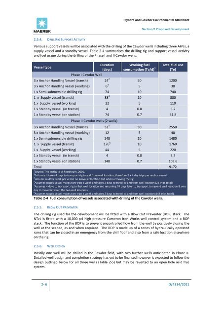
Various support vessels will be associated with the drilling of the <strong>Cawdor</strong> wells including three AHVs, a<br />
supply vessel <strong>and</strong> a st<strong>and</strong>by vessel. Table 2‐4 summarises the drilling rig <strong>and</strong> support vessel activity<br />
<strong>and</strong> fuel usage during the drilling of the Phase I <strong>and</strong> II <strong>Cawdor</strong> wells.<br />
Vessel type<br />
Duration<br />
(days)<br />
Phase I <strong>Cawdor</strong> Well<br />
Working fuel<br />
consumption (Te/d) 1<br />
Total fuel use<br />
(Te)<br />
3 x Anchor H<strong>and</strong>ling Vessel (transit) 24 2 50 1200<br />
3 x Anchor H<strong>and</strong>ling vessel (working) 6 3 5 30<br />
1 x Semi‐submersible drilling rig 74 10 740<br />
1 x Supply vessel (transit) 88 4 10 880<br />
1 x Supply vessel (working) 22 5 110<br />
1 x St<strong>and</strong>by vessel (in transit) 4 0.8 3.2<br />
1 x St<strong>and</strong>by vessel (on station) 74 0.7 51.8<br />
Phase II <strong>Cawdor</strong> wells (2 wells)<br />
3 x Anchor H<strong>and</strong>ling Vessel (transit) 51 5 50 2550<br />
3 x Anchor H<strong>and</strong>ling vessel (working) 12 5 40<br />
1 x Semi‐submersible drilling rig 148 10 1480<br />
1 x Supply vessel (transit) 176 6 10 1760<br />
1 x Supply vessel (working) 44 5 220<br />
1 x St<strong>and</strong>by vessel (in transit) 4 0.8 3.2<br />
1 x St<strong>and</strong>by vessel (on station) 148 0.7 103.6<br />
Total 9172<br />
1 Source; The Institute of Petroleum, 2000.<br />
2 Estimate it takes 4 days to transport rig to <strong>and</strong> from well location, therefore 2 X 4 day trips per anchor vessel.<br />
3 Assumes a days’ work per vessel on arrival at location <strong>and</strong> when removing the rig.<br />
4 Assumes supply vessel makes two trips a week <strong>and</strong> takes 2 days to travel to <strong>and</strong> from well location (22 trips total).<br />
5 Assumes 4 days to transport rig to first well location <strong>and</strong> returning 74 days later to transport to second well location & one<br />
day to move between the two well locations.<br />
6 Assumes supply vessel makes two trips a week <strong>and</strong> takes 2 days to travel to <strong>and</strong> from well locations (44 trips total).<br />
Table 2‐4 Fuel consumption of vessels associated with drilling of the <strong>Cawdor</strong> wells.<br />
2.5.5. BLOW OUT PREVENTER<br />
The drilling rig used for the development will be fitted with a Blow Out Preventer (BOP) stack. The<br />
NTvL is fitted with a 10,000 psi high pressure Cameron Iron Works well control system <strong>and</strong> a BOP<br />
stack. The function of the BOP is to prevent uncontrolled flow from the well by positively closing the<br />
well at the seabed, as <strong>and</strong> when required. The BOP is made up of a series of hydraulically operated<br />
rams that can be closed in an emergency from the drill floor <strong>and</strong> also from a safe location elsewhere<br />
on the rig.<br />
2.5.6. WELL DESIGN<br />
Initially one well will be drilled in the <strong>Cawdor</strong> field, with two further wells anticipated in Phase II.<br />
Detailed well design <strong>and</strong> completion strategy has yet to be finalised however is expected to follow the<br />
design outlined below for all three wells (Table 2‐5) but may be reverted to an open hole acid frac<br />
system.<br />
2‐ 6 D/4114/2011