Damage formation and annealing studies of low energy ion implants ...
Damage formation and annealing studies of low energy ion implants ...
Damage formation and annealing studies of low energy ion implants ...

You also want an ePaper? Increase the reach of your titles
YUMPU automatically turns print PDFs into web optimized ePapers that Google loves.
Yield (counts per 5 uC)<br />
350<br />
300<br />
250<br />
200<br />
150<br />
100<br />
50<br />
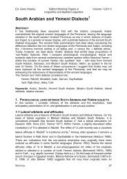
3keV As 2E15 <strong>ion</strong>/cm 2 - Si pr<strong>of</strong>iles: MEIS <strong>and</strong> XRD<br />
0<br />
-1<br />
0 1 2 3 4 5 6 7 8 9 10 11 12 13 14 15 16 17 18 19<br />
Depth (nm)<br />
This procedure demonstrates the excellent agreement <strong>of</strong> the SPER thickness<br />
measured by the two techniques. In fact both <strong>of</strong> the comparisons <strong>of</strong> MEIS with X-ray<br />
<strong>studies</strong> (sect<strong>ion</strong> 6.2.3.3 <strong>and</strong> 6.3.3.3) give corroborative results. It has again been shown<br />
how MEIS can be used as a starting point in the interpretat<strong>ion</strong> <strong>of</strong> the results <strong>of</strong> the X-ray<br />
<strong>studies</strong>, which could become increasingly useful for future defect <strong>studies</strong>.<br />
6.4 SOI regrowth<br />
6.4.1 Introduct<strong>ion</strong><br />
Annealing <strong>studies</strong> have been carried out to investigate the regrowth behaviour <strong>of</strong><br />
silicon on insulator (SOI). SOI wafers are produced from two bulk Si wafers. An oxide<br />
layer is grown on one <strong>of</strong> the wafers, which subsequently forms the buried oxide layer.<br />
Hydrogen <strong>ion</strong>s are implanted through the oxide into the underlying silicon <strong>and</strong> form a<br />
damage layer containing H bubbles at the end <strong>of</strong> the <strong>ion</strong>s range. The two wafers are then<br />
bonded together using Van der Waals forces. The implanted wafer is then cut across the<br />
damage plane leaving a thin layer <strong>of</strong> Si, which is then polished, on top <strong>of</strong> a buried oxide<br />
layer (23). The process is called Smart Cut (24, 25). The wafers used in these <strong>studies</strong><br />
have either a 60 nm, 88 nm or 100 nm Si layer on top <strong>of</strong> a buried SiO2 layer<br />
156<br />
virgin<br />
Epi as-implanted<br />
Epi 550C 200s<br />
Epi 600C 20s<br />
Epi 650C 10s<br />
Epi 700C 10s<br />
Figure 6.23 Comparison <strong>of</strong> MEIS depth pr<strong>of</strong>iles with the strain pr<strong>of</strong>ile from XRD after<br />
rescaling <strong>of</strong> the depth.<br />
6<br />
5<br />
4<br />
3<br />
2<br />
1<br />
0<br />
∆a/a (x 10 -3 )